scaling the ip ngn with unified mpls - proidea© 2010 cisco and/or its affiliates. all rights...
TRANSCRIPT
Cisco Confidential © 2010 Cisco and/or its affiliates. All rights reserved. 1
Scaling the IP NGN with Unified MPLS Istvan Kakonyi Vertical Solutions Architect
September 2012
© 2010 Cisco and/or its affiliates. All rights reserved. Cisco Confidential 2
• Introduction – Challenges ahead of Service Providers
• Evolution of MPLS Technology
• UMMT Architecture
Architecture Overview
UMMT Application in Mobile Networks
Resiliency
• Q and A

Cisco Confidential © 2010 Cisco and/or its affiliates. All rights reserved. 3

© 2010 Cisco and/or its affiliates. All rights reserved. Cisco Confidential 4
A 18x increase in mobile
data traffic over the next
5 years
Video to comprise >70%
of mobile data traffic by
2016
Machine-to-machine
Traffic to increase 22x
by 2016
Cisco Visual Networking Index: Global Mobile Data Traffic Forecast Update, 2011-2016

© 2010 Cisco and/or its affiliates. All rights reserved. Cisco Confidential 5
• High capacity requirements from edge to core:
100Mbps eNB, 1Gbps Access, 10Gbps Aggregation, 100Gbps Core
• Higher scale as LTE drives ubiquitous mobile broadband
Tens- to hundred-of-thousands of LTE eNBs and associated CSGs
• Support for multiple and mixed topologies
Fiber and microwave rings in access, fiber rings, and hub-and-spoke in aggregation and core networks
• Need for graceful LTE introduction to existing 2G/3G networks
Coexistence with GSM Abis, TDM backhaul, and ATM for UMTS IuB
• Need to support transport for all services from all locations
Residential and business, retail and wholesale, L2 and L3 services from cell site where this is the most cost effective location for the customer
• Optimized operations with consistent packet transport

Cisco Confidential © 2010 Cisco and/or its affiliates. All rights reserved. 6

© 2010 Cisco and/or its affiliates. All rights reserved. Cisco Confidential 7
Core Domain
MPLS/IP
IGP Area
Aggregation Node
Aggregation Node
Aggregation Node
Aggregation Domain MPLS/IP
IGP Area/Process
Aggregation Node
Aggregation Node
Aggregation Node
Aggregation Domain MPLS/IP
IGP Area/Process
RAN MPLS/IP
IGP Area/Process
RAN MPLS/IP
IGP Area/Process
Core
Core
Core
Core
Node Access Domain Aggregation Domain Network Wide
Cell Site Gateways 20 2,400 60,000
Pre-Aggregation Nodes 2 240 6,000
Aggregation Nodes NA 12 300
Core ABRs NA 2 50
Mobile transport Gateways NA NA 20
~ 67,000
IGP Routes!
~45
IGP
Routes
~45
IGP
Routes
~ 2,500
IGP Routes!
~ 2,500
IGP Routes!
LDP LSP LDP LSP LDP LSP
~254 IGP Routes
~ 6,020 BGP Routes
~45
IGP
Routes
~70 IGP Routes
~ 67,000 BGP Routes
~254 IGP Routes
~ 6,020 BGP Routes
~45
IGP
Routes
LDP LSP LDP LSP LDP LSP LDP LSP LDP LSP
iBGP Hierarchical LSP
Reduction in BGP routes towards Access
25 Aggregation Domains attached to the core!
120 Access Rings / Aggregation Domain !

© 2010 Cisco and/or its affiliates. All rights reserved. Cisco Confidential 8
Aggregati
on
Domain 1 Core
Aggregati
on
Domain 2 PE1
PE2
ABR-RR1 ABR-RR2
ABR-RR3 ABR-RR4
IGP area 1 IGP area 2 IGP area 3
BGP AS

© 2010 Cisco and/or its affiliates. All rights reserved. Cisco Confidential 9
ABR-RR1 ABR-RR2
PE1 PE2
Next-Hop-Self Next-Hop-Self
iBGP peers
iBGP peers
iBGP peers
IGP 1 IGP 2 IGP 3
ABRs are also Route Reflectors
PEs in the same segment peer with ABR-RRs
RRs are inserted in data path by setting next-hop-self
© 2010 Cisco and/or its affiliates. All rights reserved. Cisco Confidential 10
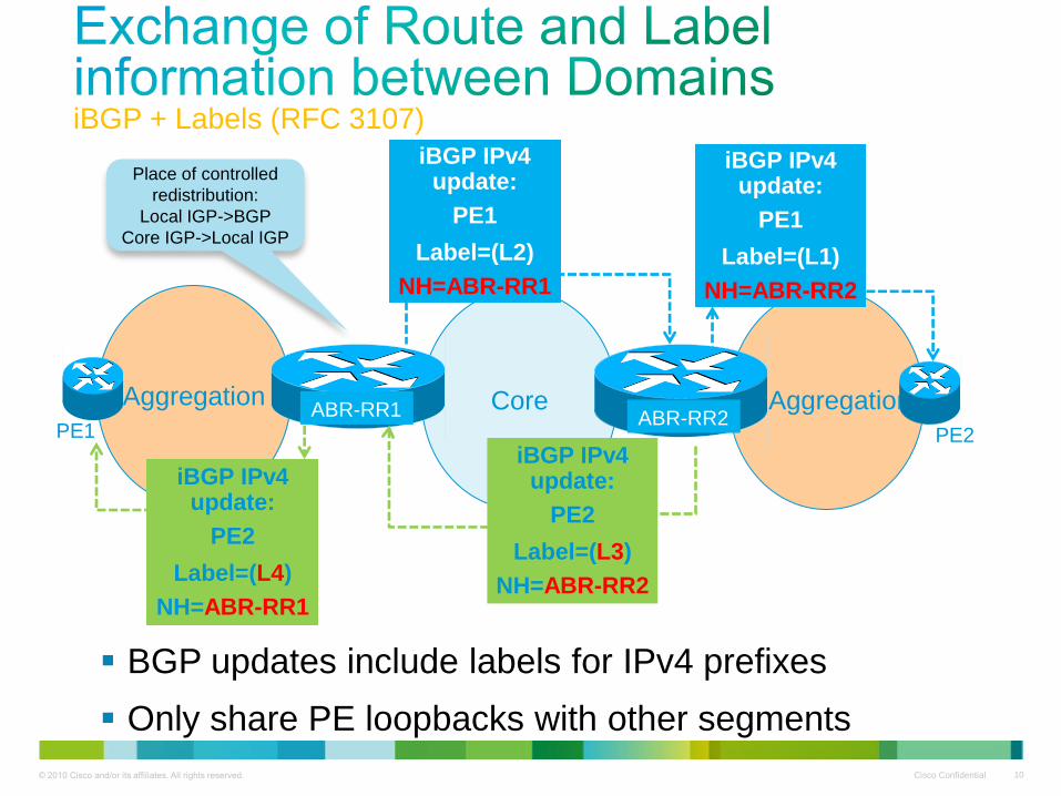
iBGP + Labels (RFC 3107)
Aggregation Aggregation Core PE1 PE2
iBGP IPv4 update:
PE1
Label=(L1)
NH=ABR-RR2
iBGP IPv4 update:
PE2
Label=(L4)
NH=ABR-RR1
ABR-RR1 ABR-RR2
iBGP IPv4 update:
PE2
Label=(L3)
NH=ABR-RR2
iBGP IPv4 update:
PE1
Label=(L2)
NH=ABR-RR1
BGP updates include labels for IPv4 prefixes
Only share PE loopbacks with other segments
Place of controlled
redistribution:
Local IGP->BGP
Core IGP->Local IGP

© 2010 Cisco and/or its affiliates. All rights reserved. Cisco Confidential 11
PE1 and PE2 exchange PW Virtual Circuit labels as usual
ABR-RR1 ABR-RR2
PE1 PE2
GE0/1
VCID:X
GE0/1
VCID:X
VCID:X
Label:Y
VCID:X
Label:Z
PW

© 2010 Cisco and/or its affiliates. All rights reserved. Cisco Confidential 12
Egress PE pops VC label
IGP and BGP labels are exchanged
Aggregation Aggregation Core
ABR-RR1 ABR-RR2 PE1 PE2
Z
21
L4
Z
22
L3 Z
23
BGP Label
IGP Label
PW VC Label
Payload

© 2010 Cisco and/or its affiliates. All rights reserved. Cisco Confidential 13
BGP Additional-path:
RR sends all paths for ABRs, and they perform path selection
RR performs path selection, sends path + additional path
Aggregation Aggregation Core
ABR-RR1 ABR-RR2
PE1 PE2
ABR-RR3 ABR-RR4
PE4
PE3
RR
(cluster-id 1) (cluster-id 2)
Supported
Today in
IOS/XR/XE

© 2010 Cisco and/or its affiliates. All rights reserved. Cisco Confidential 14
• Access, Aggregation and Core are in different IGP areas
• No or very limited IGP route redistribution from Core towards Aggregation areas
• Supports both single AS / multiple AS models
• RFC 3107 for label distribution (prefix+label through BGP):
PE loopbacks
Central Infrastructure: Edge Nodes, etc
• ABRs between IGP areas also act as BGP RRs
Next-hop self for inserting ABRs into the Data Path
Loop avoidance via Cluster-id
• BGP Additional-path + existing mechanisms for Fast convergence

Cisco Confidential © 2010 Cisco and/or its affiliates. All rights reserved. 15

© 2010 Cisco and/or its affiliates. All rights reserved. Cisco Confidential 16
MPLS MPLS MPLS
• In general transport platforms, a service has to be configured on every network element via operational points. The management system has to know the topology.
• Goal is to minimize the number of operational points
• With the introduction of MPLS within the aggregation, some static configuration is avoided.
• Only with the integration of all MPLS islands, the minimum number of operational points is possible.
MPLS
Access AGG AGG
LER LSR LER
AGG AGG Access
Operational Points

© 2010 Cisco and/or its affiliates. All rights reserved. Cisco Confidential 17
TDM/ATM
Pre-Aggregation Node
3800X, 3600X-24CX, ASR-903
DWDM, Fiber Rings, Mesh Topology DWDM, Fiber Rings, H&S, Hierarchical Topology Fiber or uWave Link, Ring
Core Network Mobile Access Network Aggregation Network
Core Node
CRS-3, ASR-9000
IP/MPLS Transport
BSC
ATM RNC
V4 or v6 MPLS VPN
SGW
TDM BTS/ATM NodeB
IP/MPLS Transport
Core Node
CRS-3, ASR-9000
Cell Site Gateway (CSG)
ASR-901
IP/MPLS Transport
SGW
MME
X2-C, X2-U
S1-U
S1-C
eNodeB
Mobile Transport Gateway (MTG) ASR-9000
MTG
MTG
MTG
MTG
Aggregation Node
ASR-9000
CSG
CSG

© 2010 Cisco and/or its affiliates. All rights reserved. Cisco Confidential 18

© 2010 Cisco and/or its affiliates. All rights reserved. Cisco Confidential 19
RAN IP/MPLS domain
Core Node
Core Node
Core Node
Core Node
LDP LSP LDP LSP LDP LSP LDP LSP LDP LSP
iBGP (eBGP across ASes) Hierarchical LSP
• The Mobile Core, Aggregation, Access Network enable Unified MPLS Transport
• The Core, Aggregation, Access are organized as independent IGP/LDP domains
• Core and Aggregation Networks may be in different Autonomous Systems, in which case the inter-
domain LSP is enabled by labeled eBGP in between ASes
• The network domains are interconnected with hierarchical LSPs based on RFC 3107, BGP
IPv4+labels. Intra domain connectivity is based on LDP LSPs
• The Access Network Nodes learn only the required labelled BGP FECs, with selective distribution of
the MPC and RAN neighbouring labelled BGP communities
RAN IP/MPLS domain
Core Network
IP/MPLS Domain
Pre-Aggregation Node
Aggregation Network
IP/MPLS
Domain
Aggregation Node
Pre-Aggregation Node
Aggregation Network
IP/MPLS
Domain
Core Node
Aggregation Node
Aggregation Node
Aggregation Node
Core Node
Core Node
Core Node
Mobile Transport GW
Mobile Transport GW
CSG
CSG
CSG CSG
CSG
CSG
Validated in
UMMT 3.0
© 2010 Cisco and/or its affiliates. All rights reserved. Cisco Confidential 20
Pre-Aggregation Node
ME-3800X, 3600-X, ASR-903
DWDM, Fiber Rings, Mesh Topology DWDM, Fiber Rings, H&S, Hierarchical Topology Fiber or uWave Link, Ring
Core Network Mobile Access Network Aggregation Network
Core ABR
CRS-3, ASR-9000
IP/MPLS Transport
IP/MPLS Transport
Core ABR
CRS-3, ASR-9000
Cell Site Gateway (CSG)
ASR-901
IP/MPLS Transport
Mobile Transport Gateway
(MTG) ASR-9000
Aggregation Node
ASR-9000
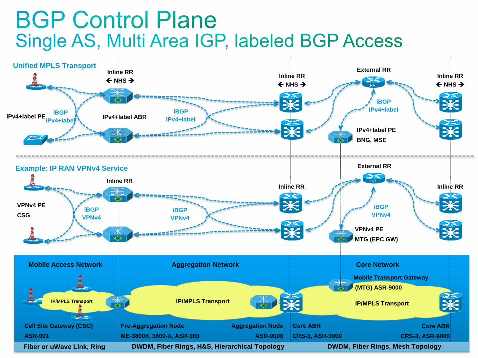
Example: IP RAN VPNv4 Service
Inline RR Inline RR
VPNv4 PE
CSG
Unified MPLS Transport
IPv4+label PE
BNG, MSE
Inline RR
NHS
External RR
IPv4+label ABR iBGP
IPv4+label
iBGP
VPNv4
VPNv4 PE
MTG (EPC GW)
iBGP
IPv4+label
iBGP
VPNv4 iBGP
VPNv4
Inline RR
NHS
Inline RR
RR
External RR
RR
iBGP
IPv4+label IPv4+label PE
Inline RR
NHS

© 2010 Cisco and/or its affiliates. All rights reserved. Cisco Confidential 21
LSPs between CSG and MTG Loopbacks
RAN IGP Domain Aggregation IGP Domain
PAN
Inline RR
CN-ABR
Inline RR
CSG MTG CN-ABR
Inline RR
Mobile Transport GW
Core IGP Domain
iBGP iBGP
iBGP IPv4+label iBGP IPv4+label
NHS 1- Control
NHS
iBGP IPv4+label iBGP IPv4+label
iBGP Hierarchical LSP
LDP LSP LDP LSP
LDP LSP
push
swap
swap pop
swap swap
iBGP Hierarchical LSP LDP LSP
LDP LSP LDP LSP
push
push
swap pop push
swap
swap pop
swap swap pop
1- Forwarding
2 - Forwarding
2- Control
NHS NHS
LDP Label
BGP Label
pop
Central RR
iBGP
iBGP IPv4+label
NHS
iBGP IPv4+label
Imp-Null
NHS
push
push
swap pop
NHS
NHS

© 2010 Cisco and/or its affiliates. All rights reserved. Cisco Confidential 22
Labeled BGP LSPs between Remote Access Nodes
Aggregation IGP Domain
PAN-ABR
Inline-RR
CN-ABR
Inline-RR
MTG
Core IGP Domain
iBGP iBGP
iBGP IPv4+label
Imp-Null
iBGP IPv4+label
Next-Hop-Self Next-Hop-Self
Central RR
CN-ABR
Inline-RR
PAN-ABR
Inline-RR
iBGP
Aggregation IGP Domain
Next-Hop-Self
iBGP IPv4+label
LDP LSP LDP LSP
pop push
swap
pop swap
swap swap pop
LDP Label
BGP Label
AN AN
Access IGP Domain Access IGP Domain
iBGP iBGP
push
push
swap push
swap
pop swap push
swap
pop swap
iBGP IPv4+label iBGP IPv4+label
Next-Hop-Self Next-Hop-Self
LDP LSP LDP LSP
LDP LSP iBGP Hierarchical LSP
Control
Forwarding

© 2010 Cisco and/or its affiliates. All rights reserved. Cisco Confidential 23
• Only the MPC community is distributed to RAN access
• The RAN Common Community is only distributed to MTGs

© 2010 Cisco and/or its affiliates. All rights reserved. Cisco Confidential 24
• Unified MPLS transport with a common MPLS VPN for LTE S1 from all CSGs and X2 per LTE region.
• Mobile Transport GWs import all RAN & MPC Route Targets, and export prefixes with MPC Route Target
• CSGs (and/or Pre-Aggregation Node) in a RAN region import the MPC and regional RAN Route Targets:
Enables S1 control and user plane with any MPC locations in the core
Enables X2 across CSGs in the RAN region
• MPLS VPN availability based on BGP PIC Edge and infrastructure LSP based LFA FRR
• Pre-Aggregation Nodes and Core POP Nodes form inline RR hierarchy for the MPLS VPN service
Core ABRs perform BGP community based Egress filtering to drop unwanted remote RAN VPNv4 prefixes
Pre-Aggregation Nodes implement RT Constrained Route Distribution towards CSR VPNv4 clients

© 2010 Cisco and/or its affiliates. All rights reserved. Cisco Confidential 25

© 2010 Cisco and/or its affiliates. All rights reserved. Cisco Confidential 26
BGP Inbound Route Filter 1) Accept MTG community 1001:1001
2) Accept remote loopbacks for configured wireline services
3) Drop
BGP Inbound Route Filter: 1) Accept MTG community 1001:1001
2) Accept remote loopbacks for configured wireline services
3) Drop
CSG
CSG
CN-RR RR
iBGP
IPv4 + label
Core Network
IS-IS L2
Access Network
OPSF 0 / IS-IS L2
Aggregation Network
IS-IS L1
Aggregation Network
IS-IS L1
Mobile Access Network
OPSF 0 / IS-IS L2
iBGP
IPv4 + label
iBGP
IPv4 + label
iBGP
IPv4 + label iBGP
IPv4 + label
CN-ABR
Inline RR
CN-ABR
Inline RR
BGP Egress filter towards CSGs: 1) Allow MTG community 1001:1001
2) Allow common wireline community 20:20
3) Drop
BGP Egress filter towards CSGs: 1) Allow MTG community 1001:1001
2) Allow common wireline community 20:20
3) Drop
CSG CSG
CSG
CSG
PAN
Inline RR
PAN
Inline RR
MTG
MTG
EoMPLS Pseudowire
Advertise loopback in iBGP with
Local RAN community 10:0201,
Common RAN community 10:10,
and Common Wireline Community
20:20
Advertise loopback in iBGP with
Local RAN community 10:0101,
Common RAN community 10:10,
and Common Wireline Community
20:20
• MTG and Common wireline communities distributed to RAN access
• Common RAN Community is only distributed to MTGs
• CSG accepts MTG & remote loopbacks for configured wireline services
© 2010 Cisco and/or its affiliates. All rights reserved. Cisco Confidential 27
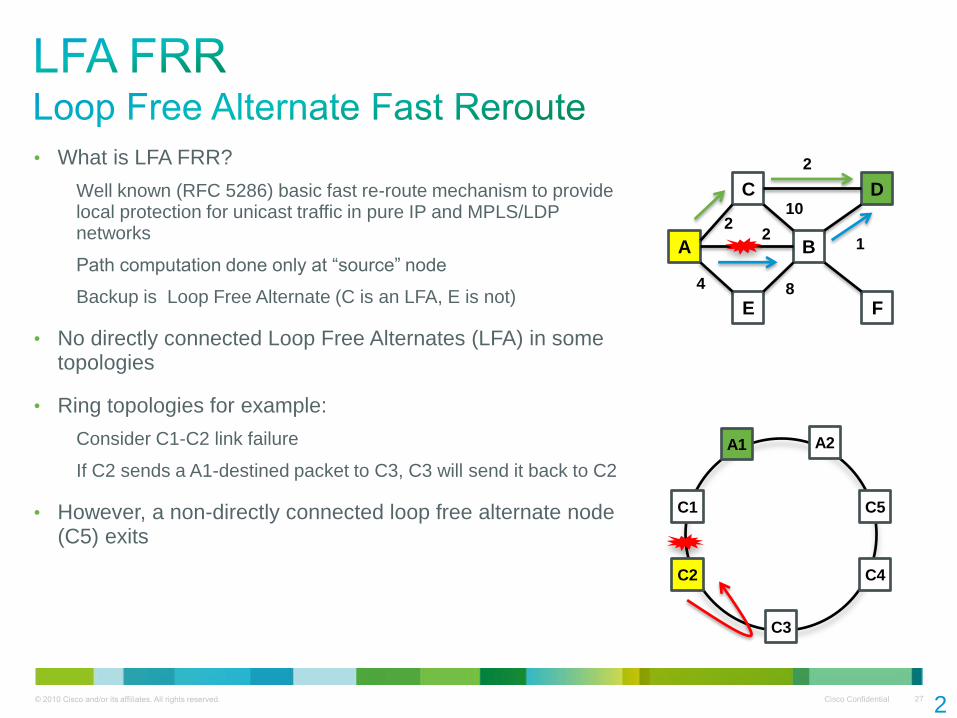
• What is LFA FRR?
Well known (RFC 5286) basic fast re-route mechanism to provide local protection for unicast traffic in pure IP and MPLS/LDP networks
Path computation done only at “source” node
Backup is Loop Free Alternate (C is an LFA, E is not)
• No directly connected Loop Free Alternates (LFA) in some topologies
• Ring topologies for example:
Consider C1-C2 link failure
If C2 sends a A1-destined packet to C3, C3 will send it back to C2
• However, a non-directly connected loop free alternate node (C5) exits
2
7
A
C
E
B
D
F
2 2
10
2
1
8 4
C1
C3
C5
A2 A1
C2 C4

© 2010 Cisco and/or its affiliates. All rights reserved. Cisco Confidential 28
http://tools.ietf.org/html/draft-shand-remote-lfa
• Remote LFA uses automated IGP/LDP behavior to extend basic LFA FRR to arbitrary topologies
• A node dynamically computes its remote loop free alternate node(s)
Done during SFP calculations using PQ algorithm (see draft)
• Automatically establishes a directed LDP session to it
The directed LDP session is used to exchange labels for the FEC in question
• On failure, the node uses label stacking to tunnel traffic to the Remote LFA node, which in turn forwards it to the destination
• Note: The whole label exchange and tunneling mechanism is dynamic and does not involve any manual provisioning
2
8
A1
C1
C2
C3
C4
A2
Backbone
Access Region
C5 Directed LDP
session
© 2010 Cisco and/or its affiliates. All rights reserved. Cisco Confidential 29
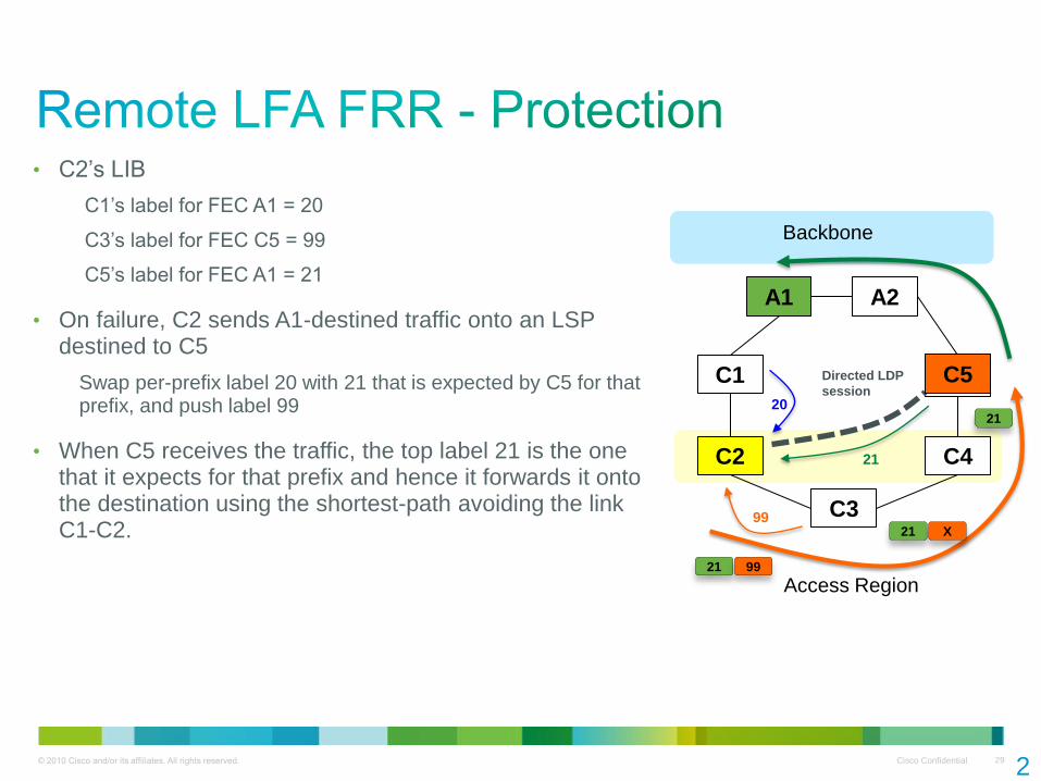
• C2’s LIB
C1’s label for FEC A1 = 20
C3’s label for FEC C5 = 99
C5’s label for FEC A1 = 21
• On failure, C2 sends A1-destined traffic onto an LSP destined to C5
Swap per-prefix label 20 with 21 that is expected by C5 for that prefix, and push label 99
• When C5 receives the traffic, the top label 21 is the one that it expects for that prefix and hence it forwards it onto the destination using the shortest-path avoiding the link C1-C2.
2
9
A1
C1
C2
C3
E1
C4
A2
Backbone
Access Region
C5 Directed LDP
session
21
20
99
21 99
21 X
21
© 2010 Cisco and/or its affiliates. All rights reserved. Cisco Confidential 30
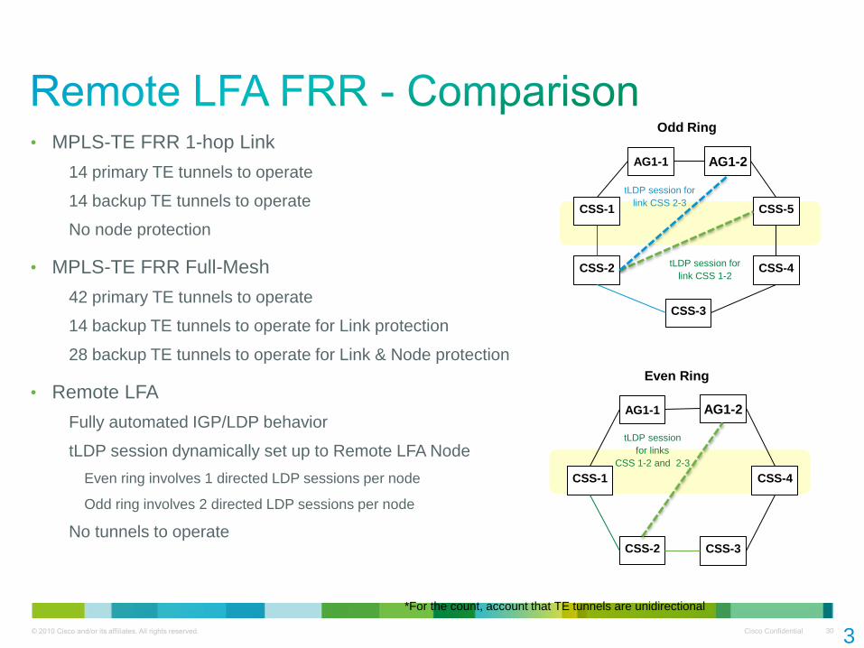
• MPLS-TE FRR 1-hop Link
14 primary TE tunnels to operate
14 backup TE tunnels to operate
No node protection
• MPLS-TE FRR Full-Mesh
42 primary TE tunnels to operate
14 backup TE tunnels to operate for Link protection
28 backup TE tunnels to operate for Link & Node protection
• Remote LFA
Fully automated IGP/LDP behavior
tLDP session dynamically set up to Remote LFA Node
Even ring involves 1 directed LDP sessions per node
Odd ring involves 2 directed LDP sessions per node
No tunnels to operate
3
0
AG1-1
CSS-1
CSS-2
CSS-3
CSS-4
AG1-2
CSS-5
*For the count, account that TE tunnels are unidirectional
Odd Ring
AG1-1
CSS-1
CSS-2 CSS-3
AG1-2
CSS-4
Even Ring
tLDP session for
link CSS 2-3
tLDP session for
link CSS 1-2
tLDP session
for links
CSS 1-2 and 2-3

© 2010 Cisco and/or its affiliates. All rights reserved. Cisco Confidential 32
• BGP Fast Reroute (BGP FRR)—enables BGP to use alternate paths within sub-seconds after a failure of the primary or active paths
• PIC or FRR dependent routing protocols (e.g. BGP) install backup paths
• Without backup paths
Convergence is driven from the routing protocols updating the RIB and FIB one prefix at a time - Convergence times directly proportional to the number of affected prefixes
• With backup paths
Paths in RIB/FIB available for immediate use
Predictable and constant convergence time independent of number of prefixes
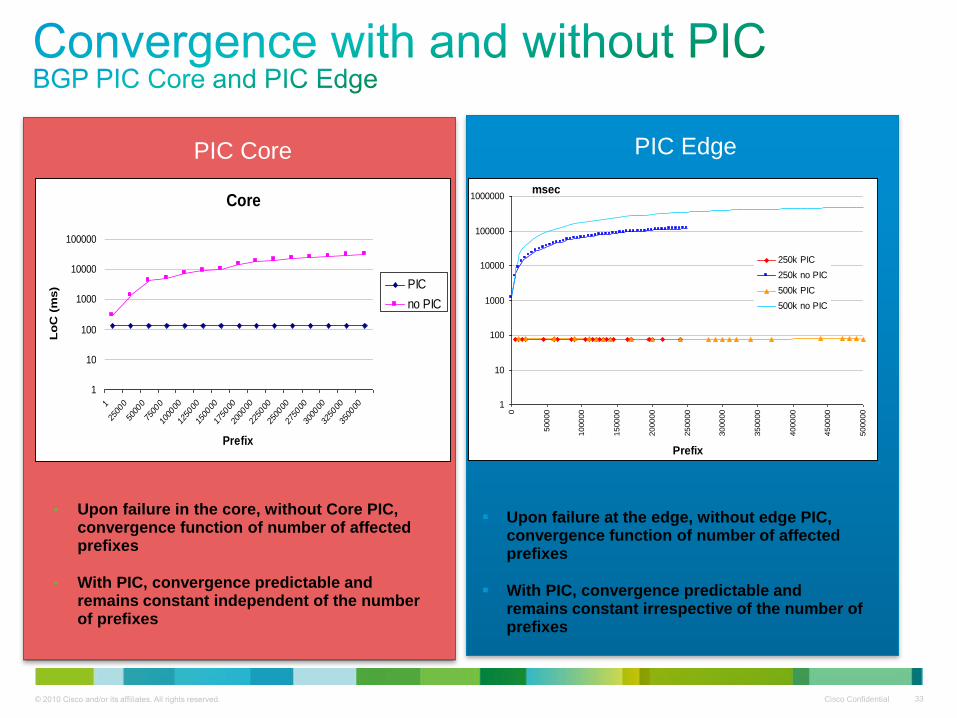
© 2010 Cisco and/or its affiliates. All rights reserved. Cisco Confidential 33
P
• Upon failure in the core, without Core PIC, convergence function of number of affected prefixes
• With PIC, convergence predictable and remains constant independent of the number of prefixes
Core
1
10
100
1000
10000
100000
1
2500
0
5000
0
7500
0
1000
00
1250
00
1500
00
1750
00
2000
00
2250
00
2500
00
2750
00
3000
00
3250
00
3500
00
Prefix
Lo
C (
ms) PIC
no PIC
1
10
100
1000
10000
100000
1000000
0
50000
100000
150000
200000
250000
300000
350000
400000
450000
500000
Prefix
msec
250k PIC
250k no PIC
500k PIC
500k no PIC
Upon failure at the edge, without edge PIC, convergence function of number of affected prefixes
With PIC, convergence predictable and remains constant irrespective of the number of prefixes
PIC Core PIC Edge

© 2010 Cisco and/or its affiliates. All rights reserved. Cisco Confidential 34
Aggregation Node
Aggregation Node
Aggregation Node
Aggregation Node
Aggregation Node
Aggregation Node
RAN IGP Process OSPF/ ISIS
Core
Core
Core
Core
LDP LSP LDP LSP LDP LSP LDP LSP LDP LSP
iBGP Hierarchical LSP
Aggregation Domain (OSPFx/ISIS1)
RAN Access
Core Domain
OSPF0/ISIS2
iBGP
Aggregation
BGP Community
iBGP
Aggregation
BGP Community
iBGP
iBGP
IPv4+Label
RR
Aggregation Domain (OSPFx/ISIS1)
RAN IGP Process OSPF/ ISIS
RAN Access
Core
Redistribute MPC
iBGP community
into RAN Access IGP
Redistribute
CSN Loopbacks
into 3107 iBGP
MPC PE
LFA L3 convergence < 50ms
BGP PIC Core L3 convergence < 100ms
BGP PIC Edge L3 convergence < 100ms

© 2010 Cisco and/or its affiliates. All rights reserved. Cisco Confidential 35
• Cisco Unified MPLS helps in building highly scalable MPLS networks where:
IGP domains are kept small
Number of operation points are minimized
Operation and troubleshooting kept simple
• Cisco Unified Transport for Mobile Networks provides:
An implementation of Unified MPLS
Tested, validated design with extensive support and documentation
Optimized for Mobile and converged fixed / mobile networks
Thank you.