scale-model test for disposal pit of high-level
TRANSCRIPT

Draft
Scale-model test for disposal pit of high-level radioactive waste and theoretical evaluation on self-sealing of
bentonite-based buffers
Journal: Canadian Geotechnical Journal
Manuscript ID cgj-2018-0805.R2
Manuscript Type: Note
Date Submitted by the Author: 06-Apr-2019
Complete List of Authors: Komine, Hideo ; Waseda University, Department of Civil and Environmental Engineering
Keyword: Bentonite, Self-sealing, Swelling, Radioactive waste disposal, Scale-model test
Is the invited manuscript for consideration in a Special
Issue? :Not applicable (regular submission)
https://mc06.manuscriptcentral.com/cgj-pubs
Canadian Geotechnical Journal

Draft
Date: 17 April, 2019
Scale-model test for disposal pit of high-level radioactive waste and theoretical evaluation on self-sealing of
bentonite-based buffers
Hideo KOMINE, Doctor of Engineering
Professor, Waseda University, Department of Civil and Environmental Engineering
3-4-1, Okubo, Shinjuku-ku, Tokyo, 169-8555, Japan
Telephone +81-3-5286-2940
Fax number +81-3-5286-3485
E-mail [email protected]
Page 1 of 19
https://mc06.manuscriptcentral.com/cgj-pubs
Canadian Geotechnical Journal

Draft
ABSTRACT
Bentonite is attracting greater attention in Japan and some other countries as a buffer for use in repositories of
high-level radioactive waste (HLW). Bentonite-based buffers for HLW disposal are expected, because of their
swelling deformation, to fill spaces between buffers and walls of disposal pits, or between buffers and waste
containers designated as overpack. Bentonite has self-sealing capability. This study conducts scale-model tests
simulating the relation between the buffer and interstitial space. It also investigates the validity of theoretical
equations for swelling presented by Komine and Ogata (2003; 2004) to evaluate buffer self-sealing capabilities by
comparing calculated and experimentally obtained results of scale-model tests. Results of the experimental work
described herein and calculations highlighted bentonite’s self-sealing capability and demonstrated the high
applicability of equations of Komine and Ogata (2003; 2004) to quantify filling of interstitial spaces by
bentonite-based buffer swelling.
Keywords: Bentonite, Self-sealing, Swelling, Radioactive waste disposal, Scale-model test
Page 2 of 19
https://mc06.manuscriptcentral.com/cgj-pubs
Canadian Geotechnical Journal

Draft
INTRODUCTION
Bentonite is attracting greater attention for use as a buffer material in repositories of high-level radioactive
waste (HLW) in Japan and other countries. When used for HLW disposal applications, bentonite-based buffers,
because of their swelling deformation, are expected to fill interstitial spaces between buffers and walls of disposal
pits, and between buffers and waste containers. Bentonite-based buffers have a so-called self-sealing capability.
Figure 1 portrays schematic drawings of an HLW disposal facility and an image illustrating the self-sealing
capability of bentonite-based buffers.
To design and develop bentonite-based buffer specifications that can ensure self-sealing capability, the author
earlier proposed theoretical equations for swelling characteristics of bentonite-based buffer (Komine and Ogata
2003,2004). Moreover, the author validated those theoretical equations by comparing the calculated results with
many experimentally obtained results of swelling pressure and swelling deformation characteristics of various
bentonites and sand-bentonite mixtures.
To clarify the extended applicability of the theoretical equations proposed by the author, this study investigates
bentonite-based buffers’ self-sealing capability using scale-model tests of a disposal pit and the component
materials. This study also assessed the validity of the theoretical equations proposed by Komine and Ogata
(2003,2004) by comparing the results of calculations and experiments.
Many earlier studies exploring swelling of bentonite-based buffers have used experimentation to assess the
fundamental swelling properties of bentonite (Agus and Schanz 2008; Alonso et al. 1999; Cui et al. 2002; Delage et
al. 1998; Komine and Ogata 1994,1996,2003,2004; Villar and Lloret 2008). Recently, some studies of bentonite
swelling in different environmental conditions such as seawater and high temperatures have also been reported from
elementary experiments (Karnland et al. 2007; Komine et al. 2009; Villar et al. 2010). Some studies have used
numerical analyses and field measurements (e.g. Garitte et al. 2017). By contrast, few reports describe studies using
scale-model testing of bentonite-based buffer. A few studies have assessed the self-sealing capability of
bentonite-based buffer considering the relation between buffer swelling and interstitial space in the disposal pit and
component materials. This study specifically examines the view above and investigates the self-sealing capability of
bentonite-based buffer quantitatively.
Page 3 of 19
https://mc06.manuscriptcentral.com/cgj-pubs
Canadian Geotechnical Journal

Draft
SCALE-MODEL TESTING OF DISPOSAL PIT AND COMPONENT MATERIALS
This section presents a description of the scale-model test to simulate a disposal pit for HLW disposal
presented in Fig. 1 and component materials. The scale-model test is axially symmetric, illustrating the relation
between a buffer and space in a disposal pit.
Materials
This study used the sodium-type commercial bentonite, designated as Kunigel-V1 (2.79 Mg/m3 particle
density) produced before 1999 at the Tsukinuno Mine in Japan. The montmorillonite contents were calculated using
methylene blue absorption values of each bentonite and montmorillonite (White and Michael 1979). The methylene
blue absorption values of the old Kunigel-V1 are 67 meq/100 g. That of montmorillonite is 140 meq/100 g.
Therefore, the montmorillonite content of the old Kunigel-V1 used for this study is nearly 48%.
The bentonite used for the present study was kept in a room at a constant temperature (22 1 °C) and almost
constant humidity (70–80%). The water contents of this material were 7.2–14.0%. This study also used Mikawa
silicate sand No. 6, with particles having 2.66 Mg/m3 density and 0.053–0.590 mm diameter.
Buffer specimen specifications and procedures
This study produced compacted bentonites and compacted mixtures of sand and bentonite of five kinds as
buffer specimens. The Central Research Institute of Electric Power Industry (CRIEPI) and The Federation of
Electric Power Companies of Japan (FEPC) proposed an example of the design of disposal pit and component
materials in Fig. 2 (Ogata et al. 1999). According to the above proposal by the CRIEPI and the FEPC, the external
form of bentonite-based buffer is toroidal. Also, the buffer outer diameter is 1620 mm; the inner diameter is 820 mm,
with horizontal thickness of 400 mm. The toroidal specimen scale, as portrayed in Fig. 3(a), is approximately
one-fifth of the specification above. Therefore, the specimen outer diameter is 332 mm; the inner diameter is 172
mm, with 80 mm horizontal thickness. The specimen height is 50 mm. The toroidal form is an effective candidate
because constructing the buffer area is easy, as shown in Figs. 1 and 2.
This study used specimens of four kinds as explained by Ogata et al. (1999): those with dry densities of 1.62
Mg/m3 and 1.77 Mg/m3 for bentonite content of 80% and those with 1.61 Mg/m3 and 1.84 Mg/m3 for bentonite
content of 100%. The study also used buffer specimens with dry density of 1.81 Mg/m3 and bentonite content 70%,
referring to the Japan Nuclear Cycle Development Institute (2000a,b).
Page 4 of 19
https://mc06.manuscriptcentral.com/cgj-pubs
Canadian Geotechnical Journal

Draft
For toroidal specimen production, production jigs such as a mold and piston were made as presented in Fig.
3(b). This study used the compression apparatus of which the maximum capacity of the compression load is 5000
kN and the compression stress for producing specimens is 1.09–31.59 MPa. The compression duration is 15 min for
all specimens.
Experimental apparatus and test procedure
This study used the experimental apparatus portrayed in Fig. 4, which simulated a waste container, a
bentonite-based buffer, surrounding rock, and the interstitial space among components at the horizontal/radial
direction. Those specifications above include the following: 400 mm buffer thickness, 40 mm space between the
buffer and pit wall, and 10 mm space between the buffer and container. To measure the buffer pressure after filling
up space, three pressure gauges were attached to the acrylic cell as shown in the right drawing of Fig. 4. The
maximum pressure gauge capacity is 2000 kPa. The minimum scale is 0.5 kPa. The pressure gauge diameter is 5
mm. For that reason, they are almost non-protuberant on the acrylic cell wall, which has 332 mm inner diameter. As
portrayed in Fig. 4, a toroidal specimen of bentonite-based buffer was set on the center of the apparatus. Distilled
water was supplied to a specimen from the full-part bottom for approximately two months (59–63 days) to elucidate
the relation between the buffer specimen pressure and the elapsed time. The above measuring period was
determined by reason that the buffer specimen pressure was convergently almost constant value at that period as
after-mentioned in Fig. 5 and the related paragraph.
In these experiments, vertical pressure gauges were not included because they might be obstructive to
supplying distilled water as described above. It is also well-known that swelling behavior of bentonite is affected
water chemistry, therefore this study was using distilled water.
Experimental results
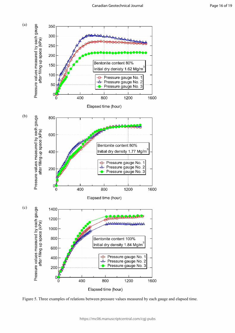
Figure 5 presents the relation between buffer’s lateral pressures after filling the space and the elapsed time.
This figure exemplifies three kinds of experimentally obtained results of the cases of bentonite content 80%, initial
dry densities are 1.62 Mg/m3 and 1.77 Mg/m3, and bentonite content 100%, initial dry density is 1.84 Mg/m3. Those
results indicate that buffer’s lateral pressures after filling the space are increasing as bentonite content and initial dry
density are increasing. Result presented in Fig. 5(a) shows that the variation of lateral pressures measured by the
three pressure gauges attached to the acrylic cell are within the range of around 20% for bentonite content 80% and
initial dry density 1.62 Mg/m3. From the results shown in Figs. 5(b) and 5(c), the variation of lateral pressures
Page 5 of 19
https://mc06.manuscriptcentral.com/cgj-pubs
Canadian Geotechnical Journal
Draft
measured for bentonite content 80%, initial dry density 1.77 Mg/m3 and bentonite content 100%, initial dry density
is 1.84 Mg/m3 are in the range of around 10%. The tendency on increasing the lateral pressures are found to be
almost same as shown in all of the drawings in Fig. 5. Figure 6 portrays the relation between the average pressure of
buffer after filling the space and the elapsed time in all experimental cases. Figure 7 presents observations of space
filling by swelling of the bentonite-based buffer. Results demonstrate that the bentonite-based buffer has practical
self-sealing capability to fill the space between the buffer and the disposal pit wall. Figure 7 also indicates that
seepage water distributed roughly around whole parts of specimen from the viewpoint of color alternation.
TRIAL EVALUATION OF SELF-SEALING CAPABILITY OF BENTONITE-BASED BUFFER BY
THEORETICAL EQUATIONS IN KOMINE AND OGATA (2003,2004)
This section describes the trial evaluation of self-sealing capability of bentonite-based buffer by the theoretical
equations for swelling characteristics of bentonite in Komine and Ogata (2003,2004). Figure 8 presents the
schematic drawing of author’s theoretical equations and the evaluating flow chart on self-sealing of bentonite-based
buffer by using them.
Firstly, this study investigated the applicability of author’s theoretical equations to evaluate the buffer
self-sealing capability by comparing the calculations and experimentally obtained results described earlier. Table 2
presents parameters determined by the fundamental properties of bentonite and sand. Figure 9 shows a comparison
of the calculated results with experimentally obtained results. In the calculation, the ion concentration of pore water,
n0 is assumed as 30 and 40 mol/m3 by referring previously measured values in Komine and Ogata (2003,2004). It is
well-known that swelling behavior of bentonite is influenced by pore water chemistry, so it is considered that the
difference between the calculated results and measured values is partially caused by the accuracy for assuming
values of n0. Moreover, it is also considered the possibility of hydrating non-homogeneously bentonite block during
those experimental periods. However, the prediction results can indicate approximately the experimentally
measured values. From the above discussion, the theoretical equations proposed in Komine and Ogata (2003; 2004)
are regarded to use for designing the buffer specifications such as the bentonite content, the compaction density, and
the dimensions from the viewpoint of “self-sealing.”
For trial evaluating the buffer’s self-sealing capability, the conditions of the disposal pit shown in the lower
right drawings of Fig. 1 are simulated using analytical models and author’s theoretical equations. Presumably, the
swelling deformation of bentonite-based buffers is equal to the interstitial spaces filled up by buffer swelling
Page 6 of 19
https://mc06.manuscriptcentral.com/cgj-pubs
Canadian Geotechnical Journal

Draft
deformation. Consequently, the relation of the maximum swelling strain, max (%) of buffer is calculable by the
initial buffer volume and the initial volume of interstitial spaces.
For evaluating the buffer self-sealing capability, the following are assumed.
Assumption 1: Buffer pressure is homogeneous after the interstitial spaces are filled.
Assumption 2: The one-dimensional model consists of a waste container, buffer materials, the disposal pit wall,
and interstitial spaces.
Bentonite-based buffers are presumably non-homogeneous when they are manufactured because of the thin
layers of montmorillonite minerals that are arranged in a certain direction during compaction. The direction of
montmorillonite minerals, however, will be disturbed during the unrestricted swelling process by which spaces are
filled. The buffer will be almost hydrated in almost homogeneous after so long-time later such as 10,000 years.
Therefore, the author adopted assumption 1 presented above. However, the assurance of the above phenomena
should be continued to investigate. The analytical model is established as a one-dimensional model.
In calculating and evaluating the buffer’s self-sealing capability, the key point is to consider and calculate the
maximum swelling strain, max (%) of buffer by derivation from the relation between the width of interstitial space
and the bentonite-based buffer thickness by assuming a one-dimensional model of the buffer and space.
The required buffer capacity can be ascertained provided that the buffer pressure after filling up interstitial
space to create an effective self-sealing capability is configurable. For instance, it is presumed that self-sealing
capability is effective when the buffer pressure after filling up space is greater than 1000 kPa. Some earlier studies
conducted in Canada (Atomic Energy of Canada Limited 1994; Dixon and Gray 1996; Dixon et al. 1987) have
demonstrated that the required buffer pressure having effective low permeability is greater than 1000 kPa. Therefore,
the conditions explained above related to the buffer pressure for effective self-sealing are assumed. Figure 10
presents an example of self-sealing of bentonite-based buffer according to the evaluating flow on self-sealing of
bentonite-based buffer presented in Fig. 8. It can calculate and evaluate the required buffer-thickness from the
viewpoint of effective self-sealing capability according as material specifications such as kinds of bentonite, dry
density and bentonite content with some assumptions such as 1000 kPa of the buffer pressure for effective
self-sealing capability. This study adopted provisionally 1000 kPa of buffer pressure after filling up space for
effective self-sealing from the previous researches. It is necessary to clarify highly reliable buffer pressure for
effective self-sealing capability by future researches.
Page 7 of 19
https://mc06.manuscriptcentral.com/cgj-pubs
Canadian Geotechnical Journal

Draft
CONCLUSIONS
For this study, we conducted scale-model tests simulating the relations of buffer and the interstitial space
between buffer materials and a disposal pit wall, and between buffer materials and a waste container. Then we
evaluated the buffer self-sealing capability quantitatively. The experimentally obtained results of scale model tests
indicate that the bentonite-based buffer has practical self-sealing capability to fill interstitial spaces. Moreover, this
study introduced the trial evaluation of self-sealing capability of bentonite-based buffer by the author’s theoretical
equations when it is asuumed that buffer pressure is homogeneous after the interstitial spaces are filled and the
one-dimensional model consists of a waste container, buffer materials, the disposal pit wall, and interstitial spaces.
ACKNOWLEDGMENTS
This study, supported by research funds from the Japanese Ministry of Education, Culture, Sports, Science and
Technology, was performed as a part of activities of Research Institute of Sustainable Future Society, Waseda
Research Institute for Science and Engineering, Waseda University. The scale model test was strongly supported by
Dr. Ueda in the Radioactive Waste Management Funding and Research Center (Formerly Tokyo Electric Power
Co.), and by Mr. Takao and Mr. Osada of JGS Corporation. The author thanks all members listed above and also the
staff and students of the geotechnical laboratory of Waseda University for their kind assistance and discussion.
REFERENCES
Agus, S. S., and Schanz, T. 2008. A method for predicting swelling pressure of compacted bentonites. Acta
Geotechnica, 3: 125–137.
Alonso, E. E., Vaunat, J., and Gens, A. 1999. Modelling the mechanical behaviour of expansive clays. Engineering
Geology, 54: 173–183.
Atomic Energy of Canada Limited 1994. The Disposal of Canada's Nuclear Fuel Waste: Engineered Barriers
Al-ternatives, AECL-10719 COG-93-8, Whiteshell Laboratories Pinawa, Manitoba R0E 1L0.
Cui, Y. J., Yahia-Aissa, M., and Delage, P. 2002. A model for the volume change behavior of heavily compacted
swelling clays. Engineering Geology, 64: 233–250.
Page 8 of 19
https://mc06.manuscriptcentral.com/cgj-pubs
Canadian Geotechnical Journal

Draft
Delage, P., Howat, M. D., and Cui, Y. J. 1998. The relationship between suction and swelling properties in a heavily
compacted unsaturated clay. Engineering Geology, 50(1-2): 31–48.
Dixon, D. A., and Gray, M. N. 1996. Swelling and hydraulic properties of bentonites from Japan, Canada and the
USA. In Proceedings of the Second International Congress on Environmental Geotechnics (IS-Osaka), Vol. 1,
Osaka, 5-8 November 1996. Japanese Geotechnical Society, Tokyo, pp. 43–48.
Dixon, D. A., Gray, M. N., Cheung, S. C. H., and Davidson, B. C. 1987. The hydraulic conductivity of dense clay
soils in geotechnique in resource development. In Proceedings of the 40th Canadian Geotechnical
Conference, Regina, Saskatchewan, 19-21 October 1987, The Canadian Geotechnical Society, Richmond, pp.
389–396.
Garitte, B., Shao, H., Wang, X. R., Nguyen, T. S., Li, Z., Rutqvist, J., Birkholzer, J., Wang, W. Q., Kolditz, O., Pan,
P. Z., Feng, X. T., Lee, C., Graupner, B. J., Maekawa, K., Manepally, C., Dasgupta, B., Stothoff, S., Ofoegbu,
G., Fedors, R., and Barnichon, J. D. 2017. Evaluation of the predictive capability of coupled
thermo-hydromechanical models for a heated bentonite/clay system (HE-E) in the Mont Terri Rock
Laboratory. Environment Earth Sciences, 76:64: 1-18. doi: 10.1007/s12665-016-6367-x.
Japan Nuclear Cycle Development Institute (Japan Atomic Energy Agency at present) 2000a. H12: Project to
establish the scientific and technical basis for HLW disposal in Japan, Project Overview Report, JNC
TN1410 2000-001.
Japan Nuclear Cycle Development Institute (Japan Atomic Energy Agency at present) 2000b. H12: Project to
establish the scientific and technical basis for HLW disposal in Japan, Supporting report 2, Repository
Design and Engineering Technology, JNC TN1410 2000-003.
Karnland, O., Olsson, S., Nilsson, U., and Sellin, P. 2007. Experimentally determined swelling pressures and
geochemical interactions of compacted Wyoming bentonite with highly alkaline solutions. Physics and
Chemistry of the Earth, 32: 275–286.
Komine, H., and Ogata, N. 1994. Experimental study of swelling characteristics of compacted bentonite. Canadian
Geotechnical Journal, 31(4): 478–490. doi: 10.1139/t94-057.
Komine, H., and Ogata, N. 1996. Prediction for swelling characteristics of compacted bentonite. Canadian
Geotechnical Journal, 33(1): 11–22. doi: 10.1139/t96-021.
Komine, H., and Ogata, N. 1999. Experimental study of swelling characteristics of sand-bentonite mixture for
nuclear waste disposal. Soils and Foundations, 39(2): 83–97. doi: 10.3208/sandf.39.2_83.
Komine, H., and Ogata, N. 2003. New equations for swelling characteristics of bentonite-based buffer materials.
Page 9 of 19
https://mc06.manuscriptcentral.com/cgj-pubs
Canadian Geotechnical Journal

Draft
Canadian Geotechnical Journal, 40(2): 460–475. doi: 10.1139/t02-115.
Komine, H., and Ogata, N. 2004. Predicting swelling characteristics of bentonites. Journal of Geotechnical and
Geoenvironmental Engineering, American Society of Civil Engineers (ASCE), 130(8): 818–829. doi:
10.1061/(ASCE)1090-0241(2004)130:8(818).
Komine, H., Yasuhara, K., and Murakami, S. 2009. Swelling characteristics of bentonites in artificial seawater.
Canadian Geotechnical Journal, 46: 177–189. doi: 10.1139/t08-120.
Ogata, N., Kosaki, A, Ueda, H., Asano, H., and Takao, H. 1999. Execution techniques for high level radioactive
waste disposal: IV Design and manufacturing procedure of engineered barriers. Journal of Nuclear Fuel
Cycle and Environment, 5(2): 103–121 (in Japanese with English abstract).
Villar, M. V., Gómez-Espina1, R., and Lloret, A. 2010. Experimental investigation into temperature effect on
hydro-mechanical behaviours of bentonite. Journal of Rock Mechanics and Geotechnical Engineering, 2(1):
71–78.
Villar, M. V., and Lloret, A. 2008. Influence of dry density and water content on the swelling of a compacted
bentonite. Applied Clay Science, 39(1-2): 38–49.
White, D., and Michael, G. P. 1979. A proposed method for the determination of small amounts of smectites in clay
mineral mixtures. Proceedings of British Ceramics Society, 28: 137–145.
Page 10 of 19
https://mc06.manuscriptcentral.com/cgj-pubs
Canadian Geotechnical Journal

Draft
Figure Captions
Figure 1. Schematic drawings of HLW disposal facility and self-sealing ability of bentonite-based buffers with
reference to the concepts of Atomic Energy of Canada Limited (1994) and Japan Nuclear Cycle
Development Institute (2000a,2000b).
Figure 2. Vertical disposal pit dimensions proposed in CRIEPI and FEPC.
Figure 3. Size and outline of toroidal buffer specimen, and specimen production jigs.
Figure 4. Scale-model test apparatus simulated disposal pit of HLW and component materials: a simulated waste
container, a bentonite-based buffer, surrounding rock, and the space between components.
Figure 5. Three examples of relations between pressure values measured by each gauge and elapsed time.
Figure 6. Relation between average pressure of buffer after filling up space and elapsed time.
Figure 7. Filling up space by swelling of bentonite-based buffer.
Figure 8. Evaluating flow on self-sealing of bentonite-based buffer by the theoretical equations for swelling of
bentonite in Komine and Ogata (2003,2004).
Figure 9. Comparison of calculated and experimentally obtained results.
Figure 10. Trial evaluating results of self-sealing capability of bentonite-based buffer using theoretical equations
according to Komine and Ogata (2003,2004).
Page 11 of 19
https://mc06.manuscriptcentral.com/cgj-pubs
Canadian Geotechnical Journal

Draft
Table 1. Fundamental properties of bentonite (the Kunigel-V1 produced before 1999) in this study
Type Sodium type
Particle density 2.79 Mg/m3
Liquid limit 473.9%
Plastic limit 26.6%
Plastic index 447.3
Activity 6.93
Plastic ratio 16.81
Clay content 64.5%
Montmorillonite content 48%
Cation exchange capacity 0.732 meq/g
Exchangeable sodium ion capacity 0.405 meq/g
Exchangeable calcium ion capacity 0.287 meq/g
Exchangeable potassium capacity 0.009 meq/g
Exchangeable magnesium capacity 0.030 meq/g
Table 2. Parameters ascertained from fundamental properties of bentonite and sand
m nm Sm Snm Cm
2.77 Mg/m3 2.81 Mg/m3 810 m2/g 0 m2/g 48%
CEC EXCNa+ EXCCa
+ EXCK+ EXCMg
+
0.732 meq/g 0.405 meq/g 0.287 meq/g 0.009 meq/g 0.030 meq/g
(Rion)Na (Rion)Ca (Rion)K (Rion)Mg Na
0.098 nm 0.1115 nm 0.133 nm 0.0835 nm 1
Ca K Mg t sand
2 1 2 9.60×10⁻¹⁰ m 2.66 Mg/m3
Those parameters are determined based on values quoted from earlier papers and the measured values of Kunigel-V1 bentonite and Mikawa silicate sand No. 6.
Page 12 of 19
https://mc06.manuscriptcentral.com/cgj-pubs
Canadian Geotechnical Journal

Draft
Figure 1. Schematic drawings of HLW disposal facility and self-sealing ability of bentonite-based buffers with
reference to the concepts of Atomic Energy of Canada Limited (1994) and Japan Nuclear Cycle
Development Institute (2000a,2000b).
Figure 2. Vertical disposal pit dimensions proposed in CRIEPI and FEPC.
Page 13 of 19
https://mc06.manuscriptcentral.com/cgj-pubs
Canadian Geotechnical Journal

Draft
(a)
(b)
Figure 3. Size and outline of toroidal buffer specimen, and specimen production jigs.
Page 14 of 19
https://mc06.manuscriptcentral.com/cgj-pubs
Canadian Geotechnical Journal

Draft
Figure 4. Scale-model test apparatus simulated disposal pit of HLW and component materials: a simulated waste
container, a bentonite-based buffer, surrounding rock, and the space between components.
Page 15 of 19
https://mc06.manuscriptcentral.com/cgj-pubs
Canadian Geotechnical Journal
Draft
(a)
(b)
(c)
Figure 5. Three examples of relations between pressure values measured by each gauge and elapsed time.
Page 16 of 19
https://mc06.manuscriptcentral.com/cgj-pubs
Canadian Geotechnical Journal

DraftFigure 6. Relation between average pressure of buffer after filling up space and elapsed time.
Figure 7. Filling up space by swelling of bentonite-based buffer.
Page 17 of 19
https://mc06.manuscriptcentral.com/cgj-pubs
Canadian Geotechnical Journal

Draft
𝑝 =1
𝐶𝐸𝐶 ∑𝑖 = 𝑁𝑎 + , 𝐶𝑎2 +
𝐾 + ,𝑀𝑔2 +
[𝐸𝑋𝐶𝑖{(𝑓𝑟)𝑖 ― (𝑓𝑎)𝑖}] (1)
(𝑓𝑟)𝑖 = 2𝑛𝑘𝑇(cosh 𝑢𝑖 ― 1) × 10 ―3 (1-a)
𝑢𝑖 = 8 tanh ―1 [exp ( ― 𝑖𝑑𝑖)tanh (𝑧𝑖
4)] (1-b)
𝑖 =2𝑛2
𝑖 𝑒′2
𝜀𝑘𝑇
(1-c)
𝑧𝑖 = 2sinh ―1 (96.5 ×𝐸𝑋𝐶𝑖
𝑆1
8𝜀𝑛𝑘𝑇) (1-d)
(𝑓𝑎)𝑖 =𝐴ℎ
24𝜋[ 1
𝑑3𝑖
+1
(𝑑𝑖 + 𝑡)3 ―2
(𝑑𝑖 +𝑡2)3] (1-e)
𝜀 ∗𝑠𝑣 = {𝑒0 +
𝜀𝑠𝑚𝑎𝑥
100(𝑒0 + 1)}{1 + (100
𝐶𝑚― 1) 𝜌𝑚
𝜌𝑛𝑚+ (100
𝛼 ― 1)100𝐶𝑚
𝜌𝑚
𝜌𝑠𝑎𝑛𝑑} (1-f)
𝑒0 =𝜌𝑠𝑜𝑙𝑖𝑑
𝜌𝑑0― 1
(1-g)
𝜌𝑠𝑜𝑙𝑖𝑑 =
100𝐶𝑚
100𝛼 𝜌𝑚
{1 + (100𝐶𝑚
― 1) 𝜌𝑚
𝜌𝑛𝑚+ (100
𝛼 ― 1)100𝐶𝑚
𝜌𝑚
𝜌𝑠𝑎𝑛𝑑}(1-h)
𝑑𝑖 =𝜀 ∗
𝑠𝑣
100{𝑡 + (𝑅𝑖𝑜𝑛)𝑖} + (𝑅𝑖𝑜𝑛)𝑖
(1-i)
𝑛 =𝑛0 (mol m3) × 𝑁𝐴
1 +𝜀 ∗
𝑠𝑣
100
(1-j)The details of the variables of physical, chemical and physical chemistry in the
equations have been explained in Komine and Ogata (2003,2004) so refer them.
𝑆 =𝐶𝑚
100𝑆𝑚 + (1 ―𝐶𝑚
100)𝑆𝑛𝑚(1-k)
Figure 8. Evaluating flow on self-sealing of bentonite-based buffer by the theoretical equations for swelling of bentonite in Komine and Ogata (2003; 2004).
Page 18 of 19
https://mc06.manuscriptcentral.com/cgj-pubs
Canadian Geotechnical Journal

DraftNotation: BC is bentonite content, IDD is Initial dry density and n0 is ion concentration of pore water in theoretical
calculation.
Figure 9. Comparison of calculated and experimentally obtained results.
Figure 10. Trial evaluating results of self-sealing capability of bentonite-based buffer using theoretical equations
according to Komine and Ogata (2003,2004).
Page 19 of 19
https://mc06.manuscriptcentral.com/cgj-pubs
Canadian Geotechnical Journal