scalable and cost-effective framework for continuous media ... · framework for continuous...
TRANSCRIPT

Scalable and Cost-Effective
Framework for Continuous
Media-On-Demand
Dang Nam Chi Nguyen
A Thesis presented for the degree of
Doctor of Philosophy
Department of Computer Systems
Faculty of Information Technology
University of Technology Sydney
Australia
2006

Certificate of Authorship
I certify that the work in this thesis has not previously been submitted for a de-
gree nor has it been submitted as part of requirements for a degree except as fully
acknowledged within the text.
I also certify that the thesis has been written by me. Any help that I have received
in my research work and the preparation of the thesis itself has been acknowledged.
In addition, I certify that all information sources and literature used are indicated
in the thesis.
Candidate Name: Dang Nam Chi Nguyen.
Signature of Candidate.
ii

Acknowledgements
There are many people I would like to thank for their help and support over the years.
Firstly, I would like to thank my supervisor, Prof. Doan Hoang, for his thoughtful
input, and constructive feedback throughout. Without his wise guidance, help and
encouragement, it is quite certain none of this would have been possible. His advice
has been truly wonderful and I am forever in his debt.
I would also like to thank my former supervisor, Prof. Antonios Symvonis who
had helped me greatly in the early parts of my journey. His continuous support and
advice, despite the great distance separating us, is very much appreciated.
I would like to thank my family - my mother, aunts and uncles - for their faith
and belief in me. I would especially like to thank my grandparents who have always
loved, cared and persevered with me. Without them I would not have been in a
position to undertake this endeavor and it is for them that I dedicate this thesis.
Finally, I would also like to thank all my friends, Bushar, Ming, Hanh, and
Joe, who, beside putting up with me in the same room, have proved to be wonderful
company as well collaboration partners. Your friendships have got me through many
hard times and I will miss getting my doses of second-hand smoke from our daily
coffee breaks!
iii

Abstract
This dissertation was motivated by the exponential growth in bandwidth capacity
of the Internet, coupled with the immense growth of broadband adoption by the
public. This has led to the development of a wide variety of new online services.
Chief amongst the emerging applications is the delivery of multimedia contents to
the end users via the network on-demand. It is the “on-demand” aspect that has led
to problems which, despite the advances in hardware technology and network ca-
pacity, have hampered wide scale adoption of multimedia delivery. The focus of this
dissertation was to address these problems, namely: scalability, cost-effectiveness,
and network quality of service for timely presentation of multimedia contents.
We proposed an architecture, which we referred to as “Delayed-Multicast”, to
address the scalability problem. The new architecture introduced buffers within
the network to reduce demands on core network bandwidth and server load. A
feasibility study of the architecture was conducted through the use of a prototype.
It was found that such a system is within reach by demonstrating the prototype using
cheap, common-of-the-shelf (COTS) components, and with help of freely available
system software such Linux with real-time support.
The introduction of buffers within the network led to the requirement of how
to minimize buffer space. We developed an optimal algorithm for allocating buffer
space in a single level caching layout (i.e. only one buffer in the transmission path
from the server to the end user).
For the case of multi-levels network caching, we thoroughly examined different
optimization problems from an algorithmic perspective. These problems included
how to minimize total system memory, and minimize the maximum memory used
per node. We proved that determining the optimal buffer allocation in many of these
iv

v
cases is an NP-complete problem. Consequently, we developed heuristics to handle
multi-level caching and showed through simulations that the heuristics greatly help
in minimizing buffer space and network bandwidth requirement.
An important aspect of the heuristics was how to handle the case when the
arrival times of client requests were not known a priori. For these “online” problems
we also proposed heuristics that can significantly reduce overall system resource
requirements. If the cost of buffer space was also taken into account along with the
cost of network bandwidth, a different optimization problem was how to minimize
the total system cost. Here, we also proposed heuristics, which in simulations show
that the total system cost can be significantly reduced.
Besides the problems associated with resource allocation, in terms of buffer space
and bandwidth, we also examined the problem of how to provision the necessary
network quality of service on-demand. Most current networks rely on best-effort
delivery which is ill suited for the delivery of multimedia traffic. We proposed a
solution which relied on the use of a programmable network plane, that is present in
many current routers, to dynamically alter the priority of flows within the network
in real-time. We also demonstrated the effectiveness of the flow prioritization on an
actual Nortel router.
Finally, we examined the problem of how to admit and achieve fair bandwidth
allocation for the end-users within a Differentiated Service (DiffServ) network. Diff-
Serv is an IETF standard that aims to provide a “better than best-effort” network
in a scalable manner, and is used widely, especially within the same autonomous do-
main for prioritization different classes of traffic. However, there are open problems
on how to provide fair bandwidth allocation amongst competing flows. We proposed
an edge-aware resource discovery loop, which as the name suggests, sent packets to
gather information about the internal states of the core network. With this infor-
mation, we proposed a price-based admission control algorithm for use within the
DiffServ network that would allow fair admission, effective congestion control, and
fair bandwidth allocation amongst different traffic flows.

vi
Publications List
During the course of investigation for this dissertation, the following papers were
published:
• Scheduled-Multicast with Application in Multimedia Networks, Hossam El-
Gindy, Chi Nguyen, Antonios Symvonis, IEEE International Conference on
Networks 2000 (ICON 2000), IEEE Computer Society Press.
• Algorithmic support for Video-on-Demand Based on the Delayed-Multicast
Protocol, Nikolaos Glinos, Doan B. Hoang, Chi Nguyen, Antonios Symvonis,
9th International Colloquium on Structural Information and Communication
Complexity (SIROCCO’2002), Carleton Scientific, Andros, Greece.
• Resource Allocation for Video-on-Demand with “Delayed-Multicast” Protocol,
Chi Nguyen, Doan B. Hoang, Antonios Symvonis, IEEE Global Telecommu-
nications Conference 2002 (GlobeCom2002), IEEE, Taipei, Taiwan.
• Multi-level Caching With Delayed-Multicast for Video-on-Demand, Chi Nguyen,
Doan B. Hoang, Antonios Symvonis, Internet and Multimedia Systems and
Applications Conference 2003 (IMSA 2003), Honolulu, Hawaii.
• Video-on-Demand Based on Delayed-Multicast: Algorithmic Support, N. Gli-
nos, D. B. Hoang, C. Nguyen, A. Symvonis, The Computer Journal, Volume
47, Issue 5, September 2004, Oxford University Press, UK.
• Cost-based Optimization for Video-on-Demand using Delayed-Multicast, Chi
Nguyen, Doan B. Hoang, Communication Systems and Networks 2004 (CSN
2004), Spain.
• Implementation of a Quality of Service Feedback Control Loop on Programmable
Routers, Chi Nguyen, Doan B. Hoang, Ian L. Zhao, Tal Lavian, IEEE Inter-
national Conference on Networks 2004 (ICON 2004), IEEE Computer Society
Press, Singapore.

vii
• Edge-aware Resource Discovery and Price-based Admission Control over Dif-
ferentiated Service Networks, Ming Li, Chi Nguyen, Doan B. Hoang, submitted
for journal publication, 2006.
Contents
Certificate of Authorship ii
Acknowledgements iii
Abstract iv
1 Introduction 1
1.1 Motivation and Problem Statement . . . . . . . . . . . . . . . . . . . 1
1.2 Aim and Scope . . . . . . . . . . . . . . . . . . . . . . . . . . . . . . 4
1.3 Contributions . . . . . . . . . . . . . . . . . . . . . . . . . . . . . . . 6
1.4 Dissertation Organization . . . . . . . . . . . . . . . . . . . . . . . . 8
2 Background 10
2.1 Scalability Problems for Continuous Media-on-Demand . . . . . . . . 10
2.1.1 Disk I/O Access Optimization . . . . . . . . . . . . . . . . . . 10
2.1.2 Optimizing Network Bandwidth . . . . . . . . . . . . . . . . . 12
2.1.3 Video Streaming with Application Layer Multicast . . . . . . 17
2.2 Network QoS for Continuous Media-on-Demand . . . . . . . . . . . . 18
2.2.1 Differentiated Services and Integrated Services Architecture . 18
2.2.2 Active and Programmable Networks . . . . . . . . . . . . . . 21
2.2.3 Pricing for DiffServ . . . . . . . . . . . . . . . . . . . . . . . . 23
3 Framework for Scalable Continuous Media-on-Demand 28
3.1 Delayed Multicast . . . . . . . . . . . . . . . . . . . . . . . . . . . . . 29
3.2 System Architecture . . . . . . . . . . . . . . . . . . . . . . . . . . . 31
3.3 Delayed Multicast Protocol . . . . . . . . . . . . . . . . . . . . . . . 35
viii

Contents ix
3.4 System Prototype and Evaluation . . . . . . . . . . . . . . . . . . . . 39
3.4.1 OS Real-time support . . . . . . . . . . . . . . . . . . . . . . 40
3.4.2 System Evaluation . . . . . . . . . . . . . . . . . . . . . . . . 42
3.5 Experimental Results . . . . . . . . . . . . . . . . . . . . . . . . . . . 43
3.6 Summary . . . . . . . . . . . . . . . . . . . . . . . . . . . . . . . . . 47
4 Algorithmic Support For Delayed Multicast 48
4.1 Problem Statement and Notation . . . . . . . . . . . . . . . . . . . . 48
4.2 Resource Allocation on the Chandelier Topology . . . . . . . . . . . . 53
4.3 Resource Allocation on the Broom Topology . . . . . . . . . . . . . . 58
4.3.1 Minimum Total Memory Allocation on G∞Br . . . . . . . . . . 60
4.3.2 The Minimum Maximum Memory per Node Allocation problem 64
4.4 Resource Allocation on a General Tree . . . . . . . . . . . . . . . . . 71
5 Online Algorithmic Support for Delayed Multicast 73
5.1 Online Heuristics . . . . . . . . . . . . . . . . . . . . . . . . . . . . . 73
5.1.1 Determining Threshold Value, T . . . . . . . . . . . . . . . . . 77
5.1.2 Applying Online DMP Algorithm on General Tree Network . . 78
5.1.3 Simulation Results . . . . . . . . . . . . . . . . . . . . . . . . 79
5.2 Summary . . . . . . . . . . . . . . . . . . . . . . . . . . . . . . . . . 84
6 Cost-based Optimization 87
6.1 Motivation and Problem Statement . . . . . . . . . . . . . . . . . . . 87
6.2 Cost Optimization Algorithm . . . . . . . . . . . . . . . . . . . . . . 88
6.2.1 Online Clustering Algorithm . . . . . . . . . . . . . . . . . . . 91
6.3 Simulation Results . . . . . . . . . . . . . . . . . . . . . . . . . . . . 93
6.3.1 Effects of threshold value T . . . . . . . . . . . . . . . . . . . 94
6.3.2 Effects of Arrival Rates and Clip Lengths on Cost . . . . . . . 96
6.4 Summary . . . . . . . . . . . . . . . . . . . . . . . . . . . . . . . . . 99
7 Support for Network Quality of Service 101
7.1 Feedback Control Loop for Enhanced DiffServ . . . . . . . . . . . . . 103
7.2 Programmable Network . . . . . . . . . . . . . . . . . . . . . . . . . 104

Contents x
7.3 Implementation of Service Feedback Loop and Active Flow Manipu-
lation . . . . . . . . . . . . . . . . . . . . . . . . . . . . . . . . . . . . 106
7.3.1 Active Flow Manipulation . . . . . . . . . . . . . . . . . . . . 108
7.4 Summary . . . . . . . . . . . . . . . . . . . . . . . . . . . . . . . . . 111
8 Enhanced Differentiated Services 112
8.1 Edge Aware Admission Control Using Pricing Strategies . . . . . . . 113
8.1.1 The Ingress Router . . . . . . . . . . . . . . . . . . . . . . . . 115
8.1.2 The Egress Router . . . . . . . . . . . . . . . . . . . . . . . . 117
8.1.3 Scalability and Overhead . . . . . . . . . . . . . . . . . . . . . 118
8.1.4 Pricing Strategy . . . . . . . . . . . . . . . . . . . . . . . . . . 119
8.2 Admission Control Model . . . . . . . . . . . . . . . . . . . . . . . . 120
8.2.1 The Admission Control function . . . . . . . . . . . . . . . . . 121
8.3 Evaluation of Edge-Aware Resource Discovery Architecture . . . . . . 121
8.3.1 Experiment 1: UDP traffic when the congestion happens at core122
8.3.2 Experiment 2: TCP traffic with different RTTs in different
classes . . . . . . . . . . . . . . . . . . . . . . . . . . . . . . . 123
8.3.3 Experiment 3: mixing TCP and UDP classes . . . . . . . . . . 125
8.4 Summary . . . . . . . . . . . . . . . . . . . . . . . . . . . . . . . . . 126
9 Conclusions 127

List of Figures
1.1 Demonstration of Delayed Multicast . . . . . . . . . . . . . . . . . . . . 5
2.1 a) The matrix for the super clip b) Physical arrangement of the matrix
on disk. . . . . . . . . . . . . . . . . . . . . . . . . . . . . . . . . . . 11
2.2 Pyramid broadcasting scheme with 2 clips, K = 4, and a geometric
factor of 2. Note S2,1 denotes segment 1 of clip with id 2. . . . . . . . 13
2.3 Patching technique. Request times STB 1 < STB 2 < STB 3 . . . . 16
2.4 Openet Architecture . . . . . . . . . . . . . . . . . . . . . . . . . . . 23
3.1 Demonstration of Delayed Multicast . . . . . . . . . . . . . . . . . . . . 31
3.2 Delayed Multicast in Extended Topology . . . . . . . . . . . . . . . . 32
3.3 a)Current hierarchical network infrastructure. b)Sparsely placed DMP-
enable routers in the transmission paths from the video server to the
clients. . . . . . . . . . . . . . . . . . . . . . . . . . . . . . . . . . . . 32
3.4 DMP Router Architecture . . . . . . . . . . . . . . . . . . . . . . . . 33
3.5 The basic operations of DMP . . . . . . . . . . . . . . . . . . . . . . 36
3.6 Signal and data message formats . . . . . . . . . . . . . . . . . . . . 37
3.7 Minimizing Buffer Space . . . . . . . . . . . . . . . . . . . . . . . . . 40
3.8 Percentage of messages received for increasing number of concurrent
clients . . . . . . . . . . . . . . . . . . . . . . . . . . . . . . . . . . . 45
3.9 CPU utilization for increasing number of concurrent clients . . . . . 45
3.10 Average data rate received per client. . . . . . . . . . . . . . . . . . . 46
4.1 The chandelier and the broom tree networks . . . . . . . . . . . . . . . . 52
4.2 The buffer setting assumed in the proof of Lemma 4.2.1. . . . . . . . . . 54
xi

List of Figures xii
4.3 Incoming connections into a node are immediately retransmitted. . . . . . 61
4.4 The number of connections into node v is reduced by pushing buffering
area closer to the hub. . . . . . . . . . . . . . . . . . . . . . . . . . . . 62
4.5 Use of two extra connections into the hub reduces the amount of memory
per node without increasing the total memory. . . . . . . . . . . . . . . . 65
4.6 One of the two non-immediately transmitted connections can be always
eliminated (proof of Lemma 4.3.6). . . . . . . . . . . . . . . . . . . . . . 66
5.1 The “resize” operation when a new request r arrives at time t(r) and whose
inter-arrival time gap > T . . . . . . . . . . . . . . . . . . . . . . . . . 77
5.2 Effects of arrival rate, λ, and fixed threshold, T , on transmission cost.
Buffer space is fixed at 30 min. . . . . . . . . . . . . . . . . . . . . . . 80
5.3 Bandwidth savings for Online DMP, λ = 0.1 . . . . . . . . . . . . . . . . 82
5.4 Bandwidth savings for Online DMP, λ = 0.3 . . . . . . . . . . . . . . . . 82
5.5 Bandwidth savings for Online DMP, λ = 0.5 . . . . . . . . . . . . . . . . 83
5.6 Bandwidth savings for Online DMP, λ = 0.7 . . . . . . . . . . . . . . . . 83
5.7 Bandwidth savings for Online DMP, λ = 1 . . . . . . . . . . . . . . . . . 85
5.8 Comparison of different buffer allocation schemes. . . . . . . . . . . . . 86
6.1 Graph showing the amortized cost for various system cost M with
fixed buffer (1GB), constant bit rate video (5Mb/sec) and average
usage of 8 hours per day. . . . . . . . . . . . . . . . . . . . . . . . . 89
6.2 Illustration of the cluster operation where cluster(r1) = {r1, r2, r3, r4},
cluster(r2) = {r2, r3, r4}, cluster(r3) = {r3, r4}, cluster(r4) = {r4},
and cluster(r5) = {r5}. . . . . . . . . . . . . . . . . . . . . . . . . . 90
6.3 Comparison of different threshold T for the Cluster Algorithm and the
Online Cluster Algorithm. λ = 0.3 request/min, S = $0.001/min.min,
B = $0.006/min, L = 100min . . . . . . . . . . . . . . . . . . . . . . 95
6.4 Simulation result of different arrival rates and clip lengths for no
buffering . . . . . . . . . . . . . . . . . . . . . . . . . . . . . . . . . . 97
6.5 Simulation result of different arrival rates and clip lengths for com-
plete buffering . . . . . . . . . . . . . . . . . . . . . . . . . . . . . . . 97

List of Figures xiii
6.6 Simulation result of different arrival rates and clip lengths for offline
clustering . . . . . . . . . . . . . . . . . . . . . . . . . . . . . . . . . 98
6.7 Simulation result of different arrival rates and clip lengths for online
clustering . . . . . . . . . . . . . . . . . . . . . . . . . . . . . . . . . 98
7.1 Enhanced DiffServ Framework . . . . . . . . . . . . . . . . . . . . . . 104
7.2 Oplet Runtime Environment organization in a typical router . . . . . . . 106
7.3 Implementation of the feedback control loop . . . . . . . . . . . . . . . 107
7.4 Experiment Layout . . . . . . . . . . . . . . . . . . . . . . . . . . . . 109
7.5 Results demonstrating active flow manipulations for various competing
flows. . . . . . . . . . . . . . . . . . . . . . . . . . . . . . . . . . . . 110
8.1 Edge-Aware Resource Discovery . . . . . . . . . . . . . . . . . . . . 114
8.2 Edge-Aware Resource Discovery Components at Ingress Router . . . 116
8.3 Edge-Aware Resource Discovery Components at Egress Router . . . 117
8.4 Fair Intelligent Admission Control Module . . . . . . . . . . . . . . . 121
8.5 Simulation Topology: bottle link is CORE to E2 . . . . . . . . . . . 122
8.6 Goodput of Classes (UDP traffic with congestion happens at core) . . 123
8.7 Goodput of Classes (TCP flows with different RTTs) . . . . . . . . . 124
8.8 Goodput of TCP and UDP classes . . . . . . . . . . . . . . . . . . . 125

Chapter 1
Introduction
1.1 Motivation and Problem Statement
Today’s Internet is pervasive and ubiquitous. The next wave of innovations for
an Internet-based global network is expected to be mainly driven by users who
are willing to pay for premium quality service for audio or video communications,
or for transactions such as stock trading and interactive games. These innovative
applications require the support of QoS.
Video-on-Demand (VoD) is such a service where a subscriber is able to start the
playback of a video of his choice whenever he makes a request to the service.
In an ideal VoD system, from the end-user perspective, there would be a ded-
icated stream allocated for each user on-demand. The stream would need to have
sufficient bandwidth to support the required bit rate of the multimedia clip being
sent across the network. Additionally, a dedicated stream would mean that VCR-like
functionalities such as fast forward, fast rewind and pause can also be supported.
However, building such a system that is scalable is beyond the capabilities of
today’s operators. Scalability for multimedia networks has long been a problem
despite the increasing growth in bandwidth capacity, processing power and storage
capacity. The problem shows itself at different stages within the delivery system.
For the video server, there is a limit to the number of multimedia streams that it
can deliver. While storage capacity has increased exponentially over the year, and
disk transfer bandwidth has improved with new technologies such as Redundancy
1

1.1. Motivation and Problem Statement 2
Arrays of Inexpensive Disks (RAID) [8], disk seek time has remained relatively un-
changed. It is this last factor which prevents supports for large number of concurrent
users. Storage technologies that have minimal seek times such as flash disks are too
small and expensive for storing multimedia clips.
A similar problem exists with bandwidth requirements. While it is true that core
network bandwidth has increase exponentially over the years, it is still not possible
to support a large number of concurrent users if each one requires a dedicated stream
from the server. The nature of many multimedia streams where a large amount of
bandwidth is required per stream, also places a limit on how many streams can be
serviced by the operator.
Another problem is the lack of quality of service support from the underlying
network, the Internet. It offers only one simple class of service: “best-effort” service
where traffic is processed as quickly as possible but there is no guarantee as to
timeliness and actual delivery. The network treats all traffic flows the same, it makes
no attempt to differentiate its service response amongst the traffic flows generated
by concurrent users of the network. The architecture is simple and scalable; it
consists mainly of routers that only implement basic routing mechanisms in the
network core and leave application-specific mechanisms to the end systems. These
two factors allow the Internet to scale to unprecedented size consisting of hundred
of thousands of routers in the core, and to support extremely large numbers of users
and applications. However, due to its undifferentiated and unpredictable service
responses, it is not able to guarantee the level of service required by many critical
applications with stringent quality of service (QoS) requirements such as VoD or
high-quality video conferencing, even when users are willing to pay a premium price
to run such services.
The main approach in solving the disk access scalability problem is to organize
the storage in such a way that look-ahead accesses can be performed, or accesses
can be performed in pipeline. The overall effect is a reduction in disk access latency,
and hence higher number of clips can be served per unit time. The technique is
successful to some extent; however, it is not always possible to organize the disk and
memory space optimally due to lack of knowledge about the distribution of requests.

1.1. Motivation and Problem Statement 3
To solve the network scalability problem, a common approach is to deploy a form
of multicast broadcast to reduce the server load (and network traffic in the case of
multicast). The basic idea is to bundle requests for the same clip with slightly
different request times together and service them with just one transmission stream
from the server. This approach however does not provide true VoD since requests
are not serviced immediately at the time of demand. For true VoD, patching is
employed where a client accesses two streams of the same requested clip. The client
is served immediately by one stream from the time it requests the clip, and it buffers
the other stream of the same clip (if this stream is currently active from a previous
request). The patching stream will terminate when it catches up with the buffered
stream and the client is then served by the existing stream through its buffer. The
technique, however, requires a substantial mount of storage at the client side.
Recent research focuses on application layer multicasting, where multicast is per-
formed by the end systems rather than from the network layer. Application layer
multicast can overcome various IP multicast problems such as security, admission
control and scalability. Efforts are still going on to construct efficient overlay net-
works that reduce overheads and management complexity.
In terms of the network QoS problem, researchers have recognized the shortcom-
ing of the current IP-based network and a great deal of efforts over the last decade
has been devoted to dealing with this issue. Early QoS architectures such as Inte-
grated Services (IntServ) and Differentiated Services (DiffServ) have been proposed
but not deployed widely due to a fundamental problem: either the architecture is
not scalable (for IntServ) or it does not guarantee end-to-end QoS (for DiffServ).
In this dissertation, we examine the scaling issues involved in the design of a
system for multimedia delivery to the end-user, and investigate mechanisms that
enable scalable network architecture to support an application’s stringent QoS re-
quirements.
Due to the high bit rate requirements for the display of multimedia streams such
as videos, the aggregate network and I/O bandwidth required for a large number of
viewers makes it difficult to provide a scalable VoD system. One challenge is how
to rapidly access multiple video clips that are stored on a video server, with the
1.2. Aim and Scope 4
bottleneck being disk access latency. Another challenge is how to transport these
video clips to their clients efficiently in terms of network bandwidth usage, allowing
more clients to be served.
Video traffic is inherently real-time or near real-time in nature and hence it
demands more stringent response in terms of bounded delay, small jitters, and guar-
anteed bandwidth. Without QoS control mechanisms at the network level, it will
be extremely difficult to deliver the service level required by the application. One
challenge is to develop a signaling method to inform the application or the network
controller the current dynamic capacity of the core network so that the network can
take some appropriate measure to guarantee the required level of service. Another
challenge is to devise a fair and intelligent admission controller at the edge of the
network that ensures that the network will not be overloaded to the point that it
cannot deliver the QoS demanded by its applications.
The dissertation examines these issues and provides answers to these challenges.
1.2 Aim and Scope
The aim of this dissertation is to examine the issues surrounding the delivery of
multimedia content on-demand to the end users. In particular it will tackle two
critical problems: a) the resource allocation problem associated with scaling to a
large number of users covering areas from network bandwidth, to buffer storage, and
b) the network quality of service (QoS) problem for differentiating and supporting
different QoS service level agreements.
Our approach in solving the scalability problem relies on our new “delayed-
multicast” scheme and a new framework for multicast delivery that tries to reduce
the number of concurrent VoD requests by making sure that the number of requests
that have to be handled by the server is relatively constant rather than growing
linearly with the number of users.
Our approach can be best illustrated by an example. Consider the scenario
illustrated in Figure 1.1 where four requests for the same movie are made to the
video server but with different starting times. Traditionally, the server will need four

1.2. Aim and Scope 5
transmission streams to service each request as seen in Figure 1.1(a). However, if the
starting times are known in advance (i.e. offline cases), the bandwidth requirement
from the video server to the intermediate router can be reduced to just one stream.
The scalability of delayed-multicast is evident when we extend the simple topology
in Figure 1.1 to one where there are many more routers which can perform the
buffering. If the bandwidth from the server to the intermediate node is only sufficient
for one transmission stream then the only option available is to maintain a buffer of
size 9 minutes. However, if the bandwidth available is sufficient for two streams then
we have the extra options demonstrated in Figure 1.1(c,d,e). The illustration shows
that by utilizing the extra bandwidth, one can minimize the buffer requirement at
the router to only 3 minutes. An important question is at what point this tradeoff
would make the best use of the system resources.
4
R 4
= 9S
1
StartingTimes(minutes)
IntermediateRouter
Server
= 0S 1 = 2S 2 = 8S 3
R R 2 R 1 3
c)
...8 min buffer
1 1
2
1 1 1
8
1
S 4= 0S 1 = 2S 2 = 8S 3
R R 2 R R 4 1 3
= 9
e)
2
1 1 1
1 1
1
S 4= 0S 1 = 2S 2 = 8S 3
R R 2 R R 4 1 3
= 9
d)
11
1 1 1 1
76... 7 min buffer
1 11 1
Requests
4
= 9S 4S 1 S 2 = 8S 3
R R 2 R R 4 1 3
= 0 = 2
a)
1
S 4= 0S 1 = 2S 2 = 8S 3
R R 2 R R 4 1 3
= 9
b)
2... 9 min buffer
98
Figure 1.1: Demonstration of Delayed Multicast
The central idea of our delayed-multicast scheme is service as many requests as
possible by employing shared buffers at strategic intermediate routers to provide
true VoD, and to minimize the number of streams that have to be started from the
source video server to the intermediate routers.
We also aim at implementing a prototype of our “delayed-multicast” scheme to
demonstrate that a cost effective and efficient VoD system is feasible.
In pursuing this approach on the resource allocation for multimedia delivery,
we aim to develop an optimal offline algorithm for buffer/bandwidth sharing for a
general network configuration and provide online algorithm to be run in a distribute
manner for a multilevel tree topology.
However, minimizing bandwidth at the expense of buffer space does not always
reflect the true cost effectiveness of the system. We aim to investigate the economic

1.3. Contributions 6
aspect of the problem, i.e. how best to minimize the total cost in monetary terms
for a given VoD system taking into account bandwidth and storage costs as well as
factors such as the popularity of different videos and their lengths.
For multimedia services to take off, the issue of how to provide the required net-
work quality of service must be addressed. We aim to enhance the DiffServ architec-
ture with a feedback control loop to gather information about the states of the core
network without affecting the scalability of DiffServ. We aim to show that the en-
hanced DiffServ architecture can be used in conjunction with the Delayed Multicast
Protocol to enable on-demand QoS guarantees for multimedia flows. Additionally,
we plan to utilize state of the art programmable routers for the implementation of
the enhanced architecture.
Finally, we are concerned with developing a practical and general framework for
resource discovery, pricing and evaluating the performance benefits of congestion-
sensitive pricing and adaptation through simulations.
1.3 Contributions
Overall the dissertation has made a number of significant contributions:
• Introduced a novel transmission technique: Delayed Multicast. Delayed Mul-
ticast makes use of existing or additional buffer space at internal nodes in the
transmission paths from the server to the clients to buffer the data stream,
and effectively reduce the network bandwidth requirements.
• Proposed a novel Delayed-Multicast Protocol (DMP). We designed a new
protocol, and implement a prototype system employing DMP and low-cost
common-off-the-shelf components to test out the feasibility of our Delayed
Multicast.
• Formulated the optimization problem and provided the NP-complete proof.
We introduced the Minimum Total Memory (MTM), the Minimum Total Traf-
fic, and the Maximum Memory Per Node (MMMN) delayed-multicast alloca-
tion problems. We provided polynomial time algorithms for solving the MTM
1.3. Contributions 7
and the MTT problems on the chandelier and broom networks and we also
showed that the decision version of the MMMN problem on a general graph
is NP-complete.
• Proposed an optimal resource allocation algorithm. We presented and proved
an optimal algorithm, the “Chandelier min traffic”, to minimize the total
bandwidth required to service a set of requests for offline, 3-level tree problem.
For online problem, we introduced a technique similar to patching to minimize
total-system bandwidth requirement for VoD service. The technique did not
require large buffer space at the client’s end, and the client’s bandwidth re-
quirement was reduced to just the clip’s playback rate.
• Introduced improved an online algorithms to minimize the required aggregate
backbone network bandwidth by utilizing prior knowledge of each clip’s popu-
larity. The algorithm was intended to be simple so as to allow for deployment
at multiple levels in a distribution network. The result was greater backbone
traffic savings and corresponding reductions in the server load.
• Investigated the total cost optimization in delivery of multimedia videos. We
proposed minimizing the total cost of a given VoD system by jointly optimizing
the network bandwidth costs and the storage costs. We presented a compre-
hensive analysis of tradeoff between the two costs along with other variables
such as the popularity of videos and their lengths.
• Introduced a new enhanced DiffServ architecture on programmable routers.
We presented an enhanced DiffServ architecture that allows DiffServ network
to collect available resources within its core and signal their states to the re-
source broker or admission controller. We demonstrated that our architecture
is deployable on actual commercial router and showed that it could be used
in conjunction with the Delayed Multicast Protocol to enable on-demand QoS
guarantees for multimedia flows.
• Proposed a price-based Admission Control architecture over the enhanced
DiffServ networks. We examined pricing strategies that utilized informa-

1.4. Dissertation Organization 8
tion provided by our resource discovery loop to enable better end-to-end
QoS within a DiffServ domain. We developed a practical and general frame-
work for resource discovery, pricing and evaluating the performance benefits
of congestion-sensitive pricing and adaptation through simulations.
1.4 Dissertation Organization
Chapter 2 presents a review of current techniques and research in the different as-
pects involving the delivery of multimedia content to the end-user. The review
covers areas such as the different types of multimedia delivery service such as on-
demand versus near on-demand, techniques for minimizing I/O bandwidth and net-
work bandwidth, and how to provision the necessary network Quality-of-Service
(QoS) requirements for reliable transport of multimedia streams.
Chapter 3 focuses on the design of a prototype with an accompanying protocol to
illustrate the idea of using storage buffers within the distribution path to minimize
aggregate network and server I/O bandwidth. An evaluation of the prototype is
presented to illustrate how feasible it is to deploy such a new design in the current
network and system architecture.
The introduction of buffer space in the distribution path naturally leads to many
optimization questions. Chapter 4 starts by looking at how to minimize server
network bandwidth as well as buffer space requirement in a simple topology where
buffering is only performed once in the distribution path. In the case of multi-level
buffering, the minimum maximum memory per node allocation problem is examined
in detail.
In Chapter 5, the optimization problems are examined for dynamic online sys-
tems where the request times are not known in advance. Different heuristics are
presented along with their simulation results to illustrate the effectiveness of the
heuristics under different conditions.
Chapter 6 looks at the optimization problem from a different aspect. Instead of
utilizing buffer space to minimize system bandwidth whenever possible, one takes
into consideration the “amortized” cost of buffer space. The optimization question

1.4. Dissertation Organization 9
is then how to minimize the overall system cost.
The other major area in developing a scalable multimedia delivery platform is
the issue of network QoS for reliable multimedia streaming. Chapter 7 provides
an overview of the current network infrastructure that offers network QoS. A new
architecture incorporating programmable routers that offer better network QoS for
multimedia streaming is then presented. The architecture is deployed on actual
routers to demonstrate its effectiveness.
Although the new network QoS is better than current best-effort offerings in the
Internet, it is still possible for multimedia streams not to be allocated its “fair share”
of bandwidth. Chapter 8 presents a theoretical solution on how to provide fairness
building upon the architecture presented in Chapter 7.
Finally, conclusions and venues for future works are presented in Chapter 9.

Chapter 2
Background
The aim of most multimedia delivery system is to provide service at the minimum
cost where cost is measured in terms of storage, I/O access and network band-
width consumption. This chapter will present an overview of the past and current
approaches for optimization.
Another area of focus is how to reliably deliver multimedia traffic to the end-
user. With the current best-effort model of the Internet, this is not possible. This
chapter will also examine new network designs and protocols, aimed at providing
network QoS.
2.1 Scalability Problems for Continuous Media-
on-Demand
2.1.1 Disk I/O Access Optimization
Previous research into bandwidth management for on-demand multimedia delivery
can be broadly categorized into two areas: disk I/O and network bandwidth. Both
share a common goal of trying to maximize the number of concurrent users in the
system given a limited bandwidth. Consequently, many proposed solutions share
similar ideas and approaches.
For disk I/O, an important consideration is the poor latency, resulting mainly
from slow seek time. To maintain a constant rate of transfer for jitter free display, it
10
2.1. Scalability Problems for Continuous Media-on-Demand 11
is necessary to keep a buffer in memory for each request. However, as the number of
requests increases, the buffer requirement also increases, resulting in a non-scalable
system. By using a “matrix-based allocation scheme”, Ozden et al. [9] showed how
to minimize the disk latency, and therefore minimize the buffer space requirement.
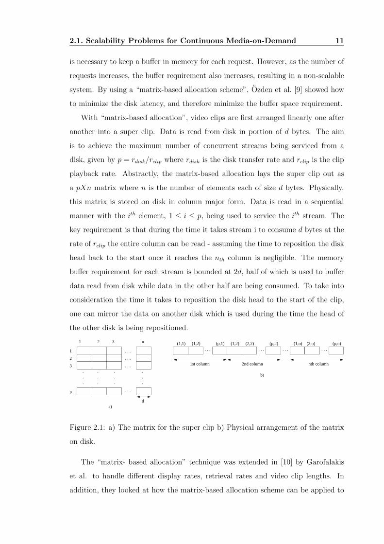
With “matrix-based allocation”, video clips are first arranged linearly one after
another into a super clip. Data is read from disk in portion of d bytes. The aim
is to achieve the maximum number of concurrent streams being serviced from a
disk, given by p = rdisk/rclip where rdisk is the disk transfer rate and rclip is the clip
playback rate. Abstractly, the matrix-based allocation lays the super clip out as
a pXn matrix where n is the number of elements each of size d bytes. Physically,
this matrix is stored on disk in column major form. Data is read in a sequential
manner with the ith element, 1 ≤ i ≤ p, being used to service the ith stream. The
key requirement is that during the time it takes stream i to consume d bytes at the
rate of rclip the entire column can be read - assuming the time to reposition the disk
head back to the start once it reaches the nth column is negligible. The memory
buffer requirement for each stream is bounded at 2d, half of which is used to buffer
data read from disk while data in the other half are being consumed. To take into
consideration the time it takes to reposition the disk head to the start of the clip,
one can mirror the data on another disk which is used during the time the head of
the other disk is being repositioned.
.
.
.
.
.
.
.
.
.
.
.
.
. . .
. . .
. . . . . . . . . . . .. . .
. . .
1 2 3
1
2
3
n
p
(1,1) (1,2) (p,1) (1,2) (2,2) (p,2) (1,n) (2,n) (p,n)
d
1st column 2nd column nth column
a)
b)
Figure 2.1: a) The matrix for the super clip b) Physical arrangement of the matrix
on disk.
The “matrix- based allocation” technique was extended in [10] by Garofalakis
et al. to handle different display rates, retrieval rates and video clip lengths. In
addition, they looked at how the matrix-based allocation scheme can be applied to

2.1. Scalability Problems for Continuous Media-on-Demand 12
different data layout schemes on disk, namely: clustering where entire clip is stored
on a single disk, and striping where each clip is de-clustered over all available disks
(similar to a RAID file system [8]).
In cases where multiple requests for the same clip differ by a small time interval,
system memory can be used to buffer data read from disk, saving subsequent disk
accesses. This technique was introduced by Kamath et al. in [11]. A heuristic was
developed for determining when buffer sharing is beneficial. The heuristic calculates
the threshold value T given by:
T = C ∗ (Mean Interarrival T ime ∗ Memory Size)/rclip (2.1)
Buffer sharing between two requests is only possible if the inter-arrival time,
tinter < T . The value of the constant C is derived via empirical tests. In [12], Shi
and Ghandeharizadeh showed that naive use of buffer sharing can in fact degrade
system performance by exhausting system memory. To avoid that problem they
also proposed a heuristic to calculate the threshold at which sharing is beneficial.
Their heuristic took into consideration the cost of disk bandwidth I/O and cost of
memory, but is independent of the arrival rate of requests and the access frequency
of each clip.
2.1.2 Optimizing Network Bandwidth
A different but simple approach to overcome the I/O problems is to keep the number
of requests to a minimum. This is achieved by broadcasting/multicasting popular
clips on multiple channels to all users on the network who can then individually
“tune” to the channel for their desired video clips. An increase in the number of
users in this case no longer results in an increase in the number of requests at the
server. The obvious disadvantage is that this service does not provide true video-on-
demand (VoD) because a user usually must wait until the scheduled broadcast time
in order to watch the video clip from the start. In the worst case, this wait-time can
be as long as the clip itself.
To reduce the maximum wait-time to a small fraction of the clip’s length, Viswanathan
and Imielinski [13] introduced “Pyramid Broadcasting” (PB) scheme. With PB,
2.1. Scalability Problems for Continuous Media-on-Demand 13
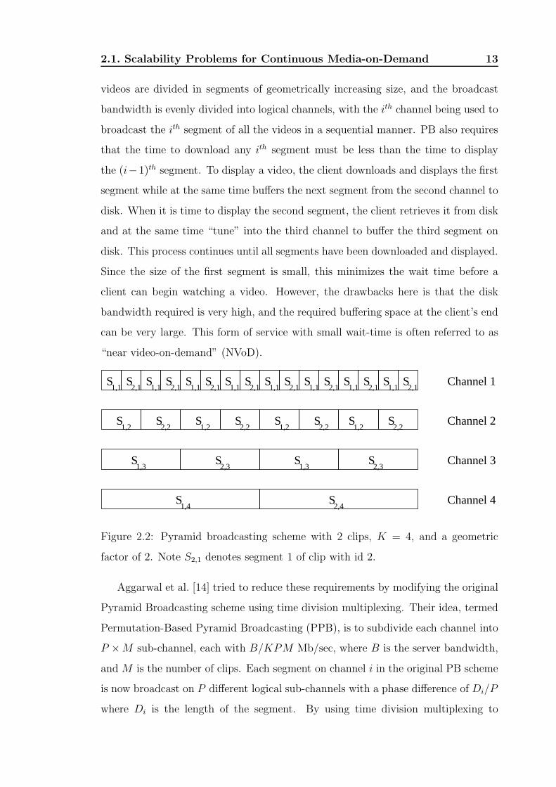
videos are divided in segments of geometrically increasing size, and the broadcast
bandwidth is evenly divided into logical channels, with the ith channel being used to
broadcast the ith segment of all the videos in a sequential manner. PB also requires
that the time to download any ith segment must be less than the time to display
the (i−1)th segment. To display a video, the client downloads and displays the first
segment while at the same time buffers the next segment from the second channel to
disk. When it is time to display the second segment, the client retrieves it from disk
and at the same time “tune” into the third channel to buffer the third segment on
disk. This process continues until all segments have been downloaded and displayed.
Since the size of the first segment is small, this minimizes the wait time before a
client can begin watching a video. However, the drawbacks here is that the disk
bandwidth required is very high, and the required buffering space at the client’s end
can be very large. This form of service with small wait-time is often referred to as
“near video-on-demand” (NVoD).
S2,1
S2,1
S S S
S S S S S S S
SSSS
S S
S1,1
S1,1
S1,1
S1,1
S1,1
S1,1
S1,1
SS2,1 2,1
S S2,1 2,1 2,11,12,1
1,2 2,2S
1,2 2,2 1,21,2 2,2 2,2
1,3 2,3 1,3 2,3
1,4 2,4
Channel 1
Channel 2
Channel 3
Channel 4
Figure 2.2: Pyramid broadcasting scheme with 2 clips, K = 4, and a geometric
factor of 2. Note S2,1 denotes segment 1 of clip with id 2.
Aggarwal et al. [14] tried to reduce these requirements by modifying the original
Pyramid Broadcasting scheme using time division multiplexing. Their idea, termed
Permutation-Based Pyramid Broadcasting (PPB), is to subdivide each channel into
P ×M sub-channel, each with B/KPM Mb/sec, where B is the server bandwidth,
and M is the number of clips. Each segment on channel i in the original PB scheme
is now broadcast on P different logical sub-channels with a phase difference of Di/P
where Di is the length of the segment. By using time division multiplexing to

2.1. Scalability Problems for Continuous Media-on-Demand 14
subdivide of the original channel into sub-channels with smaller bandwidth, the
disk space requirement at the receiving end is reduced. However, the complexity is
greatly increased since the client must now to tune to many different sub-channels
during playback. Hua et al. [15] also tried to improved on the original PB to
minimize disk space and I/O bandwidth requirements at the clients’ ends.
The disadvantage of PB and related schemes mentioned above is that they are
applicable to networks where there are dedicated broadcast channels. For wide-area
heterogeneous traffic networks where the bandwidth required for broadcasting is
too costly, IP multicast is designed to provide efficient group communication as a
low-level network primitive.
However, current IP multicast model has several serious problems making it
difficult to be employed for VoD application. The problems include small multicast
address space, lack of feasible admission control, difficulty in estimating group size
for billing, and lack of native support for handing system heterogeneity [16, 17].
Instead a new model termed EXPRESS (which is also known as single-source or
source-specific multicast) was proposed in [17] to overcome some of these problems.
The original multicast group idea was redefined with the concept of a multicast
channel identified by the tuple (S, E) where S is the source address of the sender and
E is a multicast address. The distribution tree rooted at the source can be easily
built using underlying unicast routing algorithm. EXPRESS uses a channel key
K(S, E) to provide authenticated subscription to the channel. The authentication
mechanism allows restriction on sender (i.e. only the source) and the receiver.
Furthermore, it allows ISP to estimate the size of the multicast since a router can
determine the size of the downstream portion of the multicast tree expressed as the
number of links. By identifying which links are being used for a particular multicast
channel, it allows the ISP to charge accordingly.
However, multicast is similar to broadcast in the sense that it requires that all
users subscribing to a multicast channel to receive the data at the same time. Thus
no savings can be made if two or more users request the same video clip but with
slightly different request times. Batching [18, 19] tries to minimize this problem
by grouping requests and serving them together at regular intervals. However, for

2.1. Scalability Problems for Continuous Media-on-Demand 15
batching to be effective, it requires a large interval leading to long wait times for
the users. Furthermore, batching can only provide NVoD type of service.
To provide true VoD, various techniques have been proposed using multicast as
the underlying transmission technique. One approach is stream aggregation which
tries to bridge the temporal skew between consecutive multicast streams for the
same video clip. This is achieved through rate adaptation where frames are selec-
tively dropped from the transmitting side and, at the receiver’s end, interpolation
techniques are used to compensate for the loss of frames. Whilst this technique
might be feasible for the image quality of the video stream, the sound degradation
is much more noticeable and often beyond the tolerance level.
A similar idea to stream aggregation is adaptive piggybacking [20,21] where the
bridging of the temporal skew is done by slightly speeding up the display rate of
the later stream while at the same time slowing down that for the earlier stream so
that they will eventually merge into one stream. This was based on a belief that the
viewer does not perceive small deviation of up to 5% from the actual display rate.
A more recent approach that utilizes the client’s disk space to minimize network
bandwidth was introduced by Hua et al. in [22]. With their method, termed patch-
ing, the first set of requests are serviced using a “regular” multicast. Subsequent
requests for the same clip are serviced immediately using a “patching” multicast.
However, rather than subscribing to only one multicast channel, the later clients also
subscribe to the nearest earlier “regular” multicast, using the “patching” multicast
for immediate display and buffering the data from the “regular” multicast on disk.
Once the buffered data is sufficient to bridge the temporal skew between the two
multicasts, the display data is fetched from the buffer and the “patching” multicast
is terminated.
Various patching schemes were proposed in [22] with the main difference being
the determination of where a new regular multicast should be started. In Greedy
Patching scheme, patching is initiated whenever there is an existing regular multi-
cast for the same clip currently active. This results in large buffer requirement at
the client’s end. In contrast, Grace Patching only starts a new regular multicast
whenever requests for the same clip differ by more than a threshold value T . An

2.1. Scalability Problems for Continuous Media-on-Demand 16
Video Server
Set Top Box 1
Set Top Box 3
Set Top Box 2
Pat
chin
g M
ultic
ast
Reg
ular
Mul
ticas
t
Buffer
Figure 2.3: Patching technique. Request times STB 1 < STB 2 < STB 3
optimal threshold T was derived in [23] to determine at what point a new regular
multicast should be started for later requests for the same clip. This value T takes
into account not just the client’s buffer size and the video length but also the request
rate of the video.
To make better use of client’s limited buffer space, Sen et al. introduced a new
algorithm called Periodic Buffer Reuse (PBR) [24]. In general, if the client’s arrival
time t from the last regular multicast is greater than B, the available buffer space
on the client’s disk, then patching could only be done with the last B frames of the
clip, leaving the buffer unused during the first L−B time of the clip where L is the
length of the video. With PBR, the buffer is reused in a periodic manner with the
server maintaining a schedule so that the client receives frames it+1, ..., it+B from
the regular multicast, while frames it + B + 1, ..., (i + 1)t are streamed directly to
the client.
A requirement of patching is that the client’s network bandwidth must be at least
twice the bit rate of the clip. This requirement was reduced by Eager et al. in [25].
They introduced a modified form of patching termed “bandwidth skimming” that
can be employed anytime the client’s bandwidth is greater than clip’s bit rate - the
extra bandwidth is referred to as the skimmed bandwidth. To address the issue of
packet loss recovery, Mahanti et al. extended the work on bandwidth skimming as

2.1. Scalability Problems for Continuous Media-on-Demand 17
well as PB for broadcast network, to produced Reliable Bandwidth Skimming and
Reliable Periodic Broadcast protocols in [26].
An important point to note is that common to all of the above techniques - PB,
patching, and bandwidth skimming - the clients are required to possess large buffer
space and the bandwidth in their “last-mile” connection needs to be greater than
(and in most cases at least twice) the clip’s playback rate.
In contrast, the technique that we present in this dissertation allows greater
bandwidth saving through multi-level network buffering, and reduces the client’s
required last-mile bandwidth to be the same as the clip’s playback rate.
2.1.3 Video Streaming with Application Layer Multicast
After a decade since its initial proposal, IP multicast is still plagued with con-
cerns pertaining to scalability, network management, deployment and support for
higher layer requirements such as error, flow and congestion control [17]. Research
in the last few years has concentrated in end-system overlay approaches that can
efficiently and robustly support all multicast related functionality including mem-
bership management, packet replication and routing. With these approaches, mul-
ticast is performed at the application layer without requiring any additional router
modifications; hence they simplify adoption and increase application flexibility.
Generally, these approaches require self-organizing and self-improving protocols
that can construct an overlay network on top of a dynamic, unpredictable and
heterogeneous Internet environment without relying on a native multicast medium.
Multicast mechanisms are then performed between end applications by constructing
multicast tree, and packet replication. Overlay networks possess a number of inter-
esting properties: incrementally deployable, adaptable, robust, customizable. Over-
lay networks, however, must address: management complexity, real world (problems
with NAT, firewalls), inefficiency as code running in routers, information loss.
A recent work which aims to utilize an overlay network for application layer
multicast of on-demand live data is the Overcast system [27]. The goal of Overcast
is to build a “deep” distribution tree rooted at the source using a simple distributed
tree building algorithm that can quickly adapt to changes in the underlying network

2.2. Network QoS for Continuous Media-on-Demand 18
fabric and maximizes bandwidth to the root for all nodes.
2.2 Network QoS for Continuous Media-on-Demand
2.2.1 Differentiated Services and Integrated Services Archi-
tecture
Today’s Internet is pervasive and ubiquitous, but, due to its undifferentiated and
unpredictable service responses, it is unable to support many critical applications
with stringent quality of service (QoS) requirements. The next wave of innovations
for an Internet-based global network will be mainly driven by users who are willing to
get premium quality service for audio or video communications, or for transactions
such as stock trading and interactive games. These innovative applications require
the support of QoS.
The Integrated Services (IntServ) [28] and Differentiated Services (DiffServ) [29]
architectures have been proposed by the Internet Engineering Task Force (IETF)
to address the QoS issue. The goal of IntServ is to allow end-to-end QoS to be
provided to applications.
The IntServ architecture employs a per-flow Resource reSerVation Protocol (RSVP)
[30] and rate-based scheduling algorithms such as Weighted Fair Queueing (WFQ)
[31] and Self-Clocked Fair Queueing (SCFQ) [32] to provide QoS service guarantees
to individual flows. Per-flow classifications are based on source/destination IP ad-
dresses and port numbers. The resource requirements for running per-flow resource
reservations on routers increase in direct proportion to the number of separate reser-
vations that need to be accommodated. This model is considered too complex, and
not scalable enough to be used in the high-speed core of the Internet.
DiffServ proposes a scalable service discrimination model without requiring per-
flow state management in the core network. DiffServ focuses primarily on aggregate
flows and differentiates between service classes rather than providing absolute per-
flow QoS guarantees. DiffServ networks classify packets into a small number of
aggregate flows or “classes”, based on the DiffServ codepoint (DSCP) in the packet’s
2.2. Network QoS for Continuous Media-on-Demand 19
IP header. Core routers (routers inside the DiffServ domain) only have to keep state
information for a small number of classes.
The central idea of the DiffServ is to mark packets into a small number of classes
at the edge of the network according to their service level agreement and then treat
them appropriately at the core nodes according to its class.
In DiffServ architecture, the edge routers deploy mechanisms to classify, monitor
and tag packets into different classes and then police the arriving packets according
to the service profiles. The interior routers do not need to keep per-flow state, they
only need to distinguish among relatively few classes of packets and give different
treatments to different classes of packets. The packets of a flow that obey the service
profile are marked IN (in profile) and the packets that are beyond the service profile
are marked OUT (out-of-profile). The network gives preference to IN packets while
dropping OUT packets disproportionately at the time of congestion. The service
profile represents the user’s expected services from the network; it does not describe
a strict guarantee, but rather an expectation. DiffServ architecture expects to use
different drop precedence to achieve service differentiation.
Through aggregation, the Differentiated Services architecture offers excellent
scaling properties, but it does not guarantee end-to-end QoS for individual applica-
tion. The architecture lacks a standardized admission control scheme, and does not
intrinsically solve the problem of controlling congestion in the Internet.
Quoting RFC 2990 [33], “the outcome of the considerations of these two ap-
proaches to QoS architecture within the network is that there appears to be no
single comprehensive service environment that possesses both service accuracy and
scaling properties.” A framework for IntServ operation over DiffServ networks has
been proposed to provide both scalability and end-to-end QoS [34]. For this in-
tegration framework to be realized, mechanisms for conveying information about
resource availability in a DiffServ network region (from core routers) to bound-
ary/edge routers and some form of signalling from the boundary/edge to the client
application must be developed. It is also recommended in [33] that an admission
control function be defined that can determine whether to admit a service differen-
tiated flow along the nominated network path. Our Enhanced DiffServ architecture

2.2. Network QoS for Continuous Media-on-Demand 20
tackles this issue.
We describe below some recent international progresses in the field and relate
them to our work.
De Meer et al. [35] provide an analysis of existing IP quality of service solutions
and the implied signalling issues. It is pointed out that an improvement to the
QoS DiffServ architecture could be achieved by providing congestion signalling from
within a DiffServ domain to the boundary between the two administrative domains.
We address these issues in Chapter 7.
In Endpoint Admission Control (EAC) [36], the explicit decisions whether to
accept or refuse a connection request were taken by edge devices, rather than by
devices within the network. The driving idea of EAC schemes is to convey the
congestion status of network nodes to the end-points. The idea is sound but may
not be adequate to control the connection’s QoS. Our approach employs feedback
information explicitly from both the endpoints and the core routers.
Bianchi [37] suggests a solution in which a DiffServ channel is always associated
with a probing channel of the same class but at a lower priority. If packets on
the probing channel make it to the egress router of the DiffServ region and back to
ingress router, the region is deemed not congested. The idea is to push traffic control
to the edge and to base the connection requests acceptance/refusal on packet loss
detection. A drawback of the approach is that the feedback may not be adequate
to allow an edge device to control the QoS measure tightly. The study also raises
the case for defining a new “paired” PHB in the DiffServ architecture.
Gerla, Weng and Lo Cigno [38] consider bandwidth feedback control of TCP and
real time sources in the Internet. However, the control is in-band and may interfere
with the operation of the routers. Our feedback loop operates on a per-class basis
and utilizes active mechanisms on the router’s control plane and avoids interferences
with the forwarding operation of conventional routers.
Hjalmtysson [39] describes a control-on-demand model for programmable net-
works. This model allows the installed control programs to exploit lower-level facil-
ities, in particular hardware facilities. Through filtering and frame peeking, control
programs can inspect “flows” or “aggregate” or “control” stream of interest and
2.2. Network QoS for Continuous Media-on-Demand 21
then extract the required information for intelligent control. Our approach can
be implemented either by integrating the control mechanism in the router itself or
implemented as a control process running on the control plane of a router.
2.2.2 Active and Programmable Networks
The Active Networks (AN) research program [40] has the goal of producing a new
network platform flexible and extensible at runtime to accommodate the rapid evo-
lution and deployment of network technologies and services. Active Networks tech-
nologies [40] expose a novel approach that allows customer value-added services to
be introduced to the network “on-the-fly”. Typically, through the Active Networks,
applications can deploy new protocols and change or modify their services dynami-
cally for specific purposes in terms of active packets. Network service providers and
third parties can program the network infrastructure to provide value-added services
and applications.
Traditional network nodes (e.g. routers on the Internet) enable end-system con-
nectivity and sharing of network resources by supporting a static and well-defined
set of protocols. In contrast, the Active Networks approach allows the applications
themselves to define the services provided by the network.
A general architecture for Active Networks specifies a three-layer stack on each
active node [41]. At the lowest layer, an underlying operating system (NodeOS)
abstracts the hardware and provides low-level resource management facilities such as
a node’s communication, memory, and computational resources among the various
packet flows that traverse that node. At the next layer, one or more execution
environments (EEs) provide the basic application programming interface API for
writing active applications. At the topmost layer are the active applications (AAs),
each of which contains code injected into the network to support a network service.
A number of active networks prototypes have been developed [42] to study
whether active networks can deliver their claimed benefits in terms of new and
novel services, while at the same time keeping the network efficient and secure.
Recent DARPA Openet [43] is a programmable networking platform for injecting
network services dynamically to networks. Openet consists of a distributed archi-

2.2. Network QoS for Continuous Media-on-Demand 22
tecture, an Open Runtime Environment (ORE), a service hierarchy with essential
services, a management part and a development kit.
The Openet architecture has been developed to support the dynamic introduc-
tion of application services that can apply active network control and alter packet
processing. A chief goal of Openet is to build a network programming platform for
service deployments on a commercial-grade network device (e.g., a router, a switch,
a firewall).
To preserve the hardware fast-path for data packets, Openet introduced the
Active Flow Manipulation (AFM) enabling technology [44]. The AFM mechanism
involves two abstraction levels in the control plane. One is the level at which a
node can aggregate transport data into traffic flows, and the other is the level at
which it can perform simple actions on the traffic flows. The abstraction allows one
to think and act in terms of primitive flows whose characteristics can be identified
and whose behaviors can be altered by primitive actions in real-time. With AFM,
customer network services can exercise active network control by identifying specific
flows and applying particular actions thereby altering network behavior in real-time.
These services are dynamically deployed in the CPU-based control plane and are
closely coupled with the silicon-based forwarding plane of the network node, without
negatively impacting forwarding performance.
To leverage existing active networking research efforts, Openet implemented a
layer over which existing active network implementations can be ported. A run-time
environment, termed Oplet Run-time Environment (ORE), provides for security and
service management over which existing execution environments (EEs) can be run
as network services. Openet provides support for EEs by running an embedded
virtual machine (Java VM, in this case) in the control plane of the network device,
and by creating a Java-compatible interface to the low-level hardware. A Java
Forwarding API provides access to the low-level hardware. The Forwarding API
realizes the AFM [44] technology and provides interfaces for applications to control
a generic, platform-neutral forwarding plane. Using the Forwarding API, customer
network services access the AFM technology to exercise active network control by
identifying specific flows and applying particular actions thereby altering network

2.2. Network QoS for Continuous Media-on-Demand 23
behavior in real-time, such as setting packet filters, changing the forwarding priority;
and provide new protocol support. Figure 2.4 depicts the Openet architecture [44].
Figure 2.4: Openet Architecture
This thesis considers the use of the Openet-Passport Router platform to intro-
duce active control mechanisms.
2.2.3 Pricing for DiffServ
Despite the IntServ and DiffServ work, the deployment of these architectures to pro-
vide end-to-end QoS has been negligible in the real world since neither IntServ nor
DiffServ alone provides the answer. IntServ can support end-to-end QoS but is not
scalable, and DiffServ is scalable but cannot guarantee end-to-end QoS for applica-
tions. It is increasingly recognized that the critical problems blocking deployment
of QoS architectures are more ones of economics (pricing), policy, industry structure
and tradeoffs among competing players.
One of the most commonly used approaches in traffic engineering is to create
an optimization model and find the optimal price for the use of network resources.
Most of the techniques with this approach either assume a well-known user utility
function or user demand function and establish an optimization model to maximize
2.2. Network QoS for Continuous Media-on-Demand 24
either the social welfare or provider’s revenue.
In [45], Kelly laid out overall optimization problem for a network, that is maxi-
mizing total user utility. He divided the overall system problem into sub-problems
of surplus maximization for the user and revenue maximization for the provider.
He showed that network service prices can be used as Lagrange multipliers between
the user’s and provider’s problems. Kelly and his co-workers, in their analysis, used
logarithmic utility functions for users. They proved that optimal rate allocation will
be weighted proportional fair when users have utility function of form
u(x) = w ∗ log(x) (2.2)
where w is weight and x is sending rate of the user. This approach can be
formally stated as follows. Let R denote the set of users. Let Ur(x) denote the
utility function of a user r using r using x network resources, and Cr(x) the cost
of user r using x network resources. Let Rr(x) denote the revenue generated by
user r using x network resources and Cp(x) the cost of service provider providing
x network resources. Then the problem is modelled by the following optimization
systems:
From the User’s Perspective:
Maximize:∑
r∈R
(Ur(x) − Cr(x)) (2.3)
subject to: Ax ≤ C (2.4)
over x ≥ 0 (2.5)
From the Provider’s Perspective:
Maximize:∑
r∈R
(Rr(x) − Cp(x)) (2.6)
subject to:∑
x ≤ C (2.7)
where A is an 0 − 1 matrix that defines the subset of resources used by users,
and C denotes the total capacity.
Low et al. [46] generalized the concepts to users with concave utility functions,
not necessarily logarithmic. They provided a family of distributed pricing algorithms
2.2. Network QoS for Continuous Media-on-Demand 25
that optimizes the network with users having logarithmic or non-logarithmic concave
utilities.
Since pricing itself is an economic problem, an interesting approach in this cat-
egory is to create an auctioning environment and let users bid for the use of the
network resources. In [47], a second-price auctioning model was used in the net-
work where each packet carries a bid in its header. The transmitted packets will be
charged for the market-clearing price rather than the actual bid where the market-
clearing price is the highest rejected bid. In their model, the network is decomposed
hierarchically into subnetworks and each subnetwork is abstracted into a single bot-
tleneck capacity. In order to provide a particular class of service to users, this service
class will compete not only for the resources locally with other service classes inside
the subnetwork but also for the resources in the neighboring subnetworks. Although
auctioning does not require a priori knowledge of the user traffic characteristics and
has been generally considered as the one that achieves economic efficiency, there is
significant implementation overhead with this strategy.
Although there have been many optimal pricing approaches proposed in the
literature, these two general models above show the basics in most of them. The
differences among the existing approaches lie in the different models used to compute
Ur(x), Cr(x), and Rr(x), the set of constraints incorporated in the optimization
models, or the mechanism used to solve the optimization problem.
Many utility function Ur(x) and cost functions Cr(x) have been proposed. One
commonly adopted utility function is the logarithmic utility function as used in [48].
The cost function is usually a function of the price and the utilized resources f(p, x).
The solution of this kind of model is the optimal price that maximizes the social
welfare (or surplus).
The demand functions are usually modeled as a decreasing function of the price
and the objective is to find the optimal price that maximizes the provider’s revenue
or profit. Notice that the provider’s cost of providing all resources∑
Cp(x) is some-
times considered as a constant, thus the revenue maximization model is equivalent
to the profit maximization model.
Another trend is to model the interaction among users and service providers

2.2. Network QoS for Continuous Media-on-Demand 26
(through pricing and resource allocation) as either a cooperative or a non-cooperative
game and use game theory to analyze the system. Example approaches can be found
in [49].
Last but not the least is the Quality of Service aspect. Since price is such an
important economic incentive to users, it is often considered as an effective mecha-
nism for traffic management. Indeed, many proposed pricing schemes entail either
congestion control or admission control or even both. The relationship between
pricing and these two traffic management functions is discussed. Several approaches
assume that users are rational regarding the price signals and use the pricing as a
main mechanism for congestion control. When congestion occurs, extra costs are
charged in order to address the externally issue. Since users are expected to react
to the price signals, congestion-sensitive pricing schemes often emphasize user adap-
tation where users adjust their sending rate in case of congestion or price change.
Some approaches that fall into this category can be found in [48, 50, 51].
However, whether the optimal price is achievable in practice is still under debate.
For example, Shenker et at. [52] argue that utility functions could not be well defined
in short-term and sometimes even very difficult in a long-term time scale. Therefore,
the effectiveness of such schemes is still questionable. Additionally, most congestion-
sensitive pricing do not address the scalability issue. Most of them need core routers
involvement to collect all the required information and perform resource allocation.
To preserve the scalability of DiffServ, in this thesis, we examine the edge-aware
resource discovery which only involves the edge routers. Secondly, if the congestion
state is beyond the congestion threshold, the price will be increased exponentially;
if the congestion state is below the congestion threshold, the price will be decreased
linearly or be stable. What we want is to avoid congestion, not to act after the
congestion occurs. A proactive approach is preferred to a reactive approach in this
case.
Admission control is traditionally performed on a hop-by-hop basis [53]. Each
intermediate network element along the path has to decide whether the new request
can be accommodated or not and reserves resources accordingly. However, if admis-
sion control were to be added to all the core routers, this would violate the DiffServ

2.2. Network QoS for Continuous Media-on-Demand 27
principle of leaving the core simple.
Edge/end-point admission control that pushes the admission control functional-
ity to the edge of the network seems more suitable in this case and has a number
of advantages over the hop-by-hop approach such as faster response time and less
implementation overhead. The admission decision is then made based on this feed-
back information. A comprehensive study on end point admission control can be
found in [54]. Our approach falls into this category.
Up till now, there has been little research using price as a primary admission
criterion. In [55], the authors suggest that the admission decision could be made
based on the user’s willingness to pay for the ECN mark. However, it is not very
clear how users should pay for the marking.
In [48], Wang et al. presented a comprehensive pricing framework and a signaling
protocol that integrates the admission control, congestion control, and pricing for
DiffServ networks. However, their focus was mainly on the congestion-sensitive
pricing and do not study the admission control sufficiently. Admission control in
their framework is performed hop-by-hop and is independent from pricing.
In general, the work cited above differs from ours in that it does not enter into de-
tail about the communicating process and the network architecture and mechanisms
for collecting the locally computed prices. Some of the work also assumes immediate
adjustment of the price in response to the network dynamics, or require the user to
maintain a static demand until a optimal price is found, which is not practical. Our
work is concerned with developing a practical and general framework for resource
discovery, pricing and evaluating the performance benefits of congestion-sensitive
pricing and adaptation through simulations. Our work can therefore be regarded as
complementary to some of the cited work. Our architecture shares the same idea
but also differs in edge admission control. These will be discussed in chapter 8.

Chapter 3
Framework for Scalable
Continuous Media-on-Demand
In an ideal system from the end-user’s perspective, there would be a dedicated
stream allocated for each user on-demand. The stream would need to have suffi-
cient bandwidth to support the required bit rate of the multimedia clip being sent
across the network. Additionally, a dedicated stream would mean that VCR-like
functionalities such as fast forward, fast rewind and pause can also be supported.
However, building such a system that is scalable is beyond the capabilities of today’s
operators. Scalability for multimedia networks has long been a problem despite the
increasing growth in bandwidth capacity, processing power and storage capacity The
problem shows itself at different stages within the delivery system.
For the video server, there is a limit to the number of multimedia streams that
it can deliver. While storage capacity has increased exponentially over the year,
and disk transfer bandwidth has improved with new technologies such as Redun-
dant Arrays of Inexpensive Disks (RAID) [8], disk seek time has remain relatively
unchanged. It is this last factor which prevents supports for large number of concur-
rent users. Storage technologies which have minimal seek times such as flash disks
are too small and expensive for storing multimedia clips.
A similar problem exists with the bandwidth requirement. While it is true
that core network bandwidth has increased exponentially over the years, it is still
not possible to support a large number of concurrent users if each one requires a
28

3.1. Delayed Multicast 29
dedicated stream from the server. The nature of many multimedia streams where
large amount of bandwidth is required per stream, also places a limit on how many
streams can be serviced by the operator.
It can be seen that the two problems outlined above can solved if the number of
concurrent requests does not grow linearly with the number of users but is instead
kept relatively constant. Fewer requests would mean fewer streams from the server
and therefore I/O issues arising from seek time would not be a problem. Similarly,
the bandwidth required by the server to service all the clients would also not be as
great.
The purpose of this chapter is to present a new framework for multimedia de-
livery that tries to achieve the main objective above: to reduce the number of re-
quests serviced by the server. A feasibility study of the new framework is presented
through the use of a prototype. The cost-effectiveness of the system is demonstrated
by showing how the prototype is assembled from common off-the-shelves (COTS)
components rather than specialized hardware.
3.1 Delayed Multicast
An important observation in many video-on-demand (VoD) systems is that many
requests are for the same content. This fact is confirmed in a recent study by Yu et
al. [56] which examined user behaviors on a large scale video distribution system.
The need to conserve bandwidth when distributing the same information to mul-
tiple receivers was recognized back in the late 1980s when Steve Deering proposed IP
Multicast [57]. The idea is to use a protocol, Internet Group Management Protocol
(IGMP) [57, 58], to setup and maintain a shared tree paths between users who are
interested in the same content being delivered. For each link in the tree, only one
copy of the data needs to be sent thus saving bandwidth if multiple clients share
the same link in the path between the sender and receivers. It is the responsibility
of routers at fan-out points in the tree downstream from the source to replicate and
forward copies of the data to clients further down the transmission path. A survey
of IP multicasting and the MBone architecture is presented by McCanne in [59].

3.1. Delayed Multicast 30
However, there are many obstacles which prevents wide scale adoption of IP
Multicast [17]. These problems include:
• Lack of access control. IP Multicast does not specify a mechanism for limiting
who can receive and send on the multicast channel.
• Large routing table if multicast is to be used over a large network.
• Limited address space, and problematic address allocation.
When it comes to multimedia delivery on-demand, there is another factor which
makes IP Multicast ill-suited for this purpose: it requires all users to receive data
almost at the same time (taking into consideration the additional network delays).
There is no way for a user to specify a later time to receive the content, contradicting
the requirement of “on-demand” delivery.
To address the above problems, we propose a novel architecture, termed “Delayed-
Multicast” to address the network bandwidth and server load problem. The mo-
tivation stems from the fact that processing power, disk and memory storage are
relatively cheap in comparison with network bandwidth. We believe that by uti-
lizing (and possibly increasing) existing computational resources such as processing
power, memory and disk at internal nodes in the path from the server to the users,
we can increase the number of users that can be served by the system, yet at the
same time minimize core network traffic and system load.
Delayed Multicast is similar to traditional multicast in the sense that a transmis-
sion tree rooted at the server is required for the delivery of data. However, instead
of simply replicating data and forward it at fan-out points, a buffer is used to bridge
the time difference between an earlier request and a later request, hence the name
Delayed Multicast.
The idea behind the Delayed Multicast is illustrated in Figure 3.1 where four
requests for the same movie are made to the video server but with different starting
times. In the figure, the arrows represent the network links and the label next
to each arrow represents the bandwidth requirement (expressed as the number of
transmitting streams on that particular link). Traditionally, the server will need
four transmission streams to service each request as seen in Figure 3.1(a). However,

3.2. System Architecture 31
if the starting times are known in advance, the bandwidth requirement from the
video server to the intermediate router can be reduced to just one stream. This is
achieved by buffering data packets from the leading stream - the stream with the
earliest starting time - at the intermediate router and by forwarding them on at the
appropriate time. This is illustrated in Figure 3.1(b). The numbers above the slots
represent the offsets from the front of the buffer, measured in minutes for simplicity.
Server
(minutes)
RouterIntermediate
StartingTimes
1 11 1
Requests
4
= 9S 4S 1 S 2 = 8S 3
R R 2 R R 4 1 3
= 0 = 2
a)
1
S 4= 0S 1 = 2S 2 = 8S 3
R R 2 R R 4 1 3
= 9
b)
2... 9 min buffer
98
Figure 3.1: Demonstration of Delayed Multicast
The scalability of Delayed Multicast is evident when we extend the simple topol-
ogy in Figure 3.1 to a more realistic topology consisting of many intermediate routers
as shown in Figure 3.2. In such situations, the video server cannot possibly service
all requests individually and late requests must be rejected or delayed until earlier
requests have been serviced. However by employing Delayed Multicast, only one
stream is needed from the server to the intermediate router in order to service each
client.
3.2 System Architecture
Ideally, employing “Delayed-Multicast” at every router in the network hierarchy
would provide the maximum savings. This would not be feasible in practice due to
factors such as costs and the increased latency. A more realistic scenario is presented
in Figure 3.3b) where routers employing “Delayed-Multicast” protocol (DMP) are
sparsely placed at key positions in the path from the servers to the clients. Examples

3.2. System Architecture 32
S= 0
1R
1 = 9S 4S 2 = 8S 3
R 2 R R 4 3
= 2 S n
R n
= y
IntermediateRouters
StartingTimes
Requests
Server
Figure 3.2: Delayed Multicast in Extended Topology
of placement positions are at the video server level to reduce the load, and at the
community server at the last-mile network to reduce bandwidth consumption.
MAN
MANOC−12
OC−12
Head−Ends
.Users
Users
........... ......................
......................
.................
DMP Router
Router
Client
Video Server
Core Network
Video Server
OC−48
OC−48
a) b)
Figure 3.3: a)Current hierarchical network infrastructure. b)Sparsely placed DMP-
enable routers in the transmission paths from the video server to the clients.
Currently, the two most common technologies being used for the consumer broad-
band in the last-mile network are hybrid/fiber cable (HFC) and Digital Subscriber
Line (DSL). The important factor, from the point of view of multimedia distribu-
tion, is that both technologies in their current forms have sufficient bandwidth to
support video streams of at least VHS quality using appropriate compression tech-
niques. Another important factor is that there are points in most of these networks
where many users share the same upstream link to the wider Internet. For cable, this

3.2. System Architecture 33
could be the neighborhood head-end while for DSL, this can be the local exchange
where the Digital Subscriber Line Access Multiplexer (DSLAM) is installed.
An issue which needs to be addressed is how can DMP be introduced at the
router. One approach is to utilize the processing power and buffer capacity of the
router to run DMP. However, a major problem with such an architecture is the effect
on the router’s switching rate. By requiring the router to filter for DMP traffic, and
then process the data, it will drastically reduce the switching performance. This
is further emphasized in a high speed network where the bottlenecks lie at the
routers rather than the links’ transmission capacity. Another problem is the lack of
sufficient processing power and buffer capacity in current routers, and there is no
easy or cost-effective ways to increase these resources.
For the above reasons, we present a new architecture for a DMP-enabled router,
illustrated in Figure 3.4. The task of performing Delayed Multicast is shifted from
the router to dedicated machines, termed video gateways, which are grouped to-
gether. The gateways are connected via high speed links, eg. dedicated 100Mb/sec
or even Gigabit Ethernet, to the router. The video gateways are simple PCs made
from cheap off-the-shelf components.
BackboneNetwork
RouterGateway Controller
Switch/Hub
DMP Router
Video Gateway
Video Gateway
Video Gateway
Figure 3.4: DMP Router Architecture
Each group of gateways is managed by a gateway controller. Its role is to handle
control information, “Delayed-Multicast” Control Protocol (DMCP), which decides
the placement and size of buffers created on each video gateway. The controller

3.2. System Architecture 34
makes its decision based on information it maintains about gateway resources and
bandwidth availability on links connecting to the router.
The video-gateway takes its instructions from the controller and runs the “Delayed-
Multicast” Protocol (DMP). The basic tasks of DMP is allocating buffers, receiving
data from its peer upstream, buffering the data and transmitting the data at the
required time to its peers downstream.
By offloading the operations of DMP and DMCP to dedicated machines, the
router switching performance is greatly improved since it does not have to differen-
tiate each incoming packet and perform the extra processing associated with DMP
traffic. It also removes the need for expensive upgrading of internal router’s memory
and processing power. These factors allow DMP to be integrated into existing net-
works employing traditional routers. Scalability is also helped by the use of cheap
standard components in assembling video gateways. As the load increases, more
video gateways can be easily added to the cluster.
In terms of cross-traffic, it is unlikely that this would pose a problem. It is
assumed that this network is one which has been designed with sufficient capability
for the delivery of multimedia. As such, the routers being deployed should be able
to handle the switching requirements for multimedia traffic; typically done in the
hardware at wire speed. Furthermore, it is expected that multimedia traffic will
have “better-than-best-effort” quality of service (QoS) so heavy cross-traffic should
have little impact on the performance of multimedia delivery. A more detailed
examination of issues with network QoS is presented in Chapters 7 and 8.
Other components in our VoD architecture are the video server, and the client’s
set-top-box (STB). The roles of the video server and the STB are similar to that
of the traditional video server and STB, and their design and implementations for
optimal performance is outside the scope of this dissertation. The only requirement
is that they use DMP for requesting, sending and receiving data.

3.3. Delayed Multicast Protocol 35
3.3 Delayed Multicast Protocol
The main goal of DMP is to facilitate the setup and tear down of DMP sessions,
and the scheduling of the transmissions. A DMP session consists of the following:
• A buffer of a predefined size.
• A parent (the peer session which is sending the data),
• A list of children (peer sessions which receive data from this DMP session)
with their respective offsets in the buffer.
The basic operations are described in Figure 3.5. These operations are performed
on a round basis and the time between rounds, referred to as the round period, is de-
termined from two factors: the message size being used and the bit rate requirement
for the stream. We examine these factors in Section 3.4.2.
It is important to note that DMP does not specify the resource scheduling al-
gorithm being employed. Instead, that task is left to a scheduling layer which
determines the topology for the transmissions, and the buffer space required for
each DMP session.
DMP layer sits above the network transport layer so that it can make use of
the services offered by the lower layers without having to worry about issues such
as fragmentation and reassembly of messages. This also means that DMP can use
a different network transport protocol with minimal changes. Thus, although for
our prototype, we have developed for use with only unicast, it should be possible
for DMP to be extended to utilize lower layer multicast. This would be suitable in
cases where native multicast is available and there are multiple clients requesting
the same clip at the same time.
The design decision to separate DMP from the resource scheduling was made so
that it would be easy to install different scheduling algorithms without the need to
modify the underlying operations of DMP. As a result, one of the goals in designing
DMP is to make the set of services it offers as flexible as possible to facilitate
new scheduling algorithms. This gives rise to two sets of signaling messages: one
for the interaction between the scheduling layer and the other for the peer-to-peer
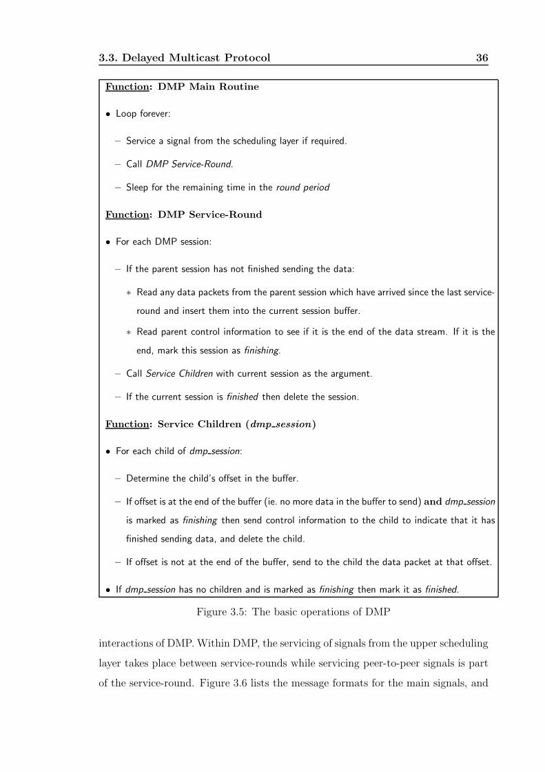
3.3. Delayed Multicast Protocol 36
Function: DMP Main Routine
• Loop forever:
– Service a signal from the scheduling layer if required.
– Call DMP Service-Round.
– Sleep for the remaining time in the round period
Function: DMP Service-Round
• For each DMP session:
– If the parent session has not finished sending the data:
∗ Read any data packets from the parent session which have arrived since the last service-
round and insert them into the current session buffer.
∗ Read parent control information to see if it is the end of the data stream. If it is the
end, mark this session as finishing.
– Call Service Children with current session as the argument.
– If the current session is finished then delete the session.
Function: Service Children (dmp session)
• For each child of dmp session:
– Determine the child’s offset in the buffer.
– If offset is at the end of the buffer (ie. no more data in the buffer to send) and dmp session
is marked as finishing then send control information to the child to indicate that it has
finished sending data, and delete the child.
– If offset is not at the end of the buffer, send to the child the data packet at that offset.
• If dmp session has no children and is marked as finishing then mark it as finished.
Figure 3.5: The basic operations of DMP
interactions of DMP. Within DMP, the servicing of signals from the upper scheduling
layer takes place between service-rounds while servicing peer-to-peer signals is part
of the service-round. Figure 3.6 lists the message formats for the main signals, and

3.3. Delayed Multicast Protocol 37
their corresponding responses.
NACK
NACKConnect SID PID PAddr Delay ACK
NACKResize SID Size ACK
NACKSplit SID PointA SizeA PointB SizeB ACK NSID
NACKConnect SID PID Delay ACK
Disconnect
Finish
SeqNum Data
and session objectsSignals between peer DMP protocol
Create Size
Success Reply
ACK SID
Failure Reply
Data Message Format
Signals from Scheduling Layer to DMP
Figure 3.6: Signal and data message formats
The semantics of each message are described below:
• Create - The scheduling layer indicates to DMP to create a new session with
buffer of size Size. If successful, a new session is created with a unique SID.
DMP maintains a reference to it via a hash-table which maps SID to the
session. The SID is returned to the scheduling layer.
• Connect - Can be sent from either the scheduling layer to DMP or between peer
DMP sessions. In the first case, the scheduling layer is telling DMP session SID
to connect to the parent session identified PID and its host address PAddr.
The Delay is the offset required in the parent’s buffer. After receiving this
message from the scheduler, DMP strips the PAddr field to determine the
parent host address. It then sends the same Connect message to the parent
session. The SID is used by the parent session to identify the child session.
If this succeeds a direct link between the child and the parent sessions would
have been set up.
• Resize1 - The scheduling layer tells DMP to resize the buffer of session SID to

3.3. Delayed Multicast Protocol 38
the new size Size.
• Split1 - The scheduling layer tells DMP to split the session SID into two
sessions. The buffer of the original session is divided into two smaller buffers
of size SizeA and SizeB starting from PointA and PointB respectively. The
first session keeps the original parent session but the second session will need
to be specified a new parent via the Connect signal. A new session ID NSID
is created for the second session and this is returned to the scheduling layer.
• Finish - Control message sent from the parent session to the child session to
indicate the end of the stream.
• Disconnect - Sent from the child session to the parent session to indicate that
it no longer wishes to receive data.
• Data - Data messages which are sent between DMP sessions. The SeqNum
field is a number which indicates the position of this message with respect to
the video stream. The DMP data traffic will be addressed directly to the video
gateway from the parent.
To illustrate how the signaling is used, we will go back to our sample scenario.
Requests for a particular movie session are collected at the scheduling layer which
uses that information to determine an optimum schedule. The schedule specifies the
nodes where DMP sessions are needed (ie. the topology for the transmission tree),
and how much buffer space each session requires.
The scheduling layer uses the CREATE signal to create the required sessions
according to the schedule. The creation time for the sessions will be different de-
pending on when each session is supposed to start receiving data, but a parent
session will always be created before its child sessions. The scheduling layer follows
the CREATE signal with a CONNECT signal specifying the ID of the parent ses-
sion and the required delay. The actual connections are made by the DMP sessions
sending CONNECT signals to their parents.
1Resize and Split signals are used by the scheduling layer to dynamically manage buffer and
bandwidth resources.

3.4. System Prototype and Evaluation 39
At each node where there is an active session, DMP performs its service-rounds
reading data from the parent session and forwarding to its children the data at the
required offset. When the server has finished transmitting the required clip, it sends
a FINISH signal to all of its children. Each child session then goes into the finishing
state sending a FINISH signal to each of its children after they have been sent all the
data in the buffer destined for them. This continues down till it reaches the leaves
of the tree, at which point all clients should have received their requested clip.
A scenario where the RESIZE signal can be used is when the priori knowledge
of the requests are not known. Consider the example in Figure 3.1(a) where after
2 minutes, another request arrives. A new stream must be started from the server
to handle the request. However, at the same time the scheduling layer can make a
RESIZE call to the DMP session servicing the first request to change its buffer size
such that it will be able to hold at least 2 minutes of data. After 2 minutes, the
second request can then switch to the session serving the first request and free up
the bandwidth on the path from the server to the intermediate node. Subsequent
requests can be served in a similar manner by extending the session’s buffer size.
Lastly, the SPLIT signal can be applied in situations where we wish to make
use of the available bandwidth in order to minimize the memory requirement at a
particular node. An example of this is turning Figure 3.7(a) to that of Figure 3.7(b)
when extra bandwidth becomes available and one wishes to minimize the buffer
space utilization.
3.4 System Prototype and Evaluation
To evaluate the feasibility DMP, we have built a prototype using a Linux system
running on a standard PC system. This was chosen because it is a quick and flexible
way to develop the prototype. There is no reason however, why the protocol is tied
to a particular platform or network transport protocol.

3.4. System Prototype and Evaluation 40
Server Server
1
S 4= 0S 1 = 2S 2 = 8S 3
R R 2 R R 4 1 3
= 9
2
1 1 1
1 1
1
1
S 4= 0S 1 = 2S 2 = 8S 3
R R 2 R R 4 1 3
= 9
2... 9 min buffer
98
a) b)
Figure 3.7: Minimizing Buffer Space
3.4.1 OS Real-time support
The Linux kernel was modified so that finer grain time resolution can be achieved.
Currently Linux is limited to 10ms resolution on Pentium machines. This is due to
the fact that scheduled events are checked only on each timer interrupt which only
occur every 10ms (or 1 jiffy in Linux terminology). This means that the scheduled
delay or sleep-time between service-rounds can be out by as much as 10ms which, in
the following analysis, is shown to be too great. The solution to this problem was to
apply a patch to the kernel so that rather than having the timer chip interrupting
the CPU on a regular basis, it is programmed in a “one-shot timer” mode where
the timer chip is reprogrammed to interrupt in time to service the earliest scheduled
event. This allows time resolution to within 50µsec at a cost of slighter longer
interrupt service routine for the timer. This technique was employed by Hill et
al. [60] in their work on introducing real-time extensions to Linux.
DMP makes use of separate communication channels for the transfer of control
information (such as the FINISH and DISCONNECT messages) and data. Each
peer-to-peer session connection involves a TCP channel for the exchange of control
information and a UDP channel for the transfer of data. TCP is used for signaling
because it has the advantage of reliable delivery. This ensures that signals are never
received out of order and it is possible to determine whether or not a particular
signal has been successfully received. UDP was chosen as the protocol for data

3.4. System Prototype and Evaluation 41
transport due to the following reasons:
• Multimedia traffic has a time constraint on the delivery of the information.
If a packet cannot be delivered before its deadline, then there is no need to
retransmit it. However with TCP, if no acknowledgement has been received
for a packet, then the packet will be retransmitted regardless.
• Ensuring that messages are sent in order has an impact on the playback since
subsequent messages have to be delayed until the messages before them have
been acknowledged. More often it is desirable to drop a message if later
messages can be received in time and the playback engine can employ various
techniques available to compensate for that loss.
• The overhead involved with TCP arising from the work in ensuring reliable
delivery can be avoided with UDP.
With regards to the implementation of the scheduling layer, there are two op-
tions: as a centralized service or as a distributed protocol with a complex set of
signals for the negotiation of resource reservation and the associated routing. Since
we are focusing on the design and implementation of DMP, we have decided to use
the centralized approach. This has the advantage that it allows the testing and
evaluation of DMP to be done in isolation from the scheduling layer.
A key aspect in implementing DMP is the data structure for the buffer. A naive
implementation would simply allocate one block of memory for the buffer and then
use it in much the same way as a circular array. However, this will create problems
when it comes to operations such as resizing or splitting up the buffer. At worst,
this can involve copying large chunks of memory from one area to another leading
to unacceptably long delays between service-rounds.
To avoid the above problem, we adopt a paging scheme similar to that found in
common operating systems. Instead of allocating a large block of memory, the buffer
is allocated many small fixed size blocks (referred to as pages) which it references
through an array. In this manner, the memory can still be manipulated as a circular
array, but to resize a large buffer, one can simply reorder the references to reduce

3.4. System Prototype and Evaluation 42
or increase the number of pages referenced by the array with very little copying of
the actual data. Similarly performing a SPLIT can be done efficiently by copying
the page references rather than the pages themselves.
3.4.2 System Evaluation
In this section, we examine the system and state the conditions which must hold for
the timeliness delivery of data. Our analysis is based on a dedicated system. We
also assumes that when a connection is setup there is sufficient bandwidth for the
transmission.
For a given clip which has a bit rate R, and a fixed message size, Msize, the
message period Tperiod (the time difference between sending one message and the
next) is given by:
Tperiod = Msize/R (3.1)
Let Tround represents the time each service-round takes to run. Then the following
inequality must hold to prevent congestion:
Tround ≤ Tperiod (3.2)
Thus for a 1.5Mb/sec bit rate requirement and a message size of 8KB, Tround
must be less than 44ms. Hence the time resolution of 10ms for the old Linux kernel
would be too large.
At this point, we make the assumption that the time it takes to service an
incoming stream is equivalent to that of servicing a child. For an incoming stream,
processing is needed to receive the data from the lower network, copy it into the
socket buffer, determine where to insert it into the DMP-session buffer and finally
copy it from the socket buffer to the DMP-session buffer. On the other hand to
service the child, processing time is required to work out the offset in the DMP-
session buffer to retrieve the data from, to copy it into the socket buffer, and finally
copy it from the socket buffer into the physical network. The two services have
similar overheads and the only difference is that one copies from the socket buffer
to the network while the other copies from the network to the socket buffer. The
difference here is negligible so the assumption we make is quite valid. We will denote
3.5. Experimental Results 43
the overhead of working out the offsets to be Toverhead and the time to perform the
memory copy from network to the buffer socket and later from the socket to the
session buffer to be Tmsg. If there are m sessions and n children belonging to the
sessions, Tround can be expressed as:
Tround = (m + n) ∗ (Toverhead + Tmsg) (3.3)
By using Equations 3.1 and 3.3, we rewrite Inequality 3.2 as:
Msize/R > (m + n) ∗ (Toverhead + Tmsg) (3.4)
It is important to note that Tmsg is not a constant, but depends on Msize itself.
A large Msize leads to a large Tmsg since it would take longer to copy the message
from the network. The problem then lies in deciding what is the optimum message
size such that the largest number of clients can be supported while Inequality 3.4
still holds. A large Msize will give us a longer Tperiod but the disadvantage is that it
can introduce latency due to the increase in Tmsg, thus overloading the underlying
transport layer by writing a large amount of data within a short period of time. On
the other hand, a small Msize will result in a smaller period. For sessions with a
large number of children, Toverhead and Tmsg will then become too large to satisfy
Inequality 3.4. We will try to determine the optimum message size experimentally.
3.5 Experimental Results
In our experiments, unless otherwise specified, the topology used is a simple three-
level tree as shown in Figure 3.1 with the clients connected to the intermediate
router via a 100Mbit Ethernet LAN. From the intermediate router to the server
is a 10Mb Ethernet link. The clip we use for testing has a bit rate requirement
of 4Mbit/sec which is comparable with the bit rate requirement of a high quality
MPEG 2 stream. The router is a Pentium Celeron 500 processor with 192MB of
memory. At the time of writing, the cost of the system is below $US600. In all the
experiments involving DMP, two DMP sessions running on the router are used to
service all the clients. This is chosen based on the fact that the network link from

3.5. Experimental Results 44
the server to the intermediate router is limited to 10Mbit/sec and therefore can only
handle a maximum of two concurrent 4Mbit/sec streams.
To determine the optimal message size, the percentage of messages successfully
received for varying numbers of concurrent clients is measured. Figure 3.8 shows
that for a small message size of 512 bytes, the overhead becomes significant as the
number of concurrent clients grows. In this situation, we have Tround > Tperiod, lead-
ing to a large percentage of messages being dropped. A similar result is also evident
for message sizes greater than 8192 bytes. However, the reason in this case is due to
the overloading of the socket send-buffers when writing large-size messages to the
network in a short period of time. The optimal message size shown in Figure 3.8
ranges from 1024 to 4096 bytes. Messages in this range exhibit no message loss
for up to 24 concurrent clients, and, moreover, they also exhibit identical percent-
age of message losses when the 100Mbit/sec bandwidth is exceeded at 25 or more
concurrent clients. As a comparison, Figure 3.8 also shows the results when DMP
is not employed. Due to the 10Mbit bandwidth limitation from the server to the
intermediate router, only two concurrent clients can be serviced without messages
being dropped.
Another measure to determine the optimal message size is the CPU utilization
of DMP at the router. This can be determined from the ratio Tround/Tperiod. A low
CPU utilization means that the system is less susceptible to delays due to CPU
contention. Figure 3.9 shows the CPU utilization of DMP for increasing number of
clients and for varying message sizes. As expected, the CPU utilization for small
message sizes is very high due to the large overhead of processing more messages.
However, for message sizes of 4096 bytes or greater, the CPU utilization is quite
low at around 10%. Thus, from the data plotted in Figure 3.8 and Figure 3.9, we
conclude that the optimal message size is 4096 bytes.
At the client end, it is important to measure the rate at which data is received
to determine whether or not DMP introduces additional delays that can cause a
client’s buffer to overflow or underflow, leading to jittery presentation of the clip.
This can be measured by having the client reporting how much data it receives for
each second duration. Figure 3.10 is a portion of the trace which shows the average

3.5. Experimental Results 45
0
20
40
60
80
100
120
0 5 10 15 20 25
Number of Concurrent Clients
% o
f To
tal M
essa
ges
SMP - 512 bytes SMP - 1024, 2048, 4096 bytes
SMP - 8192 bytes SMP - 16384 bytes
No SMP - 4096 bytes
Figure 3.8: Percentage of messages received for increasing number of concurrent
clients
0
5
10
15
20
25
30
0 5 10 15 20 25
Number of Concurrent Clients
% S
MP
CP
U U
tiliz
atio
n
512 bytes 1024 bytes 2048 bytes
4096 bytes 8192 bytes 16384
Figure 3.9: CPU utilization for increasing number of concurrent clients

3.5. Experimental Results 46
amount of data received per second for a client. There are three traces: one for a
system not employing DMP serving 2 concurrent clients, one using DMP servicing
24 concurrent clients, and one with 5 intermediate DMP sessions in the transmission
path (instead of just one as in the simple three-level tree topology), again servicing
24 clients. The message size of 4096 bytes is chosen for all tests and during every one
sec interval the server is sending out 121 messages (±1 depending on the accuracy
of the system timer) giving an expected data rate of 495000 bytes/sec.
491000
492000
493000
494000
495000
496000
497000
0 5 10 15 20
Time (sec)
Byt
es
Expected Value - 495KB/sec No SMP (2 concurrent clients)
1 Intermediate SMP session 5 Intermediate SMP sessions
Figure 3.10: Average data rate received per client.
Figure 3.10 shows that DMP introduces small variations in the incoming data
rate compared with a system not employing DMP. However, this variation is very
small, consisting of less than 1% of the expected received data rate. Further more,
despite serving many more concurrent clients, and having more intermediate DMP
sessions in the transmission path, this does not lead to long period of delays or long
bursts of data. This is indicated by the fact that each peak in the trace is followed by
a trough and vice versa. Thus employing a small buffer at the client will effectively
smooth out the stream removing the observed peaks and troughs.

3.6. Summary 47
3.6 Summary
Our experiments show that using DMP greatly increases the number of concurrent
clients who can be serviced. The experiments establish that for our system, the
optimal message size is 4096 bytes since there is no message loss at that size, and
the CPU utilization is one of the lowest. Comparing the variance in the received
data rate at the client side between a system employing DMP and one which does
not shows that DMP does not introduce any long delays or bursts of data with the
variance lying within less than 1% of the expected data rate. This holds true even
when there are many DMP sessions in the transmission path.
Chapter 4
Algorithmic Support For Delayed
Multicast
In the previous chapter, we examined the feasibility of supporting DMP with current
network and system technologies. In other words, we were not concern with “how”
the allocation of buffer space were done, but rather, given a set of buffer allocations
to satisfy user requests, these can be supported using current systems using cheap
common off-the-shelves systems. We found through the development and evaluation
of a prototype that this was indeed possible.
In this chapter, we examine algorithmic issues related to the delayed multicast
technique for Video-on-Demand delivery. We introduce the minimum total memory
(MTM), minimum total traffic (MTT), and the minimum maximum memory per
node (MMMN) delayed-multicast allocation problems. We provide polynomial time
algorithms for solving the MTM and the MTT problems on the chandelier and broom
networks and we also show that the decision version of the MMMN problem on a
general graph is NPComplete. Finally, we present a heuristic method for obtaining
a solution for the MTM and MMMN problems on tree networks
4.1 Problem Statement and Notation
We consider a number of video clips that are available for viewing, each of which is
identified by a unique clip-id. We assume that all video clips have identical bit-rate
48
4.1. Problem Statement and Notation 49
for streaming. This assumption allows us the convenience to measure the capacity of
each network link in connections, each connection being capable of carrying exactly
one video clip at constant bit-rate. It further allows us to measure the memory used
for buffering at the nodes of the network in units of memory-minutes or in frames
(assuming that all frames are of identical size in bits).
The network over which the video clips are transmitted is modeled as a weighted
graph G = (V, E) where the vertices in V represent the nodes of the network and the
edges in E represent the communication links that connect them. With each edge
e ∈ E we associate an integer weight Be representing the number of connections
that can be concurrently established through the edge, that is, the bandwidth of the
communication link measured in units of connections. With each vertex v ∈ V we
associate an integer weight Mv representing the amount of memory (measured in
minutes or in frames) available for buffering at vertex v. In the special case where
Mv = ∞, there are no bounds on the amount of memory we can use for buffering at
node v. We assume that the transmission of a frame from one node to its neighbor
over a communication link that connects them occurs instantly. The only way to
introduce a delay to the frames of a stream is by buffering its contents at the nodes
it is passing through.
One node of the network is designated as the server S from which the video
streams originate. All other nodes of the network can issue a number of requests.
The set of all requests is denoted by R. Each request r ∈ R is issued by a particular
node, denoted by i(r), and concerns the video clip with a particular clip-id, denoted
by clip(r). The request also specifies a starting time, denoted by s(r). At time s(r)
the first frame of the requested video clip(r) must be delivered by a video stream
to node i(r). Subsequently, the video stream will continue providing the frames of
the video clip (in the correct order) at a constant rate. Note that after a connection
has been established, it is up to the node who issued the request to terminate it. In
other words, the length of a video clip is considered to be infinite. Without loss of
generality, we assume that the starting time of the earliest request is zero.
As mentioned above, over each edge e ∈ E of the network, we can establish up to
Be connections. For each connection c over an edge e = (u, v), we denote by edge(c)

4.1. Problem Statement and Notation 50
the edge over which the connection is established, that is, edge(c) = e. We also
associate with c an integer connection-id, denoted by id(c), such that 1 ≤ id(c) ≤ Be.
Thus, each connection c can be uniquely identified by the tuple (edge(c), id(c)).
By orig(c) and dest(c) we denote the nodes at the endpoints of edge e, that is,
orig(c) = u and dest(c) = v. By clip(c) we denote the clip-id of the video clip which c
is transmitting and by start(c) the time the first frame of the associated video clip(c)
was transmitted from node orig(c) to node dest(c). For each node v ∈ V we denote
by Into(v) the set of all connections into node v, that is, c ∈ Into(v) ⇔ dest(c) = v.
With each connection c, we associate a (shift) buffer that is located at node
dest(c). The buffer is denoted by buf(c) and is of size |buf(c)|, measured in minutes
of video data. The clip transmitted through a particular connection c is delay-
multicasted at node dest(c) with the use of buf(c) which, after introducing the
necessary delay, becomes the source of data for several connections out of node
dest(c). For the sake of uniformity, we allow buffers of size zero (0) to cover the
case where the clip transmitted through connection c is not delayed at dest(c) and is
the source of only one connection out of dest(c). Thus, each connection c (with the
exception of the connections out of the server and the connections into the nodes
issuing requests) gets its data out of a buffer at node orig(c) and provides data to
a buffer at node dest(c). The buffer which provides data to connection c is called
the source buffer of c and is denoted by sb(c). The connection which provides
data to the buffer sb(c) is called the parent connection of c and is denoted by p(c).
Connections out of the server do not have a parent connection.
A set of requests R on a network modeled by a weighted graph G with a desig-
nated server node S forms the delayed-multicast resource allocation problem which
is denoted by the triplet (R, G, S) (for brevity, we refer to it simply as the allocation
problem). Consider the allocation problem A = (R, G, S) and let r ∈ R be a request.
Request r is said to be satisfied if and only if the first frame of the video clip(r)
is delivered at node i(r) (which issued the request) at precisely time s(r). More
formally, we say that a request r is satisfied if and only if there exists a sequence of
connections C(r) = {c1, . . . , ck}, referred as the stream of r, which satisfies:
a. orig(c1) = S. (The stream starts at the server node S.)

4.1. Problem Statement and Notation 51
b. dest(ck) = i(r). (The stream arrives at the node which issued request r.)
c. start(ck) = s(r). (The stream arrives on time.)
d. p(ci) = ci−1, i = 2, . . . , k. (Each connection is feeding data to the next.)
e. |buf(ci)| ≤ Mdest(ci), i = 1, . . . , k. (There is enough memory.)
f. clip(c1) = clip(r). (The stream delivers the correct video clip.)
A set of requests R is said to be satisfied if and only if each request r ∈ R is
satisfied. The solution to the allocation problem A = (R, G, S) is a set of connections
(together with their associated buffers) C(A) that satisfies:
a. Each request r ∈ R is satisfied by a stream C(r) such that C(r) ⊆ C(A).
b. For each node v ∈ V it holds:∑
c∈Into(v) |buf(c)| ≤ Mv.
(There is enough memory at each node to accommodate the buffers for all
incoming connections.)
c. For each edge e ∈ E it holds: |{c : edge(c) = e}| ≤ Be. (There is enough
bandwidth at each edge to accommodate all connections over it.)
Let A = (R, G, S) be an allocation problem. We can now formulate the following
problems:
1. Allocation feasibility problem.
Does there exist a solution for allocation problem A.
2. Minimum Total Memory allocation problem (MTM).
Out of all feasible solutions for the allocation problem A identify one solution
C(A) such that∑
c∈C(A) |buf(c)| is minimized.
3. Minimum Maximum Memory per Node allocation problem (MMMN).
Out of all feasible solutions for the allocation problem A identify one solution
C(A) such that maxv∈V
{
∑
c∈Into(v) |buf(c)|}
is minimized.
4. Minimum Total Traffic allocation problem (MTT).
Out of all feasible solutions for the allocation problem A identify one solution
C(A) such that |C(A)| is minimized.

4.1. Problem Statement and Notation 52
v1
v1
vl −l
vl
Server
Hub
a) Chandelier b) Broom
S S
Figure 4.1: The chandelier and the broom tree networks
Let p be the number of different video clips and R = R1 ∪ R2 ∪ . . . ∪ Rp be
the set or requests where Ri consists of all requests for video-clip i, that is, Ri =
{ri,1, ri,2, . . . , ri,|Ri|} where clip(ri,j) = i for 1 ≤ j ≤ |Ri|. For convenience, we assume
that the requests in each Ri are ordered with respect to their starting times, that is,
s(ri,j) ≤ s(ri,j+1) for 1 ≤ j < |Ri|. Denote by gap(ri,j) = s(ri,j) − s(ri,j−1), 1 < j ≤
|Ri|, the time-gap between request ri,j and the one which precedes it in the sorted
order (if it exists).
The allocation problem was defined on a general graph G. We will study the
problems on two special tree networks of practical interest, namely the chandelier
and the broom. The chandelier network GCh is illustrated in Fig. 4.1a. It is a 3-
level tree where the root is the server, the leaves issue the requests, and, memory
for buffering purposes can be only placed at the node above the leaves. The node
above the leaves is referred as the hub. The broom network GBr is illustrated in
Fig. 4.1b. It is also a tree network with a single hub-node and it can be considered
as an extension of the chandelier in the sense that there is a single l-edge simple
path, referred as the broom-stick, from the server to the hub. In the case of the
chandelier, l = 1.

4.2. Resource Allocation on the Chandelier Topology 53
4.2 Resource Allocation on the Chandelier Topology
Consider the chandelier topology and let B be the bandwidth of edge (S, v1), that
is, up to B connections can be established from the server to the hub. Without loss
of generality, assume that each leaf issues exactly one request, that the start times
of the requests for the same video clip are distinct, and that the bandwidth into
a leaf is equal to 1 (a leaf issuing multiple requests can be simulated by an equal
number of leaves, each leaf issuing one request).
Let c be a connection into the hub node. A non-empty set of requests get their
data from the buffer associated with connection c. We say that the requests are
satisfied by connection c and that connection c is devoted to them. As the following
lemma suggests, each connection is devoted to consecutive (with respect to their
start times) requests.
Lemma 4.2.1 Consider a feasible allocation problem A = (R, GCh, S) on the chan-
delier network GCh. Then, for each of the minimum total memory, minimum maxi-
mum memory per node, and minimum total traffic versions of the allocation prob-
lem A, there exists an optimal solution with the property that each connection into
the hub is devoted to consecutive (with respect to their start times) requests.
Proof : We focus on an arbitrary clip a. Assume, for the sake of contradiction,
that in an optimal solution O there is always at least one connection devoted to a set
of non-consecutive requests. Consider the connection, say c1, into the hub with the
earliest start time which is devoted to a set R′ of non-consecutive requests (Fig. 4.2).
Let Q be the set of requests for clip a of minimum cardinality which, when added
to set R′ forms a set of consecutive requests. Let ra,i1 and ra,j1 be the requests in
R′ with earliest and latest start times, respectively. Let ra,i2 be the request in Q
with earliest start time and let c2 be the connection that satisfies it. Finally, let R′′
be the set of requests satisfied by c2 and, out of them, ra,j2 be the request with the
latest start time. It holds that
s(ra,i1) < s(ra,i2) < s(ra,j1) (4.1)
The buffer associated with connection c1 receives its first frame at time start(c1) ≤

4.2. Resource Allocation on the Chandelier Topology 54
ra, i1r
2a, i ra, j1ra, j2
c1 c2
ra, i1r
2a, i ra, j1ra, j2
c1
time
HUB
time
a) The buffers in solution O b) The buffers in solution O’
HUB
Figure 4.2: The buffer setting assumed in the proof of Lemma 4.2.1.
s(ra,i1) and can buffer s(ra,j1)− start(c1) minutes of the video clip, while the buffer
associated with connection c2 receives its first frame at time start(c2) ≤ s(ra,i2)
and is s(ra,j2) − start(c2) minutes long. Equation 4.1 implies that the two buffers
“overlap”, that is, there are frames that are present at both buffers simultaneously.
Consider the new solution O′ obtained from O by extending the length of the
buffer associated with c1 so that all requests previously satisfied by c1 and c2 are now
satisfied by c1 alone. The new length of c1’s buffer is max (s(ra,j1), s(ra,j2))−start(c1)
which is smaller or equal to the combined length of the two buffers in the original
solution. The equality holds in the case where connection c2 was devoted to a single
request and the buffer associated with c2 was of zero length.
If O was an optimal solution for the minimum total traffic assignment problem,
then O′ is a solution which uses less connections than O, a contradiction. If O
was an optimal solution for the minimum total memory assignment problem, then
O′ is a solution which uses less or equal buffer area with that used by O. If O′
uses less memory than O we arrive to a contradiction since we assumed that O was
optimal. In the event that O′ uses the same memory with O, observe that repeated
application of the process described in the proof will result into a solution in which
all connections are devoted to sets of consecutive requests. To complete the proof,
note that for the case of the chandelier where there is only one node available for
buffering, the problem of minimizing the maximum memory per node is equivalent
to the problem of minimizing the total memory. 2
Remark: In the proof of Lemma 4.2.1 we assumed that in an optimal solution
it might hold that the start time of a connection is smaller than the start time of
the earliest request it is devoted to (in Fig. 4.2a, start(c2) < s(ra,i2) ). For the case

4.2. Resource Allocation on the Chandelier Topology 55
of the chandelier it is easy to show that the equality always holds. Lemma 4.2.1
actually holds for any node of an arbitrary network and not only for the hub node
of the chandelier. As it will become evident in Section 4.3.2 (Fig. 4.5), there exist
optimal solutions to the assignment problem of minimizing the maximum memory
per node on a general graph for which the inequality always holds. In that case, a
buffer is “distributed” over several nodes.
Remark: Lemma 4.2.1 states that “connections are devoted to consecutive re-
quests”. As it is evident from its proof, it is equivalent to state that “buffers located
at the same node do not overlap”, or that “the same video frame does not appear at
more than one buffer at the same node, simultaneously”.
We now present Algorithm Chandelier min traffic() which solves the traffic min-
imization problem on the chandelier. In the event that the algorithm fails to return
a solution, the problem is not feasible. The input to the algorithm is a set of re-
quests R partitioned into p disjoint ordered subsets, each corresponding to a different
video clip (recall the notation at the end of the previous section).
Observe that we have to devote at least one connection for each video clip. In
the event that the available bandwidth out of the server (measured in connections)
is smaller than the number p of clips, that is, B(S,v1) < p the problem in obviously
not feasible. The algorithm ignores this trivial case. If we devote a single connection
ca to each clip a, 1 ≤ a ≤ p, all requests in Ra are serviced out of the same buffer.
The buffer associated with clip a is of size s(ra,|Ra|) − s(ra,1) stretching from the
start time of the earliest request ra,1 to the start time of the latest request ra,|Ra|.
Then,∑p
a=1
(
s(ra,|Ra|) − s(ra,1))
is an upper bound on the total memory used by
any feasible solution.
Consider a connection c′ which is devoted to the set of requests ra,i, . . . , ra,j−1,
ra,j, . . . , ra,k. If one extra unit of bandwidth becomes available, we can use it to
establish a new connection c′′ servicing requests ra,j, . . . , ra,k. The buffer used by
c′ shrinks to size s(ra,j−1) − s(ra,i) while the new buffer fed by connection c′′ is of
size s(ra,k) − s(ra,j), resulting to savings in memory equal to the size of the time-
gap gap(ra,j) = s(ra,j)− s(ra,j−1) between the starting time requests ra,j and ra,j−1.
Of course, selecting the request which has the largest time-gap will maximize the
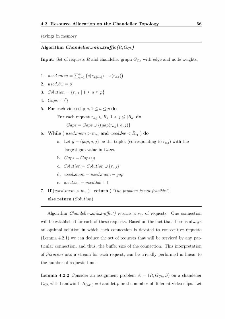
4.2. Resource Allocation on the Chandelier Topology 56
savings in memory.
Algorithm Chandelier min traffic(R, GCh)
Input: Set of requests R and chandelier graph GCh with edge and node weights.
1. used mem =∑p
a=1
(
s(ra,|Ra|) − s(ra,1))
2. used bw = p
3. Solution = {ra,1 | 1 ≤ a ≤ p}
4. Gaps = {}
5. For each video clip a, 1 ≤ a ≤ p do
For each request ra,j ∈ Ra, 1 < j ≤ |Ra| do
Gaps = Gaps ∪ {(gap(ra,j), a, j)}
6. While ( used mem > mv1and used bw < Bv1
) do
a. Let g = (gap, a, j) be the triplet (corresponding to ra,j) with the
largest gap-value in Gaps.
b. Gaps = Gaps\g
c. Solution = Solution ∪ {ra,j}
d. used mem = used mem − gap
e. used bw = used bw + 1
7. If (used mem > mv1) return (“The problem is not feasible”)
else return (Solution)
Algorithm Chandelier min traffic() returns a set of requests. One connection
will be established for each of these requests. Based on the fact that there is always
an optimal solution in which each connection is devoted to consecutive requests
(Lemma 4.2.1) we can deduce the set of requests that will be serviced by any par-
ticular connection, and thus, the buffer size of the connection. This interpretation
of Solution into a stream for each request, can be trivially performed in linear to
the number of requests time.
Lemma 4.2.2 Consider an assignment problem A = (R, GCh, S) on a chandelier
GCh with bandwidth B(s,v1) = i and let p be the number of different video clips. Let

4.2. Resource Allocation on the Chandelier Topology 57
Y be the set of the i − p requests of larger gap. Then, the minimum buffer space
required to service all requests in R is
p∑
a=1
(
s(ra,|Ra|) − s(ra,1))
−∑
r∈Y
gap(r) (4.2)
Proof : By induction on bandwidth i. For the basis, consider the case where
i = p. Then, i − p = 0 and set Y is empty. Thus, the second summation term is
equal to zero. The only way to satisfy all requests is to devote a connection to each
video clip and to set the start time of the connection for clip a to the start time
of request ra,1. Then, the required buffer size for servicing all requests is given by
Equation 4.2.
For the induction step assume that the lemma holds when the bandwidth is
equal to j > p connections. Let r be the request with the (j + 1)-th largest gap. By
introducing a new connection with start time equal to s(r) we can save gap(r) units
of memory and, thus, get a solution of buffer size given by Equation 4.2.
To complete the proof for the induction step, we have to show that there does
not exist a solution which uses less memory. Given that in an optimal solution
the buffers “do not overlap” (alternative statement of Lemma 4.2.1), the optimal
solution can be described in terms of the gaps and the requests which define them.
Given that the sum of j elements (gap-sizes) out of a set is maximized when we add
the j largest elements, it is obvious that we cannot get a solution which uses less
memory than the quantity stated in Equation 4.2. 2
Theorem 4.2.3 Let A = (R, GCh, S) be an allocation problem on the chandelier
network. Then, in O(|R| log |R|) time we can determine whether A is feasible and,
if it is, we can obtain solutions for the minimum total memory and for the minimum
total traffic assignment problems.
Proof : We use Algorithm Chandelier min traffic() to obtain a solution to all
variants of the problem. Algorithm Chandelier min traffic() starts by allocating
one connection to each different video clip. If the required buffer area (denoted
by used memory) is more that the available memory, it introduces one additional
connection. The algorithm stops introducing new connections when the required

4.3. Resource Allocation on the Broom Topology 58
buffer area is sufficient to serve all requests or when the bandwidth out of the
server is exhausted. In the former case, the problem is feasible and, since the
solution returned by the algorithm uses memory equal in size to that suggested by
Lemma 4.2.2, it is a solution to the minimum traffic allocation problem. In the later
case, the problem is obviously not feasible.
Given that for any request r, gap(r) is positive, Lemma 4.2.2 implies that the
solution to the minimum total memory allocation problem uses all available band-
width out of the server. Thus, to produce a solution of minimum total memory it
is enough to modify the condition at step 6 of Algorithm Chandelier min traffic()
to become “used bw < Bv1and Gaps 6= ∅”. We refer to this modified algorithm as
Algorithm Chandelier total memory().
Algorithm Chandelier min traffic() can be easily implemented in O(|R| log |R|)
time by using a priority queue (implemented as a heap) for set Gaps. 2
4.3 Resource Allocation on the Broom Topology
In our study of allocation problems on the broom topology (Fig. 4.1b) we again
assume that each leaf issues one request, that the start times of the requests for the
same video clip are distinct, and that the bandwidth into a leaf is equal to 1.
In trying to identify an optimal solution to a particular assignment problem, it is
useful to know that there exists an optimal solution satisfying some properties. This,
effectively reduces the search space for the optimal solution. The following lemma
describes such a property and is valid for any of the optimization problems defined
in Section 4.1 (minimum total memory, minimum maximum memory per node, and
minimum total traffic). First we need to define the notion of the bandwidth-usage
sequence. Recall that node vl is the hub-node, and that by Into(v) we denote the set
of connections into node v. Given a solution to an allocation problem, the sequence of
l integers (|Into(v1)|, |Into(v2)|, . . . , |Into(vl)|) (implied by the solution) is referred
as the bandwidth-usage sequence. The sequence(
B(S,v1), B(v1,v2), . . . , B(vl−1,vl)
)
is
referred as the bandwidth-capacity sequence. A sequence (x1, . . . , xi, . . . , xn) is said
to be strictly increasing if and only if xi < xi+1, 1 ≤ i < n, and increasing if and

4.3. Resource Allocation on the Broom Topology 59
only if xi ≤ xi+1, 1 ≤ i < n. Strictly decreasing and decreasing sequences are defined
similarly.
Lemma 4.3.1 Consider a feasible allocation problem A = (R, GBr, S) on the broom
network GBr. Then, for each of the minimum total memory, minimum maximum
memory per node, and minimum total traffic versions of allocation problem A, there
exists an optimal solution in which the implied bandwidth-usage sequence is increas-
ing.
Proof : Consider an optimal solution to any version (minimum total memory,
minimum maximum memory per node, or minimum total traffic) of the feasible
allocation problem A. If the bandwidth-usage sequence is increasing, we are done.
If it is not increasing, identify the node v closer to the server which causes the
bandwidth-usage sequence to be non-increasing. Let a′ be the number of connections
into v (out of a possible a) and b′ be the number of connections out of v (out of a
possible b), where a′ > b′. For each of the outgoing connections, we can identify its
parent connection which feeds it with data (possibly through a buffer). In this way,
we can identify up to b′ distinct connections into v which are useful in the sense that
the data they carry is retransmitted. The remaining incoming connections can be
safely dropped, producing an optimal solution in which the number of connections
into node v is equal to the connections out of v. We continue this process until
we cannot identify any node v which causes the bandwidth-usage sequence to be
non-increasing, leaving us with an increasing sequence. The process will obviously
terminate since each node on the broom-stick has at least one connection into it. 2
Remark: Observe that Lemma 4.3.1 also holds for the bandwidth-usage of an
individual video clip. The proof is identical.
Without loss of generality, we can focus only on problems with increasing bandwidth-
capacity sequence. Lemma 4.3.1 established that having greater incoming than
outgoing bandwidth for any node does not help to get a better solution. With
a process identical to that described in the proof of Lemma 4.3.1 we can always
obtain an equivalent increasing bandwidth capacity sequence which we can use
(instead of the original non-increasing one given in the definition of the broom

4.3. Resource Allocation on the Broom Topology 60
GBr) to solve the allocation problem. The elements of any decreasing subsequence
can be replaced by the smallest element, and we repeat until no decreasing sub-
sequence exists. For example, the bandwidth-capacity sequence (7, 6, 4, 7, 8, 3, 5)
is equivalent to (3, 3, 3, 3, 3, 3, 5) as it is established by the sequence of transforma-
tions (7, 6, 4, 7, 8, 3, 5) → (4, 4, 4, 7, 8, 3, 5) → (4, 4, 4, 7, 3, 3, 5) → (4, 4, 4, 3, 3, 3, 5) →
(3, 3, 3, 3, 3, 3, 5).
4.3.1 Minimum Total Memory Allocation on G∞Br
We now focus on the minimum total memory allocation problem for the broom
network. We concentrate on the case where there are no memory bounds on the
amount of memory that we can use for buffering at any node of the broom. To em-
phasize this assumption, we denote the broom network by G∞Br. Let A = (R, G∞
Br, S)
be the allocation problem, and let b be the minimum bandwidth capacity on the
broom-stick of G∞Br. We further assume that the number of different clips in R is
smaller than or equal to b, otherwise, the problem is trivially non-feasible. Given
this assumption and the fact that in G∞Br the amount of available memory per node
is unbounded, allocation problem A is always feasible.
The following lemmas will be used in obtaining an optimal solution to the prob-
lem.
Lemma 4.3.2 Consider a feasible allocation problem A = (R, G∞Br, S) on the broom
network G∞Br. Then, there exists an optimal solution to the minimum total memory
allocation problem A with the property that all incoming connections are immedi-
ately retransmitted, that is, for each connection c1 into an arbitrary node v there
exists a connection c2 out of v with start(c1) = start(c2) and clip(c1) = clip(c2).
Proof : Consider an optimal solution. If all connections are immediately re-
transmitted we are done. Otherwise, we can transform it to an equivalent solution
which satisfies the property. Identify a connection c1 entering node v such that the
connection with the earliest start time out of all connection which get data from
buf(c1), say c2, has start(c2) > start(c1) (Fig. 4.3a). Obviously, clip(c1) = clip(c2).
We can get a solution that uses exactly the same number of connections and at most

4.3. Resource Allocation on the Broom Topology 61
c2
vc1
c2
vc1
a) Delayed retransmission b) Immediate retransmission
Figure 4.3: Incoming connections into a node are immediately retransmitted.
the same total buffer space as the original one by extending the buffer of the parent
connection of c1 to stretch up to time start(c2) and by updating the start time of
connection c1 to be equal to that of c2 (Fig. 4.3b). Repeating the process will yield
an optimal solution in which all connection are immediately retransmitted. 2
Remark: Note that proof fails in the case where the available memory at each
node is bounded. Thus, our focus on network G∞Br instead of GBr.
Remark: The lemma also holds for the problem of minimum total traffic (iden-
tical proof). However, it does not hold for the problem of minimum maximum
memory per node where a setting such as the one shown if Fig. 4.3a is desirable
when an optimal solution spreads a large buffer over a group of consecutive nodes
on the broom-stick.
Lemma 4.3.3 Consider a feasible allocation problem A = (R, GBr, S) and let b
be the minimum bandwidth capacity on the path from the server to the hub on
broom GBr. Then, there exists an optimal solution to the minimum total memory
allocation problem A with exactly b connections out of the server.
Proof : Lemma 4.3.1 implies that there exists an optimal solution for which the
number of connections out of the server is at most b. We show that it is exactly
b. We assume that for the problem at hand the number of requests is greater than
b, otherwise the problem can be trivially solved without using any buffering area.
Assume that we have an optimal solution which uses less that b connections out of
the server. Let v be the node closer to the server that hosts a buffer and let c be
the last connection out of a buffer located at v. The facts that b is the minimum

4.3. Resource Allocation on the Broom Topology 62
q+k
v
c
1 q
1
v1 q
1 q+k’
a) Buffers are located at node v b) The buffers were pushed below node v
Figure 4.4: The number of connections into node v is reduced by pushing buffering area
closer to the hub.
bandwidth capacity and that the number of connections out of the server is smaller
that b imply that we can establish one new connection for each edge at the path
from the server to node v. Let each of these new connections have start time equal
to start(c) and carry the same clip clip(c). By setting the parent connection of c to
be, out of these new connections, the one which enters v, we can reduce the size of
the buffer at v, leading to a solution with less memory than the minimum, a clear
contradiction. 2
Lemma 4.3.4 Consider a feasible allocation problem A = (R, G∞Br, S) on broom
G∞Br. Then, there exists an optimal solution to the minimum total memory allocation
problem A with i) the same number of connections for every edge on the broom-stick,
and ii) all the buffers located at the hub.
Proof : Consider an optimal solution of increasing bandwidth usage with exactly
q connections out of the server which also satisfies the property that each connec-
tion is immediately retransmitted. Such a solution always exists (Lemmata 4.3.1
and 4.3.2). We will show that we can transform it into a solution which uses the
same amount of memory and exactly q connections for every edge on the broom-
stick. Consider the node on the broom-stick which is closer to the server, say v,
with q incoming and q + k, k > 0 outgoing connections. (If such node does not
exist there is nothing to prove.) Then, node v has at least one buffer located to it
(Fig. 4.4).
Consider the leftmost (in time) such buffer and assume that d connections get
their data from it, d ≤ k. By moving the buffer to the node below v (and possibly

4.3. Resource Allocation on the Broom Topology 63
attaching it to a buffer at that node) we do also get a solution which uses the
same amount of memory and has m + k′ connections out of v, where k′ = k − d.
By repeating the procedure, we can get an equivalent solution where the number of
connections out of node v is equal to q, and thus, pushing the node which violates the
property further away from the server. By repeating, we reach the situation where
the only node with more than q connections out of it is the hub node. Observe that
at the end of the transformation all buffering takes place at the hub. 2
We can now state Algorithm Broom total memory() which computes an optimal
solution for the minimum total memory allocation problem A = (R, G∞Br, S) on
broom G∞Br.
Algorithm Broom total memory(R, G∞Br)
Input: Set of requests R and broom graph G∞Br with edge and node weights.
1. Let b be the minimum bandwidth capacity on the broom-stick of G∞Br.
2. Let G∞Ch be the chandelier graph obtained by collapsing the broom-stick of
G∞Br into a single edge of bandwidth capacity B(S,hub) = b.
3. Call Algorithm Chandelier total memory(R, G∞Ch) [defined in proof of Theorem 4.2.3]
4. Expand the solution for G∞Ch to one for G∞
Br.
Step 4 of Algorithm Broom total memory() can be easily implemented. Let the
server node S be also denoted by v0 and recall that the length of the broom-stick is
l. For every connection c in the solution of (R, G∞Ch, S) we simply create the set of
connections {ci : 1 ≤ i ≤ l and orig(ci) = vi−1 and dest(ci) = vi and clip(ci) =
clip(c) and start(ci) = start(c)}.
Theorem 4.3.5 Let A = (R, G∞Br, S) be an allocation problem on the broom net-
work G∞Br. Then, in O(|R| log |R|) time we can obtain a solution for the minimum
total memory allocation problem.
Proof : We employ Algorithm Broom total memory(). The proof of correctness
follows from Lemmas 4.3.3 and 4.3.4.
4.3. Resource Allocation on the Broom Topology 64
Step 3 is the most time consuming step of the algorithm. It needs O(|R| log |R|)
time to terminate (see Theorem 4.2.3). Note that the solution is represented in a
compact form in the sense that it is enough to describe the connections over only
one edge of the broom-stick. If we want to get a solution in the form of one stream
per request we need to describe at most l · b connections on the broom-stick plus an
extra |R| connections into the leaves. Thus, since we assume that b < |R|, we need
O (max(l, log |R|) · |R|) time to compute them. 2
4.3.2 The Minimum Maximum Memory per Node Alloca-
tion problem
The Front-Selection Problem
Consider a 2-level broom (it has exactly one intermediate node between the server
and the hub) where the bandwidth out of the server is B and the bandwidth into
the hub is B + k, k > 0. As shown in Section 4.3.1, there exists an optimal solution
for the minimum total memory problem in which exactly B connections are used
for each edge, each connection is immediately retransmitted, and all buffering area
is located at the hub. In such an optimal solution we can reduce the amount of
memory located at the hub by selecting portions at the front of the buffers which
satisfy at most k requests and moving them to the node above the hub, thus taking
advantage of the extra available bandwidth into the hub. This is illustrated in
Fig. 4.5 where, for the set of requests with starting times in {0, 5, 12, 22, 26, 30}, the
solution computed in Section 4.3.1 which minimizes the total memory uses buffering
area of 20 minutes, all located at the hub (Fig. 4.5a). A solution which uses two
extra connections into the hub “lifts” 9 minutes of memory to the node above the
hub and, as a result, reduces the maximum memory per node to 11 (still at the hub)
and at the same time leaves the total memory used unchanged (Fig. 4.5b).
The solution of Fig. 4.5b has the property that the data over each connection
entering the hub are immediately retransmitted. If we relax this restriction we can
get the solution of Fig. 4.5c where the same amount of buffering area (10 minutes) is
used at both the hub and the node above it. This improved solution is only possible

4.3. Resource Allocation on the Broom Topology 65
Server
5 12 300
0
0
22 26
22
22
Hub
a) All buffers are at the hub
Server
5 12 300
0
0
22
5
26
2622
22
Hub
b) Buffers were pushed above the hub.Immediate retransmission required.
c) Balanced distribution of buffers. Only
Server
5 300
0
0
22 26
22
22
Hub
5
12
10
possible without immediate retransmission.
Figure 4.5: Use of two extra connections into the hub reduces the amount of memory per
node without increasing the total memory.
because we allow the buffering area (of 7 minutes) required to serve the request
which starts at time “12-minutes” to spread over two nodes, 2 minutes of buffering
area at the hub and 5 minutes at the node above it. This balances the total amount
of buffering area between the two nodes and gives a solution to the MMMN problem
for the broom network and the set of requests used in the example of Fig. 4.5.
Observe that the total amount of memory remains unchanged only if we lift to
the node above the hub section(s) from the “front” of the buffer(s). We cannot
move a section from the middle of some buffer since we cannot feed it with data
from the existing connections out of the server (their number is assumed to remain
unchanged).
In the optimal solution to the MMMN problem which is presented in Fig. 4.5c,
only one connection is not immediately retransmitted. As the following lemma
suggests, a feasible allocation problem always has an optimal solution to the MMMN
problem where at most one of the connections between two adjacent nodes is not
immediately retransmitted.
Lemma 4.3.6 Consider a feasible allocation problem A = (R, G, S) and let e =
(v, w) be and edge of network G. Then, there exists a set of connections C(A) which
is a solution to the MMMN allocation problem with the property that at most one
of the connections entering node w over edge e is not immediately retransmitted.

4.3. Resource Allocation on the Broom Topology 66
... ...
... c
d
a
b
...
... ...
...a
b
c
d
...
w
v v
w
a) The smallest segment is at node v b) The smallest segment is at node w
Figure 4.6: One of the two non-immediately transmitted connections can be always
eliminated (proof of Lemma 4.3.6).
Proof : Consider solution C(A). If for every edge e = (v, w) it holds that at
most one connection in solution C(A) enters node w over edge e, we are done. If
this is not the case, let e = (v, w) be an edge for which the property does not hold.
We will show how to get an equivalent solution C ′(A), that is, a solution which
uses at most the same number of connections over edge e and leaves the amount of
buffering area at each of the nodes v and w unchanged.
Consider two arbitrary connections entering node w over edge e = (v, w) which
are not immediately retransmitted. These two connections define four segments of
buffering area, two at node v (segments a and c in Fig. 4.6) and two at node w
(segments b and d in Fig. 4.6). We consider two cases based on the location of the
minimum-size segment.
Case 1: The segment of minimum size is at node v.
Without loss of generality let it be segment a (see Fig. 4.6a) We can get an equivalent
solution with one less non-immediately transmitted connection by:
i) Moving segment a to node w (this also saves one connection), and,
ii) move up to node v from the front of segment d an amount of buffering area equal
to the size of segment a. This is possible since we assumed that segment a is of
minimum size. The resulting (from the above transformations) set of connections
C ′(A) is a solution to problem A which leaves the buffering area at each node
unchanged. In addition, its use of bandwidth is improved since it uses one less
connection over edge e.
Case 2: The segment of minimum size is at node w.

4.3. Resource Allocation on the Broom Topology 67
Without loss of generality let it be segment b (see Fig. 4.6b). We can get an equiv-
alent solution with one less non-immediately transmitted connection by:
i) Moving segment b up to node v, and,
ii) move down to node w from the rear of segment c an amount of buffering area
equal to the size of segment b. This is possible since we assumed that segment a is
of minimum size. The resulting (from the above transformations) set of connections
C ′(A) is also a solution to problem A which leaves the buffering area at each node
unchanged. 2
The above discussion leads to the formulation of the following problem.
Front-selection
Instance: We are given a positive integer k, n sequences of positive
integers Si =(
si1, s
i2, . . . , s
iki
)
, 1 ≤ i ≤ n, 1 ≤ ki ≤ k, and integer λ
such that 0 ≤ λ ≤ max i=1...n
j=1...ki
{sij}.
Question: Is there a way to select at most k elements from the front
of the sequences such that their sum exceeds the sum of the remaining
elements by an even number which is at most 2λ? (Since 0 ≤ λ, the
difference might be equal to zero.)
More formally, is there a sequence of integers X = (x1, x2, . . . , xn) such
that the following hold:
0 ≤ xi ≤ ki for 1 ≤ i ≤ n, (4.3)
n∑
i=1
xi ≤ k, (4.4)
(
n∑
i=1
xi∑
j=1
sij
)
−
n∑
i=1
ki∑
j=xi+1
sij
is even, and (4.5)
0 ≤
(
n∑
i=1
xi∑
j=1
sij
)
−
n∑
i=1
ki∑
j=xi+1
sij
≤ 2λ (4.6)

4.3. Resource Allocation on the Broom Topology 68
Theorem 4.3.7 The front-selection problem is NP-Complete.
Proof : By restriction. We show that the partition problem [61, 62] which is
known to be NP-complete is a special case of the front-selection problem.
In an instance of the partition problem we are given a set A of n positive integers,
and we are asked whether it is possible to partition it into two disjoint sets A1 and
A2 such that the sum of the elements in A1 is equal to the sum of the elements in
A2.
Consider the case of the front-selection problem where each of the n sequences
consists of a single integer, k = n and λ = 0. The set of the n single-element
sequences can be simply treated as a set of n elements (positive integers). Then,
sequence X (of the front-selection problem) defines a partition of the n-element set
into two disjoint sets such that the sum of the elements of the two sets are equal.
Thus, the partition problem is a special case of the front-selection problem. 2
On the computational complexity of the MMMN allocation problem
Our aim is to prove that a natural version the allocation problem of minimizing the
maximum memory per node on a general graph is hard. In doing so, we consider
the following decision problem on a two-level broom:
MMMN-opt-total (Minimum Maximum Memory per Node with respect to the
optimal total memory)
Instance: Set of requests R = {r1, r2, . . . , rd} for the same clip such
that start(ri) < start(ri+1), 1 ≤ i < d, 2-level broom G∞Br2
, and positive
integer MNode.
Question: Does there exists a way to satisfy all requests in R such
that the maximum memory per node is smaller or equal to MNode and
the total memory used is equal to that of an optimal solution to the
minimum total memory problem for request set R on G∞Br2
.
Theorem 4.3.8 The MMMN-opt-total problem is NP-Complete.

4.3. Resource Allocation on the Broom Topology 69
Proof : We reduce the front selection problem to the MMMN-opt-total problem.
Consider an instance IFS = (S1, S2, . . . , Sn, k, λ) of the front selection problem and
let g = 1+max{sij : si
j ∈ Si, 1 ≤ j ≤ ki, 1 ≤ i ≤ n}. Based on IFS, we construct in
polynomial time an instance IMMMN−ot = (R, G∞Br2
, MNode) of the MMMN-opt-total
problem.
Let the set of requests to be R = {rij : 1 ≤ i ≤ n, 0 ≤ j ≤ ki} where
start(rij) =
i−1∑
a=1
(
g +
ki∑
b=1
sab
)
+
j∑
b=1
sib (4.7)
The 2-level broom G∞Br2
consists of the server S, the hub v2, the intermediate
node v1 between the server and the hub, and∑n
i=1 ki + n leaves hanging from the
hub. The bandwidth B(S,v1) out of the server is equal to n, the bandwidth B(v1,v2)
into the hub is equal to n + k, and the bandwidth into each leaf is equal to 1. Each
leaf issues a single request out of those in R.
Finally, we set MNode = total/2 where total is the amount of memory used in
an optimal solution to the minimum total memory allocation problem (R, G∞Br2
, S)
(which can be computed in polynomial time by Algorithm Broom total memory()).
The start times in R can be interpreted as follows: Consider the sequence ob-
tained by attaching integer g to the end of the first n − 1 original sequences, and,
then, by concatenating all the sequences into a new one. The new sequence has∑n
i=1 ki + n − 1 elements and is separated by the element with value g into the
n original sequences. Treat this sequence as the sequence of differences (“gaps” in
the terminology of the presented algorithms) in start times between∑n
i=1 ki + n
consecutive requests, where the starting time of the first request is equal to zero.
Then, the start times are given by Equation 4.7. In the rest of the proof, we say
that requests {rij : 0 ≤ j ≤ ki} correspond to sequence Si, 1 ≤ i ≤ n and vice
versa.
Consider the solution produced by Algorithm Broom total memory() for the min-
imum total memory allocation problem (R, G∞Br2
, S). It uses n connections on every
edge on the broomstick and, after saving space for the n−1 “large” time differences
of size g, it creates n buffers at the hub, where the set of requests which are serviced
by the i-th buffer is {rij : 0 ≤ j ≤ ki} and corresponds to sequence Si, 1 ≤ i ≤ n

4.3. Resource Allocation on the Broom Topology 70
(Lemmas 4.3.3 and 4.3.4). Then, the total memory used is total =∑n
i=1
∑ki
j=1 sij.
Assume that instance IMMMN−ot has a solution. Since the buffer area is measured
in units of memory-minutes (which are indivisible), it follows that total is an even
number, and, exactly total/2 units of memory are placed on each of nodes v2 (the
hub) and v1. Given that the total memory used has to be equal to total, the buffers
at v1 and v2 do not overlap. So, the solution to the instance of IMMMN−ot can be
thought to be derived from the solution given by Algorithm Broom total memory()
by lifting to v1 buffering area which corresponds to at most k requests. For each of
those requests, a new connection was created and at most one of these connections
is not immediately retransmitted (Lemma 4.3.6).
By identifying the connections which feed data to the buffers at the hub, we can
partition each of the n groups of requests into a leftmost and a rightmost part (either
of which can be empty). This gives a partition of the corresponding sequences. In
that partition, the number s (element of some sequence) that corresponds to the
single non-immediately retransmitted connection is included to the leftmost part.
This implies that the difference of the sums of the numbers at each part (leftmost
and rightmost) is even. Moreover, since s ≤ λ, the sum of the elements in the
leftmost part is greater than the sum of the elements in the rightmost part by at
most 2λ. Thus, based on a solution to instance IMMMN−ot of the MMMN-opt-total
problem, we can produce a solution for instance IFS of the front-selection problem.
Conversely, assume that instance IFS of the front-selection problem has a solu-
tion. Then, by placing at node v1 the buffer area that corresponds to the elements
removed from the sequences, and by placing at the hub the buffer area which corre-
sponds to the remaining elements, we get a solution where the buffer area at node
v1 is greater than that of the hub by an even number of at most 2λ units (minutes)
of memory. Thus, by moving at most λ units of memory from node v1 to the hub
we can get a solution where at each node we use exactly total/2 buffering area, as
required by a solution to instance IMMMN−ot. Note that one the streams in the
solution might not be immediately retransmitted. 2
We now define the Minimum Maximum Memory per Node with respect to total
memory usage (MMMN-total) and we state the main result of this section.

4.4. Resource Allocation on a General Tree 71
MMMN-total (Minimum Maximum Memory per Node with respect to total mem-
ory usage)
Instance: An allocation problem A = (R, G, S), and positive integers
MNode and Mtotal.
Question: Does there exist a solution to problem A such that the maxi-
mum memory per node is smaller or equal to MNode and the total memory
used is smaller or equal to Mtotal.
Theorem 4.3.9 The MMMN-total problem is NP-Complete.
Proof : Simply observe that the MMMN-opt-total problem which was shown to
be NP-Complete in Theorem 4.3.8 is a special case of the MMMN-total problem
where the graph G is restricted to a two-level broom G∞br2
, the set of requests is
restricted to the same clip, and Mtotal is set to be equal to the optimal solution of
the minimum total memory problem for the same set of requests on broom G∞br2
. 2
4.4 Resource Allocation on a General Tree
In this section we present a heuristic for computing a solution to an allocation
problem on a general tree where the root of the tree acts as the server and all
requests are issued at the leaves. Without loss of generality, we assume that the
root has only one child. If this is not the case, we can solve the problem on each tree
obtained by deleting all but one subtree of the root and, at the end, by combining
the solutions to these subproblems. We assume that there are no bounds on the
amount of memory that can be used for buffering at any node of the tree and, to
emphasize this, we denote the tree by T∞.
Heuristic Tree allocation(R, T∞)
Input: Tree T∞ with edge weights only, and set of requests R (all issued at the leaves of T∞)
1. Solution = {}
2. while (T∞ contain at least one internal node different than the root) do

4.4. Resource Allocation on a General Tree 72
a. Let v be an internal node that has only leaves as its children.
Denote by T∞v the subtree rooted at v.
Let Rv ⊆ R be the set of requests issued by the children of v.
b. Let chandelier Ch∞v be formed by the parent p(v) of v (root), v itself (hub), and
and the children of v. The bandwidth into v is equal to its original value B(p(v),v).
c. Call Algorithm Chandelier total memory(). Let the solution place b
buffers at v and let Cv = {c1, c2, . . . , cb} be the set of connection into v
which feed these buffers with data and Cleaves be the set of connections
into the children of v.
d. Solution = Solution ∪ Cleaves
e. Update T∞ by replacing T∞v with b nodes v1, v2, . . . , vb, each with one unit
of bandwidth into it.
f. If (T∞ contains at least one internal node different than the root)
then Update R by:
i) removing the requests issued by the children of v and then,
ii) inserting b new requests {ri : 1 ≤ i ≤ b} (each one
corresponding to a request in Cv) where s(ri) = start(ci),
clip(ri) = clip(ci), and i(ri) = vi, 1 ≤ i ≤ b.
else Solution = Solution ∪ Cv
3. return Solution
The solution returned by Heuristic Tree allocation() consists of a set of connections
which carry all the necessary information we need in order to deduce how to set up
the buffers at the nodes of T∞ so we can satisfy all requests in R.
Unfortunately, we were not able to provide any non-trivial bound on the quality
of the heuristic. We were only able to demonstrate (by constructing simple instances
of the allocation problem) that, even for the broom network, it does not compute
the optimal solution to either the minimum total memory or minimum maximum
memory per node problem.

Chapter 5
Online Algorithmic Support for
Delayed Multicast
In Chapter 3, the Delayed-Multicast transmission technique was proposed to support
Video-on-Demand. It introduces buffers within the network to bridge the temporal
delays between similar requests thus minimizing the aggregate bandwidth and server
load. Chapter 4 derived an optimal offline algorithm, Chandelier Algorithm, for
simple three-level tree topology, which given a set of request times, allocates buffer
space so that the total transmission cost from the server to the intermediate node
is minimal and the amount of buffer space allocated is also minimal.
This chapter introduces an improved online algorithm for resource allocation
with Delayed-Multicast by utilizing prior knowledge of each clip’s popularity. The
algorithm is intended to be simple so as to allow for deployment at multiple levels
in a distribution network.
5.1 Online Heuristics
We first examine the algorithm for the online three-level topology since that forms
the basis of the distributed algorithm. The idea behind the handling of online
requests is as follows. When the node receives the first request ri for a particular
clip, it creates a buffer of size si and forwards that request to the server. For
subsequent requests ri+1 of the same clip, if t(ri+1) ≤ t(ri) + si then clearly, it can
73

5.1. Online Heuristics 74
be serviced from that buffer otherwise it needs a new buffer with a corresponding
stream from the server. The question is what should si be to maximize the number
of requests that can be served from it given the limit of available buffer space S at
that node.
In an online scenario, while the exact request times are not known a priori, one
can assume the arrival times of video requests to follow a Poisson distribution with an
average number of requests λ over a period P . Furthermore, in the case of a video
library rental, certain videos such as new releases are more popular than others.
If the videos are ordered according to their popularity, the probability, pi, that a
request selects a particular video, i, i = 1, 2, ..., N , follows the Zipf distribution [63]
given by:
pi = 1/izKN where KN =N∑
i=1
1/iz (5.1)
The skew factor, z, that has been found to closely match the selection probability
at a video library rental is 0.271 [21].
It can be seen that as more buffer space is allocated to a video, the aggregate
bandwidth saving for that video also increases because there is a greater likelihood
that a request will be serviced from the buffer space rather than from the server.
Thus if more buffer space is allocated to more frequent videos then more requests can
be served from the buffer space, resulting in greater bandwidth saving. Similarly,
allocating more buffer space to longer videos also yield more saving.
Based on these observations, for each clip i with its respective length Li, we
partition the total space available S into Si, Sj, ..., SN where Si is the buffer space
reserved for video i and is given by Si = piLiS/∑N
j=1 pjLj . The partition of the
buffer space has the advantage that infrequent requests do not take up excessive
buffer space and starving more frequent requests. Compare this with the Chandelier
algorithm, we see that no differentiation is made there in terms of a clip’s popularity.
As a result, infrequent requests can lead to no solution since they will exhaust the
available buffer space.
However, if we apply the partition technique, and run the Chandelier algorithm
separately for each clip, i, with the available buffer space set to the corresponding Si,

5.1. Online Heuristics 75
the resultant buffer allocation is the optimal for that clip albeit only for the offline
cases. In other words, this is equivalent to running the Chandelier algorithm on each
group of requests where the input is |Z| = 1 and S = Si for each clip i, 1 ≤ i ≤ N .
We refer to this algorithm as the Partitioned Chandelier algorithm.
The aim of the online algorithm, “Online DMP” algorithm, is to try and achieve
the same result as the Partitioned Chandelier Algorithm over the same time period
P . The algorithm is run every time a new request arrives, at the granularity of 1
minute. For ease of understanding the algorithms that we will be presenting, we
define a few new notations below
Notations used in Online DMP Algorithm
Total buffer space allocated to sessions
Sallocatedi buffering clip i
rlast The previous request for clip i
The request at the start of the buffer
rstart serving rlast.
size(rk) Size of buffer with request rk at the start.
The basic idea of the algorithm can be explained as follows. When the first
request arrives for a video, i, it creates a new session whose buffer size is the whole
buffer space allocated to video i, namely Si. For subsequent requests, it simply
checks whether or not to serve the request from the buffer or create a new session.
The decision is based on a threshold T . If the inter-arrival time between the new
request, r, and the last request for the same clip, rlast, is less than the threshold,
T , the request can be serviced from the existing buffer if one exist. Otherwise the
buffer of the previous request is re-sized to stop at the last request, rlast, while the
new request is assigned to a new session whose buffer size is equal to all the free
buffer space available to clip i at that point in time. This operation is illustrated
in Figure 5.1. It is important to note that our scheme is unlike other techniques
which fix the sizes of the buffers at the time they are created. Instead, we try to
allocate as large a buffer as possible and then later “trim” the buffer from the back,
depending on the inter-arrival threshold T . In a later section we will analyze how
to determine the threshold value T .
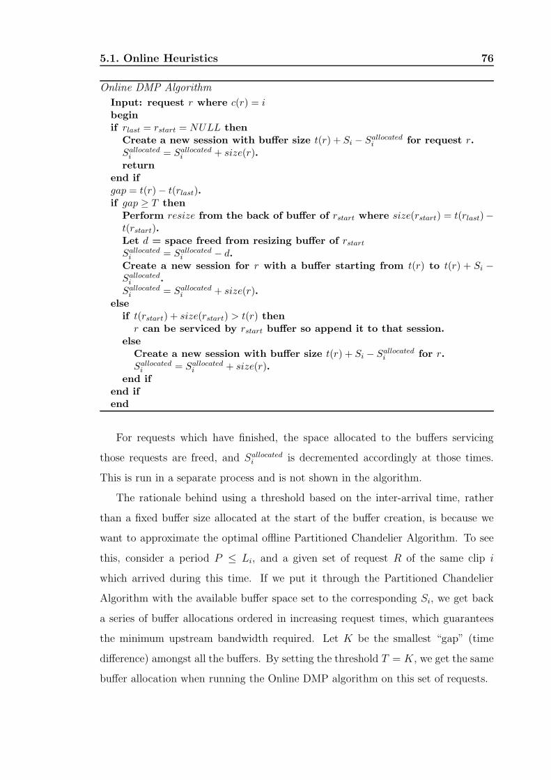
5.1. Online Heuristics 76
Online DMP Algorithm
Input: request r where c(r) = i
beginif rlast = rstart = NULL then
Create a new session with buffer size t(r) + Si − Sallocatedi for request r.
Sallocatedi = Sallocated
i + size(r).return
end ifgap = t(r) − t(rlast).if gap ≥ T then
Perform resize from the back of buffer of rstart where size(rstart) = t(rlast)−t(rstart).Let d = space freed from resizing buffer of rstart
Sallocatedi = Sallocated
i − d.Create a new session for r with a buffer starting from t(r) to t(r) + Si −Sallocated
i .Sallocated
i = Sallocatedi + size(r).
elseif t(rstart) + size(rstart) > t(r) then
r can be serviced by rstart buffer so append it to that session.else
Create a new session with buffer size t(r) + Si − Sallocatedi for r.
Sallocatedi = Sallocated
i + size(r).end if
end ifend
For requests which have finished, the space allocated to the buffers servicing
those requests are freed, and Sallocatedi is decremented accordingly at those times.
This is run in a separate process and is not shown in the algorithm.
The rationale behind using a threshold based on the inter-arrival time, rather
than a fixed buffer size allocated at the start of the buffer creation, is because we
want to approximate the optimal offline Partitioned Chandelier Algorithm. To see
this, consider a period P ≤ Li, and a given set of request R of the same clip i
which arrived during this time. If we put it through the Partitioned Chandelier
Algorithm with the available buffer space set to the corresponding Si, we get back
a series of buffer allocations ordered in increasing request times, which guarantees
the minimum upstream bandwidth required. Let K be the smallest “gap” (time
difference) amongst all the buffers. By setting the threshold T = K, we get the same
buffer allocation when running the Online DMP algorithm on this set of requests.

5.1. Online Heuristics 77
startt(r )
Buffer of r start
Buffer of r startBuffer of r startt(r )
kt(r )
last t(r)
T
gap
Timeline
Before
After
New buffer for r
Filled portion
d
Figure 5.1: The “resize” operation when a new request r arrives at time t(r) and whose
inter-arrival time gap > T .
5.1.1 Determining Threshold Value, T
The performance of the Online DMP algorithm is based on correctly choosing the
threshold value Ti for each clip i. Too large a value will cause initial requests to
greedily consume all the available buffer space, preventing subsequent ones to form
buffers even though they may be closer together. On the other hand, if T is too
small with respect to the average inter-arrival time, requests will also not be able to
form buffers. In the following section, we present an approximation algorithm for
the threshold Ti. We assume request arrival times follow a Poisson process with λi
average rate of arrivals per minute.
A boundary case is when Si << 1/λi, Online DMP algorithm will have no effect
here because there is insufficient buffer space to bridge the temporal differences
between rare requests. In this situation, it is better not to perform DMP on clip i
and instead reserve space for more popular clips. This is done using the “eighty-
twenty” rule, i.e. we only perform DMP on the most popular 20% of the clips.
To approximate Ti, we consider a period equivalent to the length of the movie Li.
The expected number of arrivals during this period is λiLi. Assuming all the buffer
space Si is to be used during this period, then the average buffer space allocated
per request is given by Si/λiLi.

5.1. Online Heuristics 78
Let ni be the number of actual requests for clip i which has arrived up to this
point, t, 0 < t ≤ Li. We denote Sfixedi to be the sum of all the buffer space allocated
to clip i excluding the buffer space from t(rlast) to the end of that buffer. To ensure
that Ti is not set to large so as to “hog” the buffer space, we use the condition below
to determine whether or not the current request r should be part the existing buffer
or start a new one:
if Si/λiLi ≤ (Sfixedi + gap)/n then
Create a new buffer
else
Continue as part of the existing buffer
end if
Or to put it another way, the threshold Ti is given by
Ti = min{(Sin/λiLi) − Sfixedi , t(rstart) + size(rstart) − t(rlast)} (5.2)
Thus the threshold value Ti is not fixed but varies at each processing of new
requests.
5.1.2 Applying Online DMP Algorithm on General Tree
Network
The job of each node in the overlay tree is to receive incoming requests from reg-
istered children nodes immediately below it. To service them, each node runs the
Online DMP algorithm based on the requests it receives from the children nodes. If
in order to satisfy the requests, new sessions are needed, it will forward a request for
the required clip to its parent. The same process occurs again in the parent node.
Thus, an initial request for a clip will be forwarded hop by hop in the overlay tree
with a new session created at each point.
It is important to note that for the Online DMP algorithm, it does not require
complex signalling between the parent and the child node. All that is needed is the
initial request from the child to the parent node. Furthermore, the only changes
that can occur to the buffer is done through the resize operation which occurs from
the back of the buffer. As a result, the request times of the streams coming from the
5.1. Online Heuristics 79
parent node to feed into the front of that buffer does not need to change (assuming
users do not quit midway through the video). The local nature of changes makes
it ideal for employing Online DMP algorithm at multiple levels in the distribution
tree. If they were allowed to change frequently, any optimization done at higher
levels would no longer be optimal. In addition, the new algorithm does not require
complex signalling between the parent and child node. All that is needed is the
initial request from the child to the parent.
Another advantage arising from the distributed nature of the Online DMP algo-
rithm is the fact that each node can individually keep track of their requests from
their children and adjust the popularity of different videos on the fly to reflect their
true popularity. This is especially important for higher nodes where rare requests
tends to become more popular as they accumulate further up the distribution tree.
5.1.3 Simulation Results
In this section we examine the effectiveness of Online DMP through simulations.
We assume that there is no defection - users do not quit midway through viewing
the video clips. We also assume that there is no blocking, i.e. all requests can be
satisfied. The performance metric we are interested in is the average transmission
cost from the server to the DMP-enabled per client, measured in terms of clip
minutes transmitted, normalized over the clip’s length Li.
As mentioned earlier, we assume the arrival times of video requests to follow
a Poisson distribution with an average number of requests, λ, over a period P.
For each request, we simulated the video that would be selected following the Zipf
distribution (Equation 5.1). As a result, the inter-arrival time for all requests do
not depend on the clip’s popularity, but the inter-arrival time for each clip i, does
depend on that clip’s popularity. This gives rise to our parameter λi which we use
in our simulations.
In general, the simulation results presented here and in subsequent chapters are
all done by averaging the results of multiple runs, within a 95% confidence level.
In the first case, we wish to see how the effects of using a fixed threshold value
for different rate of arrivals. The buffer space is fixed at 30min, the length of the

5.1. Online Heuristics 80
video is 120 min, and the experiment runs for 2 hours. The results are illustrated
in Figure 5.2. For small λi = 0.003, it can be seen that running “Online DMP”
algorithm has no benefit. This corresponds to the case S << 1/λi. For other λi
values the optimal fixed threshold closely matches the value of 1/λi + ǫ. This is
to be expected since the average inter-arrival time is given by 1/λi. The curves all
show that beyond the optimal threshold, at a certain point the bandwidth saving
is just a straight line. This is equivalent to selecting too large a threshold and as a
result, buffer space is all used up at the start of the run. All threshold values beyond
this point will clearly give the same result, since there is no buffer space left for any
buffering; hence the straight lines.
0.3
0.4
0.5
0.6
0.7
0.8
0.9
1
0 5 10 15 20 25 30
Nor
mal
ized
Ave
rage
Tra
nsm
issi
on C
ost P
er C
lient
Threshold, T
λ = 0.03λ = 0.1λ = 0.3λ = 0.5λ = 0.7
λ = 1
Figure 5.2: Effects of arrival rate, λ, and fixed threshold, T , on transmission cost. Buffer
space is fixed at 30 min.
Next we compare “Online DMP” algorithm against three base cases: no caching
or batching, batching (at 1 minute interval), and batching with traditional caching.
Note that our algorithm can be described as batching with “Online DMP” since the
algorithm is run at the time granularity of 1 minute. We compare these schemes in

5.1. Online Heuristics 81
a three level topology, since that is the basis of the distributed algorithm.
In the first case, the average transmission cost C from the parent node over a
period Li is simply λiL2i . In the second case, we have:
C =
λiL2i if λ < 1
L2i if λ ≥ 1
(5.3)
The result arises from the fact that when λ ≥ 1, batching takes effect and so
there is an upper limit on the number of streams required from the server. For
batching with traditional caching of size Si (i.e. a prefix of the clip of size Si is
always kept at the intermediate node) the cost over the duration Li minutes is
C =
Li if Li − Si = 0
λiLi(Li − Si) + Si if λ < 1 and Li − Si > 0
Li(Li − Si) + Si if λ ≥ 1 and Li − Si > 0
(5.4)
since for every stream coming from the server, only Li − Si portion needs to be
streamed plus the initial cost of sending the cache portion, Si. The comparisons of
these schemes with Online DMP are presented in Figures 5.3 to 5.7. The threshold
values, Ti, used were dynamically determined using the approximation technique
mentioned earlier.
The results for Batching & Caching are shown as straight linear line because
the same requests set, generated at the start of the simulation, is reused for each
Si value. As a result, there is a linear relationship as more buffer space becomes
available.
Figures 5.3 to 5.7 shows that for all λi and Si, the savings achieved by Online
DMP algorithm is greater than the traditional caching with batching. The only
exception is when Si ≈ Li, where it is obvious that the better solution is the caching
of the entire clip. Furthermore, when comparing the savings at the buffer space of
30 min against that for Figure 5.2, we see that our variable approximation of Ti
achieves almost the same results as the optimal fixed threshold for the various λi.
Another point of interest is the performance of our buffer space partitioning
scheme. As mentioned earlier we adopt the “eighty-twenty” rule do decide which
clips to perform DMP on. In addition we then partition based on the popularity of

5.1. Online Heuristics 82
0
0.2
0.4
0.6
0.8
1
0 20 40 60 80 100 120
Nor
mal
ized
Ave
rage
Tra
nsm
issi
on C
ost P
er C
lient
Buffer Space, S (in minutes)
a) λ = 0.1
Online DMPNo Batching
BatchingBatching & Caching
Figure 5.3: Bandwidth savings for Online DMP, λ = 0.1
0
0.2
0.4
0.6
0.8
1
0 20 40 60 80 100 120
Nor
mal
ized
Ave
rage
Tra
nsm
issi
on C
ost P
er C
lient
Buffer Space, S (in minutes)
b) λ = 0.3
Online DMPNo Batching
BatchingBatching & Caching
Figure 5.4: Bandwidth savings for Online DMP, λ = 0.3

5.1. Online Heuristics 83
0
0.2
0.4
0.6
0.8
1
0 20 40 60 80 100 120
Nor
mal
ized
Ave
rage
Tra
nsm
issi
on C
ost P
er C
lient
Buffer Space, S (in minutes)
c) λ = 0.5
Online DMPNo Batching
BatchingBatching & Caching
Figure 5.5: Bandwidth savings for Online DMP, λ = 0.5
0
0.2
0.4
0.6
0.8
1
0 20 40 60 80 100 120
Nor
mal
ized
Ave
rage
Tra
nsm
issi
on C
ost P
er C
lient
Buffer Space, S (in minutes)
d) λ = 0.7
Online DMPNo Batching
BatchingBatching & Caching
Figure 5.6: Bandwidth savings for Online DMP, λ = 0.7

5.2. Summary 84
0
0.2
0.4
0.6
0.8
1
0 20 40 60 80 100 120
Nor
mal
ized
Ave
rage
Tra
nsm
issi
on C
ost P
er C
lient
Buffer Space, S (in minutes)
e) λ = 1
Online DMPNo Batching
BatchingBatching & Caching
Figure 5.7: Bandwidth savings for Online DMP, λ = 1
the clip (i.e. using the Zipf distribution). In the simulation, we have a library of 50
different clips of different lengths, uniformly distributed between 100 min and 120
min. The Zipf skew factor of 0.271 is used.
Figure 5.8 shows the results of our partitioning scheme against the naive equal
partition scheme (where the available buffer space is equally shared amongst all the
clips), and one which simply uses the “eighty-twenty” rule (i.e. the buffer space is
equally shared amongst the 20% most popular clips). The effects of the “eighty-
twenty” rule clearly has the most effect with a large amount of savings achieved.
Our scheme with further partitions the space for each popular clip based on its
popularity ranking achieves slightly more bandwidth savings.
5.2 Summary
In this chapter we introduced a new online algorithm, “Online DMP”. Our algo-
rithm relies on a threshold value for the inter-arrival time to determine whether or
not to start a new stream or service the new request from an existing prefix cache.
The simplicity of the algorithm enables it to be deployed at multiple levels in the
distribution tree, thus further improving bandwidth utilization. To further improve

5.2. Summary 85
60
65
70
75
80
85
90
95
100
0.02 0.03 0.04 0.05 0.06 0.07 0.08 0.09 0.1 0.11
Ave
rage
Tra
nsm
issi
on C
ost P
er C
lient
Buffer Space/Lengths of All Movies
a) λ = 5.00
80-20 Rule and Zipf Proportional80-20 Rule
Equal Parition
60
65
70
75
80
85
90
95
0.02 0.03 0.04 0.05 0.06 0.07 0.08 0.09 0.1 0.11
Ave
rage
Tra
nsm
issi
on C
ost P
er C
lient
Buffer Space/Lengths of All Movies
b) λ = 10.00
80-20 Rule and Zipf Proportional80-20 Rule
Equal Parition
Figure 5.8: Comparison of different buffer allocation schemes.
bandwidth savings, we utilize a buffer space partitioning scheme that exploits dif-
ferent clip’s popularity to optimize buffer allocation which in turns leads to better
bandwidth savings.

Chapter 6
Cost-based Optimization
6.1 Motivation and Problem Statement
Previous works on providing video-on-demand have concentrated on minimizing
upstream aggregate bandwidth at the expense of buffer space. Hua et al. [22, 23]
introduces a technique termed “patching” which utilizes buffer space at the client’s
set-top box (STB), or an intermediary buffer device to minimize network bandwidth.
With patching, initial requests are serviced using a regular multicast. Subsequent
requests for the same clip are serviced immediately with a stream from the server
known as a “patching” stream. However, rather than subscribing only to its patching
channel, the later client also subscribes to the nearest earlier regular multicast, using
the patching stream for immediate display while buffering the data from the regular
multicast on disk. Once the buffered data is sufficient to bridge the temporal skew
between the two multicasts, the display data is fetched from the buffer and the
patching stream is terminated. Variations to the patching scheme was introduced
in [25] to reduce the required last mile bandwidth requirement to below twice the
bit rate of the video clip, and in [26] to address the issue of packet loss recovery.
Recent works [64–66] introduce the concept of proxy caching. A straight forward
application of proxy caching is to permanently cache portions of popular clips. The
advantage of this is that it can reduce latency, and mask network jitters, in addition
to reducing resource requirement. More advanced forms of proxy caching makes
use of batching and patching at the proxy to further reduce network bandwidth
86

6.2. Cost Optimization Algorithm 87
requirement.
However, minimizing bandwidth at the expense of buffer space does not always
reflect the true cost effectiveness of the system. Instead, we see each buffering
device, like network bandwidth, can be a commodity that is offered by a third party
who charges for its use based on the amount of storage required as well as for the
duration.
A common way of providing costing for storage is through amortization. For
example, let’s assume the overall cost for a machine supporting a storage system
capable of storing M MB is $K, and that the clips are constant bit rate videos, b
MB/sec. The storage cost for one minute of video, S, is given by K ∗ b ∗ 60/M in
$/min. Furthermore, we assume that the storage system is to be amortized over the
space of one year and that it is to be used on average h hours per day. Consequently,
the amortized cost S, given by S/(365 ∗ h ∗ 60) in units $/min.min, represents the
cost of storing one minute of video for the duration of one minute. Note that the
amortization cost may include an adjustment to take into account other costs such
as maintenance and electricity. Figure 6.1 illustrates the different value of S for
various system costs K ranging from $1000 to $10000. Note that the buffer space
we refer to is memory space rather than disk buffer; hence the high system cost.
This is due to the fact that disk, despite its large capacity, does not have sufficient
I/O bandwidth and access time to support many concurrent video streams.
Our aim is to investigate the economic aspect of the problem, i.e. how best to
minimize the total cost in monetary terms for a given VoD system. While bandwidth
versus storage cost plays a crucial role in the overall cost of a system, other variables
such as the popularity of different videos, and their lengths also play a crucial role.
6.2 Cost Optimization Algorithm
In this section, we will first describe an offline (requests are known a priori) algo-
rithm which minimizes the overall system cost. However, because the offline case
is limited to when users are booking their viewing times in advance, we will then
show how the offline algorithm can be transformed to an online one that has wider

6.2. Cost Optimization Algorithm 88
0
0.0005
0.001
0.0015
0.002
0.0025
1000 10000
Am
ortiz
ed S
tora
ge C
ost,
$/m
in.m
in
System Cost K, $
M = 1GB, b = 0.65MB/sec, h = 8 hours
Figure 6.1: Graph showing the amortized cost for various system cost M with fixed
buffer (1GB), constant bit rate video (5Mb/sec) and average usage of 8 hours per
day.
applicability. Some notations which we will be using are listed below.
ri,x the ith request time for video x
Rx ordered set of request times for video x
gap(ri,x, rj,x) the time difference between requests =
rj,x − ri,x
bx CBR bit rate of video x in MB/sec
Lx Length of video x in minutes
B bandwidth cost per minute of CBR video
S buffer cost per minute of CBR video
h average operating hours per day
S amortized cost, S/(365 ∗ h ∗ 60)
γx bandwidth versus storage cost ratio =
B/S
In our algorithm, we partition requests into individual sets Rx according to the

6.2. Cost Optimization Algorithm 89
respective video clip x being requested and apply it on each of these set of requests.
For that reason, we will drop the subscript x when referring to a request ri,x in
our description of the algorithm. The algorithm also makes use of the following
operations:
a) allocate(ri) denotes that request ri is part of an allocated buffer. Initially all
requests are unallocated.
b) cluster(ri) = {ri, ..., rn} where gap(rj, rj+1) < T, i ≤ j < n, and rj is unallocated,
∀i ≤ j ≤ n. In other words, for every request in this cluster starting from ri, the
time difference between it and the previous request is less than a given threshold T .
This is illustrated in Figure 6.2.
c)|cluster(ri)| denotes the number of requests in cluster(ri).
d) buffer(ri) denotes that a buffer of size rn − ri, where rn is the last request in
cluster(ri), is allocated. A new stream feeding that buffer at time ri is also initiated.
r1
gap <Tgap <T gap <T
r r r2 3 4 r5
gap > T
T
Figure 6.2: Illustration of the cluster operation where cluster(r1) = {r1, r2, r3, r4},
cluster(r2) = {r2, r3, r4}, cluster(r3) = {r3, r4}, cluster(r4) = {r4}, and
cluster(r5) = {r5}.
Before the algorithm starts, it is necessary to define a threshold T which repre-
sents the point at which a new buffer should be created. An obvious value for T is
the ratio γ because this represents the point at which it becomes more expensive to
buffer the request rather than stream it directly.
The basic idea behind the algorithm is to first work out the cluster for each
request where initially all requests are marked as not allocated. If there is a cluster
whose size exceeds the length of the movie, then clearly it’s better to buffer the
entire clip, otherwise the algorithm iterates until all requests have been marked as

6.2. Cost Optimization Algorithm 90
Algorithm 1 Clustering Algorithm
for all ri such that riǫR do
-determine cluster(ri)
end for
if there exist riǫR such that |cluster(ri)| ≥ L then
-buffer the entire clip
else
while there exist unallocated requests do
-select ri such that (allocate(ri) = false) and |cluster(ri)| is the next largest.
-buffer(ri)
for all rj such that rj ǫ cluster(ri) do
-allocate(rj)
end for
end while
end if
allocated. At each step, it selects a request, ri, which has not been allocated and with
the largest cluster size, |cluster(ri)|. It initiates a new stream and creates a buffer
for that request whose size is equivalent to the time difference between ri and the
last request in cluster(ri). All requests in the cluster beginning with ri are marked
as allocated since they will be serviced from that buffer. Using the inputs seen in
Figure 6.2, the results from the clustering algorithm will be two streams from above
for two buffers: buffer(ri) of length r4 − r1 and buffer(r5) of length 0.
6.2.1 Online Clustering Algorithm
To change the algorithm to the online version, we need to redefine the operation
buffer(ri). This is because we do not have a priori knowledge to perform the cluster
operation, and thus we do not know what the final sizes of the buffers to allocate
are. As a result, rather than creating a buffer of fixed size, buffer(ri) simply creates
a buffer starting from ri and allows it to grow dynamically with subsequent requests
being served from this buffer. This is referred to as a dynamic buffer. The buffer

6.2. Cost Optimization Algorithm 91
stops being dynamic, i.e. stops growing, when:
a) the size of the buffer is > L. In this case, we are caching the entire clip.
b) t− rn > T where t denotes the current time and rn is the most recent request. In
this case, the buffer space between rn and t is freed and the buffer now operates as a
circular buffer starting from ri and ending at rn. When request rn+1 arrives, a new
dynamic buffer is created and the process is repeated. Note that gap(rn, rn+1) > T .
Algorithm 2 Online Clustering Algorithm
for each t minutes do
if there is a dynamic buffer and its current length = L then
-mark it non-dynamic and serve all requests from this buffer. Free all other
buffers of the same clip.
end if
if a new request ri arrived then
if there is a dynamic buffer, buffer(rk) then
-append ri to the dynamic buffer, buffer(rk)
else
-create a new dynamic buffer, i.e. buffer(ri)
end if
else
if there is a dynamic buffer, buffer(rk) then
-let rn be the most recent request.
if t − rn > T then
-free buffer space between t − rn
-buffer(rk) is now a circular buffer of size rn − rk. Mark buffer(rk) as
non-dynamic.
end if
end if
end if
end for
It should be noted that the resultant buffer allocations for the online and offline
algorithm are the same. The only difference is that the online algorithm will always

6.3. Simulation Results 92
incur a slightly higher storage cost since it allows the buffer space between allocated
buffers to be utilized up till the threshold T before it is freed. This is unavoidable
because we do not know beforehand when the next request will arrive and therefore
must let each buffer grows until the threshold T is reached.
Similar to the online heuristics presented in Chapter 5 which can be applied on
the general tree (see Section 5.1.2), our Online Clustering Algorithm can also be
applied on the general tree in the same manner. The only difference here is that we
take into consideration the buffer space by factoring it into the monetary cost.
It is clear that the performance of the algorithms (both online and offline) are
dependent on the threshold value T . For our algorithms, we have chosen T to be γ,
which represents the tradeoff between bandwidth and buffer space. At one extreme,
if γ < 1, this means that it is more expensive to buffer 1 minute of data compare with
streaming one minute worth of data, hence it is always better to service requests
as they arrive with a new stream. If γ is much larger, then this indicates that it is
much cheaper to have large buffers and fewer streams.
The value of T and its effect on the overall system cost is the focus of our
simulation studies. We will also examine the effects of arrival rates and clip length
to determine when it is more cost-effective to use our algorithms. We compare our
algorithms against the default techniques of buffering the entire clip and no buffering
(i.e. a new stream for each request).
6.3 Simulation Results
Before discussing our simulation results, it is necessary to examine what are the
reasonable values for amortized buffer cost S and bandwidth cost B that can be
used in our simulations. A typical system cost, K, ranges from $3000 to $5000 once
maintenance and electricity costs are taken into account in addition to the once off
set up costs of acquiring the system. From Figure 6.1, this implies that a reasonable
amortized buffer cost is $0.001/min.min.
In terms of bandwidth cost, this represents the cost to transmit the video clip
from the server to the buffering device. Since buffering devices are placed at the

6.3. Simulation Results 93
headends or DSLAMs in the distribution network, this bandwidth cost excludes the
cost to stream the clip from the buffering device to the users. A typical value for
the the cost of this “core bandwidth” ranges from $0.1 to $1.0 to transmit $100
min of high quality (5Mb/sec); the value being dependent on the technology being
employed in the core network which differs from operators to operators. However,
we believe a reasonable value for B is $0.006/min (i.e. it costs around $0.60 to
deliver a 100 min video to the headend).
Our simulations also assume that requests follow a Poisson distribution with an
average number of requests λ over the simulation period. The same assumption that
has been made in previous works [64–66].
6.3.1 Effects of threshold value T
As stated earlier, the threshold value T is crucial to the performance of the Cluster
Algorithm and Online Cluster Algorithm. Figure 6.3 shows the results of various
T values for the Cluster Algorithm and the Online Cluster Algorithm. The movie
length, L, is fixed at 100 min and the arrival rate is 0.3 req/min. The duration of
the simulation is over a 400 min period. The rationale for the simulation lenght of
400 min is because we want to select a simulation time that would be a multiple
of the length of the selected movie (set at 100 min). This allows the simulation to
take into account the effects of freed up resources as early users finished watching
their clips. A multiple of 4 times the length of the movie was considered to be a
reasonable length of time for the simulation in order for the above factor to be taken
into account. We compare our results with a system which employs no buffering
and one which caches the entire clip.
Even for small value of T (2 min), there is still significant saving over the naive
no buffering system which exhibits the highest cost. However when compared to the
complete buffering system, our algorithms using small T value show slightly higher
cost. The reason is because T is not sufficiently large enough to bridge the temporal
differences between most requests which has an average inter-arrival time of 1/λ
or 3 min. At the other extreme, T = 10min, we see that both algorithms default
to buffering the entire clip. The reason for this is because when T is very large,
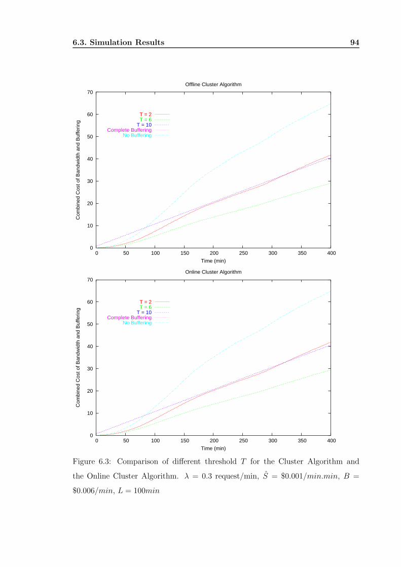
6.3. Simulation Results 94
0
10
20
30
40
50
60
70
0 50 100 150 200 250 300 350 400
Com
bine
d C
ost o
f Ban
dwid
th a
nd B
uffe
ring
Time (min)
Offline Cluster Algorithm
T = 2T = 6
T = 10Complete Buffering
No Buffering
0
10
20
30
40
50
60
70
0 50 100 150 200 250 300 350 400
Com
bine
d C
ost o
f Ban
dwid
th a
nd B
uffe
ring
Time (min)
Online Cluster Algorithm
T = 2T = 6
T = 10Complete Buffering
No Buffering
Figure 6.3: Comparison of different threshold T for the Cluster Algorithm and
the Online Cluster Algorithm. λ = 0.3 request/min, S = $0.001/min.min, B =
$0.006/min, L = 100min

6.3. Simulation Results 95
requests are simply “chained” together in the same buffer resulting in a buffer as
large as the clip length. Hence the cost here is the same as the complete buffering
case.
The results also confirm our belief that T should be set to be the ratio γ which
represents the trade-off point above which it is more beneficial to start a new stream
rather than serve the request from a buffer. From the results, it can be seen that
for T = 6 = γ, the resultant cost is much lower than any other schemes.
Comparing the performance of the online and offline algorithm, we see that the
results are almost identical. This validates the fact that the Online Cluster Algo-
rithm performs the same buffer allocation as that for the (Offline) Cluster Algorithm.
The actual results show that the online algorithm has a slightly higher cost (< $1),
resulting from the buffer space being utilized up to T min after the end of each
buffer (as each buffer is growing initially up until T is exceeded between consecutive
requests) before it is freed.
6.3.2 Effects of Arrival Rates and Clip Lengths on Cost
In this section, we wish to investigate how various clip lengths in conjunction with
arrival rates affect the cost-effectiveness of the algorithms. The question here is
under which conditions in terms of clip lengths and request arrival rates should the
clustering algorithms be employed. As before, we compare our schemes against the
defaults of either no buffering or complete buffering of the clip. In the following
simulations, the threshold T is set to γ which was shown in the last section to be
the optimal value.
The different clip sizes we chose correspond to common scenarios. Short clip
length of 10 min corresponds to applications such as news-on-demand where the
length of each news clip are within that range. Medium size clips, in the range of
20 to 50 min, correspond to the length of many TV shows while even longer clips
are typically the length of most movies. Simulation results showing the effects of
different clip lengths in conjunction with arrival rates for different systems is shown
below.
As expected, for the no buffering case, Figure 6.4, where a new stream is started

6.3. Simulation Results 96
0
100
200
300
400
500
600
700
800
0 0.2 0.4 0.6 0.8 1 1.2 1.4 1.6 1.8 2
Cum
mul
ativ
e C
ost (
$)
Arrival Rate λ (request/min)
a) No Buffering
Clip Length = 10Clip Length = 20Clip Length = 50
Clip Length = 100Clip Length = 150
Figure 6.4: Simulation result of different arrival rates and clip lengths for no buffering
0
20
40
60
80
100
120
0 0.2 0.4 0.6 0.8 1 1.2 1.4 1.6 1.8 2
Cum
mul
ativ
e C
ost (
$)
Arrival Rate λ (request/min)
b) Complete Buffering
Clip Length = 10Clip Length = 20Clip Length = 50
Clip Length = 100Clip Length = 150
Figure 6.5: Simulation result of different arrival rates and clip lengths for complete
buffering
for each new request, the total system cost, due entirely to the cost of bandwidth,
rises linearly with respect to the arrival rate. On the other hand, the cost for
complete buffering, Figure 6.5, is always constant regardless of the arrival rate. A

6.3. Simulation Results 97
0
20
40
60
80
100
120
0 0.2 0.4 0.6 0.8 1 1.2 1.4 1.6 1.8 2
Cum
mul
ativ
e C
ost (
$)
Arrival Rate λ (request/min)
c) Offline Cluster Algorithm (T = 6 min)
Clip Length = 10Clip Length = 20Clip Length = 50
Clip Length = 100Clip Length = 150
Figure 6.6: Simulation result of different arrival rates and clip lengths for offline
clustering
0
20
40
60
80
100
120
0 0.2 0.4 0.6 0.8 1 1.2 1.4 1.6 1.8 2
Cum
mul
ativ
e C
ost (
$)
Arrival Rate λ (request/min)
d) Online Cluster Algorithm (T = 6 min)
Clip Length = 10Clip Length = 20Clip Length = 50
Clip Length = 100Clip Length = 150
Figure 6.7: Simulation result of different arrival rates and clip lengths for online
clustering
more interesting finding is at what point of the arrival rate for each of the clip
lengths do the clustering algorithms perform best.

6.4. Summary 98
For very rare requests, the costs for all schemes are very similar regardless of
the clip lengths. The best option in this case is to stream directly from the server
(no caching) since this scheme involves the least complexity and requires no extra
hardware support.
At the other extreme, when the request rate is very high, λ ≥ 1 req/min, the
clustering algorithms default to complete buffering. The reason behind this is be-
cause when λ ≥ 1, the average inter-arrival time between requests for the same clip,
1/λ, is at most one minute. Consequently, provided the threshold T > 1, requests
would be “clustered” together in one buffer resulting in a buffer size equivalent to
the length of the clip.
In terms of clip lengths, we see that for a short clip length there is very little
gain in employing the clustering algorithm irrespective of the request rate λ. This
is because for such a small clip length any buffer formed due to the clustering
algorithms will be close to or equal to the length of the clip. Thus to reduce system
complexity, it is clear complete caching should be used for short clips.
For medium and movie length clips, the simulation results show there is a clear
advantage of clustering algorithms over other schemes. It should be noted that as
the clip length increases, the point, in terms of arrival rate λ, where the cluster
algorithm default to complete buffering, increases with respect to the clip length.
This is explained by the fact that for a given arrival rate λ, as the clip length
increases, the probability that requests clustering together to form a buffer whose
length is equal to the length of the clip decreases. However, as the arrival rate
increases, this probability also increases.
6.4 Summary
Unlike previous works which seek to trade all available buffer space to minimize
bandwidth, in this chapter we looked at how to minimize the whole system cost
where there is a cost associated with buffer space as well as bandwidth. The cost
for buffer space was determined using an amortization model. We presented an
offline clustering algorithm to work out the buffer allocation that will lead to the

6.4. Summary 99
lowest overall system cost, consisting of amortized buffer cost as well as bandwidth
cost. We showed how the offline algorithm can be transformed to an online one with
minimal performance difference. Both algorithms relied on setting an appropriate
threshold T for optimal performance.
This threshold is the ratio between bandwidth cost and storage cost, which was
confirmed through simulations. Simulation results also showed that our algorithms
are applicable when clips range from medium to movie length in durations, and
when the average request arrival rate is not rare but less than 1 req/min.

Chapter 7
Support for Network Quality of
Service
Up till now, we have concentrated only on the resource allocation part of multimedia
delivery. A generalization has been made, when discussing different resource allo-
cation algorithms, that network bandwidth can be quantified in terms of “streams”
unit. Each stream is assumed to have sufficient bandwidth and network QoS To
support the delivery of multimedia data to the end user.
While it makes sense to use this generalization for modelling and discussing
resource allocation algorithms, current IP-based networks do not operate under these
conditions. Instead, most of these networks only provide a single best-effort service
without guaranteeing the timeliness or actual delivery of data. For multimedia
services to take off, the issue of how to provide the required network Quality of
Service (QoS) must be addressed.
Researchers have recognized this shortcoming of current IP-based network and
a great deal of efforts over the last decade has been devoted to dealing this issue.
Early QoS architectures have been proposed but not deployed due to a fundamental
problem: either the architecture is not scalable or it does not guarantee end-to-end
QoS.
One such early architectures proposed by the Internet Engineering Task Force
( IETF) is integrated services (IntServ) [28, 30]. The idea is for applications that
require QoS guarantees such as bandwidth and network delays to make a “reserva-
100

Chapter 7. Support for Network Quality of Service 101
tion” on all links between it and the destination conforming to this requirement. The
signaling protocol for reserving the required QoS is Resource Reservation Protocol
(RSVP) [67]. However, as discussed in Chapter 2, the fundamental problem when
deploying RSVP is that it requires per-flow state maintenance and per-flow process-
ing to be done at each router in the transmission path. This is simply not scalable
especially in the core of the network when there are many applications requiring
QoS reservations.
To overcome the limitation of IntServ, the IETF proposed an alternative ar-
chitecture, Differentiated Services (DiffServ) [29, 68]. Rather than offering guaran-
tees on a per flow basis, DiffServ groups flows with the same characteristics into
“macroflows”. This grouping of flows into “macroflows” is done at the edge of the
network. Each “macroflow”, referred to as “classes” in DiffServ terminology, have
different priorities in terms of their QoS treatments.
Scalability is not an issue here due to the fact that core routers do not have
to maintain per-flow state information and per-flow processing; core routers only
need to recognize which macroflow a packet belongs to and apply the forwarding
behavior required for that class. The obvious drawback is that there is no longer
QoS guarantees for each individual flow. A good description of DiffServ is that it
provides “better than best-effort” service rather than guaranteed QoS.
A major problem with DiffServ is that there are no current mechanisms for
edge routers to determine the congestion level of the core network. Therefore, it
is possible for edge routers to admit more traffic to an already congested network.
Additionally, as illustrated in [69], it is still possible for a traffic stream belonging to
a lower priority class to have better QoS than a a traffic belonging to a higher class.
Again this is due to the fact that the edge routers do not have sufficient information
about the core network. To address this problem, a new network architecture based
on a feedback loop was proposed in [69], to provide information about the congestion
state of the network and make admission decisions based on that information. The
NS-2 simulator [70] was used to illustrate the effectiveness of the new feedback
architecture.
The aim of this chapter is to expand upon the new network architecture to ad-

7.1. Feedback Control Loop for Enhanced DiffServ 102
dress one of the fundamental problems with DiffServ: how to gather information
about the states of the core network without affecting the scalability of DiffServ.
We demonstrate that the new network architecture is deployable on actual commer-
cial routers and show that it can be used in conjunction with the Delayed Multicast
Protocol to enable on-demand QoS guarantees for multimedia flows. In the next
chapter, we will build upon this network architecture by exploring different admis-
sion control schemes that will react intelligently in the face of congestion in the core
network and preserve the fairness between different traffic classes.
7.1 Feedback Control Loop for Enhanced DiffServ
The basic idea of the control and discovery mechanism is depicted in a schematic
diagram in the middle (part b) of Figure 2. For each DiffServ traffic class, the
source edge router (SER) introduces a Resource Discovery (RD) packet at a rate
proportional to the traffic rate for that traffic class destined to the destination edge
router (DER). The RD packets contain a vector of QoS parameters as well as traffic
parameters for the SED-DER pair. The first core router exercises an intelligent
bandwidth allocation algorithm to estimate the bandwidth fair share for this class
based on the traffic parameters contained in the RD packets, and to determine the
explicit QoS parameters it can support. The core router then consults its QoS state
for that DSCP class and modifies the parameters of the RD packets it can support
accordingly. The router then forwards the RD packets to the next router along
the path. In the next chapter, we will present a different technique whereby the
internal states of the core network can be learned without requiring the core routers
to update the RD packets; in fact the core routers need not be aware of the existence
of the RD packets.
When an RD packet arrives at the DER, that router consults its QoS state (i.e.
bandwidth, congestion condition) and modifies the parameters accordingly. The
DER returns the RD packet containing the maximum QoS capability that can be
supported from the SER to DER. By doing so for each of the DSCP class, the
SER discovers the QoS capabilities for this path. Armed with this feedback control

7.2. Programmable Network 103
Figure 7.1: Enhanced DiffServ Framework
mechanism for QoS path discovery, the SER will be able to perform several QoS-
related functions. For example, it may want to negotiate an appropriate QoS level
for an application or it may perform local admission control.
7.2 Programmable Network
Our QoS scheme relies on programmable elements [43] of a network. A programmable
network allows value-added services to be deployed across the network efficiently
without degrading the overall network performances [44]. Services can be dynami-
cally injected into certain network elements by network administrators or automat-
ically on demand upon satisfying certain network conditions. The later case allows
the programmable network to respond quicker to changing network conditions than
traditional networks.
Although programmable network elements does not seem to be readily avail-
able, many current commercial routers do in fact have programmable elements built
in them. Examples include the Procket Pro/8812 router, and Intel IXP network

7.2. Programmable Network 104
processors. In our work, we focus on another commercial router from Nortel, the
Passport.
The Passport is an enterprise series class of routers which offer programmability,
and yet does not suffer from performance degradation in the forwarding of packets.
This is achieved through customization of Application Specific Integrated Circuit
(ASIC). The router architecture is essentially separated into two planes, the for-
warding plane and the control plane. The ASIC lies in the forwarding plane and it
offers the ability is to to change the header contents of packets at wired speed (e.g.
for use in DiffServ marking), and to selectively filter certain packets and possibly
pass them to the control plane; all without impacting the switch speed of the router.
The control plane can set the filters at the forwarding plane to alter their forward-
ing behaviors or redirect and capture certain packets for processing in the control
plane.In the Passport family of routers there are two main model: the 8600 and the
1100 series router, both of which have the programmable control plane built in.
Within the control plane, there is an execution environment called the Oplet
Runtime Environment (ORE) developed by the Openet project [43]. ORE is a Java
runtime environment in which new network services can be deployed and run. It’s
implemented in Java because its aim is to be platform independent. Currently ORE
can run on the Accelar (an older series of routers from Nortel), and the Passport
within their control planes, or it can run on a Linux based router. Thus one can
develop a new service/protocol on a separate Linux based testbed and be able to
fully test it before deploying it on the actual networks. The organization of ORE is
illustrated in Figure 7.2.
At the heart of ORE is a set of APIs for controlling the forwarding plane. Each
service deployed in ORE is in the form of encapsulated object called Oplet that is
a self-contained, downloadable unit. ORE provides a service hierarchy which sepa-
rates services into four categories: System, Standard, Function and User. “System
Services” are low level services that have direct access to the hardware features.
An example is the forwarding service (JFWD), which provides APIs to alter the
forwarding behavior. “Standard Services” provide the ORE standard features for
managing service creation and deployment. “Function Services” provide common

7.3. Implementation of Service Feedback Loop and Active FlowManipulation 105
Function Services Standard Services
System Services (JFWD, JMIB)
Forwarding PlaneData FlowData Flow
User Services
Oplet Runtime Environment
Control Plane
Catpure Packets Set Filters
Figure 7.2: Oplet Runtime Environment organization in a typical router
functionality or utility used to rapidly create user-level services (often these are
provided by third-parties). Finally, the “User Services” are application-specific ser-
vices create by the users. They are built on top of the services from the other
three categories. Examples of application services include collecting and analyzing
information regarding network conditions, and executing predefined actions such as
setting new filters or changing the forwarding behaviors of flows once certain criteria
were satisfied.
7.3 Implementation of Service Feedback Loop and
Active Flow Manipulation
An implementation of the control loop mechanism is done on the Nortel programmable
routers, Passport 8600, 8100, and Linux router utilizing the ORE that are deployed
on each type of routers. Figure 7.3 shows the deployment of the feedback control ser-
vice on ORE-enabled routers which covers both edge routers as well as core routers.
Note that there may be many core routers in the path from SER to DER.
The basic idea behind the feedback control loop implementation is an RD oplet
which is deployed at each router on the transmission path. Its function is to generate

7.3. Implementation of Service Feedback Loop and Active FlowManipulation 106
Figure 7.3: Implementation of the feedback control loop
RD packets, process and analyze those RD packets that it receives, and forward them
along the path (as is the requirement for core or DER routers).
A key issue with the implementation is the ability of the ORE to capture and
process RD packets at each router on the transmission path. On the Passport 8600
router, communication with the ORE is available only through the management
port which is kept separate from all other ports for security reason. Packets can be
sent from the management port out to the network but it cannot receives packets
coming from the normal switching ports. To overcome this restriction, we develop
another oplet which offers the ability to set “capturing” filter dynamically based
on a packet’s characteristics such as source, destination addresses, ports, protocols,
and/or ToS field. Packets matching the said filters are captured from the forwarding
plane and passed to the control plane for processing via a system service oplet
called JCapture. As a result, RD packets can still be received by the RD oplet for
processing by setting the filter to specifically watch out for these RD packets. A
limitation with this technique is that the capturing mechanism does not operate at
the same wire speed as the normal port switching. Consequently, it is not designed
to process every single packet belonging to high bandwidth flow. This is not a severe
limitation however, since we only utilize the capturing mechanism for RD control
packets whose rate is far less than the data rate.
For the Passport 1100 router, the JCapture mechanism is not fully implemented
and a different work around is needed. Rather than using the JCapture system
service to capture packet matching the RD filter, these packets are re-directed to a

7.3. Implementation of Service Feedback Loop and Active FlowManipulation 107
dedicated Linux box connected to the router. This dedicated Linux box runs the
ORE environment and acts as the control plane for the Passport 1100. The Linux
box can communicate with oplets in the router’s ORE via the management port to
gather router statistics and set or remove filters to alter traffic behaviors as required.
Finally for standalone Linux router, the capturing mechanism is also available
through the use of the pcap library though the restriction on sending and receiving
packets to the ORE does not apply here.
7.3.1 Active Flow Manipulation
An important task of RD packets outside the gathering of network QoS path infor-
mation is the ability to specify actions to dynamically alter the behavior of traffic
flows in real-time. This is referred to as active flow manipulation (AFM) [44]. To
this end, we develop an oplet service, JDiffserv, that can set filters to dynamically
match the required traffic flow to be altered. Similar to the filters for capturing
packets, these filters can match traffic flows based on common packet characteristics
such as source, destination addresses, ports range, protocol, and IP ToS field.
For each filter, the oplet can define a Diffserv traffic profile to apply to traffic
flow(s) matching it. All the common Diffserv functions are supported. These include
marking traffic (admission marking), or re-marking traffic (condition marking) to
specific Diffserv class, and policing traffic according to their agreed traffic profile.
Also supported is the ability to drop all packets from a flow matching the filter which
is useful in situations such as a Denial of Service attack. RD control packets can
make use of the services offered by the JDiffserv oplet to perform flow manipulation
according the dynamic network information it gathered.
To demonstrate the effectiveness of AFM, we deploy our oplets on a prototype
system using the Passport 8600 and Linux routers. The layout for the network
topology is shown in Figure 7.4. There are two incoming flows both destined to
the same output link representing the congested link. We want to demonstrate that
AFM can be activated through the use of RD control packets which instruct the
JDiffserv oplet to perform the required actions. In all our experiments, we utilize
the network measurement tool Iperf [71] to generate the required traffic and measure

7.3. Implementation of Service Feedback Loop and Active FlowManipulation 108
the results.
Flow 2
Flow 1
RD PacketORE
Bottleneck Link
Router
Figure 7.4: Experiment Layout
In the first experiment (Figure 7.5 a), we look at two competing UDP flows
which are both set to send at 80Mb/sec. Since the outgoing link is limited to
100Mb/sec, there will be losses experienced by both flows. This can be seen during
the initial period (0-35 sec) where both UDP flows fluctuate greatly. At time 33 sec,
an RD control packet is sent to the JDiffserv oplet residing in the ORE of the router
instructing it to give higher priority to Flow 2 with a traffic profile of 78Mb/sec.
and discarding any out of profile traffic. Immediately, we see that Flow 2 reaches its
targeted traffic profile while Flow 1 is left with the remaining link bandwidth. At
time 100 sec, Flow 2 terminates and we see that Flow 1 quickly utilizes the available
bandwidth to transmit at 80Mb/sec.
The second experiment (Figure 7.5 b) looks at two competing TCP streams.
Unlike UDP flows, TCP test stream generated by Iperf does not have a targeted
bandwidth but tries to find the maximum available bandwidth. Due to the TCP
congestion control mechanism, both flows share the same bandwidth during the
initial period (0-32 sec). Once the AFM is activated at time 31 sec through the use
of an RD control packet to set a higher priority of Flow 2, the same results as the
UDP case can be seen.
Finally we look at the case of a mixed UDP and TCP flow. As before, the UDP
flow is set to send at 80Mb/sec. Due to the congestion control mechanism of the
TCP and the inherent greediness of the UDP, we see that the TCP flow quickly
loses out during the initial period (0-36 sec). At time 35 sec, an RD packet was sent
to give a higher priority to the TCP flow and this also quickly takes effect with the

7.3. Implementation of Service Feedback Loop and Active FlowManipulation 109
10
20
30
40
50
60
70
80
90
0 20 40 60 80 100 120
Ban
dwid
th (
Mb/
sec)
Time (sec)
a) Competing UDP Flows
UDP Flow 1 80Mb/secUDP Flow 2 80Mb/sec (Premium, Avg Rate 78Mb/sec)
0
10
20
30
40
50
60
70
80
90
100
0 20 40 60 80 100
Ban
dwid
th (
Mb/
sec)
Time (sec)
b) Competing TCP Flows
TCP Flow 1TCP Flow 2 (Premium, Avg Rate 88Mb/sec)
10
20
30
40
50
60
70
80
90
0 20 40 60 80 100
Ban
dwid
th (
Mb/
sec)
Time (sec)
c) Competing mixed UDP and TCP Flows
UDP Flow 80Mb/secTCP Flow 2 (Premium, Avg Rate 78Mb/sec)
Figure 7.5: Results demonstrating active flow manipulations for various competing flows.

7.4. Summary 110
TCP flow quickly reaching its targeted traffic profile. Thus AFM can be used to
shield badly behaved flows from well behaved ones.
These experiments showed that our RD packets can be used to enable AFM dy-
namically with the desired results near instantaneously. Another key observation is
that the Passport forwarding plane carries out the AFM identification and action of
packet flows at the wire-speed, without obvious performance reduction. The reason
is because the control service does not require packet processing in the forwarding
plane. The forwarding engine of the network node processes and forwards packets as
normal while the CPU executes the Java control code implementing the AFM-based
service. This application service indicates an immediate benefit of active detection
of flows and dynamic adjustment of packet priorities on commercial-grade routers.
7.4 Summary
In this chapter, we presented an architecture for enhanced Diffserv which utilizes a
feedback control loop for QoS path discovery. This mechanism is lacking in the cur-
rent Diffserv framework. We showed that such a control loop can be deployed on pro-
grammable routers by building a prototype, utilizing the Nortel Passport router and
its programmable environment, ORE. The advantage of the programmable router is
that the capturing and execution of the control loop packets do not interfere with
the switching performance of the router. Besides gathering network path QoS, we
demonstrated that the control loop can be used to dynamically alter the flow of traf-
fic. This active flow manipulation (AFM) allows greater flexibility to administrators
in managing their networks. We showed that AFM can be deployed and activated
near instantaneously on demand. New services can be develop and deployed which
will be activated on demand based on changing network conditions without manual
intervention. In the next chapter we will focus on utilizing QoS path information
from the control loop to perform fair admission control at the edge and avoid con-
gestion with the aim of towards providing end-to-end QoS.

Chapter 8
Enhanced Differentiated Services
Despite the IntServ and DiffServ work, the deployment of these architectures to
provide end-to-end QoS has been negligible in the real world since neither IntServ
nor DiffServ alone provides the answer. IntServ can support end-to-end QoS but
is not scalable, and DiffServ is scalable but cannot guarantee end-to-end QoS for
applications.
In the previous chapter we presented a feedback architecture for discovering the
“internal” states of a DiffServ domain and showed that it can be implemented on
current routers. On the other hand, it is increasingly recognized that the critical
problems blocking deployment of QoS architectures are more ones of economics
(pricing), policy, industry structure and tradeoffs among competing players. This
chapter examines pricing strategies that utilize the “internal” state information to
enable better end-to-end QoS support within a DiffServ domain.
In [45], Kelly laid out overall optimization problem for a network, that is maxi-
mizing total user utility. Kelly and his co-workers, in their analysis, used logarithmic
utility functions for users. They proved that optimal rate allocation will be weighted
proportional fair when users have utility function of form:
u(x) = w ∗ log(x) (8.1)
where w is weight and x is sending rate of the user.
Low et al. [46] generalized the concepts to users with concave utility functions,
not necessarily logarithmic. They provided a family of distributed pricing algorithms
111

8.1. Edge Aware Admission Control Using Pricing Strategies 112
that optimizes the network with users having logarithmic or non-logarithmic concave
utilities.
In [47], MacKie-Mason and Varian introduce a price auctioning model was used
in the network where each packet carries a bid in its header. The transmitted packets
will be charged for the market-clearing price rather than the actual bid where the
market-clearing price is the highest rejected bid.
Relating to Quality of Service aspect, price is indeed an important economic in-
centive to users, it is often considered as an effective mechanism for traffic manage-
ment. Many proposed pricing schemes entail either congestion control or admission
control or even both. Several approaches assume that users are rational regarding
the price signals and use the pricing as a main mechanism for congestion control.
When congestion occurs, extra costs are charged in order to address the externally
issue. Since users are expected to react to the price signals, congestion-sensitive
pricing schemes often emphasize user adaptation where users adjust their sending
rate in case of congestion or price change.
In this chapter, we study the pricing and QoS management and propose a scheme
that can be realized with our enhanced DiffServ to provide end-to-end QoS for
Internet applications. We propose a price-based admission control architecture that
integrates pricing and admission control for DiffServ networks
8.1 Edge Aware Admission Control Using Pricing
Strategies
The main idea of resource pricing is to charge users different prices at different time
periods depending on the state of the current available resources. This encourages
the users to utilize the network rationally. The incentive provided by resource dis-
covery is a long-term time scale. In this section, we show the resource discovery
and pricing strategy framework which involves the resource discovery at the edge
routers and our dynamic pricing is used at the edge routers and where both service
providers and users requirements can be satisfied. The main components of this
framework are described in the following:

8.1. Edge Aware Admission Control Using Pricing Strategies 113
Data
Core Core Egress Ingress
QoS state
RD packet
Figure 8.1: Edge-Aware Resource Discovery
• Edge-aware resource discovery scheme implement our dynamic pricing scheme
where domain and global price tables are maintained. This enables a fast
admission control at the edge router.
• Admission control module studies the characteristics of user traffic and the
available resources.
• A dynamic pricing scheme is implemented where an edge-to-edge price based
on the equilibrium price will be charged according to this price at the corre-
sponding time.
The key issues of resource pricing are: (a) to obtain the information of “inside”
available network capability and (b) to translate the available resource information
to the unit price according to the pricing strategy function.
We developed two additional modules to address the above two issues: (a)
edge-aware Resource Discovery Protocol over DiffServ; (b) Pricing strategy mod-
ule. Fig. 8.1 illustrates the edge-aware resource discovery.
The Edge-aware Resource Discovery (RD) protocol performs two functions: firstly,
it is responsible for generating RD packets to collect en route network QoS states;
secondly, it communicates with pricing module by reporting dynamic internal net-
work capability.

8.1. Edge Aware Admission Control Using Pricing Strategies 114
The pricing strategy pricing module translates the information of available re-
sources to the price per unit resource and inform the Admission Control Module
which makes admission decision based on the “inside” network capability (reflected
by price) and “outside” traffic QoS requirements.
The Edge-Aware Resource Discovery mechanism is a closed-loop feedback mech-
anism working between the ingress router and the egress router.
On the forward path, the ingress nodes perform three functions. They (a) initiate
the RD packet, mark the DSCP (e.g. EF class) in the DSCP-field of RD packet,
(b) generate RD packet in a constant rate (or proportional to the incoming traffic
rate). and (c) calculate the ingress explicit rate which is the flushing rate into the
network domain.
On the backward path, egress routers terminate the RD packet and send them
back to ingress node with updated network QoS state information which is measured
at the egress node. The egress nodes perform three functions to measure the QoS
states of the domain. They (a) measure the available bandwidth state of the egress
router, (b) measure the available buffer state of the egress router, and (c) compare
with the ingress explicit rate and calculate the QoS states of the domain.
As a result, the Edge-Aware Resource Discovery mechanism can provide “inside”
network QoS states dynamically. To perform the above the functions, we designed
the three components to measure the available bandwidth, available buffer, and QoS
states calculation. Below, we describe the functions of Ingress and Egress in detail.
8.1.1 The Ingress Router
The Edge-Aware Resource Discovery mechanism at the Ingress router has three
components:
• Negotiation module: It’s used to negotiate with admission control module.
When the ingress router generates the RD packet, it gets the admission rate
from admission control module. When the ingress router receives the backward
RD packets, it reports the explicit rate to the admission control module to
update the latest QoS states of the domain.

8.1. Edge Aware Admission Control Using Pricing Strategies 115
Edge−AwareResource Discoverymechanism
Edge−Aware Resource Discovery and Pricing Strategy Function
Network QoS states
Price per unit resource
Pricing Strategyfunction
admission controlmodule
Negotiate with
Figure 8.2: Edge-Aware Resource Discovery Components at Ingress Router
• The incoming traffic rate measurement module: It’s used to estimate
the incoming traffic rate by using the equation 8.2.
• The flushing rate measurement module: It’s used to calculate the flush-
ing rate out of the ingress router.
The Edge-Aware Resource Discovery mechanism at the Ingress focuses on the
flushing rate measurement rather than the local QoS state. It negotiates with the
admission control module. When the RD packet being generated, the Edge-Aware
Resource Discovery mechanism gets the admission rate from the admission module,
estimates the traffic incoming rate, and chooses the smaller one as the flushing
rate to put into the field of RD packet which destines to the egress router. When
receiving the backward RD packet, the Edge-Aware Resource Discovery mechanism
at the ingress router extracts the network QoS state (calculated at the egress router)
from the RD packet and informs to the admission control module. By this way, the
admission control module keeps the latest the QoS states of the domain.
The Edge-Aware Resource Discovery algorithm at the Ingress router is described
in Algorithm “Edge Aware Ingress RD DiffServ” in [69]. Upon arrival of a packet,
the Edge-Aware Resource Discovery at ingress still use equation 8.2, refer to [72],
to estimate the incoming traffic rate.

8.1. Edge Aware Admission Control Using Pricing Strategies 116
Edge−Aware Resource Discovery
Available bandwidth
QoS states modules
Components at Egress Router
forward RD packet RD termination module
explicit rate from ingress
egress explicitrate
ingress explicitrate
backward RD packetmonitor
congestion measurement module
Figure 8.3: Edge-Aware Resource Discovery Components at Egress Router
rnewi = (1 − e−T k
i /K)lkiT k
i
+ e−T ki /Krold
i (8.2)
where T is the packet interarrival time, K is a constant (that is usually set to a
large value), and l is the current packet length.
8.1.2 The Egress Router
The Edge-Aware Resource Discovery mechanism at Egress router has three compo-
nents:
• RD termination module: It’s used to terminate the RD packet and extract
the ingress explicit rate from RD packet.
• Arriving traffic rate monitor: It’s used to calculate the arriving traffic rate
at the egress router.
• Internal congestion measurement: It’s used to calculate the internal con-
gestion state and puts into the backward RD packet that destines to the ingress
router. and calculate the egress explicit rate.
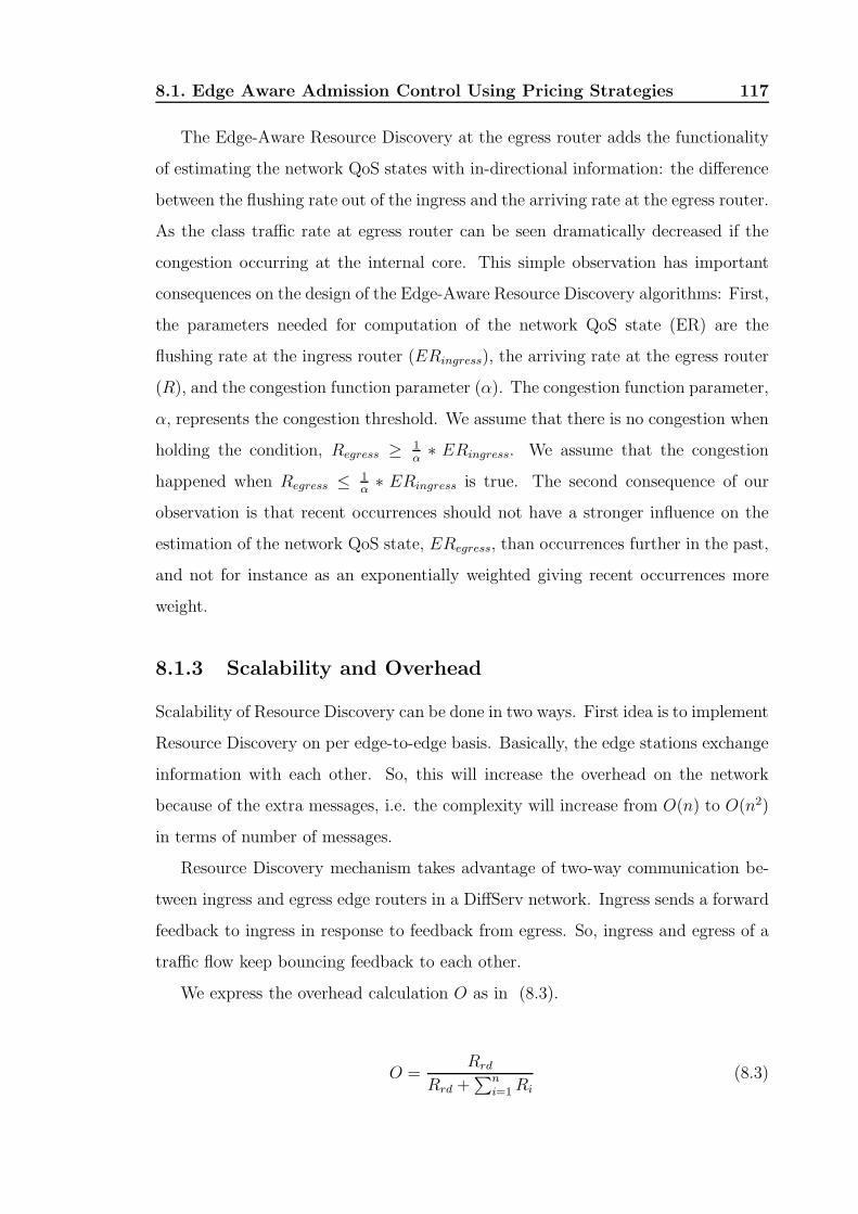
8.1. Edge Aware Admission Control Using Pricing Strategies 117
The Edge-Aware Resource Discovery at the egress router adds the functionality
of estimating the network QoS states with in-directional information: the difference
between the flushing rate out of the ingress and the arriving rate at the egress router.
As the class traffic rate at egress router can be seen dramatically decreased if the
congestion occurring at the internal core. This simple observation has important
consequences on the design of the Edge-Aware Resource Discovery algorithms: First,
the parameters needed for computation of the network QoS state (ER) are the
flushing rate at the ingress router (ERingress), the arriving rate at the egress router
(R), and the congestion function parameter (α). The congestion function parameter,
α, represents the congestion threshold. We assume that there is no congestion when
holding the condition, Regress ≥ 1α∗ ERingress. We assume that the congestion
happened when Regress ≤ 1α∗ ERingress is true. The second consequence of our
observation is that recent occurrences should not have a stronger influence on the
estimation of the network QoS state, ERegress, than occurrences further in the past,
and not for instance as an exponentially weighted giving recent occurrences more
weight.
8.1.3 Scalability and Overhead
Scalability of Resource Discovery can be done in two ways. First idea is to implement
Resource Discovery on per edge-to-edge basis. Basically, the edge stations exchange
information with each other. So, this will increase the overhead on the network
because of the extra messages, i.e. the complexity will increase from O(n) to O(n2)
in terms of number of messages.
Resource Discovery mechanism takes advantage of two-way communication be-
tween ingress and egress edge routers in a DiffServ network. Ingress sends a forward
feedback to ingress in response to feedback from egress. So, ingress and egress of a
traffic flow keep bouncing feedback to each other.
We express the overhead calculation O as in (8.3).
O =Rrd
Rrd +∑n
i=1 Ri
(8.3)

8.1. Edge Aware Admission Control Using Pricing Strategies 118
where Rrd is the RD traffic rate, Ri is for other traffic rate, and n is the number
of classes except RD traffic. In our experiment, we set RD traffic as EF traffic with
20 Kbps bandwidth guarantee, which is around 2% of the total link bandwidth, 1
Mbps. From the (8.3), the overhead is no more than 2%. The DiffServ domain
administrator can adjust RD traffic classification according to the domain states.
For example, the RD packets could be assigned as low priority class (e.g. Bronze
service) and low sending rate if the incoming traffic behaves well; the RD packets
could be assigned as high priority (e.g. Gold or Premium service) and high sending
rate if the network states varies dramatically.
8.1.4 Pricing Strategy
The Edge-Aware Resource Discovery mechanism observes the QoS states or conges-
tion level, c, in the network core and informs the Pricing Strategy function to adjust
its advertised price, p, according to it. The main task of pricing strategy function
is to translate the available network resources to the price per unit resource. The
ideas in developing the pricing strategy are as follows:
• Pricing based on the resource scarcity: The rarer the resource, the higher the
price
• Price increases rapidly or even dramatically: when the resource is below the
threshold of scarce.
The congestion level (Ci) is converted from the difference between the flushing
rate out of the ingress and the arriving rate at the egress (from the edge-aware
resource discovery). If the congestion level is beyond the congestion threshold, the
price will be increased exponentially. If the congestion level is below the congestion
threshold, the price will be decreased linearly.
The aim is that by using the right pricing mechanism, the right admission control
rate is employed and this in turn will produce fairness between the different flows.
In the following subsections we will discuss in details the above two stages func-
tions: a) when Ci is above the congestion threshold, and b) when Ci is below the
congestion threshold.

8.2. Admission Control Model 119
The price function when congestion level is beyond the congestion thresh-
old
At this stage, the price will be increased exponentially. The price function can be
represented as:
Pnew = k ∗ exp(α) ∗ Pold (8.4)
where α is a scaling factor (in our experiments, we set as 4.5) and k is the
adjusting factor (in our experiments, we set as 0.05).
The price function when congestion level is below the congestion thresh-
old
At this stage, the price will be decreased linearly to encourage taking more traffic.
The price function can be represented as:
Pnew = Pold + β (8.5)
where β is the fixed bandwidth value that is considered as a portion of link
capacity. (in our experiments, we set as 5% of link capacity).
8.2 Admission Control Model
The admission control model is based on the price per unit resource (from “internal”
resource discovery) and the traffic requirement (from “external”). In this model,
price and traffic requirements are used to influence the admission control behavior
for the purpose of traffic control.
The Fair Intelligent Admission Control module (FIAC) is an entity that imple-
ments the admission control. The FIAC is comprised of the following components:
1. FIAC-RD interaction module: In the FIAC-RD interaction module, it
takes the price per unit resource (network QoS state information) from the
Resource Discovery module and passes the admission rate to the RD module.
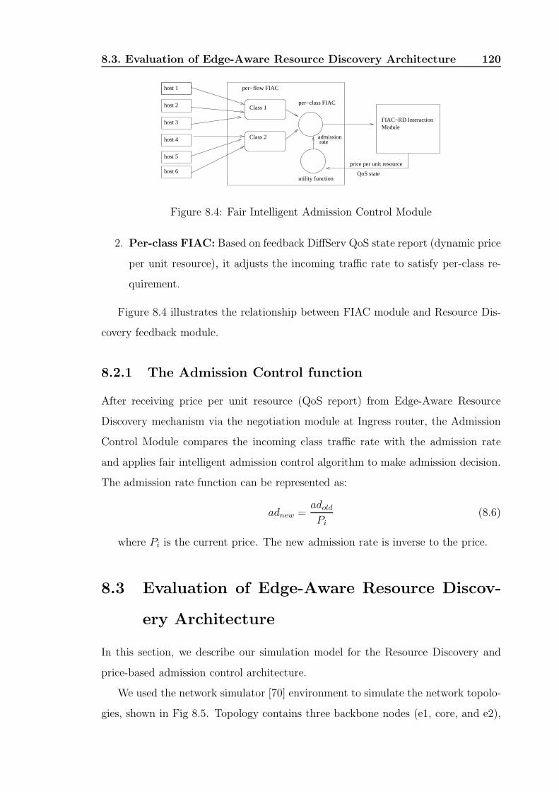
8.3. Evaluation of Edge-Aware Resource Discovery Architecture 120
host 1
host 2
host 3
host 4
host 5
host 6
per−class FIACClass 1
Class 2
per−flow FIAC
FIAC−RD InteractionModule
price per unit resource
QoS state utility function
admission rate
Figure 8.4: Fair Intelligent Admission Control Module
2. Per-class FIAC: Based on feedback DiffServ QoS state report (dynamic price
per unit resource), it adjusts the incoming traffic rate to satisfy per-class re-
quirement.
Figure 8.4 illustrates the relationship between FIAC module and Resource Dis-
covery feedback module.
8.2.1 The Admission Control function
After receiving price per unit resource (QoS report) from Edge-Aware Resource
Discovery mechanism via the negotiation module at Ingress router, the Admission
Control Module compares the incoming class traffic rate with the admission rate
and applies fair intelligent admission control algorithm to make admission decision.
The admission rate function can be represented as:
adnew =adold
Pi(8.6)
where Pi is the current price. The new admission rate is inverse to the price.
8.3 Evaluation of Edge-Aware Resource Discov-
ery Architecture
In this section, we describe our simulation model for the Resource Discovery and
price-based admission control architecture.
We used the network simulator [70] environment to simulate the network topolo-
gies, shown in Fig 8.5. Topology contains three backbone nodes (e1, core, and e2),

8.3. Evaluation of Edge-Aware Resource Discovery Architecture 121
S1
S3
S2
E1 D0E2CORE
100 Mbps 100 Mbps 0.1 Mbps 100 Mbps
S4
Figure 8.5: Simulation Topology: bottle link is CORE to E2
user nodes (s1, s2, s3, and s4), and destination node (d0). All links are full duplex
and point-to-point. The link connecting the backbone nodes, e1→core, is 100 Mb/s,
the links connecting the user nodes to the backbone nodes are 100 Mb/s. The con-
gestion link, core→e2, is 0.1 Mb/s. We use this topology to simulate congestion
from a single bottleneck node. Multiple flows are aggregated to the class. Link
delay is varied in order to aggregate TCP flows with different RTTs. We set up four
classes: Gold, Silver, Bronze, and Best Effort (which claim 40%, 30%, 20%, and
10% individually).
In Experiment 1, we evaluate UDP traffic (in Gold, Silver, Bronze, and Best
effort classes) performance when the congestion happens at core. In Experiment 2,
we study performance of TCP traffic that have different RTT. In Experiment 3, we
study performance of mixing TCP and UDP traffic of classes.
8.3.1 Experiment 1: UDP traffic when the congestion hap-
pens at core
In Experiment 1, we consider four classes, which are Gold, Silver, Bronze, and Best
effort classes. They claim 40%, 30%, 20%, and 10% respectively. Each class has
four UDP flows with same constant bit rate, 200 Kbps. Gold traffic is sent from s1
to d0, the Silver traffic is sent from s2 to d0, the Bronze traffic is sent from s3 to
d0, and Best Effort traffic is sent from s4 to d0. The RD traffic is formed between
E1 and E2.
In Figure 8.6, we plot the goodput results for all classes under traditional DiffServ
and under our Edge Aware Resource Discovery with pricing-control.
Based on this set of plots, we can make following observation. The DiffServ can
not allocate bandwidth fairly for the classes when congestion happens at core due
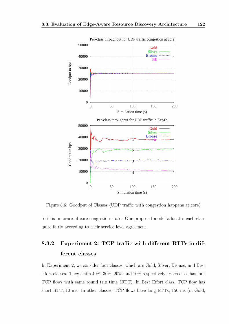
8.3. Evaluation of Edge-Aware Resource Discovery Architecture 122
0
10000
20000
30000
40000
50000
0 50 100 150 200
Goo
dput
in b
ps
Simulation time (s)
Per-class throughput for UDP traffic congestion at core
GoldSilver
BronzeBE
0
10000
20000
30000
40000
50000
0 50 100 150 200
Goo
dput
in b
ps
Simulation time (s)
Per-class throughput for UDP traffic in Exp1b
1
2
3
4
GoldSilver
BronzeBE
Figure 8.6: Goodput of Classes (UDP traffic with congestion happens at core)
to it is unaware of core congestion state. Our proposed model allocates each class
quite fairly according to their service level agreement.
8.3.2 Experiment 2: TCP traffic with different RTTs in dif-
ferent classes
In Experiment 2, we consider four classes, which are Gold, Silver, Bronze, and Best
effort classes. They claim 40%, 30%, 20%, and 10% respectively. Each class has four
TCP flows with same round trip time (RTT). In Best Effort class, TCP flow has
short RTT, 10 ms. In other classes, TCP flows have long RTTs, 150 ms (in Gold,

8.3. Evaluation of Edge-Aware Resource Discovery Architecture 123
0
10000
20000
30000
40000
50000
0 50 100 150 200
Goo
dput
in b
ps
Simulation time (s)
Per-class throughput for TCP traffic with different RTT congestion at core
GoldSilver
BronzeBE
0
10000
20000
30000
40000
50000
0 50 100 150 200
Goo
dput
in b
ps
Simulation time (s)
Per-class throughput for TCP traffic with different RTT
1
2
3
4
GoldSilver
BronzeBE
Figure 8.7: Goodput of Classes (TCP flows with different RTTs)
Silver, and Bronze).
In Figure 8.7, we plot the goodput results for all classes under traditional DiffServ
and under our Edge Aware Resource Discovery with pricing control.
Based on this set of plots, we can make following observation. The DiffServ can
not allocate bandwidth fairly for the classes which have different round trip time
TCP flows. Our proposed model allocates each class quite fairly according to their
service level agreement.

8.3. Evaluation of Edge-Aware Resource Discovery Architecture 124
0
10000
20000
30000
40000
50000
0 50 100 150 200
Goo
dput
in b
ps
Simulation time (s)
Per-class throughput for TCP and UDP traffic congestion at core
GoldSilver
BronzeBE
0
10000
20000
30000
40000
50000
80 100 120 140 160 180 200
Goo
dput
in b
ps
Simulation time (s)
Per-class throughput for TCP and UDP mixed traffic
1
2
3
4
GoldSilver
BronzeBE
Figure 8.8: Goodput of TCP and UDP classes
8.3.3 Experiment 3: mixing TCP and UDP classes
Experiment 3 was designed to study the performance of mixing TCP and UDP
classes in which one class has UDP traffic (in Best Effort) and other three classes
only have TCP traffic (in Gold, Silver, and Bronze). In the simulation, UDP traffic
whose constant bit rate is 1 Mbps so that the bottleneck is oversubscribed. The
other TCP traffic flows (in Gold, Silver, and Bronze) have same RTT, 50 ms.
We investigate the simulation results in terms of bandwidth. The result is shown
in Fig. 8.8. From the results, the TCP flows suffer acute degradation compared to
UDP flow which is in Best effort class.

8.4. Summary 125
However, in Fig. 8.3.3, the distribution of bandwidth is more fair than traditional
DiffServ. That is our proposed model is to preferentially drop UDP packets because
it has higher incoming rate, 1 Mbps, more than its Admission Rate.
8.4 Summary
The chapter proposed a price-based Admission Control scheme in combination with
the Edge-Aware Resource Discovery mechanism over DiffServ architecture. The
scheme intelligently resolves the overloading problem of DiffServ and preserves its
scalability. By using out-of-band discovery feedback loop, our scheme does not need
to modify TCP protocol or IP header format. Numerous suggestions have been
proposed in literature; however, they either involved core router modifications, or
modifications of IP data header, or were inadequate for admission control.
Chapter 9
Conclusions
Motivated by the exponential growth in bandwidth capacity of the Internet, coupled
with the immense growth of broadband adoption by the public, a wide variety of
new online services have been developed. The next wave of innovation services will
be mainly driven by users who are willing to pay for premium quality of service
for application such as audio and video conferences, dynamic visualization, stock
trading, and interactive games which demand stringent QoS responses.
This dissertation sets out to investigate the resource allocation and the quality of
service issues associated of the delivery of the Video-on-Demand (VoD) service. This
led to several subproblems from designing an effective Delayed Multicast protocol,
solving allocation problems, to proposing resource discovery loop and price-based
congestion admission control architecture for providing quality of service.
Overall, the dissertation has achieved its aims by introducing a novel Delayed
Multicast Protocol (DMP), implementing a prototype to investigate the feasibility
of DMP for VoD systems, providing polynomial algorithms for solving resource allo-
cation problems, developing a new enhanced DiffServ architecture and, introducing
price-based admission control to providing QoS for VoD applications.
On DMP, it has demonstrated that a low-cost system can be constructed from
off- -the-shelf components for delivering VoD efficiently. The prototype that was
developed to illustrate its feasibility, indicated that with the same capacity a DMP
system can support many more users than a conventional system.
On theoretical aspects, the dissertation proposed polynomial time algorithms
126

Chapter 9. Conclusions 127
for several of the Delayed Multicast allocation problems where request times were
known in advance. This has implication for planning systems where users can pre-
book their viewing times. Importantly it proved that the problem of allocating
memory and channel bandwidth on a general graph is a NP-complete. Consequently,
it introduced realizable heuristics solutions.
The dissertation offered several algorithms for performing allocation in cases
where request times are not known a priori. It also considered the overall cost of
the system in which not only the bandwidth costs but also the buffering costs are
taken into account. The results provide a sound basis for a comprehensive discussion
on the trade-off between these two cost factors.
On QoS, the dissertation extended the DiffServ framework by implementing a
resource discovery loop between edge routers, using state of the art commercial pro-
grammable routers. It demonstrated that the Enhanced DiffServ QoS architecture
could provide adequate QoS with appropriate admission control mechanism.
On admission control mechanism for DiffServ, the dissertation extended the work
on pricing by Kelly by applying the utility optimization to our Enhanced DiffServ
framework with an appropriate cost function. The result demonstrated that the new
admission control scheme and the Enhanced DiffServ architecture provide fairness
and QoS as expected from the Service level agreement.
It is conceivable that with our novel Delayed Multicast technique, the DMP
protocol, and our proposed QoS framework, high quality, low cost Video-on-Demand
system confined to a DiffServ domain may be realized. However, providing Video-
on-Demand for a more general population over the global Internet scenario requires
further work.
As indicated, the topology of the VoD network plays a crucial role in minizing the
cost the overall system. With a general topology, it is impossible to find a global
optimum solution. One direction is to search for feasible algorithmic support for
more specific but practical topologies. Some extension of our work in Chapter 44
may provide some useful answers.
Another possible direction is to seek good suboptimal solutions by strategically
positioning DMP servers within the overall topology. This may entail solving in-
Chapter 9. Conclusions 128
teresting capacity assignment problems in a new context where bandwidths, delays,
jitters, and costs play important roles.
On another perspective, the creation of the backbone network to support VoD
should be autonomous; it is desirable for DMP servers to discover each other and
form self-organized overlays according to the demand. The problem is how to con-
struct overlay that understands the underlying network, is aware of users’ demands
and where they are located. Partial work has been reported in [73] where novel
techniques have been developed to construct efficient P2P overlay networks.
Another problem is how to introduced DMP servers on demand and automat-
ically that can adapt to the dynamic VoD domain and its users. Programmable
Network devices such as the Serviter [74] could serve the purpose well. Serviter is
a programmable device that allows the introduction of services on demand. It al-
lows partitioning of the host device resources for different services, and also enforces
appropriate QoS along the line of DiffServ but on the device itself. It would be
beneficial to investigate the deployment of Serviter for VoD.
Another issue is to provide VoD across different administrative domains. This in-
troduces further complexity into the problem since it would involve different domain
policies, and different QoS levels. This may entail some form of inter-domain nego-
tiation and management. Recently, an extension of the Border Gateway Protocol
(BGP) has been proposed to provide end-to-end QoS [75]. Initial results indicated
that the enhanced DiffServ architecture can offer end-to-end QoS and facilitates the
use of inter-domain traffic engineering to gain better network performance.
True VoD system must be flexible enough to deal with issues arisen through a
heterogeneous infrastructure across multiple management domains. It is increasingly
recognized that the critical problems with VoD are more ones of economics, policy,
industry structure and tradeoffs among competing players than matters of pure
technology. These issues certainly widen the scope of future investigation.

Bibliography
[1] Hossam El-Gindy, Chi Nguyen, and Antonios Symvonis. Scheduled-Multicast
with Application in Multimedia Networks. In Proceedings of IEEE International
Conference on Networks (ICON 2000), pages 191–198, Singapore, September
2000.
[2] Nikolaos Glinos, Doan B. Hoang, Chi Nguyen, and Antonios Symvonis. Al-
gorithmic support for Video-on-Demand Based on the Delayed-Multicast Pro-
tocol. In Proceedings of the 9th International Colloquium on Structural Infor-
mation and Communication Complexity, pages 133–148, Andros, Greece, June
2002.
[3] Chi Nguyen, Doan B. Hoang, and Antonios Symvonis. Resource Allocation for
Video-on-Demand with “Delayed-Multicast” Protocol. In Proceedings of IEEE
Global Telecommunications Conference (GLOBECOM 2002), pages 1789–1793,
Taipei, Taiwan, November 2002.
[4] Chi Nguyen, Doan B. Hoang, and Antonios Symvonis. Multi-level Caching
With Delayed-Multicast for Video-on-Demand. In Proceedings of Internet and
Multimedia Systems and Applications Conference, pages 699–705, Honolulu,
Hawaii, August 2003.
[5] N. Glinos, D. B. Hoang, C. Nguyen, and A. Symvonis. Video-on-Demand
Based on Delayed-Multicast: Algorithmic Support. The Computer Journal,
47(5):545–559, 2004.
129
Bibliography 130
[6] Chi Nguyen, Doan B. Hoang, and A. Symvonis. Cost-based Optimization for
Video-on-Demand using Delayed-Multicast. In Proceedings of Communication
Systems and Networks, Marbella, Spain, August 2004.
[7] Chi Nguyen, Doan B. Hoang, Ian L. Zhao, and Tal Lavian. Implementation
of a Quality of Service Feedback Control Loop on Programmable Routers. In
Proceedings of IEEE International Conference on Networks 2004 (ICON 2004),
pages 578 – 582, Singapore, November 2004.
[8] David A. Patterson, Garth A. Gibson, and Randy H. Katz. A Case for Redun-
dant Arrays of Inexpensive Disks (RAID). In Proceedings of ACM SIGMOD
Conference, pages 109–116, Chicago, Illinois, June 1988.
[9] Banu Ozden, Rajeev Rastogi, and Avi Silberschatz. On the Storage and Re-
trieval of Continuous Media Data. In 3rd International Conference on Knowl-
edge Management, pages 322–328, Gaithersburg, Maryland, 1994.
[10] Minos Garofalakis, Banu Ozden, and Avi Silberschatz. On Periodic Resource
Scheduling for Continuous Media Databases. The VLDB Journa, 7(4):206–225,
1998.
[11] Mohan Kamath, Krithi Ramamritham, and Don Towsley. Continuous Media
Sharing in Multimedia Database Systems. In Proceedings of the Fourth Inter-
national Conference on Database Systems for Advanced Applications (DASFAA
’95), pages 79–86, Singapore, April 1995.
[12] Weifeng Shi and Shahram Ghandeharizadeh. Buffer Sharing in Video-On-
Demand Servers. In Proceedings of the International Conference on Measure-
ments and Modeling of Computer Systems (SIGMETRICS ’97), pages 13–20,
Seattle, Washington, June 1997.
[13] S. Viswanathan and T. Imielinski. Metropolitan Area Video-on-Demand Service
Using Pyramid Broadcasting. Multimedia Systems, 4(4):197–208, 1996.
[14] C. Aggarwal, J Wolf, and P. S. Yu. A Permutation-Based Pyramid Broadcasting
Scheme for Video-on-Demand Systems. In IEEE International Conference on

Bibliography 131
Multimedia Computing and Systems (ICMCS’96), pages 118–126, Hiroshima,
Japan, June 1996.
[15] Kien A. Hua and Simon Sheu. Skyscraper Broadcasting: A New Broadcasting
Scheme for Metropolitan Video-on-Demand Systems. In Proceedings of ACM
SIGCOMM 1997, pages 89–100, Cannes, France, September 1997.
[16] M. Ramalho. Intra and Inter-Domain Multicast Routing. IEEE Communica-
tions Surveys and Tutorials, 3(1):2–25, First Quarter, 2000.
[17] Hugh W. Holbrook and David R. Cheriton. IP Multicast Channels: EXPRESS
Support for Large-scale Single-source Applications. In Proceedings of ACM
SIGCOMM Conference, pages 65–78, Cambridge, MA, August 1999.
[18] C. Aggarwal, J. Wolf, and P. Yu. On Optimal Batching Policies for Video-
on-Demand Servers. In IEEE Multimedia Computing and Systems Conference,
pages 253–258, Hiroshima, Japan, 1996.
[19] A. Dan, D. Sitaram, and P. Shahabuddin. Scheduling Policies for an On-
Demand Video Server with Batching. In Proceedings of ACM Multimedia Con-
ference, pages 15–23, San Francisco, CA, 1994.
[20] Leana Golubchik, John C.S. Lu, and Richard Muntz. Reducing I/0 Demand in
Video-On-Demand Storage Servers. In Proceedings of the International Con-
ference on Measurements and Modeling of Computer Systems (SIGMETRICS
’95), pages 25–36, Ottawa, Canada, May 1995.
[21] Charu Aggarwal, Joel Wolf, and Philip S. Yu. On Optimal Piggyback Merging
Policies for Video-On-Demand Systems. In Proceedings of the International
Conference on Measurements and Modeling of Computer Systems (SIGMET-
RICS ’96), pages 200–209, Philadelphia, PA, May 1996.
[22] K. A. Hua, Y. Cai, and S. Sheu. Patching: A Multicast Technique for True
Video-on-Demand Services. In Proceedings of ACM Multimedia Conference,
pages 191–200, Bristol, UK, September 1998.
Bibliography 132
[23] Ying Cai, Kien A. Hua, and Khanh Vu. Optimizing Patching Performance. In
Proceedings of SPIE - Multimedia Computing and Networking, pages 204–215,
Santa Clara, CA, January 1999.
[24] Subhabrata Sen, Lixin Gao, Jennifer Rexford, and Don Towsley. Optimal
Patching Schemes for Efficient Multimedia Streaming. In Proceedings of the
9th Intl. Workshop on Network and Operating System Support for Digital Au-
dio and Video, ATT Learning Center, Basking Ridge NJ, June 1999.
[25] Derek Eager, Mary Vernon, and John Zahorjan. Bandwidth Skimming: A
Technique for Cost-Effective Video-on-Demand. In Proceedings of SPIE - Mul-
timedia Computing and Networking, pages 206–215, Santa Jose, CA, January
1999.
[26] Anirban Mahanti, Derek L. Eager, Mary K. Vernon, and David Sundaram-
Stukel. Scalable On-Demand Media Streaming with Packet Loss Recovery. In
Proceedings of ACM SIGCOMM 2001, pages 97–108, New York, NY, August
2001.
[27] John Jannotti, David K. Gifford, Kirk L. Johnson, M. Frans Kaashoek, and Jr.
James W. O’Toole. Overcast: Reliable Multicasting with an Overlay Network.
In Symposium on Operating Systems Design and Implementation, pages 197–
212, San Diego, California, October 2000.
[28] R. Braden, D. Clark, and S. Shenker. Integrated Services in the Internet Ar-
chitecture: An Overview. RFC 1633, IETF, June 1994.
[29] S. Blake, D. Black, M. Carlson, E. Davies, Z. Wang, and W. Weiss. An Archi-
tecture for Differentiated Service. RFC 2475, IETF, December 1998.
[30] A. Mankin, F. Baker, B. Braden, S. Bradner, M. O‘Dell, A. Romanow, A. Wein-
rib, and L. Zhang. Resource ReSerVation Protocol (RSVP) - Version 1 Applica-
bility Statement Some Guidelines on Deployment. RFC 2208, IETF, September
1997.

Bibliography 133
[31] Alan Demers, Srinivasan Keshav, and Scott Shenker. Analysis and Simulation
of a Fair Queueing Algorithm. Internetworking: Research and Experience, 1:3–
26, January 1990.
[32] S. J. Golestani. A Self-clocked Fair Queuing Scheme for Broadband Applica-
tions. In Proceedings of IEEE INFOCOM, pages 636–646, Toronto, Canada,
June 1994.
[33] G. Huston. Next Steps for the IP QoS Architecture. RFC 2990, IETF, Novem-
ber 2000.
[34] Y. Bernet, P. Ford, R. Yavatkar, F. Baker, L. Zhang, M. Speer, R. Braden,
B. Davie, J. Wroclawski, and E. Felstaine. A Framework for Integrated Services
Operation over Diffserv Networks. RFC 2998, IETF, November 2000.
[35] H. de Meer, Piers O’Hanlon, G. Feher, N. Blefari-Melazzi, H. Tschofenig,
G. Karagiannis, D. Partain, V. Rexhepi, and L. Westberg. Analysis of Ex-
isting QoS Solutions. Internet-draft, IETF, November 2002.
[36] M. Grossglauser and D. N. C. Tse. A Framework for Robust Measurement
Based Admission Control. IEEE/ACM Transactions on Networking, 7(3):293–
309, June 1999.
[37] G. Bianchi and N. Blefari-Melazzi. Per Flow Admission Control over AF PHB
Classes. Internet-draft, IETF, March 2000.
[38] M. Gerla, W. Weng, and R. Lo Cigno. Bandwidth feedback control and real time
sources in the Internet. In IEEE GLOBECOM, pages 561–565, San Francisco,
CA, November 2000.
[39] G. Hjalmtysson. Control-on-Demand: An Efficient Approach to Router Pro-
grammability. IEEE Journal on Selected Areas in Communications, 17(9):1549–
1562, September 1999.
[40] David L. Tennenhouse, Jonathan M. Smith, W. David Sincoskie, David J.
Wetherall, and Gary J. Minden. A Survey of Active Network Research. IEEE
Communications Magazine, 35(1):80–86, January 1997.

Bibliography 134
[41] L. Peterson, Y. Gottlieb, M. Hibler, P. Tullmann, J. Lepreau, S. Schwab,
H. Dandelkar, A. Purtell, and J. Hartman. An OS Interface for Active Routers.
IEEE Journal on Selected Areas in Communications, 19(3):473 – 487, March
2001.
[42] David Wetherall. Active network vision and reality: Lessons from a capsule-
based system. In DARPA Active Networks Conference and Exposition
(DANCE’02), pages 25–41, San Francisco, CA, MAY 2002.
[43] T. Lavian and P. Wang. Active networking on a programmable networking plat-
form. In IEEE Conference on Open Architectures and Network Programming
(OPENARCH), Anchorage, Alaska, April 2001.
[44] T. Lavian, P. Wang, F. Travostino, S. Subramanian, Doan B. Hoang, V. Setha-
put, and D. Culler. Enabling Active Flow Manipulation In Silicon-based Net-
work Forwarding Engines. Journal of Communication and Networks, pages
78–87, March 2001.
[45] F. P. Kelly. Charging and Rate Control for Elastic Traffic. European Transac-
tions on Telecommunications, 8:33–37, 1997.
[46] S. H. Low and D. E. Lapsley. Optimization Flow Control - I: Basic Algo-
rithm and Convergence. IEEE/ACM Transactions on Networking, 7(6):861–
875, 1999.
[47] J. K. MacKie-Mason and H. R. Varian. Pricing Congestible Network Resources.
IEEE Journal on Selected Areas in Communications, 13:1141–1149, 1995.
[48] X. Wang and H. Schulzrinne. Pricing Network Resources for Adaptive Applica-
tions in a Differentiated Services Network. In Proceedings of IEEE INFOCOM
2001, pages 943–952, Anchorage, AK, April 2001.
[49] P. Marbach. Priority Service and Max-min Fairness. In Proceedings of IEEE
INFOCOM 2002, pages 23–27, New York, USA, June 2002.
[50] J. MacKie-Mason, L. Murphy, and J. Murphy. Responsive Pricing in the Inter-
net. The Journal of Electronic Publishing, 2(1):279–303, 1997.
Bibliography 135
[51] Ayalvadi J. Ganesh, Koenraad Laevens, and Richard Steinberg. Congestion
Pricing and User Adaptation. In Proceedings of IEEE INFOCOM 2001, pages
959–965, Anchorage, AK, April 2001.
[52] S. Shenker, D. Clark, D. Estrin, and S. Herzog. Pricing in Computer Net-
works: Reshaping the Research Agenda. ACM Computer Communication Re-
view, 26(2):19–43, Feb 1996.
[53] S. Shenker, C. Partridge, and R. Guerin. Specification of Guaranteed Quality
of Service. RFC 2212, IETF, September 1997.
[54] L. Breslau, E. W. Knightly, S. Schenker, I. Stoica, and H. Zhang. Endpoint
Admission Control: Architectural Issues and Performance. In Proceedings of
ACM SIGCOMM 2000, pages 57–69, Stockholm, Sweden, August 2000.
[55] F. P. Kelly, P. B. Key, and S. Zachary. Distributed admission control. IEEE
Journal on Selected Areas in Communications, 18(12):2617–2628, 2000.
[56] Hongliang Yu, Dongdong Zheng, Ben Y. Zhao, and Weimin Zheng. Understand-
ing User Behavior in Large Scale Video-on-Demand Systems. In Proceedings of
EuroSys2006, Leuven, Belgium, April 2006.
[57] S. E. Deering. Host Extensions for IP Multicasting. RFC 1112, IETF, August
1989.
[58] W. Fenner. Internet Group Management Protocol, Version 2. RFC 2236, IETF,
November 1997.
[59] Steven McCanne. Scalable Multimedia Communication: Using IP Multicast
and Lightweight Sessions. IEEE Internet Computing, 3(2):33–45, March/April
1999.
[60] Robert Hill, Balaji, Shyam Pather, and Douglas Niehaus. Temporal Resolution
and Real-Time Extension to Linux. Technical Report ITTC-FY98-TR-11510-
03, University of Kansas, June 1998.

Bibliography 136
[61] Michael R. Garey and David S. Johnson. Computers and Intractibility, A Guide
to the Theory of np-Completeness. W. H. Freeman and Company, New York,
1979.
[62] Richard M. Karp. Reducibility Among Combinatorial Problems. In Complexity
of Computer Computations, pages 85–103, 1972.
[63] George Kingsley Zipf. Human Behavior And The Principle of Least Effort :
An Introduction To Human Ecology. Addison-Wesley, Reading MA, 1949.
[64] S. H. Gary Chan and Fouad Tobagi. Distributed Servers Architecture for Net-
worked Video Services. IEEE/ACM Transaction on Networking, 9(2):125–136,
2001.
[65] B. Wang, S. Sen, M. Adler, and D. Towsley. Optimal Proxy Cache Allocation
For Efficient Streaming Media Distribution. In Proceedings of IEEE INFOCOM
2002, New York, USA, June 2002.
[66] Subhabrata Sen, Jennifer Rexford, and Don Towsley. Proxy Prefix Caching for
Multimedia Streams. In Proceedings of IEEE INFOCOM ’99, pages 1310–1319,
New York, NY, March 1999.
[67] R. Braden, L. Zhang, S. Berson, S. Herzog, and S. Jamin. Resource ReSerVa-
tion Protocol (RSVP) - Version 1 Functional Specification. RFC 2205, IETF,
September 1997.
[68] Y. Bernet, J. Binder, S. Blake, M. Carlson, B. E. Carpenter, S. Keshav,
E. Davies, B. Ohlman, D. Verma, Z. Wang, and W. Weiss. A Framework
for Differentiated Service. Internet-draft, IETF, Fedbruary 1999.
[69] Ming Li. Resource Discovery and Fair Intelligent Admission Control over Scal-
able Internet. PhD thesis, University of Technology Sydney, 2004.
[70] Arnaud Legout, Elan Amir, Hari Balakrishnan, Sandeep Bajaj (PARC), Lee
Breslau, Lars Eggert, Deborah Estrin, Kevin Fall, Sally Floyd, Marc Greis,
Ramesh Govindan, Padma Haldar, Mark Handley, Ahmed Helmy, Tom Hender-
son, John Heidemann, Polly Huang, Chalermek Intanagonwiwat, Satish Kumar,
Bibliography 137
Steven McCanne, Giao Nguyen, Venkat Padmanabhan, Yuri Pryadkin, Reza
Rejaie, Nader Salehi, Puneet Sharma, Scott Shenker, Teck-Lee Tung, Kannan
Varadhan, Vikran Visweswariah, and Haobo Yu. The Network Simulator -
NS-2. Available from: http://www.isi.edu/nsnam/ns/.
[71] Ajay Tirumala, Feng Qin, Jon Dugan, Jim Ferguson, and Kevin Gibbs. Iperf.
Avaliable from: http://dast.nlanr.net/Projects/Iperf/.
[72] I. Stoica and H. Zhang. Providing guaranteed services without per flow man-
agement. In Proceedings of ACM SIGCOMM 1999, pages 81–94, Cambridge,
MA, August 1999.
[73] Hanh Le, Doan B. Hoang, and Andy Simmonds. A Self-Organising Model for
Topology-Aware Overlay Formation. In International Conference on Commu-
nications (ICC 2005), Seoul, Korea, May 2005.
[74] Bushar Yousef, Doan B. Hoang, and G. Rogers. Serviter: A Service-oriented
Programmable Network Platform for Shared Infrastructure. Computer Com-
munications, 29(5):642–659, 2006.
[75] Trung H. Phan and Doan B. Hoang. Extension of BGP to Support Multi-
domain FICC-Diffserv Architecture. In IEEE 20th International Conference
on Advanced Information Networking and Applications (AINA 2006), Vienna,
Austria, April 2006.