scalable ai infrastructure for real-world deep learning use … · 2019-04-02 · netapp verified...
TRANSCRIPT
NetApp Verified Architecture
NetApp ONTAP AI, Powered by NVIDIA
Scalable AI Infrastructure for Real-World Deep Learning Use Cases: Deployment Guide
David Arnette, Amit Borulkar, and Robert Franz, NetApp
October 2018 | NVA-1121-DEPLOY
Abstract This document contains detailed deployment information for the NetApp® ONTAP® AI solution powered by NVIDIA®. This architecture includes a NetApp AFF A800 storage system, four NVIDIA DGX-1™ servers, and two Cisco Nexus 3232C 100Gb Ethernet switches. This document also contains instructions for validating the operation and performance of this system using industry-standard benchmark tools. Detailed design information for this solution can be found in the NetApp Verified Architecture document NVA-1121-DESIGN.
In partnership with
2 NetApp ONTAP AI, Powered by NVIDIA © 2018 NetApp, Inc. All rights reserved.
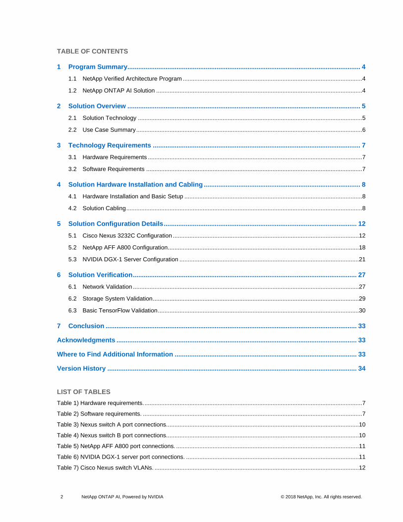
TABLE OF CONTENTS
1 Program Summary................................................................................................................................ 4
1.1 NetApp Verified Architecture Program ............................................................................................................ 4
1.2 NetApp ONTAP AI Solution ............................................................................................................................ 4
2 Solution Overview ................................................................................................................................ 5
2.1 Solution Technology ....................................................................................................................................... 5
2.2 Use Case Summary ........................................................................................................................................ 6
3 Technology Requirements .................................................................................................................. 7
3.1 Hardware Requirements ................................................................................................................................. 7
3.2 Software Requirements .................................................................................................................................. 7
4 Solution Hardware Installation and Cabling ...................................................................................... 8
4.1 Hardware Installation and Basic Setup ........................................................................................................... 8
4.2 Solution Cabling .............................................................................................................................................. 8
5 Solution Configuration Details .......................................................................................................... 12
5.1 Cisco Nexus 3232C Configuration ................................................................................................................ 12
5.2 NetApp AFF A800 Configuration ................................................................................................................... 18
5.3 NVIDIA DGX-1 Server Configuration ............................................................................................................ 21
6 Solution Verification ........................................................................................................................... 27
6.1 Network Validation ........................................................................................................................................ 27
6.2 Storage System Validation ............................................................................................................................ 29
6.3 Basic TensorFlow Validation ......................................................................................................................... 30
7 Conclusion .......................................................................................................................................... 33
Acknowledgments .................................................................................................................................... 33
Where to Find Additional Information .................................................................................................... 33
Version History ......................................................................................................................................... 34
LIST OF TABLES
Table 1) Hardware requirements. ................................................................................................................................... 7
Table 2) Software requirements. .................................................................................................................................... 7
Table 3) Nexus switch A port connections. ................................................................................................................... 10
Table 4) Nexus switch B port connections. ................................................................................................................... 10
Table 5) NetApp AFF A800 port connections. .............................................................................................................. 11
Table 6) NVIDIA DGX-1 server port connections. ........................................................................................................ 11
Table 7) Cisco Nexus switch VLANs. ........................................................................................................................... 12

3 NetApp ONTAP AI, Powered by NVIDIA © 2018 NetApp, Inc. All rights reserved.
Table 8) NetApp AFF A800 interface group configuration. ........................................................................................... 19
Table 9) NVIDIA DGX-1 physical interfaces and VLANs. ............................................................................................. 23
Table 10) NVIDIA DGX-1 bonded interfaces and VLANs. ............................................................................................ 23
Table 11) Validated software versions. ........................................................................................................................ 31
Table 12) TensorFlow general benchmark settings. ..................................................................................................... 31
Table 13) Settings for datasets_num_private_threads in TensorFlow benchmarks. ......................................... 32
LIST OF FIGURES
Figure 1) ONTAP AI solution rack-scale architecture. .................................................................................................... 5
Figure 2) ONTAP AI solution verified architecture. ......................................................................................................... 6
Figure 3) ONTAP AI cabling diagram. ............................................................................................................................ 9
4 NetApp ONTAP AI, Powered by NVIDIA © 2018 NetApp, Inc. All rights reserved.
1 Program Summary
1.1 NetApp Verified Architecture Program
The NetApp Verified Architecture (NVA) program offers customers a verified architecture for NetApp
solutions. NVAs provide customers with a NetApp solution architecture that:
• Is thoroughly tested
• Is prescriptive in nature
• Minimizes deployment risks
• Accelerates time to market
This document is for NetApp and partner solutions engineers and customer strategic decision makers. It
includes specific installation and configuration information for the implementation of this solution as
tested. See the ONTAP AI Design Guide for the architecture design considerations used to determine the
appropriate configuration that meets specific customer requirements.
1.2 NetApp ONTAP AI Solution
NetApp ONTAP® AI proven architecture, powered by NVIDIA DGX supercomputers and NetApp cloud-
connected storage, has been developed and verified by NetApp and NVIDIA. It provides organizations
with a prescriptive architecture that provides the following benefits:
• It eliminates design complexities.
• It permits the independent scaling of compute and storage.
• It can start small and scale seamlessly.
• It provides a range of storage options for various performance and cost points.
ONTAP AI integrates NVIDIA DGX-1 servers with NVIDIA Tesla® V100 graphic processing units (GPUs)
and a NetApp AFF A800 system with state-of-the-art networking. ONTAP AI simplifies AI deployments by
eliminating design complexity and guesswork, enabling enterprises to start small and grow
nondisruptively while intelligently managing data from edge to core to cloud and back.
Figure 1 shows the scalability of the ONTAP AI solution. The AFF A800 system has been verified with
four DGX-1 servers and has demonstrated sufficient performance headroom to support five or more DGX-
1 servers without affecting storage throughput or latency. By adding additional network switches and
storage controller pairs to the ONTAP cluster, the solution can scale to multiple racks to deliver extremely
high throughput and accelerate training and inferencing. This approach offers the flexibility of altering the
ratio of compute to storage independently according to the size of the data lake, the deep learning (DL)
models used, and the required performance metrics.

5 NetApp ONTAP AI, Powered by NVIDIA © 2018 NetApp, Inc. All rights reserved.
Figure 1) ONTAP AI solution rack-scale architecture.
The number of DGX-1 servers and AFF systems that can be placed in a rack depends on the power and
cooling specifications of the rack in use. Final placement of the systems is subject to computational fluid
dynamics analysis, airflow management, and data center design.
2 Solution Overview
DL systems use algorithms that are computationally intensive and uniquely suited to the architecture of
the NVIDIA GPUs. Computations performed in DL algorithms involve an immense volume of matrix
multiplications running in parallel. The highly parallelized architecture of modern GPUs makes them
substantially more efficient than general-purpose CPUs for applications such as DL, where data
processing is done in parallel. Advances in individual and clustered NVIDIA GPU computing architectures
that use the DGX-1 server have made them the preferred platform for workloads such as high-
performance computing (HPC), DL, and analytics. Providing maximized performance for these
environments requires a supporting infrastructure that can keep NVIDIA GPUs fed with data. Dataset
access must therefore be provided at ultra-low latencies with high bandwidth. Ethernet technology has
achieved performance levels that were previously only possible with InfiniBand. Therefore, RDMA over
Converged Ethernet (RoCE) enables easier adoption of these capabilities, because Ethernet
technologies are well understood and widely deployed in every enterprise data center.
2.1 Solution Technology
This solution was validated with one NetApp AFF A800 system, four NVIDIA DGX-1 servers, and two
Cisco Nexus 3232C 100Gb Ethernet switches. Each DGX-1 server was connected to the Nexus switches
with four 100GbE connections that were used for inter-GPU communications using RoCE. Traditional IP
communications for NFS storage access also occur on these links. Each storage controller was
connected to the network switches using four 100GbE links.
Figure 2 shows the basic solution architecture.

6 NetApp ONTAP AI, Powered by NVIDIA © 2018 NetApp, Inc. All rights reserved.
Figure 2) ONTAP AI solution verified architecture.
2.2 Use Case Summary
This solution is intended to support the training and inference phases of the AI and DL pipeline.
Depending on the application, DL models work with large amounts of different types of data (both
structured and unstructured). This difference imposes a varied set of requirements on the underlying
storage system, both in terms of size of the data that is being stored and the number of files in the
dataset.
The high-level storage requirements include the following:
• The ability to store and to retrieve millions of files concurrently
• Storage and retrieval of diverse data objects such as images, audio, video, and time-series data
• Delivery of high parallel performance at low latencies to meet the GPU processing speeds
• Seamless data management and data services that span the edge, the core, and the cloud
For the critical training phase of DL, data is typically copied from the data lake into the training cluster at
regular intervals. That data is then processed repeatedly by the DL model to achieve the desired machine
learning proficiency. The servers that are used in this phase use GPUs to parallelize computations,
creating a tremendous appetite for data. Meeting the raw I/O bandwidth needs is crucial for maintaining
high GPU utilizations.
In the inference phase, the trained models are tested and deployed into production. Alternatively, they
can be fed back to the data lake for further adjustments of input weights. Also, in Internet of Things (IoT)
applications, the models can be deployed to the smart edge devices for initial edge processing.

7 NetApp ONTAP AI, Powered by NVIDIA © 2018 NetApp, Inc. All rights reserved.
3 Technology Requirements
This section covers the hardware and software used in the validation of this solution. All testing
documented in section 6, “Solution Verification,” and the ONTAP AI Design Guide was performed with the
hardware and software indicated here.
Note: The configuration verified in this reference architecture was based on lab equipment availability and not on the requirements or limitations of the hardware tested.
3.1 Hardware Requirements
Table 1 lists the hardware components that were used to validate this solution. The hardware
components used in any particular implementation of this solution might vary according to customer
requirements.
Table 1) Hardware requirements.
Hardware Quantity
NVIDIA DGX-1 GPU servers 4
NetApp AFF A800 system 1 high availability (HA) pair—includes 48x 1.92TB NVMe SSDs
Cisco Nexus 3232C network switches 2
3.2 Software Requirements
Table 2 lists the software components that are required to implement the solution. The software
components used in any particular implementation of the solution might vary according to customer
requirements.
Table 2) Software requirements.
Software Versions
NetApp ONTAP 9.4
Cisco NX-OS switch firmware 7.0(3)I6(1)
NVIDIA DGX-1 operating system Ubuntu 16.04 LTS
Docker container platform 18.03.1-ce [9ee9f40]
Container version netapp_1.7.0.2 based on nvcr.io/nvidia/tensorflow:18.04-py2
Machine learning framework TensorFlow 1.7.0
Horovod 0.11.3
Open MPI 3.1.0
Benchmark software TensorFlow benchmarks [1b1ca8a]

8 NetApp ONTAP AI, Powered by NVIDIA © 2018 NetApp, Inc. All rights reserved.
4 Solution Hardware Installation and Cabling
4.1 Hardware Installation and Basic Setup
All hardware components should be installed in data center racks according to the vendor’s
recommended guidelines. All components used in the validation of this solution fit into a single rack with
room for additional DGX-1 servers. Specific rack power and cooling capacities determine exactly how
many servers can be supported in each rack.
Perform basic setup for each component using the appropriate installation documentation. The following
configuration procedures assume that all components have been installed and configured for
management access and have been upgraded to the software and firmware versions recommended in
this validation. For specific details on basic installation and setup, see the appropriate vendor
documentation. Links are provided in the “Configuration Details” section.
4.2 Solution Cabling
This section contains information about the specific cabling used in the validation of this solution. This
cabling configuration might be modified to meet customer-specific implementation requirements.
The cabling for this solution is shown in Figure 3. DGX-1 physical interface names have been abbreviated
in this drawing for brevity.

9 NetApp ONTAP AI, Powered by NVIDIA © 2018 NetApp, Inc. All rights reserved.
Figure 3) ONTAP AI cabling diagram.

10 NetApp ONTAP AI, Powered by NVIDIA © 2018 NetApp, Inc. All rights reserved.
Network Switch Port Connections
Table 3 shows the switch connections for switch A.
Table 3) Nexus switch A port connections.
Switch name Port Name Connected Device and Port
ONTAPAI-SW-A Eth1/1 A800-01:e2a
ONTAPAI-SW-A Eth1/2 A800-01:e4a
ONTAPAI-SW-A Eth1/3 A800-02:e2a
ONTAPAI-SW-A Eth1/4 A800-02:e4a
ONTAPAI-SW-A Eth1/11 ONTAPAI-SW-B:Eth1/11
ONTAPAI-SW-A Eth1/12 ONTAPAI-SW-B:Eth1/12
ONTAPAI-SW-A Eth1/13 ONTAPAI-SW-B:Eth1/13
ONTAPAI-SW-A Eth1/14 ONTAPAI-SW-B:Eth1/14
ONTAPAI-SW-A Eth1/25 DGX1-A:enp5s0
ONTAPAI-SW-A Eth1/26 DGX1-A:enp12s0
ONTAPAI-SW-A Eth1/27 DGX1-B:enp5s0
ONTAPAI-SW-A Eth1/28 DGX1-B:enp12s0
ONTAPAI-SW-A Eth1/29 DGX1-C:enp5s0
ONTAPAI-SW-A Eth1/30 DGX1-C:enp12s0
ONTAPAI-SW-A Eth1/31 DGX1-D:enp5s0
ONTAPAI-SW-A Eth1/32 DGX1-D:enp12s0
Table 4 shows the switch connections for switch B.
Table 4) Nexus switch B port connections.
Switch name Port Name Connected Device and Port
ONTAPAI-SW-B Eth1/1 A800-01:e2b
ONTAPAI-SW-B Eth1/2 A800-01:e4b
ONTAPAI-SW-B Eth1/3 A800-02:e2b
ONTAPAI-SW-B Eth1/4 A800-02:e4b
ONTAPAI-SW-B Eth1/11 ONTAPAI-SW-A:Eth1/11
ONTAPAI-SW-B Eth1/12 ONTAPAI-SW-A:Eth1/12
ONTAPAI-SW-B Eth1/13 ONTAPAI-SW-A:Eth1/13
ONTAPAI-SW-B Eth1/14 ONTAPAI-SW-A:Eth1/14
ONTAPAI-SW-B Eth1/25 DGX1-A:enp132s0
ONTAPAI-SW-B Eth1/26 DGX1-A:enp139s0
ONTAPAI-SW-B Eth1/27 DGX1-B:enp132s0
ONTAPAI-SW-B Eth1/28 DGX1-B:enp139s0
ONTAPAI-SW-B Eth1/29 DGX1-C:enp132s0
ONTAPAI-SW-B Eth1/30 DGX1-C:enp139s0
ONTAPAI-SW-B Eth1/31 DGX1-D:enp132s0
ONTAPAI-SW-B Eth1/32 DGX1-D:enp139s0

11 NetApp ONTAP AI, Powered by NVIDIA © 2018 NetApp, Inc. All rights reserved.
Storage Controller Port Connections
Table 5 shows the ports that are connected to the NetApp AFF A800 storage system.
Table 5) NetApp AFF A800 port connections.
Controller name Port Name Connected Device and Port
A800-01 e0M management switch
A800-01 e0a A800-02:e0a
A800-01 e1a A800-02:e1a
A800-01 e2a ONTAPAI-SW-A:eth1/1
A800-01 e2b ONTAPAI-SW-B:eth1/1
A800-01 e4a ONTAPAI-SW-A:eth1/2
A800-01 e4b ONTAPAI-SW-B:eth1/2
A800-02 e0M management switch
A800-02 e0a A800-01:e0a
A800-02 e1a A800-01:e1a
A800-02 e2a ONTAPAI-SW-A:eth1/3
A800-02 e2b ONTAPAI-SW-B:eth1/3
A800-02 e4a ONTAPAI-SW-A:eth1/4
A800-02 e4b ONTAPAI-SW-B:eth1/4
DGX-1 Network Port Connections
Table 6 shows the network ports connected on each of the four DGX-1 servers.
Table 6) NVIDIA DGX-1 server port connections.
Controller Name Port Name Connected Device and Port
DGX1-A enp1s0 management switch
DGX1-A enp5s0 ONTAPAI-SW-A:eth1/25
DGX1-A enp12s0 ONTAPAI-SW-A:eth1/26
DGX1-A enp132s0 ONTAPAI-SW-B:eth1/25
DGX1-A enp139s0 ONTAPAI-SW-B:eth1/26
DGX1-B enp1s0 management switch
DGX1-B enp5s0 ONTAPAI-SW-A:eth1/27
DGX1-B enp12s0 ONTAPAI-SW-A:eth1/27
DGX1-B enp132s0 ONTAPAI-SW-B:eth1/28
DGX1-B enp139s0 ONTAPAI-SW-B:eth1/28
DGX1-C enp1s0 management switch
DGX1-C enp5s0 ONTAPAI-SW-A:eth1/29
DGX1-C enp12s0 ONTAPAI-SW-A:eth1/29
DGX1-C enp132s0 ONTAPAI-SW-B:eth1/30
DGX1-C enp139s0 ONTAPAI-SW-B:eth1/30
DGX1-D enp1s0 management switch
DGX1-D enp5s0 ONTAPAI-SW-A:eth1/31

12 NetApp ONTAP AI, Powered by NVIDIA © 2018 NetApp, Inc. All rights reserved.
DGX1-D enp12s0 ONTAPAI-SW-A:eth1/31
DGX1-D enp132s0 ONTAPAI-SW-B:eth1/32
DGX1-D enp139s0 ONTAPAI-SW-B:eth1/32
5 Solution Configuration Details
This section contains specific configuration details and instructions for completing the configuration of the
solution components. The following tasks are described:
• Cisco Nexus 3232C configuration
• NetApp AFF A800 configuration
• NVIDIA DGX-1 server configuration
5.1 Cisco Nexus 3232C Configuration
Basic Setup
Detailed instructions for the installation and basic setup of Cisco Nexus switches can be found in the
Cisco Nexus 3000 Series Hardware Installation Guide.
After the switches are configured for management access and cabled according to the cabling guidelines
indicated earlier, the following configuration procedures create a configuration similar to the one tested in
this solution validation.
Enable Features
The following features must be enabled for this solution:
• Link Aggregation Control Protocol (LACP)
• Link Layer Discovery Protocol (LLDP)
To enable the required Nexus features, complete the following steps:
Log in as admin.
Run the following commands:
config t
feature lacp
feature lldp
Create VLANs
The virtual LANs (VLANs) listed in Table 7 were created for this solution.
Table 7) Cisco Nexus switch VLANs.
VLAN ID VLAN Name
3091 ROCE-VLAN-01
3092 ROCE-VLAN-02
3093 ROCE-VLAN-03
3094 ROCE-VLAN-04
3111 NFS-VLAN-01
3112 NFS-VLAN-02

13 NetApp ONTAP AI, Powered by NVIDIA © 2018 NetApp, Inc. All rights reserved.
To create the VLANs required for this solution, run the following commands from the global configuration
prompt:
vlan 3091
name ROCE-VLAN-01
vlan 3092
name ROCE-VLAN-02
vlan 3093
name ROCE-VLAN-03
vlan 3094
name ROCE-VLAN-04
vlan 3111
name NFS-VLAN-01
vlan 3112
name NFS-VLAN-02
Configure QoS
The QoS configuration settings enable the lossless Ethernet transport used by RoCE and define the
bandwidth allocation for each traffic class. Use the following procedure to create the QoS configuration:
Create class maps of type qos to apply a class of service (CoS) value to input traffic.
class-map type qos match-all class_RoCE
match cos 3
class-map type qos match-all class_control
match cos 5-7
Create a policy map of type qos to set the QoS group for each class.
policy-map type qos RoCE-marking-policy
class class_control
set qos-group 7
class class_RoCE
set qos-group 3
class class-default
set qos-group 0
Create a queuing type policy map to allocate bandwidth for each traffic class.
policy-map type queuing RoCE-queue-policy
class type queuing c-out-8q-q7
priority level 1
class type queuing c-out-8q-q6
bandwidth remaining percent 0
class type queuing c-out-8q-q5
bandwidth remaining percent 0
class type queuing c-out-8q-q4
bandwidth remaining percent 0
class type queuing c-out-8q-q3
bandwidth remaining percent 90
class type queuing c-out-8q-q2
bandwidth remaining percent 0
class type queuing c-out-8q-q1
bandwidth remaining percent 0
class type queuing c-out-8q-q-default
bandwidth remaining percent 10
Create a network-qos policy map to define the maximum transmission unit (MTU) and priority-based flow control (PFC) pause settings for the relevant queues.
policy-map type network-qos RoCE-nq-policy
class type network-qos c-8q-nq7
mtu 1500
class type network-qos c-8q-nq-default
mtu 9216
class type network-qos c-8q-nq3
mtu 9216
pause pfc-cos 3
14 NetApp ONTAP AI, Powered by NVIDIA © 2018 NetApp, Inc. All rights reserved.
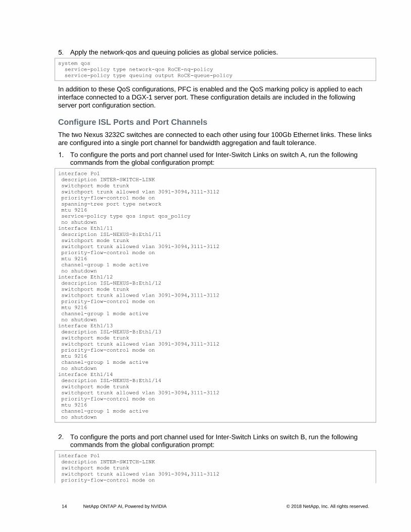
Apply the network-qos and queuing policies as global service policies.
system qos
service-policy type network-qos RoCE-nq-policy
service-policy type queuing output RoCE-queue-policy
In addition to these QoS configurations, PFC is enabled and the QoS marking policy is applied to each
interface connected to a DGX-1 server port. These configuration details are included in the following
server port configuration section.
Configure ISL Ports and Port Channels
The two Nexus 3232C switches are connected to each other using four 100Gb Ethernet links. These links
are configured into a single port channel for bandwidth aggregation and fault tolerance.
To configure the ports and port channel used for Inter-Switch Links on switch A, run the following commands from the global configuration prompt:
interface Po1
description INTER-SWITCH-LINK
switchport mode trunk
switchport trunk allowed vlan 3091-3094,3111-3112
priority-flow-control mode on
spanning-tree port type network
mtu 9216
service-policy type qos input qos_policy
no shutdown
interface Eth1/11
description ISL-NEXUS-B:Eth1/11
switchport mode trunk
switchport trunk allowed vlan 3091-3094,3111-3112
priority-flow-control mode on
mtu 9216
channel-group 1 mode active
no shutdown
interface Eth1/12
description ISL-NEXUS-B:Eth1/12
switchport mode trunk
switchport trunk allowed vlan 3091-3094,3111-3112
priority-flow-control mode on
mtu 9216
channel-group 1 mode active
no shutdown
interface Eth1/13
description ISL-NEXUS-B:Eth1/13
switchport mode trunk
switchport trunk allowed vlan 3091-3094,3111-3112
priority-flow-control mode on
mtu 9216
channel-group 1 mode active
no shutdown
interface Eth1/14
description ISL-NEXUS-B:Eth1/14
switchport mode trunk
switchport trunk allowed vlan 3091-3094,3111-3112
priority-flow-control mode on
mtu 9216
channel-group 1 mode active
no shutdown
To configure the ports and port channel used for Inter-Switch Links on switch B, run the following commands from the global configuration prompt:
interface Po1
description INTER-SWITCH-LINK
switchport mode trunk
switchport trunk allowed vlan 3091-3094,3111-3112
priority-flow-control mode on
15 NetApp ONTAP AI, Powered by NVIDIA © 2018 NetApp, Inc. All rights reserved.
spanning-tree port type network
mtu 9216
service-policy type qos input qos_policy
no shutdown
interface Eth1/11
description ISL-NEXUS-A:Eth1/11
switchport mode trunk
switchport trunk allowed vlan 3091-3094,3111-3112
priority-flow-control mode on
mtu 9216
channel-group 1 mode active
no shutdown
interface Eth1/12
description ISL-NEXUS-A:Eth1/12
switchport mode trunk
switchport trunk allowed vlan 3091-3094,3111-3112
priority-flow-control mode on
mtu 9216
channel-group 1 mode active
no shutdown
interface Eth1/13
description ISL-NEXUS-A:Eth1/13
switchport mode trunk
switchport trunk allowed vlan 3091-3094,3111-3112
priority-flow-control mode on
mtu 9216
channel-group 1 mode active
no shutdown
interface Eth1/14
description ISL-NEXUS-A:Eth1/14
switchport mode trunk
switchport trunk allowed vlan 3091-3094,3111-3112
priority-flow-control mode on
mtu 9216
channel-group 1 mode active
no shutdown
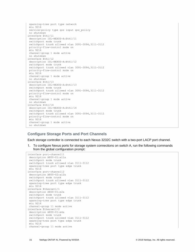
Configure Storage Ports and Port Channels
Each storage controller is connected to each Nexus 3232C switch with a two-port LACP port channel.
To configure Nexus ports for storage system connections on switch A, run the following commands from the global configuration prompt:
interface port-channel11
description A800-01:a11a
switchport mode trunk
switchport trunk allowed vlan 3111-3112
spanning-tree port type edge trunk
mtu 9216
interface port-channel12
description A800-02:a12a
switchport mode trunk
switchport trunk allowed vlan 3111-3112
spanning-tree port type edge trunk
mtu 9216
interface Ethernet1/1
description A800-01:e2a
switchport mode trunk
switchport trunk allowed vlan 3111-3112
spanning-tree port type edge trunk
mtu 9216
channel-group 11 mode active
interface Ethernet1/2
description A800-01:e4a
switchport mode trunk
switchport trunk allowed vlan 3111-3112
spanning-tree port type edge trunk
mtu 9216
channel-group 11 mode active

16 NetApp ONTAP AI, Powered by NVIDIA © 2018 NetApp, Inc. All rights reserved.
interface Ethernet1/3
description A800-02:e2a
switchport mode trunk
switchport trunk allowed vlan 3111-3112
spanning-tree port type edge trunk
mtu 9216
channel-group 12 mode active
interface Ethernet1/4
description A800-02:e4a
switchport mode trunk
switchport trunk allowed vlan 3111-3112
spanning-tree port type edge trunk
mtu 9216
channel-group 12 mode active
To configure Nexus ports for storage system connections on switch B, run the following commands from the global configuration prompt:
interface port-channel21
description A800-01:a21a
switchport mode trunk
switchport trunk allowed vlan 3111-3112
spanning-tree port type edge trunk
mtu 9216
interface port-channel22
description A800-02:a22a
switchport mode trunk
switchport trunk allowed vlan 3111-3112
spanning-tree port type edge trunk
mtu 9216
interface Ethernet1/1
description A800-01:e2b
switchport mode trunk
switchport trunk allowed vlan 3111-3112
spanning-tree port type edge trunk
mtu 9216
channel-group 21 mode active
interface Ethernet1/2
description A800-01:e4b
switchport mode trunk
switchport trunk allowed vlan 3111-3112
spanning-tree port type edge trunk
mtu 9216
channel-group 21 mode active
interface Ethernet1/3
description A800-02:e2b
switchport mode trunk
switchport trunk allowed vlan 3111-3112
spanning-tree port type edge trunk
mtu 9216
channel-group 22 mode active
interface Ethernet1/4
description A800-02:e4b
switchport mode trunk
switchport trunk allowed vlan 3111-3112
spanning-tree port type edge trunk
mtu 9216
channel-group 22 mode active
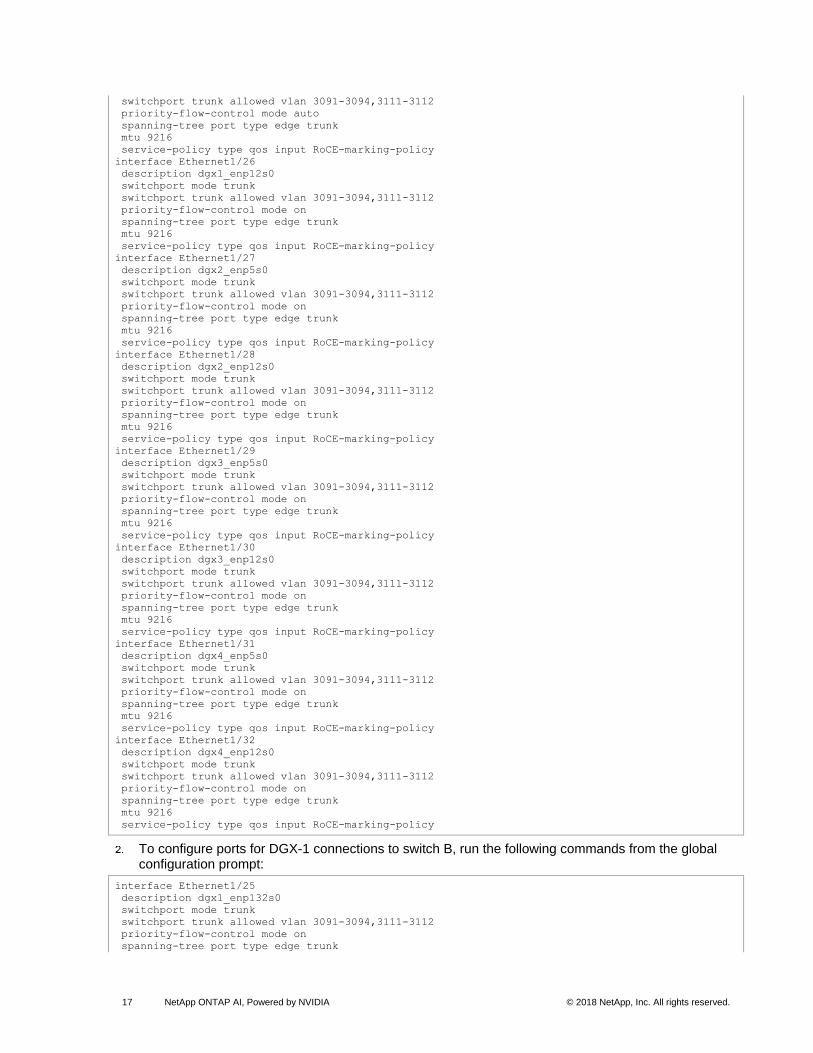
Configure Host Ports
Ports connected to a DGX-1 server are used as individual ports and are not configured as port channels.
To configure ports for DGX-1 connections to switch A, run the following commands from the global configuration prompt:
interface Ethernet1/25
description dgx1_enp5s0
switchport mode trunk
17 NetApp ONTAP AI, Powered by NVIDIA © 2018 NetApp, Inc. All rights reserved.
switchport trunk allowed vlan 3091-3094,3111-3112
priority-flow-control mode auto
spanning-tree port type edge trunk
mtu 9216
service-policy type qos input RoCE-marking-policy
interface Ethernet1/26
description dgx1_enp12s0
switchport mode trunk
switchport trunk allowed vlan 3091-3094,3111-3112
priority-flow-control mode on
spanning-tree port type edge trunk
mtu 9216
service-policy type qos input RoCE-marking-policy
interface Ethernet1/27
description dgx2_enp5s0
switchport mode trunk
switchport trunk allowed vlan 3091-3094,3111-3112
priority-flow-control mode on
spanning-tree port type edge trunk
mtu 9216
service-policy type qos input RoCE-marking-policy
interface Ethernet1/28
description dgx2_enp12s0
switchport mode trunk
switchport trunk allowed vlan 3091-3094,3111-3112
priority-flow-control mode on
spanning-tree port type edge trunk
mtu 9216
service-policy type qos input RoCE-marking-policy
interface Ethernet1/29
description dgx3_enp5s0
switchport mode trunk
switchport trunk allowed vlan 3091-3094,3111-3112
priority-flow-control mode on
spanning-tree port type edge trunk
mtu 9216
service-policy type qos input RoCE-marking-policy
interface Ethernet1/30
description dgx3_enp12s0
switchport mode trunk
switchport trunk allowed vlan 3091-3094,3111-3112
priority-flow-control mode on
spanning-tree port type edge trunk
mtu 9216
service-policy type qos input RoCE-marking-policy
interface Ethernet1/31
description dgx4_enp5s0
switchport mode trunk
switchport trunk allowed vlan 3091-3094,3111-3112
priority-flow-control mode on
spanning-tree port type edge trunk
mtu 9216
service-policy type qos input RoCE-marking-policy
interface Ethernet1/32
description dgx4_enp12s0
switchport mode trunk
switchport trunk allowed vlan 3091-3094,3111-3112
priority-flow-control mode on
spanning-tree port type edge trunk
mtu 9216
service-policy type qos input RoCE-marking-policy
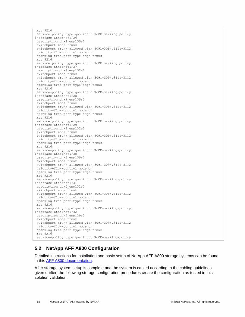
To configure ports for DGX-1 connections to switch B, run the following commands from the global configuration prompt:
interface Ethernet1/25
description dgx1_enp132s0
switchport mode trunk
switchport trunk allowed vlan 3091-3094,3111-3112
priority-flow-control mode on
spanning-tree port type edge trunk
18 NetApp ONTAP AI, Powered by NVIDIA © 2018 NetApp, Inc. All rights reserved.
mtu 9216
service-policy type qos input RoCE-marking-policy
interface Ethernet1/26
description dgx1_enp139s0
switchport mode trunk
switchport trunk allowed vlan 3091-3094,3111-3112
priority-flow-control mode on
spanning-tree port type edge trunk
mtu 9216
service-policy type qos input RoCE-marking-policy
interface Ethernet1/27
description dgx2_enp132s0
switchport mode trunk
switchport trunk allowed vlan 3091-3094,3111-3112
priority-flow-control mode on
spanning-tree port type edge trunk
mtu 9216
service-policy type qos input RoCE-marking-policy
interface Ethernet1/28
description dgx2_enp139s0
switchport mode trunk
switchport trunk allowed vlan 3091-3094,3111-3112
priority-flow-control mode on
spanning-tree port type edge trunk
mtu 9216
service-policy type qos input RoCE-marking-policy
interface Ethernet1/29
description dgx3_enp132s0
switchport mode trunk
switchport trunk allowed vlan 3091-3094,3111-3112
priority-flow-control mode on
spanning-tree port type edge trunk
mtu 9216
service-policy type qos input RoCE-marking-policy
interface Ethernet1/30
description dgx3_enp139s0
switchport mode trunk
switchport trunk allowed vlan 3091-3094,3111-3112
priority-flow-control mode on
spanning-tree port type edge trunk
mtu 9216
service-policy type qos input RoCE-marking-policy
interface Ethernet1/31
description dgx4_enp132s0
switchport mode trunk
switchport trunk allowed vlan 3091-3094,3111-3112
priority-flow-control mode on
spanning-tree port type edge trunk
mtu 9216
service-policy type qos input RoCE-marking-policy
interface Ethernet1/32
description dgx4_enp139s0
switchport mode trunk
switchport trunk allowed vlan 3091-3094,3111-3112
priority-flow-control mode on
spanning-tree port type edge trunk
mtu 9216
service-policy type qos input RoCE-marking-policy
5.2 NetApp AFF A800 Configuration
Detailed instructions for installation and basic setup of NetApp AFF A800 storage systems can be found
in this AFF A800 documentation.
After storage system setup is complete and the system is cabled according to the cabling guidelines
given earlier, the following storage configuration procedures create the configuration as tested in this
solution validation.

19 NetApp ONTAP AI, Powered by NVIDIA © 2018 NetApp, Inc. All rights reserved.
Manage the Default Broadcast Domain
Broadcast domains are used to group L2-adjacent ports together for failover purposes. Logical interfaces
(LIFs) automatically fail over to another port in the same broadcast domain if a link failure occurs. LIFs
attempt to fail over to another port on the same controller if possible, or to an appropriate port on another
controller if necessary. Because each VLAN represents a separate L2 subnet, a storage broadcast
domain is created for each VLAN.
By default, all network ports are included in the default broadcast domain. Network ports used for data
services (e2a, e2b, e4a, and e4b) should be removed from the default broadcast domain, leaving just the
management network ports (e0M). To perform this task, run the following commands:
broadcast-domain remove-ports -broadcast-domain Default -ports A800-01:e2a,A800-01:e2b,A800-
01:e4a,A800-01:e4b, A800-02:e2a,A800-02:e2b,A800-02:e4a,A800-02:e4b
Create Data Aggregates
This solution was validated using the default aggregate configuration for the AFF A800 in which each
controller hosts a single data aggregate created by using 47 disk partitions. If the data aggregates were
not created during initial cluster setup, run the following commands to create two data aggregates:
aggr create -aggregate aggr1_node01 -node A800-01 -diskcount 47
aggr create -aggregate aggr1_node02 -node A800-02 -diskcount 47
Note that NetApp ONTAP partitions each solid-state drive (SSD) into two small root partitions and two
larger data partitions, with one of each allocated to each controller. The root partitions are used for the
root aggregate for the controller node, and the larger partitions are used for data aggregates. Root
aggregates are created automatically during initial setup, and one root partition is kept as a spare on each
controller. When creating data aggregates, leave at least one data partition unused as a spare on each
controller to provide redundancy if a drive failure occurs.
Create Interface Groups and Set the MTU
Interface groups are used to bond multiple storage system network ports together for bandwidth
aggregation and fault tolerance. Table 8 shows the interface groups that were created on the storage
system.
Table 8) NetApp AFF A800 interface group configuration.
Controller Name
Interface Groups
Distribution Function Mode MTU Ports
A800-01 a11a Sequential (round-robin) multimode_lacp 9000 e2a,e4a
A800-01 a21a Sequential (round-robin) multimode_lacp 9000 e2b,e4b
A800-02 a12a Sequential (round-robin) multimode_lacp 9000 e2a,e4a
A800-02 a22a Sequential (round-robin) multimode_lacp 9000 e2b,e4b
Run the following commands to create the interface groups (ifgrps) and configure the MTU:
ifgrp create -node A800-01 -ifgrp a11a -distr-func sequential -mode multimode_lacp
ifgrp add-port -node A800-01 -ifgrp a11a -port e2a
ifgrp add-port -node A800-01 -ifgrp a11a -port e4a
ifgrp create -node A800-01 -ifgrp a21a -distr-func sequential -mode multimode_lacp
ifgrp add-port -node A800-01 -ifgrp a21a -port e2b
ifgrp add-port -node A800-01 -ifgrp a21a -port e4b
ifgrp create -node A800-02 -ifgrp a12a -distr-func sequential -mode multimode_lacp
ifgrp add-port -node A800-02 -ifgrp a12a -port e2a
ifgrp add-port -node A800-02 -ifgrp a12a -port e4a
ifgrp create -node A800-02 -ifgrp a22a -distr-func sequential -mode multimode_lacp
ifgrp add-port -node A800-02 -ifgrp a22a -port e2b
ifgrp add-port -node A800-02 -ifgrp a22a -port e4b

20 NetApp ONTAP AI, Powered by NVIDIA © 2018 NetApp, Inc. All rights reserved.
network port modify –node A800-01 -port a11a –mtu 9000
network port modify –node A800-01 -port a21a –mtu 9000
network port modify –node A800-02 -port a12a –mtu 9000
network port modify –node A800-02 -port a22a –mtu 9000
Create VLAN ports and set MTU
Create Storage VLANs
Two separate NFS VLANs were used in this solution to create two independent paths through the
network for each host if needed. Each VLAN was created on each of the two interface groups on each
controller, providing a total of four possible failover targets for each VLAN. To configure the storage
VLANs used in the validation of this solution, run the following commands:
network port vlan create –node A800-01 -vlan-name a11a-3111
network port vlan create –node A800-01 -vlan-name a21a-3111
network port vlan create –node A800-01 -vlan-name a11a-3112
network port vlan create –node A800-01 -vlan-name a21a-3112
network port vlan create –node A800-02 -vlan-name a12a-3111
network port vlan create –node A800-02 -vlan-name a22a-3111
network port vlan create –node A800-02 -vlan-name a12a-3112
network port vlan create –node A800-02 -vlan-name a22a-3112
Create or Modify Broadcast Domains
To create broadcast domains for the newly created VLANs and assign the appropriate ports, run the
following commands:
broadcast-domain create -broadcast-domain NFS-A -mtu 9000
broadcast-domain create -broadcast-domain NFS-B -mtu 9000
broadcast-domain add-ports -broadcast-domain NFS-A -ports A800-01:a11a-3111, A800-01:a21a-3111,
A800-02:a12a-3111, A800-02:a22a-3111
broadcast-domain add-ports -broadcast-domain NFS-B -ports A800-01:a11a-3112, A800-01:a21a-3112,
A800-02:a12a-3112, A800-02:a22a-3112
Create an SVM
Data access for ONTAP systems is provided by a storage virtual machine (SVM). A data SVM must be
created with the appropriate protocols before hosts can access the storage system. To create an SVM
with the NFS protocol and enable access to the data aggregates, run the following commands:
vserver create –vserver AI-SVM –rootvolume AI_SVM_rootvol –aggregate aggr1_node01 –rootvolume-
security-style unix
vserver modify –vserver AI-SVM –aggr-list aggr1_node01,aggr1_node02 -allowed-protocols nfs
Create LIFs
LIFs are the IP addresses that client servers use to mount NFS exports. For this solution, a single LIF is
created on each interface group on each controller, providing for discrete potential mount points. To
create the LIFs used in this solution, run the following commands:
network interface create -vserver AI-SVM -lif NFS-01-A -role data -data-protocol nfs -home-node
A800-01 -home-port a11a-3111 -address 172.31.11.11 -netmask 255.255.255.0 –status-admin up
network interface create -vserver AI-SVM -lif NFS-01-B -role data -data-protocol nfs -home-node
A800-01 -home-port a21a-3112 -address 172.31.12.11 -netmask 255.255.255.0 –status-admin up
network interface create -vserver AI-SVM -lif NFS-02-A -role data -data-protocol nfs -home-node
A800-02 -home-port a12a-3111 -address 172.31.11.12 -netmask 255.255.255.0 –status-admin up
network interface create -vserver AI-SVM -lif NFS-02-B -role data -data-protocol nfs -home-node
A800-02 -home-port a22a-3112 -address 172.31.12.12 -netmask 255.255.255.0 –status-admin up
21 NetApp ONTAP AI, Powered by NVIDIA © 2018 NetApp, Inc. All rights reserved.
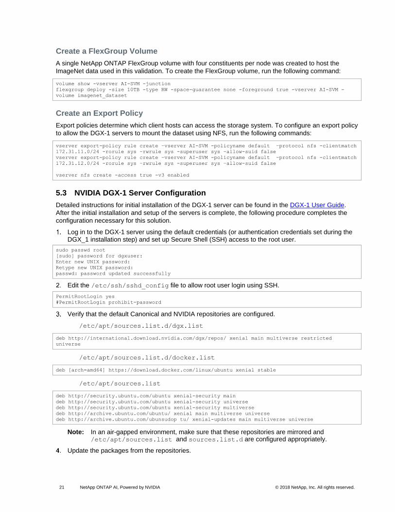
Create a FlexGroup Volume
A single NetApp ONTAP FlexGroup volume with four constituents per node was created to host the
ImageNet data used in this validation. To create the FlexGroup volume, run the following command:
volume show -vserver AI-SVM -junction
flexgroup deploy -size 10TB -type RW -space-guarantee none -foreground true -vserver AI-SVM -
volume imagenet_dataset
Create an Export Policy
Export policies determine which client hosts can access the storage system. To configure an export policy
to allow the DGX-1 servers to mount the dataset using NFS, run the following commands:
vserver export-policy rule create –vserver AI-SVM -policyname default –protocol nfs -clientmatch
172.31.11.0/24 -rorule sys –rwrule sys -superuser sys –allow-suid false
vserver export-policy rule create –vserver AI-SVM -policyname default –protocol nfs -clientmatch
172.31.12.0/24 -rorule sys –rwrule sys -superuser sys –allow-suid false
vserver nfs create -access true -v3 enabled
5.3 NVIDIA DGX-1 Server Configuration
Detailed instructions for initial installation of the DGX-1 server can be found in the DGX-1 User Guide.
After the initial installation and setup of the servers is complete, the following procedure completes the
configuration necessary for this solution.
Log in to the DGX-1 server using the default credentials (or authentication credentials set during the DGX_1 installation step) and set up Secure Shell (SSH) access to the root user.
sudo passwd root
[sudo] password for dgxuser:
Enter new UNIX password:
Retype new UNIX password:
passwd: password updated successfully
Edit the /etc/ssh/sshd_config file to allow root user login using SSH.
PermitRootLogin yes
#PermitRootLogin prohibit-password
Verify that the default Canonical and NVIDIA repositories are configured.
/etc/apt/sources.list.d/dgx.list
deb http://international.download.nvidia.com/dgx/repos/ xenial main multiverse restricted
universe
/etc/apt/sources.list.d/docker.list
deb [arch=amd64] https://download.docker.com/linux/ubuntu xenial stable
/etc/apt/sources.list
deb http://security.ubuntu.com/ubuntu xenial-security main
deb http://security.ubuntu.com/ubuntu xenial-security universe
deb http://security.ubuntu.com/ubuntu xenial-security multiverse
deb http://archive.ubuntu.com/ubuntu/ xenial main multiverse universe
deb http://archive.ubuntu.com/ubunsudop tu/ xenial-updates main multiverse universe
Note: In an air-gapped environment, make sure that these repositories are mirrored and /etc/apt/sources.list and sources.list.d are configured appropriately.
Update the packages from the repositories.

22 NetApp ONTAP AI, Powered by NVIDIA © 2018 NetApp, Inc. All rights reserved.
sudo apt-get update
Verify the DGX-1 release.
grep VERSION /etc/dgx-release
DGX_SWBUILD_VERSION="3.1.6"
Configure the NTP server to make sure that all components are in time synchronization.
sudo apt install ntp
Configure the timeserver appropriate to your environment in /etc/ntp.conf.
server ntp1.lab.netapp.com
server ntp2.lab.netapp.com
server ntp3.lab.netapp.com
Restart the NTP server.
systemctl restart ntp
Convert the InfiniBand Adapters to 100GbE
Download the Mellanox software tools package.
Untar the downloaded package.
tar -xvf mft-4.6.0-48-x86_64-deb.gz
Run install.sh from the mft-4.6.0-48-x86_64-deb directory.
root@wdl-dgx4:/home/dgxuser/mft-4.6.0-48-x86_64-deb# ./install.sh
-I- Removing all installed mft packages: mft kernel-mft-dkms
-I- Installing package: /home/dgxuser/mft-4.6.0-48-x86_64-deb/SDEBS/kernel-mft-dkms_4.6.0-
48_all.deb
-I- Installing package: /home/dgxuser/mft-4.6.0-48-x86_64-deb/DEBS/mft-4.6.0-48.amd64.deb
-I- In order to start mst, please run "mst start".
Start the Mellanox tools.
root@wdl-dgx4:/home/dgxuser/mft-4.6.0-48-x86_64-deb# mst start
Starting MST (Mellanox Software Tools) driver set
Loading MST PCI module - Success
Loading MST PCI configuration module - Success
Create devices
Unloading MST PCI module (unused) - Success
Convert the InfiniBand ports to Ethernet.
mlxconfig -y -d /dev/mst/mt4115_pciconf0 set LINK_TYPE_P1=2
mlxconfig -y -d /dev/mst/mt4115_pciconf1 set LINK_TYPE_P1=2
mlxconfig -y -d /dev/mst/mt4115_pciconf2 set LINK_TYPE_P1=2
mlxconfig -y -d /dev/mst/mt4115_pciconf3 set LINK_TYPE_P1=2
Verify that the configuration changes have been applied.
mlxconfig query |grep -e "LINK_TYPE\|PCI\ device”
PCI device: /dev/mst/mt4115_pciconf3
LINK_TYPE_P1 ETH(2)
PCI device: /dev/mst/mt4115_pciconf2
LINK_TYPE_P1 ETH(2)
PCI device: /dev/mst/mt4115_pciconf1
LINK_TYPE_P1 ETH(2)
PCI device: /dev/mst/mt4115_pciconf0
LINK_TYPE_P1 ETH(2)
Reboot the server to make the changes persist.
sudo reboot

23 NetApp ONTAP AI, Powered by NVIDIA © 2018 NetApp, Inc. All rights reserved.
Note: Comprehensive instructions for changing the port characteristics from InfiniBand to Ethernet can be found in the DGX Systems documentation.
Configure the 100GbE Interfaces
The 100GbE interfaces are configured for interconnectivity among DGX-1 servers to carry RoCE traffic
and connectivity to the AFF A800 storage systems. Table 9 shows which VLANs are tagged on the
corresponding interfaces.
Table 9) NVIDIA DGX-1 physical interfaces and VLANs.
Physical Interface VLAN
enp5s0 ROCE-VLAN-01
enp12s0 ROCE-VLAN-02
enp132s0 ROCE-VLAN-03
enp139s0 ROCE-VLAN-04
Two 100GbE interfaces are bonded together in an active-passive configuration and are tagged with an
NFS VLAN, as indicated in Table 10.
Table 10) NVIDIA DGX-1 bonded interfaces and VLANs.
Bonded Interface Physical Interfaces VLAN
bond0 enp5s0,enp132s0 NFS-VLAN-01
bond1 enp12s0,enp139s0 NFS-VLAN-02
To configure the host networking, complete the following steps:
Install the corresponding packages.
sudo apt-get install vlan ifenslave
Make sure that the VLAN and bonding modules are loaded during the boot.
echo "8021q" >> /etc/modules
echo "bonding" >> /etc/modules
Note: You might need to switch to the root user to run these commands.
Modify /etc/network/interfaces.
# This file describes the network interfaces available on your system
# and how to activate them. For more information, see interfaces(5).
source /etc/network/interfaces.d/*
# The loopback network interface
auto lo
iface lo inet loopback
# The primary network interface
auto enp1s0f0
iface enp1s0f0 inet static
address 172.17.213.110
netmask 255.255.252.0
network 172.17.212.0
broadcast 172.17.215.255
gateway 172.17.212.1
# dns-* options are implemented by the resolvconf package, if installed
dns-nameservers 172.19.2.30 172.19.3.32

24 NetApp ONTAP AI, Powered by NVIDIA © 2018 NetApp, Inc. All rights reserved.
dns-search lab.netapp.com
auto bond0
iface bond0 inet manual
bond-mode active-backup
bond-miimon 100
bond-slaves none
auto enp5s0
iface enp5s0 inet manual
bond-master bond0
bond-primary enp5s0
auto enp132s0
iface enp132s0 inet manual
bond-master bond0
auto bond1
iface bond1 inet manual
bond-mode active-backup
bond-miimon 100
bond-slaves none
auto enp12s0
iface enp12s0 inet manual
bond-master bond1
bond-primary enp12s0
auto enp139s0
iface enp139s0 inet manual
bond-master bond1
auto enp5s0.3091
iface enp5s0.3091 inet static
address 172.31.91.24
netmask 255.255.255.0
mtu 9000
vlan-raw-device enp5s0
auto enp12s0.3092
iface enp12s0.3092 inet static
address 172.31.92.24
netmask 255.255.255.0
mtu 9000
vlan-raw-device enp12s0
auto enp132s0.3093
iface enp132s0.3093 inet static
address 172.31.93.24
netmask 255.255.255.0
mtu 9000
vlan-raw-device enp132s0
auto enp139s0.3094
iface enp139s0.3094 inet static
address 172.31.94.24
netmask 255.255.255.0
mtu 9000
vlan-raw-device enp139s0
auto bond0.3111
iface bond0.3111 inet static
address 172.31.11.24
netmask 255.255.255.0
mtu 9000
auto bond1.3112
iface bond1.3112 inet static
address 172.31.12.24

25 NetApp ONTAP AI, Powered by NVIDIA © 2018 NetApp, Inc. All rights reserved.
netmask 255.255.255.0
mtu 9000
Restart the networking for the changes to take effect.
systemctl restart networking
Enable PFC on priority 3 on all the 100GbE interfaces.
mlnx_qos -i enp5s0 --pfc 0,0,0,1,0,0,0,0
mlnx_qos -i enp12s0 --pfc 0,0,0,1,0,0,0,0
mlnx_qos -i enp132s0 --pfc 0,0,0,1,0,0,0,0
mlnx_qos -i enp139s0 --pfc 0,0,0,1,0,0,0,0
Mount the NFS Storage System
To provide deterministic performance and failover behavior, each host uses a specific IP address on the
AFF A800 storage system to mount the FlexGroup data volume. To mount the volumes on each host, run
the following commands:
# On DGX-1 server 1
sudo mount -t nfs -o vers=3 172.31.11.11:/fgvolume [path in DGX-1 server 1]
# On DGX-1 server 2
sudo mount -t nfs -o vers=3 172.31.11.12:/fgvolume [path in DGX-1 server 2]
# On DGX-1 server 3
sudo mount -t nfs -o vers=3 172.31.12.11:/fgvolume [path in DGX-1 server 3]
# On DGX-1 server 4
sudo mount -t nfs -o vers=3 172.31.12.12:/fgvolume [path in DGX-1 server 4]
Note: As additional DGX-1 systems are added, the mount points are set in a round-robin manner.
Install and Upgrade Docker
DGX-1 systems come with Docker pre-installed, but it might not be the latest version available.
To uninstall the existing version of Docker, install the latest version, and add the current user to the Docker group, run the following commands:
sudo apt-get remove docker docker-engine docker.io
sudo apt-get install docker-ce
sudo usermod -a -G docker $USER
Restart the Docker engine.
systemctl restart docker
Note: If users are not added to the Docker group, sudo privilege elevation is required to run any docker commands.
Install and Upgrade NVIDIA Docker
DGX-1 servers also come with the nvidia-docker extension package installed, but this should be updated
during installation as well.
To remove the existing version of nvidia-docker, run the following commands:
docker volume ls -q -f driver=nvidia-docker | xargs -r -I{} -n1 docker ps -q -a -f volume={} |
xargs -r docker rm -f
sudo apt-get purge -y nvidia-docker
To add the nvidia-docker repository and download and install the latest version, run the following commands:
curl -s -L https://nvidia.github.io/nvidia-docker/gpgkey | \
sudo apt-key add -
distribution=$(. /etc/os-release;echo $ID$VERSION_ID)
26 NetApp ONTAP AI, Powered by NVIDIA © 2018 NetApp, Inc. All rights reserved.
curl -s -L https://nvidia.github.io/nvidia-docker/$distribution/nvidia-docker.list | sudo tee
/etc/apt/sources.list.d/nvidia-docker.list
sudo apt-get update
sudo apt-get install -y nvidia-docker2
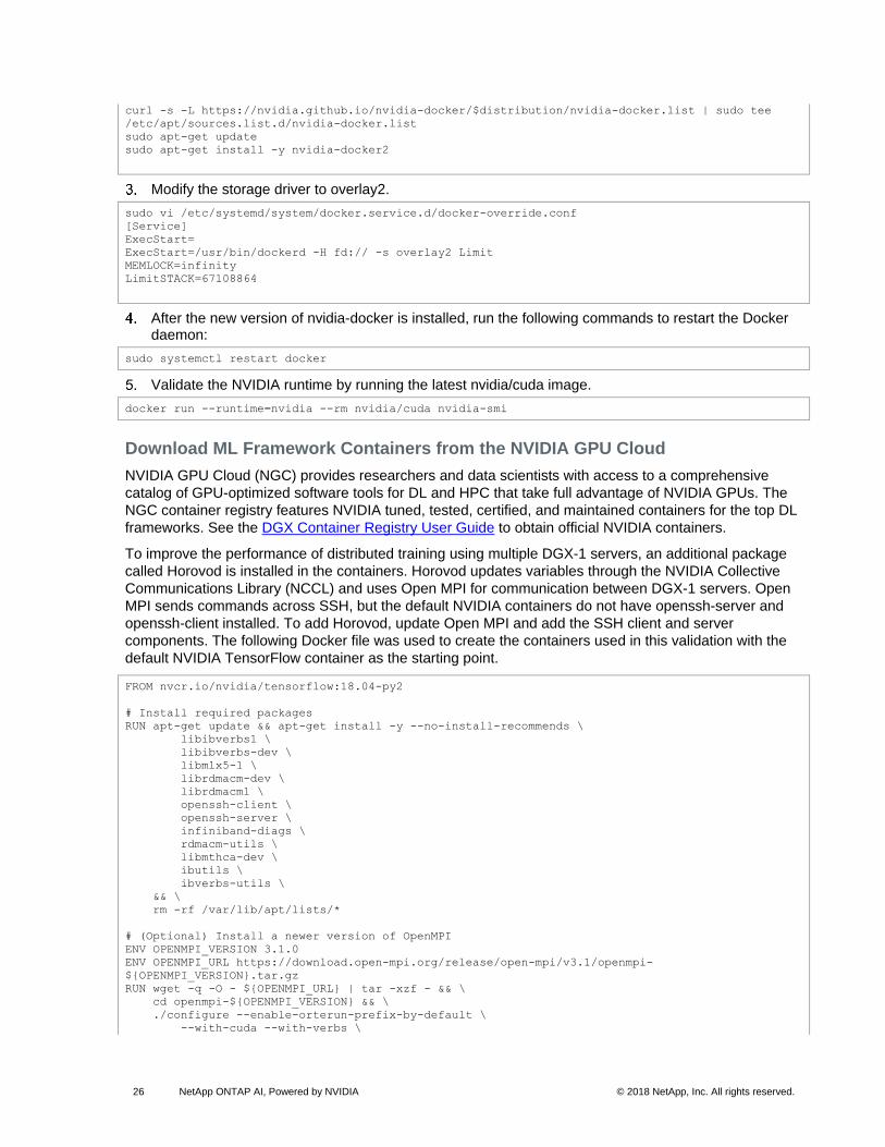
Modify the storage driver to overlay2.
sudo vi /etc/systemd/system/docker.service.d/docker-override.conf
[Service]
ExecStart=
ExecStart=/usr/bin/dockerd -H fd:// -s overlay2 Limit
MEMLOCK=infinity
LimitSTACK=67108864
After the new version of nvidia-docker is installed, run the following commands to restart the Docker daemon:
sudo systemctl restart docker
Validate the NVIDIA runtime by running the latest nvidia/cuda image.
docker run --runtime=nvidia --rm nvidia/cuda nvidia-smi
Download ML Framework Containers from the NVIDIA GPU Cloud
NVIDIA GPU Cloud (NGC) provides researchers and data scientists with access to a comprehensive
catalog of GPU-optimized software tools for DL and HPC that take full advantage of NVIDIA GPUs. The
NGC container registry features NVIDIA tuned, tested, certified, and maintained containers for the top DL
frameworks. See the DGX Container Registry User Guide to obtain official NVIDIA containers.
To improve the performance of distributed training using multiple DGX-1 servers, an additional package
called Horovod is installed in the containers. Horovod updates variables through the NVIDIA Collective
Communications Library (NCCL) and uses Open MPI for communication between DGX-1 servers. Open
MPI sends commands across SSH, but the default NVIDIA containers do not have openssh-server and
openssh-client installed. To add Horovod, update Open MPI and add the SSH client and server
components. The following Docker file was used to create the containers used in this validation with the
default NVIDIA TensorFlow container as the starting point.
FROM nvcr.io/nvidia/tensorflow:18.04-py2
# Install required packages
RUN apt-get update && apt-get install -y --no-install-recommends \
libibverbs1 \
libibverbs-dev \
libmlx5-1 \
librdmacm-dev \
librdmacm1 \
openssh-client \
openssh-server \
infiniband-diags \
rdmacm-utils \
libmthca-dev \
ibutils \
ibverbs-utils \
&& \
rm -rf /var/lib/apt/lists/*
# (Optional) Install a newer version of OpenMPI
ENV OPENMPI_VERSION 3.1.0
ENV OPENMPI_URL https://download.open-mpi.org/release/open-mpi/v3.1/openmpi-
${OPENMPI_VERSION}.tar.gz
RUN wget -q -O - ${OPENMPI_URL} | tar -xzf - && \
cd openmpi-${OPENMPI_VERSION} && \
./configure --enable-orterun-prefix-by-default \
--with-cuda --with-verbs \

27 NetApp ONTAP AI, Powered by NVIDIA © 2018 NetApp, Inc. All rights reserved.
--prefix=/usr/local/mpi --disable-getpwuid && \
make -j"$(nproc)" install && \
cd .. && rm -rf openmpi-${OPENMPI_VERSION}
ENV PATH /usr/local/mpi/bin:$PATH
# Create SSH authentication and Disable SSH host key checking
RUN mkdir -p /var/run/sshd && \
mkdir -p /root/.ssh && \
echo " StrictHostKeyChecking no" >> /etc/ssh/ssh_config && \
echo " UserKnownHostsFile /dev/null" >> /etc/ssh/ssh_config && \
echo " LogLevel quiet" >> /etc/ssh/ssh_config && \
mkdir -p /root/.ssh && \
echo "HOST *" > /root/.ssh/config && \
ssh-keygen -t rsa -b 4096 -f /root/.ssh/id_rsa -N "" && \
cp /root/.ssh/id_rsa.pub /root/.ssh/authorized_keys && \
chmod 700 /root/.ssh && \
chmod 600 /root/.ssh/*
# Update libraries
RUN ldconfig
6 Solution Verification
This section contains information about the tests used to verify that the infrastructure is installed and
configured correctly. Each of the tests in this section should be performed to make sure that the system
operates as expected.
6.1 Network Validation
Perform the following tests to make sure that the network is configured correctly for each of the traffic
types used.
RoCE Network Validation Test
This test verifies that the DGX-1 servers can communicate with each other using the RoCE network
connections.
Make sure that all 100Gb network interfaces have been configured by using the procedure in the section “Configure the 100GbE Interfaces,” earlier in this document.
Run the Mellanox bandwidth validation tool to perform I/O over each of the 100Gb Ethernet links used for RoCE communications:
a. Run the following command on one server:
ib_send_bw -d mlx5_0 -i 1 -S 3 -F --report_gbits
b. Run the following command on the second server:
ib_send_bw -d mlx5_0 -i 1 -S 3 -F --report_gbits 172.31.91.24
c. Make sure that an average bandwidth of over 95% is achieved.
--------------------------------------------------------------------------------
-------
Send BW Test
Dual-port : OFF Device : mlx5_0
Number of qps : 1 Transport type : IB
Connection type : RC Using SRQ : OFF
TX depth : 128
CQ Moderation : 100
Mtu : 4096[B]
Link type : Ethernet
GID index : 3
Max inline data : 0[B]
rdma_cm QPs : OFF
28 NetApp ONTAP AI, Powered by NVIDIA © 2018 NetApp, Inc. All rights reserved.
Data ex. method : Ethernet
--------------------------------------------------------------------------------
-------
local address: LID 0000 QPN 0x00d7 PSN 0x7a569d
GID: 00:00:00:00:00:00:00:00:00:00:255:255:172:31:91:23
remote address: LID 0000 QPN 0x01ca PSN 0x5578f6
GID: 00:00:00:00:00:00:00:00:00:00:255:255:172:31:91:24
--------------------------------------------------------------------------------
-------
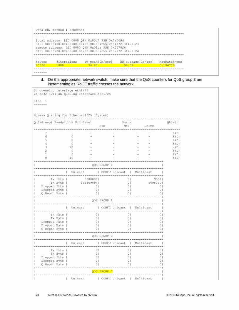
#bytes #iterations BW peak[Gb/sec] BW average[Gb/sec] MsgRate[Mpps]
65536 1000 96.89 96.88 0.184786
--------------------------------------------------------------------------------
-------
d. On the appropriate network switch, make sure that the QoS counters for QoS group 3 are incrementing as RoCE traffic crosses the network.
Sh queueing interface eth1/25
x6-3232-sw1# sh queuing interface eth1/25
slot 1
=======
Egress Queuing for Ethernet1/25 [System]
------------------------------------------------------------------------------
QoS-Group# Bandwidth% PrioLevel Shape QLimit
Min Max Units
------------------------------------------------------------------------------
7 - 1 - - - 6(D)
6 0 - - - - 6(D)
5 0 - - - - 6(D)
4 0 - - - - 6(D)
3 90 - - - - -(U)
2 0 - - - - 6(D)
1 0 - - - - 6(D)
0 10 - - - - 6(D)
+-------------------------------------------------------------------+
| QOS GROUP 0 |
+-------------------------------------------------------------------+
| | Unicast | OOBFC Unicast | Multicast |
+-------------------------------------------------------------------+
| Tx Pkts | 5380880| 0| 9531|
| Tx Byts | 393869894| 0| 5695330|
| Dropped Pkts | 0| 0| 0|
| Dropped Byts | 0| 0| 0|
| Q Depth Byts | 0| 0| 0|
+-------------------------------------------------------------------+
| QOS GROUP 1 |
+-------------------------------------------------------------------+
| | Unicast | OOBFC Unicast | Multicast |
+-------------------------------------------------------------------+
| Tx Pkts | 0| 0| 0|
| Tx Byts | 0| 0| 0|
| Dropped Pkts | 0| 0| 0|
| Dropped Byts | 0| 0| 0|
| Q Depth Byts | 0| 0| 0|
+-------------------------------------------------------------------+
| QOS GROUP 2 |
+-------------------------------------------------------------------+
| | Unicast | OOBFC Unicast | Multicast |
+-------------------------------------------------------------------+
| Tx Pkts | 0| 0| 0|
| Tx Byts | 0| 0| 0|
| Dropped Pkts | 0| 0| 0|
| Dropped Byts | 0| 0| 0|
| Q Depth Byts | 0| 0| 0|
+-------------------------------------------------------------------+
| QOS GROUP 3 |
+-------------------------------------------------------------------+
| | Unicast | OOBFC Unicast | Multicast |
29 NetApp ONTAP AI, Powered by NVIDIA © 2018 NetApp, Inc. All rights reserved.
+-------------------------------------------------------------------+
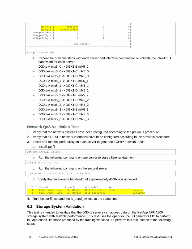
| Tx Pkts | 81936594| 0| 0|
| Tx Byts | 246652519884| 0| 0|
| Dropped Pkts | 0| 0| 0|
| Dropped Byts | 0| 0| 0|
| Q Depth Byts | 0| 0| 0|
+-------------------------------------------------------------------+
| QOS GROUP 4 |
+-------------------------------------------------------------------|
<output truncated>
e. Repeat the previous steps with each server and interface combination to validate the inter-GPU bandwidth for each server.
− DGX1-A mlx5_0 -> DGX1-B mlx5_0
− DGX1-A mlx5_0 -> DGX1-C mlx5_0
− DGX1-A mlx5_0 -> DGX1-D mlx5_0
− DGX1-A mlx5_1 -> DGX1-B mlx5_1
− DGX1-A mlx5_1 -> DGX1-C mlx5_1
− DGX1-A mlx5_1 -> DGX1-D mlx5_1
− DGX1-A mlx5_2 -> DGX1-B mlx5_2
− DGX1-A mlx5_2 -> DGX1-C mlx5_2
− DGX1-A mlx5_2 -> DGX1-D mlx5_2
− DGX1-A mlx5_3 -> DGX1-B mlx5_3
− DGX1-A mlx5_3 -> DGX1-C mlx5_3
− DGX1-A mlx5_3 -> DGX1-D mlx5_3
Network QoS Validation Test
Verify that the network switches have been configured according to the previous procedure.
Verify that all 100Gb network interfaces have been configured according to the previous procedure.
Install and run the iperf3 utility on each server to generate TCP/IP network traffic.
a. Install iperf3.
apt-get install iperf3
b. Run the following command on one server to start a listener daemon:
iperf3 -s -p 7501 -D
c. Run the following command on the second server:
iperf3 -c 172.31.94.23 -t 30 -l 1M -p 7501
d. Verify that an average bandwidth of approximately 45Gbps is achieved.
[ ID] Interval Transfer Bandwidth Retr
[ 4] 0.00-30.00 sec 161 GBytes 46.1 Gbits/sec 1956 sender
[ 4] 0.00-30.00 sec 161 GBytes 46.1 Gbits/sec receiver
Run the iperf3 test and the ib_send_bw test at the same time.
6.2 Storage System Validation
This test is intended to validate that the DGX-1 servers can access data on the NetApp AFF A800
storage system with suitable performance. This test uses the open-source I/O generator FIO to perform
I/O operations like those produced by the training workload. To perform this test, complete the following
steps.

30 NetApp ONTAP AI, Powered by NVIDIA © 2018 NetApp, Inc. All rights reserved.
Install FIO software on the DGX-1.
Apt-get install fio
Create an FIO job file called test.fio with the following contents:
[global]
rw=read
size=51200m
directory=/fgvolume #This should be set to a directory on the external storage NFS mount
bs=64k
[job1]
This file creates a single job that reads 50GB with a single thread performing 100% sequential reads at 64k block size to the directory specified. Additional information about FIO can be found in the FIO documentation.
On each DGX-1 server, run the following FIO command.
Fio test.fio
Run the same FIO command on all four servers simultaneously to validate concurrent bandwidth for each server.
The expected outcome of this test is storage bandwidth of roughly 1100MBps to 1200MBps per DGX-1
server as shown in the following output and 4GBps to 5GBps for all four DGX-1 servers combined.
root@wdl-dgx3:~# fio test.fio
job1: (g=0): rw=read, bs=64K-64K/64K-64K/64K-64K, ioengine=sync, iodepth=1
fio-2.2.10
Starting 1 process
job1: Laying out IO file(s) (1 file(s) / 51200MB)
Jobs: 1 (f=1): [R(1)] [100.0% done] [2003MB/0KB/0KB /s] [32.4K/0/0 iops] [eta 00m:00s]
job1: (groupid=0, jobs=1): err= 0: pid=29804: Thu Sep 6 07:53:08 2018
read : io=51200MB, bw=1944.3MB/s, iops=31108, runt= 26334msec
clat (usec): min=5, max=2614, avg=30.81, stdev=60.21
lat (usec): min=5, max=2614, avg=30.85, stdev=60.21
clat percentiles (usec):
| 1.00th=[ 5], 5.00th=[ 5], 10.00th=[ 6], 20.00th=[ 6],
| 30.00th=[ 10], 40.00th=[ 10], 50.00th=[ 11], 60.00th=[ 11],
| 70.00th=[ 18], 80.00th=[ 32], 90.00th=[ 65], 95.00th=[ 116],
| 99.00th=[ 306], 99.50th=[ 338], 99.90th=[ 386], 99.95th=[ 398],
| 99.99th=[ 1048]
bw (MB /s): min= 0, max= 2012, per=100.00%, avg=1962.81, stdev=277.60
lat (usec) : 10=28.50%, 20=44.52%, 50=13.40%, 100=8.17%, 250=2.47%
lat (usec) : 500=2.92%, 750=0.01%, 1000=0.01%
lat (msec) : 2=0.01%, 4=0.01%
cpu : usr=2.32%, sys=57.60%, ctx=94831, majf=0, minf=37
IO depths : 1=100.0%, 2=0.0%, 4=0.0%, 8=0.0%, 16=0.0%, 32=0.0%, >=64=0.0%
submit : 0=0.0%, 4=100.0%, 8=0.0%, 16=0.0%, 32=0.0%, 64=0.0%, >=64=0.0%
complete : 0=0.0%, 4=100.0%, 8=0.0%, 16=0.0%, 32=0.0%, 64=0.0%, >=64=0.0%
issued : total=r=819200/w=0/d=0, short=r=0/w=0/d=0, drop=r=0/w=0/d=0
latency : target=0, window=0, percentile=100.00%, depth=1
Run status group 0 (all jobs):
READ: io=51200MB, aggrb=1944.3MB/s, minb=1944.3MB/s, maxb=1944.3MB/s, mint=26334msec,
maxt=26334msec
Disk stats (read/write):
sdb: ios=203422/8, merge=0/1, ticks=30712/0, in_queue=30704, util=78.70%
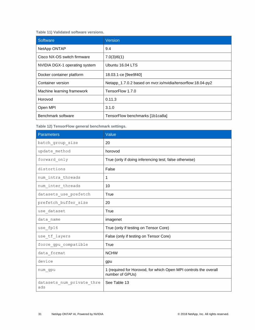
6.3 Basic TensorFlow Validation
This section describes how the solution was validated through four popular convolutional neural network
(CNN) models on TensorFlow. Table 11 describes the software versions that were used in this testing,
and Table 12 and Table 13 show the TensorFlow settings that were used.
31 NetApp ONTAP AI, Powered by NVIDIA © 2018 NetApp, Inc. All rights reserved.
Table 11) Validated software versions.
Software Version
NetApp ONTAP 9.4
Cisco NX-OS switch firmware 7.0(3)I6(1)
NVIDIA DGX-1 operating system Ubuntu 16.04 LTS
Docker container platform 18.03.1-ce [9ee9f40]
Container version Netapp_1.7.0.2 based on nvcr.io/nvidia/tensorflow:18.04-py2
Machine learning framework TensorFlow 1.7.0
Horovod 0.11.3
Open MPI 3.1.0
Benchmark software TensorFlow benchmarks [1b1ca8a]
Table 12) TensorFlow general benchmark settings.
Parameters Value
batch_group_size 20
update_method horovod
forward_only True (only if doing inferencing test; false otherwise)
distortions False
num_intra_threads 1
num_inter_threads 10
datasets_use_prefetch True
prefetch_buffer_size 20
use_dataset True
data_name imagenet
use_fp16 True (only if testing on Tensor Core)
use_tf_layers False (only if testing on Tensor Core)
force_gpu_compatible True
data_format NCHW
device gpu
num_gpu 1 (required for Horovod, for which Open MPI controls the overall number of GPUs)
datasets_num_private_thre
ads
See Table 13
32 NetApp ONTAP AI, Powered by NVIDIA © 2018 NetApp, Inc. All rights reserved.
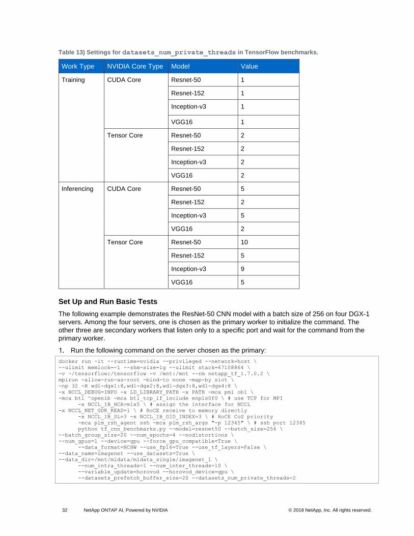
Table 13) Settings for datasets_num_private_threads in TensorFlow benchmarks.
Work Type NVIDIA Core Type Model Value
Training CUDA Core Resnet-50 1
Resnet-152 1
Inception-v3 1
VGG16 1
Tensor Core Resnet-50 2
Resnet-152 2
Inception-v3 2
VGG16 2
Inferencing CUDA Core Resnet-50 5
Resnet-152 2
Inception-v3 5
VGG16 2
Tensor Core Resnet-50 10
Resnet-152 5
Inception-v3 9
VGG16 5
Set Up and Run Basic Tests
The following example demonstrates the ResNet-50 CNN model with a batch size of 256 on four DGX-1
servers. Among the four servers, one is chosen as the primary worker to initialize the command. The
other three are secondary workers that listen only to a specific port and wait for the command from the
primary worker.
Run the following command on the server chosen as the primary:
docker run -it --runtime=nvidia --privileged --network=host \
--ulimit memlock=-1 --shm-size=1g --ulimit stack=67108864 \
-v ~/tensorflow:/tensorflow -v /mnt:/mnt --rm netapp_tf_1.7.0.2 \
mpirun -allow-run-as-root -bind-to none -map-by slot \
-np 32 -H wdl-dgx1:8,wdl-dgx2:8,wdl-dgx3:8,wdl-dgx4:8 \
-x NCCL_DEBUG=INFO -x LD_LIBRARY_PATH -x PATH -mca pml ob1 \
-mca btl ^openib -mca btl_tcp_if_include enp1s0f0 \ # use TCP for MPI
-x NCCL_IB_HCA=mlx5 \ # assign the interface for NCCL
-x NCCL_NET_GDR_READ=1 \ # RoCE receive to memory directly
-x NCCL_IB_SL=3 -x NCCL_IB_GID_INDEX=3 \ # RoCE CoS priority
-mca plm_rsh_agent ssh -mca plm_rsh_args "-p 12345" \ # ssh port 12345
python tf_cnn_benchmarks.py --model=resnet50 --batch_size=256 \
--batch_group_size=20 --num_epochs=4 --nodistortions \
--num_gpus=1 --device=gpu --force_gpu_compatible=True \
--data_format=NCHW --use_fp16=True --use_tf_layers=False \
--data_name=imagenet --use_datasets=True \
--data_dir=/mnt/mldata/mldata_single/imagenet_1 \
--num_intra_threads=1 --num_inter_threads=10 \
--variable_update=horovod --horovod_device=gpu \
--datasets_prefetch_buffer_size=20 --datasets_num_private_threads=2
33 NetApp ONTAP AI, Powered by NVIDIA © 2018 NetApp, Inc. All rights reserved.
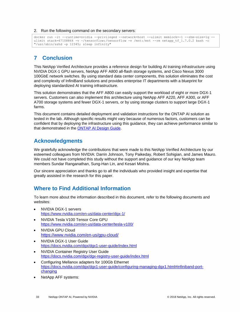
Run the following command on the secondary servers:
docker run -it --runtime=nvidia --privileged --network=host --ulimit memlock=-1 --shm-size=1g --
ulimit stack=67108864 -v ~/tensorflow:/tensorflow -v /mnt:/mnt --rm netapp_tf_1.7.0.2 bash -c
"/usr/sbin/sshd -p 12345; sleep infinity"
7 Conclusion
This NetApp Verified Architecture provides a reference design for building AI training infrastructure using
NVIDIA DGX-1 GPU servers, NetApp AFF A800 all-flash storage systems, and Cisco Nexus 3000
100GbE network switches. By using standard data center components, this solution eliminates the cost
and complexity of InfiniBand solutions and provides enterprise IT departments with a blueprint for
deploying standardized AI training infrastructure.
This solution demonstrates that the AFF A800 can easily support the workload of eight or more DGX-1
servers. Customers can also implement this architecture using NetApp AFF A220, AFF A300, or AFF
A700 storage systems and fewer DGX-1 servers, or by using storage clusters to support large DGX-1
farms.
This document contains detailed deployment and validation instructions for the ONTAP AI solution as
tested in the lab. Although specific results might vary because of numerous factors, customers can be
confident that by deploying the infrastructure using this guidance, they can achieve performance similar to
that demonstrated in the ONTAP AI Design Guide.
Acknowledgments
We gratefully acknowledge the contributions that were made to this NetApp Verified Architecture by our
esteemed colleagues from NVIDIA: Darrin Johnson, Tony Paikeday, Robert Sohigian, and James Mauro.
We could not have completed this study without the support and guidance of our key NetApp team
members Sundar Ranganathan, Sung-Han Lin, and Kesari Mishra.
Our sincere appreciation and thanks go to all the individuals who provided insight and expertise that
greatly assisted in the research for this paper.
Where to Find Additional Information
To learn more about the information described in this document, refer to the following documents and
websites:
• NVIDIA DGX-1 servers https://www.nvidia.com/en-us/data-center/dgx-1/
• NVIDIA Tesla V100 Tensor Core GPU https://www.nvidia.com/en-us/data-center/tesla-v100/
• NVIDIA GPU Cloud
https://www.nvidia.com/en-us/gpu-cloud/
• NVIDIA DGX-1 User Guide https://docs.nvidia.com/dgx/dgx1-user-guide/index.html
• NVIDIA Container Registry User Guide https://docs.nvidia.com/dgx/dgx-registry-user-guide/index.html
• Configuring Mellanox adapters for 100Gb Ethernet https://docs.nvidia.com/dgx/dgx1-user-guide/configuring-managing-dgx1.html#infiniband-port-changing
• NetApp AFF systems:
34 NetApp ONTAP AI, Powered by NVIDIA © 2018 NetApp, Inc. All rights reserved.
− AFF datasheet https://www.netapp.com/us/media/ds-3582.pdf
− NetApp Flash Advantage for AFF https://www.netapp.com/us/media/ds-3733.pdf
• ONTAP 9.x documentation http://mysupport.netapp.com/documentation/productlibrary/index.html?productID=62286
• NetApp FlexGroup technical report https://www.netapp.com/us/media/tr-4557.pdf
• NetApp AFF A800 installation instructions https://library.netapp.com/ecm/ecm_download_file/ECMLP2842669
• NetApp Interoperability Matrix Tool http://support.netapp.com/matrix
• Cisco Nexus networking:
− Cisco Nexus 3232C series switches https://www.cisco.com/c/en/us/products/switches/nexus-3232c-switch/index.html
− Cisco Nexus 3232C configuration guide https://www.cisco.com/c/en/us/support/switches/nexus-3000-series-switches/products-installation-and-configuration-guides-list.html
− Cisco Nexus 3232C hardware installation guide https://www.cisco.com/c/en/us/td/docs/switches/datacenter/nexus3000/hw/installation/guide/b_n3000_hardware_install_guide.html
− Cisco Nexus 3232C command-line reference https://www.cisco.com/c/en/us/support/switches/nexus-3000-series-switches/products-command-reference-list.html
• Machine learning framework:
− TensorFlow: An Open-Source Machine Learning Framework for Everyone https://www.tensorflow.org/
− Horovod: Uber’s Open-Source Distributed Deep Learning Framework for TensorFlow https://eng.uber.com/horovod/
− Enabling GPUs in the Container Runtime Ecosystem https://devblogs.nvidia.com/gpu-containers-runtime/
• Dataset and benchmarks:
− ImageNet http://www.image-net.org/
− TensorFlow benchmarks https://www.tensorflow.org/performance/benchmarks
− FIO disk I/O generator https://fio.readthedocs.io/en/latest/fio_doc.html
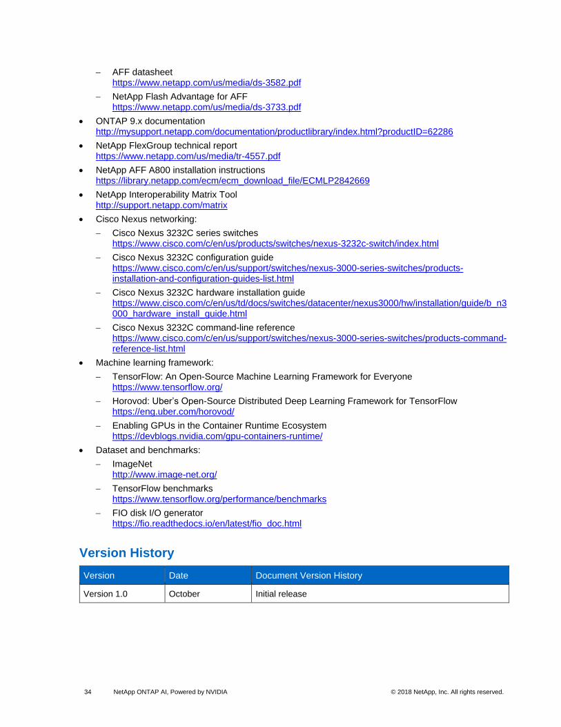
Version History
Version Date Document Version History
Version 1.0 October Initial release

35 NetApp ONTAP AI, Powered by NVIDIA © 2018 NetApp, Inc. All rights reserved.
Refer to the Interoperability Matrix Tool (IMT) on the NetApp Support site to validate that the exact product and feature versions described in this document are supported for your specific environment. The NetApp IMT defines the product components and versions that can be used to construct configurations that are supported by NetApp. Specific results depend on each customer’s installation in accordance with published specifications.
Copyright Information
Copyright © 2018 NetApp, Inc. and NVIDIA. All rights reserved. Printed in the U.S. No part of this document covered by copyright may be reproduced in any form or by any means—graphic, electronic, or mechanical, including photocopying, recording, taping, or storage in an electronic retrieval system—without prior written permission of the copyright owner.
Software derived from copyrighted NetApp material is subject to the following license and disclaimer:
THIS SOFTWARE IS PROVIDED BY NETAPP “AS IS” AND WITHOUT ANY EXPRESS OR IMPLIED WARRANTIES, INCLUDING, BUT NOT LIMITED TO, THE IMPLIED WARRANTIES OF MERCHANTABILITY AND FITNESS FOR A PARTICULAR PURPOSE, WHICH ARE HEREBY DISCLAIMED. IN NO EVENT SHALL NETAPP BE LIABLE FOR ANY DIRECT, INDIRECT, INCIDENTAL, SPECIAL, EXEMPLARY, OR CONSEQUENTIAL DAMAGES (INCLUDING, BUT NOT LIMITED TO, PROCUREMENT OF SUBSTITUTE GOODS OR SERVICES; LOSS OF USE, DATA, OR PROFITS; OR BUSINESS INTERRUPTION) HOWEVER CAUSED AND ON ANY THEORY OF LIABILITY, WHETHER IN CONTRACT, STRICT LIABILITY, OR TORT (INCLUDING NEGLIGENCE OR OTHERWISE) ARISING IN ANY WAY OUT OF THE USE OF THIS SOFTWARE, EVEN IF ADVISED OF THE POSSIBILITY OF SUCH DAMAGE.
NetApp reserves the right to change any products described herein at any time, and without notice. NetApp assumes no responsibility or liability arising from the use of products described herein, except as expressly agreed to in writing by NetApp. The use or purchase of this product does not convey a license under any patent rights, trademark rights, or any other intellectual property rights of NetApp.
The product described in this manual may be protected by one or more U.S. patents, foreign patents, or pending applications.
RESTRICTED RIGHTS LEGEND: Use, duplication, or disclosure by the government is subject to restrictions as set forth in subparagraph (c)(1)(ii) of the Rights in Technical Data and Computer Software clause at DFARS 252.277-7103 (October 1988) and FAR 52-227-19 (June 1987).
Trademark Information
NETAPP, the NETAPP logo, and the marks listed at http://www.netapp.com/TM are trademarks of NetApp, Inc. Other company and product names may be trademarks of their respective owners.