sc 8000 patient monitor - frank's hospital workshop€¦ · sc 8000 patient monitor service...
TRANSCRIPT
SC 8000 Patient MonitorService Manual
E331.E549U.719.10.01.02
ASK-T924-02-7600
EM G
uide
lines
, 199
7-04
-02


SC 8000 Patient Monitor Service Manual
ASKSC8
ADVISORY
Siemens is liable for the safety of its equipment only if maintenance, repair, and modifications are performed by authorized personnel, and if components affecting the equipment's safety are replaced with Siemens spare parts.
Any modification or repair not done by Siemens personnel must be documented. Such documentation must:
• be signed and dated
• contain the name of the company performing the work
• describe the changes made
• describe any equipment performance changes.
It is the responsibility of the user to contact Siemens to determine warranty status and/or liabilities if other than an authorized Siemens technician repairs or makes modifications to medical devices.
-T924-02-7600 Siemens Medical Systems, EM-PCS Danvers 000.SM.advisory.fm/06-99/kaupp

Service Manual SC 8000 Patient Monitor
Siemens Medical Systems, EM-PCS, Danvers ASK-T924-02-7600SC8000.SM.Advisory.fm/06-99/kaupp

SC 8000 Patient Monitor Service Manual
Table of Contents$'9,625<
7DEOHRI&RQWHQWVL
&KDSWHU*HQHUDO,QIRUPDWLRQ
2YHUYLHZ
,QWURGXFWLRQ
5HODWHG'RFXPHQWDWLRQ
&OHDQLQJ
7HFKQLFDO'DWD
%ULHI2SHUDWLQJ,QVWUXFWLRQV
6&0RQLWRU&RQWUROV
3HULSKHUDO'HYLFH&RQWUROV
3DVVZRUGV
&OLQLFDO3DVVZRUG
6HUYLFH3DVVZRUG
0HQXV
0DLQ0HQX
6HUYLFH0HQX
,QVWDOO0RQLWRULQJ6RIWZDUH
&RQILJXUDWLRQ'RZQORDG3URFHGXUH
'LDJQRVWLF/RJ8SORDG3URFHGXUH
&KDSWHU7KHRU\RI2SHUDWLRQ
,QWURGXFWLRQ
&RPSXWHU$UFKLFWHFWXUH
)LJXUH 6&%XV6WUXFWXUH
0DLQ3URFHVVRU%XV
)URQW(QG%XV
&200%XV
(UURU+DQGOLQJ
)LJXUH 6&%ORFN'LDJUDP
0DLQ8QLW
&RROLQJ6\VWHP
5HDO7LPH&ORFN
1RQYRODWLOH0HPRU\%DWWHU\%DFNXSDQG3RZHU5HVHW
03&&RPPXQLFDWLRQ&KDQQHOV
ASK-T924-02-7600 Siemens Medical Systems, EM-PCS Danvers i SC8000.fm/09-98/kaupp

Service Manual SC 8000 Patient Monitor
,QWHUIDFHV
/RFDO)L[HG.H\V,QWHUIDFH
5RWDU\.QRE,QWHUIDFH
)DVW$QDORJ2XWSXW
+L)L$XGLEOH$ODUP,QWHUIDFH
/('6WDWXV,QWHUIDFH
4566\QF2XW,QWHUIDFH
/RFDO$ODUP2XW,QWHUIDFH
5HFRUGHU,QWHUIDFH
6HULDO((35206
)LJXUH *UDSKLFV6XEV\VWHP
*UDSKLFV6XEV\VWHP
2YHUYLHZ
)XQFWLRQDO'HVFULSWLRQ
9LGHR2XWSXW
)LJXUH '636XEV\VWHP
'636XEV\VWHP
)LJXUH 32'&RPPXQLFDWLRQV
32'&206XEV\VWHP
2YHUYLHZ
)LJXUH 3RZHU&RQYHUVLRQ
2XWSXWV
(UURU+DQGOLQJ
3RZHU&RQYHUVLRQ
3RZHU&RQWURO
3RZHU%XVV
&RQWURODQG/RDG6HTXHQFLQJ
3RZHU2Q2II
3RZHU6RXUFH&RQWURO
%DWWHU\FKDUJLQJ
,QGLFDWRU/('V
7DEOH3RZHUDQG&KDUJHU/(',QGLFDWRUV
3RZHU0RGH,QGLFDWLRQ
7DEOH3RZHU0RGH7DEOH
3LH]R$ODUP
7DEOH3LH]R$ODUP
ii Siemens Medical Systems, EM-PCS, Danvers ASK-T924-02-7600SC8000.SM.fm/09-99/kaupp

SC 8000 Patient Monitor Service Manual
)DXOW3URWHFWLRQ
([WHUQDO3RG2YHUORDG3URWHFWLRQ
(OHFWULFDO6SHFLILFDWLRQV
3RZHU6XSSO\
%DWWHU\6SHFLILFDWLRQV
)URQW%H]HO
,QWURGXFWLRQ
)XQFWLRQDO'HVFULSWLRQ
/RFDO5RWDU\.QREIL[HG.H\V,QWHUIDFH
%DWWHU\SRZHU/(',QWHUIDFH
0XOWL0HG)URQW(QG
6DIHW\
)LJXUH 0XOWL0HG)URQW(QG
)XQFWLRQDO'HVFULSWLRQ
(&*5HVS
7DEOH3DUDPHWHU6DPSOLQJ7DEOH
)LJXUH /HDG)RUPLQJ1HWZRUN
)LJXUH 5HVSLUDWLRQ)XQFWLRQDO%ORFN'LDJUDP
)LJXUH 7HPSHUDWXUH)XQFWLRQDO%ORFN'LDJUDP
7HPSHUDWXUH
)LJXUH 6S2)XQFWLRQDO%ORFN'LDJUDP
6S2
)LJXUH 1%3)XQFWLRQDO%ORFN'LDJUDP
1%3
,QWURGXFWLRQ
3QHXPDWLF6XEDVVHPEO\
7UDQVGXFHUV
3QHXPDWLF&RQWUROV
6DIHW\WLPHU
/RJLFJDWHDUUD\
1RQYRODWLOHPHPRU\
+RVHGHWHFWLRQ
:DWFKGRJ7LPHU
)LJXUH +HPR0HG)URQW(QG
+HPR0HG)URQW(QG
,QWURGXFWLRQ
ASK-T924-02-7600 Siemens Medical Systems, EM-PCS Danvers iii SC8000.fm/09-98/kaupp

Service Manual SC 8000 Patient Monitor
3UHVVXUH
&DUGLDF2XWSXW
)LJXUH HW&26HQVLQJ3URFHVV)XQFWLRQDO%ORFN'LDJUDP
HW&23RG
6\VWHP0HPRU\
8VHU,QWHUIDFH
+(0232'
)XQFWLRQDO'HVFULSWLRQ
3UHVVXUH
)LJXUH +(0232')XQFWLRQDO%ORFN'LDJUDP
)LJXUH ,%3)XQFWLRQDO%ORFN'LDJUDP
7HPSHUDWXUH
&DUGLDF2XWSXW
((35206WRUDJH
/&'DQG3XVK%XWWRQV
&XUUHQW/LPLWLQJWKH9ROWDJH5HIHUHQFH
$GYDQFHG&RPP2SWLRQ
&RPP2SWLRQ%RDUG+DUGZDUH
((3520V
&KDSWHU5HSDLU
,QWURGXFWLRQ
5HSODFHDEOH,WHPV
)LJXUH %DVLF6&3DWLHQW0RQLWRU
5RWDU\.QRE
5HSODFLQJ)DQ
5HPRYLQJ)DQ
,QVWDOOLQJ)DQ
2SHQLQJ0RQLWRU
%DWWHU\DQG7UD\
5HPRYLQJ%DWWHU\
5HPRYLQJ7UD\
,QVWDOOLQJ%DWWHU\DQG7UD\
3RZHU6XSSO\
5HPRYLQJ3RZHU6XSSO\
,QVWDOOLQJ3RZHU6XSSO\
iv Siemens Medical Systems, EM-PCS, Danvers ASK-T924-02-7600SC8000.SM.fm/09-99/kaupp

SC 8000 Patient Monitor Service Manual
&RQQHFWRU,23&%RDUG
)UHHLQJ5HDU3DQHO,QWHUIDFH%RDUG
)UHHLQJ)URQW3DQHO,QWHUIDFH%RDUG
)LJXUH 1%33XPS6XEDVVHPEO\DQG6SHDNHU
5HLQVWDOOLQJ&RQQHFWRU,23&%6XEDVVHPEO\
0DLQ3URFHVVRU3&%6XEDVVHPEO\
5HPRYLQJ0DLQ3&%VXEDVVHPEO\
,QVWDOOLQJ0DLQ3URFHVVRU3&%6XEDVVHPEO\
6SHDNHU6XEDVVHPEO\
5HPRYLQJ6SHDNHU
,QVWDOOLQJ6SHDNHU
1%36XEDVVHPEO\
5HPRYLQJ1%36XEDVVHPEO\
,QVWDOOLQJ1%36XEDVVHPEO\
)LJXUH )URQW%H]HO6XEDVVHPEO\
)URQW%H]HO6XEDVVHPEO\
5HPRYLQJ)URQW%H]HO6XEDVVHPEO\
,QVWDOOLQJ)URQW%H]HO6XEDVVHPEO\
)LJXUH 2SWLFDO(QFRGHU6XEDVVHPEO\5HPRYDO5HSODFHPHQW
5HSODFLQJ2SWLFDO(QFRGHU6XEDVVHPEO\
)LJXUH 5HPRYLQJ)URQW%H]HO/DQJXDJH/DEHO
5HPRYLQJ,QVWDOOLQJ/DQJXDJH/DEHO
5HPRYLQJ([LVWLQJ/DEHO
,QVWDOOLQJ/DQJXDJH/DEHO
0,%2SWLRQDQG$GY&RPP2SWLRQ6XEDVVHPEOLHV
2SHQLQJ$GY&RPP2SWLRQ6XEDVVHPEO\
)LJXUH $GY&RPPDQG0,%2SWLRQVDQG5HDU3DQHO
)LJXUH &RPP2SWLRQ6XEDVVn\&RYHU5HPRYDO,QVWDOODWLRQ
)LJXUH 5HPRYLQJ,QVWDOOLQJ0,%2SWLRQ3&ERDUG
5HPRYLQJ0,%2SWLRQ
5HPRYLQJ$GY&RPP2SWLRQ6XEDVVHPEO\
)LJXUH 5HPRYLQJ,QVWDOOLQJ$GY&RPP2SWLRQ3&ERDUG
,QVWDOOLQJ$GY&RPP2SWLRQ6XEDVVHPEO\
,QVWDOOLQJ0,%2SWLRQ
&ORVLQJ$GY&RPP2SWLRQ6XEDVVHPEO\
&ORVLQJ0RQLWRU
ASK-T924-02-7600 Siemens Medical Systems, EM-PCS Danvers v SC8000.fm/09-98/kaupp

Service Manual SC 8000 Patient Monitor
&KDSWHU)XQFWLRQDO9HULILFDWLRQDQG&DOLEUDWLRQ
,QWURGXFWLRQ
5HFRPPHQGHG7RROVDQG7HVW(TXLSPHQW
7DEOH5HFRPPHQGHG7RROVDQG7HVW(TXLSPHQW
3RZHU&LUFXLWVDQG6WDUWXS
3RZHU212))
3RZHU8S6HTXHQFH
5RWDU\.QRE
/&''LVSOD\
)L[HG.H\V
212)).H\
0DLQ6FUHHQ.H\
$ODUP6LOHQFH.H\
$ODUP/LPLWV.H\
$OO$ODUPV2II.H\
&RGH.H\
5HFRUG.H\
3ULQW6FUHHQ.H\
1%36WDUW6WRS.H\
=RRP.H\
+HOS.H\
0DUN.H\
(&*5(63)XQFWLRQV
(&*5(637HVW6HWXS
:DYHIRUPV'LJLWDO5HDGRXWV7RQHV
3DFHU'HWHFWLRQ
/HDG2II,QGLFDWRUV
$ODUP)XQFWLRQ
$V\VWROH
6S2)XQFWLRQ
6S27HVW6HWXS
:DYHIRUPV'LJLWDO5HDGRXWV7RQHV
3XOVH7RQH*HQHUDWRU
6S2/LPLWV$ODUPV
7HPSHUDWXUH)XQFWLRQ
7HPSHUDWXUH7HVW6HWXS
vi Siemens Medical Systems, EM-PCS, Danvers ASK-T924-02-7600SC8000.SM.fm/09-99/kaupp

SC 8000 Patient Monitor Service Manual
'LJLWDO5HDGRXW
7HPSHUDWXUH&DOLEUDWLRQ&KHFN
7DEOH5HVLVWDQFH9DOXHYV7HPSHUDWXUH
5HFRPPHQGHG(TXLSPHQW
3URFHGXUH
1RQ,QYDVLYH%ORRG3UHVVXUH)XQFWLRQ
)LJXUH 1%3&DOLEUDWLRQ&KHFN&DOLEUDWLRQ7HVW6HWXS
6\VWHP6HWXSDQG3QHXPDWLFV/HDNDJH7HVW
&DOLEUDWLRQ&KHFN
1%3&DOLEUDWLRQ3URFHGXUH
1%3&KDUDFWHUL]DWLRQ
+DUGZDUH2YHUSUHVVXUH
3XPS
,QWHUYDO0RGH
6DIHW\7LPHU
HW&2)XQFWLRQ
)LJXUH ,%3)XQFWLRQDO9HULILFDWLRQ7HVW6HWXSIRU+HPR0HG3RG
+HPR0HG3RG
,%3)XQFWLRQ
,%37HVWVHWXS
&KDQQHO$
&KDQQHO%
&KDQQHO&
&KDQQHO'
)LJXUH ,%3)XQFWLRQDO9HULILFDWLRQ7HVW6HWXSIRU+(0232'V
&DUGLDF2XWSXW)XQFWLRQ
+(0232'
,%3)XQFWLRQ
,%37HVWVHWXS
+(0232'&KDQQHO$
+(0232'&KDQQHO%
+(0232'&KDQQHO&
+(0232'&KDQQHO'
7HPSHUDWXUH)XQFWLRQ
&DUGLDF2XWSXW)XQFWLRQ
0HPRU\%DFNXS
ASK-T924-02-7600 Siemens Medical Systems, EM-PCS Danvers vii SC8000.fm/09-98/kaupp

Service Manual SC 8000 Patient Monitor
0,%DQG&$12SWLRQVLILQVWDOOHG
$GY&RPP2SWLRQLILQVWDOOHG
&RQILJXUDWLRQ
%DWWHU\&KDUJHU&LUFXLW
5HFRUGHU)XQFWLRQ
/HDNDJH7HVWV
5HVLVWDQFH7HVW
)LJXUH /HDNDJH&XUUHQW7HVW6HWXSV
/HDNDJH&XUUHQW7HVWV
&KDSWHU7URXEOHVKRRWLQJ
,QWURGXFWLRQ
5HFRPPHQGHG7RROVDQG7HVW(TXLSPHQW
7DEOH5HFRPPHQGHG7RROVDQG7HVW(TXLSPHQW
3RZHU3UREOHPV
3RZHU3UREOHPV
1R5HVSRQVH:KHQ32:(5212)).H\3UHVVHG
7DEOH3RZHU2Q3UREOHPV
3RZHU2Q2II3LH]R7RQH)DLOVWR6RXQG
7DEOH3RZHURII$ODUP0DOIXQFWLRQ
3RZHU8S6HTXHQFH)DLOVWR&RPSOHWH3URSHUO\
7DEOH3RZHUXS3URFHVV0DOIXQFWLRQ
0RQLWRUIDLOVWRRSHDWHRQEDWWHU\SRZHU
5RWDU\.QRE0DOIXQFWLRQ
7DEOH3RZHUXS3URFHVV0DOIXQFWLRQ
7DEOH5RWDU\.QRE0DOIXQFWLRQ
)DQ0DOIXQFWLRQ
9*$'LVSOD\0DOIXQFWLRQ
)L[HG.H\)DLOVWR)XQFWLRQ
,VRODWLQJ&DEOH0DOIXQFWLRQV
7DEOH)DQ0DOIXQFWLRQ
7DEOH9*$'LVSOD\0DOIXQFWLRQ
7DEOH)L[HG.H\0DOIXQFWLRQ
9LVLEOHRU$XGLEOH$ODUP5HSRUWLQJ)DLOXUH
7DEOH$ODUP0DOIXQFWLRQV
0XOWL0HG32'3DUDPHWHU6LJQDO3UREOHPV
7DEOH3DUDPHWHU6LJQDO3UREOHPV
viii Siemens Medical Systems, EM-PCS, Danvers ASK-T924-02-7600SC8000.SM.fm/09-99/kaupp

SC 8000 Patient Monitor Service Manual
1%3
1%3(UURU0HVVDJHV
1%37URXEOHVKRRWLQJ
7DEOH1%30DOIXQFWLRQV
HW&20DOIXQFWLRQ
+(023RG+HPR0HG3RG
7DEOHHW&20DOIXQFWLRQV
5HDGLQJV0LVVLQJRU,QDFFXUDWH
,%30DOIXQFWLRQV
7DEOH,%30DOIXQFWLRQV
1R3ULQWRXWIURP5HFRUGHU
7DEOH5HFRUGHU3UREOHPV
3DWLHQW5HODWHG'DWD1RW5HWDLQHGRU0RQLWRU)DLOVWR&RPSXWH7UHQGV
6RIWZDUH/RDGLQJ3UREOHPV
'LIILFXOW\DFTXLULQJH[SRUWSURWRFROGDWD
7RWDORUSDUWLDOORVVRIQHWZRUNFRPPXQLFDWLRQV
3UREOHP5HSRUW
$SSHQGL[$5HSODFHPHQW3DUWV
)LJXUH$ %DVLF6&0RQLWRU7RS&RYHU5HPRYHG
7DEOH$%DVLF6&0RQLWRU5HSODFHDEOH3DUWV6XEDVVHPEOLHV
)LJXUH$ )URQW%H]HO6XEDVVHPEO\DQG7RS&RYHU
7DEOH$)URQW%H]HO6XEDVVn\DQG7RS&RYHU5HSODFHDEOH3DUWV6XEDVVHPEOLHV
)LJXUH$ $GY&RPPDQG0,%2SWLRQV
7DEOH$$GY&RPPDQG0,%2SWLRQV5HSODFHDEOH3DUWV6XEDVVHPEOLHV
$SSHQGL[%&RQQHFWRU&DEOH3LQRXWV
)LJXUH% )URQW3DQHO&RQQHFWRUVVKRZQIRU0RQLWRUZ≥9(VRIWZDUHLQVWDOOHG
)LJXUH% 5HDU3DQHO&RQQHFWRUVZR$GY&RPP2SWLRQLQVWDOOHG
)LJXUH% 5HDU3DQHO&RQQHFWRUVZ$GY&RPP2SWLRQ,QVWDOOHG
0XOWL0HG3RG&DEOH&RQQHFWRURQ6&
)LJXUH% 0XOWL0HG3RG&DEOH&RQQHFWRU
7DEOH%0XOWL0HG3RG&DEOH&RQQHFWRU3LQRXWV
+HPR0HG3RG&DEOH&RQQHFWRURQ6&
)LJXUH% +HPR0HG3RG&DEOH&RQQHFWRU
7DEOH%+HPR0HG3RG&DEOH&RQQHFWRU3LQRXWV
$X[&RQQHFWRURQ6&
)LJXUH% $X[$X[DQG$X[&RQQHFWRUVUHIHUWR7DEOH%
ASK-T924-02-7600 Siemens Medical Systems, EM-PCS Danvers ix SC8000.fm/09-98/kaupp
Service Manual SC 8000 Patient Monitor
6&1HWZRUN&RQQHFWRU
)LJXUH% 1HWZRUN&RQQHFWRU
7DEOH%$X[&RQQHFWRUV3LQRXWV
7DEOH%1HWZRUN&RQQHFWRU3LQRXWV
6&$QDORJ2XWSXW&RQQHFWRU
)LJXUH% $QDORJ2XWSXW&RQQHFWRUV)URQW5HDUUHIHUWR7DEOH%
7DEOH%$QDORJ2XWSXW&RQQHFWRUV3LQRXWV
0XOWL0HG3RG
)LJXUH% 0XOWL0HG3RG5HIHUWR7DEOH%
7DEOH%0XOWL0HG3RG&RQQHFWRU3LQRXWV
6&56.H\SDG,QSXW$ODUP2XW&RQQHFWRU
)LJXUH% 56.H\SDG,QSXW$ODUP2XW&RQQHFWRUVHH7DEOH%
7DEOH%56.H\SDG,QSXW$ODUP2XW&RQQHFWRU3LQRXWV
5HPRWH$ODUP&DEOH
)LJXUH% 5HPRWH$ODUP&DEOH8QWHUPLQDWHG5HIHUWR7DEOH%
7DEOH%5HPRWH$ODUP&DEOH&RQQHFWRU3LQRXWVDQG:LUH&RORU&RGH
$QDORJ&DEOH
)LJXUH% $QDORJ&DEOH8QWHUPLQDWHG5HIHUWR7DEOH%
7DEOH%$QDORJ&DEOH&RORU&RGH
&DUGLDF2XWSXW,QWHUPHGLDWH&DEOH:LULQJ'LDJUDP
)LJXUH% &DUGLDF2XWSXW,QWHUPHGLDWH&DEOH:LULQJ'LDJUDP
,QSXW&RQQHFWRURQHW&23RG
)LJXUH% ,QSXW&RQQHFWRURQHW&23RG5HIHUWR7DEOH%
7DEOH%HW&23RG,QSXW&RQQHFWRU3LQV
+(023RG
)LJXUH% +(023RG&RQQHFWRUV5HIHUWR7DEOH%
)LJXUH% 3UHVV$GDSWHU,QSXW5HIHUWR7DEOH%
7DEOH%+(023RG&RQQHFWRU6LJQDOV
7DEOH%35(66,QSXW&RQQHFWRU
$SSHQGL[&'LDJQRVWLF(UURU0HVVDJHV
2YHUYLHZRI'LDJQRVWLF0HVVDJHV
7DEOH&'LDJQRVWLF/RJ&RGHV
$SSHQGL[')XQFWLRQDO9HULILFDWLRQ&KHFNOLVW
&OLQLFDO6LWH5HSRUW
$SSHQGL[(6HUYLFH6HWXS,QVWUXFWLRQV
x Siemens Medical Systems, EM-PCS, Danvers ASK-T924-02-7600SC8000.SM.fm/09-99/kaupp
Chapter 1: General Information1 Overview Although similar to an SC 7000 or SC 9000XL monitor in user interface and
monitoring capabilities, the SC 8000 has been designed to support applications that require a larger screen display in place of “pick-and-go” functionality. It also differs in several other significant ways —
• It has no integral display but instead provides an output connector for a separate VGA Display.
• It is AC powered and has a built-in power supply.
• An internal battery maintains monitoring functions for up to 20 minutes in the event of temporary AC power loss. The battery does not, however, provide power to the VGA display.
• It is fan cooled instead of convection cooled.
• It has no etCO2 module capability, but instead uses an etCO2 pod.
• When equipped with Advanced Communication Option, it provides MGM and MIB support as well as up to 5 user-defined setups.
2 Introduction This Manual is intended to serve as a source of technical information for qualified personnel to use in servicing SC 8000 Monitors and associated peripheral devices. In light of the state-of-the-art technology used in the manufacture of Siemens' equipment, proprietary nature of the software, and specialized equipment required for replacement of most individual parts, Siemens policy is for SC 8000 monitors, and peripheral modules specifically related to the SC 8000, to be serviced to only the field-replaceable subassembly level. Replacement of components other than those listed in “Appendix A: Replacement Parts”, should be performed only at Siemens service depots.
3 Related Documentation
• User Guide for the installed software version
• Hardware and Software Installation instructions
• Service Setup Instructions
4 Cleaning Contact with chlorine bleach, Cidex, or body fluids does not damage or cause discoloration of an SC 8000. Clean Base Unit, pods, and cables using a 95% solution of isopropyl alcohol.
Note: Bac solution mars the finish of the monitor case.
5 Technical Data A complete set of technical data is given in the Operating Instructions (User Guide) for the installed software version.
6 Brief Operating Instructions
This section provides a brief overview of SC 8000 monitor controls to assist technical personnel in servicing and testing procedures. For detailed operating instructions and additional information, consult the monitor’s User Guide and supplements for the installed software version.
6.1 SC 8000 Monitor Controls
Control of all SC 8000 functions is via fixed keys that have tactile feedback, and a rotary knob for selecting from on-screen menus that appear on the separate VGA Display. Turning the rotary knob locates different menu items, and pressing the knob in selects the item. Depending on the item selected, pressing the knob in may either bring up another menu or initiate an action. “Ghosted” items cannot be selected.
ASK-T924-02-7600 Siemens Medical Systems, EM-PCS Danvers 1 SC8000.SM.c1.fm/06-99/kaupp

Service Manual SC 8000 Patient Monitor
7 Peripheral Device Controls
Individual cartridges, pods, and peripheral devices (such as the R50 recorder) also have fixed keys that control specific aspects of their operation. Refer to the monitor’s User Guide for specific key functions.
8 Passwords SC 8000 monitors have two kinds of basic password protection -- clinical password, and service password. Clinical and service passwords are entered via selections on a keypad that appears whenever a password-protected function is selected. To enter a password, turn the rotary knob to highlight a number and then press in on the knob to enter the number. When all numbers of the password have been entered, turn the knob to highlight “Accept,” and press in on the knob.
8.1 Clinical Password The clinical password is available to authorized supervisory personnel at the clinical site as well as to service personnel.
8.2 Service Password The service password is available to only authorized service personnel.
9 Menus
9.1 Main Menu The Main Menu uses a three column layout for menu navigation: Level 1 = main selection list, Level 2 = workspace A, and Level 3 = workspace B. Selecting any function category on Level 1 of the Main Menu brings up a list of selectable related functions and menus in Level 2. Selecting a function in Level 2 produces a similar result in Level 3.
Press MENU fixed-key to display MAIN screen with overlay of Main Menu.
9.2 Service Menu The Service Menu is accessed via the Monitor Options selection under the Monitor Setup function on the Main Menu. To access the Service menu and related functions, do the following:
1) Select Monitor Setup on Level 1, then select Biomed on Level 2, and then select Service on Level 3.
2) Input the service password (4712).
Note: In general, the Service Menu provides access to the following (may vary with software version):
• Language selection• Regulation• Alarm Sounds• Network control• Network Configuration• Line frequency setting• Restore factory defaults• Copy setups to card• Copy setups to monitor• Install Software• Locked Options• Waveform Simulator
9.3 Install Monitoring Software
Software and languages for SC 8000 Monitors are installed from a memory card via the monitor’s memory card reader. If the software loading process fails to complete properly, and/or the monitor sounds a steady tone (other than the Piezo), repeat the procedure. If the process fails a second time, either the card or the Monitor is defective. Troubleshoot and repair or replace as necessary.
2 Siemens Medical Systems, EM-PCS, Danvers ASK-T924-02-7600SC8000.SM.c1.fm/06-99/kaupp

SC 8000 Patient Monitor Service Manual
1) With Monitor switched off, insert and firmly seat PCMCIA card into memory card slot. Do NOT remove PCMCIA card until instructed to do so.
Note: The card can be seated in only one orientation because of keyed channels on the end of the card. If the card can not be easily seated, remove card, turn card over, reinsert, and firmly seat. Do NOT attempt to forceably seat the card.
2) Power Monitor ON to initiate download process.
Note: During the download process, the pick and go icon (running man) and the SIEMENS logo appear on the screen. The icon initially displays as green and changes to white. The logo toggles between green and white,and finally displays as green on a white background. The newly installed software version appears under the logo.
3) After a single alert tone sounds and a message regarding patient data loss appears, select “Continue” and then select YES for new patient.
4) Access Bedside Setup, and verify that settings of Language, Regulation, Alarm Sounds, Transport Brightness, and Line Frequency are approrpriate for customer site. Also, assure that Waveform Simulator is set to OFF.
5) Remove PCMCIA card.
6) For an initial installation of monitor into an INFINITY NETWORK, refer to procedure in Software Installation Instructions or Service Setup Instructions to set Network Mode and configure monitor. Then go to step 9. Otherwise, continue.
7) Affix new software version label (supplied) over existing software version label near right-hand bottom of memory card slot on rear panel.
8) Verify that monitor returns to MAIN screen, after timeout.
9) Recycle PCMCIA card when it is of no further use.
9.4 Configuration Download Procedure
The configuration download procedure should not to be confused with the monitor configuration procedure required for DirectNet functioning (see “Appendix E: Service Setup Instructions”). In general, the procedure is to completely set up one monitor and then transfer the setup to a Data Card. The configuration stored in the Data Card can then be used to setup other monitors.
1) With no Data Card inserted, adjust settings for monitor exactly as required by customer.
2) Review configuration with appropriate customer personnel before proceeding.
3) Press Menu key, and select Save/Restore → Save Setup.
4) Enter clinical password, 375, and select Accept.
5) Wait for message “New Setup Saved.”
6) Repeat steps 1 through 5 for optional setups as required, and select Rename Setup in Biomed menu to name each setup in accordance with site requirements.
7) With MAIN screen displayed on monitor, insert and firmly seat Data Card into memory slot.
ASK-T924-02-7600 Siemens Medical Systems, EM-PCS Danvers 3 SC8000.SM.c1.fm/06-99/kaupp

Service Manual SC 8000 Patient Monitor
Note: The card can be fully inserted in only one orientation, because of keyed channels on the end of the card, and can be damaged if forced into the slot. Insert the card firmly, but do NOT attempt to force the card. Be sure that Write Protect on the card is OFF.
8) Press Menu key, and select Monitor Setup → Biomed → Service.
9) Enter Service password, 4712, and select Accept.
10) Select More → “Copy Setups to Card.”
11) Select “Copy All.”
12) Wait for message “Memory Card Tansfer Complete.” Then press Main Screen key and remove Data Card from monitor.
13) Insert card into next monitor to be identically configured.
14) Press Menu key, and select Monitor Setup → Biomed → Service
15) Enter Service password, 4712, and select Accept.
16) Select More → “Copy Setups to Monitor.”
17) Wait for message “Memory Card Tansfer Complete.” Then press Main Screen key and remove Data Card from monitor.
18) Press Menu key, and select Save/Restore → Restore Setup.
19) Select “Default” → “Patient and Monitor Settings.”
20) Repeat steps 13 through 19 until all monitors to be identically configured have been set up.
9.5 Diagnostic Log Upload Procedure
The monitor is constantly checking its performance during monitoring. If errors occur, they are logged in the unit and stored in non-volatile memory. The logs are useful in diagnosing problems remotely at the factory. The following procedure can upload the diagnostic logs from approximately 10 to 16 monitors to a Data Card, depending on the size of the individual logs. Assure that Write/Protect switch on Data Card is set to Write position.
1) With MAIN screen displayed on monitor, insert and firmly seat Data Card into memory slot.
2) Press Menu key, and select Monitor Setup → Biomed → Logs
3) Select “Copy All Logs.”
4) Remove Data Card from monitor, and repeat steps 1, 2 and 3 for next monitor from which logs are to be uploaded.
5) After all required diagnostic logs have been uploaded to the Data Card, send the Card (in its preaddressed return case when possible) to:
Siemens Medical Systems, Inc.
EM-PCS
16 Electronics Avenue
Danvers, MA 01923 U.S.A.
Att: SC 8000 Project Manager
Note: The battery in the Data Card must be recharged for a period of 12 hours approximately every six months. Any SC 8000 or SC 7000/9000XL Monitor powered by a CPS, IDS, or PSL can be used to recharge the Data Card. Insert the card into the Monitor, and allow it to remain in the monitor for 12 hours.
4 Siemens Medical Systems, EM-PCS, Danvers ASK-T924-02-7600SC8000.SM.c1.fm/06-99/kaupp

Chapter 2: Theory of Operation1 Introduction The SC 8000 is a high-end single-board patient monitor. The board
provides the following parameters; 6 lead ECG, Respiration, two Temperatures, SpO2, NBP, four IBPs, Cardiac Output, and two onboard 5 watt patient isolated ports for additional parameters. It has connectors for external CRT, user interface, audio, NBP pneumatic assembly, chart recorder, analog out, defib sync, memory card, and Uarts. The board also contains the patient isolated front ends.
2 Computer Archictecture
Hardware architecture of the monitors is based on a dual processor design using two Motorola MPC860s with onboard cache. The main processor is responsible for graphics and communications, while the second processor is dedicated to data acquisition and algorithm processing. A DSP subsystem preprocesses the front end data.
There are three major bus structures within the system; MAIN processor bus, FRONT END bus, and REMOTE COMM bus (see Figure 2-1). The buses operate at different speeds and efficiency. The FRONT END bus and REMOTE COMM bus have multiple bus masters and common memory to allow exchange between I/O devices.
The REMOTE COMM bus interfaces to the Advanced Comm Option. This option includes the main circuit board from the IDS.
Figure 2-1 SC 8000 Bus Structure
2.1 Main Processor Bus The Main processor bus is a 32 bit data bus connecting the MPC860 to its main bank of 16 meg DRAM memory. The Program for the monitor is stored in 8 meg Flash memory and uploaded to DRAM during initialization. The DRAM is optimized for multiple word transfers allowing efficient cache fills. This bus has an optional daughter card connector allowing expansion of the main memory space. The graphics controller is connected to this bus to allow high bandwidth access to video memory. The bus has a max bandwidth of 40 megbytes/sec.
86050MHz Processor
Local MemoryMemory
ExpansionGraphics I/O
86050MHz Processor
Common Memory DSP Pod I/O
Processor Bridge
Comm.Transmitter
Comm.Receiver
Common
MemoryProcessor
Network
Adapter
48
Megabytes/sec
3
Megabytes/sec
16
32
32
&200 %86
FRONT END BUS
MAIN BUS
48 Megabytes/sec
ASK-T924-02-7600 Siemens Medical Systems, EM-PCS Danvers 5 SC8000.SM.c2.fm/06-99/kaupp
Service Manual SC 8000 Patient Monitor
This bus also has an I/O space implemented in an FPGA. These functions include audio, chart recorder interface, keypad and rotary knob interface, and EEPROM. The EEPROM contains serial #’s, calibration constants and configurations. The I/O space also includes the Bridge to the FRONT END bus and a port to the REMOTE COMM bus. The Bridge to the FRONT END bus is unidirectional. This means that the Main processor may read and write to the FRONT END bus, but the Front end processor can not access the MAIN bus.
2.2 Front End Bus The Front End bus is a 32 bit data bus connecting the second MPC860 to its main bank of 4 meg DRAM memory. The program for this processor is downloaded from the main processor during initialization. The DRAM is optimized for multiple word transfers allowing efficient cache fills. Both processors contain 512K of battery-backed SRAM for trend and other patient data storage. Data is exchanged through the common memory. This bus has multiple bus masters that include the following:
• Front End 860
• Main 860
• DSP DMA
• POD Comm DMA (a POD is a configured front end)
• DRAM Refresh
2.3 COMM Bus The COMM bus interfaces to a network controller and other local serial buses including MIB, lGraphics, Gas Monitoring, and other peripherals. The host is stalled until completion of all read operations, but is released after a write is latched to be serialized.
2.4 Error Handling The hardware provides several circuits for error detection, error recovery, and safety. The main processor bus, front end processor bus, and COMM bus both have timeouts implemented with the arbiter to prevent a lock up of the system. The main 860 and the Front End 860 are both protected with watchdog timers. If a timer expires, the system initiates a reset and restarts the monitor.
The power supply is also monitored with a piezo alarm that sounds during power up (for test) and power down. This is to alert the user that the monitor has turned off. The piezo is also sounded continuously if the monitor does not reset properly after a watchdog timer has expired and the computer has halted.
6 Siemens Medical Systems, EM-PCS, Danvers ASK-T924-02-7600SC8000.SM.c2.fm/06-99/kaupp
SC 8000 Patient Monitor Service Manual
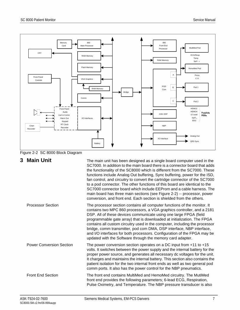
Figure 2-2 SC 8000 Block Diagram
3 Main Unit The main unit has been designed as a single board computer used in the SC7000. In addition to the main board there is a connector board that adds the functionality of the SC8000 which is different from the SC7000. These functions include Analog Out buffering, Sync buffering, power for the ISD, fan control, and circuitry to convert the cartridge connector of the SC7000 to a pod connector. The other functions of this board are identical to the SC7000 connector board which include EEProm and a cable harness. The main board has three main sections (see Figure 2-2) -- processor, power conversion, and front end. Each section is shielded from the others.
Processor Section The processor section contains all computer functions of the monitor. It contains two MPC 860 processors, a VGA graphics controller, and a 2181 DSP. All of these devices communicate using one large FPGA (field programmable gate array) that is downloaded at initialization. The FPGA contains all custom circuitry used in the computer, including the processor bridge, comm transmitter, pod com DMA, DSP interface, NBP interface, and I/O interfaces for both processors. Configuration of the FPGA may be updated with the Software through the memory card adapter.
Power Conversion Section The power conversion section operates on a DC input from +11 to +15 volts. It switches between the power supply and the internal battery for the proper power source, and generates all necessary dc voltages for the unit. It charges and maintains the internal battery. This section also contains the patient isolation for the two internal front ends as well as two general pod comm ports. It also has the power control for the NBP pneumatics.
Front End Section The front end contains MultiMed and HemoMed circuitry. The MutiMed front end provides the following parameters; 6-lead ECG, Respiration, Pulse Oximetry, and Temperature. The NBP pressure transducer is also
Memory
Card
Battery
I/O Interfaces
Comm
RAM Memory
VGA Graphics
Flash Memory
RAM Memory
860
Main Processor
Front Panel
Controls
Front Panel
Audio
Uart & Comm
Alarm Out
Keypad
RT Clock
RecorderChart
Recorder
860
Front End
Processor
Pod 2
Pod 1
HemoMed Pod
MultiMed Pod
I/O Interface
NBP
2181 DSP
POD
Com
RAM Memory
Bridge
Analog Out
QRS Sync
ECG/Resp
Temp
SpO 2
HEMO2
HEMO4
12 Lead
tcpO 2
A
B
C
Press
C.O.
CRT
3RVVLEOH
32'V
EEG
ASK-T924-02-7600 Siemens Medical Systems, EM-PCS Danvers 7 SC8000.SM.c2.fm/06-99/kaupp

Service Manual SC 8000 Patient Monitor
contained in this front end. The front end is based on a single 16 bit oversampling converter. Oversampling allows for a reduction in anti-aliasing analog circuitry while maintaining superior noise rejection. The HemoMed front end provides four invasive pressures and Thermal Dilution Cardiac Output.
3.1 Cooling System The cooling system for the main monitor uses a fan mounted on the rear of the chassis. If the internal temperature of the circuit board exceeds 80° C the monitor shuts down to prevent damage to the electronics. The monitor does not restart until the temperature is below the shut off value.
3.2 Real Time Clock The Real Time Clock function is implemented with the EPSON-SEIKO RTC4513 device, and is synchronized by the Central Station.
3.3 Non-volatile Memory Battery Backup and Power Reset
The shared RAM and real time clock are provided with a lithium battery backup circuit to prevent corruption of this non-volatile memory during a power loss condition (both primary and battery power are lost). Note that the battery used for non-volatile memory backup should not be confused with the internal and external batteries used to provide power to the monitor base unit when primary power is lost. Non-volatile memory lithium battery backup is controlled by a power supervisory device that provides a power reset during a power loss condition.
Note: No provisions have been made to recharge non-volatile memory backup battery. Eventually (≈10 years), battery must be replaced.
3.4 MPC 860 Communication Channels
MPC 860 has an embedded communications processor capable of executing several protocols such as UART or Ethernet. The 860 communications channels are used as follows:
Main Processor SCC1 Ethernet 10 Mbits/sec (future option)
SCC2 SC 9015 UART selectable baud
SCC3 MVP-1 UART selectable baud
SCC4 MVP-2 UART selectable baud
SMC1 main diag UART 19.2 Kbaud
SPI a/d (power monitor)
Front End Processor SCC3 serial pod data
SCC4 serial pod data
SMC1 front end diag UART
An additional UART implemented in the FPGA contains a large FIFO and interfaces to the chart recorder.
3.5 Interfaces3.5.1 Local Fixed Keys Interface The monitor base unit has twelve fixed function keys and a fixed key
dedicated as a power on/off switch. The power on/off switch is unique in that it is not directly available via a status read command, but rather is input to the power supply subsystem interface, where the switch state is detected and processed. Detection of a power off condition causes an interrupt to the host processor.
3.5.2 Rotary Knob Interface The rotary knob is a 16 detent rotary knob. Each detent position indicates a "click" clockwise or counter-clockwise. The change in detent position is detected via a 2 bit quadrature code that changes value every time the rotary knob is moved into a detent position. Also included in the rotary knob is a push button switch that is operated by a press/release action. This switch is used to select menu items on the screen.
8 Siemens Medical Systems, EM-PCS, Danvers ASK-T924-02-7600SC8000.SM.c2.fm/06-99/kaupp

SC 8000 Patient Monitor Service Manual
3.5.3 Fast Analog Output The ANALOG OUT interface consists of two identical channels. Each ANALOG OUT channel provides a 12 bit D/A function. The design uses a dual DAC to produce the D/A conversion. The sampled analog data is then passed through a 2 pole low pass filter. The analog output has a maximum delay of 20ms, and can be used for a defibrillator or balloon pump.
Separate Pacer Spike generation circuits for analog outputs 1 and 2 are provided.
3.5.4 HiFi Audible Alarm Interface The Audible alarm interface consists of an FM synthesis and Audio DAC chip set. There is also power amplifier drive circuitry for the two speaker interfaces: the internal speaker located in the base unit and the speaker located in the remote CRT. Circuitry has been included to provide a mechanism for automatically generating an error tone when a watchdog failure occurs via the piezo alarm Section 7.1.8).
The chip is loaded with tone frequency, pitch, harmonics, and volume information by the host processor, which controls the duration of the tone. The audio DAC converts the received sampled tone data and produces a sampled analog representation of the tone data.
The local speaker interface (also designated as main speaker interface) is designed for an 8 ohm speaker load. This local speaker interface produces 1 watt of power into an 8 ohm load, and has thermal shutdown capability.
The remote speaker interface is designed to produce a 1Vrms maximum signal into a 1 kohm load, and provides an ac coupled output.
3.5.5 LED/Status Interface Five LEDs provide information in the present SC 8000 configuration. Two are dedicated to the front end processor, to the DSP, and two to the main processor.
3.5.6 QRS Sync Out Interface A QRS sync output is provided. The QRS SYNC OUTPUT is an open collector type output driver that is pulled up to +12 volts (active HIGH). The output is initialized to Gnd on reset or power on.
This QRS signal is available via an external connector mounted on the main PC board. High level = +6V min (10KΩ load), +12.6V (no load); Low level (no QRS) = 1V @ 5ma.
3.5.7 Local Alarm Out Interface A Local Alarm output is provided. This Local Alarm Output is an open collector type output driver that is pulled up to +12 volts. The output is initialized to ground (0 volts) on reset or power on (active HIGH).
Loopback status is available via a status read command.
The Local Alarm Out signal is available via an external connector mounted on the main PC board.
3.6 Recorder Interface The recorder interface provides all of the necessary control, data and power supply signals required to drive an external recorder. The interface consists of current limited DC power and a UART with handshake signals. The UART is implemented in the main processor FPGA to allow for an extended FIFO.
3.7 Serial EEPROMS Four serial EEPROM devices, which contain the Monitor serial number, Ethernet address, NBP pneumatic characterization and calibration constants, and monitor setups, are located on the connector I/O board. If the main processor board is replaced the monitor will keep its set ups from these serial EEPROMs.
ASK-T924-02-7600 Siemens Medical Systems, EM-PCS Danvers 9 SC8000.SM.c2.fm/06-99/kaupp
Service Manual SC 8000 Patient Monitor
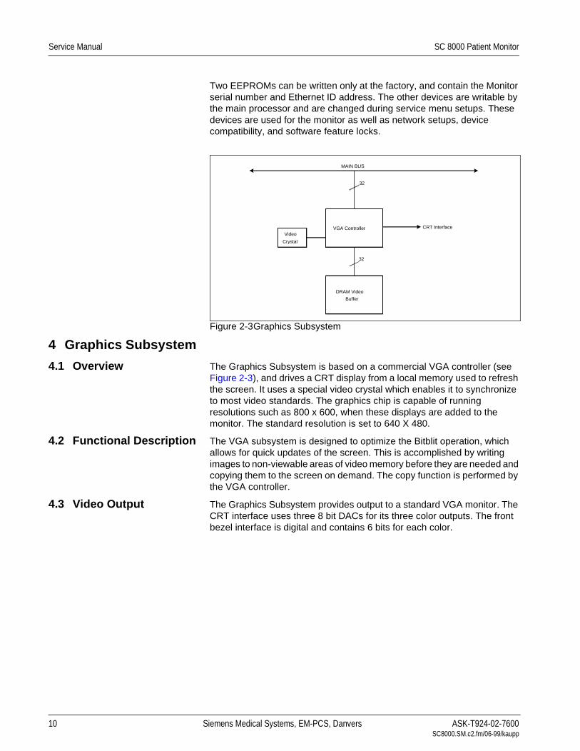
Two EEPROMs can be written only at the factory, and contain the Monitor serial number and Ethernet ID address. The other devices are writable by the main processor and are changed during service menu setups. These devices are used for the monitor as well as network setups, device compatibility, and software feature locks.
Figure 2-3Graphics Subsystem
4 Graphics Subsystem
4.1 Overview The Graphics Subsystem is based on a commercial VGA controller (see Figure 2-3), and drives a CRT display from a local memory used to refresh the screen. It uses a special video crystal which enables it to synchronize to most video standards. The graphics chip is capable of running resolutions such as 800 x 600, when these displays are added to the monitor. The standard resolution is set to 640 X 480.
4.2 Functional Description The VGA subsystem is designed to optimize the Bitblit operation, which allows for quick updates of the screen. This is accomplished by writing images to non-viewable areas of video memory before they are needed and copying them to the screen on demand. The copy function is performed by the VGA controller.
4.3 Video Output The Graphics Subsystem provides output to a standard VGA monitor. The CRT interface uses three 8 bit DACs for its three color outputs. The front bezel interface is digital and contains 6 bits for each color.
VGA Controller CRT Interface
MAIN BUS
DRAM Video
Buffer
Video
Crystal
32
32
10 Siemens Medical Systems, EM-PCS, Danvers ASK-T924-02-7600SC8000.SM.c2.fm/06-99/kaupp

SC 8000 Patient Monitor Service Manual
Figure 2-4 DSP Subsystem
5 DSP Subsystem The monitor uses a DSP for preprocessing of oversampled data (see Figure 2-4). The DSP is a specialized microprocessor that executes high speed repetitive functions such as digital filters. The DSP acquires data from the incoming serial pod comm data streams. The data sent to the DSP is selected by the control words in the pod com memory buffer. Typically only high acquisition rate data is sent to the DSP.
The DSP has two other communication ports both of which can access the internal 32Kword memory. The IDMA port is used to DMA data to and from the common memory. Bus sizing logic converts the DSP 16 bit port to the 32 bit FRONT END bus. During initialization this path is used to download code to the DSP. The main processor takes control of the DMA port during this time. Once the system is operational the DSP takes control of the DMA controller by using its I/O port. The I/O port is a dedicated 8 bit path into the main FPGA, which allows the DSP access to the DSP DMA controller as well as other internal FPGA registers, including analog out and QRS sync.
Bus
Sizing
DSP
Engine
32 Kwords
SRAM
IDMA
Port
I/O
Port
Serial
Ports
2181 DSP
DSP DMA
ControllerMUX
Main Processor
(Download)
Front End
Processor
8
32 16
Main FPGA
Memory
Address
Control
32
Front
End
Bus
Pod Com C & D
Pod Com A & B
ASK-T924-02-7600 Siemens Medical Systems, EM-PCS Danvers 11 SC8000.SM.c2.fm/06-99/kaupp

Service Manual SC 8000 Patient Monitor
Figure 2-5 POD Communications
6 POD COM Subsystem
A pod is a front end device that acquires data for a particular set of parameters. A pod may contain a processor and return preprocessed data or it may provide raw A/D samples.
Refer to Figure 2-5.
6.1 Overview Data acquisition of the monitor is controlled by several DMA controllers that operate on circular buffers residing in common memory on the FRONT END bus. There are four channels, each allocated a 16 bit transmit buffer and a 16 bit receive buffer. It takes four 32 bit transfers to update one location in every buffer, since each access consists of high and low data from different channels. The transmit buffer tells the pod either what sample to take or to change a control setting. The receive buffer contains a/d samples and status information from the pod. A control register in the FPGA sets a mux to the DSP’s communication port and connects the selected pod com channel.
Front
End
Bus
Channel A
Data In
Data Out
Channel D
Data In
Data Out
Channel C
Data In
Data Out
Channel B
Data In
Data Out
Memory Buffers
Common RAM
32
DMA
Channel A
Pod
Com
DMA
Channel B
Pod
Com
DMA
Channel C
Pod
Com
DMA
Channel D
Pod
Com
M
U
X
M
U
X
32
32
16
1616
16
16
DSP
Serial
CH A & B
DSP
Serial
CH C & D
M
U
X
64K Samples/sec
64K Samples/sec
64K Samples/sec
64K Samples/sec
64K Samples/sec
64K Samples/sec
64K Samples/sec
64K Samples/sec
Pod Com
Isolation
Pod Com
Isolation
Pod Com
Isolation
Pod Com
Isolation
Cartridge
Interface
MultiMed
Front End
HemoMed
Front End
etCO2Cartridge
Pod 1
Pod 2
(16 bit Samples)
Main FPGA
12 Siemens Medical Systems, EM-PCS, Danvers ASK-T924-02-7600SC8000.SM.c2.fm/06-99/kaupp

SC 8000 Patient Monitor Service Manual
Figure 2-6 Power Conversion
6.2 Outputs The pod com subsystem has four channels. Channel 1 is dedicated to the two internal front ends; the MultiMed and HemoMed. Channel 2 is dedicated to the slot on front for etCO2. This connector does not require patient isolation and has higher power than the pod com connectors. Channels 3 and 4 are both used to communicate with external pods. They have full patient isolation for both power and data.
6.3 Error Handling The pod com channels provide error detection by performing CRC checks on data in both directions. CRC errors are reported to the front end processor through interrupts.
7 Power Conversion Refer to Figure 2-6.
7.1 Power Control7.1.1 Power Buss Most monitor loads are powered from a DC power buss, called VBUSS,
within the monitor. VBUSS powers the +3.3VDC, +5.0VDC, ±12VDC, +40VDC and charger power converters. VBUSS also powers the external pods, cartridge, strip recorder and backlight. The NBP pump and valves as well as the internal multimed and hemomed front ends are powered from the regulated +12V supply.
7.1.2 Control and Load Sequencing
The switching of the VBUSS power inputs and the power converters is managed by the power supply gate array. This gate array controls the power on and power off of the monitor, and the battery charging process. It
PowerSupply
Battery
Power
Conversion
ASIC
MUXEnable
Switches
+3.3V
+5.0V
±12V
+40V
Battery
Charger
Pod Com
Backlight
Recorder
Battery
Computer
Section
+12VDC
+40V
V Buss
Status ControlOn/OffMain Processor
NBP Valves
NBP Pump
HemoMed
Power
MultiMed
Power
ASK-T924-02-7600 Siemens Medical Systems, EM-PCS Danvers 13 SC8000.SM.c2.fm/06-99/kaupp

Service Manual SC 8000 Patient Monitor
also provides a safety timer for the NBP pneumatics, which are controlled by the main processor FPGA.
Logic circuits on the main gate array sequence the power to the Pods, Cartridges, and Recorder to reduce power on load transients.
7.1.3 Power On / Off The monitor is normally switched on by the user pushing the On/Off button for at least 1 second. (The monitor may switch on when the switch is pushed for as short a time as 50 msec.)
The power down sequence may be initiated either by the user pushing the on/off switch for at least 1 second or when the batteries are depleted. When the power down sequence is initiated, the power conversion board control logic generates an interrupt for the processor. 100 ms later, the power supply shuts down. An immediate shutdown is initiated if a power fault occurs (such as overvoltage).
7.1.4 Power Source Control Power for the monitor is provided by the internal power supply or internal battery.
This input is monitored by a voltage comparator to determine that adequate voltage is present for internal power supply operation. The main battery also has a voltage comparator indicating that its voltage is high enough to provide power.
Based on the information provided by the comparators, a power source is connected to VBUSS in the priority of main power supply and then battery.
7.1.5 Battery charging The battery charger is a two-level constant voltage charger with a fixed current limit and temperature compensated voltage levels. When the main power comes on, the battery is fast charged at the high voltage until the current drops below a specific threshold. Then the charger voltage drops to the lower “float” voltage.
7.1.6 Indicator LEDs Two green LED indicators on the front bezel of the monitor indicate power and charger status, as given in Table 2-1.
7.1.7 Power Mode Indication The source of power is indicated to the processor via the power mode bits, as given in Table 2-2.
Table 2-1 Power and Charger LED Indicators
LED CONDITION LED STATE
Power Processor power on on
processor power off off
Charger Main power on on
Main power off off
*Battery or power fault off
* The charger LED is off if the battery temperature is exces-sive or if there is a power fault.
Table 2-2 Power Mode Table
MODE1 MODE0 INDICATION
1 X operating on main power
0 1 operating on battery
14 Siemens Medical Systems, EM-PCS, Danvers ASK-T924-02-7600SC8000.SM.c2.fm/06-99/kaupp

SC 8000 Patient Monitor Service Manual
7.1.8 Piezo Alarm The piezo alarm activates at power up, power down, and if a software watchdog is activated. At turn on, the software shuts the piezo off after two seconds. The piezo functions are as indicated in Table 2-3.
7.1.9 Fault Protection Reverse polarity protection for the battery and the main power input are provided by shunt diodes and fuses on the connector board. There is also a fuse in series with the battery harness. +5V, +3.3V, and +12V supplies are provided with overvoltage protection.
The battery has a temperature sensor on the Connector I/O PC board that is used to disable charge or discharge of the battery if the temperature is excessive.
A temperature sensor in the power supply section of the main board shuts down the power system if the board temperature is excessive.
All power converters are fused to limit fault currents.
7.1.10 External Pod Overload Protection
External pod current limit circuits are implemented as follows:
When an overload occurs, the load is switched off after the 0.2 second overload timeout. A retry occurs after 5 seconds.
7.2 Electrical Specifications
The following specifications indicate the design limits of the power system and do not relate to a present design configuration of the SC 8000.
7.2.1 Power Supply Power Supply Input
100 Vac @ 2.5A; 240 Vac @ 1.3A; 50/60 Hz
Power Supply Output
11.0 to 15 volts DC @ 6.0 Amps Max.
Buss Fault Detection <8.97 V±1%
Battery Source: 12V Lead Acid, 9.8 to 15 VDC @ 6.0 Amps Max.
7.2.2 Battery Specifications Voltage 12V
Discharge Time 20 minutes
8 Front Bezel
8.1 Introduction The Front Bezel provides an interface to the various operator related functions. The interface consists of circuitry and connectors that allow the main processor to access all of the operator related functions.
8.2 Functional Description The front panel interface section of the Connector I/O PC board provides an interface between the main board and the front bezel components. It is a cable harness for these components and is unique in its construction. The board provides for unit rotary knob input and keypad interface.
Table 2-3 Piezo Alarm
Cause Duration
Turn on 2 seconds
Turn off >4 seconds, <10 seconds
Processor watchdog Continous (until sucessful reboot)
+5V Undervoltage >4 seconds, <10 seconds
+3.3V Undervoltage >4 seconds, < 10 seconds
ASK-T924-02-7600 Siemens Medical Systems, EM-PCS Danvers 15 SC8000.SM.c2.fm/06-99/kaupp

Service Manual SC 8000 Patient Monitor
8.3 Local Rotary Knob/fixed Keys Interface
The SC 8000 base unit has twelve fixed keys. An additional key is dedicated as the power on/standby switch. The rotary knob interface provides a 2-bit encoder output and also a rotary knob push button signal output. All of the key/rotary knob signals are filtered. All of the keypad switches have pulldowns except the power on/standby switch. Thus, the power switch signal output from the front bezel is pulled up by the power switch interface located in the power supply section.
8.4 Battery/power LED Interface
The battery LED is turned on or off via the associated LED control signal from the main board. The power LED is connected to +5V. Both the battery and power led's are green when turned on. The power and battery LED's have been integrated into the membrane switch interface used for the fixed key and power on/standby switch. The LED on/off control signals are provided by the power supply.
9 MultiMed Front End The MutiMed front end section of the main board combines 6-lead ECG, 2-lead respiration, temperature, and saturated oxygen data gathered by the MultiMed Pod from transducers at the patient and converts them to digital form for transmission through isolators to the computer section of the main board. This section also houses the NBP pressure transducer which uses the same acquisition system. See Figure 2-7 on page 17.
The hardware design uses a single oversampling 16 bit converter to measure all of the parameters. This allows bulky analog filters to be replaced by software filters. Careful shielding and filters protect against very high frequency interference from upsetting measurements.
9.1 Safety • Patient isolation withstands 5kV during defib.
• Leakage currents are limited to safe values normally and during single fault conditions.
• Patient is protected against electrosurgical burns at the electrodes.
• Defibrillation protection does not drain excessive current away from the patient.
16 Siemens Medical Systems, EM-PCS, Danvers ASK-T924-02-7600SC8000.SM.c2.fm/06-99/kaupp

SC 8000 Patient Monitor Service Manual
Figure 2-7 MultiMed Front End
• Specially shielded connectors and cables are used to provide excellent immunity up to 1000MHz and can not be touched by patient even when disconnected.
• Single cable from MultiMed Pod to SC8000 reduces clutter between bed and monitor.
9.2 Functional Description Transducers gather physiological data at the patient and feed them into the small MultiMed Pod at the bed. The MultiMed Pod in turn is connected via a 3-meter cable to the MultiMed front end in the main unit where analog ECG, Respiration, Temperature, and SpO2 signals are converted to digital form and sent through isolators for processing.
9.2.1 ECG/Resp The MultiMed Pod located close to the patient accepts a set of 3, 5 or 6 shielded ECG electrode leads, an SpO2 (Nellcor) cable adapter, and a temperature sensor. The ECG section contains RF filters, and overvoltage clamps that include 1k series resistors to limit shunting of defibrillator current. The SpO2 and temperature sections also contain RF filters. Impedance respiration is sensed through the ECG electodes. Void-free
PressureTransducer
Low-PassFilter
MUX
Linearizer
16 BitA / D
Converter
BandpassFilter
Amp
Amp
Pre-
AmpAmp
Amp
NBPHose
NBP
Power Monitor 4
2
2
Temp
Temp Ref.
ECG 4
2Pace
RF FilterLead OffNeutral
SW
AmbientLight
Rejection
MultiMed
DefibProtection
ESULED Drive
BandpassFilter
LeadSelect
Modulator
Demodulator
CurrentSources
Modulator
Demodulator
Resp
Differential
I/V
Converter
Red
I/R
Temp
ECG
Resp
SpO 2
Asic
Data Control
Control
PowerCal Resistor
Pod Com
6
Amp
2
ASK-T924-02-7600 Siemens Medical Systems, EM-PCS Danvers 17 SC8000.SM.c2.fm/06-99/kaupp

Service Manual SC 8000 Patient Monitor
potting and internal shielding enable compact containment of high voltage defibrillator and electrosurgery pulses. The small interconnecting cable to the main assembly is captive at the MultiMed POD but plugs into the MultiMed front end via a specially shielded connector.
The front end accepts physiological signals from the MultiMed POD connector and feeds temperature, respiration, and ECG signals via RF filters, configuration multiplexers, and pre-amplifiers to a high-speed multiplexer driving a 16-bit analog-to-digital (A/D) converter. The data stream is sent to the Main Processor board via an opto-isolator. Control commands from the Processor are sent out to the front end on a similar isolating link. Isolated DC power is also provided.
The ECG signals are conductively coupled to the isolated circuits via current-limiting series resistors, whereas the SpO2 signals are optically isolated at the transducer. Temperature signals are doubly insulated at the patient by disposable boots on the sensors. AC (40kHz) excitation currents for respiration monotoring are dc-isolated by high-voltage ceramic capacitors.
The A/D samples the following parameters:
The pace signal samples are used directly by the DSP to detect pace pulses. All other signals are decimated and filtered using digital signal processing to the above specifications. Additional filtering is user selectable and invokes additional digital signal processing in the computer section of the board. The high oversampling rate is required to minimize the requirements (and size) of the analog anti alias filters. Superior rejection to ESU and other types of interference is achieved with this type of design.
ECG • Pacer pulses may be detectable by software on two lead-pairs.
• Bandwidth is set flexibly by software filters.
• Reconfigurable neutral selector can drive any electrode.
• Lead-on detection functions with even poor electrodes.
• Calibration voltages can be superimposed on patient wave-forms or onto flat baselines.
See Figure 2-8. Composite electrocardiographic (ECG) signals generated by the heart and by a pacemaker are filtered to reduce RF interference from impedance respiration and electrosurgery and then injected with dc lead-off detection currents. Over-voltage clamps protect the semiconductors from the surges passing the sparkgaps in the MultiMed Pod and also reduce the dc current applied to the patient due to a component fault.
Table 2-4 Parameter Sampling Table
Parameter # of Channels
ECG 4
Pace 2
SpO2 Red 1
SpO2 IR 1
NBP 1
Resp 1
Temp 2
18 Siemens Medical Systems, EM-PCS, Danvers ASK-T924-02-7600SC8000.SM.c2.fm/06-99/kaupp

SC 8000 Patient Monitor Service Manual
Figure 2-8 Lead Forming Network
The Wilson point, "W", the average of the LA, RA, and LL electrode potentials, serves as the negative reference potential for the V and V' lead-pairs and is also used as a measure of the common-mode potential of the patient Figure 2-8. By driving the isolated common of the front end at the same potential as the Wilson point, the common-mode voltage across the electrodes is reduced nearly to zero and the effective common-mode rejection is improved. As most of the common-mode current is now forced through the neutral electrode, it becomes noisier and hence is not used as part of another signal path. Switches are provided to select other electrodes to be neutral if the RL electrode is off or missing. If the V' electrode is present, then it can be selected to be neutral so that the three Einthoven and the V lead pairs can still be used. However, the V' lead-pair will be corrupted due to neutral current noise. Similarly the V electrode can be selected to be neutral. Now that the RL is disconnected from the neutral driver, its potential can be monitored to determine whether it has been reconnected to the patient and thus is able to be reselected to be neutral.
If only the three Einthoven (LA, RA, and LL) electrodes are connected, one is selected as neutral leaving the remaining two electrodes to form one valid lead-pair. The "W" now contains the neutral drive signal which bypasses the neutral electrode and reduces the gain of the neutral driver amplifier. To improve the resulting poor common-mode rejection, a Wilson Grounding "WG" switch is activated to selectively disable the offending input to the "W".
Respiration Refer to Figure 2-9.
• Respiration is both ac- and dc-coupled in hardware. DC is used for high Z sensing; ac is used for signal acquisition.
• Respiration may be monitored on leads I and II.
• Detection sensitivity has low dependence on base resistance or electrode unbalance.
+ Clamp
RF Filter
- Clamp
RARA
+ Clamp
RF Filter
- Clamp
LL
+ Clamp
RF Filter
- Clamp
LALA
+ Clamp
RF Filter
- Clamp
RLRL
RF FilterChest
+ Clamp
- Clamp
RA LA
LL
I
IIIII
ChestWV
Normal Leads
Augmented LeadsLL
RA LA
aVF
aVLaVR
Chest
LL
WilsonStar
AugmentedLeads
aVL, aVR,aVF
Ref
RespDemod
MUX
ASK-T924-02-7600 Siemens Medical Systems, EM-PCS Danvers 19 SC8000.SM.c2.fm/06-99/kaupp

Service Manual SC 8000 Patient Monitor
Figure 2-9 Respiration Functional Block Diagram
Impedance respiration is monitored by injecting a nominally 40kHz square wave of current into one ECG electrode and removing it at another ECG electrode. The resulting 40kHz voltage drop across those electrodes is proportional to the impedance. Specially balanced true current sources do not load the ECG electrodes or distort the ECG morphology. The waveform of the current is preemphasized to reduce bypassing effects of cable capacitance. The returning 40kHz differential voltage is amplified, synchronously demodulated, and low-pass filtered. The resulting dc-coupled waveform is converted to single-ended form, further low-pass filtered, and passed to the A/D multiplexer. An ac-coupled stage with an "autobloc" dc-restorer feeding a separate input to the A/D multiplexer also provides additional gain.
Figure 2-10Temperature Functional Block Diagram
9.2.2 Temperature Refer to Figure 2-10.
• Designed to meet the stringent German PTB requirements including detection of marginal accuracy due to degradation of a single component.
• A second temperature channel is also available.
Temperature is sensed at the patient by a non-linear negative-temperature-coefficient thermistor. This is linearized with a precision resistor network and excited by the same reference as the A/D converter to a produce ratiometric digital output. An input multiplexer (MUX) selects among the external signal and internal reference dividers simulating -5 and +50°C. The dc amplifier matches the dynamic range of the A/D by combining, amplifying, and precisely offsetting the small signal from the multiplexer. Power supplies whose failure would invalidate temperature measurements are also monitored and compared against the A/D reference.
20 Siemens Medical Systems, EM-PCS, Danvers ASK-T924-02-7600SC8000.SM.c2.fm/06-99/kaupp

SC 8000 Patient Monitor Service Manual
Figure 2-11SpO2 Functional Block Diagram
9.2.3 SpO2 Determination of the concentration of oxygen in the blood depends on the principle that the absorption of red (R) light depends on the degree of oxygenation of the blood, whereas the absorption of infrared (IR) radiation is independent of oxygenation and causes only constant attenuation. Refer to Figure 2-11. In the SpO2 sensor, R and IR emitting leds are alternately pulsed on at a 25% duty cycle. The intensity of light (including ambient) transmitted through or scattered by the blood is converted to a current by a photodiode in the sensor. The current that appears when both leds are off depends mainly on the ambient light. This ambient contribution is later subtracted to leave only the R or IR signal levels. The large dynamic range of the light intensities requires constant automatic monitoring and adjustment.
The intensities of the R and IR sources are independently controlled by two digital-analog converters attenuating the 2.5V reference.
Attenuated radiation falling on the photodiode in the sensor is converted to a current which passes through an RF filter balun in the HVPOD and enters the current-to-voltage converters in the MultiMed front end. The resulting unipolar stream of pulses is then ac-coupled to a controllable-gain differential amplifier. The signal is then synchronously demodulated into Red and IRed signals with ambient light subtracted. Additional gain control, filtering, and signal offset are provided for each signal prior to A/D conversion.
The calibration of each sensor is coded into the value of a precision resistor built into the sensor. The value of this resistor is sensed by forming a voltage divider. The value of the resistor ratio is read by a separate A/D input, and out of range values are interpreted as “sensor unplugged.”
Communications The multiplexers and A/D are controlled by the Main Processor via a Manchester-encoded serial communications channel (Pod Com) optically coupled to the isolated front end. Most of the digital logic is contained in the MultiMed FPGA. Outputs from the A/D are Manchester-encoded in the MultiMed FPGA and fed to the opto-coupled data flow to the Main Processor.
A power-on monitor resets the FPGA until both ±5V have risen to normal range. The isolated dc-dc converters are synchronized to the data acquisition sequence via the Main Processor FPGA. The A/D converter is automatically calibrated after the power-on reset is cleared.
MUX
DAC
$'&
ASK-T924-02-7600 Siemens Medical Systems, EM-PCS Danvers 21 SC8000.SM.c2.fm/06-99/kaupp

Service Manual SC 8000 Patient Monitor
Figure 2-12NBP Functional Block Diagram
10NBP Refer to Figure 2-12.
10.1 Introduction The NBP design measures blood pressure non-invasively using an inflatable cuff and the oscillometric method. The NBP algorithms are performed in the front end processor. The NBP circuit contains two pressure transducers which measure the hose pressure. The second redundant pressure sensor is used to measure overpressure for safety. This pressure transducer is mounted in the power section while the other pressure transducer is mounted in the MultiMed front end. A plastic manifold connects the two transducers together and to the pneumatic assembly in the rear case. The MultiMed front end A/D samples the pressure transducer.
10.2 Pneumatic Subassembly
The pneumatic subassembly consists of two modulating solenoid valves (V1, V2), a pump (P1), a filter, and a manifold. The manifold provides the interconnection of the air passages between the individual components and provides for their mechanical mounting. It also provides an acoustic attenuation of the valve and pump noise. The filters prevent contamination from entering the pneumatic system from the cuff hose or ambient air.
P1 provides the pressurized air to inflate the blood pressure cuff. V1 and V2 are used to control the air flow during the de-flation phase of a blood pressure measurement. V1 is a normally closed exhaust valve with a relatively small orifice. V2 is a normally open exhaust valve with a comparatively large orifice.
When a blood pressure measurement is initiated V2 is closed, P1 is turned on and the rising cuff pressure is monitored via pressure transducers. When the pressure has reached the target inflation pressure, P1 is turned off. Neonate inflation cycles are identical except that a speed control circuit is used to reduce the pump output to approximately 15% of the adult mode.
22 Siemens Medical Systems, EM-PCS, Danvers ASK-T924-02-7600SC8000.SM.c2.fm/06-99/kaupp

SC 8000 Patient Monitor Service Manual
After the inflation, there is a short delay after the pump stops to allow thermal transients to settle. Either V1 or V2 is now modulated to control the deflation rate. The choice of V1 or V2 and the initial pulse width is made based on the inflation cycle. The chosen valve is modulated and the pulse width (open time) is continuously adjusted to provide a constant deflation rate. If initial deflation was started with V1 the software may determine that it needs to switch to V2 to maintain proper deflation. In any case when the measurement cycle is complete, V2 is opened fully (de-energized) to allow for rapid deflation.
10.3 Transducers The measurement pressure transducer is DC coupled to a 16 bit A/D converter so that cuff pressure is measured with adequate resolution to detect blood pressure pulses.
The overpressure transducer has two threshold settings. The adult setting is 300 ±30 mmHg and the nominal neonatal setting is 158 ±7 mmHg. Both transducers share a common manifold and are mounted on the main PC board.
10.4 Pneumatic Controls The P1 control provides 3 functions.
• It limits current to the pump when the pump starts to prevent power supply overload.
• It rapidly decelerates the pump when the pump is shut off, by applying a low resistance across the motor.
• It provides a closed loop speed control for low speed neonatal operation.
A relatively high pulse voltage is used to drive V1 and V2 to get quick response. This pulse lasts for approximately 2 milliseconds after which time the valve voltage is lowered to a holding value. At the end of the valve "on" time period, the valve voltage is allowed to reverse and the energy stored in the solenoid inductance is rapidly released into a relatively high voltage clamp circuit.
P1 and V2 are supplied by a redundant power switch so that, under fault conditions, they can be de-energized.
10.5 Safety timer The software limits measurement time to 119 secs for adult mode, 89 secs for neonatal mode and 59 secs for French neonatal mode. A safety timer circuit monitors current in P1 and V2, and if due to some failure (hardware or software), P1 or V2 remain activated for more than 120±1 seconds in adult mode, 90±1 seconds for neonatal mode or 60±1 seconds in French neonatal mode, the circuit latches on, causing the redundant power switch to P1 and V2 to switch off. When the safety timer latch has been set, V1 is opened as an additional safety feature. Only recycling the monitor resets the safety timer latch. The safety timer circuit is functionally independent of the logic gate array.
When the unit is powered up, the safety timer is de-activated until the pump is started the first time. This feature allows service calibration without triggering the safety timer. Once the pump has been activated the timer circuit becomes functional.
10.6 Logic gate array The main FPGA provides the following control functions for the pneumatics and the communications.
• Clock generation for safety timer
• 12 bit 20 Hz PWM and pulse control for V1 and V2
ASK-T924-02-7600 Siemens Medical Systems, EM-PCS Danvers 23 SC8000.SM.c2.fm/06-99/kaupp

Service Manual SC 8000 Patient Monitor
• Pump control
• Neonatal mode switching of pump and overpressure
• Safety logic
10.7 Non-volatile memory A EEPROM stores pneumatic component flow factors. During calibration at production system test and in the field, a 0.5 liter canister is connected to the NBP input on the monitor. The monitor automatically measures the pump and valve flow rates and determines their flow factors for the use in the flow control algorithm.
10.8 Hose detection An electromagnetic coil located at the hose connector detects the metal in the hose connector when the connector is present.
10.9 Watchdog Timer A watchdog timer is implemented in the power conversion FPGA to monitor the safety timer clock input from the main FPGA in case the main FPGA or its crystal become damaged.
Figure 2-13HemoMed Front End
11HemoMed Front End
11.1 Introduction Refer to Figure 2-13. The HemoMed front end section of the monitor’s main board takes invasive blood pressure, and thermal dilution cardiac output data gathered by the HemoMed Pod from transducers at the patient and converts them to digital form for transmission through isolators to the computer section of the main board. The HemoMed front end may also be used with a single or dual pressure cable instead of using the HemoMed.
11.2 Pressure The pressure data acquisition front end is designed to operate with resistive strain gage pressure transducers having an output impedance of less than 3000 Ohms and an input impedance between 3000 and 200 Ohms. Excitation voltage is applied in pairs. Press 1 and 3 share a driver as well as Press 2 and 4. The output signals generated from the pressure sensors are passed through filter and clamp networks which limit and filter RF noise. The pressure excitations are monitored for fault detection.
Clamp andFilter M
UX
16 BitA / D
Converter
Linearization
Pressure 4
Temperature 3
PressureExcitation
HemoMed
PressTransducers
Cardiac
AsicControl
Power
Pod
(Inj. blood, .7R)
ReferenceTemperature
Power Monitor
Keypad
4
2
Keypad
Sense Excitation 2Output
Data Control
Com
24 Siemens Medical Systems, EM-PCS, Danvers ASK-T924-02-7600SC8000.SM.c2.fm/06-99/kaupp

SC 8000 Patient Monitor Service Manual
11.3 Cardiac Output The two thermistor signals are connected to a precision resistor network to linearize voltage vs temp curve of the thermistor. The thermistor signals are filtered and clamped before amplification. Two calibration voltages are also sampled by the A/D converter to correct amplifier offset and gain errors. The catheter also has a reference resistor which is read for calibration.
The front bezel switches on the HemoMed are converted to unique voltages when pressed, allowing a voltage to be sent to the A/D converter, which can be decoded by the front end processor into the corresponding switch closure.
Figure 2-14 etCO2 Sensing Process Functional Block Diagram
12etCO2 Pod The etCO2 pod non-invasively monitors end-tidal CO2 using a technique that relies on the selective absorption properties of the CO2 to specific frequencies of infra-red radiation. See Figure 2-14.
In the sensor a thick film infra-red source is pulsed at a rate of approximately 87 Hz, generating a broad- band spectrum of IR. Selective filtering separates this into two narrow regions, one inside and one outside the band of CO2 absorption. The detector associated with the filter outside the band of CO2 absorption records the maximum level of the source energy since the signal it receives is not affected by CO2. It provides a baseline which serves as a Reference for the level of CO2 in the airway. The other detector senses a filtered energy level modified by the presence of CO2. As the level of CO2 increases, the CO2 gas molecules in the airway absorb more of the light energy and less signal reaches the detector. This signal, converted by the detector, is referred to as the Data signal. Current through the thick-film source is bidirectional to offset the tendency of particles within the source to migrate when exposed to a strong unidirectional electric field caused by current flow only in one direction. This keeps the structure of the source uniform and enhances system integrity and life of the product.
To acquire a precise level of CO2, both channels are simultaneously sampled and the level of CO2 is determined from the ratio of the Data and the Reference channels. The ratio is compared to a look-up table in memory to establish the correct value in units of mmHg.
The pod then sends the results to the host system for further processing and display.
ASK-T924-02-7600 Siemens Medical Systems, EM-PCS Danvers 25 SC8000.SM.c2.fm/06-99/kaupp

Service Manual SC 8000 Patient Monitor
12.1 System Memory The system has three types of memory:
• PROM Programmable Read Only Memory
• SRAM Static Random Access Memory
• EEPROM Electrically Erasable Read Only Memory
PROM stores the pod's program. Its contents remain intact even when power is removed from the pod. It has been socketed to allow for future program updates, if required. Besides containing the pod's program, it also contains various look-up tables for calculating CO2 parameters and the Interrupt Vector Table.
The system's Static RAM functions as a scratch pad to temporarily hold various system variables until they are either no longer needed by the system and are overwritten with new information, or power is removed from the pod and the RAM contents are lost.
The EEPROM holds system parameter information that must be retained when power is removed, but must also be modifiable by the processor. The device contains multiple copies of system information such as calibration factors, sensor serial number, and span cell number, to ensure data integrity.
A Supervisor chip performs various monitoring tasks to ensure that the microprocessor and system run properly.
12.2 User Interface The user interface provides capability for airway and adapter calibration, and also compensation for effects of N2O and O2. When calibrating the accessory assembly, switches inside the sensor, one for the Zero Cell and one for the Span Cell, tell the processor when the assembly has been placed on the proper cell for system calibration.
13HEMO 2/4 POD
13.1 Functional Description HEMO 2/4 PODs have provisions for monitoring either 2 or 4 invasive blood pressures, 2 temperatures and cardiac output. See Figure 2-15
13.2 Pressure The pressure data acquisition front end is designed to operate with resistive strain gage pressure transducers having an output impedance of less than 3000 Ohms and an input impedance between 3000 and 200 Ohms (see Figure 2-16). Excitation voltage is applied, one at a time, to each resistive strain gauge pressure transducers by a single, current limited voltage reference circuit which is time-multiplexed across four pressure sensors. The differential output signals generated by the pressure sensors are passed through filter and clamp networks which limit the differential and common mode voltage swings and filter out RF noise.
Next, the signals enter a functional block that converts the differential signals into single ended signals which are then presented one at a time in a time-multiplexed fashion to a fixed gain single ended amplifier. Calibration voltages for zero and 200 mmHg are periodically switched into the amplifier input to correct errors in amplifier offset and gain respectively.
An A/D converter samples the resulting output voltage. Timing is coordinated by the logic gate array.
26 Siemens Medical Systems, EM-PCS, Danvers ASK-T924-02-7600SC8000.SM.c2.fm/06-99/kaupp
SC 8000 Patient Monitor Service Manual
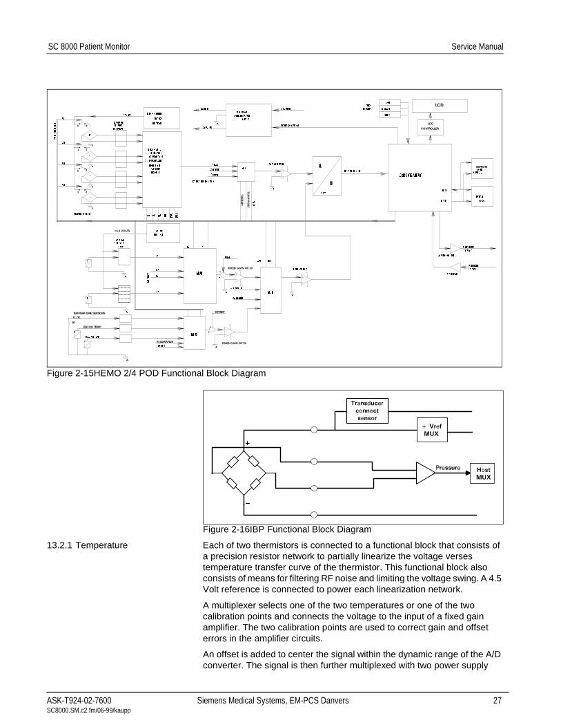
Figure 2-15HEMO 2/4 POD Functional Block Diagram
Figure 2-16IBP Functional Block Diagram
13.2.1 Temperature Each of two thermistors is connected to a functional block that consists of a precision resistor network to partially linearize the voltage verses temperature transfer curve of the thermistor. This functional block also consists of means for filtering RF noise and limiting the voltage swing. A 4.5 Volt reference is connected to power each linearization network.
A multiplexer selects one of the two temperatures or one of the two calibration points and connects the voltage to the input of a fixed gain amplifier. The two calibration points are used to correct gain and offset errors in the amplifier circuits.
An offset is added to center the signal within the dynamic range of the A/D converter. The signal is then further multiplexed with two power supply
:('*(
3527(&7(':5,7(
*5281'
%877216
386+
&2 67$57
=(52
'$7$
&/2&.
((3520
08;
),/7(5 $1'
&/$03
,1-(&7$7( 7(03
7
$
7
7
7&$7&$
2))6(7
$08;
7$7$
35(6685( 6(16256
5()(5(1&(
92/7$*(
0$1&+(67(5
'$7$ 287
&$/,%5$7,21 &2167$176
=(52/
6/
6/
6/
6/
,/
,/
,/
,/
3$
3$
9 287387
9 287387
&$3$&,725
7(&+1,48(
86,1* )/<,1*
&855(17 /,0,7('
92/7$*(
5()(5(1&(
3
3
3
3
$
$
$
$
&/$03 $1'
),/7(5,1*
1(7:25.6
',))(5(17,$/ 72
6,1*/((1'('
&219(57(5 $1'
72 08/7,3/(;(5
$
),;(' *$,1 2)
08; PP+J
PP+J
$
'
92/76
6:,7&+7,0,1*%86
%,7
6:,7&+,1* 32:(5
6833/<
$
9 ,1387
.+= 6<1& 6,*1$/
121,62/$7('
/2*,& *$7( $55$<
35(66
'$7$ $1' &21752/
0$1&+(67(5
'$7$ ,1
'$7$ 75$160,77(5
'$7$ 5(&(,9(5
9 021,725
9 021,725
$
08;
&$/32,176
7
7
7
7
/,1($5,=(
7
$
),;(' *$,1 2)
TEMPERATURE SENSORS
FIXED GAIN OF 10
AFIXED GAIN OF 20
OFFSET
+
+
A
O.7R
BLOOD TEMP
LCD
LCD
CONTROLLER
EEPROM
R/W
+4.0 VOLTS
R_EDWARDS
R?
21
21
21
21
200m
mH
GL
4PRE
SSL
ASK-T924-02-7600 Siemens Medical Systems, EM-PCS Danvers 27 SC8000.SM.c2.fm/06-99/kaupp

Service Manual SC 8000 Patient Monitor
voltage monitors and Cardiac Output. A fixed gain of two is finally applied to match the signal range to the full scale range of the A/D converter.
13.2.2 Cardiac Output Cardiac output operates in much the same way as temperature. The thermistor signals are filtered and clamped then multiplexed to the input of a fixed gain amplifier. Two calibration voltages are also multiplexed in to correct amplifier offset and gain errors.
Next, an offset is added to the signal to center it to the dynamic range of the A/D converter. The amplified signal is then multiplexed with temperature, then through a fixed gain of two and finally to the A/D converter.
13.2.3 EEPROM Storage Two EEPROM's are used for non-volatile information storage. One EEPROM is used for reading and writing data that changes during the operation of the POD, such as pressure offsets, the other stores more permanent information such as POD serial number and is therefore write protected. A state machine inside the logic gate array supports communications between the Host and the two EEPROM's. A mechanism is provided which allows service personnel to disable the write protection of the otherwise write protected EEPROM.
13.2.4 LCD and Push Buttons A total of 16 LCD characters are provided for use as pressure labels. Each pressure channel is allocated 4 LCD characters. The Logic Gate Array supports communication of controll between the Host and the LCD's.
Up to three push buttons are provided for user interface. There is one for pressure zero, one for Cardiac Output Start and one spare. The interface of the buttons to the Host is handled by the gate array.
13.2.5 Current Limiting the Voltage Reference
In the event a defective pressure sensor presents a short circuit to the excitation voltage source, the voltage source goes into current limit during the bad transducer's time slot.
14Advanced Comm Option
The SC 8000 has been designed to function in standalone mode or in an INFINITY NETWORK. It is not compatible with SIRENET.
The Comm Option PC board supplies power and communications interface for peripheral devices associated with the monitor.
14.1 Comm Option Board Hardware
The major circuits include a high speed serial link to the Patient Monitor, control and status registers to the 68302 processor, and miscellaneous functions. The serial link functions as a bus master on the local bus. The 68302 performs bus arbitration. The registers and miscellaneous functions are slave devices on the bus and completely accessible to the 68302.
((3520V 7KH&RPP2SWLRQ3&ERDUGFRQWDLQV6(5,$/((3520VZKLFKDUH
SURJUDPPHGLQWKHIDFWRU\ZLWKYDULRXVFRQILJXUDWLRQSDUDPHWHUV2QH
FRQWDLQVIDFWRU\SURJUDPPHGILHOGVHUYLFHGDWDDQGLVUHDGRQO\LQWKHILHOG
$VHFRQG((3520LVILHOGSURJUDPPDEOHDQGFRQWDLQVYDULRXV
FRQILJXUDWLRQSDUDPHWHUV
28 Siemens Medical Systems, EM-PCS, Danvers ASK-T924-02-7600SC8000.SM.c2.fm/06-99/kaupp

Chapter 3: Repair1 Introduction The following procedures are applicable to the SC 8000 Patient Monitor as
of the date of publication of this Manual. Subsequent changes may be published as a supplement and/or posted on the Siemens TD Intranet site, http://www-td.med.siemens.de/, under EM Product Information.
Before attempting to open the monitor, always do the following:
• Unplug all cables from connectors on the back and front of the monitor.
• Remove monitor cover and unplug main cable from battery.
2 Replaceable Items Refer to Figure 3-1 and Figure 3-6. The following items are available for replacement in the field. Refer to Appendix A for part numbers.
1) Front Bezel Subassembly
2) Front Bezel Language Label
3) Main Processor PCB Subassembly
4) Power Supply (OEM)
5) Optical Encoder
6) Rotary Knob
7) NBP Pump Subassembly (also see Figure 3-2 on page 34)
8) Battery
9) Speaker Subassembly (also see Figure 3-2 on page 34)
10) Connector I/O PCB (also see Figure 3-2 on page 34)
11) External Fan
12) Rear Panel w/o Adv Comm Option
13) Rear Panel w/ Adv Comm Option (See Figure 3-6 on page 40)
14) Adv Comm Option (See Figure 3-6 on page 40)
15) MIB 1&2 Option (See Figure 3-6 on page 40)
Caution
Assure that both you and the work area are properly protected against static-electricity discharge.
3
ASK-T924-02-7600 Siemens Medical Systems, EM-PCS Danvers 29 SC8000.SM.c3.fm/06-99/kaupp

Service Manual SC 8000 Patient Monitor
Figure 3-1 Basic SC 8000 Patient Monitor (shown w/o Adv. Comm. and MIB 1&2 Options - see Figure 3-6)
0 Front Bezel Subassembly
@ Channel Guide
3 Main Processor PCB Subassembly
4 Power Supply Subassembly
5 Optical Encoder Subassembly
6 Rotary Knob
7 NBP Pump Subassembly (also Figure 3-2 on page 34)
8 Battery
9 Battery Tray
Connector I/O PCB Subassembly (2 boards connected by flex cable)
Speaker Subassembly (also Figure 3-2 on page 34)
' Rear Panel (w/o installed Adv. Comm and MIB 1&2 Options)
Fan
Language Label
Top Cover
Blank Cover (if Adv. Comm and MIB 1&2 Options not installed)
a
a
a
4
56
8
10
2
131
14
7
1211
3
9
15
16
30 Siemens Medical Systems, EM-PCS, Danvers ASK-T924-02-7600SC8000.SM.c3.fm/06-99/kaupp

SC 8000 Patient Monitor Service Manual
2.1 Rotary Knob The rotary knob is press fitted onto the metal shaft of the optical encoder subassembly, and is the only component on the SC 8000 monitor that can be replaced without removing any other components of the monitor. It must be removed very carefully if it is to be reinstalled.
1) To remove the knob, grip it very firmly with vise-grips or a similar tool, and pull it straight out and off of the metal shaft. Avoid turning knob.
Note: Placing a piece of cloth around the knob should prevent scratching by the jaws of the tool, and allow the knob to be reused.
2) To install or reinstall a knob, align and firmly press knob onto shaft.
2.2 Replacing Fan Fan ( in Figure 3-1) is located behind back panel beside AC power connector, and can be replaced without removing outer case of monitor.
2.2.1 Removing Fan 1) With monitor on a clean flat surface, unplug external power cable and disconnect all signal cables from the monitor.
2) Remove and save five Phillips-head screws that secure back panel to monitor chassis.
3) Remove back panel.
Note: Required direction of fan rotation is indicated on side of fan housing.
4) Carefully unplug fan cable connector from connector on fan housing.
Caution
If the connector gets damaged, the monitor will need to be opened and the complete fan subassembly replaced.
5) Slide cable through slots in fan housing to free cable from housing.
6) Remove and save two screws that secure fan to back of chassis, and remove fan.
2.2.2 Installing Fan Reverse steps of Section 2.2.1 to install fan. Observe proper orientation of fan housing as noted in step 3.
2.3 Opening Monitor Except for Fan and Rotary Knob replacement, open monitor to access replaceable components and subassemblies. Use following procedure.
Warning
After monitor has been opened and then reassembled, always functionally verify proper operation of monitor functions as detailed in Chap. 4, before returning monitor to clinical service.
Caution
Assure that both you and the work area are properly protected against static-electricity discharge.
3
ASK-T924-02-7600 Siemens Medical Systems, EM-PCS Danvers 31 SC8000.SM.c3.fm/06-99/kaupp

Service Manual SC 8000 Patient Monitor
1) Place monitor on clean flat surface, unplug external power cable and disconnect all signal cables from monitor.
2) Remove five screws that secure Display mount to top of monitor. Set mount and screws aside for use in reassembly.
3) Remove and save five Phillips-head screws that secure back panel to monitor chassis.
Note: In SC 8000 monitors equipped with Adv Comm Option, the screw that holds the network connector bracket is a different size from the other four securing screws. Be sure to note difference when saving screws for use in reassembly.
4) Remove network connector bracket (if present) and back panel.
5) Turn monitor topside down and remove six Phillips-head screws that secure top cover to chassis along outside edges.
6) Turn monitor topside up with back of monitor facing you and slide top cover toward you to remove cover.
2.4 Battery and Tray Battery (9 in Figure 3-1 on page 30 and in Figure 3-6 on page 40) is located in tray (in Figure 3-1) behind front panel on left side above Main PCB Subassembly.
2.4.1 Removing Battery 1) Open monitor. Refer to Section 2.3.
2) Using long nose pliers or similar tool, unplug two battery connectors from main battery terminals. Note orientation of battery in tray, and routing and polarity of battery cable wires! (See illustration at left.)
3) Lift battery out of tray.
2.4.2 Removing Tray 4) If necessary to remove tray, remove and save two screws that secure tray to left side of chassis and two screws that secure tray to bulkhead.
Note: Be careful to not damage grounding strap from front panel membrane switch subassembly, secured to the bulkhead by one of the tray securing screws.
2.4.3 Installing Battery and Tray
If tray was removed, be sure to reinstall grounding strap from front panel membrane switch subassembly when reinstalling tray. Reverse steps of removal procedure to install battery and tray.
2.5 Power Supply Power supply (4 in Figure 3-1 on page 30) is located in back right-hand corner of chassis, and is secured to chassis by four screws through corners of power supply PC board into standoffs on bottom of chassis and bracket on bulkhead. Use following procedure to replace Power Supply.
2.5.1 Removing Power Supply
1) Open monitor. Refer to Section 2.3.
2) Unplug power input connector from P1 on power supply PC board.
3) Unplug Connector I/O PCB power input connector from P2 on power supply PC board.
4) Remove and save screws and nuts securing thermal sensor to power supply heat sink.
5) Remove and save Adv Comm Option Subassembly (if installed, see Section 2.13 on page 39) to access securing screw on bulkhead bracket.
6) Remove and save four screws, one in each corner of power supply PC board, securing board to standoffs on chassis.
32 Siemens Medical Systems, EM-PCS, Danvers ASK-T924-02-7600SC8000.SM.c3.fm/06-99/kaupp
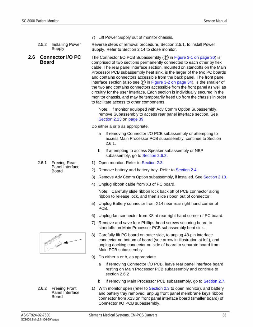
SC 8000 Patient Monitor Service Manual
7) Lift Power Supply out of monitor chassis.
2.5.2 Installing Power Supply
Reverse steps of removal procedure, Section 2.5.1, to install Power Supply. Refer to Section 2.14 to close monitor.
2.6 Connector I/O PC Board
The Connector I/O PCB Subassembly ( in Figure 3-1 on page 30) is comprised of two sections permanently connected to each other by flex cable. The rear panel interface section, mounted on standoffs on the Main Processor PCB subassembly heat sink, is the larger of the two PC boards and contains connectors accessible from the back panel. The front panel interface section (also see in Figure 3-2 on page 34), is the smaller of the two and contains connectors accessible from the front panel as well as circuitry for the user interface. Each section is individually secured in the monitor chassis, and may be temporarily freed up from the chassis in order to facilitate access to other components.
Note: If monitor equipped with Adv Comm Option Subassembly, remove Subassembly to access rear panel interface section. See Section 2.13 on page 39.
Do either a or b as appropriate.
a If removing Connector I/O PCB subassembly or attempting to access Main Processor PCB subassembly, continue to Section 2.6.1.
b If attempting to access Speaker subassembly or NBP subassembly, go to Section 2.6.2.
2.6.1 Freeing Rear Panel Interface Board
1) Open monitor. Refer to Section 2.3.
2) Remove battery and battery tray. Refer to Section 2.4.
3) Remove Adv Comm Option subassembly, if installed. See Section 2.13.
4) Unplug ribbon cable from X3 of PC board.
Note: Carefully slide ribbon lock back off of PCB connector along ribbon to release lock, and then slide ribbon out of connector.
5) Unplug Battery connector from X14 near rear right hand corner of PCB.
6) Unplug fan connector from X8 at rear right hand corner of PC board.
7) Remove and save four Phillips-head screws securing board to standoffs on Main Processor PCB subassembly heat sink.
8) Carefully lift PC board on outer side, to unplug 48-pin interface connector on bottom of board (see arrow in illustration at left), and unplug docking connector on side of board to separate board from Main PCB subassembly.
9) Do either a or b, as appropriate.
a If removing Connector I/O PCB, leave rear panel interface board resting on Main Processor PCB subassembly and continue to section 2.6.2
b If removing Main Processor PCB subassembly, go to Section 2.7.
2.6.2 Freeing Front Panel Interface Board
1) With monitor open (refer to Section 2.3 to open monitor), and battery and battery tray removed, unplug front panel membrane keys ribbon connector from X13 on front panel interface board (smaller board) of Connector I/O PCB subassembly.
ASK-T924-02-7600 Siemens Medical Systems, EM-PCS Danvers 33 SC8000.SM.c3.fm/06-99/kaupp

Service Manual SC 8000 Patient Monitor
2) Carefully remove pneumatic tubing from cuff connector on front panel.
3) Note dress of cables, and unplug following connectors from front panel interface board of Connector I/O PCB subassembly (see Figure 3-2).
• Rotary switch connector from X15
• Speaker connector from X16
• Cuff sensor connector from X10
• Pump connector from X11
• Pump valves connector from X12
4) Remove four screws securing plastic channel guide (@ in Figure 3-1 on page 30) to front of chassis.
5) Carefully pry channel guide up, and remove guide from monitor. Set guide aside for reinstallation.
Note: The guide also anchors the front panel connectors of the Main Processor PCB to the chassis.
6) Remove four Phillips-head screws that secure front panel interface board in monitor, two to chassis and two to NBP mounting bracket.
7) Slide smaller board through bulkhead to provide access to one of two screws that secure NBP mounting bracket to chassis (on some hardware revisions) or if removing Connector I/O PCB subassembly.
Note: Be observant that NBP sensor cable doesn’t snag on board.
Figure 3-2 NBP Pump Subassembly 8 and Speaker ' with front panel interface board of Connector I/O PCB Subassembly
12
11
a
A
B
8
X15 X16
X10
X11
X12
34 Siemens Medical Systems, EM-PCS, Danvers ASK-T924-02-7600SC8000.SM.c3.fm/06-99/kaupp

SC 8000 Patient Monitor Service Manual
2.6.3 Reinstalling Connector I/O PCB Subassembly
Reverse procedures of Section(s) 2.6.1 and/or 2.6.2, as applicable, to reinstall Connector I/O PCB Subassembly.
2.7 Main Processor PCB Subassembly
Main Processor PCB Subassembly (3 in Figure 3-1 on page 30) is located under larger PC board of Connector I/O PCB subassembly. It is secured in monitor by four screws into mounting posts on bottom of chassis and by channel guide on front panel. Use following procedure to replace Main Processor PCB subassembly (3 in Figure 3-1).
2.7.1 Removing Main PCB subassembly
1) If not already done, unfasten larger PC board of Connector PCB subassembly. Refer to sections 2.6 and 2.6.1.
2) Remove and save four screws securing channel guide to front panel.
3) Carefully pry channel guide up, and remove guide from monitor. Set guide aside for reinstallation.
Note: The guide also anchors front panel connectors to front panel.
4) Turn board over and rest board on right-hand side of chassis to permit access to Main PCB securing screws.
5) Remove four screws that secure Main PCB to mounting posts on bottom of chassis. Note lengths of screws so that proper screws can be reinstalled during reassembly.
6) Lift back of board sufficiently to access NBP transducer pneumatic tubing.
7) Using smooth-jaw (unserrated) needle-nose pliers or similar tool, carefully pull pneumatic tubing off of NBP transducer.
Caution
Be careful that pliers or tweezers do NOT damage the tubing.
8) Lift back of Main Processor PCB subassembly sufficiently to clear back of chassis, and remove subassembly from monitor. Take due notice of how the flex cable is dressed and routed, so that it can be reinstalled in exactly the same manner during reassembly.
Caution
Use extreme care to avoid damaging the ribbon cable or pulling the ribbon cable out of its connector on the Main Processor PCB. If either occurs, the Main Processor PCB subassembly will need to be replaced.
2.7.2 Installing Main Processor PCB Subassembly.
1) Slide pneumatic tubing from NBP pump manifold onto transducer post.
2) Angle Main Processor PCB subassembly front side down into position in chassis and seat on mounting posts. See Caution in step 8 of section 2.7.1 above.
3) Install screws removed in step 5 of section 2.7.1above.
4) Slide channel guide onto connectors on front of Main PCB, and secure to front of chassis.
ASK-T924-02-7600 Siemens Medical Systems, EM-PCS Danvers 35 SC8000.SM.c3.fm/06-99/kaupp

Service Manual SC 8000 Patient Monitor
5) Reverse procedures of Section(s) 2.6.1 and/or 2.6.2, as applicable, to reinstall Connector I/O PCB Subassembly.
2.8 Speaker Subassembly
Speaker subassembly is located under NBP pump subassembly on NBP Subassembly bracket (see ' in Figure 3-1 on page 30 and also in Figure 3-2 on page 34), and is secured to bracket by lip on bracket and two threaded studs protruding from bracket under pump subassembly. Use following procedure to replace speaker subassembly.
2.8.1 Removing Speaker
1) Remove top cover from monitor.
2) Carefully remove pneumatic tubing from cuff connector on front panel.
3) Using long-nose pliers, unplug speaker cable (A in Figure 3-2) from X16 on front panel interface board of Connector I/O PCB subassembly.
Note: Note orientation of speaker connector on X16 and cable dress.
4) Cut ty-wrap bundling speaker cable to NBP pump cables.
5) Remove four screws securing plastic channel guide to front of chassis to free connector on Front Panel Interface board.
Note: The guide also anchors the front panel connectors of the Main Processor PCB to the chassis.
6) Carefully pry channel guide up, and remove guide from monitor. Set guide aside for reinstallation.
7) Remove four Phillips-head screws that secure front panel interface PC board in monitor, two to chassis and two to NBP mounting bracket standoffs.
8) Lift inner edge of front panel interface board, and use a 5mm nut driver to remove nuts securing speaker housing to studs on NBP mounting bracket.
9) Slide speaker out from under NBP pump subassembly.
2.8.2 Installing Speaker Reverse removal procedure to install speaker subassembly. Be sure to rebundle and dress cables as noted in step 3 of Section 2.8.1.
2.9 NBP Subassembly The NBP Pump Subassembly is housed on a mounting bracket in front of the power supply. See 8 in Figure 3-1 on page 30 and in Figure 3-2 on page 34.
2.9.1 Removing NBP Subassembly
1) Open monitor, and free front panel interface board from chassis. See Section 2.6.2.
2) Cut ty-wrap loops that bundle NBP and speaker cables, and secure ferrite filters to NBP mounting bracket.
3) Remove and save two Phillips-head screws (B in Figure 3-2 on page 34) that secure NBP Pump Subassembly in mounting bracket.
4) Remove spacers between pump subassembly and mounting bracket, and pull pump subassembly away from bulkhead to free from positioning post on bulkhead.
Note: Be careful to not pull pneumatic tubing out from under Main Processor PCB Subassembly on other side of bulkhead.
5) Turn pump subassembly on right side to facilitate access, and using long-nose pliers or tweezers carefully pull NBP transducer pneumatic tubing (tubing that goes to Main Procesor PCB on other side of bulkhead) off of manifold on NBP pump.
36 Siemens Medical Systems, EM-PCS, Danvers ASK-T924-02-7600SC8000.SM.c3.fm/06-99/kaupp

SC 8000 Patient Monitor Service Manual
Caution
Be careful that the pliers or tweezers do NOT damage the tubing. Also, do NOT put any tension on the other end of the tubing, routed under Main Processor PCB Subassembly.
6) Remove NBP Pump Subassembly from bracket.
2.9.2 Installing NBP Subassembly
1) Slide NBP transducer pneumatic tubing (tubing to Main Processor PCB Subassembly on other side of bulkhead) onto manifold on pump.
Note: Be careful to not pull pneumatic tubing out from under Main Processor PCB.
2) Position spacers between pump subassembly and side of mounting bracket, and secure pump subassembly to bracket using mounting screws removed in step 3 of Section 2.9.1 above.
3) Reinstall front panel interface board. Perform steps of Section 2.6.2 in reverse.
4) Close monitor (see Section 2.14) and perform an NBP calibration check (and calibration, if required). See Chapter 4.
5) Perform an NBP characterization. Use procedure in Section 10.4 in “Chapter 4: Functional Verification and Calibration” .
Figure 3-3 Front Bezel Subassembly (incl. Membrane Keypad) 0 w/ Language Label @, Optical Encoder Subassembly 3, and R393 Access Port Cover 4
2.10 Front Bezel Subassembly
On most chassis, the Front Bezel Subassembly is secured to the chassis by five screws -- three near the top edge, accessible after the battery and tray have been removed, and two along the bottom edge, accessible from the bottom side of the monitor. See 0 in Figure 3-1 on page 30. On some chassis, the two bottom screws are installed through the front of the chassis from inside the monitor.
2.10.1 Removing Front Bezel Subassembly
1) Open monitor and remove battery and tray.
Note: If bottom securing screws for the Front Panel Subassembly are through the front of the chassis from inside the monitor, also remove Connector I/O PCB subassembly and Main Processor PCB subassembly to access the screws.
2) Unplug front panel membrane keypad ribbon connector from X13 on front panel interface PC board.
1
32
4
ASK-T924-02-7600 Siemens Medical Systems, EM-PCS Danvers 37 SC8000.SM.c3.fm/06-99/kaupp

Service Manual SC 8000 Patient Monitor
3) Carefully remove pneumatic tubing from cuff connector on front panel.
4) Unplug rotary switch connector from X15.
5) Remove four screws securing plastic channel guide to chassis front.
6) Carefully pry channel guide up, and remove guide from monitor. Set guide aside for reinstallation.
Note: The guide also anchors the front panel connectors of the Main Processor PCB to the chassis.
7) Remove five Phillips-head screws that secure Front Bezel Subassembly to chassis, and remove subassembly.
2.10.2 Installing Front Bezel Subassembly
Reverse steps of Section 2.10.1 to install Front Bezel Subassembly, and then close monitor. See Section 2.14.
Note: Install new R393 Access Port Cover if Front Bezel Slubassembly has been replaced. See 4 in Figure 3-3 on page 37.
Figure 3-4 Optical Encoder Subassembly Removal/Replacement
2.11 Replacing Optical Encoder Subassembly
1) Remove rotary knob (0 in Figure 3-4).
Note: The rotary knob is press fitted onto the metal shaft of the optical encoder subassembly. It must be removed very carefully if it is to be reinstalled. To remove knob, grip it very firmly with vise-grips or a similar tool, and pull it straight out and off of the metal shaft. Avoid turning knob. Placing a piece of cloth around knob should prevent scratching by the vise-grips, and allow knob to be reused.
2) Open monitor, and disconnect battery cable from battery terminals.
3) Unplug optical encoder ribbon cable connector (@ in Figure 3-4) from front panel interface board of Connector I/O PCB subassembly.
4) Unscrew nut 3securing optical encoder shaft in position in front bezel, and remove optical encoder subassembly 4 through back of panel. Save nut, and lock washer / positioning washer combination 5 for use in reassembly.
Reverse steps 1 through 4 to install Optical Encoder Subassembly.
1
2
3 4
5
38 Siemens Medical Systems, EM-PCS, Danvers ASK-T924-02-7600SC8000.SM.c3.fm/06-99/kaupp

SC 8000 Patient Monitor Service Manual
Figure 3-5 Removing Front Bezel Language Label
2.12 Removing/Installing Language Label
The Language Label kit ships with a set of language labels to facilitate customizing the front bezel to the language requirement of a specific customer site, if the original label becomes damaged or the bezel is replaced.
2.12.1 Removing Existing Label To remove an existing label, carefully pry up one corner of label (see arrow in Figure 3-5) and peel label off of membrane keypad towards opposite corner.
Caution
Use extreme care to not damage underlying membrane keypad when replacing Language Label. If membrane keypad is damaged the Front Bezel/Lens Subassembly must be replaced.
2.12.2 Installing Language Label 1) Peel protective covering from section of new label under function keys.
2) Position label along top of membrane keypad so that it fits squarely in label depression allowance on front bezel, and using a sweeping or rolling motion to prevent air bubbles from becoming trapped under label, press on label to secure it to membrane keypad.
3) Remove protective covering from remainder of language label, and with a similar motion affix label along right-hand side of bezel near rotary knob.
2.13 MIB 1&2 Option and Adv Comm Option Subassemblies
In the SC 8000 Patient Monitor, the MIB 1&2 Option PC board resides in the Adv Comm Option Subassembly. See in Figure 3-6 on page 40. Both MIB 1&2 Option and Adv Comm Option subassemblies must be removed to access and service Comm Connector PCB and Main PCB Subassemblies.
2.13.1 Opening Adv Comm Option Subassembly
1) Open monitor and remove battery. Refer to Sections 2.3 and 2.4.
2) Carefullly observe how tape (0 in Figure 3-7 on page 40) has been applied to outside back corner of Adv Comm Option subassembly chassis, so that the tape can be reapplied in exactly same manner. Then remove and save tape.
3) Remove and save five screws (@ in Figure 3-7) that secure Adv Comm Option subassembly cover to chassis.
4) Slide tongue of cover (3 in Figure 3-7) out from under lip at back of chassis (4 in Figure 3-7).
5) Lift cover off, and do either a or b below as appropriate.
ASK-T924-02-7600 Siemens Medical Systems, EM-PCS Danvers 39 SC8000.SM.c3.fm/06-99/kaupp

Service Manual SC 8000 Patient Monitor
Figure 3-6 Adv Comm and MIB 1&2 Options, and Rear Panel for Installed Adv Comm Option
Figure 3-7 Comm Option Subassembly Cover Removal/Installation; Location of MIB 1&2 Mounting Posts 5
11
a
16
18
15
9~
17
2
3
4
5
1
40 Siemens Medical Systems, EM-PCS, Danvers ASK-T924-02-7600SC8000.SM.c3.fm/06-99/kaupp

SC 8000 Patient Monitor Service Manual
Figure 3-8 Removing/Installing MIB 1&2 Option PC board
a) If MIB 1&2 Option installed, unplug CAN cable connector ( in Figure 3-6 on page 40) from MIB 1&2 Option PC board connector (4 in Figure 3-8). Set cover unside down beside monitor chassis and continue to step 1 of Section 2.13.2.
b) Otherwise, if MIB 1&2 Option NOT installed, unfasten loose end of CAN cable from bottom of Adv Comm Option subassembly chassis. Set cover upside down beside monitor chassis and go directly to step 1 in Section 2.13.3.
2.13.2 Removing MIB 1&2 Option
1) Remove mounting screws (3 in Figure 3-8) that secure MIB Option PCB to Adv. Comm Option chassis.
2) Unplug MIB 1&2 Option PC board (0 in Figure 3-8) from Adv. Comm Option PC board (@ in Figure 3-8), and set aside in static-protected environment if PC board is not being replaced and is to be reinstalled.
3) Reinstall screws removed in step 1 onto threaded mounting posts to safely store screws (3 in Figure 3-8) and 1/4”dia. x 3/16” (6mm dia. x 4.5mm) spacers (5 in Figure 3-7) for use in reassembly.
4) Do either a or b as appropriate.
a) If replacing only MIB 1&2 Option, go to Section 2.13.5 on page 44.
b) Otherwise, if removing Adv. Comm Option Subassembly, continue to step 1 in Section 2.13.3.
2.13.3 Removing Adv. Comm Option Subassembly
1) Note polarity of 2-wire (red/black) Adv. Comm Option power cable plugged into X17 (behind VGA connector) on rear panel interface PC board, and unplug cable.
2) Unplug network cable connector from network connector (X6) on Adv Comm Option PC board in Adv Comm Option subassembly.
Note: It may be easier to access release tab on network connector if you temporarily unplug 4-wire power cable connector from connector on rear panel interface board (X14).
3) Lift flex cable lock on each side of connector X7 (behind Recorder connector on rear panel interface board) and extract cable out of connector. (Note dress of flex cable so that cable can be reinstalled in exactly same manner during reassembly.
1
2
3 4
ASK-T924-02-7600 Siemens Medical Systems, EM-PCS Danvers 41 SC8000.SM.c3.fm/06-99/kaupp

Service Manual SC 8000 Patient Monitor
Figure 3-9 Removing/Installing Adv. Comm Option PC board
4) Remove and save four screws (0 in Figure 3-9) that secure Adv Comm Option PC board to chassis.
5) Lift side of Adv Comm Option PC board and unplug comm cable connector from COMM 1 (X4) connector on board.
6) Carefully lift Adv Comm Option PC board out of subassembly, sliding flex and power cables out of slot in side of chassis as you lift board.
Note: Be carefull to NOT remove insulating material, that adheres to slot and protects flex cable from abrasion.
7) Do either a or b as appropriate.
a) If replacing Adv Comm Option PC board, omit remaining steps in this section and go to step 5 in Section 2.13.4 on page 43.
b) Otherwise, set Adv. Comm Option PC board aside in static-protected environment and continue to step 8.
8) Reinstall screws removed in step 4, to safely store screws and 1/4”dia. x 3/16” (6mm dia. x 4.5mm) spacers (@ in Figure 3-9) on threaded mounting posts for use in reassembly.
9) Remove and save four screws (3 and 4 in Figure 3-9) that secure Adv. Comm Option subassembly chassis to threaded mounting posts on Main PC Board heat sink.
Note: Note difference between screws 3 and screw4 in Figure 3-9. Screw 4 was selected to prevent possible interference with installation of MIB 1&2 Option and must be used in mounting post indicated.
10) Lift Adv. Comm Option chassis out of SC 8000 monitor, and set aside for use in reassembly.
24
3
1
3
5
42 Siemens Medical Systems, EM-PCS, Danvers ASK-T924-02-7600SC8000.SM.c3.fm/06-99/kaupp

SC 8000 Patient Monitor Service Manual
11) Reinsert screws 3 and 4 into proper locations in threaded mounting posts on Main PCB heat sink to safely store them for use in reassembly, and then go to Section 2.6.1 on page 33 if removing Connector I/O PC board or to Section 2.5 on page 33 if removing Power Supply.
2.13.4 Installing Adv Comm Option Subassembly
1) Remove screws from threaded mounting posts on Main PCB heat sink. Note type of screw in each mounting post. See note in step 9 of Section 2.13.3 above.
2) Align holes in bottom of Adv Comm Option chassis with threaded mounting posts on Main PCB heat sink, and secure to posts using screws removed in step 1.
3) Remove four screws that secure 1/4”dia. x 3/16” (6mm dia. x 4.5mm) spacers (@ in Figure 3-9) on threaded mounting posts in bottom of Adv Comm Option chassis. Do NOT remove spacers.
4) Do either a or b as appropriate.
a) If reinstalling Adv Comm Option PC board, go to step 10.
b) If installing replacement Adv Comm Option PC board, go on to step 5.
5) Note polarity of power cable (5 in Figure 3-9) plugged into X8 on top side of previously installed Adv Comm Option PC board, and unplug cable.
6) Plug cable into replacement board connector X8 with polarity as noted in step 5 (red wire to pin 1).
7) Lift flex cable lock on each side of connector X10 on back of previously installed Adv Comm Option PC board, and extract flex cable out of connector.
Note: Note that flex cable has a front and back side. The front of the cable has identifying labeling and is against the bottom of the PC board (labeling not visible) when properly installed.
8) Slide flex cable into X10 of replacement Adv Comm Option PC board, oriented as noted in step 7, and set lock to secure flex cable in connector.
9) Plug cable connector of cable secured to comm connector on top cover of Adv Comm Option chassis into COMM 1 (X4) on Adv Comm Option PC board.
10) Carefully slide power and flex cables under insulation on slot in side of chassis as you orient Adv Comm Option PC board so that mounting holes align with four mounting posts in bottom of Adv Comm Option subassembly chassis. Refer to Figure 3-9 on page 42.
11) Secure Adv Comm Option PC board to chassis using four screws removed in step 3.
12) Plug power cable into connector X17, observing polarity noted in step 1 of Section 2.13.3 on page 41 (red wire to pin 1).
13) Seat flex cable into flex connector X7 on rear panel interface PC board and set lock to secure flex cable in connector.
14) Do either a or b as appropriate.
a) If installing MIB 1&2 Option, continue to step 1 of Section 2.13.5.
ASK-T924-02-7600 Siemens Medical Systems, EM-PCS Danvers 43 SC8000.SM.c3.fm/06-99/kaupp

Service Manual SC 8000 Patient Monitor
b) Otherwise, if NOT installing MIB 1&2 Option, go to step 1 of Section 2.13.6.
2.13.5 Installing MIB 1&2 Option
1) Remove screws reinstalled in step 3 of Section 2.13.2 on page 41.
2) Slide MIB 1&2 Option PC Board connector (0 in Figure 3-9) into connector on Comm Option PC Board (@ in Figure 3-9) and seat board in Comm Option chassis.
,QVHUWDQ\0,%([WHUQDO9HQGRU'HYLFHFDEOHLQWR0,%FRQQHFWRUWR
DVVLVWLQSURSHU0,%3&ERDUGDOLJQPHQW
,QVHUWDQGWLJKWHQPRXQWLQJVFUHZV3LQ)LJXUHWRVHFXUH0,%
2SWLRQ3&%WR&RPP2SWLRQFKDVVLV
5HPRYH0,%([WHUQDO9HQGRU'HYLFHFDEOHLQVHUWHGLQVWHS
3OXJ&$1FDEOHFRQQHFWRUIRUPHUO\WDSHGWRERWWRPRIFRPPRSWLRQ
FKDVVLVRUSOXJJHGLQWR;RQ0,%2SWLRQ3&ERDUGLQWR
FRQQHFWRURQ0,%2SWLRQ3&ERDUG4LQ)LJXUH
5HPRYHODEHOVFRYHULQJ0,%2SWLRQSRUWVRQVLGHRI6&WRS
FRYHULILQVWDOOHG
2.13.6 Closing Adv Comm Option Subassembly
1) Dress cable from Comm 1 connector on Adv Comm Option PC board so that it exits chassis via slot in side of chassis beside connector, routes along top of rear panel interface board behind Recorder connector (X5) and VGA connector (X4), and reenters Adv Comm Option chassis via slot in side of chassis near corner. Locate ferrite shield outside chassis near slot where cable reenters chassis.
2) Do either a or b, as appropriate.
a) If MIB 1&2 Option installed, dress cable from CAN connector so that ferrite filter is positioned so as to not interfere or damage any components when top cover of Adv Comm Option subassembly is secured in place.
b) If MIB 1&2 Option not installed, resecure loose end of CAN connector cable to bottom of Adv Comm Option chassis.
3) Slide top cover of Adv Comm Option subassembly onto chassis so that mounting holes in cover align with threaded holes in lip of chassis, making sure tongue on back of cover slides under lip of chassis.
,QVHUWDQGWLJKWHQILYHIODWKHDGVFUHZVUHPRYHGLQVWHSRI6HFWLRQ
RQSDJH WRVHFXUHFRYHUWRFKDVVLV
5HDSSO\SURWHFWLYHWDSHRQWREDFNFRUQHURI$GY&RPP2SWLRQ
FKDVVLVDVQRWHGLQVWHSRI6HFWLRQRQSDJH
6) Plug network cable connector into network connector on Adv Comm Option subassembly.
Note: Replug 4-wire power cable connector back into rear panel interface PC board power connector (X14), if disconnected.
&ORVH0RQLWRU5HIHUWR6HFWLRQ
2.14 Closing Monitor 1) Reinstall battery tray (if removed) and battery. See Section 2.4.3.
2) With monitor positioned topside up and back of monitor facing you, slide top cover onto monitor.
3) Turn monitor topside down, on a clean flat surface, and install six Phillips-head screws along outside edges to secure top cover to chassis.
44 Siemens Medical Systems, EM-PCS, Danvers ASK-T924-02-7600SC8000.SM.c3.fm/06-99/kaupp

SC 8000 Patient Monitor Service Manual
4) Turn monitor topside up with back of monitor facing you and set back panel into position on chassis.
5) Install five Phillips-head screws to secure back panel to chassis.
Note: If Adv Comm Option installed, be sure correct screw is used to secure network cable bracket to back panel and chassis.
6) Plug external power cable and, except for network cable, reconnect all signal cables to monitor.
7) If Connector I/O PCB subassembly or NBP Pump subassembly has been replaced, perform an NBP characterization before continuing to step 8. See Section 10.4 in “Chapter 4: Functional Verification and Calibration”. Otherwise, continue.
8) Functionally verify proper operation of monitor before returning monitor to clinical service.
Note: Be sure that reassembled monitor passes all leakage tests. Refer to procedures in Section 20 of “Chapter 4: Functional Verification and Calibration”.
ASK-T924-02-7600 Siemens Medical Systems, EM-PCS Danvers 45 SC8000.SM.c3.fm/06-99/kaupp

Service Manual SC 8000 Patient Monitor
This page intentionally blank.
46 Siemens Medical Systems, EM-PCS, Danvers ASK-T924-02-7600SC8000.SM.c3.fm/06-99/kaupp
Chapter 4: Functional Verification and Calibration1 Introduction Calibration required for proper operation of SC 8000 Patient Monitors has
been programmed into the software for the monitor. An adjustment potentiometer, however, permits calibration of the NBP transducer in the field, if required following a calibration check. Specific calibration and adjustment procedures needed in routine operations of the monitor are detailed in the User Guide for the installed software version, and are required to be performed only when directed to do so by a message in the message field on the monitor display.
If specific reading of a patient parameter is suspect, Siemens recommends functional verification for that function. Siemens recommends a full functional verification for all patient parameters, including an NBP calibration check, a pneumatic leakage check, a Temperature calibration check and a leakage current check be performed in accordance with local regulations or at least annually. In addition, re-characterization should be performed at least every two years. Refer to Section 10.4.
Note: Re-characterization and calibration checks for NBP and Temperature should be performed by only qualified personnel with the necessary equipment. Regulations in some national jurisdictions may place specific requirements on who may perform these functions
This chapter describes functional verification procedures, calibration check procedures, and NBP calibration procedures for monitors in the field. The procedures assure proper operation of the monitor, using industry-standard patient simulators and test equipment, to verify that the monitor properly processes and reports patient physiological parameter signal inputs. Record results of functional verification testing in a copy of “Appendix D: Functional Verification Checklist” on page 111.
Software and certain of the monitor’s hardware components are continually checked, first during power-up and later during on-line self-tests. All monitor functions that are tested are performing in accordance with design specifications if no error messages exhibit.
Perform all functional verification and calibration procedures with the monitor off-line. Disconnect all patient parameter signal inputs from the monitor, and plug in signal inputs from patient simulators and industry-standard test equipment only as instructed to do so. To assure that the monitor is off-line, unplug network cable from monitor.
If the monitor fails to perform as indicated for any specific function during functional verification procedures, troubleshoot the monitor using procedures in “Chapter 5: Troubleshooting” of this Manual and remedy the malfunction before attempting to complete functional verification.
2 Recommended Tools and Test Equipment
Use specified recommended tools and test equipment given in Table 4-1 below, or a known equivalent, when performing functional verification tests. Substitutions are approved only if an equivalent is listed. Use of other test equipment and/or accessories could result in inconclusive tests or damage to system components.
ASK-T924-02-7600 Siemens Medical Systems, EM-PCS Danvers 47 SC8000.SM.c4.fm/06-99/kaupp
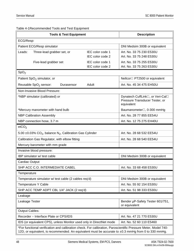
Service Manual SC 8000 Patient Monitor
Table 4-1Recommended Tools and Test Equipment
Tools & Test Equipment Description
ECG/Resp:
Patient ECG/Resp simulator DNI Medsim 300B or equivalent
Leads: Three-lead grabber set, or IEC color code 1IEC color code 2
Art. No. 33 75 230 E530UArt. No. 33 75 248 E530U
Five-lead grabber set IEC color code 1IEC color code 2
Art. No. 33 75 255 E530UArt. No. 33 75 263 E530U
SpO2
Patient SpO2 simulator, or Nellcor PT2500 or equivalent
Reusable SpO2 sensor: Durasensor Adult Art. No. 45 34 475 EH50U
Non-Invasive Blood Pressure:
*NBP simulator (calibrated) or Dynatech CuffLink, or Veri-Cal Pressure Transducer Tester, or equivalent
*Mercury manometer with hand bulb Baumanometer, 0-300 mmHg
NBP Calibration Assembly Art. No. 28 77 855 EE54U
NBP connection hose, 3.7 m Art. No. 12 75 275 EH40U
etCO2
5.00 ±0.03% CO2, balance N2, Calibration Gas Cylinder Art. No. 28 68 532 EE54U
Calibration Gas Regulator, with elbow fitting Art. No. 28 68 540 EE54U
Mercury barometer with mm grade
Invasive blood pressure:
IBP simulator w/ test cable DNI Medsim 300B or equivalent
Cardiac Output
SHP ACC C.O. INTERMEDIATE CABEL Art. No. 33 68 458 E530U
Temperature
Temperature simulator w/ test cable (2 cables req’d) DNI Medsim 300B or equivalent
Temperature Y Cable Art. No. 55 92 154 E530U
SHP ACC TEMP ADPT CBL 1/4” JACK (2 req’d) Art. No. 51 98 333 E530U
Leakage
Leakage Tester Bender µP-Safety Tester 601/751, or equivalent
Output Cables:
Recorder ÷ Interface Plate or CPS/IDS Art. No. 47 21 770 E530U
IDS (or equivalent CPS), unless Monitor used only in DirectNet mode Art. No. 52 60 110 E5460
*For functional verification and calibration check. For calibration, Paroscientific Pressure Meter, Model 740-12D, or equivalent, is recommended. An equivalent must be accurate to ±0.3 mmHg from 0 to 330 mmHg.
48 Siemens Medical Systems, EM-PCS, Danvers ASK-T924-02-7600SC8000.SM.c4.fm/06-99/kaupp

SC 8000 Patient Monitor Service Manual
3 Power Circuits and Start-up
The following procedures check the monitor’s power circuits, power-up sequence, and power off indicator. Begin this procedure with the monitor turned off and plugged into a hospital-grade power source.
3.1 Power ON/OFF 1) Press ON/OFF switch on front panel and verify that power LED in ON/OFF key turns on.
2) Press and hold ON/OFF key for approximately two seconds.
3) Verify that high pitched piezo tone sounds briefly and power LED in ON/OFF key turns off.
3.2 Power-Up Sequence Press ON/OFF key and verify following sequence of events:
• Power LED in ON/OFF key turns on.
• Display illuminates briefly, monitor beeps, high-pitched piezo tone sounds briefly, and Battery charger LED illuminates briefly.
• After a few moments, during which display is NOT illuminated, monitor sounds a chime.
• After a few more moments, New Patient prompt displays.
• Select NO, and press rotary knob in to clear prompt.
Note: With all patient inputs removed from the monitor, only “adult” and “ALL Alarms OFF” appear on MAIN screen.
• Battery charge level bar graph, date and time report in message area at bottom of display.
4 Rotary Knob The Rotary Knob in the lower right corner of the front panel controls an optical encoder for pointing to and selecting display fields and functions.
1) Press Menu key, and verify that selected menu item changes for each detent as knob is rotated one complete revolution in either direction.
2) Rotate knob until ← in upper left corner of Main Menu is selected.
3) Press knob in and verify that MAIN screen displays.
5 LCD Display The display is composed of an active-matrix LCD screen with backlight. Test the LCD display as follows:
1) With MAIN Screen displayed, verify that ≤17 Pixels are inoperative (“stuck” ON).
2) Press Menu key and select Monitor Setup → Display Options.
3) Select Brightness
4) Change setting of rotary knob and observe that brightness of display screen varies accordingly. (monitor must be on battery power)
5) Set brightness for AUTO.
6) Verify that backlite provides sufficient and uniform background illumination for LCD, while connected to external power source (CPS, IDS, PSL).
7) Verify intensity change with change in ambient light.
8) Press Main Screen key to return to MAIN screen.
6 Fixed Keys The following tests verify that membrane switches on the front panel are functioning properly, and that the signal from the key is processed by the
ASK-T924-02-7600 Siemens Medical Systems, EM-PCS Danvers 49 SC8000.SM.c4.fm/06-99/kaupp

Service Manual SC 8000 Patient Monitor
Front Panel Control PCB. Functions controlled by the fixed keys are individually verified elsewhere in this Chapter as required.
Note: Before beginning Key tests access Main menu. Select Monitor Setup → Monitor Options → Speaker Volumes, and assure that Attention Tone Volume is set to other than OFF.
6.1 ON/OFF Key The ON/OFF key initiates the power-on sequence if the monitor is powered off, and powers-off the monitor, initiating a brief power-off piezo alarm, if the monitor is powered-on.
Note: This test can be omitted if the procedure of section 3.1 has already been performed.
1) Press and momentarily hold ON/OFF key.
2) Verify that powered state of monitor changes.
3) Set monitor to powered-on state, if monitor powered off.
6.2 Main Screen Key The Main Screen key sets the display to the MAIN screen.
1) Press Menu key to display Main menu.
2) Press Main Screen key, and verify that Main menu extinguishes, and display returns to MAIN screen.
6.3 Alarm Silence Key The Alarm Silence key silences an alarm tone for one minute.
1) Assure that HR alarm is enabled, and without any input applied to MultiMed POD, plug MultiMed or MultiMed 12 cable into monitor. Monitor should Alarm.
2) Press Alarm Silence key and verify that alarm ceases.
3) Turn off HR alarm in Alarm Limits Table before proceeding. See section 6.4.
6.4 Alarm Limits Key The Alarm Limits fixed key calls up a setup table on which upper and lower alarm limits for physiologic parameters can be assigned, and alarms and alarm recordings can be enabled or disabled.
1) With MAIN screen displayed, press Alarm Limits fixed key.
2) Verify that Alarms Setup Table displays.
6.5 All Alarms Off Key The All Alarms Off key silences all alarms for a period of 2 minutes.
1) Press All Alarms Off key.
2) Verify that 2 minute countdown field appears at top center of display.
6.6 Code Key The Code key can perform any of several functions, depending on other parameter settings entered into the monitor. Refer to operating instructions in the User Guide for more detailed information. The following procedure verifies only that the monitor responds to a key press.
1) Press the key and verify that a change occurs in the display.
2) Double-click key to return display to former status.
6.7 Record Key The Record key starts and stops a recording of limited duration when the monitor is mounted on an IDS (or CPS).
1) With monitor mounted on IDS (or CPS) press Record key.
2) Verify that message “Recording Not Accepted” appears in message field at bottom right-hand side of display.
50 Siemens Medical Systems, EM-PCS, Danvers ASK-T924-02-7600SC8000.SM.c4.fm/06-99/kaupp

SC 8000 Patient Monitor Service Manual
6.8 Print Screen Key Print Screen key initiates printing a copy of the display, on network printer.
1) Press Print Screen key twice.
2) Verify that message “Printer Unavailable, Waiting” appears in message field at bottom right-hand side of display.
6.9 NBP Start/Stop Key The NBP Start/Stop key initiates or terminates the inflation cycle for the non-invasive blood pressure monitor function.
1) Press Menu key. Access Monitor Setup → Monitor Options → Speaker Volumes, and set Attention Tone Volume to 50%.
2) Press NBP Start/Stop key.
3) Verify that monitor sounds a tone. (Cuff must not be plugged into cuff connector.)
6.10 Zoom Key When a patient is being monitored, the Zoom key calls up a 1-hour trend display for a quick overview of patient status.
1) Press Zoom key, and verify that “Fast Access Menu” displays.
2) Press Main Screen key to return.
6.11 Help Key 1) Press Help key and observe that Main Help Menu appears on display.
2) Press Main Screen key to clear display.
6.12 Mark Key The Mark key inserts parameter values with time and date stamp in the tabular trends. Verify that Mark membrane switch is functional as follows:
1) Press Menu key and select Review → Trend Table.
2) Press Mark key and observe that time stamp on HR readout changes from white to green and Mark symbol appears above stamp.
7 ECG/RESP Functions
With the cable plugged into the monitor connect either a 3-lead, 5-lead, or 6-lead ECG cable from the Patient Simulator into the MultiMed POD.
7.1 ECG/RESP Test Setup 1) Select HR parameter box and press rotary knob in to bring up ECG menu.
• Set all ECG Lead settings at default values and remaining parameters as follows:
- ARR Monitoring Basic
- RESP Monitoring ON
- Pacer Detection ON
• QRS Sync MarkerON
• Pulse Tone SourceECG
• Pulse Tone Volume10%
2) Set simulator as follows:
• ECG = Normal Sinus
• HR = 80 beats per minute (bpm)
• amplitude = 1.0 mV
• RESPIRATION = Normal Rest.
• rate = 20 breaths per minute (BPM)
ASK-T924-02-7600 Siemens Medical Systems, EM-PCS Danvers 51 SC8000.SM.c4.fm/06-99/kaupp
Service Manual SC 8000 Patient Monitor
• ohms = 1.0
• LEAD SELECT = II/RA-LL
• BASELINE IMPEDANCE = 500
7.2 Waveforms/Digital Readouts/Tones
1) Verify the following:
• Waveform and HR correspond to data provided by simulator.
• Heart symbol (♥) blinks and pulse tone sounds for each QRS complex.
• White spike present at each QRS complex.
• RESP and HR digital readout correspond to settings of simulator.
2) Vary Tone Volume setting and verify that pulse tone volume changes.
3) Set Tone Volume to OFF, and verify that pulse tone stops.
7.3 Pacer Detection 1) Apply paced signal from simulator.
2) Verify that small “P” accompanies heart symbol (P♥) for every detected, paced beat, blue spike appears for each paced signal, and HR digital value agrees with pacer bpm setting.
3) Generate asystole condition in simulator, with pacer output still active.
4) Verify that ASY appears in ARR parameter box, an asystole alarm sounds, and waveform is flatline with pacer pulses.
5) Disable pacer signal, and return simulator to setup above (section 7.1).
7.4 Lead-Off Indicators 1) One at a time, disconnect each ECG lead from simulator.
2)• For LL and RA electrodes, verify “Lead-Off” and “ECG Leads Invalid” messages appear in message area, pulse tone ceases, *** replaces digital heart rate in HR field.
• For V and RL electrodes, verify “Lead-Off” message, loss of V trace.
• For LA electrode, verify “Lead-Off” message only.
3) Reconnect all leads to simulator.
7.5 Alarm Function This procedure also tests that the alarm function of the monitor, as applicable to all other patient parameters, is operational in the monitor.
1) In Alarm Limits Table, set HR alarm parameters as follows:
• Upper limit = 110 bpm
• Lower limit = 40 bpm
• Alarm = ON
2) Set emulator to HR = 120 bpm.
3) Verify that monitor responds with following Serious Alarm indications:
• HR in parameter field = 120
• HR parameter field blinks and color changes.
• Serious Alarm tone sounds.
• Message HR > 110 appears in message area at bottom of display.
4) Reset simulator to HR = 80 bpm.
52 Siemens Medical Systems, EM-PCS, Danvers ASK-T924-02-7600SC8000.SM.c4.fm/06-99/kaupp

SC 8000 Patient Monitor Service Manual
5) Verify the following:
• HR parameter field returns to normal color
• HR returns to 80
• Message area continues to report most recent alarm, HR >110.
6) Press Alarm Silence fixed key.
7) Verify that “HR > 110” ceases to be reported.
7.6 Asystole Switch power to simulator OFF. Verify that HR parameter field reports ASY, “Asystole” appears in message area at bottom of display, and monitor responds with Life-Threatening alarm.
Switch power to simulator ON.
8 SpO2 Function The SC 8000 monitors oxygen saturation (SpO2) and pulse rate using the spectrophotometric method. SpO2 software is checked on monitor power-up and also periodically while the monitor is in operation.
8.1 SpO2 Test Setup The SpO2 parameter box appears when an SpO2 input is applied to the monitor through the MultiMed POD.
1) Access SpO2 parameter box menu. Set parameters as follows:
• Pulse Tone Source - SpO2
• Pulse Tone Volume -10%
• Waveform Size - 10%
• Averaging - Normal
2) Do either of the following as appropriate:
a If using a variable SpO2 simulator, set SpO2 level to 98% and pulse rate to 70 bpm, and plug simulator into SpO2 input adapter cable to MultiMed POD.
b If using a Nellcor PT-2500 pocket tester or equivalent, plug tester into SpO2 input adapter cable to MultiMed POD.
8.2 Waveforms/Digital Readouts/Tones
1) Verify the following:
• Simulated SpO2 waveform appears, and digital SpO2 and pulse rate (PLS) values correspond to simulator settings.
• ♥ symbol blinks in SpO2 field, and pulse tone sounds synchronous
with appearance of ♥ symbol.
8.3 Pulse Tone Generator 1) Select Pulse Tone Volume in SpO2 menu.
2) Vary volume setting and verify that pulse tone volume changes.
3) Set Pulse Tone Volume to OFF, and verify that tone stops. Then reset pulse tone to ON.
4) Do either of the following as appropriate:
a If using variable simulator, change oxygen saturation value and verify that pulse tone frequency (pitch) increases as SpO2 level increases, and decreases as SpO2 level decreases.
b If using pocket tester or equivalent, replace tester with adult finger sensor and place sensor on your finger. Your SpO2 reading should
ASK-T924-02-7600 Siemens Medical Systems, EM-PCS Danvers 53 SC8000.SM.c4.fm/06-99/kaupp
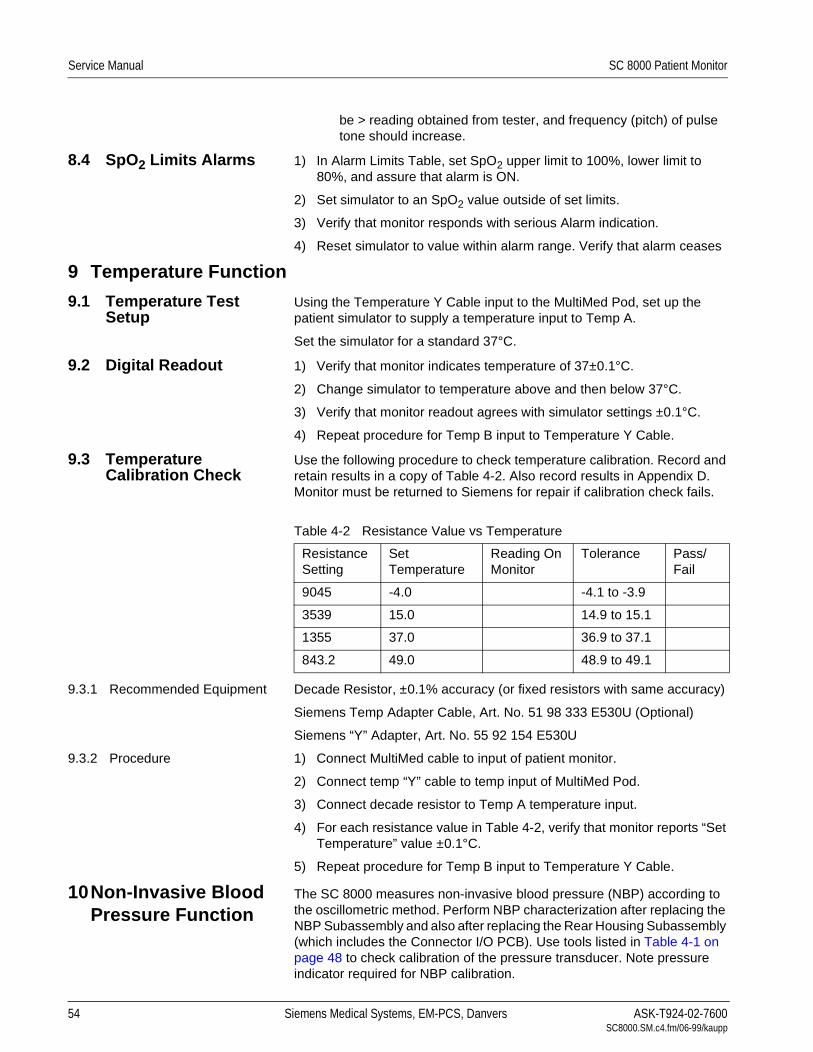
Service Manual SC 8000 Patient Monitor
be > reading obtained from tester, and frequency (pitch) of pulse tone should increase.
8.4 SpO2 Limits Alarms 1) In Alarm Limits Table, set SpO2 upper limit to 100%, lower limit to 80%, and assure that alarm is ON.
2) Set simulator to an SpO2 value outside of set limits.
3) Verify that monitor responds with serious Alarm indication.
4) Reset simulator to value within alarm range. Verify that alarm ceases
9 Temperature Function
9.1 Temperature Test Setup
Using the Temperature Y Cable input to the MultiMed Pod, set up the patient simulator to supply a temperature input to Temp A.
Set the simulator for a standard 37°C.
9.2 Digital Readout 1) Verify that monitor indicates temperature of 37±0.1°C.
2) Change simulator to temperature above and then below 37°C.
3) Verify that monitor readout agrees with simulator settings ±0.1°C.
4) Repeat procedure for Temp B input to Temperature Y Cable.
9.3 Temperature Calibration Check
Use the following procedure to check temperature calibration. Record and retain results in a copy of Table 4-2. Also record results in Appendix D. Monitor must be returned to Siemens for repair if calibration check fails.
9.3.1 Recommended Equipment Decade Resistor, ±0.1% accuracy (or fixed resistors with same accuracy)
Siemens Temp Adapter Cable, Art. No. 51 98 333 E530U (Optional)
Siemens “Y” Adapter, Art. No. 55 92 154 E530U
9.3.2 Procedure 1) Connect MultiMed cable to input of patient monitor.
2) Connect temp “Y” cable to temp input of MultiMed Pod.
3) Connect decade resistor to Temp A temperature input.
4) For each resistance value in Table 4-2, verify that monitor reports “Set Temperature” value ±0.1°C.
5) Repeat procedure for Temp B input to Temperature Y Cable.
10Non-Invasive Blood Pressure Function
The SC 8000 measures non-invasive blood pressure (NBP) according to the oscillometric method. Perform NBP characterization after replacing the NBP Subassembly and also after replacing the Rear Housing Subassembly (which includes the Connector I/O PCB). Use tools listed in Table 4-1 on page 48 to check calibration of the pressure transducer. Note pressure indicator required for NBP calibration.
Table 4-2 Resistance Value vs Temperature
Resistance Setting
Set Temperature
Reading On Monitor
Tolerance Pass/Fail
9045 -4.0 -4.1 to -3.9
3539 15.0 14.9 to 15.1
1355 37.0 36.9 to 37.1
843.2 49.0 48.9 to 49.1
54 Siemens Medical Systems, EM-PCS, Danvers ASK-T924-02-7600SC8000.SM.c4.fm/06-99/kaupp

SC 8000 Patient Monitor Service Manual
Figure 4-1 NBP Calibration Check / Calibration Test Setup
10.1 System Setup and Pneumatics Leakage Test
Set up the NBP Calibration assembly (Art. No. 28 77 855 EE54U) as illustated in Figure 4-1. Assure that pneumatic leakage is within specifications before continuing to Section 10.2, Calibration Check.
1) Assure that patient category is set to Adult.
2) Set following in NBP parameter field menu:
• Interval Time - OFF
• Continuous Mode - OFF
• Calibrate Mode - ON. (Observe “NBP Cal. = 0 mmHg” appears.)
3) Clamp pneumatic hose (with hemostat or clamp) between T-connector and monitor (0 in Figure 4-1), and using pressure bulb, increase pressure to 250 ±5 mmHg. Then clamp hose at inflation bulb (@ in Figure 4-1),and let pressure stabilize for 1 minute. Do NOT run pump.
4) Observe pressure drop for an additional 5 minutes. Drop should be <2 mmHg in 5 minutes. If not, tighten all connections and fittings and retest equipment for leakage. When leakage test OK, go on to step 5.
5) With both clamps removed, reinflate to 250±5 mmHg, if necessary, and then reclamp hose at inflation bulb.
6) Observe pressure drop for 1 minute. Drop should be <4 mmHg. If not, service monitor’s internal pneumatics system and retest system for leakage. When leakage test OK, remove clamp at inflation bulb and go on to Section 10.2.
10.2 Calibration Check Note: You may have only 2 min. to perform this test if the pump has run since the monitor was powered on, before the H/W deflation error initiates. If this happens, you will need to reset the monitor. If the pump has not run, however, there is no time limit.
1) Return to Main menu. Using hand bulb, increase pressure to 250 ±5 mmHg, if necessary, and allow it to stabilize for 1 minute.
2) Verify that pressure values displayed on monitor and pressure indicator are within ±3 mmHg of each other.
12
ASK-T924-02-7600 Siemens Medical Systems, EM-PCS Danvers 55 SC8000.SM.c4.fm/06-99/kaupp

Service Manual SC 8000 Patient Monitor
3) Slowly release pressure in 50 mmHg increments. At pressures of 200, 150, 100, and 50 mmHg, verify that pressure values on monitor and pressure indicator are within ±3 mmHg of each other at each level.
4) If NBP function fails calibration check, continue to Section 10.3. If calibration check OK, go on to Section 10.5, Hardware Overpressure.
10.3 NBP Calibration Procedure
Note: For NBP calibration, the Pressure Indicator must be accurate to ±0.3 mmHg from 0.0 mmHg to 330.0 mmHg, and must be calibrated. The calibration must be traceable to National Standards.
1) With NBP Calibrate Mode in monitor set to ON, using inflation bulb, increase pressure to 250 ±5 mmHg.
2) Clamp pneumatic hose (with hemostat or clamp) at inflation bulb.
3) Remove R393 port cover (if installed, see 9 in Figure A-1 on page 80), and adjust R393 for monitor pressure indication that matches reading on pressure indicator ±1mmHg.
Note: R393 is accessible through hole in left side of front bezel beside cable dress post. Replace covering on hole after adjustment.
4) Remove clamp and release pressure from system.
5) Perform an NBP characterization. Use procedure in Section 10.4.
10.4 NBP Characterization Note: Always perform NBP calibration check before attempting characterization. Perform NBP calibration if required.
1) Using adult hose, connect .5l pressure canister of NBP Calibration assembly directly to monitor cuff connector.
2) Press Main Menu key, and select Monitor Setup → Biomed → Service.
3) Enter service password (4712) and select Accept.
4) Select Characterization → NBP Char.
5) Verify that “NBP Characterizing” displays in message field. When message blanks, process has completed.
Note: If characterization fails, see “NBP Troubleshooting” in Chapter 5.
6) Return to Section 10.2, Calibration Check.
10.5 Hardware Overpressure
1) With monitor still in calibration mode, slowly increase pressure. while observing pressure rise on monitor’s screen.
Note: Pressure indicator accuracy of ±0.3 mmHg is not required for hardware overpressure and subsequent NBP tests.
2) Verify that pressure suddenly drops at 300 ±30 mmHg.
3) Release all remaining pressure before proceeding.
4) Set patient category to neonatal and repeat steps 1 through 3, using pressure limit of 157±8 mmHg for step 2.
10.6 Pump 1) Set Calibrate Mode in NBP parameter field menu to OFF.
2) Press NBP Start/Stop key.
3) Verify the following:
• Pressure increases and then decreases.
• Inflation and deflation pressures reported in message field.
56 Siemens Medical Systems, EM-PCS, Danvers ASK-T924-02-7600SC8000.SM.c4.fm/06-99/kaupp

SC 8000 Patient Monitor Service Manual
• Message “NBP No Pulsation” exhibits at end of deflation phase.
• All digital readouts in NBP field are ***.
10.7 Interval Mode 1) With NBP Calibrate Mode set to OFF, set Interval Time to 1 min.
2) Verify the following:
• One-minute countdown bar graph appears at bottom of NBP parameter box.
• NBP pump starts immediately when rotary switch is pressed in.
• NBP sequences through an inflation/deflation cycle and produces “NBP No Pulsation” message at bottom of display.
• NBP pump starts again when one-minute countdown bar resets to initiate another cycle.
3) Press NBP Start/Stop key to stop cycle, and reset Interval Time to OFF.
10.8 Safety Timer 1) Assure that NBP Calibrate Mode is set to OFF.
2) Press NBP Start/Stop fixed key to start pump.
3) Press same key again to stop measurement.
4) Set NBP Calibrate Mode to ON, and press MAIN SCREEN key.
5) Press CODE key to start screen stopwatch. Observe monitor screen.
6) Press CODE key again to stop watch when “NBP Cuff Deflation Error” message displays, indicating that safety timer has activated.
7) Verify that elapsed time is as follows:
• Adult 120 ±5 seconds.
• Neonatal 90 ±5 seconds
• French Homologation 60 ±5 seconds
8) Press NBP Start/Stop fixed key.
9) Verify that tone sounds and pump fails to start.
10) Power-cycle monitor to clear fault condition.
11etCO2 Function With ≥VE0 software installed in the SC 8000, the etCO2 Pod enables the SC 8000 to non-invasively monitor end-tidal CO2 (etCO2) using a technique that relies on the selective absorption properties of CO2 to specific frequencies of infrared radiation. The pod automatically compensates for variations in ambient barometric pressure if Monitor set to automatic mode. Before beginning this procedure, use a mercury column barometer or equivalent other device to determine local atmospheric pressure. Record this value.
1) Plug etCO2 Pod into Aux. connector (between Hemo Med 1 connector and NBP port) on front of Monitor .
Note: Observe that the parameter box appears on the monitor display screen, and that “etCO2 Sensor Warming Up” followed by “etCO2 Place Sensor on Zero Cell” appears in the message field.
2) While sensor is warming up, select etCO2 parameter box.
3) Assure that Atmospheric Pressure is set to “Manual”, and is set to value indicated by mercury column barometer.
ASK-T924-02-7600 Siemens Medical Systems, EM-PCS Danvers 57 SC8000.SM.c4.fm/06-99/kaupp

Service Manual SC 8000 Patient Monitor
4) Place sensor on Zero Cell.
5) Note that “etCO2 Calibrating Sensor” appears in message field, followed by “etCO2 Place Sensor on Ref Cell”.
6) Place sensor on Reference Cell.
7) Verify that”etCO2 Verifying Sensor Cal” followed by “etCO2 Sensor Cal Verified” appears in message area, and reading in etCO2 parameter box = 38 ±2mmHg.
8) Attach adult airway adapter to calibration gas cylinder. Do NOT open valve on cylinder.
Note: As CO2 is heavier than room air, set up the airway adapter such that the point where the gas exits from the adapter is higher in elevation than the point where it enters.
9) Place sensor on adult airway adapter and note reading = 0 ±1 mmHg.
10) Turn valve on the cylinder until it is fully open.
11) Wait for 30 seconds and record displayed value.
12) Close valve and remove sensor from airway.
13) Verify that measured value is in range (0.05 x local pressure) ±3, rounded to nearest integer.
14) Select etCO2 parameter box and set Atmospheric Pressure to AUTO.
15) Repeat steps 4 through 12.
16) Verify that measured value = previously measured value ±3, rounded to nearest integer.
Figure 4-2 IBP Functional Verification Test Setup for HemoMed Pod
12HemoMed Pod Refer to Figure 4-2 for test setup. Invasive blood pressure and cardiac output functions of HEMO2/4 PODs are incorporated in the HemoMed Pod. A single cable connects the Pod to the HemoMed 1input on the front of the SC 8000. Pressure labels for HemoMed Pod channels are set in the monitor.
58 Siemens Medical Systems, EM-PCS, Danvers ASK-T924-02-7600SC8000.SM.c4.fm/06-99/kaupp

SC 8000 Patient Monitor Service Manual
12.1 IBP Function12.1.1 IBP Test setup 1) With MultiMed cable and all other patient inputs unplugged from
monitor, power-cycle monitor. Select NO to clear display.
2) Plug cable from HemoMed Pod output into HemoMed 1 connector on front of Monitor. See Figure 4-2.
12.1.2 Channel A 3) With MAIN screen displayed, connect BP output from simulator to first input, channel A, on HEMO POD adapter.
4) Set IBP simulator for a static pressure = 0 mmHg.
Note: “Zero Required” message, appears on display.
Monitor Zero Function 5) Press Zero All key on HemoMed Pod.
Note: All four pressures are zeroed simultaneously in the monitor, even if only channels A and B are to be used in the HemoMed Pod.
6) Verify that a “Zero Accepted” message that changes to “Static Pressure” appear in the message field.
7) Select a pulsatile pressure on patient simulator.
8) Assure that Cal Factor and Manometer Cal are set to 100.
9) Verify that pressure reading on monitor agrees with values generated by pressure signal from simulator.
If verifying only SC 8000, omit remaining steps in this section and go to section 12.2. If also verifying HEMO POD, go on to step 10.
12.1.3 Channel B 10) Unplug BP adapter cable from channel A on HEMO POD and plug it into channel B.
11) Verify that pressure reading on monitor agrees with values generated by pressure signal from simulator.
12) Do either step a or step b as appropriate.
a If HemoMed Pod has four channels, unplug the BP adapter cable from channel B and plug it into channel C. then go on to step 13.
b If HemoMed Pod has only two channels, bypass remaining steps of this section and go to section 12.2.
12.1.4 Channel C 13) Unplug BP adapter cable from channel B on HemoMed Pod and plug it into channel C.
14) Verify that pressure reading on monitor agrees with values generated by pressure signal from simulator.
12.1.5 Channel D 15) Unplug BP adapter cable from channel C on HemoMed Pod and plug it into channel D.
16) Verify that pressure reading on monitor agrees with values generated by pressure signal from simulator.
17) Unplug simulator input adapter cable from HemoMed Pod, and go on to section 12.2.
ASK-T924-02-7600 Siemens Medical Systems, EM-PCS Danvers 59 SC8000.SM.c4.fm/06-99/kaupp

Service Manual SC 8000 Patient Monitor
Figure 4-3 IBP Functional Verification Test Setup for HEMO2/4 PODs
12.2 Cardiac Output Function
1) Plug C.O. output from simulator into C.O. test adapter cable, and plug adapter cable into C.O input on HemoMed Pod.
2) When READY appears in CO parameter field verify that blood temperature indication is 37±0.15°C.
3) Press C.O. START key on simulator, and verify an Injectate Temperature indication of 1±0.2°C.
13HEMO POD2/4 Refer to Figure 4-3 for test setup.
13.1 IBP Function IBP parameter boxes for up to two pressures for HEMO 2 POD or up to four pressures for HEMO 4 POD display automatically when IBP signal from POD is plugged into monitor, when Display Mode is set to automatic.
If verifying proper IVP functioning of only the Monitor, do sections 13.1.1 and 13.1.2, and then go on to section 13.2. If functionally verifying the HEMO POD also complete sections 13.1.3, 13.1.4, and 13.1.5.
13.1.1 IBP Test setup 1) With MultiMed cable and all other patient inputs unplugged from monitor, power-cycle monitor. Select NO to clear display.
2) Plug cable from HEMO POD IBP SC 9000 output into Aux./Hemo3 input on front of SC 8000 monitor.
13.1.2 HEMO2/4 POD Channel A 3) With MAIN screen displayed, connect BP output from simulator to first input, channel A, on HEMO POD adapter.
4) Set IBP simulator for a static pressure = 0 mmHg.
Note: “Zero Required” message, identified by same pressure label is shown in LCD window for channel A on front of HEMO POD appears on display.
0RQLWRU=HUR)XQFWLRQ 5) Press Zero All key on HEMO POD.
6) Verify that a “Zero Accepted” message that changes to “Static Pressure”, both identified by the same pressure label, appear in the message field.
7) Select a pulsatile pressure on patient simulator.
290
270
250
230
210
190
170
150
130
110
90
70
5
300
280
260
240
220
200
180
160
140
120
100
80
60
40
20
0
PressureTransducer
Tester
InflationBulb
Manometer
Stopcock(Closed)
60 Siemens Medical Systems, EM-PCS, Danvers ASK-T924-02-7600SC8000.SM.c4.fm/06-99/kaupp

SC 8000 Patient Monitor Service Manual
8) Assure that Cal Factor and Manometer Cal are set to 100.
9) Verify that pressure reading on monitor is in agreement with values generated by pressure signal from simulator.
10) Plug cable from HEMO POD IBP SC 9000 output into Aux./Hemo2 input and repeat steps 3 through 9. Otherwise, continue.
11) If functionally verifying only the SC 8000, omit the remaining steps in this section and go to section 13.2. If also functionally verifying HEMO POD, go on to step 12.
13.1.3 HEMO2/4 POD Channel B 12) Unplug BP adapter cable from channel A on HEMO POD and plug it into channel B.
13) Observe that pressure label changes to same pressure label as is shown in LCD window for channel B on front of HEMO POD.
14) Verify that pressure reading on monitor is in agreement with values generated by pressure signal from simulator.
15) Do either step a or step b as appropriate.
a If the HEMO POD has four channels, unplug the BP adapter cable from channel B and plug it into channel C. then go on to step 16.
b If the HEMO POD has only two channels, bypass remaining steps of this section and go to section 13.2.
13.1.4 HEMO4 POD Channel C 16) Unplug BP adapter cable from channel B on HEMO POD and plug it into channel C.
17) Observe that pressure label changes to same pressure label as is shown in LCD window for channel C on front of HEMO POD.
18) Verify that pressure reading on monitor is in agreement with values generated by pressure signal from simulator.
13.1.5 HEMO4 POD Channel D 19) Unplug BP adapter cable from channel C on HEMO POD and plug it into channel D.
20) Observe that pressure label changes to same pressure label as is shown in LCD window for channel D on front of HEMO POD.
21) Verify that pressure reading on monitor is in agreement with values generated by pressure signal from simulator.
22) Unplug simulator input adapter cable from HEMO POD, and go on to section 13.2.
13.2 Temperature Function To perform a temperature calibration check, refer to the procedure of Section 9.3 on page 54. Connect the decade resistor directly across the temp input to the Hemo 2/4 Pod instead of using the Y cable.
1) Plug fixed temperature (37°C) output from simulator into TEMP A connector HEMO POD.
2) Plug selectable temperature output from simulator into TEMP B connector HEMO POD, and set temperature for other than 37°C.
3) Verify the following:
• T field appears on MAIN screen
• T1a temperature = 37 ±0.1°C
• T1b temperature = simulator setting ±0.1°C.
ASK-T924-02-7600 Siemens Medical Systems, EM-PCS Danvers 61 SC8000.SM.c4.fm/06-99/kaupp

Service Manual SC 8000 Patient Monitor
4) Select Temperature field, and access TEMP1 menu.
5) Select TEMP Display and then select .
6) Verify that T1b changes to and reports temperature difference between T1a and T1b ±0.2°C.
7) Reset TEMP Display in TEMP1 menu to T1b.
8) Press Main Screen key to clear table and return to MAIN Screen.
13.3 Cardiac Output Function
1) Plug C.O. output from simulator into C.O. test adapter cable, and plug adapter cable into C.O./Temp B input on HEMO POD.
2) When READY appears in CO parameter field verify that blood temperature indication is 37±0.15°C.
3) Press C.O. START key on simulator, and verify an Injectate Temperature indication of 1±0.2°C.
14Memory Backup The monitor retains patient-related data, such as alarm limits, trends, and stored alarm recordings when it is powered off.
1) With monitor powered-up and no patient inputs applied, press Alarms Limits fixed key and change limit for any parameter.
Note: Note time on Real Time Clock.
2) Power monitor off for approximately 2 minutes, and then power it back on again.
3) After MAIN screen displays, press Alarm Limits fixed key to call up Alarm Limits Table.
4) Verify that new limit(s) you set in Step 1 have been retained, and that clock has advanced the proper amount of time.
15MIB 1&2 and CAN Options (if installed)
Omit steps 1 and 2 if MGM not used with this monitor.
1) With MAIN screen displayed on the SC 8000, connect MGM to Comm connector input on SC 8000 and to a hospital-grade power source.
2) Switch MGM power on, and verify that Agent parameter box displays on SC 8000 screen.
3) Plug MIB - External Vendor Device cable into any MIB input and into External Vendor Device port as given in Table 2 of Software Compatibility Chart, T855-xx-7600, for installed monitor software.
4) Refer to Operating Instructions for External Vendor Device to set up device as required in Table 2 of the Software Compatibility Chart.
5) Power External Vendor Device ON, and verify that vendor parameters appear on Monitor Display in accordance with MIB User Guide.
Note: If test mode not possible on External Vendor Device, only parameter and waveform templates may display on Patient Monitor. Refer to User Guide for installed softrware version for instructions on using MIB option.
16Adv Comm Option (if installed)
Functional verification of proper operation of the Adv Comm Option has been programmed into the software. To verify proper operation, connect an SDC (Surgical Display Controller) to the Adv Comm connector. The Monitor automatically performs a functional verification and reports successful completion on the Display.
∆T1
∆T1
62 Siemens Medical Systems, EM-PCS, Danvers ASK-T924-02-7600SC8000.SM.c4.fm/06-99/kaupp
SC 8000 Patient Monitor Service Manual
17Configuration This checks for proper configuration and for monitor communication via the INFINITY NETWORK.
1) Connect monitor to INFINITY NETWORK using ethernet connector on back of monitor.
2) Setup monitor for simulated patient using external patient simulator.
3) Verify that waveforms display on MVWS.
Note: If INFINITY NETWORK not equipped with MVWS, use remote view function of another monitor on network to view waveforms. Then skip step 4 and go on to Section 18.
4) Access netInfo on MVWS and verify that monitor labels are unique.
18Battery Charger Circuit
:LWKSDUWLDOO\GLVFKDUJHGEDWWHU\LQVWDOOHGLQPRQLWRUDQGPRQLWRU
XQSOXJJHGIURP$&VRXUFHEULQJXS0$,1VFUHHQ
3OXJPRQLWRULQWR$&SRZHUVRXUFHDQGDVVXUHWKDW%DWWHU\FKDUJHU
/('LVLOOXPLQDWHG
$IWHUKUXQSOXJPRQLWRUDQGYHULI\WKDWFKDUJHOHYHORQPDLQEDWWHU\
KDVLQFUHDVHG
19Recorder Function The R50 Recorder connects to the SC 8000 monitor through X13 on back of the monitor. The following procedure verifies that the monitor is communicating with the Recorder.
1) Connect known good R50 Recorder to monitor.
2) Press Menu key, and access Monitor Setup → Biomed → Service.
3) Enter Service password (4712) and select Accept.
4) Select Bedside Setup, and set Waveform Simulator to ON.
5) After monitor cycles, bring up MAIN screen.
6) Press Record fixed key.
7) Verify that recorder begins to dispense waveform printout.
8) Press Stop key on recorder to stop paper flow.
9) Press Menu key, and access Monitor Setup → Biomed → Service.
10) Enter Service password (4712) and select Accept.
11) Select Bedside Setup, and set Waveform Simulator to OFF.
20LeakageTests SC 8000 monitors are AC voltage operated devices. Leakage tests assure that under both normal and fault conditions, any leakage current does not exceed values given in Section 20.2.
20.1 Resistance Test 1) Using DMM (Fluke, model 8050A or equivalent) measure resistance between ground stud on rear panel and earth pin on the AC inlet (i.e. where the cord plugs in).
Note: Since the value of resistance is very small, you are reminded that it is necessary to account for lead resistance in the measure-ment. Prior to measuring the resistance between the ground stud on the rear panel and the earth pin on the AC inlet, connect both meter leads to the ground stud and measure the meter lead resistance. Subtract this lead resistance value from the DVM reading obtained in the ground stud / earth pin resistance measurement.
ASK-T924-02-7600 Siemens Medical Systems, EM-PCS Danvers 63 SC8000.SM.c4.fm/06-99/kaupp
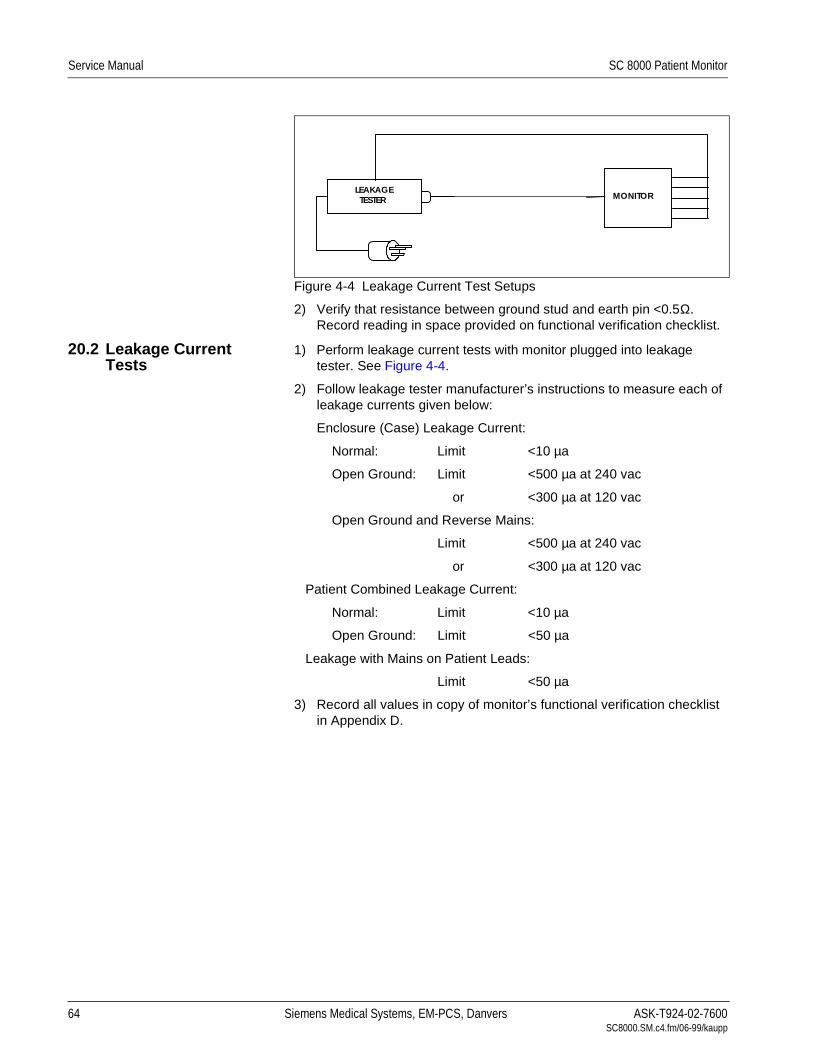
Service Manual SC 8000 Patient Monitor
.Figure 4-4 Leakage Current Test Setups
2) Verify that resistance between ground stud and earth pin <0.5Ω. Record reading in space provided on functional verification checklist.
20.2 Leakage Current Tests
1) Perform leakage current tests with monitor plugged into leakage tester. See Figure 4-4.
2) Follow leakage tester manufacturer’s instructions to measure each of leakage currents given below:
Enclosure (Case) Leakage Current:
Normal: Limit <10 µa
Open Ground: Limit <500 µa at 240 vac
or <300 µa at 120 vac
Open Ground and Reverse Mains:
Limit <500 µa at 240 vac
or <300 µa at 120 vac
Patient Combined Leakage Current:
Normal: Limit <10 µa
Open Ground: Limit <50 µa
Leakage with Mains on Patient Leads:
Limit <50 µa
3) Record all values in copy of monitor’s functional verification checklist in Appendix D.
LEAKAGETESTER
DOCKINGSTATION MONITORCPS
64 Siemens Medical Systems, EM-PCS, Danvers ASK-T924-02-7600SC8000.SM.c4.fm/06-99/kaupp

Chapter 5: Troubleshooting1 Introduction Troubleshooting SC 8000 monitors is either a two- step or three-step
process.
Step 1) Determine whether the trouble is external, such as a malfunctioning pod, connector, or cable, or internal.
Step 2) Do either a or b as appropriate.
a If external, replace malfunctioning item.
b If internal, go on to step 3.
Step 3) Usual remedial action is to replace malfunctioning component or subassembly. See “Appendix A: Replacement Parts” for complete listing of replaceable system components and subassemblies. After replacing an internal subassembly, functionally verify all monitor functions before returning monitor to clinical service.
SC 8000 monitoring system devices consist of the Base Unit, and peripheral devices including the R50 Recorder, etCO2 Pod, MultiMed or MultiMed 12 Pod, HEMO or HemoMed Pod, and VGA Display.
2 Recommended Tools and Test EquipmentUse the specified, recommended tools and test equipment, or a known equivalent, when troubleshooting SC 8000 monitors and peripheral equipment. Substitutions are approved only if an equivalent is listed. Use of other test equipment and/or accessories could result in inconclusive tests or damage to system components.
Table 5-1 Recommended Tools and Test Equipment
Tools & Test Equipment Description
Digital Multimeter (DMM), 4.5 digit Fluke, model 8050A (or equiv.)
Patient ECG/RESP, Temp, IBP simulator DNI Medsim 300B or equivalent
Leads:
Three-lead grabber set, or IEC color code 1
IEC color code 2
Art. No. 33 75 230 E530U
Art. No. 33 75 248 E530U
Five-lead grabber set IEC color code 1
IEC color code 2
Art. No. 33 75 255 E530U
Art. No. 33 75 263 E530U
Patient SpO2 simulator, or Nellcor PT2500 or equivalent
Reusable SpO2 sensor:
Durasensor, Adult Art. No. 45 34 475 EH50U
NBP simulator (calibrated) or DNI CuffLink
Mercury manometer with hand bulb, or Baumanometer, 0-300 mmHg
Electronic pressure indicator with handbulb Veri-Cal Pressure Transducer Tester, or equivalent
NBP Calibration Assembly Art. No. 28 77 855 EE54U
NBP connection hose 3.7 m Art. No. 12 75 275 EH40U
ASK-T924-02-7600 Siemens Medical Systems, EM-PCS Danvers 65 SC8000.SM.c5.fm/06-99/kaupp
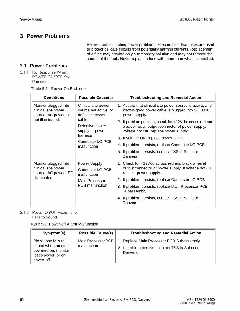
Service Manual SC 8000 Patient Monitor
3 Power ProblemsBefore troubleshooting power problems, keep in mind that fuses are used to protect delicate circuits from potentially harmful currents. Replacement of a fuse may provide only a temporary solution and may not remove the source of the fault. Never replace a fuse with other than what is specified.
3.1 Power Problems 1R5HVSRQVH:KHQ
32:(5212)).H\
3UHVVHG
3RZHU2Q2II3LH]R7RQH
)DLOVWR6RXQG
Table 5-1 Power-On Problems
Conditions Possible Cause(s) Troubleshooting and Remedial Action
Monitor plugged into clinical site power source. AC power LED not illuminated.
Clinical site power source not active, or defective power cable.
Defective power supply or power harness
Connector I/O PCB malfunction
1. Assure that clinical site power source is active, and known-good power cable is plugged into SC 8000 power supply.
2. If problem persists, check for +12Vdc across red and black wires at output connector of power supply. If voltage not OK, replace power supply.
3. If voltage OK, replace power cable.
4. If problem persists, replace Connector I/O PCB.
5. If problem persists, contact TSS in Solna or Danvers.
Monitor plugged into clinical site power source. AC power LED illuminated.
Power Supply
Connector I/O PCB malfunction
Main Processor PCB malfunction
1. Check for +12Vdc across red and black wires at output connector of power supply. If voltage not OK, replace power supply.
2. If problem persists, replace Connector I/O PCB.
3. If problem persists, replace Main Processor PCB Subassembly.
4. If problem persists, contact TSS in Solna or Danvers.
Table 5-2 Power-off Alarm Malfunction
Symptom(s) Possible Cause(s) Troubleshooting and Remedial Action
Piezo tone fails to sound when monitor powered on, monitor loses power, or on power-off.
Main Processor PCB malfunction
1. Replace Main Processor PCB Subassembly.
2. If problem persists, contact TSS in Solna or Danvers.
66 Siemens Medical Systems, EM-PCS, Danvers ASK-T924-02-7600SC8000.SM.c5.fm/09-99/kaupp
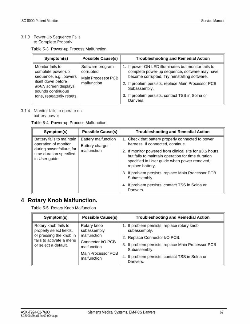
SC 8000 Patient Monitor Service Manual
3RZHU8S6HTXHQFH)DLOV
WR&RPSOHWH3URSHUO\
0RQLWRUIDLOVWRRSHUDWHRQ
EDWWHU\SRZHU
4 Rotary Knob Malfunction.
Table 5-3 Power-up Process Malfunction
Symptom(s) Possible Cause(s) Troubleshooting and Remedial Action
Monitor fails to complete power-up sequence, e.g., powers itself down before MAIN screen displays, sounds continuous tone, repeatedly resets.
Software program corrupted
Main Processor PCB malfunction
1. If power ON LED illuminates but monitor fails to complete power-up sequence, software may have become corrupted. Try reinstalling software.
2. If problem persists, replace Main Processor PCB Subassembly.
3. If problem persists, contact TSS in Solna or Danvers.
Table 5-4 Power-up Process Malfunction
Symptom(s) Possible Cause(s) Troubleshooting and Remedial Action
Battery fails to maintain operation of monitor during power failure, for time duration specified in User guide.
Battery malfunction
Battery charger malfunction
1. Check that battery properly connected to power harness. If connected, continue.
2. If monitor powered from clinical site for ≥3.5 hours but fails to maintain operation for time duration specified in User guide when power removed, replace battery.
3. If problem persists, replace Main Processor PCB Subassembly.
4. If problem persists, contact TSS in Solna or Danvers.
Table 5-5 Rotary Knob Malfunction
Symptom(s) Possible Cause(s) Troubleshooting and Remedial Action
Rotary knob fails to properly select fields, or pressing the knob in fails to activate a menu or select a default.
Rotary knob subassembly malfunction
Connector I/O PCB malfunction
Main Processor PCB malfunction
1. If problem persists, replace rotary knob subassembly.
2. Replace Connector I/O PCB.
3. If problem persists, replace Main Processor PCB Subassembly.
4. If problem persists, contact TSS in Solna or Danvers.
ASK-T924-02-7600 Siemens Medical Systems, EM-PCS Danvers 67 SC8000.SM.c5.fm/09-99/kaupp

Service Manual SC 8000 Patient Monitor
5 Fan Malfunction.
6 VGA Display Malfunction .
7 Fixed Key Fails to Function.
8 Isolating Cable MalfunctionsIn general, the troubleshooting and repair approach for cable malfunctions is to use a known input signal for any given parameter, and then replace a cable or sensor found to be malfunctioning. Cable malfunctions, including those associated with connectors on the cables, generally fall into one of three cagegories -- Open circuits, Short circuits, and Intermittent conditions
Table 5-6 Fan Malfunction
Symptom(s) Possible Cause(s) Troubleshooting and Remedial Action
Monitor completes normal power-up sequence but fan fails to start.
Fan or temp sensor malfunction
Connector I/O PCB malfunction
1. Replace Fan subassembly.
2. If problem persists, replace Connector I/O PCB.
3. If problem persists, contact TSS in Solna or Danvers.
Table 5-7 VGA Display Malfunction
Symptom(s) Possible Cause(s) Troubleshooting and Remedial Action
Display powers on, but waveforms fail to appear on screen
VGA cable malfunction
Display malfunction
Connector I/O PCB malfunction
Main Processor PCB malfunction
1. Replace VGA cable with known-good cable.
2. If problem persists, replace VGA Display with known-good Display.
3. If problem persists, replace Connector I/O PCB.
4. If problem persists, replace Main Processor PCB Subassembly.
5. If problem persists, contact TSS in Solna or Danvers.
Areas of display missing or color contaminated
Connector I/O PCB malfunction
Graphics Processor on Main Processor PCB malfunction
1. Replace Connector I/O PCB.
2. If problem persists, replace Main Processor PCB Subassembly.
3. If problem persists, contact TSS in Solna or Danvers.
Table 5-8 Fixed Key Malfunction
Symptom(s) Possible Cause(s) Troubleshooting and Remedial Action
A Fixed Key fails to initiate change
Front Bezel malfunction
Connector I/O PCB malfunction
Main Processor PCB malfunction
1. Replace Front Bezel Subassembly.
2. Replace Connector I/O PCB.
3. If problem persists, replace Main Processor PCB Subassembly.
4. If problem persists, contact TSS in Solna or Danvers.
68 Siemens Medical Systems, EM-PCS, Danvers ASK-T924-02-7600SC8000.SM.c5.fm/09-99/kaupp

SC 8000 Patient Monitor Service Manual
Open circuits and short circuits manifest themselves as a loss of signal. Software in the Monitor senses the loss, and generates an error message such as “ECG Leads Off” and “SpO2 Transparent.” Typically, short circuits result in software resets.
An intermittent condition manifests itself as noise on the signal. The source of the noise can often be isolated by removing the signal and shorting the input(s) to the cable. Then flex along the cable, particularly at connectors, while watching for noise indications on the monitor display.
9 Visible or Audible Alarm Reporting Failure.Table 5-9 Alarm Malfunctions
Symptom(s) Possible Cause(s) Troubleshooting and Remedial Action
Audible Alarm O.K., but Visible Alarm Fails.
Software problem 1. Try reinstalling software.
2. If problem persists, contact TSS in Solna or Danvers.
Visible Alarm O.K., but Audible Alarm Fails.
Speaker malfunction
Connector I/O PCB malfunction
Main Processor PCB malfunction
1. Power-cycle monitor and listen for tone after icon appears on power-up screen (not the piezo, which sounds before the icon appears).
2. If tone fails to sound, replace Speaker Subassembly.
3. If problem persists, replace Connector I/O PCB.
4. If problem persists, replace Main Processor PCB Subassembly.
5. If problem persists, contact TSS in Solna or Danvers.
ASK-T924-02-7600 Siemens Medical Systems, EM-PCS Danvers 69 SC8000.SM.c5.fm/09-99/kaupp

Service Manual SC 8000 Patient Monitor
10MultiMed POD - Parameter Signal ProblemsTable 5-10Parameter Signal Problems
Symptom(s) Possible Cause(s) Troubleshooting and Remedial Action
Failure to report lead-off condition
MultiMed POD malfunction
Main Processor PCB malfunction
1. Check MultiMed Pod contadct for possible contamina-tion. Clean if required. If problem persists, replace Pod.
2. If problem persists, replace Main Processor PCB Subassembly.
3. If problem persists, contact TSS in Solna or Danvers.
ECG/Resp waveform noise
Incorrect setting of line frequency for customer site
Poor connection or intermittent break
MultiMed POD malfunction
Main Processor PCB malfunction
1. Access the Service Menu under Monitor Setup → Biomed → Service in the Main menu.
2. Assure that the setting is proper for the frequency of the power source at the customer site.
3. If problem persists, check cables, connections, and MultiMed POD for intermittent breaks.
4. Connect grabber connectors of an ECG lead set to a common conductor, such as the shank of a screwdriver blade, to produce a flatline ECG waveform.
5. Watch for a distinct change in noise level, indicating the source of the problem, as you flex each lead and cable (particularly at connectors).
6. Replace a defective ECG lead, cable, or MultiMed POD
7. If no cable, connector, or POD problem, replace Main Processor PCB Subassembly.
8. If problem persists, contact TSS in Solna or Danvers.
SpO2 parameter box fails to appear when sensor plugged into MultiMed POD, or SpO2 readings missing
Sensor malfunction
Open cable or connector
MultiMed POD malfunction
Main Processor PCB malfunction
1. Check illumination of red LED in the sensor.
2. • If LED not illuminated, replace sensor and continue to step 3.
• If LED illuminated, place sensor on your finger and go on to step 3.
3. If problem persists, replace intermediate cable between sensor and MultiMed POD.
4. If problem persists, replace MultiMed POD.
5. If problem persists, replace Main Processor PCB Subassembly.
6. If problem persists, contact TSS in Solna or Danvers.
70 Siemens Medical Systems, EM-PCS, Danvers ASK-T924-02-7600SC8000.SM.c5.fm/09-99/kaupp

SC 8000 Patient Monitor Service Manual
11NBP
11.1 NBP Error Messages NBP Open Line Results if the NBP measurement circuit does not sense pressure changes
after initiating inflation. Possible causes include an open line out to the patient, an open or occluded line on the pressure measurement line running between the NBP assembly and the pressure transducer on the main processor board, a leaky cuff or cuff connector, or a defective valve on the NBP pump assembly.
NBP Blocked Line Result of the NBP measurement circuit detecting an occlusion on the line to the patient, or a neonatal cuff with monitor in adult mode.
NBP Overpressure Result attributable to hardware or software detecting overpressure.
NBP Cuff Deflation Error Result of the two minute NBP measurement timer expiring. It is typically triggered when an NBP measurement had been taken prior to placing the unit in calibration mode. (When calibrating, power-cycle monitor and then don’t run pump until after calibration.)
NBP Artifact Result of erratic pressure values being sensed and could be related to an application problem or could caused by an intermittent connection to the sense line.
11.2 NBP Troubleshooting Before attempting to troubleshoot NBP malfunctions, do the following:
1) Set up NBP Calibration assembly.
2) Perform leakage test on fixed volume and hose, and on system. Refer to Section 10.1 in Chapter 4.
3) Check calibration. Refer to Section 10.2 in Chapter 4.
4) If problem persists, continue with troubleshooting procedures.
SpO2 waveform noise Poor connection or intermittent break in cable
MultiMed POD malfunction
Main Processor PCB malfunction
1. With the SpO2 sensor on your finger, observe the waveform while you flex the lead and cable, particularly at the sensor, at connectors, and at the MultiMed POD.
2. Watch for a distinct change in the waveform (distinctly different from artifact) as you flex along the length of the cables as well as at the sensor and connectors.
3. Replace a defective sensor, cable or MultiMed POD.
4. If no cable, connector, or POD problem, replace Main Processor PCB Subassembly.
5. If problem persists, contact TSS in Solna or Danvers.
Temp parameter box fails to appear when sensor plugged into MultiMed POD, Temp readings missing or inaccurate
Sensor malfunction
Open cable or connector
POD malfunction
Main Processor Board malfunction
1. Replace sensor
2. If problem persists, replace MultiMed POD.
3. If problem persists, replace Main Processor PCB Subassembly.
4. If problem persists, contact TSS in Solna or Danvers.
Table 5-10Parameter Signal Problems (Continued)
Symptom(s) Possible Cause(s) Troubleshooting and Remedial Action
ASK-T924-02-7600 Siemens Medical Systems, EM-PCS Danvers 71 SC8000.SM.c5.fm/09-99/kaupp

Service Manual SC 8000 Patient Monitor
Table 5-11NBP Malfunctions
Symptom(s) Possible Cause(s) Troubleshooting and Remedial Action
NBP fails to zero properly, fails characterization, or fails calibration check
NBP pneumatic system malfunction
Main Processor PCB malfunction
1. If monitor fails calibration, perform characterization procedure. Refer to Section 10.4 in Chapter 4.
2. If monitor fails characterization or problem persists, open monitor and assure NBP transducer tubing properly routed and unobstructed.
3. If problem persists, replace NBP Subassembly.
4. If problem persists, replace Main Processor PCB Subassembly.
5. If problem persists, contact TSS in Solna or Danvers.
NBP pump fails to start/stop when NBP key on front panel is pressed
Front Bezel malfunction
Connector I/O PCB malfunction
NBP pump subassembly malfunction
Main Processor PCB malfunction
1. If pump fails to start and no error message displays, replace Front Bezel Subassembly.
2. If monitor reporting NBP in fault mode, or error message displays, power-cycle monitor.
3. If problem persists, replace Connector I/O PCB.
4. If problem persists, replace Main Processor PCB Subassembly.
5. If problem persists, contact TSS in Solna or Danvers.
NBP pump starts, but cuff fails to inflate/deflate properly
Cuff assembly malfunction
NBP pneumatic system malfunction
1. Recheck cuff assembly and installation, and replace cuff assembly if defective.
2. If problem persists, open monitor and check that pneumatic tubing to NBP transducer properly routed and not obstructed.
3. If problem persists, replace NBP Subassembly.
4. If problem persists, contact TSS in Solna or Danvers.
NBP parameter box fails to appear when cuff hose plugged into NBP module
MAIN screen display mode set for Manual
Cuff sensor defective or not plugged into Connector I/O PC Board.
Main Processor PCB malfunction
1. Assure MAIN screen display mode set to automatic.
2. If parameter box fails to appear, remove monitor cover and check that cuff sensor cable is plugged into X8 on Connector I/O PC Board.
3. • If sensor unplugged, plug sensor into X8 on Connector I/O PC Board, and reinstall monitor cover.
• If sensor plugged in, unplug sensor and check for continuity across pins of sensor cable connector. If continuity O.K. (≈ 1.5 Ω), replace Connector I/O PC Board.
4. If problem persists, replace Main Processor PCB Subassembly.
5. If problem persists, contact TSS in Solna or Danvers.
72 Siemens Medical Systems, EM-PCS, Danvers ASK-T924-02-7600SC8000.SM.c5.fm/09-99/kaupp

SC 8000 Patient Monitor Service Manual
12etCO2 Malfunction.
13HEMO2/4 Pod / HemoMed Pod
13.1 Readings Missing or Inaccurate
Disruption in communications to an external pod is caused by the pod itself, by a cable problem, or by a communication problem on the main processor board. Power for an external pod is supplied from the main processor board when the board senses that a load is present . If the monitor is not reporting connection of a Hemo2/4 pod, 12-lead pod or tcpO2/CO2 pod, use the following test to determine first whether or not the pod is being detected.
Note: Only the Hemo2/4 pod “communicates” with the monitor. The Hemo2/4 Pod is a digital device; the HemoMed Pod is analog.
Connect a 150Ω ¼W resistor between pins 1 and 3 on the suspect port (see illustration at left), and check monitor display for a pod connection error “DEVICE FAILURE ON HEMO CONNECTOR x.”
• If no error message displays, the problem is on the main processor board. Replace the Main Processor PCB Subassembly.
• If error message displays, problem may be in cable, pod, or main processor board. Replace defective component as required.
If only one input or output on a HEMO2/4 or HemoMed Pod fails to function, try replacing the sensor or cable. If problem persists, replace the Pod.
Table 5-12etCO2 Malfunctions
Symptom(s) Possible Cause(s) Troubleshooting and Remedial Action
Parameter box fails to appear when sensor plugged into pod
Sensor or cable malfunction
etCO2 pod malfunction
Main Processor PCB malfunction
1. Be sure etCO2 cable plugged into AUX connector on front of SC 8000. If problem persists, continue.
2. Clean calibration windows.
3. Replace etCO2 Sensor.
4. If problem persists, replace etCO2 pod.
5. If problem persists, replace Main Processor PCB Subassembly.
6. If problem persists, contact TSS in Solna or Danvers.
Sensor fails calibration
Sensor or cable malfunction
etCO2 pod malfunction
Main Processor PCB malfunction
1. Replace etCO2 Sensor.
2. If problem persists, replace etCO2 pod.
3. If problem persists, replace Main Processor PCB Subassembly.
4. If problem persists, contact TSS in Solna or Danvers.
Persistent Adapter Failure message
Airway adapter or sensor window occluded
Airway adapter malfunction
Sensor malfunction
1. If adapter or sensor window occluded, clean window.
2. If problem persists, replace airway adapter.
3. If problem persists, replace sensor.
4. If problem persists, replace etCO2 pod.
150Ω$X[+HPR
RU
$X[+HPR
ASK-T924-02-7600 Siemens Medical Systems, EM-PCS Danvers 73 SC8000.SM.c5.fm/09-99/kaupp

Service Manual SC 8000 Patient Monitor
13.2 IBP Malfunctions.Table 5-13IBP Malfunctions
Conditions Possible Cause(s) Troubleshooting and Remedial Action
Zero All key, C.O.Start key or Wedge key on Pod fails to initiate function
Pod malfunction
Cable malfunction
Main Processor PCB malfunction
1. Try replacing Pod / monitor cable.
2. If problem persists, replace Pod.
3. If problem persists, replace Main Processor PCB Subassembly.
4. If problem persists, contact TSS in Solna or Danvers.
IBP fails to zero properly or fails calibration check
Cable malfunction
Pod malfunction
Main Processor PCB malfunction
1. Unplug all patient parameter inputs to the monitor.
2. Set Patient simulator for an IBP static pressure = 0 mmHg, and plug simulator into Pod.
3. Plug Pod output cable into monitor.
4. Check that “Zero Required” appears in message field and that IBP parameter box appears on display.
5. If either message or parameter box fails to appear, replace Pod and cable with known-good Pod and cable.
6. If problem persists, replace Main Processor PCB Subassembly. Otherwise, continue.
7. Select IBP parameter field on MAIN screen, and assure that Cal Factor is set to 100.
8. Select Zero in menu, and press in on rotary knob.
9. • If “Zero Accepted” appears in message field, continue.
• If “--- Did Not Zero” appears in message field, replace Main Processor PCB Subassembly, if not already replaced in step 6. If Main Processor PCB Subassembly already replaced, return monitor to Siemens for repair or exchange.
10.Increase simulator pressure to 100 mmHg.
11. • If monitor reading = 100 ±1 mmHg, return monitor to clinical service.
• If monitor reading ≠ 100 ±1 mmHg, replace Main Processor PCB Subassembly, if not already replaced in step 6 or step 9. If Main Processor PCB Subassembly already replaced, contact TSS in Solna or Danvers.
74 Siemens Medical Systems, EM-PCS, Danvers ASK-T924-02-7600SC8000.SM.c5.fm/09-99/kaupp

SC 8000 Patient Monitor Service Manual
13.3 No Printout from Recorder.
IBP or Temp (HEMO2/4 Pod only) parameter box fails to appear when sensor plugged into Pod
Defective sensor or cable
Pod malfunction
Pod / Monitor cable malfunction
Main Processor PCB malfunction
1. Replace sensor and cable with known-good sensor and cable. If problem persists, continue.
2. • With HEMO2/4 connected to the monitor, assure that parameter labels are visible in LED windows on HEMO Pod.
• If HemoMed Pod, go on to step 4.
3. • If labels are visible, replace sensor. If problem persists, go on to step 4.
• If labels NOT visible, try replacing HEMO POD / Monitor interconnecting cable. If problem persists, continue.
4. Replace Pod.
5. If problem persists, replace Main Processor PCB Subassembly.
6. If problem persists, contact TSS in Solna or Danvers.
Table 5-13IBP Malfunctions (Continued)
Conditions Possible Cause(s) Troubleshooting and Remedial Action
Table 5-14Recorder Problems
Conditions Possible Cause(s) Troubleshooting and Remedial Action
Recorder connected directly to Monitor
Power LED on Recorder NOT illuminated
Recorder malfunction
Cabling malfunction
Interface Plate (if installed) malfunction
Connector I/O PCB malfunction
Main Processor PCB malfunction
1. Detach Interface Plate from Recorder and check voltage between pins 1 and 2 on Interface Plate docking connector. See illustration below.
2. If voltage OK, replace Recorder.
3. If voltage OK, check for +12VDC between pins 2 and 15 of X13 on monitor.
• If voltage OK replace cable.
• If voltage not OK replace Connector I/O PCB.
4. If problem persists, replace Main Processor PCB Subassembly.
5. If problem persists, contact TSS in Solna or Danvers.
,QWHUIDFH3ODWH'RFNLQJ&RQQHFWRU
ASK-T924-02-7600 Siemens Medical Systems, EM-PCS Danvers 75 SC8000.SM.c5.fm/09-99/kaupp

Service Manual SC 8000 Patient Monitor
14Patient-Related Data Not Retained, or Monitor Fails to Compute Trends 5HSODFH0DLQ3URFHVVRU3&%6XEDVVHPEO\
,ISUREOHPSHUVLVWVFRQWDFW766LQ6ROQDRULQ'DQYHUV
15Software Loading ProblemsFor problems concerning software downloads, refer to software installation instructions for version of software you are attempting to install.
16Difficulty acquiring export protocol dataThis problem is usually caused by an incorrect connection or communications protocol. Refer to INFINITY RS-232 Export Protocol Reference Booklet, Art. No. 64 93 212 E315U.
17Total or partial loss of network communicationsTemporary network communication losses are caused by either an inter-ruption with the Ethernet port on the main processor or in the network line.
1) Verify that network configuration data in monitor are correct. See Section 3 “Configuration Parameters” and Section 4 “Configuring Monitor” in “Appendix E: Service Setup Instructions”.
2) Replace Main Processor PCB Subassembly if problem isolated to monitor.
Recorder connected directly to Monitor
Recorder power LED illuminated
Recorder malfunction
Interconnecting cable or connection malfunction
Connector I/O PCB malfunction
Main Processor PCB malfunction
1. With an ECG waveform on Monitor display, provided by patient simulator, press Record key.
2. • If “Recorder Not Connected” message appears in the message field, go to step 3.
• Press Zoom key and select Event Recall. After ≈20 sec, BED TIMED strip should appear on display. If BED TIMED strip fails to appear, replace Connector I/O PCB and go to step 7. Otherwise, continue.
3. If problem persists, and Recorder Cable Art. No. 4318130E530U is installed, replace Recorder cable and go to step 5.
4. If problem persists, replace Recorder Interface Plate.
5. If problem persists, replace Recorder.
6. If problem persists, replace Connector I/O PCB.
7. If problem persists, replace Main Processor PCB Subassembly.
8. If problem persists, contact TSS in Solna or Danvers.
Table 5-14Recorder Problems (Continued)
Conditions Possible Cause(s) Troubleshooting and Remedial Action
76 Siemens Medical Systems, EM-PCS, Danvers ASK-T924-02-7600SC8000.SM.c5.fm/09-99/kaupp

SC 8000 Patient Monitor Service Manual
Problem ReportSC Series Patient Monitoring
Enter all applicable data in the spaces provided, and include a copy of this form when faxing a request for technical
assistance.
Name of contact
Telephone
Fax
Email Address (If available)
Monitoring Site: Country:
Region / State / Province:
Hospital or Clinical Site:
Device Type:
Device Serial Number:
Device Operating Software:
Care Unit Type:
Parameters being monitored at time of fault:
Network / Stand-alone Use
Brief Description of Fault:
_________________________________________________________________________________________
_________________________________________________________________________________________
_________________________________________________________________________________________
_________________________________________________________________________________________
Can the problem be reproduced or is the problem intermittent?
Has TSS been previously contacted concerning this problem?
Has a customer complaint on this product been filed?
Complaint Reference Number (If applicable)
Fax inquiry to:
TSS SOLNA 46-8-98-66-62
TSS DANVERS 978-907-7546
ASK-T924-02-7600 Siemens Medical Systems, EM-PCS Danvers 77 SC8000.SM.c5.fm/09-99/kaupp

Service Manual SC 8000 Patient Monitor
This page intentionally blank.
78 Siemens Medical Systems, EM-PCS, Danvers ASK-T924-02-7600SC8000.SM.c5.fm/09-99/kaupp

Appendix A: Replacement PartsRefer to the Figures and corresponding Tables in this appendix for a listing of replacement subassemblies and components. The lists contain all information available as of the publication date of this Manual. Field experience and technological development, however, may require future modifications. Subsequent changes may be published as a supplement, as well as posted on the Siemens Intranet Med UPTIME Services Online Service Support, http://www-td.med.siemens.de/, under Product Information, EM Systems, PCS.
ASK-T898-02-7600 Siemens Medical Systems, EM-PCS Danvers 79 apoloapa.sm/07-98/kaupp

Service Manual SC 8000 Patient Monitor
Figure A-1 Basic SC 8000 Monitor (Top Cover Removed)
1
~
~
11
3
5
6
~
2
8
7
10
4
12
9
Table A-1 Basic SC 8000 Monitor - Replaceable Parts/Subassemblies
Item No. Description Siemens Article
Number
1 Battery 59 43 563 E549U2 Connector I/O PCB 57 37 577 E549U3 NBP Pump Subassembly 59 43 571 E549U4 NBP Air Intake Filter 28 66 726 E516U5 Speaker Subassembly 51 94 365 E522U6 Power Supply 57 38 450 B33057 Power Supply Harness 57 38 013 E549U8 Power Supply Entry Module / Harness 57 38 468 E549U9 R393 Access Port Cover 59 56 979 E549U10 Fan 57 40 936 E549U11 Main Processor PCB Subassembly 57 40 050 E549U12 Rear Bezel w/o installed Adv. Comm Option 57 36 470 E549U13 Top Cover 57 36 397 E549U
80 Siemens Medical Systems, EM-PCS, Danvers ASK-T924-02-7600SC8000.SM.apa.fm/06-99/kaupp

SC 8000 Patient Monitor Service Manual
Figure A-2 Front Bezel Subassembly and Top Cover
1
342 6
5
Table A-2 Front Bezel Subassembly and Top Cover 5HSODFHDEOH3DUWV6XEDVVHPEOLHV
Item No. Description Siemens Article
Number
1 Front Bezel Subassembly 59 43 597 E549U2 Label Kit for Front Panel 59 43 589 E549U3 Optical Encoder Subassembly 43 11 622 E533U4 Rotary Knob 43 16 662 E533U5 R393 Access Port Cover 59 56 979 E549U6 Top Cover 57 36 397 E549U
ASK-T924-02-7600 Siemens Medical Systems, EM-PCS Danvers 81 SC8000.SM.apa.fm/06-99/kaupp

Service Manual SC 8000 Patient Monitor
Figure A-3 Adv Comm and MIB 1&2 Options
Table A-3 Adv Comm and MIB 1&2 Options5HSODFHDEOH3DUWV6XEDVVHPEOLHV
Item No. Description Siemens Article
Number
1 MIB 1&2 PCB 50 90 794 E530U2 IDS Adv Comm PCB 59 48 356 E549U3 14-P USD Adv Comm Cable Asy 59 49 693 E549U4 CAN Adv Com Cable Asy 59 49 685 E549U5 Rear Bezel w/ Adv Comm Option 59 47 630 E549U6 Ethernet Interconnect Cable 57 40 985 E549U
1
2
3
45
6
82 Siemens Medical Systems, EM-PCS, Danvers ASK-T924-02-7600SC8000.SM.apa.fm/06-99/kaupp

SC 8000 Patient Monitor Service Manual
$SSHQGL[%&RQQHFWRU&DEOH3LQRXWV
Figure B-1 Front Panel Connectors (shown for Monitor w/ ≥VE0 software installed)
Figure B-2 Rear Panel Connectors (shown for Monitor without Adv. Comm. Option installed)
Figure B-3 Rear Panel Connectors (shown for Monitor with Adv. Comm. Option Installed)
0XOWL0HG $X[+HPR $X[+HPR +HPR0HG 1%3 $QDORJ6\QF
ASK-T924-02-7600 Siemens Medical Systems, EM-PCS Danvers 83 SC8000.SM.apb.fm/06-99/kaupp
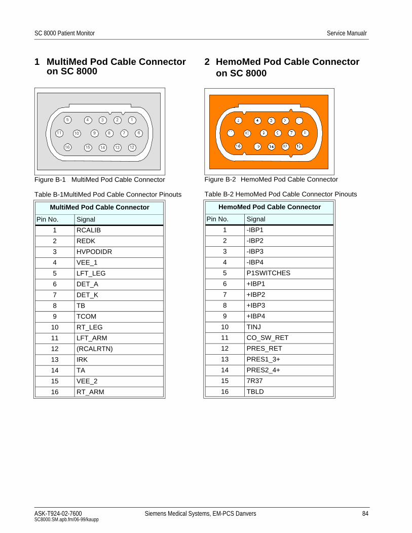
SC 8000 Patient Monitor Service Manualr
1 MultiMed Pod Cable Connector on SC 8000
Figure B-1 MultiMed Pod Cable Connector
Table B-1MultiMed Pod Cable Connector Pinouts
MultiMed Pod Cable Connector
Pin No. Signal
1 RCALIB
2 REDK
3 HVPODIDR
4 VEE_1
5 LFT_LEG
6 DET_A
7 DET_K
8 TB
9 TCOM
10 RT_LEG
11 LFT_ARM
12 (RCALRTN)
13 IRK
14 TA
15 VEE_2
16 RT_ARM
2 HemoMed Pod Cable Connector on SC 8000
Figure B-2 HemoMed Pod Cable Connector
Table B-2 HemoMed Pod Cable Connector Pinouts
HemoMed Pod Cable Connector
Pin No. Signal
1 -IBP1
2 -IBP2
3 -IBP3
4 -IBP4
5 P1SWITCHES
6 +IBP1
7 +IBP2
8 +IBP3
9 +IBP4
10 TINJ
11 CO_SW_RET
12 PRES_RET
13 PRES1_3+
14 PRES2_4+
15 7R37
16 TBLD
ASK-T924-02-7600 Siemens Medical SystSC8000.SM.apb.fm/06-99/kaupp
ems, EM-PCS Danvers 84
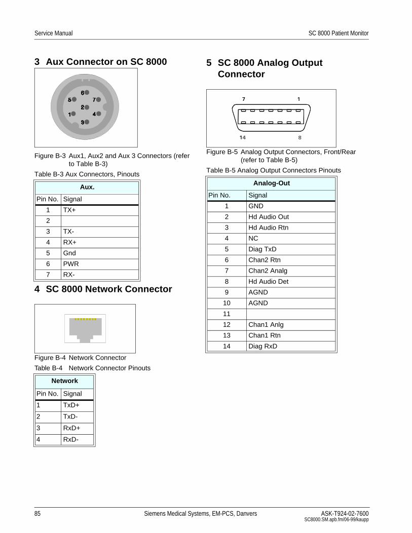
Service Manual SC 8000 Patient Monitor
3 Aux Connector on SC 8000
Figure B-3 Aux1, Aux2 and Aux 3 Connectors (refer to Table B-3)
4 SC 8000 Network Connector
Figure B-4 Network Connector
Table B-3 Aux Connectors, Pinouts
Aux.
Pin No. Signal
1 TX+
2
3 TX-
4 RX+
5 Gnd
6 PWR
7 RX-
Table B-4 Network Connector Pinouts
Network
Pin No. Signal
1 TxD+
2 TxD-
3 RxD+
4 RxD-
85 Siemens Medical Syste
5 SC 8000 Analog Output Connector
Figure B-5 Analog Output Connectors, Front/Rear (refer to Table B-5)
Table B-5 Analog Output Connectors Pinouts
Analog-Out
Pin No. Signal
1 GND
2 Hd Audio Out
3 Hd Audio Rtn
4 NC
5 Diag TxD
6 Chan2 Rtn
7 Chan2 Analg
8 Hd Audio Det
9 AGND
10 AGND
11
12 Chan1 Anlg
13 Chan1 Rtn
14 Diag RxD
ms, EM-PCS, Danvers ASK-T924-02-7600SC8000.SM.apb.fm/06-99/kaupp

Service Manual SC 8000 Patient Monitor
6 MultiMed 12 Pod
Figure B-6 MultiMed 12 Pod (Refer to Table B-6.)
7 SC 8000 RS-232, Keypad Input, Alarm Out Connector
Figure B-7 RS-232, Keypad Input, Alarm Out Connector (see Table B-7)
Table B-6 MultiMed 12 Pod Connector Pinouts
Aux. SPO2 ECG
Pin No. Signal Pin No. Signal Pins 1, 3, 5, 7, 9, 11, 13, 15, 17, 19, 21 = SHGND
1 1 DETA Pin No. IEC-1/IEC/2 Signals Pin.No. IEC-1/IEC-2 Signals
2 2 DETK SH 2 L LA 14 C6 V6
3 3 NC 4 F LL 16 C5 V5
4 4 REDK 6 R RA 18 C4 V4
5 5 RCALRTN 8 C/C1 VC/V1 20 C3 V3
6 6 RCALIB 10 N RL 22 C2 V2
7 7 IRK 12 C+ V+
$X[ 6S2 (&*
Table B-7 RS-232, Keypad Input, Alarm Out Connector Pinouts
RS-232, Keypad Input, Alarm Out
Pin No. Signal Pin No. Signal
1 GND 8 COM 1 RXD
2 COM 1 TXD 9 ALRM OUT L
3 REM PWR 10 GND
4 MC800TL 11 COM2 RXD
5 COM2 TXD 12 SER. D IN
6 SER. D OUT 13 SER. CLK
7 SER. FSL 14 GND
86 Siemens Medical Systems, EM-PCS, Danvers ASK-T924-02-7600SC8000.SM.ape.fm/06-99/kaupp

SC 8000 Patient Monitor Service Manual
8 Remote Alarm Cable
Figure B-8 Remote Alarm Cable - Unterminated (Refer toTable B-8)
9 Analog Cable
Figure B-9 Analog Cable (Unterminated - Refer to Table B-9.)
Table B-8 Remote Alarm Cable Connector Pinouts and Wire Color Code
Color Code
Connector Pin No. Relay Input Wire Color SPDT Relay Output Circuit Status
1 TAN Brown RTN
2 - 8, 10 - 14 NC Green Inactive Open
9 ORANGE White Inactive Closed
Table B-9 Analog Cable Color Code
Color Code
Connector Pin No. Wire Color Function
1 TAN NC
2 WHITE NC
3 BLACK NC
4 RED NC
5 GREEN NC
6 YELLOW CHAN 2 RTN
7 BLUE CHAN 2 ANLG
8 BROWN NC
9 ORANGE NC
10 GREY NC
11 VIOLET NC
12 PINK CHAN 1 ANLG
13 LT BLUE CHAN 1 RTN
14 LT GREEN NC
ASK-T924-02-7600 Siemens Medical Systems, EM-PCS Danvers 87 SC8000.SM.apb.fm/06-99/kaupp

Service Manual SC 8000 Patient Monitor
10Cardiac Output Intermediate Cable Wiring Diagram
Figure B-10 Cardiac Output Intermediate Cable Wiring Diagram
1&
1&
1&
571<(//2:
7%/'*5((1
5:+,7(
%52:11&
5713,1.
7,1-*5(<
7%/'
571
7,1-
5
&$7+(7(5&211(&725
2876,'(9,(:
32'&211(&725
2876,'(9,(:
88 Siemens Medical Systems, EM-PCS, Danvers ASK-T924-02-7600SC8000.SM.ape.fm/06-99/kaupp

SC 8000 Patient Monitor Service Manual
11Input Connector on etCO2 Pod
Figure B-11 Input Connector on etCO2 Pod (Refer to Table B-10.)
Table B-10 etCO2 Pod Input Connector Pins
Pin No. Signal
1 SRC-
2 SRC+
3 EE CS
4 REF IN
5 CASE HTR
6 DATA IN
7 EE SK
8 HTR RTN
9 EE DOUT
10 +5V
11 EE DIN
12 SPAN SW
13 SRC SHLD
14 ZERO SW
15 CASE THRM
16 DET HTR
17 DET THRM
18 -12V
19 +12V
20 AGND
1
2
34 5
6
7
8
91011
12 19 1817
1615
142013
ASK-T924-02-7600 Siemens Medical Systems, EM-PCS Danvers 89 SC8000.SM.apb.fm/06-99/kaupp

Service Manual SC 8000 Patient Monitor
12HEMO Pod
Figure B-12HEMO Pod Connectors (Refer to Table B-11.)
Figure B-13 Press Adapter Input (Refer to Table B-12.)
Table B-11 HEMO Pod Connector Signals
Pin No. PRESSURE FRONT END INTERFACE Temp A C.O./Temp B IBP SC 8000
1 +SIG (P1) TEMP 1 TEMP 2 CNTRLH
2 GND GND
3 GND GND GND CNTRLL
4 +EXCIT (P1) GND .7R37 DATH
5 +EXCIT (P2) GND TBLD VDCRTN
6 GND GND TINJ VDC
7 GND GND GND DATL
8 +SIG (P2)
9 -SIG (P1)
10 GND
11 -EXCIT (P1)
12 GND
13 -EXCIT (P2)
14 GND
15 -SIG (P2)
Table B-12 PRESS Input Connector
Pin No. A, B, C, D Pin No. A, B, C, D
1 +EXCIT 6 +SIGNAL
2 7
3 -EXCIT 8 GND
4 Cable In 9
5 -SIGNAL 0
7HPS$ &27HPS% ,%36&3UHVVXUH)URQW(QG,QWHUIDFH&RQQHFWRU
17390
84
26
5
90 Siemens Medical Systems, EM-PCS, Danvers ASK-T924-02-7600SC8000.SM.ape.fm/06-99/kaupp

Service Manual SC 8000 Patient Monitor
Appendix C: Diagnostic/Error Messages1 Overview of
Diagnostic Messages
The diagnostic codes given in C-1 may appear in an SC 8000 Diagnostic Log, and help in troubleshooting a malfunctioning Monitor. Both possible cause and suggested remedial action are listed for the field-significant codes.
Only codes for field-related procedures are given in the Table. There are also a number of other diagnostic codes, not listed in the Table, that have significance for engineering in helping to improve product performance. If observed, report these codes to the factory . Refer to Chapter 1, Section 9.5, for the procedure to download the Diagnostic Log to a DataCard.
To access the Diagnostic Log, on the Main Menu select BIOMED, then DIAG. LOG.
Diagnostic messages caused by an error condition can be generated by four sources:
• Replaceable hardware malfunction, such as an etCO2 or HEMO Pod
• Software error
• Intermittent condition
• Hardware error
Notes for Table C-1:
1) When action says replace..., do so only if problem can be reproduced.
2) Convention of A, B, C etc. in the messages given in the Description column is an abbreviation of actual messages, which will have numbers in place of the A, B, C, etc., that help engineers uncover the actual cause.
3) When action says “upgrade to Vxx”, problem can also be solved by upgrading to any SW version released after Vxx.
Table C-1Diagnostic Log Codes
Codexxx = any
alphanumeric characters
Description Cause Action
80007xxx80008xxx80009xxx8000axxx
Try upgrading SW to currently released version.If error persists, replace Main Processor Board Subassembly.
8000bxxx8000cxxx
Software did not allocate enough memory for user’s current setup.
Try disabling items connected or disabling Auto Dual View.If error persists, replace Main Processor Board Subassembly.
800c9009 atten OOR = A cal factor = B Speaker too quiet Replace speaker
800c9022 cal factor=A max_sample_value=B Speaker broken Replace speaker
91 Siemens Medical Systems, EM-PCS, Danvers ASK-T924-02-7600SC8000.SM.apc.fm/06-99/kaupp

Service Manual SC 8000 Patient Monitor
800cd007 Loopback Active = A Expect Active =B Hardware malfuction in “nurse call” circuit.
Check “Nurse Call” circuit.
800d3xxx800d4xxx800d5xxx800d6xxx
Cardiac Output-related Try disconnecting/reconnecting cable. If problem persists, swap cable with known-good cable.If problem persists try swapping pod.If problem persists, replace Main Processor Board Subassembly.
800d7xxx800d8xxx
Temperature - related (MultiMed Pod) Try disconnecting/reconnecting cable.If problem persists, swap cable with known-good cable.If problem persists try swapping pod.If problem persists, replace Main Processor Board Subassembly.
800d9xxx800daxxx
Pod communications problem.Pod cable, Pod, or CPU board failed
Try disconnecting/reconnecting cable.If problem persists, swap cable with known-good cable.If problem persists try swapping pod.If problem persists, replace Main Processor Board Subassembly.
Table C-1Diagnostic Log Codes (Continued)
Codexxx = any
alphanumeric characters
Description Cause Action
92 Siemens Medical Systems, EM-PCS, Danvers ASK-T924-02-7600SC8000.SM.apc.fm/06-99/kaupp
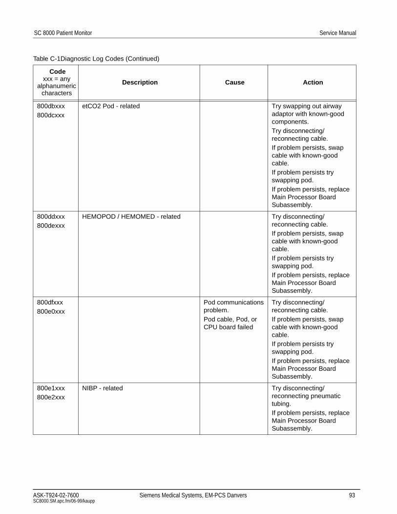
SC 8000 Patient Monitor Service Manual
800dbxxx800dcxxx
etCO2 Pod - related Try swapping out airway adaptor with known-good components.Try disconnecting/reconnecting cable.If problem persists, swap cable with known-good cable.If problem persists try swapping pod.If problem persists, replace Main Processor Board Subassembly.
800ddxxx800dexxx
HEMOPOD / HEMOMED - related Try disconnecting/reconnecting cable.If problem persists, swap cable with known-good cable.If problem persists try swapping pod.If problem persists, replace Main Processor Board Subassembly.
800dfxxx800e0xxx
Pod communications problem.Pod cable, Pod, or CPU board failed
Try disconnecting/reconnecting cable.If problem persists, swap cable with known-good cable.If problem persists try swapping pod.If problem persists, replace Main Processor Board Subassembly.
800e1xxx800e2xxx
NIBP - related Try disconnecting/reconnecting pneumatic tubing.If problem persists, replace Main Processor Board Subassembly.
Table C-1Diagnostic Log Codes (Continued)
Codexxx = any
alphanumeric characters
Description Cause Action
ASK-T924-02-7600 Siemens Medical Systems, EM-PCS Danvers 93 SC8000.SM.apc.fm/06-99/kaupp

Service Manual SC 8000 Patient Monitor
800e5xxx800e6xxx
RESP-related Try disconnecting/reconnecting cable.If problem persists, swap cable with known-good cable.If problem persists try swapping pod.If problem persists, replace Main Processor Board Subassembly
800e7xxx SPO2 - related Try disconnecting/reconnecting cable.If problem persists, try replacing sensor.If problem persists, swap cable with known-good cable.If problem persists try swapping pod.If problem persists, replace Main Processor Board Subassembly.
800e9xxx800eaxxx
Temperature - related (MultiMed Pod) Try disconnecting/reconnecting cable.If problem persists, swap cable with known-good cable.If problem persists try swapping pod.If problem persists, replace Main Processor Board Subassembly.
800f1xxx800f2xxx
Temperature - related (MultiMed Pod) Try disconnecting/reconnecting cable.If problem persists, swap cable with known-good cable.If problem persists try swapping pod.If problem persists, replace Main Processor Board Subassembly
Table C-1Diagnostic Log Codes (Continued)
Codexxx = any
alphanumeric characters
Description Cause Action
94 Siemens Medical Systems, EM-PCS, Danvers ASK-T924-02-7600SC8000.SM.apc.fm/06-99/kaupp
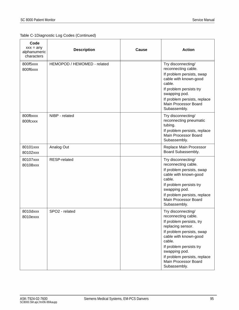
SC 8000 Patient Monitor Service Manual
800f5xxx800f6xxx
HEMOPOD / HEMOMED - related Try disconnecting/reconnecting cable.If problem persists, swap cable with known-good cable.If problem persists try swapping pod.If problem persists, replace Main Processor Board Subassembly.
800fbxxx800fcxxx
NIBP - related Try disconnecting/reconnecting pneumatic tubing.If problem persists, replace Main Processor Board Subassembly.
80101xxx80102xxx
Analog Out Replace Main Processor Board Subassembly.
80107xxx80108xxx
RESP-related Try disconnecting/reconnecting cable.If problem persists, swap cable with known-good cable.If problem persists try swapping pod.If problem persists, replace Main Processor Board Subassembly.
8010dxxx8010exxx
SPO2 - related Try disconnecting/reconnecting cable.If problem persists, try replacing sensor.If problem persists, swap cable with known-good cable.If problem persists try swapping pod.If problem persists, replace Main Processor Board Subassembly.
Table C-1Diagnostic Log Codes (Continued)
Codexxx = any
alphanumeric characters
Description Cause Action
ASK-T924-02-7600 Siemens Medical Systems, EM-PCS Danvers 95 SC8000.SM.apc.fm/06-99/kaupp

Service Manual SC 8000 Patient Monitor
80117xxx80118xxx
Serial Interface to Remote Keypad - related
Try disconnecting/reconnecting keypad.If problem persists, swap cable with known-good keypad.If problem persists, replace Main Processor Board Subassembly.
80119xxx8011axxx
Temperature - related (MultiMed Pod) Try disconnecting/reconnecting cable.If problem persists, swap cable with known-good cable.If problem persists try swapping pod.If problem persists, replace Main Processor Board Subassembly.
80127xxx80128xxx
bkg_operational determined MONITORING SW is corrupt.
Background entity determined that the Main Software was corrupted (BAD CRC)
Try upgrading SW to currently released version.If error persists, replace Main Processor Board Subassembly.
8012901e boot_validate_download_card could not open/close one of the boot files.
Software memory card may have been removed during a download or the card may have become corrupted
Re-download monitor software. If problem persists, replace memory card.
8014bxxx8014cxxx
RECORDINGS - related Try disconnecting/reconnecting cable.If problem persists, swap cable with known-good cable.If problem persists try swapping Recorder.If problem persists, replace Main Processor Board Subassembly.
8016a00a Image checksum test failed due to TAXI error!
Bad memory/access/fetch
Restart monitor. If error persists replace monitor.
Table C-1Diagnostic Log Codes (Continued)
Codexxx = any
alphanumeric characters
Description Cause Action
96 Siemens Medical Systems, EM-PCS, Danvers ASK-T924-02-7600SC8000.SM.apc.fm/06-99/kaupp

SC 8000 Patient Monitor Service Manual
80179xxx8017axxx
Pod communications problem.Pod cable, Pod, or CPU board failed
Try disconnecting/reconnecting cable.If problem persists, swap cable with known-good cable.If problem persists try swapping pod.If problem persists, replace Main Processor Board Subassembly
8017fxxx80180xxx
Temperature -related (MultiMed Pod) Try disconnecting/reconnecting cable.If problem persists, swap cable with known-good cable.If problem persists try swapping pod.If problem persists, replace Main Processor Board Subassembly
80187020 Error Log was cleared! Manual clear of error log via system console menu
None
8018bxxx8018cxxx
etCO2 Pod - related Try swapping out airway adaptor with known-good components.Try disconnecting/reconnecting cable.If problem persists, swap cable with known-good cable.If problem persists try swapping pod.If problem persists, replace Main Processor Board Subassembly.
8018d005 sn A, status B etCO2 Hardware Fail Replace etCO2 Pod.
8018fxxx80190xxx
Try upgrading SW to currently released version.If error persists, replace Main Processor Board Subassembly.
Table C-1Diagnostic Log Codes (Continued)
Codexxx = any
alphanumeric characters
Description Cause Action
ASK-T924-02-7600 Siemens Medical Systems, EM-PCS Danvers 97 SC8000.SM.apc.fm/06-99/kaupp

Service Manual SC 8000 Patient Monitor
80196006 Chip timed out at: A wrote: B, read: C Flash memory failed tests when doing a download. Bit one is always on.
Re-download software. If problem persists then replace Main Processor Board Subassembly .
8019601d Flash program write verify failed at A. wrote: B, read: C
Monitor flash failed tests when doing a download
Re-download software. If problem persists, replace Main Processor Board Subassembly.
8019700c time=A Heart blip not showing; most likely due to rapid screen re-draws
Ignore
80199xxx8019axxx
PCMCIA Interface - related Retry download. If error persists, return card.
801ac00b Pod Type A Conn B, S/N=C, event D state E
Pod would not power on or off. Connector number in description string are: 1,2,3-hemo pod 4-reserved 5-etCO2
Check/replace in this order pod/cartrige, cable, Main Processor Board Subassembly.
801ac00c Pod Type A, Conn B, S/N=C, event D state E
Comm error, CRC error
If problem persists, check connector or replace pod
801adxxx801aexxx
Try upgrading SW to currently released version.If error persists, replace Main Processor Board Subassembly.
801b7000 ERROR: load_34010 34010 Failure Replace Main Processor Board Subassembly
801b7001 ERROR: load_34010 34010 Failure Replace Main Processor Board Subassembly.
801c9xxx801caxxx
RECORDINGS - related Try disconnecting/reconnecting cable.If problem persists, swap cable with known-good cable.If problem persists try swapping Recorder.If problem persists, replace Main Processor Board Subassembly.
Table C-1Diagnostic Log Codes (Continued)
Codexxx = any
alphanumeric characters
Description Cause Action
98 Siemens Medical Systems, EM-PCS, Danvers ASK-T924-02-7600SC8000.SM.apc.fm/06-99/kaupp

SC 8000 Patient Monitor Service Manual
801e1xxx801e2xxx
HEMOPOD / HEMOMED - related Try disconnecting/reconnecting cable.If problem persists, swap cable with known-good cable.If problem persists try swapping pod.If problem persists, replace Main Processor Board Subassembly.
801e7xxx801e8xxx
Try upgrading SW to currently released version.If error persists, replace Main Processor Board Subassembly.
8020fxxx80210xxx
Software did not allocate enough memory for user’s current setup.
Try disabling items connected or disabling Auto Dual View.If error persists, try upgrading SW to currently released version.If error persists, replace Main Processor Board Subassembly.
80231005 LCOM_BAD_SWITCH_COUNT_ERROR
Comm error This indicates a SW error and should be reported to Customer service via DataCard.
8023100a LCOM_CHECKSUM_DIAG_ERROR Comm error This indicates a SW error and should be reported to Customer service via DataCard.
8023102b LCOM_RAM_DIAG_ERROR Net comm failure This indicates a SW error and should be reported to Customer service via DataCard.
8023102c LCOM_ROM_DIAG_ERROR Net comm failure This indicates a SW error and should be reported to Customer service via DataCard.
Table C-1Diagnostic Log Codes (Continued)
Codexxx = any
alphanumeric characters
Description Cause Action
ASK-T924-02-7600 Siemens Medical Systems, EM-PCS Danvers 99 SC8000.SM.apc.fm/06-99/kaupp

Service Manual SC 8000 Patient Monitor
8023102e LCOM_SHRAM_CHECKSUM_ERROR Net comm failure This indicates a SW error and should be reported to Customer service via DataCard.
80231030 LCOM_SHRAM_DIAG_ERROR Net comm failure This indicates a SW error and should be reported to Customer service via DataCard.
80231031 LCOM_SHRAM_PACKET_ERROR Net comm failure This indicates a SW error and should be reported to Customer service via DataCard.
80231032 LCOM_SHRAM_PRL_ERROR net comm failure This indicates a SW error and should be reported to Customer service via DataCard.
8023dxxx8023exxx80249xxx8024axxx
PCMCIA Interface - related Retry download. If error persists, return card.
80255xxx80256xxx
Try upgrading SW to currently released version.If error persists, replace Main Processor Board Subassembly.
8025bxxx8025cxxx80263xxx80264xxx
RS-232 Output - related Ignore.If problem persists, replace Main Processor Board Subassembly.
80264001 Invalid status after RX_RESET! rx_data=A
Recorder ASIC failed hardware test
Power cycle unit. If error persists, replace Main Processor Board Subassembly.
80264002 TX Empty should be set after TX_RESET! tx_data=A
Recorder ASIC failed cold start test
Power cycle unit. If error persists, replace Main Processor Board Subassembly.
Table C-1Diagnostic Log Codes (Continued)
Codexxx = any
alphanumeric characters
Description Cause Action
100 Siemens Medical Systems, EM-PCS, Danvers ASK-T924-02-7600SC8000.SM.apc.fm/06-99/kaupp

SC 8000 Patient Monitor Service Manual
8026dxxx8026exxx
Network Communications - related Try disconnecting/reconnecting cable between Monitor and network wallbox.Verify proper SW version(s) installed in all related devices, in accordance with SW compatibility chart for Monitor SW.If problem persists, replace Main Processor Board Subassembly.
80271xxx80272xxx
Network Communications - related Try disconnecting/reconnecting cable between Monitor and network wallbox.Verify proper SW version(s) installed in all related devices, in accordance with SW compatibility chart for Monitor SW.If problem persists, replace Main Processor Board Subassembly.
80273xxx80274xxx
NIBP - related Try disconnecting/reconnecting pneumatic tubing.If problem persists, replace Main Processor Board Subassembly.
8027dxxx8027exxx
Network Communications - related Try disconnecting/reconnecting cable between Monitor and network wallbox.Verify proper SW version(s) installed in all related devices, in accordance with SW compatibility chart for Monitor SW.If problem persists, replace Main Processor Board Subassembly.
Table C-1Diagnostic Log Codes (Continued)
Codexxx = any
alphanumeric characters
Description Cause Action
ASK-T924-02-7600 Siemens Medical Systems, EM-PCS Danvers 101 SC8000.SM.apc.fm/06-99/kaupp
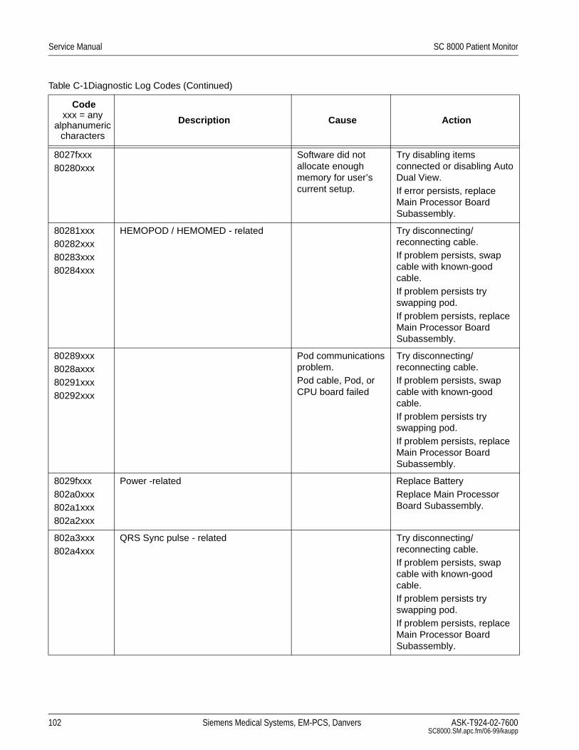
Service Manual SC 8000 Patient Monitor
8027fxxx80280xxx
Software did not allocate enough memory for user’s current setup.
Try disabling items connected or disabling Auto Dual View.If error persists, replace Main Processor Board Subassembly.
80281xxx80282xxx80283xxx80284xxx
HEMOPOD / HEMOMED - related Try disconnecting/reconnecting cable.If problem persists, swap cable with known-good cable.If problem persists try swapping pod.If problem persists, replace Main Processor Board Subassembly.
80289xxx8028axxx80291xxx80292xxx
Pod communications problem.Pod cable, Pod, or CPU board failed
Try disconnecting/reconnecting cable.If problem persists, swap cable with known-good cable.If problem persists try swapping pod.If problem persists, replace Main Processor Board Subassembly.
8029fxxx802a0xxx802a1xxx802a2xxx
Power -related Replace BatteryReplace Main Processor Board Subassembly.
802a3xxx802a4xxx
QRS Sync pulse - related Try disconnecting/reconnecting cable.If problem persists, swap cable with known-good cable.If problem persists try swapping pod.If problem persists, replace Main Processor Board Subassembly.
Table C-1Diagnostic Log Codes (Continued)
Codexxx = any
alphanumeric characters
Description Cause Action
102 Siemens Medical Systems, EM-PCS, Danvers ASK-T924-02-7600SC8000.SM.apc.fm/06-99/kaupp

SC 8000 Patient Monitor Service Manual
802abxxx802acxxx802adxxx802aexxx
RECORDINGS - related Try disconnecting/reconnecting cable.If problem persists, swap cable with known-good cable.If problem persists try swapping Recorder.If problem persists, replace Main Processor Board Subassembly.
802b9xxx802baxxx
RESP-related Try disconnecting/reconnecting cable.If problem persists, swap cable with known-good cable.If problem persists try swapping pod.If problem persists, replace Main Processor Board Subassembly
802bbxxx802bcxxx
Try upgrading SW to currently released version.If error persists, replace Main Processor Board Subassembly.
802bf008 memory partition 2 is 91 percent used. Memory utilization note
Ignore
802d4002 shutdown not due to user. Could be low battery.
Monitor was shut down without using the user’s front panel switch. Usually this means that the monitor was running on internal batteries and ran out of power.
If runing monitor on internal battery, ignore this message. Otherwise report condition to customer service
Table C-1Diagnostic Log Codes (Continued)
Codexxx = any
alphanumeric characters
Description Cause Action
ASK-T924-02-7600 Siemens Medical Systems, EM-PCS Danvers 103 SC8000.SM.apc.fm/06-99/kaupp

Service Manual SC 8000 Patient Monitor
802dfxxx802e0xxx
SPO2 - related Try disconnecting/reconnecting cable.If problem persists, try replacing sensor.If problem persists, swap cable with known-good cable.If problem persists try swapping pod.If problem persists, replace Main Processor Board Subassembly.
802e701c Powering up the System... Power was turned on. Ignore
802e701d Indicates that new software was installed
No action nessessary
802ef011 trends completely cleared, new sofware loaded
Software warning Ignore
802f1xxx802f2xxx
Network Communications - related Try disconnecting/reconnecting cable between Monitor and network wallbox.Verify proper SW version(s) installed in all related devices, in accordance with SW compatibility chart for Monitor SW.If problem persists, replace Main Processor Board Subassembly.
8030500d b A a=B w=C d=D 0 e=E 0 s=F rx=G ok=H flags=I df=J,K
SW error Replace Main Processor Board Subassembly.
80309xxx8030axxx
Try upgrading SW to currently released version.If error persists, replace Main Processor Board Subassembly.
Table C-1Diagnostic Log Codes (Continued)
Codexxx = any
alphanumeric characters
Description Cause Action
104 Siemens Medical Systems, EM-PCS, Danvers ASK-T924-02-7600SC8000.SM.apc.fm/06-99/kaupp

SC 8000 Patient Monitor Service Manual
80311xxx80312xxx
Network Communications - related Try disconnecting/reconnecting cable between Monitor and network wallbox.Verify proper SW version(s) installed in all related devices, in accordance with SW compatibility chart for Monitor SW.If problem persists, replace Main Processor Board Subassembly.
80325001 Speaker Out of Range value: A Failed speaker, CPU board or front panel board
If sound is heard replace Connector I/O Board. Otherwise, replace Main Processor Board Subassembly
80359xxx8035axxx
Network Communications - related Try disconnecting/reconnecting cable between Monitor and network wallbox.Verify proper SW version(s) installed in all related devices, in accordance with SW compatibility chart for Monitor SW.If problem persists, replace Main Processor Board Subassembly.
8035bxxx8035cxxx
Serial Interface to Remote Keypad - related
Try disconnecting/reconnecting keypad.If problem persists, swap cable with known-good keypad.If problem persists, replace Main Processor Board Subassembly.
Table C-1Diagnostic Log Codes (Continued)
Codexxx = any
alphanumeric characters
Description Cause Action
ASK-T924-02-7600 Siemens Medical Systems, EM-PCS Danvers 105 SC8000.SM.apc.fm/06-99/kaupp

Service Manual SC 8000 Patient Monitor
8035dxxx8035exxx8036fxxx80370xxx
Network Communications - related Try disconnecting/reconnecting cable between Monitor and network wallbox.Verify proper SW version(s) installed in all related devices, in accordance with SW compatibility chart for Monitor SW.If problem persists, replace Main Processor Board Subassembly.
80371xxx80372xxx
MGM - related Verify proper SW version(s) installed in all related devices, in accordance with SW compatibility chart for Monitor SW.If problem persists, try disconnecting/reconnecting cable(s) between Monitor and MGM.If problem persists,try replacing cable(s) between Monitor and MGM.If problem persists, try swapping MGM with known-good device.If problem persists try replacing MIB 1&2 Option.If problem persists, replace Main Processor Board Subassembly.
Table C-1Diagnostic Log Codes (Continued)
Codexxx = any
alphanumeric characters
Description Cause Action
106 Siemens Medical Systems, EM-PCS, Danvers ASK-T924-02-7600SC8000.SM.apc.fm/06-99/kaupp

SC 8000 Patient Monitor Service Manual
80373xxx80374xxx
MIB - related Verify proper SW version(s) installed in all related devices, in accordance with SW compatibility chart for Monitor SW.If problem persists, try disconnecting/reconnecting cable(s) between Monitor and MIB converter.If problem persists,try replacing cable(s) between Monitor and MIB converter.If problem persists, try swapping MIB converter with known-good device.If problem persists, try replacing MIB 1&2 Option.If problem persists, replace Main Processor Board Subassembly.
80375xxx80376xxx
ISD (SDC) - related Verify proper SW version(s) installed in all related devices, in accordance with SW compatibility chart for Monitor SW.If problem persists, try disconnecting/reconnecting cable(s) between Monitor and ISD (SDC).If problem persists,try replacing cable(s) between Monitor and ISD (SDC).If problem persists, try swapping ISD (SDC) with known-good device.If problem persists, try replacing Adv. Comm Option Subassembly.If problem persists, replace Main Processor Board Subassembly.
Table C-1Diagnostic Log Codes (Continued)
Codexxx = any
alphanumeric characters
Description Cause Action
ASK-T924-02-7600 Siemens Medical Systems, EM-PCS Danvers 107 SC8000.SM.apc.fm/06-99/kaupp
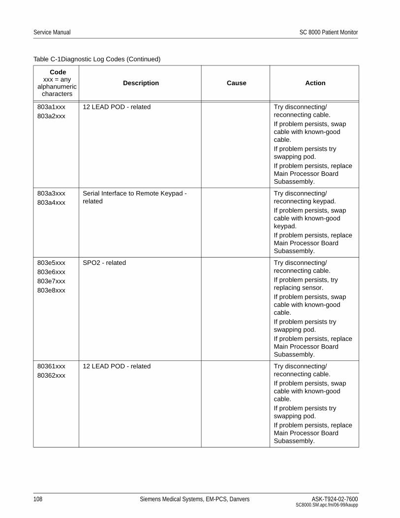
Service Manual SC 8000 Patient Monitor
803a1xxx803a2xxx
12 LEAD POD - related Try disconnecting/reconnecting cable.If problem persists, swap cable with known-good cable.If problem persists try swapping pod.If problem persists, replace Main Processor Board Subassembly.
803a3xxx803a4xxx
Serial Interface to Remote Keypad - related
Try disconnecting/reconnecting keypad.If problem persists, swap cable with known-good keypad.If problem persists, replace Main Processor Board Subassembly.
803e5xxx803e6xxx803e7xxx803e8xxx
SPO2 - related Try disconnecting/reconnecting cable.If problem persists, try replacing sensor.If problem persists, swap cable with known-good cable.If problem persists try swapping pod.If problem persists, replace Main Processor Board Subassembly.
80361xxx80362xxx
12 LEAD POD - related Try disconnecting/reconnecting cable.If problem persists, swap cable with known-good cable.If problem persists try swapping pod.If problem persists, replace Main Processor Board Subassembly.
Table C-1Diagnostic Log Codes (Continued)
Codexxx = any
alphanumeric characters
Description Cause Action
108 Siemens Medical Systems, EM-PCS, Danvers ASK-T924-02-7600SC8000.SM.apc.fm/06-99/kaupp

SC 8000 Patient Monitor Service Manual
803f1xxx803f2xxx803f3xxx803f4xxx
etCO2 Pod - related Try swapping out airway adaptor with known-good components.Try disconnecting/reconnecting cable.If problem persists, swap cable with known-good cable.If problem persists try swapping pod.If problem persists, replace Main Processor Board Subassembly.
ffffffff boot_program_images failed with status: A on image: B
Flash programming error when performing a download
Retry download. If problem persists replace Main Processor PC Board Subassembly.
Table C-1Diagnostic Log Codes (Continued)
Codexxx = any
alphanumeric characters
Description Cause Action
ASK-T924-02-7600 Siemens Medical Systems, EM-PCS Danvers 109 SC8000.SM.apc.fm/06-99/kaupp

Service Manual SC 8000 Patient Monitor
This page intentionally blank.
110 Siemens Medical Systems, EM-PCS, Danvers ASK-T924-02-7600SC8000.SM.apc.fm/06-99/kaupp

SC 8000 Patient Monitor Service Manual
Appendix D: Functional Verification Checklist
Section Reference in “ Chapter 4: Functional Verification and Calibration ” G = Test Passed
3 Power Circuits and Start-up (page 49) _______
3.1 Power ON/OFF key _______• Power LED _______
• Piezo tone _______
3.2 Power-Up Sequence _______
3.3 Monitor Powered By External Source _______
4 Rotary Knob (page 49) _______
• Pointing Function _______
• Selecting Function _______
5 LCD Display (page 49) _______
• Inoperative pixels within spec _______
• Brightness control _______
• Backlite illumination _______
6 Fixed Keys (page 49) _______
6.1 ON/OFF _______
6.2 Main Screen _______
6.3 Alarm Silence _______
6.4 Alarm Limits _______
6.5 All Alarms Off _______
6.6 Code _______
6.7 Record _______
6.8 Print Screen _______
6.9 NBP Start/Stop _______
6.10 Zoom _______
6.11 Help _______
6.12 Mark _______
7 ECG/RESP Functions (page 51) _______
7.2 Waveforms/Digital Readouts/Tones _______
7.3 Pacer Detection _______
7.4 Lead-Off Indicators _______
7.5 Alarm Function _______
7.6 Asystole _______
ASK-T924-02-7600 Siemens Medical Systems, EM-PCS Danvers 111 SC8000.SM.apd.fm/06-99/kaupp

Service Manual SC 8000 Patient Monitor
8 SpO2 Function (page 53) _______
8.2 Waveforms/Digital Readouts/Tones _______
8.3 Pulse Tone Generator _______
8.4 Limits Alarm _______
9 Temperature Function (page 54) (MultiMed POD) _______
9.2 Digital Readout Temp A _______Temp B ________
9.3 Temperature Calibration _______
10Non-Invasive Blood Pressure Function (page 54) _______
10.2 (or 10.3) Calibration OK _______
10.4 Hardware Overpressure _______
10.5 Pump _______
10.6 Interval Mode _______
10.7 Safety Timer _______
11etCO2 Function (page 57) _______
• Sensor Cal. _______
• Sensor Zero _______
• Measured Value w/ Manual Atm. Press. _______
• Measured Value w/ AUTO Atm. Press. _______
12HemoMed Pod (page 58) _______
12.1 Invasive Blood Pressure Function _______
12.1.2 HEMO Channel A (Aux./Hemo3 input)
• Monitor Zero Function _______
• Monitor Pressure Reading _______
12.1.2 HEMO Channel A (Aux./Hemo2 input)
• Monitor Zero Function _______
• Monitor Pressure Reading _______
12.1.2 HEMO POD Channel B _______
12.1.2 HEMO POD Channel C _______
12.1.2 HEMO POD Channel D _______
12.2 Cardiac Output Function _______• Blood temperature ______
• Injectate temp ______
13HEMO POD2/4 (page 60) _______
13.1 Invasive Blood Pressure Function _______
13.1.2 HEMO Channel A (Aux./Hemo3 input)
• Monitor Zero Function _______
• Monitor Pressure Reading _______
112 Siemens Medical Systems, EM-PCS, Danvers ASK-T924-02-7600SC8000.SM.apd.fm/06-99/kaupp

SC 8000 Patient Monitor Service Manual
13.1.2 HEMO Channel A (Aux./Hemo2 input)
• Monitor Zero Function _______
• Monitor Pressure Reading _______
13.1.2 HEMO POD Channel B _______
13.1.2 HEMO POD Channel C _______
13.1.2 HEMO POD Channel D _______
13.2 Temperature Function _______• T1a _______
• T1b _______
• _______
13.3 Cardiac Output Function _______• Blood temperature ______
• Injectate temp ______
14Memory Backup (page 62) _______
15MIB 1&2 and CAN Options (if installed) (page 62) _______
• CAN Option _______
• MIB 1&2 Option _______
16Adv Comm Option (if installed) (page 62) _______
17Configuration (page 63) _______
18Battery Charger Circuit (page 63) _______
19Recorder Function (page 63) _______
20LeakageTests (page 63) _______
20.1 Resistance TestResistance Reading (Ω _________
20.2 Leakage Current Tests(QFORVXUH&DVH
/HDNDJH&XUUHQW
1RUPDO _________
2SHQ*URXQG
#YDF BBBBBBBBB
RU #YDF BBBBBBBBB
2SHQ*URXQGDQG5HYHUVH0DLQV
#YDF BBBBBBBBB
RU #YDF BBBBBBBBB
3DWLHQW&RPELQHG
/HDNDJH&XUUHQW
1RUPDO _________
2SHQ*URXQG _________
/HDNDJHZLWK0DLQVRQ
3DWLHQW/HDGVBBBBBBBBB
∆T1
ASK-T924-02-7600 Siemens Medical Systems, EM-PCS Danvers 113 SC8000.SM.apd.fm/06-99/kaupp

Service Manual SC 8000 Patient Monitor
Clinical Site Report
Clinical Site Name: Date:
Address:
_______________________________________Clinical Site Facility Manager:
_______________________________________Clinical Site Contact Person:
Tel. No: FAX No. Int’l Code Number Ext:
Monitoring Unit _______________________________
Care Unit _________________
Monitor Serial No. _________________________
Monitor has passed all required tests.
Siemens Service Representative:
_____________________________________________________________________ ________________Name (Print) Signature Date
Clinical Site Representative:
_____________________________________________________________________ ________________Name (Print) Signature Date
114 Siemens Medical Systems, EM-PCS, Danvers ASK-T924-02-7600SC8000.SM.apd.fm/06-99/kaupp

SC 8000 Patient Monitor Service Manual
Appendix E: Service Setup Instructions ,QWURGXFWLRQ 6&0RQLWRUVDUHVKLSSHGZLWKVRIWZDUHLQVWDOOHG&HUWDLQVHUYLFH
SDVVZRUGSURWHFWHGIXQFWLRQVLQWKHPRQLWRUKRZHYHUQHHGWREHVHWIRU
WKHVSHFLILFFXVWRPHUVLWH$OVRLIWKHPRQLWRULVWREHXVHGLQDQ,1),1,7<
1(7:25.HQYLURQPHQWWKHPRQLWRUQHHGVWREHFRQILJXUHGWRFRPPXQLFDWH
SURSHUO\LQWKHQHWZRUN
,QLWLDO6HWXS 1RWH 7XUQWKHURWDU\NQREWRVHOHFWDILHOGRUPHQXLWHPRUWR
FKDQJHWKHGHIDXOWIRUDVHOHFWHGLWHP3UHVVLQRQWKHNQREWRDFFHVV
DPHQXRUPHQXLWHPRUWRVHWWKHQHZGHIDXOWIRUDVHOHFWHGLWHP
)LUPO\SUHVV212))NH\LQOHIWFRUQHURIIURQWSDQHO
$IWHUWKHPRQLWRUKDVFRPSOHWHGSRZHUXSVHTXHQFHDVLQGLFDWHGE\
LOOXPLQDWLRQRIo1HZ3DWLHQW"pSURPSWSUHVVURWDU\NQREWRVHOHFW
o<HVpDQGEULQJXS0$,1VFUHHQ
6HOHFW0RQLWRU6HWXS→0RQLWRU2SWLRQV→'DWH7LPH
6HW7LPHDQG'DWHDVDSSURSULDWHIRUFXVWRPHUVLWH
3UHVV0HQXNH\WRUHWXUQWR0DLQPHQX
6HOHFW0RQLWRU6HWXS→8QLW0DQDJHU
(QWHU&OLQLFDOSDVVZRUGDQGWKHQVHOHFW0HQX6HWXSRQ8QLW
0DQDJHUPHQX
6HW0HQX7LPH/LPLWWR2))
3UHVV0HQXNH\WRUHWXUQWR0DLQPHQX
$FFHVVLQJ6HUYLFH0HQX 6HOHFW0RQLWRU6HWXS→ %LRPHG→6HUYLFH
(QWHU%LRPHGSDVVZRUG
6HOHFW%HGVLGH6HWXSDQGYHULI\WKHIROORZLQJRUVHWDVUHTXLUHG
q /DQJXDJHVHWWLQJLVDSSURSULDWHIRUFXVWRPHUVLWH
q 5HJXODWLRQLVDSSURSULDWHIRUFXVWRPHUVLWH
q $ODUP6RXQGVVHWWRHLWKHU'HIDXOWRU6LUHFXVWDVSUHIHUUHG
q /LQH)UHTXHQF\LVDSSURSULDWHIRUFXVWRPHUVLWH
q :DYHIRUP6LPXODWRULVVHW2))IRUFOLQLFDOXVHRI0RQLWRU
6HOHFW←LQXSSHUOHIWKDQGFRUQHUWRUHWXUQWRSUHYLRXVPHQX
6HOHFW1HWZRUN'DWHDQG7LPHDQGVHW&XUUHQW'DWHDQG&XUUHQW
7LPHDVDSSURSULDWHIRUFXVWRPHUVLWH
6HOHFW←WRUHWXUQWRSUHYLRXVPHQX
6HOHFW1HWZRUN6HWXSDQGVHWWKHIROORZLQJDVUHTXLUHG
q ,I6&WREHXVHGRQO\LQ6WDQGDORQHPRGHVHW1HWZRUN&RQWURO
WR2))DQGSRZHUF\FOHPRQLWRU9HULI\WKDW0$,1VFUHHQGLVSOD\V
DIWHUFRPSOHWLRQRISRZHUXSVHTXHQFH0RQLWRUVHWXSLVFRPSOHWH
q ,I6&LVWREHFRQQHFWHGWRDQ,1),1,7<1(7:25.6HW1HWZRUN
&RQWUROWR21DQGFRQWLQXH
q o3ULQWHU$GGUHVVpGLVSOD\VWKHIRXUWKRFWHWRIWKH,3DGGUHVVRIWKH
QHWZRUNSULQWHULIDQ\WKDWSULQWVRXW0RQLWRU6HWXS→ %LRPHG→
/RJV→3ULQW/RJUHTXHVWV(QWHUQHWZRUNSULQWHUQXPEHUWRVHWRU
FKDQJHDGGUHVV2WKHUZLVHFRQWLQXH
ASK-T924-02-7600 Siemens Medical Systems, EM-PCS Danvers 115 SC8000.SM.ape.fm/06-99/kaupp

Service Manual SC 8000 Patient Monitor
6HOHFW1HWZRUN&RQILJ
'RHLWKHUDRUEDVUHTXLUHG
1RWH )RUILUVWWLPHGDWDHQWU\LISDUDPHWHUVLQ1HWZRUN&RQILJPHQX
FDQQRWEHVHOHFWHGSOXJQHWZRUNFDEOHLQWRSRUWRQEDFNSDQHO
3RZHUF\FOHPRQLWRU7KHQGLVFRQQHFWQHWZRUNFDEOH
D ,I$GY&RPP2SWLRQLV127LQVWDOOHGVHW1HWZRUN0RGHWR'LUHFW1HWDQGVHOHFW6DYH$//EHIRUHFRQWLQXLQJ
E ,I$GY&RPP2SWLRQLVLQVWDOOHGVHW1HWZRUN0RGHWR&36,'6
7KH$GY&RPP2SWLRQ3&%SHUIRUPVVRPHIXQFWLRQVRIDQ,'6
(QWHUFRQILJXUDWLRQGDWDLQWR7DEOHLQ6HFWLRQ&RQILJXUDWLRQ
3DUDPHWHUVDQGWKHQIROORZSURFHGXUHLQ6HFWLRQWRFRQILJXUH
PRQLWRU
1RWH 6HFWLRQLQFOXGHVDQH[SODQDWLRQRIHDFKSDUDPHWHULQ7DEOH
&RQILJXUDWLRQ3DUDPHWHUV
&RQILJXULQJLVWKHSURFHVVRIDVVLJQLQJDXQLTXHHOHFWURQLFDGGUHVVDQG
YDULRXVDOSKDQXPHULFDGGUHVVHVODEHOVWKDWLGHQWLI\WKHPRQLWRUDQG
HQDEOHLWWRFRPPXQLFDWHZLWKRWKHUGHYLFHVLQDQ,1),1,7<1(7:25.7DEOH
LVDUHSOLFDWLRQRIWKH1HWZRUN&RQILJPHQXIRUGDWDHQWU\LQWKHPRQLWRU
:KHUHDSSOLFDEOHWKHWDEOHOLVWVGHIDXOWYDOXHRUPRVWOLNHO\YDOXH'2
127XVHOHDGLQJ]HURVIRUQXPEHUV
1HWZRUN0RGHVHWDVLQVWHSDERYH$OZD\VVHOHFWo6DYH$//p
EHIRUHFRQWLQXLQJLIFKDQJLQJ1HWZRUN0RGHVHWWLQJ
%HGDXVHUGHILQHGFKDUDFWHUDOSKDQXPHULFILHOGIRUQDPLQJDEHG
HJ,&%('%('/DEHODSSHDUVLQORZHUOHIWKDQGFRUQHURI
0$,1VFUHHQDQGRQ08/7,9,(::25.67$7,21GLVSOD\DQGUHFRUGLQJV
0XVWEHXQLTXHLQ0RQLWRULQJ8QLW
&36,'6DXVHUGHILQHGFKDUDFWHUDOSKDQXPHULFILHOGIRUQDPLQJ
PRQLWRUHJ6&N/DEHODSSHDUVRQ08/7,9,(::25.67$7,21
GLVSOD\LQ6+2:'(9,&(VFUHHQ0XVWEHGLIIHUHQWIURP%HGODEHO
DQGXQLTXHLQ0RQLWRULQJ8QLW
&DUH8QLWODEHORI&DUH8QLWWRZKLFKPRQLWRULVDVVLJQHG
0RQLWRULQJ8QLWODEHORI0RQLWRULQJ8QLWWRZKLFKPRQLWRULVDVVLJQHG
+RVSLWDOODEHOIRUFOLQLFDOVLWHWRZKLFKPRQLWRULVDVVLJQHG
5HFRUGHU5HFRUGHUDQG5HFRUGHU8VH1RWFRQILJXUDEOHLQWKLV
VRIWZDUHYHUVLRQ
+RVW,'DQXPEHUIURPWRQRWDOUHDG\XVHGIRU+RVW,'RI
DQRWKHUGHYLFHLQVDPH0RQLWRULQJ8QLWWRZKLFKPRQLWRULVDVVLJQHG
0RQLWRULQJ8QLW,'QXPEHURI0RQLWRULQJ8QLWWRZKLFKPRQLWRULV
DVVLJQHG
,3DGGUHVV7KLVILHOGXVHVIRUILUVWWZRE\WHV0RQLWRULQJ8QLW,'
IRUWKLUGE\WHDQG+RVW,'IRUIRXUWKE\WH%HVXUH0RQLWRULQJ8QLW
,'LVVHWWRWKHVDPHQXPEHUDVLQVWHS
6XEQHWPDVN8VHGHIDXOWXQOHVVKRVSLWDOUHTXLUHVDGLIIHUHQWYDOXH
'HIDXOWURXWHU8VHGHIDXOWXQOHVVKRVSLWDOUHTXLUHVGLIIHUHQWYDOXH
5HPRWH6LOHQFHW\SHLQ\RUQo\pPHDQVWKH08/7,9,(:
:25.67$7,21FDQVLOHQFHWKHEHGVLGHDODUPoQpPHDQVWKDWDODUP
FDQQRWEHUHPRWHO\VLOHQFHG
116 Siemens Medical Systems, EM-PCS, Danvers ASK-T924-02-7600SC8000.SM.ape.fm/06-99/kaupp

SC 8000 Patient Monitor Service Manual
5HPRWHFRQWUROHQDEOHGW\SHLQ\RUQo\pPHDQVPRQLWRUDOORZV
08/7,9,(::25.67$7,21WRFKDQJHDODUPVVHWXSDQGGHPRJUDSKLFV
LQPRQLWRUoQpPHDQVPRQLWRUFDQQRWEHUHPRWHO\FRQWUROOHGWKURXJK
09:6
$ODUPJURXS$QDODUPJURXSLVDJURXSRIEHGVWKDWPRQLWRU
HDFKRWKHU7KLQNRIWKLVDVEHGWREHGFRPPXQLFDWLRQDVRSSRVHGWR
EHGWR08/7,9,(::25.67$7,21FRPPXQLFDWLRQ%HLQJSDUWRIWKH
VDPHDODUPJURXSDOORZV\RXWRVHHWKHDODUPPHVVDJHVIRUDOOEHGV
LQVDPHDODUPJURXS
&HQWUDO6WDWLRQHQDEOHG\HVRUQR,I\RXFKRRVH\HVWKHEHGVLGH
PRQLWRUH[SHFWVDQDODUPDFNQRZOHGJPHQWIURP08/7,9,(:
:25.67$7,21,ILWGRHVQnWJHWRQHLWJRHVWRLWVKLJKHVWDODUPYROXPH
DQGLQGLFDWHVDQRIIOLQHFRQGLWLRQ
q ,I\RXFKRRVHQRWKHEHGVLGHPRQLWRUGRHVQRWH[SHFWDQ
DFNQRZOHGJPHQWIURP08/7,9,(::25.67$7,21DQGZLOOQRWJRWRLWV
KLJKHVWDODUPYROXPH
q ,IWKHUHLVQR08/7,9,(::25.67$7,21RQWKLV,1),1,7<1(7:25.RU
WKLVEHGLV127WREHFHQWUDOO\PRQLWRUHGFKRRVHo12p
&RQILJXULQJ0RQLWRU 2Q0DLQPHQXDFFHVV0RQLWRU6HWXS→8QLW0DQDJHUDQGHQWHU
&OLQLFDOSDVVZRUG
6HOHFW0HQX6HWXSDQGVHW0HQX7LPH/LPLWWR2))
2Q0DLQPHQXDFFHVV0RQLWRU6HWXS→%LRPHG→6HUYLFHDQG
HQWHU%LRPHGSDVVZRUG
2Q6HUYLFHPHQXVHOHFW1HWZRUN&RQILJ
)RUHDFKSDUDPHWHUHQWHUGDWDIURP7DEOHDQGVHOHFWo$FFHSWp
1RWH )RUQXPHULFDOILHOGVURWDU\NQRELQFUHPHQWVDQGGHFUHPHQWV
QXPEHUVLQWKHILHOGDVZHOODVHQWHUVWKHGDWD
$IWHUDOOGDWDKDVEHHQHQWHUHGUHFKHFNGDWDDQGWKHQVHOHFW6DYH
$//
7DEOH 0RQLWRU&RQILJXUDWLRQ3DUDPHWHUV
1HWZRUN&RQILJ
1HWZRUN0RGH +RVW,' ]
%HG 0RQLWRULQJ8QLW,' \
&36,'6 ,3$GGUHVV \]
&DUH8QLW 6XEQHW0DVN
0RQLWRULQJ8QLW 'HIDXOW5RXWH
+RVSLWDO 5HPRWH6LOHQFH
5HFRUGHU 5HPRWH&RQWURO
5HFRUGHU $ODUP*URXS
5HFRUGHU8VH &HQWUDO6WDWLRQ
6DYH$//
ASK-T924-02-7600 Siemens Medical Systems, EM-PCS Danvers 117 SC8000.SM.ape.fm/06-99/kaupp

Service Manual SC 8000 Patient Monitor
1RWH 0RQLWRUVDYHVDOOHQWULHVDQGWKHQSRZHUF\FOHVLIDQ\,3
DGGUHVVSDUDPHWHUVRU1HWZRUN0RGHZHUHFKDQJHG0HQX7LPH
/LPLWDXWRPDWLFDOO\UHVHWVWR21LIPRQLWRUSRZHUF\FOHV
3RZHUF\FOHPRQLWRUXQOHVVPRQLWRUSRZHUF\FOHGLQVWHS
&RQQHFWPRQLWRUWRQHWZRUNDQGYHULI\RQ09:6WKDWPRQLWRU
FRPPXQLFDWHVZLWK09:6DQGFRQILJXUDWLRQFRQWDLQVQRGXSOLFDWH
QDPHV
7KLVFRPSOHWHVPRQLWRUVHWXS
118 Siemens Medical Systems, EM-PCS, Danvers ASK-T924-02-7600SC8000.SM.ape.fm/06-99/kaupp

SC 8000 Patient Monitor Service Manual
If procedures in this Manual are performed by other than Siemens service personnel, for more information contact your local Siemens service representative. Technical support for Siemens service personnel is available as follows:
In North and South America: In Europe, Asia, Africa, Australia, and New Zealand:
Siemens Medical Systems, Inc. Siemens-Elema AB
EM-PCS EM
Technical Support and Services Technical Support and Services
16 Electronics Avenue 171 95 Solna, Sweden
Danvers, MA 01923 USA
Tel: (978) 907-7500 Tel: Int+46-8-730-7641
FAX (978) 907-7546 FAX: Int+46-8-986 662
ASK-T924-02-7600 Siemens Medical Systems, EM-PCS Danvers SC8000.SM.bkcvr.fm/06-99/kaupp

SC 8000 Patient Monitor - Service ManualOrder No. 59 54 529 E549U©Siemens - Elema AB, 1999. Electromedical Systems Division. All rights reserved. No part of this publication may be reproduced, stored in a retrieval system, or transmitted in any form or by any means, electronic, mechanical, photocopying, recording, or otherwise, without the prior permission of the copyright owner in writing.Subject to alterations without prior notice.Issued by Siemens Medical Systems, EM-PCS, 16 Electronics Ave., Danvers, MA 02193, U.S.A.
ASK-T924-02-7600E331.E549U.719.10.01.02
Printed in U.S.A.
TU 0999 0.251st English CD-ROM, September 1999