sc-106 september 3, 2013 description and installation … · 2 features the components are...
TRANSCRIPT

1
®
IMPORTANT NOTEThe information provided in this bulletin is directed to competent boiler and combustion servicetechnicians who are experienced in the installation and operation of Fireye Flame Safety equipment.Persons not familiar with Fireye products should contact the nearest Fireye representative or otherqualified service group.
The 55UV5 scanners as well as all other Fireye scanners, are designed to be used exclusively withthe appropriate Fireye Flame Safeguard and Burner Management controls. The application of thesescanners to other than Fireye equipment should be reviewed for approval by Fireye.
APPLICATIONFireye 55UV5 self-checking scanners are used to detect ultraviolet emissions from fossil fuel flamessuch as natural gas, coke oven gas, propane, methane, butane, kerosene, light petroleum distillatesand diesel fuels and are suitable for use in Class I, Div. 2, Groups A, B, C, D and Class II, Div. 2Groups F and G hazardous locations. These 55UV5 models are used only with the BurnerLogix,Flame-Monitor, D-Series, FlameWorx and MicroM control models to provide flame safeguard andmonitoring systems for supervised manual, semi-automatic and fully automatic single burner boil-ers, process ovens and heaters.
PRINCIPLES OF OPERATIONThe 55UV5 scanners use a UV-eye detector. This detector is a sealed, gas filled, UV-sensitive tubecontaining two electrodes connected to a source of AC voltage. When UV radiation of sufficientenergy falls upon the electrodes, electrons are released and the inter-electrode gas becomes conduc-tive, resulting in an electric current flow from one electrode to the other. The current flow starts andends abruptly and is known as an “avalanche.”
A very intense source of UV radiation will produce several hundred avalanches or pulses per second.With less radiation there will be fewer pulses per second. Upon total disappearance of flame, thedetector output ceases. Thus, the presence or absence of pulses is an indication of the presence orabsence of flame; the frequency of the pulses is a measure of flame intensity. Pulses generated by thescanner are transmitted to a compatible Fireye control via scanner wiring.
DESCRIPTIONAND
INSTALLATION
UV self-checking Scanner Models:55UV5-1007, 55UV5-1009
For use only with designated Fireye® controlsFor Infrared Photocell Scanners use SC103
For non self-checking UV Scanners use SC102
SC-106SEPTEMBER 3, 2013
APPROVED
NEMA 4X, IP66CLASS I, DIV 2, GROUPS A, B, C, DCLASS II, DIV 2, GROUPS F and G

2
FEATURESThe components are contained in a cast aluminum NEMA 4X, IP66 housing sealed with an oil-resis-tant gasket. The quartz lens is a planoconvex design, resulting in increased sensitivity. Also includedin the scanner is an electromagnetic shutter that permits a self-checking circuit to verify that thescanner and signal circuits are producing valid flame presence or absence information. During theshutter closed period, the detector’s optical path is blocked from flame radiation, allowing the con-trol system to verify the proper operation of the ultraviolet tube. While the shutter is open, flamepresence or absence is detected.
SPECIFICATIONS
FIGURE 1. DIMENSIONS
SPECIFICATIONS TABLE
NOTE 1: In non-hazardous locations the maximum operating temperature is 199°F (93°C).
NOTE 2: Flame-Monitor, EUVS4; D-Series, 72DUVS1T, 72DUVS4; MicroM, MEUVS1, MEUVS4; FlameWorx; MBUVS-301D,MBUVS-311D; BurnerLogix, YB110UVSC, YB230UVSC.
SPECIFICATIONS
MECHANICAL:
Housing Material: Cast aluminum with grey epoxy coat finish
Housing Weight: 4 lbs (2kg)
Environmental: NEMA 4X, IP66
Hazardous Classifications: Class I, Div. 2, Groups A, B, C, DClass II, Div. 2, Groups F and G
Temperature rating T6 at 140°F (60°C) ambient
MODEL NO. THREADS NOMINAL SHUTTER TOTAL CYCLE PERIOD
VOLTAGE 50/60 HZ TEMP. RANGESee note 1
USE ONLY WITH CONTROL MODELS
TERMINALS
SHUTTER(BLK-WHT)
SIGNAL (BLU-YEL)
MAX. MIN. SIGNAL SHUTTER
55UV5- 1007 1" BSP 0.4 sec. closed3.6 sec. open
102-264VAC 560VAC 140 F60 C
- 40 F(- 40 C)
See note 2 S1-S2 L1-L2
55UV5- 1009 1" NPT 0.4 sec. closed3.6 sec. open
102-264VAC 560VAC 140 F60 C
- 40 F(- 40 C)
See note 2 S1-S2 L1-L2
55UV5-1009FLAME SCANNER
(60-2815-5)INPUT POWER: 102-264VAC. 50/60Hz @0.02 A
AMBIENT TEMPERATURE: -40¡C (-40¡F) TO =65¡C (=150¡F)
CLASS I, DIV.2, GROUPS A, B, C, & D
CLASS II, DIV.2, GROUPS F & G
IP66 NEMA 4X
FIREYEDERRY, NEW DERRY
MADE IN USA
®
FMAPPROVED
TYPE 55UV5
4.87" (123.67mm)
3.93" (99.82mm)
4.74" (120.4mm)
7.39" (187.58mm)
2.07" (52.45mm)
1.18" (29.85mm)
1" NPT (1" BSP) THREAD
3/4" NPT (3/4" BSP) THREAD
0.2" (6mm)
MODEL 1009
3
®
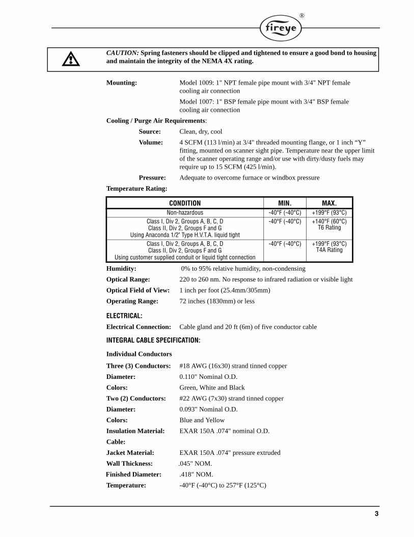
CAUTION: Spring fasteners should be clipped and tightened to ensure a good bond to housing and maintain the integrity of the NEMA 4X rating.
Mounting: Model 1009: 1" NPT female pipe mount with 3/4" NPT femalecooling air connection
Model 1007: 1" BSP female pipe mount with 3/4" BSP femalecooling air connection
Cooling / Purge Air Requirements:
Source: Clean, dry, cool
Volume: 4 SCFM (113 l/min) at 3/4" threaded mounting flange, or 1 inch “Y” fitting, mounted on scanner sight pipe. Temperature near the upper limitof the scanner operating range and/or use with dirty/dusty fuels mayrequire up to 15 SCFM (425 l/min).
Pressure: Adequate to overcome furnace or windbox pressure
Temperature Rating:
Humidity: 0% to 95% relative humidity, non-condensing
Optical Range: 220 to 260 nm. No response to infrared radiation or visible light
Optical Field of View: 1 inch per foot (25.4mm/305mm)
Operating Range: 72 inches (1830mm) or less
ELECTRICAL:
Electrical Connection: Cable gland and 20 ft (6m) of five conductor cable
INTEGRAL CABLE SPECIFICATION:
Individual Conductors
Three (3) Conductors: #18 AWG (16x30) strand tinned copper
Diameter: 0.110" Nominal O.D.
Colors: Green, White and Black
Two (2) Conductors: #22 AWG (7x30) strand tinned copper
Diameter: 0.093" Nominal O.D.
Colors: Blue and Yellow
Insulation Material: EXAR 150A .074" nominal O.D.
Cable:
Jacket Material: EXAR 150A .074" pressure extruded
Wall Thickness: .045" NOM.
Finished Diameter: .418" NOM.
Temperature: -40°F (-40°C) to 257°F (125°C)
CONDITION MIN. MAX.Non-hazardous -40°F (-40°C) +199°F (93°C)
Class I, Div 2, Groups A, B, C, DClass II, Div 2, Groups F and G
Using Anaconda 1/2" Type H.V.T.A. liquid tight
-40°F (-40°C) +140°F (60°C)T6 Rating
Class I, Div 2, Groups A, B, C, DClass II, Div 2, Groups F and G
Using customer supplied conduit or liquid tight connection
-40°F (-40°C) +199°F (93°C)T4A Rating

4
AGENCY CERTIFICATIONSUnderwriters Laboratory: MCCZ2, File MP1537
Controls, Primary Safety - Component
MCCZ8, File MP1537Controls, Primary Safety Certified for Canada
Factory Mutual: Approved, FM class 7610 and 3611
ORDERING INFORMATION
SCANNER MOUNTINGThe 55UV5 scanner is provided with a male connector located in the scanner electronics and twoalignment pin and a female connector located in the front mount.
For ease of installation, it is recommended that the scanner front mount be installed to the burnersight pipe separately.
To remove the scanner electronics from the front mount first remove the two locking bracket clipsfrom the quarter turn latches. Turn the quarter turn latches to disengage the scanner electronics fromthe front mount. Pull the scanner electronics away from the front mount. To re-install, reverse theprocedure.
To maintain compliance, it is necessary to re-install the locking bracket clips.
FIGURE 2.
PART NUMBER DESCRIPTION
55UV5-1007 UV self-check scanner, NEMA 4X, IP66, meets Class I, Div. 2, Groups A, B, C, D and Class II, Div. 2 Groups F and G. Scanner head is 1” BSP with 3/4” BSP purge hole, 20 foot cable and liquid tight connector.
55UV5-1009 UV self-check scanner, NEMA 4X, IP66, meets Class I, Div. 2, Groups A, B, C D and Class II, Div. 2 Groups F and G. Scanner head is 1” NPT with 3/4” NPT purge hole, 20 foot cable and liquid tight connector.
61-7074-3 Replacement, front mount, 1” NPT, 3/4” NPT purge hole, 20 foot cable, liquid tight fitting.
61-7074-4 Replacement, front mount, 1” BSP, 3/4” BSP purge hole, 20 foot cable, liquid tight fitting.
60-2815-5 Replacement, UV self-check scanner electronics assembly, 55UV5-1009 Series
60-2815-6 Replacement, UV self-check scanner electronics assembly, 55UV5-1007 Series
4-314-1 UV tube
61-7075-1 Shutter replacement assembly
SCANNER ELECTRONICS
LOCKING BRACKET CLIP
1" NPT or 1" BSP
QUARTER TURN LATCH
SCANNER FRONT MOUNT

5
®
SCANNER WIRINGAll FIREYE controls are protected against short-circuited scanner input terminals. The following recommendations apply for scanner control wiring:
• Do not run scanner cables in the same conduit as other electrical wires.
• Avoid wire loops and poor groundings.
• Keep high voltage ignition wires well away from scanner wires.
CAUTION: REMOVE ALL POWER BEFORE SERVICING
Scanner Connections:
1. Selection of wire
— Use #14, 16, or 18 wire with 75 C, 600 volt insulation for up to 100 foot distances (signal lossapproximately 20% at 100 feet).
— Asbestos insulated wire should be avoided.
— Multiconductor cable is not recommended without prior factory approval.
— Extended Scanner Wiring. For extended scanner wiring up to 1500 feet, and for shorterlengths to reduce signal loss, use a shielded wire (Belden 8254-RG62U) coaxial cable, orequal for each blue and yellow wire of the 55UV5. The ends of the shielding must be tapedindividually on both ends and not grounded.
For multiple burner installations:
2. Distances are decreased when more than one set of scanner leads are installed in a common con-duit. For example, the maximum distance for 2 scanners is 750 feet and for 3 or more scannersthe distance decreases to 500 feet.
3. High voltage ignition wiring should not be installed in the same conduit with flame detectorwires.
Note: When used for a Class I, Div 2 application, the liquid tight flexible conduit (AnacondaSealtight® 1/2" Type H.T.V.A or equivalent, available at any electrical supply outlet) can beinserted over the existing cable. The maximum ambient temperature allowed is 140°F (60°C).
CONTROL BLACK WHITE BLUE YELLOW GREEN
Flame-Monitor L1 L2 S1 S2Connect
toEarth
Ground
D-Series L1 L2 S1 S2
MicroM 1 2 S2 S1
FlameWorx -ch1-ch2
LINE HOT
LINE NEUTRAL
2120
2322
BurnerLogix L1 L2 S1 S2

6
For applications in hazardous locations that require operation greater than 140°F (60°C) and up tothe maximum operating temperature of the scanner (199°F (93°C), it is the user’s responsibility tosupply an alternate conduit or liquid tight connection that can meet those required temperature rat-ings.
INSTALLATIONThe best scanner sighting results are obtained when the scanner is aimed so that its line of sight inter-sects the burner center line at a slight angle, as shown in Figure 3. The area of maximum ultravioletradiation is near the base of the flame envelope. When only one scanner is used per burner, the inter-section should be made so the line of sight or viewing angle can also see the pilot flame. Consider-ation must be given to burner secondary air rotation (some burners have clockwise air rotation andothers counter-clockwise). Figure 4 illustrates how scanner location is influenced by the pilot posi-tions and secondary air circulation. Physical obstructions such as air register blades should not fall inthe line of sight of the scanner.
FIGURE 3.
4. AN ACCEPTABLE SCANNER LOCATION MUST ENSURE THE FOLLOWING:
— Reliable pilot flame detection.
— Reliable main flame detection.
— Rejection of pilot flame too short or in the wrong position to ignite the main flame reliably,thus prohibiting main fuel admission.
Note: Reliable signals must be obtained at all air flows and furnace loads (ranges of fuel firing).
ALTERNATE LIQUID TIGHT CONNECTION
PRIMARYCOMBUSTION
AIR REGISTERBLADES
SCANNERLINE OFSIGHT
BURNERTHROAT
FLAMEENVELOPE
SINGLE BURNER SCANNER SIGHTING
BURNERCENTER LINE
BASE
ZONE

7
®
FIGURE 4.
5. If combustion air enters the furnace with a rotational movement of sufficient velocity to deflectpilot flame in direction of rotation, position the scanner 0 to 30 degrees downstream of the pilotburner and close to the periphery of the throat where the ultraviolet radiation is at a maximum.(See Figures 3 and 4).
6. Having determined an appropriate location for the sight tube, cut a clearance hole for a 2 inchpipe through the burner plate. If register vanes interfere with the desired line of sight, the inter-fering vane(s) should be trimmed to assure an unobstructed viewing path at all firing levels, seeFigure 5.
7. Mount scanner sight pipe by either:
— Centering a Fireye No. 60-1664-3 (NPT) or 60-1664-4 (BSP) swivel mount over the holeand installing the sight pipe on the swivel mount,
or
— Inserting the end of the sight pipe into the hole, aligning the pipe to the desired viewingangle and tack welding. (Welding must be adequate to temporarily support the weight of theinstalled scanner). The sight pipe should be arranged to slant downward so that the dirt anddust will not collect in it.
FIGURE 5.
8. When a satisfactory sighting position has been confirmed by operational test, (see section onalignment), the sight pipe should either be firmly welded in place or, if the swivel mount is used,the base position should be secured by tightening the three hex head cap screw located on theswivel mount ring. In certain older style swivel mounts, tack welding may be required.
9. Excessive flame signal can affect flame discrimination and prevent the control connected to thescanner from performing properly. To reduce the signal level of the tube, or improve flame dis-crimination, orifices may be installed to decrease the scanner’s field of view and reduce its sen-sitivity. Installation of the orifice disk is shown in Figure 8.
10. The scanner viewing window must be kept free of contaminants (oil, smoke, soot, dirt) and thescanner temperature must not exceed its maximum rating. Both requirements will be satisfiedby continuous injection of purge air.
The scanner mounting may be made with provision for purge air through the 3/4" opening as shownin Figure 6, Item A or C, or through a 1" tee/wye connection as shown in Figure 6, Item B. Normallyonly one of the two connections is provided with purge air and the other is plugged. When a Fireyecoupling is used as shown in Figure 6, the 1" tee/wye connection is used for the purge air (plug 3/4"opening).
Under normal temperature conditions, with clean burning fuels and moderate ambient temperatureconditions, purge air flow of approximately 4 SCFM (113 L/min) is generally adequate. A 0.1 psig
IGNITOR
SCANNER
MAINBURNER
CCW ROTATION
SCANNER LOCATION VS. SECONDARY AIR ROTATION
IGNITOR
SCANNER
MAIN
CW ROTATION
BURNER
BUT THISNOT THIS NOT THIS
FLAME MUST COMPLETELY COVER SIGHT OPENING

8
positive pressure difference between the atmosphere and boiler pressure measured at right angle to thepurge air flow, should result in a purge air flow of 4 SCFM. Up to 15 SCFM (425 L/min) may berequired for fuels that may produce high levels of smoke of soot or for hot environments to maintainscanner internal temperature within specifications.
Note: The maximum viewing field of the lens is one inch per foot. Do not use more than one foot of oneinch sight pipe. Increase sight pipe diameter one inch for every additional foot of sight pipe lengthused, to avoid restricting the scanner’s field of view. Temperature in the scanner housing should notexceed those temperature limits listed in the specifications. Excessive temperatures will shorten scan-ner life.
FIGURE 6.
ALIGNMENT AND ADJUSTMENTSThe following procedures are recommended to ensure optimum flame detection and discrimination.Flame discrimination is the ability to see only one burner or one pilot with other burners or pilots oper-ating nearby. These procedures should be used whenever parts are replaced, when the scanner has beenmoved, when the flame shape is altered (additional fuels, new burners, burner/register modifications)as well as on all new installations.
Pilot Flame Scanner1. Apply power to scanner and associated control.
0 70
0 70
#60-16641” SWIVEL MOUNT
#35-127HEAT INSULATING NIPPLE
STANDARD MOUNTING
#60-16641” SWIVEL MOUNT
#35-127HEAT INSULATING NIPPLE
MOUNTING FORHIGH TEMP.
APPLICATIONS
3/4” PLUG(BACKSIDE)
COOLING AIR/ENTRY(PURGE AND COOLING)
#35-127HEAT INSULATING NIPPLE
1” SIGHT PIPE(BY OTHERS) 3/4” AIR ENTRY
(PURGE AND COOLING)(BACKSIDE)
ALTERNATE STANDARD MOUNTING(NOT ADJUSTABLE)
0 70
#60-16641” SWIVEL MOUNT
#35-127HEAT INSULATING NIPPLE
MOUNTING FOR SPECIALAPPLICATIONS - HIGH PRESSURE
3/4” PLUG(BACKSIDE)
#35-127HEAT INSULATING NIPPLE
#35-127HEAT INSULATING NIPPLE
#60-1199
SEALING COUPLING WITH QUARTZWINDOW. REQUIRED WHEN SCANNER LENS
IS EXPOSED TO EXCESSIVE PRESSUREFURNACE OR WINDBOX PRESSURE
APERTURE#53-121
#60-16641” SWIVEL MOUNT
RETAINER#34-181
COOLING AIR/ENTRY(PURGE AND COOLING)
TEE PIECE (BY OTHERS)
TEE PIECE (BY OTHERS)
A
B
D
C
REFER TO THE FOLLOWING PAGES FOR AVAILABLE PART NUMBERS
3/4” AIR ENTRY(PURGE AND COOLING)
(BACKSIDE)

9
®
2. Start pilot.3. Adjust scanner sighting to detect pilot flame in the manner shown in Figure 5.4. When flame is properly sighted, the flame signal should correspond to the acceptable ranges
indicated in the appropriate bulletin for each compatible FIREYE control. If readings fluctuatewidely, readjust scanner sighting until highest, steadiest reading is obtained.
5. When the proper signal reading has been obtained, make sure that the scanner and the associatedcontrol do not respond to the ignition spark. This is accomplished by cutting off the fuel to thepilot and attempting to start the pilot using the spark igniter. If the system responds to the spark,the sighting should be realigned.
Main Flame Scanner1. Apply power to scanner and associated control.
2. Start pilot.3. Adjust scanner sighting so that ignition spark and pilot flame are not detected. Test should be
conducted with maximum pilot flame and with both minimum and maximum airflow. 4. Start main burner.5. Adjust scanner sighting to detect main burner flame. When sighting is correct (see above), the
signal should be read in the acceptable range for the control in use, without extreme fluctuations6. When proper signal is established, manually close off the main burner fuel supply. When burner
flame becomes unstable or is extinguished, the control should register a “flame failure” condi-tion.
7. Start an adjacent burner and vary its firing rate under normal airflow conditions. Make certainthat the main flame scanner on the burner not in service does not respond to adjacent burnerflame. Readjust sighting if necessary.
CAUTION: Minimum pilot is the minimum flame required to satisfactorily ignite the mainburner. Be sure to test for reliable signals under maximum airflow conditions when the pilotmay be detected outside the line of sight. If this occurs, resighting is required.
SWIVEL MOUNT
The scanner swivel mount P/N 60-1664-4 (BSP) 60-1664-3 (NPT) is used to adjust the scannersighting angle after the scanner has been installed. The swivel mount is used as indicated the figuresin this document.
Orifices
The Orifice restricts the field of view (target area), reduces air flow, maintains air flow, maintain airblock, and increases discrimination between flame and background radiation. The orifice is securedwithin the ball of a swivel mount with an orifice retainer or the orifice can be placed within a oneinch union (not provided).
The scanner should ideally sight a target area of 4 to 25 square inches (25-150 cm2) of the flamefront. The flame front is a plane within the combustion space separating the region of unburned fuelfrom the burning fuel.
Note: There is an inverse relationship between discrimination and sensitivity.
Heat Insulating Nipple
The heat insulating nipple P/N 35-127-3 (BSP); 35-127-1 (NPT) prevents heat transfer from the hotsight pipe to the scanner head.
Sealing Coupling with Quartz Window
The sealing coupling (60-1199-x) is used whenever a coupling or seal is required for scanner piping.The size is one inch US standard taper pipe thread (1" NPT). The sealing coupling has a quartz win-dow to block off the scanner from the furnace pressure and heat. When the sealing coupling is used,the 1" tee/wye is used for the purge air inlet. Be sure the quartz window is properly seated to seal offthe scanner. Do not over-tighten coupling collar because damage to the window may result. For bestresults, hand tighten coupling collar.

10
UV TUBE REPLACEMENT PROCEDUREIn the event the internal UV tube (4-314-1) needs replacement the following procedure is recom-mended:
CAUTION: REMOVE ALL POWER BEFORE SERVICING
FIGURE 7.
1. Remove scanner from front mount.
2. Loosen screws on top and bottom.3. Pull scanner electronics from housing.4. Push UV tube retainer toward rear.5. Lift UV tube from socket.6. Insert new UV tube into socket, electrodes parallel with front plate.7. Wipe away any residue from tube surface.8. Pull UV tube retainer up and over UV tube.9. Insert scanner electronics back into housing. 10. Tighten screws on top and bottom.11. Re-install scanner to front mount.
UV TUBE
SCANNER ELECTRONICSRETAINING SCREWS(TOP AND BOTTOM)
REAR DIRECTION
RETAININGCLIP
SHUTTER ASSEMBLY

11
®
FIGURE 8.
PART NUMBERS AND ACCESSORIES
FIGURE 9.
FIGURE 10.
ALTERNATE PURGEAIR SUPPLY
60-1199-1
3/4" PLUG OR PURGEAIR SUPPLY (BACKSIDE)
FIELDOF
VIEW
1" SWIVEL MOUNT
FIELD OF VIEW
BALL
SWIVEL MOUNT
ORIFICE ORIFICERETAINER
A. THROUGH I. ORIFICES .062 DIA TO .5 DIAJ. 34-181 ORIFICE RETAINERK. 35-127-1 (NPT) HEAT INSULATING NIPPLE
35-127-3 (BSP) HEAT INSULATING NIPPLE
L. 92-48 QUARTZ WINDOW (for 61-1199 SealingCoupling shown in Fig. 10).
A. 60-1664-3 (NPT) SWIVEL MOUNT60-1664-4 (BSP) SWIVEL MOUNT
B. 60-1199 (NPT) SEALING COUPLING WITH QUARTZ WINDOW60-1199-2 (BSP) SEALING COUPLINGWITH QUARTZ WINDOW
AB

12
ACCESSORIES
FIGURE PART NUMBER
DESCRIPTION
9A 52-121-2 Orifice .062" Diameter9B 53-121-3 Orifice .078" Diameter9C 53-121-4 Orifice .093" Diameter9D 53-121-5 Orifice .109" Diameter9E 53-121-6 Orifice .125" Diameter9F 53-121-7 Orifice .187" Diameter9G 53-121-8 Orifice .250" Diameter9H 53-121-9 Orifice .375" Diameter9I 53-121-10 Orifice .50" Diameter
35-200 1" NPT Wye35-201 1" NPT Close Nipple10-216 PLUG 3/4" NPT
FIREYE SC-1063 Manchester Road SEPTEMBER 3, 2013Derry, New Hampshire 03038 USA Supersedes April 5, 2013www.fireye.com
NOTICEWhen Fireye products are combined with equipment manufactured by others and/or integrated intosystems designed or manufactured by others, the Fireye warranty, as stated in its General Terms andConditions of Sale, pertains only to the Fireye products and not to any other equipment or to thecombined system or its overall performance.
WARRANTIESFIREYE guarantees for one year from the date of installation or 18 months from date of manufac-ture of its products to replace, or, at its option, to repair any product or part thereof (except lampsand photocells) which is found defective in material or workmanship or which otherwise fails toconform to the description of the product on the face of its sales order. THE FOREGOING IS INLIEU OF ALL OTHER WARRANTIES AND FIREYE MAKES NO WARRANTY OFMERCHANTABILITY OR ANY OTHER WARRANTY, EXPRESS OR IMPLIED. Except asspecifically stated in these general terms and conditions of sale, remedies with respect to any prod-uct or part number manufactured or sold by Fireye shall be limited exclusively to the right toreplacement or repair as above provided. In no event shall Fireye be liable for consequential or spe-cial damages of any nature that may arise in connection with such product or part.