sawtooth ridge woodcraft - duluth energy design … · 1 sawtooth ridge woodcraft cold climate...
TRANSCRIPT

1
Sawtooth Ridge Woodcraft Cold Climate Building Performance Details
© 2014 Richard Stone
1
1
Comfort and Moisture Findings at 6 Months
Cantilevered Floor Research:

© 2014 Richard Stone 2
• In accordance with the Department of Labor and Industry’s statute 326.0981, Subd. 11, “This educaDonal offering is recognized by the Minnesota Department of Labor and Industry as saDsfying 1 hour of credit toward Building Official and Residen4al Contractors conDnuing educaDon requirements.” For addiDonal conDnuing educaDon approvals, please see your credit tracking card.

© 2014 Richard Stone 3
A cantilevered floor extends beyond a supporting wall and supports an exterior wall at its projected edge.
This building feature has also been identified as:
• a floor over unconditioned space • an extended rim joist • an overhang
• a garrison style floor overhang • an overhanging floor • a jettied floor

© 2014 Richard Stone 4
Single family home designs use overhanging floors to:
• Add floor space to rooms • Add visual interest to walls • Add visual interest to roof geometry

© 2014 Richard Stone 5
Multi-family housing also incorporates
cantilevered floors as architectural design features that:
• Break up large expanses of wall
• Increase square footage
• Increase curb appeal

© 2014 Richard Stone 6
Related building features identified as
floors over unconditioned space include:
Attached sunrooms on piers Rooms over garages (bonus rooms)

© 2014 Richard Stone 7
Shanxi province, China
Fugong Temple Wooden Pagoda Oldest wooden tower in China
Constructed 1056 AD
Lincolnshire, England
Medieval building with a double-jettied timber floor
Gisling, 2007 Dunn, 2004

© 2014 Richard Stone 8
Green Lake, Wisconsin
Reproduction of a Scandinavian style timber building

© 2014 Richard Stone 9
Timber construction is strong and durable, but…
. . . solid wood provides limited resistance to heat loss, resulting in cold floors.

© 2014 Richard Stone 10
Engineered and composite building materials. . .
. . . create cavities for insulation but are more susceptible to damage from trapped moisture

© 2014 Richard Stone 11
Adding thermal insulation in building cavities. . .
. . . can create dewpoint temperature issues at interior surfaces of exterior sheathing

© 2014 Richard Stone 12
Structural damage can result if wood products:
• get wet too easily
• and stay wet too long
. . . when used to construct enclosed building cavities

© 2014 Richard Stone 13
Wetting building cavities through Diffusion Water Vapor Molecules move through a Solid Material
DIFFUSION
DIFFUSION
DIFFUSION
DIFFUSION
DIFFUSION 4x8 sheet of gypsum board
Interior at 70ºF and 40% RH
Adapted from: Lstiburek, J. 2004. Builder’s Guide to Cold Climates. Building Science Corporation
1/3 quart of water
Test Period was One Cold Climate
Heating Season
© 2014 Richard Stone 14
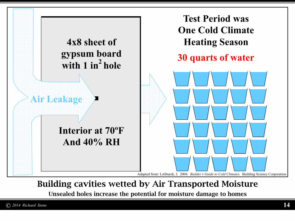
Building cavities wetted by Air Transported Moisture Unsealed holes increase the potential for moisture damage to homes
Adapted from: Lstiburek, J. 2004. Builder’s Guide to Cold Climates. Building Science Corporation
4x8 sheet of gypsum board with 1 in2 hole
Interior at 70ºF And 40% RH
Air Leakage
Test Period was One Cold Climate
Heating Season 30 quarts of water

© 2014 Richard Stone 15
New homes look good on the outside. . .
• Blower door depressurization to expose thermal bypasses and air-leakage pathways through the framing
• Thermal imaging using Infra-red to identify changes in surface temperature resulting from bypasses and air-leakage
. . . but all the details under the surface need to be done right
Design and execution of critical construction details can be tested using:
© 2014 Richard Stone 16
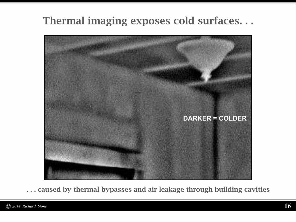
Thermal imaging exposes cold surfaces. . .
. . . caused by thermal bypasses and air leakage through building cavities
DARKER = COLDER
© 2014 Richard Stone 17
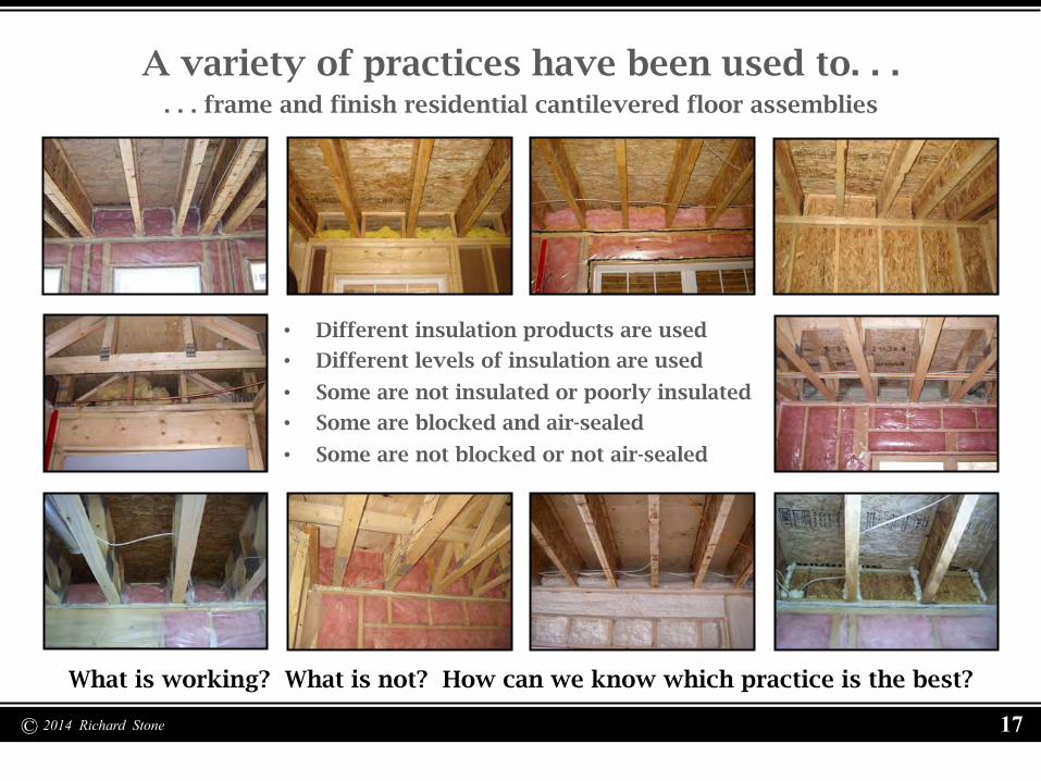
A variety of practices have been used to. . . . . . frame and finish residential cantilevered floor assemblies
• Different insulation products are used
• Different levels of insulation are used
• Some are not insulated or poorly insulated
• Some are blocked and air-sealed
• Some are not blocked or not air-sealed
What is working? What is not? How can we know which practice is the best?

© 2014 Richard Stone 18
We can compare them through testing!
Three representative methods of insulating cantilevered floors were selected:
• R-19 fiberglass batt with the cavity open to the inside
• R-30 fiberglass batt (completely filled), blocked, and air-sealed
• R-30 closed cell spray-applied plastic foam insulation

© 2014 Richard Stone 19
R-19 fiberglass batt
• Many older homes with insulated cantilevered floors used this method
• Wide variation in product and quality control is seen
Cavity open to the inside
Wagner, 1992

© 2014 Richard Stone 20
R-30 fiberglass batt
• Became common following the 80’s energy crisis and code updates
• Wide variety of blocking and sealing strategies is seen
Completely filled, blocked, and air-sealed
Legg, 1997

© 2014 Richard Stone 21
R-30 closed cell foam
• Most recently introduced method in residential buildings
• Closed cell foam acts as vapor retarder and air-barrier
Spray-applied plastic insulation
Lstiburek, 2004

© 2014 Richard Stone 22
Roseville, Minnesota home used as research site
1971 2x4 framed walls with trussed roof framing – no foundation insulation

© 2014 Richard Stone 23
24 inch Cantilever on North Elevation
Extended floor has 2x10 fir joists at16 inches on center

© 2014 Richard Stone 24
Cantilevered floor in “as found” condition Variety of fiberglass batts “stuffed” into cavities in varying configurations
Interior conditions maintained at 68-75 degrees F. and at approximately 35% R.H.
Natural gas forced air heating, central air conditioning, and dehumidification
Proposed layout for the west half with a guard cavity on each side of test cavities
Test cavity layout for the east half would be reversed in a “bookend” fashion

© 2014 Richard Stone 25
Temperature and moisture sensor locations

© 2014 Richard Stone 26
Sensor placement uniformity was maintained. . .
. . . by use of templates and a standard grid layout in all test cavities

© 2014 Richard Stone 27
A mock-up sensor group was assembled. . .
. . . to assure that mounting brackets and cables had necessary clearances
© 2014 Richard Stone 28
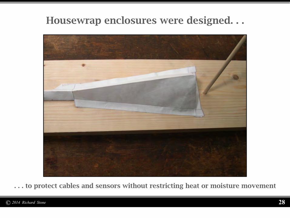
Housewrap enclosures were designed. . .
. . . to protect cables and sensors without restricting heat or moisture movement

© 2014 Richard Stone 29
Existing insulation was removed from the cantilever. . .
. . . and all dirt and debris was removed from all of the cavities

© 2014 Richard Stone 30
More dirt (evidence of infiltration) was found. . .
. . . on the fiberglass batts where air leakage paths were present

© 2014 Richard Stone 31
Temporary protection from the weather. . .
. . . was created by first installing foam weather-stripping

© 2014 Richard Stone 32
1 inch poly-isocyanurate insulation board blocking. . .
. . . was held against the weather-stripping in each cavity with spring wires

© 2014 Richard Stone 33
Old water stains were present in all cavities. . .
. . . but all components of the cantilevered floor were still sound

© 2014 Richard Stone 34
The fir plywood soffit panels were removed. . .
. . . and also showed evidence of water staining and infiltration

© 2014 Richard Stone 35
Fiber-board had been installed above the plywood . . .
. . . and when removed, showed evidence of water staining but not decay

© 2014 Richard Stone 36
The cantilever assembly was opened completely. . .
. . . for inspection, retrofit, and installation of research components

© 2014 Richard Stone 37
It was found that insulation had never been installed. . .
. . . in the corner cavities that extended beyond the foundation walls

© 2014 Richard Stone 38
The cantilevered floor and workspace was enclosed. . .
. . . so the research retrofit build-out could continue into the winter

© 2014 Richard Stone 39
Cantilever joists varied as much as 3/8 inch. . .
. . . so shims were created to even out cantilever dimensions at the bottom

© 2014 Richard Stone 40
Enclosures for exterior boundary condition sensors. . .
. . . were fabricated for installation below the outer edge of the cantilever

© 2014 Richard Stone 41
Installation of sensor enclosures was completed. . .
. . . and cables were routed and secured inside a guard cavity

© 2014 Richard Stone 42
The cable pathway was sealed. . .
. . . at the inside of the cavity and the outside of the PVC conduit

© 2014 Richard Stone 43
Shims and blocking were installed. . .
. . . to provide fastener support for the individual plywood soffit panels

© 2014 Richard Stone 44
Air-sealing of the cantilevered floor cavities. . .
. . . was completed with silicone sealant at seams and closed cell foam gaskets

© 2014 Richard Stone 45
20 Plywood soffit panels were cut to fit. . .
. . . and temporarily installed using spacers and fastened with screws

© 2014 Richard Stone 46
The unfinished soffit panels were removed. . .
. . . for the installation of six sensor panels and for painting

© 2014 Richard Stone 47
Clear vertical grain Douglas Fir sensor panels. . .
. . . were fabricated and inserted into the six test cavity plywood soffit panels

© 2014 Richard Stone 48
Sensor performance will be enhanced. . .
. . . by wood species uniformity and panel thickness and R-value

© 2014 Richard Stone 49
Sensor Group Layout and ID Example

© 2014 Richard Stone 50

© 2014 Richard Stone 51
Sensor groups installed in cavity locations. . .
. . . before testing and installation of sensor enclosures
© 2014 Richard Stone 52
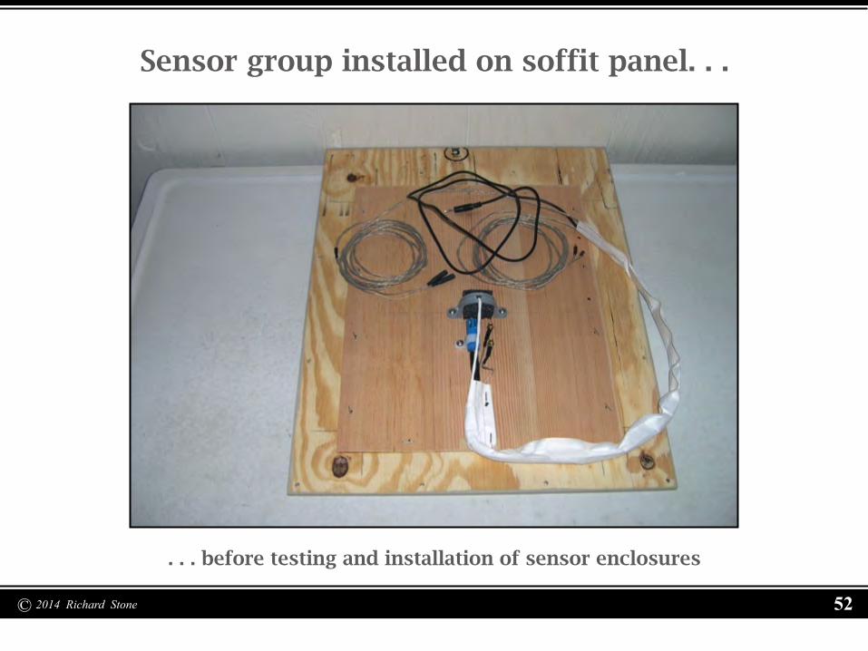
Sensor group installed on soffit panel. . .
. . . before testing and installation of sensor enclosures

© 2014 Richard Stone 53
Air temperature and relative humidity (RH). . .
. . . values from a digital hygrometer were recorded for comparison

© 2014 Richard Stone 54
RH and air temperature from the sensors. . .
. . . were recorded and compared to the recorded hygrometer values

© 2014 Richard Stone 55
Wood moisture content (MC). . .
. . . values were recorded at the pins in the sensor group
© 2014 Richard Stone 56
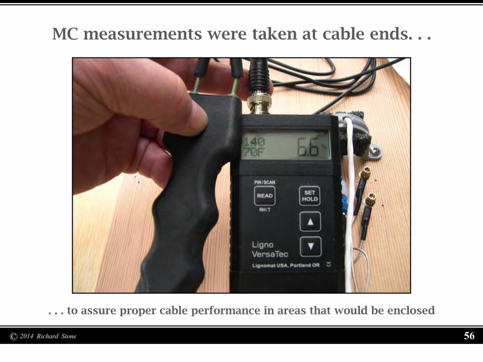
MC measurements were taken at cable ends. . .
. . . to assure proper cable performance in areas that would be enclosed

© 2014 Richard Stone 57
Temperature of the wood was measured. . .
. . . to compare with the value transmitted by the sensor in the wood

© 2014 Richard Stone 58
A record of values measured during installation. . .
. . . at every sensor in every location was compared to values recorded online

© 2014 Richard Stone 59
Sensor group enclosures were installed. . .
. . . after testing of all sensors during the installation process

© 2014 Richard Stone 60
Masking was installed to protect the interior side. . .
. . . of the cantilevered floor area during the sprayed foam application

© 2014 Richard Stone 61
Closed cell polyurethane foam installation. . .
. . . was completed in compliance with the manufacturer’s recommendations

© 2014 Richard Stone 62
After allowing time for the foam to cure. . .
. . . the masking in the cantilever area was removed

© 2014 Richard Stone 63
Additional masking had been applied. . .
. . . to sensor enclosures not imbedded in the closed cell foam insulation

© 2014 Richard Stone 64
Sensors open to the interior of the house. . .
. . . and their enclosures were protected during the spray foam application

© 2014 Richard Stone 65
R-19 fiberglass batts were installed. . .
. . . at the cavity bottom and against the double rim joist

© 2014 Richard Stone 66
R-30 fiberglass batts were filled completely. . .
. . . trimming around sensor group enclosures
© 2014 Richard Stone 67
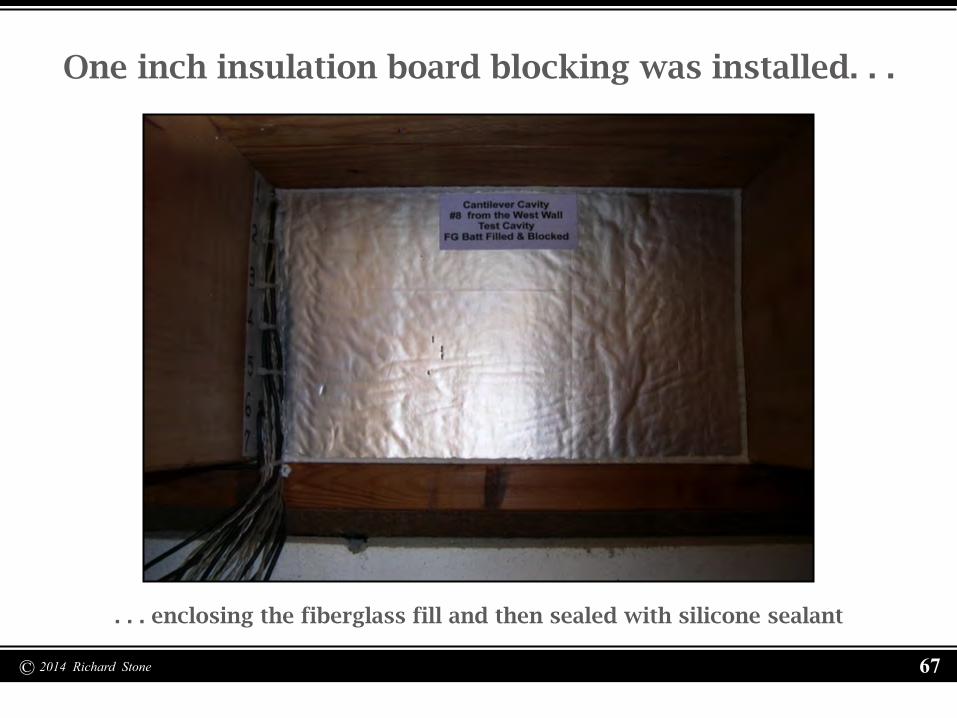
One inch insulation board blocking was installed. . .
. . . enclosing the fiberglass fill and then sealed with silicone sealant

© 2014 Richard Stone 68
Sensor cables were sorted and bundled. . .
. . . while still connected to the temporary transmitter arrays

© 2014 Richard Stone 69
Sensor cable sorting was completed. . .
. . . for both halves of the cantilever and routed to the final transmitter locations

© 2014 Richard Stone 70
Cavities and cables were labeled. . .
. . . to allow easy identification of all components of the research project

© 2014 Richard Stone 71
Cable bundles were anchored to the sill plate. . .
. . . and all extension cables and connections checked for continuity

© 2014 Richard Stone 72
Boundary condition and Internet cables. . .
. . . were also routed to the transmitter arrays and data logger location
© 2014 Richard Stone 73
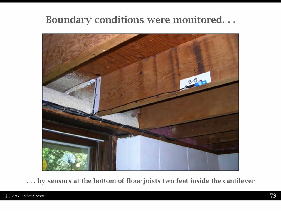
Boundary conditions were monitored. . .
. . . by sensors at the bottom of floor joists two feet inside the cantilever

© 2014 Richard Stone 74
Main floor boundary condition sensors. . .
. . . on either side of the interior wall above the center of the cantilever

© 2014 Richard Stone 75
A Housewrap enclosure was added. . .
. . . around the exterior boundary sensors inside of the plastic shields

© 2014 Richard Stone 76
The data logger and Internet connection. . .
. . . was located between the two transmitter arrays

© 2014 Richard Stone 77
The first air temperature/RH sensor failure. . .
. . . occurred above the soffit in a foam insulated cavity

© 2014 Richard Stone 78
The sensor was removed and replaced. . .
. . . after testing to confirm the issue and the soffit was then re-sealed

© 2014 Richard Stone 79
A section from the DATA SET

© 2014 Richard Stone 80
6.8°C - Location 8-2-Ti December 7, 2013 at 11:00
Floor temperature and thermal comfort

© 2014 Richard Stone 81
-22.7°C - Location B-4-Te December 7, 2013 at 6:00
Temperatures at boundary locations

© 2014 Richard Stone 82

© 2014 Richard Stone 83

© 2014 Richard Stone 84

© 2014 Richard Stone 85

© 2014 Richard Stone 86
•
25⁰ C
20⁰ C
15⁰ C
•
•
•
Actual Floor Temperature vs Optimal Floor Temperature
22⁰ C
Optimal temperature for oak flooring 26⁰C / 78.8⁰F
Optimal temperature for carpeted floor 24.5⁰C / 76.1⁰F based on 10 minute exposure of bare feet
based on 10 minute exposure of bare feet
Source: Olesen, B. (1977). Thermal comfort requirements for floors occupied by people with bare feet. ASHRAE Transactions. vol. 83 (2): page 52.
“At floor temperatures below 20-22⁰C [68-71.6⁰F] the percentage of people experiencing cold feet increases rapidly.”
Source: Olesen, B. (1975) Termiske komfortkrav til gulve (Thermal comfort requirements for floors) Translated and quoted in: Fanger, O. (1977). Local Discomfort to the human body caused by non-uniform thermal environments. The Annals of Occupational Hygiene, 20 (3): page 289.
Oak floor surface above test cavity 14 – 16.6⁰C / 61.9⁰F
Carpet surface above test cavity 5 – 16.5⁰C / 61.7⁰F
Carpet surface above test cavity 2 – 16.4⁰C / 61.5⁰F
Oak floor surface above test cavity 17 – 16.3⁰C / 61.3⁰F
Oak floor surface above test cavity 11 – 15.5⁰C / 59.9⁰F
Carpet surface above test cavity 8 – 15.3⁰C / 59.5⁰F
•
•
•
•
•
• • •
• • • •

© 2014 Richard Stone 87

© 2014 Richard Stone 88
Boundary location RH comparisons

© 2014 Richard Stone 89
Soffit location RH comparisons

© 2014 Richard Stone 90
Moisture behavior at soffit in R-30/sealed cavity

© 2014 Richard Stone 91
Moisture behavior at soffit in R-30/ foamed cavity

© 2014 Richard Stone 92
Moisture behavior at soffit in R-19/open cavity

© 2014 Richard Stone 93
Questions and Discussion

© 2014 Richard Stone 94
References Cited
Slide 6 - Gisling. (2007). File:The Fugong Temple Wooden Pagoda.jpg – Wikimedia Commons. Retrieved from http://commons.wikimedia.org/wiki/File: The_Fugong_Temple_Wooden_Pagoda.jpg Slide 6 - Dunn, A. (2004). File:DoubleJettiedBuilding.jpg – Wikimedia Commons. Retrieved from http://commons,wikimedia.org/File:DoubleJettiedBuilding.jpg Slide 12 - Lstiburek, J. (2004) Builder’s Guide to Cold Climates. Westford, MA. Building Science Press. Revised. Sixth Printing. October 2004. Page 121. Slide 13 - Lstiburek, J. (2004) Builder’s Guide to Cold Climates. Westford, MA. Building Science Press. Revised. Sixth Printing. October 2004. Page 121. Slide 18 - Wagner, W. (1992). Modern Carpentry. South Holland, IL. The Goodheart-Willcox Company, Inc. Page 343. Slide 19 - Legg, D. (1997). Air-sealing one-and-a-half story homes. In Steven Bliss (Ed.), Troubleshooting Guide to Residential Construction. (pp. 163-166). Williston, VT: The Journal of Light Construction. Page 165. Slide 20 - Lstiburek, J. (2004) Builder’s Guide to Cold Climates. Westford, MA. Building Science Press. Revised. Sixth Printing. October 2004. Page 278. Slide 85 - Fanger, P. (1977). Local discomfort to the human body caused by non-uniform thermal environments. The Annals of Occupational Hygiene, 20(3): 285-291. Slide 85 - Olesen, B. (1977). Thermal comfort requirements for floors occupied by people with bare feet. ASHRAE Transactions. vol. 83 (2): 41-57.
All graphics, photos, tables, text, and graphs not credited above were produced by Richard Stone in partial fulfillment of the requirements for the Degree of Master of Science awarded by the University of Minnesota in May 2014

© 2014 Richard Stone 95