saw mill owner's manual - northern tool · when saw mill is not in use, ... death. the...
TRANSCRIPT

Saw Mill
OWNER’S MANUAL
WARNING:
Read carefully and understand all ASSEMBLY AND OPERATION INSTRUCTIONS before operating. Failure to follow the safety rules and other basic safety precautions may result in serious personal injury.
01062015
Item# TMW-2020SMBS

Thank you very much for choosing this product! For future reference, please complete the owner’s record below: Model: TMW-2020SMBS Purchase Date: _______________ Save the receipt, warranty and these instructions. It is important that you read the entire manual to become familiar with this product before you begin using it. This product is designed for certain applications only. The manufacturer cannot be responsible for issues arising from modification. We strongly recommend this product not be modified and/or used for any application other than that for which it was designed. If you have any questions relative to a particular application, DO NOT use the product until you have first contacted us to determine if it can or should be performed on the product. For technical questions please call 1-218-943-6290.
INTENDED USE The Timber Tuff Saw Mill is portable and versatile which makes it a great tool for any lumber project. It has the
capabilities of sawing logs up to 20” in diameter, 4 ½” thick and a cutting length of 110”. It is equipped with a 306cc Briggs & Stratton Engine and a U.S. Lenox Blade with a blade speed of 3150 fpm.
TECHNICAL SPECIFICATIONS
Item Description
Capacity 20” diameter, 4-1/2” thick, 110” in length
Engine Briggs & Stratton 306cc
Blade U.S. Lennox 144 x 1-1/4 x 0.035
Dimensions 153.55” x70.87” x 66.15”
GENERAL SAFETY RULES
WARNING: Read and understand all instructions. Failure to follow all instructions listed below may
result in serious injury.
CAUTION: Do not allow persons to operate or assemble this saw mil until they have read this manual and have developed a thorough understanding of how the saw mill works.
WARNING: The warnings, cautions, and instructions discussed in this instruction manual cannot cover all possible conditions or situations that could occur. It must be understood by the operator that common sense and caution are factors which cannot be built into this product, but must be supplied by the operator.

SAVE THESE INSTRUCTIONS
WORK AREA • Keep work area clean, free of clutter and well lit. Cluttered and dark work areas can cause accidents.
• Keep children and bystanders away while operating the sawn mill. Distractions can cause you to lose control, so visitors should remain at a safe distance from the work area.
• Be alert of your surroundings. Using a saw mill in confined work areas may put you dangerously close to cutting tools and rotating parts.
PERSONAL SAFETY • Stay alert, watch what you are doing and use common sense when using a saw mill. Do not use a saw mill
while you are tired or under the influence of drugs, alcohol or medication. A moment of inattention while operating a saw mill may result in serious personal injury.
• Dress properly. Do not wear loose clothing, dangling objects, or jewelry. Keep your hair, clothing and gloves away from moving parts. Loose clothes, jewelry or long hair can be caught in moving parts.
• Use safety apparel and equipment. Use safety goggles or safety glasses with side shields which comply with current national standards, or when needed, a face shield. Use a dust mask if working in dusty work conditions. This applies to all persons in the work area. Also use non-skid safety shoes, hardhat, gloves, dust collection systems, and hearing protection when appropriate.
SAW MILL USE AND CARE • Do not modify the saw mill in any way. Unauthorized modification may impair the function and/or safety
and could affect the life of the equipment. There are specific applications for which the saw mill was designed.
• Always check for damaged or worn out parts before using the saw mill. Broken parts will affect the saw mill operation. Replace or repair damaged or worn parts immediately.
• Do not exceed the saw mill load capacity.
• Distribute the load evenly. Uneven loads may cause the saw mill to tip, resulting in personal injury to the operator or others. Log should be secured before sawing.
• Use the saw mill on flat and level surfaces capable of supporting the saw mill and its maximum load. Pulling or pushing a load on a slanted or uneven surface can result in loss of control. Saw mill needs to be on a flat and level surface before sawing.
• Store idle saw mill. When saw mill is not in use, store it in a secure place out of the reach of children. Inspect it for good working condition prior to storage and before re-use.

IMPORTANT SAFETY INFORMATION
WARNING! Read all instructions.
Failure to follow all instructions listed below may result in fire, serious injury and/or
DEATH. The warnings and precautions discussed in this manual cannot cover all possible
conditions and situations that may occur. It must be understood by the operator that common
sense and caution are factors which cannot be built into this product, but must be supplied by the
operator.
SAVE THESE INSTRUCTIONS Set Up Precautions
1. Gasoline fuel and fumes are flammable, and potentially explosive. Use proper fuel storage and handling
procedures. Do not store fuel or other flammable materials near the machine.
2. Have fire extinguishers nearby.
3. Operation of this equipment may create sparks that can start fires around brush and dry vegetation. A
spark arrestor may be required. The operator should contact local fire agencies for laws or regulations
relating to fire prevention requirements.
4. Set up and use only on a flat and level surface. Area must be well ventilated.
5. Wear ANSI-approved safety goggles, heavy-duty work gloves, and dust mask/respirator during set up.
6. Use only lubricants and fuel recommended in the engine manual or in the Specifications chart of this
manual.
Engine Precautions Follow engine precautions and instructions in the included engine instruction manual.
Operating Precautions CARBON MONOXIDE HAZARD Using an engine indoors CAN KILL YOU IN MINUTES. Engine exhaust contains carbon monoxide. This is a poison you cannot see or smell. NEVER use indoors EVEN IF doors and window are open.
Only use OUTSIDE and far away from windows, doors and vents.
1. Keep children and bystanders away from the equipment, especially during operation.
2. Do not leave the equipment unattended when it is running. Turn off the equipment (and remove safety keys, if available) before leaving the work area.
3. Wear ANSI-approved safety glasses, hearing protection, and NIOSH-approved dust mask/respirator under a
full face shield during use. Wearing steel toe shoes is also recommended.
4. Wear heavy-duty work gloves when handling the blades.

5. People with pacemakers should consult their physician before use. Electromagnetic fields in close proximity to a heart pacemaker could cause pacemaker interference or pacemaker failure. Caution is necessary when near the engine’s magneto or recoil starter.
6. Use only accessories that are recommended by Timber Tuff for your model. Accessories that may be suitable for one piece of equipment may become hazardous when used on another piece of equipment.
7. Do not operate in explosive atmospheres, such as in the presence of flammable liquids, gases, or dust. Gasoline-powered engines may ignite the dust or fumes.
8. Stay alert, watch what you are doing and use common sense when operating this piece of equipment. Do not use this piece of equipment while tired or under the influence of drugs, alcohol or medication.
9. Do not overreach. Keep proper footing and balance at all times. This enables better control of the equipment in unexpected situations.
10. Dress properly. Do not wear loose clothing or jewelry. Keep hair, clothing and gloves away from moving parts. Loose clothes, jewelry or long hair can be caught in moving parts.
11. Parts, especially exhaust system components, get very hot during use. Stay clear of hot parts.
12. Do not cover the engine or equipment during operation.
13. Keep the equipment, engine, and work area clean at all times.
11. Use the equipment, accessories, etc., in accordance with these instructions and in the manner intended for the particular type of equipment, taking into account the working conditions and the work to be performed. Use of the equipment for operations different from those intended could result in a hazardous situation.
12. Do not operate the equipment with known leaks in the engine's fuel system.
13. WARNING: The brass components of this product contain lead, a chemical known to the State of California to cause birth defects (or other reproductive harm). (California Health & Safety code § 25249.5, et seq.)
14. WARNING: Some dust created by power sanding, sawing, grinding, drilling, and other construction activities, contains chemicals known [to the State of California] to cause cancer, birth defects or other reproductive harm. Some examples of these chemicals are:
Lead from lead-based paints Crystalline silica from bricks and cement or other masonry products Arsenic and chromium from chemically treated lumber Your risk from these exposures varies, depending on how often you do this type of work. To reduce your exposure to these chemicals: work in a well ventilated area, and work with approved safety equipment, such as those dust masks that are specially designed to filter out microscopic particles. (California Health & Safety Code § 25249.5, et seq.)
15. This product contains or, when used, produces a chemical known to the State of California to cause cancer and birth defects or other reproductive harm. (California Health & Safety Code § 25249.5, et seq.)
16. When spills of fuel or oil occur, they must be cleaned up immediately. Dispose of fluids and cleaning materials as per any local, state or federal codes and regulations. Store oil rags in a bottom-ventilated, covered, metal container.
17. Keep hands and feet away from moving parts. Do not reach over or across equipment while operating.
18. Before use, check for misalignment or binding of moving parts, breakage of parts, and any other condition that my affect the equipment’s operation. If damaged, have the equipment serviced before using. Many accidents are caused by poorly maintained equipment.
19. Use the correct equipment for the application. Do not modify the equipment and do not use the equipment for a purpose for which it is not intended.

20. Keep hands and feet away from moving parts. Do not reach over or across equipment while operating.
21. Before use, check for misalignment or binding of any moving parts, breakage of parts, and any other condition that may affect the equipment’s operation. If damaged, have the equipment serviced before using. Many accidents are caused by poorly managed equipment.
22. Use the correct equipment for the application. Do not modify the equipment and do not use the equipment for a purpose for which it is not intended.
Service Precautions
1. Before service, maintenance or cleaning: a. Turn the engine switch to its “OFF” position. b. Allow the engine to completely cool c. Then remove the spark plug wire(s) from the spark plug(s).
2. Keep all safety guards in place and in proper working order. Safety guards include muffler, air cleaner, mechanical guards and heat shields, among other guards.
3. Do not alter or adjust any part of the equipment or its engine that is sealed by the manufacturer or distributor. Only a qualified service technician may adjust parts that may increase or decrease governed engine speed.
4. Wear ANSI-approved safety goggles, heavy-duty work gloves, and dust mask/respirator during service. 5. Maintain labels on the equipment. These carry important information. If unreadable or missing, contact
Timber Tuff for a replacement. 6. Have the equipment serviced by a qualified repair person using only identical replacement parts. This will
ensure that the safety of the equipment is maintained. Do not attempt any service or maintenance procedures not explained in this manual or any procedures that you are uncertain about your ability to perform safely or correctly.
7. Store equipment out of the reach of children. 8. Follow scheduled engine and equipment maintenance. 9. Refueling:
a. Do not smoke, or allow sparks, flames, or other sources of ignition around the equipment, especially when refueling.
b. Do not refill the fuel tank while the engine is running or hot. c. Do not fill fuel tank to the top. Leave a little room for the fuel to expand as needed. d. Refuel in a well-ventilated area only.
Specifications
Fuel Type 87+ octane unleaded gasoline
Fuel Capacity 1 Gallon
Coolant Tank Capacity 4.2 Quarts
Blade Speed 3,279 FPM
Log Diameter 20” Maximum
Board Width 20” Maximum
Cutting Thickness 4-1/2” Maximum
Cutting Length 9’-2” Maximum (110”)
Note: Engine specifications are found in the engine manual supplied with this equipment.
TO PREVENT SERIOUS INJURY: Operate only with proper spark arrestor installed. Operation of this equipment may create sparks that can start fires around dry vegetation and brush. A spark arrestor may be required. The operator should contact local fire agencies for laws or regulations relating to fire prevention requirements.
TO PREVENT SERIOUS INJURY: The Saw Mill is dangerous if assembled incorrectly. If you do not feel completely comfortable assembling it, then have a qualified technician assemble it.

Assembly
Read all of the safety precautions and warnings in this manual before setting up or using this product.
TO PREVENT SERIOUS INJURY: Operate only with proper spark arrestor installed. Operation of this equipment may create sparks that can start fires around dry vegetation and brush. A spark arrestor may be required. The operator should contact local fire agencies for laws or regulations relating to fire prevention requirements.
TO PREVENT SERIOUS INJURY: The Saw Mill is dangerous if assembled incorrectly. If you do not feel completely comfortable assembling it, then have a qualified technician assemble it. Note: For additional information regarding the parts listed, refer to Assembly Diagram near the end of this manual.
1. Secure Wheels (1) onto Right Wheel Frame (7a) with two Bolts M20x100 (6) and Nuts M20 (2). Attach Right Wheel Frame, Round Post (20) and the Round Clamp (10) with two Bolts M12x80 (8) and Nuts M12 (9). As shown in Figure A. Note: Do not tighten Bolts (8) and Nuts (9) yet.
10
7a
20
8, 9
6,2
2 2 1
Figure A: Right Wheel Frame

2. Secure Wheels (1) onto Left Wheel Frame (3a) with two Bolts M20x100 (6) and Nuts M20 (2). Then attach Left Wheel Frame, Square Post (48) and Square Clamp (4) with two Bolts (58) and Hex Nuts (5) as shown in Figure B. Note: Do not tighten Bolts (58) and Nuts (5) yet.
3. Slide the Round Post (20) into the Blade Guard (50), as shown In Figure C. Adjust the bolts (18) until Blade Guard can move smoothly on the round post. Then secure it in place with the Right Lock Handle (59).
48
4 58, 5
3a
6, 2
Figure B: Left Wheel Frame
Round Post (20)
Blade Guard (50)
Right Lock Handle (59)
Figure C: Right Lock Handle
Bolts (18)

4. Slide the Square Post (48) into the Blade Guard (50), as shown in Figure D. Adjust the bolts until it can move smoothly on the square post. Then secure it in place with the Left Lock Handle (54).
5. Lay out the Track sections (78, 92) as shown in Figure E.
6. Use the Bolts (22) and Nuts (25) to fasten the End Stops (79) to the Track Sections, as shown in Figure E.
7. Use the Flange Bolts (77) and Flange Nuts (84) to fasten the Center Support (90a) and Middle Supports (81a) to the Track Sections (78, 92), as shown in Figure E.
NOTE: The Track (78) and Track (92) must be aligned not only on the top surface, but also on the side surface. The gap between these two parts must be small. If the top surface of the Tracks are not aligned, use a grinder or file (not included) to smooth them out.
Left Lock
Handle (54)
Square
Post
(48)
Blade
Guard (50)
Figure D: Left Lock Handle
80a - End
Support
78
81a –
Middle
Support
92
82
79
22
92 91
78
77
25 Saw mill
finishes
cut at this
end
Saw mill
starts cut
from this
end
NOTE: After assembly, the center to
center distance of the Track must be
30-5/16”+/-1/16”
89 – Log
Clamp
Assy
89 – Log
Clamp
Assy
80a – End
Support
80a – Center
Support
80a – Middle
Support
Figure E: Track Assembly
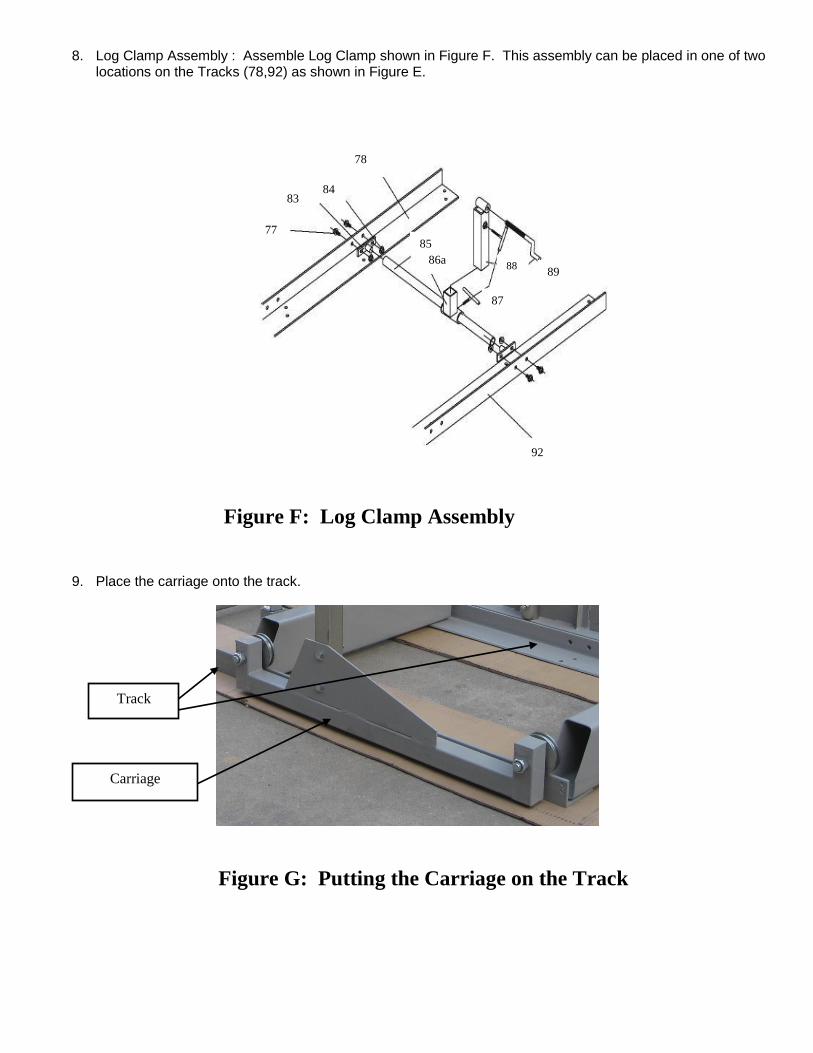
8. Log Clamp Assembly : Assemble Log Clamp shown in Figure F. This assembly can be placed in one of two locations on the Tracks (78,92) as shown in Figure E.
9. Place the carriage onto the track.
85 86a
87
88
89
92
77
83 84
78
Figure F: Log Clamp Assembly
Track
Carriage
Figure G: Putting the Carriage on the Track

10. Place the Top Frame (23) on the Posts (20, 48) as shown in Figure H.
11. Secure the two Bolts (22) with Nut (25) attaching the Top Frame (23) to the Round Post (20) as shown in Figure I.
12. Attach the Top Frame (23) to the Square Post (48) using the Bolts (49) and Top Frame Brace (101) as shown in Figure J.
Figure H: Top Frame
Figure I: Top Frame Round Post Bolts
Figure J: Top Frame Square Post Bolts 2
23
48 20
Bolts (22) and Nuts (25)
Top Frame (23)
Round Post (20)
Top Frame (23)
Square Post (48) Top Frame Brace
(101)
Bolts (49)

13. NOTE: Tighten the Bolts (8, 58) and Nuts (5,9) – refer back to Figure A & B.
14. Attached the External tube (34) and the Water Tank Tray (45) to the Top Frame (23) using the Bolts (44),
Spring Washer (98), and Nut (99), as shown In Figure K.
15. Thread the Cable Anchor Bolts (46) into the Blade Guard (50) as shown in Figure L.
34 44
23
45
99
98
Figure K: Water Tank Tray and External Tube Assembly
Figure L: Cable Anchor Bolt Locations
46

16. Route Cables as shown in Figure M. Hook the loops around the two posts on the back of the External Tube (34).
17. Loosen the Bolt (16) and Nut (32). Rotate the Tension handle (14) in a clockwise direction to properly tension the Blade, as shown in Figure N.
NOTE: Pull up and down on Blade at Center Guard. Allow for no more that ¼” – ½” movement up or down (“give”) on the Blade. The ¼” – ½” give indicates proper Blade tension.
Figure M: Cable Route
Figure N: Tension Handle
14
32 16
34

18. Slide Fixed Block (71) until it gently touches the Blade. Then tighten the Bolt (70), fastening it in place. See
Figure O. Repeat for the remaining Fixed Blocks until there is 0.02” – 0.04” clearance between Fixed Blocks and Blade.
19. Rotate the Band Wheel (66) slowly counterclockwise, watching relative position of the Blade (69) and the
Band Wheels (66).
20. If the Blade stays centered on the wheels, tighten the lock nuts shown in Figure P. If the Blade does not stay centered, adjust the bolts shown on Figure P slightly and then rotate the band wheel again. See instructions that follow.
NOTE: Adjust Blade again after replacement. Refer to Figure P for the following instructions: BEFORE any adjustment, loosen Bolts 51E and 51F and Nuts 52C and 52D. If after replacement Blade starts to shift back towards operator, loosen Nut 52A and hold Bolt 53G with a wrench. Then tighten Nut 52A after adjustment. Continue making small adjustments until Blade stays centered. AFTER any adjustment, tighten Bolts 51E and 51F and nuts 52C and 52D.
Figure O: Fixed Block and Manual Rotation
Fixed Block (71)
Bolt (70)
52D 51F
52A 53G
G
51E
52C
52B
Figure P: Adjustment Bolts
Band Wheel (66)

21. Install Throttle control (93) on Push Handle (94) as shown in Figure Q.
22. Lubricate the Round Post (20) and the Square post (48) with lithium grease to allow the Saw Head to move smoothly.
23. Install the Water Tank (95) into the Water Tank Tray (45).
24. Route the Water Tube (97) through the bracket on the lower right of the Blade Guard (50). Secure in place with the tip facing the blade using the water tube holding bolt shown in Figure R, but do not overtighten.
Figure Q: Throttle Control
Water Tube
(97)
Water Tube Holding Bolt
Figure R: Water Tube
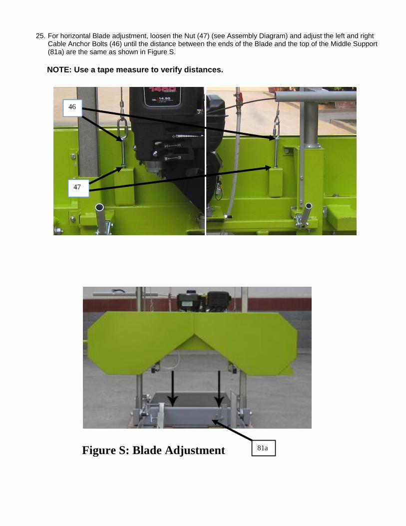
25. For horizontal Blade adjustment, loosen the Nut (47) (see Assembly Diagram) and adjust the left and right
Cable Anchor Bolts (46) until the distance between the ends of the Blade and the top of the Middle Support (81a) are the same as shown in Figure S.
NOTE: Use a tape measure to verify distances.
Figure S: Blade Adjustment
46
47
81a

OPERATING INSTRUCTIONS Read all of the safety precautions and warnings in this manual before setting up or using this product.
Engine Operation
Inspect engine and equipment looking for damaged, loose or missing parts before operating. If any problems are found, do not use equipment until fixed properly.
Start Procedure Before starting the engine:
a. Follow the Set Up Instructions to prepare the equipment. Follow all instructions in The separate engine manual provided with the engine.
b. Inspect the equipment and engine.
c. Fill the engine with the proper amount and type of fuel and oil.
d. Read the Equipment Operation section that follows.
1. Start and operate the engine according to the provided engine manual. 2. Replacement engine operating instructions can be obtained from the engine manufacturer.

Equipment Operation
1. Wear heavy-duty work gloves, ANSI-approved goggles behind a full face shield, steel-toed work boots, and a dust mask.
2. Operate only with the assistance of another qualified person. 3. Fill the Water Tank with clean water. 4. The maximum log diameter that can be cut is 20”. The maximum board width that can be cut is 20”
The log must be at least 3’ 8” long and must rest on at least two Supports (81a, 90a) to prevent instability.
5. Cut branches off the log to be processed before sawing. 6. Do not cut logs containing foreign objects (nails, metal, etc.). This will cause Blade damage and could cause
serious injury. 7. Choose the Short Log Supports (91) or the Long Log Supports (82) according to the log diameter. 8. Place the log to be cut on the Supports. See Figure T. Brace the log against the Log Supports (82 or 91) to
prevent movement during sawing. The log should be positioned so that the force of cutting holds it against the supports. Log supports (82 or 91) need to be lower than the thickness of the board being cut to avoid blade damage.
9. Clamp the log in place against the Log Supports (82 or 91) using the Log Clamp Assembly (89) in the location shown in Figure T.
10. Tighten all Bolts and T-Handles on the Log Clamp Assembly (89) and the Log Supports (82 or 91). Verify that they are securely in place before proceeding. NOTE: Make sure the Log Clamp Assembly (89) does NOT interfere with the Saw Blade when sawing. The Log Clamp Assembly (89) should be lower than the Saw Blade at all times.
Clamp Log
Here (89) Log on
Supports
(91 or 82)
Figure T: Lumber Position
Scale Pointer
Scale
Pointer
Knob Scale
Height Adjustment
Handle
Figure U: Scale and Scale Pointer
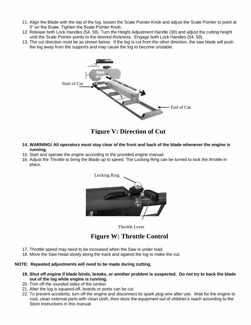
11. Align the Blade with the top of the log, loosen the Scale Pointer Knob and adjust the Scale Pointer to point at
0” on the Scale. Tighten the Scale Pointer Knob. 12. Release both Lock Handles (54, 59). Turn the Height Adjustment Handle (30) and adjust the cutting height
until the Scale Pointer points to the desired thickness. Engage both Lock Handles (54, 59). 13. The cut direction must be as shown below. If the log is cut from the other direction, the saw blade will push
the log away from the supports and may cause the log to become unstable.
14. WARNING! All operators must stay clear of the front and back of the blade whenever the engine is running.
15. Start and operate the engine according to the provided engine manual. 16. Adjust the Throttle to bring the Blade up to speed. The Locking Ring can be turned to lock the throttle in
place.
17. Throttle speed may need to be increased when the Saw is under load. 18. Move the Saw Head slowly along the track and against the log to make the cut.
NOTE: Repeated adjustments will need to be made during cutting.
19. Shut off engine if blade binds, breaks, or another problem is suspected. Do not try to back the blade out of the log while engine is running.
20. Trim off the rounded sides of the lumber 21. After the log is squared-off, boards or posts can be cut. 22. To prevent accidents, turn off the engine and disconnect its spark plug wire after use. Wait for the engine to
cool, clean external parts with clean cloth, then store the equipment out of children’s reach according to the Store instructions in this manual.
Figure V: Direction of Cut
Locking Ring
Throttle Lever
Figure W: Throttle Control
End of Cut
Start of Cut

Servicing
TO PREVENT SERIOUS INJURY FROM ACCIDENTAL STARTING: Turn the power Switch of the equipment to its “OFF” position, wait for the engine to cool, and disconnect the spark plug wire(s) before performing any inspection, maintenance or cleaning procedures. TO PREVENT SERIOUS INJURY FROM EQUIPMENT FAILURE: Do not use damaged equipment. If abnormal noise, vibration or excess smoking occurs, have the problem corrected before further use.
Maintenance Procedures Many maintenance procedures, including those not detailed in this manual, will need to be performed by a qualified technician for safety. If you have any doubts about your ability to safely service the equipment or engine, have a qualified technician service the equipment. NOTE: These procedures are in addition to the regular checks and maintenance explained as part of the regular operation of the engine and equipment.
Engine Maintenance and Service Follow the instruction found in the included engine manual.
Equipment Lubrication 1. Lubricate the Band Wheel Axles and Square and Round Posts with machine oil before each use. 2. Lubricate the Tension Handle with grease monthly or as needed.
Storage 1. Wait for engine to cool, then clean equipment with clean cloth. 2. Clean the engine and/or prepare it for storage according to engine manual instructions. 3. Apply a thin coat of rust preventive oil to all uncoated metal parts. 4. Cover and store in dry, well-ventilated area out of reach of children. 5. For cold weather operation, store the equipment in a cool dry area to prevent condensation and premature
wear.

Equipment Troubleshooting
Problem Possible Causes Probable Solutions Excessive blade
breakage.
1. Insufficient blade tension.
2. Incorrect speed or feed rate.
3. Log loose.
4. Blade rubs against wheel flange.
5. Blade teeth too coarse for
log, or blade too thick.
6. Teeth contacting lumber
before blade up to full speed.
7. Misaligned guides.
1. Increase blade tension.
2. Adjust speed or feed rate for the lumber being cut.
3. Make sure log is securely positioned
against supports. Remove stray branches
that prevent proper positioning.
4. Adjust blade tracking.
5. Use recommended blade only.
6. Allow blade to reach operating speed before cutting.
7. Align guides.
Premature
blade
dulling.
1. Teeth too coarse.
2. Blade rotating too quickly.
3. Hard spots or scale in/on material.
4. Blade installed backwards.
5. Insufficient blade tension.
6. Metal or other objects in the logs.
1. Use recommended blade only.
2. Use lower speed.
3. Reduce speed, increase feed pressure.
4. Properly install blade.
5. Tension blade properly.
Blade cuts crooked. 1. Log not square.
2. Feed pressure/rate too great.
3. Inadequate blade tension.
4. Dull blade.
5. Blade guide loose.
6. Insufficient blade tension.
1. Adjust log so that it is square with the blade.
2. Reduce feed rate.
3. Increase blade tension slightly.
4. Replace blade.
5. Adjust and secure blade guide.
Blade cuts rough. 1. Too much blade speed
and/ or rate of feed.
2. Blade is too coarse.
1. Reduce blade speed and feed rate.
2. Use recommended blade only.
Blade is twisting. 1. Cut is binding blade.
2. Blade tension too high.
1. Decrease feed pressure.
2. Decrease blade tension.
Unusual wear
on back or side
of blade.
1. Blade guides worn.
2. Blade guide bearing bracket is loose.
1. Replace blade guides.
2. Tighten blade guide bearing bracket.
Teeth ripping
from blade.
1. Teeth too coarse.
2. Feed rate incorrect.
3. Log loose.
4. Teeth filled with debris.
1. Use recommended blade only.
2. Adjust feed rate.
3. Make sure log is securely positioned
against supports. Remove stray branches
that prevent proper positioning.
4. Clean debris off blade.
Follow all safety precautions whenever diagnosing or servicing the equipment or engine

Parts List
Description Qty Part Description Qty
1 Wheel 4 52 Nut M12 4
2 Nut M20 4 53 Bolt M12 x 100 1
3a Left Wheel Frame 1 54 Left Lock Handle 1
4 Clamp 1 1 55 Bolt M8 x 45 6
5 Nut M12 6 56 Support tube 1
6 Bolt M20 x 100 4 57 Beam 1
7a Right Wheel Frame 1 58 Bolt M12 x 80 2
8 Bolt M12 x 80 5 59 Right Lock Handle 1
9 Nut M12 6 60 Bolt M10 x 25 2
10 Clamp 2 1 61 Elastic Washer 10 2
11 Bolt M8 x 20 9 62 Flat Washer 10 2
12 Bolt M10 x 25 21 63 Snap Ring 62 2
13 Bolt M12 x 65 3 64 Bearing 6305 RZ 4
14 Tension Handle 1 65 V-Belt B1900 1
15 Flat Washer 12 2 66 Band Wheel 2
16 Bolt M12 x 145 1 67 Clutch 1
17 Hanging Plate 1 68 Pin 1
18 Bolt M8 x 16 5 69 Blade 1
19 Right Clamp 1 70 Bolt M8 x 45 4
20 Round Post 1 71 Fixed Block 4
21 Lumber Thickness Scale 1 72 Blade Guide 2
22 Bolt M8 x 25 12 73 Blade Guide Shaft 2
23 Top Frame 1 74 Short Band Wheel Axle 1
24 Flat Washer 8 9 75 Long Band Wheel Axle 1
25 Nut M8 36 76 V-Belt B1422 1
26 Taper Pin B6 x 40 2 77 Flange Bolt M10 x 25 28
27 Elastic Pin B6 x 40 1 78 Track 1 2
28 Round Nut M14 x 1.5 2 79 End Stop 4
29 Height Adjustment Arm 1 80a End Support 2
30 Height Adjustment Handle 1 81a Middle Support 2
31 Bolt M12 x 65 6 82 Log Support 2
32 Nut M12 6 83 Rod Support 2
33 Guide Screw Base 1 84 Flange Nut M10 32
34 External Tube 1 85 Round Tube 1
35 Pulley 5 86a Rocker Tube Sleeve 1
36 Bolt M12 x 20 3 87 Log Support T-Handle M10x1.5x30 5
37 Snap Ring12 3 88 Rocker Tube 1
38 Washer 3 89 Log Clamp 1
39 Internal Tube 1 90a Center Support 1
40 Bolt M12 x 70 1 91 Short Log Support 2
41 Washer 1 92 Track 2 2
42 Flat Washer 2 93 Throttle Control 1
43 Nut M12 1 94 Push Handle 1
44 Bolt M10 x 45 2 95 Water Tank 1
45 Water Tank Tray 1 96 Shut Off Valve 1
46 Cable Anchor Bolt 2 97 Water Tube 1
47 Nut M10 4 98 Spring Washer 10 2
48 Square Post 1 99 Nut M10 4
49 Bolt M12 x 65 2 100 Blade Roller Bearing 2
50 Blade Guard 1 101 Top Frame Brace 1
51 Bolt M12 x 45 1

Assembly Diagram 1
101

Assembly Diagram 2
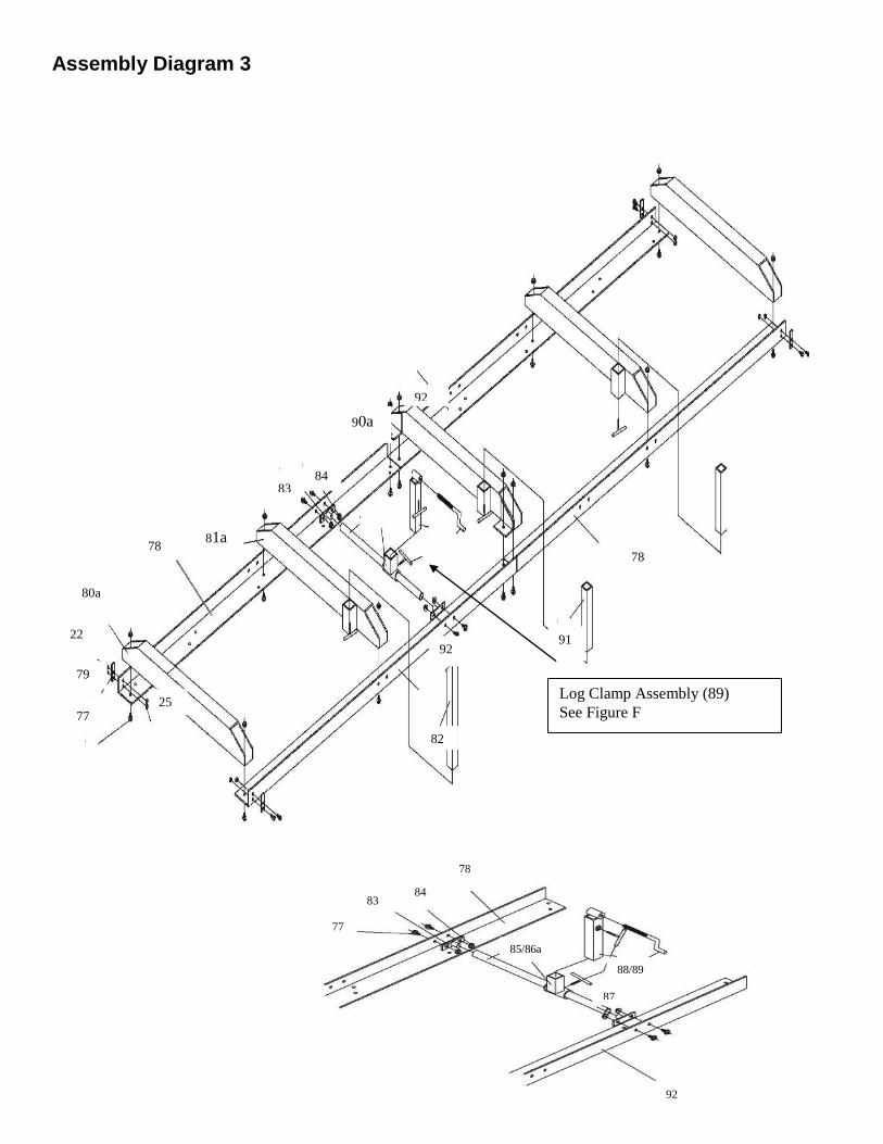
Assembly Diagram 3
92
90a
84 83
81a 78
80a
22
79
77 25
92
82
78
91
Log Clamp Assembly (89)
See Figure F
85/86a
78
87
88/89
92
84 83
77

PLEASE READ THE FOLLOWING CAREFULLY
The Manufacturer and/or Distributor has provided the parts list and assembly diagram in this manual
as a reference tool only. Neither the Manufacturer or Distributor makes any representation or
warranty of any kind to the buyer that he or she is qualified to make any repairs to the product, or that
he or she is qualified to replace any parts of the product. In fact, the Manufacturer and/or Distributor
expressly states that all repairs and parts replacements should be undertaken by certified and
licensed technicians, and not by the buyer. The buyer assumes all risk and liability arising out of his
or her repairs to the original product or replacement parts thereto, or arising out of his or her
installation of replacement parts thereto.
Note: Some parts are listed and shown for illustration purposed only, and are not available
individually as replacement parts.
WARRANTY One-year limited warranty For technical questions, please call 218-943-6290.
BAC Industries PO BOX 155
Miltona, MN 56354 Made in China