saving energy: using fine bubble...
TRANSCRIPT

Feature24Filtration+Separation January/February 2009
The need for technology
Fine bubble diffusers are all about satisfying the needs of the wastewater and sewage treatment industry, in order to achieve an efficient mass transfer of oxygen to the water, particularly that with a suspension of active sludge in a biological reactor. The oxygen allows bacteria in a fermentation process to digest the food source (the sewage). These processes break down the waste and reduce it, so that it can settle in clarifiers or get filtered by membranes in a last stage of treatment, before being returned as final effluent into the environment.
Originally the method was mechanical and worked well for decades. Atmospheric air or even pure oxygen was injected or mixed
with the liquor in the reactor, followed by mechanical stirring. More recently, the air diffusing concept developed, enabling us to distinguish between coarse bubbling systems (with a bubble size of 5-10mm diameter) and fine bubble diffusing (FBD) systems. The industry evolved to reach the point where we can now speak about ultra fine bubbles.
OPEX and CAPEX aspects
1. The main way of evaluating the operational expenses (OPEX) of the technology is by using the aeration efficiency (AE). This figure is a ratio between how many kilos of O2 can be transferred into wastewater by using 1 kWh of electrical energy, at the required desired dissolved oxygen levels
(usually 2mg/l). This criterion is easy to understand on one hand, but also subject to many other factors. We will return to these aspects elsewhere in this article.
2. The other aspect to consider is maintenance costs. It looks easy to clean a diffuser membrane as long it operates in an accessible medium, but is very difficult performing such operations in reactors with hundreds of thousands of cubic meters of sewage, without interrupting the process, and without causing higher related additional costs. Never argue the importance of minimal capital expenses (CAPEX) during initial plant design, or during refurbishment, as costs incurred later could make this a false economy.
Saving energy:
Using fine bubble diffusers F
ine bubble diffusers have largely replaced coarse bubble diffusers and mechanical aerators when it comes to treating sewage and wastewater. But what role does energy efficiency play? Adrian Ovezea explains how efficient use of this technology can save energy in treatment plants and looks at the different options available.
Figure 1: Blower station and aerial view of covered aeration reactors at WwTP Linz Austria. This plant uses biogas digestion and compensates power balance with the national grid. It uses the latest FBD technology from Aquaconsult Anlagenbau GmbH, Austria
Feature 25Filtration+Separation January/February 2009
TCO and WLC aspects
Total cost of ownership (TCO) and whole life costs (WLC) are the concepts that prevail today. Environmental aspects must also be considered, which may contradict the usual TCO and WLC workings.
• A technology entirely dedicated to environmental protection, such as wastewater treatment, may be impacting on the carbon footprint of a treatment plant.
• The environmental impact of bypassing all biological stages because of an incident in the aeration system in a large treatment plant must be considered.
• Typically 80% of the energy consumption of a treatment plant goes to the blower station in the process of air-feeding the aeration reactors.
• Energy also goes into inefficient mechanical aeration devices, usually installed only for the sake of reduced CAPEX some years ago.
Bubbles, bubbles, bubbles….
Usually the air bubbles are generated in diffusers mounted on grids on tank floors, and they rise slowly to the water surface. The finer the bubbles, the better, say the scientists, when it comes to the bubble size and oxygen transfer through interfacial surface of the water wall of the bubble.
They are many types and shapes of fine bubble diffusers. They have evolved according to the market’s needs and include:
• Ceramic diffusers. Made of ceramic porous material, with a dome structure. Air is blown to a bottom mounted grid, diffused through the ceramic pores into water. Although they have high resistance to corrosion, they are very prone to clogging.
• Floor covering panels with flexible poly-urethane or silicone membranes. Very high efficiency and long life, but heavy in weight and difficult to manipulate and replace.
• Flexible EPDM membranes of any shape, from disc to flat surface and tubes. Very low CAPEX, but short membrane life.
• Flexible polyurethane or silicone membranes, on extremely flat stripes, as floor covering. Higher CAPEX, but low OPEX. Long membrane life.
It may be that the approach focussed on the diffusers themselves and not on the whole assembly, being the blower station, pipework, headers, manifolds, diffusers and process automation.
The energy usage
Approximately 70-80% of the energy consumption of a biological reactor in a
WwTP goes straight into the aeration plant. The second stage of the WwTP process is “biological treatment” which requires oxygen.
Let’s look at some figures. We speak often about flows of thousands of normal cubic meters (Nm³) of air, and in large WwTP we may speak of airflow rates of 30-50000 Nm³/h to assure amounts of 3500-4000 kgO2/h in clean water (the criterion here is SOTE – standard oxygen transfer rate in clear water, standard conditions) at differential pressures as high as 750mbar, all varying in time as requirement from the reactors. The blower stations for such schemes are huge energy devourers – for example, 8-10 units delivering on a common manifold, each using a 315 kW motor, running mostly in schemes of 24/7/12, with duty/assist configurations, would use approximately 3 MW installed power.
Optimising energy use and saving energy is very important at this scale. Consider how
many treatment plants are currently running on old technologies, and how many more are being planned, intended to be environmental friendly with current engineering techniques incorporated into their design?
Designing a FBD system
When considering the energy question, the design of any new fine bubble diffuser system must focus on the following aspects:
• Use strip shaped diffusers, with a turndown ratio of 20:1, in order to get the smallest bubble size possible in any situation, and lowest dynamic resistance against water flow (when using propellers).
• Lay out the design in order to maximise the life of the bubble on its way to the surface, using the whole water depth as immersion depth, by mounting diffusers directly on to the tank floors – no grids, no condensate removal, no deposits underneath diffusers.
Table 1: Comparison of aeration methods
Surface mechanical devices
Brush aerators / Mammoth rotors 1.5-1.8 kgO2/kWh
Vertical shaft aerator 1.5-2.0 kgO2/kWh
Submersible air-blowing diffusers
AEROSTRIP™ 3.0-5.9 kgO2/kWh
Ceramic aerators 1.8-2.2 kgO2/kWh
Hose EPDM shaped aerators 2.0-2.5 kgO2/kWh
Disc EPDM shaped aerators 3.0-4.5 kgO2/kWh
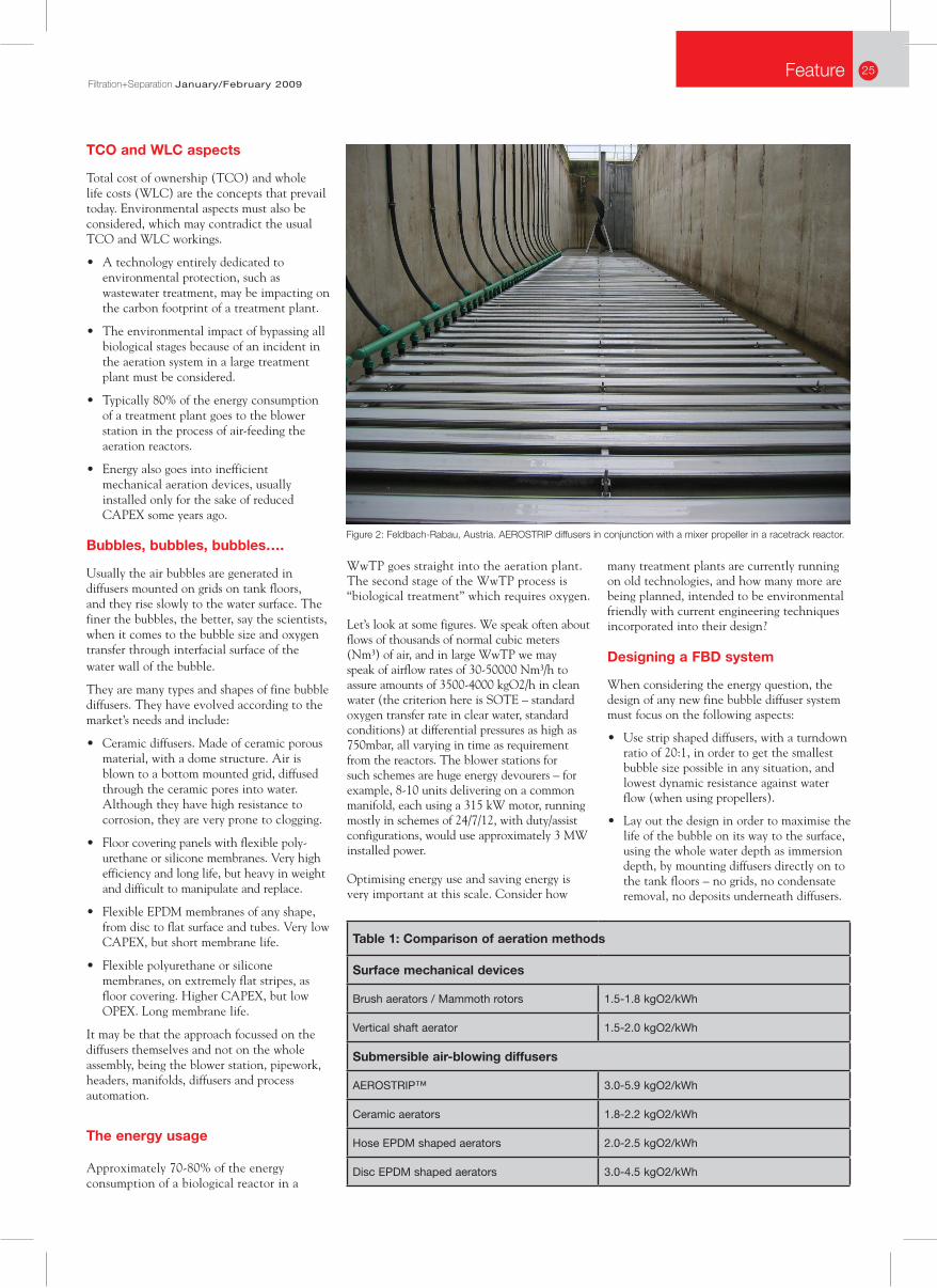
Figure 2: Feldbach-Rabau, Austria. AEROSTRIP diffusers in conjunction with a mixer propeller in a racetrack reactor.

Feature26Filtration+Separation January/February 2009
• Implement preventive maintenance on diffusers into plant logic controllers (flexing and blow down cycles).
• Reduce over-aerating in the tanks, by implementing a fuzzy dissolved oxygen (DO) control, ensuring this is plant and process specific.
• Use positive displacement blowers on VSD (variable speed drive) on common manifolds and adaptive flow control, in order to avoid unwanted waste of energy.
• Use control logic to adapt the operating range of the blowers and diffusers to match their highest efficiency peak.
• Implement bursts in aeration and avoid continuous mixing, as a requirement of minimum airflow for mixing.
The results in terms of energy savings are up to 6.0 kgO2/kWh. Is this high or low? The comparison in Table 1 shows the difference between aeration methods in terms of ranges of SAE (Standard Aeration Efficiency) in normalised conditions. These results have been recorded in different plants and facilities worldwide, and speak mostly about the principle of aeration and not about manufacturers.
The point of the comparison in Table 1 is not how efficient the AEROSTRIP™ diffusers are, but how energy can be saved using the proper technology combined with the best engineering, and treating the system as a whole unit.
Where does energy usually go?
• Energy comes from the power station through distribution lines to the MCC (motor control centre) units.
• Some is lost into transformers, inverters, MCCs, cables, motors.
• The remainder is converted into mechanical energy at the blower shaft.
• Blowers take air and feed the pipe work. They lose energy at the intake filter and inside engine, depending on their concept. Part of the absorbed energy will be delivered as compressed air with a given pressure and airflow rate. Some is lost into heat generation, machine losses, friction on pipework, pressure drops, waves, noise, etc.
• Part of the energy is needed to beat the static pressure of the immersion depth.
• Part of the energy is lost through valves, controlled orifices, etc.
• Another part is used in the aeration device.
• Bubbles with potential energy will be released into water. Kinetic energy is used for suspended solids mixing. Approx 3W/m³ of liquor is needed for mixing.
• The thermal energy of the air is transferred to water.
• Bubbles tend to accelerate to the surface. The lower this speed, the better for oxygen transfer efficiency.
• Any remaining energy is returned to the atmosphere.
We took each of these aspects and adapted our devices to get the most efficiency from them, in order to develop AEROSTRIP™. We also realised that modern inverters allow us to drive blower motors and their shafts at their optimal speeds, as modern controllers may control blowers’ speeds operating on a common manifold as an adaptive source of air, always at peak efficiency.
Facts about AEROSTRIP™:
• Oxygen transfer efficiency of up to 60%.
• Competitive performance through optimal aeration efficiency value – aeration efficiency of up to 5-6 kg O2/kWh
• Diffusers are extremely flat and are strip shaped, allowing installation mostly on the bottom of the tank, at full immersion. This will gain water depth and more travelling time for the bubble on their way to the surface.
• The diffusers do not use EPDM membranes but another type that is perforated without material dislocation, and opens pores gradually as the specific load increases.
• The membranes have a lifespan of 15 years, depending on plant design and operating conditions.
• 20:1 turndown ratio in continuous operation (100 Nm³/hm² / 5 Nm³/hm²).
• Intermittent operation possible (0-100% control of airflow range).
• Coverage. A disc shape generates a theoretical limit of 78% but feasibly can be just a maximum of 39%. AEROSTRIP™ has theoretical coverage of 98% and a feasible coverage of maximum 70%.
• Layout design with flexible lengths and adaptive densities – tapered designs for plug flow schemes always possible.
• Condensate removal systems needed for other systems – not needed for AEROSTRIP™ manifolds.
• Lowest dynamic resistance against water flow (when using propellers).
And the costs?
What are the expenses and savings the client will assess when computing TCO or WLC?
1. CAPEX and OPEX shall be reported up to a life cycle of minimum 10-15 years.
2. Membrane renewal expenses are normal. The frequency of the renewal depends on the manufacturer and method used. There are manufacturers offering systems with a 15 year lifespan, while others offer 2-3 years lifespan (EPDM mostly).
3. Energy expenditures tend to be increasing – therefore there is a need for high efficiency FBD systems.
4. Efficient systems demand less airflow, smaller pipe work sizes and smaller blower units.
5. Maintenance costs get higher when preventive maintenance is ignored and action taken after damage occurs.
6. Initial basic engineering and concept development should be performed by specialists. The tender documents should specify the requirements in clear water for Figure 3: An installation using AEROSTRIPs, at Brescia wastewater treatment plant, Italy.

Feature 27Filtration+Separation January/February 2009
the oxygen demands, and allow impact of the aeration design onto pipework, blower, and I&C (instrumentation and control) subpackages.
It is a common practice to focus on the diffusers themselves and not on the whole assembly. This shall gradually change, and total costs shall be the future target to minimise.
Conclusion
From the manufacturers’ and researchers’ point of view, the following approaches are recommended, which increase the SAE to realistic limits for the industry:
• Reduce over-aerating in the tanks, by implementing a fuzzy dissolved oxygen (DO) control, always plant and process specific.
• Use positive displacement blowers on VSD (variable speed drive) on common manifolds and adaptive flow control, in order to avoid unwanted waste of energy.
• Use control logic to adapt operating range of the blowers and diffusers to match their highest efficiency peak.
• Implementing bursts in aeration and avoid continuous mixing, as a requirement of minimum airflow for mixing.
Readers may think the wasted energy could be recompensated by the production of electricity from biogas in plants with digesters. This was
tried – some energy was still wasted, but costs were lowered due to recycling. However, there remained a high carbon footprint.
We are positive that process engineers will pay more and more attention in saving energy in the future, contributing to the slowing of global warming, minimising carbon footprints and minimising energy use by considering the latest generation of diffusers as best response to this challenge.
The above applies on active sludge wastewater treatment. The multitude of reactors types, shapes, processes and technologies vary from land to land, from continent to continent. •Contact:Adrian Ovezea AQUACONSULT Anlagenbau GmbH Email: [email protected] www.aquaconsult.at
Figure 4: Graph showing the typical curves of SOTE for different immersion depths for strip shaped diffusers AEROSTRIP™