save these instructions - power sentry · installation instructions ... 5. refer to the appropriate...
TRANSCRIPT
INSTALLATION INSTRUCTIONS EMERGENCY FLUORESCENT BATTERY PACK
QD MODELS PS 300 MVOLT, PSQ500 MVOLT, PS600 MVOLT, PS1400 MVOLT
Universal Voltage 120 to 277VAC Input
Page 1
READ AND FOLLOW THESE INSTRUCTIONS BEFORE INSTALLATION TO INSURE PROPER AND SAFE OPERATION
SAVE THESE INSTRUCTIONS FIELD INSTALLABLE FLUORESCENT BATTERY PACK IS UNIVERSALLY COMPATIBLE WITH THE BALLASTS AND LAMP(S) AS SHOWN IN LAMP COMPATIBILITY TABLE (PAGE 5)
READ AND FOLLOW ALL SAFETY INSTRUCTIONS
WARNING
Dual Power Supply - Risk of Shock Hazard Even if AC Power is OFF
Disconnect polarized Test Switch / Pilot Light connector before servicing fixture
DO NOT remove the wire harness connector when AC Power is ON
DO NOT mount near a gas or electric heater
Battery Pack Output Voltage is 1600VDC
CAUTION
Before wiring to power supply, turn off Electricity at fuse panel or circuit breaker
All servicing shall be performed by qualified personnel
DO NOT attempt to service the battery. It is not field replaceable
DO NOT use in hazardous locations
DO NOT use this product outdoors
DO NOT use this product in air handler heated outlets
DO NOT use accessory equipment not recommended by the manufacture
DO NOT use this equipment for other than its intended use
IMPORTANT SAFEGUARDS
Consult your local building code for approved wiring or installation
The emergency battery pack must be connected to an un-switched AC power source of 120 to 277 Vac
This product is for use with indoor fixtures sealed or unsealed
Equipment should be mounted in a location and at heights where it will not be readily be subject to tampering by unauthorized personnel
Make sure that the branch circuits are derived from a common phase for both normal lighting ballast and Battery Pack prior to installation
The Battery Pack can be switched or un-switched (night) circuit. When used with a switched fixture, it is important that the power to the Battery Pack must be provided by an un-switched circuit.
Damage to the battery will occur if the Test Switch / Pilot Light connection is made for a prolonged period of time without AC power being provided.
Battery packs are not field serviceable
Allow Battery Packs to charge 24 hrs before initial and full discharge testing
Do not locate the Test Switch / Pilot Light or route cable within 1” of fixture lamps
Emergency lighting system should be tested per all of the required tests and as often as local codes require or at least quarterly to insure all components are operational.
CONTAINS NICKEL-CADMIUM RECHARGEABLE BATTERY. MUST BE RECYCLED OR DISPOSED OF PROPERLY.
Installation Instructions for Power Sentry Emergency Battery Packs –QD MVOLT Series
Page 2
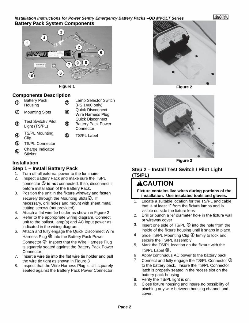
Battery Pack System Components
Figure 1
Components Description
Battery Pack Housing
Lamp Selector Switch (PS 1400 only)
Mounting Slots Quick Disconnect Wire Harness Plug
Test Switch / Pilot Light (TS/PL)
Quick Disconnect Battery Pack Power Connector
TS/PL Mounting Clip TS/PL Label
TS/PL Connector
Charge Indicator Sticker
Installation Step 1 – Install Battery Pack 1. Turn off all external power to the luminaire 2. Inspect Battery Pack and make sure the TSPL
connector is not connected. If so, disconnect it
before installation of the Battery Pack. 3. Position the unit in the fixture wireway and fasten
securely through the Mounting Slots. If
necessary, drill holes and mount with sheet metal cutting screws (not provided)
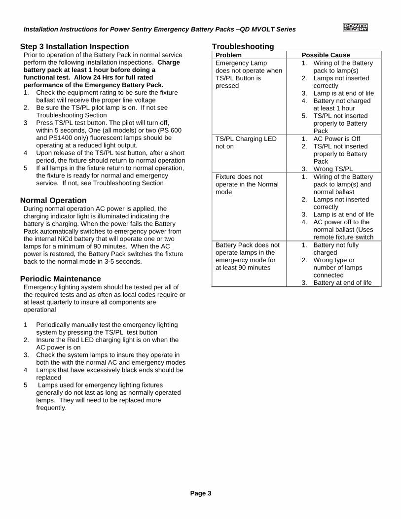
4. Attach a flat wire tie holder as shown in Figure 2 5. Refer to the appropriate wiring diagram, Connect
unit to the ballast, lamp(s) and AC input power as indicated in the wiring diagram.
6. Attach and fully engage the Quick Disconnect Wire
Harness Plug into the Battery Pack Power
Connector Inspect that the Wire Harness Plug
is squarely seated against the Battery Pack Power Connector.
7. Insert a wire tie into the flat wire tie holder and pull the wire tie tight as shown in Figure 3
8. Inspect that the Wire Harness Plug is still squarely seated against the Battery Pack Power Connector.
Figure 2
Figure 3
Step 2 – Install Test Switch / Pilot Light (TS/PL)
CAUTION
Fixture contains live wires during portions of the installation. Use insulated tools and gloves.
1. Locate a suitable location for the TS/PL and cable that is at least 1” from the fixture lamps and is visible outside the fixture lens
2. Drill or punch a ½” diameter hole in the fixture wall or wireway cover
3. Insert one side of TS/PL into the hole from the
inside of the fixture housing until it snaps in place. 4 Slide TS/PL Mounting Clip firmly to lock and
secure the TS/PL assembly 5, Mark the TS/PL location on the fixture with the
TS/PL Label . 6 Apply continuous AC power to the battery pack 7. Connect and fully engage the TS/PL Connector
to the battery pack. Insure the TS/PL Connector latch is properly seated in the recess slot on the battery pack housing
8. Verify the TS/PL light is on. 9. Close fixture housing and insure no possibility of
pinching any wire between housing channel and cover.
Installation Instructions for Power Sentry Emergency Battery Packs –QD MVOLT Series
Page 3
Step 3 Installation Inspection Prior to operation of the Battery Pack in normal service perform the following installation inspections. Charge battery pack at least 1 hour before doing a functional test. Allow 24 Hrs for full rated performance of the Emergency Battery Pack. 1. Check the equipment rating to be sure the fixture
ballast will receive the proper line voltage 2. Be sure the TS/PL pilot lamp is on. If not see
Troubleshooting Section 3 Press TS/PL test button. The pilot will turn off,
within 5 seconds, One (all models) or two (PS 600 and PS1400 only) fluorescent lamps should be operating at a reduced light output.
4 Upon release of the TS/PL test button, after a short period, the fixture should return to normal operation
5 If all lamps in the fixture return to normal operation, the fixture is ready for normal and emergency service. If not, see Troubleshooting Section
Normal Operation During normal operation AC power is applied, the charging indicator light is illuminated indicating the battery is charging. When the power fails the Battery Pack automatically switches to emergency power from the internal NiCd battery that will operate one or two lamps for a minimum of 90 minutes. When the AC power is restored, the Battery Pack switches the fixture back to the normal mode in 3-5 seconds.
Periodic Maintenance Emergency lighting system should be tested per all of the required tests and as often as local codes require or at least quarterly to insure all components are operational 1 Periodically manually test the emergency lighting
system by pressing the TS/PL test button 2. Insure the Red LED charging light is on when the
AC power is on 3. Check the system lamps to insure they operate in
both the with the normal AC and emergency modes 4 Lamps that have excessively black ends should be
replaced 5 Lamps used for emergency lighting fixtures
generally do not last as long as normally operated lamps. They will need to be replaced more frequently.
Troubleshooting Problem Possible Cause
Emergency Lamp does not operate when TS/PL Button is pressed
1. Wiring of the Battery pack to lamp(s)
2. Lamps not inserted correctly
3. Lamp is at end of life 4. Battery not charged
at least 1 hour 5. TS/PL not inserted
properly to Battery Pack
TS/PL Charging LED not on
1. AC Power is Off 2. TS/PL not inserted
properly to Battery Pack
3. Wrong TS/PL
Fixture does not operate in the Normal mode
1. Wiring of the Battery pack to lamp(s) and normal ballast
2. Lamps not inserted correctly
3. Lamp is at end of life 4. AC power off to the
normal ballast (Uses remote fixture switch
Battery Pack does not operate lamps in the emergency mode for at least 90 minutes
1. Battery not fully charged
2. Wrong type or number of lamps connected
3. Battery at end of life
Installation Instructions for Power Sentry Emergency Battery Packs –QD MVOLT Series
Page 4
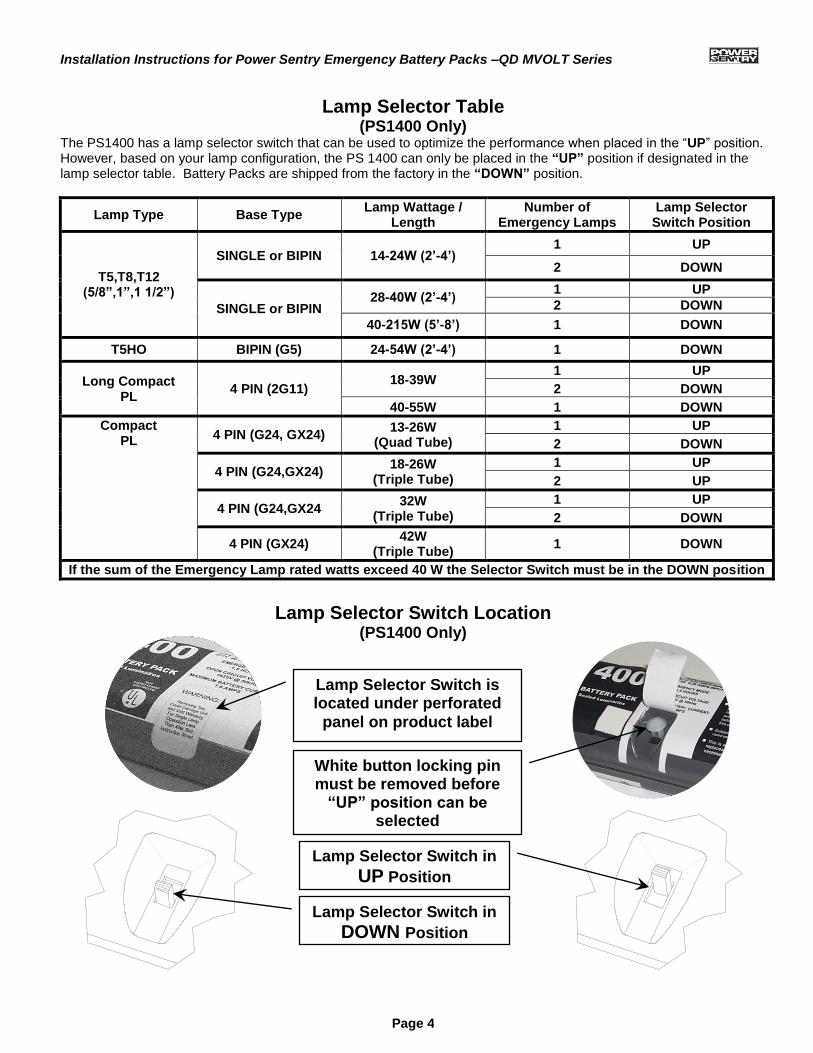
Lamp Selector Table (PS1400 Only)
The PS1400 has a lamp selector switch that can be used to optimize the performance when placed in the “UP” position. However, based on your lamp configuration, the PS 1400 can only be placed in the “UP” position if designated in the lamp selector table. Battery Packs are shipped from the factory in the “DOWN” position.
Lamp Type Base Type Lamp Wattage /
Length Number of
Emergency Lamps Lamp Selector
Switch Position
T5,T8,T12 (5/8”,1”,1 1/2”)
SINGLE or BIPIN 14-24W (2’-4’) 1 UP
2 DOWN
SINGLE or BIPIN 28-40W (2’-4’)
1 UP
2 DOWN
40-215W (5’-8’) 1 DOWN
T5HO BIPIN (G5) 24-54W (2’-4’) 1 DOWN
Long Compact PL
4 PIN (2G11) 18-39W
1 UP
2 DOWN
40-55W 1 DOWN
Compact PL 4 PIN (G24, GX24)
13-26W (Quad Tube)
1 UP
2 DOWN
4 PIN (G24,GX24) 18-26W
(Triple Tube)
1 UP
2 UP
4 PIN (G24,GX24 32W
(Triple Tube)
1 UP
2 DOWN
4 PIN (GX24) 42W
(Triple Tube) 1 DOWN
If the sum of the Emergency Lamp rated watts exceed 40 W the Selector Switch must be in the DOWN position
Lamp Selector Switch Location
(PS1400 Only)
Lamp Selector Switch is located under perforated
panel on product label
White button locking pin must be removed before
“UP” position can be selected
Lamp Selector Switch in
UP Position
Lamp Selector Switch in
DOWN Position
Installation Instructions for Power Sentry Emergency Battery Packs –QD MVOLT Series
Page 5
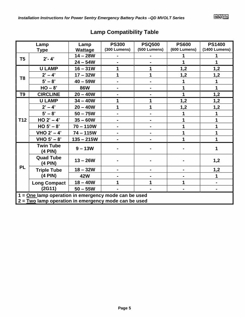
Lamp Compatibility Table
Lamp Type
Lamp Wattage
PS300 (300 Lumens)
PSQ500 (500 Lumens)
PS600 (600 Lumens)
PS1400 (1400 Lumens)
T5 2’- 4’ 14 – 28W - - 1 1
24 – 54W - - 1 1
T8
U LAMP 16 – 31W 1 1 1,2 1,2
2’ – 4’ 17 – 32W 1 1 1,2 1,2
5’ – 8’ 40 – 59W - - 1 1
HO – 8’ 86W - - 1 1
T9 CIRCLINE 20 – 40W - - 1 1,2
T12
U LAMP 34 – 40W 1 1 1,2 1,2
2’ – 4’ 20 – 40W 1 1 1,2 1,2
5’ – 8’ 50 – 75W - - 1 1
HO 2’ – 4’ 35 – 60W - - 1 1
HO 5’ – 8’ 70 – 110W - - 1 1
VHO 2’ – 4’ 74 – 115W - - 1 1
VHO 5’ – 8’ 135 – 215W - - 1 1
PL
Twin Tube (4 PIN)
9 – 13W - - - 1
Quad Tube (4 PIN)
13 – 26W - - - 1,2
Triple Tube (4 PIN)
18 – 32W - - - 1,2
42W - - - 1
Long Compact (2G11)
18 – 40W 1 1 1 -
50 – 55W - - - -
1 = One lamp operation in emergency mode can be used 2 = Two lamp operation in emergency mode can be used
Installation Instructions for Power Sentry Emergency Battery Packs –QD MVOLT Series
Page 6
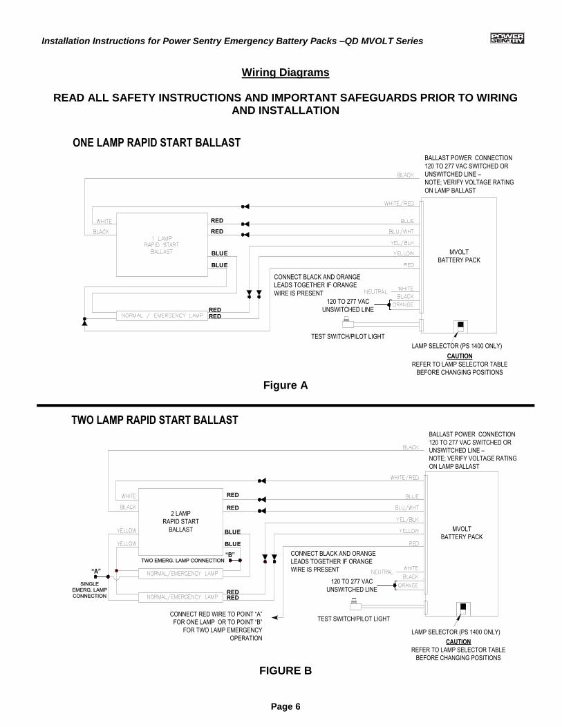
Wiring Diagrams
READ ALL SAFETY INSTRUCTIONS AND IMPORTANT SAFEGUARDS PRIOR TO WIRING AND INSTALLATION
BALLAST POWER CONNECTION
120 TO 277 VAC SWITCHED OR
UNSWITCHED LINE –
NOTE; VERIFY VOLTAGE RATING
ON LAMP BALLAST
LAMP SELECTOR (PS 1400 ONLY)
CAUTION
REFER TO LAMP SELECTOR TABLE
BEFORE CHANGING POSITIONS
CONNECT BLACK AND ORANGE
LEADS TOGETHER IF ORANGE
WIRE IS PRESENT
TEST SWITCH/PILOT LIGHT
120 TO 277 VAC
UNSWITCHED LINE
MVOLT
BATTERY PACK
ONE LAMP RAPID START BALLAST
RED
BLUE
BLUE
REDRED
RED
Figure A
TWO LAMP RAPID START BALLAST
SINGLE
EMERG. LAMP
CONNECTION
CONNECT RED WIRE TO POINT “A”
FOR ONE LAMP OR TO POINT “B”
FOR TWO LAMP EMERGENCY
OPERATION
CONNECT BLACK AND ORANGE
LEADS TOGETHER IF ORANGE
WIRE IS PRESENT
120 TO 277 VAC
UNSWITCHED LINE
BALLAST POWER CONNECTION
120 TO 277 VAC SWITCHED OR
UNSWITCHED LINE –
NOTE; VERIFY VOLTAGE RATING
ON LAMP BALLAST
LAMP SELECTOR (PS 1400 ONLY)
CAUTION
REFER TO LAMP SELECTOR TABLE
BEFORE CHANGING POSITIONS
TWO EMERG. LAMP CONNECTION“B”
“A”
MVOLT
BATTERY PACK
2 LAMP
RAPID START
BALLAST
TEST SWITCH/PILOT LIGHT
RED
RED
REDRED
BLUE
BLUE
FIGURE B
Installation Instructions for Power Sentry Emergency Battery Packs –QD MVOLT Series
Page 7
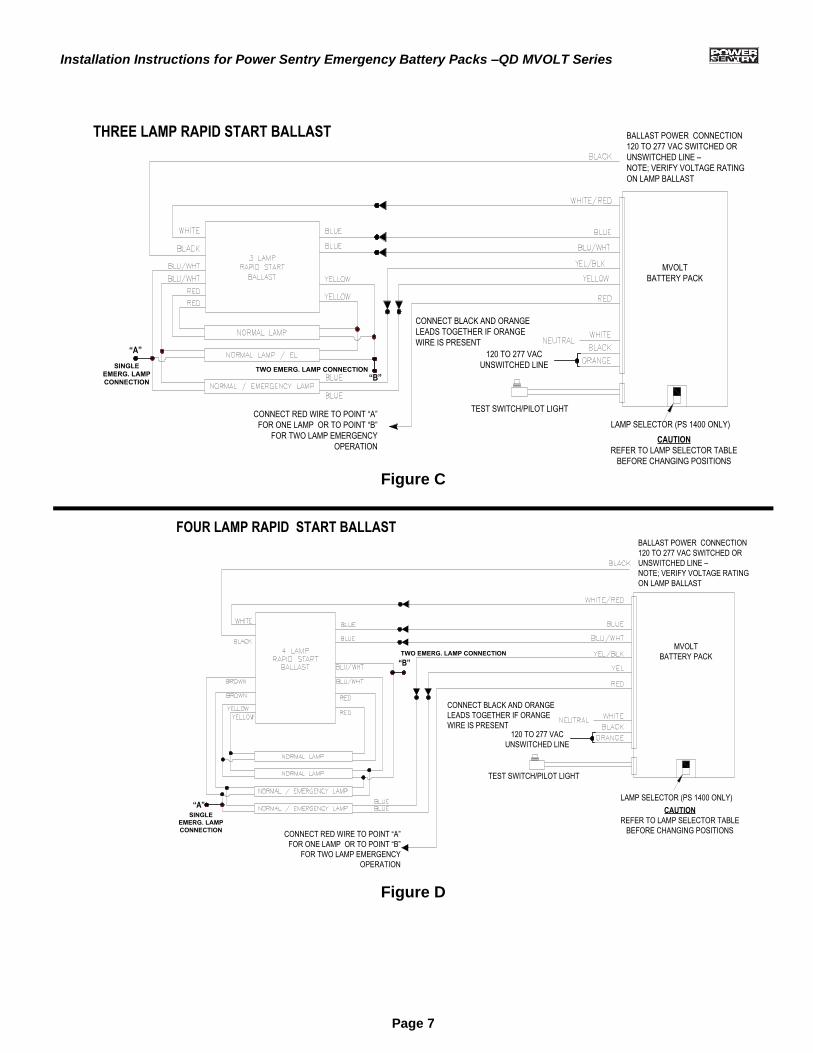
CONNECT RED WIRE TO POINT “A”
FOR ONE LAMP OR TO POINT “B”
FOR TWO LAMP EMERGENCY
OPERATIONCAUTION
REFER TO LAMP SELECTOR TABLE
BEFORE CHANGING POSITIONS
LAMP SELECTOR (PS 1400 ONLY)
BALLAST POWER CONNECTION
120 TO 277 VAC SWITCHED OR
UNSWITCHED LINE –
NOTE; VERIFY VOLTAGE RATING
ON LAMP BALLAST
CONNECT BLACK AND ORANGE
LEADS TOGETHER IF ORANGE
WIRE IS PRESENT
120 TO 277 VAC
UNSWITCHED LINE
TEST SWITCH/PILOT LIGHT
SINGLE
EMERG. LAMP
CONNECTION
“A”
TWO EMERG. LAMP CONNECTION
“B”
MVOLT
BATTERY PACK
THREE LAMP RAPID START BALLAST
Figure C
FOUR LAMP RAPID START BALLAST
SINGLE
EMERG. LAMP
CONNECTION
“A”
“B”
TWO EMERG. LAMP CONNECTION
CONNECT RED WIRE TO POINT “A”
FOR ONE LAMP OR TO POINT “B”
FOR TWO LAMP EMERGENCY
OPERATION
BALLAST POWER CONNECTION
120 TO 277 VAC SWITCHED OR
UNSWITCHED LINE –
NOTE; VERIFY VOLTAGE RATING
ON LAMP BALLAST
CONNECT BLACK AND ORANGE
LEADS TOGETHER IF ORANGE
WIRE IS PRESENT120 TO 277 VAC
UNSWITCHED LINE
LAMP SELECTOR (PS 1400 ONLY)
CAUTION
REFER TO LAMP SELECTOR TABLE
BEFORE CHANGING POSITIONS
MVOLT
BATTERY PACK
TEST SWITCH/PILOT LIGHT
Figure D
Installation Instructions for Power Sentry Emergency Battery Packs –QD MVOLT Series
Page 8
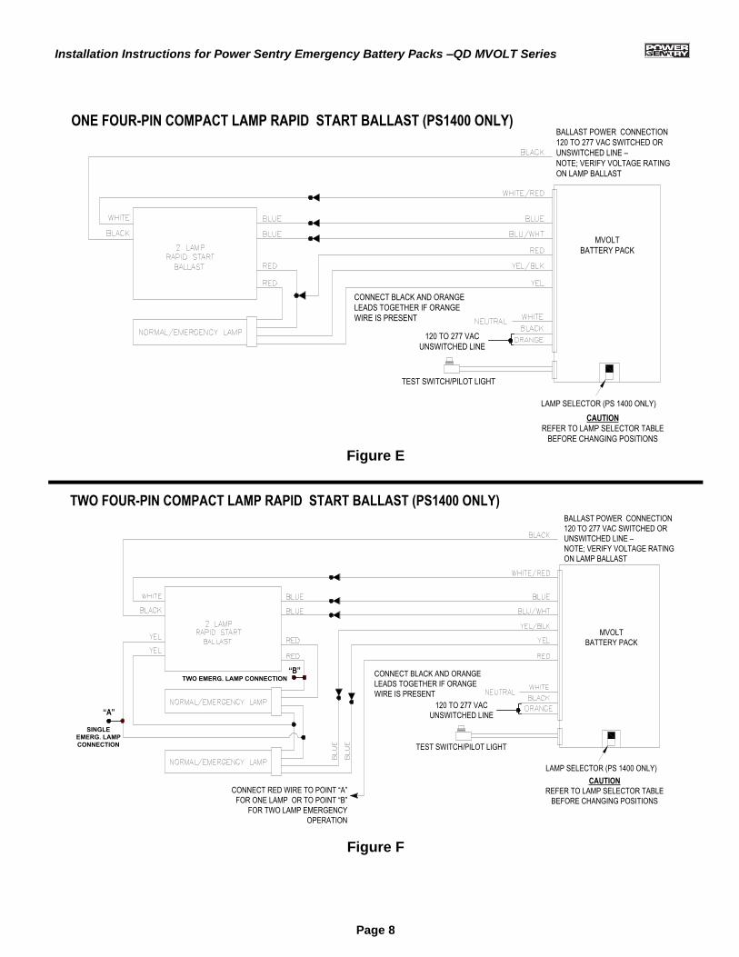
ONE FOUR-PIN COMPACT LAMP RAPID START BALLAST (PS1400 ONLY)
CAUTION
REFER TO LAMP SELECTOR TABLE
BEFORE CHANGING POSITIONS
LAMP SELECTOR (PS 1400 ONLY)
TEST SWITCH/PILOT LIGHT
CONNECT BLACK AND ORANGE
LEADS TOGETHER IF ORANGE
WIRE IS PRESENT
BALLAST POWER CONNECTION
120 TO 277 VAC SWITCHED OR
UNSWITCHED LINE –
NOTE; VERIFY VOLTAGE RATING
ON LAMP BALLAST
120 TO 277 VAC
UNSWITCHED LINE
MVOLT
BATTERY PACK
Figure E
CAUTION
REFER TO LAMP SELECTOR TABLE
BEFORE CHANGING POSITIONS
LAMP SELECTOR (PS 1400 ONLY)
TEST SWITCH/PILOT LIGHT
CONNECT BLACK AND ORANGE
LEADS TOGETHER IF ORANGE
WIRE IS PRESENT
120 TO 277 VAC
UNSWITCHED LINE
MVOLT
BATTERY PACK
BALLAST POWER CONNECTION
120 TO 277 VAC SWITCHED OR
UNSWITCHED LINE –
NOTE; VERIFY VOLTAGE RATING
ON LAMP BALLAST
TWO FOUR-PIN COMPACT LAMP RAPID START BALLAST (PS1400 ONLY)
CONNECT RED WIRE TO POINT “A”
FOR ONE LAMP OR TO POINT “B”
FOR TWO LAMP EMERGENCY
OPERATION
SINGLE
EMERG. LAMP
CONNECTION
“A”
TWO EMERG. LAMP CONNECTION
“B”
Figure F
Installation Instructions for Power Sentry Emergency Battery Packs –QD MVOLT Series
Page 9
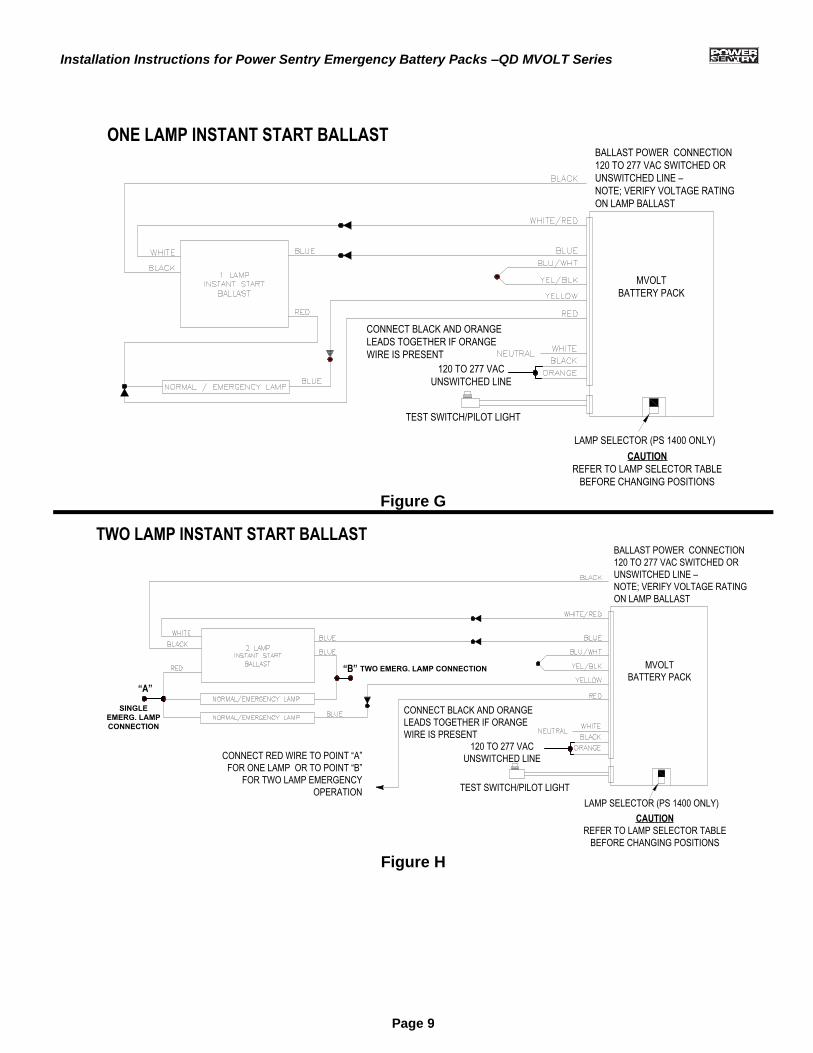
CAUTION
REFER TO LAMP SELECTOR TABLE
BEFORE CHANGING POSITIONS
LAMP SELECTOR (PS 1400 ONLY)
TEST SWITCH/PILOT LIGHT
CONNECT BLACK AND ORANGE
LEADS TOGETHER IF ORANGE
WIRE IS PRESENT
120 TO 277 VAC
UNSWITCHED LINE
BALLAST POWER CONNECTION
120 TO 277 VAC SWITCHED OR
UNSWITCHED LINE –
NOTE; VERIFY VOLTAGE RATING
ON LAMP BALLAST
MVOLT
BATTERY PACK
ONE LAMP INSTANT START BALLAST
Figure G
CONNECT BLACK AND ORANGE
LEADS TOGETHER IF ORANGE
WIRE IS PRESENT
CONNECT RED WIRE TO POINT “A”
FOR ONE LAMP OR TO POINT “B”
FOR TWO LAMP EMERGENCY
OPERATION
CAUTION
REFER TO LAMP SELECTOR TABLE
BEFORE CHANGING POSITIONS
LAMP SELECTOR (PS 1400 ONLY)
TEST SWITCH/PILOT LIGHT
120 TO 277 VAC
UNSWITCHED LINE
MVOLT
BATTERY PACK
BALLAST POWER CONNECTION
120 TO 277 VAC SWITCHED OR
UNSWITCHED LINE –
NOTE; VERIFY VOLTAGE RATING
ON LAMP BALLAST
“A”
SINGLE
EMERG. LAMP
CONNECTION
“B” TWO EMERG. LAMP CONNECTION
TWO LAMP INSTANT START BALLAST
Figure H
Installation Instructions for Power Sentry Emergency Battery Packs –QD MVOLT Series
Page 10
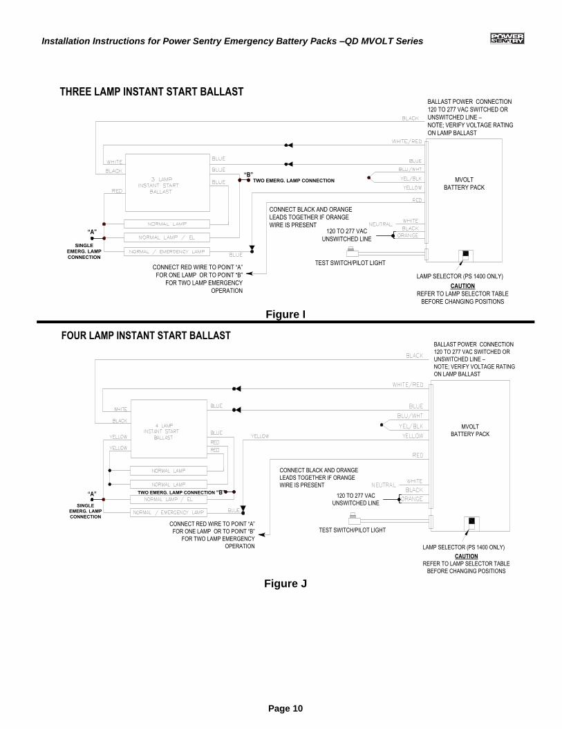
CONNECT RED WIRE TO POINT “A”
FOR ONE LAMP OR TO POINT “B”
FOR TWO LAMP EMERGENCY
OPERATION
CONNECT BLACK AND ORANGE
LEADS TOGETHER IF ORANGE
WIRE IS PRESENT120 TO 277 VAC
UNSWITCHED LINE
TEST SWITCH/PILOT LIGHT
CAUTION
REFER TO LAMP SELECTOR TABLE
BEFORE CHANGING POSITIONS
LAMP SELECTOR (PS 1400 ONLY)
BALLAST POWER CONNECTION
120 TO 277 VAC SWITCHED OR
UNSWITCHED LINE –
NOTE; VERIFY VOLTAGE RATING
ON LAMP BALLAST
SINGLE
EMERG. LAMP
CONNECTION
“A”
“B” TWO EMERG. LAMP CONNECTION MVOLT
BATTERY PACK
THREE LAMP INSTANT START BALLAST
Figure I
CONNECT RED WIRE TO POINT “A”
FOR ONE LAMP OR TO POINT “B”
FOR TWO LAMP EMERGENCY
OPERATION
SINGLE
EMERG. LAMP
CONNECTION
“A” TWO EMERG. LAMP CONNECTION “B”
CONNECT BLACK AND ORANGE
LEADS TOGETHER IF ORANGE
WIRE IS PRESENT
TEST SWITCH/PILOT LIGHT
120 TO 277 VAC
UNSWITCHED LINE
CAUTION
REFER TO LAMP SELECTOR TABLE
BEFORE CHANGING POSITIONS
LAMP SELECTOR (PS 1400 ONLY)
MVOLT
BATTERY PACK
FOUR LAMP INSTANT START BALLASTBALLAST POWER CONNECTION
120 TO 277 VAC SWITCHED OR
UNSWITCHED LINE –
NOTE; VERIFY VOLTAGE RATING
ON LAMP BALLAST
Figure J
Installation Instructions for Power Sentry Emergency Battery Packs –QD MVOLT Series
Page 11
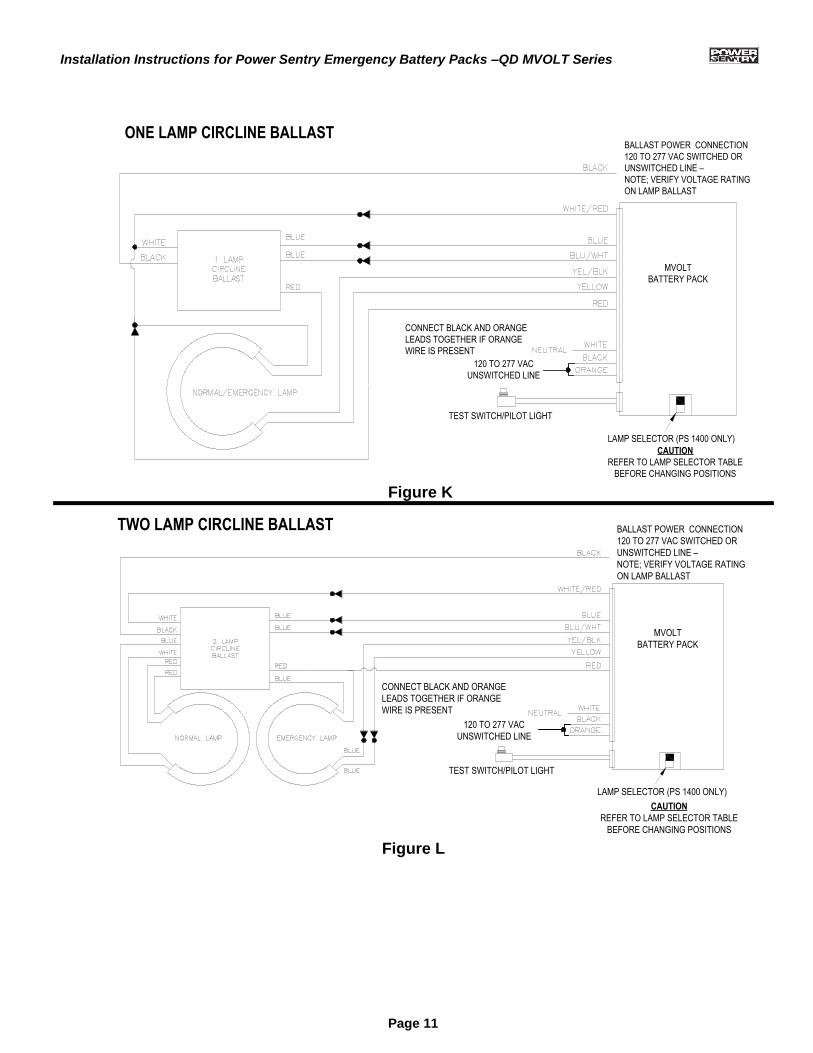
CAUTION
REFER TO LAMP SELECTOR TABLE
BEFORE CHANGING POSITIONS
LAMP SELECTOR (PS 1400 ONLY)
BALLAST POWER CONNECTION
120 TO 277 VAC SWITCHED OR
UNSWITCHED LINE –
NOTE; VERIFY VOLTAGE RATING
ON LAMP BALLAST
CONNECT BLACK AND ORANGE
LEADS TOGETHER IF ORANGE
WIRE IS PRESENT
120 TO 277 VAC
UNSWITCHED LINE
TEST SWITCH/PILOT LIGHT
MVOLT
BATTERY PACK
ONE LAMP CIRCLINE BALLAST
Figure K
LAMP SELECTOR (PS 1400 ONLY)
CAUTION
REFER TO LAMP SELECTOR TABLE
BEFORE CHANGING POSITIONS
TEST SWITCH/PILOT LIGHT
BALLAST POWER CONNECTION
120 TO 277 VAC SWITCHED OR
UNSWITCHED LINE –
NOTE; VERIFY VOLTAGE RATING
ON LAMP BALLAST
CONNECT BLACK AND ORANGE
LEADS TOGETHER IF ORANGE
WIRE IS PRESENT
120 TO 277 VAC
UNSWITCHED LINE
TWO LAMP CIRCLINE BALLAST
MVOLT
BATTERY PACK
Figure L
Installation Instructions for Power Sentry Emergency Battery Packs –QD MVOLT Series
Page 12
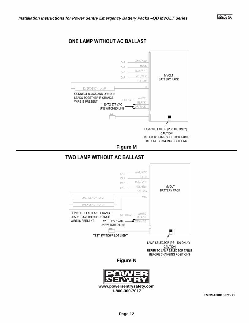
LAMP SELECTOR (PS 1400 ONLY)
CAUTION
REFER TO LAMP SELECTOR TABLE
BEFORE CHANGING POSITIONS
CONNECT BLACK AND ORANGE
LEADS TOGETHER IF ORANGE
WIRE IS PRESENT120 TO 277 VAC
UNSWITCHED LINE
MVOLT
BATTERY PACK
ONE LAMP WITHOUT AC BALLAST
Figure M
CAUTION
REFER TO LAMP SELECTOR TABLE
BEFORE CHANGING POSITIONS
LAMP SELECTOR (PS 1400 ONLY)
CONNECT BLACK AND ORANGE
LEADS TOGETHER IF ORANGE
WIRE IS PRESENT 120 TO 277 VAC
UNSWITCHED LINE
TEST SWITCH/PILOT LIGHT
TWO LAMP WITHOUT AC BALLAST
MVOLT
BATTERY PACK
Figure N
www.powersentrysafety.com
1-800-300-7017 EMCSA00813 Rev C