save these instructions for future use! modulating
TRANSCRIPT
Installation 2Wiring Connections 2Thermostat Quick Reference 3Installer Configuration Menu 4Operating Your Thermostat 7Programming 7Troubleshooting 11
PART NO. 37-6768A
0626
Installation and Operating Instructions forModulating Touchscreen Thermostat
APPLICATIONS
Description
Heat Pump (with Aux. or Emergency Heat), 2 Stage YesSystems with up to 3 Stages Heat, 2 Stages Cool YesHeat Only Systems YesWired Remote Temperature Sensor (Indoor/Outdoor) YesDual Fuel Feature (Heat Pump Mode) YesModulating PWM output, gas furnace Yes
THERMOSTAT APPLICATION GUIDE
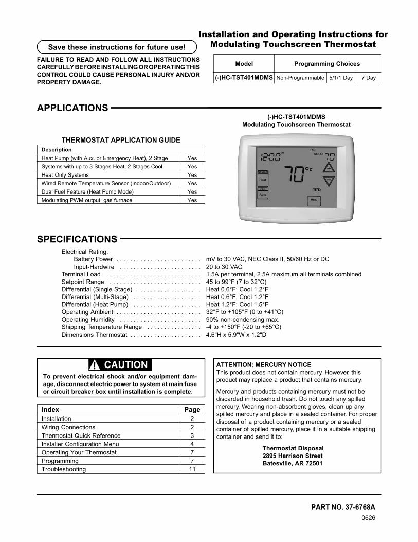
(-)HC-TST401MDMSModulating Touchscreen Thermostat
SPECIFICATIONSElectrical Rating:
Battery Power . . . . . . . . . . . . . . . . . . . . . . . . . mV to 30 VAC, NEC Class II, 50/60 Hz or DCInput-Hardwire . . . . . . . . . . . . . . . . . . . . . . . . 20 to 30 VAC
Terminal Load . . . . . . . . . . . . . . . . . . . . . . . . . . . . 1.5A per terminal, 2.5A maximum all terminals combinedSetpoint Range . . . . . . . . . . . . . . . . . . . . . . . . . . . 45 to 99°F (7 to 32°C)Differential (Single Stage) . . . . . . . . . . . . . . . . . . . Heat 0.6°F; Cool 1.2°FDifferential (Multi-Stage) . . . . . . . . . . . . . . . . . . . . Heat 0.6°F; Cool 1.2°FDifferential (Heat Pump) . . . . . . . . . . . . . . . . . . . . Heat 1.2°F; Cool 1.5°FOperating Ambient . . . . . . . . . . . . . . . . . . . . . . . . . 32°F to +105°F (0 to +41°C)Operating Humidity . . . . . . . . . . . . . . . . . . . . . . . . 90% non-condensing max.Shipping Temperature Range . . . . . . . . . . . . . . . . -4 to +150°F (-20 to +65°C)Dimensions Thermostat . . . . . . . . . . . . . . . . . . . . . 4.6"H x 5.9"W x 1.2"D
To prevent electrical shock and/or equipment dam-age, disconnect electric power to system at main fuseor circuit breaker box until installation is complete.
CAUTION! ATTENTION: MERCURY NOTICEThis product does not contain mercury. However, thisproduct may replace a product that contains mercury.
Mercury and products containing mercury must not bediscarded in household trash. Do not touch any spilledmercury. Wearing non-absorbent gloves, clean up anyspilled mercury and place in a sealed container. For properdisposal of a product containing mercury or a sealedcontainer of spilled mercury, place it in a suitable shippingcontainer and send it to:
Thermostat Disposal2895 Harrison StreetBatesville, AR 72501
Index Page
Model Programming Choices
(-)HC-TST401MDMS Non-Programmable 5/1/1 Day 7 Day
Save these instructions for future use!
FAILURE TO READ AND FOLLOW ALL INSTRUCTIONSCAREFULLY BEFORE INSTALLING OR OPERATING THISCONTROL COULD CAUSE PERSONAL INJURY AND/ORPROPERTY DAMAGE.
2
2 "AA" Batteries
WIRING CONNECTIONSRefer to equipment manufacturers' instructions for specificsystem wiring information. After wiring, see CONFIGURA-TION section for proper thermostat configuration.
For wiring diagrams, see 37-6808A.Wiring diagrams shown are for typical systems and describethe thermostat terminal functions.
WARNING!Thermostat installation and all components of thecontrol system shall conform to Class II circuits perthe NEC code.
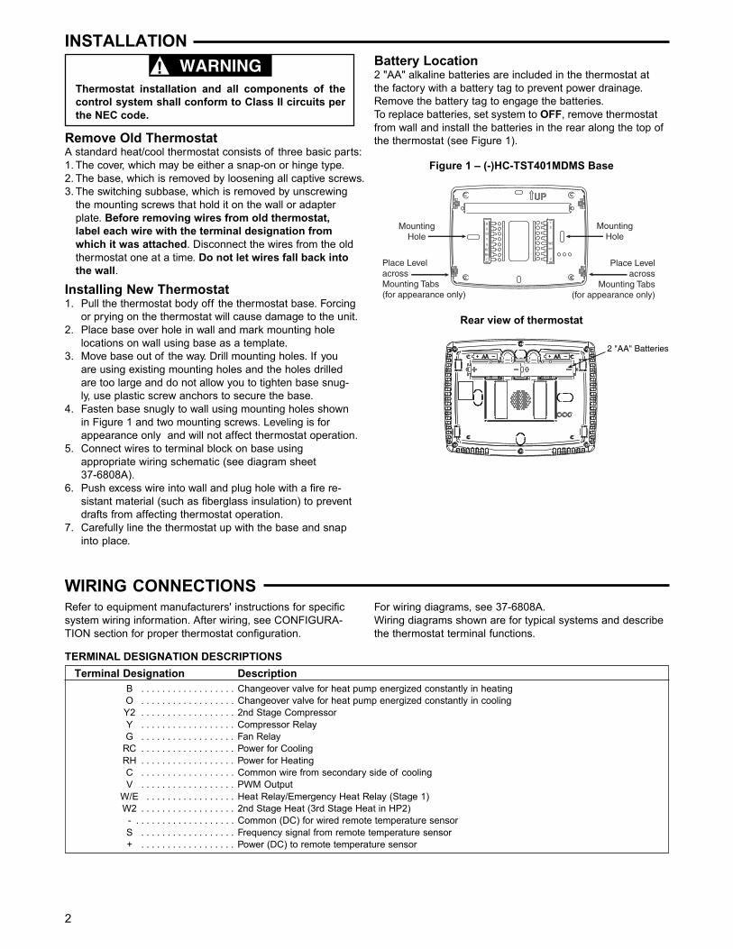
INSTALLATIONBattery Location2 "AA" alkaline batteries are included in the thermostat atthe factory with a battery tag to prevent power drainage.Remove the battery tag to engage the batteries.To replace batteries, set system to OFF, remove thermostatfrom wall and install the batteries in the rear along the top ofthe thermostat (see Figure 1).Remove Old Thermostat
A standard heat/cool thermostat consists of three basic parts:1. The cover, which may be either a snap-on or hinge type.2. The base, which is removed by loosening all captive screws.3. The switching subbase, which is removed by unscrewing
the mounting screws that hold it on the wall or adapterplate. Before removing wires from old thermostat,label each wire with the terminal designation fromwhich it was attached. Disconnect the wires from the oldthermostat one at a time. Do not let wires fall back intothe wall.
Installing New Thermostat1. Pull the thermostat body off the thermostat base. Forcing
or prying on the thermostat will cause damage to the unit.2. Place base over hole in wall and mark mounting hole
locations on wall using base as a template.3. Move base out of the way. Drill mounting holes. If you
are using existing mounting holes and the holes drilledare too large and do not allow you to tighten base snug-ly, use plastic screw anchors to secure the base.
4. Fasten base snugly to wall using mounting holes shownin Figure 1 and two mounting screws. Leveling is forappearance only and will not affect thermostat operation.
5. Connect wires to terminal block on base usingappropriate wiring schematic (see diagram sheet37-6808A).
6. Push excess wire into wall and plug hole with a fire re-sistant material (such as fiberglass insulation) to preventdrafts from affecting thermostat operation.
7. Carefully line the thermostat up with the base and snapinto place.
Terminal Designation DescriptionB . . . . . . . . . . . . . . . . . . Changeover valve for heat pump energized constantly in heatingO . . . . . . . . . . . . . . . . . . Changeover valve for heat pump energized constantly in coolingY2 . . . . . . . . . . . . . . . . . . 2nd Stage CompressorY . . . . . . . . . . . . . . . . . . Compressor RelayG . . . . . . . . . . . . . . . . . . Fan Relay
RC . . . . . . . . . . . . . . . . . . Power for CoolingRH . . . . . . . . . . . . . . . . . . Power for HeatingC . . . . . . . . . . . . . . . . . . Common wire from secondary side of coolingV . . . . . . . . . . . . . . . . . . PWM Output
W/E . . . . . . . . . . . . . . . . . Heat Relay/Emergency Heat Relay (Stage 1)W2 . . . . . . . . . . . . . . . . . . 2nd Stage Heat (3rd Stage Heat in HP2)
- . . . . . . . . . . . . . . . . . . . Common (DC) for wired remote temperature sensorS . . . . . . . . . . . . . . . . . . Frequency signal from remote temperature sensor+ . . . . . . . . . . . . . . . . . . Power (DC) to remote temperature sensor
TERMINAL DESIGNATION DESCRIPTIONS
MountingHole
MountingHole
Place LevelacrossMounting Tabs(for appearance only)
Place Levelacross
Mounting Tabs(for appearance only)
+
S
-
W/E
V
Y2
W2
Figure 1 – (-)HC-TST401MDMS Base
Rear view of thermostat
3
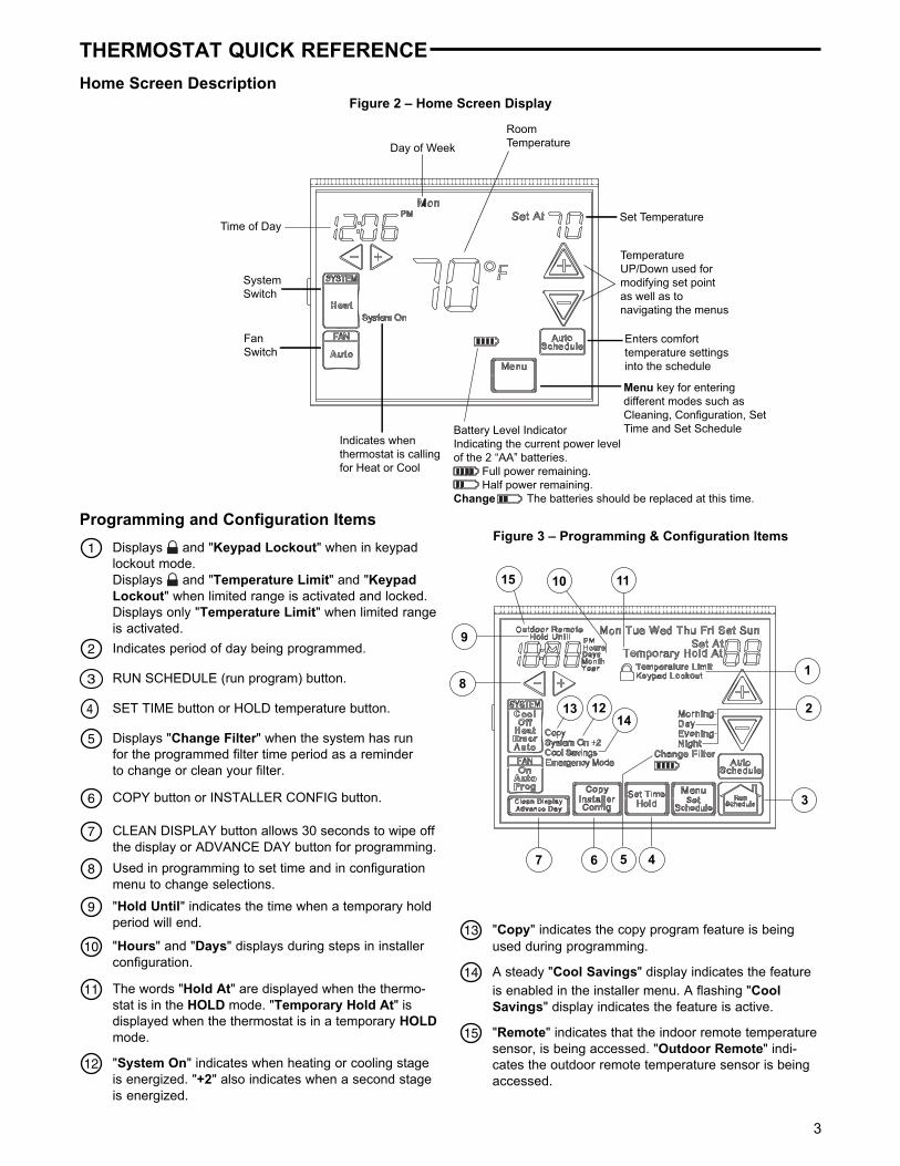
Time of Day
Day of WeekRoomTemperature
SystemSwitch
FanSwitch
Indicates whenthermostat is callingfor Heat or Cool
Battery Level IndicatorIndicating the current power levelof the 2 “AA” batteries. Full power remaining. Half power remaining.Change The batteries should be replaced at this time.
Menu key for enteringdifferent modes such asCleaning, Configuration, SetTime and Set Schedule
Enters comforttemperature settingsinto the schedule
TemperatureUP/Down used formodifying set pointas well as tonavigating the menus
Set Temperature
THERMOSTAT QUICK REFERENCE
Home Screen DescriptionFigure 2 – Home Screen Display
13 "Copy" indicates the copy program feature is beingused during programming.
14 A steady "Cool Savings" display indicates the featureis enabled in the installer menu. A flashing "CoolSavings" display indicates the feature is active.
12 "System On" indicates when heating or cooling stageis energized. "+2" also indicates when a second stageis energized.
11 The words "Hold At" are displayed when the thermo-stat is in the HOLD mode. "Temporary Hold At" isdisplayed when the thermostat is in a temporary HOLDmode.
10 "Hours" and "Days" displays during steps in installerconfiguration.
9 "Hold Until" indicates the time when a temporary holdperiod will end.
8 Used in programming to set time and in configurationmenu to change selections.
7 CLEAN DISPLAY button allows 30 seconds to wipe offthe display or ADVANCE DAY button for programming.
6 COPY button or INSTALLER CONFIG button.
5 Displays "Change Filter" when the system has runfor the programmed filter time period as a reminderto change or clean your filter.
2 Indicates period of day being programmed.
3 RUN SCHEDULE (run program) button.
4 SET TIME button or HOLD temperature button.
1 Displays and "Keypad Lockout" when in keypadlockout mode.Displays and "Temperature Limit" and "KeypadLockout" when limited range is activated and locked.Displays only "Temperature Limit" when limited rangeis activated.
Programming and Configuration ItemsFigure 3 – Programming & Configuration Items
15 "Remote" indicates that the indoor remote temperaturesensor, is being accessed. "Outdoor Remote" indi-cates the outdoor remote temperature sensor is beingaccessed.
15
1413 12
1110
9
8
7 6 5 4
3
2
1
4
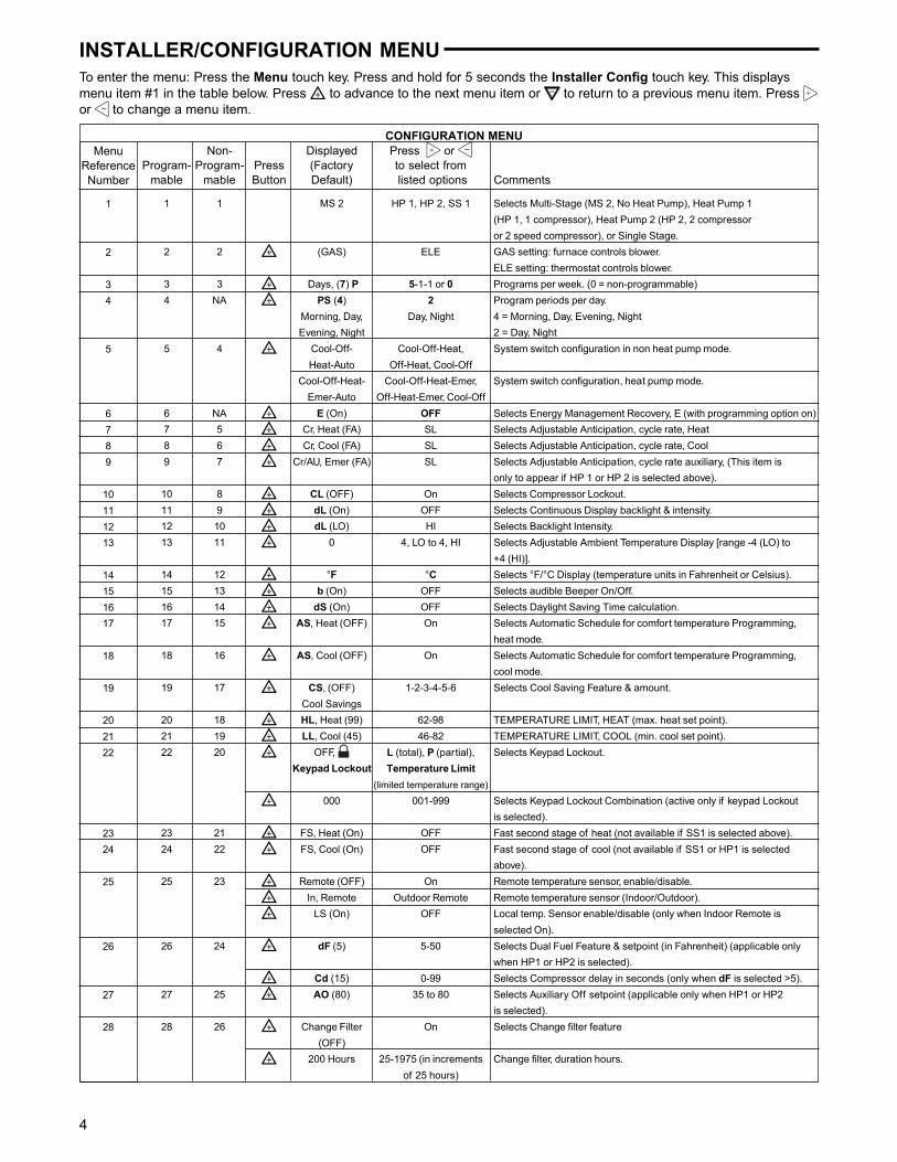
CONFIGURATION MENUNon- Displayed Press or
Program- Program- Press (Factory to select frommable mable Button Default) listed options Comments
1 1 MS 2 HP 1, HP 2, SS 1 Selects Multi-Stage (MS 2, No Heat Pump), Heat Pump 1(HP 1, 1 compressor), Heat Pump 2 (HP 2, 2 compressoror 2 speed compressor), or Single Stage.
2 2 (GAS) ELE GAS setting: furnace controls blower.ELE setting: thermostat controls blower.
3 3 Days, (7) P 5-1-1 or 0 Programs per week. (0 = non-programmable)4 NA PS (4) 2 Program periods per day.
Morning, Day, Day, Night 4 = Morning, Day, Evening, NightEvening, Night 2 = Day, Night
5 4 Cool-Off- Cool-Off-Heat, System switch configuration in non heat pump mode.Heat-Auto Off-Heat, Cool-Off
Cool-Off-Heat- Cool-Off-Heat-Emer, System switch configuration, heat pump mode.Emer-Auto Off-Heat-Emer, Cool-Off
6 NA E (On) OFF Selects Energy Management Recovery, E (with programming option on)7 5 Cr, Heat (FA) SL Selects Adjustable Anticipation, cycle rate, Heat8 6 Cr, Cool (FA) SL Selects Adjustable Anticipation, cycle rate, Cool9 7 Cr/AU, Emer (FA) SL Selects Adjustable Anticipation, cycle rate auxiliary, (This item is
only to appear if HP 1 or HP 2 is selected above).10 8 CL (OFF) On Selects Compressor Lockout.11 9 dL (On) OFF Selects Continuous Display backlight & intensity.12 10 dL (LO) HI Selects Backlight Intensity.13 11 0 4, LO to 4, HI Selects Adjustable Ambient Temperature Display [range -4 (LO) to
+4 (HI)].14 12 °F °C Selects °F/°C Display (temperature units in Fahrenheit or Celsius).15 13 b (On) OFF Selects audible Beeper On/Off.16 14 dS (On) OFF Selects Daylight Saving Time calculation.17 15 AS, Heat (OFF) On Selects Automatic Schedule for comfort temperature Programming,
heat mode.18 16 AS, Cool (OFF) On Selects Automatic Schedule for comfort temperature Programming,
cool mode.19 17 CS, (OFF) 1-2-3-4-5-6 Selects Cool Saving Feature & amount.
Cool Savings20 18 HL, Heat (99) 62-98 TEMPERATURE LIMIT, HEAT (max. heat set point).21 19 LL, Cool (45) 46-82 TEMPERATURE LIMIT, COOL (min. cool set point).22 20 OFF, L (total), P (partial), Selects Keypad Lockout.
Keypad Lockout Temperature Limit
(limited temperature range)
000 001-999 Selects Keypad Lockout Combination (active only if keypad Lockoutis selected).
23 21 FS, Heat (On) OFF Fast second stage of heat (not available if SS1 is selected above).24 22 FS, Cool (On) OFF Fast second stage of cool (not available if SS1 or HP1 is selected
above).25 23 Remote (OFF) On Remote temperature sensor, enable/disable.
In, Remote Outdoor Remote Remote temperature sensor (Indoor/Outdoor).LS (On) OFF Local temp. Sensor enable/disable (only when Indoor Remote is
selected On).26 24 dF (5) 5-50 Selects Dual Fuel Feature & setpoint (in Fahrenheit) (applicable only
when HP1 or HP2 is selected).Cd (15) 0-99 Selects Compressor delay in seconds (only when dF is selected >5).
27 25 AO (80) 35 to 80 Selects Auxiliary Off setpoint (applicable only when HP1 or HP2is selected).
28 26 Change Filter On Selects Change filter feature(OFF)
200 Hours 25-1975 (in increments Change filter, duration hours.of 25 hours)
INSTALLER/CONFIGURATION MENUTo enter the menu: Press the Menu touch key. Press and hold for 5 seconds the Installer Config touch key. This displaysmenu item #1 in the table below. Press to advance to the next menu item or to return to a previous menu item. Press or to change a menu item.
MenuReferenceNumber
1
2
34
5
6789
10111213
14151617
18
19
202122
2324
25
26
27
28
5
INSTALLER/CONFIGURATION MENU11) Select Continuous Backlight – In low lighting condi-
tions, display backlight improves the display contrast.When C terminal is connected, selecting dL On will turnthe backlight on continuously. Selecting dL Off will turnthe backlight on momentarily after any key is pressed.When C terminal is not powered (battery only), dL Onenables the momentary backlight whenever a key ispressed.
12) Select Backlight Intensity – This thermostat has theability to provide two selectable intensities of the back-light: HI and LO. Using or touch keys you cantoggle the selection between HI and LO.
13) Select Temperature Display Adjustment 4 LO to 4 HIThis allows you to adjust the room temperature displayby an amount in the range of -4°F to +4°F in 1° steps byusing the or touch keys. Your thermostat wasaccurately calibrated at the factory, however you have theoption to change the display temperature value to matchyour previous thermostat, if you so prefer.
14) Select °F or °C Readout – Select the desired temper-ature unit by pressing or . Factory default is °F.
15) Select Audio Prompting (Beeper) On or Off – Factorydefault setting is on (b, On). If you wish to turn off thebeeper select OFF.
16) Select Daylight Saving Time Calculation – This featurewill allow the thermostat to calculate the DST automati-cally and apply it to the Real Time Clock display. DefaultOn. Use or touch keys to select the feature, OFF.
17 & 18) Select Automatic Schedule – With just one touchof the Auto Schedule key this feature allows you toprogram a desired comfort temperature into all theprogram periods along with a 6° set back for nightperiods of both Heat and Cool programs. Factory defaultis "On" for both. When Heat AS On and Cool AS On areactivated while in Heat or Cool mode, select desiredsetpoint temperature and press Auto Schedule. AutoSchedule will flash, press it again to copy. This value willbe copied into all the morning, day and evening programperiods. The night program periods will be with a 6°F setback.
19) Select Cool Savings™: With Cool Savings™ enabled,the thermostat will make small adjustments to the sensedtemperature during periods of high demand to reduce ACsystem running time and save energy. When the coolingsystem has been running for more than 20 minutes,humidity in the home will be lower and a highertemperature will feel comfortable. After 20 minutes of runtime, the thermostat will start decreasing the sensedtemperature in steps of less than one degree as thesystem continues to run. These adjustments will eventu-ally cause the system to satisfy the thermostat to turn thesystem off and reduce the energy consumption. Whenthe Cool Savings™ feature is active and making adjust-ments, the display will flash “CoolSavings”. The amountof the adjustments to the sensed temperature is depen-dent on the Cool Savings™ value that is set, 1 being theleast adjustment and 6 being the most adjustment. Withthis feature set to OFF, no change will occur when the ACsystem is continuously running during the periods of highdemand. Periods of high demand will normally occurduring the late afternoon and early evening on the hottestdays of the summer. As demand lessens the adjustmentsto sensed temperature are reversed until sensedtemperature returns to normal and “CoolSavings” nolonger flashes.
1) This control can be configured for:MS2 – Multi-Stage System (2 heat/2 cool)HP1 – Heat Pump with one stage of compressor(2 heat/1 cool)HP2 – Heat Pump with two stage compressor or twocompressor system, Gas or Electric backup; (Dual Fuelsee menu item 35) (3 heat/2 cool)SS1 – Single Stage System (3 wire zone see wiringdiagram 37-6808A)
2) GAS or Electric (ELE) fan operation. If the heatingsystem requires the thermostat to energize the fan,select ELE. Select GAS if the heating system energizesthe fan on a call for heat. Note: Resetting the thermo-stat switches the option to ELE.
3) Programs per week – This control can be configured for7 independent day or 5/1/1 day programming or non-programmable modes. Default is 7-day mode. Thedisplay indicates "7 Days" as default. Other options "5Days" or "0 Days" can be selected by pressing touchkeys, or . If "0 Days" is selected for non-program-mable mode, the step for EMR will be skipped, as thisfeature will not be available in this mode.
4) Program Steps per day – This control can be config-ured for 4 or 2 program steps per day. Default is "4 PS"and can be toggled between 4 PS and 2 PS by pressingthe or touch keys.
5) System Switch Configuration (MS2/SS1) – Thisthermostat is configured for Heat and Cool with Autochangeover default (Cool-Off-Heat-Auto). Can beconfigured as Heat & Cool (Cool-Off-Heat), or Heat Only(Off-Heat), or Cool Only (Cool-Off).When the control is in heat pump configuration (HP1/HP2), the system switch configuration will have anadditional mode available namely, Emer for EmergencyMode.
6) Energy Management Recovery (EMR) – (this step isskipped if configured as non-programmable).When set to "On" causes the thermostat to start heatingor cooling early to make the building temperature reachthe program setpoint at the time you specify.Example: Let us say, the heating program is 65°F atnight and 70° at 7 AM. If the building temperature is 65°F,the difference is 5°F. Allowing 5 minutes per °F rise, thethermostat setpoint will change to 70° at 6:35 AM.Cooling allows more time per °F, because it takeslonger to reach temperature.
7, 8 & 9) Cycle Rate Selection – The factory default settingis fast cycle (FA Cr) in all modes (Heat, Cool, Emer). Toslow cycling (SL, Cr), press touch keys or togglebetween FA & SL. The cycle rates are as below differentselections:Mode Fast rate Slow rateHeat 0.6°F 1.2°FCool 1.2°F 1.7°FEmer 1.2°F 1.7°F
10) Select Compressor Lockout (CL) – Selecting CL Onwill cause the thermostat to wait 5 minutes betweencooling cycles. This is intended to help protect thecompressor from short cycling. Some of the newercompressors have already got a time delay built in anddo not require this feature to be activated in the thermo-stat. Your compressor manufacturer can tell you ifthis lockout feature is already present in their system.When the thermostat compressor time delay is activated,it will flash the set point for up to five minutes.
6
20) Heat Temperature Limit Range – This feature adjuststhe highest setpoint temperature for heat. The defaultsetting is 99°F. It can be changed between 62°F and98°F by pressing the or key. The "temperaturelimit" icon will be displayed to the left of your setpointtemperature when using this feature. The "temperaturelimit" icon will flash if an attempt is made to adjust thetemperature beyond the range selected.
21) Cool Temperature Limit Range – This feature adjuststhe lowest setpoint temperature for cool. The defaultsetting is 45°F. It can be changed between 46°F and82°F by pressing the or key. The "temperaturelimit" icon will be displayed to the left of your setpointtemperature when using this feature. The "temperaturelimit" icon will flash if an attempt is made to adjust thetemperature beyond the range selected.
22) Keypad Lockout – This step allows you to select thetype of lockout or limited range security required. If nolockout or limited range security is required, press toadvance the menu.Three security settings are available in this menu item.Use the or keys to select the lockout desired.Lockout selections are:"Keypad Lockout and L" = Total Lockout. Total Lockoutlocks all keys."Keypad Lockout and P" = Partial Lockout. Partial Lock-out allows only the or keys to operate within yourset temperature limits."Temperature Limit/Keypad Lockout" preventschanging the temperature limits in the ConfigurationMenu.Keypad Lockout Combination Number SelectionDisplay will read "OFF" "Keypad Lockout".Skip this step and continue through the configurationmenu items 19 thru 22 if you require an Air Filter Changeout indicator or Humidifier Pad Change out indicator bypressing the button to advance.Return to this point when you are ready to start yourselected lock-out and continue by:Pressing or keys to select ON.Press . Display will read "000".Pressing or keys to select your keypad lockoutcombination number. Note: "000" is not a validcombination choice.Record the number you select for future use.Press to exit the menu. The security feature youselect will start in 10 seconds. The system button willremain active for 10 seconds to allow setting Heat, Off,Cool or Auto.
23 & 24) Select Fast Second Stage ON or OFF – In the runmode, with the fast Heat feature enabled (FA Heat On), ifthe Heat setpoint temperature is manually raised by 3°F(2°C) or more above the actual temperature using thesecond stage will energize immediately. With FA OFF,second stage will not energize until the setpoint tempera-ture is 1°F or more above actual temperature for morethan ten minutes. The Fast Cool feature (FA Cool)provides the same controls when the setpoint tempera-ture is lowered.
INSTALLER/CONFIGURATION MENU25) Select Remote Temperature Sensor – This control
allows one wired remote temperature sensor (indoor oroutdoor) be connected to it and indicates the measuredtemperature in clock digits. This menu enables you toselect the remote sensor and also configure it as indooror outdoor temperature sensor. Factory default is off.Select Remote On and Remote in (for indoor) orOutdoor Remote.Local Temperature Sensor disable – This is applicableonly when indoor remote temperature sensor is enabled.Factory default is On LS. You can make it Off LS if youdesire by using or touch keys.Then, only theindoor remote temperature reading will be used forcontrol.
26) Select Dual Fuel Feature and Setpoint – This featureis applicable only in heat pump modes. When the featureis selected, the thermostat will switch to gas heat andinhibit the compressor when the outside temperature(monitored by the outside remote sensor), falls below theDF setpoint. By using or touch keys, select x, DFwhere x=5 to 50; factory default is 5 which disables thefeature. This feature requires an outdoor remote temp-erature sensor (Rheem # F1451378), however does notneed a fossil fuel kit.Select Compressor Delay – When the DF feature isenabled, the shut down of the compressor stage(s) aredelayed by a programmable time after the auxiliary stageis energized to minimize the duration during which thesystem may blow cooler air. Default delay is 60 seconds(60, Cd). By using or touch keys any value be-tween 0 and 99 can be selected.
27) Select Auxiliary Offset Point – This feature is applic-able only in heat pump modes. When the outdoor temp-erature is above the Auxiliary Off (AO) setpoint, theauxiliary stages will be inhibited so the temperature willbe maintained by only the heat pump. Factory default is80, which disables the feature. AO setpoint cannot be setat or below Dual Fuel (DF) setpoint. By using or touch keys, select x, AO where x=35 to 80.
28) Select Change Filter Run Time – The thermostatwill display "Change Filter" after a set time of bloweroperation. This is a reminder to change or clean your airfilter. This time can be set from 25 to 1975 hours in 25hour increments. A selection of OFF will cancel thisfeature. When "Change Filter" is displayed, you canclear it by pressing Clean Display. In a typical application,200 hours of run time is approximately 30 days.
7
OPERATING YOUR THERMOSTATChoose the Fan Setting (Auto or On or Prog)Fan Auto is the most commonly selected setting and runsthe fan only when the heating or cooling system is on.Fan On selection runs the fan continuously for increased aircirculation or to allow additional air cleaning.Fan Prog will cycle the fan for -10 minutes on and 20minutes off – if the thermostat has not called for heat or coolduring the past 60 minutes.
Choose the System Setting(Cool, Off, Heat, Emer, Auto)Press the SYSTEM button to select:Heat: Thermostat controls only the heating system.Off: Heating and Cooling systems are off.Cool: Thermostat controls only the cooling system.Auto: Auto Changeover is used in areas where both heatingand cooling may be required on the same day. AUTO allowsthe thermostat to automatically select heating or coolingdepending on the indoor temperature and the selected heatand cool temperatures. When using AUTO, be sure to set theCooling temperatures more than 1° Fahrenheit higher thanthe heating temperature.Emer: Setting is available only when the thermostat isconfigured in HP1 or HP2 mode.
Manual Operation forNon-Programmable Mode ThermostatsPress the SYSTEM button to select Heat or Cool and usethe or buttons to adjust the temperature to yourdesired setting. After selecting your desired settings you canalso press the SYSTEM button to select AUTO to allowthe thermostat to automatically change between Heat andCool.
IMPORTANT!
PROGRAMMINGSet Current Time and Day1) Press Menu key to enter installer menu. Then press
Set Time once to indicate hour & A or P designation inclock display.
2) Press and hold either the or touch key until youreach the correct hour and A or P designation.
3) Press Set Time again to display minutes only in clockdisplay.
4) Press and hold either the or touch keys until youreach the correct minutes.
5) Press Set Time once again to display year.6) Press and hold either the or touch key until you
reach the correct year.
Manual Operation (Bypassing the Program)Programmable ThermostatsPress or and the HOLD button and adjust the tempera-ture wherever you like. This will override the program. TheHOLD feature bypasses the program and allows you toadjust the temperature manually, as needed. Whatevertemperature you set in HOLD will be maintained 24 hours aday, until you manually change the temperature or press RunSchedule to cancel HOLD and resume the programmedschedule.
Program Override (Temporary Override)Press or buttons to adjust the temperature. This willoverride the temperature setting for a (default) four houroverride period. The override period can be shortened bypressing or lengthened by pressing . Program Overrideperiod can range from 15 minutes to 7 days.Example: If you turn up the heat during the morning pro-gram, it will be automatically lowered later, when the tempo-rary hold period ends. To cancel the temporary setting at anytime and return to the program, press Run Schedule.If the SYSTEM button is pressed to select AUTO thethermostat will change to Heat or Cool, whichever ran last. Ifit switches to heat but you want cool, or it changes to coolbut you want heat, press both or buttons simulta-neously to change to the other mode.
7) Press Set Time once again to display month.8) Press and hold either the or touch key until you
reach the correct month.9) Press Set Time once again to display date of the month
along with day of the week at top row (which is auto-matic).
10) Press and hold either the or touch key until youreach the correct day of the month. The correct day ofthe week is displayed at the top row.
11) Press Run Schedule once; now the display will show thecorrect time and room temperature.
Special Test Mode for PWM (V) output(Installer function only)The PWM (V) output controls the modulating gas valve.Amplitude of this signal is about 10 VDC, frequency is 1 HZand the pulse width is variable 350 to 950 in steps of 50msec.
To activate the modulating test mode, press and hold theInstaller Config touch key until the display changes to showdC (in actual temperature digits) and 05 (default) in clockdigits (at least 10 seconds). If the touch key is releasedbefore the display changes the test mode will not be acti-vated and the installer menu mode will be active. On enteringthe modulating test mode, the display (05) will indicate theduty cycle of 5% (pulse width of 50 msec) corresponding tono call for heat.
Press key to change the display to 35 (duty cycle 35%).The W output will energize and within one second the pulsewidth modulated V output will also be activated with a pulsewidth of 350 msec.
Use or touch keys to increase or decrease the pulsewidth in steps of 50 milliseconds (5% change in duty cycle).The maximum duty cycle is 95% (maximum pulse width of950 milliseconds).
This special test mode will be exited by pressing RunSchedule touch key or when there is no keypad activity forover 60 minutes.
8
Enter the Heating Program1) Press the Menu button and then press Set Schedule.
Press SYSTEM button to select either "Heat" or "Cool" inthe system switch area indicating the active mode beingprogrammed. You can switch to the other mode bypressing the system switch at any time.
2) The top of the display will show the day(s) being pro-grammed. The time and set at temperature are alsodisplayed. "Morning" will also be displayed to indicatethe period.
3) Press or key to change the temperature to yourselected temperature for the 1st heating period (Morning).
4) Press or key to adjust the start time for period.The time will change in 15 minute increments.
5) Press FAN to select Auto or Prog.6) After you have set the time and the temperature for the
period to begin, press Set Schedule to advance to thenext program period.
7) Repeat steps 2 through 6 until all of the program timesand temperatures are set for all program periods onthat day.
8) Press "Advance Day" to change to the next day andrepeat steps 2 through 8.
9) When programming is complete and all of the times andtemperatures match your desired heating schedule, pressRun Schedule. The thermostat will now run your program.
Enter the Cooling Program1) Press the SYSTEM button until the Cool icon appears.2) Follow Enter Heating Program instructions for entering
cooling times and temperatures.
PROGRAMMING
Fill in the blank schedule on the next page then:
Automatic ScheduleThis feature provides a method to program every day withthe most popular time and temperature profile using one keypress. For this feature to be available, the Auto scheduleoptions (AS Cool or AS Heat) should be set on in theinstaller configuration.
Select the desired “Comfort Temperature” in the setpoint.When the Auto Schedule touch key is pressed, it will startflashing indicating that it is now ready to insert the displayedtemperature setpoint as the “Comfort Temperature” for theselected system mode currently in (Heat/Cool). A secondpress of the Auto Schedule touch key will complete theprocess. A 6 o F setback temperature will also be inserted forthe night step. Once it is done, the touch key display AutoSchedule will disappear disabling any further operation ofAuto Schedule touch key. If desired it can be enabled againin the installer configuration menu.
Entering Fan ProgramThe FAN touch key is used to select FAN Auto operation(fan energized with a call for cool but not on with a call forheat) to FAN On (fan on continuous) or FAN PROG (fanprogrammed to cycle fixed time automatically). Each press ofthe FAN touch key will change the mode from Auto to On toProg. FAN Auto or FAN On or FAN On Prog will display inthe run mode for as long as the fan is in that position. WhenFAN Prog position is selected and the system is in the Cool,Heat or Auto mode, the circulator blower (fan) will cycle ONfor 10 minutes, OFF for 20 minutes when the thermostat hasnot called for cooling or heating for the past 60 minutes.
To improve indoor air quality, the system circulator can beprogrammed to run during any program time period bytouching the FAN touch key in the appropriate program timeperiod when in the Menu mode for that particular day.The display shall indicate Prog (under the FAN icon) when inMenu mode and the fan is programmed to come on duringthat time.
In the menu mode, each time the fan key is pressed, the fanoperation and display will change from FAN Auto to FANProg. The display shall indicate FAN On Prog when in runmode and the fan is programmed to run for that particulartime period.
When in Run Schedule mode and the FAN touch key ispressed, it will override the schedule, and the display and fanoperation shall change to FAN Auto and the fan is stopped.Further key depression will change it to FAN On (continuousblower on) and to FAN Prog (cycling 10 minutes on and 20minutes off if there is no call for heat or cool for 60 minutes).The Run Schedule touch key will also be indicated, meaningthat it is an override on the scheduled program. The overridewill last until next schedule comes up or the Run Scheduletouch key is depressed.
Programming Tip: Copy ButtonYou may copy any daily program to another day or group ofdays by pressing the Copy button. In 7 day programmingmode when the Copy button is pressed, the other 6 days ofthe week will flash. To copy the current program into theremaining six days, simply press the Copy button again. Tocopy the current program to another day of the week, pressAdvance Day to select the day and press Copy to paste theprogram. In 5/1/1 day programming mode the copy functionis similar. The weekday (Mon-Fri) program can be copied toSat and Sun (both flashing) or use Advance Day to chooseSat or Sun and press the Copy button to paste the program.
Automatic Daylight Saving CalculationThe Real Time Clock will adjust automatically for daylightsavings time, in the following manner until 2007:Increment one hour at 2 AM on the first Sunday of April anddecrement one hour at 2 AM of the last Sunday of Octoberevery year.From March 2007, the adjustment will occur every year asfollows: Increment one hour at 2 AM on the second Sundayof March and decrement one hour at 2 AM on the firstSunday of November.The daylight saving feature can be enabled or disabled ininstaller configuration mode.After entering installer configuration mode, momentarilypress or touch key until the display indicates dS (inactual temperature digits) and on (default – in clock digits).
and keys will toggle display and operation from On toOFF.
9
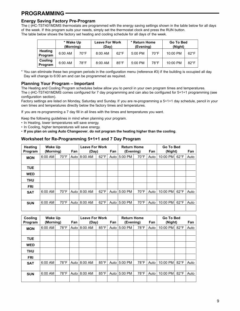
PROGRAMMINGEnergy Saving Factory Pre-ProgramThe (-)HC-TST401MDMS thermostats are programmed with the energy saving settings shown in the table below for all daysof the week. If this program suits your needs, simply set the thermostat clock and press the RUN button.The table below shows the factory set heating and cooling schedule for all days of the week.
* Wake Up Leave For Work * Return Home Go To Bed(Morning) (Day) (Evening) (Night)
HeatingProgram
CoolingProgram
6:00 AM 70°F 8:00 AM 62°F 5:00 PM 70°F 10:00 PM 62°F
6:00 AM 78°F 8:00 AM 85°F 5:00 PM 78°F 10:00 PM 82°F
* You can eliminate these two program periods in the configuration menu (reference #3) if the building is occupied all day.Day will change to 6:00 am and can be programmed as required.
Planning Your Program – ImportantThe Heating and Cooling Program schedules below allow you to pencil in your own program times and temperatures.The (-)HC-TST401MDMS comes configured for 7 day programming and can also be configured for 5+1+1 programming (seeconfiguration section).Factory settings are listed on Monday, Saturday and Sunday. If you are re-programming a 5+1+1 day schedule, pencil in yourown times and temperatures directly below the factory times and temperatures.
If you are re-programming a 7 day fill in all lines with the times and temperatures you want.
Keep the following guidelines in mind when planning your program.• In Heating, lower temperatures will save energy.• In Cooling, higher temperatures will save energy.• If you plan on using Auto Changeover, do not program the heating higher than the cooling.
Wake Up Leave For Work Return Home Go To Bed(Morning) Fan (Day) Fan (Evening) Fan (Night) Fan
6:00 AM 70°F Auto 8:00 AM 62°F Auto 5:00 PM 70°F Auto 10:00 PM 62°F Auto
6:00 AM 70°F Auto 8:00 AM 62°F Auto 5:00 PM 70°F Auto 10:00 PM 62°F Auto
HeatingProgram
MON
TUE
WED
THU
FRI
SAT
SUN 6:00 AM 70°F Auto 8:00 AM 62°F Auto 5:00 PM 70°F Auto 10:00 PM 62°F Auto
Worksheet for Re-Programming 5+1+1 and 7 Day Program
Wake Up Leave For Work Return Home Go To Bed(Morning) Fan (Day) Fan (Evening) Fan (Night) Fan
6:00 AM 78°F Auto 8:00 AM 85°F Auto 5:00 PM 78°F Auto 10:00 PM 82°F Auto
6:00 AM 78°F Auto 8:00 AM 85°F Auto 5:00 PM 78°F Auto 10:00 PM 82°F Auto
CoolingProgram
MON
TUE
WED
THU
FRI
SAT
SUN 6:00 AM 78°F Auto 8:00 AM 85°F Auto 5:00 PM 78°F Auto 10:00 PM 82°F Auto
10
PROGRAMMINGWired Remote Temperature SensingOne remote temperature sensor can be installed indoor oroutdoor and connected to the thermostat by a maximumcable length of 100 meters (300 ft). Three terminals, +, S & -are provided on the terminal block to connect to the White-Rodgers standard wired remote sensor. This sensor will beread by the thermostat only when 24VAC is present.When used as indoor sensor, the readings can be weightedwith the local sensor for specific program periods. User canenable or disable the remote sensor in the installer configu-ration mode and also the outdoor temperature can beselected to show on the display.
Once in the installer configuration mode, momentarily pressthe or touch key until display indicates Remote (at thetop left of the LCD) and OFF (default – in clock digits).Pressing or touch key will toggle the operation anddisplay from Remote OFF to Remote On.When Remote On is selected, press key for the display toindicate Remote In (for indoor remote).The or keys will toggle the operation and display fromRemote In to Outdoor Remote.When any remote is selected the temperature will display inthe clock digits for one second alternating with the currenttime for three seconds when in Run Schedule mode.Outdoor Remote will indicate at the top left of display foroutdoor remote reading.Only Remote will show at top left for indoor remote reading.(oF or oC will not indicate with remote temperature readings).
Sensing Range:Outdoor temperature range is -40 to 140oFIndoor temperature range is 32 oF to 99 oF
Weight of Remote Reading:When in view schedule mode the weight of the indoor remotesensor will be shown in the left actual temperature digitsdesignated as A2 (default for average weight), H4 (highweight) or L1 (low weight). The period (Morning, Day,Evening, Night) will also be shown to the right of the weightvalue in the actual temperature digits.When in view schedule mode, press and keys at thethe same time to sequence the indoor remote temperaturesensor weight from A2 to H4 to L1 and back to A2 for each ofthe program period times for each day. (The H4 weight istwice the weight of A2 and A2 is twice the weight of L1).
When Remote In is selected (with Remote selected to On),press key for the display to indicate the status of the localsensor LS On (default for thermostat local sensor opera-tional). The and keys will toggle the function anddisplay from LS (shown in actual temperature digits) and On(shown in clock digits) to LS OFF to designate the localsensor is disabled.
The local sensor may be disabled only if the indoor remotesensor is enabled and functional.If the indoor remote sensor is disabled or not functional, thelocal sensor will automatically enable and display in the runschedule mode.The actual temperature displayed in the run mode is themathematical weighted sum of the two temperature sensors– local and indoor remote.(Outdoor remote sensor is not used for this computation).If the remote sensor is absent or not enabled then the actualtemperature will be as measured by the local sensor.
Dual Fuel Temperature Set PointThe Thermostat can monitor outside temperature through anoutdoor remote sensor if installed and switch to gas heat andinhibit the compressor when in heat pump mode and outsidetemperature is below a user selectable value. This tempera-ture is called the dual fuel temperature set point. Thiseliminates the need for a fossil fuel kit.For this feature to be functional the following conditions areto be met:1. The thermostat must be in heat pump mode;2. The outdoor temperature sensor must be enabled and
operational.
Once in the installer configuration mode, step through themenu items until the display indicates dF (for dual fuel) in theactual temperature digits and 5 (default) in clock digits.Pressing the or touch keys will increment the dual fueltemperature setpoint from 5 to 50 (default unit is Fahrenheit).When the dual fuel temperature setpoint is any value above5oF this feature is enabled. If the actual outdoor temperatureis lower than this temperature setpoint the heat pump will beinhibited. If the balance point temperature setpoint is 5oF thefeature is disabled.When the dual fuel feature is enabled, the shut down of thecompressor stage(s) are delayed a programmable time witha default of 60 seconds after the auxiliary stage is energizedto minimize the time that the system may blow cooler air.Only when the dual fuel feature is enabled and the ispressed after the dual fuel feature dF is selected, the displaywill indicate Cd (for compressor delay) in actual temperaturedigits and 60 (default) in clock digits.Pressing the or touch keys will increment the compres-sor delay time to 99 seconds or decrement down to 0second.If the or touch keys are held depressed, the setpointwill increment or decrement one degree at the rate of onedegree every one half second for the first three seconds andthereafter at double the speed.
11
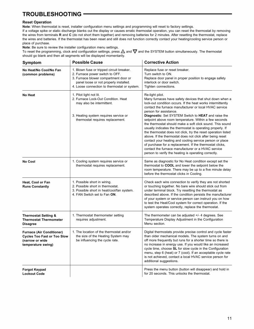
TROUBLESHOOTINGReset OperationNote: When thermostat is reset, installer configuration menu settings and programming will reset to factory settings.If a voltage spike or static discharge blanks out the display or causes erratic thermostat operation, you can reset the thermostat by removingthe wires from terminals R and C (do not short them together) and removing batteries for 2 minutes. After resetting the thermostat, replacethe wires and batteries. If the thermostat has been reset and still does not function correctly contact your heating/cooling service person orplace of purchase.Note: Be sure to review the installer configuration menu settings.To reset the programming, clock and configuration settings, press and and the SYSTEM button simultaneously. The thermostatshould go blank and then all segments will be displayed momentarily.
Symptom
No Heat/No Cool/No Fan(common problems)
No Heat
No Cool
Heat, Cool or FanRuns Constantly
Thermostat Setting &Thermostat ThermometerDisagree
Furnace (Air Conditioner)Cycles Too Fast or Too Slow(narrow or widetemperature swing)
Forgot KeypadLockout Code
Possible Cause
1. Blown fuse or tripped circuit breaker.2. Furnace power switch to OFF.3. Furnace blower compartment door or
panel loose or not properly installed.4. Loose connection to thermostat or system.
1. Pilot light not lit.2. Furnace Lock-Out Condition. Heat
may also be intermittent.
3. Heating system requires service orthermostat requires replacement.
1. Cooling system requires service orthermostat requires replacement.
1. Possible short in wiring.2. Possible short in thermostat.3. Possible short in heat/cool/fan system.4. FAN Switch set to Fan ON.
1. Thermostat thermometer settingrequires adjustment.
1. The location of the thermostat and/orthe size of the Heating System maybe influencing the cycle rate.
Corrective Action
Replace fuse or reset breaker.Turn switch to ON.Replace door panel in proper position to engage safetyinterlock or door switch.Tighten connections.
Re-light pilot.Many furnaces have safety devices that shut down when alock-out condition occurs. If the heat works intermittentlycontact the furnace manufacturer or local HVAC serviceperson for assistance.Diagnostic: Set SYSTEM Switch to HEAT and raise thesetpoint above room temperature. Within a few secondsthe thermostat should make a soft click sound. This soundusually indicates the thermostat is operating properly. Ifthe thermostat does not click, try the reset operation listedabove. If the thermostat does not click after being resetcontact your heating and cooling service person or placeof purchase for a replacement. If the thermostat clicks,contact the furnace manufacturer or a HVAC serviceperson to verify the heating is operating correctly.
Same as diagnostic for No Heat condition except set thethermostat to COOL and lower the setpoint below theroom temperature. There may be up to a five minute delaybefore the thermostat clicks in Cooling.
Check each wire connection to verify they are not shortedor touching together. No bare wire should stick out fromunder terminal block. Try resetting the thermostat asdescribed above. If the condition persists the manufacturerof your system or service person can instruct you on howto test the Heat/Cool system for correct operation. If thesystem operates correctly, replace the thermostat.
The thermometer can be adjusted +/- 4 degrees. SeeTemperature Display Adjustment in the ConfigurationMenu section.
Digital thermostats provide precise control and cycle fasterthan older mechanical models. The system turns on andoff more frequently but runs for a shorter time so there isno increase in energy use. If you would like an increasedcycle time, choose SL for slow cycle in the Configurationmenu, step 6 (heat) or 7 (cool). If an acceptable cycle rateis not achieved, contact a local HVAC service person foradditional suggestions.
Press the menu button (button will disappear) and hold infor 20 seconds. This unlocks the thermostat.

HOMEOWNER HELP LINE: 1-800-284-2925