savannah river site - salt waste processing facility independent
TRANSCRIPT

SALT WASTE PROCESSING FACILITY INDEPENDENT TECHNICAL REVIEW
November 22, 2006
Conducted by:
Harry Harmon, Team Lead Civil/Structural Sub Team Facility Safety Sub Team Engineering Sub Team Peter Lowry, Lead James Langsted, Lead George Krauter, Lead Robert Kennedy Chuck Negin Art Etchells Les Youd Jerry Evatt Oliver Block Loring Wyllie Richard Stark Tim Adams Tom Anderson Todd LaPointe Stephen Gosselin Carl Costantino Norman Moreau Patrick Corcoran John Christian Ken Cooper Kari McDaniel _____________________________ Harry D. Harmon ITR Team Leader
SPD-SWPF-217

SPD-SWPF-217: Salt Waste Processing Facility Independent Technical Review 11/22/2006
ACKNOWLEDGEMENT The ITR Team wishes to thank Shari Clifford of Pacific Northwest National Laboratory for her outstanding effort in compiling the draft report from 22 contributors, incorporating review comments, and completing the final report. She also provided significant logistical support to the ITR Sub Teams during our meetings. This report could not have been completed on schedule without her dedication and tireless efforts. The ITR Team also appreciates the technical editing and contract support provided by Tom Ivory, III of Concurrent Technologies Corporation. His efforts helped significantly in melding the writing styles of multiple contributors. The ITR Team could not have completed this task without the excellent support of the Parsons team. They provided internet access to the Enhanced Preliminary Design documentation, gave detailed presentations, and made their key staff members available for invaluable discussions. They also provided a meeting room with hard copies of the 35% design deliverables for the Team’s use when meeting in Aiken, South Carolina. Finally, the ITR Team acknowledges the excellent guidance and support received from our DOE technical points of contact: Hoyt Johnson (DOE-HQ) and Carl Lanigan (DOE-SR). They worked with the Team on finalizing our Charter, helped identify Team members, provided planning guidance when needed, and resolved any issues the Team encountered.
SPD-SWPF-217: Salt Waste Processing Facility Independent Technical Review 11/22/2006
TABLE OF CONTENTS TABLE OF CONTENTS ....................................................................................................... ii LIST OF FIGURES .................................................................................................................x LIST OF TABLES ...................................................................................................................x ACRONYMS.......................................................................................................................... xi EXECUTIVE SUMMARY ................................................................................................. xiii 1.0 INTRODUCTION........................................................................................................1
1.1 BACKGROUND ON THE SRS SALT PROCESSING PROGRAM ..............1 1.2 DESCRIPTION OF SALT WASTE PROCESSING FACILITY.....................1 1.3 THE INDEPENDENT REVIEW TEAM ..........................................................3 1.4 REPORT ORGANIZATION.............................................................................4 1.5 REFERENCES ..................................................................................................4
2.0 OVERALL PROJECT STATUS..............................................................................11
2.1 GENERAL PROJECT REQUIREMENTS .....................................................11 2.2 REFERENCES ................................................................................................11
3.0 CIVIL/STRUCTURAL DESIGN.............................................................................17
3.1 CENTRAL PROCESSING AREA (CPA) ......................................................17
3.1.1 CPA Civil/Structural Design................................................................17 3.1.1.1 Summary of response to LOI I.a.1.................................................17 3.1.1.2 Seismic analysis .............................................................................17
3.1.1.2.1 In-structure response spectra........................................17 3.1.1.2.2 Impedance functions ....................................................19 3.1.1.2.3 Vertical/Horizontal (V/H) ratio for input ground
motion vertical response spectra..................................21 3.1.1.2.4 Vertical floor amplification..........................................21 3.1.1.2.5 Benchmark finite element model element size
adequacy for determining out-of-plane moments and shears.....................................................................22
3.1.1.2.6 Validation of lumped mass and finite element models against each other ............................................22
3.1.1.2.7 Realistically model roof diaphragm.............................23 3.1.1.3 Design ............................................................................................23
3.1.1.3.1 Roofing not rigid diaphragm........................................23 3.1.1.3.2 Input from geotechnical on deflection from
settlement .....................................................................24
ii
SPD-SWPF-217: Salt Waste Processing Facility Independent Technical Review 11/22/2006
3.1.1.3.3 Typical reinforcing steel details...................................24 3.2 SUPPORT FACILITIES..................................................................................24
3.2.1 Support Facilities Civil/Structural Design ...........................................24 3.2.1.1 Summary of response to LOI I.b.1.................................................24 3.2.1.2 Use of tubes for vertical/diagonal bracing .....................................25 3.2.1.3 Utility connections through expansion joints ................................25 3.2.1.4 Waste transfer line (PC-2) .............................................................25
3.3 SUBSURFACE DESIGN ................................................................................26
3.3.1 Geotechnical Investigations .................................................................26 3.3.1.1 Summary of response to LOI I.c.1.................................................26 3.3.1.2 Review of geotechnical data ..........................................................27 3.3.1.3 Comparison of SWPF site soil profile with the SRS site-
wide profile ....................................................................................27 3.3.1.4 Identification of soft zones.............................................................27 3.3.1.5 Define subsidence model for soft zones that impact
foundation of structure...................................................................28 3.3.1.6 Seismically generated ground settlement.......................................28
3.4 RISK MANAGEMENT...................................................................................29
3.4.1 Structural Risks....................................................................................29 3.4.1.1 Summary of response to LOI I.d.1.................................................29 3.4.1.2 Moving forward without geotechnical data ...................................29 3.4.1.3 Increases to the in-structure response spectra................................29 3.4.2 Risks of Conversion from ISO-9001 to NQA-1 ..................................30 3.4.2.1 Summary of response to LOI I.d.2.................................................30
3.5 REFERENCES ................................................................................................30
4.0 FACILITY SAFETY .................................................................................................37
4.1 RADIATION PROTECTION .........................................................................37
4.1.1 Confinement.........................................................................................38 4.1.1.1 Summary of response to LOI II.a.1 ...............................................38 4.1.1.2 Consistent with PC-3 requirements ...............................................39 4.1.1.3 Filter loading uncertainty...............................................................39 4.1.1.4 Nuclear criticality...........................................................................39 4.1.1.5 Laboratory design ..........................................................................40 4.1.1.6 De-inventory and wash process .....................................................40 4.1.1.7 10 CFR 835 implementation..........................................................41
4.1.1.7.1 ALARA design ............................................................41 4.1.1.7.2 Physical design features...............................................42 4.1.1.7.3 Optimization methods used..........................................42 4.1.1.7.4 Avoid airborne radioactive material ............................43
iii
SPD-SWPF-217: Salt Waste Processing Facility Independent Technical Review 11/22/2006
4.1.2 Bulk Wall Shielding.............................................................................43 4.1.2.1 Summary of response to LOI II.a.2 ...............................................43 4.1.2.2 Bulk wall shielding analysis capability..........................................44 4.1.2.3 Bulk wall shielding analysis calculations ......................................44 4.1.2.4 Shielding design confirmation .......................................................46 4.1.2.5 Interaction with design...................................................................46 4.1.2.6 Shielding analysis quality assurance..............................................47 4.1.3 Radiation Scatter Through Penetrators, Pump, and Valve
Gallery Labyrinths ...............................................................................47 4.1.3.1 Summary of response to LOI II.a.3 ...............................................47 4.1.3.2 Labyrinth entrances........................................................................48 4.1.3.3 Penetrations....................................................................................48 4.1.3.4 Skyshine.........................................................................................48 4.1.4 Risk Management ................................................................................49 4.1.4.1 Summary of response to LOI II.a.4(i)............................................49 4.1.4.2 Summary of response to LOI II.a.4(ii)...........................................49
4.2 MATERIAL HANDLING...............................................................................51
4.2.1 Overhead Cranes/Hoists.......................................................................51 4.2.1.1 Summary of response to LOI II.b.1 ...............................................51 4.2.1.2 Operating envelop assessment .......................................................51
4.2.1.2.1 Bridge Crane – Operating Deck, Capacity: 20/7.5/1 Ton Hoists......................................................51
4.2.1.2.2 Bridge Crane – Hot Cell, Capacity: ½ Ton..................52 4.2.1.2.3 Bridge Crane – AFF, Capacity: 5 Ton .........................52
4.2.1.3 Equipment accessibility/maintenance assessment .........................52 4.2.1.3.1 Bridge Crane – Operating Deck, Capacity:
20/7.5/1 Ton Hoists......................................................52 4.2.1.3.2 Bridge Crane – Hot Cell, Capacity: ½ Ton..................53 4.2.1.2.3 Bridge Crane – AFF, Capacity: 5 Ton .........................53
4.2.2 Equipment Monorails/Carts .................................................................54 4.2.2.1 Summary of response to LOI II.b.2 ...............................................54 4.2.2.2 Operating envelop assessment – monorail hoist assemblies..........54
4.2.2.2.1 South ASP Pump and Valve Gallery, Central Process Area, Elevation: 100’-0”.................................54
4.2.2.2.2 North ASP Pump and Valve Gallery, Central Process Area, Elevation: 100’-0”.................................55
4.2.2.2.3 CSSX Pump and Valve Gallery, Central Process Area, Elevation 100’-0” ...............................................55
4.2.2.2.4 Waste Transfer Access Room, Central Process Area, Elevation 111’-0” ...............................................55
4.2.2.2.5 Contactor Operating Deck, Central Process Area, Elevation 124’-0” ...............................................55
4.2.2.2.6 CSSX Tank Cell Operating Deck, Central Process Area, Elevation 124’-0”..................................55
iv

SPD-SWPF-217: Salt Waste Processing Facility Independent Technical Review 11/22/2006
4.2.2.2.7 CSSX Contactor Drop Area, Central Process Area, Elevation 116’-0” ...............................................56
4.2.2.2.8 Truck Bay and Dock, Eastern Facility Support Area, Elevation 100’-0” ...............................................56
4.2.2.2.9 Tanks – Cold Chemical Area, Elevation 100’-0” ........56 4.2.2.3 Operating envelop assessment – transport carts ............................56 4.2.2.4 Equipment accessibility/maintenance assessment .........................56 4.2.3 Laboratory Conveyor/Gloveboxes/Radiohoods...................................57 4.2.3.1 Summary of response to LOI II.b.3 ...............................................57 4.2.3.2 Operating envelop assessment .......................................................57
4.2.3.2.1 Conveyors ....................................................................57 4.2.3.2.2 Gloveboxes/Radiohoods ..............................................58
4.2.3.3 Equipment accessibility/maintenance assessment .........................58 4.2.3.4 Sample-handling/disposal assessment ...........................................58 4.2.4 Risk Management ................................................................................59 4.2.4.1 Material Handling Risks ................................................................59
4.2.4.1.1 Summary of response to LOI II.b.4(i) .........................59 4.2.4.1.2 ALARA – handling/packaging of failed
equipment.....................................................................59 4.2.4.2 Risks of Conversion from ISO-9001 to NQA-1 ............................60
4.2.4.2.1 Summary of response to LOI II.b.4(ii) ........................60 4.3 INTEGRATED SAFETY MANAGEMENT (ISM) .......................................62
4.3.1 ISM Principles for Protection of Workers, Public and Environment.........................................................................................62
4.3.1.1 Summary of response to LOI II.c.1 ...............................................62 4.3.1.2 ISM principles and the PDSA........................................................62 4.3.1.3 Business, budget and contracts ......................................................63
4.3.1.3.1 DOE and contractor procedures and missions .............63 4.3.1.3.2 DOE and contractor budgets and resources .................64 4.3.1.3.3 Contractor scope and resource allocation
competencies................................................................66 4.3.1.4 ISMS and Management of the Project ...........................................66
4.3.1.4.1 ISMS description adequacy .........................................66 4.3.1.4.2 Contractor roles and responsibility ..............................67
4.3.2 Facility Hazards and Risk Analysis in PDSA......................................68 4.3.2.1 Summary of response to LOI II.c.2 ...............................................68
4.4 QUALITY ASSURANCE...............................................................................70
4.4.1 ISO-9001 QA Assessments and Corrective Action Results ................70 4.4.1.1 Summary of response to LOI II.d.1 ...............................................70 4.4.2 Impacts of NQA-1 Conversion after Preliminary Design....................70 4.4.2.1 Summary of response to LOI II.d.2 ...............................................70 4.4.3 NQA-1 Impacts on Completed Design ................................................71 4.4.3.1 Summary of response to LOI II.d.3 ...............................................71 4.4.3.2 Computer software QA concerns...................................................71
v

SPD-SWPF-217: Salt Waste Processing Facility Independent Technical Review 11/22/2006
4.5 REFERENCES ................................................................................................72
5.0 ENGINEERING.........................................................................................................78
5.1 PROCESS DESIGN.........................................................................................78
5.1.1 Maturity of Process Design..................................................................78 5.1.1.1 Summary of response to LOI III.a.1 ..............................................78 5.1.1.2 Review of applicable process design criteria.................................78
5.1.1.2.1 Standard/Requirements Identification Document........79 5.1.1.2.2 Feed Strategy and Product and Secondary Waste
Specification ................................................................80 5.1.1.2.3 Functional Specification ..............................................80 5.1.1.2.4 SWPF Process Basis of Design....................................80 5.1.1.2.5 Operations Requirements Document ...........................81 5.1.1.2.6 Facility Project Design Database .................................82
5.1.1.3 Evaluation of the implementing documents ..................................83 5.1.1.3.1 Process Flow Diagrams and Piping and
Instrumentation Diagrams............................................83 5.1.1.3.2 General Arrangements .................................................84 5.1.1.3.3 Operations Assessment and Tank Utilization
Models..........................................................................85 5.1.1.3.4 Design Process Description .........................................85 5.1.1.3.5 Nuclear Criticality Safety Evaluation: SWPF..............85 5.1.1.3.6 Recommended SWPF Waste Compliance Plan
for Transfers to the Defense Waste Processing Facility and Saltstone Production Facility ...................86
5.1.1.4 Particulate solids as a source of problems .....................................86 5.1.1.5 Input solid properties .....................................................................86 5.1.1.6 Slurry handling...............................................................................87 5.1.1.7 Flushing..........................................................................................88 5.1.1.8 Pumps.............................................................................................88 5.1.1.9 Air Pulse Agitation Test Plan ........................................................89 5.1.1.10 APA Mixer Sizing Program...........................................................90 5.1.1.11 Centrifugal Contactors ...................................................................90 5.1.1.12 Organics – formation and filtration of organic solids....................91 5.1.1.13 Coalescers ......................................................................................91 5.1.2 CSSX Test Plans and Results ..............................................................92 5.1.2.1 Summary of response to LOI III.a.2 ..............................................92 5.1.3 MST/Filtration Test Plans and Results ................................................92 5.1.3.1 Summary of response to LOI III.a.3 ..............................................92 5.1.3.2 APA Test Plans and results............................................................92
5.2 MECHANICAL EQUIPMENT/PIPING/TANK DESIGN.............................99
5.2.1 Maturity of Equipment, Piping, and Tank Design...............................99 5.2.1.1 Summary of response to LOI III.b.1(i) ..........................................99
vi

SPD-SWPF-217: Salt Waste Processing Facility Independent Technical Review 11/22/2006
5.2.1.2 Mechanical equipment .................................................................100 5.2.1.2.1 Contactors ..................................................................101 5.2.1.2.2 Cross-flow heat exchangers .......................................101 5.2.1.2.3 Valves – all types .......................................................102
5.2.1.3 ASME pressure vessel and API 650 tanks...................................102 5.2.1.3.1 APA issues .................................................................102 5.2.1.3.2 APA 650 storage tanks...............................................103
5.2.1.4 Process piping ..............................................................................103 5.2.1.5 Non-process piping ......................................................................104 5.2.1.6 Fire protection piping...................................................................104 5.2.2 Adequacy of PC-3 and PC-1 Equipment, Piping, and Tank
Design ................................................................................................104 5.2.2.1 Summary of response to LOI III.b.1(ii) .......................................104 5.2.2.2 Mechanical equipment .................................................................105
5.2.2.2.1 Pumps (PC-1 and -3)..................................................105 5.2.2.2.2 Specifications.............................................................105 5.2.2.2.3 Dark cell and PC-3 equipment...................................106 5.2.2.2.4 Valves, all types .........................................................107
5.2.2.3 ASME pressure vessel and API 650 tanks...................................107 5.2.2.3.1 PC-3 vessels ...............................................................108 5.2.2.3.2 PC-1 and -2 vessels....................................................108 5.2.2.3.3 API 650 tanks.............................................................108
5.2.2.4 Process piping ..............................................................................109 5.2.2.4.1 PC-1, -2, -3 acceptance criteria..................................109 5.2.2.4.2 Pipe supports..............................................................111 5.2.2.4.3 Dark cell piping..........................................................111
5.2.2.5 Non-process piping ......................................................................112 5.2.2.6 Fire protection systems ................................................................112 5.2.3 Review of corrosion allowances mechanical equipment,
piping and vessels ........................................................................113 5.2.3.1 Process and chemical storage tanks .............................................114
5.2.3.1.1 Oxalic acid corrosion ..............................................114 5.2.3.1.2 Caustic corrosion ....................................................115 5.2.3.1.3 Stress corrosion cracking ........................................115 5.2.3.1.4 Pitting and crevice corrosion ..................................116 5.2.3.1.5 Thermal fatigue.......................................................117 5.2.3.1.6 Erosion in TK-101 and TK-102..............................117
5.2.3.2 Process filtration piping ...............................................................117 5.2.3.2.1 Erosion of filtration piping between TK-102
and TK-222 .............................................................117 5.2.3.2.2 Caustic and oxalic corrosion...................................118 5.2.3.2.3 Erosion-corrosion....................................................118
5.2.3.3 Buried piping ...............................................................................118 5.2.4 Seismic Input Concerns ...............................................................118 5.2.5 Accident Analysis Concerns ........................................................119
vii

SPD-SWPF-217: Salt Waste Processing Facility Independent Technical Review 11/22/2006
5.3 HEATING, VENTILATION, AND AIR CONDITIONING (HVAC) .........125 5.3.1 Maturity of HVAC (Building Ventilation, Process Vessel Vent
System, and Process Mixer Vent System) Design.............................125 5.3.1.1 Summary of response to LOI III.b.2............................................125 5.3.1.2 Confinement design .....................................................................125 5.3.1.3 HVAC air flow and control drawings..........................................126 5.3.1.4 HVAC layout drawings................................................................126 5.3.1.5 HVAC supports drawings and calculations .................................126 5.3.1.6 HAVC calculations ......................................................................127 5.3.1.7 Acceptance test requirements/functional test requirements.........127 5.3.1.8 HVAC specifications ...................................................................127 5.3.2 Performance Category Design Designations .....................................128 5.3.2.1 Summary of LOI III.b1(ii) – Adequacy of PC-3 and PC-1
HVAC design...............................................................................128 5.4 ELECTRICAL DESIGN ...............................................................................130
5.4.1 Maturity of Electrical Design.............................................................130 5.4.1.1 Summary of response to LOI III.c.1 ............................................130 5.4.1.2 Electrical power system feeds......................................................130 5.4.1.3 Evaluation of the electrical power system ...................................131 5.4.1.4 Calculations to support issued design..........................................134 5.4.1.5 Underground activities.................................................................134 5.4.1.6 Design criteria..............................................................................136 5.4.1.7 Lighting calculations....................................................................136 5.4.2 Cable Tray Layouts............................................................................137 5.4.2.1 Summary of response to LOI III.c.2 ............................................137 5.4.2.2 Evaluation of cable tray systems..................................................137 5.4.2.3 Cable and raceway scheduling.....................................................137
5.5 INSTRUMENTATION AND CONTROL (I&C) .........................................142
5.5.1 Maturity of I&C Design.....................................................................142 5.5.1.1 Summary of response to LOI III.d.1............................................142 5.5.1.2 System architecture......................................................................142 5.5.1.3 Design technology .......................................................................142 5.5.1.4 Equipment ....................................................................................142 5.5.1.5 Software quality assurance ..........................................................143 5.5.1.6 Design process .............................................................................143
5.5.1.6.1 Design procedures......................................................143 5.5.1.6.2 Safety significant instrumented systems....................143 5.5.1.6.3 Functional classification ............................................144
5.5.1.7 Control philosophy.......................................................................144 5.5.1.8 Plant simulator .............................................................................145 5.5.1.9 Human factors engineering ..........................................................145 5.5.1.10 Seismic switch .............................................................................146 5.5.2 Cable Tray Layouts............................................................................146 5.5.2.1 Summary of response to LOI III.d.2............................................146
viii
SPD-SWPF-217: Salt Waste Processing Facility Independent Technical Review 11/22/2006
5.5.3 Valve Procurement.............................................................................146 5.5.4 Impact of NQA-1 ...............................................................................147 5.5.5 Operations Participation in Design ....................................................147
5.6 LIMITED CONSTRUCTION .......................................................................151
5.6.1 Maturity of Limited Construction CD-3 Design................................151 5.6.1.1 Summary of response to LOI III.d.1............................................151 5.6.2 Scope for CD-3A ...............................................................................151 5.6.2.1 Summary of response to LOI III.d.2............................................151
5.7 OPERATIONS, MAINTENANCE, AND DECONTAMINATION
AND DECOMMISSIONING (D&D) ...........................................................151 5.7.1 Operations, Maintenance, and D&D Design Futures ........................151 5.7.1.1 Summary of response to LOI III.f.1.............................................151 5.7.1.2 Operations and Maintenance........................................................153
5.7.1.2.1 Operations requirements document ...........................153 5.7.1.2.2 Commissioning strategy.............................................154
5.7.1.3 Decontamination and Decommissioning .....................................154 5.7.1.3.1 Review approach........................................................154
5.8 RISK MANAGEMENT.................................................................................161 5.8.1 Engineering Risks ..............................................................................161 5.8.1.1 Summary of response to LOI III.g.1............................................161 5.8.1.2 Valve procurement risk................................................................161 5.8.1.3 Undissolved solids .......................................................................161 5.8.1.4 Vessel/tank design .......................................................................161 5.8.2 Risks of Conversion from ISO-9001 to NQA-1 ................................162 5.8.2.1 Summary of response to LOI III.g.2............................................162
5.9 REFERENCES ..............................................................................................162
6.0 CONCLUSIONS AND RECOMMENDATIONS.................................................168
ATTACHMENT 1: SWPF INDEPENDENT REVIEW TEAM CHARTER ATTACHMENT 2: SWPF INDEPENDENT REVIEW TEAM RESUMES ATTACHMENT 3: LIST OF CATEGORIZED FINDINGS AND
RECOMMENDATIONS
ix

SPD-SWPF-217: Salt Waste Processing Facility Independent Technical Review 11/22/2006
LIST OF FIGURES Figure 1-1 SWPF Process Flow Sheet....................................................................................6 Figure 4-1 Dose Rate with Concrete Shielding for 86 Ci/gal Infinite Source......................45 Figure 5-1 Basic Hierarchy of Design Criteria and Specifications ....................................120 Figure 5-2 Suggested Sample Format and Detail for Criteria Specification in
Procurement and Qualification Specifications..................................................121
LIST OF TABLES Table ES-1 Summary of Responses to Lines of Inquiry...................................................... xvi Table ES-2 SWPF ITR Technical Issues ............................................................................. xix Table 1-1 Independent Technical Review Expertise.............................................................7 Table 2-1 General Requirements.........................................................................................12 Table 3-1 Civil/Structural Design .......................................................................................31 Table 4-1 Facility Safety - Radiation Protection.................................................................50 Table 4-2 Facility Safety - Material Handling ....................................................................61 Table 4-3 Facility Safety - Integrated Safety Management ................................................69 Table 5-1 Engineering - Process Design .............................................................................94 Table 5-2 Engineering - Piping .........................................................................................122 Table 5-3 Engineering - HVAC ........................................................................................129 Table 5-4 Engineering - Electrical ....................................................................................139 Table 5-5 Engineering - Instrumentation and Control ......................................................148 Table 5-6 Engineering - Operation, Maintenance, and D&D ...........................................152 Table 5-7 Review of the Design for Decommissioning ....................................................157 Table 6-1 Summary of Responses to Lines of Inquiry......................................................169 Table 6-2 SWPF ITR Technical Issues .............................................................................179
x
SPD-SWPF-217: Salt Waste Processing Facility Independent Technical Review 11/22/2006
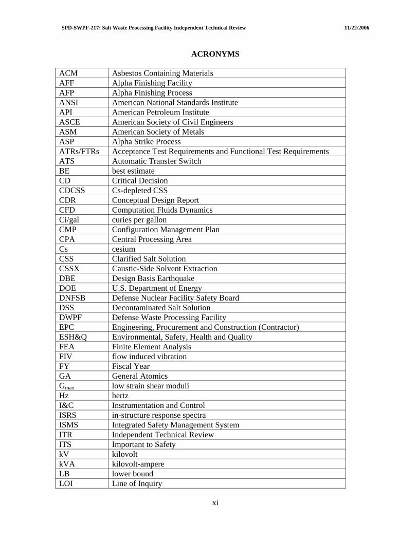
ACRONYMS
ACM Asbestos Containing Materials AFF Alpha Finishing Facility AFP Alpha Finishing Process ANSI American National Standards Institute API American Petroleum Institute ASCE American Society of Civil Engineers ASM American Society of Metals ASP Alpha Strike Process ATRs/FTRs Acceptance Test Requirements and Functional Test Requirements ATS Automatic Transfer Switch BE best estimate CD Critical Decision CDCSS Cs-depleted CSS CDR Conceptual Design Report CFD Computation Fluids Dynamics Ci/gal curies per gallon CMP Configuration Management Plan CPA Central Processing Area Cs cesium CSS Clarified Salt Solution CSSX Caustic-Side Solvent Extraction DBE Design Basis Earthquake DOE U.S. Department of Energy DNFSB Defense Nuclear Facility Safety Board DSS Decontaminated Salt Solution DWPF Defense Waste Processing Facility EPC Engineering, Procurement and Construction (Contractor) ESH&Q Environmental, Safety, Health and Quality FEA Finite Element Analysis FIV flow induced vibration FY Fiscal Year GA General Atomics Gmax low strain shear moduli Hz hertz I&C Instrumentation and Control ISRS in-structure response spectra ISMS Integrated Safety Management System ITR Independent Technical Review ITS Important to Safety kV kilovolt kVA kilovolt-ampere LB lower bound LOI Line of Inquiry
xi

SPD-SWPF-217: Salt Waste Processing Facility Independent Technical Review 11/22/2006
MeV Million electron volts Mgal Million of gallons MST monosodium titanate Na+ sodium ion NCR Nonconformance Reports NDE Non-destructive examination P2D Pollution Prevention in Design PC Performance Category PCB polychlorinated biphenyl psig pounds per square inch gauge RAMI Reliability, Availability, Maintainability, and Inspectability RT Radiographic Testing SC Safety Class SCC Stress Corrosion Cracking SCG Standby Diesel Generator SIL Safety Integrity Level SPF Saltstone Production Facility Sr strontium SRS Savannah River Site SS Safety Significant SSIS Safety Significant Instrumented Systems SWPF Salt Waste Processing Facility UB Upper Bound UT Ultrasonic Testing V&V verify and validate or verification and validation V/H Vertical/Horizontal VP,DBE seismic strain compression wave velocity VS,DBE seismic strain shear wave velocity VS, Low low strain shear wave WAC Waste Acceptance Criteria
xii
SPD-SWPF-217: Salt Waste Processing Facility Independent Technical Review 11/22/2006
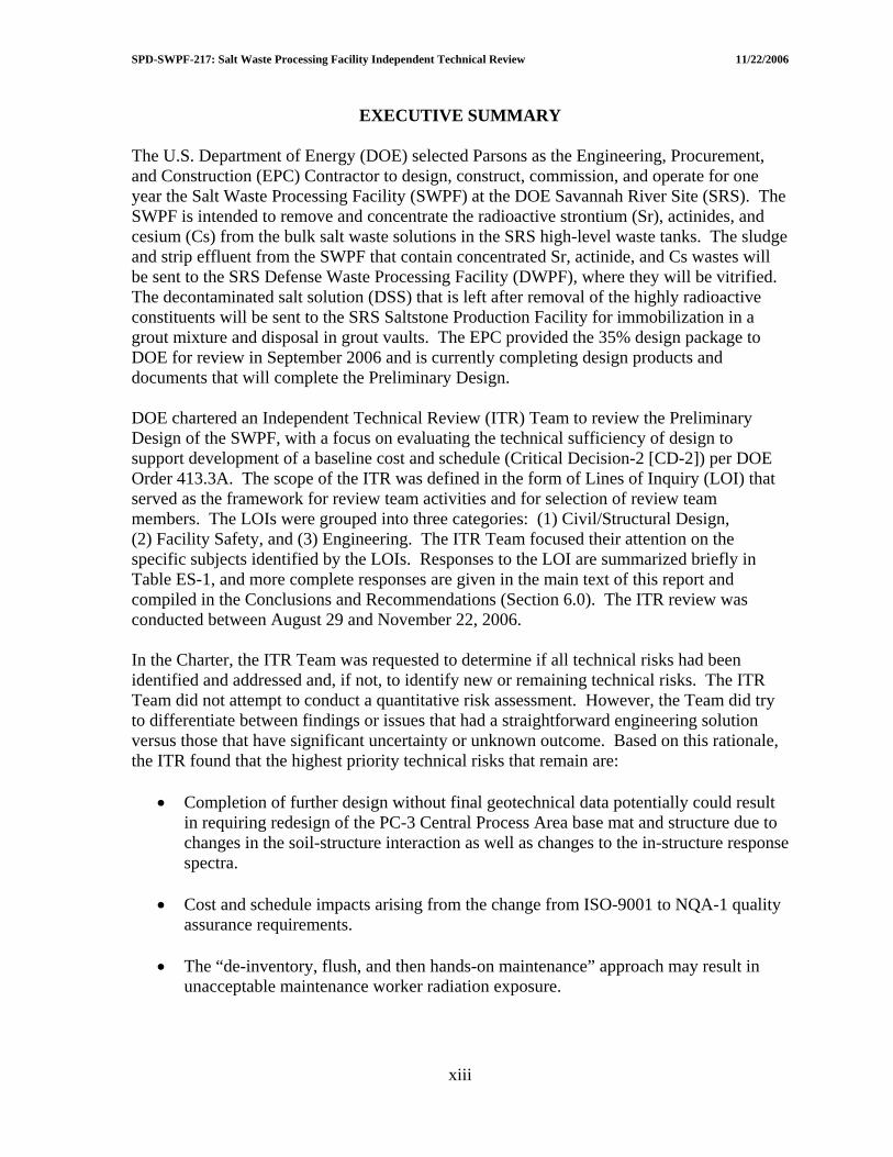
EXECUTIVE SUMMARY The U.S. Department of Energy (DOE) selected Parsons as the Engineering, Procurement, and Construction (EPC) Contractor to design, construct, commission, and operate for one year the Salt Waste Processing Facility (SWPF) at the DOE Savannah River Site (SRS). The SWPF is intended to remove and concentrate the radioactive strontium (Sr), actinides, and cesium (Cs) from the bulk salt waste solutions in the SRS high-level waste tanks. The sludge and strip effluent from the SWPF that contain concentrated Sr, actinide, and Cs wastes will be sent to the SRS Defense Waste Processing Facility (DWPF), where they will be vitrified. The decontaminated salt solution (DSS) that is left after removal of the highly radioactive constituents will be sent to the SRS Saltstone Production Facility for immobilization in a grout mixture and disposal in grout vaults. The EPC provided the 35% design package to DOE for review in September 2006 and is currently completing design products and documents that will complete the Preliminary Design. DOE chartered an Independent Technical Review (ITR) Team to review the Preliminary Design of the SWPF, with a focus on evaluating the technical sufficiency of design to support development of a baseline cost and schedule (Critical Decision-2 [CD-2]) per DOE Order 413.3A. The scope of the ITR was defined in the form of Lines of Inquiry (LOI) that served as the framework for review team activities and for selection of review team members. The LOIs were grouped into three categories: (1) Civil/Structural Design, (2) Facility Safety, and (3) Engineering. The ITR Team focused their attention on the specific subjects identified by the LOIs. Responses to the LOI are summarized briefly in Table ES-1, and more complete responses are given in the main text of this report and compiled in the Conclusions and Recommendations (Section 6.0). The ITR review was conducted between August 29 and November 22, 2006. In the Charter, the ITR Team was requested to determine if all technical risks had been identified and addressed and, if not, to identify new or remaining technical risks. The ITR Team did not attempt to conduct a quantitative risk assessment. However, the Team did try to differentiate between findings or issues that had a straightforward engineering solution versus those that have significant uncertainty or unknown outcome. Based on this rationale, the ITR found that the highest priority technical risks that remain are:
• Completion of further design without final geotechnical data potentially could result in requiring redesign of the PC-3 Central Process Area base mat and structure due to changes in the soil-structure interaction as well as changes to the in-structure response spectra.
• Cost and schedule impacts arising from the change from ISO-9001 to NQA-1 quality
assurance requirements.
• The “de-inventory, flush, and then hands-on maintenance” approach may result in unacceptable maintenance worker radiation exposure.
xiii
SPD-SWPF-217: Salt Waste Processing Facility Independent Technical Review 11/22/2006
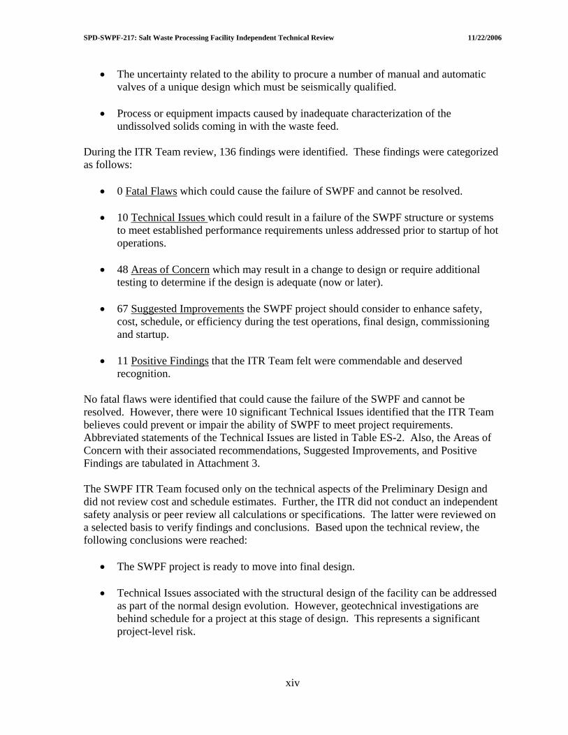
• The uncertainty related to the ability to procure a number of manual and automatic valves of a unique design which must be seismically qualified.
• Process or equipment impacts caused by inadequate characterization of the
undissolved solids coming in with the waste feed. During the ITR Team review, 136 findings were identified. These findings were categorized as follows:
• 0 Fatal Flaws which could cause the failure of SWPF and cannot be resolved.
• 10 Technical Issues which could result in a failure of the SWPF structure or systems to meet established performance requirements unless addressed prior to startup of hot operations.
• 48 Areas of Concern which may result in a change to design or require additional
testing to determine if the design is adequate (now or later).
• 67 Suggested Improvements the SWPF project should consider to enhance safety, cost, schedule, or efficiency during the test operations, final design, commissioning and startup.
• 11 Positive Findings that the ITR Team felt were commendable and deserved
recognition. No fatal flaws were identified that could cause the failure of the SWPF and cannot be resolved. However, there were 10 significant Technical Issues identified that the ITR Team believes could prevent or impair the ability of SWPF to meet project requirements. Abbreviated statements of the Technical Issues are listed in Table ES-2. Also, the Areas of Concern with their associated recommendations, Suggested Improvements, and Positive Findings are tabulated in Attachment 3. The SWPF ITR Team focused only on the technical aspects of the Preliminary Design and did not review cost and schedule estimates. Further, the ITR did not conduct an independent safety analysis or peer review all calculations or specifications. The latter were reviewed on a selected basis to verify findings and conclusions. Based upon the technical review, the following conclusions were reached:
• The SWPF project is ready to move into final design.
• Technical Issues associated with the structural design of the facility can be addressed as part of the normal design evolution. However, geotechnical investigations are behind schedule for a project at this stage of design. This represents a significant project-level risk.
xiv

SPD-SWPF-217: Salt Waste Processing Facility Independent Technical Review 11/22/2006
• The primary processes (monosodium titanate sorption of actinides and strontium and cesium removal by Caustic Side Solvent Extraction) are technically sound, and the planned large-scale equipment tests will provide very useful data to confirm and/or improve upon the current design.
• The SWPF project has experienced several major changes in requirements since
conceptual design: PC-2 to PC-3, conversion from ISO-9001 to NQA-1, and DOE Interim Safety Guidance. The full impacts of these changes are still being assessed by the EPC and DOE.
• The unique operations and maintenance approach (dark cells with no expected
maintenance and other equipment maintenance by flushing and hands-on maintenance) will require rigorous design and quality assurance measures to support procurement and construction.
• The current design is dependent on procuring a seismically qualified valve that
isolates the process system in the event of an earthquake. The design of this valve is very different from other valves which have been seismically qualified for nuclear applications. If this valve cannot be purchased, a significant change to the current design will be required. An immediate effort should be made to determine if the valve can be procured.
• The level of maturity of several areas of design, notably I&C and electrical, is in
excess of that expected at the 35% design point.
• A number of common design issues and process concerns exist between SWPF and the Hanford Waste Treatment Project. A technical exchange between DOE’s major waste treatment projects should be considered to address common concerns and share lessons learned.
In summary, the ITR Team concluded that the SWPF project is ready to move into final design. Response to the Technical Issues the ITR identified will be required to ensure successful SWPF system performance. Further, response to the Areas of Concern and Suggested Improvements will enhance the robustness of the design and the operability of the facility. Finally, the ITR recommends future focused independent reviews on critical ongoing activities including geotechnical studies, air pulse agitator testing, large-scale cross-flow filtration, and full-scale Caustic Side Solvent Extraction centrifugal contactor testing.
xv
SPD-SWPF-217: Salt Waste Processing Facility Independent Technical Review 11/22/2006
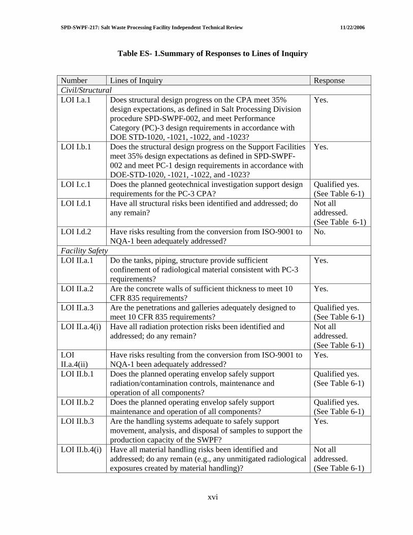
Table ES- 1.Summary of Responses to Lines of Inquiry
Number Lines of Inquiry Response Civil/Structural LOI I.a.1 Does structural design progress on the CPA meet 35%
design expectations, as defined in Salt Processing Division procedure SPD-SWPF-002, and meet Performance Category (PC)-3 design requirements in accordance with DOE STD-1020, -1021, -1022, and -1023?
Yes.
LOI I.b.1 Does the structural design progress on the Support Facilities meet 35% design expectations as defined in SPD-SWPF-002 and meet PC-1 design requirements in accordance with DOE-STD-1020, -1021, -1022, and -1023?
Yes.
LOI I.c.1 Does the planned geotechnical investigation support design requirements for the PC-3 CPA?
Qualified yes. (See Table 6-1)
LOI I.d.1 Have all structural risks been identified and addressed; do any remain?
Not all addressed. (See Table 6-1)
LOI I.d.2 Have risks resulting from the conversion from ISO-9001 to NQA-1 been adequately addressed?
No.
Facility Safety LOI II.a.1 Do the tanks, piping, structure provide sufficient
confinement of radiological material consistent with PC-3 requirements?
Yes.
LOI II.a.2 Are the concrete walls of sufficient thickness to meet 10 CFR 835 requirements?
Yes.
LOI II.a.3 Are the penetrations and galleries adequately designed to meet 10 CFR 835 requirements?
Qualified yes. (See Table 6-1)
LOI II.a.4(i) Have all radiation protection risks been identified and addressed; do any remain?
Not all addressed. (See Table 6-1)
LOI II.a.4(ii)
Have risks resulting from the conversion from ISO-9001 to NQA-1 been adequately addressed?
Yes.
LOI II.b.1 Does the planned operating envelop safely support radiation/contamination controls, maintenance and operation of all components?
Qualified yes. (See Table 6-1)
LOI II.b.2 Does the planned operating envelop safely support maintenance and operation of all components?
Qualified yes. (See Table 6-1)
LOI II.b.3 Are the handling systems adequate to safely support movement, analysis, and disposal of samples to support the production capacity of the SWPF?
Yes.
LOI II.b.4(i) Have all material handling risks been identified and addressed; do any remain (e.g., any unmitigated radiological exposures created by material handling)?
Not all addressed. (See Table 6-1)
xvi

SPD-SWPF-217: Salt Waste Processing Facility Independent Technical Review 11/22/2006
Number Lines of Inquiry Response LOI II.b.4(ii)
Have risks resulting from the conversion from ISO-9001 to NQA-1 been adequately addressed?
Yes.
LOI II.c.1 Has the design of the SWPF followed ISM principals for the protection of the workers, public and environment?
Yes.
LOI II.c.2 Have the appropriate facility hazards been identified and were the risks from these hazards properly analyzed in the Preliminary Documented Safety Analysis (PDSA)?
Yes.
LOI II.d.1 Were QA assessments of ISO-9001 implementation effective in identifying issues in preliminary design and have corrective actions been taken?
Yes.
LOI II.d.2 Have the impacts of conversion to NQA-1 after preliminary design been assessed adequately?
No.
LOI II.d.3 Do the impacts of NQA-1 challenge any of the completed design?
Qualified no. (See Table 6-1)
Engineering LOI III.a.1 Does the maturity of the process design support 35%
completion status, as defined in Salt Processing Division procedure SPD-SWPF-002?
Yes.
LOI III.a.2 Do the Caustic Side Solvent Extraction (CSSX) test program plans and results provide sufficient assurance that engineering development for this technology has reached the necessary technical maturity required for final design?
Qualified yes. (See Table 6-1)
LOI III.a.3 Do the Monosodium Titanate (MST)/Filtration test program plans and results provide sufficient assurance that engineering development for this technology has reached the necessary technical maturity required for final design?
Yes.
LOI III.b.1(i)
Does the maturity of the equipment/piping/tank/HVAC design support 35% completion status, as defined in Salt Processing Division procedure SPD-SWPF-002?
Yes.
LOI III.b.1(ii)
Are the design designations for the PC-3 and PC-1 piping, vessels, and equipment adequate?
Yes.
LOI III.b.2 Does the maturity of the HVAC (Building ventilation, Process Vessel Vent System [PVVS], and Process Mixer Vent System [PMVS]) design support 35% completion status, as defined in Salt Processing Division procedure SPD-SWPF-002?
Yes.
LOI III.b.1(ii)
Adequacy of PC-3 and PC-1 HVAC design? Yes.
LOI III.c.1 Although the electrical design generally trails the other disciplines, is the electrical portion of the design sufficiently mature to define all major components (e.g., transformers) as well as sufficient electrical capacity to provide for future expansion?
Yes.
LOI III.c.2 Are basic cable tray layouts sufficiently developed to provide an accurate construction cost estimate?
Yes.
xvii

SPD-SWPF-217: Salt Waste Processing Facility Independent Technical Review 11/22/2006
Number Lines of Inquiry Response LOI III.d.1 Although the I&C design generally trails the other
disciplines, is the I&C design sufficiently mature to define all major components (e.g., number of Input/Output) as well as sufficient surplus capacity to provide for future expansion?
Yes.
LOI III.d.2 Are basic cable tray layouts sufficiently developed to provide an accurate construction cost estimate?
Yes.
LOI III.e.1 Does the scope identified for the Limited Construction has a completed design and a CD-3 level construction cost estimate?
Insufficient information to review.
LOI III.e.2 Does the scope identified for CD-3A provide a reasonable optimization between schedule improvement and risk reduction?
Insufficient information to review.
LOI III.f.1 Does the design include features which will adequately support future operation, maintenance and D&D of the facility?
Yes.
LOI III.g.1 Have all engineering risks been identified and addressed; do any remain?
Not all addressed. (See Table 6-1)
LOI III.g.2 Have risks resulting from the conversion from ISO-9001 to NQA-1 been adequately addressed?
No.
xviii
SPD-SWPF-217: Salt Waste Processing Facility Independent Technical Review 11/22/2006
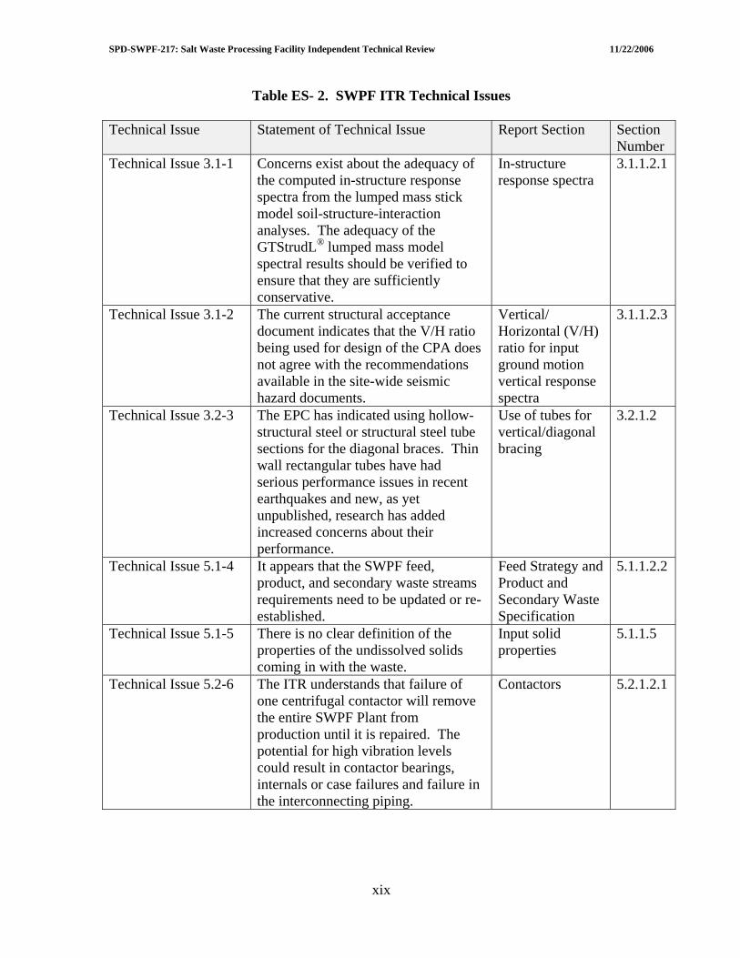
Table ES- 2. SWPF ITR Technical Issues Technical Issue Statement of Technical Issue Report Section Section
Number Technical Issue 3.1-1 Concerns exist about the adequacy of
the computed in-structure response spectra from the lumped mass stick model soil-structure-interaction analyses. The adequacy of the GTStrudL® lumped mass model spectral results should be verified to ensure that they are sufficiently conservative.
In-structure response spectra
3.1.1.2.1
Technical Issue 3.1-2 The current structural acceptance document indicates that the V/H ratio being used for design of the CPA does not agree with the recommendations available in the site-wide seismic hazard documents.
Vertical/ Horizontal (V/H) ratio for input ground motion vertical response spectra
3.1.1.2.3
Technical Issue 3.2-3 The EPC has indicated using hollow-structural steel or structural steel tube sections for the diagonal braces. Thin wall rectangular tubes have had serious performance issues in recent earthquakes and new, as yet unpublished, research has added increased concerns about their performance.
Use of tubes for vertical/diagonal bracing
3.2.1.2
Technical Issue 5.1-4 It appears that the SWPF feed, product, and secondary waste streams requirements need to be updated or re-established.
Feed Strategy and Product and Secondary Waste Specification
5.1.1.2.2
Technical Issue 5.1-5 There is no clear definition of the properties of the undissolved solids coming in with the waste.
Input solid properties
5.1.1.5
Technical Issue 5.2-6 The ITR understands that failure of one centrifugal contactor will remove the entire SWPF Plant from production until it is repaired. The potential for high vibration levels could result in contactor bearings, internals or case failures and failure in the interconnecting piping.
Contactors 5.2.1.2.1
xix
SPD-SWPF-217: Salt Waste Processing Facility Independent Technical Review 11/22/2006
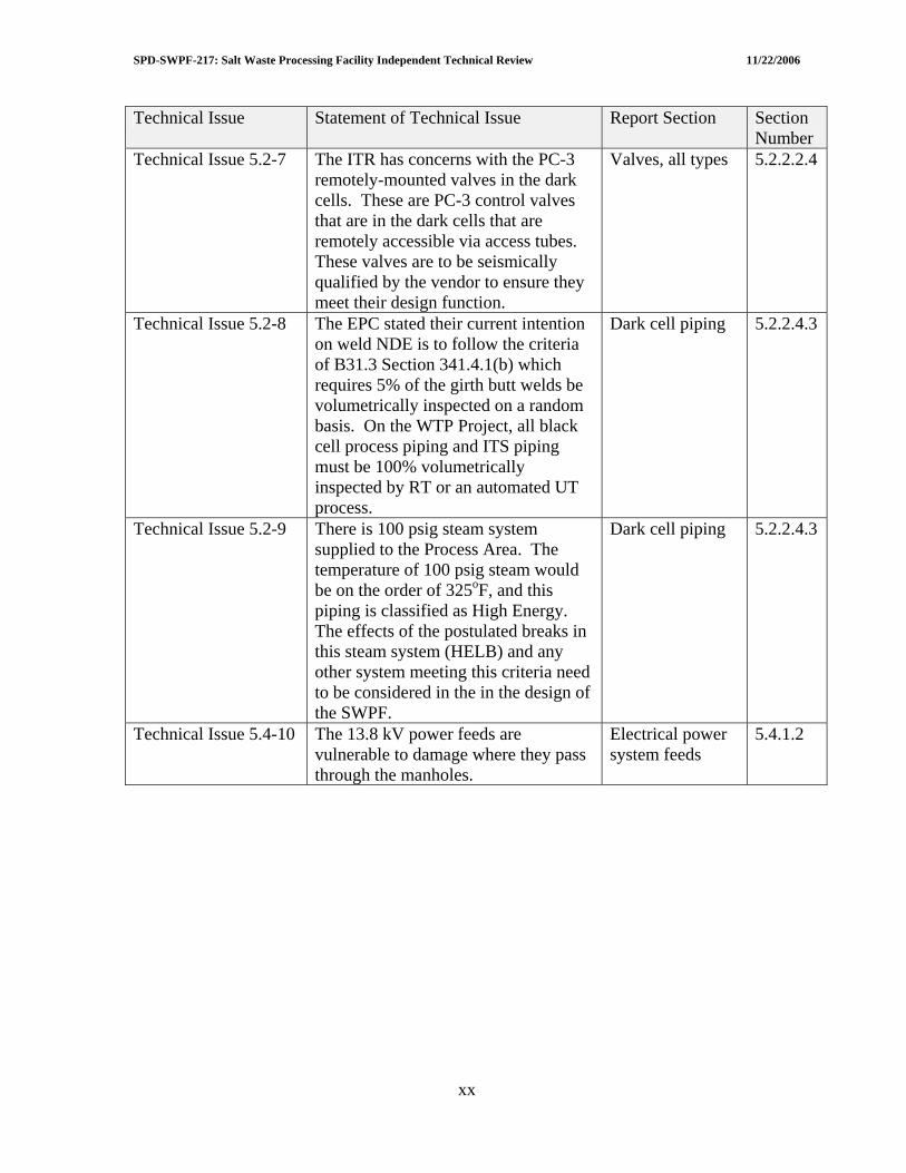
Technical Issue Statement of Technical Issue Report Section Section Number
Technical Issue 5.2-7 The ITR has concerns with the PC-3 remotely-mounted valves in the dark cells. These are PC-3 control valves that are in the dark cells that are remotely accessible via access tubes. These valves are to be seismically qualified by the vendor to ensure they meet their design function.
Valves, all types 5.2.2.2.4
Technical Issue 5.2-8 The EPC stated their current intention on weld NDE is to follow the criteria of B31.3 Section 341.4.1(b) which requires 5% of the girth butt welds be volumetrically inspected on a random basis. On the WTP Project, all black cell process piping and ITS piping must be 100% volumetrically inspected by RT or an automated UT process.
Dark cell piping 5.2.2.4.3
Technical Issue 5.2-9 There is 100 psig steam system supplied to the Process Area. The temperature of 100 psig steam would be on the order of 325oF, and this piping is classified as High Energy. The effects of the postulated breaks in this steam system (HELB) and any other system meeting this criteria need to be considered in the in the design of the SWPF.
Dark cell piping 5.2.2.4.3
Technical Issue 5.4-10 The 13.8 kV power feeds are vulnerable to damage where they pass through the manholes.
Electrical power system feeds
5.4.1.2
xx
SPD-SWPF-217: Salt Waste Processing Facility Independent Technical Review 11/22/2006
1.0 INTRODUCTION 1.1 BACKGROUND ON THE SRS SALT PROCESSING PROGRAM The Savannah River Site (SRS) in South Carolina is a 300-square-mile U.S. Department of Energy (DOE) complex that has produced nuclear materials for national defense, research, and medical programs since it became operational in 1951. As a waste by-product of this production, there are approximately 36 million gallons of liquid radioactive waste currently stored on an interim basis in 49 underground waste storage tanks. Continued, long-term storage of these liquid radioactive wastes in underground tanks poses an environmental risk (eleven of the SRS tanks have a waste leakage history). Therefore, SRS has, since Fiscal Year (FY)-1995, been removing waste from tanks, pre-treating it; vitrifying it; and pouring the vitrified waste into canisters for long-term disposal. Since FY-1996, over 2,000 canisters of waste have been vitrified. The canisters vitrified to date have all contained only sludge waste. Salt waste processing was suspended in FY-1998 because the existing facility could not cost effectively meet both the safety and production requirements of the Tank Waste System. DOE selection of a new salt processing technology was completed in FY-2001, with the Salt Waste Processing Facility (SWPF) scheduled to be operational in late 2011. The ability to safely process the salt component of the waste stored in underground storage tanks at SRS is a crucial prerequisite for completing high-level waste disposal. The two primary regulatory drivers for waste removal are: the Federal Facilities Agreement and the Site Treatment Plan. The Federal Facilities Agreement requires that the 22 non-compliant tanks be emptied and closed on an approved tank-by-tank schedule. The Site Treatment Plan requires that the processing of all tank waste (both existing and future) be completed by FY-2028. Without a suitable method for salt management, DOE will not be able to place the tank waste facilities in a configuration acceptable for safe closure. 1.2 DESCRIPTION OF SALT WASTE PROCESSING FACILITY A detailed description of SWPF functional requirements is provided in SWPF Functional Specification, P-SPC-J-00002[1]. The primary functions of the SWPF are as follows:
• Accept liquid waste from the F- and H-Area Tank Farms, • Produce streams that meet the criteria for vitrification at the Defense Waste
Processing Facility (DWPF), and • Produce Decontaminated Salt Solution (DSS) that meets the waste acceptance criteria
for the Saltstone Production Facility (SPF). Waste from area tank farms will be pumped to a blending tank for blending to meet the SWPF feed specifications. Approximately 1 Mgal of waste will be prepared at a time. After sampling to ascertain that the blended waste meets feed specifications, the waste will be pumped to a staging tank from where individual batches of 23,200 gallons will be delivered to the SWPF for treatment. The SWPF will process each batch in approximately 22 hours. This will result in an instantaneous maximum capacity of 9.4 Mgal per year.
1

SPD-SWPF-217: Salt Waste Processing Facility Independent Technical Review 11/22/2006
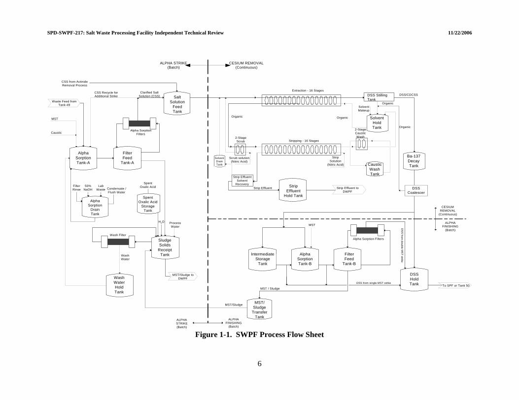
Figure 1-1 shows an upper level SWPF flow sheet. The SWPF treats salt waste in three successive basic unit operations: Alpha Strike Process (ASP), Caustic-Side Solvent Extraction (CSSX), and Alpha Finishing Process (AFP). These processes separate the radioactive elements (primarily actinides, strontium [Sr], and cesium [Cs]) from the bulk salt waste and concentrate them into a relatively small volume. This small volume is then transferred to the Defense Waste Processing Facility (DWPF) for vitrification. The remaining bulk salt waste contains only low levels of radioactive materials and is sent to the Saltstone Production Facility (SPF) for incorporation into grout. The ASP occurs first and is used to separate Sr/actinides from the waste feed by monosodium titanate (MST) adsorption and filtration. The CSSX process follows the ASP and is used to remove Cs from the ASP filtrate by solvent extraction. The AFP is a process step that mimics the ASP and is used as necessary for multistrikes which provide additional Sr/actinide removal downstream of the CSSX process. The ASP is operated as a batch process. Each batch of salt waste received in the SWPF is chemically adjusted and MST is added. The tank contents are mixed to allow the MST to adsorb the Sr and actinides (12 hours for single strike and 6 hours each for multiple strikes). The resulting MST slurry is filtered to produce a (1) concentrated MST/sludge slurry and (2) clarified salt solution (CSS) filtrate. The concentrated MST/sludge slurry is washed to reduce the sodium ion (Na+) concentration and transferred to DWPF, while the CSS is routed to the CSSX process. The second SWPF processing stage is CSSX, which is a continuous flow process utilizing 36 contactor stages for extraction, scrubbing, stripping, and washing of aqueous and organic streams. The Cs is removed by contacting the CSS (aqueous phase) with an engineered solvent (organic phase) in the extraction stage contactors. The Cs-depleted aqueous outlet stream is sent to the AFP for sampling and analysis prior to transfer to the SPF or for another Sr/actinide removal operation. Following extraction, the Cs-enriched solvent is scrubbed to remove impurities (primarily sodium and potassium). The solvent is then contacted with a dilute nitric acid strip solution in the stripping stages, where the Cs is transferred to the aqueous strip effluent. The strip effluent (containing a high concentration of Cs) is sent to DWPF for vitrification. If the Sr/actinide concentration in the CSS sent to the CSSX process is sufficiently low, the aqueous raffinate from the extraction stages (DSS) is sent to the SPF to be solidified with a cementitious grout mixture. If the Sr/actinide concentration in the CSS is too high, the aqueous raffinate from the extraction stages (referred to as Cs-depleted CSS [CDCSS]) is sent to the AFP for a second MST strike. The AFP, which is located downstream of the CSSX process, is the third SWPF processing stage. When the SWPF is operated in single-strike mode, DSS from the CSSX process is sent to the AFP for confirmatory sampling and staging prior to transfer to the SPF. If the Sr/actinide content of the waste feed is sufficiently high that a single MST strike cannot reduce the concentrations low enough for the CDCSS to meet the Saltstone Waste Acceptance Criteria (WAC) limits, the CDCSS will be sent to the AFP to perform a second
2

SPD-SWPF-217: Salt Waste Processing Facility Independent Technical Review 11/22/2006
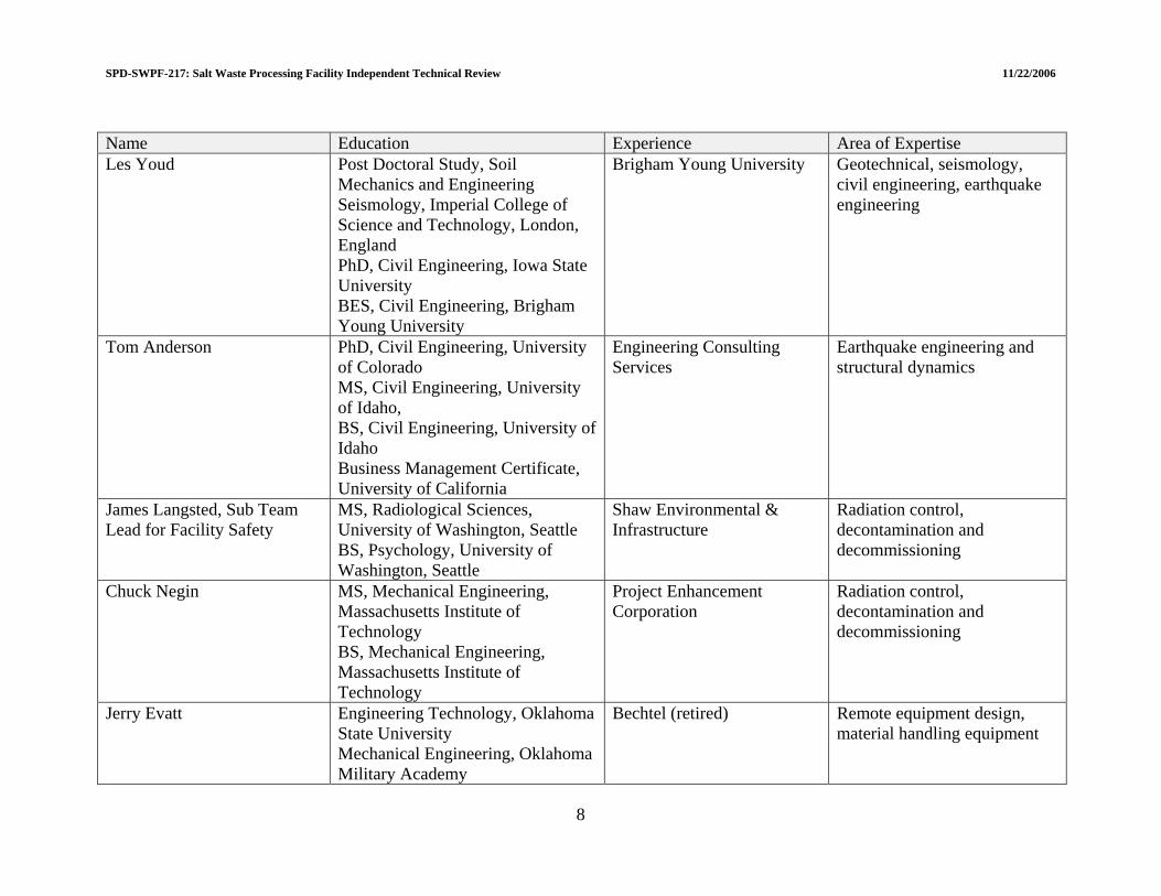
MST strike within the AFP. Since the CDCSS contains a limited concentration of Cs, the process equipment located in the Alpha Finishing Facility (AFF) can be operated and maintained without the extensive shielding and remote handling provisions required in the ASP. 1.3 THE INDEPENDENT REVIEW TEAM DOE established an Independent Technical Review (ITR) Team to review the Preliminary Design of the Salt Waste Processing Facility. This independent review focused on evaluating the sufficiency of design to support development of a baseline cost and schedule (Critical Decision-2 [CD-2]) per DOE Order 413.3A[2]. As such, the design should be mature enough to support development of “detailed, resource loaded schedules and cost estimate for the entire project…”. In addition, the Performance Baseline “shall account for risks and mitigation strategies…”. The results of the review will be used to determine if the current design is mature enough to request CD-2. The scope of the ITR has been defined in the form of Lines of Inquiry (LOI) that served as the framework for review team activities and for selection of review team members. The LOI are listed in the ITR Charter shown in Attachment 1. The LOIs are grouped into three categories: (1) Civil/Structural Design, (2) Facility Safety, and (3) Engineering. The ITR Team focused their attention on the specific subjects identified by the LOIs. DOE indicated that general review priority will be Central Processing Area (CPA), Alpha Finishing Facility (AFF), and remaining support facilities in that order. The ITR Team focused only on the technical aspects of the Preliminary Design and did not review cost and schedule estimates. Further, the ITR did not conduct an independent review safety analysis or peer review all calculations or specifications. Calculations and specifications were reviewed on a selected basis to verify findings and conclusions. The ITR Team was composed of experts with extensive experience in design, engineering and management of chemical processing and radioactive waste management systems. Individual expertise and experience was matched with the LOIs. The Team members’ education and expertise is summarized in Table 1-1 and their resumes are provided in Attachment 2. The ITR was divided into three Sub Teams for each of the three categories identified in the Charter. A leader was selected for each Sub Team to support the Team Leader and to serve as a single point of contact to answer any questions/issues in the appropriate area. The ITR Team started their review on August 29, 2006, after the initial kick-off meeting. The initial review focused on design deliverables that had been completed previously. The 35% design package was provided to DOE on September 15, 2006. A number of design documents were completed or issued as drafts for formal DOE comments during the course of the review. Two Facility Safety and Engineering Sub Teams meetings were held during September and October, and the Civil/Structural Sub Team met once in October. The meetings included presentations, study of design deliverables, discussions with the Engineering, Procurement, and Construction (EPC) staff, and writing sessions.
3

SPD-SWPF-217: Salt Waste Processing Facility Independent Technical Review 11/22/2006
During the ITR Team review, findings were categorized following an approach used in the review of the Demonstration Bulk Vitrification System[3]:
• Fatal Flaws – items which could cause the failure of SWPF and cannot be resolved.
• Technical Issues – items which could result in a failure of the SWPF system to meet established SWPF system performance requirements unless addressed prior to startup of hot operations.
• Areas of Concern – items which may result in a change to design or require additional
testing to determine if the design is adequate (now or later).
• Suggested Improvements – items the SWPF project should consider to enhance safety, cost, schedule, or efficiency during the test operations, final design, commissioning and startup.
• Positive Findings - items that the ITR Team felt were commendable and deserved
recognition. The categorization was conducted by the Team Leader and the three Sub Team Leaders. Although qualitative in nature, the categorization process was effective in identifying the highest priority findings. Findings are numbered using the two-digit section number in the report where they are identified, and then each category of finding is numbered sequentially throughout the report. For example, Area of Concern 3.1-2 is found in Section 3.1, Central Processing Area, and is the second Area of Concern in the report. The corresponding recommendation for this Area of Concern is Recommendation AC 3.1-2. A report summarizing the findings in the review was requested by DOE no later than November 22, 2006. This will support providing a completed technical assessment to the DOE-Headquarters External Independent Review group. 1.4 REPORT ORGANIZATION This report follows the ITR lines of inquiry categories: Civil/Structural design; Facility Safety; and Engineering. Each section incorporates evaluation of specific criteria under the LOI, and summary of the abbreviated responses to the LOI is presented in Table 6-1. Also, a summary table is presented at the end of each subsection that provides the ITR assessment of each relevant item or deliverable. Attachment 3 is a listing of the categorized findings and recommendations. 1.5 REFERENCES (1) P-SPC-J-00002, Revision 0, Salt Waste Processing Facility Functional Specification.
Parsons, Aiken, South Carolina. January 2004.
4
SPD-S
WPF-217: Salt Waste Processing Facility Independent Technical Review 11/22/2006
5
(2) DOE O 413.3A, Section 5.d.(3), Project and Project Management for the Acquisition of Capital Assets. U.S. Department of Energy. July 28, 2006.
(3) RPP-31314, A Comprehensive Technical Review of the Demonstration Bulk Vitrification System. Bechtel, Richland, Washington. September 28, 2006.
SPD-SWPF-217: Salt Waste Processing Facility Independent Technical Review 11/22/2006
AlphaSorptionTank-A
FilterFeed
Tank-A
IntermediateStorage
Tank
AlphaSorptionTank-B
FilterFeed
Tank-B
MST/Sludge
TransferTank
SaltSolution
FeedTank
Waste Feed fromTank-49
MST
CSS Recycle forAdditional Strike
Clarified SaltSolution (CSS)
DSSHoldTank
Ba-137DecayTankCaustic
WashTank
SolventHoldTank
DSS/CDCSS
Organic
Organic
SolventMakeup
Scrub solution(Nitric Acid)
Organic
Strip EffluentSolvent
RecoveryStrip Effluent
SolventDrainTank
Extraction - 16 Stages
Stripping - 16 Stages
Organic
2-StageScrub
2-StageCausticWash
StripSolution
(Nitric Acid)
MST / SludgeTo SPF or Tank 50
MST/Sludge
Strip Effluent toDWPF
Alpha Sorption Filters
MST
Alpha SorptionFilters
DSS from single MST strike
DS
Sfrom
doubleM
ST
strike
ALPHASTRIKE(Batch)
ALPHAFINISHING
(Batch)
ALPHAFINISHING
(Batch)
CESIUMREMOVAL
(Continuous)
Caustic
CSS from ActinideRemoval Process
StripEffluent
Hold Tank
DSS StillingTank
DSSCoalescer
SludgeSolids
ReceiptTank
WashWaterHoldTank
ProcessWater
WashWater
Wash Filter
MST/Sludge toDWPF
AlphaSorption
DrainTank
FilterRinse
50%NaOH
LabWaste Condensate /
Flush Water
SpentOxalic Acid
StorageTank
SpentOxalic Acid
H2O
ALPHA STRIKE(Batch)
CESIUM REMOVAL(Continuous)
Figure 1-1. SWPF Process Flow Sheet
6

SPD-SWPF-217: Salt Waste Processing Facility Independent Technical Review 11/22/2006
Table 1-1. Independent Technical Review Expertise Name Education Experience Area of Expertise Harry Harmon, Team Lead PhD, Inorganic and Nuclear
Chemistry, University of Tennessee BS, Chemistry, Carson-Newman College, Jefferson City, TN
Technology Development Manager, Pacific Northwest National Laboratory
Nuclear materials processing, radioactive waste management
Peter Lowry, Sub Team Lead for Civil/Structural
Graduate studies, Instrumentation and Control systems, Idaho State University BS, Engineering, Idaho State University
Pacific Northwest National Laboratory
Nuclear safety engineer, integrated safety management
Carl Costantino PhD, Illinois Institute of Technology MSCE, Columbia University BCE, City of College of New York
City of College of City University of New York
Civil engineering, seismic analysis
Robert Kennedy PhD, Structural Engineering, Stanford University MS, Structural Engineering, Stanford University BS, Civil Engineering, Stanford University
Private Consultant Structural engineering, seismic design of nuclear facilities
Loring Wyllie MS, Structural Engineering, University of California BS, Civil Engineering, University of California
Degenkolb Engineers Structural engineering, seismic evaluations
John Christian PhD, MS, and BS, Civil Engineering, Massachusetts Institute of Technology
Stone & Webster (retired) Geotechnical engineering, soil dynamics
7
SPD-SWPF-217: Salt Waste Processing Facility Independent Technical Review 11/22/2006
Name Education Experience Area of Expertise Les Youd Post Doctoral Study, Soil
Mechanics and Engineering Seismology, Imperial College of Science and Technology, London, England PhD, Civil Engineering, Iowa State University BES, Civil Engineering, Brigham Young University
Brigham Young University Geotechnical, seismology, civil engineering, earthquake engineering
Tom Anderson PhD, Civil Engineering, University of Colorado MS, Civil Engineering, University of Idaho, BS, Civil Engineering, University of Idaho Business Management Certificate, University of California
Engineering Consulting Services
Earthquake engineering and structural dynamics
James Langsted, Sub Team Lead for Facility Safety
MS, Radiological Sciences, University of Washington, Seattle BS, Psychology, University of Washington, Seattle
Shaw Environmental & Infrastructure
Radiation control, decontamination and decommissioning
Chuck Negin MS, Mechanical Engineering, Massachusetts Institute of Technology BS, Mechanical Engineering, Massachusetts Institute of Technology
Project Enhancement Corporation
Radiation control, decontamination and decommissioning
Jerry Evatt Engineering Technology, Oklahoma State University Mechanical Engineering, Oklahoma Military Academy
Bechtel (retired) Remote equipment design, material handling equipment
8

SPD-SWPF-217: Salt Waste Processing Facility Independent Technical Review 11/22/2006
Name Education Experience Area of Expertise Richard Stark MS, Nuclear Engineering, Carnegie-
Mellon University BS, Electrical Engineering, Carnegie-Mellon University
Director, Office of Facility Operations Support, Department of Energy
Integrated safety management; environment, safety and health
Todd LaPointe Graduate of the U.S. Naval Nuclear Engineering Program, Orlando, FL BS, Marine Engineering w/minors in Nuclear Engineering and Management, Maine Maritime Academy
General Engineer, U.S. Department of Energy (EM-3.2); Operations Management, ESE Central Technical Authority
Nuclear operations, integrated safety management
Norman Moreau MSA, Software Engineering Administration, Central Michigan University BS, Mechanical Engineer, Colorado State University
President and Senior Management Consultant, Theseus Professional Services, LLC
Quality assurance
Art Etchells PhD, Chemical Engineering, University of Delaware MS, University of Pennsylvania BS, University of Pennsylvania
DuPont (retired) Process engineering, mixing technology
Oliver Block PhD, Nuclear Engineering, Kansas State University MS, Nuclear Engineering, Kansas State University BS, Chemical Engineering, University of Nebraska
CWI, Idaho Cleanup Project Process engineering, nuclear operations
Timothy Adams MS, Engineering, University of Pittsburgh BS, Mechanical Engineering, University of Pittsburgh
Stevenson & Associates Mechanical engineering
9

WPF-217: Salt Waste Processing Facility Independent Technical Review 11/22/2006
10
Name Education Experience Area of Expertise Stephen Gosselin MS, Mechanical Engineering,
University of North Carolina BS, Mechanical Engineering, California State Polytechnic University
Pacific Northwest National Laboratory
Mechanical engineering, solid mechanics, fracture mechanics
Patrick Corcoran HNC, Electrical/Electronic, Hendon College of Technology, London, England
Bechtel (retired) Electrical engineering, engineering management
Ken Cooper PhD, University of Pittsburgh MSES, Rensselaer Polytechnic Institute BSEE, University of Pittsburg
Westinghouse (retired) Instrumentation and controls
Heating, ventilation, and air conditioning; testing and surveillance of gas treatment systems
Kari McDaniel BS, Mechanical Engineering, Portland State University
Polestar, Hanford
George Krauter, Sub Team Lead for Engineering
MS, Physics, Naval Postgraduate School BCE, Rensselaer Polytechnic Institute BS, US Naval Academy
Stone & Webster (retired) Project management, construction management
SPD-S

SPD-S
WPF-217: Salt Waste Processing Facility Independent Technical Review 11/22/2006
11
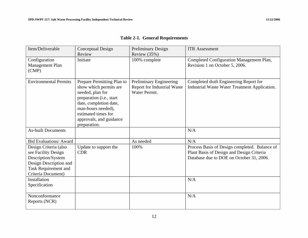
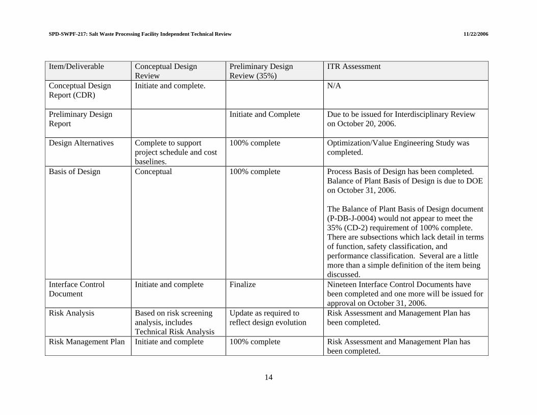
2.0 OVERALL PROJECT STATUS 2.1 GENERAL PROJECT REQUIREMENTS The Department of Energy issued a procedure (Design Documentation Administration for the Salt Waste Processing Facility, SPD-SWPF-002[1]) to establish formal guidelines concerning the review, acceptance, and control of design documents for the Salt Waste Processing Facility. At the 35% level of design completion, the EPC contractor is expected to submit a Preliminary Design (about 35%) package, a draft Preliminary Documented Safety Analysis, and a Critical Decision-2 package. Appendix B of the DOE procedure is a Design Review Deliverable Matrix that lists each item or deliverable and provides the expected status of each item or deliverable at various stages of design. The specific status of deliverables in each design area (as listed in Appendix B) was assessed by the ITR Team as part of the review. The results are provided as summary tables in each major section of the report below (Sections 3.0, 4.0, and 5.0). The procedure also lists a number of General Requirements that include management documents, design criteria, design reports, systems descriptions, and other higher tier planning documents. The status of these General Requirements is summarized in Table 2-1. The General Requirements are essentially complete. 2.2 REFERENCES (1) SPD-SWPF-002, Revision 1, Design Documentation Administration for the Salt
Waste Processing Facility. U.S. Department of Energy-Savannah River Operations Office, Aiken, South Carolina. August 2006.
SPD-SWPF-217: Salt Waste Processing Facility Independent Technical Review 11/22/2006
Table 2-1. General Requirements Item/Deliverable Conceptual Design
Review Preliminary Design Review (35%)
ITR Assessment
Configuration Management Plan (CMP)
Initiate 100% complete Completed Configuration Management Plan, Revision 1 on October 5, 2006.
Environmental Permits
Prepare Permitting Plan to show which permits are needed, plan for preparation (i.e., start date, completion date, man-hours needed), estimated times for approvals, and guidance preparation.
Preliminary Engineering Report for Industrial Waste Water Permit.
Completed draft Engineering Report for Industrial Waste Water Treatment Application.
As-built Documents
N/A
Bid Evaluations/ Award As needed N/A Design Criteria (also see Facility Design Description/System Design Description and Task Requirement and Criteria Document)
Update to support the CDR
100% Process Basis of Design completed. Balance of Plant Basis of Design and Design Criteria Database due to DOE on October 31, 2006.
Installation Specification
N/A
Nonconformance Reports (NCR)
N/A
12
SPD-SWPF-217: Salt Waste Processing Facility Independent Technical Review 11/22/2006
Item/Deliverable Conceptual Design Review
Preliminary Design ITR Assessment Review (35%)
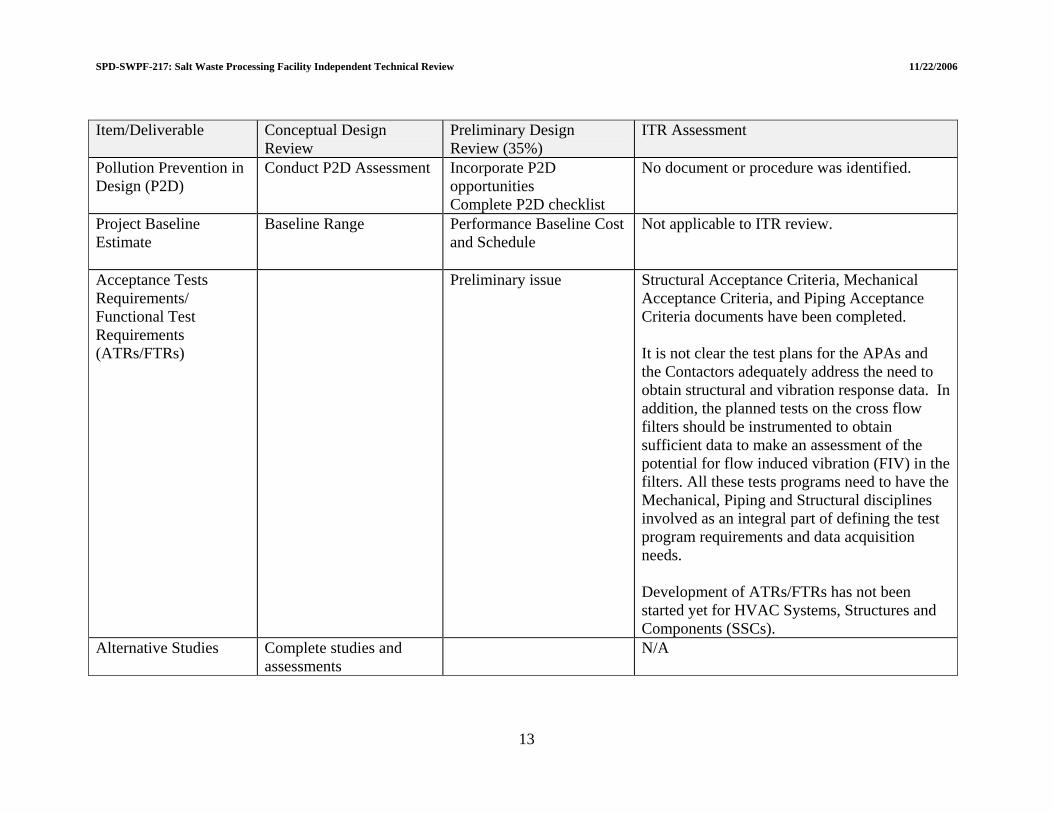
Pollution Prevention in Design (P2D)
Conduct P2D Assessment Incorporate P2D opportunities Complete P2D checklist
No document or procedure was identified.
Project Baseline Estimate
Baseline Range Performance Baseline Cost and Schedule
Not applicable to ITR review.
Acceptance Tests Requirements/ Functional Test Requirements (ATRs/FTRs)
Preliminary issue Structural Acceptance Criteria, Mechanical Acceptance Criteria, and Piping Acceptance Criteria documents have been completed. It is not clear the test plans for the APAs and the Contactors adequately address the need to obtain structural and vibration response data. In addition, the planned tests on the cross flow filters should be instrumented to obtain sufficient data to make an assessment of the potential for flow induced vibration (FIV) in the filters. All these tests programs need to have the Mechanical, Piping and Structural disciplines involved as an integral part of defining the test program requirements and data acquisition needs. Development of ATRs/FTRs has not been started yet for HVAC Systems, Structures and Components (SSCs).
Alternative Studies
Complete studies and assessments
N/A
13
SPD-SWPF-217: Salt Waste Processing Facility Independent Technical Review 11/22/2006
Item/Deliverable Conceptual Design Review
Preliminary Design ITR Assessment Review (35%)
Conceptual Design Report (CDR)
Initiate and complete. N/A
Preliminary Design Report
Initiate and Complete Due to be issued for Interdisciplinary Review on October 20, 2006.
Design Alternatives
Complete to support project schedule and cost baselines.
100% complete Optimization/Value Engineering Study was completed.
Basis of Design
Conceptual 100% complete Process Basis of Design has been completed. Balance of Plant Basis of Design is due to DOE on October 31, 2006. The Balance of Plant Basis of Design document (P-DB-J-0004) would not appear to meet the 35% (CD-2) requirement of 100% complete. There are subsections which lack detail in terms of function, safety classification, and performance classification. Several are a little more than a simple definition of the item being discussed.
Interface Control Document
Initiate and complete Finalize Nineteen Interface Control Documents have been completed and one more will be issued for approval on October 31, 2006.
Risk Analysis
Based on risk screening analysis, includes Technical Risk Analysis
Update as required to reflect design evolution
Risk Assessment and Management Plan has been completed.
Risk Management Plan
Initiate and complete 100% complete Risk Assessment and Management Plan has been completed.
14

SPD-SWPF-217: Salt Waste Processing Facility Independent Technical Review 11/22/2006
Item/Deliverable Conceptual Design Review
Preliminary Design ITR Assessment Review (35%)
System Design Description
Initiate system delineations Twelve system description documents have been completed and one more was issued for approval on October 9, 2006.
3D model
Overall conceptual design with major equipment shown to define space requirements and quantities for estimating as applicable.
Refine to include design information as design evolves. Produce quantity reports and drawings.
The 3D model for this project is completely electronic and therefore it is difficult to judge its completeness or correctness. A presentation and review was conducted with the EPC Piping Group. Based on that review the 35% (CD-2) requirements are judged to have been met.
Safeguards and Security Requirements
Finalize Facility Security Plan has been completed.
Value Engineering Perform Value Engineering Studies
Preliminary Design Value Engineering (Finalize)
Value Engineering Study has been completed.
15
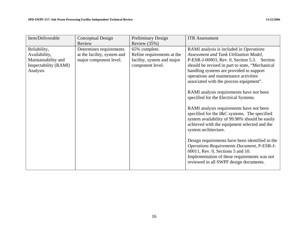
WPF-217: Salt Waste Processing Facility Independent Technical Review 11/22/2006
16
Item/Deliverable Conceptual Design Review
Preliminary Design Review (35%)
ITR Assessment
Reliability, Availability, Maintainability and Inspectability (RAMI) Analysis
Determines requirements at the facility, system and major component level.
65% complete. Refine requirements at the facility, system and major component level.
RAMI analysis is included in Operations Assessment and Tank Utilization Model, P-ESR-J-00003, Rev. 0, Section 5.3. Section should be revised in part to state, “Mechanical handling systems are provided to support operations and maintenance activities associated with the process equipment”. RAMI analysis requirements have not been specified for the Electrical Systems. RAMI analysis requirements have not been specified for the I&C systems. The specified system availability of 99.98% should be easily achieved with the equipment selected and the system architecture. Design requirements have been identified in the Operations Requirements Document, P-ESR-J-00011, Rev. 0, Sections 5 and 10. Implementation of these requirements was not reviewed in all SWPF design documents.
SPD-S
SPD-SWPF-217: Salt Waste Processing Facility Independent Technical Review 11/22/2006
3.0 CIVIL/STRUCTURAL DESIGN Findings of the Civil/Structural Independent Review are summarized in Table 3-1. 3.1 CENTRAL PROCESSING AREA (CPA) 3.1.1 CPA Civil/Structural Design 3.1.1.1 Summary of response to LOI I.a.1 “Does structural design progress on the CPA meet 35% design expectations, as defined in Salt Processing Division procedure SPD-SWPF-002, and meet Performance Category (PC)-3 design requirements in accordance with DOE STD-1020, -1021, -1022, and -1023?” The structural design progress on the CPA does meet the 35% design expectations for the project. The structural configuration is significantly improved from a previous 2005 review and compliments the design team for that achievement. The ITR also wishes to compliment the EPC for a clear and well-written Structural Acceptance Criteria document[1]. Some minor comments were provided directly to the EPC at the review meeting for the next revision to this document. This ITR review did not perform an independent review of the structural calculations completed at this time. The review relied on results of the analysis and calculations provided by EPC staff at the review meeting, responses to questions raised by the ITR and review of selected documents such as the Structural Acceptance Criteria. While specific Technical Issues and Concerns are being raised in this report, the ITR believes that the design team can properly address those findings within the normal design evolution process. The ITR believes that the 35% design of the CPA, with the corrections or modifications suggested, will meet the PC-3 design requirements of DOE Standards 1020, 1021, 1022, and 1023. 3.1.1.2 Seismic analysis The criteria and approaches being used for the seismic analysis of the CPA have been reviewed and there are concerns with regard to the current seismic analyses performed for the CPA. These concerns are summarized under the following seven topic areas. 3.1.1.2.1 In-structure response spectra The computed in-structure response spectra (ISRS) obtained from the seismic analyses was reviewed. The ISRS was generated from time domain integration of the lumped mass stick model of the CPA, using the GTStrudL® computer code. The lumped mass model essentially uses single sticks to represent the shear and bending properties of the CPA, incorporating rigid diaphragm elements to represent the various floor members, including the facility base mat. The analyses performed for the various soil-structure-interaction load cases use a
17

SPD-SWPF-217: Salt Waste Processing Facility Independent Technical Review 11/22/2006
frequency-independent spring/dashpot element to account for soil-structure-interaction effects on building response. The spring and dashpot elements were generated from the impedance functions for a uniform half-space provided in American Society of Civil Engineers (ASCE) Standard 4-98[2] for translational and rotational degrees of freedom. The element properties, in turn, were determined by averaging low strain shear wave velocity and Poisson's ratio values over specified depths below the foundation slab. The issues associated with this process are discussed in the ITR summary comments listed below. They have to do with (a) the use of low strain velocity values as opposed to iterated velocities associated with seismic induced strains, (b) use of Poisson's ratio as opposed to recommended values of P-wave velocities, and (c) uniformity of the velocity profile beneath the base mat. The viscous damping values for each seismic degree of freedom were selected by using the two-parameter Rayleigh damping model. Design floor response spectra were then determined by enveloping the results of the computed floor response spectra and the input free-field ground spectra. There is a serious issue with this process on two counts. First, the computed floor response spectra, even at the base mat level (Elevation 100) were significantly below the free-field input spectra at low frequency. This result is contrary to the experience of the ITR members found from studies for other facilities similar in size and type to the CPA. Secondly, it is not common practice to envelop the free-field input spectrum with the computed ISRS to obtain the design smoothed and broadened design ISRS. Rather, common practice uses the computed floor spectra alone to generated smoothed and broadened design spectra. Since the meeting, it has been found that the floor response spectra presented are based on relative accelerations and not absolute accelerations. The corrected absolute floor response spectra are now, as expected, similar to the free-field input ground motion at low frequencies. It is presumed that the project will modify the floor response and generate envelop smoothed and broadened design ISRS that are based on computed in-structure absolute acceleration only. The comparison of the corrected ISRS with the current envelop design spectra indicate that the design response spectra are unconservative over a significant frequency range. Therefore, the corrected ISRS from all seismic cases need to be obtained to generate new smoothed and broadened design spectra. It is also strongly recommended, however, that corroborating analyses be performed, using other computer codes (e.g., SASSI and/or SAP) to ensure that the results obtained from the GTStrudL® analyses are adequate. Technical Issue 3.1-1: The ITR expressed serious concern with the adequacy of the computed in-structure response spectra from the lumped mass stick model soil-structure-interaction analyses. The procedure needs to be modified to generate new smoothed and broadened design floor spectra based on absolute accelerations. The current design envelop spectra are unconservative over significant frequency ranges of interest for design of SSCs. The adequacy of the GTStrudL® lumped mass model spectral results should be verified to ensure that they are sufficiently conservative.
18
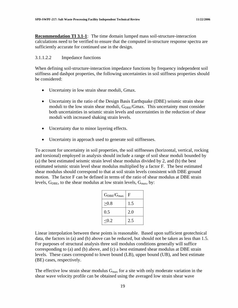
SPD-SWPF-217: Salt Waste Processing Facility Independent Technical Review 11/22/2006
Recommendation TI 3.1-1: The time domain lumped mass soil-structure-interaction calculations need to be verified to ensure that the computed in-structure response spectra are sufficiently accurate for continued use in the design. 3.1.1.2.2 Impedance functions When defining soil-structure-interaction impedance functions by frequency independent soil stiffness and dashpot properties, the following uncertainties in soil stiffness properties should be considered:
• Uncertainty in low strain shear moduli, Gmax.
• Uncertainty in the ratio of the Design Basis Earthquake (DBE) seismic strain shear moduli to the low strain shear moduli, GDBE/Gmax. This uncertainty must consider both uncertainties in seismic strain levels and uncertainties in the reduction of shear moduli with increased shaking strain levels.
• Uncertainty due to minor layering effects.
• Uncertainty in approach used to generate soil stiffnesses.
To account for uncertainty in soil properties, the soil stiffnesses (horizontal, vertical, rocking and torsional) employed in analysis should include a range of soil shear moduli bounded by (a) the best estimated seismic strain level shear modulus divided by 2, and (b) the best estimated seismic strain level shear modulus multiplied by a factor F. The best estimated shear modulus should correspond to that at soil strain levels consistent with DBE ground motion. The factor F can be defined in terms of the ratio of shear modulus at DBE strain levels, GDBE, to the shear modulus at low strain levels, Gmax, by:
GDBE/Gmax F
>0.8 1.5
0.5 2.0
<0.2 2.5 Linear interpolation between these points is reasonable. Based upon sufficient geotechnical data, the factors in (a) and (b) above can be reduced, but should not be taken as less than 1.5. For purposes of structural analysis three soil modulus conditions generally will suffice corresponding to (a) and (b) above, and (c) a best estimated shear modulus at DBE strain levels. These cases correspond to lower bound (LB), upper bound (UB), and best estimate (BE) cases, respectively. The effective low strain shear modulus Gmax for a site with only moderate variation in the shear wave velocity profile can be obtained using the averaged low strain shear wave
19

SPD-SWPF-217: Salt Waste Processing Facility Independent Technical Review 11/22/2006
velocity VS,Low obtained over an appropriate depth below the foundation. Similarly, the effective DBE seismic strain shear modulus GDBE can be obtained using the averaged seismic strain shear wave velocity VS,DBE obtained from a shear wave convolution analysis of the site soil profile. Poisson’s ratio υ should be obtained from the ratio of VS,DBE to the averaged seismic strain compression wave velocity VP,DBE, obtained from a compression wave convolution analysis of the site soil profile by:
[ ][ ]V
V
R12R21
−−
=υ (Eq. 3.1.1.2-1)
(Eq. 3.1.1.2-2) ( 2
DBE,PDBE,SV V/VR = ) This same υ can be used as an adequate approximation for the LB, UB, and BE soil cases for determining the soil stiffness and dashpot properties. For sites with only moderate variation in the shear wave velocity profile, Newmark, N.M., et.al., 1980[3] makes the following recommendations for estimating frequency independent soil dashpot properties. Geometric damping (radiation energy dissipation) dashpot properties should be taken as the following ratios of the frequency independent elastic half-space theoretical values:
• Horizontal to be taken as 75% of the theoretical value.
• Vertical to be taken as 75% of the theoretical value.
• Rotation (rocking and torsional) to be taken at 100% of the theoretical value. Soil material energy dissipation appropriate for the soil seismic strain levels can be added to the above defined geometric damping. Area of Concern 3.1-1: Currently, the frequency-independent soil-structure-interaction impedance functions being used in the seismic analysis of the CPA are based on low-strain shear wave velocities. These impedance functions should be revised so as to be based on seismic-strain shear wave velocities. Furthermore, the geometric damping dashpot properties being used are only applicable for a site that can be modeled as an elastic half-space. These dashpot properties for translational response are too high because they do not consider the moderate layering effects that exist at the SWPF site. Recommendation AC 3.1-1: The soil-structure-interaction impedance functions used in the seismic analysis of the CPA need to be revised to be consistent with the seismic strain level shear wave velocities and the layering effects that exist at the SWPF site.
20
SPD-SWPF-217: Salt Waste Processing Facility Independent Technical Review 11/22/2006
3.1.1.2.3 Vertical/Horizontal (V/H) ratio for input ground motion vertical response spectra
The criteria document used to guide the design indicates in Section 6.5.3 that the vertical input motion will be developed using a response spectral V/H ratio of 2/3 at all frequencies; that is, the vertical spectrum will be defined as 2/3 of the horizontal spectrum at all frequencies. The guidance for this recommendation is cited as ASCE Standard 4-98[2]. However, ASCE Standard 4-98 limits this assumption to cases where the input ground motion spectra are controlled at all frequencies of interest to far-field controlling events. Based on review of the current hazard documents available for the site, the ITR believes that the seismic hazard, particularly at higher frequencies of interest (above 10 hz) are strongly influenced by local seismic events. The appropriate V/H values for these cases are higher than 2/3. Since the existing and draft revised seismic hazard results include descriptions of both horizontal and vertical design spectra, it is recommended that the project use vertical spectra, and corresponding enveloping time histories, defined by the site. The V/H design spectra will therefore be consistent and appropriate for the PC-3 design. Technical Issue 3.1-2: The current structural acceptance document indicates that the V/H ratio being used for design of the CPA does not agree with the recommendations available in the site-wide seismic hazard documents. Recommendation TI 3.1-2: The project team should replace the vertical ground motion spectrum developed from the constant V/H ratio model to that consistent with the available site-wide seismic hazard recommendation. 3.1.1.2.4 Vertical floor amplification The vertical lumped mass stick model is adequate for developing in-structure (floor) response spectra at the junction of walls and floors. However, for equipment mounted on floors more than several feet away from the wall-floor junction, vertical floor amplification due to floor flexibility must be considered unless the floor can be considered to be rigid. The floor can be considered to be essentially rigid when its cracked fundamental vertical natural frequency exceeds the frequency at which the Fourier Amplitude of the vertical input motion drops to less than 10% of the peak vertical Fourier Amplitude. Area of Concern 3.1-2: The vertical ISRS does not account for the vertical amplification due to vertical floor flexibility. These vertical ISRS are not applicable for defining the input to equipment mounted on floors more than several feet away from the wall-floor junction. Recommendation AC 3.1-2: The effect of vertical floor flexibility needs to be included in the vertical in-structure response spectra for floors with equipment mounted away from the wall-floor junction.
21
SPD-SWPF-217: Salt Waste Processing Facility Independent Technical Review 11/22/2006
3.1.1.2.5 Benchmark finite element model element size adequacy for determining out-of-plane moments and shears
If the finite element model is used to determine out-of-plane moments and shears, it is necessary to demonstrate that the number of elements between support points is adequate for determining these out-of-plane moments and shears. It is suggested that a fixed-fixed beam model subjected to uniform load be used to determine the minimum number of elements needed to compute end negative moments and shears, and center positive moments within 10% accuracy. The resulting minimum number of elements should be used between support points for all walls and slabs with high computed out-of-plane demands. Area of Concern 3.1-3: The finite element model element size has not been demonstrated to be adequate for determining the out-of-plane moments and shears in walls and slabs. Recommendation AC 3.1-3: The finite element model element size needs to be demonstrated to be adequate for determining the out-of-plane moments and shears in walls and slabs. 3.1.1.2.6 Validation of lumped mass and finite element models against each other It is our understanding that the lumped mass model will be used to compute the in-structure response spectrum, and that the finite element model will be used to compute shears and moments in the structure. It is necessary to demonstrate similarity between the two models. This similarity can be demonstrated by comparing either of the following fixed base analyses using both models:
• Demonstrate that both models produce very similar horizontal deformed shapes when subjected to one g horizontal static loading.
• Demonstrate very similar modal frequencies and mode shapes for the two most
dominant modes in each of the horizontal directions. In addition, it is necessary to compare the overall story shears computed from both models for the seismic input. The overall story shears computed from the finite element model need to be similar or more conservative than those computed from the lumped mass model. Area of Concern 3.1-4: The lumped mass and finite element models of the CPA have not been adequately verified against each other. Recommendation AC 3.1-4: The lumped mass and finite element models of the CPA need to be more extensively verified against each other.
22

SPD-SWPF-217: Salt Waste Processing Facility Independent Technical Review 11/22/2006
3.1.1.2.7 Realistically model roof diaphragm In the GTStrudL® FEM model, the composite roofs of the CPA were apparently modeled only as 12-inch thick concrete slabs ignoring the stiffness of the composite beams. This resulted in very flexible slabs for vertical motions with excessive vertical seismic motions. These roof slabs should be realistically modeled with their vertical stiffness as composite systems for the next version of the GTStrudL® analysis. Area of Concern 3.1-5: The vertical stiffness of the composite roof slabs of the CPA have not been realistically modeled. Recommendation AC 3.1-5: The ITR recommends the composite roofs of the CPA should be realistically modeled with their vertical stiffness as composite systems for the next version of the GTStrudL® analysis. 3.1.1.3 Design The structural design of the CPA was reviewed by the ITR. This current design has improved many structural features from the previous design reviewed in 2005. There is one concern regarding the seismic bracing of the high roof and a few comments regarding the current status of the design. 3.1.1.3.1 Roofing not rigid diaphragm The high roof diaphragm at Elevation 176 is approximately 225 feet by 41 feet in plan. For north-south seismic forces, this diaphragm is too flexible to transfer the majority of the seismic forces to the end walls on the lines 1.5 and 11. This results in a sizeable portion of the seismic forces at this upper level being transferred in/out of plane flexure and shear in the walls on lines E.2 and F.9 above Elevation 156. This is clearly seen in the summarized analysis results. The ITR was told that about 50% of the seismic forces above Elevation 156 are currently resisted by out of plane wall flexure and shear. Area of Concern 3.1-6: Concrete walls are intended to resist seismic forces by in-plane responses by our building codes. If the walls on line E.2 and F.9 continue to resist these significant out of plane seismic forces, these walls should be detailed as a series of interconnected columns with transverse reinforcement (horizontal ties) as required for columns in special moment resisting frames. This will add considerable cost to the project and certainly complicate construction. Recommendation AC 3.1-6: The ITR strongly recommends that the design team add two external buttress walls above Elevation 156 on lines 5.8 and 9.2 south of line F.9. Further, the ITR recommends that the walls and buttresses on lines 1.5, 5.8, 9.2, and 11 above Elevation 156 should resist at least 85% of the seismic shear at that level by calculation and those shears should be scaled up so the capacity is adequate to resist 100% of this seismic shear at that level.
23
SPD-SWPF-217: Salt Waste Processing Facility Independent Technical Review 11/22/2006
3.1.1.3.2 Input from geotechnical on deflection from settlement The Geotechnical Report and design recommendations for building settlement have not been completed. For the 35% design an assumption was made which illustrates that building settlement can be very significant for the design of the CPA and possibly dominate the design. For the final design the recommendations of the Geotechnical Report should be followed. If these settlements cause a major impact on the design, the settlement issue may want to be considered a beyond-design-basis effect with the design allowing some inelastic hinges in the structural members to accommodate these settlements should they occur. 3.1.1.3.3 Typical reinforcing steel details The typical details shown on the structural drawings have vertical wall reinforcing bars hooked out from the center of the wall at their base and top. These vertical bars at exterior walls are shown with both faces hooking into the slab. The design team should be aware that these details in that slab-wall joint typically will not develop the flexural strength of the wall. For proper performances, these hooks should be hooked towards the center of the wall. A reference to research documenting this performance is “Reinforced concrete corners and joints subjected to bending moment” by Ingvar H. E. Nilsson in Document D7: 1973 of the National Swedish Building Research. An easier to find summary was published in Journal of the Structural Division ASCE Vol. 102, No. 6, June 1976, pp. 1229-1254. It may be that the basement is thick enough to allow the vertical wall dowels to be developed as straight bars or that out of plane moments are very low so this issue is not a concern. 3.2 SUPPORT FACILITIES 3.2.1 Support Facilities Civil/Structural Design 3.2.1.1 Summary of response to LOI I.b.1 “Does the structural design progress on the Support Facilities meet 35% design expectations as defined in SPD-SWPF-002 and meet PC-1 design requirements in accordance with DOE-STD-1020, -1021, -1022, and -1023?” The structural design progress on the support facilities does meet the 35% design expectations for the project. The EPC accepted many of the previous review recommendations of July 2005 and is using Special Concentric Braced Frames for the seismic bracing system and monolithic foundations. This improves seismic ductility of these portions of the facility. The division of these support facilities into regular rectangular buildings with seismic separations expansion joints simplifies both design and construction. Several of these support facilities, specifically the AFF and the Cold Chemicals Area are being designed as PC-1 structures with enhanced importance factors recognizing their importance to facility performance above routine PC-1 criteria. An independent review of the structural calculations completed at this time was not independently reviewed by the ITR. The ITR relied on results of the analysis and
24
SPD-SWPF-217: Salt Waste Processing Facility Independent Technical Review 11/22/2006
calculations provided by EPC staff at the review meeting, responses to questions raised by the ITR and review of selected documents such as the Structural Acceptance Criteria. Based on the review, the 35% design of the support facilities of the SWPF, as modified to address the Technical Issue noted in Section 3.2.1.2 will meet or exceed the PC-1 design requirements of DOE Standards 1020, 1021, 1022 and 1023. 3.2.1.2 Use of tubes for vertical/diagonal bracing A question regarding the selection of steel sections for the vertical diagonal braces in the support structures was raised during this review. In the original 2005 design, the EPC indicated the use of structural T-sections for these members. In the July 2005 report the ITR suggested a symmetrical steel section would be preferable to the T-sections. In this 35% submittal, the EPC has indicated using hollow-structural steel sections or structural steel tube sections for these members. Thin wall tubes have had serious performance issues in recent earthquakes and the code limits on B to t ratios. However, the ITR is aware that new, unpublished research results are showing further concerns with tube members as diagonal bracing members. In light of this new information, it is recommended that the design team consider either round steel pipe or wide flanged members for these diagonal braces. Technical Issue 3.2-3: The EPC has indicated using hollow structural steel or structural steel tube sections for the diagonal braces. Thin wall rectangular tubes have had serious performance issues in recent earthquakes and new, as yet unpublished, research has added increased concerns about their performance. Recommendation TI 3.2-3: The ITR recommends that the design team consider either round steel pipe or wide flanged members for the vertical diagonal braces in the Support Facilities. 3.2.1.3 Utility connections through expansion joints Concern was expressed regarding the design of utility connections that pass between various SWPF buildings across the four-inch seismic gaps that will experience differential drifts during a seismic event. It was determined that the Piping Systems Structural Integrity Acceptance Criteria[4], (G-ESR-J-00002, Section 6.8.4) specifically addresses the requirement for the piping system structural integrity evaluation to consider the building drift-imposed displacements on piping that crosses the seismic gaps separating the buildings. The imposed movements due to building separation and story drift in the seismic gap joints are provided by the EPC Civil/Structural Group. 3.2.1.4 Waste transfer lines (PC-2) The Piping Systems Structural Integrity Acceptance Criteria, G-ESR-J-00002, should explicitly address the design of the underground PC-2 high activity waste transfer lines from the interface point (Drawing No. C-CX-J-0005) to their entry to the CPA building. These criteria should provide explicit guidance for all required design loads for both the inner and
25
SPD-SWPF-217: Salt Waste Processing Facility Independent Technical Review 11/22/2006
outer piping system, including specifically addressing the magnitude and spatial distribution of both static and dynamic settlement displacements for these lines as provided by the EPC Civil/Structural Group based upon information provided by the geotechnical subcontractor. Area of Concern 3.2-7: Design of the underground PC-2 high activity waste transfer lines are not addressed specifically in the acceptance criteria. Recommendation AC 3.2-7: The ITR recommends that the design team amend the Piping System Structural Integrity Acceptance Criteria to explicitly address the design for all required loads for the underground PC-2 high activity waste transfer lines. Suggested Improvement 3.2-1: It is suggested that the PC-2 underground waste transfer lines be constructed using full penetration, butt welded ductile steel piping. This recommendation is based upon field experience where it has been consistently shown that full penetration, butt welded ductile piping can accommodate very large deformations without failure. A reserve margin is considered appropriate should the settlement displacements be more severe than those recommended by the geotechnical consultant. 3.3 SUBSURFACE DESIGN 3.3.1 Geotechnical Investigations 3.3.1.1 Summary of response to LOI I.c.1 “Does the planned geotechnical investigation support design requirements for the PC-3 CPA?” The geotechnical investigation plan, as currently formulated, does support the design requirements for the PC-3 CPA. The borings and soundings are distributed widely over the site. The borings are distributed on a grid that is approximately 50 ft x 50 ft, which represents a higher density of coverage than has been typical of facilities on this site. The field and laboratory testing programs represent the state of practice in geotechnical engineering, and they should provide a better and more comprehensive description of the soils at this site than has been possible for previous facilities. The field and laboratory testing programs are ongoing, so the geotechnical report has not yet been prepared. Without knowledge of the results of such a testing program, it is not possible to draw conclusions about the geotechnical conditions. The results could agree with prior perceptions of geotechnical conditions, but they could also raise new issues that will have to be addressed. When the geotechnical testing program is completed, it will be necessary to review the results to determine how they affect the geotechnical aspects of the design or whether they have impacts on other design considerations.
26
SPD-SWPF-217: Salt Waste Processing Facility Independent Technical Review 11/22/2006
3.3.1.2 Review of geotechnical data The geotechnical data, when they become available, will provide several input parameters that are important in the design of the SWPF. Examples include estimates of settlements and bearing capacity, but they also include evaluations of the extent and influence of so-called “soft zones.” The geotechnical data can also affect the development of design earthquake spectra and the parameters used as input to soil-structure interaction analyses. The geotechnical data can have important consequences for the overall plant design. Therefore, it is important that the geotechnical data be independently reviewed and evaluated before the results are propagated through the design process. This review has not been carried out because the geotechnical report is not complete. Area of Concern 3.3-8: Without knowledge of the results of the geotechnical testing program, it is not possible to draw conclusions about the geotechnical conditions. The results could agree with prior perceptions of geotechnical conditions, but they could also raise new issues that will have to be addressed. Recommendation AC 3.3-8: When the geotechnical testing program is completed, the ITR recommends additional review of the results to determine how they affect the geotechnical aspects of the design or whether the results have impacts on other design considerations. 3.3.1.3 Comparison of SWPF site soil profile with the SRS site-wide profile Over the years in which the SRS has been in operation, there have been many geotechnical investigations, which have resulted in a generally accepted geologic profile for the site. At each individual site minor modifications have developed as a result of the local exploration program, but the overall picture has remained generally uniform across the site. At the SWPF the exploration and testing program is denser and more extensive than the usual case at SRS. The results of these tests are not yet available. The geotechnical profile developed from previous local investigations give a general picture of the geotechnical conditions that is consistent with the previous understanding. However, it is conceivable that the more elaborate investigation program now underway could yield results that are not consistent with the generally accepted site-wide geotechnical profile. In that case, the implications of the new results will have to be evaluated and incorporated in design. 3.3.1.4 Identification of soft zones The number and spatial distribution of soundings and borings are adequate to identify soft materials in soil profiles and to place bounds on potential areal extents of soft zones. Without access to the data and analyses that will be forthcoming in the geotechnical report, the ITR could not review possible soft zones beneath the site, but the CPT data should be adequate to identify soft zones in individual soil profiles, using the accepted criterion of qt < 15 TST with a thickness > 2 ft. The spacing of soundings at approximately 50 ft intervals in both north-south and east-west directions over the building foot print SWPF is adequate to
27

SPD-SWPF-217: Salt Waste Processing Facility Independent Technical Review 11/22/2006
roughly bound extents of the soft zones. In particular, the grid of soundings extends sufficiently beyond the bounds (> 50 ft) of the CPA building to an accuracy of approximately +/- 50 ft. The Civil Boring Plan indicates that some additional soundings apparently have been placed to further increase the accuracy of possible bounds in some areas. If greater definition of extents of critical soft zones, beyond those provided in the geotechnical report is needed, we understand that some additional CPT soundings could be added to provide additional refinement. Samples were taken from boreholes for laboratory testing to determine soil properties. As noted in Section 3.3.1.1, the suite of tests specified appears adequate to define critical soil properties within soft zone materials, including soil type, consistency, strength and compressibility. 3.3.1.5 Define subsidence model for soft zones that impact foundation of structure The major impact of soft zones on the structure is potential collapse of arches over the soft zones allowing transfer of overburden stresses from the arch to soft materials, causing consolidation of the soft materials and settlement above the materials that could reach the ground surface. Such settlements could impact the foundation of the overlying structure, causing detrimental deformations and strains in structural elements. To analyze structural deformations and strains, the shape of the surficial subsidence zone, complete with settlement contours, is needed. It is understood that one of the requirements of the geotechnical contractor is to develop this settlement information. Without the geotechnical report, this review could not assess the adequacy or correctness of predicted subsidence zones for use in design. Area of Concern 3.3-9: The assumed subsidence bowl used in the 35% level design calculations may or may not be adequate to account for this potential hazard to the structure. Recommendation AC 3.3-9: The ITR recommends the EPC re-evaluate the correctness of the predicted soft zone subsidence model once geotechnical data is available. 3.3.1.6 Seismically generated ground settlement Another major potential geotechnical impact on the structure is differential ground settlement due to pore pressures generated at depth during seismic shaking that later dissipate leading to ground settlement. A requirement of the geotechnical contractor is to estimate volume changes in soils at depth that could occur following earthquakes and subsequent settlements and differential settlements at ground surface due to these volume changes. Again, this review could not evaluate the correctness or adequacy of predicted seismically-induced settlements, but the ITR does reinforce, by these comments, the need for the contractor to provide estimates of magnitudes and spatial distribution of such settlements using procedures and criteria that have been developed and applied elsewhere at the SRS. Area of Concern 3.3-10: The current analysis uses a uniform 3-inch differential settlement assumption for assessing the impact of dynamic settlement.
28
SPD-SWPF-217: Salt Waste Processing Facility Independent Technical Review 11/22/2006
Recommendation AC 3.3-10: The ITR recommends the EPC provide estimates of the magnitudes and spatial distribution of differential ground settlement due to pore pressures generated at depth during seismic shaking using procedures and criteria that have been developed and applied elsewhere at the SRS. 3.4 RISK MANAGEMENT 3.4.1 Structural Risks 3.4.1.1 Summary of response to LOI I.d.1 “Have all structural risks been identified and addressed; do any remain?” Not all structural risks have been identified. The following risks should be incorporated into the SWPF Risk Assessment and Management Plan[5] for purposes of developing mitigation strategies, tracking and regular follow up: 3.4.1.2 Moving forward without geotechnical data The geotechnical data, when they become available, will provide several input parameters that are important in the design of the SWPF as described in detail previously in Section 3.3.1, “Geotechnical Investigation”. These data have the potential to (a) result in higher site design response spectra and floor spectra than used in the preliminary design, (b) result in a differential settlement profile more severe than that used in the preliminary design, and (c) result in the identification of a soft soil layer underlying the site which could change the soil profile used in the soil-structure interaction analysis. These potential results could impact and require redesign of the PC-3 CPA base mat and building, and the junction where the high-level underground waste transfer lines enter the CPA building. 3.4.1.3 Increases to the in-structure response spectra Final geotechnical data could also result in increases to the ISRS which in turn could lead to redesign impacts for the entire building, including equipment and piping systems and components.
29

SPD-SWPF-217: Salt Waste Processing Facility Independent Technical Review 11/22/2006
30
3.4.2 Risks of Conversion from ISO-9001 to NQA-1 3.4.2.1 Summary of response to LOI I.d.2 “Have risks resulting from the conversion from ISO-9001 to NQA-1 been adequately addressed?” The change in project quality standard from ISO-9001 to NQA-1 could have a major impact in two areas with attendant risks of possible unplanned schedule and cost impacts. These arise from the rigorous and highly detailed requirement to verify and validate (V&V) the computer codes used in the dynamic analysis and design efforts to ensure their NQA-1 compliance. It is understood that the V&V effort is already underway, but no quantitative assessment of its adequacy has been made. Further, NQA-1 requirements will impact geotechnical work and analyses, and the requirements will flow down to the geotechnical subcontractors, including transportation of samples and laboratory testing/reporting activities. The EPC has written or revised all but about three of 33 procedures that will implement NQA-1 standards. However, a formal evaluation of the risk of implementation of these procedures and revisions on existing work or the impacts on cost and schedule of future work has not been made. In mid-November the EPC is planning to bring in a QA resource to evaluate the impact of changes to procedures on previous work. The design impacts reflected by the structural risks identified previously (Sections 3.4.1.1 through 3.4.1.3) also need to be included in this evaluation. Suggested Improvement 3.4-2: Three risks, previously unidentified, were defined by the ITR for incorporation into the SWPF Risk Assessment and Management Plan for purposes of developing mitigation strategies, tracking, and regular follow up. They are: (a) the risk to design of moving forward without final geotechnical data, (b) the risk to in-structure response spectra of moving forward without final geotechnical data, and (c) the risk to cost and schedule arising from the change from ISO-9001 to NQA-1 quality standard. 3.5 REFERENCES (1) P-ESR-J-00002, Revision 1, Structural Acceptance Criteria. Parsons, Aiken, South
Carolina. September 22, 2006. (2) ASCE Standard 4-98, Seismic Analysis of Safety Related Structures and Commentary.
American Society of Civil Engineers. (3) Newmark, N.M. Hall, W.J., Kennedy, R.P., Murray, R.C., and Stevenson, J.D., SSRT
Guidelines for SEP Soil-Structures Interaction Review, U.S. Nuclear Regulatory Commission Letter LS05-80-12-035, December 1980
(4) G-ESR-J-00002, Revision 0, Piping Systems Structural Integrity Acceptance Criteria. Parsons, Aiken, South Carolina. September 13, 2006
(5) V-RMP-J-00001, Revision 1, SWPF Risk Assessment and Management Plan. Parsons, Aiken, South Carolina. June 29, 2006.

SPD-SWPF-217: Salt Waste Processing Facility Independent Technical Review 11/22/2006
Table 3-1. Civil/Structural Design Item/Deliverable Conceptual Design
Review Preliminary Design Review (35%)
ITR Assessment
Civil Site Preparation Calculations
Develop to sufficient detail so that civil site procurement and installation specifications can be completed.
Calculations meet 35% design requirements.
Civil Specifications
Prepare documents for the procurement and installation of all civil site facilities (sanitary/storm sewers, excavation/backfill, sheet piling & dewatering, grading, etc.)
Thirteen civil specifications issued to support procurement and installation of all civil site needs for 35% design deliverables.
Cut and Fill Calculations
Initial calculations in support of Project Baseline Estimate and CDR.
Refine calculations in support of major site contract packages (excavation/backfill, grading)
Cut and fill calculations have been completed.
Duct banks
N/A
Engineered Civil Data Sheets
Prepare documents for the procurement and installation of all facilities (tanks).
Appropriate documents to support procurement and installation of all facilities (tanks) are found under Mechanical Equipment, vessels and tanks – not Civil.
31
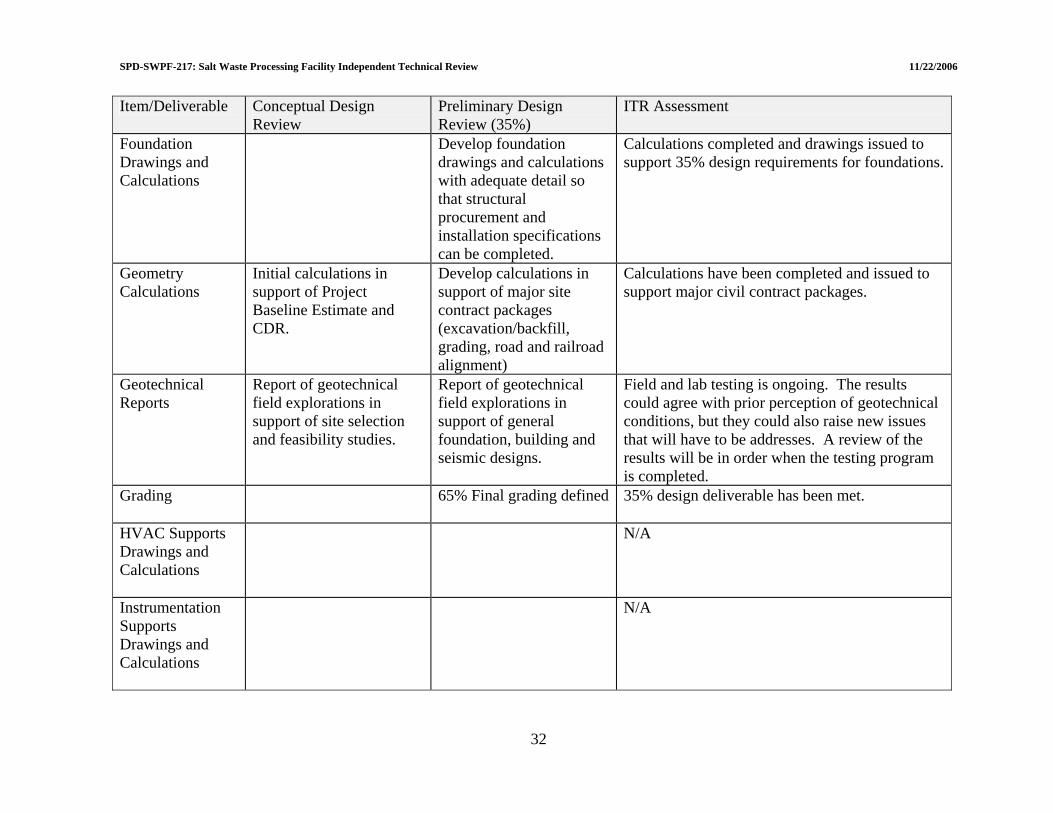
SPD-SWPF-217: Salt Waste Processing Facility Independent Technical Review 11/22/2006
Item/Deliverable Conceptual Design Review
Preliminary Design ITR Assessment Review (35%)
Foundation Drawings and Calculations
Develop foundation drawings and calculations with adequate detail so that structural procurement and installation specifications can be completed.
Calculations completed and drawings issued to support 35% design requirements for foundations.
Geometry Calculations
Initial calculations in support of Project Baseline Estimate and CDR.
Develop calculations in support of major site contract packages (excavation/backfill, grading, road and railroad alignment)
Calculations have been completed and issued to support major civil contract packages.
Geotechnical Reports
Report of geotechnical field explorations in support of site selection and feasibility studies.
Report of geotechnical field explorations in support of general foundation, building and seismic designs.
Field and lab testing is ongoing. The results could agree with prior perception of geotechnical conditions, but they could also raise new issues that will have to be addresses. A review of the results will be in order when the testing program is completed.
Grading
65% Final grading defined 35% design deliverable has been met.
HVAC Supports Drawings and Calculations
N/A
Instrumentation Supports Drawings and Calculations
N/A
32
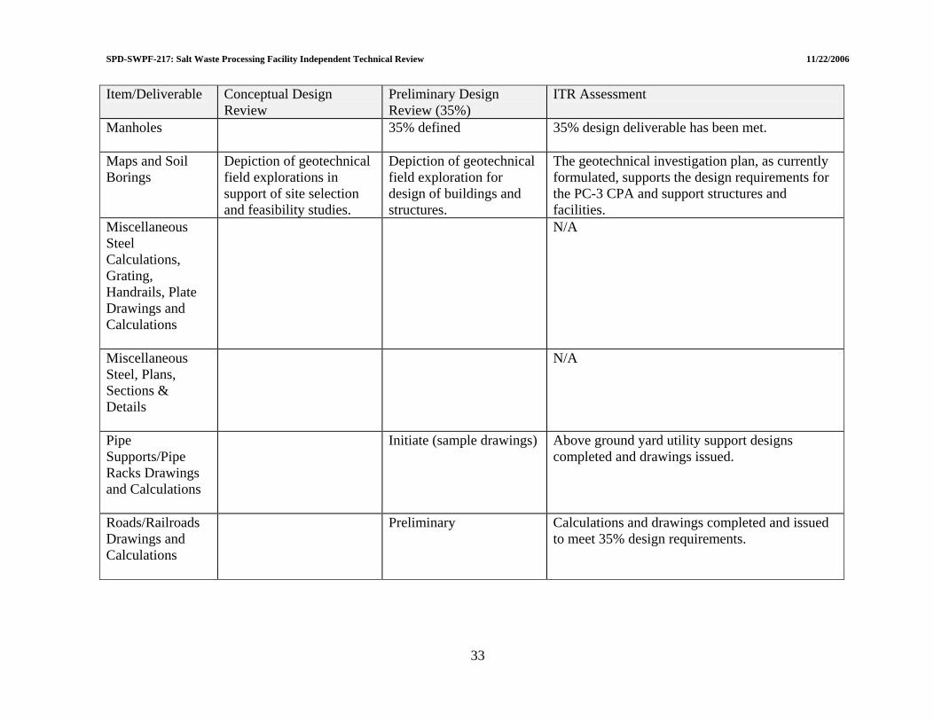
SPD-SWPF-217: Salt Waste Processing Facility Independent Technical Review 11/22/2006
Item/Deliverable Conceptual Design Review
Preliminary Design ITR Assessment Review (35%)
Manholes
35% defined 35% design deliverable has been met.
Maps and Soil Borings
Depiction of geotechnical field explorations in support of site selection and feasibility studies.
Depiction of geotechnical field exploration for design of buildings and structures.
The geotechnical investigation plan, as currently formulated, supports the design requirements for the PC-3 CPA and support structures and facilities.
Miscellaneous Steel Calculations, Grating, Handrails, Plate Drawings and Calculations
N/A
Miscellaneous Steel, Plans, Sections & Details
N/A
Pipe Supports/Pipe Racks Drawings and Calculations
Initiate (sample drawings) Above ground yard utility support designs completed and drawings issued.
Roads/Railroads Drawings and Calculations
Preliminary Calculations and drawings completed and issued to meet 35% design requirements.
33

SPD-SWPF-217: Salt Waste Processing Facility Independent Technical Review 11/22/2006
Item/Deliverable Conceptual Design Review
Preliminary Design ITR Assessment Review (35%)
Sanitary/Storm Sewers Drawings and Calculations
Preliminary Calculations and drawings completed for sanitary and storm (during construction and post construction) sewer design.
Seismic Analysis
Prepare preliminary calculations
Analysis results of the preliminary seismic calculations were reviewed which resulted in several analysis/design recommendations.
Settling Basins
Preliminary Calculations completed and drawings issued to meet 35% design deliverables.
Sheet Piling & Dewatering
N/A
Shoring Drawings and Calculations
N/A
Site and Plot Plans
Overall layout of buildings, roads, access roads, railroad and utility connections for project validation at CDR.
Refine to allow preparation of civil site contracts and issue long lead permit applications.
Site plot plan and site utility interface plot plan have been issued.
Soils and Earth Pressure Calculations
N/A
Structural Concrete Plans and Calculations
Conceptual documents with adequate detail to develop Project Baseline Estimate and CDR.
Develop documents to support specifications and contract for structural concrete.
Analysis, design, drawings and specifications issued to meet 35% design level.
34

SPD-SWPF-217: Salt Waste Processing Facility Independent Technical Review 11/22/2006
Item/Deliverable Conceptual Design Review
Preliminary Design ITR Assessment Review (35%)
Structural Concrete Sections & Details and Calculations
Develop documents with sufficient detail for completion of structural concrete procurement and installation specifications.
Structural calculations completed and specifications issued to meet 35% design requirements.
Structural Specifications
Prepare structural data sheets for applicable facilities and include within contract packages.
Eight specifications issued to support contract packages for concrete and structural steel.
Structural Specifications
Prepare specifications for the procurement and installation of buildings, structures and components.
Pre-engineered and modular building specifications are found in the Architectural specifications. Components are addressed in other discipline specifications such as electrical, mechanical and HVAC.
Structural Steel Drawings and Calculations
Conceptual documents with adequate detail to develop Project Baseline Estimate and CDR.
Develop documents to support specifications and contract for structural steel.
Analysis and design completed to support development of specifications and structural steel procurement.
Tray and Conduit Supports Drawings and Calculations
N/A
Yard Utilities Drawings and Calculations
Preliminary Completed and issued to meet 35% design requirements.
35

SPD-SWPF-217: Salt Waste Processing Facility Independent Technical Review 11/22/2006
36
Item/Deliverable Conceptual Design Review
Preliminary Design Review (35%)
ITR Assessment
Master Plan
Combine site selection studies, facility relationship diagrams, site arrangement concept studies, site access and egress studies into one comprehensive master plan.
Update as needed No update required given that the Site Plot Plans and the Civil drawings (roads/utilities/transfer line drawings) contain the necessary detailed information and that the overall Site location with the SRS has not changed.
Primary / Alternate Site Selection
Complete to support conceptual design.
N/A
Site Selection Studies
Preliminary characterization and site selection
Final characterization and site selection
Geotechnical field and laboratory testing is ongoing. The results could agree with prior perceptions of geotechnical conditions, but they could also raise new site characterization issues that will have to be addressed.
SPD-SWPF-217: Salt Waste Processing Facility Independent Technical Review 11/22/2006
4.0 FACILITY SAFETY 4.1 RADIATION PROTECTION To evaluate the adequacy of radiation protection defined in the preliminary design, it is necessary to understand the DOE's expectation for preliminary design. The following guidance is taken from the DOE project management directive:
Preliminary Design: Preliminary design is complete when it provides sufficient information for development of the Performance Baseline in support of CD-2. (DOE O 413.3A, Section 5.d.(3)) Performance Baseline: The Performance Baseline… defines the cost, schedule, performance, and scope… where the requirements and design are mature and the uncertainty and risks have been eliminated, reduced, mitigated, or accepted…. (DOE O 413.3A, Section 5.k.(8))
From this directive, it is clear that the preliminary design must be mature enough to define the cost, schedule, performance, and scope of the project. Obviously, the more complete the design, the better the understanding of these key parameters. This review of the radiation protection defined in the preliminary design is intended to determine if it is adequately mature. In addition, the DOE directs that the uncertainty and risks have been eliminated, reduced (presumably to an acceptable level), mitigated, or accepted in the preliminary design. The risks to the public, co-located onsite workers and facility workers must be addressed for both postulated accidents and routine operations. The Preliminary Hazards Analysis[1] has been developed and was updated by the Hazard and Operability Review (HAZOP)[2] and the Hazard and Operability 2 Review Summary Report[3] to be consistent with the Enhanced Preliminary Design and associated identified hazards, and the Preliminary Documented Safety Analysis[4] (PDSA) has been developed to define the controls necessary to eliminate or mitigate the risks. The PDSA also addresses routine operations. Addressing these risks reduces the potential for unacceptable risks as the facility is designed, built, commissioned, operated, and ultimately decommissioned and demolished. The DOE Work Safety and Health Program rule [10 Code of Federal Regulation (CFR) 851] was published on February 9, 2006[5], and requires submission of a written program.
§ 851.11 Development and approval of the worker safety and health program. (a) Preparation and submission of worker safety and health program. By February 26, 2007, contractors must submit to the appropriate Head of DOE Field Element for approval a written worker safety and health program that provides the methods for implementing the requirements of Subpart C of this part.
37

SPD-SWPF-217: Salt Waste Processing Facility Independent Technical Review 11/22/2006
This program document is in concurrent EPC interdisciplinary document review and informal DOE draft review. The stated goal is to formally submit the document to DOE in early December 2006. For this review, DOE and the EPC identified specific radiation protection documents[6-12] for evaluation. Each of these documents is addressed later in this section. Findings of the review of Radiation Protection are summarized in Table 4-1. 4.1.1 Confinement Radioactive material confinement includes both the prevention of contamination within the facility during normal operations and upset conditions, and containment of the material within the structure during normal operations and under accident conditions. Confinement, as discussed here, provides protection to the facility, co-located worker, offsite public, and the environment. The confinement of radioactive material sufficient to meet project and regulatory requirements is analyzed in Chapter 3 of the PDSA. This analysis is addressed in general in Section 4.3.1.2 of this report and confinement details are addressed below. 4.1.1.1 Summary of response to LOI II.a.1 “Do the tanks, piping, structure provide sufficient confinement of radiological material consistent with PC-3 requirements?” The preliminary design intent is to contain all radioactive material within the vessels, pipes, pumps, and valves resulting in no release into or outside of the facility. The design does include seismic criteria against which to evaluate Performance Category 3 (PC-3). These criteria are applied to tanks, piping, and structure to prevent failure resulting in release of radioactive material into the facility. As addressed in Section 5.2 of this report, the criteria are appropriately applied with the exceptions noted in that section. With respect to radiological control through containment, the preliminary design is adequate. The facility structure is designed to withstand Natural Phenomena Hazard events and maintain confinement. This provides sufficient confinement of radioactive material, preventing release to the environment. Review of this confinement is provided in Section 5.3 of this report.
38
SPD-SWPF-217: Salt Waste Processing Facility Independent Technical Review 11/22/2006
4.1.1.2 Consistent with PC-3 requirements To validate that confinement is consistent with PC-3 requirements, it is necessary to review these requirements:
Performance Category 3: An SSC shall be placed in preliminary Performance Category 3 (PC-3)… if its failure during an NPH event could result in off-site release consequences greater than or equal to the unmitigated release from a large (>200 MWt) Category A reactor severe accident), and if: its failure results in adverse release consequences greater than safety class SSC Evaluation Guidelines limits but much less than those associated with PC-4 SSCs. (DOE-STD-1021)
To the extent possible in preliminary design, Chapter 3 of the PDSA has systematically identified potential accidents and analyzed their consequences to offsite, onsite (outside the facility), and onsite (inside the facility). In some cases administrative and design features must be credited with mitigating the accident consequences to adequate levels. These mitigative features are identified as requiring performance categorization sufficient to continue operation under those accident conditions. Thus, radiological control is assured under PC-3 conditions when necessary. Re-evaluation and updating of the results of this process after final design will be necessary to ensure meeting radiological impact criteria under accident conditions. 4.1.1.3 Filter loading uncertainty The preliminary design provides for High-Efficiency Particulate Air (HEPA) filter [Process Building Ventilation System (PBVS) and Process Vessel Vent System (PVVS)/Process Mixer Vent System (PMVS)] removal using direct contact (hands-on) changing and transport using the installed monorail system out of the vent room (located on Level 139’). At that point the filters are loaded onto a hand operated transport cart for movement within the building[13]. The preliminary design does not currently estimate the rate of filter loading; thus it is not possible to predict the frequency required for filter change. It may not be consistent with ALARA goals to perform these filter changes and transport using direct contact methods. Evaluation of alternatives should be considered. 4.1.1.4 Nuclear criticality The Nuclear Criticality Safety Evaluation[14] (NCSE) was reviewed to assure that inadvertent criticality has been adequately analyzed. The subcritical mass limits of the applicable ANSI/ANS standard[15] are not exceeded in the Sludge Solids Receipt Tank even if 26 batches of alpha sorption process solids are collected in the tank. The process is designed to accumulate no more than five batches. It is not credible that this quantity of fissile material could be collected in the tank, thus criticality is not a concern at this location. Several other potential criticalities are addressed in this document as well. Bounding fissile masses from the SWPF Project Safety Analysis Mass Balance Run[16] were used for the analysis. Sampling and analysis to assure incoming waste meets the SWPF WAC is one administrative
39

SPD-SWPF-217: Salt Waste Processing Facility Independent Technical Review 11/22/2006
control to assure that concentrations in excess of those analyzed are not accepted by the facility. Change control is necessary to assure that the facility equipment and processes credited in the NCSE are maintained. Nuclear Criticality Safety has been addressed from a process perspective in Section 5.1.1.3.5. 4.1.1.5 Laboratory design The SWPF analytical laboratory design was reviewed with respect to radiological control. A standard glovebox, radiological hood, and laboratory bench design is used throughout the laboratory. Analytical equipment to be used is described as “bench top” design and does not require any custom glovebox design. Laboratory sample concentrations have been evaluated against Savannah River Site criteria[17] to determine the appropriate containment location for handling. Positive Finding 4.1-1: The SWPF laboratory preliminary design is well developed for anticipated sample nature and load. There is a concern that the preliminary design of the laboratory hot cell liner is not optimum for D&D. This has been addressed in Section 5.7. 4.1.1.6 De-inventory and wash process The success of cross-flow filter cleaning (SWPF Process Basis of Design, P-DB-J-00003, Rev. 0, Section 3.1.7) immediately before filter change is not well understood. Current plans are to backwash the cross-flow process filters prior to removal. It is not known at what level contamination will remain on the filters following backwash. The amount of shielding required to keep worker exposures ALARA is not known. The EPC Environmental, Safety, Health, and Quality (ESH&Q) Organization should define research needs for incorporation into the test plans for CSSX and AST testing related to these issues. Information could be collected from these tests that would help the EPC ESH&Q Organization understand the dose rates to be expected, and will provide input to the final ALARA design. The use of draining and flushing is discussed as a key ALARA element in SWPF system maintenance. It is not clear how successful these steps will be reducing the dose rates to appropriate levels (Preliminary ALARA Design Review Report, Section 3.1). A combination of solid deposits and internal film on piping and vessel interior surfaces may result in unacceptable dose rates. For example, the Mass Balance Model Summary Description[17]
shows solids from waste Tank 37H that the reviewer determined can produce 8.3 mR/hr per gram at 1 foot (1/4 from Co-60 and 3/4 from Cs-137). Although there has been some discussion within the EPC ESH&Q Organization of evaluating this potential during stimulant and real waste testing, nothing formal has been documented in the test plans. Area of Concern 4.1-11: Test plans do not include collection of data necessary to estimate post-flushing dose rates.
40
SPD-SWPF-217: Salt Waste Processing Facility Independent Technical Review 11/22/2006
Recommendation AC 4.1-11: Test plans should be updated to provide information relevant to anticipated holdup in SWPF systems and the effectiveness of system flushing. 4.1.1.7 10 CFR 835 Implementation The DOE Radiation Protection rule (10 CFR 835)[19] is applicable to this project and requires radiological controls necessary for safe operation. During the design process, the design-relevant portion of Part 835 must be implemented. This has been addressed in the SWPF Radiation Protection Plan[7] developed for design and construction. The portion of Part 835 that is applicable to design is Subpart K, “Design and Control.” 4.1.1.7.1 ALARA design ALARA design requirements for external exposure control, containment, decontamination, and internal exposure control have been identified by the EPC ESH&Q Organization and documented in the ALARA Review procedure PP-RP-4501[20]. These design requirements implement some of the requirements in Part 835, Subpart K. Discussion with the ES&HQ manager indicates that these requirements are applied during the interdisciplinary review process and transmitted to the design organization as necessary. The responsibility of the design organization to use these requirements is not supported by the responsibilities section of this procedure. It is necessary that these requirements be incorporated into the design criteria for implementation during the design process. Requirements of concern from the ALARA Review procedure include:
• Radiological Containment Requirements (PP-RP-4501, Table 6-2)
– Provide secondary containment for transfer lines and appurtenance (e.g., flanges, valves, pumps, filters, strainers, etc.), with leak detection for alarm and pump shutdown interlocks
• Radiological Decontamination Requirements (PP-RP-4501, Table 6-3)
– Facility design shall keep service piping, conduits, and ductwork to a minimum in
areas that could be potentially contaminated and, if included in such areas, it is designed to facilitate decontamination.
– Facility Design shall minimize cracks, crevices, and joints to prevent
accumulation of contaminated material.
– Consider finishing walls, ceiling, and floors in areas vulnerable to contamination with washable or strippable coverings.
– In laboratories, seamless counter top and floor coatings should be used and, when
it cannot be used, the surface coating shall provide for physical sealants to be applied at all seams.
41

SPD-SWPF-217: Salt Waste Processing Facility Independent Technical Review 11/22/2006
– The design shall provide for flushing and/or cleaning contaminated or potentially
contaminated piping systems.
– The design shall maximize the use of removable covers for inspection and cleanouts for tanks and vessels.
• Internal Radiation Exposure Requirements (PP-RP-4501, Table 6-4)
– Incorporate design features to prevent the buildup and spread of contamination.
Minimize surface from which radioactive material can be suspended. Ensure that facility layout and system design provide for ease of decontamination.
Area of Concern 4.1-12: The ALARA design requirements identified in PP-RP-4501 are not specifically implemented as project design criteria. Recommendation AC 4.1-12: Promulgate ALARA design requirements as project design criteria such that these are implemented by the design organization in the final design. Also, see Section 5.1.1.2.6, Suggested Improvement 5.1-22. 4.1.1.7.2 Physical design features The preliminary design for SWPF relies primarily on containment and shielding to minimize worker exposure. Dose rates consistent with project design criteria are achieved in most locations and those locations above these levels are under development to attain these levels. Little reliance on administrative design features was observed. As is prudent for radiological design, the potential for airborne radioactive material release has been recognized and monitoring placed accordingly. 4.1.1.7.3 Optimization methods used 10 CFR 835.1002(a) states that optimization methods shall be used. Optimization methodology is addressed the DOE Implementation Guide for ALARA:
At sites with significant collective dose, formally documented optimization methodologies should be developed for ALARA reviews and decisions on implementation of ALARA efforts should be developed. … The level of effort involved in documenting ALARA decisions should be commensurate with the potential dose savings to be realized. (DOE G 441.1-2)
The ALARA Review procedure (PP-RP-4501) does address optimization, but no evidence of its application was observed. Although ALARA optimization is a routine thought process for professional Health Physicists, the application of a formalized process is appropriate in some portions of the design process. An additional reference for this process is the somewhat
42

SPD-SWPF-217: Salt Waste Processing Facility Independent Technical Review 11/22/2006
older, Health Physics Manual of Good Practices for Reducing Radiation Exposure to Levels that are As Low As Reasonably Achievable (ALARA), PNL-6577, located at www.pnl.gov/bayesian/refs/classics.htm (last accessed on October 13, 2006). Suggested Improvement 4.1-3: It is suggested that the radiological optimization process be more formally applied in the Final Design. 4.1.1.7.4 Avoid airborne radioactive material With respect to airborne contamination, 10 CFR 835.1002(c) requires,
“…the design objective shall be, under normal conditions, to avoid releases to the workplace atmosphere….”
It appears that the ALARA Review procedure requirements for internal exposure (PP-RP-4501, Table 6-4) are inconsistent with this approach, allowing up to 10% of the Derived Air Concentration. The Rule is somewhat vague with respect to this and goes on to state,
“…and in any situation, to control the inhalation of such material by workers to levels that are ALARA….”
Area of Concern 4.1-13: The ALARA design requirement for airborne contamination in the workplace is inconsistent with 10 CFR 835.1002(c) in that it allows up to 10% of the Derived Air Concentration in occupied operating areas during normal operating conditions. Recommendation: AC 4.1-13: The SWPF design requirement for airborne contamination should address compliance with the 10 CFR Part 835 requirement. 4.1.2 Bulk Wall Shielding 4.1.2.1 Summary of response to LOI II.a.2 “Are the concrete walls of sufficient thickness to meet 10 CFR 835 requirements?” The review addressed the following subjects for this LOI:
• Bulk Wall Shielding Analysis Capability • Bulk Shielding Analysis Calculations • Shielding Design Confirmation • Interaction with Design • Shielding Analysis Quality Assurance
The review for each of these subject areas are described below. It is concluded that the methods, approach, and results for bulk wall shielding design is very good. The design will be able to achieve 0.5 millirem per hour (mR/hr) or less for continuously occupied areas.
43

SPD-SWPF-217: Salt Waste Processing Facility Independent Technical Review 11/22/2006
It is further concluded that there is a comprehensive and complete approach to integrating the shielding analysis with design and with the projected operations and maintenance activities. 4.1.2.2 Bulk wall shielding analysis capability The EPC ESH&Q Organization’s capability was reviewed with regard to the software and users for analyzing shielding design, as follows:
• The primary tool for evaluation of shielding and placement of equipment that contains sources is the MicroShield® software. MicroShield® is a robust tool that has been used worldwide for this type of application for design and operations. It uses the point-kernel method and was developed with data from the Radiation Shielding Information Center at Oak Ridge, Tennessee that is embodied in ANS 6.4.3. It is an excellent choice for much of the analyses and calculations that are needed to conform the SWPF design to 10 CFR 835.
• The lead analyst applying the software has an excellent depth of experience, having
used MicroShield® for past projects. Discussions indicated a good understanding of the principles and application of shielding analysis.
It is concluded that the capability for shielding analysis is very good. Positive Finding 4.1-2: The EPC ESH&Q Organization’s capability was reviewed with regard to the software and users for analyzing shielding design. MicroShield® is an excellent choice for much of the analyses and calculations that are needed to conform the SWPF design to 10 CFR 835. The lead analyst applying the software has an excellent depth of experience, having used MicroShield® for past projects. 4.1.2.3 Bulk wall shielding analysis calculations Shielding calculations were reviewed and an independent calculation was conducted, as follows:
• The EPC analyst’s sample calculations were reviewed and found to be appropriate for the purpose. Two observations resulting from the use of MicroShield® are worth noting:
– Using air as a buildup factor reference material instead of concrete or steel leads
to a very conservative over-prediction of dose rates by as much as 60%. (The reasons for this are subtle and are not explained here.)
– Using the grouping method that represents the gamma energy as 0.6 million
electron volts (MeV), versus the actual gamma energy of 0.662 MeV, will under-predict the dose rate.
44

SPD-SWPF-217: Salt Waste Processing Facility Independent Technical Review 11/22/2006
The net effect of this approach is a dose rate prediction that is conservatively high, especially when combined with the assumption of a maximum source concentration of 86 curies (Ci) per gallon (Ci/gal), which is higher than will be the case during facility operation. A preferred approach would be to use the actual shield material as the buildup reference and the actual gamma energy. In borderline cases where small variations in shielding create results close to the dose rate limits, conservatism can be added with a safety factor.
• An independent, simplified scoping calculation was conducted by the reviewer to
gain perspective on the shielding thickness needed for cesium sources of the magnitude anticipated within the SWPF. This was done by modeling a disk source of water that is 10 ft thick with a 50 ft radius to simulate a planar field imposed upon a concrete wall. The concentration used was 86 Ci per gallon, which is the safety basis maximum concentration. The resulting dose rate along the axis on contact with the concrete shield is shown in the following graph (Figure 4-1). This indicates that, in general, a concrete wall thickness of 3 to 4 ft will result in a dose rates less than 0.5 mR/hr. This leads to the conclusion that the bulk wall thickness in the SWPF design is sufficient.
0.001
0.01
0.1
1
10
100
1000
10000
100000
0 1 2 3 4 5
Concrete Thickness, Ft
Dose
, mR/
hr
Figure 4-1. Dose Rate with Concrete Shielding for 86 Ci/gal Infinite Source
The EPC shielding calculations results in dose rate predictions that are conservatively high; that is, in some cases they can create a need for more shielding than is necessary. This may not matter with regard to the design as bulk shielding thickness is not usually “fine-tuned” to dose calculations as long as it is sufficient.
45
SPD-SWPF-217: Salt Waste Processing Facility Independent Technical Review 11/22/2006
Suggested Improvement 4.1-4: It is suggested that the preferred approach is to use the shielding software in a manner that most realistically represents the physical conditions. Then, for borderline cases of calculated shield thickness, a safety factor should be then added to the analytical result to make sure the shield is sufficient. Positive Finding 4.1-3: Shielding calculations were reviewed and an independent calculation was conducted. The bulk wall thickness in the SWPF design was verified to be sufficient. 4.1.2.4 Shielding design confirmation Table 6-1 of Operations Requirements Document (P-ESR-J-00011) summarizes the tests to be conducted for the facility. There is no mention of shield verification during hot or cold testing. The reviewers were informed verbally by the EPC ESH&Q Organization that they plan to conduct such verification, with sources during cold testing, and by surveys during hot startup. There is no written commitment to a formal test procedure to confirm the radiation shielding in areas where low dose rates must be achieved prior to and during initial operations. A commitment to such a procedure should be documented. Suggested Improvement 4.1-5: It is suggested that the EPC commit to a formal test procedure to confirm the radiation shielding in areas where low dose rates must be achieved prior to and during initial operations. 4.1.2.5 Interaction with design Interaction between the EPC ESH&Q Organization and the EPC Design Group was reviewed via:
• A punch list (Reference No. 00-700-03488, File 3.5.1) of issues that contained recommendations and resolutions. This list was detailed and relevant, indicating a comprehensive interaction between the two organizations.
• Meeting minutes (Reference No. 02-700-00416, File 3.2.40) with resulting actions addressing the CSSX Pump and Valve Gallery and re-arrangement of equipment and shielding configuration.
• Results of pipe re-arrangement that would lower the dose rate for maintenance personnel.
It is concluded that interaction between the shielding analysts and designers is very good.
46

SPD-SWPF-217: Salt Waste Processing Facility Independent Technical Review 11/22/2006
Positive Finding 4.1-4: Interaction between the EPC ESH&Q Organization and the EPC Design Group was found to be excellent with evidence of design modifications that were made to reduce dose rates. 4.1.2.6 Shielding analysis quality assurance Quality Assurance for shielding analysis was reviewed by:
• Noting that the MicroShield® verification and validation (V&V) package has been procured along with the code and used for V&V.
• Preliminary ALARA Design Review Report (S-EIP-J-00004) contains a description
of the use of MicroShield® for the project.
• 100% of the calculations are reviewed.
• MCNP is Monte-Carlo method software that is diverse from MicroShield®. It will be used to confirm selected MicroShield® results. It will also be used for labyrinth calculations, which MicroShield® cannot do.
It is concluded that the Quality Assurance for shielding analysis is very good. Positive Finding 4.1-5: Quality Assurance for shielding analysis is excellent based upon the use of the MicroShield® verification and validation package, 100% of the calculations are reviewed, and MCNP (Monte-Carlo method) software will be used to confirm selected MicroShield® results. 4.1.3 Radiation Scatter Through Penetrators, Pump, and Valve Gallery Labyrinths 4.1.3.1 Summary of response to LOI II.a.3 “Are the penetrations and galleries adequately designed to meet 10 CFR 835 requirements?” The review addressed the following subjects for this LOI:
• Labyrinth Entrances • Penetrations • Skyshine
The review for each of these subject areas are described below. It is too early in the design to review results of analysis and resulting design configurations. However, it is concluded that the planned methods and the available capability are sufficient to address streaming and scattered radiation.
47

SPD-SWPF-217: Salt Waste Processing Facility Independent Technical Review 11/22/2006
4.1.3.2 Labyrinth entrances Preliminary estimates have been completed for labyrinth entrances and based on those estimates, location of piping and other components within the pump rooms are being revised. A task has been initiated by a group in Pasco, Washington (where the code and its users are qualified) to calculate labyrinth entrance doses using the MCNP Monte-Carlo code. The specification for the calculations to be conducted includes direct dose as well as scattered dose through the labyrinth and a correlation of dose outside the labyrinth to that impinging on the interior opening. The results will be useful for establishing a calculation method for all labyrinths in the facility. These labyrinth calculations can be compared with results obtained by the method described in: Peng, W, Application of the Albedo Method to Calculate the Dose Rate from Scattered Gamma-Rays in a Labyrinth, presented at the Health Physics Society 1988 Meeting, TP 88-52, July 4-8, 1988. Based on very preliminary review using this reference, it appears that the dose rates outside of the labyrinth entrances will be in the range of 0.5% to 3% of the impinged radiation at the labyrinth entry into the high radiation area. It has been observed that the EPC ESH&Q Organization and the EPC Design Group have given much attention to the placement of equipment within rooms to reduce dose rates outside of labyrinths. Suggested Improvement 4.1-6: Preliminary dose estimates have been conducted for labyrinth entrances and based on those results, location of piping and other components within the pump rooms are being revised. A task has been initiated to calculate labyrinth entrance doses using the MCNP Monte-Carlo code. It is suggested that an independent technical review of the labyrinths calculations and design when their design is close to being finalized. 4.1.3.3 Penetrations It is too early in the design to review the results of calculations for penetrations. However, the expertise is available within the EPC Organization to conduct such calculations using MCNP. At present, the local version of MCNP is not formally qualified and thus current calculations are for screening purposes. Suggested Improvement 4.1-7: It is suggested that MCNP be formally qualified locally for later use when penetration designs are being finalized. 4.1.3.4 Skyshine Section 16.3.3.1 of Operations Requirements Document (P-ESR-J-00011) states that “Structural configurations shall be reviewed to determine the effect on the design radiation levels including consideration given to Skyshine….”
48
SPD-SWPF-217: Salt Waste Processing Facility Independent Technical Review 11/22/2006
49
EPC indicated that no Skyshine calculations are planned because the site boundary is 11 miles away. Independent calculation with an extremely conservatively high source term indicates that the sky scattered dose is trivial as close as 1,000 feet distance. The ITR concurs with the conclusion that documented calculations are not necessary. 4.1.4 Risk Management Few preliminary design project risks are radiation protection related. Those that are significant relate to the maintenance-related worker exposure. 4.1.4.1 Summary of response to LOI II.a.4(i) “Have all radiation protection risks been identified and addressed; do any remain?” The EPC ESH&Q Organization had identified most of the radiological risks to the level appropriate for preliminary design and has efforts underway to understand and mitigate these risks. However, the ITR Team has a concern that the “de-inventory, flush, then hands-on maintenance” approach may result in unacceptable maintenance worker exposure. It is important that the SWPF project gain as much information from facilities with similar materials to better understand this issue. Area of Concern 4.1-14: The SWPF project does not appear to have used maintenance experience at facilities (both onsite and offsite) to help understand the maintenance worker dose that will be experienced at the plant. Recommendation AC 4.1-14: Complete an effort to identify, collect, and utilize information from facilities with similar materials to estimate the maintenance worker dose anticipated for the SWPF during the operational period of the facility. 4.1.4.2 Summary of response to LOI II.a.4(ii) “Have risks resulting from the conversion from ISO-9001 to NQA-1 been adequately addressed?” Conversion from ISO-9001 to NQA-1 is anticipated to have little effect on Radiation Protection at this point in the project. The EPC ESH&Q Organization is not responsible for design, nor has it initiated any procurement activities on the SWPF project. Thus, it is unlikely to have any significant issues associated with implementing NQA-1. This organization does provide shielding design and has utilized the MicroShield® code for this purpose. They have obtained the V&V package for the code and state that they are meeting the project software certification requirements.
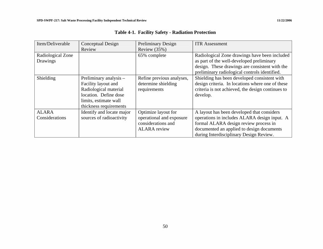
SPD-SWPF-217: Salt Waste Processing Facility Independent Technical Review 11/22/2006
50
Table 4-1. Facility Safety - Radiation Protection Item/Deliverable Conceptual Design
Review Preliminary Design Review (35%)
ITR Assessment
Radiological Zone Drawings
65% complete Radiological Zone drawings have been included as part of the well-developed preliminary design. These drawings are consistent with the preliminary radiological controls identified.
Shielding
Preliminary analysis – Facility layout and Radiological material location. Define dose limits, estimate wall thickness requirements
Refine previous analyses, determine shielding requirements
Shielding has been developed consistent with design criteria. In locations where one of these criteria is not achieved, the design continues to develop.
ALARA Considerations
Identify and locate major sources of radioactivity
Optimize layout for operational and exposure considerations and ALARA review
A layout has been developed that considers operations in includes ALARA design input. A formal ALARA design review process in documented an applied to design documents during Interdisciplinary Design Review.

SPD-SWPF-217: Salt Waste Processing Facility Independent Technical Review 11/22/2006
4.2 MATERIAL HANDLING 4.2.1 Overhead Cranes/Hoists 4.2.1.1 Summary of response to LOI II.b.1 “Does the planned operating envelop safely support radiation/contamination controls, maintenance and operation of all components?” The CD-2 design document deliverables for the Overhead Cranes/Hoists have in place the base material handling equipment for the handling of the process equipment and accessories to support operation/maintenance activities. It is apparent that a “hands-on” approach will be used for removal/replacement and maintaining the process equipment. In some cases, this “hands-on” approach is quite extensive. For the ASP Filter Tubesheets, there are eighteen (18) separate activities[21] associated with the removal from service to staging for transportation to the Material Storage and Staging Area. On this basis, to achieve ALARA goals, it is critical that radiological and administrative controls be adequate and followed, specifically in the high radiation areas that will be downgraded for the material handling activities. It is also critical that the decontamination process is adequate for the equipment components to be handled for removal. Without adequate and achievable controls and decontamination methods, in conjunction with process equipment module design features, the consistent achievement of ALARA goals will be problematic. 4.2.1.2 Operating envelop assessment 4.2.1.2.1 Bridge Crane - Operating Deck, Capacity: 20/7.5/1 Ton Hoists The bridge crane accesses the operating deck at elevation 139'-0". Crane/bridge travel is East/West between coordinates/column lines 1 and 11 and North/South between coordinates/column lines E.2 and F.5.[22] The crane bridge mounted hoisting trolley travel is North/South. The total hook/lift is 70'-0" from a high hook elevation of 168'-6".[23] The overall operating envelop is considered functional for the Operating Deck at elevation 139'-0" to below the Operating Deck at elevation 98'-6". The locations of the Closed-Circuit Televisions (CCTVs) are not evident at this stage of design development. Therefore it cannot be determined if the CCTVs are within the crane operating envelop.[24] The final overall operating envelop of the crane and the hoists may be smaller than noted above, based on the final crane bridge/trolley design that encompasses inherent travel limiting factors such as hoist trolley size and mounting location, and size/length of the crane bridge end trucks. These limiting factors should be reviewed in subsequent design activities to assure the crane/hoists can perform the following tasks as a minimum:
• Remove and Install Cell Cover Blocks • Remove and Install Filter Access Plugs • Remove and Install Cross-Filter with Cask • Remove and Install CCTVs
51

SPD-SWPF-217: Salt Waste Processing Facility Independent Technical Review 11/22/2006
• Remove and Install Valve Operators 4.2.1.2.2 Bridge Crane - Hot Cell, Capacity: 1/2 Ton The bridge crane accesses the Hot Cell located in the Laboratory Area between coordinates/column lines F.5, J, 1.5 and 3.9.[25] The crane bridge travel is East/West within the Hot Cell. The crane bridge mounted hoist/trolley travel is North/South. The total hook/lift from the Hot Cell floor elevation of 141'-8" is not specified. The overall operating envelop[26] of the bridge crane is considered functional within the Hot Cell, excluding the unstated hoisting hook range. The final overall operating envelop of the crane and hoist may be smaller than noted above, based on the final bridge/trolley design that encompasses inherent travel limiting factors such as hoist trolley size and mounting location, and size/length of the crane bridge end trucks. These limiting factors should be reviewed in subsequent design activities to ensure the crane/hoist can perform the required tasks. The required tasks are not stated within this stage of design development. Suggested Improvement 4.2-8: Equipment and equipment locations have not been determined within the Hot Cell. Therefore, the planned operating envelop of the Hot Cell crane cannot be confirmed relative to operations and maintenance support of the in-cell equipment. Crane operating envelop with respect to in-cell equipment should be addressed in future design activities. 4.2.1.2.3 Bridge Crane – AFF, Capacity: 5 Ton The bridge crane accesses the AFF Area between coordinates/column lines K, L, 7.3 and 14.[27] The crane bridge travel is East/West. The crane bridge mounted hoisting trolley travel is North/South. The total hook/lift from the AFF floor is 33'-0". The overall operating envelop within the AFF area is considered functional, excluding the hoist hook upper lifting range (Section 4.2.1.3). The final overall operating envelop of the crane and the hoist may be smaller than noted above, based on the final crane bridge/trolley design that encompasses inherent travel limiting factors such as hoist trolley size and mounting location, and size/length of the crane bridge end trucks. These limiting factors should be reviewed in subsequent design activities to assure the crane/hoist can perform the following tasks as a minimum:
• Remove and Install Pumps and Motors • Remove and Install AFF Filters • Remove and Install Agitators
4.2.1.3 Equipment accessibility/maintenance assessment 4.2.1.3.1 Bridge Crane - Operating Deck, Capacity: 20/7.5/1 Ton Hoists The equipment items to be removed, replaced and serviced, excluding the CCTVs, are within the present operating envelop of the bridge crane/hoists, pending the final crane/hoist operating envelop final crane design variables as noted in Section 4.2.1.2.1. The Cell Cover
52
SPD-SWPF-217: Salt Waste Processing Facility Independent Technical Review 11/22/2006
Blocks, Filter Access Plugs and Valve Operators are located on the Operating Deck. The AFF Cross-Flow filters are located/mounted directly to the Operating Deck, extending below the deck floor and are accessed via the Filter Access Plug locations. Estimated unit weights of equipment to be serviced, other than the ASP Filters/Cask weights,[28] are not evident; therefore crane/hoists design capacities could not be confirmed. Area of Concern 4.2-15: The accessibility of the bridge crane for maintenance is via a maintenance platform located at the East end of the Operating Deck. The method/equipment required for removing/lowering/lifting failed and replacement crane components from/to the maintenance platform is not evident within this stage of design document deliverables. Recommendation AC 4.2-15: Install wall mounted jib crane(s) for lowering and hoisting bridge crane components. This is specific to the Operating Deck and AFF Bridge Cranes. 4.2.1.3.2 Bridge Crane - Hot Cell, Capacity: 1/2 Ton The equipment items to be removed, replaced and serviced within the Hot Cell, including locations are not defined at this stage of design. The bridge crane travel envelop is functional, pending the final crane/hoist operating envelop design variables as noted in Section 4.2.1.2.2. Equipment accessibility within the Hot Cell cannot be determined. Without data regarding equipment to be supported within the Hot Cell, crane/hoist design capacity could not be confirmed. The accessibility of the bridge crane/hoist within the cell and method of maintenance and removal of failed components is not defined at this stage of design document deliverables. Suggested Improvement 4.2-9: Bridge crane design capacities are given without reference data for estimated weights of hoisted equipment/components. This should be addressed prior to equipment specification and procurement activities. 4.2.1.3.3 Bridge Crane – AFF, Capacity: 5 Ton The equipment items to be removed, replaced and serviced within the AFF are considered accessible within the stated crane travel envelop, pending the final crane/hoist operating envelop design variables as noted in Section 4.2.1.2.3. Although the equipment is considered assessable, the total available hoisting lift (33'-0") of the 5-ton hook may not be adequate to remove the agitator assembly from the process vessel(s) in a one (1) piece assembly. Process vessel elevations, with mounted agitators, are not identified at this stage of design/document deliverables. The weights of equipment to be serviced within the AFF are not defined, so the design capacity of the crane/hoist could not be confirmed. The method/equipment required for accessing/removing/lowering/lifting failed and replacement crane components is not defined at this stage of design document deliverables. Area of Concern 4.2-16: Adequate head room/crane hoist lifting range is not evident in the AFF Area for removal/replacement of the process vessel mounted agitators.
53

SPD-SWPF-217: Salt Waste Processing Facility Independent Technical Review 11/22/2006
Recommendation AC 4.2-16: Determine headroom required to remove agitator(s) assemblies from the process vessel(s). Adjust crane hoist lift height and/or agitator mounting height so to remove from process vessel(s) in one assembly. 4.2.2 Equipment Monorails/Carts 4.2.2.1 Summary of response to LOI II.b.2 “Does the planned operating envelop safely support maintenance and operation of all components?” The CD-2 design document deliverables for the Monorails/Carts have in place the base material handling equipment nucleus for the handling of the process equipment and accessories to support operation/maintenance activities. From a safety aspect, it is apparent that a “hands-on” approach will be used for removal/replacement and maintaining the process equipment. On this basis, to achieve ALARA goals, it is critical that radiological and administrative controls are adequate and are strictly followed, specifically in the high radiation areas that will be downgraded for the material handling activities. It is also critical that the decontamination process is adequate for the equipment components to be handled for removal. Without adequate and achievable controls and decontamination methods, and process equipment module design features, the consistent achievement of ALARA goals will be problematic. The following are additional concerns/comments relative to this stage. 4.2.2.2 Operating envelop assessment - monorail hoist assemblies 4.2.2.2.1 South ASP Pump and Valve Gallery, Central Process Area, Elevation: 100'-0" The South Pump and Valve Gallery has three (3) electrically operated, 1-ton overhead monorail hoist assemblies to remove, replace and service six (6) process pump assemblies located in area labyrinth rooms. Each monorail hoist is designed to remove and transport pump assembly/components to the South ASP Pump and Valve Gallery Corridor for placement on a transport cart. The pump assembly/component replacement process is the reverse of the removal process. The operating envelop of the hoist assemblies, as defined in the design documents[29] is functional to support operation and maintenance activities. Suggested Improvement 4.2-10: Equipment assemblies should be designed in a modular concept form, with quick disconnect anchor attachments, couplings, etc., to minimize personnel time within containment/radiation zones during equipment removal and replacement. It is suggested that the EPC review the modular equipment designs used and presently in service at SRS. Specifically on the recent Low Curie Salt 0.01 Ci/gal and Low Curie Salt 0.02 Ci/gal projects at Saltstone (Z-Area). Quick disconnect pump mounting assemblies, quick disconnect pipe couplings and quick disconnect electrical connections were utilized to minimize personnel time within the Process Cell during equipment removal and replacement.
54

SPD-SWPF-217: Salt Waste Processing Facility Independent Technical Review 11/22/2006
4.2.2.2.2 North ASP Pump and Valve Gallery, Central Process Area, Elevation: 100'-0" The North Pump and Valve Gallery has three (3) electrically operated, 1-ton overhead monorail hoist assemblies to remove, replace and service eleven (11) process pump assemblies located in area labyrinth rooms. Each monorail hoist is designed to remove and transport pump assembly/components for placement on a transport cart. The pump assembly replacement process is the reverse of the removal process. The operating envelop of the hoist assemblies, as defined in the design documents[30] is functional to support operation and maintenance activities. 4.2.2.2.3 CSSX Pump and Valve Gallery, Central Process Area, Elevation 100'-0" The CSSX Pump and Valve Gallery has seven (7) manually operated, 1-ton overhead monorail chain hoist assemblies to remove, replace and service twenty-one (21) process pump assemblies located in area labyrinth rooms. The monorail hoist function is to remove and transport a pump assembly within its specific labyrinth for placement on a transport cart. The pump assembly replacement process is the reverse of the removal process. The operating envelop of the hoist assemblies, as defined in the design documents[31] is functional to support operation and maintenance activities. 4.2.2.2.4 Waste Transfer Access Room, Central Process Area, Elevation 111-0" The Waste Transfer Access Room has one (1) electrically operated, 5-ton overhead monorail hoist. The monorail hoist assembly function is to remove an access hatch and transfer/lower waste components into the Waste Transfer Enclosure. The operating envelop of the hoist assembly, as defined within the design documents,[32] is functional to support operation and maintenance activities. 4.2.2.2.5 Contactor Operating Deck, Central Process Area, Elevation 124'-0" The Contactor Operating Deck has one (1) electrically operated, 1-ton overhead monorail hoist assembly. The monorail hoist function is to remove and transfer CSSX Contactors/Contactor components to a position within the Contactor Operating Deck for loading onto a transfer cart. The operating envelop of the hoist assembly as defined within the design documents,[33] is functional to support operation and maintenance activities. 4.2.2.2.6 CSSX Tank Cell Operating Deck, Central Process Area, Elevation 124'-0" The CSSX Tank Cell Operating Deck has one (1) electrically operated, 5-ton overhead monorail hoist assembly. The monorail hoist function is to remove cell covers for entry into the East CSSX Tank Cell and to transfer Contactors/Contactor components from a transfer cart. The operating envelop of the hoist assembly, as defined within the design documents,[33] is functional to support operation and maintenance activities.
55
SPD-SWPF-217: Salt Waste Processing Facility Independent Technical Review 11/22/2006
4.2.2.2.7 CSSX Contactor Drop Area, Central Process Area, Elevation 116'-0 The CSSX Contactor Drop Area has one (1) electrically operated, 5-ton monorail hoist assembly. The monorail hoist function is to remove a cell cover hatch for entry into a Decontamination Cell and to transfer Contactors/Contactor components from a transfer cart to the Decontamination Cell. The operating envelop of the hoist assembly as defined within the design documents[33] is functional to support operation and maintenance activities. 4.2.2.2.8 Truck Bay and Dock, Eastern Facility Support Area, Elevation 100'-0" The Eastern Facility Support Area has one (1) electrically operated, 20-ton monorail hoist assembly. The monorail hoist function is to unload process equipment/casks/containers from a transport cart and place them on a truck for shipment, and also to unload equipment/casks/ containers from a truck and place on a transport cart for plant use. The operating envelop of the hoist assembly, as defined within the design documents,[34] is functional to support operation and maintenance activities. 4.2.2.2.9 Tanks - Cold Chemical Area, Cold Chemical Area, Elevation 100'-0" The Cold Chemical Area has one (1) electrically operated/radio controlled, 1-ton monorail hoist assembly. The monorail hoist function is to remove/replace agitators from the cold chemical vessels within the area. The operating envelop of the hoist assembly, as defined within the design documents,[35] is functional to support operation and maintenance activities. 4.2.2.3 Operating envelop assessment – transport carts The Central Process Building has eleven (11) Transport Carts. (See References 30 and 36-39.) The location/service of one Transport Cart (TC-107) is not evident within the design documents. The operating envelop(s) of the Transport Carts, excluding TC-107, are functional to support operation and maintenance activities. Suggested Improvement 4.2-11: Transport Carts have been sized with design transported tonnage stated without reference data for equipment loads being transported. Equipment loads should be addressed prior to specification and procurement activities. 4.2.2.4 Equipment accessibility/maintenance assessment The equipment items to be removed, replaced and transported are within specific operating envelops considered functional in accordance with Section 4.2.1.2. Although the subject equipment items are within specific Monorail Hoist operating envelops, this does not mean these components are accessible to the Overhead Monorail Hoist Assemblies. It is not evident at this stage of design development what piping and support structures interferences may exist. In subsequent design piping and supporting structures should be reviewed in detail to assure no interferences exist to preclude the removal, replacement and maintenance support services as required. The Transport Carts are noted within the design documents, with tonnage sizes given, without design details. In subsequent design activities, avenues of
56
SPD-SWPF-217: Salt Waste Processing Facility Independent Technical Review 11/22/2006
planned travel must be reviewed to assure interferences do not exist for the Transport Cart(s) or equipment components being transported. Suggested Improvement 4.2-12: Adequate clear space to access and remove equipment items by the Monorail Hoists and Transport Carts is not evident and should be addressed in future design activities. Suggested Improvement 4.2-13: Monorail Hoist Assemblies have been sized with design lifting tonnage stated without reference data for hoisted equipment weights. Hoisted equipment weights should be addressed prior to specification and procurement activities. 4.2.3 Laboratory Conveyor/Gloveboxes/Radiohoods 4.2.3.1 Summary of response to LOI II.b.3 “Are the handling systems adequate to safely support movement, analysis, and disposal of samples to support the production capacity of the SWPF?” The CD-2 design document deliverables for the Conveyors and Gloveboxes/Radiohoods have the operational configuration within the Laboratory. Other than the assembly/detail drawings for the Gloveboxes/Radiohoods, design information included within the design deliverables is inadequate to fully assess the functionality of the equipment for safe maintenance activities. The operating envelop of the conveyors is functional. The maintenance accessibility is acceptable, excluding Hot Cell Conveyor CV-05, pending final design of the conveyors. For safety, the equipment will require “hands-on” maintenance. Therefore, to achieve ALARA goals, it is imperative that the radiological and administrative controls are followed. During the final design of the equipment modules, special attention should be given to assure the Gloveboxes/Radiohood modules are properly sealed to prevent leakage into the laboratory atmosphere. 4.2.3.2 Operating envelop assessment 4.2.3.2.1 Conveyors There are five (5) Conveyors within the confines of the Laboratory Area: Three (3) Laboratory conveyors, one (1) Transfer Conveyor, and one (1) Hot Cell Conveyor. The function of the conveyors is to transfer samples between the Hot Cell, gloveboxes and radiohoods.[15] Two conveyors are considered transfer conveyors, moving samples in/out of the Hot Cell.[40] The conveyors are an enclosed roller type.[19] Specific details in reference to conveyor sizes, design, methods of transfer of samples and sample sizes are not available at this stage. The operating envelop of the conveyors is functional because they service the gloveboxes and radiohoods.
57

SPD-SWPF-217: Salt Waste Processing Facility Independent Technical Review 11/22/2006
4.2.3.2.2 Gloveboxes/Radiohoods There are eleven (11) gloveboxes. Six (6) gloveboxes have radiohoods attached as part of the sample station. Four (4) radiohoods are separate assemblies from the gloveboxes. The gloveboxes and radiohoods are located along the length of the East/West Laboratory. A glovebox also is located within the Manipulator Decon Room. Three (3) radiohoods are located on the South Wall of the Laboratory. The gloveboxes/radiohoods are detailed without internals, on a series of drawings P-PB-J-0002 through P-PB-J-0014. The operating envelop within the gloveboxes/radiohoods is not defined at this stage of design. The gloveboxes are designed and will be fabricated in accordance with AGS-G001-1998 and Guide 23090-G.[41] 4.2.3.3 Equipment accessibility/maintenance assessment Two conveyors located within the Laboratory are accessible. A conveyor going into the Hot Cell may not be readily accessible due to its location. All gloveboxes and radiohoods are accessible due to the fact they are located within the Laboratory. Final detailed design locating access ports/doors should determine internal accessibility. Suggested Improvement 4.2-14: Method of penetration of Hot Cell Conveyor, through Hot Cell wall to allow material transfer/sample pig access, without allowing radiation/contamination release into the Laboratory is not evident within the design documents. This issue must be addressed in final design. 4.2.3.4 Sample-handling/disposal assessment Sample handling and disposal is described within the design deliverables.[15] Sample handling includes moving the sample within a lead cask (pig) via Hot Cell/lab conveyors, removal of the sample from the pig, and distribution of the sample throughout the laboratory. The analytical waste includes four (4) categories: liquid waste, organic waste, solid radioactive waste, and laboratory ware. Drains will be provided within the laboratory for disposal of the liquid waste into Lab Collection Tanks A or B (for eventual transfer to the SPF via the Decontaminated Salt Solution Hold Tank). Organic waste will be collected in waste containers located within the gloveboxes/radiohoods. The organic waste will be transferred to organic waste drums and eventually dispositioned per the WAC. Solid waste will be disposed as low-level waste in containers within the gloveboxes/radiohoods for transfer to low-level waste drums and eventual transfer for disposal per the WAC. The laboratory-ware will be disposed as either low-level or high-level solid radioactive waste. The process/disposal method that will be used for the high-level solid waste generated in the analytical sampling process is not defined. To maintain ALARA criteria and ensure that the waste generated is acceptable for specific disposal methods, approved procedures should be in place to meet the current WAC. The process for handling the sample pigs after sample removal is not presently defined. Suggested Improvement 4.2-15: Hot Cell access for conveyor maintenance activities is not evident within the design documents and must be addressed in final design.
58
SPD-SWPF-217: Salt Waste Processing Facility Independent Technical Review 11/22/2006
4.2.4 Risk Management 4.2.4.1 Material Handling Risks 4.2.4.1.1 Summary of response to LOI II.b.4(i) “Have all material handling risks been identified and addressed; do any remain (e.g., any unmitigated radiological exposures created by material handling)?” Material handling risks in reference to handling and transporting of equipment and components have been identified and addressed in several areas of EPC design deliverables. Specifically for the removal of the ASP Filter Tubesheet assemblies via containerization; and AFF HEPA Filters, Cell Inlet HEPA Filters and PVVS/PBVS HEPA Filters via bagging. Process Building pumps, motors, valves and valve operators will be bagged or containerized. Transport carts will be utilized for equipment removal and replacement. By virtue of the “hands-on” approach used for maintenance, removal and replacement of equipment within radiation zones, the consistent achievement of ALARA goals will be problematic. Mitigating radiological exposures other than by equipment bagging/containerization should be addressed in future detailed design activities, such as modular equipment assemblies to minimize personnel time within a radiation zone. ALARA concerns with respect to maintenance are detailed below. 4.2.4.1.2 ALARA – handling/packaging of failed equipment The ASP Filter Tubesheet Assembly is packaged in a Cask[42] and transported via a Transport Cart. A CCTV Cask is noted within the design documents,[43] without additional design data. AFF Filter Assemblies are bagged and loaded onto a Transport Cart.[36] Other potentially highly contaminated equipment components, such as AFF HEPA Filters, Cell Inlet HEPA Filters, and PVVS/PBVS HEPA Filters are bagged prior to transportation. Process Building pumps, motors and valves/valve operators will be bagged or containerized[44] prior to transportation. Area of Concern 4.2-17: It is not evident from existing design documentation whether the failed contactor components, agitators, and Hot Cell components will be bagged or containerized for transportation. If any contaminated components that are not packaged or containerized are moved about the Process Building, the spread of radioactive contamination is considered probable. Recommendation AC 4.2-17: All failed equipment components (from radiation zones) should be containerized upon removal/prior to transportation, to eliminate personnel time in bagging and the possible spread of contamination during bagging. In most cases, contaminated components will require containerization prior to transporting to the burial vaults.
59
SPD-SWPF-217: Salt Waste Processing Facility Independent Technical Review 11/22/2006
60
Area of Concern 4.2-18: Other than on the Operating Deck, Transport Carts are used extensively to move equipment components in/out of various Radiation Zones to Radiation Buffer Areas for repair or disposal. Many of these Radiation Zones are High Radiation Areas, downgraded to Radiation Areas. The spread of radioactive contamination is considered probable, specifically from the transport carts/wheels and forklift wheels. Recommendation AC 4.2-18: Procedures should be developed for cleaning and maintaining clean wheels and/or placement of disposal floor coverings that are removed and disposed of after transportation activities. 4.2.4.2 Risks of Conversion from ISO-9001 to NQA-1 4.2.4.2.1 Summary of response to LOI II.b.4(ii) “Have risks resulting from the conversion from ISO-9001 to NQA-1 been adequately addressed?” The risks resulting from the conversion from ISO-9001 to NQA-1 will not affect the fit, form or function of the material handling equipment as defined within the design documents. The conversion from ISO-9001 to NQA-1 is specific to the design, fabrication, material traceability and level of Quality Assurance used by the Supplier’s for the equipment and components furnished. A NQA-1 certified program is considered a higher encompassing quality standard than ISO-9001, if 100% implemented. Therefore, the risks associated with the material handling equipment and components are potential difficulty in identifying qualified Supplier’s and schedule and cost impacts associated with applying a NQA-1 program.

SPD-SWPF-217: Salt Waste Processing Facility Independent Technical Review 11/22/2006
61
Table 4-2. Facility Safety - Material Handling
Item/Deliverable Conceptual Design
Review Preliminary Design Review (35%)
ITR Assessment
Material Handling Flow Diagrams
Preliminary Forty-nine (49) Material Handling Drawings reviewed in ITR. Comments included in the SWPF Independent Technical Review Document

SPD-SWPF-217: Salt Waste Processing Facility Independent Technical Review 11/22/2006
4.3 INTEGRATED SAFETY MANAGEMENT (ISM) 4.3.1 ISM Principles for Protection of Workers, Public and Environment A summary of findings regarding integrated safety management is presented in Table 4-3. 4.3.1.1 Summary of response to LOI II.c.1 “Has the design of the SWPF followed ISM principals for the protection of the workers, public and environment?” The current design of the SWPF has followed ISM principles for the protection of the workers, public and the environment however, the PDSA Chapter 10 (testing) and the Chapter 17 (organization and qualification) are minimally acceptable and need to be augmented to ensure that operator training includes the feedback and lessons learned from component testing and initial startup testing. Additionally, there is an inconsistency between the approved contract scope and the current design scope that represents a risk with respect to meeting the intent of the guiding principles of integrated safety management. 4.3.1.2 ISM Principles and the PDSA DOE Policy DOE P 450.4[45] describes the seven guiding principles and five core functions that are required to be achieved for Integrated Safety Management. The DOE Integrated Safety Management System (ISMS) Policy and the associated guide were developed primarily for achieving operational safety for an operating activity or facility. Nevertheless, most of the ISMS principles and core functions apply wholly or in part to a new project in the conceptual design phase. One guiding principle “Operations Authorization” is an exception as it deals exclusively with assessing and assuring that facility operations are initiated and conducted by an integrated management process. Because the SWPF is not an existing operating facility, but rather a new project for which an Enhanced Preliminary Design has just been completed, the design activities were reviewed and assessed against all relevant DOE ISMS expectations in this ISMS review. The ISMS review dealt with the following topics:
• Hazards Analysis Report; • Safety controls; • Preliminary Design Report; • Establish performance baseline; and • Preliminary Documented Safety Analysis with respect to the following ISMS
expectations; − Line management responsibility for safety − Clear roles and responsibilities − Balanced priorities − Identification of safety standards and requirements − Definition of work
62

SPD-SWPF-217: Salt Waste Processing Facility Independent Technical Review 11/22/2006
− Hazard analysis − Hazard controls − Perform work within controls − Provide feedback and continuous improvement
The Salt Waste Processing Facility Preliminary Documented Safety Analysis (PDSA) report addresses most of the ISMS principles and core functions. The ITR reviewed the PDSA relative to the guidance and expectations in DOE Guide 421.1-2, entitled “Implementing Guide for use in Developing Documented Safety Analysis to Meet Subpart B of 10CFR830”, for a project at the CD-2 development phase. The SWPF PDSA provides a specific listing of the relevant Safety Standards and Requirements in each chapter of the PDSA. The SWPF PDSA: adequately analyzes radiological hazards and accidents (in Chapter 3); adequately establishes hazard controls defining the safety functions and requirements for all systems and by designating those Systems, Structures and Components (SSCs) deemed to be Safety Class and Safety Significant (in Chapter 4); establishes limiting safety conditions by specifically defining the Technical Safety Requirements (TSRs) for the facility (in Chapter 5); analyzes and mitigates inadvertent criticality accidents (in Chapter 6); defines and analyzes radiological protection aspects (in Chapter 7); analyzes the safe handling of non-radioactive hazardous materials (in Chapter 8); discusses the initial testing and surveillance aspects of the facility (in Chapter 10); addresses conceptually the conduct of operations considerations (in Chapter 11); conceptually deals with necessary design control procedures (in Chapter 12); describes and analyzes emergency preparedness aspects (in Chapter 15); and describes the safety organization, the roles and responsibilities and the personnel training/qualification needs (in Chapter 17). The ISMS guiding principle of Feedback and Improvement is being implemented through a number of structured design reviews and through formal independent reviews such as the ITR. The SWPF design activities have properly followed and achieved the DOE ISMS policy guiding principles and core functions expectations of DOE Guide 421.1-2 for a project at the CD-2 phase. The PDSA is developed well beyond that necessary for the 35% design. Suggested Improvement 4.3-16: The PDSA Chapter 10 (testing) and the Chapter 17 (organization and qualification) are minimally acceptable and need to be augmented to ensure that operator training includes the feedback and lessons learned from component testing and initial startup testing. 4.3.1.3 Business, Budget and Contracts 4.3.1.3.1 DOE and contractor procedures and missions The intent of this review was to verify that DOE and EPC (Contractor) procedures ensure that missions are translated into work, expectations are set, tasks are identified and prioritized, and resources are allocated.
63

SPD-SWPF-217: Salt Waste Processing Facility Independent Technical Review 11/22/2006
To ensure this the following criteria were used:
• Contractor procedures translate mission expectations from DOE into tasks that permit identification of resource requirements, relative prioritization, and performance measures that are established consistent with DOE requirements [U.S. Department of Energy Acquisition Regulations (DEAR) 970.5223-1[46] and DOE P 450.4].
• DOE and Contractor procedures provide for DOE approval of proposed tasks and
prioritization. Work planning procedures provide for feedback and continuous improvement.
• DOE and Contractor procedures provide for change control of approved tasks,
prioritization, and identification of resources.
• Contractor procedures provide for flow down of DEAR 970.5223-1, Integration of Environment, Safety and Health into Work Planning and Execution, requirements into subcontracts involving complex or hazardous work.
A review of the DOE implementing procedures was performed and it was determined that the guidance was adequate for DOE involvement in the clear definition of the scope of work. Additionally, the roles and responsibilities for DOE personnel are adequate to support the corporate/site mission specifically related to ISMS. Similarly, DOE line management and staff personnel roles, responsibilities, and authorities are appropriate to support ISMS. The SWPF Personnel Selection, Training and Qualification Plan[47] along with applicable qualification cards, evaluation forms, and the Performance Assurance System Description were reviewed. It was determined that SWPF staff are qualified against these standards and have adequate competency based on the current status of the project. Mission prioritization processes adequately support tailoring of resources. The budget process allows adequate resources for standards selection, hazard controls, and work authorization processes to support work planning and scope definition. The ITR reviewed SWPF Project Impacts, Objectives, Targets, and Environmental Management Plans[48], the WBS Dictionary[49], and document and baseline change control procedures to identify how safety requirements are being addressed and, to identify the flow down of the DEAR clause into activities involving hazardous work. The contract, DOE-SR Contract DE-AC09-02SR22210[50], in conjunction with the WBS Dictionary, and the Salt Waste Processing Facility Project Preliminary Project Execution Plan were reviewed to ensure that planning commensurate with the status of the project were being tracked and addressed. Specifically, several mission tasks were identified and tracked for the purposes of verification. An example of this is identified in SWPF Project Impacts, Objectives, Targets, and Environmental Management Plans. 4.3.1.3.2 DOE and contractor budgets and resources This review was performed to ensure that DOE and Contractor budgeting and resource assignment procedures include a process to ensure the application of balanced priorities and that resources are allocated to address safety, programmatic, and operational considerations.
64

SPD-SWPF-217: Salt Waste Processing Facility Independent Technical Review 11/22/2006
The following criteria were used:
• The prioritization and allocation process clearly addresses both ES&H and programmatic needs. The process involves line management input and approval of the results.
• Priorities include commitments and agreements to DOE as well as stakeholders.
• Contractor procedures provide resources to adequately analyze hazards associated
with the work being planned.
• Contractor procedures for allocating resources include provisions for implementation of hazard controls for tasks being funded.
• Resource allocations reflect the tailored hazard controls.
• The incentive and performance fee structure promote balanced priorities.
A review of the contract, DOE-SR Contract DE-AC09-02SR22210, indicated that when implemented completely, it will likely ensure that safety is integrated throughout the contract scope. Additionally, the contract calls for incorporation of ISMS specific DEAR requirements, including DEAR clauses: 970.5204-2[51], Laws, Regulations, and DOE directives and 970.5223-1, Integration of Environment, Safety, and Health into Work Planning and Execution. However, there is a concern that the contract scope is inconsistent with the current and planned scale of the project. Specifically, the contract states that the project scope will be a 15% pilot scale facility with cost estimates to support various facility scale-up to 50%. A detailed review of all of the existing contract modifications and amendments validates that the project scope related to the operability (15%) has not been changed. Current project planning and scope indicate that the plant is actually being designed to support 100% operations, not the contracted 15% operations. This difference between the contractual scope and the design scope represents a significant risk to the Department and is inconsistent with the budgetary prioritization and balancing of fiscal priorities identified as a key element of integrated safety management principles. Interviews were held with DOE and Contractor management responsible for managing the budget process to determine their understanding of the priority for assigning resources. These interviews verified that the contract scope is not consistent with the actual design being undertaken. DOE personnel are aware of the inconsistency and are working with the contractor to provide the necessary contract amendment/modification. They also acknowledged that they support the current design scale in concept. From a safety management perspective, there is an understanding of the necessity for, and process for ensuring integration of safety into mission tasks. Interviews with contract management personnel verify that there is an adequate understanding of the resource allocation and prioritization process.
65

SPD-SWPF-217: Salt Waste Processing Facility Independent Technical Review 11/22/2006
Area of Concern 4.3-19: There is a significant inconsistency between the approved contract scope and the current design scope that represents a risk with respect to meeting the intent of the guiding principles of integrated safety management. Recommendation AC 4.3-19: The contract scope should be reviewed and updated to be consistent with the current design scope. 4.3.1.3.3 Contractor scope and resource allocation competencies This review was performed to validate that the Contractor procedures and practices ensure that personnel who define the scope of work and allocate resources have competence that is commensurate with the assigned responsibilities. To ensure this the following criteria were used:
• Contractor procedures ensure that the personnel including line management who define, prioritize, and approve the scope of work and allocate resources have competence that is commensurate with the assigned responsibilities.
• Personnel who actually participate in definition of the scope of work and allocate
resources demonstrate competence to prioritize and approve work with tailored hazard controls.
A review of organizational documentation was performed to determine the personnel positions with responsibility associated with this objective. The position descriptions for these positions were also reviewed as well as the proposed qualification processes and records. Interviews with Contractor staff and management whose responsibilities include defining the scope of work and allocation of resources were performed and they were determined to have adequate competence to support prioritizing and approving work with tailored hazard controls. Thus, the SWPF business and budget activities adequately address ISMS per the current contract scope. 4.3.1.4 ISMS and Management of the Project 4.3.1.4.1 ISMS description adequacy The intent of this review was to ensure that the ISMS Description is consistent and responsive to: DOE Policy 450.4; the DEAR; and the direction to the Contractor from the Approval Authority. The contractor policies and procedures ensure that the ISMS Description is maintained, implemented, and that implementation mechanisms result in integrated safety management.
66

SPD-SWPF-217: Salt Waste Processing Facility Independent Technical Review 11/22/2006
To ensure this the following criteria were used:
• The ISMS Description is consistent and responsive to DOE Policy 450.4, the DEAR; and the direction to the contractor from the Approval Authority.
• The contractor has mechanisms in place to direct, monitor, and verify the
implementation of ISMS as described in the ISMS Description. Implementation and integration expectations and mechanisms are evident throughout all corporate/site organizational functions.
• The contractor has assigned responsibilities and established mechanisms to ensure
that the ISMS Description is maintained current and that the annual update information is prepared and submitted.
• The contractor has established a process for documenting and implementing safety
performance objectives, performance measures, and commitments in response to DOE program and budget execution guidance. The ISMS describes how system effectiveness will be measured.
ISMS documentation and the direction concerning the guidance on the preparation, content, review and approval of the ISMS was reviewed. Additionally, contractor procedures for the implementation, review, and maintenance of the ISMS Description and associated items, including provisions for the annual review and update to DOE, were verified. Previous ISMS contractor directed independent and self assessment results were also reviewed, as were the root cause, and gaps from these assessments to ensure that the ISMS is a living and active system at SWPF. Interviews of contractor managers responsible for the development and maintenance of the ISMS Description identified a good level of detailed knowledge. Additionally, an interview with the chairman of the ISMS coordinating committee also identified a well designed program for establishing and implementing ISMS beyond CD-2/3A. 4.3.1.4.2 Contractor roles and responsibilities The intent of this review was to ensure that the Contractor roles and responsibilities are clearly defined to ensure satisfactory safety, accountability, and authority, that line management is responsible for safety and that competence is commensurate with responsibilities. To ensure this, the following criteria were used:
• Contractor ISMS defines clear roles and responsibilities of all personnel to ensure that safety is maintained at all levels. ISMS procedures and implementing mechanisms specify that line management is responsible for safety.
67

SPD-SWPF-217: Salt Waste Processing Facility Independent Technical Review 11/22/2006
68
• Contractor procedures identify line management as responsible for ensuring that the implementation of hazard controls is adequate to ensure that work is planned and approved and conducted safely. Procedures require that line managers are responsible for the verification of adequate implementation of controls to mitigate hazards prior to authorizing work to commence.
• Contractor procedures identify line management as responsible for ensuring that
hazard controls remain in effect so long as hazards are present.
• Contractor procedures ensure that personnel who supervise work have competence commensurate with the responsibilities.
The ITR reviewed corporate documentation that defines roles and responsibilities of personnel responsible for safety and position descriptions and other documentation that describes the roles and responsibilities related to ensuring safety. The ITR interviewed Contractor management and staff responsible for qualification and staffing criteria development and verified their understanding and commitment to ensuring safety during the processes of preliminary design. 4.3.2 Facility Hazards and Risk Analysis in PDSA 4.3.2.1 Summary of Response to LOI II.c.2 "Have the appropriate facility hazards been identified and were the risks from these hazards properly analyzed in the Preliminary Documented Safety Analysis (PDSA)?” As described above in review Section 4.3.1 the appropriate facility hazards have been properly identified and the risks properly analyzed in the PSDA with respect to the current status of the project. Documentation reviewed to support Section 4.3 included:
• DOE-Wide ISMS Guidance Documentation[46, 51] • DOE SRS/SWPF ISMS Guidance Documentation[45, 52-66] • Contractor SWPF ISMS Guidance Documentation[2-4, 47-49, 67-90]
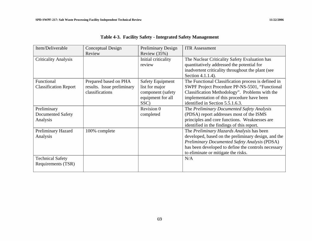
SPD-SWPF-217: Salt Waste Processing Facility Independent Technical Review 11/22/2006
69
Table 4-3. Facility Safety - Integrated Safety Management
Item/Deliverable Conceptual Design
Review Preliminary Design Review (35%)
ITR Assessment
Criticality Analysis
Initial criticality review
The Nuclear Criticality Safety Evaluation has quantitatively addressed the potential for inadvertent criticality throughout the plant (see Section 4.1.1.4).
Functional Classification Report
Prepared based on PHA results. Issue preliminary classifications
Safety Equipment list for major component (safety equipment for all SSC)
The Functional Classification process is defined in SWPF Project Procedure PP-NS-5501, “Functional Classification Methodology”. Problems with the implementation of this procedure have been identified in Section 5.5.1.6.3.
Preliminary Documented Safety Analysis
Revision 0 completed
The Preliminary Documented Safety Analysis (PDSA) report addresses most of the ISMS principles and core functions. Weaknesses are identified in the findings of this report.
Preliminary Hazard Analysis
100% complete The Preliminary Hazards Analysis has been developed, based on the preliminary design, and the Preliminary Documented Safety Analysis (PDSA) has been developed to define the controls necessary to eliminate or mitigate the risks.
Technical Safety Requirements (TSR)
N/A

SPD-SWPF-217: Salt Waste Processing Facility Independent Technical Review 11/22/2006
4.4 QUALITY ASSURANCE 4.4.1 ISO-9001 QA Assessments and Corrective Action Results 4.4.1.1 Summary of response to LOI II.d.1 “Were QA assessments of ISO-9001 implementation effective in identifying issues in preliminary design and have corrective actions been taken?” The EPC evaluates the effectiveness of implementation through audits and surveillances. Audits are performed as part of the corporate internal audit program and tend to be more programmatic in nature, i.e., focusing on project management, cost, personnel safety, etc. Under the ISO-9001 program, surveillances are the more effective method for identifying issues related to the process of creating the preliminary design. Additionally, surveillance reports indicate that corrective action was effectively identified and implemented. Suggested Improvement 4.4-17: As the NQA-1 program becomes fully implemented more NQA-1 compliant audits will need to be performed. 4.4.2 Impacts of NQA-1 Conversion after Preliminary Design 4.4.2.1 Summary of response to LOI II.d.2 “Have the impacts of conversion to NQA-1 after preliminary design been assessed adequately?” The assessment of the impacts of conversion is not adequate. The EPC conducted a gap analysis to determine what parts of their existing ISO-9001 program needed to be modified. The result of this gap analysis led to recommendations to change more than 30 procedures. This gap analysis does not include an analysis of the impact of the changes on design work that has been performed. The EPC is committed to acquiring a QA resource to lead an effort to evaluate the impact of changes on existing work. The QA resource is expected to begin by mid-November. This evaluation will involve examining the changes made to procedures and evaluating what impact there is on previous work. A specific area that should be examined is the quality program for design inputs, e.g., research reports, test results, analysis done by vendors or universities, etc. Some examples of design inputs where the quality program may need to be determined were noted in reference sections of Calculations No: C-CLC-J-00015 and M-CLC-J-0007. In some cases, the item may have been intended for informational purposes only, but this is not clear from a review of the package. Suggested Improvement 4.4-18: Continue planned effort using an outside QA resource to evaluate the impacts of conversion to NQA-1 on completed design work.
70

SPD-SWPF-217: Salt Waste Processing Facility Independent Technical Review 11/22/2006
4.4.3 NQA-1 Impacts on Completed Design 4.4.3.1 Summary of response to LOI II.d.3 “Do the impacts of NQA-1 challenge any of the completed design?” From a quality perspective the impacts of NQA-1 will probably not challenge the completed design. The impacts will likely be deficiencies in documentation and records. As the impact of changes on the existing design is evaluated by the EPC, the specific issues related to design inputs, software usage, and control of procured items will be revealed and require appropriate corrective action. In cases where QA programs were less than adequate or nonexistent, a dedication process or a qualification process will be needed. 4.4.3.2 Computer software QA concerns The EPC SWPF Project Procedure “Preparation of Calculations”, PP-EN-5004 Revision 3, Section 6.3.1[91] does not require that calculations identify what operating environment the computer program was run on and whether the computer program was run within the parameters of the approved verification and validation. The recent revision may cover the intent of the parameters of the approved verification and validation, but it is not clear if the requirement as stated is sufficiently explicit. An example of where operating environment and use within approved parameters was not documented was Calculation No. C-CLC-J-00015. Also, individuals doing calculations must clearly understand that they can only use the computer program for the application for which it is approved, and that understanding should be documented in the calculation. In addition to revising the procedure, the calculation form should be revised as the means of documenting the operating environment and use information. Finally, there is no requirement in PP-EN-5004 Revision 3 to describe whether software is classified as single-use software. Single use software is defined in two procedures PP-EN-5004 and PP-GN-1017[92]. It is not clear whether software such as Wall Calc R3-2003, which was used in Calculation No. A-CLC-J-00011, is a single-use software or not. PP-EN-5004 Revision 3, Section 6.5.2 indicates that any software that is under a Condition Report (error was identified) is not to be used. It is not clear from the procedure that a mechanism exists to prevent the use of the software while the Condition Report is being resolved. A positive mechanism, such as formal notification to users with an acknowledgement and/or computer program removal from the approved baseline, is needed to assure no design activities are performed using the computer program that is in question. Area of Concern 4.4-20: Procedure PP-EN-5004 Revision 3 does not identify all needed software quality assurance requirements.
71
SPD-SWPF-217: Salt Waste Processing Facility Independent Technical Review 11/22/2006
Recommendation AC 4.4-20: Revise software procedure PP-EN-5004 to: (1) require identification of the approved operating environment for software that has been verified and validated and that the software was used within the parameters that it has been verified and validated for, (2) indicate whether software is single use or not, and (3) establish a mechanism to assure no design activities are performed using a computer program that is in question. iGrafx® Professional and Process 2005 was used to perform at least two calculations (M-CLC-J-00085 and M-CLC-J-00061). iGrafx is a software application similar to Microsoft® ExcelTM. iGrafx as a software application is approved; however, the calculations created by this tool are not. iGrafx should be treated like other application software, and the output created by iGrafx should be verified and validated like Excel spreadsheets. There were two examples where the Software Quality Assurance Plan (SQAP) documentation did not match the verification and validation results or the user environment: (1) HydroCAD® Version 7.0[93]. The Software Installation and Checkout Form indicates the installation was done in Windows 2000TM. Some of the installations are Windows XPTM. The software was not evaluated for this environment. (2) The SQAP Mass Balance Model[94] indicates the application would be either run in Excel 2000 or 2003. Tests were only run in Excel 2000. This would make any use of the tool using Excel 2003 invalid. Area of Concern 4.4-21: The software management program is not fully understood and implemented. Recommendation AC 4.4-21: It is recommended that: (1) computer programs created using applications such as iGrafx be identified in the software registry and verified and validated (V&V) as appropriate, (2) confirm that verification and validation results and user environments are equivalent for all calculations, revise V&V results if necessary, and (3) consider conducting additional training for personnel who use software in calculations emphasizing the importance of using the software within the validated parameters and documenting that understanding. 4.5 REFERENCES (1) Q-PHQ-J-00001, Revision 0, Salt Waste Processing Facility Project Preliminary
Hazard Analysis. Parsons, Aiken, South Carolina. October 15, 2004. (2) V-PHR-J-00001, Revision B, Hazard and Operability Review (HAZOP). Parsons,
Aiken, South Carolina. March 7, 2005. (3) V-PHR-J-00002, Revision 0, Hazard and Operability 2 Review Summary Report.
Parsons, Aiken, South Carolina. August 24, 2006. (4) S-SAR-J-00001, Revision D, Preliminary Documented Safety Analysis. Parsons,
Aiken, South Carolina. July 17, 2006. (5) 10 CFR 851, Development and approval of the worker safety and health program.
February 9, 2006. (6) P-DRR-J-00002, Book 1: PDR Design Control Drawings, 5.0 Radiation Zone
Drawings, (A-AD-J-0007; A-AD-J-0008 Sheets 1&2; A-AD-J-0009)
72

SPD-SWPF-217: Salt Waste Processing Facility Independent Technical Review 11/22/2006
(7) S-CIP-J-00004, Revision 0, Radiation Protection Program for 10 CFR 835 (“RPP”). Parsons, Aiken, South Carolina. August 31, 2006
(8) S-EIP-J-00004, Revision 0, ALARA Design Review Report. Parsons, Aiken, South Carolina. September 13, 2006.
(9) PP-RP-4501, Revision 1, ALARA Review Procedure. Parsons, Aiken, South Carolina. April 25, 2006.
(10) V-PHR-J-00002, Revision 0, Hazard and Operability 2 Review Summary Report. Parsons, Aiken, South Carolina. August 24, 2006.
(11) P-ESR-J-00011, Revision 0, Operations Requirements Document. Parsons, Aiken, South Carolina. July 11, 2006.
(12) S-CIP-J-00003, Revision A2 (draft), 10 CFR 851 Worker Health and Safety Plan. Parsons, Aiken, South Carolina.
(13) Anderson, U. Material Handling presentation: 35% Design Status Review. Parsons, Aiken, South Carolina. September 19, 2006.
(14) S-NCS-J-00001, Revision 0, Nuclear Criticality Safety Evaluation: Salt Waste Processing Facility Operations. Parsons, Aiken, South Carolina. April 21, 2005.
(15) ANSI/ANS 8.1-1998, Nuclear Criticality Safety in Operations with Fissionable Material Outside Reactors. American National Standards Institute. 1998.
(16) P-CRT-J-0082, Revision A1, Revision Salt Waste Processing Facility Project (SWPF) Safety Analysis Mass Balance Run. Parsons, Aiken, South Carolina. August 24, 2004.
(17) P-ESR-J-00013, Revision 0, Analytical Laboratory Operations Plan. Parsons, Aiken, South Carolina. July 26, 2006.
(18) P-ESR-J-00001, Revision 1, Mass Balance Model Summary Description. Parsons, Aiken, South Carolina. September 29, 2005.
(19) 10 CFR 835, Energy: Chapter III: Department of Energy: Occupational Radiation Protection. 2003.
(20) PP-RP-4501, Revision 1, As Low As Reasonably Achievable (ALARA) Review. Parsons, Aiken, South Carolina. April 25, 2006.
(21) P-DB-J-00004, Revision B (Page 1 of 13); Balance of Plant Basis of Design. Parsons, Aiken, South Carolina. October 4, 2006.
(22) P-DRR-J-0002, Book 1: PDR Design Control Drawings, 8.0 Mechanical Flow Diagrams (P-PL-J-0011, Rev. E)
(23) P-DRR-J-0002, Book 1: PDR Design Control Drawings, 8.0 Mechanical Flow Diagrams (P-PL-J-0012, Rev. D)
(24) P-DRR-J-0002, Book 2: Discipline Drawings, 8.0 Material Handling (P-PL-J-0062, Rev. B)
(25) P-DRR-J-0002, Book 2: Discipline Drawings, 8.0 Material Handling (P-PL-J-0001, Rev. B)
(26) P-DRR-J-0002, Book 2: Discipline Drawings, 8.0 Material Handling (P-PL-J-0051, Rev. B)
(27) P-DRR-J-0002, Book 2: Discipline Drawings, 8.0 Material Handling (P-PL-J-0054, Rev. B)
(28) P-DRR-J-0002, Book 2: Discipline Drawings, 8.0 Material Handling (P-PL-J-0020, Rev. C)
73

SPD-SWPF-217: Salt Waste Processing Facility Independent Technical Review 11/22/2006
(29) P-DRR-J-0002, Book 1: PDR Design Control Drawings, 8.0 Mechanical Flow Diagrams (P-PL-J-0008, Rev. B); P-DRR-J-0002, Book 2: Discipline Drawings, 8.0 Material Handling (P-PL-J-0064, Rev. B)
(30) P-DRR-J-0002, Book 1: PDR Design Control Drawings, 8.0 Mechanical Flow Diagrams (P-PL-J-0008, Rev. B); P-DRR-J-0002, Book 2: Discipline Drawings, 8.0 Material Handling (P-PL-J-0063, Rev. B)
(31) P-DRR-J-0002, Book 1: PDR Design Control Drawings, 8.0 Mechanical Flow Diagrams (P-PL-J-0008, Rev. B); P-DRR-J-0002, Book 2: Discipline Drawings, 8.0 Material Handling (P-PL-J-0065, Rev. B)
(32) P-DRR-J-0002, Book 1: PDR Design Control Drawings, 8.0 Mechanical Flow Diagrams (P-PL-J-0009, Rev. E); P-DRR-J-0002, Book 2: Discipline Drawings, 8.0 Material Handling (P-PL-J-0059, Rev. B)
(33) P-DRR-J-0002, Book 1: PDR Design Control Drawings, 8.0 Mechanical Flow Diagrams (P-PL-J-0010, Rev. E)
(34) P-DRR-J-0002, Book 1: PDR Design Control Documents, 8.0 Mechanical Flow Diagrams (P-PL-J-0014, Rev. D); P-DRR-J-0002, Book 2: Discipline Drawings, 8.0 Material Handling (P- PL-J-0058, Rev. B)
(35) P-DRR-J-0002, Book 2: Discipline Drawings, 8.0 Material Handling (P-PL-J-0061, Rev. B)
(36) P-DRR-J-0002, Book 1: PDR Design Control Documents, 8.0 Mechanical Flow Diagrams (P-PL-J-0009, Rev. D); P-DRR-J-0002, Book 2: Discipline Drawings, 8.0 Material Handling (PL-J-0011, Rev. E)
(37) P-DRR-J-0002, Book 1: PDR Design Control, 8.0 Mechanical Flow Diagrams (P-PL-J-0013, Rev. D)
(38) P-DRR-J-0002, Book 1: PDR Design Control, 8.0 Mechanical Flow Diagrams (P-PL-J-0011, Rev. E)
(39) P-DRR-J-0002, Book 1: PDR Design Control, 8.0 Mechanical Flow Diagrams (P-PL-J-0009, Rev. E)
(40) P-DRR-J-0002, Book 1: PDR Design Control, 8.0 Mechanical Flow Diagrams (P-PL-J-0011, Rev. E); P-DRR-J-0002, Book 2: Discipline Drawings, 8.0 Material Handling (P-PB-J-0001, Rev. B)
(41) P-DRR-J-0002, Book 2: Discipline Drawings, 8.0 Material Handling (P-PB-J-0003, Rev. B)
(42) P-DRR-J-0002, Book 1: PDR Design Control, 8.0 Mechanical Flow Diagrams (P-PL-J-0012, Rev. D)
(43) P-DDR-J-002, Book 2: Discipline Drawings, 8.0 Material Handling (G-P1-J-00015, Rev. A2)
(44) P-DB-J-00004, Revision B (Page 13 of 13), Balance of Plant Basis of Design. Parsons, Aiken, South Carolina. October 4, 2006.
(45) DOE P 450.4, Safety Management System Policy, October 15, 1996. (46) ISMS DEAR Clause: 970.5223-1 Integration of environment, safety, & health into
work planning & execution. (47) S-PP-J-00001, Revision 0, SWPF Personnel Selection, Training and Qualification
Plan (and Appendices). Parsons, Aiken, South Carolina. July 13, 2006. (48) Q-EIP-J-00002, Revision A2, SWPF Project Impacts, Objectives, Targets, and
Environmental Management Plans. Parsons, Aiken, South Carolina. June 13, 2006.
74
SPD-SWPF-217: Salt Waste Processing Facility Independent Technical Review 11/22/2006
(49) V-RPT-J-0107, Revision 0, SWPF WBS Dictionary. Parsons, Aiken, South Carolina. June 30, 2006
(50) ISMS DEAR Clause: 970.5204-2 Laws, regulations, and DOE directives (51) DOE G 450.4-1B, Integrated Safety Management System Guide, March 1, 2001. (52) DOE HDBK-3027-99, Integrated Safety Management System (ISMS) Verification
Team Leader Handbook, June 1999. (53) DOE-SR Contract DE-AC09-02SR22210; Contract No. DE-AC09-02SR22210, Salt
Waste Processing Facility New DOE Directives (7/03/04 to 7/16/04) (54) SRM 300.1.1B, DOE-SR Functions, Responsibilities and Authorities Procedure (55) SRM 400.1.1B, SRS Safety Management System Description Manual (56) SPD-SWPF-001 Revision 1, Baseline Change Control Procedure for the Salt Waste
Processing Facility, U.S. Department of Energy-Savannah River Operations. July 16, 2004.
(57) SPD-SWPF-002 Revision 1, Design Documentation Administration for the Salt Waste Processing Facility. U.S. Department of Energy-Savannah River Operations. August 28, 2006.
(58) SPD-SWPF-003 Revision 0, Document Control. U.S. Department of Energy-Savannah River Operations. October 1, 2002.
(59) SPD-SWPF-P-0004 Revision 7, Desktop Instruction for Issuing Approved Deliverables. U.S. Department of Energy-Savannah River Operations. July 22, 2005.
(60) SPD-SWPF-P-0005 Revision 0, Review & Approval of Engineering, Procurement & Construction Contractor S/RID for Salt Waste Processing Facility. U.S. Department of Energy-Savannah River Operations. July 22, 2005.
(61) SPD-SWPF-P-0006 Revision 0, Directives Compliance Procedure for the Salt Waste Processing Facility. U.S. Department of Energy-Savannah River Operations. April 12, 2006.
(62) SPD-SWPF-P-0007 Revision 0, Entering SPD Assessments into the Site Issues Management and Technical Assessment System. U.S. Department of Energy-Savannah River Operations. May 1, 2006.
(63). SPD-SWPF-0014, Revision 2, Salt Waste Processing Facility Integrated Project Team Charter. U.S. Department of Energy-Savannah River Operations. May 24, 2006
(64) V-CRT-J-0002, Revision 1, Salt Waste Processing Facility Project Preliminary Project Execution Plan. Parsons, Aiken, South Carolina. November 14, 2003.
(65) V-ESR-J-00022, Revision 1, Salt Waste Processing Facility Project Document Control Interface Control Document (ICD-22). Parsons, Aiken, South Carolina. March 31, 2006.
(66) V-ESR-J-00025, Revision 0, Salt Waste Processing Facility Project Interface Management Plan. Parsons, Aiken, South Carolina. June 25, 2004.
(67) F-FHA-J-00001, Revision C, SWPF Fire Hazard Analysis. Parsons, Aiken, South Carolina. April 15, 2005.
(68) P-CDM-J-00001, Revision 0, SWPF Configuration Management Plan. Parsons, Aiken, South Carolina. January 12, 2006.
(69) P-CRT-J-0045, Revision 1, SWPF Operations Requirements Document. Parsons, Aiken, South Carolina. September 15, 2003.
75
SPD-SWPF-217: Salt Waste Processing Facility Independent Technical Review 11/22/2006
(70) P-CRT-J-0087, SWPF Project Integrated Safety Management System Policy. Parsons, Aiken, South Carolina. December 6, 2005.
(71) P-DB-J-00004, Revision A2, SWPF Balance of Plant Basis of Design. Parsons, Aiken, South Carolina. June 21, 2006.
(72) P-DB-J-00002, Revision C, SWPF Design Criteria Database (Attachments). Parsons, Aiken, South Carolina. June 14, 2006.
(73) P-DB-J-00003, Revision B, SWPF Process Basis of Design. Parsons, Aiken, South Carolina. March 15, 2006.
(74) P-ESR-J-00004, Revision A2, SWPF Commissioning Strategy. Parsons, Aiken, South Carolina. February 7, 2005.
(75) P-SD-J-00001, Revision A2, SWPF Performance Assurance System Description. Parsons, Aiken, South Carolina. August 15, 2006.
(76) P-SPC-J-00001, Revision B3, SWPF Feed Strategy and Product and Secondary Waste Specification. Parsons, Aiken, South Carolina. November 10, 2004.
(77) P-SPC-J-00002, Revision C2, SWPF Functional Specification. Parsons, Aiken, South Carolina. September 6, 2005.
(78) P-TPL-J-00001, Revision D, SWPF Construction, Procurement and Acceptance Testing Plan. Parsons, Aiken, South Carolina. June 27, 2006.
(79) Q-PLN-J-0099, Revision A2, SWPF Project Pollution Prevention Plan. Parsons, Aiken, South Carolina. May 4, 2006.
(80) Q-PLN-J-0100, Revision A2, SWPF Environmental Management Systems Program Description. Parsons, Aiken, South Carolina. April 19, 2006.
(81) S-CIP-J-00005, Revision A2, SWPF Construction Health and Safety Plan for CD-3. Parsons, Aiken, South Carolina. July 28, 2006.
(82) S-EIP-J-00001, Revision 0, SWPF Environmental Plan. Parsons, Aiken, South Carolina. January 11, 2005.
(83) S-EIP-J-00003, Revision A2, SWPF Industrial Chemical Safety Design Review. Parsons, Aiken, South Carolina. August 22, 2006.
(84) S-EIP-J-00004, Revision A2, SWPF Preliminary ALARA Report. Parsons, Aiken, South Carolina. August 24, 2006.
(85) S-RCP-J-00001, Revision 1, SWPF Standards Requirements Identification Document (and Appendix A). Parsons, Aiken, South Carolina. October 26, 2006.
(86) V-ESR-J-00012, Revision 1, SWPF Emergency Response Interface Control Document (ICD-12). Parsons, Aiken, South Carolina. November 16, 2005.
(87) V-ESR-J-00017, Revision 1, SWPF Fire Protection Water System Interface Control Document (ICD-17). Parsons, Aiken, South Carolina. March 16, 2006.
(88) V-ESR-J-00018, Revision 1, SWPF Work Controls Interface Control Document (ICD-18). Parsons, Aiken, South Carolina. July 21, 2006.
(89) V-IM-J-00001, Revision 0A2, SWPF Project Organization, Roles and Responsibilities Manual. Parsons, Aiken, South Carolina. April 15, 2006.
(90) V-QP-J-00001, Revision 0, SWPF Quality Assurance Plan. Parsons, Aiken, South Carolina. July 27, 2006
(91) PP-EN-5004, Revision 3, Preparation of Calculations. Parsons, Aiken, South Carolina. September 13, 2006.
(92) PP-GN-1017, Revision 1, Computer Software Management. Parsons, Aiken, South Carolina. August 25, 2006.
76

SPD-SWPF-217: Salt Waste Processing Facility Independent Technical Review 11/22/2006
(93) HydroCAD Version 7.0, 05-B-HYDROCAD_7.0, October 4, 2005. (94) SQAP Mass Balance Model, Version 0B. Parsons, Aiken, South Carolina.
77

SPD-SWPF-217: Salt Waste Processing Facility Independent Technical Review 11/22/2006
5.0 ENGINEERING 5.1 PROCESS DESIGN A summary of findings related to process design deliverables is included in Table 5-1. 5.1.1 Maturity of Process Design This evaluation began with a review of the criteria which the design was to implement. The implementing documents were then reviewed to determine the thoroughness of the design and the technical implementation of the criteria. The ITR also evaluated the test programs plans and results for CSSX and MST/Filtrations for any shortcomings which need to be resolved which may affect the maturity of the design. Deficiencies identified by the ITR were discussed with the EPC Process Engineering Group and actions to address them are being planned or considered by the EPC. The design review is covered in Section 5.1.1.1 through 5.1.1.3 and the process and test plan reviews are covered in Sections 5.1.1.4 through 5.1.1.16. 5.1.1.1 Summary of response to LOI III.a.1 “Does the maturity of the process design support 35% completion status, as defined in Salt Processing Division procedure SPD-SWPF-002?” The assessment specifically determined the maturity of the process design supports 35% completion status. However, there are deficiencies that need to be resolved before much further process design is completed. These deficiencies are identified in the sections which follow. Based on discussions with the EPC Process Group, the EPC is aware of these deficiencies and working to resolve them. A number of observations were discussed with the EPC and actions to address them have been initiated. The following sections include general discussion of each of the major process steps, and comments based on general process experience, a discussion related to future test plans. 5.1.1.2 Review of the applicable process design criteria The following specific documents were identified to contain the process design criteria:
(1) Standard/Requirements Identification Document (S-RCP-J-00001, Revision 1, June 26, 2006)[1]
(2) Feed Strategy and Product and Secondary Waste Specification (P-SPC-J-00001, Revision 0, December 22, 20040[2]
(3) Functional Specification (P-SPC-J-00002, Revision 0, January 11, 2005)[3] (4) Process Basis of Design (P-DB-J-00003, Revision 0, June 1, 2006)[4] (5) Operations Requirements Document (P-ESR-J-00011, Revision 0, July 11,
2006)[5]
78
SPD-SWPF-217: Salt Waste Processing Facility Independent Technical Review 11/22/2006
(6) Salt Waste Processing Facility Project Design Criteria Database (P-DB-J-0002, Revision D, September 12, 2006)[6]
(7) Design Documentation Administration for the Salt Waste Processing Facility (SPD-SWPF-002, Revision 1, August 2006)[7]
The criteria documents[1-7] are very consistent and agree with the major deliverables such as the PFD. This is a requirement for determining that the CD-2 design is complete and that the project should go forward. Review of the requirement documents[1-7] indicated there is the need to close several open items. Examples of this include the following:
• Function Specification, pages 5 and 6, which state “as the design matures”. The design should have matured by this point, considering the length of time since the documents were released. As a minimum, there should be some documentation that indicates that design is mature.
• Similarly, Functional Specification, page 4, states an “initial set of environmental
requirements” for the Facility have been identified. Again, the documents or a document, should confirm that the environmental requirements have been completed or identify specifics which are not complete.
• Functional Specification, (page 5) Section 3.2, states new testing has been completed,
but it is not clear that the new results have been incorporated into the design. Suggested Improvement 5.1-19: These documents[1-7] also contain “assumptions” which will need to be closed and assurances should be established that these assumptions are valid or will not affect the preliminary design significantly. The EPC should prepare a document which lists the updated status of these assumptions in the documents or revise the documents with statements which are more up-to-date. Suggested Improvement 5.1-20: For personnel not familiar with the project scope it would be beneficial to identify the scope on the PFD (page 3 of the functional specification) which appears in several documents. This could be similar format [dotted lines] as utilized in Figure 1-1 of this document to distinguish the scope between Alpha Strike, Cesium Removal, and Alpha Finishing. 5.1.1.2.1 Standard/Requirements Identification Document The Standard/Requirements Identification Document (S/RID), S-RCP-J-00001[1] has been recently issued and is considered by DOE to include applicable Federal, State, and local laws and regulations. The document was issued after resolution and incorporation of DOE comments. The ITR review of other requirements documents (References 1-7) considered the S/RID as the upper tier level of requirements which the other documents need to follow.
79
SPD-SWPF-217: Salt Waste Processing Facility Independent Technical Review 11/22/2006
5.1.1.2.2 Feed Strategy and Product and Secondary Waste Specification The Executive Summary of the Feed Strategy and Product and Secondary Waste Specification[2] states that two of the tanks exceed the specific activity limits established for the SWPF Safety Basis. The document also identifies open issues with the feed and with the current WAC for both DWPF and the Saltstone production facility. There are differences between the contract and newer WAC specifications, which are apparently developed or being developed. Since the document is relatively old (December 2004) these issues may well be in active resolution. However, if they are not, they need to be resolved soon in order for the design to proceed. Technical Issue 5.1-4: It appears that the SWPF feed, product, and secondary waste streams requirements need to be updated or re-established. Recommendation TI 5.1-4: Set a high priority on negotiating new WACs for both Saltstone and DWPF, get these WACs approved by the interface parties, and replace those currently in the contract documents. Also, establish the specifics of acceptance of waste feed from the tank farm. After agreements are reached, provide the quantitative design information in the Interface Control Documents. 5.1.1.2.3 Functional Specification The Functional Specification[3] establishes the amount of dilution water which will be needed to dilute the salt cake from 37 million gallons to 84.7 million gallons. Since this is a critical design number, it is assumed the project has established a firm basis for this number, to assure process design rate is adequately sized. The amount of dilution water was apparently determined during early stages of mission verification. The mission verification process established and confirmed the procurement of a 3.0 Mgal/yr-capacity plant (based on feed at 6.44 molar of sodium. The estimates of effluents, emissions, and solid waste are couched in terms “as-the-design-matures”. Environmental and permit requirements could be significant cause for re-design if the mature design does not maintain the emission estimates in the preliminary design and the CD-2 design report. Section 4.1 of the Functional Specification discusses the recycle which is built into the design but it is not clear that the overall process rate rigorously determines the process capability to process in the given time frame. All indications are that the design accounts for this. This could be stated in the Process Description to avoid potential misunderstandings. 5.1.1.2.4 SWPF Process Basis of Design The SWPF Process Basis of Design[4] document does not provide clear definitions of “design capacity” and “peak throughput”. These definitions can frequently cause misunderstandings and hence, mistakes regarding actual tank volume. From the detailed calculations, it is clear the volumes are used consistently in determining tank sizes. This document and other
80
SPD-SWPF-217: Salt Waste Processing Facility Independent Technical Review 11/22/2006
requirements documents present consistent equipment lists. Assuming the equipment list provides actual useable volumes of tanks, there is conservatism in the tanks being provided. Although the heel volume is not identified in the Process Basis of design, calculations show the heel volume has been adequately considered. For completeness the heel volume could be presented in Section 3.1.2.1, page 4 where freeboard is discussed. The document should also specifically define ‘design capacity’ and ‘peak throughput’. Table 3-2 does not provide sampling times while Table 3-4 does. This seems to indicate that Table 3-2 underestimates the complete cycle time. Are they significant and should they be added? The document has several ‘assumed’ or ‘target values’ and assurance is needed that they are correct. Process water, flush water, and deionized water have specific areas utilized. Since process water contains dissolved chemicals, it is not clear that the use of Process Water in certain areas will not affect the chemistry, the volumes to be processed, and the amount of waste produced. Suggested Improvement 5.1-21: The discussion in Section 3.4 of the Process Basis of Design (regarding the Cold Chemicals Area) should identify all safety concerns. Since the facility and process use acid and caustic, the danger of mixing acid and caustic needs to be identified. The SWPF Process Basis of Design should also quantify the “shielding requirements”. 5.1.1.2.5 Operations Requirements Document The Operations Requirements Document[5] states that the document provides the basis that will be used by the EPC to integrate operability, maintenance, and testability requirements into the SPF design. The Operations Requirements Document also provides the framework for development of P-ESR-J-0004 (SWPF Commissioning Strategy[8]). This document has been reviewed to determine that requirements were consistent with similar requirements documents and to develop an understanding of the requirements for the design of the facilities and systems. The review determined the operations requirements were complementary and consistent with the other documents. Specific evaluations that address commissioning are provided in Section 5.7.1.2. P-ESR-J-00011 was also reviewed to determine the adequacy for Operations and Maintenance for the CD-2 stage of design. The Operations and Requirements Document and the Commissioning Strategy were reviewed for adequacy at the CD-2 state of design. Operations is commended for recognizing the need to verify the Preliminary Documented Safety Analysis. The other testing objectives are also well founded. The overview provided in Section 4 lays out a well conceived listing and sequence of activities from construction testing through operations. Specific positive points are the plans to develop a Design Requirements Matrix to link acceptance criteria to the design basis and
81
SPD-SWPF-217: Salt Waste Processing Facility Independent Technical Review 11/22/2006
to identify the test which accomplish the assurance of meeting the design requirements. The sequence identifies and indicates that plans will be in place on a defined schedule. The document recognizes the value of a readiness self-assessment before the start of cold commissioning. Hot tie-ins are not planned until the completion of cold commissioning. The plans to use low radioactivity before high radioactivity are appropriate. Sections 6 and 10 through 13 provide specific facility layout requirements which are thorough, complete, and well thought-out. However, the use of the term “recommended” makes it unclear what are the true “requirements”. Although most of these recommendations are included in the Design Criteria Database, there seem to be some significant omissions. The provisions required in the design for Reliability, Availability, Maintainability, and Inspectability are both thorough and appropriate. Positive Finding 5.1-6: Including Operation and Maintenance early in the design phase is excellent and recognition of the need to operate within the Documented Safety Analysis provides assurance of completeness of the preliminary design for CD-2. These items are examples of the good operation and maintenance philosophy developed for the project and provides assurance of the completion of Preliminary Design. Sections 6 and 7 provide excellent and detailed plans for Operation, Maintenance and Staffing Plans. It is suggested that the EPC maintain active involvement of Operations/Commissioning staff throughout the remainder of design. 5.1.1.2.6 Facility Project Design Criteria Database The Design Criteria Database (DCD)[6] consists of listings in Attachments A and B. The purpose of the document is not clear since it is being developed after the preliminary design has been completed. Attachment A contains many codes, standards, and DOE regulations. The specific criteria in Attachment B utilize only a very few of these. In addition, the criteria in the DCD do not include all of the apparent criteria in the design requirements documents identified in Section 5.1.1.2 (References 1 through 5). It is not clear whether “design objectives” are criteria or not since some are listed in the DCD and others are not. The fact that the Design Criteria Database is still in “draft” form raises a question as to how the design proceeded without a signed out Design Criteria Database. Attachment A [Design Criteria Database Code of Record] does not include the items listed in the SWPF Standards/Requirements Identification Document; this seems to be a major discrepancy. The SWPF Operations Requirements Document, Section 2.4, states that these requirements are captured in the SWPF Process Basis of Design and the SWPF Balance of Plant Basis of Design. The Design Criteria Database would capture the requirements from all of these documents. It appears to capture some of the requirements in the Operations Requirements Document, but none of the SWPF Process Basis of Design or the SWPF Balance of Plant Basis of Design.
82
SPD-SWPF-217: Salt Waste Processing Facility Independent Technical Review 11/22/2006
Suggested Improvement 5.1-22: The Design Criteria Database is not thorough and does not describe its purpose and its utilization. It is not consistent with the S/RID document. There do not appear to be any specific radiation shielding and ALARA requirements as identified in Section 4.1.1.7.1. The Design Criteria Database document does list 10 CFR 835 (but only high level requirements) and does not address Project Procedure PP-RP-4501, As Low As Reasonably Achievable (ALARA) Review, Revision 1, April 25, 2006. The EPC is encouraged to include a discussion in the document regarding the purpose of the document and how it is to be utilized by project staff. The discussion should also define how the attachments were prepared and how some specific criteria were included and other excluded. The document should be upgraded for consistency with the SWPF S/RID. 5.1.1.3 Evaluation of the implementing documents Specific Implementing Documents which were reviewed include:
(1) Process Flow Diagrams [As listed in (CD-2) Critical Decision – 2 Package (OUO), Attachment A – 35% Design Package, Book 1: PDR Design Control Drawings, 1.0 Process Flow Diagrams][9]
(2) Piping and Instrumentation Diagrams [As listed in Livelink (CD-2) Critical Decision – 2 Package (OUO), Attachment A – 35% Design Package, Book 1: PDR Design Control Drawings, 2.0 Piping and Instrumentation Diagrams][10]
(3) Operations Assessment and Tank Utilization Models (P-ESR-J-00003, Revision 0, January 19, 2006)[11]
(4) Design Process Description (P-PCD-J-00001, Revision 0, July 8, 2005)[12] (5) Nuclear Criticality Safety Evaluation: Salt Waste Processing Facility Operations
(S-NCS-J-00001, Revision 9, April 21, 2005)[13] (6) Recommended SWPF Waste Compliance Plan for Transfers to the Defense
Waste Processing Facility and the Saltstone Production Facility (X-WCP-J-00001, Revision 0, August 24, 2006)[14]
(7) Commissioning Strategy [P-ESR-J-00004, Revision 1 September 13, 2006)[8] These documents were reviewed and evaluated for consistency and incorporation of the criteria established by the documents listed in Section 5.1.1.2. 5.1.1.3.1 Process Flow Diagrams and Piping and Instrumentation Diagrams The Process Flow Diagrams (PFDs) and Piping and Instrumentation Diagrams (P&IDs) were found to be complete for the 35% design review. The ITR Team emphasizes the importance of minimizing and controlling changes to these documents. There can be no guarantee that future changes will not be required, but cost impacts can be significant if changes include instrumentation, piping, and even wall penetrations. The PFDs[9] are in excellent agreement with the Basis of Design documents and the Process Description. The drawings that were reviewed have several items circled. It is expected the documents will have the circles removed and will be officially signed for their use in the CD-2 package. The requirements documents are well laid out so that they can be compared to the PFDs.
83
SPD-SWPF-217: Salt Waste Processing Facility Independent Technical Review 11/22/2006
Section 3.4 (the Cold Chemicals Area in the Process Basis of Design) should identify all safety concerns. Since the facility and process use acid and caustic, the PFDs and applicable P&IDs[10] should identify the danger of mixing acid and caustic. These same safety concerns need to be specifically addressed on the PFDs and lower tier implementing documents. Although the PFDs do not have the sampling locations identified, the P&IDs have included the sampling points. This is an acceptable approach to identifying sampling requirements. Area of Concern 5.1-22: During the review of the PFDs/P&IDs the design only provided for vacuum protection with a relief valve on the common header. Although redundant relief valves are provided, this is considered insufficient protection for the number of vessels and tanks in the dark cell. The piping design required a special layout for maintenance of the relief valves which adds cost. Lessons learned from tanks and vessels failure when subject to vacuum (when pumping out of the tanks) demonstrated that additional protection is needed. Recommendation AC 5.1-22: Design the vessels/tanks for full vacuum. The additional cost will eliminate a large economic risk. 5.1.1.3.2 General Arrangements The General Arrangement drawings[11] issued with the CD-2 package include the SWPF Process Building. They show all necessary elevations and most of the major equipment. In addition, they show offices, laboratories, etc. Recent changes in the P&IDs will result in some additions, deletions, and changes to these drawings. General Arrangements for other smaller buildings were not provided with the CD-2 package, (at least not in Attachment 1B, Section 4). However, these are much smaller, less complex buildings and the general arrangement drawings are essentially complete and are judged to meet the CD-2 requirement. The General Arrangements were reviewed to evaluate overall status and selective specifics for radiation protection, operations requirements, and safety related potential issues. The general arrangements were found to incorporate the specific criteria evaluated. They provide a logical layout for the overall plant design and equipment arrangements. Positive Finding 5.1-7: The General Arrangement drawings show a very detailed plant layout, and the selected specific designs that the ITR reviewed, were found to have incorporated applicable design criteria.
84

SPD-SWPF-217: Salt Waste Processing Facility Independent Technical Review 11/22/2006
5.1.1.3.3 Operations Assessment and Tank Utilization Models The Operations Assessment and Tank Utilization Models document[12] was reviewed. Models were used in sizing of the tanks. The document compares early design tank sizes with the needed volumes through the Tank Utilization model. The current tank volumes at the time of the model runs did not exceed the volumes needed as determined from Tank Utilization model runs. Tank volumes have been increased over time to satisfy the design input information obtained from the model runs. Some of the assumptions in the Operations Assessment model such as services availability interfaces with the DWPF and Saltstone, and crane utilization should be updated during detailed design, as planned. The model should include the probability of the need to re-sample. The document does not mention V&V of the models. Suggested Improvement 5.1-23: It is suggested that the EPC provide updated model runs (as planned) using more recent design data. One source of design data to be incorporated is the centrifugal contactors failure data discussed in Section 5.1.1.13. When doing the additional model runs, the EPC should consider adding interface availabilities and the need for re-sampling, if samples are rejected or mis-analyzed. 5.1.1.3.4 Design Process Description The purpose of the Design Process Description document[13] is to describe the EPC design approach and methods to be used in the development of the SWPF design. The document provides a good summary history of the development of the process design from justification of the mission need through functional requirements and alternative analysis. This analysis provided a firm foundation for the process design and architecture selection. The document provides the roadmap to assure the plant has a firm safety basis through hazards analysis and the development of a Preliminary Documented Safety Analysis (PDSA). The PDSA determined the safety requirements early in the design and provided the ability to include the safety requirements. This complies with DOE O413.3 which emphasized including safety elements early in project designs. Suggested Improvement 5.1-24: The Design Process Description provides a good roadmap for establishing a firm foundation for design and the implementation of the design. It is suggested that the EPC utilize the document to create a “checklist” for making sure the plans described in the document are implemented. 5.1.1.3.5 Nuclear Criticality Safety Evaluation: Salt Waste Processing Facility The Nuclear Criticality Safety Evaluation: Salt Waste Processing Facility document[14] was reviewed and found consistent with the preliminary design. It provides a good explanation of the evaluation to assure that criticality is not credible. Conservative assumptions were made to provide assurance criticality would not be credible. In Section 5.3, the tank volume used in the calculation is 23,200 gallons while Section 5.1.1 states 35,000 gallons would be a
85
SPD-SWPF-217: Salt Waste Processing Facility Independent Technical Review 11/22/2006
conservative assumption. Since tank volumes are now more than 37,000 gallons, this should be updated for the most conservative potential case. 5.1.1.3.6 Recommended SWPF Waste Compliance Plan For Transfers to the Defense
Waste Processing Facility and the Saltstone Production Facility The purpose of the Waste Compliance Plan[15] is to plan for the transfer of waste to the DWPF and the Saltstone Production Facility. However, design input information and calculations show that the WAC limits are not met for all planned tank farms wastes expected to be transferred. The planning here requires a joint effort that relies on the waste input from the tank farm to SWPF. The design documents indicate that the WAC limits will be renegotiated. These negotiations should be in progress now. Some of the limits in the WAC which will be exceeded have no current treatment capability in the SWPF. This document has the same basic finding and recommendation which was stated in Section 5.1.1.2.2 as Technical Issue 5.1-4 and Recommendation TI 5.1-4. After the input feeds to SWPF and the waste transfers have been negotiated, the agreed upon transfers should be provided in the Interface Control Documents. 5.1.1.4 Particulate solids as a source of problems In a classic article, Merrow (see References 16-20) discussed how the presence of solids in the processing industry is the chief cause of operational problems. The Independent Process Analysis Corporation founded by Merrow studied of a number of process plants and attributed many process failures to improperly considering the presence of solids in the design. This has been the general experience in DuPont and other companies. Therefore, much attention has been paid in this ITR review as to how the design accounts for the presence of particulate solids. In general, while they have not been totally neglected, more needs to be done. Fortunately, at the 35% design level, most of these process corrections can be incorporated with minimum effort and cost impact to the SWPF project. 5.1.1.5 Input solid properties The solids in this SWPF process come from two sources: one is the undissolved solids brought over from the waste tanks, and the other is the added chemical, monosodium titanate (MST). The first must be defined by the operators of the plant (e.g., Design Requirement X-WCP-J-00001). It is understood that this will be an estimate based on only a few samples. It will be confirmed during actual operation before a batch transfer. This document emphasizes the chemical and overall solids (dissolved and undissolved combined) but neglects the particulate solids phase for which much subsequent equipment must be designed. Such data is available (e.g., in WSRC-RP-2003-0021[21]). From such data, an estimate of the chemical composition, solid density, particle size and distribution and concentration of the particulate phase can be made. The particle size should emphasize the maximum particle size to be expected. MST is an article of commerce so its particle size, particle size distribution and solid density are known. But approximately half the sludge to
86

SPD-SWPF-217: Salt Waste Processing Facility Independent Technical Review 11/22/2006
be handled will be waste from the SRS tank farms. From this data a “box” or “envelop” of physical particulate and solution properties can be made for use in mixer and flow design. This is the design envelop for the equipment and should be agreed to with SRS. In addition, once this envelop is defined the effects of material outside of this can be determined. Because the material is outside of the input box, special care needs to be taken. An example would be a slug of sludge. Because it is outside of the “box,” more washes and adjustment in filtration parameters may be required. If inadvertent transfers are made which are significantly out of specification there should be a transfer line back to the tank farm. Technical Issue 5.1-5: There is no clear definition of the properties of the undissolved solids coming in with the waste. Recommendation TI 5.1-5: Obtain characterization from SRS of the undissolved solids properties coming in with the waste. Use this information to determine an input property box or envelop. Develop actions to be taken with in equipment limitations to handle material outside the box. Provide the information in an Interface Control Document and assure both the tank farms and SWPF will accept the basis for transferring the waste to SWPF. 5.1.1.6 Slurry handling Industrial experience, particularly in the minerals industry, shows that there is a minimum velocity below which solids sit on the bottom of the pipe and are not transported (except perhaps as a sliding bed). Operating below this velocity often leads to plugging or unstable operation. For good operability, pipelines typically run at a velocity above this minimum transport velocity. In fact, it is common to run at a velocity at which the solids are picked up from a stopped flow and transported. A great deal of research has been completed to understand and to derive theory based, experimentally-verified empirical correlations. There are a number of books on slurry transport (the most recent by Shook and Gillis of Saskatchewan Research Council being one of the most practical). The current EPC methods for sizing lines and pumps (e.g., calculations M-CLC-J-00062) neglect the presence of solids. The methods should be supplemented by a calculation of minimum transport velocity for the particulates. If this is less than desired, then the calculation or design must be adjusted. A rough estimate is that this will probably not be necessary but the calculation involving solids transport must be done for completeness. EPC has already begun such calculations. Area of Concern 5.1-23: The methods for sizing lines and pumps are for clear fluids only. Recommendation AC 5.1-23: All lines should be checked to see that minimum transport velocity is exceeded for waste sludge and MST based on their particle sizes and density.
87

SPD-SWPF-217: Salt Waste Processing Facility Independent Technical Review 11/22/2006
5.1.1.7 Flushing A key strategy to avoid plugging in this facility is frequent flushing of solids containing lines. Engineering calculation M-CLC-J-00077 defines a flushing strategy with a specified flushing velocity of 4 ft/sec independent of pipe size. As discussed above, the transport velocity in general depends on the line size. The pump calculations give operating velocities of 4 to 8 ft/sec. To flush lines with velocities lower than transport velocities is illogical. Industrial practice is to use a velocity significantly higher than the transport velocities, but below any velocity that might cause erosion. For example, a flush velocity of 10 ft/sec. is common. Area of Concern 5.1-24: The flushing velocity is too low and is often less than the transport velocity. The flush velocity serves two purposes; to wash and dissolve any residual and to remove any particulates left behind. A minimum requirement is turbulent flow, but that it will occur at low velocities with such low viscosity fluids is uncertain. To remove any insoluble solids left behind, it is necessary to run at a higher velocity than the velocity which left the particles behind. To minimize the wash volume, high velocities are required. Experience with cleaning piping systems with automotive finishes and pigment slurries such as titanium dioxide have shown that high velocities can significantly reduce the flush volume. The limit on velocity is erosion which in common practice occurs at a velocity greater than 10 ft/sec. Recommendation AC 5.1-24: The flush velocity should be greater than 4 ft/sec and greater than the minimum transport velocity. A practical number is 10 ft/sec. 5.1.1.8 Pumps The Balance of Design document states that low shear pumps should be used. These are devices that will minimize attrition of particles which would adversely affect filter flux. This is a common phenomenon in the process industries. Extensive work at DuPont has shown that to avoid loss of filtration rate, the system needs to be “de-energized.” Attrition has been found to depend mainly on the power delivered to the system and the time this power is applied. In the SWPF process, power comes from the mixers, and the pumps. The pump power is due to system losses. The DuPont testing shows that because of long residence times, mixer attrition can be quite high and that again, because of high exposure time, recycle loops with back pressure valves also have high attrition. In general, the differences between pumps is small compared to the large changes seen by reducing recycle and only running mixers periodically, e.g., running mixers 15 minutes every hour, reduces energy input by 75%. In addition, the higher the concentration, the more the attrition which is caused by particle-particle collisions. Area of Concern 5.1-25: The only specification of a low shear system is for pumps. Recommendation AC 5.1-25: To minimize attrition damage to the particles that could impact filtration rate, the entire system must be evaluated based on power input and time to develop equipment and strategies to minimize loss of filtration rate.
88
SPD-SWPF-217: Salt Waste Processing Facility Independent Technical Review 11/22/2006
5.1.1.9 Air Pulse Agitator Test Plan The original test plan[22] suffered from lack of input from staff familiar with process mixing technology. None of the several good books in the field are referenced nor are any of the frequent survey articles in popular engineering journals. Knowledgeable staff from Savannah River National Laboratory and the EPC do not seem to have been consulted. This resulted in some false starts and some confused concepts. The initial tests were thus only an additional demonstration of a concept that had been demonstrated by others. The tests did give some useful information on the relations between air flow and pressure and resulting liquid flow and configurations.[23] Since a similar configuration to that used by AEA Technology was used, the design developed is probably close to optimum in geometry and flow. The absolute value of air and liquid flow is probably not correct as it is based on a simulant. Mixing for settling solids can encompass several different process results. One is off bottom suspension, where no solids remain on the bottom for more than a few seconds. If the settled bed is non-Newtonian and thick, then the initial goal of the mixing is to dilute and re-disperse this bed. This is the chief goal of the submersible jet pumps in the tank. Once dispersed, the solids must be kept off the bottom. Many solids lay on the bottom as discrete particles and this dispersing step does not exist. A different process result is the distribution of the solids vertically to some degree of uniformity. The mixing condition and relations for off bottom and distributed are different in terms of optimum geometry and physical property effects. Many processes involving mass transfer between solids and the surrounding liquid only require off bottom suspension. The liquid is sufficiently blended that vertical uniform solids distribution is not required. If samples are to be taken, vertically uniformity may be required. Area of Concern 5.1-26: The definition of mixing equipment for solids suspension is typically based on physical properties such as solids and liquid density, particle size and distribution, concentration and liquid viscosity. In the test results, hardly any of these properties are given (though in most cases they are known). Success was based on the ability to handle simulants. Little or no justification is given for the use of these simulants. Kaolin clay slurries are typically used as a rheological simulant not as a settling particle simulant. Kaolin clay might be justified in the testing of a long settled bed, but in that case, the yield strength would also be useful for comparison to data taken at Hanford and at SRS. Future testing of the Air Pluse Agitator (APA) units are to be combined with testing of the filtration units. In addition, better erosion data is needed and it is recommended stress data should be obtained. The studies of the failure of a unit at Sellafield THORP Plant and the extensive work being done at Hanford needs to be evaluated for the design of these units. The EPC Mechanical Design Group needs to be involved in this testing. See additional discussion concerning test program in Section 5.1.3.2.
89
SPD-SWPF-217: Salt Waste Processing Facility Independent Technical Review 11/22/2006
Recommendation AC 5.1-26: Expert input for future tests on process mixing is needed and should include: more physical properties need to be recorded during these tests, simulants similar in physical properties to those expected need to be used, and the liquid blend time should be measured. 5.1.1.10 APA Mixer Sizing Program The purpose of this work[24, 25] was apparently to relate air and liquid flow properties. It is not strictly a Mixer Sizing problem. The analysis is 57 pages. Some tacit and peculiar assumptions are made. A program for the mixing process results such as off bottom suspension and distribution is required. AEA Technology which makes similar units has no published correlations. There is some discussion of solids suspension with steady down pointed jets in the book “Handbook of Industrial Mixing” (Wiley 2001), however, a different dimensionless analysis will be required. An example is the use of the product of area and volume. The groups obtained bear little relation to the familiar Reynolds, Froude, and Fourier numbers and geometric ratios and have a lot of 1/5 powers. The literature on blending of large tanks mixed by steady jet mixers shows that geometry and geometric ratios are as important as turnover time. A test plan for APA design development is being developed. Area of Concern 5.1-27: The geometry chosen was similar to AEA Technology design. Testing allowed some optimization which leads to better design. The range of parameters tested was only acceptable for a demonstration and first cut design. Using this data for scale up is acceptable and was done with conservatism. Recommendation AC 5.1-27: Future testing must use a more realistic simulant than kaolin clay. Liquid phase blend time needs to be measured, and zone of influence needs to be determined. A model based on physical and fluid dynamic properties needs to be developed. A technical exchange with the WTP team at Bechtel and Battelle would be useful as they also are developing a test plan to determine similar information. 5.1.1.11 Centrifugal Contactors These devices have a long history in the nuclear industry. These devices perform three functions: pumping the two phase through them to the next stage; dispersions of the organics into the aqueous and centrifugal separation of the phases. They have been subjected to extensive testing on real and simulant waste.[26, 27, 28] The chemistry is well established. The plant design must produce an equivalent fluid dynamic environment to previous testing. Full scale testing will help assure reaching this goal. The major concerns are auxiliary to the chemical requirements. A concern from the ITR is the maintenance of these units. Data in the utilization sections suggests that a typical time between failure of seals or bearings on any one unit is about every five years. Such failures would require the changing out of the rotor assembly. This has been taken into account in the design. Given the large number of contactors (36) this will be a frequent occurrence (about eight failures per year). The failure data does not include
90
SPD-SWPF-217: Salt Waste Processing Facility Independent Technical Review 11/22/2006
motor failures and variable frequency drive failures which, while not requiring mechanical change out, do also affect utilization. It is probable that the manufacturer of the unit does not have the expertise required and outside experts need to be included. Another concern recognized by the EPC team is that of vibration. This is of concern because of its effect on equipment life and perhaps more importantly of its effect on piping, as a source for pipe failure and leaking. The EPC project team is aware of this situation, but it still needs to be identified as it is one of the weakest mechanical spots in the design. (See Section 5.2.1.2.1.) 5.1.1.12 Organics – Formation and Filtration of Organic Solids Area of Concern 5.1-28: Fine particulate solids can adversely affect coalescing and mass transfer devices. The particles gather at the liquid-liquid interface and reduce coalescence leading to smaller drops and higher carryover. In the worst case they can form a thick emulsion band and lead to the formation at interfaces of a viscous rag layer. The rag layer does not leave the coalescer with the light or heavy phase and must be removed by extraordinary means, such as being pumped out. In addition, a film of solids can reduce mass transfer and thereby affect the mass transfer efficiency of the contactor. Recommendation AC 5.1-28: It is recommended that the organics be continuously or periodically cleaned of any particulates that may form in the organics due to decomposition. These particulates could interfere with the separation and increase carryover. 5.1.1.13 Coalescers These devices[26] are critical to reducing organic carryover to subsequent steps. Again the plan presents little of the basic principles of gravity separation or the effect of physical properties. The tests, while thorough and full of interesting data, do not seem to measure any of the important physical properties that affect separation other than drop size. The efficiency of such devices is dominated by Stoke’s Law and thus by the densities of the two phases and the viscosity of the continuous phase. The drop size and quantity entering are determined by the contactors. In addition, these devices often must run in laminar flow to avoid re-entrainment in the clear section, so that the Reynolds Number must be below a critical value. The relation between carryover and drop size cut is very non-linear, so that when these devices fail because of high flow, the carryover increases dramatically. The work is essentially a full scale demonstration with materials that are hoped to be prototypical. The effect of physical property changes on the performance is not easily determined from this data. Suggested Improvement 5.1-25: Coalescence pads are notorious for also being very good filters. Thus, every effort must be made to keep solids out of the system. It is suggested that the design take into account that these units may need frequent change outs of the coalescence medium, particularly after process upsets.
91

SPD-SWPF-217: Salt Waste Processing Facility Independent Technical Review 11/22/2006
5.1.1.14 Filters Cross flow filtration[29] has been extensively tested and used in similar circumstances. This application is not outside of the range of experience. At the low concentrations being run, the units present no particular problems. Actual operating conditions will be determined during the full scale testing. The effects of higher concentrations will also be looked at. Suggested Improvement 5.1-26: Some users of cross flow filter units have been able to develop heuristic models of the performance based on measured flows and pressure drops to determine when flushes are needed. It is suggested that the EPC develop a heuristic model between flow rate and pressure drop as a useful guide for operation. 5.1.2 CSSX Test Plans and Results 5.1.2.1 Summary of response to LOI III.a.2 “Do the Caustic Side Solvent Extraction (CSSX) test program plans and results provide sufficient assurance that engineering development for this technology has reached the necessary technical maturity required for final design?” The ITR found that test program plans and results provide sufficient assurance. The full scale testing offers an opportunity for mechanical testing and study. Vibration analyses should be made on the banks of contactors. For greater usefulness, the EPC Mechanical Design Group needs to be involved and perhaps outside expertise to make sure that the units are sufficiently prototypical to give useful information. (See Section 5.2.1.2.1.) 5.1.3 MST/Filtration Test Plans and Results 5.1.3.1 Summary of response to LOI III.a.3 “Do the Monosodium Titanate (MST)/Filtration test program plans and results provide sufficient assurance that engineering development for this technology has reached the necessary technical maturity required for final design?” Yes. It also presents an opportunity to learn more about APA operation as discussed below. 5.1.3.2 APA Test Plans and Results While this has not been fully developed some comments on what should be included are necessary. The goal of the testing should be to develop relations between the configuration, dimensions and velocities, and the physical properties of the solids to determine conditions to achieve the desired process results such as off bottom suspension. This is beyond a simple demonstration of feasibility. To this end, experts in the field of mixing should be consulted for guidance.
92

SPD-SWPF-217: Salt Waste Processing Facility Independent Technical Review 11/22/2006
93
The testing of the APAs while not full scale offers opportunities to get useful vibrational data. For this data to be meaningful those who will use it need to be involved and should have input into the design of the test equipment.

SPD-SWPF-217: Salt Waste Processing Facility Independent Technical Review 11/22/2006
Table 5-1. Engineering – Process Design Item/Deliverable Conceptual Design Review Preliminary Design
Review (35%) ITR Assessment
Engineered Equipment Specifications
Provide detailed description of equipment including operation parameters to provide preliminary pricing basis.
Develop details for specifications which are used as a detailed pricing basis for project funding.
Process equipment specifications have been developed in sufficient detail to get cost estimates. Based on available data the Mechanical Equipment Group specifications issued include most major equipment items such as tanks, pressure vessels, heat exchangers and various types of pumps. There may have to be changes to the contactors and cross-flow filter designs once the final design is completed. The specifications provide necessary seismic design guidance for PC-1 and PC-3 items. Therefore, the CD-2 commitments are judged to have been met.
94

SPD-SWPF-217: Salt Waste Processing Facility Independent Technical Review 11/22/2006
Item/Deliverable Conceptual Design Review Preliminary Design ITR Assessment Review (35%)
Engineered Equipment Data Sheets
Issue data sheets or mini specs for major equipment to develop cost estimate
65% complete Data sheets have been developed for the major process equipment in sufficient detail to get cost estimates. Based on the current Equipment List (M-MX-J-0001) and information provided in Livelink, specification sheets were issued which would constitute about 66% of the required specification sheets. The specifications for all the large tanks (API-650) were issued. The results of recent changes in the P&IDs will need to be factored into the specification sheets. Data sheets for pumps were developed but again these may need to be updated once the final flows rates and performance requirements are completed (see discussion on line list in Table 7). Conspicuously missing from the specification sheets are the sheets for Contactor and Cross Flow Filters and the APA designs for the pressure vessels. Despite the open items the major of the preliminary design effort need to generate the specifications sheets for a large percentage of the major equipment has been completed. Therefore, the CD-2 commitments are judged to have been met.
95

SPD-SWPF-217: Salt Waste Processing Facility Independent Technical Review 11/22/2006
Item/Deliverable Conceptual Design Review Preliminary Design ITR Assessment Review (35%)
Equipment List
Develop database for all mechanical and electrical equipment. Only major components are identified with associated equipment identifiers.
90% complete Equipment list is considered more than 90% complete. Checking showed it consistent with criteria documents, PFDs, and P&IDs. Large sections of the Equipment List are highlighted in yellow. It is assumed the highlight will deleted and the document baselined for CD-2.
General Arrangements
Overall building plan, includes room layout, major equipment and pipe chases, facilities and corridors.
90% complete More than 90% complete. – Very detailed building plans. The General Arrangement drawings issued with the CD-2 package are for the SWPF Process Building. The show all necessary elevations and the major equipment. In addition, they show offices, laboratories, etc. General arrangements for other smaller buildings were not provided with the CD-2 package, at least not in Attachment 1B, Section 4. However these are much smaller, less complex buildings and the General Arrangement drawings are essentially complete and are judged to meet the CD-2 requirement.
Layout Drawings
Plant layout 90% complete More than 90% complete. – Very detailed plant layout on the General Arrangements. Specific plant layout drawings were not supplied with the CD-2 package. A significant portion of the information typically found on the plant layout drawings in contained in the General Arrangement drawings discussed above.
96

SPD-SWPF-217: Salt Waste Processing Facility Independent Technical Review 11/22/2006
Item/Deliverable Conceptual Design Review Preliminary Design ITR Assessment Review (35%)
Process Flow Diagrams
Update as needed 100% complete As close to 100% as can be achieved.
Piping and Instrument Diagrams
P&IDs are flow schematics typically provided for process, HVAC, and sample systems. Schematic includes all primary components such as piping, ducts, pumps, compressors, fans, vessels, heat exchangers, main control valves, and major system controls. Identify system boundaries.
100% complete As close to 100% as can be achieved.
Equipment Sizing Calculations
Calculations sufficient to support sizing of major components.
Major systems complete.
Calculations on major equipment are complete, but subject to fine tuning.
Mass Balance Model
Establishes preliminary flow quantities with appropriate operating parameters (i.e., operating pressure and temperature). Defines major components for sizing basis and associated mass and energy balance. Defines system boundaries. (May not be required on existing modification projects).
100% complete. As close to 100% as can be achieved.
Hydraulic Calculations
Calculations sufficient to support mechanical component sizing in P&IDs.
65% complete This is complete.
97

SPD-SWPF-217: Salt Waste Processing Facility Independent Technical Review 11/22/2006
98
Item/Deliverable Conceptual Design Review Preliminary Design Review (35%)
ITR Assessment
ED&D
Test Plan complete This is complete.

SPD-SWPF-217: Salt Waste Processing Facility Independent Technical Review 11/22/2006
5.2 MECHANICAL EQUIPMENT/PIPING/TANK DESIGN This section provides the assessment of the Mechanical Equipment, Piping and Tank design for SWPF relative to the Lines of Inquiry established by DOE for this review effort. A summary of findings related to piping is included in Table 5-2. 5.2.1 Maturity of Equipment, Piping, and Tank Design This section provides the assessment of the maturity of the Mechanical Equipment, Piping and Tank design for SWPF relative to the EPC’s CD-2 (35% complete) milestone. It also provides the information and data that supports the assessment of the design maturity and the conclusions presented in Table 5-2. It also identifies issues and concerns that are suggested need careful review and attention as the design progresses beyond the CD-2 milestone. 5.2.1.1 Summary of response to LOI III.b.1(i) “Does the maturity of the equipment/piping/tank/HVAC design support 35% completion status, as defined in Salt Processing Division procedure SPD-SWPF-002?” Given the limited time available for this review, it was not possible to do a detailed data tabulation and reduction that could quantitatively evaluate many of the percent complete requirements set forth the CD-2 milestone. Therefore, the assessment of the percent complete requirements set forth for the CD-2 milestone was performed qualitatively. Overall, the maturity of the Mechanical Equipment, Piping and Tank design at this stage of the project supports the assertion of a 35% complete design. Most aspects of the preliminary design for the major mechanical components have been completed and the initial design and procurement specifications and material specification sheets have been developed. It should be noted that it is suggested in Section 5.2.2 that many of these specifications should undergo some editorial and clarifying revisions and that some of the specifications should be updated as the design of the Air Pulse Agitators and Contactors matures. The plant 3D model has evolved to include most of the equipment and major equipment supports, space windows for ducting and cable trays, rack supports for piping and greater than 50% of the process piping geometry. The recent issues of the P&IDs incorporate changes in function, equipment, and systems operation for some systems. These changes will require modification to the plant arrangement (equipment location) and to piping systems. The EPC Piping Group is currently identifying and incorporating these changes in the 3D model, the General Arrangement drawings, and the Piping Area Drawings. Based on discussions with the EPC Piping Group, these changes tend to be localized and their effect does not significantly alter the ITR conclusions regarding the maturity of the design at the CD-2 milestone. There are components whose maturity of design is of concern to the ITR. Specifically, the design of the Air Pulse Agitators and their associated air supply piping systems and the Contactors are areas of significant concern. The specific concerns associated with these two
99

SPD-SWPF-217: Salt Waste Processing Facility Independent Technical Review 11/22/2006
components are discussed in greater detail in Section 5.2.1.2. The Design of the Cross Flow Filters is also of concern and is discussed in further detail in the Section 5.2.1.2. The maturity of the design mechanical equipment and piping could be a corrosion and erosion issue. The original corrosion and erosion allowances were established by the judgment of a materials expert based on available data concerning the waste streams. EPC is planning to conduct additional erosion and corrosion testing in the immediate future. If the results of that testing significantly change the corrosion and erosion allowances, those changes would have a major impact on the maturity of the design of mechanical equipment and piping systems. 5.2.1.2 Mechanical equipment Currently, it is believed the equipment procurement process will proceed as follows:
• EPC will do the initial design, specification, and material selection.
• The vendor will do the final design, construction, and qualification design, reports, and certification.
The assessment of the CD-2 milestones and progress is based on this procurement path. Based on available data, the EPC Mechanical Equipment Group has about 40 specifications to issue. At the CD-2 point they had issued about 24 of these specifications. A review of the specifications issued indicates they include most major equipment items such as tanks, pressure vessels, heat exchangers and various types of pumps. There may have to be significant changes to the Contactors and Cross-Flow Filter specifications once the final design is completed. In addition, the specifications provide necessary seismic design guidance for PC-1 and PC-3 items. As will be discussed in Section 5.2.2, some editorial review and update of these specifications is suggested and warranted but the greatest need for technical data is in the specifications. It should be noted that the specifications were issued with “letter” revisions and not “numbered” revisions. Further, they are all marked as “Other” versus “Purchase, Construction, or Quotation”. Suggested Improvement 5.2-27: It is suggested that the EPC revise and update all the specifications sheets for the vessels with APAs, when the APA design is finalized. Suggested Improvement 5.2-28: None of the PC-3 specification sheets have the design basis amplified floor response spectra attached to them. This would be expected at this stage in the design as the Civil-Structural Group is still developing the final amplified floor response spectra for this project. It is suggested that all PC-3 component specification sheets be revised to incorporate the amplified floor spectra to be used in the design and qualification. Based on the current Equipment List (M-MX-J-0001), it appears the major process equipment will number about 290 to 325 items. Based on information provided in Livelink,
100

SPD-SWPF-217: Salt Waste Processing Facility Independent Technical Review 11/22/2006
about 145 specification sheets were issued; this would constitute about 50% of the required specification sheets. Several of the equipment specification sheets are for multiple items. Thus it is estimated that Specification sheets for about 201 items, or about 66% were issued. The majority of the preliminary design effort needed to generate the specifications sheets for a large percentage of the major equipment has been completed. Two areas where the maturity of the design of mechanical equipment is of concern to the ITR are the Contactors and the Cross Flow Heat Exchangers, the former being of greater concern. 5.2.1.2.1 Contactors The ITR has significant concerns about the design and operation of the Contactor Units. A bank of eleven of these contactors was recently subjected to a process performance test in a facility in Pasco, Washington. The ITR understands that before the process testing could begin, significant structural bracing had to be applied to the contactors to reduced vibration of the contactors to a level that would permit conducting the fluid performance test. Also, the ITR understands that the configuration as modified for the Pasco tests will be again tested in Barnwell, South Carolina. However, this support configuration is not the configuration that will be used in the SWPF plant. After these contactors are installed, they cannot be removed from the plant and the majority of the equipment and connecting piping will be located in the equivalent of a dark cell area with no easy means of access to the equipment for repairs. Technical Issue 5.2-6: The ITR understands that failure of one centrifugal contactor will remove the entire SWPF Plant from production until it is repaired. The potential for high vibration levels could result in contactor bearings, internals or case failures and failure in the interconnecting piping. Any one of such failures would remove the contactors from service and shut down the plant. Recommendation TI 5.2-6: The ITR recommends that the contactor support configuration should be designed, built, tested, and vibration tuned prior to their actual installation in the plant. The testing of the contactors should be in the supported configuration that is intended to be installed in the SWPF and the test anchorage should match the stiffness and restraint characteristics of the actual in plant anchorage as closely as possible. It is also recommended that the Mechanical, Structural and Piping Groups have an integral part in the design of the Contactor supporting systems and the design and implementation of the testing program. 5.2.1.2.2 Cross-flow heat exchangers Area of Concern 5.2-29: Currently, due to low velocities and flow rates it is believed the cross flow filters will not be subject to any Flow Induced Vibration (FIV). There is no empirical or test data to support this assumption. The ITR understands the EPC is currently planning to conduct flow and particulate performance testing for the cross flow filters. Recommendation AC 5.2-29: As part of this testing, the ITR recommends data should be obtained to determine if the filters can be subjected to flow induced vibration. It is also recommended that the Mechanical and Piping Groups should have an integral part in the
101
SPD-SWPF-217: Salt Waste Processing Facility Independent Technical Review 11/22/2006
design of the design and implementation of the test program. This will help ensure all necessary design data including FIV data is obtained from the test program. 5.2.1.2.3 Valves - all types The current valve list contains approximately 2,550 valves. A detailed one-on-one check of the valve list against the P&IDs is beyond the scope of this review. Based on a sampling of the P&IDs it is estimated that the total number of valves on the Project will be on the order of 2,000 to 3,000. The valve design and qualification criteria for PC-1 and –3 valves are currently in its development stages. The manual valves will be the responsibility of the Piping Group and the control valves (MOV, ACV, SOV, etc.) will be the responsibility of the I&C Group with input from the Piping Group. 5.2.1.3 ASME pressure vessel and API 650 tanks Per discussions with EPC staff, the initial design and vessel sizing has been done for all the American Society of Mechanical Engineers (ASME) Section VIII, Pressure Vessels. As a result, all Specification sheets for the all the Section VIII vessels have been completed and are issued as part of CD-2.[30] However, only one specific vessel sizing calculation was available for review in Livelink as part of the CD-2 Issue. Based on discussions with EPC, there are still significant design issues associated with these vessels. Among them are the design of the cooling jackets and the design of the APA and APA supports. The design of these items will require detailed primary and secondary stress analyses. However, such analyses should not change the overall vessel sizing or design that has been completed to date. 5.2.1.3.1 APA issues The lack of maturity of the APA could impact on the overall vessel design if the current assumptions that the loads and vibration from the APA operation will be minimal are not validated. The detailed design of the APA and the associated in vessel supports have not yet been completed and will require a revision of the vessel specification sheets and initial vessel design drawings. Based on discussions with EPC staff, it is currently intended that the fluid effects and associated loads on the vessels will be evaluated using Computation Fluids Dynamics (CFD) computer codes to develop the fluid forcing functions and Finite Element Analysis (FEA) computer codes to evaluate the effects of the forcing functions on the vessels. The ITR has concerns about the validity of such an approach if test data of some form is not available to benchmark such an analysis, especially the CFD portion of the analysis. It is the ITR Team’s understanding that the EPC intends to conduct testing on the APA units. Currently, it is understood this testing is directed toward obtaining process flow and mixing data.
102
SPD-SWPF-217: Salt Waste Processing Facility Independent Technical Review 11/22/2006
Suggested Improvement 5.2-29: It is suggested that in addition to the fluid test data, the APA test should be instrumented to also obtain structural, fluid sloshing, and vibration data. Further, it is suggested that as much as is reasonably achievable the test setup should be designed to simulate the actual planned installation of the APA in the vessels. The data obtained could then be used to benchmark the CFD and FEA analyses. Finally, it is suggested that the EPC Mechanical, Structural, and Piping Groups should have an integral part in the design and implementation of the testing. 5.2.1.3.2 API 650 storage tanks Based upon discussions with EPC staff, it was determined that the initial design and sizing has been completed for all the API-650 storage tanks. As a result, all Procurement specifications and Material Specification Sheets for the API-650 tanks have been completed and are issued as part of CD-2. However, no specific tank sizing calculations were available for review in Livelink as part of the CD-2 issue package. As will be discussed in Section 5.2.2, some editorial review and update of these specifications is suggested and warranted, but the majority of the required technical data is in the specifications. 5.2.1.4 Process piping Based on available data, it appears that the EPC Piping Group has 13 piping related specifications to issue for the project. Based on data available in Livelink, it appears EPC issued 11 specifications as part of the CD-2 package. Some of these specifications will probably require updates as a result of the recent changes in the P&IDs (see following paragraph). However, based on discussions with the EPC Piping Group, the ITR believes these changes will not be significant. It should be noted that the specifications were issued with “letter” revisions and not “numbered” revisions. Further, they are all marked as “Other” versus “Purchase, Construction, or Quotation”. Based on the summary provided in drawings G-P1-J-00004 and G-P1-J-00005, it appears that about 171 of 400 piping drawings or 43% should have been issued. A review of the drawings in Livelink indicates that about 155 or 39% were actually issued. Suggested Improvement 5.2-30: The recently issued version of the P&IDs incorporated changes in function, equipment, and systems operation for some systems. These changes will require modification to the plant arrangement (equipment location) and to piping systems. The Piping Group is currently going through a review to identify and incorporate these changes in the General Arrangement drawings and the Piping Area Drawings. It is suggested that the EPC review of P&ID changes and ensure incorporation of all changes in General Arrangement drawings and Piping Area drawings. Based on discussions with the EPC the ITR believes that the process piping design is greater than 50% complete. Piping fabrication is per isometrics not Piping area drawings.
103

SPD-SWPF-217: Salt Waste Processing Facility Independent Technical Review 11/22/2006
5.2.1.5 Non-process piping The focus of the piping design effort for CD-2 was primarily process piping.[31] A very limited amount of non-process piping and piping data was available for review (excluding fire protection). Specifications for plumbing and plumbing fixtures were reviewed. Based on best available data, the EPC has to issue 5 plumbing specifications (as part of the Piping Group specifications) for the project. Based on data available in Livelink, they issued 3 preliminary specifications as part of the CD-2 package, and 19 plumbing plan drawings were issued as part of the CD-2 package. These drawings are the roof drain systems, with some details related to internal plumbing and waste line vent systems. 5.2.1.6 Fire protection systems Consistent with the EPC CD-2 requirements, a preliminary Fire Hazards Report (F-FHA-J-001[32]) was prepared. Based on a review of the FHA report, the level of completion for 35% design commitments are judged to be satisfied. The preliminary FHA has been performed for all the SWPF structures and materials storage areas. Depending on the resolution of the DOE Interim Guidance on the Safety Classification of the fire protection systems, the preliminary FHA may need to be revisited. Based on available data, it appears that the EPC Fire Protection Group has to issue 3 fire protection specifications for the project. Based on data available in Livelink, they issued 3 preliminary specifications as part of the CD-2 package. In addition, the fire protection system description (F-SYD-J-0001[33]) has been issued and so has the fire protection interface control document (V-ESR-J-00017[34]). Some of these specifications may change as depending on the resolution of the DOE Interim Guidance on the Safety Classification of the fire protection systems. 5.2.2 Adequacy of PC-3 and PC-1 equipment, piping, and tank design This section provides the assessment of the adequacy of the design and the design criteria used for PC-1 and PC-3 of Mechanical Equipment, Piping and Tanks design for SWPF. It also identifies issues and concerns that should be reviewed and addressed by the EPC as the design progresses beyond the CD-2 milestone. 5.2.2.1 Summary of response to LOI III.b.1(ii) “Are the design designations for the PC-3 and PC-1 piping, vessels, and equipment adequate?” The criteria being applied by the EPC for the design of PC-1, -2, and –3 equipment, piping, vessels and Tanks is consistent with the SWPF design codes of record and DOE Orders and Standards. Taken as a whole the criteria are conservative and for seismic load cases they are very conservative. There are some Areas of Concern with the format, specification, and
104

SPD-SWPF-217: Salt Waste Processing Facility Independent Technical Review 11/22/2006
implementation of some aspects of the criteria for specific components or sets of components. These concerns are discussed in more detail the following subsections. These concerns do not alter the overall conclusions regarding the correctness and acceptability of the criteria being applied at the SWPF. 5.2.2.2 Mechanical equipment The criteria being applied by EPC for PC-1, -2, and –3 mechanical equipment designs are consistent with the SWPF design codes of record. The criteria are conservative; for seismic load cases they are very conservative. Observations and concerns associated with the proposed PC-3 and PC-1 Mechanical Equipment Design are provided in the following paragraphs and subsections. It should be noted that suggestions and concerns in relation to the general design basis of APA and Contactors are given in Sections 5.1.1.9 – 5.1.1.11. 5.2.2.2.1 Pumps (PC-1 and -3) Area of Concern 5.2-30: The assumption made in the qualification of PC-1 and PC-3 pumps that are designed to commercial standards is that a DBE will not challenge the pressure boundary integrity of the pump case, and therefore no specific evaluation of the pump case pressure boundary for DBE loads will be required. The pump nozzles and anchorage will be evaluated for applied seismic loads but there will be no explicit evaluation of any seismic-induced stresses in the pump case from the DBE event. Recommendation AC 5.2-30: The EPC’s pump qualification should include the following criteria:
(a) The minimum pump Design Pressure is at least as great as the pressure temperature rating of an ANSI B16.5 Class 150 lb flange for the material used in the casing design at the specified design temperature.
(b) None of the parts associated with the Pressure retaining boundary is constructed
of non-ductile materials such as cast iron, malleable iron, ductile iron, etc.
(c) The pump and motor are on a common skid.
(d) The pump is pressure tested to 1.5 times the pressure determined in (a) above. 5.2.2.2.2 Specifications Figure 5-1 provides the hierarchy of design criteria and specifications being used by EPC for Mechanical Equipment. There is a general internal Mechanical Equipment acceptance criteria document (G-ESR-J-00003[35]) and also various individual specifications that will be sent to the vendors. All these specifications were reviewed in depth; the ITR found that the criteria put forth in each specification are correct and consistent with the SWPF design basis. However, the specifications are inconsistent in format, guidance, and detail. In addition, there is a lack of concise definition of the load combinations to be used, the stresses to be
105

SPD-SWPF-217: Salt Waste Processing Facility Independent Technical Review 11/22/2006
evaluated and the acceptance criteria. Most guidance is in terms of words and Code citations rather than clearly defined tables and equations. In some cases, there are incorrect sectional references to supporting codes and standards. The majority of the equipment to be purchased will be based on commercial Codes and Standards (vs. Nuclear Codes and Standards) and from commercial vendors not familiar with seismic and other non-typical loads. Area of Concern 5.2-31: Previous DOE experience in mechanical equipment procurements has shown that without concise guidance, the vendor qualifications methods and the technical acceptability of the qualification efforts will vary significantly. Further, it could be anticipated that, in some cases, the qualification calculations and reports will not meet the SWPF design basis methods or criteria. Recommendation AC 5.2-31: The ITR recommends that the mechanical equipment qualification specifications should be reviewed and updated for consistency, conciseness, and to provide more definitive guidance to the vendors. Figure 5-2 shows the type of information that would be suggested for an ASME Pressure Vessel specification.[36] A similar format and information would be suggested for other components. Area of Concern 5.2-32: In addition, none of the specifications that are marked Safety Significant (SS) evoke ASME NQA-1[37], and there is also inconsistently in the specification of quality assurance requirements. Some documents have a detailed appendix on quality assurance requirements and some do not. Some specifications call out detailed Software Quality Assurance requirements and some do not. Recommendation AC 5.2-32: The ITR recommends that the specifications need to be updated to incorporate NQA-1 and to ensure consistent quality assurance requirements. 5.2.2.2.3 Dark cell and PC-3 equipment Area of Concern 5.2-33: Currently the ASME Section VIII pressure vessels in the dark cells are being specified as “Lethal Service” which ensures essentially 100% Radiographic Testing (RT) inspection of all butt welds and most other pressure retaining welds on the vessels. There are some possible exceptions to this in ASME BPVC Section VIII, Division 1, Subsection UW and some welds that cannot be examined by RT. This specification of 100% RT is not the case for other components in the dark cells such as filters. The base mechanical design criteria (G-ESR-J-00003) implies the 100% RT is required for all pressure retaining welds on process equipment in the dark cells, in fact it expands the 100% RT requirement to all PC-3 equipment. Recommendation AC 5.2-33: It is recommended that the following weld inspection criteria should be clearly called out for all pressure retaining equipment located in dark cells and possibly all PC-3 equipment.
“All welds that are part of the pressure retaining boundary of the component shall be 100% volumetrically inspected. This inspection shall be by radiographic methods per (applicable code reference) unless radiographic
106

SPD-SWPF-217: Salt Waste Processing Facility Independent Technical Review 11/22/2006
inspection is not achievable in which case ultrasonic inspection per (applicable Code reference) may be substituted for radiographic inspection.”
5.2.2.2.4 Valves, all types As discussed above, the valve design and qualification criteria for PC-1 and -3 valves is currently in its development stages. Therefore, a detailed evaluation of the criteria and methodology to be applied in the design and seismic qualification of these valves was not available for evaluation at the time of this review. Technical Issue 5.2-7: The ITR has concerns with the PC-3 remotely-mounted valves in the dark cells. These are PC-3 control valves that are in the dark cells that are remotely accessible via access tubes. The valve body is in the cell, while the operator is located on the operating deck. They are connected by a long stem that is encased in a structural guard or guide tube. These valves are to be seismically qualified by the vendor to ensure they meet their design function (fail closed/fail open, etc.). The qualification of such a valve will most likely be done via testing to IEEE-344[38] or ASME-QME-1. Given the overall height of the valve (operation to body) and the possible support configuration, this could be difficult and expensive to test. Recommendation TI 5.2-7: The ITR recommends that the specification and qualification of these valves needs to be very carefully done to preclude difficult and costly design and testing requirements. For the manual valves, the ITR suggests the EPC may want to consider a commercial dedication approach using experience based seismic qualification criteria as a cost effective approach to procure and qualify these valves. Experience based seismic qualification methods are outlined in the DOE Generic Implementation Procedure[39], IEEE-344 and ASME QME-1[40]. 5.2.2.3 ASME pressure vessel and API 650 tanks The criteria being applied by the EPC for PC-1, -2, and -3 vessel design is consistent with the SWPF design codes of record. The criteria are conservative, and for seismic load cases they are very conservative. It is believed that primary membrane plus boundary seismic stresses from linear elastic analyses combined with the pressure deadweight stress are limited to 1.8 S. This is essentially limits the stress to a maximum of 1.2 times the yield. In addition, no inelastic energy adsorption factors from DOE-STD-1020[41] or ASCE 43-05[42] are being used. This is significantly below the DBE limits that would be permitted for pressure vessels and containment vessels in commercial nuclear power plants. It is currently the intention that all components constructed to the rules of the ASME BPVC, Section VIII will be formally Code certified (U-stamped).
107
SPD-SWPF-217: Salt Waste Processing Facility Independent Technical Review 11/22/2006
5.2.2.3.1 PC-3 vessels Suggested Improvement 5.2-31: While the base code of record for these vessels is the ASME BPVC Section VIII, Division 1. Section VIII, Division 1 does not provide sufficient guidance to address all the loading conditions to which these vessels are being designed. Therefore, the actual design criteria are hybrid criteria developed of the ASME BPVC Section VIII, Division 1 and Division 2. While the ITR has significant reservations about mixing ASME BPVC Section VIII, Division 1 and Division 2 criteria and design methods, it has become accepted practice for DOE nuclear facilities. Because of the use of hybrid criteria, it is suggested that more definitive load combinations and acceptance criteria should be provided especially in the specification to the vendors. The ITR suggests that specific load combination equations with associated stress capacities be provided and reference to the appropriate code sections. These load combinations should provide guidance to combine sloshing and other loads associated with the seismic event (see Figure 5-2). See detailed discussion on specifications in Section 5.2.2.2. The vessels are to be classified as “Lethal Service” which per UW-2 requires 100% volumetric inspection by radiography for all butt welds. There are some exceptions per UW-11(a)(4) which it is suggested should not be taken. See general discussion on weld inspection for dark cell components in Section 5.2.2.4.3. 5.2.2.3.2 PC-1 and -2 vessels Area of Concern 5.2-34: As with PC-3 vessels, the base code of record for these vessels is the ASME BPVC Section VIII, Division 1. Section VIII, Division 1 does not provide sufficient guidance to address all the loading conditions to which these vessels are being designed. Therefore, the actual design criteria are hybrid criteria developed of the ASME BPVC Section VIII, Division 1 and Division 2. The same concern with specifications previously discussed in Section 5.2.2.2 is also applicable to these vessels. An additional concern is that the importance factor IP (ASCE 7-02[43]) is not being consistently applied across the different specifications. It does however appear to be correctly specified on the individual equipment specification sheets. Recommendation AC 5.2-34: The ITR recommends that specific load combination equations with associated stress capacities be provided and referenced to the appropriate code sections. These load combinations should provide guidance to combine sloshing and other loads associated with the seismic event (see Figure 5-2). The specifications and material specification sheets should be reviewed and updated to ensure the IP factor (ASCE 7-02) is being consistently applied throughout the design. 5.2.2.3.3 API 650 tanks Suggested Improvement 5.2-32: Atmosphere storage tanks are being designed to API-650 which is an acceptable standard for use on the SWPF. All such tanks are classified as PC-1 and the base tanks specification (11812) references 11819 for seismic design but specifically states fluid structure interaction effects during a seismic event must be evaluated.
108

SPD-SWPF-217: Salt Waste Processing Facility Independent Technical Review 11/22/2006
The PC-1 and PC-2 design criteria specification (11819) states that either API-650, Attachment E or ASCE 7-02 can be used for seismic design. The seismic design basis for PC-1 components is DOE-STD-1020 -2002 which via the Uniform Building Code requires the use of ASCE 7-02 for seismic design. The ITR suggests that ASCE 7-02, Section 9.14.7.3 be specified for the seismic design of these tanks. The overall concerns with the specifications delineated in Section 5.2.2.2 are also applicable to the specifications associates with the API-650 Storage Tanks. 5.2.2.4 Process piping 5.2.2.4.1 PC-1, -2, -3 acceptance criteria Overall, the criteria being applied by the EPC for PC-1, -2, and -3 piping design is consistent with the SWPF Design codes of record. The criteria are conservative; for seismic load cases, the criteria are very conservative. The ITR believes seismic stresses (from linear elastic analyses combined with deadweight stress and applying a stress intensification factor) are then limited to 1.33 S. In addition, no inelastic energy adsorption factors from DOE-STD-1020 or ASCE 43-05 are being used in the piping analysis. This essentially limits the piping stresses from the DBE event to about 90% of the yield stress. This is about half the DBE limits that would be permitted for piping systems in commercial nuclear power plants. The comparative DBE limit that is currently being used on the River Protection Project-Waste Treatment Plant (WTP) Project (at Hanford in the State of Washington) is about 1-1/2 to 2 times the limit being used on the SWPF Project. Also, it appears that thermal expansion analyses are being conducted for low temperature piping systems (< 150oF) which again is conservative relative to normal industry practice. It is believed that when developed the support design criteria and resulting support designs will demonstrate the same levels of conservatism. Area of Concern 5.2-35: One potential non-conservatism in the seismic design criteria would be the use of IP = 1.0 for some of the PC-1 components. Per ASCE 7-02, Section 9.6.1.5 IP = 1.5 for components with hazardous materials; it would seem many PC-1 piping systems (Cold Chemicals Area) will contain hazardous materials of one type or another. Recommendation AC 5.2-35: The ITR recommends that IP should be taken as 1.5 not 1.0 for many of these systems. In should be noted that for the PC-1, -2 vessels containing similar materials an Ip =1.5 is being used. Suggested Improvement 5.2-33: The ITR suggests that some additional piping criteria items need to be reviewed, clarified and possibly additional guidance provided in the piping design basis criteria to ensure that they are adequately addressed. These items are summarized as follows:
• The criteria for self limiting loads does not discuss Seismic Anchor Motions (SAM) (inter building or inter floor), nor does it provide any direction on how to evaluate
109
SPD-SWPF-217: Salt Waste Processing Facility Independent Technical Review 11/22/2006
SAM in conjunction with thermal expansion loads. It is suggested such guidance should be added.
• It is suggested that specific criteria (and specific Code equations) need to be provided
to address building settlement as significant settlements are currently being specified.
• If the Seismic loads are considered equivalent to an ASME BPVC Section III Level B load then the 1/16 inch deflection limit in being used for support design is consistent with the recommendations of WRC-353[44]. However, if the Seismic loads are considered to be equivalent to an ASME BPVC Section III Level D load, then this deflection limit could be increased to 1/8 inch or greater. Increasing the deflection limit (criteria) will frequently reduce the size and cost of pipe supports. It is suggested this item should be reviewed.
• The use of one support in each of three orthogonal directions as overlap criterion is
much less than what the U.S. Nuclear Regulatory Commission (NRC) requires and what is typically used in the commercial Nuclear Industry. (The NRC requires 3 supports in each of 3 orthogonal directions; typically industry tries to use about 2 supports in each of 3 orthogonal directions.)
• There are no criteria on the methods to be used to address piping attached to flexible
equipment and the possible mass coupling and interaction effects.
• It is suggested the actual design equations including Stress Intensity Factors (SIFs), moments, pressure terms, etc., and the resulting capacity criteria should be clearly delineated for each unique loading condition to be evaluated.
• The thermal expansion stress evaluation equation given in the specification does not
specify the use of SIFs. Based on discussions with the EPC Piping Group, this is an editorial oversight that does need to be corrected.
Suggested Improvement 5.2-34: It was not clear from the analyses reviewed whether corroded or uncorroded pipe properties were being used for the evaluation of sustained loads. B31.3 implies as does the SWPF piping design criteria that corroded properties should be used. A typical approach is to use corroded dimensions for the structural properties and uncorroded properties for the mass or weight properties. This is the approach that is being used on the WTP Project. The EPC should verify that corroded pipe properties are being used for the evaluation of sustained loads. Suggested Improvement 5.2-35: There are some additional items in the material specifications that should be reviewed, clarified and possibly additional guidance provided in the piping specifications currently issued to ensure that they are consistent with the plant design basis. These items are summarized as follows:
• The material specifications that are to be used for process piping and components (15085, 15114, 15115, 15116, 15117, 15118, 15119, and 15120) either specify an
110
SPD-SWPF-217: Salt Waste Processing Facility Independent Technical Review 11/22/2006
ISO 9000 Q/A program or are very vague on Quality Assurance requirements. These are no reference to a NQA-1 Quality Assurance requirement, the need for NQA-1 vendor Quality Assurance programs, or the need for audits.
• Specification 15120 and 15114 would appear to permit socket welded and threaded
fittings in the plant air systems. Per document P-DB-J-00004, Section 11.4.1 the plant air system supplies the Air Pulse Agitators in the vessels. These supply lines could be subjected to vibration. The use of socket welded and threaded fittings in lines subjected to vibrations has been should to be a major source of piping failures in commercial nuclear and other types of power and petrochemical plants.
5.2.2.4.2 Pipe supports Area of Concern 5.2-36: Based on discussions with the EPC staff, it appears the pipe support design may be split between the Piping Group and the Civil Structural Group. Standard Component Support items (Clamps, hangers, straps, etc.) would be designed and specified by the Piping Group and supporting structural steel, pipe rack type supports, and support anchorages will be designed by the Structural Group. It is currently assumed the structural steel and anchorage design will be done in accordance with AISC N-690 and ACI-349 (Structural design specification P-ESR-J-00002, Rev.1, Section 6.13.2) for PC-3 supports and AISC-SCM 9th Edition ASD and ACI-318 (Structural design specification P-ESR-J-00002, Rev.1, Section 6.13.1) for PC-1 and PC-2 supports. The standard component supports would be would be designed to B31.3. It is possible there could be inconsistencies in load combinations, inelastic energy adsorption factors, and allowable capacities between the Structural Design Codes and the B31.3 Code.[45] Recommendation AC 5.2-36: The ITR recommends that a specific integrated criteria for design of all pipe support members be developed and added to the Mechanical or the Structural design criteria. Such a criterion would define the demand, capacity and load combinations to be used for all aspects of pipe support design. This would preclude any possible inconsistencies in the pipe support design requirements and methods. 5.2.2.4.3 Dark cell piping Suggested Improvement 5.2-36: Currently, the EPC has stated they intend to use only butt welded piping connections in the dark cells. In addition, the EPC is supporting all non PC-3 piping in dark cells to the PC-3 seismic criteria, which is considered prudent by the ITR. However, a formal method of implementation and control of these requirements in the dark cells is under review and has not yet been defined. All the piping material class sheets reviewed in Specification 15120 would at least permit sockets. If the intention is to not permit socket welds in the dark cells, the ITR suggests a more definitive control mechanism. Technical Issue 5.2-8: The EPC stated their current intention on weld Non-Destructive Examination (NDE) is to follow the criteria of B31.3 Section 341.4.1(b) which requires 5% of the girth butt welds be volumetrically inspected on a random basis. This is different than the requirements DOE has established for the WTP Project. On WTP Project,
111

SPD-SWPF-217: Salt Waste Processing Facility Independent Technical Review 11/22/2006
all black cell process piping and Important to Safety (ITS) piping must be 100% volumetric inspected by RT or an automated ultrasonic testing (UT) process. If UT is used, a formal digital image and hardcopy must be produced and transmitted to DOE. The WTP weld inspection criteria for black cells would appear to be much more stringent than the criteria being applied by DOE to the dark cells on the SWPF. Recommendation TI 5.2-8: The ITR recommends that all dark cell process piping and ITS piping welds should be 100% volumetrically inspected by RT or by UT if RT is not possible. Technical Issue 5.2-9: Per Section 10.3.5 of the SWPF Balance of Plant Basis of Design (P-DB-J-00004, Revision B), there is 100 psig steam systems supplied to the Process area. The temperature of 100 psig steam would be on the order of 325oF. Per Appendix A to Section 3.6.1 of the USNRC Standard review plan (NUREG-0800), this piping is classified as High Energy. The effects of the postulated breaks in this steam system (High Energy Line Break [HELB]) and any other system meeting this criteria may need to be considered in the in the design of the SWPF. This is includes jet impingement, pipe whip and sub-compartment pressurization, etc. This HELB criteria is being applied on the WTP Project. Per discussions with EPC staff and the review of the design basis documentation, it is not apparent that any such HELB evaluation has been done, nor does it appear there are any plans to conduct such a review. It would appear such a review is required to determine any potential effects on any PC-3 systems, structures, or components. Recommendation TI 5.2-9: It is recommended that a High Energy Line Break evaluation be conducted to determine if there could be any impacts on any PC-3 systems, structure, or components. 5.2.2.5 Non-process piping The focus of the piping design effort for CD-2 was primarily process piping. A very limited amount of non-process piping and piping data was available for review (excluding fire protection). Specifications for plumbing and plumbing fixtures were reviewed. Suggested Improvement 5.2-37: These specifications classify these components as PC-1, but no seismic design guidance is given. Per discussion with the EPC Piping Group (the specifications are actually the responsibility of the HVAC Group) it is believed that this is an incorrect specification. The ITR suggests that these items should be classified as PC-0. The only restriction on this would be possible seismic PC-1 (0)/PC-3 issues which should be identified in the seismic special interaction review. The EPC Piping Group is in the process of reviewing this issue. 5.2.2.6 Fire protection systems The DOE Interim Safety Guidance Letter[46] states that one of the minimum systems that should be designated as safety (SC or SS) systems is the fire protection systems. However, the SWPF fire protection systems are designed for general service and is required to function only normal operating conditions and are not required to function under off-normal
112
SPD-SWPF-217: Salt Waste Processing Facility Independent Technical Review 11/22/2006
circumstances such as “natural phenomena hazards” (F-SYD-J-00001). Consequently, all the SWPF fire protection systems appear to be designed as commercial (General Service) and PC-1. Further per the piping material specification (Specification 15120) the buried fire protection piping is to be constructed from bell and spigot concrete line steel pipe with ductile iron valves. The above ground fire protection piping is to be constructed from low grade carbon steel pipe with Victaulic and threaded malleable iron fittings. Neither of these systems will have any significant degree of seismic ruggedness and would not be expected to survive an earthquake of any significance. Area of Concern 5.2-37: This fire protection designation as General Service and PC-1 would seem to be in conflict with the DOE Interim Safety Guidance. Designating the fire protection systems as safety (SC or SS) systems will have a significant impact on the current design. Review of the design specifications and the system design description suggests that the designs are consistent with the referenced DOE and NFPA standards. Recommendation AC 5.2-37: The apparent discrepancy between the current design and the DOE Interim Safety Guidance must be resolved as soon as possible. 5.2.3 Review of Corrosion Allowances Mechanical Equipment, Piping, and Vessels A review of the design corrosion allowances for SWPF mechanical equipment, piping and vessels was performed. The design SWPF Mechanical Equipment Acceptance Criteria (G-ESR-J-00003[47]) specifies a minimum design corrosion allowance of 1/8 (0.125) inches for PC-3 and PC-1 vessels designed to ASME Section VIII, APA nozzles and in-cell filter housings. From the EPC’s tank data sheets, the SWPF chemical tanks in the CCS are designed and fabricated to American Petroleum Institute (API) Code 560 with a design corrosion allowance for is 0.063 inches. PC-3 and PC-1 piping and valve design corrosion allowances are identified in the EPC’s Piping Material Specification (15120) and individual pipe stress calculations. In general, the corrosion allowance for all high-level waste and slurry/sludge piping is 0.08 inches. Aqueous salt solution piping is designed with a corrosion allowance of 0.05 inches and the jacketed piping has a design corrosion allowance of 0.063 inches. General Atomics[48] reviewed construction materials and evaluated the minimum erosion/corrosion allowances for the SWPF process vessels, chemical storage tanks, and process piping. The General Atomics (GA) evaluations were reviewed by the ITR and the corrosion allowance recommendations were compared against allowances specified in the SWPF design documents. The results of the ITR review of the GA evaluation are provided below.
113
SPD-SWPF-217: Salt Waste Processing Facility Independent Technical Review 11/22/2006
5.2.3.1 Process and chemical storage tanks The SWPF process tanks are exposed to either NaOH, Oxalic acid, or a combination of NaOH and Oxalic acid. Chloride concentrations range from 0-383 ppm. With the exception of the Oxalic Acid Feed Tank (TK-127), and the Spent Oxalic Storage Tank (TK-106), the 40 year corrosion allowance estimated by GA was significantly less than the 1/8th corrosion allowance specified in the tank data sheets. A design corrosion allowance of 0.2 inches, equal to the estimated corrosion in the GA report, is specified for tanks TK-127 and TK-106. Positive Finding 5.2-8: With the exception of the Oxalic Acid Feed Tank (TK-106) and the Spent Oxalic Acid Storage Tank (TK-127), the design corrosion allowances for all PC-3 and PC-1 vessels and tanks are conservative with respect to the minimum corrosion allowances identified in the GA evaluation. 5.2.3.1.1 Oxalic acid corrosion In the SWPF, five tanks (TK-103, TK-104, TK-106, TK-127, and TK-223) are exposed to a 5 wt% oxalic acid concentration. Of these five tanks only the Oxalic Acid Feed Tank (TK-127) and the Spent Oxalic Tank (TK-106) are expected to be continuously exposed this corrosive environment. GA estimates a corrosion rate of 0.002 inches/year and a design life corrosion allowance 0.2 inches for tanks TK-127 and TK-106. This value is also specified in the data sheets for these tanks. The remaining three process tanks (TK-103, TK-104, and TK-223) are expected to be exposed to oxalic acid for limited time periods during the plant life. Based on assumed exposure periods, the estimated 40 year design corrosion in these tanks (including caustic corrosion) is expected to be less then the 1/8th inch allowance specified in the tank data sheets. The GA report, where available, bases their corrosion estimates and conclusions on test data reported primarily in handbooks or in some instances test reports; however, the GA report does not provide any discussion regarding the uncertainties associated with these data. In most cases a reasonable qualitative argument is presented regarding the applicability and conservative nature of this data. These arguments coupled with a specified corrosion allowance that is significantly greater then the values estimated by GA, provides confidence regarding the conservative nature of the tank designs. However, for tanks TK-127 and TK-106, the design corrosion allowance specified in the tank data sheets is the same as the GA estimated value. Since the GA report did not provide any discussion regarding the uncertainties associated with the corrosion oxalic acid corrosion rate data, it is difficult to assess the conservative nature of the corrosion allowance specified for tanks TK-127 and TK-106. Suggested Improvement 5.2-38: Since the uncertainties associated with the oxalic acid corrosion rate data used in the GA evaluations are not known, the confidence in the conservative nature of the design corrosion allowance for tanks TK-127 and TK-106 is much less certain. The uncertainties associated with the oxalic corrosion test data should be addressed in order to determine the conservatism associated with the corrosion allowance
114

SPD-SWPF-217: Salt Waste Processing Facility Independent Technical Review 11/22/2006
specified for tanks TK-127 and TK-106 and the nominal corrosion rates estimated in the GA study. 5.2.3.1.2 Caustic corrosion The 40 year caustic corrosion estimates for SWPF low carbon 300 series stainless steel tanks (due to NaOH) were based primarily on nominal corrosion rates reported in the American Society of Metals (ASM) handbook.[49] This data (as reported in Table 5 of the GA report) included typical (average) corrosion rates for type 316L stainless steel in NaOH concentrations and temperatures that encompass the ranges and anticipated in the SWPF tanks. For anticipated NaOH concentrations and temperatures in SWPF process tanks, these test results reported in the GA report suggest a 40 year corrosion allowance (0.004 inch) that is significantly less than the 0.125 inch allowance specified in the tanks data sheets. The specified corrosion allowances in the tank data sheets (1/8th inch) are significantly more conservative then the GA estimated 40 year corrosion allowance (0.004 inch). This additional thickness appears reasonable and should sufficiently account for any uncertainties in the test data. Suggested Improvement 5.2-39: The report states that these data were derived from tests that included agitation but no intentional aeration; yet, it does not discuss the relevancy of this data to SWPF tanks that are agitated by APAs. It is suggested that the relevancy of this data to SWPF tanks with APAs, should be discussed. 5.2.3.1.3 Stress corrosion cracking The GA report concludes that stress corrosion cracking (SCC) in the stainless steel SWPF process and chemical storage tanks will not be a concern because of the low 82°F (28°C) temperature. Table 6 in the GA report refers to data reported in the ASM handbook[49] for a 50% NaOH concentration and 25% and 5% NaCl concentrations. The tests were conducted between 35 to 180 days. In all three cases no cracking was observed; yet, corrosion rates were reported for the two NaCl cases. Since the report does not provide any discussion regarding the specific conditions (e.g., type of test, material sensitization, amount of pre-strain, etc.), it is difficult to draw direct conclusions with respect to incubation time before crack initiation and subsequent crack growth rates. It has been known for some time that, at certain caustic concentrations and temperatures, stainless steels can exhibit SCC. Generally, Type 316 stainless steel tends to be more susceptible to caustic cracking than Type 304. A tentative safe caustic SCC lower bound temperature of 122°F (50°C) for types 304 and 316, in NaOH concentrations up to 60 wt. %, is described by Jones[50]. This supports the GA conclusion caustic SCC is not expected at SWPF process tank caustic concentrations and temperature conditions. Austenitic stainless steels will also exhibit stress-corrosion cracking in hot aqueous chloride solutions, in acid chloride containing solutions at room temperature, in hot caustic solutions and in high-temperature high-pressure oxygenated water. Temperature and pH are important variables for chloride induced SCC. It has been shown[50], that that SCC will not occur in
115
SPD-SWPF-217: Salt Waste Processing Facility Independent Technical Review 11/22/2006
nonsensitized austenitic stainless steel below 60°C (140°F) in near-neutral chloride solutions. This cracking threshold temperature increases to 80°C (176°F) when pH is increased to 12. The anticipated chemistry conditions in the process tanks were not available for review; however, Table 4 in the GA report[40] shows that the conditions can be acidic (pH 4.6–5.0) for many of the process tanks. This is not discussed in the SCC assessment. The data reported in Jones[50] suggest that at pH values of 2.0, cracking was not observed below temperatures of 40°C (104°F). Suggested Improvement 5.2-40: Since the degree of sensitization in low carbon 300 series stainless steel (Types 316L and 304L) used in SWPF tanks is low and a basic pH is maintained in the tanks, chloride induced stress corrosion cracking should not be a concern. However, the process is time dependent and material properties and fabrication practices (e.g., storage and handling of stainless steel and weld materials, quality of welds, etc.) can significantly affect SCC susceptibility in these materials. Therefore, it is suggested that where possible, periodic NDE weld inspections should be performed during the operating life of these components. 5.2.3.1.4 Pitting and crevice corrosion GA refers to testing results (unpublished) that showed significant pitting when stainless steel was exposed to near neutral (pH< 7) 2% NaCl at 120°F for 100 days. GA concluded that, because at the SWPF pH is 14 and temperature is 82°F, pitting and crevice corrosion is not expected to be a problem. From a practical standpoint, pitting failures in stainless steels are typically caused by chlorides. In pitting and crevice corrosion, acidification in localized areas occurs by the hydrolysis of metal ions (e.g., chloride ions)[51]. In the case of pitting, increasing the bulk solution pH increases the pitting resistance. In the absence of any additional data, the degree to which pitting will be reduced at SWPF conditions can only be estimated on a qualitative basis. The stainless steel alloys tend to be more susceptible to pitting attack. Clearly, low operating temperature and high pH will minimize the potential for pitting damage. Additional test data or service experience is necessary to eliminate pitting as a concern for the SWPF 40 year design life. It is not obvious that the increase in pitting resistance observed at higher pH conditions is directly applicable for crevice corrosion. During crevice corrosion, the localized attack occurs within a shielded area. Consequently, the fluid in the stagnant crevice region will be significantly more acidic and have significantly higher chloride concentrations then the bulk conditions in the process fluid. Given the presence of a crevice condition, it is difficult to conclude that crevice corrosion will not be a concern. Suggested Improvement 5.2-41: The best protection against crevice corrosion is to ensure that the tank design and fabrication processes will not create any crevice conditions on the wetted surfaces of the tanks. Since the presence of oxygen can increase the potential for crevice corrosion[51], special care to eliminate any crevice conditions is especially important for those tanks agitated by APAs.
116
SPD-SWPF-217: Salt Waste Processing Facility Independent Technical Review 11/22/2006
5.2.3.1.5 Thermal fatigue Thermal fatigue will not be a concern at the SWPF low normal operating temperatures and small anticipated temperature changes. 5.2.3.1.6 Erosion in TK-101 and TK-102 Area of Concern 5.2-38: Erosion concerns were identified in process tanks TK-101 and TK-102. Both tanks process a MST/high-level waste slurry. This slurry contains approximately 600 mg/liter suspended solids. The tanks are equipped with APAs. The APAs are mounted on the tank inside wall and extend downward to near the bottom head. The impact velocity at the bottom of the head is estimated to be 20-50 fps. It is unclear if wear plates are to be installed to protect the bottom head from erosion. Testing will be performed to determine the extent of the erosion and wear that can be expected over SWPF 40 year design life. The details of this testing program are described in EPC SWPF Project Procedure PP-CM-8004[52]. Erosion in vessels that are not agitated should not be significant concern. The results of these tests will be used to determine if wear plates are required. Recommendation AC 5.2-38: A final decision and the development of a supporting technical basis on the need for wear plates must be made prior to completion of specifications for procurement of vessels and tanks. 5.2.3.2 Process filtration piping The process filtration piping between TK-102 and TK-222 and the filters are subject to MST/slurry erosion as well as corrosion from Oxalic Acid and NaOH. The pipe material is Type 316L stainless steel. 5.2.3.2.1 Erosion of filtration piping between TK-102 and TK-22 It is anticipated that velocities in these lines with be on the order of 8-9 fps. Initial GA erosion rate estimates in these pipes were conservatively based on test results for 15% wt. quartz sand slurry flowing at 23 fps in straight pipe and 6D to 30D pipe bends. These pipe bend data were extrapolated to obtain estimated erosion rates at 5D, 3D, and 1D pipe bends for SWPF piping. All initial estimates are well below the 1/8th inch corrosion allowance specified by the EPC. Testing will be performed to determine the extent of the pipe and pipe bend erosion that can be expected over SWPF 40 year design life. The details of this testing program are described in the EPC SWPF Project Procedure PP-CM-8004[52].
117

SPD-SWPF-217: Salt Waste Processing Facility Independent Technical Review 11/22/2006
5.2.3.2.2 Caustic and oxalic corrosion The corrosion rate of low carbon stainless steel filtration piping and valves due to NaOH was assumed to be the same for process tanks – 0.004 inches over the life of the plant. This assumption is reasonable. The corrosion rate of low carbon stainless steel filtration piping and valves due to oxalic acid was assumed to equal the process vessel maximum anticipated corrosion rate for the 5% oxalic acid cleaning solution at 104°F, 0.005 inch per year. GA estimated that exposure time during plant life would be limited to approximately 1 year and that the corrosion over the 40 year plant life would be limited to 0.005 inches. The combined corrosion due to both NaOH and oxalic acid for the design life of the plant is estimated to be 0.009 inches. Since the metal is exposed to each condition at different times during flushing and cleaning sequences, summing the individual corrosion estimates in appropriate. 5.2.3.2.3 Erosion-corrosion Because the corrosion rate is small and because the corrosion of 300 series stainless steels in caustic is essentially independent of the formations of a passive barrier, GA concluded that it is unlikely that synergistic effects would be minimized and the erosion-corrosion rates would not be significantly greater than combination of the two effects. This is reasonable. Also, it would appear that the conservative aspects of the initial erosion aspects would overcome uncertainties in the corrosion estimates. Positive Finding 5.2-9: The design corrosion allowances used by the EPC for SWPF PC-3 and PC-1 piping are significantly more conservative than the minimum corrosion allowances recommended in the GA evaluation. 5.2.3.3 Buried piping The GA report concludes that unprotected SWPF buried carbon steel piping will be subject to galvanic attack. Also, microbiological induced corrosion is a source. The use of galvanic protection in combination with a protective coating on the outside if the buried pipe has been effective in preventing both of these mechanisms. The recommendations included in the GA report are consistent with this approach. 5.2.4 Seismic Input Concerns Area of Concern 5.2-39: The current seismic design of mechanical equipment and piping systems is based on preliminary amplified floor response spectra that were generated from a simplified lumped mass linear elastic model. The spectra are very broad and contain a 15% bump factor on the spectra peaks. There are several ongoing seismic issues that could impact the spectra and the seismic design of mechanical equipment and piping:
118
SPD-SWPF-217: Salt Waste Processing Facility Independent Technical Review 11/22/2006
• A new soil property investigation is being undertaken.
• The building analysis is being updated and revised final spectra will be generated.
• Based on very limited information provided in the September 18, 2006 civil/structural presentation, it appears the FEA building analysis model shows significant variation in lateral displacements from the foundation of the building roof structure. Values on the order of 0.6 inch to 0.8 inch were shown. To date, such variation indicated displacements have not been considered in the piping or other distribution system analysis.
Recommendation AC 5.2-39: The design and analysis of mechanical components and distribution (piping) systems must be re-evaluated if any changes occur in soil properties, floor response spectra, and structural analysis. 5.2.5 Accident Analysis Concerns Area of Concern 5.2-40: To date, the only non-normal loads (normal being weight and thermal expansion) being considered by the EPC in the design of mechanical equipment and piping systems. They are the NPH of wind and earthquake. Based on limited discussions with the EPC, it would appear that other possible accident scenarios may not have been considered at this point in the design:
• Material handling drop accidents.
• Post earthquake flooding due to fire protection, CPA spray system failure, and other distribution system failures or limited failures.
• Hurricane.
• Aircraft crash.
Recommendation AC 5.2-40: The ITR recommends that the EPC determine whether other possible accident scenarios should be considered in the equipment. Retrofit design, if required, could be very expensive.
119
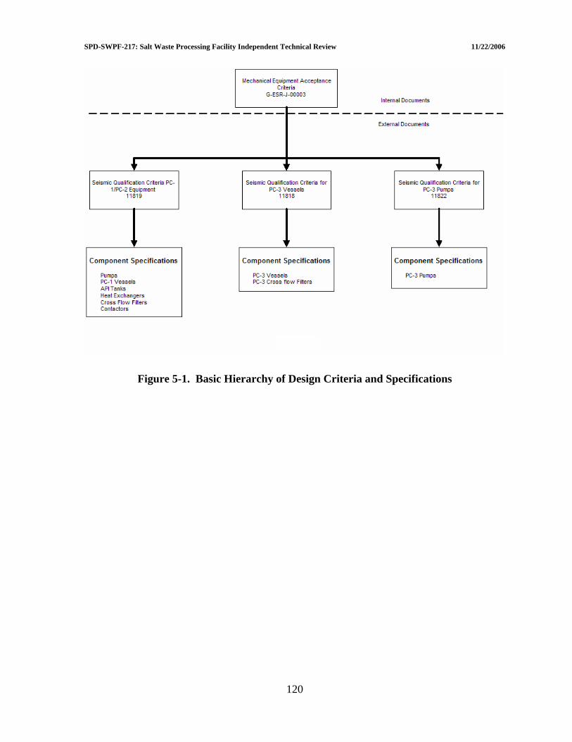
SPD-SWPF-217: Salt Waste Processing Facility Independent Technical Review 11/22/2006
Figure 5-1. Basic Hierarchy of Design Criteria and Specifications
120

SPD-SWPF-217: Salt Waste Processing Facility Independent Technical Review 11/22/2006
121
Vessel Shell and Nozzle Qualification Criteria: Load Combinations
PM (7)
PL+PB (7)
PL+PB+Q (7)
PL+PM+Q+F (7)
Compressive Load
Notes
PD S - - - - PD + D + DML S 1.5S 3S - Meet UG-
23(b) (1), (4),
Pmax + D + DML + SSEl + PSlosh
1.2S 1.8S 3S - Meet UG-23(b)
(1), (4), (5)
T - - 3s - - (2), (6)PNO + D + DML + T
S 1.5S 3S Sa (7) - (3), (4), (6)
Notes (1) “Q” Stress excludes the effects of thermal expansion but considers the effects of discontinuities (2) “Q” Stress includes only the effects of thermal expansion (3) “Q” Stress includes the effects of both thermal expansion and discontinuities (4) DML = Design Mechanical Loads; it shall include the effects of vibration and APA operation loads as applicable. (5) PSlosh is the total pressure due to fluid sloshing during a DBE as calculated per ASCE 4-98 Section 3.5.4. (6) Thermal loads, T, shall include the effects of content heat-up and the cooling jackets. (7) Detailed definition of these terms can be found in ASME BPVC, Section VIII, Division 2, Appendix 4. Support Qualification Criteria: Load Combinations Acceptance Criteria Notes D + DML + TH AISC 325, “Specification for Structural Steel Buildings –
Allowable Stress Design”, June 1, 1989 (1)
D + DML + TH + SSE1 + FSlosh
AISC 325, “Specification for Structural Steel Buildings – Allowable Stress Design”, June 1, 1989 with the 1.33 increase permitted per Section A5.2
(1), (2)
Notes (1) DML = Design Mechanical Loads; it shall include the effects of vibration and APA operation loads as applicable. (2) FSlosh is the total load (forces and moments) due to fluid sloshing during a DBE as calculated per ASCE 4-98
Section 3.5. Anchorage Load Combinations: Load Combinations Notes D + DML + TH (1) D + DML + TH + SSE1 + FSlosh (1), (2) Notes (1) DML = Design Mechanical Loads; it shall include the effects of vibration and
APA operation loads as applicable. (2) FSlosh is the total load (forces and moments) due to fluid sloshing during a
DBE as calculated per ASCE 4-98 Section 3.5.
Figure 5-2. Suggested Sample Format and Detail for Criteria Specification in Procurement and Qualification Specifications
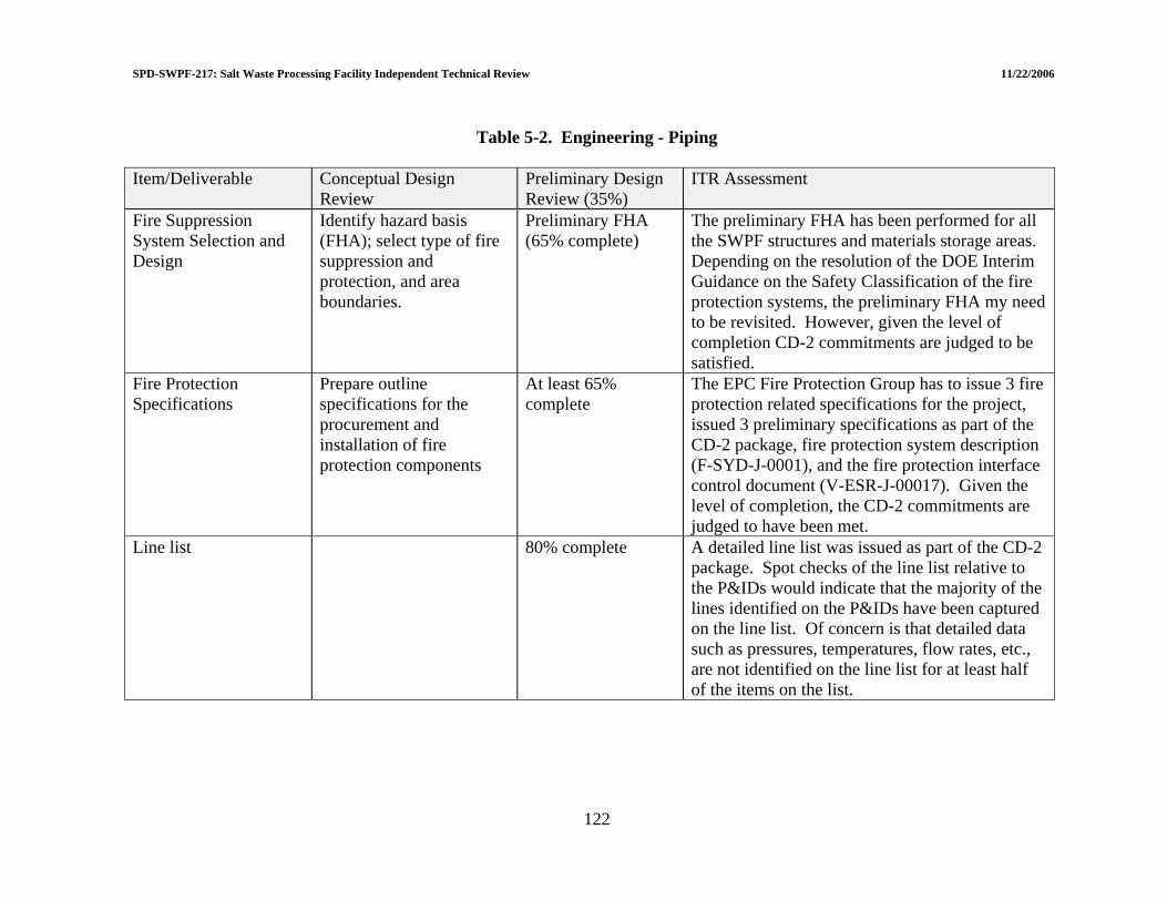
SPD-SWPF-217: Salt Waste Processing Facility Independent Technical Review 11/22/2006
Table 5-2. Engineering - Piping
Item/Deliverable Conceptual Design
Review Preliminary Design Review (35%)
ITR Assessment
Fire Suppression System Selection and Design
Identify hazard basis (FHA); select type of fire suppression and protection, and area boundaries.
Preliminary FHA (65% complete)
The preliminary FHA has been performed for all the SWPF structures and materials storage areas. Depending on the resolution of the DOE Interim Guidance on the Safety Classification of the fire protection systems, the preliminary FHA my need to be revisited. However, given the level of completion CD-2 commitments are judged to be satisfied.
Fire Protection Specifications
Prepare outline specifications for the procurement and installation of fire protection components
At least 65% complete
The EPC Fire Protection Group has to issue 3 fire protection related specifications for the project, issued 3 preliminary specifications as part of the CD-2 package, fire protection system description (F-SYD-J-0001), and the fire protection interface control document (V-ESR-J-00017). Given the level of completion, the CD-2 commitments are judged to have been met.
Line list 80% complete A detailed line list was issued as part of the CD-2 package. Spot checks of the line list relative to the P&IDs would indicate that the majority of the lines identified on the P&IDs have been captured on the line list. Of concern is that detailed data such as pressures, temperatures, flow rates, etc., are not identified on the line list for at least half of the items on the list.
122
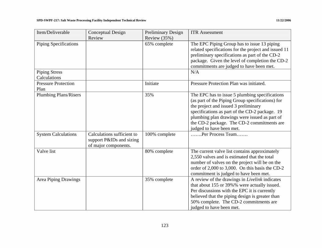
SPD-SWPF-217: Salt Waste Processing Facility Independent Technical Review 11/22/2006
Item/Deliverable Conceptual Design Review
Preliminary Design ITR Assessment Review (35%)
Piping Specifications 65% complete The EPC Piping Group has to issue 13 piping related specifications for the project and issued 11 preliminary specifications as part of the CD-2 package. Given the level of completion the CD-2 commitments are judged to have been met.
Piping Stress Calculations
N/A
Pressure Protection Plan
Initiate Pressure Protection Plan was initiated.
Plumbing Plans/Risers 35% The EPC has to issue 5 plumbing specifications (as part of the Piping Group specifications) for the project and issued 3 preliminary specifications as part of the CD-2 package. 19 plumbing plan drawings were issued as part of the CD-2 package. The CD-2 commitments are judged to have been met.
System Calculations Calculations sufficient to support P&IDs and sizing of major components.
100% complete …….Per Process Team…….
Valve list 80% complete The current valve list contains approximately 2,550 valves and is estimated that the total number of valves on the project will be on the order of 2,000 to 3,000. On this basis the CD-2 commitment is judged to have been met.
Area Piping Drawings 35% complete A review of the drawings in Livelink indicates that about 155 or 39%% were actually issued. Per discussions with the EPC it is currently believed that the piping design is greater than 50% complete. The CD-2 commitments are judged to have been met.
123

SPD-SWPF-217: Salt Waste Processing Facility Independent Technical Review 11/22/2006
124
Item/Deliverable Conceptual Design Review
Preliminary Design Review (35%)
ITR Assessment
Piping Isometrics Initiate A few piping isometrics were available for review. The CD-2 commitments are judged to have been met.

SPD-SWPF-217: Salt Waste Processing Facility Independent Technical Review 11/22/2006
5.3 HEATING, VENTILATION, AND AIR CONDITIONING (HVAC) The ITR review of the SWPF HVAC Systems focused on the design of the Central Process Area (CPA) confinement ventilation system and the Alpha Finishing Area (AFF) confinement ventilation system. The CPA ventilation system is comprised of multiple ventilation systems including the Process Building Ventilation System (PBVS), and Laboratory Portion of the Process Building ventilation system, the Process Vessel Ventilation System (PVVS), and the Pulse Jet Mixer Ventilation System (PMVS). The Control Room ventilation system and the Cold Chemical Area ventilation system were not reviewed. The Control Room ventilation system was not reviewed because it is a standalone non-zoned system and no habitability requirements have been identified for this area at this stage of design. The Cold Chemicals Area ventilation system was not reviewed because it is a standalone, non-zoned, industrial system with no nuclear requirements. A summary of ITR findings for HVAC is included in Table 5-3. 5.3.1 Maturity of Design 5.3.1.1 Summary of response to LOI III.b.2 “Does the maturity of the HVAC (Building ventilation, Process Vessel Vent System [PVVS], and Process Mixer Vent System [PMVS]) design support 35% completion status, as defined in Salt Processing Division procedure SPD-SWPF-002?” The maturity of the HVAC design supports 35% completion status (CD-2) as defined in SPD-SWPF-002. The HVAC design deliverables for CD-2 are shown in Table 5-3. 5.3.1.2 Confinement design Consistent with DOE interim guidance on safety integration (July 18, 2006, Memorandum “Interim Guidance on Safety Integration into Early Phases of Nuclear Facility Design”, Dr. I.R. Triay, DOE-EM, to Distribution), the CPA and AFF ventilation systems are designated as safety significant (SS) confinement systems for worker protection. The CPA ventilation system is classified as SS for those portions that ventilate primary confinements (i.e., the process tanks, process cells, laboratory gloveboxes, and laboratory hot cells). For the PVVS, the SS classification begins at the Air Dilution inlets to the process tanks and extends from the tank exhaust pipes, through the air cleanup trains, HEPA filters, and fans until the fan discharge duct taps into the main PBVS exhaust header. For the PBVS, the SS classification begins at inlet HEPA filters to the process cells and extends from the cell exhaust ducts through the HEPA filters and fans until the fan discharge duct exits the Process Building structural boundary. In the laboratory areas, the SS classified portion begins at inlet HEPA filters to the gloveboxes and extends from the glovebox exhaust ducts, through the hot cell areas, scrubbers and HEPA filters until the tie in back to the PBVS exhaust header. The AFF is classified as SS for those portions of the exhaust that exit the process vessel area and extends through the HEPA filters and fans until the fan discharge exits the AFF structural boundary.
125
SPD-SWPF-217: Salt Waste Processing Facility Independent Technical Review 11/22/2006
The safety related portions of the CPA and AFF ventilation systems are being designed to meet guidance for the design of nuclear confinement ventilation systems as promulgated in DOE Design Guide (DOE G420.1B[53]) and in the Nuclear Air Cleaning Handbook (DOE-HDBK-1169-2003[54]). The Standards/Requirements Identification Document (S/RID) and Design Criteria Database (DCD) for HVAC systems include the appropriate design, installation, and test standards from DOE G420.1B and DOE-HDBK-1169-2003. The system designs incorporate zone differential pressures and cascade airflows to ensure contamination stays in designated contamination areas and that air discharges are filtered prior to discharge to the environment. The systems have instrumentation necessary for monitoring system performance and for alarming abnormal or unacceptable operation. The systems are designed with redundant fans and filtration equipment to ensure continued system operation during maintenance evolutions and for the majority of process upsets. The systems are not designed to provide active ventilation during or following a seismic event because they are not designed to Performance Category 3 structural criteria (PC-3) and they are not provided with a safety related power source. Area of Concern 5.3-41: Intended functions of the CPA confinement system to contain hazardous materials and monitor hazardous material releases may be compromised due to General Service classification where exhaust duct header exits the CPA boundary and discharges through the exhaust stack. In PDSA, it appears that there may be HEPA filter failures from causes such as an explosion event. In particular, this portion of the exhaust header is at positive pressure and runs through occupied non-radiological maintenance areas in the Eastern Facility Support Area. Recommendation AC 5.3-41: The confinement function of the exhaust duct header for mitigating a hazardous material release should be verified. 5.3.1.3 HVAC air flow and control drawings Drawings for building ventilation zones and airflow and control are completed for all the HVAC Systems. Airflow directions, zone differential pressures, I&C, and functional classification of SSCs are consistent with the confinement design described in 5.3.1.2 above. 5.3.1.4 HVAC layout drawings Layout drawings showing general arrangement of HVAC major equipment and elevation of ducting have been generated for all building areas. The drawings are consistent or better than the 65% required for the CD-2 deliverable. 5.3.1.5 HVAC supports drawings and calculations At present, this activity has not started. The first deliverable for detailed duct design, including isometric drawings, duct fabrication sections and details, and duct support drawings and calculations is due at the CD-3 65% design review. The path forward on this
126
SPD-SWPF-217: Salt Waste Processing Facility Independent Technical Review 11/22/2006
activity is not fully developed and there may be schedule conflicts. Section 14.16 of the Balance of Plant BOD, seems to imply this activity may be performed in whole or part by a subcontract. If the intent is perform this work by subcontract, such as the duct design, construction, and installation subcontract at WTP Project, acceptance test requirements and functional test requirements (ATRs/FTRs) for ducting need to be developed to support completion of duct related specifications. As discussed in Section 5.3.1.7 below, development of HVAC ATRs/FTRs has not started which in turn impacts the development of HVAC Specifications. 5.3.1.6 HVAC calculations HVAC calculations for developing flow rates and sizing equipment are complete for all HVAC SSCs. In general, the calculations identified relevant open items and the open items can be managed without significant impact. Suggested Improvement 5.3-42: Functional classification assignments on some calculations are not consistent with functional classifications described in source documents and shown on HVAC Airflow and Control Drawings. It is suggested that the EPC verify calculation functional classifications and correct as required. 5.3.1.7 Acceptance Test Requirements/Functional Test Requirements (ATRs/FTRs) At present this activity has not started. The first deliverable for ATRs/FTRs is for 65% completion at the CD-3 65% design review. Development of ATRs/FTRs is required to support on-going development of HVAC specifications as described in Section 5.3.1.8 below. 5.3.1.8 HVAC specifications Most HVAC specifications that will be required have been identified for development and are in preliminary draft status. In general, draft specifications lack consistency in approach and level of detail. To ensure pedigree of safety related portions of the HVAC systems, system performance criteria (i.e., allowable leakage, structural design pressure, etc.) and vendor acceptance tests (i.e., visual inspections, and structural capability and pressure decay tests) need to be identified consistent with ASME/ANSI N509[55] and N510[56] and/or ASME/ANSI AG-1[57]. Functional classifications assigned to some of the draft specifications need to be corrected for consistency with functional classifications described in source documents and shown on HVAC Airflow and Control Drawings. Many of the draft specifications are either missing or have inconsistent vendor QA program requirements.
127
SPD-SWPF-217: Salt Waste Processing Facility Independent Technical Review 11/22/2006
128
5.3.2 Performance Category Design Designations 5.3.2.1 Summary of response to LOI III.b.1(ii) - Adequacy of PC-3 and PC-1 HVAC
Design As detailed on the HVAC Air Flow and Control drawings[58], the design of all HVAC SSCs is performance category PC-1 except for portions of the PVVS which are seismic PC-3 in the dark cells. The PC-3 portions of the PVVS include the Air Dilution piping for tank inlet air flow and exhaust ventilation piping from the tank outlet through the first isolation valve outside of the process cell. The PC-3 classification of the PVVS piping in the dark cell ensures piping will maintain its’ integrity and a portable air mover could be set up outside the cells following a seismic event, if required. The SWPF ventilation systems and building structures are integral parts of the overall building confinement system. During process upset events, the integrity and leak-tightness of the PC-3 CPA structure may help ensure continued operability of the PBVS to maintain negative differential pressures for confinement. In the current PDSA, the ITR was not able to determine the operability requirements of the AFF ventilation system during process upset events. Suggested Improvement 5.3-43: For the AFF, the integrity and leak-tightness of the PC-1 building structure may impact continued operability of the ventilation system to maintain negative differential pressures for contamination control during process upset events such as high winds, or a breach of the structure. It is suggested that the confinement system requirements of the AFF structures and ventilation system should be addressed in more detail during development of PDSA.
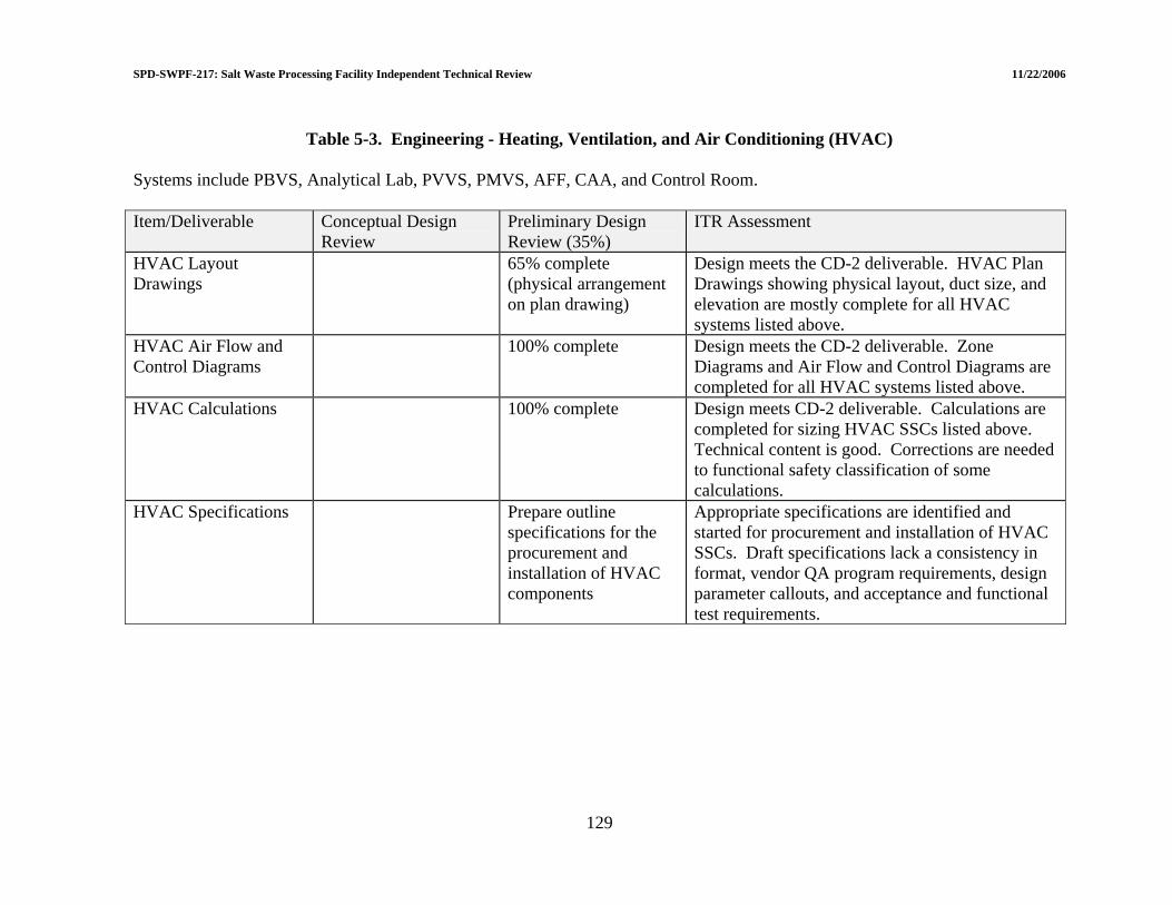
SPD-SWPF-217: Salt Waste Processing Facility Independent Technical Review 11/22/2006
129
Table 5-3. Engineering - Heating, Ventilation, and Air Conditioning (HVAC)
Systems include PBVS, Analytical Lab, PVVS, PMVS, AFF, CAA, and Control Room. Item/Deliverable Conceptual Design
Review Preliminary Design Review (35%)
ITR Assessment
HVAC Layout Drawings
65% complete (physical arrangement on plan drawing)
Design meets the CD-2 deliverable. HVAC Plan Drawings showing physical layout, duct size, and elevation are mostly complete for all HVAC systems listed above.
HVAC Air Flow and Control Diagrams
100% complete Design meets the CD-2 deliverable. Zone Diagrams and Air Flow and Control Diagrams are completed for all HVAC systems listed above.
HVAC Calculations 100% complete Design meets CD-2 deliverable. Calculations are completed for sizing HVAC SSCs listed above. Technical content is good. Corrections are needed to functional safety classification of some calculations.
HVAC Specifications Prepare outline specifications for the procurement and installation of HVAC components
Appropriate specifications are identified and started for procurement and installation of HVAC SSCs. Draft specifications lack a consistency in format, vendor QA program requirements, design parameter callouts, and acceptance and functional test requirements.

SPD-SWPF-217: Salt Waste Processing Facility Independent Technical Review 11/22/2006
5.4 ELECTRICAL DESIGN A summary of ITR findings regarding electrical design is presented in Table 5-4. 5.4.1 Maturity of Electrical Design 5.4.1.1 Summary of response to LOI III.c.1 “Although the electrical design generally trails the other disciplines, is the electrical portion of the design sufficiently mature to define all major components (e.g., transformers) as well as sufficient electrical capacity to provide for future expansion?” The level of maturity of the electrical system is in excess of the 35% design point. In many cases the level of detail in design (such as grounding, lighting, receptacles) is well in advance of what is expected at this stage of the project. All of the major electrical equipment has been defined and physically located. However, as outlined below, further evaluation of the electrical capacities of the system is needed. 5.4.1.2 Electrical power system feeds To increase the reliability of the Electrical Power System[59] two redundant sources of power to feed the system are provided. These two feeds are rated at 13.8 kilovolt (kV) and are derived from two separate 115 kV grid connections. One 13.8 kV power source enters the SWPF via isolating switch ELNA-SW-101 on pole 062G, the other via isolating switch ELNA-SW-102 on pole 062G-B. The power feeds from these isolating switches travel to their respective 13.8 kV switchgears, which are located in the northwest portion of the SWPF, via two separate underground duct banks. There is also a provision for SRS personnel to route 13 kV power via a sectionalizing switch (ELNA-SW-103) which is connected to both 13.8 kV systems upstream of isolating switches ELNA-SW-101 and ELNA-SW-102. ELNA-SW-103 is normally open when SWPF is in operation. Under normal operating conditions approximately half of the SWPF electrical load is fed from 13.8 kV power feeder A and the other half from 13.8 kV power feeder B. It is intended that when any 13.8kV feeder is out of service, then the other picks up the total load. Calculation E-CLC-J-00028 Rev A1 9/8/06 “Maximum Electrical Power Service Demand Study” indicates that the maximum electrical demand of SWPF is 6,435 kilovolt-ampere (kVA) at .89 power factor. If the power from 13.8 kV feeder A is unavailable then the total power i.e., 6,435 kVA for SWPF must be fed from 13.8 kV feeder B. However, at the present time the overhead electrical system that conveys power to isolating switch ELNA-SW-102 can only handle approximately 5,000 kVA. Area of Concern 5.4-42: The overhead electrical system upstream of ELNA-SW-102 cannot handle the plant load when 13.8 kV feeder “A” is not available. Recommendation AC 5.4-42: Redesign the overhead electrical system that conveys 13.8 kV power to the SWPF via isolating switch ELNA-SW-102 so that the maximum
130

SPD-SWPF-217: Salt Waste Processing Facility Independent Technical Review 11/22/2006
demand of 6,435 kVA can be accommodated. This change will also solve the voltage drop problem that exists. Section 2.0 “Open Items” of the above referenced calculation (E-CLC-J-00028) states that calculation will be revised again at the 90% deliverable stage. Due to the importance of this information, it is not appropriate to wait for the 90% deliverable stage before revising the calculation. Suggested Improvement 5.4-44: It is suggested that calculation E-CLC-J-00028 be revised when there are significant load changes or when operating conditions are more defined so that the maximum electrical demand information can be kept current. A schedule for regular updates is also suggested. The reliability of the electrical power system depends to a large degree on the reliability of the power feeds that supply power to the system. Each power feed is run in a separate duct bank and, within the duct bank, in an individual duct. A vulnerability occurs when the feeders enter the manholes where they can be commingled with other 13.8 kV feeders; this could potentially cause damage to the power feeders, if any of them ruptured under fault conditions and started a fire. Technical Issue 5.4-10: The 13.8 kV power feeds are vulnerable to damage where they pass through the manholes. Recommendation TI 5.4-10: Separate to the greatest extent possible the power feeds in the manholes (PMH-1A, PMH-1B, PMH-1C, PMH-2A, PMH-2B, and PMH-2C) from the other 13.8 kV cables and rack them accordingly. Provide some means of fire protection for these power feeds; as a minimum wrap each power feed from the point of entry to the point of exit with fire retardant tape. Revise drawings (E-ER-J-00141, E-E1-J-00033, E-E1-J-00034) accordingly with this information. 5.4.1.3 Evaluation of the electrical power system The Electrical Power System is powered by two separate 13.8 kV feeds from the SRS network (see 5.4.1.2 above). There are basically two independent and redundant electrical systems each powered by a 13.8 kV feeder and each supplying approximately half the plant electrical loads. Under normal plant conditions there are no electrical connections between these two systems. Upon loss of either feed nothing happens automatically. A decision has to be made by the operator as to the cause of the problem and a deliberate action is taken, if deemed appropriate, to connect both systems at the 13.8 kV level via key lockable switches. There is also a provision to connect, via key lockable switches, both systems at the 480 volt switchgear level. Since there is only one 13.8 kV feed to the Administration Building a loss of a particular feeder (the feeder entering SWPF via isolating switch ELNA-SW-102) will result in a loss of power to this building.[60] The power can be restored to this building when cross connections are made at the 13.8 kV levels or when the 13.8 kV feeder is active again.
131

SPD-SWPF-217: Salt Waste Processing Facility Independent Technical Review 11/22/2006
Suggested Improvement 5.4-45: A loss of power to the Administration Building can occur if 13.8 kV feeder “B” is inactive. It is suggested that the EPC document the fact that a loss of power to the Administration Building can occur if 13.8 kV feeder “B” is inactive and that this be added to the document System Number 1000 Electrical, System Design Description E-SYD-J-00001 and other appropriate documents. The 13.8 kV systems feed transformers which then deliver power to 480V switchgear which supplies power to the Motor Control Centers. There are no electrical loads supplied directly by the 13.8 kV systems. To establish ratings for the 13.8 kV electrical system equipment, a calculation[61] was performed by the EPC. This calculation, E-CLC-J-00005 Rev B dated 9/8/06, “Power Distribution Short Circuit Study”, had input from another calculation, calculation E-CLC-J-00026 Rev A dated 9/8/06, “Transmission Line Short Circuit study”. Calculation E-CLC-J-00026 had as design input technical information (Attachment #16) dictated from a telephone conversation with IS&D personnel. Transmitting critical design input information by telephone contact is contrary to the requirement outlined in Quality Assurance Plan, Deliverable: 7.6, V-QP-J-00001 Rev 1 dated 7/27/06, Section 1.4.1 “Request for Information”[62]. The electrical design input information needs to be formally requested in accordance with the Quality Assurance Plan and should include the following (for both tap off points) in addition to that which is shown in Attachment 16:
• Maximum/minimum voltages.
• Planned expansions that could have an effect on the maximum fault currents.
• Maximum kVA load that can be supplied to the SWPF electrical systems with the present configuration of overhead lines.
• History on the reliability of service e.g., outages and interruptions, voltage dips,
voltage and frequency variations, fault clearing times. Suggested Improvement 5.4-46: Electrical design input from SRS has not always been obtained through the process outlined in the Quality Assurance Plan. It is suggested that the EPC request the SRS electrical design input information be provided in accordance with the Quality Assurance Plan. It is further suggested that the EPC replace Attachment 16 in calculation E-CLC-J-00026 with the written response to the request. An overloaded condition or a near overload condition for transformers was uncovered in calculation E-CLC-J-00004 Rev B dated 9/8/06 “Power Distribution Load Flow Study”[63]. It is recognized that conservative loads were inputs to the calculation computer program and diversity was not strictly applied which led to these situations. Transformers XFMR-101 and XFMR-102 were shown to be overloaded by 15.73%. The overload and near overload conditions exist when one 13.8 kV switchgear and associated transformers are called upon to take on the load of the total plant 480 V loads. This scenario can occur when there is a loss
132
SPD-SWPF-217: Salt Waste Processing Facility Independent Technical Review 11/22/2006
of particular 13.8 kV switchgear or a failure of transformer(s) connected to this switchgear. However, the overload identified should not be ignored considering the project stage and the 20% increase that needs to be added to the capacity for future load growth. Also the SWPF electrical loads have a high harmonic content due to a large number of Variable-Frequency Drives. Since high harmonic content can affect the sizing of transformers there needs to be a calculation performed to analyze the situation (see Suggested Improvement 5.4-49). Area of Concern 5.4-43: Transformers XFMR-101, XFMR-102, XFMR-103, XFMR-104, XFMR-106, and XFMR-107 are overloaded or are at near overload conditions in the scenario where a 13.8 kV switchgear or associated transformers are out of service. Recommendation AC 5.4-43: Re-evaluate transformer XFMR-101, XFMR-102, XFMR-103, XFMR-104, XFMR-106, and XFMR-107 sizing with considerations given to the required 20% spare capacity and the validity of the required loads identified at this stage of the project. Transformer size increases or the use of forced cooling of existing transformers are possible solutions if overloads are confirmed. Section 16.1.1 of the document Balance of Plant Basis of Design, (P-DB-J-00004, Revision B), states that the 13.8 kV switchgear and 480 V Motor Control Centers have a minimum of 20% spare capacity for future load growth. There was no mention of spare capacity for 480 V switchgears or transformers other than the statement in Section 16.3, “Electrical Operability Considerations” which states “Power transformers are sized for the largest combination of continuous loads plus an allowance for short-time or intermittent loads”. It is also not clear when the 20% spare capacity is applied, is it at the 35% stage, 100% stage or what? Suggested Improvement 5.4-47: It is suggested that the EPC specify in P-DB-J-00004 spare capacities for 480 V switchgears and power transformers. Also, it should be specified at what point in time in the project the spare capacities apply. In addition, it is suggested that the single line diagrams should show the spares and the physical drawings, where appropriate, should show the additional space occupied due to the spare capacity. In addition to normal power, there is a Standby Diesel Generator (SDG) which supplies power to essential loads when the normal power is lost. The SDG start is initiated when a loss of voltage is sensed at any one of the four Automatic Transfer Switches (ATSs) (ATS-201, ATS-202, ATS-203, and ATS-204). Loading of the SDG is controlled by the Distributed Control System. The SDG has the capability of running for four days at 100% load. There is also a provision to connect up a portable generator to the 480 V-standby switchgear in the event that maintenance is being performed on the SDG or if there is failure of the SDG. A load bank for the periodic testing of the SDG is also provided. Section 16.1.2 of the document Balance of Plant Basis of Design, (P-DB-J-00004, Revision B), states that the SDG is sized to provide 20% spare capacity to allow for any potential load growth. It could make a big difference in the size of the SDG depending on when the 20% spare capacity is applied. An overloaded condition for the SDG was uncovered in calculation E-CLC-J-00004 Rev B, dated 9/8/06, “Power Distribution Load Flow Study”. It
133

SPD-SWPF-217: Salt Waste Processing Facility Independent Technical Review 11/22/2006
is recognized that conservative loads were inputs to the calculation computer program and diversity was not strictly applied which led to the SDG being shown as overloaded by approximately 15%. However, the overload identified should not be ignored considering the project stage and the 20% increase that needs to be added to the capacity for future load growth. Area of Concern 5.4-44: The Standby Diesel Generator can reach an overloaded condition. Recommendation AC 5.4-44: Specify in document P-DB-J-00004 at what point in time in the project the 20% spare capacity for the SDG applies. Re-evaluate the SDG sizing with considerations given to the required 20% spare capacity and the validity of the required loads identified at this stage of the project. In a worst case scenario (a tornado hit), both the normal power equipment (transformers/ switchgears) and the Standby Diesel Generator and associated equipment could be disabled. Because it may not be possible to connect the portable generator to the Diesel Generator 480V switchgear at that time, the plant could be without another source of power. Suggested Improvement 5.4-48: In a situation where a tornado disables both the normal and standby electrical equipment, it may not be possible to connect the portable generator as another source of power. It is suggested that the EPC evaluate the situation to determine if other appropriate measures need to be developed to address the possibility of not being able to utilize the portable generator as a source of power. It is further suggested that the EPC document the outcome of the evaluation. 5.4.1.4 Calculations to support issued design When design information is issued, calculations addressing the designs are the appropriate method to support the design that is being issued. Suggested Improvement 5.4-49: Calculations have not been performed to support all issued electrical design. It is suggested that the EPC perform calculations to support the issued designs as follows: harmonic content, grounding grid, duct ban/manholes, and lighting. 5.4.1.5 Underground activities The Electrical design consists of structures and commodities which will be placed “underground” as part of the overall design of SWPF. Examples are: duct banks and manholes, grounding grids and cathodic protection components. Some of these will not be accessible once construction proceeds. Part of the grounding grid, e.g., would be placed under the building structure and therefore would not be accessible once the building foundation is poured. In addition, there may be conduit systems embedded in the concrete of the building foundation.
134

SPD-SWPF-217: Salt Waste Processing Facility Independent Technical Review 11/22/2006
Grounding grid calculation needs to be performed so that the grid configuration and conductor sizes can be established. The information from the calculation will identify the grounding grid and its ties to the other grounding already shown on existing drawings. The calculation will also serve as a confirmation of the adequacy of the grounding shown on the many grounding drawings which have already been issued. Note: There is an EPC Civil Group restraint at this time. They have an action to provide soil resistivity information to the EPC Electrical Group to allow the calculation to proceed. See Suggested Improvement 5.4-49. Very detailed drawings e.g., E-ER-J-00141, E-E1-J-00033, and E-E1-J-00034, have been issued showing locations of duct banks and manholes[64], however, there are no calculations performed to show the basis of the design. Calculations need to be performed to address:
• Thermal rating of cables and the potential effect on duct spacing and duct sizes within a duct bank.
• The spacing of the manholes which are established to facilitate the cable pulling
process and the change in direction of duct banks. Considerations such as direction of cable pull, cable conductor tensions, cable sidewall pressure, and minimum cable bending radius need to be factored into the calculations.
• The minimum bending radius of duct stub-ups e.g., at switchgears, transformers and
overhead line poles. Considerations such as direction of cable pull, cable conductor tensions, cable sidewall pressure, and minimum cable bending radius need to be factored into the calculations.
• The minimum size of manhole cover on manholes to facilitate cable pulling operation
so that the minimum cable bending radius is not violated. The calculation will confirm whether the 32-inch diameter manhole cover is adequate. See Suggested Improvement 5.4-49.
Suggested Improvement 5.4-50: Only ducts for 13.8 kV cables have been shown in duct banks. It is suggested that the EPC re-evaluate the duct banks need for ducts of other cables besides 13.8 kV e.g., 480 V power or control. Also, which ducts are to be used for construction cables should be established. Suggested Improvement 5.4-51: There are neither profiles for duct banks nor coordinates for manholes. It is suggested that this be coordinated with the EPC Civil Group to establish both the profiles and the coordinates for the duct banks/manholes. Further, it is suggested to add the coordinates of the manholes to the appropriate electrical drawings. There is a need for standby power at the AFF electrical room. At the present time, the plan is to route a conduit system from the main electrical room to the AFF electrical room to convey the necessary power cables. This is a relatively long run which will be partly embedded in the concrete foundation of the building. Considerations outlined above for the duct bank/manhole design should also be applied to this design.
135

SPD-SWPF-217: Salt Waste Processing Facility Independent Technical Review 11/22/2006
Suggested Improvement 5.4-52: The conduit system to convey standby power from the main electrical room to the AFF electrical room is not shown. The EPC should develop the conduit system for the AFF standby power and show it on the relevant drawings. While most of the lightning protection conductors are located above ground, there are connections to the underground grounding system. The drawings, e.g., E-EG-J-00047, E-GE-J-00048, are very detailed. However, the designs are not supported by a calculation. Also, in the document entitled Balance of Plant Basis of Design (P-DB-J-00004, Revision B), Section 16.2.5 states specifically that the Dissipation Array System that is employed at DWPF will not be used. Suggested Improvement 5.4-53: There are no calculations to support the lightning protection designs. Since DWPF has operated very successfully over the years with the lightning protection that they installed, it is suggested that the EPC give serious consideration needs to be given to applying this system on SWPF. In any case, the EPC should perform the necessary calculations to support the system chosen. 5.4.1.6 Design criteria A document is needed to clearly establish criteria so that there is consistency of application among the engineers and designers. At this time, no document exists for the EPC Electrical Group. Other disciplines have similar documents to a Design Criteria document e.g., the “Structural Acceptance Criteria” P-ESR-J-00002[65] and the “Mechanical Equipment Acceptance Criteria” G-ESR-J-00003[35]. Without a Design Criteria document, it is an individual responsibility to interpret the codes and standards based on their experiences and knowledge which can lead to inconsistencies in the design. Suggested Improvement 5.4-54: There is no Electrical Design Criteria document. It is suggested that the EPC prepare an Electrical Design Criteria document to include the criteria applicable to this project. Examples of criteria to be included: voltages and tolerances at each bus and at each load, the fact that all uninterrupted power supply cables are to be run in conduits, illumination levels for each room/area, and spare electrical capacities for electrical equipment and how applied. 5.4.1.7 Lighting calculations Lighting calculations are required to support the lighting layouts already issued. These calculations are required to back up the spacing/height and size/type of light fixture chosen. These calculations should support the final layout configurations. See Suggested Improvement 5.4-49.
136

SPD-SWPF-217: Salt Waste Processing Facility Independent Technical Review 11/22/2006
5.4.2 Cable Tray Layouts 5.4.2.1 Summary of response to LOI III.c.2 “Are basic cable tray layouts sufficiently developed to provide an accurate construction cost estimate?” The cable tray systems shown in the 35% package will support an accurate construction estimate when conservative contingency factors are applied to address an evolving design. 5.4.2.2 Evaluation of cable tray systems The philosophy adopted is to maximize the use of tray and to use conduit for end runs and for those areas that are heavily congested e.g., piping, HVAC ductwork, etc. Judgments were made as to the size of the cable trays necessary. Neither the locating dimensions nor elevations of the trays are shown on the cable tray layout drawings[66]. At this stage of the project, the objective is to preserve space for cable trays by including the information on the 3D model. The model will also be used to show 3 inch and larger conduits; however there is no plan to show banks of conduits on the model. Two separate tray systems are shown, one for power cables and the other for instrument and control cables. There is no criterion that requires separation of redundant cable systems. The cable tray systems are still evolving with the design. Changes in locations and sizes are occurring e.g., a major run of instrumentation tray has been changed from a 12 inch to a 24 inch. The 3D model is being used to resolve interferences where in a number of cases the relocation of the tray has been the result or a tray has gone from a single tray to two smaller trays at different elevations to avoid interference. Suggested Improvement 5.4-55: It is suggested that the EPC develop criteria for the cable tray system. The suggested cable tray criteria should address: trays for power and control cabling (only power trays are shown now); separation of redundant cables within a tray or the use of separate trays; the handling of “large” and “small” cables within tray; the potential of damage due to “two over one” situations (e.g., the damage of both redundant cables); the requirement of showing locating dimensions and elevations on drawings. The criteria developed may have an effect on the cable tray layouts. 5.4.2.3 Cable and raceway scheduling The document Design Documentation Administrator for the Salt Waste Processing Facility, (SPD-SWPF-002, Revision 1[67]) indicated in Appendix B (Electrical) that the Plant Data Management System (PDMS) is used for cable and raceway scheduling. At the present time, the project is using a manual method, not the automated PDMS. The manual method, while feasible, is very labor intensive and limits the availability of timely reports. Error detection is more difficult as is construction support and tracking. The project is reviewing the
137

SPD-SWPF-217: Salt Waste Processing Facility Independent Technical Review 11/22/2006
138
possibility of utilizing an automated system. It should be noted that the PDMS is the standard program at SRS. Suggested Improvement 5.4-56: An automated system is not being utilized for circuit and raceway scheduling. It is suggested that the EPC evaluate the need for an automated system for the circuit and raceway scheduling with consideration been given to the SRS standard program (PDMS).

SPD-SWPF-217: Salt Waste Processing Facility Independent Technical Review 11/22/2006
Table 5-4. Engineering – Electrical Design Item/Deliverable Conceptual Design
Review Preliminary Design Review (35%)
ITR Assessment
Cable Schedule (PDMS)
N/A
Cathodic Protection Drawings
N/A
Communication Drawings
Preliminary Progress supports all of the projects activities at the stage of the project.
Conduit Schedule (PDMS)
Preliminary (Sample) The automated Plant Data Management System (PDMS) is not being utilized. Manual methods are being used instead.
Coordination Study Drawings
N/A
Electrical Equipment Sizing Drawings
Initiate, major components of the distribution system
Refine Sizing of electrical equipment is shown on both single line drawing and equipment location drawings which fully supports the 35% stage of the project.
Grounding Drawings Develop grounding conductor layout (to support installation of foundations etc.)
Project is well advanced in the development of grounding drawings. For this stage of the project, the number of drawings is in excess of what is normally expected.
Grounding Grid Calculations
Develop to estimate the number of ground rods/grid size
Grounding grid calculations have not been performed.
Heat Tracing Drawings N/A Interconnection/ Wiring Diagrams
N/A
139
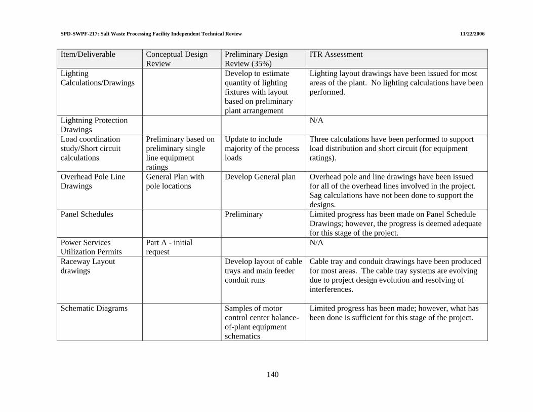
SPD-SWPF-217: Salt Waste Processing Facility Independent Technical Review 11/22/2006
Item/Deliverable Conceptual Design Review
Preliminary Design ITR Assessment Review (35%)
Lighting Calculations/Drawings
Develop to estimate quantity of lighting fixtures with layout based on preliminary plant arrangement
Lighting layout drawings have been issued for most areas of the plant. No lighting calculations have been performed.
Lightning Protection Drawings
N/A
Load coordination study/Short circuit calculations
Preliminary based on preliminary single line equipment ratings
Update to include majority of the process loads
Three calculations have been performed to support load distribution and short circuit (for equipment ratings).
Overhead Pole Line Drawings
General Plan with pole locations
Develop General plan Overhead pole and line drawings have been issued for all of the overhead lines involved in the project. Sag calculations have not been done to support the designs.
Panel Schedules Preliminary Limited progress has been made on Panel Schedule Drawings; however, the progress is deemed adequate for this stage of the project.
Power Services Utilization Permits
Part A - initial request
N/A
Raceway Layout drawings
Develop layout of cable trays and main feeder conduit runs
Cable tray and conduit drawings have been produced for most areas. The cable tray systems are evolving due to project design evolution and resolving of interferences.
Schematic Diagrams Samples of motor control center balance-of-plant equipment schematics
Limited progress has been made; however, what has been done is sufficient for this stage of the project.
140

SPD-SWPF-217: Salt Waste Processing Facility Independent Technical Review 11/22/2006
141
Item/Deliverable Conceptual Design Review
Preliminary Design Review (35%)
ITR Assessment
Single line Diagrams Preliminary based on conceptual process design and loads.
Revise to reflect well defined process loads and issue to support procurement specifications
A very complete set of detailed single line diagrams have been issued. These will support all of the project activities at this stage of the project.
Hazardous Classification Drawings
Preliminary All areas of the plant where there is a hazardous classification, a drawing has been produced.
Underground Utilities Duct Banks/Manholes
Develop duct bank route, profile and location of manholes (to support installation of yard piping systems)
An extensive duct bank and manhole system has been shown on drawings. Manhole coordinates and duct bank profile have yet to be developed.
Equipment Location Plans
Preliminary Drawings showing equipment locations for all areas of the plant have been issued. Very detailed information on locations has been provided.
Receptacle Plans Preliminary Receptacle drawings have been issued for most areas of the plant. The drawings are more than adequate for this stage of the project.
Overhead Line Sag Calculations
N/A
Electrical Specifications
Prepare outline specifications for the procurement and installation of electrical components
Twelve engineered equipment specifications and fourteen non-engineered equipment specifications have been issued. These support the activities that are taking place on the project at this time.

SPD-SWPF-217: Salt Waste Processing Facility Independent Technical Review 11/22/2006
5.5 INSTRUMENTATION AND CONTROL (I&C) A summary of ITR Findings for Instrumental and Control is presented in Table 5-5. 5.5.1 Maturity of I&C Design 5.5.1.1 Summary of response to LOI III.d.1 “Although the I&C design generally trails the other disciplines, is the I&C design sufficiently mature to define all major components (e.g., number of Input/Output) as well as sufficient surplus capacity to provide for future expansion?” The level of maturity of the Instrumentation and Control (I&C) systems is in excess of the 35% design point. All necessary major equipment has been identified and in most cases the specific vendor supplied equipment identified[68]. The number of input/output points and the number of control loops have been specified to include all currently identified plus 25% spare capacity. In addition, the equipment and technology being employed on the project allows for easy expansion of the system. 5.5.1.2 System architecture Positive Finding 5.5-10: The system architecture for both the Distributed Control System and Safety Instrumented System will result in highly reliable systems. All of the necessary information required to operate the plant and monitor the performance will be available where it is needed in a timely manner. The basic architecture of the systems should be allowed to evolve with the increase in capability of products supplied in the process control industry. The equipment currently specified should easily accommodate this evolution. 5.5.1.3 Design technology The incorporation of redundant controllers, bus technology, smart instrumentation, and intelligent actuators will result in a highly reliable system. This approach of using the best available technology in the industry today will result in a very cost effective system. The maintenance and calibration cost will be minimal and impacts on system operation due to instrument and control actuator issues should be non-existent. 5.5.1.4 Equipment As indicated in the technology section, the equipment currently specified is excellent equipment. Some of this equipment is the current SRS standard equipment. The project should take advantage of all of the SRS standard equipment where applicable. The standard equipment agreements will result in a price advantage for the project and minimize the maintenance and spare parts requirements issues once the plant is in operation.
142
SPD-SWPF-217: Salt Waste Processing Facility Independent Technical Review 11/22/2006
Suggested Improvement 5.5-57: SRS has adopted site standard equipment that have existing procurement contracts. The project has selected the site standard Distributed Control System but there are many other site standard components which should be investigated for use on the project. 5.5.1.5 Software quality assurance Area of Concern 5.5-45: The SWPF Project Procedure PP-GN-1017, Computer Software Management[69], does not apply to I&C systems. There are no other procedures which address software quality assurance for I&C systems. This will be an issue for the project based on the history of the Defense Nuclear Facility Safety Board (DNFSB) and DOE on projects over the last ten years. Recommendation AC 5.5-45: It is recommended that a set of procedures and practices be developed that specifically address software quality assurance for I&C systems. An area of particular importance in these procedures is Configuration Management of I&C Software and testing for unintended functions. All software used for design purposes should follow PP-GN-1017. The development of these procedures should consider the DOE and DNFSB initiatives in this area since 2002. These procedures should be developed quickly so that rework can be minimized. 5.5.1.6 Design process 5.5.1.6.1 Design procedures While the current state of the design is judged to be very good and the discussions about how the design will progress in the future indicate the appropriate intent, there are no written procedures that direct how the work will be done, verified, and documented. Also, this is particularly important with software and the current DOE software quality assurance requirements. Suggested Improvement 5.5-58: It is suggested that the EPC develop a set of procedures and practices for the I&C systems which may include the software quality assurance issues identified above and the design criteria and requirements that apply. 5.5.1.6.2 Safety significant instrumented systems Area of Concern 5.5-46: The defined design process for Safety Significant Instrumented Systems (SSIS) is that specified in ANSI/ISA 84.00.01-2004[70]. This design approach defines a failure on demand requirement for a system which is based on the probability of occurrence and consequence of a particular event. This is an accepted approach in DOE complex.
143

SPD-SWPF-217: Salt Waste Processing Facility Independent Technical Review 11/22/2006
The current approach for SSIS on this project is to procure equipment with certified failure on demand capability that would support a Safety Integrity Level (SIL) II system. While this equipment is probably what is needed or more, the approach is not defendable and certainly does not apply ANSI/ISA 84.00.01-2004. Recommendation AC 5.5-46: It is recommended that the calculations indicated in ISA 84.00-01-2004 be performed for each SSIS and that the system failure on demand with the selected equipment be determined. This would provide the documentation required to defend the designed systems. 5.5.1.6.3 Functional classification Suggested Improvement 5.5-59: SWPF Project Procedure PP-NS-5501, Functional Classification Methodology[71], defines five functional classifications and the criteria for each. In the Balance of Plant Basis of Design document, a classification “important to safety” is mentioned. It is suggested that this term be removed from the Balance of Plant Basis of Design document and replaced with the appropriate one of the five functional classifications. The project has decided to functionally classify instrumentation which monitors system operating conditions which are initial condition inputs to safety analysis as safety significant. This approach is counter to the general approach in the nuclear industry. If the intent of the arbitrary classification was to ensure the reliability of the instrumentation, the desire could be satisfied by specifying a reliability requirement for the instrumentation. The functional classification process classifies systems and components that must function post event as safety class or safety significant depending on the consequences of the event. Since the instrumentation in question does not have to operate post event, they would not be classified as safety significant. Thus, the functional classification of the initial condition monitoring instrumentation should be changed from safety significant. Suggested Improvement 5.5-60: The functional classification of the instrumentation used to monitor parameters which are initial conditions for the safety analysis is not consistent with nuclear industry practice. It is suggested that the functional classification be done consistent with the nuclear industry practice. This should result in the lowering of the current functional classification. 5.5.1.7 Control philosophy The current plant is to employ standard Project Information Document (PID) control for all control loops. Although it is early in the design process, consideration should be given to evaluating controls requirements for each loop using the plant simulator. This type of study would require the plant models, but not the final simulator implementation. These types of studies could identify the need for other types of control approaches.
144

SPD-SWPF-217: Salt Waste Processing Facility Independent Technical Review 11/22/2006
5.5.1.8 Plant simulator The project includes a dynamic plant simulator to be used for operator training, procedure development, and initial design of control loop parameters. This part of the project is in the initial phase of design. The simulation efforts at SRS and WTP should be reviewed before selecting a simulator platform and developing the system models. The WTP simulator development has developed comprehensive material properties for the Hanford tank waste. In addition, WTP went through a very comprehensive simulator platform evaluation before selecting the platform. This evaluation should be reviewed and feedback on the performance of the simulator obtained before the SWPF Simulator platform is selected. Suggested Improvement 5.5-61: It is suggested that the EPC review plant simulator efforts at WTP and SRS before selecting the simulator platform, the mathematical models, and the physical properties database. Suggested Improvement 5.5-62: SRS has been evaluating the performance of contactors as part of a waste processing process for several years. Part of this evaluation included the development of a mathematical model of a contactor. This project should obtain and evaluate the SRS model before developing the simulator models. 5.5.1.9 Human factors engineering Suggested Improvement 5.5-63: The project has committed to applying NUREG-0700[72] to the design of the man machine interface. SRS has developed a computer program that can identify the applicable requirements from NUREG-0700 for a specific project. SWPF should obtain this software from SRS. SRS has developed display standards for the Delta V Distributed Control System that comply with NUREG-0700 requirements. SWPF should employ these display standards where practical. As part of the development of the man machine interface for the Distributed Control System which is consistent with the human factors engineering standard, SRS has developed a graphics library. The project should obtain this library.
145
SPD-SWPF-217: Salt Waste Processing Facility Independent Technical Review 11/22/2006
5.5.1.10 Seismic switch Area of Concern 5.5-47: The current design includes a switch that detects a seismic event of a defined magnitude and initiates protective actions. The existence of a reliable switch is questionable. SRS has been evaluating switches for this type of an event for the past few years. SWPF should obtain the result of the SRS evaluations. A design approach which may improve the reliability of seismic detection would be to include the site seismic monitoring network and multiple locations of seismic detectors in the plant. Recommendation AC 5.5-47: SRS has been looking at such switches for several years. The project should obtain the SRS information for evaluation of applicability to the project. 5.5.2 Cable Tray Layouts 5.5.2.1 Summary of response to LOI III.d.2 “Are basic cable tray layouts sufficiently developed to provide an accurate construction cost estimate?” The utilization of bus technology in the SWPF I&C design makes this issue much less critical than in conventional designs. As previously mentioned, the choice of bus technology for this project is excellent. At this stage of the design there is sufficient information to develop an accurate construction cost estimate. 5.5.3 Valve Procurement Area of Concern 5.5-48: The present design includes a number of plug valves with operators which must be seismically qualified. The I&C organization is responsible for writing the procurement specification for these valves with appropriate input on the applicable response spectrum and anticipated supports. The vendor is expected to supply a qualified valve. This particular valve design is non-conventional and the quantities required may not interest the dominant valve manufacturers in supplying the valves. The supplier will have to be a certified NQA-1 supplier. The uncertainty associated with procurement of these valves represents a significant risk to the project. Recommendation AC 5.5-48: There are a number of plug valves with operators and manually operated valves of the same basic design which must be seismically qualified. These valves should be combined in a single procurement to enhance the ability to attract qualified vendors.
146
SPD-SWPF-217: Salt Waste Processing Facility Independent Technical Review 11/22/2006
147
5.5.4 Impact of NQA-1 The requirements of NQA-1 need to be addressed in the development of the recommended procedures for I&C systems. 5.5.5 Operations Participation in Design Suggested Improvement 5.5-64: In several discussions with the EPC I&C organization, issues such as automated operating procedures which require operations input were identified. Many of the decisions in the design of the plant control and information system have a significant impact on plant operations. The design of the man-machine interface, operational sequencing and other Distributed Control System operation functions require the participation of Operations. It is suggested that the EPC involve the plant operations staff in the design of the I&C system.
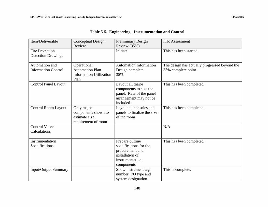
SPD-SWPF-217: Salt Waste Processing Facility Independent Technical Review 11/22/2006
Table 5-5. Engineering - Instrumentation and Control Item/Deliverable Conceptual Design
Review Preliminary Design Review (35%)
ITR Assessment
Fire Protection Detection Drawings
Initiate This has been started.
Automation and Information Control
Operational Automation Plan Information Utilization Plan
Automation Information Design complete 35%
The design has actually progressed beyond the 35% complete point.
Control Panel Layout Layout all major components to size the panel. Rear of the panel arrangement may not be included.
This has been completed.
Control Room Layout Only major components shown to estimate size requirement of room
Layout all consoles and panels to finalize the size of the room
This has been completed.
Control Valve Calculations
N/A
Instrumentation Specifications
Prepare outline specifications for the procurement and installation of instrumentation components
This has been completed.
Input/Output Summary Show instrument tag number, I/O type and system designation.
This is complete.
148

SPD-SWPF-217: Salt Waste Processing Facility Independent Technical Review 11/22/2006
Item/Deliverable Conceptual Design Review
Preliminary Design ITR Assessment Review (35%)
Instrument Data Sheet Show tag number, service description, P&ID number, available process data and other salient features of instrument for a sample system
This is complete.
Instrument Index Include instrument tag numbers, P&IDs, instrument type, location and service description.
This is complete.
Instrument Installation Detail
N/A
Instrument Location Drawing
Show instruments, major instrument racks and field panels. Piping drawings to locate in-line devices may not be available to show other instruments.
This is complete.
Instrument Rack Drawing
N/A
Level Setting Diagram N/A Logic Diagram Overall logic
description for Safety Class systems
Samples to present basic system operation in conjunction with P&ID.
Logic diagrams will not be a deliverable for this project.
Loop Diagram N/A Set Point Index
Initiate This is complete.
149
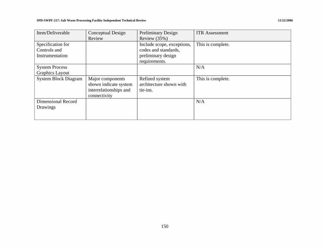
SPD-SWPF-217: Salt Waste Processing Facility Independent Technical Review 11/22/2006
150
Item/Deliverable Conceptual Design Review
Preliminary Design Review (35%)
ITR Assessment
Specification for Controls and Instrumentation
Include scope, exceptions, codes and standards, preliminary design requirements.
This is complete.
System Process Graphics Layout
N/A
System Block Diagram Major components shown indicate system interrelationships and connectivity
Refined system architecture shown with tie-ins.
This is complete.
Dimensional Record Drawings
N/A
SPD-S
WPF-217: Salt Waste Processing Facility Independent Technical Review 11/22/2006
151
5.6 LIMITED CONSTRUCTION 5.6.1 Maturity of Limited Construction CD-3 Design 5.6.1.1 Summary of response to LOI III.e.1 “Does the scope identified for the Limited Construction has a completed design and a CD-3 level construction cost estimate?” The ITR had insufficient information to review to answer this LOI. 5.6.2 Scope for CD-3A 5.6.2.1 Summary of response to LOI III.e.2 “Does the scope identified for CD-3A provide a reasonable optimization between schedule improvement and risk reduction?” The ITR had insufficient information to review to answer this LOI. 5.7 OPERATIONS, MAINTENANCE, AND DECONTAMINATION AND
DECOMMISSIONING (D&D) A summary of ITR findings related to D&D are presented in Table 5-6. 5.7.1 Operations, Maintenance, and D&D Design Futures 5.7.1.1 Summary of response to LOI III.f.1 “Does the design include features which will adequately support future operation, maintenance and D&D of the facility?” The documents provide very specific plant layout requirements, which are very beneficial to have early in the design, and the design will adequately support future operations and maintenance activities. The planning for commissioning is very thorough and shows excellent knowledge of the responsibilities and the sequence of commissioning activities. The facility design is compatible with the ability to deactivate, decontaminate as needed, and demolish the facility at the completion of its mission. A negative finding regarding the laboratory hot cell has resulted in a recommendation that it be lined with stainless steel to the maximum degree practicable to facilitate D&D.

WPF-217: Salt Waste Processing Facility Independent Technical Review 11/22/2006
152
Table 5-6 Engineering – Operations/Maintenance/D&D Item/Deliverable Conceptual Design
Review Preliminary Design Review (35%)
ITR Assessment
Demolition and Removal Drawings
See discussion of the review approach in subsection 5.7.1.3
Preliminary Equipment removal pathways during the operating lifetime are sufficient for D&D. With regard to building demolition drawings, the ITR opinion is such are unnecessary. Instead, the review of the ability to demolish is addressed in topics in Table 5-7.
SPD-S
SPD-SWPF-217: Salt Waste Processing Facility Independent Technical Review 11/22/2006
5.7.1.2 Operations and Maintenance 5.7.1.2.1 Operations Requirements Document The Operations Requirements Document (P-ESR-J-00011.4) states that the document provides the basis that will be used by the EPC to integrate operability, maintenance and testability requirements into the SPF design. The Operations Requirements Document also provides the framework for development of P-ESR-J-0004 [SWPF Commissioning Strategy]. The Operations and Requirements Document and the Commissioning Strategy were reviewed for adequacy at the CD-2 state of design. The review determined the documents were complementary and consistent. As stated in the Introduction [Section 1] of the document there is a need to verify the Documented Safety Analysis requirements. The other testing objectives are also well founded. The overview provided in Section 4 lays out a well conceived listing and sequence of activities from construction testing through operations. Specific positive points are: the plans to develop a Design Requirements Matrix to link acceptance criteria to the design basis, and plans to identify the tests which assure the design requirements will be met. The sequence of activities identified enables plan to be in place in a timely fashion. The recognition of the value of a readiness self-assessment before the start of cold commissioning is excellent for commissioning planning. Hot tie-ins are not planned until the completion of cold commissioning. Plans to use low radioactivity before high radioactivity are well-conceived. Sections 6 and 10 through 13 provide specific facility layout requirements that are “recommended”. The recommendations are through, complete and well thought-out. However, the tendency to use ”recommended” makes it unclear what are the true “requirements”. Although most of these recommendations are included in the Design Criteria database, there are significant omissions in the Design Criteria Database. The commissioning provisions, which are to be “verified by testing” required in the design for Reliability, Availability, Maintainability, and Inspectability are both thorough and reasonable. Positive Finding 5.7-11: Including Operation and Maintenance early in the design phase is excellent, and recognition of the need to operate within the Documented Safety Analysis provides assurance of completeness of the preliminary design for CD-2. These are examples of a good operation and maintenance philosophy for the project, and provide assurance of the completion of Preliminary Design. Sections 6 and 7 provide excellent and detailed plans for Operation, Maintenance and Staffing Plans. This good practice of involvement of Operations/Commissioning staff should continue throughout the remainder of design.
153
SPD-SWPF-217: Salt Waste Processing Facility Independent Technical Review 11/22/2006
5.7.1.2.2 Commissioning Strategy Review of the document[8] determined a very detailed and thorough strategy has been developed based on the Operations Requirement Document and the preliminary design documents. 5.7.1.3 Decontamination and Decommissioning 5.7.1.3.1 Review approach The D&D lines of inquiry have been conducted based on the reviewer’s separate compilation of design features that are friendly to D&D. That compilation has been used to create the list of review topics in Table 5-7. This review has been conducted with the following perspective:
• Decommissioning activities for almost any type of facility are well within the technological state-of-the-art. The major impact for complications resulting from insufficient consideration during design is the cost of (a) gaining access to high radiation areas and (b) dealing with high levels of contamination.
• Designing for the operational mission of the facility is a higher priority than
accommodating ease of decommissioning. The recommendations here should be considered as preferable design practices when they can be accommodated without compromising the primary design objectives.
• This review assumes that demolishing the facility will be the final phase of
decommissioning. It is noted that in-situ decommissioning is being considered for some of the reactors at SRS and if that is accepted, such a mode would also be feasible for this facility. However, in-situ decommissioning is not stated as a design basis. Therefore, demolition is basis for this review.
At the 35% design stage, it is concluded that design features and intent well support decommissioning with regard to the ability to deactivate, decontaminate (to the degree necessary for dose reduction) when the facility is to be demolished. This overall conclusion has been reached based on the areas addressed and conclusions stated in Table 5-7. With regard to the stated 35% deliverable for Demolition and Removal Drawings[73], the following is noted:
• Equipment removal pathways designed for use during the operating lifetime are sufficient for D&D.
• The ITR opinion is that building demolition drawings are unnecessary during design.
The method for demolition will be chosen far in the future and will be based on the then extant contamination conditions of the facility and demolition methods available. Instead, the review of the ability to demolish is addressed in the topics in Table 5-7.
154

SPD-SWPF-217: Salt Waste Processing Facility Independent Technical Review 11/22/2006
155
The ability to demolish the hot cell in the laboratory is made complex because two of the hot cell walls are integral to the building structure and are on an upper level of the building. This will make for a difficult removal situation if the walls cannot be well decontaminated prior to demolition. We have also been told in presentations that it is the intent to only partially line the hot cell with stainless steel and to use coatings for the upper portions. Designing the hot cell to be lined with stainless steel over as much of the surface area as is practical will reduce the difficulty when it comes time to remove it. This will provide for more effective decontamination with high pressure water prior to removal. In addition, the attachment of the liner to the walls should be designed so that it can be separated with reasonable effort to the degree that its structural integrity and ability to decontaminate the interior are not compromised. Suggested Improvement 5.7-65: It is suggested that the EPC line the interior floor, walls, and ceiling of the laboratory hot cell with stainless steel to the maximum degree practicable. It is also suggested that the EPC add requirements on design of piping systems for flushing and on coatings for decontamination into the appropriate basis of design documents. Suggested Improvement 5.7-66: Dose reduction design features for normal operations are also useful for D&D. This includes pipe flushing, coatings on surfaces to enhance the ability to decontaminate, and avoidance of crud traps. These subjects are addressed in the ALARA review procedure and are apparently subject of design practice in some cases. The EPC should develop written design requirements or guidance related to flushing, coatings, and avoidance of crud traps. Suggested Improvement 5.7-67: For future D&D planning, the EPC should consider developing a comprehensive photographic record during construction and cold operations, that captures features which will not be visible or accessible in the future. This would include, e.g., video and/or photographs of the rebar for foundations and heavy walls before pouring concrete, the underground excavation before backfilling after the lower part of the building is in place, and inside all the dark cells. This Suggested Improvement can be implemented after CD-3A is reached and when construction commences.

SPD-SWPF-217: Salt Waste Processing Facility Independent Technical Review 11/22/2006
Table 5-7. Review of the Design for Decommissioning Topic Subjects Addressed Conclusions Yard and Exterior Spaces Yard Areas Space for cranes Sufficient yard space should be available for
mobile cranes and lifting equipment There is sufficient area in what is now the temporary construction area west of the main building as well as east of the main building and south of the admin building.
Space for Waste Management Space should be available in the immediate area of the facility for waste operations
Parking lots will suffice.
Access for large equipment Access will also be required heavy-duty trucks, demolition excavators, and earthmovers
J Area Northern access road satisfies this.
Underground Tunnels and Vaults Avoid excessive placement of large below-grade tunnels and vaults
There are none that are covered by slabs.
Roofs and Siding Roof and siding materials should not contain asbestos containing materials (ACM)
There is no ACM in the design.
Structures and Interior Spaces Interior Spaces Space for cleanup & waste processing equipment
Where are interior locations where decontamination and local HVAC can be staged?
Space for waste management and equipment removal
Where is there space for loading and staging of waste containers?
Sufficient space for this purpose is in the 70 ft x 80 ft area encompassing the east truck bay and offices. In addition, an area of 70 ft x 200 ft can be potentially used that combines the truck bay, offices and maintenance area in the east end of the building.
Use of Hazardous Materials Do the design requirements prohibit asbestos, mercury containing switches, polychlorinated biphenyl (PCB) light ballasts, lead-based paint, PCB-based paint, and other similar materials
Random check of liquid filled transformers specs confirmed prohibition of PCBs. Wall panel specs prohibited asbestos fibers. Equipment and materials with these types of constituents are generally no longer available.
156

SPD-SWPF-217: Salt Waste Processing Facility Independent Technical Review 11/22/2006
Topic Subjects Addressed Conclusions Placement of Large or Heavy Equipment Above first floor Is there large or heavy equipment above the
grade floor that would be difficult to remove? Most equipment can be removed and with the 20-ton crane lowered to the 100 ft level. With the exception of large tanks (addressed later), equipment such as the contactor motors and internals can be removed and the contactor housings can be or size-reduced for removal.
Removal through walls or ceilings/floors
Will the building be constructed around heavy equipment and if so are there panels or shield plugs by which it can be removed.
See later discussion of tanks.
Removal pathways Is there a clear removal pathway for large fans and pumps?
Yes; fans and pumps on the 116 ft level are designed for replacement.
In contaminated areas Is all large electrical distribution equipment not in contaminated areas?
There is no large distribution or switchgear equipment within contaminated areas.
Shield Walls & Floors Ability to decontaminate Rooms that are likely to be surface
contaminated to significant levels should have a removable liner or coating on floors and wall.
We were verbally informed that “epoxy coatings for decontamination would be used on all wall and floor surfaces in the process areas and on the ceilings in the alpha area as well.” However, this could not be found in any design requirements that would ensure consistency among designers.
Wall thickness Concrete walls greater than 4 feet thick up to the first floor above grade and 3 feet thick on upper floors present challenges for conventional demolition equipment.
Walls generally do not exceed these dimensions. There is a limited 4 ft thick wall as part of the IT server room next to the control room. However, it is limited and will not be an issue for demolition. Demolition of the 3 ft walls in the central core of the facility will be a challenge, however, it is not as severe as many other DOE facilities.
157
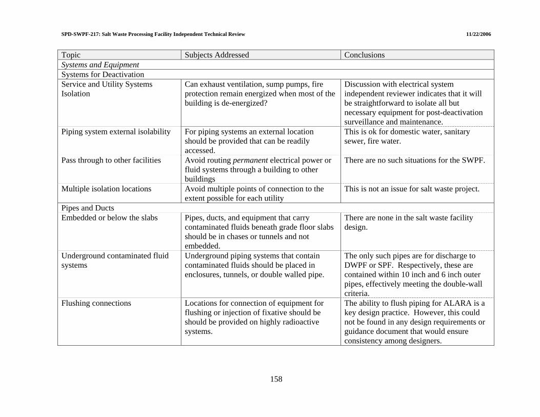
SPD-SWPF-217: Salt Waste Processing Facility Independent Technical Review 11/22/2006
Topic Subjects Addressed Conclusions Systems and Equipment Systems for Deactivation Service and Utility Systems Isolation
Can exhaust ventilation, sump pumps, fire protection remain energized when most of the building is de-energized?
Discussion with electrical system independent reviewer indicates that it will be straightforward to isolate all but necessary equipment for post-deactivation surveillance and maintenance.
Piping system external isolability For piping systems an external location should be provided that can be readily accessed.
This is ok for domestic water, sanitary sewer, fire water.
Pass through to other facilities Avoid routing permanent electrical power or fluid systems through a building to other buildings
There are no such situations for the SWPF.
Multiple isolation locations Avoid multiple points of connection to the extent possible for each utility
This is not an issue for salt waste project.
Pipes and Ducts Embedded or below the slabs Pipes, ducts, and equipment that carry
contaminated fluids beneath grade floor slabs should be in chases or tunnels and not embedded.
There are none in the salt waste facility design.
Underground contaminated fluid systems
Underground piping systems that contain contaminated fluids should be placed in enclosures, tunnels, or double walled pipe.
The only such pipes are for discharge to DWPF or SPF. Respectively, these are contained within 10 inch and 6 inch outer pipes, effectively meeting the double-wall criteria.
Flushing connections Locations for connection of equipment for flushing or injection of fixative should be should be provided on highly radioactive systems.
The ability to flush piping for ALARA is a key design practice. However, this could not be found in any design requirements or guidance document that would ensure consistency among designers.
158
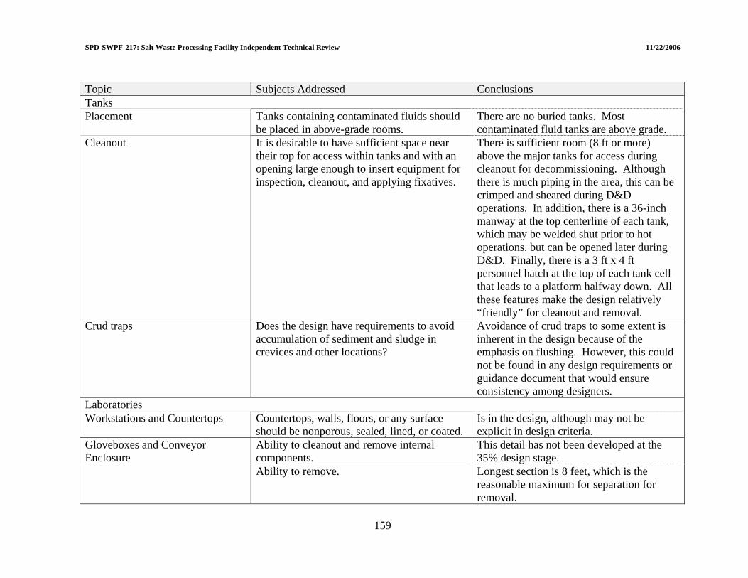
SPD-SWPF-217: Salt Waste Processing Facility Independent Technical Review 11/22/2006 Topic Subjects Addressed Conclusions Tanks Placement Tanks containing contaminated fluids should
be placed in above-grade rooms. There are no buried tanks. Most contaminated fluid tanks are above grade.
Cleanout It is desirable to have sufficient space near their top for access within tanks and with an opening large enough to insert equipment for inspection, cleanout, and applying fixatives.
There is sufficient room (8 ft or more) above the major tanks for access during cleanout for decommissioning. Although there is much piping in the area, this can be crimped and sheared during D&D operations. In addition, there is a 36-inch manway at the top centerline of each tank, which may be welded shut prior to hot operations, but can be opened later during D&D. Finally, there is a 3 ft x 4 ft personnel hatch at the top of each tank cell that leads to a platform halfway down. All these features make the design relatively “friendly” for cleanout and removal.
Crud traps Does the design have requirements to avoid accumulation of sediment and sludge in crevices and other locations?
Avoidance of crud traps to some extent is inherent in the design because of the emphasis on flushing. However, this could not be found in any design requirements or guidance document that would ensure consistency among designers.
Laboratories Workstations and Countertops Countertops, walls, floors, or any surface
should be nonporous, sealed, lined, or coated. Is in the design, although may not be explicit in design criteria.
Ability to cleanout and remove internal components.
This detail has not been developed at the 35% design stage.
Gloveboxes and Conveyor Enclosure
Ability to remove. Longest section is 8 feet, which is the reasonable maximum for separation for removal.
159

SPD-SWPF-217: Salt Waste Processing Facility Independent Technical Review 11/22/2006
160
Topic Subjects Addressed Conclusions Ability to decontaminate. The laboratory hot cell is the primary area
of concern. Decontamination capability is included in the design for use during the operating life cycle, which will aid in decommissioning.
Hot cells
Ability to demolish. Two of the hot cell walls are integral to the building structure and are on an upper level of the building. This will make for a difficult removal situation if the walls cannot be well decontaminated prior to demolition. It would be preferable to have a cell liner on these walls that would not be an integral structural part of the building; that is, can be reasonably separated.

SPD-SWPF-217: Salt Waste Processing Facility Independent Technical Review 11/22/2006
5.8 RISK MANAGEMENT 5.8.1 Engineering Risks 5.8.1.1 Summary of response to LOI III.g.1 “Have all engineering risks been identified and addressed; do any remain?” The ITR has determined that all engineering risks have not been identified and addressed. The EPC has been receptive to recommendations identifying risks and plans action to minimize or remove the risks. Some examples are provided below. 5.8.1.2 Valve procurement risk The current design includes a number of manual and automatic valves of a unique design which must be seismically qualified. The risk of not being able to procure these valves to the required specifications is judged to be significant. 5.8.1.3 Undissolved solids There is no clear definition of the properties of the undissolved solids coming in with the waste. A better characterization is needed for the undissolved solids properties coming in with the waste. These properties should be issued to determine an input property envelop, and actions need to be taken within equipment limitations to handle material outside the defined envelop. 5.8.1.4 Vessel/tank design During the review of the PFDs/P&IDs, the design only provided for vacuum protection with a relief valve on the common header. Although redundant relief valves are provided, this is considered insufficient protection for the number of vessels and tanks in the dark cell. The piping design required a special layout for maintenance of the relief valves which adds cost. Lessons learned from tank and vessel failures when subject to vacuum caused by pumping from the tanks demonstrated that additional protection is needed. The vessels/tanks should be designed for full vacuum. The additional cost will eliminate a large economic risk.
161
SPD-SWPF-217: Salt Waste Processing Facility Independent Technical Review 11/22/2006
5.8.2 Risks of Conversion from ISO-9001 to NQA-1 5.8.2.1 Summary of response to LOI III.g.2 “Have risks resulting from the conversion from ISO-9001 to NQA-1 been adequately addressed?” No, the assessment to date is not adequate. The EPC conducted a gap analysis to determine what parts of their existing ISO-9001 program needed to be modified. The results of this gap analysis led to recommendations to change over 30 procedures. This gap analysis did not include an analysis of the impact of the changes on design work that has been performed. The EPC is committed to bringing in a QA resource to lead an effort to evaluate the impact of changes on existing work. The QA resource is expected to start by mid-November. This evaluation will involve looking at the changes made to procedures and seeing what impact there is on previous work. A specific area that needs to be examined is in the area of specifications that are marked safety significant (SS) and invoke ASME NQA-1. There is also inconsistency in the specification of quality assurance requirements. Some documents have a detailed appendix on quality assurance requirements and some do not. Some specifications call out detailed Software Quality Assurance requirements and other do not. The specifications need to be updated to incorporate NQA-1 and ensure consistent quality assurance requirements. 5.9 REFERENCES (1). S-RCP-J-00001, Revision 1, Standard/Requirements Identification Document.
Parsons, Aiken, South Carolina. June 26, 2006. (2) P-SPC-J-00001, Revision 0, Feed Strategy and Product and Secondary Waste
Specification. Parsons, Aiken, South Carolina. December 22, 2004. (3) P-SPC-J-00002, Revision 0, Functional Specification. Parsons, Aiken, South
Carolina. January 11, 2005. (4) P-DB-J-00003, Revision 0, Process Basis of Design. Parsons, Aiken, South Carolina.
June 1, 2006. (5) P-ESR-J-00011, Revision 0, Operations Requirements Document. Parsons, Aiken,
South Carolina. July 11, 2006. (6) P-DB-J-0002, Revision D, Salt Waste Processing Facility Project Design Criteria
Database. Parsons, Aiken, South Carolina. September 12, 2006. (7) SPD-SWPF-002, Revision 1, Design Documentation Administration for the Salt
Waste Processing Facility. U.S. Department of Energy-Savannah River Operations Office. August 2006.
(8) P-ESR-J-00004, Revision 1, Commissioning Strategy. Parsons, Aiken, South Carolina. September 13, 2006.
(9) P-DRR-J-0002, Process Flow Diagrams [As listed in Livelink (CD-2) Critical Decision – 2 Package (OUO), Attachment A – 35% Design Package, Book 1: PDR Design Control Drawings, 1.0 Process Flow Diagrams]
162
SPD-SWPF-217: Salt Waste Processing Facility Independent Technical Review 11/22/2006
(10) P-DRR-J-0002, Piping and Instrument Diagrams [As listed in Livelink (CD-2) Critical Decision – 2 Package (OUO), Attachment A – 35% Design Package, Book 1: PDR Design Control Drawings, 2.0 Piping and Instrumentation Diagrams]
(11) P-DRR-J-0002, General Arrangement Drawings [As listed in Livelink (CD-2) Critical Decision – 2 Package (OUO), Attachment A – 35% Design Package, Book 1: PDR Design Control Drawings, 4.0 General Arrangement Drawings]
(12) P-ESR-J-00003, Revision 0, Operations Assessment and Tank Utilization Models. Parsons, Aiken, South Carolina. January 19, 2006.
(13) P-PCD-J-00001, Revision 0, Design Process Description. Parsons, Aiken, South Carolina, July 13, 2005.
(14) S-NCS-J-00001, Revision 9, Nuclear Criticality Safety Evaluation: Salt Waste Processing Facility Operations. Parsons, Aiken, South Carolina. April 21, 2005.
(15) X-WCP-J-00001, Revision 0, Recommended SWPF Waste Compliance Plan for Transfers to the Defense Waste Processing Facility and the Saltstone Production Facility. Parsons, Aiken, South Carolina. August 24, 2006.
(16) Merrow, E.W. A Quantitative assessment of R&D requirements for solids processing technology, Edward W. Merrow Rand Corporation. 1986.
(17) Merrow, E.W. Linking R&D to problems experience in solids processing Chem Eng Progress pp 14-22. May 1985.
(18) Estimating start up times for solids processing plants. Chem Eng pp 89-92. 1988. (19) Problems and progress in solids processing Chem Innovation pp 35-41. January
2000. (20) Bell, T.A. Challenges in the scale-up of particulate processes – and industrial
perspective Timothy A. Bell (DuPont) Powder Technology pp 60-71. 2005. (21) WSRC-RP-2003-0021, Tritium Facility Test Weld Serial Number(s): 100454.
Washington Savannah River Company, Aiken, South Carolina. June 3, 2003. (22) P-TPL-J-00080, Revision 8, Test Plan: Air Pulse Agitator Pilot–Scale Test. Parsons,
Aiken, South Carolina. May 12, 2005. (23) P-RPT-J-00002, Revision 0, Test Report: Air Pulse Agitator Pilot–Scale Test.
Parsons, Aiken, South Carolina. March 1, 2006. (24) P-DDR-J-0002, Book 6: Calculations, 2.0 Process (M-CLC-J-00061). (25) P-DDR-J-0002, Book 6: Calculations, 2.0 Process (M-CLC-J-00090). (26) P-RPY-J-00003, Draft, CSSX Test Report. Parsons, Aiken, South Carolina. (27) P-TPL-J-00082, Revision 0, Test Plan: Caustic-Side Solvent Extraction Solvent
Carryover Characterization and Recovery Test. Parsons, Aiken, South Carolina. May 6, 2005.
(28) P-TPL-J-00079, Revision 1, Test Plan: Caustic-Side Solvent Extraction Full-Scale Test. Parsons, Aiken, South Carolina. May 3, 2006.
(29) P-TPL-J-00078, Revision 3, Cross-Flow Filter System Full-Scale Test Plan. Parsons, Aiken, South Carolina. June 30, 2006.
(30) P-DRR-J-0002 [As listed in Livelink (CD-2) Critical Decision – 2 Package (OUO), Attachment A – 35% Design Package] Book 5 Specifications
(31) P-DRR-J-0002 [As listed in Livelink (CD-2) Critical Decision – 2 Package (OUO), Attachment A – 35% Design Package] (Process Piping)
(32) F-FHA-J-001, Revision C, Preliminary Fire Hazards Analysis. Parsons, Aiken, South Carolina. April 15, 2005.
163
SPD-SWPF-217: Salt Waste Processing Facility Independent Technical Review 11/22/2006
(33) F-SYD-J-0001, Revision A2, System Number 1300 Fire Detection/Protection. Parsons, Aiken, South Carolina. March 23, 2006.
(34) V-ESR-J-00017, Revision 1, Fire Protection Water System Interface Control Document (ICD-17). Parsons, Aiken, South Carolina. March 16, 2006.
(35) G-ESR-J-00003, Revision 0, Mechanical Equipment Acceptance Criteria. Parsons, Aiken, South Carolina. September 12, 2006.
(36) ASME Boiler and Pressure Vessel Code, Section II, Section V, Section VIII Division 1 and 2, and Section IX, 2001 Edition up to and included the 2002 Addenda. American Society of Mechanical Engineers. June 2002
(37) ASME NQA-1-2004, Quality Assurance Program for Nuclear Facilities. American Society of Mechanical Engineers. January 1, 2004.
(38) IEEE 344 - IEEE Standard 344, IEEE Recommended Practice for Seismic Qualification of Class 1E Equipment for Nuclear Power Generating Stations. Institute of Electrical and Electronics Engineers. 1987 and IEEE Standard P344/D27, IEEE Draft Recommended Practice for Seismic Qualification of Class 1E Equipment for Nuclear Power Generating Stations. Institute of Electrical and Electronics Engineers. 2004.
(39) DOE/EH-0545, Seismic Evaluation Procedure for Equipment in U.S. Department of Energy Facilities. U.S. Department of Energy. March 1997.
(40) ASME QME-1 - ASME QME-1-2002, Qualification of Active Mechanical Equipment Used in Nuclear Power Plants. American Society of Mechanical Engineers. 2002 and “Draft Changes to Section QR and QR-A of ASME QME-1”, approved by ASME Board of Nuclear Codes and Standards, December 2005.
(41) DOE-STD-1020-2002, Natural Phenomena Hazards Design and Evaluation Criteria for Department of Energy. DOE Area NPHZ, January 2002.
(42) ASCE 43-05, Seismic Design Criteria for Structures, Systems, and Components in Nuclear Facilities. American Society of Civil Engineers. January 1, 2005.
(43) ASCE 7-02, Minimum Design Loads for Buildings and Other Structures. American Society of Civil Engineers. January 12, 2002.
(44) WRC-353 – Welding Research Council Bulleting 353, “Position Paper on Nuclear Plant Pipe Supports”, Welding Research Council. May 1990.
(45) IBC-2003, International Building Code 2003, International Code Council. 2002. (46) DOE Interim Safety Guidance Letter; July 18, 2006, Memorandum “Interim
Guidance on Safety Integration into Early Phases of Nuclear Facility Design”, Dr. I.R. Triay, DOE-EM, to Distribution.
(47) G-ESR-J-00003, Revision 0, Mechanical Equipment Acceptance Criteria. Parsons, Aiken, South Carolina. September 12, 2006.
(48) 3016R502004, Revision 1A, Evaluation of SWPF Process Materials, General Atomics, California. September 9, 2005.
(49) American Society of Metals (ASM) “Corrosion Handbook, Volume 13 – Corrosion in Pipelines”, 1989.
(50) Stress-Corrosion Cracking Materials Performance and Evaluation, R.H. Jones, Editor, American Society of Metals, Materials Park, OH. 1992.
(51) Fontana, Corrosion Engineering, Third Edition, McGraw-Hill, Inc. 1986. (52) PP-CM-8004, Revision A2, SWPF MST/Sludge Slurry Piping and Nozzle Erosion
Evaluations Procedure. Parsons, Aiken, South Carolina. September 1, 2006.
164
SPD-SWPF-217: Salt Waste Processing Facility Independent Technical Review 11/22/2006
(53) DOE Order 420.1B, Facility Safety. U.S. Department of Energy. December 22, 2005.
(54) DOE-HDBK-1169-2003, DOE Handbook: Nuclear Air Cleaning Handbook. U.S. Department of Energy. November 2003.
(55) ASME/ANSI-N-509-1989, Nuclear Power Plant Air Cleaning Units and Components with Addenda. American Society of Mechanical Engineers. 1989.
(56) ASME/ANSI-N-510-1989, Testing of Nuclear Air Treatment Systems. American Society of Mechanical Engineers. 1989.
(57) ASME AG-1-2003, Code on Nuclear Air and Gas Treatment. American Society of Mechanical Engineers. 2003.
(58) P-DRR-J-0002 [As listed in Livelink (CD-2) Critical Decision – 2 Package (OUO), Attachment A – 35% Design Package] Book 1: PDR Design Control Drawings, 6.0 HVAC Air Flow and Control Diagram and Book 2: Discipline Drawings, 4.0 HVAC Drawings
(59) P-DRR-J-0002 [As listed in Livelink (CD-2) Critical Decision – 2 Package (OUO), Attachment A – 35% Design Package] Book 2: Discipline Drawings, 5.0 Electrical Drawings
(60) E-SYD-J-00001, Revision A2, System Number 1000 Electrical, System Design Description. Parsons, Aiken, South Carolina. February 28, 2006.
(61) P-DRR-J-0002 [As listed in Livelink (CD-2) Critical Decision – 2 Package (OUO), Attachment A – 35% Design Package] Book 6: Calculations, 5.0 Electrical (E-CLC-J-00005 Rev B, E-CLC-J-00026 Rev A)
(62) V-QP-J-00001, Revision 1, Quality Assurance Plan. Parsons, Aiken, South Carolina. July 27, 2006.
(63) P-DRR-J-0002 [As listed in Livelink (CD-2) Critical Decision – 2 Package (OUO), Attachment A – 35% Design Package] Book 6: Calculations, 5.0 Electrical (E-CLC-J-00004 Rev B)
(64) P-DRR-J-0002 [As listed in Livelink (CD-2) Critical Decision – 2 Package (OUO), Attachment A – 35% Design Package] Book 2: Discipline Drawings, 5.0 Electrical Drawings (E-ER-J-00141, E-E1-J-00033, E-E1-J-00034)
(65) P-ESR-J-00002, Revision 1, Structural Acceptance Criteria. Parsons, Aiken, South Carolina. September 22, 2006.
(66) P-DRR-J-0002 [As listed in Livelink (CD-2) Critical Decision – 2 Package (OUO), Attachment A – 35% Design Package] Book 2: Discipline Drawings, 4.0 HVAC Drawings (Cable tray layout drawings).
(67) SPD-SWPF-002, Revision 1, Design Documentation Administrator for the Salt Waste Processing Facility. U.S. Department of Energy-Savannah River Operations Office. August 2006.
(68) P-DRR-J-0002 [As listed in Livelink (CD-2) Critical Decision – 2 Package (OUO), Attachment A – 35% Design Package, Book 2: Discipline Drawings, 6.0 Instrumentation Drawing; Book 3: PDR Supplement Sheets, 3.0 Instrumentation and Control; and Book 5: Specifications, 4.0 Instrumentation and Control Specifications].
(69) PP-GN-1017, Revision 1, Computer Software Management. Parsons, Aiken, South Carolina. August 25, 2006.
(70) ANSI/ISA 84.00.01-2004, Functional Safety: Instrumented Systems for the Process Industry Sector. (Parts 1-3) American National Standard. September 2, 2004.
165
SPD-SWPF-217: Salt Waste Processing Facility Independent Technical Review 11/22/2006
(71) PP-NS-5501, Revision 0, Functional Classification Methodology. Parsons, Aiken, South Carolina. August 31, 2006.
(72) NUREG-0700, Revision 2, Human-System Interface Design Review Guidelines, U.S. Nuclear Regulatory Commission, Washington, DC. May 2002.
(73) P-DRR-J-0002 [As listed in Livelink (CD-2) Critical Decision – 2 Package (OUO), Attachment A – 35% Design Package] (D&D Drawings).
166

SPD-SWPF-217: Salt Waste Processing Facility Independent Technical Review 11/22/2006
6.0 CONCLUSIONS AND RECOMMENDATIONS The ITR Team completed a detailed review of the technical aspects of the Preliminary Design of the SWPF, but did not review the cost and schedule estimates. Based upon the technical review, the following conclusions were reached:
• The SWPF project is ready to move into final design.
• Technical Issues associated with the structural design of the facility can be addressed as part of the normal design evolution. However, geotechnical investigations are behind schedule for a project at this stage of design. This represents a significant project-level risk.
• The primary processes (monosodium titanate sorption of actinides and strontium and
cesium removal by Caustic Side Solvent Extraction) are technically sound, and the planned large-scale equipment tests will provide very useful data to confirm and/or improve upon the current design.
• The SWPF project has experienced several major changes in requirements since
conceptual design: PC-2 to PC-3, conversion from ISO-9001 to NQA-1, and DOE Interim Safety Guidance. The full impacts of these changes are still being assessed by the EPC and DOE.
• The unique operations and maintenance approach (dark cells with no expected
maintenance and other equipment maintenance by flushing and hands-on maintenance) will require rigorous design and quality assurance measures to support procurement and construction.
• The current design is dependent on procuring a seismically qualified valve that
isolates the process system in the event of an earthquake. The design of this valve is very different from other valves which have been seismically qualified for nuclear applications. If this valve cannot be purchased, a significant change to the current design will be required. An immediate effort should be made to determine if the valve can be procured.
• The level of maturity of several areas of design, notably I&C and electrical, is in
excess of that expected at the 35% design point.
• A number of common design issues and process concerns exist between SWPF and the Hanford Waste Treatment Project. A technical exchange between DOE’s major waste treatment projects should be considered to address common concerns and share lessons learned.
The ITR Team focused their attention on responding to the specific subjects in the LOIs from the Charter. Abbreviated responses to the LOIs are summarized in Table 6-1. Essentially all
167

SPD-SWPF-217: Salt Waste Processing Facility Independent Technical Review 11/22/2006
168
design areas met or exceeded the 35% design expectation. Activities that need additional effort were conversion from ISO-9001 to NQA-1 and management of new risks identified by the ITR Team. During the ITR Team review, 136 findings were identified. These findings were categorized as follows:
• 0 Fatal Flaws which could cause the failure of SWPF and cannot be resolved.
• 10 Technical Issues which could result in a failure of the SWPF structure or systems to meet established performance requirements unless addressed prior to startup of hot operations.
• 48 Areas of Concern which may result in a change to design or require additional
testing to determine if the design is adequate (now or later).
• 67 Suggested Improvements the SWPF project should consider to enhance safety, cost, schedule, or efficiency during the test operations, final design, commissioning and startup.
• 11 Positive Findings that the ITR Team felt were commendable and deserved
recognition. No fatal flaws were identified that could cause the failure of the SWPF and cannot be resolved. However, there were 10 significant Technical Issues identified that the ITR Team believes could prevent or impair the ability of SWPF to meet project requirements. Abbreviated statements of these Technical Issues are shown in Table 6-2. Also, the Technical Issues and their corresponding recommendations are listed in Attachment 3. Finally, the Areas of Concern with their associated recommendations, Suggested Improvements, and Positive Findings are tabulated in Attachment 3. Response to the Areas of Concern and Suggested Improvements will enhance the robustness of the design and the operability of the facility. The ITR Team recommends future focused independent reviews on critical ongoing activities including geotechnical studies, air pulse agitator testing, large-scale cross-flow filtration, and full-scale Caustic-Side Solvent Extraction centrifugal contactor testing.
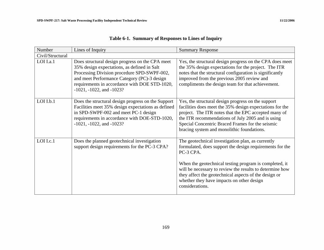
SPD-SWPF-217: Salt Waste Processing Facility Independent Technical Review 11/22/2006
Table 6-1. Summary of Responses to Lines of Inquiry Number Lines of Inquiry Summary Response Civil/Structural LOI I.a.1 Does structural design progress on the CPA meet
35% design expectations, as defined in Salt Processing Division procedure SPD-SWPF-002, and meet Performance Category (PC)-3 design requirements in accordance with DOE STD-1020, -1021, -1022, and -1023?
Yes, the structural design progress on the CPA does meet the 35% design expectations for the project. The ITR notes that the structural configuration is significantly improved from the previous 2005 review and compliments the design team for that achievement.
LOI I.b.1 Does the structural design progress on the Support Facilities meet 35% design expectations as defined in SPD-SWPF-002 and meet PC-1 design requirements in accordance with DOE-STD-1020, -1021, -1022, and -1023?
Yes, the structural design progress on the support facilities does meet the 35% design expectations for the project. The ITR notes that the EPC accepted many of the ITR recommendations of July 2005 and is using Special Concentric Braced Frames for the seismic bracing system and monolithic foundations.
LOI I.c.1 Does the planned geotechnical investigation support design requirements for the PC-3 CPA?
The geotechnical investigation plan, as currently formulated, does support the design requirements for the PC-3 CPA. When the geotechnical testing program is completed, it will be necessary to review the results to determine how they affect the geotechnical aspects of the design or whether they have impacts on other design considerations.
169

SPD-SWPF-217: Salt Waste Processing Facility Independent Technical Review 11/22/2006
Number Lines of Inquiry Summary Response LOI I.d.1 Have all structural risks been identified and
addressed; do any remain?
Not all structural risks have been identified. The ITR identified the following three risks that should be incorporated into the SWPF Risk Assessment and Management Plan for purposes of developing mitigation strategies, tracking and regular follow up.
LOI I.d.2 Have risks resulting from the conversion from ISO-9001 to NQA-1 been adequately addressed?
The ITR does not believe so. The change in project quality standard from ISO-9001 to NQA-1 could have a major impact in two areas with attendant risks of possible unplanned schedule and cost impacts. These arise from the rigorous and highly detailed requirement to verify and validate the computer codes used in the dynamic analysis and design efforts to ensure their NQA-1 compliance. Further, NQA-1 requirements will impact geotechnical work and analyses, and the requirements will flow down to the geotechnical subcontractors, including transportation of samples and laboratory testing/reporting activities.
Facility Safety LOI II.a.1 Do the tanks, piping, structure provide sufficient
confinement of radiological material consistent with PC-3 requirements?
The preliminary design of the facility does include seismic criteria consistent with Performance Category 3. These criteria are applied to tanks, piping, and structure to prevent failure resulting in release of radioactive material into the facility. (See materials evaluation for vessels, piping, and valves.)
170

SPD-SWPF-217: Salt Waste Processing Facility Independent Technical Review 11/22/2006
Number Lines of Inquiry Summary Response LOI II.a.2 Are the concrete walls of sufficient thickness to
meet 10 CFR 835 requirements?
Yes. It is concluded that the methods, approach, and results for bulk wall shielding design is very good. The design will be able to achieve 0.5 mR/hr or less for continuously occupied areas.
LOI II.a.3 Are the penetrations and galleries adequately designed to meet 10 CFR 835 requirements?
It is too early in the design to review results of analysis and resulting design configurations. However, it is concluded that the planned methods and the available capability are sufficient to address streaming and scattered radiation.
LOI II.a.4(i) Have all radiation protection risks been identified and addressed; do any remain?
Few preliminary design project risks are radiation protection related. Those that are significant relate to the maintenance-related worker exposure. As addressed above, it is concerning that the “de-inventory, flush, then hands-on maintenance” approach may result in unacceptable maintenance worker exposure. It is important that the SWPF project gain as much information from facilities with similar materials, to better understand this issue.
LOI II.a.4(ii) Have risks resulting from the conversion from ISO-9001 to NQA-1 been adequately addressed?
Conversion from ISO-9001 to NQA-1 is anticipated to have little effect on Radiation Protection at this point in the project.
171

SPD-SWPF-217: Salt Waste Processing Facility Independent Technical Review 11/22/2006
Number Lines of Inquiry Summary Response LOI II.b.1 Does the planned operating envelop safely support
radiation/contamination controls, maintenance and operation of all components?
From a safety aspect, it is apparent that a “hands-on” approach will be used for removal/replacement and maintaining the process equipment. It is critical that the decontamination process is adequate for the equipment components to be handled for removal. Without adequate and achievable controls and decontamination methods, in conjunction with subsequent process equipment module design features, the consistent achievement of ALARA goals will be problematic.
LOI II.b.2 Does the planned operating envelop safely support maintenance and operation of all components?
From a safety aspect, it is apparent that a “hands-on” approach will be used for removal/replacement and maintaining the process equipment. It is critical that the decontamination process is adequate for the equipment components to be handled for removal. Without adequate and achievable controls and decontamination methods, in conjunction with subsequent process equipment module design features, the consistent achievement of ALARA goals will be problematic.
LOI II.b.3 Are the handling systems adequate to safely support movement, analysis, and disposal of samples to support the production capacity of the SWPF?
The CD-2 design document deliverables for the Conveyors and Gloveboxes/Radiohoods have in place the base operational configuration within the Laboratory. The operating envelop of the conveyors is considered functional. The maintenance accessibility is considered acceptable, excluding Hot Cell Conveyor CV-05, pending final design of the conveyors. From a safety aspect, the equipment will require “hands-on” maintenance.
172
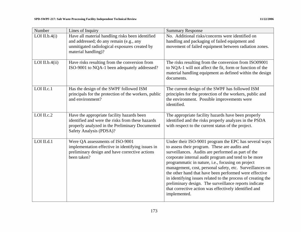
SPD-SWPF-217: Salt Waste Processing Facility Independent Technical Review 11/22/2006
Number Lines of Inquiry Summary Response LOI II.b.4(i) Have all material handling risks been identified
and addressed; do any remain (e.g., any unmitigated radiological exposures created by material handling)?
No. Additional risks/concerns were identified on handling and packaging of failed equipment and movement of failed equipment between radiation zones.
LOI II.b.4(ii) Have risks resulting from the conversion from ISO-9001 to NQA-1 been adequately addressed?
The risks resulting from the conversion from ISO09001 to NQA-1 will not affect the fit, form or function of the material handling equipment as defined within the design documents.
LOI II.c.1 Has the design of the SWPF followed ISM principals for the protection of the workers, public and environment?
The current design of the SWPF has followed ISM principles for the protection of the workers, public and the environment. Possible improvements were identified.
LOI II.c.2 Have the appropriate facility hazards been identified and were the risks from these hazards properly analyzed in the Preliminary Documented Safety Analysis (PDSA)?
The appropriate facility hazards have been properly identified and the risks properly analyzes in the PSDA with respect to the current status of the project.
LOI II.d.1 Were QA assessments of ISO-9001 implementation effective in identifying issues in preliminary design and have corrective actions been taken?
Under their ISO-9001 program the EPC has several ways to assess their program. These are audits and surveillances. Audits are performed as part of the corporate internal audit program and tend to be more programmatic in nature, i.e., focusing on project management, cost, personal safety, etc. Surveillances on the other hand that have been performed were effective in identifying issues related to the process of creating the preliminary design. The surveillance reports indicate that corrective action was effectively identified and implemented.
173

SPD-SWPF-217: Salt Waste Processing Facility Independent Technical Review 11/22/2006
Number Lines of Inquiry Summary Response LOI II.d.2 Have the impacts of conversion to NQA-1 after
preliminary design been assessed adequately?
No, the assessment to date is not adequate. The EPC conducted a gap analysis to determine what parts of their existing ISO-9001 program needed to be modified. The result of this gap analysis led to recommendations to change over 30 procedures. Absent from this gap analysis is an analysis of the impact of the changes on design work that has been performed.
LOI II.d.3 Do the impacts of NQA-1 challenge any of the completed design?
From a quality perspective the impacts of NQA-1 will probably not challenge the completed design. The impacts will tend to be deficiencies in documentation and records.
Engineering LOI III.a.1 Does the maturity of the process design support
35% completion status, as defined in Salt Processing Division procedure SPD-SWPF-002?
The assessments specifically determined the maturity of the process design supports 35% completion status.
LOI III.a.2 Do the Caustic Side Solvent Extraction (CSSX) test program plans and results provide sufficient assurance that engineering development for this technology has reached the necessary technical maturity required for final design?
Yes, but in addition the full scale testing offers an opportunity for mechanical testing and study. Vibration analyses should be made on the banks of contactors. For greater usefulness the Mechanical Design Group needs to be involved and perhaps outside expertise to make sure that the units are prototypic enough to give useful information.
LOI III.a.3 Do the Monosodium Titanate (MST)/Filtration test program plans and results provide sufficient assurance that engineering development for this technology has reached the necessary technical maturity required for final design?
Yes. It also presents an opportunity to lean more about APA operation as discussed herein.
174

SPD-SWPF-217: Salt Waste Processing Facility Independent Technical Review 11/22/2006
Number Lines of Inquiry Summary Response LOI III.b.1(i) Does the maturity of the
equipment/piping/tank/HVAC design support 35% completion status, as defined in Salt Processing Division procedure SPD-SWPF-002?
Overall, the maturity of the Mechanical Equipment, Piping and Tank design at this stage of the project supports the assertion of a 35% complete design.
LOI III.b.1(ii) Are the design designations for the PC-3 and PC-1 piping, vessels, and equipment adequate?
The criteria being applied by the EPC for the design of PC-1, -2, and –3 equipment, piping, vessels and Tanks is consistent with the SWPF design codes of record and DOE Orders and Standards.
LOI III.b.2 Does the maturity of the HVAC (Building ventilation, Process Vessel Vent System [PVVS], and Process Mixer Vent System [PMVS]) design support 35% completion status, as defined in Salt Processing Division procedure SPD-SWPF-002?
The maturity of the HVAC design supports 35% completion status (CD-2) as defined in SPD-SWPF-002.
LOI III.b.1(ii) Adequacy of PC-3 and PC-1 HVAC Design As detailed on the HVAC Air Flow and Control drawings, the design of all HVAC SSCs is performance category PC-1 except for portions of the PVVS which are seismic PC-3 in the dark cells. The PC-3 portions of the PVVS include the Air Dilution piping for tank inlet air flow and exhaust ventilation piping from the tank outlet through the first isolation valve outside of the process cell. The PC-3 classification of the PVVS piping in the dark cell ensures piping will maintain its’ integrity and a portable air mover could be set up outside the cells following a seismic event if required.
175

SPD-SWPF-217: Salt Waste Processing Facility Independent Technical Review 11/22/2006
Number Lines of Inquiry Summary Response LOI III.c.1 Although the electrical design generally trails the
other disciplines, is the electrical portion of the design sufficiently mature to define all major components (e.g., transformers) as well as sufficient electrical capacity to provide for future expansion?
The level of maturity of the electrical system is in excess of the 35% design point. In many cases the level of detail in design such as grounding, lighting, receptacles are well in advance of what is expected at this stage of the project. All of the major electrical equipment has been defined and physically located. However, as outlined below, further evaluation needs to take place of the electrical capacities of the system.
LOI III.c.2 Are basic cable tray layouts sufficiently developed to provide an accurate construction cost estimate?
The cable tray systems shown in the 35% package will support an accurate construction estimate when conservative contingency factors are applied to address an evolving design.
LOI III.d.1 Although the I&C design generally trails the other disciplines, is the I&C design sufficiently mature to define all major components (e.g., number of Input/Output) as well as sufficient surplus capacity to provide for future expansion?
The level of maturity of the Instrumentation and Control (I&C) systems is in excess of the 35% design point. All necessary major equipment has been identified and in most cases the specific vendor supplied equipment identified. The number of input/output points and the number of control loops have been specified to include all that are currently identified plus 25% spare capacity. In addition, the equipment and technology being employed on the project allows for easy expansion of the system.
176
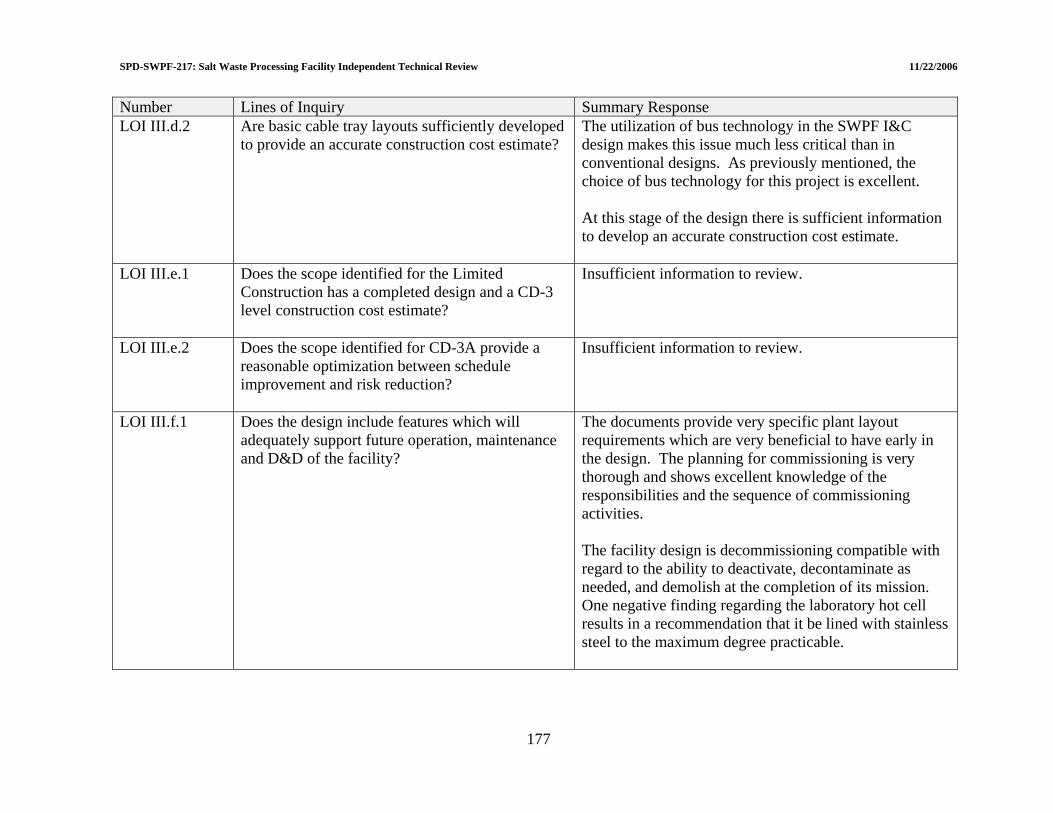
SPD-SWPF-217: Salt Waste Processing Facility Independent Technical Review 11/22/2006
Number Lines of Inquiry Summary Response LOI III.d.2 Are basic cable tray layouts sufficiently developed
to provide an accurate construction cost estimate?
The utilization of bus technology in the SWPF I&C design makes this issue much less critical than in conventional designs. As previously mentioned, the choice of bus technology for this project is excellent. At this stage of the design there is sufficient information to develop an accurate construction cost estimate.
LOI III.e.1 Does the scope identified for the Limited Construction has a completed design and a CD-3 level construction cost estimate?
Insufficient information to review.
LOI III.e.2 Does the scope identified for CD-3A provide a reasonable optimization between schedule improvement and risk reduction?
Insufficient information to review.
LOI III.f.1 Does the design include features which will adequately support future operation, maintenance and D&D of the facility?
The documents provide very specific plant layout requirements which are very beneficial to have early in the design. The planning for commissioning is very thorough and shows excellent knowledge of the responsibilities and the sequence of commissioning activities. The facility design is decommissioning compatible with regard to the ability to deactivate, decontaminate as needed, and demolish at the completion of its mission. One negative finding regarding the laboratory hot cell results in a recommendation that it be lined with stainless steel to the maximum degree practicable.
177

WPF-217: Salt Waste Processing Facility Independent Technical Review 11/22/2006
178
Number Lines of Inquiry Summary Response LOI III.g.1 Have all engineering risks been identified and
addressed; do any remain?
All engineering risks have not been identified and addressed. The EPC has been receptive to recommendations identifying risks and plans action to minimize or remove risks.
LOI III.g.2 Have risks resulting from the conversion from ISO-9001 to NQA-1 been adequately addressed?
No, the assessment to date is not adequate. The EPC conducted a gap analysis to determine what parts of their existing ISO-9001 program needed to be modified. The results of this gap analysis led to recommendations to change over 30 procedures. This gap analysis did not include an analysis of the impact of the changes on design work that has been performed.
SPD-S
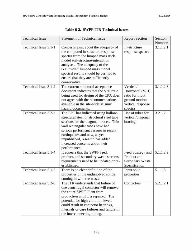
SPD-SWPF-217: Salt Waste Processing Facility Independent Technical Review 11/22/2006
Table 6-2. SWPF ITR Technical Issues Technical Issue Statement of Technical Issue Report Section Section
Number Technical Issue 3.1-1 Concerns exist about the adequacy of
the computed in-structure response spectra from the lumped mass stick model soil-structure-interaction analyses. The adequacy of the GTStrudL® lumped mass model spectral results should be verified to ensure that they are sufficiently conservative.
In-structure response spectra
3.1.1.2.1
Technical Issue 3.1-2 The current structural acceptance document indicates that the V/H ratio being used for design of the CPA does not agree with the recommendations available in the site-wide seismic hazard documents.
Vertical/ Horizontal (V/H) ratio for input ground motion vertical response spectra
3.1.1.2.3
Technical Issue 3.2-3 The EPC has indicated using hollow-structural steel or structural steel tube sections for the diagonal braces. Thin wall rectangular tubes have had serious performance issues in recent earthquakes and new, as yet unpublished, research has added increased concerns about their performance.
Use of tubes for vertical/diagonal bracing
3.2.1.2
Technical Issue 5.1-4 It appears that the SWPF feed, product, and secondary waste streams requirements need to be updated or re-established.
Feed Strategy and Product and Secondary Waste Specification
5.1.1.2.2
Technical Issue 5.1-5 There is no clear definition of the properties of the undissolved solids coming in with the waste.
Input solid properties
5.1.1.5
Technical Issue 5.2-6 The ITR understands that failure of one centrifugal contactor will remove the entire SWPF Plant from production until it is repaired. The potential for high vibration levels could result in contactor bearings, internals or case failures and failure in the interconnecting piping.
Contactors 5.2.1.2.1
179
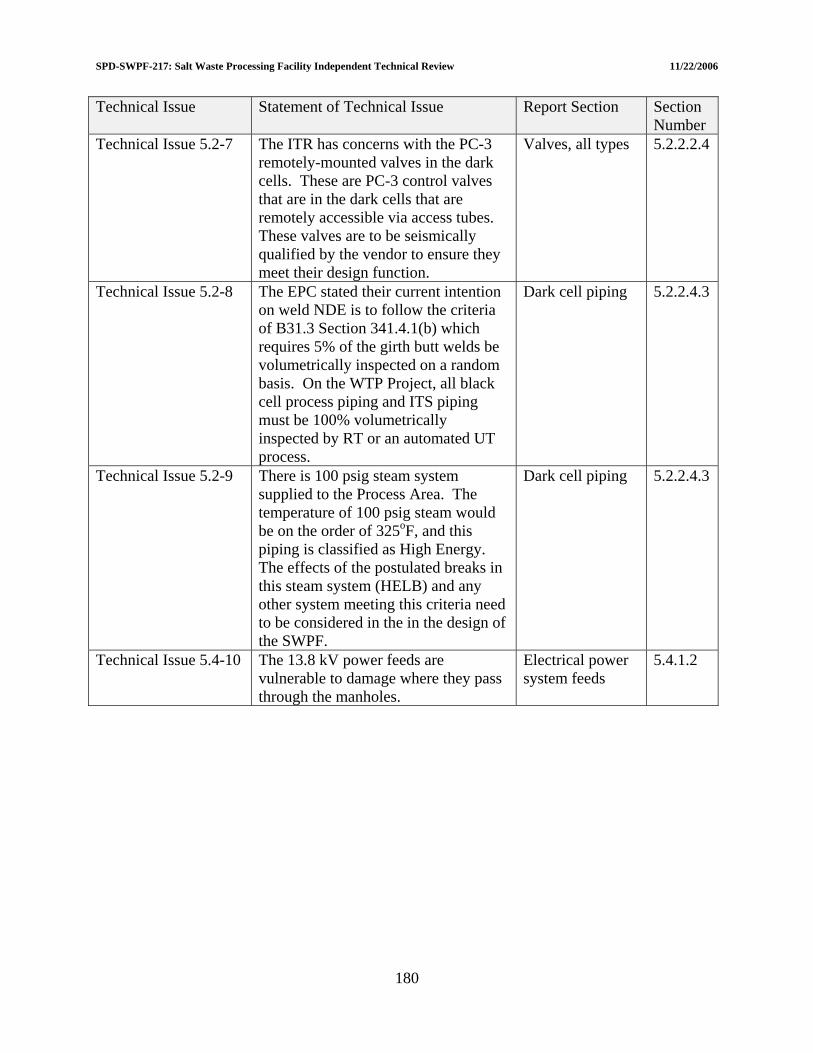
SPD-SWPF-217: Salt Waste Processing Facility Independent Technical Review 11/22/2006
Technical Issue Statement of Technical Issue Report Section Section Number
Technical Issue 5.2-7 The ITR has concerns with the PC-3 remotely-mounted valves in the dark cells. These are PC-3 control valves that are in the dark cells that are remotely accessible via access tubes. These valves are to be seismically qualified by the vendor to ensure they meet their design function.
Valves, all types 5.2.2.2.4
Technical Issue 5.2-8 The EPC stated their current intention on weld NDE is to follow the criteria of B31.3 Section 341.4.1(b) which requires 5% of the girth butt welds be volumetrically inspected on a random basis. On the WTP Project, all black cell process piping and ITS piping must be 100% volumetrically inspected by RT or an automated UT process.
Dark cell piping 5.2.2.4.3
Technical Issue 5.2-9 There is 100 psig steam system supplied to the Process Area. The temperature of 100 psig steam would be on the order of 325oF, and this piping is classified as High Energy. The effects of the postulated breaks in this steam system (HELB) and any other system meeting this criteria need to be considered in the in the design of the SWPF.
Dark cell piping 5.2.2.4.3
Technical Issue 5.4-10 The 13.8 kV power feeds are vulnerable to damage where they pass through the manholes.
Electrical power system feeds
5.4.1.2
180

SPD-SWPF-217: Salt Waste Processing Facility Independent Technical Review 11/22/2006
ATTACHMENT 1
INDEPENDENT REVIEW CHARTER
1-1
SPD-SWPF-217: Salt Waste Processing Facility Independent Technical Review 11/22/2006 ATTACHMENT 1: INDEPENDENT TECHNICAL REVIEW CHARTER
Salt Waste Processing Facility Project Charter
Independent Technical Review
Revision 1
1-2
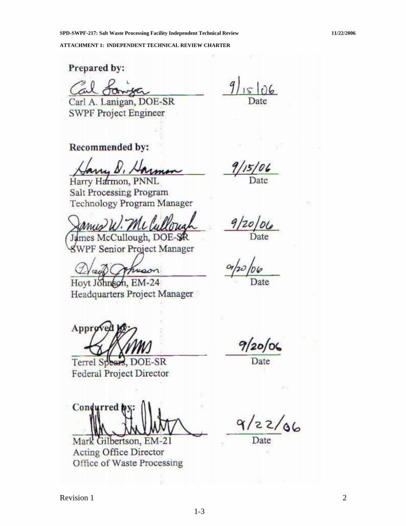
SPD-SWPF-217: Salt Waste Processing Facility Independent Technical Review 11/22/2006 ATTACHMENT 1: INDEPENDENT TECHNICAL REVIEW CHARTER
Revision 1 2
1-3
SPD-SWPF-217: Salt Waste Processing Facility Independent Technical Review 11/22/2006 ATTACHMENT 1: INDEPENDENT TECHNICAL REVIEW CHARTER 1. Goal This independent review is focused on evaluating the sufficiency of design to support development of a baseline cost and schedule (Critical Decision-2 [CD]-2) per DOE Order 413.3. As such, the design should be mature enough to support development of “detailed, resource loaded schedules and cost estimate for the entire project...” In addition, the Performance Baseline “shall account for risks and mitigation strategies...”. The results of the review will be used to see if the current design is mature enough to request CD-2. 2. Scope and Lines of Inquiry The scope of the Independent Technical Review (ITR) has been defined in the form of Lines of Inquiry (LOI) that will serve as the framework for review team activities and for selection of review team members. The LOIs will be grouped into three categories: (1) Civil/Structural Design, (2) Facility Safety, and (3) Engineering. The ITR Team shall focus their attention on the specific subjects identified by the LOIs. Any deviation from the LOIs must get prior approval of the Salt Waste Processing Facility (SWPF) Senior Project Manager and this Charter modified with the new scope before proceeding. The general review priority will be Central Processing Area (CPA), Alpha Finishing Facility (AFF), and remaining support facilities in that order. The following documents are general reference information for all technical reviews and are currently available:
• Standards/Requirements Identification Documents (S/RID) • Design Criteria Database • Basis of Design • Operations Requirements Document • General Arrangement Drawings • Risk Assessment and Management Plan
The LOIs are as follows:
I. Civil/Structural Design
a) Central Processing Area (CPA) • Does structural design progress on the CPA meet 35% design expectations, as
defined in Salt Processing Division procedure SPD-SWPF-002, and meet Performance Category (PC)-3 design requirements in accordance with DOE STD-1020, -1021, -1022, and -1023?
Revision 1 2
1-3

SPD-SWPF-217: Salt Waste Processing Facility Independent Technical Review 11/22/2006 ATTACHMENT 1: INDEPENDENT TECHNICAL REVIEW CHARTER
b) Support Facilities • Does structural design progress on the support facilities meet 35% design
expectations, as defined in Salt Processing Division procedure SPD-SWPF-002, and meet PC-1 design requirements in accordance with DOE STD-1020, -1021, -1022, and -1023?
c) Subsurface Design
• Does the planned Geotechnical investigation support design requirements for the PC-3 CPA?
d) Risk Management
• Have all structural risks been identified and addressed; do any remain? • Have risks resulting from the conversion from ISO-9001 to NQA-1 been
adequately addressed?
II. Facility Safety
a) Radiation Protection • Confinement
– Do the tanks, piping, structure provide sufficient confinement of radiological material consistent with PC-3 requirements?
• Bulk Wall Shielding – Are the concrete walls of sufficient thickness to meet 10 CFR 835
requirements? • Radiation scatter through penetrations (e.g. ventilation, piping, etc.) and pump
and valve gallery labyrinths – Are the penetrations and galleries adequately designed to meet 10 CFR 835
requirements? • Risk Management
– Have all radiation protection risks been identified and addressed; do any remain?
– Have risks resulting from the conversion from ISO-9001 to NQA-1 been adequately addressed?
b) Material Handling
• Overhead Cranes/Hoists – Does the planned operating envelop safely support radiation/contamination
controls, maintenance and operation of all components? • Equipment Monorails/Carts
– Does the planned operating envelop safely support maintenance and operation of all components?
• Laboratory conveyor/glove boxes – Are the handling systems adequate to safely support movement, analysis, and
disposal of samples to support the production capacity of the SWPF?
Revision 1 3
1-4

SPD-SWPF-217: Salt Waste Processing Facility Independent Technical Review 11/22/2006 ATTACHMENT 1: INDEPENDENT TECHNICAL REVIEW CHARTER
• Risk Management – Have all material handling risks been identified and addressed; do any
remain (e.g., any unmitigated radiological exposures created by material handling)?
– Have risks resulting from the conversion from ISO-9001 to NQA-1 been adequately addressed?
c) Integrated Safety Management (ISM)
• Integration of ISM in the design of the SWPF – Has the design of the SWPF followed ISM principals for the protection of the
workers, public and environment? "Have the appropriate facility hazards been identified and were the risks from these hazards properly analyzed in the Preliminary Documented Safety Analysis (PDSA)?"
d) Quality Assurance (QA) • Application of QA in the design of SWPF
– Were QA assessments of ISO-9001 implementation effective in identifying issues in preliminary design and have corrective actions been taken?
– Have the impacts of conversion to NQA-1 after preliminary design been assessed adequately?
– Do the impacts of NQA-1 challenge any of the completed design?
III. Engineering
a) Process Design • Does the maturity of the process design support 35% completion status, as
defined in Salt Processing Division procedure SPD-SWPF-002? • Do the Caustic Side Solvent Extraction (CSSX) test program plans and results
provide sufficient assurance that engineering development for this technology has reached the necessary technical maturity required for final design?
• Do the Monosodium Titanate (MST)/Filtration test program plans and results provide sufficient assurance that engineering development for this technology has reached the necessary technical maturity required for final design?
b) Mechanical Equipment/Piping/Tank Design/ Heating, Ventilation, and Air
Conditioning (HVAC) • Does the maturity of the equipment/piping/tank/HVAC design support 35%
completion status, as defined in Salt Processing Division procedure SPD-SWPF-002? Are the design designations for the PC-3 and PC-1 piping, vessels, and equipment adequate?
• Does the maturity of the HVAC (Building ventilation, Process Vessel Vent System [PVVS], and Process Mixer Vent System [PMVS]) design support 35% completion status, as defined in Salt Processing Division procedure SPD-SWPF-002? – HVAC Drawings
Revision 1 4
1-5
SPD-SWPF-217: Salt Waste Processing Facility Independent Technical Review 11/22/2006 ATTACHMENT 1: INDEPENDENT TECHNICAL REVIEW CHARTER
– Building Ventilation, PVVS, and PMVS Sizing Calculations – HVAC Equipment Specifications
c) Electrical Design
• Although the electrical design generally trails the other disciplines, is the electrical portion of the design sufficiently mature to define all major components (e.g. transformers) as well as sufficient electrical capacity to provide for future expansion?
• Are basic cable tray layouts sufficiently developed to provide an accurate construction cost estimate?
d) Instrumentation and Control (I&C)
• Although the I&C design generally trails the other disciplines, is the I&C design sufficiently mature to define all major components (e.g. number of Input/Output) as well as sufficient surplus capacity to provide for future expansion?
• Are basic cable tray layouts sufficiently developed to provide an accurate construction cost estimate?
e) Limited Construction
• Does the scope identified for the Limited Construction has a completed design and a CD-3 level construction cost estimate?
• Does the scope identified for CD-3A provide a reasonable optimization between schedule improvement and risk reduction?
f) Operations / Maintenance / Decontamination & Decommissioning (D&D)
• Does the design include features which will adequately support future operation, maintenance and D&D of the facility?
g) Risk Management
• Have all engineering risks been identified and addressed; do any remain? Have risks resulting from the conversion from ISO-9001 to NQA-1 been adequately addressed?
3. Period of Review The current schedule shows that the final 35% design package will be provided to Department of Energy (DOE) on September 15, 2006. However, much of the design has already been completed. Therefore, the ITR team can start their review on August 29, 2006 after the initial kick-off meeting. A report summarizing the findings in the review needs to be given to DOE no later than November 17, 2006. Findings, however, shall be provided to DOE on a timely basis, so that they can be addressed in real-time. This will support providing a completed assessment to the DOE-Headquarters External Independent Review group. The attached IRT schedule identifies all activities associated with the review. Also attached is a man-hour estimate for categories II and III. The scope of work for category I is being paid for through an Interoffice Work Order
Revision 1 5
1-6
SPD-SWPF-217: Salt Waste Processing Facility Independent Technical Review 11/22/2006 ATTACHMENT 1: INDEPENDENT TECHNICAL REVIEW CHARTER DOE-SR has with Pacific Northwest National Laboratory (PNNL). The ITR team will be provided access to Parsons’ document control web site, which will have all SWPF design information as it becomes available. All documentation request and/or communications with Parsons will be made through Carl Lanigan. 4. Team Structure and Make-up In composite, the ITR will be comprised of experts with extensive experience in design, engineering and management of chemical processing and radioactive waste management systems. Individual expertise and experience will be commensurate with the LOI. The ITR members must be free of any conflicts of interests with Parsons or Washington Savannah River Company (WSRC). The ITR will be divided into three teams for each of the three categories identified in Section 2. Each of these teams will have a single point of contact to answer any questions/issues. Please note, during Preliminary Design, PNNL (at the request of DOE) gathered a team of civil and structural experts to review the SWPF building design. We are proposing to have PNNL gather the same team for Enhanced Preliminary Design. 5. Responsibilities
• Environmental Management Headquarters (EM HQ) EM HQ will review and approve the SWPF ITR charter and team members. They will also assure necessary communications with other EM entities that have an interest in the progress and outcome of the review and will arrange for necessary briefings or meetings that may be required.
• DOE-SR
The Senior Project Manager will provide input to EM HQ on the SWPF ITR charter and team members. He will also manage the interface between the SWPF contractor and the ITR. This includes facilitating technical presentations, supplying technical information and providing general logistics support.
• ITR Team
The ITR Team is responsible for conducting a professional review, resolving internal technical differences of opinions, organizing the final report, resolving comments on technical drafts, communicating with the Senior Project Manager concerning issues/needs of the ITR team in a timely fashion and producing a high quality review report.
The ITR Lead will be responsible for:
Revision 1 6
1-7

SPD-SWPF-217: Salt Waste Processing Facility Independent Technical Review 11/22/2006 ATTACHMENT 1: INDEPENDENT TECHNICAL REVIEW CHARTER
– being the single point of contact for the ITR team; – assure the ITR teams meets the milestones identified in the attached schedule; – being responsible for the final assessment report; and – keeping the ITR team effort focused on the LOIs.
6. Final Report The final product of the ITR work will be an assessment of the SWPF design based upon the LOIs. At a minimum the report should address:
• The ITR Team’s response to the LOIs of the three evaluation categories. • ITR conclusion as to the readiness of the SWPF project to enter final design. • Identification of any issues or concerns. • Recommendations for improvement.
7. Appendix
• ITR Schedule • Man-hour Estimate
Revision 1 7
1-8

SPD-SWPF-217: Salt Waste Processing Facility Independent Technical Review 11/22/2006 ATTACHMENT 1: SWPF INDEPENDENT REVIEW TEAM CHARTER
Revision 1 8 1-9

SPD-SWPF-217: Salt Waste Processing Facility Independent Technical Review 11/22/2006 ATTACHMENT 1: SWPF INDEPENDENT REVIEW TEAM CHARTER
INDEPENDENT TECHNICAL REVIEW MAN-HOUR ESTIMATE
Estimates for activities during specific periods are as follows: Week of August 28 – One to two day kickoff meeting in Aiken, SC. (16 hours) September 4 to September 15 – Possible individual review of project deliverables in preparation for next meeting, limited and variable time commitment. Deliverables will not all be complete until mid-September. (16 hours) Week of September 18 – Three day meeting focusing on detailed review of project deliverables in your area. (24 hours) September 25 – October 6 – Individual review and draft findings, limited and variable time commitment. (24 hours) Week of October 11 – Three day meeting focusing on continued detailed review of project deliverables in your area and drafting sections of review report. (24 hours) October 16 – 20 – Individual contributions compiled into a draft report by team leader, team members review and comment on draft. I may elect to choose Sub Team leads to help in report preparation. (16 hours) October 23 – Draft report due to DOE. November 6 -16 – Incorporate DOE comments, primarily by team leader with support as needed from team members. (4 hours) November 17 – Issue final report to DOE. Contingency 20% (25 hours) Total Hours Estimate Per Person = 150 hours (rounded up from 149) Minimum Three Trips Per Person
Revision 1 9 1-10

SPD-SWPF-217: Salt Waste Processing Facility Independent Technical Review 11/22/2006
ATTACHMENT 2
SWPF INDEPENDENT REVIEW TEAM RESUMES
2-1
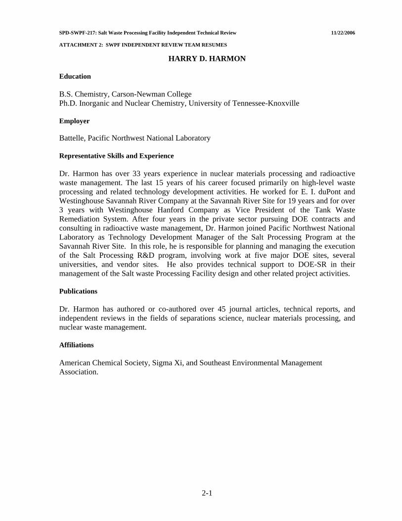
SPD-SWPF-217: Salt Waste Processing Facility Independent Technical Review 11/22/2006 ATTACHMENT 2: SWPF INDEPENDENT REVIEW TEAM RESUMES
HARRY D. HARMON Education B.S. Chemistry, Carson-Newman College Ph.D. Inorganic and Nuclear Chemistry, University of Tennessee-Knoxville Employer Battelle, Pacific Northwest National Laboratory Representative Skills and Experience Dr. Harmon has over 33 years experience in nuclear materials processing and radioactive waste management. The last 15 years of his career focused primarily on high-level waste processing and related technology development activities. He worked for E. I. duPont and Westinghouse Savannah River Company at the Savannah River Site for 19 years and for over 3 years with Westinghouse Hanford Company as Vice President of the Tank Waste Remediation System. After four years in the private sector pursuing DOE contracts and consulting in radioactive waste management, Dr. Harmon joined Pacific Northwest National Laboratory as Technology Development Manager of the Salt Processing Program at the Savannah River Site. In this role, he is responsible for planning and managing the execution of the Salt Processing R&D program, involving work at five major DOE sites, several universities, and vendor sites. He also provides technical support to DOE-SR in their management of the Salt waste Processing Facility design and other related project activities. Publications Dr. Harmon has authored or co-authored over 45 journal articles, technical reports, and independent reviews in the fields of separations science, nuclear materials processing, and nuclear waste management. Affiliations American Chemical Society, Sigma Xi, and Southeast Environmental Management Association.
2-1
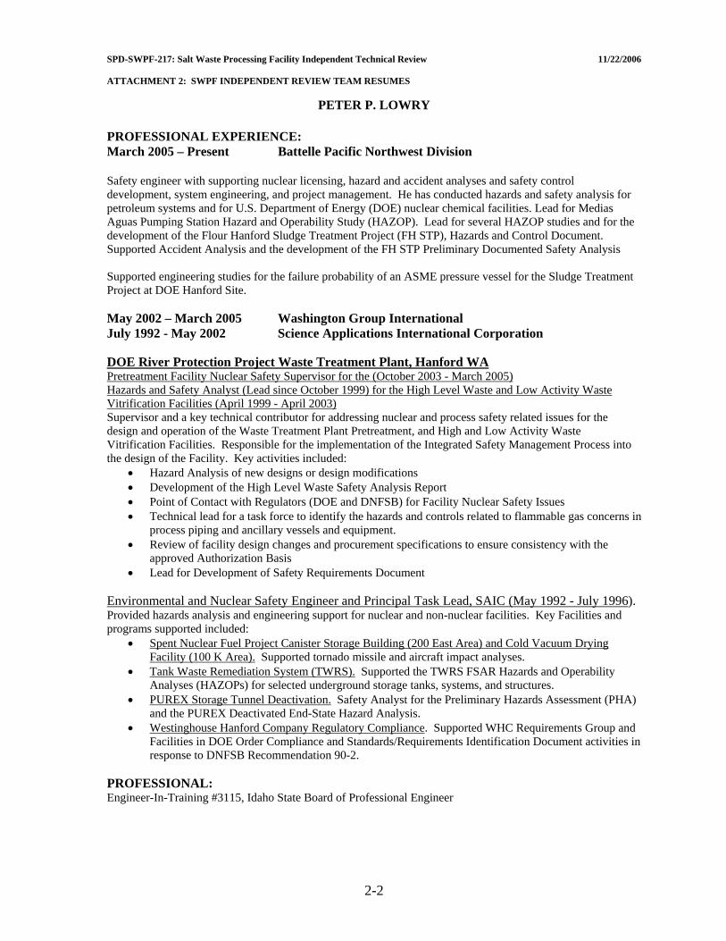
SPD-SWPF-217: Salt Waste Processing Facility Independent Technical Review 11/22/2006 ATTACHMENT 2: SWPF INDEPENDENT REVIEW TEAM RESUMES
PETER P. LOWRY PROFESSIONAL EXPERIENCE: March 2005 – Present Battelle Pacific Northwest Division Safety engineer with supporting nuclear licensing, hazard and accident analyses and safety control development, system engineering, and project management. He has conducted hazards and safety analysis for petroleum systems and for U.S. Department of Energy (DOE) nuclear chemical facilities. Lead for Medias Aguas Pumping Station Hazard and Operability Study (HAZOP). Lead for several HAZOP studies and for the development of the Flour Hanford Sludge Treatment Project (FH STP), Hazards and Control Document. Supported Accident Analysis and the development of the FH STP Preliminary Documented Safety Analysis Supported engineering studies for the failure probability of an ASME pressure vessel for the Sludge Treatment Project at DOE Hanford Site. May 2002 – March 2005 Washington Group International July 1992 - May 2002 Science Applications International Corporation DOE River Protection Project Waste Treatment Plant, Hanford WA Pretreatment Facility Nuclear Safety Supervisor for the (October 2003 - March 2005) Hazards and Safety Analyst (Lead since October 1999) for the High Level Waste and Low Activity Waste Vitrification Facilities (April 1999 - April 2003) Supervisor and a key technical contributor for addressing nuclear and process safety related issues for the design and operation of the Waste Treatment Plant Pretreatment, and High and Low Activity Waste Vitrification Facilities. Responsible for the implementation of the Integrated Safety Management Process into the design of the Facility. Key activities included:
• Hazard Analysis of new designs or design modifications • Development of the High Level Waste Safety Analysis Report • Point of Contact with Regulators (DOE and DNFSB) for Facility Nuclear Safety Issues • Technical lead for a task force to identify the hazards and controls related to flammable gas concerns in
process piping and ancillary vessels and equipment. • Review of facility design changes and procurement specifications to ensure consistency with the
approved Authorization Basis • Lead for Development of Safety Requirements Document
Environmental and Nuclear Safety Engineer and Principal Task Lead, SAIC (May 1992 - July 1996). Provided hazards analysis and engineering support for nuclear and non-nuclear facilities. Key Facilities and programs supported included:
• Spent Nuclear Fuel Project Canister Storage Building (200 East Area) and Cold Vacuum Drying Facility (100 K Area). Supported tornado missile and aircraft impact analyses.
• Tank Waste Remediation System (TWRS). Supported the TWRS FSAR Hazards and Operability Analyses (HAZOPs) for selected underground storage tanks, systems, and structures.
• PUREX Storage Tunnel Deactivation. Safety Analyst for the Preliminary Hazards Assessment (PHA) and the PUREX Deactivated End-State Hazard Analysis.
• Westinghouse Hanford Company Regulatory Compliance. Supported WHC Requirements Group and Facilities in DOE Order Compliance and Standards/Requirements Identification Document activities in response to DNFSB Recommendation 90-2.
PROFESSIONAL: Engineer-In-Training #3115, Idaho State Board of Professional Engineer
2-2

SPD-SWPF-217: Salt Waste Processing Facility Independent Technical Review 11/22/2006 ATTACHMENT 2: SWPF INDEPENDENT REVIEW TEAM RESUMES
CARL J. COSTANTINO Professor Emeritus
Department of Civil Engineering The City College of the
City University of New York EDUCATION
BCE 1956 City College of New York MSCE 1958 Columbia University PhD 1966 Illinois Institute of Technology
REGISTRATION - Registered Professional Engineer, New York State EXPERIENCE
1967 - 1996 Department of Civil Engineering, City University of New York Conducted research on stress wave propagation through soil and rock materials primarily associated with the seismic response of structures, with special emphasis on evaluation of critical facilities. Problems centered on the study of large strain and nonlinear effects on wave propagation, soil-structure interaction, and the influence of pore water on dynamic response. Directed the activities of Doctoral and Masters candidates. Co-Director of CUNY Center for Earthquake Engineering. 1975 - Present Seismic Consultant, Nuclear Regulatory Commission Perform seismic studies of nuclear reactor facilities for various divisions of NRC at both the design and review stages; assist NRR with evaluation of advanced reactor systems; perform research studies for Res. Div, develop computer programs (SIM, CARES, SLAVE, SLAM Codes) for NRC to assist in the review of facility designs; testify as expert witness at various licensing hearings conducted by NRC. 1985 - Present Seismic Consultant, Department of Energy Assist various divisions and field offices of the DOE in soils and seismic evaluations of critical facilities; serve as Peer Reviewer for various facility designs; perform safety evaluations for storage facilities (WIPP, Yucca Mountain); assist in the development of DOE safety assessment criteria; present results to Defense Nuclear Facilities Safety Board. 1971 - Present Soils Consultant, New York City Transit Authority Provide consulting services to NYCTA Engineers on soil and foundation projects at both the design and construction stages; assist in the development of Standards for Structural Design, Field Designs, and Soil Exploration; conduct laboratory testing of soil samples; design and inspect field monitoring programs. 1959 - 1967 IIT Research Institute, Chicago, Illinois Conduct research and serve as Principal Investigator on studies involving site hardening of missile systems, theoretical and experimental studies of soil-structure interaction; development of large FE programs for the Air Force to study wave propagation through nonlinear soil/rock systems; 1956 – 1958 Geotechnical Engineer, Tippetts, Abbott, McCarthy, Stratton Resident Engineer on earth moving project involving soil stabilization and compaction; field supervision of soils exploration programs for earth dam sites, flood control structures and river erosion projects.
2-3

SPD-SWPF-217: Salt Waste Processing Facility Independent Technical Review 11/22/2006 ATTACHMENT 2: SWPF INDEPENDENT REVIEW TEAM RESUMES
DR. ROBERT P. KENNEDY Structural Mechanics Consulting
28625 Mountain Meadow Road, Escondido, CA 92026 (760)751-3510 - (760) 751-3537 (Fax)
EDUCATION B.S. - Civil Engineering, Stanford University M.S. - Structural Engineering, Stanford University Ph.D. - Structural Engineering, Stanford University REGISTRATION Civil Engineer, State of California SUMMARY Forty years experience in static and dynamic analysis plus design of special purpose civil and mechanical-type structures, particularly for the nuclear, industrial, petroleum, and defense industries; design of structures to resist extreme loadings including seismic, missile impact, blast loads, extreme wind, impulsive loads, and nuclear environmental effects. PROFESSIONAL EXPERIENCE Seismic Ruggedness - Nuclear Facilities Developed performance-goal based seismic design criteria sections of ASCE/SEI Standard 43-05 “Seismic Design Criteria for Structures, Systems, and Components in Nuclear Facilities,” and DOE Standard 1020 “Natural Phenomena Hazards Design and Evaluation Criteria for Department of Energy Facilities.” Prior Chairman, Senior Seismic Review and Advisory Panel (SSRAP), jointly advising both nuclear power utilities and the U.S. NRC on issues relating to seismic ruggedness of existing nuclear power plants. Prior member of NRC Expert Panel on Seismic Margin for nuclear power plants. Co-author of Electric Power Research Institute (EPRI) Seismic Margin Methodology Report (EPRI-6041) and Methodology for Developing Seismic Fragilities (EPRI TR-103959). Provided technical direction on seismic fragility portion of seismic probabilistic risk assessments and seismic margin evaluations for more than 30 nuclear power plants. Developed the methodology most commonly used for such studies and author of many technical papers thereon. Taught numerous short courses on seismic PRA methodology in U.S., Spain, Taiwan, and People's Republic of China. Consultant on seismic evaluation or design for more than 50 nuclear facilities throughout world. Directed seismic analysis of many nuclear power plant buildings and components. Directed many nonlinear seismic response analyses investigations. Evaluated effects of differential earth movement (faulting) on nuclear facility. Performed a number of dynamic soil-structure interaction analyses of nuclear reactor containment building accounting for the nonlinear effects of base slab uplift. Directed nonlinear seismic evaluation of nuclear facility to demonstrate increased seismic capacity. Evaluated concepts for seismic response mitigation and increased energy absorption. Past Chairman, ASCE committee on seismic analysis of nuclear facilities. Past Chairman, ASCE committee which wrote ASCE Standard 4-86 "Seismic Analysis of Safety Related Nuclear Structures".
2-4

SPD-SWPF-217: Salt Waste Processing Facility Independent Technical Review 11/22/2006 ATTACHMENT 2: SWPF INDEPENDENT REVIEW TEAM RESUMES
LORING A. WYLLIE, JR. Structural Engineer and Senior Principal
Loring A. Wyllie, Jr. has over forty years of professional experience. His work has included seismic evaluations, analysis, and design of strengthening measures for improved seismic performance. A number of these buildings are of historical significance. He is a past Chairman of the State Historical Building Safety Board, whose mandate is to evaluate and analyze methods for strengthening buildings that preserve their historic character. Loring is a past-President of the Earthquake Engineering Research Institute (EERI). His contributions to the profession of structural engineering were recognized by his election to the National Academy of Engineering in 1990. He was made an Honorary Member of the Structural Engineers Association of Northern California and Earthquake Engineering Research Institute. In recognition of his expertise in concrete design and performance, the American Concrete Institute named him an Honorary Member in 2000. Loring was elected an Honorary Member of the American Society of Civil Engineers in 2001. EDUCATION B.S., with Highest Honors, University of California, Berkeley, 1960 M.S., University of California, Berkeley, 1962 REGISTRATION California – Structural Engineer, 1970 License No. 1648 California – Civil Engineer, 1967 License No. 17179 Registered Professional Engineer in Oregon, Utah, Nebraska, Texas, and Wyoming PROFESSIONAL AFFILIATIONS International Association for Bridge and Structural Engineering: Vice President, 1997 – 2001; Chairman, USA
Group, 1987 to present; Chairman, Organizing Committee, Annual Meeting, 1995; Member, Working Commission III, Reinforced Concrete, 1985 – 1993.
Earthquake Engineering Research Institute: President, 1995 -1997; Director, 1966 – 1989, 1994 – 1998; Member, Steering Committee, Eighth World Conference on Earthquake Engineering, 1984; Honorary Member 2005
State Historic Building Safety Board: State of California, 1976 to present; Chairman, 1993 – 1998; Vice-Chairman, 1990 – 1993.
American Society of Civil Engineers: President, San Francisco Section, 1980 – 1981; Chairman, Committee on Concrete and Masonry Structures, 1981 – 1984; Chairman, Joint ASCE-ACI Committee on Reinforced Concrete Columns; Member, Joint ASCE-ACI Committee on Joints and Connections in Monolithic Concrete Structures; Program Chairman, 1977 ACI Annual Convention; Member, Committee on Convention Policy; Honorary Member 2001.
American Concrete Institute: Director, 1985 – 1988; Member, Technical Activities Committee, 1982 – 1988; Member, Committee 318, Standard Building Code, 1972 to present; Honorary Member, 2000.
Structural Engineers Association of California: President, 1987 – 1988; Director, 1976 – 1980, 1986 -1989; Fellow Member, 2000.
Structural Engineers Association of Northern California: President, 1985 – 1986; Director, 1976 – 1978, 1984 – 1987; Chairman, Associates Activities Committee, 1967; Chairman, Building Codes Committee, 1971 – 1972; Chairman, Seismology Committee, 1975 – 1976, Honorary Member, 1998.
Building Seismic Safety Council: Chairman, Provisions Update Committee, 1988 – 1994; Member, 1994 to 2000.
U.S. National Academy of Engineering: Elected to membership, 1990; Chair of Civil Engineering Section, 1999 – 2001; Member, Civil Engineering Peer committee, 1997 – 2000.
International Association for Earthquake Engineering: Vice President 2000 – 2008.
2-5

SPD-SWPF-217: Salt Waste Processing Facility Independent Technical Review 11/22/2006 ATTACHMENT 2: SWPF INDEPENDENT REVIEW TEAM RESUMES
JOHN T. CHRISTIAN 23 Fredana Road
Waban, MA 02468–1103 Tel: (617) 244–0760, FAX: (617) 244–0816
e-mail: [email protected] Summary: John T. Christian has extensive experience in Geotechnical Engineering, Soil Dynamics, Earthquake Engineering, Geotechnical Reliability, Computer Applications, Finite Element Analysis, and Engineering Management. He is an expert on earthquake engineering, dynamic analysis, evaluation of soil liquefaction, amplification of seismic waves, stability of slopes, dynamic soil-structure interaction, and probabilistic seismic hazard assessments. His geotechnical engineering work has included earth dam analysis and design, evaluation of flow through porous media and earth dams, geotechnical aspects of nuclear power plants, solid waste landfills, foundation engineering, offshore caissons and production facilities, mooring facilities, and pipelines. He is a pioneer in the use of computer methods, the co-author and co-editor of a seminal book on Numerical Methods in Geotechnical Engineering, and co-author of a book on Productivity Tools for Geotechnical Engineers. His co-authored book on Reliability and Statistics in Geotechnical Engineering was published in 2003. As Vice President of a major engineering firm, he was involved in the design, evaluation, and construction of a large number of nuclear power plants and other facilities for energy generation and distribution. He also had a variety of corporate management functions, including oversight of computer activities, corporate computer disaster recovery, and standards and qualification of software. He has managed an expert system development group. He has applied probabilistic concepts to geotechnical engineering, winning the ASCE Middlebrooks Prize in 1996 for a paper on the uses of reliability approaches to the design of embankments. In 2002-2003 he served as the Chairman of the National Academy of Engineering committee that reviewed the status of the $14.6 billion Boston Central Artery/Tunnel Project (the “Big Dig”) and proposed management changes to expedite its completion. He is a member of the NAE Committee on New Orleans Regional Hurricane Projects. In addition to serving on the editorial boards of several professional journals, he has been the Editor-in-Chief of the ASCE Journal of Geotechnical and Geoenvironmental Engineering and is a charter member of the ASCE Geo-Institute's Committee on Computer Applications. He is the former Chairman of the Geotechnical Engineering Division of the American Society of Civil Engineers and of the U. S. National Society of the International Society of Soil Mechanics and Foundation Engineering. He is now a member of the board of the International Society of Soil Mechanics and Geotechnical Engineering. He is the former Chairman of the Engineering Accreditation Commission, Accreditation Board for Engineering and Technology, in which capacity he was instrumental in revising the undergraduate design criteria. He has been elected to membership in the National Academy of Engineering and to Honorary Membership in the American Society of Civil Engineers. He delivered the Terzaghi Lecture of the American Society of Civil Engineers in 2003. Publications: Over ninety refereed or invited papers and co-author or co-editor of three books. Professional Registrations: Massachusetts, Professional Engineer #23150 Maine, Professional Engineer #3608 Education: 1966 Massachusetts Institute of Technology, Cambridge, Massachusetts Ph. D. in Civil Engineering 1959 Massachusetts Institute of Technology, Cambridge, Massachusetts M. S. in Civil Engineering 1958 Massachusetts Institute of Technology, Cambridge, Massachusetts B. S. in Civil Engineering 1989 Northeastern University, Boston, Massachusetts Management Training Program
2-6

SPD-SWPF-217: Salt Waste Processing Facility Independent Technical Review 11/22/2006 ATTACHMENT 2: SWPF INDEPENDENT REVIEW TEAM RESUMES
DR. T. LESLIE YOUD Professor Emeritus
Department of Civil and Environmental Engineering, 368 Clyde Building Brigham Young University, Provo, Utah
801-422-6327 EDUCATION Ph.D, 1967, Iowa State University, Ames, Iowa (Geotechnical Engineering with dissertation on dynamic properties of sand) BS, April 1964, Brigham Young University, Provo, UT. EXPERIENCE 1967-1984, Research Civil Engineer, US Geological Survey, Menlo Park, CA. Conducted research in earthquake engineering with emphasis on liquefaction and ground failure. Conducted post-earthquake investigations, drilled and tested sites where liquefaction occurred, instrumented sites to monitor ground motions and pore pressures at liquefaction sites during future earthquakes. Developed procedures for mapping liquefaction hazard. 1984-2003 Professor, Brigham Young University, Provo, UT. Taught courses in geotechnical and earthquake engineering, continued research on liquefaction, consequent ground failure, and induced damage. Developed procedures for predicting lateral spread displacement. 2004-present, Professor Emeritus, continuing research and writing on liquefaction and ground failure and consulting on liquefaction hazard to pipelines, bridges and ports and industrial facilities. Patents Patent No. 4,840,230, wedging system for coupling accelerometers into boreholes Memberships/Institutional and Professional Service American Society of Civil Engineers; member of Executive Committee for Technical Council on Lifeline
Earthquake Engineering (TCLEE) Earthquake Engineering Research Institute; member learning from earthquakes committee International Society for Soil Mechanics and Geotechnical Engineering; member of committee TC-4,
geotechnical earthquake engineering Member, National Research Council Committee on Earthquake Engineering 1985-1991 Outside Reviewer, Canadian Liquefaction Experiment 1993-1997 Member, Utah Seismic Safety Commission 1994-1998, Chair 1994-1997 Member, National Research Council Committee on National Landslide Hazards Mitigation Strategy Chairman Utah Seismic Safety Commission 1994-1997 Member Utah Seismic Safety Commission Geoscience Committee Editorial Board, Engineering Geology, An International Journal (Elsevier) Honors and Awards BYU Carl G. Maeser Research and Creative Arts Award, 1991 Utah Engineering Educator of the Year, 1995 H Bolton Seed Medal, American Society of Civil Engineers, 2002 Elected Member, National Academy of Engineering, 2005 Elected Honorary Member, American Society of Civil Engineers, 2006 Publications and Presentations 75 papers in refereed journals or refereed U.S. Geological Survey publications 77 conference papers and other published reports 150 presentations at technical conferences and symposia
2-7
SPD-SWPF-217: Salt Waste Processing Facility Independent Technical Review 11/22/2006 ATTACHMENT 2: SWPF INDEPENDENT REVIEW TEAM RESUMES
THOMAS L. ANDERSON Dr. Anderson is an engineering consultant providing technical, management, policy and advisory assistance to a range of clients, including mission agencies and corporate groups. Recently he completed a 30-month assignment as Program Director, Division of Civil and Mechanical Systems, Directorate for Engineering, National Science Foundation, Arlington, Virginia. During this period he served as Project Manager for the $82 million George E. Brown, Jr. Network for Earthquake Engineering Simulation (NEES) Program, providing project management for all NEES experimental equipment awards. Previously Dr. Anderson spent 27 years with Fluor Daniel in a variety of assignments of increasing responsibility. Most recently he served as Executive Director of Engineering for Fluor Federal Services, and as Executive Director of Technology Management for Fluor Daniel Hanford. Tom is a structural engineer with expertise in earthquake engineering, science and technology policy, and industrial R&D. While on sabbatical leave from Fluor Daniel he completed a two-year postdoctoral fellowship at RAND’s Critical Technologies Institute in Washington, D.C., where he contributed to analytic support for science and technology policy formulation in the Executive Office of the President of the United States. Prior to that assignment, Dr. Anderson served as general manager of engineering services for Fluor Daniel’s southern California operations center where he was responsible for providing $250 million in engineering design services annually. His technical specialty is earthquake engineering and structural dynamics. His experience covers 45 years in various capacities, including design, management, contract R&D, policymaking, consulting, teaching and research. He holds BS(CE) and MS(CE) degrees from the University of Idaho and he earned his Ph.D. degree in civil engineering from the University of Colorado, from which he received its Distinguished Engineering Alumnus Award. Dr. Anderson is a member of numerous boards, committees and professional society organizations and has authored over 90 published papers and reports. He chaired the Implementation Advisory Committee for the Multidisciplinary Center for Earthquake Engineering Research and earlier completed a six-year term as a member of the National Research Council Board on Assessment of National Institute of Standards and Technology Programs. He served two years as liaison to the White House Office of Science and Technology Policy on the Construction and Building Subcommittee of the National Science and Technology Council, and he provided the secretariat for the National Earthquake Strategy Working Group. Tom and his wife, Sunny Ann, reside in Arlington, Virginia, and have five children.
2-8

SPD-SWPF-217: Salt Waste Processing Facility Independent Technical Review 11/22/2006 ATTACHMENT 2: SWPF INDEPENDENT REVIEW TEAM RESUMES
JAMES M. LANGSTED, CHP Scientist 5, Shaw Environmental & Infrastructure, Centennial (Denver), Colorado
PROFESSIONAL QUALIFICATIONS Mr. Langsted has 29 years experience in DOE safety programs including operations, implementation, and consulting. Expertise includes DOE Integrated Safety Management Systems, Authorization Basis, and Radiological Protection. He has implemented integrated safety controls at Department of Energy (DOE) and commercial facilities in both operations and D&D modes. He is certified by the American Board of Health Physics. He has strong technical ability to develop solutions that efficiently meet regulatory requirements and good safety practice. EDUCATION MS, Radiological Sciences, University of Washington, Seattle; 1977 BS, Psychology, University of Washington, Seattle; 1975 EXPERIENCE AND BACKGROUND Mixed Oxide Fuel Fabrication Facility – Responsible Engineer for procurement specifications; Duke, Cogema, Stone & Webster Implemented integrated radiological safety management at major DOE contractor during the initiation of decontamination and decommissioning of plutonium and uranium processing facility; Rocky Flats Plant Provided integrated safety input and oversight during the design and initial construction of a uranium processing low-level waste storage facility; Silo 3 – Fernald Environmental Management Site Participated in Readiness Reviews to assure compliance with regulatory and approved authorization basis requirements prior to startup; Hanford Site Authorization Basis Development - Developed initial and final Hazard Categorization for new facility and operations to retrieve, process, and package uranium processing waste from Silo-3 at the Fernald Environmental Management Project. Performed quantitative risk assessments on existing operations and proposed changes to assure operations fall within approved DOE Authorization Basis; Rocky Flats Plant Authorization Basis Maintenance - Performed Independent Verification of the adequacy and implementation of: approved Final Safety Analysis Report, Vital Safety System operability, and Technical Safety Requirement implementation; Rocky Flats Plant
2-9

SPD-SWPF-217: Salt Waste Processing Facility Independent Technical Review 11/22/2006 ATTACHMENT 2: SWPF INDEPENDENT REVIEW TEAM RESUMES
C. A. NEGIN, P. E. EDUCATION B.Sc. Mechanical Engineering, Massachusetts Institute of Technology, 1960 M.Sc. Mechanical Engineering Massachusetts Institute of Technology, 1961 Oak Ridge Practice School, Massachusetts Institute of Technology, 1961 PROFESSIONAL QUALIFICATIONS C.A. (Chuck) Negin’s career spans 45 years as a project manager, engineer, manager, consultant, and company officer. After obtaining an MSME from MIT, early experience included operations aboard a U.S. Navy surface ship, sea trial testing of submarines, shift supervision at nuclear submarine prototype, and startup testing at power plants. In the subsequent years, there have been assignments in every phase of commercial nuclear power including project management, analysis, design, construction, testing, operations, licensing, and development. Projects with government facilities, coal plants, and a natural gas pipeline have added to the mix. Clients have included electric utilities, the Electric Power Research Institute, the Department of Energy, and the International Atomic Energy Agency. Mr. Negin has worked cooperatively on projects with many of the major nuclear plant Architect Engineers, as the NSSS suppliers, and several DOE site contractors. Since the mid-1990’s, Mr. Negin has been directly involved with planning and execution of shutdown, deactivation, cleanup, and demolition of many of the DOE’s excess facilities. This work has been for both headquarters’ clientele and field project managers. In addition to progressing with utilities from their beginnings with nuclear power, and recently with the government in terminating operations of excess facilities, Mr. Negin has participated in a varied set of unique projects that have served to define industry direction and standards. These include initiating the concept of extending the service life of nuclear plants to 60 years, a pilot project at PUREX for establishing minimum surveillance and maintenance prior to decommissioning, the development of EPRI’s Advanced Light Water Reactor requirements, the cleanup of TMI-2, and the primary developer of MicroShield, which is radiation analysis software used worldwide by hundreds of engineers, waste managers, and health physicists. EXPERIENCE 1998 – Present Executive Consultant, Senior Vice President, Project Enhancement
Corporation 1995 – 1998 President, Oak Technologies (Sole Proprietor) 1982 – 1994 CEO, President, Consultant, Grove Engineering; Rockville 1978 – 1982 Manager & Consultant, International Energy Associates, Ltd. 1967 – 1978 Engineer/Consultant, NUS Corporation, Rockville, Maryland 1964 – 1966 Shift Supervisor at S1C Prototype, Combustion Engineering 1961 – 1964 U.S. Navy Engineering Duty Office, DD468, Assistant Ship
Superintendent, Naval Shipyard
2-10
SPD-SWPF-217: Salt Waste Processing Facility Independent Technical Review 11/22/2006 ATTACHMENT 2: SWPF INDEPENDENT REVIEW TEAM RESUMES
JERRY EVATT 319 Greenwich Dr. Aiken, S.C. 29803
Phone: (803) 642-9496 This abbreviated resume is in reference to my past seventeen (17) years experience at the Savannah River Site (SRS) with Bechtel National Inc. and Bechtel Savannah River Inc. as a Senior Mechanical Design Engineer, prior to my January 1, 2006 retirement. This resume is not intended to review my past experience in material handling and machine design with the Bechtel Corporation, Combustion Engineering Inc. and Kidde Consultants Inc. prior to my transfer to SRS. My specially and area of expertise over these seventeen (17) years was in the design/modification/fabrication of equipment and vessels for remote handling (In-Cell) equipment and fixtures used for placement and removal. Work History 1988 to 2006 Bechtel National, Inc./Bechtel Savannah River Co. Bechtel Resident Design Office/Design Engineering Defense Waste Processing Facility (DWPF) Position: Senior Mechanical Design Engineer
Responsible for the design, fabrication and modification of various plant and replacement equipment by remote methods. The design/fabrication of special equipment and fixtures for removal and replacement of same. The development of Equipment Requirement Drawings and technical specifications to support engineering deliverables, construction activities and client acceptance. Central Engineering (B-Area) Tritium Extraction Project
Responsible for the conceptual design and technical specifications for the “In Cell” Remote Handling Bridge
Crane, TPR Cask Handling Bridge Crane and Cask Handling Trolley. Design support for various project equipment to support remote handing. Defense Waste Processing Facility (DWPF) Low Currie Salt Projects Responsible for equipment modifications/new equipment and technical specifications to support the Low Currie Salt (LCS) 0.01 C/Gal. and 0.02 C/Gal. Projects at Saltstone (Z-Area). Education Oklahoma State University - Engineering Technology (Grad. 1960) Oklahoma Military Academy (Jr. College) - Mechanical Engineering (Grad. 1957) Other Member - Project Task Team Conceptual Design - Canister Shipping Facility (CSF) DWPF Member - Engineering Task Team Conceptual Design - Hanford Tank Waste Remediation Project
2-11

SPD-SWPF-217: Salt Waste Processing Facility Independent Technical Review 11/22/2006 ATTACHMENT 2: SWPF INDEPENDENT REVIEW TEAM RESUMES
RICHARD M. STARK ORGANIZATION Department of Energy, Office of Environmental Management EDUCATION Master of Science in Nuclear Engineering, Carnegie-Mellon University Bachelor of Science in Electrical Engineering, Carnegie-Mellon University Registered Professional Engineer (by exam) Commonwealth of Pennsylvania Commonwealth of Virginia “Q” Security Clearance RELEVANT EXPERIENCE 2003 - 2006 Director, Office of Facility Operations Support (EH-24) 1992 - 2003 Deputy Director, Office of Nuclear Safety Policy and Standards (EH-31) 1988 - 1992 Senior Executive Consultant, Nuclear Utilities Service Corporation
(NUS Corp.) 1985 - 1988 Senior Project Manager, Science Applications International Corporation
(SAIC) 1980 - 1985 Technical Assistant to the Director of Licensing, U.S. Nuclear Regulatory
Commission 1977 - 1980 Engineering Manager, Stone and Webster Engineering Corporation 1963 - 1977 Various Engineering Management functions, Westinghouse Electric
Corporation
2-12
SPD-SWPF-217: Salt Waste Processing Facility Independent Technical Review 11/22/2006 ATTACHMENT 2: SWPF INDEPENDENT REVIEW TEAM RESUMES
TODD LAPOINTE Mr. Todd Lapointe is a member of the Department of Energy's (DOE) Energy, Science and Environment (ESE) Chief of Nuclear Safety (CNS) Staff in Washington, D.C. Todd's duties include serving as the technical expert for conduct of operations, operational readiness assessments (ORRs), and integrated safety management (ISM) supporting line oversight, technical aspects of operational nuclear safety, related regulations & standards, and field assessments related to operational nuclear safety implementation. Mr. Lapointe has over 18 years of engineering, operations and technology management experience within and outside the DOE complex. He has supported the department's headquarters offices of Environmental Management (EM) and Environment, Safety & Health (EH) in the areas of conduct of operations assessment and safety performance metrics. Outside of the department he has managed operations, maintenance and business process analyses and reengineering activities for some of private industry's most respected manufacturing leaders including SC Johnson, Wyeth Pharmaceuticals and Akzo-Nobel, among others. Prior to working with DOE Mr. Lapointe gained recognized nuclear operational management, reactor operations and leadership experience as an Officer in a dynamic US submarine environment. Mr. Lapointe is a graduate of Maine Maritime Academy with a degree in Marine Engineering Operations and minors in Nuclear Engineering and Management as well as a graduate of the U.S. Navy's Nuclear Propulsion Officers Program and a decorated submarine veteran. He is also a recipient of the US Vice-Presidential National Performance Review "Hammer" Award for developing and coauthoring DOE's Performance Indicators for the Environment, Safety & Health Program. He resides his wife Megan in Baltimore, MD and works out of the Under Secretary's Office in the Headquarters Forrestal Building.
2-13
SPD-SWPF-217: Salt Waste Processing Facility Independent Technical Review 11/22/2006 ATTACHMENT 2: SWPF INDEPENDENT REVIEW TEAM RESUMES
NORMAN MOREAU Mr. Moreau the President and is a Senior Management Consultant for Theseus Professional Services, LLC. He has over 30 years of experience in quality and process management, project management, engineering, and organizational administration. Mr. Moreau has been a member of the American Society of Mechanical Engineers (ASME) since 1982 and since 1990 has been an active participant on the ASME Committee on Nuclear Quality Assurance. His significant contributions have been in the areas QA for computer software and records management. He has been on Main Committee since 2002 and since 2004 he has served as the Vice Chair, Subcommittee on Engineering and Procurement Processes. His DOE experience included providing project management and technical support to the Director of Facilities, Office of Nuclear Energy, Science and Technology (NE-40), Depleted Uranium Hexafluoride Program and serving as a quality management advisor supporting the Vitrification Projects and Spent Nuclear Fuels Program in the Office of Technical Services (EM-37). More recently he has worked as a software QA (SQA) technical specialist for the DOE YMP Office He has also participated as the SQA SME on WIPP Recertification Readiness. He has also supported two laboratories with quality assurance support in preparing the Mining and Chemical Combine Technologies, LLC (MCCT) to be a qualified DOE engineering services provider. Mr. Moreau’s commercial nuclear experience includes working at Ft. St. Vrain in Colorado, supporting organizations with their Unreviewed Safety Question programs, conducting commercial technical staff training and performing 10 CFR 50 Appendix B type audits for commercial vendors. Mr. Moreau received his B.S. in Mechanical Engineer from Colorado State University and received his M.S.A. in Software Engineering Administration from Central Michigan University.
2-14

SPD-SWPF-217: Salt Waste Processing Facility Independent Technical Review 11/22/2006 ATTACHMENT 2: SWPF INDEPENDENT REVIEW TEAM RESUMES GEORGE KRAUTER, P.E. Phone: 865-966-4508 11001 Farragut Hills Blvd. Fax: 865-966-4508 Knoxville, TN 37934 Email: [email protected] EXPERIENCE 1996-Present Independent Consultant
• Participated in the 2002 DOE OECM Project and Asset Management Conference, which was used to review and comment on the DOE Project Management directives and documents.
• Acted as the facilitator for the development of risk management plans for two Y-12 modernization projects.
• Directed the development of the Project Execution Plan update and the subordinate plans for the design and construction of two modernization projects at the Y-12 Plant.
• Participated in the preparation and presentation of a short course on review of project cost estimates for the DOE Savannah River Site Environmental Management Project Managers.
• Participated in the review of the decommissioning cost estimate for the Seabrook Nuclear Plant with particular emphasis on the contingency and escalation factors. Particular attention was directed to waste disposal and spent fuel costs in the future.
1979-1996 Various Companies Mr. Krauter was the Program Manager on four major DOD and DOE environmental restoration contracts each exceeding a value of $200 million. He has managed the decontamination and decommissioning of numerous radioactively contaminated facilities. In addition to his environmental project experience, he has a background in design and construction. Mr. Krauter managed two tasks at the DOE Savannah River Site. First, he led a team which prepared planning documents for the decommissioning of the R-reactor. He also directed an environmental inspection of P-reactor for placement in a stand-by condition. The inspection was to ensure compliance with RCRA, CERCLA, NEPA, Clean Air Act, Clean Water Act, and environmental radiation requirements. Mr. Krauter was the Program Manager for the Tank Farm Upgrades Program. This work included a $49 million cross-site transfer system construction, a $26 million vent system upgrade, a cathodic protection system of $7 million and the conceptual design of four new 1 million gallon waste tanks with a construction cost of $105 million. 1958-1979 U.S. Navy, Civil Engineer Corps - Ensign to Commander As the Officer in Charge of the Naval Nuclear Power Unit Commander Krauter’s primary responsibility was the decommissioning of the PM-3A, the Navy’s nuclear power reactor in the Antarctic. (1972 to 1974) EDUCATION 1965 – 1967 Naval Postgraduate School, Monterey, CA MS, Physics 1960 – 1961 Rensselaer Polytechnic Institute, Troy, NY BCE 1954–1958 U.S. Naval Academy, Annapolis, MD BS REGISTRATION Registered Professional Engineer, PA since 1968
2-15

SPD-SWPF-217: Salt Waste Processing Facility Independent Technical Review 11/22/2006 ATTACHMENT 2: SWPF INDEPENDENT REVIEW TEAM RESUMES ARTHUR WILLIAM ETCHELLS III Arthur W. Etchells is a world recognized authority in the field of mixing for the process industries. For thirty nine years he worked for the DuPont Company and for thirty years as an internal consultant for the many diverse DuPont businesses in the field of fluid flow with emphasis on mixing and slurry transport. He has achieved the highest technical level of DuPont Fellow and the highest technical award, the Lavoisier Medal. His outside activities such as teaching in universities and continuing education courses, publications, and lectures and his leadership in the world technical community have made him widely known and highly respected. He has contributed two chapters to the recent Handbook of Industrial Mixing (Wiley 2003). He is a past president of the North American Mixing Forum and winner of their award for contribution to mixing technology. By his efforts the technology of mixing has become better recognized and understood in the process industries and in the universities. He retired from DuPont in November 2002 but still works as a contract consultant. He is currently working for DuPont Safety Resources Business helping the Bechtel Company develop a facility for immobilizing radioactive waste at the Hanford site in the state of Washington and for DuPont Food Industry Solution business on several consulting programs along with other consulting.
2-16

SPD-SWPF-217: Salt Waste Processing Facility Independent Technical Review 11/22/2006 ATTACHMENT 2: SWPF INDEPENDENT REVIEW TEAM RESUMES
DR. OLIVER (OLLIE) BLOCK 238 W. Harvest Run Drive Idaho Falls, Idaho 83404
Phone: (208) 524-4674; Cell (208) 521-6326 Dr. Block has experience on DOE projects including: Calcine Disposition Engineering Manager at Idaho National Lab, Vitrification Process Technology Manager at Hanford, and Special Process Manager for the New Production Reactor (designed to produce tritium). He served as System Engineering Manager for the Initial Pretreatment Module, which furnished advanced process designs to separate and process waste fractions at DOE’s Hanford Waste Site. He received a commendation letter from DOE for outstanding support in carrying out DOE’s mission of Pollution Prevention/Waste Minimization. Dr. Block’s responsibilities for these DOE projects included development of project design criteria documents, development of interface control documents, system functional analysis, and project configuration management. Dr. Block technically supervised nuclear and chemical engineering on all of Ebasco and Raytheon [WGI predecessor companies] nuclear projects. He has extensive nuclear power plant experience in Water Treatment, Radwaste, and Shielding. His experience includes process flowsheet development, decommissioning planning and accident analysis, and radwaste processing systems. He has prepared Safety Analysis Reports, Environmental Reports required by regulatory agencies, and evaluated research and pilot plant design data for incorporation of equipment into water treatment and waste process systems. He has provided new plant designs and retrofits for a range of nuclear power plants and process plants. Responsibilities have included supervision of design efforts such as: preparation of conceptual design descriptions, flow diagram, P&ID development, writing equipment specifications, equipment procurement, and review of vendor drawings. He has led plant retrofits, which included the incorporation of advanced filtration systems, calciners, thin film evaporators, ion exchange processes, high force compactors, incinerators, reverse osmosis, and extruder/evaporators, and solidification systems. He has extensive knowledge of power plant chemistry and has implemented system design to satisfy evolving chemical criteria; improvement of processes and equipment design including materials and reducing radiation exposures (ALARA philosophy); Dr. Block’s system responsibilities include: nuclear reactor water clean-up, chemical and volume control, boron management, combustible gas control (post LOCA), steam generator blowdown, fuel pool cleanup, decontamination, containment spray, safety injection, and waste processing. PROFESSIONAL EXPERIENCE
IDAHO CLEANUP PROJECT (CH2M♦WG) 2005 to Present CWI Engineering Manager for the Calcine Disposition Project for the Idaho Cleanup Project. Responsible for engineering and design for retrieval of calcine and processing to make calcine ready for off-site shipment. Providing engineering/design input for DOE interfaces, regulatory interfaces, and site interfaces.
CHIEF NUCLEAR ENGINEER – NUCLEAR PROCESS DEPARTMENT (Washington Group International/Raytheon E&C) Princeton, New Jersey 1988-2001 Discipline Manager with responsibilities for administrative and technical products of the department. Technically supervised radwaste and water treatment engineering on all Raytheon nuclear projects
EDUCATION
PhD, Kansas State University M.S., Kansas State University, 1969; Major: Nuclear Engineering B.S., University of Nebraska, 1965; Major: Chemical Engineering
Licenses/Registrations/Certifications
Professional Engineer License – Idaho, Washington Inactive PE’s - New York, Tennessee
2-17

SPD-SWPF-217: Salt Waste Processing Facility Independent Technical Review 11/22/2006 ATTACHMENT 2: SWPF INDEPENDENT REVIEW TEAM RESUMES
TIMOTHY M. ADAMS Stevenson and Associates, Cleveland, Ohio
EDUCATION MS Mechanical Engineering, University of Pittsburgh, 1985 BS Mechanical Engineering, Summa Cum Laude, University of Pittsburgh, 1977 REGISTRATION/CERTIFICATION Certified Pennsylvania Engineer in Training (EIT) PROFESSIONAL HISTORY Stevenson & Associates, Cleveland, OH, Chief Mechanical Engineer and General Manager, Cleveland Office, 1991 - present Peak Technical Services Inc., Pittsburgh, PA, Director - ENSYS Division, 1989 - 1991 Westinghouse Electric Corporation, Pittsburgh, PA, 1977 - 1989 EXPERIENCE Mr. Adams is the Corporate Chief Mechanical Engineer and the General Manager of the Stevenson and Associates Cleveland Office. He has over 29 years experience in the design of Pressure Retaining Components to Section III and Section VIII of the ASME Boiler and Pressure Vessel Code and the B31 series Codes. In addition, to his general management responsibilities, Mr. Adams is responsible for: project management; and provision of technical consulting and design work in the areas of design/analysis of piping systems; pressure vessels/tanks; mechanical equipment; structures; and application of Industry Consensus Codes and Standards for the electric power generation; petrochemical; and, process industries and DOE nuclear waste processing facilities. Mr. Adams is an expert in the application of experience based and traditional qualification techniques to the seismic evaluation of piping systems (above ground, buried, etc.) valves, component equipment and supports. PUBLICATIONS Authored and co-authored over 40 technical publications in the Mechanical Engineering field. PROFESSIONAL ACTIVITIES Member, American Society of Mechanical Engineers (ASME); Member, American Welding Society (AWS); Member, American Society for Non-Destructive Testing (ASNT); Member, ASME BPVC III, Div. 1, Subgroup on Design; Member, ASME BPVC III, Div. 1, Working Group on Piping Design; Member, ASME BPVC III, Div.1, Working Group on Design Methods; Member, ASME BPVC III, Div.1, Working Group on Probabilistic Methods; Member, ASME BPVC III, Div.3, Working Group on Containment Design; Member, ASME BPVC Project Team on Seismic Issues and Project Team on Plastic Pipe; Member, ASME Main Committee on the Qualification of Mechanical Equipment in Nuclear Power Plants (ASME-QME); Member, ASME QME Subcommittee on General Requirements (QME-SCGR); Chairman, ASME QME Subgroup on Dynamic Qualification (QME-SDQ); Member Joint ASME/ASCE Special Task Group Buried Piping Design; ASME Alternate Representative to Building Seismic Safety Council (BSSC) EXPERTISE SUMMARY
• Piping and Pipe Support Design and Analysis • Vessel, Tank, Heat Exchanger, Valve Design and
Analysis • Containment Vessel Design and Analysis • Seismic Equipment Qualification • ASME BPVC, Section III, Section V, Section VIII • ASME B31 Series Codes, Including B31.1 and B31.3
• ASME QME-1 & IEEE 344 • Design of Nuclear Waste Management Facilities • Project Management • Experienced in 50.59 Screenings • Design for Natural Phenomenon Hazards • Operational Vibration Problem Resolution
2-18

SPD-SWPF-217: Salt Waste Processing Facility Independent Technical Review 11/22/2006 ATTACHMENT 2: SWPF INDEPENDENT REVIEW TEAM RESUMES
STEPHEN R. GOSSELIN EDUCATION MS Mechanical Engineering, University of North Carolina, Charlotte, NC, 1998 BS Mechanical Engineering, California State Polytechnic University, Pomona, CA, 1980 AREAS OF EXPERTISE Mr. Gosselin is a Chief Engineer in Pacific Northwest National Laboratory (PNNL) Computational Mechanics Group with over 30 years nuclear power industry experience. Mr. Gosselin’s areas of expertise include solid mechanics, fracture mechanics, probabilistic fracture mechanics, and risk-informed inspection for pressure vessels and piping in nuclear power plants. Since joining PNNL in 1998, and before that at the Electric Power Research Institute (EPRI) in 1993, his work has focused primarily on fitness-for-service, structural integrity, safety, and reliability of pressure vessels and piping components. He has made significant contributions in the areas of piping component fatigue analysis, flaw tolerance methodologies for nuclear component fitness for service, fatigue crack flaw detection probability, environmental fatigue computational methods, on-line fatigue monitoring in nuclear power plant piping components, and risk-informed inservice inspection. Mr. Gosselin’s computational expertise is complemented by over 13 years experience in mechanical systems design, analysis, operation and maintenance at Westinghouse and Combustion Engineering PWR commercial nuclear power plants at San Onofre Nuclear Generating Station and 8 years operating experience and qualified Watch Engineer on U.S. Navy SIC, S5W, and S3G submarine nuclear power plant designs. Mr. Gosselin is a member of the American Society of Mechanical Engineers and serves on numerous ASME Codes and Standards Committees including ASME Section XI Nuclear Codes and Standards Working Group on Operating Plant Criteria, Working Group on Risk-Based Inservice Inspection, Special Working Group on Pressure Testing, Task Group on Operating Plant Fatigue Assessments, and PVRC Steering Committee on Cyclic Life and Environmental Effects in Nuclear Applications. Mr. Gosselin’s work has resulted in improved Code rules for operating nuclear power plant piping and vessel component fitness-for-service (ASME Section XI Non-mandatory Appendices E and L) and risk informed inservice inspection (Code Case N-578). He has published 41 papers, articles, and reports in the open literature and is a consulting expert to the International Atomic Energy Agency (IAEA). PROFESSIONAL ASSOCIATIONS Member, American Society of Mechanical Engineers Member, Tau Beta Pi, Engineering Honor Society Member, Pi Tau Sigma, Mechanical Engineering Honor Society
2-2

SPD-SWPF-217: Salt Waste Processing Facility Independent Technical Review 11/22/2006 ATTACHMENT 2: SWPF INDEPENDENT REVIEW TEAM RESUMES
PATRICK CORCORAN 915 Heard Ave, Augusta, GA 30904
Professional Experience 03/00 to 05/02 (retired); Bechtel Savannah River, Inc, Savannah River Site, Aiken , SC - Manager of Engineering and Deputy Site Chief Engineer for the Savannah River Site: Responsible for the work of the Engineering Department with a staff of about 500 which included Engineering Managers, Design Functions Manager , System Engineering Manager and Subcontracting Services Manager. Responsible for sitewide assessment of Engineering performance by all divisions 11/94 to 03/00; Bechtel Savannah River, Inc, Savannah River Site, Aiken , SC - Manager Design Integration/Manager of Functions: Responsible for providing technical direction via appropriate managers to a Functional Department of approximately 300 people. 02/89 to 11/94 Bechtel Savannah River, Inc, Savannah River Site, Aiken , SC - Manager of Electrical Engineering: Responsible for the setting up and running an Electrical Department to provide design engineering services for the Savannah River Site. 01/87 to 02/89; Bechtel Power Corporation., Los Angeles, CA - Resident Project Engineer: Responsible for the eng. work performed at the site to support modifications to the Monticello Nuclear Plant. 10/84 to 01/87; Bechtel Energy Corporation. WPD, Houston, TX – Assistant Project Engineer: Responsible for design completion of the South Texas Nuclear Project as well as support of construction and startup at the jobsite. 12/75 to 10/84; Bechtel Power Corporation, AAPD, Ann Arbor, MI - Electrical Eng. Supv./Elect. & Control Systems Eng. Supv./Resident Proj. Engineer/Assistant Proj. Eng.: Engaged in design engineering work for both nuclear and fossil fired power plants at the home office and site locations. 08/69 to 11/75; Bechtel Power Corporation, SFPD, San Francisco, CA - Electrical Engineering Supervisor/Electrical Designer: Responsible for the electrical engineering design for the Duane Arnold Energy Center Nuclear Power Plant Unit 1 and the Central Iowa Nuclear Unit. 07/68 to 8/69; Stone and Webster Engineering Corporation, Boston, MA – Electrical Designer: Responsible for electrical design work for Willow Glen Unit 3 & Roy S. Nelson Unit 4 fossil-fired 530MW units 01/68 to 07/68; Central Electricity Generating Board, London, England - Electrical Engineer: Responsible for electrical engineering design for the Pembroke (2000MW) fossil-fired power station 08/66 to 12/67; B.P. Chemical Services, South Wales, Great Britain - Instrumentation Designer: Engaged in the design of instrumentation systems for new projects and the modification of old plants for a chemical complex. 08/63 to 08/66; Electricity Supply Board, Dublin, Irish Republic - Technical Assistant (Instrumentation): Responsible for the servicing, fault tracing and maintenance of boiler and turbine instrumentation systems and automatic controls at the Ringsend fossil-fired 270MW plant. 01/60 to 08/63; English Electric Co., Ltd., Leicester, England - Electrical Designer: Responsible for the layout of electrical equipment and raceways for the Hinkley Point (500MW), Sizewell (800MW), and Wylfa Head (1,100MW) gas cooled nuclear plants. 09/59 to 12/59; Foster Wheeler, Ltd., London, England - Electrical Designer: Engaged in the electrical design for oil refineries including a power station and substation. 09/53 to 09/59; Electricity Supply Board, Dublin, Irish Republic - Electrical Draftsman/ Electrical Apprentice: Served a five year practical electrical engineering apprenticeship which was followed by a drawing office experience on electrical wiring diagrams and schematic diagrams Education MBA NOVA Southeastern University 1995 HNC Electrical/Electronic (deemed equivalent to a BS) Hendon College of Technology, London, England 1968 Professional License Registered Professional Electrical Engineer in California
2-3

SPD-SWPF-217: Salt Waste Processing Facility Independent Technical Review 11/22/2006 ATTACHMENT 2: SWPF INDEPENDENT REVIEW TEAM RESUMES
KEN COOPER 3689 Inverness Way
Martinez, Georgia 30907 Phone: (706) 855-5967 Cell: (706) 832-2331
Email: [email protected]
SUMMARY Retired from Westinghouse/Washington Group International with over thirty years of experience in the commercial and defense nuclear industry. My experience is in systems modeling and performance analysis, design and analysis of control systems, project management, and management of organizations with hundreds of employees. Fourteen years of teaching experience in the Electrical Engineering Department of the University of Pittsburgh. I held an adjunct appointment in the department. My experience is at both the graduate and undergraduate levels in the areas of linear systems theory, circuit theory, control system design and analysis, optimal systems theory and general electrical engineering courses. I have been involved in research programs in optimum nonlinear control of a class of robots, the optimal control of pressurized water reactors for nuclear power plants, technology monitoring and design of packet-switched networks for control systems. I have been involved in the accreditation of engineering programs at the university level for twenty years. This has been as a commissioner of the Engineering Commission of AVET and as a program evaluator for IEEE. I am interested in using my experience and education in consulting efforts related to management, programmatic, and technical issues. EDUCATION B.S.E.E. University of Pittsburgh M.S.E.S. Rensselaer Polytechnic Institute PhD University of Pittsburgh
2-4
SPD-SWPF-217: Salt Waste Processing Facility Independent Technical Review 11/22/2006 ATTACHMENT 2: SWPF INDEPENDENT REVIEW TEAM RESUMES
KARI S. MCDANIEL SUMMARY OF EXPERIENCE Ms. McDaniel is a mechanical engineer with over fifteen years in diversified engineering assignments at Department of Energy nuclear related facilities. Experience includes design, planning and engineering of deactivation/decommissioning (D&D) projects; system engineer and design authority for mechanical systems, including process wastes, containment ventilation, and emission monitoring systems; and, startup engineer and test director for system acceptance and turnover. Her work experience and education have developed expertise in the following areas: • HVAC Design, Startup, and Operation compliant with Nuclear and Industrial Standards (ASME
AG-1, ASHRAE, SMACNA, ANSI N13.1-1999) • Local, State, and Federal Environmental Regulations for Air Emissions (NESHAP, WAC 246-
247, CAA), and Waste Management (CERCLA, WAC 173-303, RCRA) • Procurement of Plant Equipment/Materials for Commercial and Safety-Related Applications
(ANSI/ASME NQA-1, ISO9001, QAPPs, S/RIDs) • Development of Work Plans, Test Plans, and Engineering Supporting Documents • Operational Readiness Reviews (ORR), and, regulatory assessments including Defense Nuclear
Facility Safety Board (DNFSB), and Price Anderson Amendment Act (PAAA) WORK HISTORY Polestar Applied Technology, Richland, WA - April 05- Present Project Enhancement Corporation, Richland, WA - Feb 04 - April 05 Short term assignments and deliverables for design, startup, operation, and D&D of nuclear related facilities. Development of program plans for D&D of an accelerator laboratory at LBNL, and, a plutonium glovebox fabrication line at Hanford’s PFP; development and implementation of a Master Equipment List for Nevada Test Sites U1A Complex; and nuclear safety and environmental calculations for D&D of Hanford’s River Corridor Closure Project. Bechtel National Inc., Richland, Washington - March 01 - Jan 04 CH2M-Hill Hanford Group, Richland, Washington - Oct 99 - March 01 Operations engineer and startup test engineer for HVAC systems at Hanford’s tank waste treatment project (tank farms) and the Waste Treatment and Immobilization Plant (WTP). Developed Operational Requirements for WTP HVAC systems; developed test program procedures for control of Test Personnel Certification, Joint Test Review Group, Temporary Modifications, and HVAC Air Flow Balance; developed cost saving initiatives for the duct construction subcontract and for stack monitoring systems at WTP. B&W Hanford Company, Richland, WA - March 90 - Oct 99 System engineer responsible for design, operation, maintenance, startup, and D&D of HVAC systems, stack monitoring systems, and process piping systems at a variety of Hanford projects including the Fuels and Materials Examination Facility (FMEF), the Waste Encapsulation and Storage Facility (WESF), and the B Plant separations canyon (B Plant). EDUCATION BS, Mechanical Engineering, Portland State University, 1986
2-5
SPD-SWPF-217: Salt Waste Processing Facility Independent Technical Review 11/22/2006
ATTACHMENT 3
LIST OF CATEGORIZED FINDINGS AND RECOMMENDATIONS
3-1

SPD-SWPF-217: Salt Waste Processing Facility Independent Technical Review 11/22/2006 ATTACHMENT 3: LIST OF CATEGORIZED FINDINGS AND RECOMMENDATIONS A list of abbreviated Technical Issues and Areas of Concern (with their recommendations), Suggested Improvements, and Positive Findings are provided below. Full discussion of these findings and recommendations is found in the section of the report given by the first two digits in their number. For example, Technical Issue 5.1-4 is found in Section 5.1, and it is the fourth Technical Issue in the report. TECHNICAL ISSUES
• Technical Issue 3.1-1: The ITR expressed serious concern with the adequacy of the computed in-structure response spectra from the lumped mass stick model soil-structure-interaction analyses.
Recommendation TI 3.1-1: The time domain lumped mass soil-structure-interaction calculations need to be verified to ensure that the computed in-structure response spectra are sufficiently accurate for continued use in the design.
• Technical Issue 3.1-2: The current structural acceptance document indicates that
the V/H ratio being used for design of the CPA does not agree with the recommendations available in the site-wide seismic hazard documents.
Recommendation TI 3.1-2: The project team should replace the vertical ground motion spectrum developed from the constant V/H ratio model to that consistent with the available site-wide seismic hazard recommendation.
• Technical Issue 3.2-3: The EPC has indicated using hollow structural steel or
structural steel tube sections for the diagonal braces. Thin wall rectangular tubes have had serious performance issues in recent earthquakes and new, as yet unpublished, research has added increased concerns about their performance.
Recommendation TI 3.2-3: The ITR recommends that the design team consider either round steel pipe or wide flanged members for the vertical diagonal braces in the Support Facilities.
• Technical Issue 5.1-4: It appears that the SWPF feed, product, and secondary
waste streams requirements need to be updated or re-established.
Recommendation TI 5.1-4: Set a high priority on negotiating new WACs for both Saltstone and DWPF, get these WACs approved by the interface parties, and replace those currently in the contract documents. Also, establish the specifics of acceptance of waste feed from the tank farm. After agreements are reached, provide the quantitative design information in the Interface Control Documents.
• Technical Issue 5.1-5: There is no clear definition of the properties of the
undissolved solids coming in with the waste.
3-1

SPD-SWPF-217: Salt Waste Processing Facility Independent Technical Review 11/22/2006 ATTACHMENT 3: LIST OF CATEGORIZED FINDINGS AND RECOMMENDATIONS
Recommendation TI 5.1-5: Obtain characterization from SRS of the undissolved solids properties coming in with the waste. Use this information to determine an input property box or envelop. Develop actions to be taken with in equipment limitations to handle material outside the box. Provide the information in an Interface Control Document and assure both the tank farms and SWPF will accept the basis for transferring the waste to SWPF.
• Technical Issue 5.2-6: The ITR understands that failure of one centrifugal
contactor will remove the entire SWPF Plant from production until it is repaired. The potential for high vibration levels could result in contactor bearings, internals or case failures and failure in the interconnecting piping.
Recommendation TI 5.2-6: The ITR recommends that the contactor support configuration should be designed, built, tested, and vibration tuned prior to their actual installation in the plant. The testing of the contactors should be in the supported configuration that is intended to be installed in the SWPF and the test anchorage should match the stiffness and restraint characteristics of the actual in plant anchorage as close as possible.
• Technical Issue 5.2-7: The ITR has concerns with the PC-3 remotely-mounted
valves in the dark cells. These are PC-3 control valves that are in the dark cells that are remotely accessible via access tubes. These valves are to be seismically qualified by the vendor to ensure they meet their design function (fail closed/fail open, etc.). Given the overall height of the valve (operation to body) and the possible support configuration, this could be difficult and expensive to test.
Recommendation TI 5.2-7: The ITR recommends that the specification and qualification of these valves needs to be very carefully done to preclude difficult and costly design and testing requirements. For the manual valves, the ITR suggests the EPC may want to consider a commercial dedication approach using experience based seismic qualification criteria as a cost effective approach to procure and qualify these valves.
• Technical Issue 5.2-8: The EPC stated their current intention on weld Non-
Destructive Examination (NDE) is to follow the criteria of B31.3 Section 341.4.1(b) which requires 5% of the girth butt welds be volumetrically inspected on a random basis.
Recommendation TI 5.2-8: The ITR recommends that all dark cell process piping and ITS piping welds should be 100% volumetrically inspected by RT or by UT if RT is not possible.
• Technical Issue 5.2-9: Per Section 10.3.5 of the SWPF Balance of Plant Basis of
Design (P-DB-J-00004, Revision B), there is 100 psig steam systems supplied to the Process area. The temperature of 100 psig steam would be on the order of 325oF.
3-2
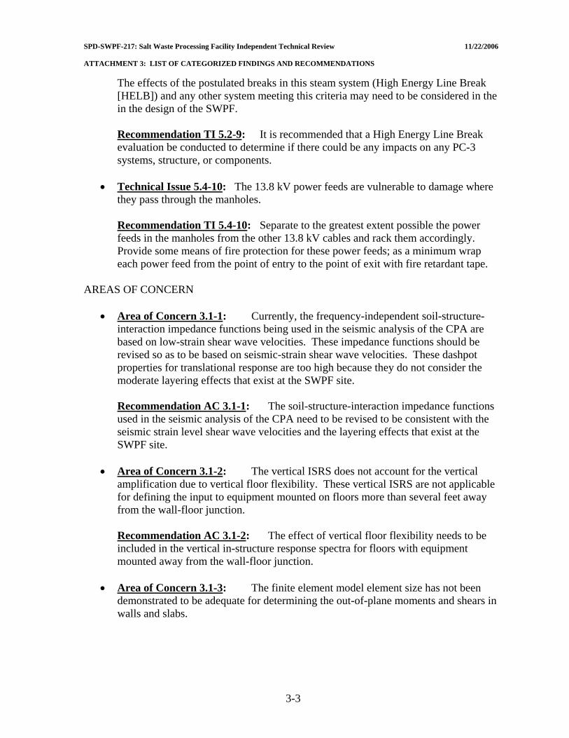
SPD-SWPF-217: Salt Waste Processing Facility Independent Technical Review 11/22/2006 ATTACHMENT 3: LIST OF CATEGORIZED FINDINGS AND RECOMMENDATIONS
The effects of the postulated breaks in this steam system (High Energy Line Break [HELB]) and any other system meeting this criteria may need to be considered in the in the design of the SWPF.
Recommendation TI 5.2-9: It is recommended that a High Energy Line Break evaluation be conducted to determine if there could be any impacts on any PC-3 systems, structure, or components.
• Technical Issue 5.4-10: The 13.8 kV power feeds are vulnerable to damage where
they pass through the manholes.
Recommendation TI 5.4-10: Separate to the greatest extent possible the power feeds in the manholes from the other 13.8 kV cables and rack them accordingly. Provide some means of fire protection for these power feeds; as a minimum wrap each power feed from the point of entry to the point of exit with fire retardant tape.
AREAS OF CONCERN
• Area of Concern 3.1-1: Currently, the frequency-independent soil-structure-interaction impedance functions being used in the seismic analysis of the CPA are based on low-strain shear wave velocities. These impedance functions should be revised so as to be based on seismic-strain shear wave velocities. These dashpot properties for translational response are too high because they do not consider the moderate layering effects that exist at the SWPF site.
Recommendation AC 3.1-1: The soil-structure-interaction impedance functions used in the seismic analysis of the CPA need to be revised to be consistent with the seismic strain level shear wave velocities and the layering effects that exist at the SWPF site.
• Area of Concern 3.1-2: The vertical ISRS does not account for the vertical
amplification due to vertical floor flexibility. These vertical ISRS are not applicable for defining the input to equipment mounted on floors more than several feet away from the wall-floor junction.
Recommendation AC 3.1-2: The effect of vertical floor flexibility needs to be included in the vertical in-structure response spectra for floors with equipment mounted away from the wall-floor junction.
• Area of Concern 3.1-3: The finite element model element size has not been
demonstrated to be adequate for determining the out-of-plane moments and shears in walls and slabs.
3-3
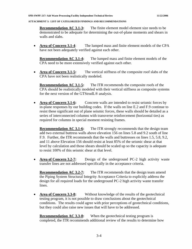
SPD-SWPF-217: Salt Waste Processing Facility Independent Technical Review 11/22/2006 ATTACHMENT 3: LIST OF CATEGORIZED FINDINGS AND RECOMMENDATIONS
Recommendation AC 3.1-3: The finite element model element size needs to be demonstrated to be adequate for determining the out-of-plane moments and shears in walls and slabs.
• Area of Concern 3.1-4: The lumped mass and finite element models of the CPA
have not been adequately verified against each other.
Recommendation AC 3.1-4: The lumped mass and finite element models of the CPA need to be more extensively verified against each other.
• Area of Concern 3.1-5: The vertical stiffness of the composite roof slabs of the
CPA have not been realistically modeled.
Recommendation AC 3.1-5: The ITR recommends the composite roofs of the CPA should be realistically modeled with their vertical stiffness as composite systems for the next version of the GTStrudL® analysis.
• Area of Concern 3.1-6: Concrete walls are intended to resist seismic forces by
in-plane responses by our building codes. If the walls on line E.2 and F.9 continue to resist these significant out of plane seismic forces, these walls should be detailed as a series of interconnected columns with transverse reinforcement (horizontal ties) as required for columns in special moment resisting frames.
Recommendation AC 3.1-6: The ITR strongly recommends that the design team add two external buttress walls above elevation 156 on lines 5.8 and 9.2 south of line F.9. Further, the ITR recommends that the walls and buttresses on lines 1.5, 5.8, 9.2, and 11 above Elevation 156 should resist at least 85% of the seismic shear at that level by calculation and those shears should be scaled up so the capacity is adequate to resist 100% of this seismic shear at that level.
• Area of Concern 3.2-7: Design of the underground PC-2 high activity waste
transfer lines are not addressed specifically in the acceptance criteria.
Recommendation AC 3.2-7: The ITR recommends that the design team amend the Piping System Structural Integrity Acceptance Criteria to explicitly address the design for all required loads for the underground PC-2 high activity waste transfer lines.
• Area of Concern 3.3-8: Without knowledge of the results of the geotechnical
testing program, it is not possible to draw conclusions about the geotechnical conditions. The results could agree with prior perceptions of geotechnical conditions, but they could also raise new issues that will have to be addressed.
Recommendation AC 3.3-8: When the geotechnical testing program is completed, the ITR recommends additional review of the results to determine how
3-4
SPD-SWPF-217: Salt Waste Processing Facility Independent Technical Review 11/22/2006 ATTACHMENT 3: LIST OF CATEGORIZED FINDINGS AND RECOMMENDATIONS
they affect the geotechnical aspects of the design or whether the results have impacts on other design considerations.
• Area of Concern 3.3-9: The assumed subsidence bowl used in the 35% level
design calculations may or may not be adequate to account for this potential hazard to the structure.
Recommendation AC 3.3-9: The ITR recommends the EPC re-evaluate the correctness of the predicted soft zone subsidence model once geotechnical data is available.
• Area of Concern 3.3-10: The current analysis uses a uniform 3 inch differential
settlement assumption for assessing the impact of dynamic settlement.
Recommendation AC 3.3-10: The ITR recommends the EPC provide estimates of the magnitudes and spatial distribution of differential ground settlement due to pore pressures generated at depth during seismic shaking using procedures and criteria that have been developed and applied elsewhere at the SRS.
• Area of Concern 4.1-11: Test plans do not include collection of data necessary to
estimate post-flushing dose rates.
Recommendation AC 4.1-11: Test plans should be updated to provide information relevant to anticipated holdup in SWPF systems and the effectiveness of system flushing.
• Area of Concern 4.1-12: The ALARA design requirements identified in PP-RP-
4501 are not specifically implemented as project design criteria.
Recommendation AC 4.1-12: Promulgate ALARA design requirements as project design criteria such that these are implemented by the design organization in the final design.
• Area of Concern 4.1-13: The ALARA design requirement for airborne
contamination in the workplace is inconsistent with 10 CFR 835.1002(c) in that it allows up to 10% of the Derived Air Concentration in occupied operating areas during normal operating conditions.
Recommendation: AC 4.1-13: The SWPF design requirement for airborne contamination should address compliance with the 10 CFR Part 835 requirement.
• Area of Concern 4.1-14: The SWPF project does not appear to have used
maintenance experience at facilities (both onsite and offsite) to help understand the maintenance worker dose that will be experienced at the plant.
3-5
SPD-SWPF-217: Salt Waste Processing Facility Independent Technical Review 11/22/2006 ATTACHMENT 3: LIST OF CATEGORIZED FINDINGS AND RECOMMENDATIONS
Recommendation AC 4.1-14: Complete an effort to identify, collect, and utilize information from facilities with similar materials to estimate the maintenance worker dose anticipated for the SWPF during the operational period of the facility.
• Area of Concern 4.2-15: The accessibility of the bridge crane for maintenance is
via a maintenance platform located at the East end of the Operating Deck. The method/equipment required for removing/lowering/lifting failed and replacement crane components from/to the maintenance platform is not evident within this stage of design document deliverables.
Recommendation AC 4.2-15: Install wall mounted jib crane(s) for lowering and hoisting bridge crane components. This is specific to the Operating Deck and AFF Bridge Cranes.
• Area of Concern 4.2-16: Adequate head room/crane hoist lifting range is not
evident in the AFF Area for removal/replacement of the process vessel mounted agitators.
Recommendation AC 4.2-16: Determine headroom required to remove agitator(s) assemblies from the process vessel(s). Adjust crane hoist lift height and/or agitator mounting height so to remove from process vessel(s) in one assembly.
• Area of Concern 4.2-17: It is not evident from existing design documentation
whether the failed contactor components, agitators, and Hot Cell components will be bagged or containerized for transportation. If any contaminated components that are not packaged or containerized are moved about the Process Building, the spread of radioactive contamination is considered probable.
Recommendation AC 4.2-17: All failed equipment components (from radiation zones) should be containerized upon removal/prior to transportation, to eliminate personnel time in bagging and the possible spread of contamination during bagging. In most cases, contaminated components will require containerization prior to transporting to the burial vaults.
• Area of Concern 4.2-18: Other than on the Operating Deck, Transport Carts are
used extensively to move equipment components in/out of various Radiation Zones to Radiation Buffer Areas for repair or disposal. Many of these Radiation Zones are High Radiation Areas, downgraded to Radiation Areas. The spread of radioactive contamination is considered probable, specifically from the transport carts/wheels and forklift wheels.
Recommendation AC 4.2-18: Procedures should be developed for cleaning and maintaining clean wheels and/or placement of disposal floor coverings that are removed and disposed of after transportation activities.
3-6

SPD-SWPF-217: Salt Waste Processing Facility Independent Technical Review 11/22/2006 ATTACHMENT 3: LIST OF CATEGORIZED FINDINGS AND RECOMMENDATIONS
• Area of Concern 4.3-19: There is a significant inconsistency between the approved contract scope and the current design scope that represents a risk with respect to meeting the intent of the guiding principles of integrated safety management.
Recommendation AC 4.3-19: The contract scope should be reviewed and updated to be consistent with the current design scope.
• Area of Concern 4.4-20: Procedure PP-EN-5004 Revision 3 does not identify all
needed software quality assurance requirements.
Recommendation AC 4.4-20: Revise software procedure PP-EN-5004 to: (1) require identification of the approved operating environment for software that has been verified and validated and that the software was used within the parameters that it has been verified and validated for, (2) indicate whether software is single use or not, and (3) establish a mechanism to assure no design activities are performed using a computer program that is in question.
• Area of Concern 4.4-21: The software management program is not fully
understood and implemented.
Recommendation AC 4.4-21: It is recommended that: (1) computer programs created using applications such as iGrafx® be identified in the software registry and verified and validated (V&V) as appropriate, (2) confirm that verification and validation results and user environments are equivalent for all calculations, revise V&V results if necessary, and (3) consider conducting additional training for personnel.
• Area of Concern 5.1-22: During the review of the PFDs/P&IDs the design only
provided for vacuum protection with a relief valve on the common header. Although redundant relief valves are provided, this is considered insufficient protection for the number of vessels and tanks in the dark cell.
Recommendation AC 5.1-22: Design the vessels/tanks for full vacuum. The additional cost will eliminate a large economic risk.
• Area of Concern 5.1-23: The methods for sizing lines and pumps are for clear
fluids only.
Recommendation AC 5.1-23: All lines should be checked to see that minimum transport velocity is exceeded for waste sludge and MST based on their particle sizes and density.
• Area of Concern 5.1-24: The flushing velocity is too low and is often less than
the transport velocity. The flush velocity serves two purposes; to wash and dissolve
3-7
SPD-SWPF-217: Salt Waste Processing Facility Independent Technical Review 11/22/2006 ATTACHMENT 3: LIST OF CATEGORIZED FINDINGS AND RECOMMENDATIONS
any residual and to remove any particulates left behind. To remove any insoluble solids left behind, it is necessary to run at a higher velocity than the velocity which left the particles behind. To minimize the wash volume, high velocities are required.
Recommendation AC 5.1-24: The flush velocity should be greater than 4 ft/sec and greater than the minimum transport velocity. A practical number is 10 ft/sec.
• Area of Concern 5.1-25: The only specification of a low shear system is for
pumps.
Recommendation AC 5.1-25: To minimize attrition damage to the particles that could impact filtration rate, the entire system must be evaluated based on power input and time to develop equipment and strategies to minimize loss of filtration rate.
• Area of Concern 5.1-26: The definition of mixing equipment for solids
suspension is typically based on physical properties such as solids and liquid density, particle size and distribution, concentration and liquid viscosity. In the test results, hardly any of these properties are given (though in most cases they are known). Success was based on the ability to handle simulants. Little or no justification is given for the use of these simulants. Kaolin clay slurries are typically used as a rheological simulant not as a settling particle simulant.
Recommendation AC 5.1-26: Expert input for future tests on process mixing is needed and should include: more physical properties need to be recorded during these tests, simulants similar in physical properties to those expected need to be used, and the liquid blend time should be measured.
• Area of Concern 5.1-27: The geometry chosen was similar to AEA Technology
design. Testing allowed some optimization which leads to better design. The range of parameters tested was only acceptable for a demonstration and first cut design.
Recommendation AC 5.1-27: Future testing must use a more realistic simulant than kaolin clay. Liquid phase blend time needs to be measured, and zone of influence needs to be determined. A model based on physical and fluid dynamic properties needs to be developed. A technical exchange with the WTP team at Bechtel and Battelle would be useful as they also are developing a test plan to determine similar information.
• Area of Concern 5.1-28: Fine particulate solids can adversely affect coalescing
and mass transfer devices. The particles gather at the liquid-liquid interface and reduce coalescence leading to smaller drops and higher carryover. In the worst case they can form a thick emulsion band and lead to the formation at interfaces of a viscous rag layer.
3-8

SPD-SWPF-217: Salt Waste Processing Facility Independent Technical Review 11/22/2006 ATTACHMENT 3: LIST OF CATEGORIZED FINDINGS AND RECOMMENDATIONS
Recommendation AC 5.1-28: It is recommended that the organics be continuous or periodically cleaned of any particulates that may form in the organics due to decomposition. These particulates could interfere with the separation and increase carryover.
• Area of Concern 5.2-29: Currently, due to low velocities and flow rates it is
believed the cross flow filters will not be subject to any Flow Induced Vibration (FIV). There is no empirical or test data to support this assumption. The ITR understands the EPC is currently planning to conduct flow and particulate performance testing for the cross flow filters.
Recommendation AC 5.2-29: As part of this testing, the ITR recommends data should be obtained to determine if the filters can be subjected to flow induced vibration. It is also recommended that the Mechanical and Piping Groups should have an integral part in the design of the design and implementation of the test program.
• Area of Concern 5.2-30: The assumption made in the qualification of PC-1 and
PC-3 pumps that are designed to commercial standards is that a DBE will not challenge the pressure boundary integrity of the pump case, and therefore no specific evaluation of the pump case pressure boundary for DBE loads will be required. The pump nozzles and anchorage will be evaluated for applied seismic loads but there will be no explicit evaluation of any seismic-induced stresses in the pump case from the DBE event.
Recommendation AC 5.2-30: A list of pump qualification criteria are recommended for use by the EPC.
• Area of Concern 5.2-31: Previous DOE experience in mechanical equipment
procurements has shown that without concise guidance, the vendor qualifications methods and the technical acceptability of the qualification efforts will vary significantly. Further, it could be anticipated that, in some cases, the qualification calculations and reports will not meet the SWPF design basis methods or criteria.
Recommendation AC 5.2-31: The ITR recommends that the mechanical equipment qualification specifications should be reviewed and updated for consistency, conciseness, and to provide more definitive guidance to the vendors.
• Area of Concern 5.2-32: In addition, none of the specifications that are marked
safety significant (SS) evoke ASME NQA-1, and there is also inconsistently in the specification of quality assurance requirements.
Recommendation AC 5.2-32: The ITR recommends that the specifications need to be updated to incorporate NQA-1 and to ensure consistent quality assurance requirements.
3-9
SPD-SWPF-217: Salt Waste Processing Facility Independent Technical Review 11/22/2006 ATTACHMENT 3: LIST OF CATEGORIZED FINDINGS AND RECOMMENDATIONS
• Area of Concern 5.2-33: Currently the ASME Section VIII pressure vessels in the dark cells are being specified as “Lethal Service” which ensures essentially 100% Radiographic Testing inspection (RT) of all butt welds and most other pressure retaining welds on the vessels. There are some possible exceptions to this in ASME BPVC Section VIII, Division 1, Subsection UW and some welds that cannot be examined by RT. This specification of 100% RT is not the case for other components in the dark cells such as filters. The base mechanical design criteria (G-ESR-J-00003) implies the 100% RT is required for all pressure retaining welds on process equipment in the dark cells, in fact it expands the 100% RT requirement to all PC-3 equipment.
Recommendation AC 5.2-33: It is recommended that the following weld inspection criteria should be clearly called out for all pressure retaining equipment located in dark cells and possibly all PC-3 equipment.
• Area of Concern 5.2-34: As with PC-3 vessels the base code of record for these
vessels is the ASME BPVC Section VIII, Division 1. Section VIII, Division 1 does not provide sufficient guidance to address all the loading conditions to which these vessels are being designed.
Recommendation AC 5.2-34: The ITR recommends that specific load combination equations with associated stress capacities be provided and reference to the appropriate code sections.
• Area of Concern 5.2-35: One potential non-conservatism in the seismic design
criteria would be the use of IP = 1.0 for some of the PC-1 components. Per ASCE 7-02, Section 9.6.1.5 IP = 1.5 for components with hazardous materials; it would seem many PC-1 piping systems (Cold Chemicals Area) will contain hazardous materials of one type or another.
Recommendation AC 5.2-35: The ITR recommends that IP should be taken as 1.5 not 1.0 for many of these systems. In should be noted that for the PC-1, -2 vessels containing similar materials an Ip =1.5 is being used.
• Area of Concern 5.2-36: Based on discussions with the EPC staff, it appears the
pipe support design may be split between the Piping Group and the Civil Structural Group. Standard Component Support items (Clamps, hangers, straps, etc.) would be designed and specified by the piping group and supporting structural steel, pipe rack type supports, and support anchorages will be designed by the Structural Group. It is possible there could be inconsistencies in load combinations, inelastic energy adsorption factors, and allowable capacities between the Structural Design Codes and the B31.3 Code.
3-10
SPD-SWPF-217: Salt Waste Processing Facility Independent Technical Review 11/22/2006 ATTACHMENT 3: LIST OF CATEGORIZED FINDINGS AND RECOMMENDATIONS
Recommendation AC 5.2-36: The ITR recommends that a specific integrated criteria for design of all pipe support members be developed and added to the Mechanical or the Structural design criteria. Such a criterion would define the demand, capacity and load combinations to be used for all aspects of pipe support design. This would preclude any possible inconsistencies in the pipe support design requirements and methods.
• Area of Concern 5.2-37: This fire protection designation as General Service and
PC-1 would seem to be in conflict with the DOE Interim Safety Guidance. Designating the fire protection systems as safety (SC or SS) systems will have a significant impact on the current design. Review of the design specifications and the system design description suggests that the designs are consistent with the referenced DOE and NFPA standards.
Recommendation AC 5.2-37: The apparent discrepancy between the current design and the DOE Interim Safety Guidance must be resolved as soon as possible.
• Area of Concern 5.2-38: Erosion concerns were identified in process tanks
TK-101 and TK-102. Both tanks process a MST/high-level waste slurry. This slurry contains approximately 600 mg/liter suspended solids. The APAs are mounted on the tank inside wall and extend downward to near the bottom head. The impact velocity at the bottom of the head is estimated to be 20-50 fps. It is unclear if wear plates are to be installed to protect the bottom head from erosion.
Recommendation AC 5.2-38: A final decision and the development of a supporting technical basis on the need for wear plates must be made prior to completion of specifications for procurement of vessels and tanks.
• Area of Concern 5.2-39: The current seismic design of mechanical equipment
and piping systems is based on preliminary amplified floor response spectra that were generated from a simplified lumped mass linear elastic model. The spectra are very broad and contain a 15% bump factor on the spectra peaks. There are several ongoing seismic issues that could impact the spectra and the seismic design of mechanical equipment and piping.
Recommendation AC 5.2-39: The design and analysis of mechanical components and distribution (piping) systems must be re-evaluated if any changes occur in soil properties, floor response spectra, and structural analysis.
• Area of Concern 5.2-40: To date, the only non-normal loads (normal being
weight and thermal expansion) being considered by the EPC in the design of mechanical equipment and piping systems. They are the NPH of wind and earthquake. Based on limited discussions with the EPC, it would appear that other possible accident scenarios may not have been considered at this point in the design.
3-11

SPD-SWPF-217: Salt Waste Processing Facility Independent Technical Review 11/22/2006 ATTACHMENT 3: LIST OF CATEGORIZED FINDINGS AND RECOMMENDATIONS
Recommendation AC 5.2-40: The ITR recommends that the EPC determine whether other possible accident scenarios should be considered in the equipment design.
• Area of Concern 5.3-41: Intended functions of the Central Process Area (CPA)
confinement system to contain hazardous materials and monitor hazardous material releases may be compromised due to General Service classification where exhaust duct header exits the CPA boundary and discharges through the exhaust stack. In particular, this portion of the exhaust header is at positive pressure and runs through occupied non-radiological maintenance areas in the Eastern Facility Support Area.
Recommendation AC 5.3-41: The confinement function of the exhaust duct header for mitigating a hazardous material release should be verified.
• Area of Concern 5.4-42: The overhead electrical system upstream of ELNA-SW-
102 cannot handle the plant load when 13.8 kV feeder “A” is not available.
Recommendation AC 5.4-42: Redesign the overhead electrical system that conveys 13.8 kV power to the SWPF via isolating switch ELNA-SW-102 so that the maximum demand of 6,435 kVA can be accommodated. This change will also solve the voltage drop problem that exists.
• Area of Concern 5.4-43: Transformers XFMR-101, XFMR-102, XFMR-103,
XFMR-104, XFMR-106, and XFMR-107 are overloaded or are at near overload conditions in the scenario where a 13.8 kV switchgear or associated transformers are out of service.
Recommendation AC 5.4-43: Re-evaluate transformer sizing with considerations given to the required 20% spare capacity and the validity of the required loads identified at this stage of the project. Transformer size increases or the use of forced cooling of existing transformers are possible solutions if overloads are confirmed.
• Area of Concern 5.4-44: The Standby Diesel Generator can reach an overloaded
condition.
Recommendation AC 5.4-44: Specify in document P-DB-J-00004 at what point in time in the project the 20% spare capacity for the SDG applies. Re-evaluate the SDG sizing with considerations given to the required 20% spare capacity and the validity of the required loads identified at this stage of the project.
• Area of Concern 5.5-45: The SWPF Project Procedure PP-GN-1017, Computer
Software Management, does not apply to I&C systems. There are no other procedures which address software quality assurance for I&C systems. This will be an issue for the project based on the history of the DNFSB and DOE on projects over the last ten years.
3-12
SPD-SWPF-217: Salt Waste Processing Facility Independent Technical Review 11/22/2006 ATTACHMENT 3: LIST OF CATEGORIZED FINDINGS AND RECOMMENDATIONS
Recommendation AC 5.5-45: It is recommended that a set of procedures and practices be developed that specifically address software quality assurance for I&C systems. An area of particular importance in these procedures is Configuration Management of I&C Software and testing for unintended functions. All software used for design purposes should follow PP-GN-1017.
• Area of Concern 5.5-46: The defined design process for Safety Significant
Instrumented Systems (SSIS) is that specified in ANSI/ISA 84.00.01-2004. This design approach defines a failure on demand requirement for a system which is based on the probability of occurrence and consequence of a particular event. This is an accepted approach in DOE complex. However, SWPF plans to purchase all instrumentation with a Safety Integrity Level II.
Recommendation AC 5.5-46: It is recommended that the calculations indicated in ISA 84.00-01-2004 be performed for each SSIS and that the system failure on demand with the selected equipment be determined. This would provide the documentation required to defend the designed systems.
• Area of Concern 5.5-47: The current design includes a switch that detects a
seismic event of a defined magnitude and initiates protective actions. The existence of a reliable switch is questionable. SRS has been evaluating switches for this type of an event for the past few years. SWPF should obtain the result of the SRS evaluations.
Recommendation AC 5.5-47: SRS has been looking at such switches for several years. The project should obtain the SRS information for evaluation of applicability to the project.
• Area of Concern 5.5-48: The present design includes a number of plug valves
with operators which must be seismically qualified. The I&C organization is responsible for writing the procurement specification for these valves with appropriate input on the applicable response spectrum and anticipated supports. The vendor is expected to supply a qualified valve.
Recommendation AC 5.5-48: There are a number of plug valves with operators and manually operated valves of the same basic design which must be seismically qualified. These valves should be combined in a single procurement to enhance the ability to attract qualified vendors.
SUGGESTED IMPROVEMENTS
• Suggested Improvement 3.2-1: It is suggested that the PC-2 underground waste transfer lines be constructed using full penetration, butt welded ductile steel piping. This recommendation is based upon field experience where it has been consistently
3-13
SPD-SWPF-217: Salt Waste Processing Facility Independent Technical Review 11/22/2006 ATTACHMENT 3: LIST OF CATEGORIZED FINDINGS AND RECOMMENDATIONS
shown that full penetration, butt welded ductile piping can accommodate very large deformations without failure.
• Suggested Improvement 3.4-2: Three risks, previously unidentified, were defined
by the ITR for incorporation into the SWPF Risk Assessment and Management Plan for purposes of developing mitigation strategies, tracking, and regular follow up. They are: (a) the risk to design of moving forward without final geotechnical data, (b) the risk to in-structure response spectra of moving forward without final geotechnical data, and (c) the risk to cost and schedule arising from the change from ISO-9001 to NQA-1 quality standard.
• Suggested Improvement 4.1-3: It is suggested that the radiological optimization
process be more formally applied in the Final Design.
• Suggested Improvement 4.1-4: It is suggested that the preferred approach is to use the shielding software in a manner that most realistically represents the physical conditions. Then, for borderline cases of calculated shield thickness, a safety factor should be then added to the analytical result to make sure the shield is sufficient.
• Suggested Improvement 4.1-5: It is suggested that the EPC commit to a formal
test procedure to confirm the radiation shielding in areas where low dose rates must be achieved prior to and during initial operations.
• Suggested Improvement 4.1-6: Preliminary dose estimates have been conducted
for labyrinth entrances and based on those results, location of piping and other components within the pump rooms are being revised. A task has been initiated to calculate labyrinth entrance doses using the MCNP Monte-Carlo code. It is suggested that an independent technical review of the labyrinths calculations and design when their design is close to being finalized.
• Suggested Improvement 4.1-7: It is suggested that MCNP be formally qualified
locally for later use when penetration designs are being finalized.
• Suggested Improvement 4.2-8: Equipment and equipment locations have not been determined within the Hot Cell. Therefore, the planned operating envelop of the Hot Cell crane cannot be confirmed relative to operations and maintenance support of the in-cell equipment. Crane operating envelop with respect to in-cell equipment should be addressed in future design activities.
• Suggested Improvement 4.2-9: Bridge crane design capacities are given without
reference data for estimated weights of hoisted equipment/components. This should be addressed prior to equipment specification and procurement activities.
• Suggested Improvement 4.2-10: Equipment assemblies should be designed in a
modular concept form, with quick disconnect anchor attachments, couplings, etc., to
3-14

SPD-SWPF-217: Salt Waste Processing Facility Independent Technical Review 11/22/2006 ATTACHMENT 3: LIST OF CATEGORIZED FINDINGS AND RECOMMENDATIONS
minimize personnel time within containment/radiation zones during equipment removal and replacement. It is suggested that the EPC review the modular equipment designs used and presently in service at SRS.
• Suggested Improvement 4.2-11: Transport Carts have been sized with design
transported tonnage stated without reference data for equipment loads being transported. Equipment loads should be addressed prior to specification and procurement activities.
• Suggested Improvement 4.2-12: Adequate clear space to access and remove
equipment items by the Monorail Hoists and Transport Carts is not evident and should be addressed in future design activities.
• Suggested Improvement 4.2-13: Monorail Hoist Assemblies have been sized with
design lifting tonnage stated without reference data for hoisted equipment weights. Hoisted equipment weights should be addressed prior to specification and procurement activities.
• Suggested Improvement 4.2-14: Method of penetration of Hot Cell Conveyor,
through Hot Cell wall to allow material transfer/sample pig access, without allowing radiation/contamination release into the Laboratory is not evident within the design documents. This issue must be addressed in final design.
• Suggested Improvement 4.2-15: Hot Cell access for conveyor maintenance
activities is not evident within the design documents and must be addressed in final design.
• Suggested Improvement 4.3-16: The PDSA Chapter 10 (testing) and the Chapter
17 (organization and qualification) are minimally acceptable and need to be augmented to ensure that operator training includes the feedback and lessons learned from component testing and initial startup testing.
• Suggested Improvement 4.4-17: As the NQA-1 program becomes fully
implemented more NQA-1 compliant audits will need to be performed.
• Suggested Improvement 4.4-18: Continue planned effort using an outside QA resource to evaluate the impacts of conversion to NQA-1 on completed design work.
• Suggested Improvement 5.1-19: These documents[1– 7] also contain “assumptions”
which will need to be closed and assurances should be established that these assumptions are valid or will not affect the preliminary design significantly. The EPC should prepare a document which lists the updated status of these assumptions in the documents or revise the documents with statements which are more up-to-date.
3-15
SPD-SWPF-217: Salt Waste Processing Facility Independent Technical Review 11/22/2006 ATTACHMENT 3: LIST OF CATEGORIZED FINDINGS AND RECOMMENDATIONS
• Suggested Improvement 5.1-20: For personnel not familiar with the project scope it would be beneficial to identify the scope on the PFD (page 3 of the functional specification) which appears in several documents. This could be similar format [dotted lines] as utilized in Figure 1-1 of this document to distinguish the scope between Alpha Strike, Cesium Removal, and Alpha Finishing.
• Suggested Improvement 5.1-21: The discussion in Section 3.4 of the Process Basis
of Design (regarding the Cold Chemicals Area) should identify all safety concerns. Since the facility and process use acid and caustic, the danger of mixing acid and caustic needs to be identified. The SWPF Process Basis of Design should also quantify the “shielding requirements”.
• Suggested Improvement 5.1-22: The Design Criteria Database is not thorough and
does not describe its purpose and its utilization. It is not consistent with the S/RID document. The EPC is encouraged to include a discussion in the document regarding the purpose of the document and how it is to be utilized by project staff. The document should be upgraded for consistency with the SWPF S/RID.
• Suggested Improvement 5.1-23: It is suggested that the EPC provide updated
model runs (as planned) using more recent design data. One source of design data to be incorporated is the centrifugal contactors failure data discussed in Section 5.1.1.13. When doing the additional model runs, the EPC should consider adding interface availabilities and the need for re-sampling, if samples are rejected or mis-analyzed.
• Suggested Improvement 5.1-24: The Design Process Description provides a good
roadmap for establishing a firm foundation for design and the implementation of the design. It is suggested that the EPC utilize the document to create a “checklist” for making sure the plans described in the document are implemented.
• Suggested Improvement 5.1-25: Coalescence pads are notorious for also being
very good filters. Thus, every effort must be made to keep solids out of the system. It is suggested that the design take into account that these units may need frequent change outs of the coalescence medium, particularly after process upsets.
• Suggested Improvement 5.1-26: Some users of cross-flow filter units have been
able to develop heuristic models of the performance based on measured flows and pressure drops to determine when flushes are needed. It is suggested that the EPC develop a heuristic model between flow rate and pressure drop as a useful guide for operation.
• Suggested Improvement 5.2-27: It is suggested that the EPC revise and update all
the specifications sheets for the vessels with APAs, when the APA design is finalized.
• Suggested Improvement 5.2-28: None of the PC-3 specification sheets have the design basis amplified floor response spectra attached to them. This would be
3-16

SPD-SWPF-217: Salt Waste Processing Facility Independent Technical Review 11/22/2006 ATTACHMENT 3: LIST OF CATEGORIZED FINDINGS AND RECOMMENDATIONS
expected at this stage in the design as the Civil-Structural Group is still developing the final amplified floor response spectra for this project. It is suggested that all PC-3 component specification sheets be revised to incorporate the amplified floor spectra to be used in the design and qualification.
• Suggested Improvement 5.2-29: It is suggested that in addition to the fluid test
data, the APA test should be instrumented to also obtain structural, fluid sloshing, and vibration data.
• Suggested Improvement 5.2-30: The recently issued version of the P&IDs
incorporated changes in function, equipment, and systems operation for some systems. These changes will require modification to the plant arrangement (equipment location) and to piping systems. It is suggested that the EPC review of P&ID changes and ensure incorporation of all changes in General Arrangement drawings and Piping Area drawings.
• Suggested Improvement 5.2-31: While the base code of record for these vessels is
the ASME BPVC Section VIII, Division 1. Section VIII, Division 1 does not provide sufficient guidance to address all the loading conditions to which these vessels are being designed. Because of the use of hybrid criteria, it is suggested that more definitive load combinations and acceptance criteria should be provided especially in the specification to the vendors. The ITR suggests that specific load combination equations with associated stress capacities be provided and reference to the appropriate code sections.
• Suggested Improvement 5.2-32: Atmosphere storage tanks are being designed to
API-650 which is an acceptable standard for use on the SWPF. All such tanks are classified as PC-1 and the base tanks specification (11812) references 11819 for seismic design but specifically states fluid structure interaction effects during a seismic event must be evaluated. The seismic design basis for PC-1 components is DOE-STD-1020 -2002 which via the Uniform Building Code requires the use of ASCE 7-02 for seismic design. The ITR suggests that ASCE 7-02, Section 9.14.7.3 be specified for the seismic design of these tanks.
• Suggested Improvement 5.2-33: The ITR suggests that some additional piping
criteria items need to be reviewed, clarified and possibly additional guidance provided in the piping design basis criteria to ensure that they are adequately addressed.
• Suggested Improvement 5.2-34: It was not clear from the analyses reviewed
whether corroded or uncorroded pipe properties were being used for the evaluation of sustained loads. B31.3 implies as does the SWPF piping design criteria that corroded properties should be used. The EPC should verify that corroded pipe properties are being used for the evaluation of sustained loads.
3-17
SPD-SWPF-217: Salt Waste Processing Facility Independent Technical Review 11/22/2006 ATTACHMENT 3: LIST OF CATEGORIZED FINDINGS AND RECOMMENDATIONS
• Suggested Improvement 5.2-35: There are some additional items in the material specifications that should be reviewed, clarified and possibly additional guidance provided in the piping specifications currently issued to ensure that they are consistent with the plant design basis.
• Suggested Improvement 5.2-36: Currently, the EPC has stated they intend to use
only butt welded piping connections in the dark cells. In addition, the EPC is supporting all non PC-3 piping in dark cells to the PC-3 seismic criteria, which is considered prudent by the ITR. However, a formal method of implementation and control of these requirements in the dark cells is under review and has not yet been defined. All the piping material class sheets reviewed in Specification 15120 would at least permit sockets. If the intention is to not permit socket welds in the dark cells, the ITR suggests a more definitive control mechanism.
• Suggested Improvement 5.2-37: These specifications classify these components as
PC-1, but no seismic design guidance is given. Per discussion with the EPC Piping Group (the specifications are actually the responsibility of the HVAC group) it is believed that this is an incorrect specification. The ITR suggests that these items should be classified as PC-0.
• Suggested Improvement 5.2-38: The uncertainties associated with the oxalic
corrosion test data should be addressed in order to determine the conservatism associated with the corrosion allowance specified for tanks TK-127 and TK-106 and the nominal corrosion rates estimated in the GA study.
• Suggested Improvement 5.2-39: The report states that these data were derived
from tests that included agitation but no intentional aeration; yet, it does not discuss the relevancy of this data to SWPF tanks that are agitated by APAs. It is suggested that the relevancy of this data to SWPF tanks with APAs, should be discussed.
• Suggested Improvement 5.2-40: Since the degree of sensitization in low carbon
300 series stainless steel (Types 316L and 304L) used in SWPF tanks is low and a basic pH is maintained in the tanks, chloride induced stress corrosion cracking should not be a concern. However, the process is time dependent and material properties and fabrication practices can significantly affect SCC susceptibility in these materials. Therefore, it is suggested that where possible, periodic NDE weld inspections should be performed during the operating life of these components.
• Suggested Improvement 5.2-41: The best protection against crevice corrosion is to
ensure that the tank design and fabrication processes will not create any crevice conditions on the wetted surfaces of the tanks. Since the presence of oxygen can increase the potential for crevice corrosion, special care to eliminate any crevice conditions is especially important for those tanks agitated by APAs.
3-18
SPD-SWPF-217: Salt Waste Processing Facility Independent Technical Review 11/22/2006 ATTACHMENT 3: LIST OF CATEGORIZED FINDINGS AND RECOMMENDATIONS
• Suggested Improvement 5.3-42: Functional classification assignments on some calculations are not consistent with functional classifications described in source documents and shown on HVAC Airflow and Control Drawings. It is suggested that the EPC verify calculation functional classifications and correct as required.
• Suggested Improvement 5.3-43: For the AFF, the integrity and leak-tightness of
the PC-1 building structure may impact continued operability of the ventilation system to maintain negative differential pressures for contamination control during process upset events such as high winds, or a breach of the structure. It is suggested that the confinement system requirements of the AFF structures and ventilation system should be addressed in more detail during development of PDSA.
• Suggested Improvement 5.4-44: It is suggested that calculation E-CLC-J-00028 be
revised when there are significant load changes or when operating conditions are more defined so that the maximum electrical demand information can be kept current. A schedule for regular updates is also suggested.
• Suggested Improvement 5.4-45: A loss of power to the Administration Building
can occur if 13.8 kV feeder “B” is inactive. It is suggested that the EPC document the fact that a loss of power to the Administration Building can occur if 13.8 kV feeder “B” is inactive and that this be added to the document System Number 1000 Electrical, System Design Description E-SYD-J-00001 and other appropriate documents.
• Suggested Improvement 5.4-46: Electrical design input from SRS has not always
been obtained through the process outlined in the Quality Assurance Plan. It is suggested that the EPC request the SRS electrical design input information be provided in accordance with the Quality Assurance Plan.
• Suggested Improvement 5.4-47: It is suggested that the EPC specify in P-DB-J-
00004 spare capacities for 480 V switchgears and power transformers. Also, it should be specified at what point in time in the project the spare capacities apply. In addition, it is suggested that the single line diagrams should show the spares and the physical drawings, where appropriate, should show the additional space occupied due to the spare capacity.
• Suggested Improvement 5.4-48: In a situation where a tornado disables both the
normal and standby electrical equipment, it may not be possible to connect the portable generator as another source of power. It is suggested that the EPC evaluate the situation to determine if other appropriate measures need to be developed to address the possibility of not being able to utilize the portable generator as a source of power. It is further suggested that the EPC document the outcome of the evaluation.
• Suggested Improvement 5.4-49: Calculations have not been performed to support
all issued electrical design. It is suggested that the EPC perform calculations to
3-19
SPD-SWPF-217: Salt Waste Processing Facility Independent Technical Review 11/22/2006 ATTACHMENT 3: LIST OF CATEGORIZED FINDINGS AND RECOMMENDATIONS
support the issued designs as follows: harmonic content, grounding grid, duct ban/manholes, and lighting.
• Suggested Improvement 5.4-50: Only ducts for 13.8 kV cables have been shown in
duct banks. It is suggested that the EPC re-evaluate the duct banks need for ducts of other cables besides 13.8 kV e.g., 480 V power or control. Also, which ducts are to be used for construction cables should be established.
• Suggested Improvement 5.4-51: There are neither profiles for duct banks nor
coordinates for manholes. It is suggested that this be coordinated with the EPC Civil Group to establish both the profiles and the coordinates for the duct banks/manholes.
• Suggested Improvement 5.4-52: The conduit system to convey standby power
from the main electrical room to the AFF electrical room is not shown. The EPC should develop the conduit system for the AFF standby power and show it on the relevant drawings.
• Suggested Improvement 5.4-53: There are no calculations to support the lightning
protection designs. Since DWPF has operated very successfully over the years with the lightning protection that they installed, it is suggested that the EPC give serious consideration needs to be given to applying this system on SWPF.
• Suggested Improvement 5.4-54: It is suggested that the EPC prepare an Electrical
Design Criteria document to include the criteria applicable to this project. Examples of criteria to be included: voltages and tolerances at each bus and at each load, the fact that all uninterrupted power supply cables are to be run in conduits, illumination levels for each room/area, and spare electrical capacities for electrical equipment and how applied.
• Suggested Improvement 5.4-55: It is suggested that the EPC develop criteria for
the cable tray system. The suggested cable tray criteria should address: trays for power and control cabling (only power trays are shown now); separation of redundant cables within a tray or the use of separate trays; the handling of “large” and “small” cables within tray; the potential of damage due to “two over one” situations (e.g., the damage of both redundant cables); the requirement of showing locating dimensions and elevations on drawings.
• Suggested Improvement 5.4-56: An automated system is not being utilized for
circuit and raceway scheduling. It is suggested that the EPC evaluate the need for an automated system for the circuit and raceway scheduling with consideration been given to the SRS standard program (PDMS).
• Suggested Improvement 5.5-57: SRS has adopted site standard equipment that
have existing procurement contracts. The project has selected the site standard
3-20

SPD-SWPF-217: Salt Waste Processing Facility Independent Technical Review 11/22/2006 ATTACHMENT 3: LIST OF CATEGORIZED FINDINGS AND RECOMMENDATIONS
Distributed Control System but there are many other site standard components which should be investigated for use on the project.
• Suggested Improvement 5.5-58: It is suggested that the EPC develop a set of
procedures and practices for the I&C systems which may include the software quality assurance issues identified above and the design criteria and requirements that apply.
• Suggested Improvement 5.5-59: SWPF Project Procedure PP-NS-5501, Functional
Classification Methodology, defines five functional classifications and the criteria for each. In the Balance of Plant Basis of Design document, a classification “important to safety” is mentioned. It is suggested that this term be removed from the Balance of Plant Basis of Design document and replaced with the appropriate one of the five functional classifications.
• Suggested Improvement 5.5-60: The functional classification of the
instrumentation used to monitor parameters which are initial conditions for the safety analysis is not consistent with nuclear industry practice. It is suggested that the functional classification be done consistent with the nuclear industry practice. This should result in the lowering of the current functional classification.
• Suggested Improvement 5.5-61: It is suggested that the EPC review plant
simulator efforts at WTP and SRS before selecting the simulator platform, the mathematical models, and the physical properties database.
• Suggested Improvement 5.5-62: SRS has been evaluating the performance of
contactors as part of a waste processing process for several years. Part of this evaluation included the development of a mathematical model of a contactor. This project should obtain and evaluate the SRS model before developing the simulator models.
• Suggested Improvement 5.5-63: The project has committed to applying NUREG-
0700 to the design of the man machine interface. SRS has developed a computer program that can identify the applicable requirements from NUREG-0700 for a specific project.
• Suggested Improvement 5.5-64: In several discussions with the EPC I&C
organization, issues such as automated operating procedures which require operations input were identified. Many of the decisions in the design of the plant control and information system have a significant impact on plant operations. The design of the man-machine interface, operational sequencing and other Distributed Control System operation functions require the participation of Operations. It is suggested that the EPC involve the plant operations staff in the design of the I&C system.
• Suggested Improvement 5.7-65: It is suggested that the EPC line the interior floor,
walls, and ceiling of the laboratory hot cell with stainless steel to the maximum
3-21

SPD-SWPF-217: Salt Waste Processing Facility Independent Technical Review 11/22/2006 ATTACHMENT 3: LIST OF CATEGORIZED FINDINGS AND RECOMMENDATIONS
degree practicable. It is also suggested that the EPC add requirements on design of piping systems for flushing and on coatings for decontamination into the appropriate basis of design documents.
• Suggested Improvement 5.7-66: Dose reduction design features for normal
operations are also useful for D&D. This includes pipe flushing, coatings on surfaces to enhance the ability to decontaminate, and avoidance of crud traps. These subjects are addressed in the ALARA review procedure and are apparently subject of design practice in some cases. The EPC should develop written design requirements or guidance related to flushing, coatings, and avoidance of crud traps.
• Suggested Improvement 5.7-67: For future D&D planning, the EPC should
consider developing a comprehensive photographic record during construction and cold operations that captures features which will not be visible or accessible in the future. This would include video and/or photographs of the rebar for foundations and heavy walls before pouring concrete, the underground excavation before backfilling after the lower part of the building is in place, and inside all the dark cells.
POSITIVE FINDINGS
• Positive Finding 4.1-1: The SWPF laboratory preliminary design is well developed for anticipated sample nature and load.
• Positive Finding 4.1-2: The EPC ESH&Q Organization’s capability was
reviewed with regard to the software and users for analyzing shielding design. MicroShield® is an excellent choice for much of the analyses and calculations that are needed to conform the SWPF design to 10 CFR 835. The lead analyst applying the software has an excellent depth of experience, having used MicroShield® for past projects.
• Positive Finding 4.1-3: Shielding calculations were reviewed and an independent
calculation was conducted. The bulk wall thickness in the SWPF design was verified to be sufficient.
• Positive Finding 4.1-4: Interaction between the EPC ESH&Q Organization and
the EPC Design Group was found to be excellent with evidence of design modifications that were made to reduce dose rates.
• Positive Finding 4.1-5: Quality Assurance for shielding analysis is excellent
based upon the use of the MicroShield® verification and validation package, 100% of the calculations are reviewed, and MCNP (Monte-Carlo method) software will be used to confirm selected MicroShield® results.
• Positive Finding 5.1-6: Including Operation and Maintenance early in the design
phase is excellent and recognition of the need to operate within the Documented
3-22

SPD-SWPF-217: Salt Waste Processing Facility Independent Technical Review 11/22/2006 ATTACHMENT 3: LIST OF CATEGORIZED FINDINGS AND RECOMMENDATIONS
Safety Analysis provides assurance of completeness of the preliminary design for CD-2. Sections 6 and 7 provide excellent and detailed plans for Operation, Maintenance and Staffing Plans. It is suggested that the EPC maintain active involvement of Operations/Commissioning staff throughout the remainder of design.
• Positive Finding 5.1-7: The General Arrangement drawings show a very detailed
plant layout, and the selected specific designs that the ITR reviewed, were found to have incorporated applicable design criteria.
• Positive Finding 5.2-8: With the exception of the Oxalic Acid Feed Tank
(TK-106) and the Spent Oxalic Acid Storage Tank (TK-127), the design corrosion allowances for all PC-3 and PC-1 vessels and tanks are conservative with respect to the minimum corrosion allowances identified in the GA evaluation.
• Positive Finding 5.2-9: The design corrosion allowances used by the EPC for
SWPF PC-3 and PC-1 piping are significantly more conservative than the minimum corrosion allowances recommended in the GA evaluation.
• Positive Finding 5.5-10: The system architecture for both the Distributed Control
System and Safety Instrumented System will result in highly reliable systems. All of the necessary information required to operate the plant and monitor the performance will be available where it is needed in a timely manner.
• Positive Finding 5.7-11: Including Operation and Maintenance early in the design
phase is excellent, and recognition of the need to operate within the Documented Safety Analysis provides assurance of completeness of the preliminary design for CD-2. This good practice of involvement of Operations/Commissioning staff should continue throughout the remainder of design.
3-23