satellite communication lab manual
DESCRIPTION
Satellite Communication Lab ManualTRANSCRIPT
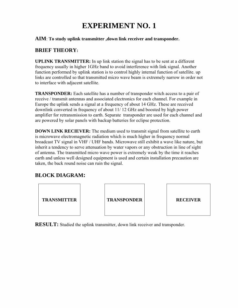
EXPERIMENT NO. 1 AIM: To study uplink transmitter ,down link receiver and transponder. BRIEF THEORY: UPLINK TRANSMITTER: In up link station the signal has to be sent at a different frequency usually in higher 1GHz band to avoid interference with link signal. Another function performed by uplink station is to control highly internal function of satellite. up links are controlled so that transmitted micro wave beam is extremely narrow in order not to interface with adjacent satellite. TRANSPONDER: Each satellite has a number of transponder witch access to a pair of receive / transmit antennas and associated electronics for each channel. For example in Europe the uplink sends a signal at a frequency of about 14 GHz. These are received downlink converted in frequency of about 11/ 12 GHz and boosted by high power amplifier for retransmission to earth. Separate transponder are used for each channel and are powered by solar panels with backup batteries for eclipse protection. DOWN LINK RECIEVER: The medium used to transmit signal from satellite to earth is microwave electromagnetic radiation which is much higher in frequency normal broadcast TV signal in VHF / UHF bands. Microwave still exhibit a wave like nature, but inherit a tendency to serve attenuation by water vapors or any obstruction in line of sight of antenna. The transmitted micro wave power is extremely weak by the time it reaches earth and unless well designed equipment is used and certain installation precaution are taken, the back round noise can ruin the signal. BLOCK DIAGRAM:
TRANSMITTER TRANSPONDER RECEIVER
RESULT: Studied the uplink transmitter, down link receiver and transponder.

QUIZ: Q.1.What is passive satellite? Ans. These satellites simply reflect signal back to earth. Q 2. What is active satellite? Ans. These electronically repeat the signal and send it back to earth. Q .3. What is Non synchronous satellite? Ans. These satellites rotate around the earth in a low altitude elliptical or circular pattern. Q. 4. What is geosynchronous satellite? Ans. These satellite orbits in a circular pattern with an angular velocity equal to that of earth. Q. 5. Explain ITU? Ans. International Telecommunication Union. Q .6. Define Transponder. Ans. A microwave repeater, which receives, amplies, down converts and retransmits signals at a communication satellite. Q .7. Define Uplink. Ans. The earth station electronics and antenna which transmit information to a communication satellite. Q .8 Explain IFRB. Ans. International Frequency Registration Board. Q. 9. What is CCIR? Ans. International Radio Consultative Committee. Q .10 What is CCITT? Ans: International Telegraph and Telephone consultative Committee.

EXPERIMENT NO. 2. AIM:-To establish a direct communication link between Uplink transmitter and Downlink receiver using tone signal. APPARATUS REQUIRED: - Uplink Transmitter, Downlink Receiver, dish antennas and connecting cables. BRIEF THEORY: - To radiate or receive electromagnetic waves an antenna is required. Antenna is system of elevated conductors which couples or matches the transmitter or receiver to free space. A transmitting antenna connecting to a transmitter by transmission line, forces electromagnetic waves in to free space which travel in space with velocity of light. BLOCK DIAGRAM:-
TRANSMITTER
RECEIVER
PROCEDURE:-
1. Connect the satellite uplink transmitter to AC mains. 2. Switch on the transmitter by mains switch and frequency display will come on. 3. The transmitting frequency can be selected by up –down switch. The frequency
can be changed from 1200 -1250-1300 MHz. 4. The transmitter on –off switch will switch on –off the transmission. 5. Connect X1 antenna to uplink transmitter with BNC –BNC cable. 6. Set the o/p gain of uplink transmitter to maximum. 7. Place downlink receiver at a distance of 5-7 m. 8. Connect the downlink receiver to the AC mains and switch it on by mains switch. 9. The downlink receiver frequency can be changed from 1100 -1150 -1200 MHz. 10. The downlink receiver also has tuning potentiometer, which can be used to tune
any frequency from 950- 1500 MHz. 11. Keep the tuning POT fully anticlockwise. 12. The downlink receiver on –off switch will switch on –off the receiver. 13. Attach R2 antenna to the downlink receiver with BNC –BNC cables. 14. Align both the transmitter and receiver antenna in line. 15. Keep the uplink transmitter frequency to 1200 MHz. 16. Keep the downlink receiver frequency to 1200 MHz. 17. Now connect Tone out signal to tone input of the uplink transmitter by patch
cord. 18. Keep downlink receiver voice switch in the on position and you will be able to
hear tone in the speaker of receiver. 19. This is a test link for direct communication between transmitter and receiver.
20. Connect any other audio signal to the Audio2 of uplink transmitter and you will hear the music in the speaker of downlink receiver.
RESULT: - A clear music indicates that the microwave link has been successfully set up between Uplink transmitter and Downlink receiver.
DISCUSSION:-Direct Communication link is established without using satellite as a transponder. PRECAUTIONS: - 1. Connection should be tight. 2. Switch off power supply after performing the experiment. QUIZ:- Q .1. What is X- band used for? Ans. Military purposes Q .2. What is C- band used for? Ans. Commercial purposes Q. 3. Which frequency band is used for commercial comm. Ans. 6/4 GHz band Q. 4. Why 6/4 band is most popular? Ans. Fewest propagation problems. Rain attenuation not sermons. Q.5. What is advantage of satellite communication. Ans. Point –to – multipoint comm. Q. 6. What is EIRP? Ans. Effective Isotropic Radiated Power Q.7. What is figure of merit? Ans. Gr/Ts ratio it decides quality of a earth station. Q.8. What is complete link design? Ans. It is made up of uplink and downlink. Q.9. On which link overall quality depends? Ans. Downlink design. Q.10. What is analog base band signal? Ans. It is the voice signal in the form of voltage generated by a telephone set.
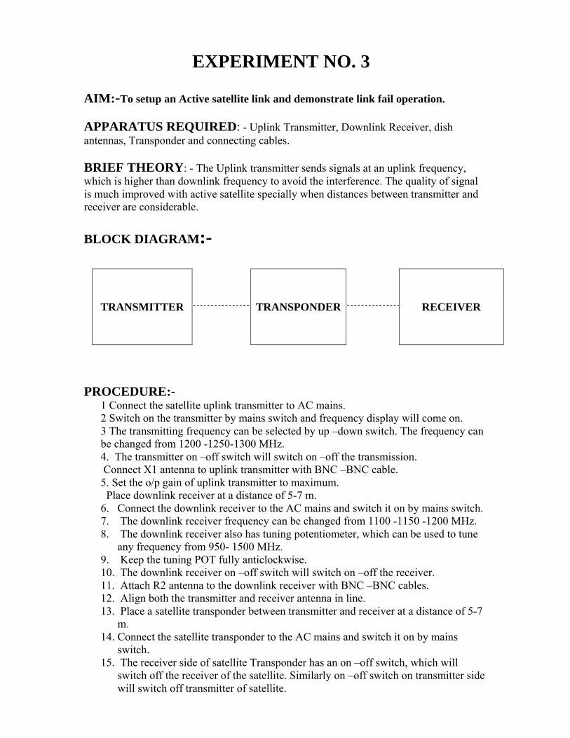
EXPERIMENT NO. 3 AIM:-To setup an Active satellite link and demonstrate link fail operation. APPARATUS REQUIRED: - Uplink Transmitter, Downlink Receiver, dish antennas, Transponder and connecting cables. BRIEF THEORY: - The Uplink transmitter sends signals at an uplink frequency, which is higher than downlink frequency to avoid the interference. The quality of signal is much improved with active satellite specially when distances between transmitter and receiver are considerable.
BLOCK DIAGRAM:-
TRANSMITTER
TRANSPONDER
RECEIVER
PROCEDURE:-
1 Connect the satellite uplink transmitter to AC mains. 2 Switch on the transmitter by mains switch and frequency display will come on. 3 The transmitting frequency can be selected by up –down switch. The frequency can be changed from 1200 -1250-1300 MHz. 4. The transmitter on –off switch will switch on –off the transmission. Connect X1 antenna to uplink transmitter with BNC –BNC cable. 5. Set the o/p gain of uplink transmitter to maximum. Place downlink receiver at a distance of 5-7 m. 6. Connect the downlink receiver to the AC mains and switch it on by mains switch. 7. The downlink receiver frequency can be changed from 1100 -1150 -1200 MHz. 8. The downlink receiver also has tuning potentiometer, which can be used to tune
any frequency from 950- 1500 MHz. 9. Keep the tuning POT fully anticlockwise. 10. The downlink receiver on –off switch will switch on –off the receiver. 11. Attach R2 antenna to the downlink receiver with BNC –BNC cables. 12. Align both the transmitter and receiver antenna in line. 13. Place a satellite transponder between transmitter and receiver at a distance of 5-7
m. 14. Connect the satellite transponder to the AC mains and switch it on by mains
switch. 15. The receiver side of satellite Transponder has an on –off switch, which will
switch off the receiver of the satellite. Similarly on –off switch on transmitter side will switch off transmitter of satellite.

16. Adjust transmitter uplink frequency to 1300 MHz and transponder receiver frequency also to 1300MHz.
17. Keep downlink frequency of Transponder to 1100MHz. 18. Keep the downlink receiver to 1100MHz. 19. Now connect a tone output to tone input of the uplink transmitter by patch cord. 20. Keep downlink receiver voice switch in the on position and you will be able to
hear tone in the speaker of receiver. 21. This is a test link for Active satellite communication. 22. Connect any other audio signal to the Audio 2 of uplink transmitter and you will
hear the music in the speaker of downlink receiver. RESULT: -The above set up shows that a successful satellite communication link has been set up between transmitter and receiver. DISCUSSION:-Hence successful transmission is established using satellite as a transponder. PRECAUTIONS: - 1. Connection should be tight. 2. Switch off power supply after performing the experiment. QUIZ:- Q .1. What is Multiplexing? Ans. Transmission of different signal in a form that these do not interfere with each other is termed multiplexing. Q .2. What is Carson rule? Ans. B=2(Δf +fm) Q. 3. What is SCPC? Ans. Single channel Per Carrier System. Q. 4. Where it is used for? Ans. It is used for earth stations with relatively few channels. Q.5. What are advantage of SCPC? Ans.It does not require expensive multiplexing and demultiplexing, hence cost reduced. Q. 6. What is bit? Ans. It is used for binary digit. Q.7. What is baud? Ans. It is unit of signaling speed. Q.8. What is digital base band signal? Ans. It is combination of logical ones and zero. Q.9. What is orthogonal signal? Ans. If inner product (Sr.Sj) =0 Q.10. What is ASK? Ans. Amplitude Shift Keying.

EXPERIMENT NO.4 AIM:-To establish an AUDIO-VIDEO satellite link between Transmitter and Receiver. APPARATUS REQUIRED: - Uplink Transmitter, Downlink Receiver, dish antennas, Transponder, monitor and connecting cables. BRIEF THEORY: - The Uplink transmitter sends signals at an uplink frequency, which is higher than downlink frequency to avoid the interference. The quality of signal is much improved with active satellite specially when distances between transmitter and receiver are considerable.
BLOCK DIAGRAM:-
VCD PLAYER TRANSMITTER
TRANSPONDER
RECEIVER TV
PROCEDURE:-
1 Connect the satellite uplink transmitter to AC mains. 2 Switch on the transmitter by mains switch and frequency display will come on. 3 The transmitting frequency can be selected by up –down switch. The frequency can be changed from 1200 -1250-1300 MHz. 3 The transmitter on –off switch will switch on –off the transmission. 4 Connect X1 antenna to uplink transmitter with BNC –BNC cable. 5 Set the o/p gain of uplink transmitter to maximum. 6 Place downlink receiver at a distance of 5-7 m. 7 Connect the downlink receiver to the AC mains and switch it on by mains switch. 8 The downlink receiver frequency can be changed from 1100 -1150 -1200 MHz. 9 The downlink receiver also has tuning potentiometer, which can be used to tune
any frequency from 950- 1500 MHz. 10 Keep the tuning POT fully anticlockwise. 11 The downlink receiver on –off switch will switch on –off the receiver. 12 Attach R2 antenna to the downlink receiver with BNC –BNC cables. 13 Align both the transmitter and receiver antenna in line. 14 Place a satellite transponder between transmitter and receiver at a distance of 5-7
m. 15 Connect the satellite transponder to the AC mains and switch it on by mains
switch. 16 The receiver side of satellite Transponder has an on –off switch, which will
switch off the receiver of the satellite. Similarly on –off switch on transmitter side will switch off transmitter of satellite.
17 Adjust transmitter uplink frequency to 1300 MHz and transponder receiver frequency also to 1300MHz.
18 Keep downlink frequency of Transponder to 1100MHz. 19 Keep the downlink receiver to 1100MHz.

20 Connect the Audio/Video signal at the input socket provided on the Uplink Transmitter, Video at video input and audio at audio 1 input.
22. Connect TV monitor to the Audio/Video o/p of downlink receiver. Set TV in AV mode. 23. The TV monitor will display video and audio signal that you have connected to uplink transmitter input.
RESULT: -The monitor display shows that a successful audio and video link has been establish between Transmitter and Receiver through satellite. DISCUSSION: - The quality of signal is much improved with active satellite specially when distances between transmitter and receiver are considerable. PRECAUTIONS: - 1. Connection should be tight. 2. Switch off power supply after performing the experiment. QUIZ:- Q .1. Give another name of ASK. Ans. OOK: - On Off Keying. Q .2. What is PSK? Ans. Phase Shift Keying. Q. 3. What are main problems with comm. satellite reaching the orbit? Ans. Launching and putting the satellite in to geostationary orbit maintaining it. Q. 4. What is apogee? Ans. The point where the satellite is farthest from the earth. Q.5. What is perigee? Ans.The point where satellite is closest from the earth. Q. 6. What are look angle? Ans. The look angles are the angles to which an earth station antenna must be pointed to communicate with the geosynchronous satellite. Q.7. What is trace? Ans. The movement of the electron beam from left to right on a television screen. Q.8. What is threshold? Ans. A minimal signal to noise input required to allow a video receiver to deliver an acceptable picture. Q.9. What is thermal noise? Ans. Random, undesired electrical signals caused by molecular motion, known more familiarly as noise. Q.10. UHF stands for. Ans. Ultraviolet High Frequency.

EXPERIMENT NO.5 AIM:-To communicate VOICE-signal through satellite link. APPARATUS REQUIRED: - Uplink Transmitter, Downlink Receiver, dish antennas, Transponder, mike, and connecting cables. BRIEF THEORY: - The Uplink transmitter sends signals at an uplink frequency, which is higher than downlink frequency to avoid the interference. The quality of signal is much improved with active satellite specially when distances between transmitter and receiver are considerable.
BLOCK DIAGRAM:-
MIC. TRANSMITTER
TRANSPONDER
RECEIVER SPEAKER
PROCEDURE:-
21 Connect the satellite uplink transmitter to AC mains. 22 Switch on the transmitter by mains switch and frequency display will come on. 23 The transmitting frequency can be selected by up –down switch. The frequency
can be changed from 1200 -1250-1300 MHz. 24 The transmitter on –off switch will switch on –off the transmission. 25 Connect X1 antenna to uplink transmitter with BNC –BNC cable. 26 Set the o/p gain of uplink transmitter to maximum. 27 Place downlink receiver at a distance of 5-7 m. 28 Connect the downlink receiver to the AC mains and switch it on by mains switch. 29 The downlink receiver frequency can be changed from 1100 -1150 -1200 MHz. 30 The downlink receiver also has tuning potentiometer, which can be used to tune
any frequency from 950- 1500 MHz. 31 Keep the tuning POT fully anticlockwise. 32 The downlink receiver on –off switch will switch on –off the receiver. 33 Attach R2 antenna to the downlink receiver with BNC –BNC cables. 34 Align both the transmitter and receiver antenna in line. 35 Place a satellite transponder between transmitter and receiver at a distance of 5-7
m. 36 Connect the satellite transponder to the AC mains and switch it on by mains
switch. 37 The receiver side of satellite Transponder has an on –off switch, which will
switch off the receiver of the satellite. Similarly on –off switch on transmitter side will switch off transmitter of satellite.

38 Adjust transmitter uplink frequency to 1300 MHz and transponder receiver frequency also to 1300MHz.
39 Keep downlink frequency of Transponder to 1100MHz. 40 Keep the downlink receiver to 1100MHz. 41 Connect mike i/p at the socket marked MIC on the uplink transmitter. 22. Connect the voice link of uplink transmitter and downlink receiver. 23. Speak in the mike and you will hear the same sound in the speaker of receiver.
RESULT: -The above shows a successful established of voice link between transmitter and receiver. DISCUSSION: - The Uplink transmitter sends signals at an uplink frequency, which is higher than downlink frequency to avoid the interference. PRECAUTIONS: - 1. Connection should be tight. 2. Switch off power supply after performing the experiment. QUIZ:- Q .1. Define VSWR. Ans. The ratio between the minimum and maximum voltage on a transmission line. Q .2. What is the Up converter? Ans. A device that increases the frequency of a transmitted signal. Q. 3. Define Trace. Ans. The movement of the electron beam from left to right on a television screen. Q. 4. What is threshold? Ans. A minimal signal to noise input required to allow a video receiver to deliver an acceptable picture. Q.5. What isVTO (Voltage Tuned Oscillator)? Ans.An electronic circuit whose o/p oscillator frequency is adjusted by voltage. Q. 6. What is Splitter? Ans. A device that takes a signal and splits it in to two to more identical but lower power signals. Q.7. What is Tap? Ans. A device that channels a specific amount of energy out the main distribution system to a secondary outlet. Q.8. PSD stands for. Ans. Polarity Selection Device. Q.9. What is Raster? Ans. The random pattern of illumination seen on a television screen when no video signal is present. Q.10. What is Hum Bars? Ans. A form of interference seen as horizontal bars or black regions passing across the field of a television.

EXPERIMENT NO.6 AIM:-To change different combinations of uplink and downlink frequencies and to check the communication link. APPARATUS REQUIRED: - Uplink Transmitter, Downlink Receiver, dish antennas, Transponder, monitor, and connecting cables. BRIEF THEORY: - The Uplink transmitter sends signals at an uplink frequency, which is higher than downlink frequency to avoid the interference. The quality of signal is much improved with active satellite specially when distances between transmitter and receiver are considerable.
BLOCK DIAGRAM:-
TRANSMITTER
TRANSPONDER
RECEIVER
PROCEDURE:-
1 Connect the satellite uplink transmitter to AC mains. 2 Switch on the transmitter by mains switch and frequency display will come on. 3 The transmitting frequency can be selected by up –down switch. The frequency can be changed from 1200 -1250-1300 MHz. 4 The transmitter on –off switch will switch on –off the transmission. 5 Connect X1 antenna to uplink transmitter with BNC –BNC cable. 6 Set the o/p gain of uplink transmitter to maximum. 7 Place downlink receiver at a distance of 5-7 m. 8 Connect the downlink receiver to the AC mains and switch it on by mains switch. 9 The downlink receiver frequency can be changed from 1100 -1150 -1200 MHz. 10 The downlink receiver also has tuning potentiometer, which can be used to tune
any frequency from 950- 1500 MHz. 11 Keep the tuning POT fully anticlockwise. 12 The downlink receiver on –off switch will switch on –off the receiver. 13 Attach R2 antenna to the downlink receiver with BNC –BNC cables. 14 Align both the transmitter and receiver antenna in line. 15 Place a satellite transponder between transmitter and receiver at a distance of 5-7
m. 16 Connect the satellite transponder to the AC mains and switch it on by mains
switch.
17 The receiver side of satellite Transponder has an on –off switch, which will switch off the receiver of the satellite. Similarly on –off switch on transmitter side will switch off transmitter of satellite.
18 Adjust transmitter uplink frequency to 1300 MHz and transponder receiver frequency also to 1300MHz.
19 Keep downlink frequency of Transponder to 1100MHz. 20 Keep the downlink receiver to 1100MHz. 21 Connect the AUDIO/VIDEO signal at the i/p socket provided on the uplink
transmitter, Video at video input audio at audio 1 input. 22. Connect TV monitor to the Audio/Video o/p of downlink receiver. Set TV in AV mode. 23. The TV monitor will display video and audio signal that you have connected to uplink transmitter i/p. 24. Now change uplink transmitter frequency from 1300 to 1250 MHz and correspondingly the receiver frequency of transponder is to be changed to 1250 MHz. you will receive the same quality of signal at the o/p of the uplink receiver. 25. Now change the downlink frequency of transponder from 1100 to 1150 MHz and similarly change downlink receiver tuning frequency to 1150 MHz. you will be receiving the same quality of signal. Try different combinations of uplink and downlink frequency and also by using tuner of receiver. 26. When the transmitter and receiver both are 1200MHz. you will see the distortion on monitor because both uplink and downlink frequency are same and receiver is receiving two links.
RESULT: The above shows a successful establishment of satellite audio/video link between uplink transmitter and downlink receiver at different uplink and downlink frequencies. DISCUSSION: - When the transmitter and receiver both are 1200MHz, you will see the distortion on monitor. PRECAUTIONS: - 1. Connection should be tight. 2. Switch off power supply after performing the experiment. QUIZ:- Q.1 Define AFC? Ans. A circuit which locks an electronic component in to a chosen frequency. Q.2 Define AGC? Ans. A circuit that uses feedback to maintain the o/p of an electronic component at a constant level. Q.3 What is Back Porch? Ans. That portion of the horizontal blanking pulse that follows the trailing edge of the horizontal sync pulse. Q.4 What is Bird? Ans. Jargon or nickname for communication satellite. Q.5 What is blanking pulse level?

Ans. The reference level for video signal. The blanking pulses must be aligned at the i/p to the picture tube. Q.6 What is blanking signal? Ans. Pulses used to extinguish the scan illumination during horizontal and vertical retrace periods. Q.7 What is board band? Ans. A device that processes a signal spanning a relatively board range of input frequencies. Q.8 What is clamp circuit? Ans. A circuit that removes the dispersion waveform from the downlink signal. Q.9 What is Conus? Ans. An abbreviation for the continental United States. Q. 10 What is Composite Video Signal? Ans. The complete video signal consisting of the chrominance and luminance information as well as all sync and blanking pulses.

EXPERIMENT NO.7 AIM: - To transmit and receive three separate signals (Audio, Video, Tone) simultaneously through satellite link. APPARATUS REQUIRED: - Uplink Transmitter, Downlink Receiver, dish antennas, Transponder, VCD Player, Monitor and connecting cables. BRIEF THEORY: - The Uplink transmitter sends signals at an uplink frequency, which is higher than downlink frequency to avoid the interference. The quality of signal is much improved with active satellite specially when distances between transmitter and receiver are considerable.
BLOCK DIAGRAM:-
VCD PLAYER TRANSMITTER
TRANSPONDER
RECEIVER MONITOR
PROCEDURE:-
1 Connect the satellite uplink transmitter to AC mains. 2 Switch on the transmitter by mains switch and frequency display will come on. 3 The transmitting frequency can be selected by up –down switch. The frequency can be changed from 1200 -1250-1300 MHz. 4 The transmitter on –off switch will switch on –off the transmission. 5 Connect X1 antenna to uplink transmitter with BNC –BNC cable. 6 Set the o/p gain of uplink transmitter to maximum. 7 Place downlink receiver at a distance of 5-7 m. 8 Connect the downlink receiver to the AC mains and switch it on by mains switch. 9 The downlink receiver frequency can be changed from 1100 -1150 -1200 MHz. 10 The downlink receiver also has tuning potentiometer, which can be used to tune any frequency from 950- 1500 MHz. 11 Keep the tuning POT fully anticlockwise. 12 The downlink receiver on –off switch will switch on –off the receiver. 13 Attach R2 antenna to the downlink receiver with BNC –BNC cables. 14 Align both the transmitter and receiver antenna in line. 15 Place a satellite transponder between transmitter and receiver at a distance of 5-7 m.

16 Connect the satellite transponder to the AC mains and switch it on by mains switch. 17 The receiver side of satellite Transponder has an on –off switch, which will
switch off the receiver of the satellite. Similarly on –off switch on transmitter side will switch off transmitter of satellite.
18 Adjust transmitter uplink frequency to 1300 MHz and transponder receiver frequency also to 1300MHz.
19 Keep downlink frequency of Transponder to 1100MHz. 20 Keep the downlink receiver to 1100MHz. 21 Connect the AUDIO/VIDEO signal at the i/p socket provided on the uplink
transmitter, Video at video input audio at audio 1 input. And connect tone out signal to Audio 2 input of the uplink transmitter by patch cord.
22. Connect TV monitor to the Audio/Video o/p of downlink receiver. Set TV in AV mode. Keep downlink receiver voice switch in the on position. 23. The TV monitor will display video and audio signal that you have connected to uplink transmitter i/p.and you will be able to hear tone in the speaker of receiver.
RESULT: Three separate signals (Audio, Video, Tone) are successfully received at downlink receiver through satellite communication link. DISCUSSION: - Three separate signals can be successfully transmitted using satellite comm. link. PRECAUTIONS: - 1. Connection should be tight. 2. Switch off power supply after performing the experiment. QUIZ:- Q.1 What is cross modulation? Ans. A form of interference caused by the modulation of one carrier affecting that of another signal. Q.2 What is Dc power Block? Ans. A device which stops the flow of dc power but permits passage of higher frequency ac signals. Q.3 What is Detent Tuning? Ans. Tuning in to a satellite channel by selecting a preset resistance. Q.4 What is Domsat? Ans. Abbreviation for domestic communication Satellite. Q.5 What is Drifting? Ans. An instability in a preset voltage, frequency or other electronic circuit parameter. Q.6 What is Elevation Angle? Ans. The vertical angle measured from the horizontal up to a targeted Satellite. Q.7 Define F/D Ratio? Ans. The ratio of an antenna's focal length to diameter. It describes antenna “depth ˝. Q.8 What is Inclinometer? Ans. An instrument used to measure the angle of elevation to a satellite from the surface of the earth. Q.9 What is Insertion Loss?

Ans. The amount of signal energy lost when a device is inserted in to a communication line. Also known as feed – through loss. Q. 10 Define INTELSAT? Ans. The International Telecommunication Satellite Consortium, a body of 154 countries working towards a common goal of improved worldwide satellite communications.

EXPERIMENT NO.8 AIM: - To transmit and receive function generator waveforms through satellite link. APPARATUS REQUIRED: - Uplink Transmitter, Downlink Receiver, dish antennas, Transponder, function generator,CRO and connecting cables. BRIEF THEORY: - The Uplink transmitter sends signals at an uplink frequency, which is higher than downlink frequency to avoid the interference. The quality of signal is much improved with active satellite specially when distances between transmitter and receiver are considerable.
BLOCK DIAGRAM:-
FUNCTION GENERATOR TRANSMITTER
TRANSPONDER
RECEIVER CRO
PROCEDURE:-
1 Connect the satellite uplink transmitter to AC mains. 2 Switch on the transmitter by mains switch and frequency display will come on. 3 The transmitting frequency can be selected by up –down switch. The frequency
can be changed from 1200 -1250-1300 MHz. 4 The transmitter on –off switch will switch on –off the transmission. 5 Connect X1 antenna to uplink transmitter with BNC –BNC cable. 6 Set the o/p gain of uplink transmitter to maximum. 7 Place downlink receiver at a distance of 5-7 m. 8 Connect the downlink receiver to the AC mains and switch it on by mains switch. 9 The downlink receiver frequency can be changed from 1100 -1150 -1200 MHz. 10 The downlink receiver also has tuning potentiometer, which can be used to tune
any frequency from 950- 1500 MHz. 11 Keep the tuning POT fully anticlockwise. 12 The downlink receiver on –off switch will switch on –off the receiver. 13 Attach R2 antenna to the downlink receiver with BNC –BNC cables. 14 Align both the transmitter and receiver antenna in line. 15 Place a satellite transponder between transmitter and receiver at a distance of 5-7
m. 16 Connect the satellite transponder to the AC mains and switch it on by mains
switch. 17 The receiver side of satellite Transponder has an on –off switch, which will
switch off the receiver of the satellite. Similarly on –off switch on transmitter side will switch off transmitter of satellite.
18 Adjust transmitter uplink frequency to 1300 MHz and transponder receiver frequency also to 1300MHz.
19 Keep downlink frequency of Transponder to 1100MHz. 20 Keep the downlink receiver to 1100MHz. 21 Connect function generator sine wave output to DATA input terminals provided
on uplink transmitter. 22. Connect data o/p of downlink receiver to the oscilloscope. 23. Feed the signal of 1KHz Sine wave and you will observe similar sine wave of same frequency on Oscilloscope. 24. Change Sine to Square, Triangular, etc and you will observe the same wave shape on CRO.
RESULT: Function generator waveforms are successfully received at downlink receiver through satellite communication link. DISCUSSION:- Function generator waveforms are successfully transmitted at uplink transmitter through satellite communication link. PRECAUTIONS: - 1. Connection should be tight. 2. Switch off power supply after performing the experiment. QUIZ:- Q.1What is PAL? Ans. Phase Alternate Line. The European color TV format which evolved from the American NTSC standard. Q.2 What is Pad? Ans. A concrete base upon which a supporting pole and antenna can be mounted. Q.3 What is Q Signal? Ans. One of two color video signal components used to modulate the color sub carrier. It represents the color range from yellow to green to magenta. Q.4 What is Raster? Ans. The random pattern of illumination seen on a television screen when no video signal is present. Q.5 What is SAW (Surface Acoustic Wave) filter? Ans. A solid state filter that yields a sharp transition between regions of transmitted and attenuated frequencies. Q.6 What is Reference signal? Ans. A highly stable signal used as a standard againsted which other variable signals may be compared and adjusted. Q.7 What is Vertical Blanking Pulse? Ans. A pulse used during the vertical retrace period at the end of each scanning field to extinguish illumination from the electron beam. Q. 8 What is the difference between TV transmission center and Satellite transmission center. Ans. TV transmitter transmits its signals in VHF/UHF range and Satellite transmitter uses SHF range. Q.10 What is the function of LNB? Ans. LNB is mounted on dish antenna so as to minimize the transmission losses, the these signals are sent to satellite receiver.

EXPERIMENT NO.9 AIM: - To transmit and receive PC data through satellite link. APPARATUS REQUIRED: - Uplink Transmitter, Downlink Receiver, dish antennas, Transponder, 2 No. of RS-232 9-pin cables ,2 Male to -1 Female RS -232 cable,2 sets of PC ,Satellite software and connecting cables. BRIEF THEORY: - The Uplink transmitter sends signals at an uplink frequency, which is higher than downlink frequency to avoid the interference. The quality of signal is much improved with active satellite specially when distances between transmitter and receiver are considerable.
BLOCK DIAGRAM:-
P. C. TRANSMITTER
TRANSPONDER
RECEIVER P. C.
PROCEDURE:-
1Connect the satellite uplink transmitter to AC mains. 2 Switch on the transmitter by mains switch and frequency display will come on. 3 The transmitting frequency can be selected by up –down switch. The frequency
can be changed from 1200 -1250-1300 MHz. 4 The transmitter on –off switch will switch on –off the transmission. 5 Connect X1 antenna to uplink transmitter with BNC –BNC cable. 6 Set the o/p gain of uplink transmitter to maximum. 7 Place downlink receiver at a distance of 5-7 m. 8 Connect the downlink receiver to the AC mains and switch it on by mains switch. 9 The downlink receiver frequency can be changed from 1100 -1150 -1200 MHz. 10 The downlink receiver also has tuning potentiometer, which can be used to tune
any frequency from 950- 1500 MHz. 11 Keep the tuning POT fully anticlockwise. 12 The downlink receiver on –off switch will switch on –off the receiver. 13 Attach R2 antenna to the downlink receiver with BNC –BNC cables. 14 Align both the transmitter and receiver antenna in line. 15 Place a satellite transponder between transmitter and receiver at a distance of 5-7
m. 16 Connect the satellite transponder to the AC mains and switch it on by mains
switch. 17 The receiver side of satellite Transponder has an on –off switch, which will
switch off the receiver of the satellite. Similarly on –off switch on transmitter side will switch off transmitter of satellite.
18 Adjust transmitter uplink frequency to 1300 MHz and transponder receiver frequency also to 1300MHz.
19 Keep downlink frequency of Transponder to 1100MHz. 20 Keep the downlink receiver to 1100MHz.

21 Connect RS -232 cable from uplink transmitter to one set of PC. 22. Connect RS -232 cable from downlink receiver to one set of PC. 23. Switch on the PC and install sat. Software on both PC and select communication port COM 1 on both PC. 24. When the link is established, the typed matter on first set up PC will be transmitted to second set up PC via. Satellite link. (If transmitted data is not received correctly then adjust gain POT of satellite transponder.)
RESULT: PC data transmitted from first setup PC is received in the second setup PC via. Satellite link. DISCUSSION:- PRECAUTION: - 1. Connection should be tight. 2. Switch off power supply after performing the experiment. QUIZ:- Q.1 What is the Reed Switch? Ans. A mechanical switch which uses two thin silver of metal in a glass tube to make and break electrical contact. Q.2 What is the range of UHF and SHF bands. Ans. UHF band range is 300-3000 MHz and SHF band range is 3000-30000 MHz. Q.3 Define S/N Ratio? Ans. The ratio of signal power to noise power in a specified bandwidth, usually expressed in decibels. Q.4 VSAT stands for. Ans. Very Small Aperture Terminal Q.5 What is the land application of MSAT? Ans. Constructing projects in remote areas. Q.6 What is bore sight? Ans. The direction along the principle axis of either a transmitting or a receiving antenna. Q.7 What is the Isolator? Ans. A device that allows signals to pass unobstructed in one direction but which attenuates their strength in the reverse direction. Q.8 What is Inclinometer? Ans. An instrument used to measure the angle of elevation to a satellite from the surface of the earth. Q. 9 What is Longitude? Ans. The distance in degrees east or west of the prime meridian, located at zero degrees. Q.10 What is Servo Hunting? Ans. An oscillatory searching of the feed horn probe when use of inadequate gauge control cables results in insufficient voltage at the feed horn
TRAFFIC BURST 1
RB2 TRAFFIC BURST N
TDMA FRAME
EXPERIMENT NO: - 10
AIM: - To study TDMA and TDMA frame structure. BRIEF THEORY:-
TDMA:-In TDMA, many earth stations in the satellite communication network use a single carrier for transmission via satellite transponder on a time- division basis these earth station transmit traffic bursts in a periodic time frame which is termed TDMA frame.
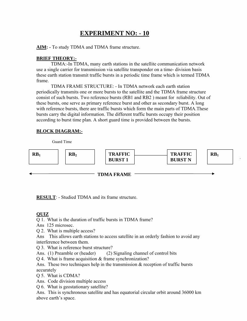
TDMA FRAME STRUCTURE: - In TDMA network each earth station periodically transmits one or more bursts to the satellite and the TDMA frame structure consist of such bursts. Two reference bursts (RB1 and RB2 ) meant for reliability. Out of these bursts, one serve as primary reference burst and other as secondary burst. A long with reference bursts, there are traffic bursts which form the main parts of TDMA.These bursts carry the digital information. The different traffic bursts occupy their position according to burst time plan. A short guard time is provided between the bursts.
BLOCK DIAGRAM:- Guard Time
RESULT: - Studied TDMA and its frame structure. QUIZ Q 1. What is the duration of traffic bursts in TDMA frame? Ans 125 microsec. Q 2. What is multiple access? Ans This allows earth stations to access satellite in an orderly fashion to avoid any interference between them. Q 3. What is reference burst structure? Ans. (1) Preamble or (header) (2) Signaling channel of control bits Q 4. What is frame acquisition & frame synchronization? Ans. These two techniques help in the transmission & reception of traffic bursts accurately Q 5. What is CDMA? Ans. Code division multiple access Q 6. What is geostationary satellite? Ans. This is synchronous satellite and has equatorial circular orbit around 36000 km above earth’s space.
RB1 RB1
Q 7. What are look angles? Ans. (1) Azimuth angle (A) (2) Elevation angle (E) Q 8. What are repeaters? Ans. These provide the receiver & transmit coverage for the satellite. Q 9 What is packet? Ans. A packet of information is a finite sequence of bits. Q 10. What is kepler’s first law? Ans. According to Kepler’s law,satellite move along a orbit on the orbit plane.