satelline 2asx sw 4.4 user guide - induo ab · pdf filethey only difference is in the design...
TRANSCRIPT

TABLE OF CONTENTS Page
1 SATELLINE-2ASx Radio Data Modem1.1 Radio data modem 31.2 RS-232 pin connections 41.3 Technical specifications 5
2 Transmission with the Radio Modem2.1 Transmission 62.2 Reception 7
2.2.1 RSSI signal 82.3Delays during data transmission 8
3 Asynchronous Data Transmission and Data Speed3.1 Asynchronous character 93.2 Data speed 9
4 Relay Station Using One Radio Modem 10
5 Using of Address in Data Communication5.1 General 105.2 The connection between two points 125.3 A system with one base station and several sub-stations 125.4 A system with one relay station 13
5.4.1 The alternating address of a pair of radio modems 135.5 A system with several relay stations 14
6 Programming of the Radio Modem 6.1 General 15 6.2 Programming mode 15 6.2.1 Programming of address 16 6.2.2 Programming of operating mode 17
6.2.3 Programming of channel 18 6.3 Command program mode 18 6.3.1 Programming of address 18
6.3.2 Programming of channel 19
7 Forming of the SL Command7.1Forming of the programming packet of the address 207.2 Forming of the programming packet of the channel 21
8 Multi Modem Data Systems 8.1 Required sequence of data characters 21
SATELLINE-2ASx
1

8.2 Polling 228.3 Multi Master 22
9 Planning a Radio Modem Network 9.1 Factors affecting quality and distance of
the radio connection 229.2 Radio field strength 23
10 Installation 10.1 RS-232 Interface 2510.2 Supply of current 2610.3 Mounting the antenna 27
11 Equipment11.1 The connection of antennas to radio modems 29
11.1.1 Hand portable equipment 2911.1.2 Equipment installed in vehicles 2911.1.3 Base station 30
11.2 Cables 3011.2.1 RF cables 3011.2.2 Interface cables 30
12 Check List 31
Appendices1. Character Map2A. Delays and reaction time of the RS-232 interface with a
data speed of 9600 bps2B. Delays and reaction time of the RS-232 interface with a
data speed of 9600 bps and immediate response3. Table of selectable channels
**** Due to a continuous product development SATEL OY reserves the right tochange specifications without notice ****
SATELLINE-2ASx
2

1 SATELLINE-2ASx radio data modemThe information in this user guide concerns both SATELLINE-2ASx and SATELLINE-2ASxm2models. In this user guide we call both models SATELLINE-2ASx. The two models areelectrically identical. They only difference is in the design of the housing.
1.1 Radio data modem
The SATELLINE-2ASx radio data modem consists of a 450 MHz:n transmitter, a receiver, asynthesizer and a modem board, housed in a compact weather resistant aluminium casing.The modem has an RS-232 interface which provides the flexibility to connect it to a widevariety of data networks and terminal equipment.
The SATELLINE-2ASx operates similar to a cable although data transmission is half duplex.When planning a radio data modem installation it is important to take into account turnaround delays in the radio modems and possible radio interferences. The most importantRS-232 signals for operation of the radio data modem are indicated by LEDs.
Typical applications of the SATELLINE-2ASx are:
v Replacing an RS-232-cable in situations where installation of a cable is difficult,expensive or even impossible
v Data transmission to and from mobile or portable terminals v Wireless alarm transmissionv Telemetry v Remote controlv Transferring text to displaysv For use with Global Positioning System (GPS)v etc.
With two SATELLINE-2ASx radio data modems it is easy to make up point to pointconnections. The power level of the transmitter is 0,5 W. It is possible to reach distancesfrom 2 to 30 km depending on topographical conditions and antenna locations. Onspecial request it is possible to manfacture transmitters with the maximum output power of1,0 W. Country specific laws of radio communication must always be followed.
The radio data modem operates well in data networks where the same channel is used byseveral mobile terminals. In such systems the protocol can be either polling mode, in whichthe data communication is controlled through one of the radio modems or multimastermode, in which any one of the radio modems can initiate data transmission when theradio channel is free.
SATELLINE-2ASx
3

Due to the incorporation of unique synthesizing techniques the SATELLINE-2ASx is alsosuitable for systems with several base stations using different channels. The mobile substations can easily change frequency for communication with the different base stations.By using this method the coverage area of the system can be enlarged without incurringextra delays due to the capacity of the radio channels.
The handshaking procedure of the SATELLINE-2ASx interface is PC compatible. Mosttelecommunications programs can be used with the modem in order to transmit data.Thisfeature together with the possibility of programming of the radio data modem via theinterface (see paragraph 6) make SATELLINE-2ASx a product with many applicationpossibilities in wireless data communications.
1.2 RS-232 pin connections
Operating voltage positive poleVoltage -VB15Operating voltage positive poleVoltage-VB14Request to SendRS-232INRTS13Mode Selection open/gndINMODE 12Transmit DataRS-232INTD11Data Set Ready RS-232OUTDSR10Receive Data RS-232OUTRD9Operating voltage negative poleGround-GND8Operating voltage negative poleGround-GND7Clear to send RS-232OUTCTS6Receiving signal strength indicator s. NOTEOUTRSSI5
-4-3
Carrier DetectRS-232OUTCD2Data Terminal ReadyRS-232INDTR1
Operation LevelSD *) Line D-connector Pin
*) SD = Signal direction from the radio data modem , IN = Input and OUT = Output
Operation description of the lines pin by pin:
v DTR operates as an ON/OFF switch of the modem v CD indicates a signal on the radio channel exceeding the level of sensitivity of
the modem (it can record radio interferece signal)v RSSI measures the received signal strength of the field of the transmitting radio
(starts approximately from 1 V and goes up to 5 V ). The strength of the fieldincreases with the voltage.
SATELLINE-2ASx
4
v CTS indicates when the radio data modem is clear to receive data via theRS-interface
v GND is the negative pole of the operating voltage and the signal referenceground
v RD output of received data v DSR indicates "ON" state of the modem :v TD input of transmitted data v MODE selection: when line 12 is open, radio data modem is in DATAMODE
and ready for receiving and transmitting data. When the line is connected toground, radio data modem is turned into PROGRAM MODE
v RTS prevents the transfer of data received by the radio modem to the RD-line(see 2.2 and 6.2.2)
v VB positive pole of the operating voltage
1.3 Technical specifications
Satelline-2ASx complies with the following international standards: I-ETS 300 220, CEPT T/R 20-04 and label (m2)
TRANSCEIVERFrequency Range 400...470 MHz / base band 2 MHzChannel Spacing 25 kHzNumber of Channels 16 (selectable by software via RS-232 interface)Frequency Stability < ± 1.5 kHzMethod of modulation FSK
TransmitterCarrier Power 500 mW/ 50 ohm ( + 27 dBm)Adjustment range 20mW... 1 W / 50 ohm (factory set)Carrier Power Stability + 2 dB / - 3 dBFrequency Deviation ± 2.5 kHzAdjacent Channel Power < 200 nWSpurious Radiations I-ETS 300 220
ReceiverSensitivity < -108 dBm (BER < 10 E-4)Co-channel rejection > - 8 dBAdjacent channel selectivity > 65 dBIntermodulation attenuation > 65 dBSpurious radiations < 2 nW
SATELLINE-2ASx
5

DATA MODEM Interface RS-232 Interface Connector D 15 connector, femaleData speed 1200 - 9600 bit/sModulating Signal NRZData formats Asynchronous data
character length:10 or 11 bits
GENERALOperating voltage + 10 ...+ 14 VdcCurrent consumption When DTR is "0": 3 mA
When DTR is "1": Receiving: 120 mATransmitting:600 mA
Antenna Connector TNC, 50 ohm, femaleSize H x W x D 137 x 67 x 29 mm (m2)Installation plate 130 x 63 x 1 mm (m2)Weight 250 g (m2)Temperature range -25 °C...+55 °C
Labelling information:
Ser.no. 96052938 Freq. Ch F 468.200 MHzSATEL OY
Tel: +358-2-777 7800, Fax: +358-2-777 7810
v Serial number v Frequency, preset at the factory. F= setting in programming mode.
468.200 MHz is the corresponding frequency.v Contact information of manufacturer
2 Transmission with the Radio Modem
2.1 Transmission
The Satelline-2ASx is ready to transmit data within 400 ms after the supply voltage isswitched on and the DTR line is in the "ON" state.
There are two different methods of initiating data transmission:1. Transmission based on CTS or CD handshaking2. Data connected directly to the TD line
1. Transmission based on CTS or CD handshaking is implemented, when the user needs to ensure that the radio channel is free and the modem is ready for transmitting data:
v CTS line does not turn "ON" if the radio channel is occupied or if the modem isfor any reason unprepared for transmission
SATELLINE-2ASx
6
v CD line turns "ON" if the radio channel is occupied (i.e. another transmission or a powerful interference is being effected on the same channel)
*****************************************************************************************NOTE !
CTS does not automatically follow the CD line. CTS line is controlled by an receivingsignal in the intern programming of the radio data modem (= programmabledata squelch). Only real received data turns the CTS "OFF". This feature enables datatransmission also in interfering circumstances.
*****************************************************************************************
2. Transmission connected directly to the TD line can be used when:
v The required channel is completely free from other transmissions or overlappingtransmissions are prevented
v The interval between data messages is sufficient (exceeds 60 ms with dataspeed of 9600 bit/s). This is required to empty the data buffer of charactersfrom the previous transmission
v The delay between Rx/Tx is taken into account by switching from receiving totransmission (after receiving the last character a delay exceeding 10 ms beforetransmitting the first character when data speed is 9600 bit/s, not valid if theradio modem is in the state of immediate response (see 6.2.2)
v Data packets are short (less than 100 bytes)v In transmitting long data packets (more than 100 bytes) the terminal should be
set in a state using two (2) stop bits and the radio modem in a state where thetotal number bits of the character is one less than in the terminal. (Prevents thefilling up of the buffer).
If the connection between the radio data modems breaks in the middle of the transmissioni.e. as a result of a weak field, the radio modems can be reconnected by breaking thetransmission and starting a new one.
2.2 Reception
The Satelline-2ASx is ready to receive data within 400 ms after the supply voltage isswitched on and the DTR line is in the "ON" state.
Equipment connected to the radio data modem receives information of incoming data bydetecting changes in the state of the RD line. Start of reception can also be detected fromthe CTS and CD lines. (See 2.1)
In case of interference or external equipment effecting the functions of the radio modem itcan be necessary to prevent the radio modem from receiving. In simplex data transmissionreception can be switched off in the transmitting part of the system. This prevents thepossible external interferences preventing the transmission. (See 6.2.2)
SATELLINE-2ASx
7
In systems with several radio modems the reception of data can be stopped with the RTSline, by setting the "RTS line active" bit as "1" in the programming mode. (Compare with6.2.2) When the RTS line is non active the reception of data from the RD line is interrupted.In this state the radio modem waits for new messages and the changing into transmission isunsuccesful.
2.2.1 RSSI signal
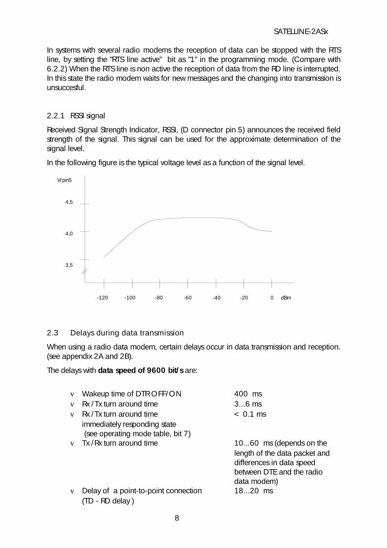
Received Signal Strength Indicator, RSSI, (D connector pin 5) announces the received fieldstrength of the signal. This signal can be used for the approximate determination of thesignal level.
In the following figure is the typical voltage level as a function of the signal level.
V/pin5
4,5
4,0
3,5
-120 -100 -80 -60 -40 -20 0 dBm
2.3 Delays during data transmission
When using a radio data modem, certain delays occur in data transmission and reception.(see appendix 2A and 2B).
The delays with data speed of 9600 bit/s are:
v Wakeup time of DTR OFF/ON 400 msv Rx /Tx turn around time 3...6 msv Rx /Tx turn around time < 0.1 ms
immediately responding state (see operating mode table, bit 7)
v Tx /Rx turn around time 10...60 ms (depends on the length of the data packet and differences in data speed between DTE and the radio data modem)
v Delay of a point-to-point connection 18...20 ms (TD - RD delay )
SATELLINE-2ASx
8
It is possible to use the radio modem in a state , where the Rx/Tx turnaround delay is closeto 0. This state can be activated by programming the "immediate response" bit to position"on".
NOTE
Turn around delays and connection delays double (approx.) by halving thedata speed. (The wake-up time is unchanged)
3 Asynchronous Data Transmission and Data Speed
3.1 Asynchronous character
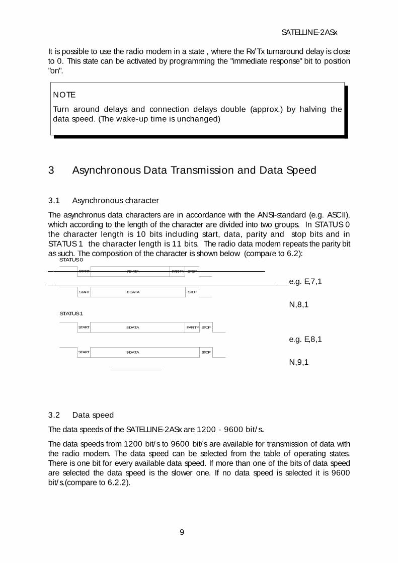
The asynchronus data characters are in accordance with the ANSI-standard (e.g. ASCII),which according to the length of the character are divided into two groups. In STATUS 0the character length is 10 bits including start, data, parity and stop bits and inSTATUS 1 the character length is 11 bits. The radio data modem repeats the parity bitas such. The composition of the character is shown below (compare to 6.2):
e.g. E,7,1
N,8,1
e.g. E,8,1
N,9,1
3.2 Data speed
The data speeds of the SATELLINE-2ASx are 1200 - 9600 bit/s.
The data speeds from 1200 bit/s to 9600 bit/s are available for transmission of data withthe radio modem. The data speed can be selected from the table of operating states.There is one bit for every available data speed. If more than one of the bits of data speedare selected the data speed is the slower one. If no data speed is selected it is 9600bit/s.(compare to 6.2.2).
SATELLINE-2ASx
9
STATUS 0
START 7 DATA PARITY STOP
START 8 DATA STOP
STATUS 1
START 8 DATA STOPPARITY
START 9 DATA STOP

If the character length is incorrectly set, errors will appear in transmission. At reception theyappear as "error characters" or as an incorrect operation of the modem
If the data transmission is in conflict with the selected form there will be errors intransmission. These errors will appear as false characters or inaccurate operation.
4 Relay Station Using One Radio Modem
Short data packets of maximum 106 bytes (SW version 5.06 135 bytes) can be relayedusing one radio modem. The relay feature has to be set on in the programming mode. Inthe relay state the radio modem works as an independent unit. When a radio modem isused only as a relay station it requires a power supply and an antenna. No otherequipment is needed.
A radio modem working as a relay station can also be used for transmission andreception of data. In the relay state the radio modem receives data in the same way asusual. However at the same time it memorizes the received data. After finishing thereception of data the radio modem does not turn back to the state where it observes theinterface lines. It transmits directly the received and memorized data on the same channeland with the same settings as received. At transmission of data from the RS-line thefunctions of the radio modem do not differ from a normal radio modem.
There can be several relay stations in the same system and under the same base station.The relay stations can also be grouped in a chain, wherein the message goes via severalrelay stations. It is necessary to use addresses of the radio modem in a system with severalrelay stations.
5 Using of Address in Data Communication
5.1 General
It is possible to use addresses in both transmitting Tx and receiving Rx. The address consistsof two data characters (altogether 16 bits). The addresses can either be the same in bothdirections or when needed the transmitting and the receiving addresses can be different.
The addresses can be selected separately in both directions. It is also possible to transferthe received address to the RS interface.
SATELLINE-2ASx
10

Transmission
2ASx
Address Data
Data
2ASx
Data
Data
Fig 2 Address of transmission has been set OFF.Radio modem will transmit data packet without the address.
Fig 1 Address of transmission has been set ON.Radio modem will add the address to thebeginning of data packet.
Reception
2ASx
Address Data
Data
2ASx
Address Data
Fig 4 Address of reception has been set ON, butthe address of radio modem is different from theaddress of the received data message. Radiomodem will prevent data packet from beingtransferred to RS-232 interface.
Fig 3 Address of reception has been set ON, andaddress of radio modem is identical to address ofreceived data message. Radio modem will remove the address from thebeginning of data packet and will send data toRS-232 interface. But if the 6th bit of Group II (programming mode)is on, radio modem will send also the address tointerface.
SATELLINE-2ASx
11
2ASx
Data
Data
2ASx
Data
2ASx
Address Data
Address Data
ERROR
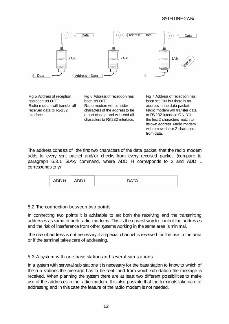
Fig 7 Address of reception hasbeen set ON but there is noaddress in the data packet. Radio modem will transfer data to RS-232 interface ONLY if the first 2 characters match to its own address. Radio modem will remove those 2 charactersfrom data.
Fig 6 Address of reception hasbeen set OFF. Radio modem will considercharacters of the address to bea part of data and will send allcharacters to RS-232 interface.
Fig 5 Address of receptionhas been set OFF. Radio modem will transfer allreceived data to RS-232interface.
The address consists of the first two characters of the data packet, that the radio modemadds to every sent packet and/or checks from every received packet. (compare toparagraph 6.3.1 SLAxy command, where ADD H corresponds to x and ADD Lcorresponds to y)
ADD H ADD L DATA
5.2 The connection between two points
In connecting two points it is advisable to set both the receiving and the transmittingaddresses as same in both radio modems. This is the easiest way to control the addressesand the risk of interference from other systems working in the same area is minimal.
The use of address is not necessary if a special channel is reserved for the use in the areaor if the terminal takes care of addressing.
5.3 A system with one base station and several sub stations
In a system with serveral sub stations it is necessary for the base station to know to which ofthe sub stations the message has to be sent and from which sub-station the message isreceived. When planning the system there are at least two different possibilities to makeuse of the addresses in the radio modem. It is also possible that the terminals take care ofaddressing and in this case the feature of the radio modem is not needed.
SATELLINE-2ASx
12
The address of the base station can always be changed when transmitting from onesub-station to another. In this case the base station can only listen to one sub-station at atime. In a polling system it is possible to use this arrangement because the radio modemscommunicate with each other in pairs.
In a system with Carrier Sense Multiple Access (CSMA) it is not possible to use theaddresses at the base station as the addresses would prevent the base station to hear allthe sub stations. It is useful to change the address of the base station according to thesub-station in a polling system. It is the terminal of the base station that should take care ofthe addition of addresses and checking of data packets.
In these applications the radio modem at the base station is left without an address and theradio modems at the sub stations are set with both the transmitting and the receivingaddress. The software of the base station must be able to treat the addresses given by thebase station and to add to the data packet the addresses of the sub stations.
5.4 A system with one relay station
In systems with several relay, sub and base stations it is necessary to use addresses in theradio modems specially if there are more than one relay station. A system with only onerelay station can be built without using the addresses. However the message will beduplicated on the communication route (the base station hears the messages from both thesub-station and the relay station).
There are at least two alternative ways to use the addresses depending on theprogrammability of the equipment and the number of relay stations and their position toeach other.
5.4.1 The alternating address of a pair of radio modems
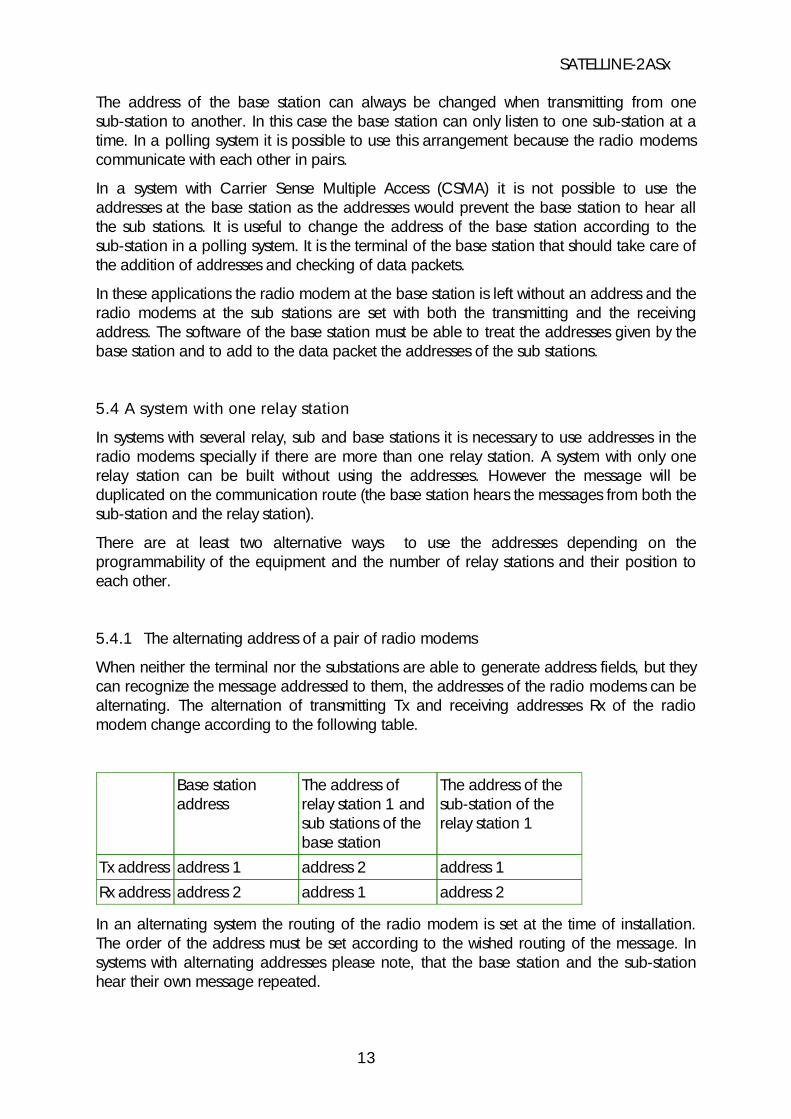
When neither the terminal nor the substations are able to generate address fields, but theycan recognize the message addressed to them, the addresses of the radio modems can bealternating. The alternation of transmitting Tx and receiving addresses Rx of the radiomodem change according to the following table.
address 2address 1address 2Rx addressaddress 1address 2address 1Tx address
The address of thesub-station of therelay station 1
The address ofrelay station 1 andsub stations of thebase station
Base stationaddress
In an alternating system the routing of the radio modem is set at the time of installation.The order of the address must be set according to the wished routing of the message. Insystems with alternating addresses please note, that the base station and the sub-stationhear their own message repeated.
SATELLINE-2ASx
13

5.5 A system with several relay stations
f1 f1
PWRPWR
f1
BASE STATIONSUB STATION
R1 R2
In systems with several adjacent or parallel relay stations addresses should be used. Thisprohibits moving around of the message and secures that only the determined radiomodem receives the message.
The base station and sub-station terminals create a chain of addresses. The address isused in the following way in routing the message:
DATAS ADDR2 ADDR1 ADD
- the message from the radio modem at the base station to the terminal that contains the addresses of the relay stations and the sub-station (R1 ADD is the address of the unit consisting of 2 characters)
DATAS ADDR2 ADD
- the message from the relay station 1 to relay station 2 (goes automatically only if the receiving address is programmed )
DATAS ADD
- the message from the relay station 2 to sub-station 4 (goes automatically if only the receiving address is programmed )
SATELLINE-2ASx
14
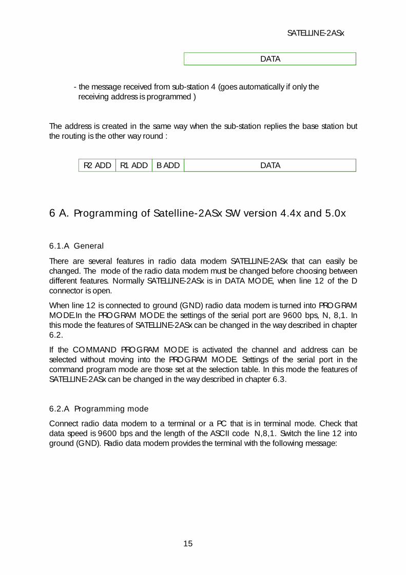
DATA
- the message received from sub-station 4 (goes automatically if only the receiving address is programmed )
The address is created in the same way when the sub-station replies the base station butthe routing is the other way round :
DATAB ADDR1 ADDR2 ADD
6 A. Programming of Satelline-2ASx SW version 4.4x and 5.0x
6.1.A General
There are several features in radio data modem SATELLINE-2ASx that can easily bechanged. The mode of the radio data modem must be changed before choosing betweendifferent features. Normally SATELLINE-2ASx is in DATA MODE, when line 12 of the Dconnector is open.
When line 12 is connected to ground (GND) radio data modem is turned into PROGRAMMODE.In the PROGRAM MODE the settings of the serial port are 9600 bps, N, 8,1. Inthis mode the features of SATELLINE-2ASx can be changed in the way described in chapter6.2.
If the COMMAND PROGRAM MODE is activated the channel and address can beselected without moving into the PROGRAM MODE. Settings of the serial port in thecommand program mode are those set at the selection table. In this mode the features ofSATELLINE-2ASx can be changed in the way described in chapter 6.3.
6.2.A Programming mode
Connect radio data modem to a terminal or a PC that is in terminal mode. Check thatdata speed is 9600 bps and the length of the ASCII code N,8,1. Switch the line 12 intoground (GND). Radio data modem provides the terminal with the following message:
SATELLINE-2ASx
15

Display Comment___________________________________________________________________________
SATEL OY * Salo, Finland tel: +358-2-777 7800 *SATELLINE-2ASx SW Version 4.4x and 5.0x
Modem announces program version and the selectable settings
1) TX Address is FFFF Transmission address
2) RX Address is FFFF Reception address
3) Mode is 00000000 00000000
4) Channel is 0D
*) Available channels are F,E,D,C,B,A,9,8,7,6,5,4,3,2,1,0Available channels
Change a new value (1-4/n) ? 1 If change of settings is desired, give 1-4
If no changes desired, give n to get out of the programming mode
___________________________________________________________________________
6.2.1.A Programming of address
The address can be programmed in the programming mode either in position 1 (TXaddress) or in position 2 (RX address).
Display Comment___________________________________________________________________________Set a new value ? 1234 Set a new address 1234 HEX___________________________________________________________________________
Address is given in hexadecimal form in which case the number of different addresscombinations exceeds 65.000. There is a selectable address in the radio data modemwhich can be used both at reception and transmission. In one radio data modem theaddress can be the same or in some special cases (e.g. in relaying) also different intransmitting and receiving. In case a communication between two radio data modems iswished to be established with addresses (=they only communicate between each other),the same address must be set in both modems e.g. "1234".
The use of an address will be cleared in the selecting table.
SATELLINE-2ASx
16
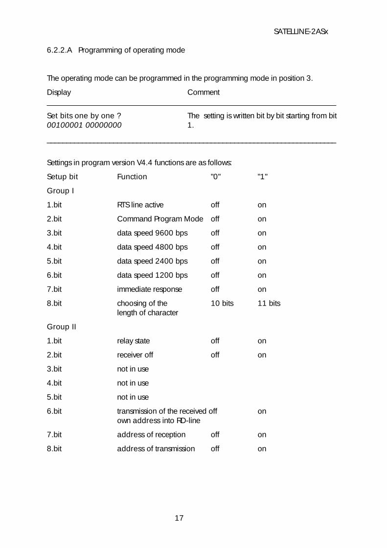
6.2.2.A Programming of operating mode
The operating mode can be programmed in the programming mode in position 3.
Display Comment__________________________________________________________________________
Set bits one by one ? The setting is written bit by bit starting from bit00100001 00000000 1.
__________________________________________________________________________
Settings in program version V4.4 functions are as follows:
Setup bit Function "0" "1"
Group I
1.bit RTS line active off on
2.bit Command Program Mode off on
3.bit data speed 9600 bps off on
4.bit data speed 4800 bps off on
5.bit data speed 2400 bps off on
6.bit data speed 1200 bps off on
7.bit immediate response off on
8.bit choosing of the 10 bits 11 bitslength of character
Group II
1.bit relay state off on
2.bit receiver off off on
3.bit not in use
4.bit not in use
5.bit not in use
6.bit transmission of the received off onown address into RD-line
7.bit address of reception off on
8.bit address of transmission off on
SATELLINE-2ASx
17

6.2.3.A Programming of channel
The selection of channel can be programmed in position 4.
Display Comment
___________________________________________________________________________
Set a new value ? c Set channel "C"
___________________________________________________________________________
Switching the radio data modem to other frequencies than specified in the instructionsis strictly forbidden. The use of non-approved frequencies can lead to prosecution bylocal authorities. Satel is not responsible for any illegal use of its radio equipment.
6.3.A Command program mode
If the command program mode is activated channel and address can be selected directlyfrom the serial port of the radio data modem without connecting pin 12 to ground. Thechange of settings is effected with the data speed and bit settings that are in current use.However the data part of the character must be 8 bits. The changes are effected with aprogramming packet, which is a separate packet and may not be included in thetransmitted data packet and may not include extra characters. The length of theprogramming packet should be 5 characters and the length of pause before and after theprogramming packet must be of 3 characters.
6.3.1.A Programming of address
Programming of both transmitting (Tx) and receiving (Rx) addresses is effectedsimultaneously by the command
SLAxy
where x and y are characters consisting of 8 bits.
Programming of only receiving address is effected by the command
SLRxy
and of the transmitting address only by the command
SLTxy.
SATELLINE-2ASx
18

After recognizing the packet of address programming the radio modem sets the CTS signalin a non-active state and saves the new address in the memory. If the saving is succesfullycompleted the radio modem answers by
OK
If the saving of the address is unsuccesful the modem gives an
Error
message.
6.3.2 Programming of channel
The programming of channel is effected by the commmand
SLC0x
where x is an ASCII character 0-9 or A-F announcing the required channel number. Afterrecognizing the packet for channel programming the radio modem sets the CTS signal inan non-active state and examines if the given channel is on the list of permitted channels. Ifthe channel is permitted the new channel is saved in the memory and the radio is set onthe required channel. If the saving is succesfully completed the radio modem answers by
OK
If the channel is not permitted or the saving is unsuccesful the modem gives an
Error
message.
7 Forming of the SL Command
By programming the radio modem with the SL command, please note that the form of theaddress is different than in the PROGRAM MODE. In PROGRAM MODE the address isgiven in hexadecimal (values between 0000 and FFFF) e.g. 2BFAh. By programming theradio modem by SL command the address consists of an address two 8 bit characters.
The radio modem requires the SL command as a continous packet. Either a file needs tobe created for the command or the application software designed for the radio modemmust take care of the continous transmission of the command. If there is a break in thetransmission the radio modem interprets the packets as transmitted data.
SATELLINE-2ASx
19
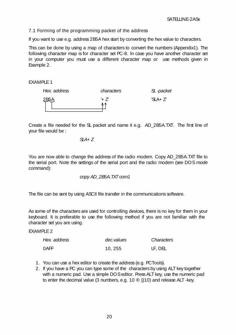
7.1 Forming of the programming packet of the address
If you want to use e.g. address 2B5A hex start by converting the hex value to characters.
This can be done by using a map of characters to convert the numbers (Appendix1). Thefollowing character map is for character set PC-8. In case you have another character setin your computer you must use a different character map or use methods given inExample 2.
EXAMPLE 1
Hex. address characters SL -packet
2B5A '+Z' 'SLA+Z'
Create a file needed for the SL packet and name it e.g. AD_2B5A.TXT. The first line ofyour file would be :
SLA+Z
You are now able to change the address of the radio modem. Copy AD_2B5A.TXT file tothe serial port. Note the settings of the serial port and the radio modem (see DOS modecommand):
copy AD_2B5A.TXT com1
The file can be sent by using ASCII file transfer in the communications software.
As some of the characters are used for controlling devices, there is no key for them in yourkeyboard. It is preferable to use the following method if you are not familiar with the character set you are using.
EXAMPLE 2
Hex. address dec.values Characters
0AFF 10, 255 LF, DEL
1. You can use a hex editor to create the address (e.g. PCTools). 2. If you have a PC you can type some of the characters by using ALT key together
with a numeric pad. Use a simple DOS editor. Press ALT key, use the numeric padto enter the decimal value (3 numbers, e.g. 10 ® 010) and release ALT -key.
SATELLINE-2ASx
20
e.g.
Hex. address typing of the corresponding decimal values
0AFF ALT (down) 0 1 0 ALT (release) ALT (down) 2 5 5 ALT (release)
7.2 Forming of the programming packet of the channel
If it is necessary to switch the channel to channel A (check that A responses to the correctfrequency required)
The file for switching the channel could be e.g. CHAN_A.TXT and the inhalt of the filewould in this case be :
SLC0A
You are now able to change the channel of the radio modem. Copy CHAN_A.TXT file tothe serial port (it is also possible to use the transfer of ASCII file in terminal programs).Note the settings of the serial port and the radio modem (see DOS mode command):
copy CHAN_A.TXT com1
NOTE ! THE SL COMMAND CAN NOT BE USED IN TERMINAL MODE.
YOU MUST CREATE A FILE CONTAINING THE SL COMMAND AND SEND THEFILE TO THE RADIO MODEM.
8 Multi Modem Data Systems
(Chapters 8 to 12 are general instructions applying to all radio modems manufactured bySATEL OY)
8.1 Required sequence of data characters
The data should be transferred in continuous sequences or in sequences divided intoblocks. Sequences that are too short (e.g. 1 character) should not be sent because"overhead-information" (synchronization plus terminal address) takes a great deal ofprocessing time and thus slows down the data transmission. The recommended length of adata packet is 50 - 500 characters.
The size of a system using one radio channel can be increased when the timeframe oftransmission of one terminal is short. This must be taken into account when planning the
SATELLINE-2ASx
21

system. The operating range of the system can be extended by increasing both the numberof base stations and the number of radio channels.
It is important that only one transmitter can be active on the same channel at the sametime.
8.2 Polling
The system can be configured as a "Master-Slave" network which allows one radio modemto control the others in the system. Slave units can communicate to the Master during thetime allocated to that Slave by the Master unit.
The advantage of the polling mode is that collisions (i.e. simultaneous transmissions) donot occur. The disadvantage of this method is that the transmitter of the Master is switchedon half of the time in situations, where there is no data transmission from mobile to Master.
A polling protocol is not included in the transparent radio modem. It is a protocol of higherhierarchy and supplied by the system.
8.3 Multi Master
The system can also be configured as a "Multi-Master" network. In this situation any radiodata modem can start transmission after first testing either by the CTS line or the CD linethat the radio channel is free.
The advantage of this system is that the transmitter is ON only during data transmission.The disadvantage is that if all the mobile stations do not "hear" each another collisions mayoccur.
A multi master protocol is not included in the transparent radio modem. It is a protocol ofhigher hierarchy and supplied by the system.
9 Planning a Radio Modem Network
9.1 Factors affecting quality and distance of the radio connection
v power of radio transmitterv sensitivity of radio receiverv tolerance of spurious radiations of the radio modulating signalv amplification of transmitting and receiving antennasv antenna cable rejectionv heightv natural obstaclesv interferences caused by radio frequencies
SATELLINE-2ASx
22

The transmitter power of the base model of SATELLINE-2ASx is 0.5 W and sensitivity ofreceiver more than -108 dBm. Thus in a flat area and in free space with a 1/4 waveantenna (antenna amplifcation 1dBi) and an antenna height of 1 m communications from3 km to 4 km can be achieved. Distances may be considerably shorter in situations wherethere are metallic walls or other material inhibiting the propagation of radio waves.
Over long distances, problems caused by natural obstacles can often be solved by raisingthe height of antennas. A ten fold increase in distance can be achieved with the use ofamplifying antennas. Frequent topographical variations over long distances may requirethat at least one of the antennas needs to be raised to a height of 10 to 20 m.
As the placement of the antenna at the base station is more than 10 m from the modem itis necessary to use a low loss cable (< 0.7 dB /10m ) in order not to waste the antennaamplification. Problematical connections can also be solved by adding anotherintermediate station for relay. In systems with many base stations an RSSI-signal wouldassist in choosing the best receiving base station. A communications network can also bebuilt with a combination of cables and radio data modems.
The SATELLINE-2ASx radio data modem operates in the 450 MHz band, whereinterference caused by human beings is insignificant. Long distance interferences need notto be taken into account even in special weather conditions.
The SATELLINE-2ASx eradicates normal levels of interference that occur. However,exceptionally high levels of interference can break through the safeguards and thus causeerrors on transmssion. In mobile vehicle applications the range of operation can beincreased by dividing the transmitted data into e.g. 50...500 bits blocks and byretransmitting defected blocks.
A sufficent safety margin can be obtained by testing communications using an extra 6 dBrejection at the antenna connection and with slightly less effective antennas than those tobe used in the final system.
9.2 Radio field strength
A successful radio transmission depends essentially on the radio field. Where field strengthis over a certain level the operational results are very good. Below this level, a few dBmarginal areas may occur in which errors begin to be generated by noise and interferencewhich will eventually lead to loss of connection.
Whilst in an open space, the field strength is at its optimum level, although it will still bereduced by distance. It must also be remembered that one open space has differentenvironmental and external factors to another, and that the affects on transmission qualitymust be taken into account when planning the system.
Ground, ground contours and buildings cause attenuation (loss of energy throughabsorbtion) and reflections of radio waves. Buildings reflect radio waves and therefore theaffects of attenuation are not as acute when transmission is over a short distance.
SATELLINE-2ASx
23
However, the reflected waves will suffer a loss in power once they travel over a certaindistance, this means that they combine with the direct radio waves and interact in eitherweakening or strenghtening the signal respectively. In reality attenuation can even occur at40 dB which is very sharp and the effect on the 450 MHz frequency is about 35 cmdifference.
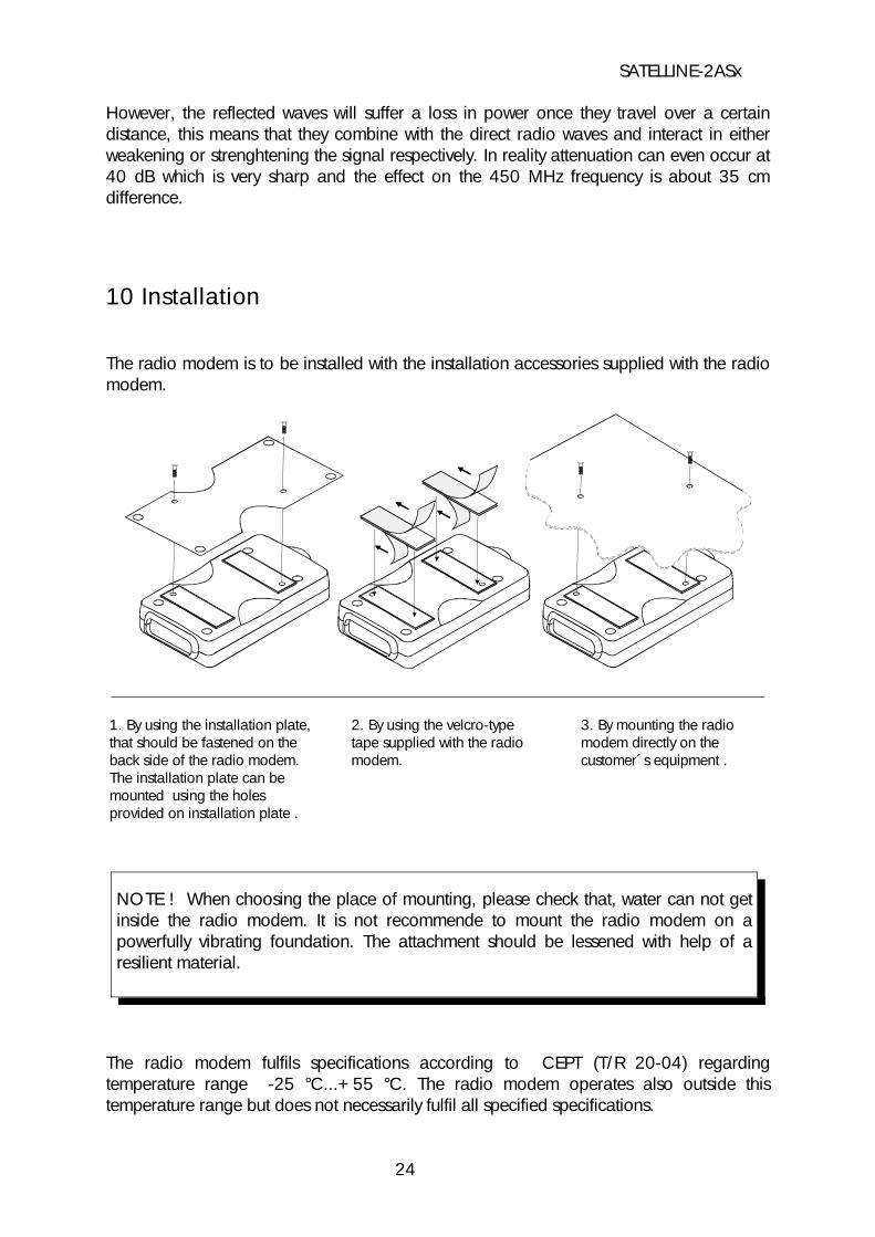
10 Installation
The radio modem is to be installed with the installation accessories supplied with the radiomodem.
3. By mounting the radiomodem directly on thecustomer´s equipment .
2. By using the velcro-typetape supplied with the radiomodem.
1. By using the installation plate,that should be fastened on theback side of the radio modem.The installation plate can bemounted using the holesprovided on installation plate .
NOTE ! When choosing the place of mounting, please check that, water can not getinside the radio modem. It is not recommende to mount the radio modem on apowerfully vibrating foundation. The attachment should be lessened with help of aresilient material.
The radio modem fulfils specifications according to CEPT (T/R 20-04) regardingtemperature range -25 °C...+55 °C. The radio modem operates also outside thistemperature range but does not necessarily fulfil all specified specifications.
SATELLINE-2ASx
24

10.1 RS-232 Interface
The radio modem is connected to terminal via RS-232 interface. A typical connectionwhere all handshaking lines are used is according to the figure below.
TD
RD
RTS
CTS
SGND
CD
DTR
+VbGND
11
9
13
6
7
2
1
15
8
+Vb GND
Radio modem
FUSE 630 mA slow
3
4
TD
RD
RTS
CTS
CD
2
3
4
5
7
8
25-PIN D-CONNECTOR
DTR20
DSR6SGND
TD
RD
RTS
CTS
CD
2
3
5
1
7
8
9-PIN D-CONNECTOR
DTR4
DSR6SGND
In some systems the radio modem is connected to another data transmission equipment(modem). The lines should in this case be connected accross according to the picturebelow.
TD
RD
RTS
CTS
CD
2
3
4
5
7
8
TD
RD
RTS
CTS
SGND
CD
DTR
+VbGND
11
9
13
6
7
2
1
158
+Vb GND
Radio modem
FUSE 630 mA slowDTR20
DSR6SGND
3
4
DSR 10
TD
RD
RTS
CTS
CD
2
3
5
1
7
8
9-PIN D-CONNECTOR
DTR4
DSR6SGND
25-PIN D-CONNECTOR
SATELLINE-2ASx
25

10.2 Supply of current
The nominal voltage of SATELLINE radio modems is 12 V. The range of voltage is 10 - 14V. Variations in the voltage below 1V are allowed as the radio modem is changing fromone mode to another. The operating voltage of the positive pole of the D 15 connector isconnected to the pins of the D connector and to the negative poles 7 and 8. The DTRline in position "1" can be used as an ON/OFF switch. In this case the logical state "1"(+5...+12 V) corresponds to ON and "0" (0 V...-12 V) to OFF.
The current consumption of SATELLINE-1ASl ja -1AS varies between 50 ... 250 mA and ofSATELLINE-2AS and -2ASx between 100 ... 600 mA. In systems where modelsSATELLINE-1ASl or -1AS have been changed to models SATELLINE-2AS tai -2ASx , currentsupply has to be checked. Especially in portable applications the DTR line of the radiomodem should be switched to position "0" when possible. In this case the currentconsumption is approx. 0.2 mA (SATELLINE-1AS and -1ASl) or 3 mA (SATELLINE-2ASand -2ASx).
NOTE POWER SUPPLY !
Even if the nominal output current of the power supply does not exceed it mighttemporarily be unstable as the current consumption changes e.g. at starting the poweramplifier. The outputs of power supplies are often supplied with sufficient outputcapacitance. The output capacitance of self built power supplies with regulators orswitched-mode power supplies might be insufficient or totally lacking.
Even if the nominal output current is considerably higher than the current consumptionof the radio modem, the voltage varies several voltages according to the changes ofthe current consumption of the radio modem. This kind of function of the power supplyweakens the function of the radio modem or prohibits it totally.
Supply current should be controlled in situations where the distance is short or theradio field strength is sufficient but the connection does not work or the number offaulty packets is big. Quick changes in voltage can not be measured with a multimeteras they often last for only approx. 0.5 ms. Therefore possible situations withundervoltage should be surveyed with an oscilloscope. To ensure a reliable operationof the radio modem the acceptable variation is below 1 V from the stable level andcontinuous oscillation below 50 mV.
NOTE! Whenever connecting RS-232 interface cables to equipment, theequipment MUST FIRST BE SWITCHED OFF.
SATELLINE-2ASx
26

10.3 Mounting the antenna
In great distances or in otherwise severe conditions the operation of radio communicationis dependent on antennas and their mounting. In antennas, antenna cables and terminaladaptors there should always be a gold plated connector. Since connectors of poor qualityoxidate and increase the attenuation in the course of time appropriate connectors andproper tools must always be used in mounting. One should also check that both theantenna and possible fitting elements resist well weather and environmental contamination.
The metal-free zone around small antennas should be at least 1/2 m and big antennas>5 m. The metal-free zone should be > 10 m around a relay antenna combination. Thismeans that if a large network of radio modems is to be installed the best place for theantenna is at the highest point of the building or even to use a radio mast. If a mast isused, the antenna can be installed using a side-installation up to 2 ...3 m away from themast itself.
When mounting the antenna pay also attention to possible sources of interference such as:v mobile phone network base stationsv local telephone network base stationsv television transmittersv radio linksv other radio modem networksv PC equipment (about a radius of 5 m from the antenna)
When ordering antennas please note that the antennas have been tuned to a certainfrequency range. Simple antennas and those made of stacked yagis are relatively wideband. The frequency range of the antenna becomes narrower the more elements there arein a yagi.
Keeping in mind the testing and service of the system it is generally useful to use rather along antenna cable in order to avoid the installation of radio modems near the antennainto a place possibly difficult to access.
The antenna cable should be chosen according to the lenght bearing in mind the followingrecommendations:
Length Type Attenuation < 5 m RG58 3.0 dB/10 m/450 MHz5 ... 20 m RG213 1.5 dB/10 m/450 MHz > 20 m Nokia RFX 1/2"-50 0.5 dB/10 m/450 MHz > 20 m AirCom+ 0.8 dB/10 m/450 MHz *)
*) AirCom+ cable is partly air insulated, thus an absolutely air tight connection between the cable and the connector is required.
SATELLINE-2ASx
27

In great distances when the antennas are in optical positions a 6 dB power marginal isadequate. Since the connection is built on the reflection and/or the knife-edge diffractionthe path loss can vary even 20 dB depending on the weather conditions. In this case ashort test can give a too positive result of the quality of the connection. Thus the height ofthe antennas and topographical obstacles must be surveyed with great care. From time totime an attenuating connection can be used if the data transmission protocol is wellprepared for this and the data transmission that occasionally slows down does not causeany problems to the process.
Vertical polarized systems (antenna elements are in vertical position) are often used in radio systems. In a system between a base station and sub-stations the vertical polarizationis generally recommendable. The antenna of the radio modem can not be mounted on thesame level with the other sub-station antennas in the same building. The best way todistinguish from the other antennas situated in neighbourhood is by mounting theantennas as far as possible from each other on the altitude level. The best result isgenerally obtained when all the antennas are in the same mast. With an extra groundplane between the antennas more distinction can be obtained between the antennas in themast.
A horizontal polarization can be used in data transmission between two points. With thepolarization attenuation more distinction is obtained in the vertical polarizationinterference. The influence of the directional patterns of the antennas must, however, betaken into consideration. If a distinction to another interfering antenna is wanted with thehorizontal polarized antennas there must be a good attenuation of the back lobe. Inaddtion to this the interfering radiator should be situated behind the antenna.
When the system does not demand the use of an omnidirectional antenna it isrecommendable to use directional antennas e.g. two-element yagis in firm externalinstallations. As the antenna amplification increases the setting of the direction of theantenna demands for a greater care.
The base stations in high places should be supplied with 4...6 degree band-pass filters. Please note that the higher the antenna the larger the broadcast area. The disadvantageswith a too high antenna installation at the base station are that interferences from a largerarea affect the base station and that the base station occupies the channel of a too largearea.
SATELLINE-2ASx
28

Example of an antenna installation: By use of amplifying antennas and by installingantennas in a high location, long distances can be reached with SATELLINE-2ASx.
11 Equipment
11.1 The connection of antennas to radio modems
Recommended antenna types are as follows:
11.1.1 Hand portable equipmentv 1/4 wave antenna ( wave length on 450 MHz is about 70 cm)v Helix antenna
The antennas are mounted directly on to the antenna connector (TNC) at the top of theradio modem.
11.1.2 Equipment installed in vehiclesv 1/4-wave antennav 1/2 wave antenna
Ideally the antenna should be installed vertically and it should have at least 0.5 m of openspace surrounding it. In a small system 1/4 wave antenna is adequate. There should be aground plane below the antenna (truck bonnet or roof). In weak conditions a 1/2 waveantenna is the most suitable. It can be mounted at the top of a pipe, as this provides it withas much open space as possible. In places where the antenna cannot be connected
SATELLINE-2ASx
29

directly to the TNC a 50 ohm coaxial cable must be used to provide the link between theTNC and the antenna.
11.1.3 Base station v omnidirectional (1/4, 1/2 or 5/8 wave antenna)v directional (yagi or corner reflecting antenna)
The antenna should be installed in an upright position. The exact location of the antennadepends on a number of factors from system size to physical fround countours. As ageneral rule, the antenna for a base station should be located at the highest point in themost central location of the system.
Alternatively the base station antenna can be situated inside the building, providing that thewalls of the building do not contain metal.
11.2 Cables
11.2.1 RF cables
If the antenna cable is shorter than 5 m a good quality 50 ohm RF cable can be used (e.g.RG58). If a longer cable is required, it need to be a low loss RF cable. As a standardcable we supply 50 ohm RG58 cable in lengths of 1 m (CRF-1) and 5 m (CRF-5).
NOTE ! Please check, that the contact area of cable connectors is gold plated and thatthe connectors used are reliable. Ageing connectors of poor quality oxidate easily andcause malfunction of the system.
11.2.2 Interface cables
When planning the location of the radio modem, it must be observed that the maximumlength of an RS-232 cable is 15 m. The cable must be shielded. The maximum length of the power supply cable is 2 m. As standard cables we supply cables with either a 25 pinconnector CRS-1 F or CRS-1 M (F=female, M=male) or with a 9 pin connector CRS-2 For CRS-2 M. The length of the cables are 2 m and they contain both interface and powersupply cables.
There is also an interface adapter ARS-1F with a programming switch and power supplycables available for the SATELLINE-2ASx radio modem. The interface adapter matches theconnector of the modem to a 9 pin (female) D connector. In addition there is a straightcable with 9 pin connector, CRS-9.
NOTE ! Please check, that the contact area of cable connectors is gold plated and thatthe connectors used are reliable. Ageing connectors of poor quality oxidate easily andcause malfunction of the system.
SATELLINE-2ASx
30

12 Check List
When installing and configuring a radio data modem following points should beconsidered:
1. Before connecting the RS-232 interface to equipment always check that the operating voltage is switched off.
2. Consider the exact location of the equipment for optimum resultsw Place the antenna in a free space as far as possible from any source of
interference w do not place the modem on a strongly vibrating surface w do not place the modem in direct sun light or high humidity
3. The capacity and stability of the power supply must be secured so that the current required by the transmitter is sufficient for creating a reliale connection.
4. The antenna is installated according to given instructions.
5. The settings of the radio modem correspond those of the terminal and all radio modems of the system have the same settings and are compatible to each other.
6. The radio modems are on the same channel.
SATELLINE-2ASx
31

Appendix 1 Character Map
SATELLINE-2ASx
32

Appendix 2A
Delays and reaction time of the RS-232 interface with a data speed of 9600 bps
TD
CTS
CD
RD
TD
CTS
CD
RD
t0t1 t3
t4
MODEM 1
MODEM 2 t4
t0 = 17 - 20 ms (typ. 18 ms) delay between TD and RD data
t1 = 4 - 10 ms Tx on / Rx CD delay
t2 = 2 - 10 ms (typ. 3 ms) Data package end delay
t3 = 10 -60 ms (typ. 30 ms) Tx buffers emptying time
t4 = 3 - 6 ms Rx to Tx connecting time
SATELLINE-2ASx
33

Appendix 2B
Delays and reaction time of the RS-232 interface with a data speed of 9600 bpsand immediate response
TD
CTS
CD
RD
TD
CTS
CD
RD
t0t1
t3t4
MODEM 1
MODEM 2
t0 = 17 - 20 ms (typ. 18 ms) delay between TD and RD data
t1 = 4 - 10 ms Tx on / Rx CD delay
t2 = 2 - 10 ms (typ. 3 ms) Data package end delay
t3 = 10 - 60 ms (typ. 30 ms) Tx buffers emptying time
t4 = 3 - 6 ms Rx to Tx connecting time
t5 = < 0,1 ms Virtual Rx to TX connecting time
t6 = t3 + (t4 - x) Tx buffer emptying time 2 (x = TD start time before t4)
t5 t6
t2
SATELLINE-2ASx
34

Table of Selectable Radio Channels
Channel Frequency Range (software settings)
(harware settings)F E D C B A 9 8 7 6 5 4 3 2 1 0
**x.200 - **x.575 MHz **x.200 **x.225 **x.250 **x.275 **x.300 **x.325 **x.350 **x.375 **x.400 **x.425 **x.450 **x.475 **x.500 **x.525 **x.550 **x.575**x.600 - **x.975 MHz **x.600 **x.625 **x.650 **x.675 **x.700 **x.725 **x.750 **x.775 **x.800 **x.825 **x.850 **x.875 **x.900 **x.925 **x.950 **x.975**y.000 - **y.375 MHz **y.000 **y.025 **y.050 **y.075 **y.100 **y.125 **y.150 **y.175 **y.200 **y.225 **y.250 **y.275 **y.300 **y.325 **y.350 **y.375**y.400 - **y.775 MHz **y.400 **y.425 **y.450 **y.475 **y.500 **y.525 **y.550 **y.575 **y.600 **y.625 **y.650 **y.675 **y.700 **y.725 **y.750 **y.775**y.800 - **z.175 MHz **y.800 **y.825 **y.850 **y.875 **y.900 **y.925 **y.950 **y.975 **z.000 **z.025 **z.050 **z.075 **z.100 **z.125 **z.150 **z.175
y = x + 1, z = x + 2
Hardware settings are made by the manufacturer. The frequency range of the equipment is marked on the label on the back of the r adiomodem.
Example: The channel of the radio modem has been set on A = 433.125 MHz as seen by switching the modem into programmingmode. The frequency range of the radio modem is 433.000 - 433.375 MHz (see the 3rd row at the table above). If the new channel should be e.g. 433.275 MHz, the channel 4 should be selected.
For more information of programming the radio modem: please see chapter 6.