sartorius comparator information this description is written for users who wish to connect their...
TRANSCRIPT

98647-000-53
SartoriusComparator
Interface Descriptionfor the CC Model Series


Contents
Page
General Information 4
General Specifications 5
Data Output Formats 6
Data Input Formats 11
Synchronization and Data Output Parameters 14
Settings for the Interface Parameters 17
Special Interface Functions 18
Pin Assignment Chart 19
Cabling Diagrams 20
Brief Instructions for Setting a Menu Code 22
Quick-Reference Guide to All Menu Code Settings 23
3

General Information
This description is written for users who wish toconnect their Sartorius Mass Comparator toa computer or a different peripheral device using thestandard V24/V28-RS232C(-S)*)/423 interfaceport on the mass comparator.
By using an on-line computer, you can change,activate and monitor the functions of the masscomparator.
You can plug an external remote-control switch intothe data interface port to activate these functions:print (data transfer), F1 or F2 key function, or tare.
If you interface an original Sartorius accessorydevice, such as a Sartorius Data Printer or asimilar unit, with a mass comparator that has thefactory-set menu codes, you do not need tochange any settings.
*) = Sartorius pin assignment
4

General Specifications
Type of interface Serial point-to-point connectorOperating mode Asynchronous, full-duplexStandard V28, RS232C, RS423 specificationHandshake *) 2-wire interface: via software (XON/XOFF)
4-wire interface: via hardware handshake linesClear To Send (CTS) and Data Terminal Ready (DTR)
Transmission rates *) 150, 300, 600, 1,200, 2,400, 4,800,9,600, 19,200 baud
Character coding 7-bit ASCIIParity *) Mark, space, odd, evenSynchronization 1 start bit; 1 or 2 stop bits *)Data output format *) 16 or 22 charactersof the balanceCharacter format *) – 1 start bit
– 7-bit ASCII– 1 parity bit– 1 or 2 stop bits
*) = can be changed by the user
5

Data Output Formats
Depending on the menu code setting: 7 2 1 = no data ID codeor 7 2 2 = data lD code,
data will be output with either 16 (code 7 2 1) or 22 (code 7 2 2) characters.
For a data output of 22 characters, a 6-character ID, as defined in the applicationprogram selected, precedes the 16 characters.
Data Output Format with 16 Characters
Display segments that are not activated (+ or – sign, leading zeros other than zerosbefore the decimal point) are output as spaces.
The following data block format is output according to what is displayed onthe balance:
1 2 3 4 5 6 7 8 9 10 11 12 13 14 15 16
* = space; E = unit
* * * * * * *+ – – – – – – – – – – – – – – – – – – – – – – – – – – –107 106 105 104 103 102 101 100 * * *0 0 0 0 0 0 0 0
* – – – – – – – – – – – – – – – – – – – – – – – – – – – * CR LF. . . . . . . .
– – – – – – – – – – – – – – – – – – – – – – – – – – – E E E– 106 105 104 103 102 101 100
0 0 0 0 0 0 0* * * * * * *
6
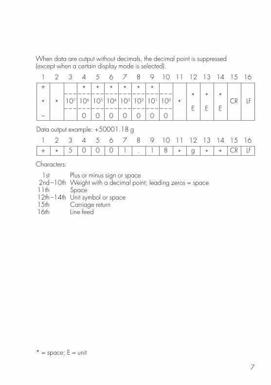
When data are output without decimals, the decimal point is suppressed(except when a certain display mode is selected).
1 2 3 4 5 6 7 8 9 10 11 12 13 14 15 16
Data output example: +50001.18 g
1 2 3 4 5 6 7 8 9 10 11 12 13 14 15 16
Characters:
1st Plus or minus sign or space2nd–10th Weight with a decimal point; leading zeros = space11th Space12th–14th Unit symbol or space15th Carriage return16th Line feed
* = space; E = unit
+ * 5 0 0 0 1 . 1 8 * g * * CR LF
+ * * * * * *– – – – – – – – – – – – – – – – – – – – – – – – * * *
* * 107 106 105 104 103 102 101 100 * CR LF – – – – – – – – – – – – – – – – – – – – – – – – E E E
– 0 0 0 0 0 0 0
7

– If the weighing system has not stabilized, no unit symbol is output.
– For the display format parameter “last numeral off or only at stability”(blank last numeral by a rounding factor of 10 or display last numeral when thereadout is stable), the 10th character in the string is a space. The reason:the last numeral without a decimal point is not blanked. Instead, it is givena definite zero; otherwise, the display would go completely blank when themass comparator is unloaded. In this case, you will obtain the standarddisplay format.
Unit symbols (standard mass comparator):
* * * No stability parameter t l s Singapore taelsg * * Grams t l t Taiwanese taelsk g * Kilograms g r * Grainsc t * Carats d w t PennyweightsI b * Pounds m g * Milligramso z * Ounces % * * Percento z t Troy ounces p c s Pieces (parts)t I h Hong Kong taels
* = space
8
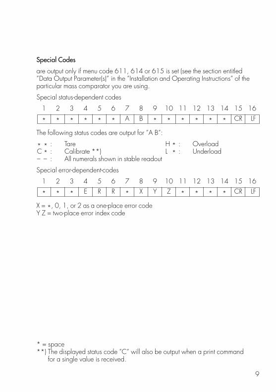
Special Codes
are output only if menu code 611, 614 or 615 is set (see the section entitled”Data Output Parameter(s)” in the ”Installation and Operating Instructions” of theparticular mass comparator you are using.
Special status-dependent codes
1 2 3 4 5 6 7 8 9 10 11 12 13 14 15 16
The following status codes are output for ”A B”:
* * : Tare H * : OverloadC * : Calibrate **) L * : Underload– – : All numerals shown in stable readout
Special error-dependent-codes
1 2 3 4 5 6 7 8 9 10 11 12 13 14 15 16
X = *, 0, 1, or 2 as a one-place error codeY Z = two-place error index code
* = space**) The displayed status code ”C” will also be output when a print command
for a single value is received.
* * * E R R * X Y Z * * * * CR LF
* * * * * * A B * * * * * * CR LF
9

Data Output with ID Code (Menu Code 7 2 2)
When data with an ID code is output, the ID code consisting of 6 charactersprecedes the data with a 16-character format.
During data output, all characters are shifted to the right by 6 characters.
1 7 22nd character
V = Plus or minus sign* = Spacex = DigitE = Unit. = Decimal pointK = Letter for an ID commentCR = Carriage returnLF = Line feed
When special codes are output (only if menu code 611, 614 or 615 is set),the letters ”Stat” for status code are assigned to the 1st through the 4th characters ofthe data string.
Status-dependent string:
1 7 13 14 22nd character
Error-dependent string:
1 7 10 11 12 14 15 16 22nd character
A, B = Status codesX = *, 0, 1 or 2 as a one-place error codeYZ = two-place error index code
S t a t * * * * * E R R * X Y Z * * * * CR LF
S t a t * * * * * * * * A B * * * * * * CR LF
K K K K K K V x x x x x x x x x * E E E CR LF* * * * * * * * . . . . . . * * *
10

Data Input Formats
Commands can be input via the mass comparator interface port to control thefunctions of application programs and of the mass comparator itself.
Control commands are distinguished according to those with upper-case letters orspecial characters and those with lower-case letters.
Format for Control Commands
Control commands can include up to 13 characters.
Each character must be transmitted with a start bit, a 7-bit ASCII-coded character, aparity bit and one or two stop bits.
You can define the parity, baud rate and handshake mode, including the number ofstop bits, by programming the codes in the operating menu of the mass comparator(see page 17).
Formats:
ESC = EscapeK = Command characterX = Number. = Decimal point– = UnderlineCR = Carriage returnLF = Line feed
The characters CR and LF do not have to be transmitted in the data string.
ESC K X X X X X X X X – CR LF. . . . . .
ESC K X – CR LF
ESC K CR LF
11

Control Commands with Upper-Case Letters or Special Characters
Acoustic signal
Self-test
Tare
The commands ”P” through ”T” do not affect the code settings of theoperating menu. The command ”S” causes the processor to reinitialize (turns themass comparator off and back on again).
The mass comparator will operate according to the commands available up untilthe processor is reinitialized. Once the mass comparator has been turned on, theprocessor will always recognize the codes entered by the user in the operating menu.
Block keypad
Release keypad
Adaptation to Ambient Conditions
Very stable
Stable
Unstable
Very unstableESC N CR LF
ESC M CR LF
ESC L CR LF
ESC K CR LF
ESC R CR LF
ESC O CR LF
ESC T CR LF
ESC S CR LF
ESC Q CR LF
ESC P CR LF
12

Control Commands with Lower-Case Letters
All functions that can be selected by pressing the appropriate keys on the masscomparator or the control unit can also be activated by commands.
Standard:
function key
function key
function key
function key
info function
clear function
Each control command with the lower-case letters (such as f and s) must beterminated by an underline (ASCII = 5F Hex).
ESC s 3 – CR LF
ESC s 0 – CR LF
ESC f 6 – CR LF
ESC f 2 – CR LF
ESC f 1 – CR LF
ESC f 0 – CR LF
13

Synchronization and Data Output Parameters
Definition
During data communication between the mass comparator and an on-line device(computer), ”telegram-style” information consisting of ASCII characters istransmitted by the interface.
For error-free data communication, the interface parameters, including the baud rate,parity and handshake mode, as well as the character format, must be the samefor both units.You can change these parameters in the operating menu of the mass comparatorso that they match those of the on-line device.In addition to these parameter settings, you can define the data output parameter ofthe mass comparator so that data are transmitted depending on various conditions –for more information, see the ”Installation and Operating Instructions” of themass comparator you are using.
If you do not plug a peripheral device into the interface port on themass comparator, this will not generate an error message. In this case,data will be output but not received.
Handshake
The mass comparator interface (Sartorius Balance Interface = SBI) has a 23-bytetransmit buffer and a 40-byte receive buffer.
You can access the operating menu of the mass comparator to define varioushandshake parameters:
Software handshake: controlled by ”XOFF” and ”XON”
Hardware handshake: – after ”CTS” send 2 characters– after ”CTS” send 1 character
What happens when you define a software handshake?
Receiving device:
”XOFF” will not be transmitted until the receive buffer has stored the 26th character.The enable command ”XON” is given after the buffer has transmitted allcharacters up to the 14th character.
14

If the device addressed does not understand the control command, the SBIreceiving device will continue to operate additionally with a hardware handshakeafter it has received another 6 characters.
For data communication with a software handshake, ”XON” must be sent bya device when it is turned on in order to enable another on-line deviceto exchange data.
Sequence:
Transmitting device Receiving devicemass comparator
– – – – – byte – – – – →– – – – – byte – – – – →– – – – – byte – – – – →– – ← – – – <XOFF> – – – – –– – – – – byte – – – – → (Once <XOFF> is transmitted, a maximum– – – – – byte – – – – → of 14 bytes can still be received.)
: :: Pause :: :: :
– – ← – – – <XON> – – – – – –– – – – – byte – – – – →– – – – – byte – – – – →
Transmitting device:
The importance of such handshake control for data transmission becomesespecially apparent– when the continuous automatic data output parameter is defined– when data output is controlled by application programs.
Once <XOFF> is received, it prevents further transmission of characters. When<XON> is received, it re-enables the transmitting device to send data. Thetransmitting device is always enabled for sending data after it has been switched on.
If data transmission is interrupted by the control line (CTS) or the command<XOFF> while a data block is being output from an application program (only forprinting a section of text with several lines of data), the readout will be locked intothe display at the same time.
Data output will be blocked until the interface receives an enabling signal.
15

Activating a Data Output Process
You can define the data output parameter so that output is activated when a printcommand is received, or is activated automatically. You have two options for theautomatic mode: data output can be either synchronous with the mass comparatordisplay or activated at defined intervals (to select the parameter, see the”Installation and Operating Instructions”).
Data Output by Print Command
The print command can be transmitted by a software command orby pressing the print key.
You can connect an external universal switch for remote control to the masscomparator interface port (for the print function, see the ”Installation and OperatingInstructions”) in addition to an interface cable for a different device. For the switch,use pins 8 and 15 of this port and a cable up to 1.5 m or 5 ft long.
If data output is requested by a software command (see the section on”Data Input Formats”), you can install a 15 m (50 ft) cable for RS232C ora 300 m (984 ft) cable for RS423.
Automatic Data Output
In the ”auto print” operating mode, the data are output to the interface port withoutrequiring a print command. You can choose to have data output automatically atdefined print intervals with or without the stability parameter. Whichever parameteryou choose, the data will be output as the readouts appear on the masscomparator display.
If you select the auto print setting, data will be transmitted immediately the momentyou turn on the mass comparator. Automatic data output can be stopped andrestarted either when you press the print key, or when an external print commandis received, if you have set menu code 6 2 1.
16

Settings for the Interface Parameters
Baud Rate Code
150 baud 5 1 1300 baud 5 1 2600 baud 5 1 3
1,200 baud * 5 1 42,400 baud 5 1 54,800 baud 5 1 69,600 baud 5 1 7
19,200 baud 5 1 8
Parity Code
Mark parity 5 2 1Space parity 5 2 2Odd parity * 5 2 3Even parity 5 2 4
Number of Stop Bits Code
1 stop bit * 5 3 12 stop bits 5 3 2
Handshake Mode Code
Software handshake 5 4 1Hardware handshake with 2 characters after CTS * 5 4 2Hardware handshake with 1 character after CTS 5 4 3
* = factory setting
17

Special Interface Functions
Data Input/Output to/from the Female Interface Connector
You can plug an external switch for remote control into the female interfaceconnector (such as foot switch YPE 01 RC with the two functions ”tare” and ”print”).If you change the menu code setting, you can interface both a control unit displayand our universal remote-control switch to your mass comparator.
Pin assignment for the female interface connector:
Pin Standard Switch Function Universal Switch Function(Code 8 10 2) (Code 8 10 1)
15 Print ”Universal switch” (see below)17 F1 key Not connected18 F2 key Not connected19 Tare Not connected
Interface function Code
Universal remote-control switch 8 10 1Standard switch * 8 10 2
External, Universal Remote-Control Switch (only with Code 8 10 1)
You can plug an external, universal remote-control switch into the interfaceport on the mass comparator.
To change the function of this switch, set the appropriate menu code listed below.
Functions Code
Print * 8 4 1Tare 8 4 2F1 key 8 4 3F2 key 8 4 4
* = factory setting
18

Print/ Not F1 Key F2 Key TareUniversal ConnectedSwitch*)
Pin Assignment Chart
Female Interface Connector:
25-position D-submini, DB25S with screw lock hardwarefor cable gland
Male Connector Required: (please use connectors with the same specifications)
25-pin D-submini, DB25S, with shielded cable clamp assembly(Amp type 826 985-1C) and fastening screws (mate screws for female screw lock,Amp type 164 868-1)
Pin Assignment:
Pin 1: Signal GroundPin 2: Data Output (TxD)Pin 3: Data Input (RxD)Pin 4: ”Signal Return” (TxD/RxD)Pin 5: Clear to Send (CTS)Pin 6: Internally ConnectedPin 7: Internal GroundPin 8: Internal GroundPin 9: Reset – In**)Pin 10: –12 VPin 11: +12VPin 12: Reset–Out**)Pin 13: +5 VPin 14: Internal GroundPin 15:Pin 16:Pin 17:Pin 18:Pin 19:Pin 20: Data Terminal Ready (DTR)Pin 21: Supply Voltage Ground ”COM”Pin 22: Not ConnectedPin 23: Not ConnectedPin 24: Supply Voltage Input +15..25 VPin 25: +5 V
*) = To change the pin assignment, see ”Data Input/Output to/from the FemaleInterface Connector” on page 18
**) = Hardware restart
19

Cabling Diagrams
Diagram for interfacing a computer or a different peripheral deviceto the mass comparator using the RS 232 C/V24 standard and interface cablesup to 15 m (50 ft) long
Mass Comparator Peripheral Device
Type of cable: AWG 24 specification
20

Diagram for interfacing a peripheral device to the mass comparator usingthe RS 423/V10 standard and interface cables up to 300 m (984 ft) long
Mass Comparator Peripheral Device
Type of cable: AWG 24 specification
*) The protective ground is on one side only
21

Brief Instructions for Setting a Menu Code
Turn your mass comparator off and then back on again.While all segments are displayed, briefly press the tare control.
If ”-L-” is displayed, change to the ”-C-” mode using the menu access switch.
Select the desired code number as follows:
– press to increase it or
– to decrease it.
Select the left-hand, middle or right-hand placeas follows:
– press the key to go toward the left
– press the key to go toward the right
Confirm your code selection by pressingthe tare control .
Adjust the menu access switch back to the originalsetting – readout: -L-.
To leave the menu, press .
22

Quick-Reference Guide to All Menu Code Settings
This list of menu parameters compiled from the ”Installation and OperatingInstructions” of your mass comparator gives you a quick-reference guideto the code settings.If you need to change any of the factory settings, we recommend that you enterthese changes along with the date and, if necessary, your initials under the columnheading ”Changes.”
Interface Parameters
* = factory setting
23
Baud Rate Code Changes150 baud 5 1 1300 baud 5 1 2600 baud 5 1 3
1,200 baud 5 1 4 *2,400 baud 5 1 54,800 baud 5 1 69,600 baud 5 1 7
19,200 baud 5 1 8
Handshake Mode Code ChangesSoftwarehandshake 5 4 1Hardwarehandshake with2 charactersafter CTS 5 4 2 *Hardwarehandshake with1 characterafter CTS 5 4 3
Parity Code ChangesMark parity 5 2 1Space parity 5 2 2Odd parity 5 2 3 *Even parity 5 2 4
Number ofStop Bits Code Changes1 stop bit 5 3 1 *2 stop bits 5 3 2

Utilities Additional Parameters
* = factory setting
24
Data Output Parameter ChangesW/o stability 6 1 1After stability 6 1 2 *At stability 6 1 3Auto w/o stability 6 1 4Auto after stability 6 1 5
Data Input/Outputvia Interface Code ChangesUniversal switch 8 10 1Standard switch 8 10 2 *
Data ID Codes Code ChangesWithout 7 2 1 *With 7 2 2
Print Interval after Changes1 disp. update 6 3 1 *2 disp. updates 6 3 25 disp. updates 6 3 3
10 disp. updates 6 3 420 disp. updates 6 3 550 disp. updates 6 3 6
100 disp. updates 6 3 7
Automatic Data Output ChangesStop with key 6 2 1Not stoppable 6 2 2 *
Auto Tare after Data Output ChangesOff 6 4 1 *On 6 4 2
Universal Switch(only forcode 8 10 1) Code ChangesPrint 8 4 1 *Tare 8 4 2F1 key 8 4 3F2 key 8 4 4

Sartorius AGb 37070 Goettingen, Germanyp Weender Landstrasse 94–108, 37075 Goettingen, Germanyt (+49/551) 308-0, f (+49/551) 308-3289Internet: http://www.sartorius.com
Copyright by Sartorius AG, Goettingen, Germany. All rights reserved. No part of this publication may be reprinted or translated in any form or by any means without the prior written permission of Sartorius AG.
The status of the information, specifications andillustrations in this manual is indicated by the dategiven below. Sartorius AG reserves the right tomake changes to the technology, features,specifications and design of the equipmentwithout notice.
Status: June 1993, Sartorius AG, Goettingen, Germany
Printed in Germany on paper that has been bleached without any use of chlorine · W5A00O · KTPublication No.: WYD6075-a93061