sandia brazing research and modeling capabilities* library/research/coal/energy systems...july 8-9,...
TRANSCRIPT
SECA SOFC Seal MeetingJuly 8-9, 2003
Sandia Brazing Research and Modeling Capabilities*
F. Michael HoskingMaterials and Process Sciences Center
Sandia National LaboratoriesAlbuquerque, NM 87185-0889
* Sandia is a multiprogram laboratory operated by Sandia Corporation,a Lockheed Martin Company, for the United States Department of Energy’s
National Nuclear Security Administration under Contract DE-AC04-94AL85000.
Principal SNL/NM Technical Brazing ContactsMetals: Mike Hosking & John Stephens, Org. 1833 & Chuck Walker, Org. 14171
Ceramic: Ron Loehman, Jill Glass & Sandy Monroe, Org. 1843Microanalysis: Joe Michael, Tom Headley, Paul Kotula & Paul Hlava, Org. 1822
Modeling: Steve Burchett, Frank Dempsey, Rick Givler & Jerry Wellman, Org. 9100

SECA SOFC Seal MeetingJuly 8-9, 2003
Brazing is widely used to join metals and ceramics to each other for a variety of high reliability components
New active brazing alloys simplify hermetic joining issues
Basis: Oxide-forming additives to filler metal (e.g., V, Ti, Zr, Hf) promote direct wetting and adhesion to the ceramic materials (Al2O3, Si3N4, cermet, …)
Payoff: Eliminate complex Mo-Mn metallize / Ni-plate & related processing for conventional alloys
Issue: Complex reactions between active braze elements and ceramic/metal base materials need to be understood to control and optimize process
• headers• connectors• feedthroughs• thermal batteries• high voltage tubes• electromechanical devices• storage containers
TEM ImageTEM Image
TiO, Ti2O & Cu3Ti3O reaction products

SECA SOFC Seal MeetingJuly 8-9, 2003
Braze flow visualization and dissolution reactions are important components in understanding the braze process
x distanceto
LabVIEW + IMAQ Vision Analysis
∆x = 0.19 mm
≈ 10 D (1.3 mm)
Laminar Flow
approx. 5 Hz
x distanceto
LabVIEW + IMAQ Vision Analysis
x distanceto
LabVIEW + IMAQ Vision Analysis
∆x = 0.19 mm
≈ 10 D (1.3 mm)
Laminar Flow
approx. 5 Hz
Recent Accomplishments• Conference paper / presentations (IBSC’03;
CSM Materials Science Seminar; C6 ASCI Solidification Working Group)
• S&T of Welding & Joining journal paper• In-Situ Visualization of Braze Flow patent
1095ºC
1145ºC1120ºC
(at% Ni)
1095ºC
1145ºC1120ºC
(at% Ni)
66019010181140 (H2Frn)
321020181145
1.519514121120
0.5175631095
ResidentTime Above
1085ºC
JointThickness
(µm)
EMPA Ni Content(wt. %)
Terminal Solidus
(wt. % Ni)
Specimen Temperature
(ºC)
66019010181140 (H2Frn)
321020181145
1.519514121120
0.5175631095
ResidentTime Above
1085ºC
JointThickness
(µm)
EMPA Ni Content(wt. %)
Terminal Solidus
(wt. % Ni)
Specimen Temperature
(ºC)
Note: At 1145ºC, Cliquidus ~ 10 wt. % Ni
0
20
40
60
80
100
0 1000 2000 3000 4000 5000
Ni
Cu
Con
cent
ratio
n (w
t. %
)
distance (µm)
Cu-Ni Traces Through Center of Cu Braze1120C Peak Work Temperature
1120ºC
EMPA Traces
1120ºC
EMPA Traces
Cu-Ni binary braze flow & dissolution experiments
Braze Capillary Flow Visualization

SECA SOFC Seal MeetingJuly 8-9, 2003
Active brazing technology is bridging a wide range of needs because of the fundamental knowledge being developed
0
20
40
60
80
100
120
Frac
ture
Stre
ngth
(M
Pa)
94% 94% 94%99.8% 99.8% 99.8%
Au - 16.0Ni -1.75V - 0.75Mo
Au - 18.0Ni - 0.8Ti
Au -17.5Ni - 2.5Ti
Alumina ceramic / braze interface reactions vary significantly with active element
Alumina
Au-Ni-Mo-2V
reaction layer
10 nm
XX--ray diffractionray diffraction
(Fe, Ni,Co)3Ti
… no TiAlumina
Kovar (Fe-29Ni-17Co)
Ag-Cu-Ti
Competing reactions between dissimilar base materials can introduce unwanted results
V activation
Ti activation… compatibility
issuesZr activation
Alumina
Au-Ni-Mo-2V
reaction layer
10 nm
XX--ray diffractionray diffraction
(Fe, Ni,Co)3Ti
… no TiAlumina
Kovar (Fe-29Ni-17Co)
Ag-Cu-Ti
Competing reactions between dissimilar base materials can introduce unwanted results
V activation
Ti activation… compatibility
issuesZr activation
Fracture strengths for 94 & 99.8% alumina brazed with Ti & V-bearing Au-Ni filler metals exhibit dependency on glassy phase and more stable TiOx reaction product
Ag-2Zr (wt. %) ABA
reaction layer
Alumina
ZrO2
15 µm

SECA SOFC Seal MeetingJuly 8-9, 2003
A multidisciplinary approach to characterizing the different brazing reactions and properties is necessary for success
0
20
40
60
80
100
120
140Average Tensile Strength (MPa)
BrazingTemperature
& Time
Determining effects of reaction products & microstructures on properties (hermeticity & strength) as a function of active element (thermodynamics / kinetics), base material (adhesion / dissolution), brazing conditions (temperature, time, atmosphere, heating cycle& gradients, orientation), surface preparation (ceramic air-firing).
Contact Angle vs. [SiO2]
0
10
20
30
40
50
60
70
80
0 20 40 60 80 100
[SiO2]
Wet
ting
Ang
le
2.5%Hf3.4%Hf6.8%Hf
1100°C for 30 min in Ar
Contact Angle vs. [SiO2]
0
10
20
30
40
50
60
70
80
0 20 40 60 80 100
[SiO2]
Wet
ting
Ang
le
2.5%Hf3.4%Hf6.8%Hf
Contact Angle vs. [SiO2]
1100°C for 30 min in Ar
0
10
20
30
40
50
60
70
80
0 20 40 60 80 100
[SiO2]
Wet
ting
Ang
le
2.5%Hf3.4%Hf6.8%Hf
1100°C for 30 min in Ar
200 µm
96% Al2O3
Ag-2.5 wt.% Hf
200 µm96% Al2O3
200 µm
96% Al2O3
200 µm
96% Al2O3
Ag-2.5 wt.% Hf
200 µm96% Al2O3
Ag-2.5 wt.% Hf
200 µm96% Al2O3
200 µm
96% Al2O3
Ag-2.5 wt.% Hf
200 µm96% Al2O3
200 µm
96% Al2O3
200 µm
96% Al2O3200 µm96% Al2O3
Ag-2.5 wt.% Hf
200 µm96% Al2O3
Ag-6.8 wt. % Hf
ASTM F19Test Specimen
ASTM F19Test Specimen
Al-500 alumina brazed with Ag-3.4Hf & 0.25 mm Kovar™

SECA SOFC Seal MeetingJuly 8-9, 2003
Ability to correlate braze interface reactions with desired properties will yield more producible & reliable joints
0
21
42
63
84
105
0 20 40 60 80 100
AlSiFeCoNiAgHf
Co
nce
ntr
atio
n (
wt.
%)
Distance (µm)
Job #PBR02014Disk 2file 95
P. F. Hlava020207
Trace From Kovar Through Ag - 3.4Hf Braze Alloy into Alumina (Trace 3)Sample Brazed 990°C/10 min., dry H
2
BSE image shows continuous HfO2reaction layer at ceramic interface Kovar AL-500
0
21
42
63
84
105
0 20 40 60 80 100
AlSiFeCoNiAgHf
Co
nce
ntr
atio
n (
wt.
%)
Distance (µm)
Job #PBR02014Disk 2file 95
P. F. Hlava020207
Trace From Kovar Through Ag - 3.4Hf Braze Alloy into Alumina (Trace 3)Sample Brazed 990°C/10 min., dry H
2
BSE image shows continuous HfO2reaction layer at ceramic interface Kovar AL-500Kovar AL-500
Single crystal sapphire & polycrystalline alumina brazed with Ag-2Zr
94% alumina brazed with Ag-2Zr is hermetic, fails in the bulk ceramic and has 130 MPa tensile strength
Ag-3.4Hf ceramic braze joints also demonstrate similar excellent properties (hermetic & 125 MPa)
Recent Accomplishments• Implementation of active brazing in production• Conference paper / presentations (ASM Materials
Solutions 2002; AWS IBSC’03; ACerS 2003)• Metallurgical Transactions A paper (in publication)• Coating System for Direct Ceramic Brazing patents

SECA SOFC Seal MeetingJuly 8-9, 2003
Diffusion bonding offers an alternative joining processCeramic-metal and metal-metal joints are possible
a) Hard ceramic and comparatively soft metal surfaces come in contact (T, t, P)
b) Metal surface yields under high local stressesc) Deformation continues mainly in the metal,
leading to interface diffusion & void shrinkaged) Metallurgical bond is formed
TWI, Ltd, 2000.
SECA SOFC Seal MeetingJuly 8-9, 2003
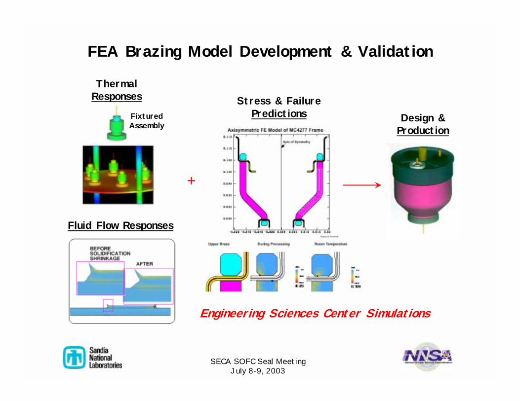
FEA Brazing Model Development & Validation
ThermalResponses Stress & Failure
Predictions
Fluid Flow Responses
Design &Production
FixturedAssembly
+
Engineering Sciences Center Simulations

SECA SOFC Seal MeetingJuly 8-9, 2003
FEA Thermal Modeling of Furnace Brazing
Work Rack & Parts
• Nonlinear, 3-D transient thermal finite element code
• Ability to mesh very fine details (large node and surface radiation enclosure)
Typical Model Inputs• materials density• thermal conductivity• specific heat• emissivity• thermal boundary
conditions• convective heating by hydrogen
gas is assumed negligible• heating driven by radiation from
furnace elements & conductionfrom Mo shelves to work piece Simulations processed on massively
parallel teraflop compute server

SECA SOFC Seal MeetingJuly 8-9, 2003
Example: Two-Step, Cu + 50Au-50CuBraze Assembly Process Characterization
Oven - 1/2 section
FEA Thermal Model
Shelves/fixtures
backup ringweight
housingweight
fixture alignment
backupring
Au-Cu2nd Braze
Cu1st Braze
base
large flange
small flange
pins
housing frame
backupring
Braze Fixture
ceramic ring
SECA SOFC Seal MeetingJuly 8-9, 2003
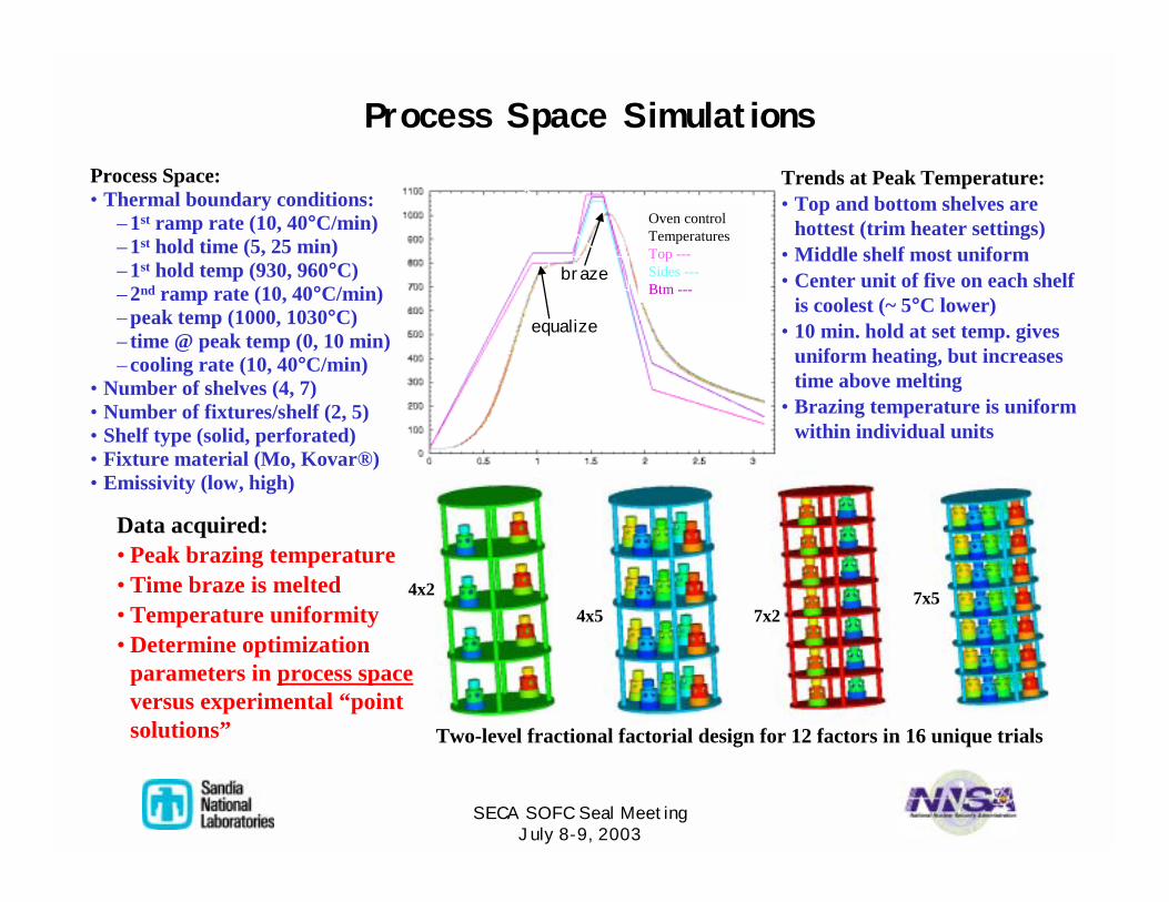
Process Space Simulations
braze
Oven control TemperaturesTop ---Sides ---Btm ---
equalize
Data acquired:• Peak brazing temperature• Time braze is melted• Temperature uniformity• Determine optimization
parameters in process spaceversus experimental “point solutions”
Trends at Peak Temperature:• Top and bottom shelves are
hottest (trim heater settings)• Middle shelf most uniform• Center unit of five on each shelf
is coolest (~ 5°C lower)• 10 min. hold at set temp. gives
uniform heating, but increases time above melting
• Brazing temperature is uniform within individual units
4x24x5 7x2
7x5
Process Space:• Thermal boundary conditions:
– 1st ramp rate (10, 40°C/min)– 1st hold time (5, 25 min)– 1st hold temp (930, 960°C)– 2nd ramp rate (10, 40°C/min)– peak temp (1000, 1030°C)– time @ peak temp (0, 10 min)– cooling rate (10, 40°C/min)
• Number of shelves (4, 7)• Number of fixtures/shelf (2, 5)• Shelf type (solid, perforated)• Fixture material (Mo, Kovar®)• Emissivity (low, high)
Two-level fractional factorial design for 12 factors in 16 unique trials
SECA SOFC Seal MeetingJuly 8-9, 2003
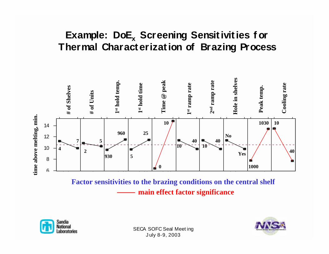
Example: DoEx Screening Sensitivities forThermal Characterization of Brazing Process
h l it O h ld H th ld P th ld 1 2 h l T k t6
8
1 0
1 2
1 4
Factor sensitivities to the brazing conditions on the central shelf
47
2
525
5
960
930
0
40
10
1040
No
1030
Yes
1000
40
10
main effect factor significance
# of
She
lves
1stho
ld te
mp.
1stho
ld ti
me
Tim
e @
pea
k
1stra
mp
rate
2ndra
mp
rate
Hol
e in
shel
ves
Peak
tem
p.
Coo
ling
rate
# of
Uni
ts
time
abov
e m
eltin
g, m
in.
10