sanders pre-cast concrete systems, inc. pre-cast concrete systems, inc. 6051 south indianapolis road...
TRANSCRIPT

THE SANDERS COMPANIES
09/18/15
DATE
TITLE AND INDEX OF SHEETS
DATE
APPROVED BY:
ISSUED FOR REVIEW09-18-15
REVISIONS/ISSUE
SANDERS PRE-CAST CONCRETE SYSTEMS, INC.
6051 SOUTH INDIANAPOLIS ROAD
WHITESTOWN, IN 46075
PROJECT NO.:
PROJECT
OF
SHEET
CONTRACT NO.:
PR#
IR-XX
1 14
SPC-#
THESE DRAWINGS CONTAIN PROPRIETARY INFORMATION
WHICH MUST NOT BE TRANSMITTED TO ANY PERSON OR
FIRM NOT INVOLVED WITH THIS PROJECT EXCEPT BY
WRITTEN PERMISSION OF THE SANDERS COMPANIES
FLORIDA DEPARTMENT OF TRANSPORTATION
6051 South Indianapolis RoadWhitestown, IN 46075
(800) 769-5503 toll free317-769-3712 fax
Concrete Systems, Inc.Sanders Pre-Cast
MSE WALL SYSTEM SUBMITTAL

FOR APPROVAL:
RECOMMENDED
DESIGN ENGINEERDATE
DESIGNED:
CHECKED:
DRAWN:
CHECKED:
PROJECT NO.:
PROJECT
OF
SHEET
CONTRACT NO.:
SCALE
PR#
IR-XX
2 14
SPC-#As Noted
JEM JEM
ZSS ZSS
GENERAL NOTES
System Submittal
Florida
09/18/15
GENERAL NOTES
Design Criteria
1) Design is based on the assumption that the material within the reinforced earth volume, methods of construction
and quality of prefabricated materials shall conform to the contracting agency's specification for
Mechanically-Stabilized Earth (MSE) walls.
2) Soils characteristics assumed for design:
Sand Backfill
Ø = 30 degrees, γ = 105 lbs/cu ft, and corrosivity properties satisfying the specifications
Limerock Backfill (Miami-Dade and Monroe Counties only)
Ø = 34 degrees, γ = 115 lbs/cu ft, and corrosivity properties satisfying the specifications
3) The maximum contact pressure under static conditions at the foundation level is as shown on the wall elevation
sheets for each design case. It is the responsibility of the owner to determine that the resistance to this contact
pressure is provided for that location.
4) Any unsuitable foundation material below the reinforced earth volume, as determined by the owner, shall be
excavated and replaced with suitable material in a controlled manner or otherwise stabilized as directed by the
owner.
5) Concrete reinforcing bars shall be ASTM A615 Grade 60, uncoated.
6) Concrete for precast panels shall have a minimum compressive strength after 28 days of 4,000 psi for Wall Type
2A, 5,500 psi for Wall Types 2B-F. Concrete shall meet the requirements of the concrete class called out in
FDOT Index 6020.
7) The soil reinforcement strips shall meet ASTM A572, Grade 65 and are galvanized per ASTM A123, Coating
Grade 85 or ASTM B695, Class 80. Panel embeds shall meet ASTM A1011, Grade 65 and galvanized
according to ASTM A123. Minimum galvanizing thickness shall be 3.4 mils.
8) Minimum panel design thickness is 5½ inches.
Wall Construction
9) Soil reinforcing strips and related hardware shall be supplied by Sanders Pre-cast Construction Products, Inc.
10) Stations and offsets are referenced to the contract plans.
11) MSE walls in curves will form a series of short chords of 10 ft each to match desired wall alignment.
12) For location and alignment of MSE walls, see contract plans.
13) If manholes and drop inlets are present, they shall be located as shown in the contract plans.
14) Where drainage structures are proposed adjacent to the base of the walls, the edge of the unreinforced
concrete leveling pad shall be constructed flush with the face of the wall panels. For locations and details of
drainage structures, see wall elevations and contract plans.
15) Backfill material shall be compacted in accordance with the specifications. Installation of reinforcing strips
shall be permitted only after placement and compaction of each underlying lift of the backfill material has
reached the required level. Backfill to be placed in max compacted lifts of 6 in. Backfill must be level with the
panel embed prior to strip installation.
16) Compaction and operation equipment shall be kept a minimum distance of 3 ft. from the back face of the MSE
wall panels. Compaction within 3 ft. of the panels shall be achieved with at least five passes of a lightweight
mechanical tamper, roller or vibratory system. No compaction density tests shall be taken within the 3 ft. of
the panels.
17) It is recommended that where walls are in excess of 20 ft. in height, the finished grade in front of the wall shall
be placed and compacted as soon as possible or before wall reaches three panels high. Fill and/or backfill per
specifications.
18) It is the contractor's responsibility to determine the location of any posts for guardrails, handrails, and similar
elements behind the MSE wall panels. Prior to placement of the top layer of reinforcing strips, individual strips
may be skewed to avoid the post locations if authorized by Sanders Pre-cast Construction Products, Inc. Any
damage done to the reinforcing strips due to the installation of posts shall be repaired by the contractor at the
contractor's expense.
19) Reinforcing strips shall be placed perpendicular to the MSE wall panels. The plan placement of reinforcing
strips may be skewed up to 15 degrees horizontally and/or vertically in order to avoid conflicts with existing or
future structures, pipes, underdrains, foundations or posts. If the required skew exceeds 15 degrees and
specific direction has not been provided on the plans, the contractor shall notify Sanders Pre-cast Construction
Products, Inc. to determine what course of action should be taken.
20) All detailing and checking of reinforcing steel for any cast-in-place concrete work is the responsibility of the
contractor.
21) The contractor is responsible for gradually deflecting upper reinforcing strip downward to avoid conflicts with
paving and subgrade preparation and/or treatment. The contractor's attention is directed especially to
situations where roadway superelevation and/or soil mixing are anticipated. Any damage done to the
reinforcing strips due to the installation of subgrade treatments or pavements shall be repaired by the
contractor at the contractors expense.
22) The contractor is responsible for controlling surface and subsurface water drainage in the vicinity of the wall
during construction. Surface water runoff is to be collected and discharged away from the wall and reinforced
backfill.
23) The subgrade under the leveling pad and for the length of the reinforced backfill envelope shall be prepared,
compacted, stabilized or undercut per the project plans, specifications and site conditions and be approved for
stability and bearing capacity prior to leveling pad construction. (BY THE OWNER)
24) When working during cold or freezing weather the contractor shall not construct leveling pads or place
structural backfill on frozen subgrade or previously placed structural fill that is frozen. Structural backfill shall
be kept from freezing or thawed prior to being placed.
Material Notes
25) Nominal Strip Lengths
The soil reinforcing lengths shown on the plans, measured from the back face of the panel, are the nominal
lengths required by design. The actual fabricated strip lengths may be longer due to manufacturing
tolerances. The required envelope of structure backfill is equal to the nominal strip length. Additional structure
backfill beyond the nominal strip length is not required by design.
26) Only the following materials are supplied by Sanders Pre-cast Construction Products, Inc.:
- Precast concrete facing panels;
- Soil reinforcing strips;
- Bolt sets (for attaching reinforcing strips to the panels);
- Bearing pads;
- Plastic shims; and
- Filter cloth and adhesive (for panel joints only).
Any other materials required for construction of the wall per the contract plans or specifications are to be
supplied by the contractor. Any joint materials shown at the interface of precast panels and cast-in-place
concrete structures are to be supplied by the erection contractor. All sandblasting, painting, sealers or other
special applied coatings are also supplied/installed by the contractor in the field following panel erection.
27) All front edges of panels have a ½ in. chamfer.
28) The strip tie embeds are placed within 1 in. of the dimension shown. Embeds will not be placed in contact
with reinforcing steel.
29) The quantity of concrete will increase to accommodate any architectural surface finish that may be specified.
30) All reinforcing bars are stopped 2 in. (min.) clear from any edge of panel unless noted on individual drawing.
31) All individual fabrication drawings are shown back face.
32) The concrete surface for the front panel face has a surface finish. The rear face of the panel is roughly
screeded to eliminate open pockets of aggregate and surface distortions in excess of ¼ in.
33) The place and date for manufacture and production lot number is scribed on the rear face of each panel.
34) Where coping dowels are required, dowels will be installed per specifications.
Note to Contractors
35) Sanders Pre-cast Construction Products, Inc. supplies precast concrete facing panels and accessories to be
used in conjunction with other materials in the construction of the MSE walls detailed herein. It is the
contractor's obligation to develop and execute a project specific erection sequence, panel unloading, handling
and bracing system, and fall protection system. Contractors should take special precautions to prevent the
panels from shifting or falling during the erection process.
36) Earth cuts required for constructing the MSE walls are the responsibility of the contractor. The risk of
instability of temporary earth cuts is increased by, but not limited to, machinery operating nearby, soil
stockpiled adjacent to the excavation, and insufficient dewatering all of which are dependent on care and
workmanship by the contractor. The safety of excavations and the means and methods of making excavations
are the responsibility of the contractor. All excavations should comply with OSHA standards and be
engineered where necessary.
37) The required volume of backfill is calculated by multiplying the MSE wall face area by the configured strip
length. If backfill quantity is provided, it is an estimate only. The contractor is responsible for determining the
actual backfill quantity required.
The calculations and drawings are based on the owner's biddocuments and Sanders Pre-cast Concrete Systems, Inc.Standards. Sanders Pre-cast and the Sanders Companiesare only responsible for the internal stability of the MSEwall(s) depicted herein. The owner is responsible for globalstability, settlement and bearing capacity of the site.
6051 South Indianapolis RoadWhitestown, IN 46075
(800) 769-5503 toll free317-769-3712 fax
Concrete Systems, Inc.Sanders Pre-Cast

BARRIER
RAILING
MOMENT SLAB ROADWAY SURFACE
COPING
FACE OF
MSE PANELS
1'-0" x 6" NON-STRUCTURAL
UNREINFORCED
CONCRETE LEVELING PAD
VARIES, SEE ELEVATIONS
REINFORCING STRIPS
SELECT
BACKFILL
1
1
BACKFILL
TYPICAL MSE WALL SECTION
N.T.S.
REFERENCE LINE5
1
2
"
PRE-FORMED
JOINT MATERIAL
1
1
BACKFILL
BRIDGE BEAM
ABUTMENT
COPING
FACE OF
MSE PANELS
PROPOSED FINAL
GROUND LINE
1'-0" x 6" NON-STRUCTURAL
UNREINFORCED
CONCRETE LEVELING PAD
VARIES, SEE ELEVATIONS
REINFORCING STRIPS
SELECT
BACKFILL
REFERENCE LINE5
1
2
"
CAP MATERIAL
PILES
ROADWAY SURFACE
TYPICAL MSE WALL SECTION
N.T.S.
AT ABUTMENT
ABUTMENT STRIPS
IF REQ'D.
1'-0" MIN. 1'-0" MIN.
2'-0
" M
IN
.
2'-0
" M
IN
.
PROPOSED FINAL
GROUND LINE
3
1
2
" TYP
12" x 12" x 3
1
2
"
DEEP BLOCKOUT
ALTERNATE #1
ALTERNATE #2
STRIP ATTACHMENT OPTIONS AT ABUTMENT
N.T.S.
GROUND REINFORCING STRIP
(AS REQUIRED)
EMBED
EMBED
FRONT FACE
OF ABUTMENT
FRONT FACE
OF ABUTMENT
NOTE:
IT IS NOT NECESSARY FOR ABUTMENT
REINFORCING TO RUN THROUGH
THE LOOP OF THE EMBED, NO
ADDITIONAL REINFORCING
IS REQUIRED FOR THE EMBED.
GROUND REINFORCING STRIP
(AS REQUIRED)
FOR APPROVAL:
RECOMMENDED
DESIGN ENGINEERDATE
DESIGNED:
CHECKED:
DRAWN:
CHECKED:
PROJECT NO.:
PROJECT
OF
SHEET
CONTRACT NO.:
SCALE
PR#
IR-XX
3 14
SPC-#As Noted
JEM JEM
ZSS ZSS
TYPICAL DETAILS
System Submittal
Florida
09/18/15
6051 South Indianapolis RoadWhitestown, IN 46075
(800) 769-5503 toll free317-769-3712 fax
Concrete Systems, Inc.Sanders Pre-Cast
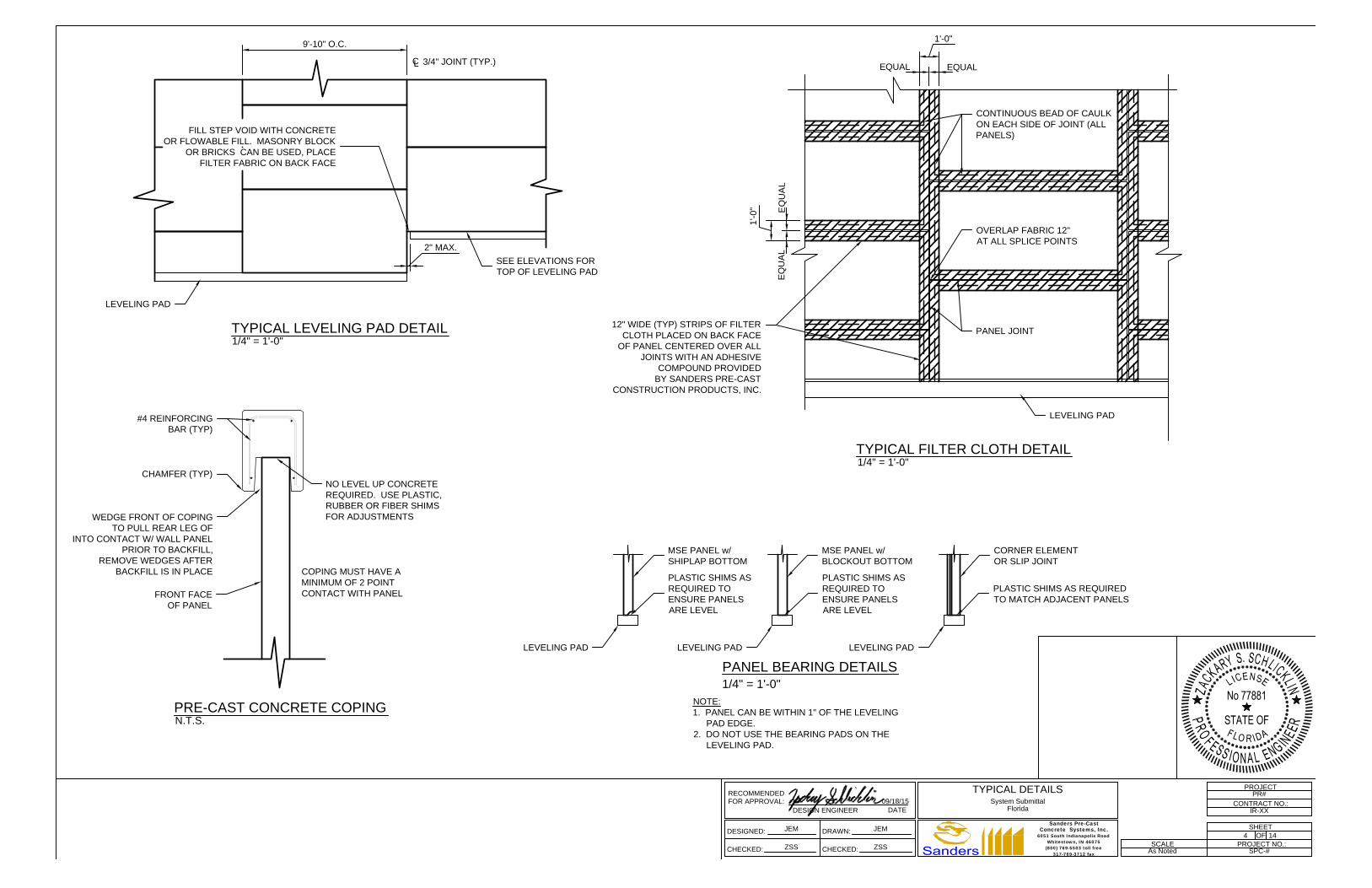
9'-10" O.C.
C
L
3/4" JOINT (TYP.)
TYPICAL LEVELING PAD DETAIL
1/4" = 1'-0"
SEE ELEVATIONS FOR
TOP OF LEVELING PAD
LEVELING PAD
PANEL JOINT
1'-0"
EQUALEQUAL
1'-0
"
EQ
UA
LE
QU
AL
12" WIDE (TYP) STRIPS OF FILTER
CLOTH PLACED ON BACK FACE
OF PANEL CENTERED OVER ALL
JOINTS WITH AN ADHESIVE
COMPOUND PROVIDED
BY SANDERS PRE-CAST
CONSTRUCTION PRODUCTS, INC.
TYPICAL FILTER CLOTH DETAIL
1/4" = 1'-0"
PRE-CAST CONCRETE COPING
N.T.S.
FRONT FACE
OF PANEL
CHAMFER (TYP)
#4 REINFORCING
BAR (TYP)
LEVELING PAD
PANEL BEARING DETAILS
1/4" = 1'-0"
LEVELING PAD
MSE PANEL w/
SHIPLAP BOTTOM
LEVELING PAD
MSE PANEL w/
BLOCKOUT BOTTOM
NO LEVEL UP CONCRETE
REQUIRED. USE PLASTIC,
RUBBER OR FIBER SHIMS
FOR ADJUSTMENTS
LEVELING PAD
PLASTIC SHIMS AS REQUIRED
TO MATCH ADJACENT PANELS
CORNER ELEMENT
OR SLIP JOINT
PLASTIC SHIMS AS
REQUIRED TO
ENSURE PANELS
ARE LEVEL
PLASTIC SHIMS AS
REQUIRED TO
ENSURE PANELS
ARE LEVEL
COPING MUST HAVE A
MINIMUM OF 2 POINT
CONTACT WITH PANEL
WEDGE FRONT OF COPING
TO PULL REAR LEG OF
INTO CONTACT W/ WALL PANEL
PRIOR TO BACKFILL,
REMOVE WEDGES AFTER
BACKFILL IS IN PLACE
OVERLAP FABRIC 12"
AT ALL SPLICE POINTS
2" MAX.
FILL STEP VOID WITH CONCRETE
OR FLOWABLE FILL. MASONRY BLOCK
OR BRICKS CAN BE USED, PLACE
FILTER FABRIC ON BACK FACE
CONTINUOUS BEAD OF CAULK
ON EACH SIDE OF JOINT (ALL
PANELS)
NOTE:
1. PANEL CAN BE WITHIN 1" OF THE LEVELING
PAD EDGE.
2. DO NOT USE THE BEARING PADS ON THE
LEVELING PAD.
4
FOR APPROVAL:
RECOMMENDED
DESIGN ENGINEERDATE
09/18/15
DESIGNED:
CHECKED:
DRAWN:
CHECKED:
PROJECT NO.:
PROJECT
OF
SHEET
CONTRACT NO.:
SCALE
PR#
IR-XX
4 14
SPC-#As Noted
JEM JEM
ZSS ZSS
TYPICAL DETAILS
System Submittal
Florida
6051 South Indianapolis RoadWhitestown, IN 46075
(800) 769-5503 toll free317-769-3712 fax
Concrete Systems, Inc.Sanders Pre-Cast
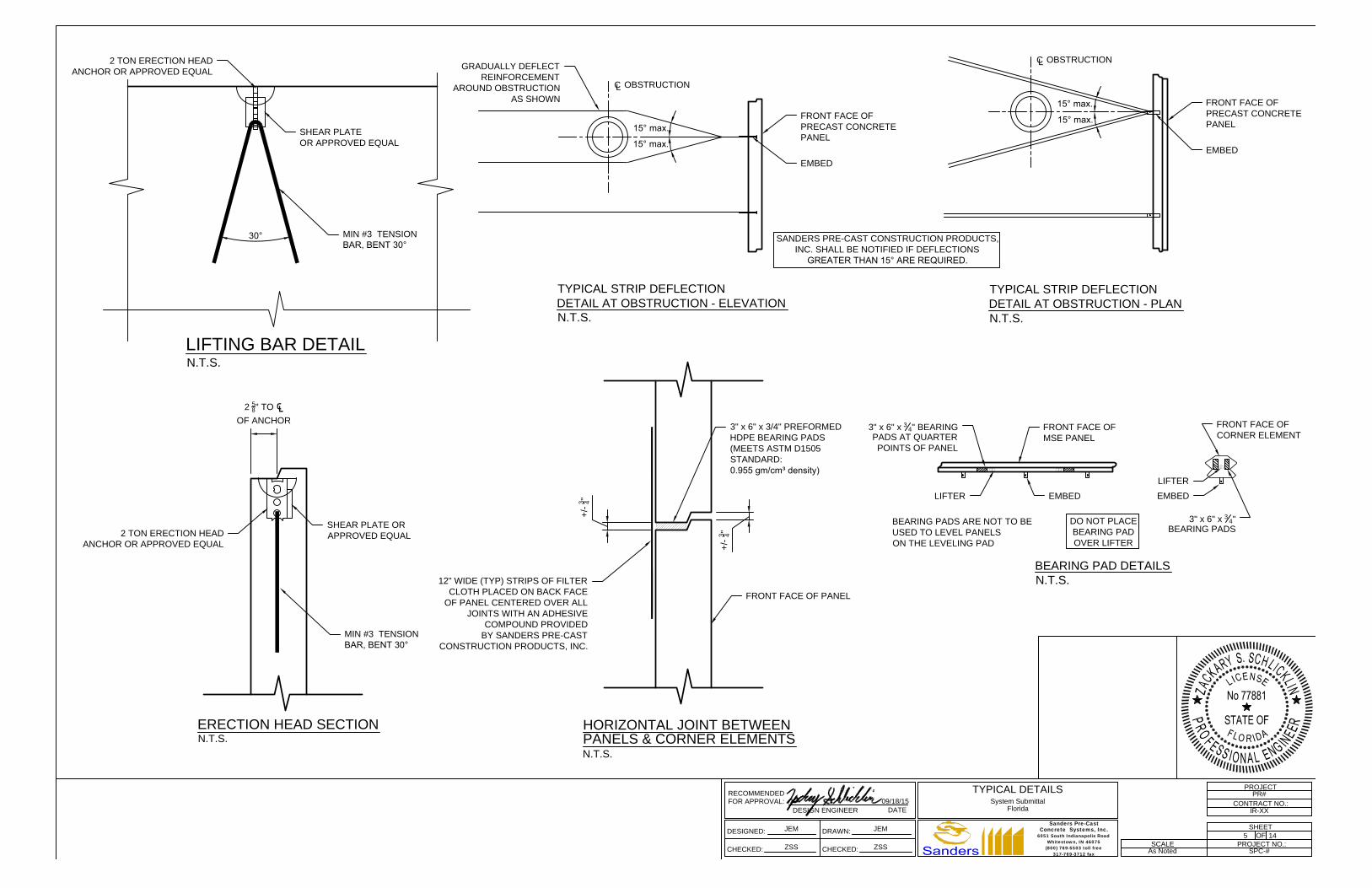
15° max.
15° max.
+/-
3 4
"
+/-
3 4
"
2
5
8
" TO ℄OF ANCHOR
30°
C
L
OBSTRUCTION
GRADUALLY DEFLECT
REINFORCEMENT
AROUND OBSTRUCTION
AS SHOWN
FRONT FACE OF
PRECAST CONCRETE
PANEL
EMBED
N.T.S.
15° max.
15° max.
C
L
OBSTRUCTION
FRONT FACE OF
PRECAST CONCRETE
PANEL
EMBED
TYPICAL STRIP DEFLECTION
DETAIL AT OBSTRUCTION - ELEVATION
N.T.S.
TYPICAL STRIP DEFLECTION
DETAIL AT OBSTRUCTION - PLAN
SHEAR PLATE OR
APPROVED EQUAL
MIN #3 TENSION
BAR, BENT 30°
2 TON ERECTION HEAD
ANCHOR OR APPROVED EQUAL
ERECTION HEAD SECTION
N.T.S.
LIFTING BAR DETAIL
N.T.S.
FRONT FACE OF PANEL
3" x 6" x 3/4" PREFORMED
HDPE BEARING PADS
(MEETS ASTM D1505
STANDARD:
0.955 gm/cm³ density)
HORIZONTAL JOINT BETWEEN
N.T.S.
12" WIDE (TYP) STRIPS OF FILTER
CLOTH PLACED ON BACK FACE
OF PANEL CENTERED OVER ALL
JOINTS WITH AN ADHESIVE
COMPOUND PROVIDED
BY SANDERS PRE-CAST
CONSTRUCTION PRODUCTS, INC.
SANDERS PRE-CAST CONSTRUCTION PRODUCTS,
INC. SHALL BE NOTIFIED IF DEFLECTIONS
GREATER THAN 15° ARE REQUIRED.
PANELS & CORNER ELEMENTS
SHEAR PLATE
OR APPROVED EQUAL
2 TON ERECTION HEAD
ANCHOR OR APPROVED EQUAL
MIN #3 TENSION
BAR, BENT 30°
FRONT FACE OF
MSE PANEL
EMBED
N.T.S.
BEARING PAD DETAILS
3" x 6" x
3
4
" BEARING
PADS AT QUARTER
POINTS OF PANEL
EMBED
FRONT FACE OF
CORNER ELEMENT
3" x 6" x
3
4
"
BEARING PADS
BEARING PADS ARE NOT TO BE
USED TO LEVEL PANELS
ON THE LEVELING PAD
DO NOT PLACE
BEARING PAD
OVER LIFTER
LIFTER
LIFTER
5
FOR APPROVAL:
RECOMMENDED
DESIGN ENGINEERDATE
09/18/15
DESIGNED:
CHECKED:
DRAWN:
CHECKED:
PROJECT NO.:
PROJECT
OF
SHEET
CONTRACT NO.:
SCALE
PR#
IR-XX
5 14
SPC-#As Noted
JEM JEM
ZSS ZSS
TYPICAL DETAILS
System Submittal
Florida
6051 South Indianapolis RoadWhitestown, IN 46075
(800) 769-5503 toll free317-769-3712 fax
Concrete Systems, Inc.Sanders Pre-Cast
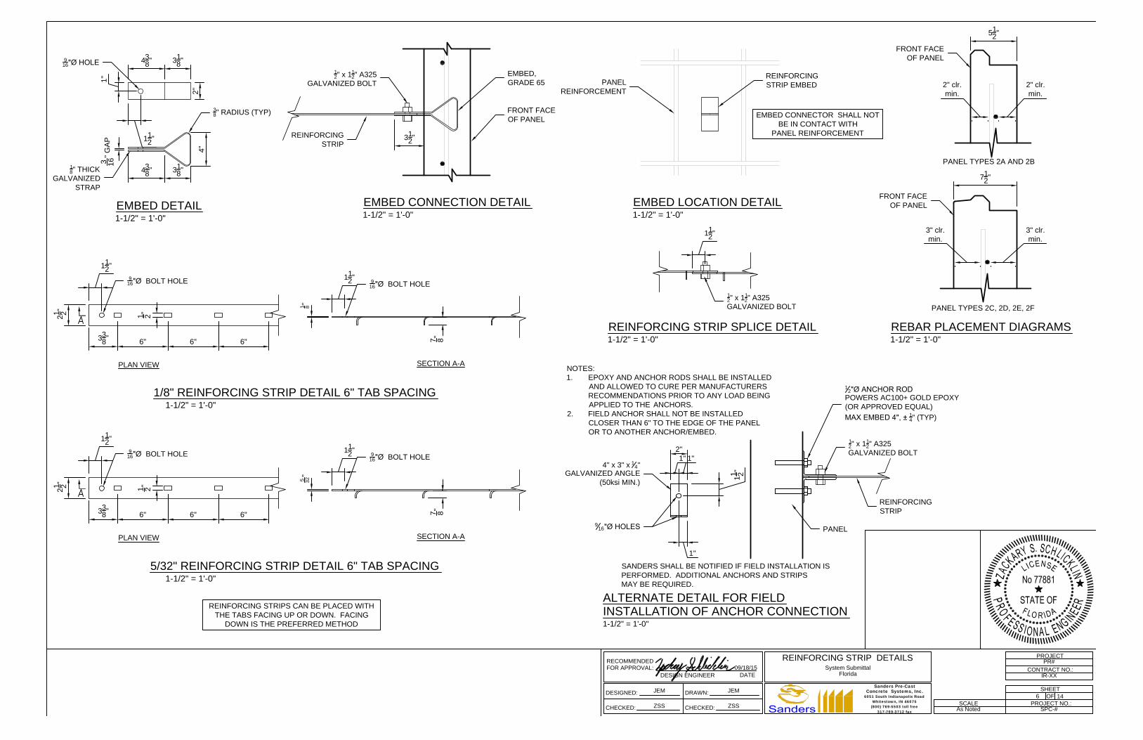
3
1
8
"4
3
8
"
1
1
2
"
1"
2"
4"
3
1
8
"4
3
8
"
3
16
" G
AP
3
8
" RADIUS (TYP)
9
16
"Ø HOLE
EMBED DETAIL
1-1/2" = 1'-0"
FRONT FACE
OF PANEL
EMBED,
GRADE 65
REINFORCING
STRIP
1
2
" x 1
1
2
" A325
GALVANIZED BOLT
EMBED CONNECTION DETAIL
1-1/2" = 1'-0"
1
8
" THICK
GALVANIZED
STRAP
3
1
2
"
REINFORCING STRIPS CAN BE PLACED WITH
THE TABS FACING UP OR DOWN. FACING
DOWN IS THE PREFERRED METHOD
REINFORCING STRIP SPLICE DETAIL
1-1/2" = 1'-0"
1
2
" x 1
1
2
" A325
GALVANIZED BOLT
1
1
2
"
ALTERNATE DETAIL FOR FIELD
REINFORCING
STRIP
1
2
" x 1
1
2
" A325
GALVANIZED BOLT
2"
1"1"
1
1 2
"
1"
4" x 3" x
1
4
"
GALVANIZED ANGLE
(50ksi MIN.)
1-1/2" = 1'-0"
9
16
"Ø HOLES
PANEL
1
2
"Ø ANCHOR ROD
POWERS AC100+ GOLD EPOXY
(OR APPROVED EQUAL)
MAX EMBED 4", ±
1
4
" (TYP)
NOTES:
1. EPOXY AND ANCHOR RODS SHALL BE INSTALLED
AND ALLOWED TO CURE PER MANUFACTURERS
RECOMMENDATIONS PRIOR TO ANY LOAD BEING
APPLIED TO THE ANCHORS.
2. FIELD ANCHOR SHALL NOT BE INSTALLED
CLOSER THAN 6" TO THE EDGE OF THE PANEL
OR TO ANOTHER ANCHOR/EMBED.
INSTALLATION OF ANCHOR CONNECTION
SANDERS SHALL BE NOTIFIED IF FIELD INSTALLATION IS
PERFORMED. ADDITIONAL ANCHORS AND STRIPS
MAY BE REQUIRED.
PLAN VIEW
2
1 2
"
3
3
8
"
6"
1 2
"
9
16
"Ø BOLT HOLE
6"
1
1
2
"
SECTION A-A
1
1
2
"
1
8
"
9
16
"Ø BOLT HOLE
7 8
"
1/8" REINFORCING STRIP DETAIL 6" TAB SPACING
1-1/2" = 1'-0"
PLAN VIEW
2
1 2
"
3
3
8
"
6"
1 2
"
9
16
"Ø BOLT HOLE
6"
1
1
2
"
SECTION A-A
1
1
2
"
5
32
"
9
16
"Ø BOLT HOLE
7 8
"
5/32" REINFORCING STRIP DETAIL 6" TAB SPACING
1-1/2" = 1'-0"
6"
6"
EMBED LOCATION DETAIL
1-1/2" = 1'-0"
PANEL
REINFORCEMENT
REINFORCING
STRIP EMBED
EMBED CONNECTOR SHALL NOT
BE IN CONTACT WITH
PANEL REINFORCEMENT
REBAR PLACEMENT DIAGRAMS
1-1/2" = 1'-0"
5
1
2
"
2" clr.
min.
2" clr.
min.
7
1
2
"
3" clr.
min.
3" clr.
min.
PANEL TYPES 2A AND 2B
PANEL TYPES 2C, 2D, 2E, 2F
FRONT FACE
OF PANEL
FRONT FACE
OF PANEL
6
FOR APPROVAL:
RECOMMENDED
DESIGN ENGINEERDATE
09/18/15
DESIGNED:
CHECKED:
DRAWN:
CHECKED:
PROJECT NO.:
PROJECT
OF
SHEET
CONTRACT NO.:
SCALE
PR#
IR-XX
6 14
SPC-#As Noted
JEM JEM
ZSS ZSS
REINFORCING STRIP DETAILS
System Submittal
Florida
6051 South Indianapolis RoadWhitestown, IN 46075
(800) 769-5503 toll free317-769-3712 fax
Concrete Systems, Inc.Sanders Pre-Cast
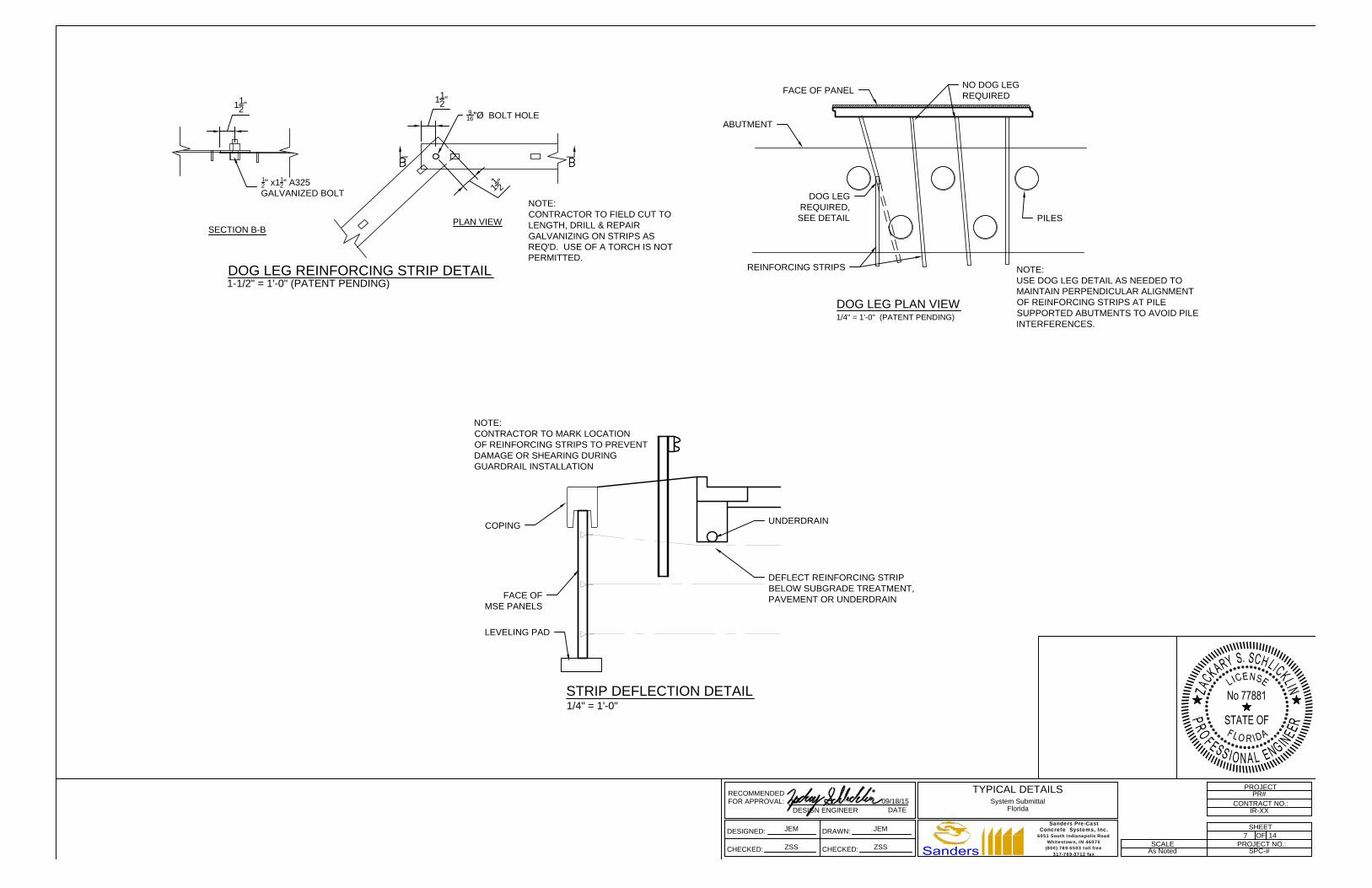
9
16
"Ø BOLT HOLE
1
2
" x1
1
2
" A325
GALVANIZED BOLT
1
1
2
"
SECTION B-B
PLAN VIEW
1
1
2
"
1
1
2
"
NOTE:
CONTRACTOR TO FIELD CUT TO
LENGTH, DRILL & REPAIR
GALVANIZING ON STRIPS AS
REQ'D. USE OF A TORCH IS NOT
PERMITTED.
DOG LEG REINFORCING STRIP DETAIL
1-1/2" = 1'-0" (PATENT PENDING)
FACE OF PANEL
ABUTMENT
PILES
DOG LEG
REQUIRED,
SEE DETAIL
REINFORCING STRIPS
DOG LEG PLAN VIEW
1/4" = 1'-0" (PATENT PENDING)
NOTE:
USE DOG LEG DETAIL AS NEEDED TO
MAINTAIN PERPENDICULAR ALIGNMENT
OF REINFORCING STRIPS AT PILE
SUPPORTED ABUTMENTS TO AVOID PILE
INTERFERENCES.
NO DOG LEG
REQUIRED
UNDERDRAIN
COPING
FACE OF
MSE PANELS
LEVELING PAD
DEFLECT REINFORCING STRIP
BELOW SUBGRADE TREATMENT,
PAVEMENT OR UNDERDRAIN
NOTE:
CONTRACTOR TO MARK LOCATION
OF REINFORCING STRIPS TO PREVENT
DAMAGE OR SHEARING DURING
GUARDRAIL INSTALLATION
STRIP DEFLECTION DETAIL
1/4" = 1'-0"
FOR APPROVAL:
RECOMMENDED
DESIGN ENGINEERDATE
09/18/15
DESIGNED:
CHECKED:
DRAWN:
CHECKED:
PROJECT NO.:
PROJECT
OF
SHEET
CONTRACT NO.:
SCALE
PR#
IR-XX
714
SPC-#As Noted
JEM JEM
ZSS ZSS
TYPICAL DETAILS
System Submittal
Florida
6051 South Indianapolis RoadWhitestown, IN 46075
(800) 769-5503 toll free317-769-3712 fax
Concrete Systems, Inc.Sanders Pre-Cast
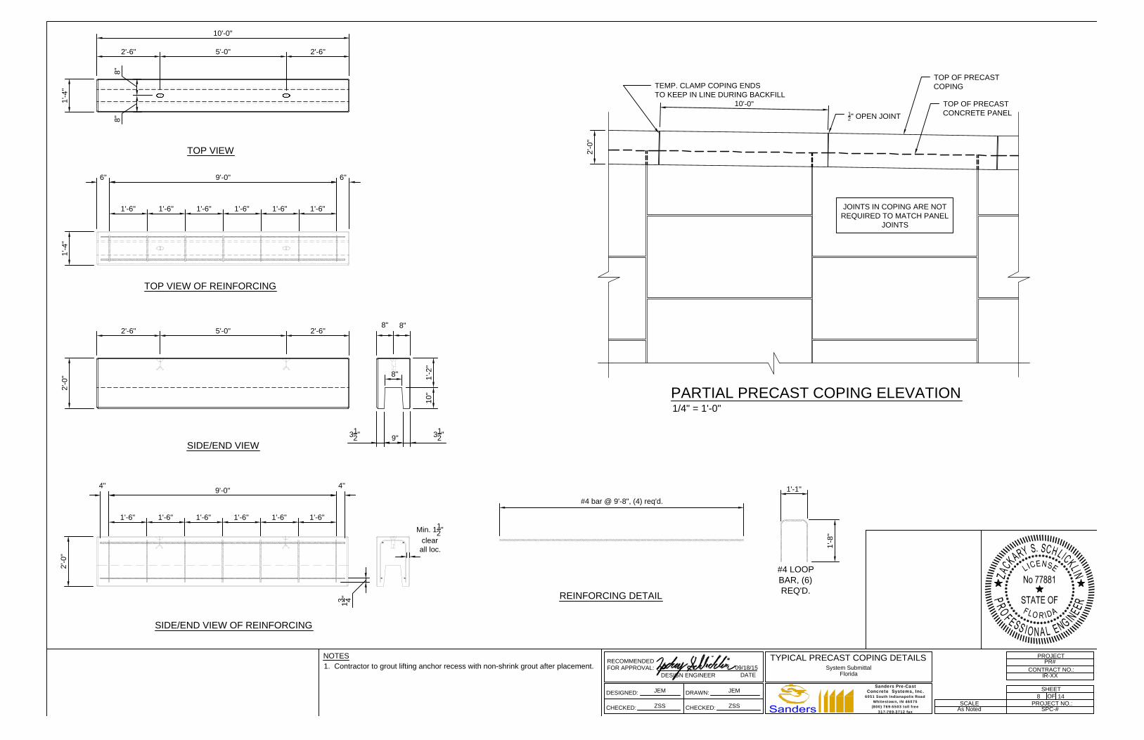
10'-0"
2'-6" 5'-0" 2'-6"
8"
8"
1'-4
"
2'-6" 5'-0" 2'-6"
2'-0
"1
'-4
"
2'-0
"
8"8"
Min. 1
1
2
"
clear
all loc.
#4 bar @ 9'-8", (4) req'd.
1'-1"
1'-8
"
10
"1
'-2
"
8"
3
1
2
"
9"
3
1
2
"
1
3 4
"
#4 LOOP
BAR, (6)
REQ'D.
TOP VIEW
TOP VIEW OF REINFORCING
SIDE/END VIEW
SIDE/END VIEW OF REINFORCING
REINFORCING DETAIL
6" 9'-0" 6"
1'-6" 1'-6" 1'-6" 1'-6" 1'-6"
4"
9'-0"
4"
1'-6" 1'-6" 1'-6" 1'-6" 1'-6"
1'-6"
1'-6"
10'-0"
1
2
" OPEN JOINT
TOP OF PRECAST
COPING
TOP OF PRECAST
CONCRETE PANEL
2'-0
"
PARTIAL PRECAST COPING ELEVATION
1/4" = 1'-0"
JOINTS IN COPING ARE NOT
REQUIRED TO MATCH PANEL
JOINTS
TEMP. CLAMP COPING ENDS
TO KEEP IN LINE DURING BACKFILL
FOR APPROVAL:
RECOMMENDED
DESIGN ENGINEERDATE
09/18/15
NOTES
1. Contractor to grout lifting anchor recess with non-shrink grout after placement.
DESIGNED:
CHECKED:
DRAWN:
CHECKED:
PROJECT NO.:
PROJECT
OF
SHEET
CONTRACT NO.:
SCALE
PR#
IR-XX
8 14
SPC-#As Noted
JEM JEM
ZSS ZSS
TYPICAL PRECAST COPING DETAILS
System Submittal
Florida
6051 South Indianapolis RoadWhitestown, IN 46075
(800) 769-5503 toll free317-769-3712 fax
Concrete Systems, Inc.Sanders Pre-Cast

TROWEL CONCRETE SMOOTH
AGAINST FACE OF WALL
PANEL AROUND PIPE
WRAP AND SECURE FILTER CLOTH
AROUND PIPE OVER JOINT PRIOR
TO BACKFILLING BEHIND WALL
FORM CONCRETE AROUND PIPE
OVER EXP. JOINT MAT'L AS SHOWN.
ALLOW CONCRETE TO SET PRIOR
TO BACKFILLING BEHIND WALL
1" THICK x 12" WIDE EXPANSION
JOINT MATERIAL, BY OTHERS
4" M
IN
.4
" M
IN
.
1
1
1
1
5
1
2
"
PIPE PENETRATION AT WALL FACE DETAIL
1/2" = 1'-0"
FRONT FACE
OF WALL PANELS
1
2
"Ø ANCHOR BOLT
HILTI KB3
(OR APPROVED EQUAL)
MAXIMUM EMBED 4" ±
1
4
"
9
16
"Ø HOLE
2'-0"
1
1
2
"
5 1/2"
MIN.
2'-6
" T
YP
IC
AL
5
1 2
"
MIN
.
1
4
" x 2 "x 2'-0"
GALVANIZED
PLATE
EDGE OF
PANEL
DETAIL FOR PANEL JOINT AT OBSTRUCTION
N.T.S.
1
2
"Ø ANCHOR BOLT
HILTI KB3
(OR APPROVED EQUAL)
MAXIMUM EMBED 4" ±
1
4
"
1
4
" x 2" x 2'-0"
GALVANIZED
PLATE
SOIL REINFORCING
SKEWED TO AVOID
OBSTRUCTION
EXAMPLE PANEL JOINT AT OBSTRUCTION
1/4"=1'-0"
FOR APPROVAL:
RECOMMENDED
DESIGN ENGINEERDATE
09/18/15
DESIGNED:
CHECKED:
DRAWN:
CHECKED:
PROJECT NO.:
PROJECT
OF
SHEET
CONTRACT NO.:
SCALE
PR#
IR-XX
9 14
SPC-#As Noted
JEM JEM
ZSS ZSS
CORNER DETAILS
System Submittal
Florida
6051 South Indianapolis RoadWhitestown, IN 46075
(800) 769-5503 toll free317-769-3712 fax
Concrete Systems, Inc.Sanders Pre-Cast
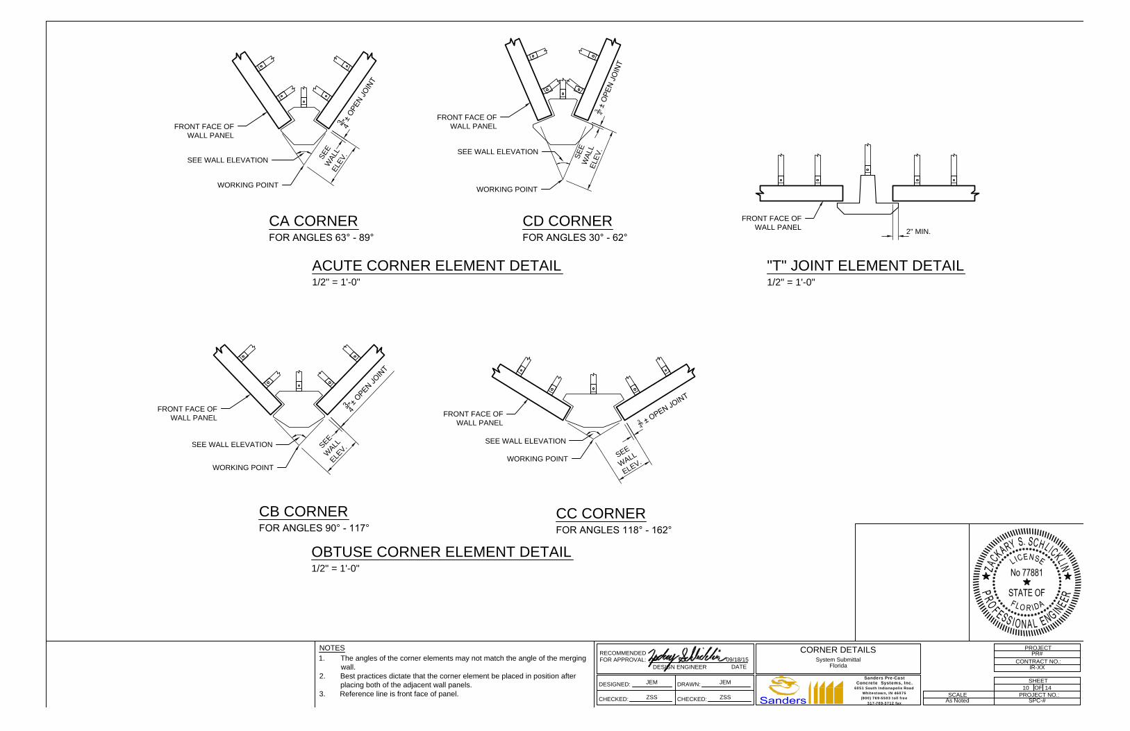
ACUTE CORNER ELEMENT DETAIL
1/2" = 1'-0"
FRONT FACE OF
WALL PANEL
FRONT FACE OF
WALL PANEL
S
E
EW
A
L
L
E
L
E
V
.
WORKING POINT
3
4"
±
O
P
E
N
J
O
I
N
T
WORKING POINT
S
E
E
W
A
L
L
E
L
E
V
.
3
4
"
±
O
P
E
N
J
O
I
N
T
SEE WALL ELEVATION
SEE WALL ELEVATION
CA CORNER CD CORNER
FOR ANGLES 63° - 89° FOR ANGLES 30° - 62°
CB CORNER
CC CORNER
FRONT FACE OF
WALL PANEL
FRONT FACE OF
WALL PANEL
S
E
E
W
A
L
L
E
L
E
V
.3
4"
±
O
P
E
N
J
O
I
N
T
WORKING POINT
WORKING POINT
S
E
E
W
A
L
L
E
L
E
V
.
3
4
"
±
O
P
E
N
J
O
I
N
T
SEE WALL ELEVATION
SEE WALL ELEVATION
OBTUSE CORNER ELEMENT DETAIL
1/2" = 1'-0"
FOR ANGLES 90° - 117°
FOR ANGLES 118° - 162°
"T" JOINT ELEMENT DETAIL
1/2" = 1'-0"
FRONT FACE OF
WALL PANEL
2" MIN.
FOR APPROVAL:
RECOMMENDED
DESIGN ENGINEERDATE
09/18/15
DESIGNED:
CHECKED:
DRAWN:
CHECKED:
PROJECT NO.:
PROJECT
OF
SHEET
CONTRACT NO.:
SCALE
PR#
IR-XX
10 14
SPC-#As Noted
JEM JEM
ZSS ZSS
CORNER DETAILS
System Submittal
Florida
NOTES
1. The angles of the corner elements may not match the angle of the merging
wall.
2. Best practices dictate that the corner element be placed in position after
placing both of the adjacent wall panels.
3. Reference line is front face of panel.
6051 South Indianapolis RoadWhitestown, IN 46075
(800) 769-5503 toll free317-769-3712 fax
Concrete Systems, Inc.Sanders Pre-Cast

PRECAST CORNER
ELEMENT
WORK POINT
STEEL PILE
W/ SLEEVE
ABUTMENT
REINFORCING STRIPS
SHALL BE FIELD CUT
AND DRILLED PER
PANEL TO PANEL
STRIP DETAIL
STRIPS SKEWED TO
AVOID PILE SLEEVE
ABUTMENT
EXAMPLE OF ACUTE CORNER AND SKEWED SOIL REINFORCING
1/4"=1'-0"
REINFORCING
STRIP
PANEL-TO-PANEL STRIP DETAIL
1-1/2" = 1'-0"
FRONT FACE
OF PANEL
EMBED
1
2
" x 1
1
2
" A325
GALVANIZED BOLT
NOTE:
CONTRACTOR TO FIELD CUT TO LENGTH,
DRILL & REPAIR GALVANIZING ON STRIPS
AS REQ'D. AT PANEL TO PANEL WALL
CONDITION. USE OF A TORCH IS NOT
PERMITTED.
FOR APPROVAL:
RECOMMENDED
DESIGN ENGINEERDATE
DESIGNED:
CHECKED:
DRAWN:
CHECKED:
PROJECT NO.:
PROJECT
OF
SHEET
CONTRACT NO.:
SCALE
PR#
IR-XX
11 14
SPC-#As Noted
JEM JEM
ZSS ZSS
TYPICAL DETAILS
System Submittal
Florida
09/18/15
6051 South Indianapolis RoadWhitestown, IN 46075
(800) 769-5503 toll free317-769-3712 fax
Concrete Systems, Inc.Sanders Pre-Cast
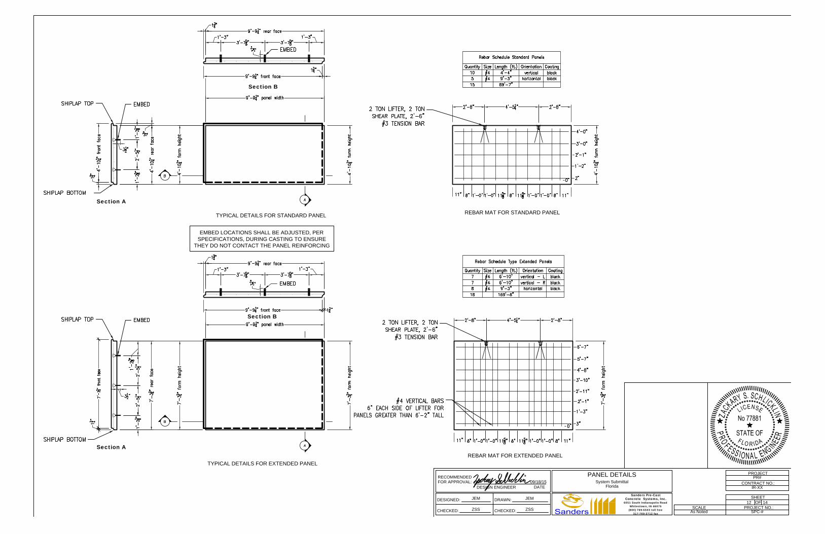
EMBED LOCATIONS SHALL BE ADJUSTED, PER
SPECIFICATIONS, DURING CASTING TO ENSURE
THEY DO NOT CONTACT THE PANEL REINFORCING
Section B
Section A
TYPICAL DETAILS FOR STANDARD PANEL
Section A
Section B
TYPICAL DETAILS FOR EXTENDED PANEL
REBAR MAT FOR STANDARD PANEL
REBAR MAT FOR EXTENDED PANEL
FOR APPROVAL:
RECOMMENDED
DESIGN ENGINEERDATE
DESIGNED:
CHECKED:
DRAWN:
CHECKED:
PROJECT NO.:
PROJECT
OF
SHEET
CONTRACT NO.:
SCALE
PR#
IR-XX
12 14
SPC-#As Noted
JEM JEM
ZSS ZSS
PANEL DETAILS
System Submittal
Florida
09/18/15
6051 South Indianapolis RoadWhitestown, IN 46075
(800) 769-5503 toll free317-769-3712 fax
Concrete Systems, Inc.Sanders Pre-Cast

S7T S7S5
9'-9
1
4
" panel width
2'-9
1
8
" 2'-9
1
8
"
4'-3"
1'-3"
3'-7
5
8
" 3'-7
5
8
"
1'-3"
2'-5
1 2
"
4'-1
0
1 4
" fo
rm
h
eig
ht
4'-1
0
1 4
" fo
rm
h
eig
ht
1'-2
3 8
"
1'-2
3 8
"
2'-5
1 2
"
1'-2
3 8
"1
'-2
3 8
"
9'-9
1
4
" panel width
1'-3" 1'-3"
3'-7
5
8
" 3'-7
5
8
"
1'-3"
2'-8
1
8
"
1'-11"
2'-8
1
8
"
1'-3"
2'-5
1 2
"
4'-1
0
1 4
" fo
rm
h
eig
ht
4'-1
0
1 4
" fo
rm
h
eig
ht
1'-2
3 8
"1
'-2
3 8
"
2'-5
1 2
"
1'-2
3 8
"1
'-2
3 8
"
9'-9
1
4
" panel width
1'-3" 1'-3"
2'-8
1
8
"
1'-11"
2'-8
1
8
"
1'-3"
3'-7
5
8
" 3'-7
5
8
"
1'-3"
2'-5
1 2
"
4'-1
0
1 4
" fo
rm
h
eig
ht
4'-1
0
1 4
" fo
rm
h
eig
ht
1'-2
3 8
"
1'-2
3 8
"
2'-5
1 2
"
1'-2
3 8
"1
'-2
3 8
"
7'-3
3 4
" fo
rm
h
eig
ht
3'-7
5
8
"3'-7
5
8
"
1'-3" 1'-3"
9'-9
1
4
" panel width
2'-5
3 8
"
1'-2
3 8
"
2'-5
1 2
"
2'-5
1 2
"
2'-5
3 8
"
1'-2
1 2
"
1'-2
3 8
"1
'-2
1 2
"
2'-9
1
8
" 2'-9
1
8
"
4'-3"
1'-3" 1'-3"
1'-6
1
4
" 1'-6
1
4
"1'-4
5
8
" 1'-5
1
2
" 1'-4
5
8
"
7'-3
3 4
" fo
rm
h
eig
ht
7'-3
3 4
" fo
rm
h
eig
ht
9'-9
1
4
" panel width
3'-7
5
8
" 3'-7
5
8
"
1'-3" 1'-3"
2'-5
3 8
"
1'-2
3 8
"
2'-5
1 2
"
2'-5
1 2
"
2'-5
3 8
"
1'-2
1 2
"
1'-2
3 8
"1
'-2
1 2
"
2'-9
1
8
" 2'-9
1
8
"
4'-3"
1'-3" 1'-3"
2'-8
1
8
"
1'-11"
2'-8
1
8
"
9'-9
1
4
" panel width
2'-5
1 2
"
1'-2
3 8
"
2'-5
1 2
"
1'-2
3 8
"
7'-3
3 4
" fo
rm
h
eig
ht
7'-3
3 4
" fo
rm
h
eig
ht
1'-3"
1'-6
1
8
" 2'-1
1
2
" 2'-1
1
2
" 1'-6
1
8
"
1'-3"
2'-8
1
8
"
1'-11"
2'-8
1
8
"
1'-3" 1'-3"
1'-6
5
8
"
1'-1
1
2
"
11
1
2
" 11
1
2
"
1'-6
5
8
"
1'-1
1
2
"
2'-5
3 8
"
2'-5
3 8
"
1'-2
1 2
"
1'-2
1 2
"
E11T E9T E16
7'-3
3 4
" fo
rm
h
eig
ht
FOR APPROVAL:
RECOMMENDED
DESIGN ENGINEERDATE
DESIGNED:
CHECKED:
DRAWN:
CHECKED:
PROJECT NO.:
PROJECT
OF
SHEET
CONTRACT NO.:
SCALE
13
IR-XX
13 14
SPC-#As Noted
JEM JEM
ZSS ZSS
STANDARD PANEL EXAMPLES
System Submittal
Florida
09/18/15
6051 South Indianapolis RoadWhitestown, IN 46075
(800) 769-5503 toll free317-769-3712 fax
Concrete Systems, Inc.Sanders Pre-Cast
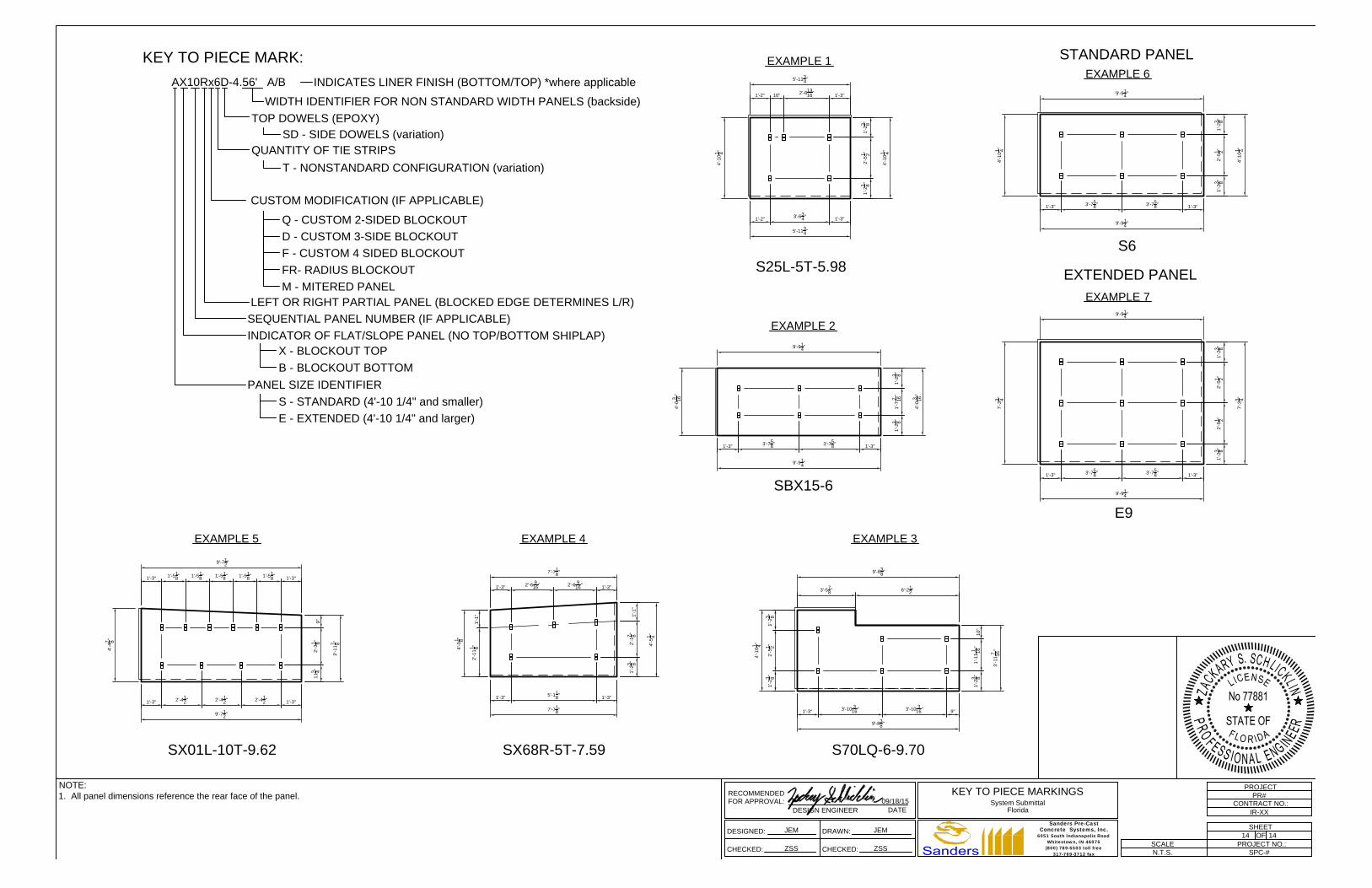
KEY TO PIECE MARK:
AX10Rx6D-4.56' A/B
TOP DOWELS (EPOXY)
QUANTITY OF TIE STRIPS
LEFT OR RIGHT PARTIAL PANEL (BLOCKED EDGE DETERMINES L/R)
SEQUENTIAL PANEL NUMBER (IF APPLICABLE)
INDICATOR OF FLAT/SLOPE PANEL (NO TOP/BOTTOM SHIPLAP)
PANEL SIZE IDENTIFIER
WIDTH IDENTIFIER FOR NON STANDARD WIDTH PANELS (backside)
S - STANDARD (4'-10 1/4" and smaller)
E - EXTENDED (4'-10 1/4" and larger)
CUSTOM MODIFICATION (IF APPLICABLE)
Q - CUSTOM 2-SIDED BLOCKOUT
D - CUSTOM 3-SIDE BLOCKOUT
F - CUSTOM 4 SIDED BLOCKOUT
FR- RADIUS BLOCKOUT
M - MITERED PANEL
SD - SIDE DOWELS (variation)
T - NONSTANDARD CONFIGURATION (variation)
INDICATES LINER FINISH (BOTTOM/TOP) *where applicable
X - BLOCKOUT TOP
B - BLOCKOUT BOTTOM
EXAMPLE 5
9'-7
1
2
"
3'-11
7 8
"
9'-7
1
2
"
4'-4
7 8
"
11
3 4
"2'-3
1 8
"
9"
1'-3"
2'-4
1
2
" 2'-4
1
2
"
1'-3"
SX01L-10T-9.62
1'-3" 1'-3"
2'-4
1
2
"
1'-5
1
8
" 1'-5
1
8
" 1'-5
1
8
" 1'-5
1
8
" 1'-5
1
8
"
EXAMPLE 4
SX68R-5T-7.59
7'-7
1
8
"
4'-5
1 4
"
7'-7
1
8
"
4'-0
1
8
"
1'-2
3 8
"2'-1
7 8
"
1'-1"
1'-3"
5'-1
1
8
"
1'-3"
1'-3"
2'-6
9
16
" 2'-6
9
16
"
1'-3"
1'-1"
2'-11
1 8
"
EXAMPLE 3
EXAMPLE 2
EXAMPLE 1
5'-11
3
4
"
4'-10
1 4
"
5'-11
3
4
"
4'-10
1 4
"
1'-2
3 8
"2'-5
1 2
"1'-2
3 8
"
1'-2"
3'-6
3
4
"
1'-3"
S25L-5T-5.98
1'-2" 10"
2'-8
13
16
"
1'-3"
SBX15-6
9'-8
3
8
"
3'-11
7
16
"
9'-8
3
8
"
4'-10
1 4
"
1'-2
3 8
"1'-11
1
16
"
10"
1'-3"
3'-10
3
16
" 3'-10
3
16
"
9"
S70LQ-6-9.70
3'-5
7
8
" 6'-2
1
2
"
1'-2
3 8
"2'-5
1 2
"1'-2
3 8
"
9'-9
1
4
"
4'-10
1 4
"
4'-10
1 4
"
9'-9
1
4
"
7'-3
3 4
"
7'-3
3 4
"
1'-3" 1'-3"
1'-2
3 8
"2'-5
1 2
"1'-2
3 8
"
3'-7
5
8
" 3'-7
5
8
"
S6
EXAMPLE 6
E9
EXTENDED PANEL
2'-5
1 2
"1'-2
3 8
"2'-5
1 2
"1'-2
3 8
"
1'-3" 1'-3"
3'-7
5
8
" 3'-7
5
8
"
EXAMPLE 7
STANDARD PANEL
9'-9
1
4
"
9'-9
1
4
"
9'-9
1
4
"
4'-0
3
16
"
4'-0
3
16
"
1'-3" 1'-3"
1'-2
3 8
"1'-7
7
16
"1'-2
3 8
"
3'-7
5
8
" 3'-7
5
8
"
9'-9
1
4
"
FOR APPROVAL:
RECOMMENDED
DESIGN ENGINEERDATE
DESIGNED:
CHECKED:
DRAWN:
CHECKED:
PROJECT NO.:
PROJECT
OF
SHEET
CONTRACT NO.:
SCALE
PR#
IR-XX
14 14
SPC-#N.T.S.
JEM JEM
ZSS ZSS
KEY TO PIECE MARKINGS
System Submittal
Florida
09/18/15
NOTE:
1. All panel dimensions reference the rear face of the panel.
6051 South Indianapolis RoadWhitestown, IN 46075
(800) 769-5503 toll free317-769-3712 fax
Concrete Systems, Inc.Sanders Pre-Cast