sand casting - · pdf filesand casting . assignment 2 • create a two patterns that...
TRANSCRIPT

Sand Casting

Assignment 2
• Create a two patterns that interlock in some way. These will be cast in aluminum using green sand and with the class built crucible furnace.
• Your original patterns need to be made from a relatively hard substance (high density foam, wood or 3D printed pattern are some things I would suggest).
• The patterns can be hand formed, printed or milled. • They may be two-sided, although they will need to have perfect
draft along a straight parting line. • Each team will need to cast at least two sets of patterns (you only
need to make one pair of originals). In the final cast the parts must be interchangeable (some final chasing of the patterns will be allowed – however they should fit without major milling).
• Each pattern should not be larger than x,y,z: 5”x4”x3” and the part line should occur along the xy plane.


Wood Patterns

Foam Patterns

3D printed pattern for sand casting
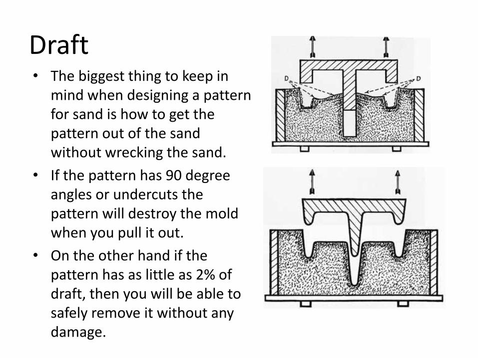
Draft • The biggest thing to keep in
mind when designing a pattern for sand is how to get the pattern out of the sand without wrecking the sand.
• If the pattern has 90 degree angles or undercuts the pattern will destroy the mold when you pull it out.
• On the other hand if the pattern has as little as 2% of draft, then you will be able to safely remove it without any damage.

Draft Illustration

What is aluminum? • Aluminum is the third most abundant
element on the planet (after oxygen and silicon). It is the most abundant metal on earth.
• In spite of this abundance, up until the 1880’s it was valued for its rarity. This is due to the difficulty of extracting the metal.
• Aluminum is rarely found in it natural state. It bonds readily with oxygen and and is usually found in oxides or silicates.
• Aluminum silicate is often used as a stucco in ceramic shell casting.
• Aluminum oxide is extremely tough and has a high melting point (3,600 °F). For this reason it is commonly used in abrasives.
• Until the Hall-Héroult process was developed in the late 1880s, aluminum retained a value higher than gold.
• Napoleon III of France is reputed to have given a banquet where the most honoured guests were given aluminium utensils, while the others made do with gold.

• Although aluminum salts were used in Roman times to dress wounds, the metal was not commonly used until the 1800’s.
• The statue of the Anteros, was made in 1893 and is one of the first statues to be cast in aluminum.
• It was the high value of Aluminum in 1884 that was the deciding factor in creating the 100 ounce capstone of the Washinton Monument. At this point in time, one ounce had the same cost as the daily wage of an average worker on the Monument. This was the largest aluminum casting at the time.
The statue of the Anteros, was made in 1893 and is one of the first statues to be cast in aluminum.

Refining Aluminum • The Hall–Héroult process was invented independently and almost simultaneously in 1886 by the American chemist Charles Martin Hall and the Frenchman Paul Héroult. In 1888, Hall opened the first large-scale aluminium production plant in Pittsburgh. It later became the Alcoa corporation.
• In the Hall–Héroult process alumina, Al2O3, is dissolved in an industrial carbon-lined vat of molten cryolite, Na3AlF6 (sodium hexafluoroaluminate), called a "cell".
• The molten mixture of cryolite, alumina, aluminium fluoride is then electrolyzed by passing a direct electric current through it. The electrochemical reaction causes liquid aluminium metal to be deposited at the cathode as a precipitate, while the oxygen from the alumina combines with carbon from the anode to produce carbon dioxide, CO2.
• The liquid aluminium is taken out with the help of a siphon operating with a vacuum, in order to avoid having to use extremely high temperature valves and pumps. The liquid aluminium then may be transferred in batches or via a continuous hot flow line to a location where it is cast into aluminium ingots.

Properties of Aluminum • Aluminum, refined commonly from bauxite has one of
the best strength vs. weight ratios in the family of metals. . It is easily machined, cast, drawn and extruded.
• Aluminum has about one-third the density and stiffness of steel.
• Aluminium is a good thermal and electrical conductor, having 59% the conductivity of copper, both thermal and electrical.
• One important structural limitation of aluminium alloys is their fatigue strength. Unlike steels, aluminium alloys have no well-defined fatigue limit, meaning that fatigue failure eventually occurs, under even very small cyclic loadings. This implies that engineers must assess these loads and design for a fixed life rather than an infinite life.
• Aluminum is highly corrosion resistant, this is due to the very strong thin layer of aluminum oxide which forms on the surface when exposed to air.
• The strongest aluminum alloys contain copper and are somewhat less resistant to corrosion because of a galvanic reaction.
Bauxite Ore

• The high level of ductility in Aluminum is one of the properties that makes it valuable.
Schematic appearance of round metal bars after tensile testing. (a) Brittle fracture (b) Ductile fracture (c) Completely ductile fracture

• Aluminum is sensitive to heat and unlike other metals will melt without glowing red first. There are no visual signs reveal how close the material is to melting.
• Aluminum alloys, like all structural alloys, also are subject to internal stresses following heating operations such as welding and casting. The problem with aluminum alloys in this regard is their low melting point, which make them more susceptible to distortions from thermally induced stress relief.
• Controlled stress relief can be done during manufacturing by heat-treating the parts in an oven, followed by gradual cooling—in effect annealing the stresses.
Aluminum
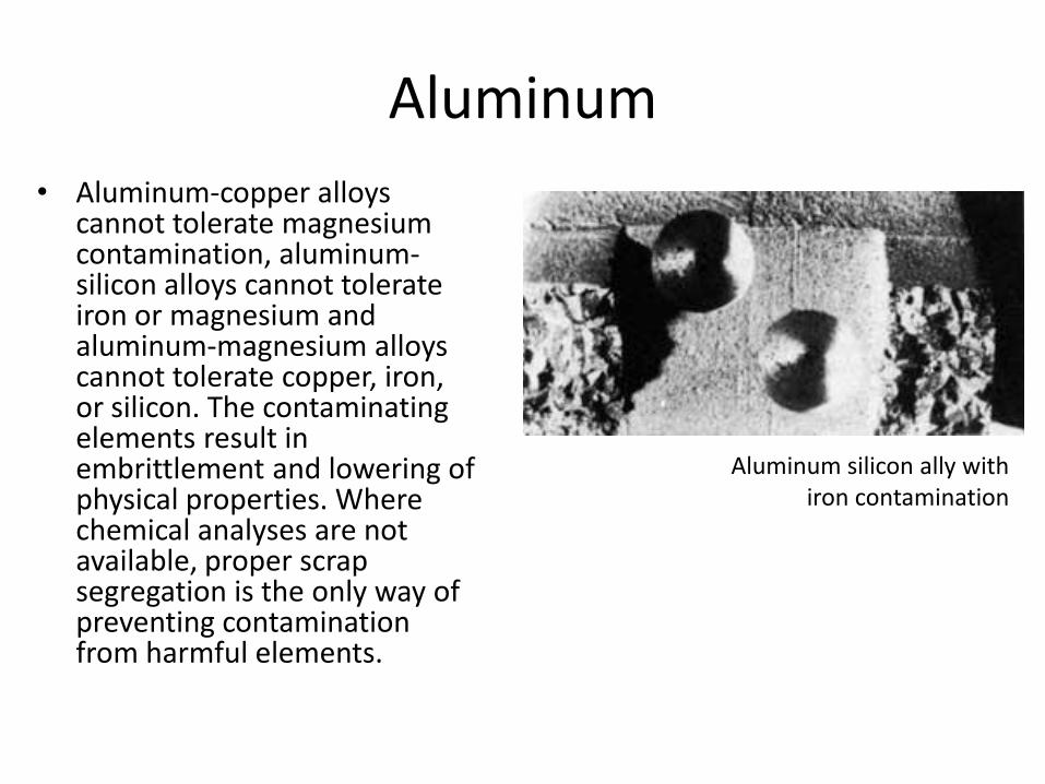
• Aluminum-copper alloys cannot tolerate magnesium contamination, aluminum-silicon alloys cannot tolerate iron or magnesium and aluminum-magnesium alloys cannot tolerate copper, iron, or silicon. The contaminating elements result in embrittlement and lowering of physical properties. Where chemical analyses are not available, proper scrap segregation is the only way of preventing contamination from harmful elements.
Aluminum silicon ally with iron contamination

Casting Aluminum • It is best to use clean ingot and not scrap or
remelt. If you do use remelt, make sure you have at least 60% new metal.
• If you have to use scrap, use engine blocks – this is a reasonably good casting alloy. Soda cans are an alloy designed for extrusion and the thin surface contain a great deal of aluminum oxide.
• Do not over heat the metal! If it is boiling you should actually remove the crucible and allow it to lower to pouring temperature.
• Overheated metal results in gas bubbles, large crystals and lower strength.
• If you “boil” the metal you will also lose trace elements and coat your furnace with metal which can contaminate other pours.
• Melting temperature can range from 1150-1400 degrees Fahrenheit depending on the specific alloy.
What is wrong in this picture?

Gas and Aluminum
• You may need to degas the metal (mostly it is hydrogen in the metal). Specially engineered tablets are best, but chlorine tablets (swimming pool) will work.
• Weld up a stainless steel cup with holes drilled into it onto a long bar. You will also need a tool to remove the tablet – a stainless steel slotted spoon actually works fine.
• When the metal reaches pouring temperature, remove the crucible from the furnace and allow it to cool slightly (the crucible should lose color)
• Then plunge the tablet into the molten metal for 30 seconds and then scoop the tablet from the pot and take it out of the pouring area.
• Skim as normal then pour. • An alternate method is to pump inert
argon gas through a slotted steel pipe for a few seconds. This is the healthier alternative although chlorine does improve the quality of the metal.
The nature of metal as it transforms from liquid to solid
• A casting is made up of many closely packed and joined grains or crystals of metal.
• Within any particular crystal, the atoms are arranged in regular orderly layers, like building blocks.
• There is no orderly arrangement of atoms in molten metal.
• Solidification, therefore, is the formation and growth of crystals, layer by layer, from the melt.
• The size of the crystals is controlled by the time required for the metal to solidify and by its cooling rate in the mold.

Cooling pattern of metal.
• Solidification of a casting is brought about by the cooling effect of the mold.
• Within a few seconds after pouring, a thin layer of metal next to the mold wall is cool enough for solidification to begin.
• At this time, a thin skin or shell of solid metal forms. The shell gradually thickens as more and more metal is cooled, until all the metal has solidified.
• Solidification always starts at the surface and finishes in the center of a section. In other words, solidification follows the direction that the metal is cooled.
Solidification
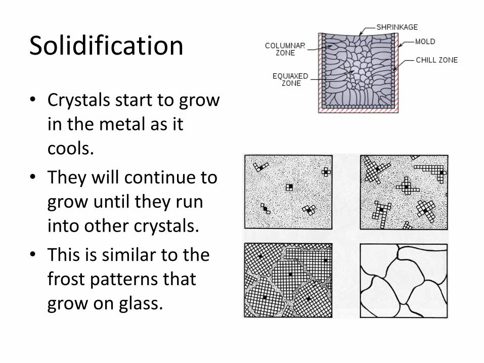
• Crystals start to grow in the metal as it cools.
• They will continue to grow until they run into other crystals.
• This is similar to the frost patterns that grow on glass.

Dendrites • Metals crystallize in tree like patterns
which are called dendrites. • (a) shows the crystal shortly after it
has formed and has started to grow. • (b) the crystal has become elongated
and growth has started in two other directions.
• (c) still further growth is shown by part The original body of the crystal has grown still longer and has become thicker in cross section. Two other sets of arms have started growing near the ends of the longest arms of the crystal.
• (d) even more progressed stage of growth

High magnification of an aluminum casting to show dendrite growth

How the thickness of the casting effects crystal size
Crystal growth in gun metal casting dumped before solidification was complete.
Types of shrinkage
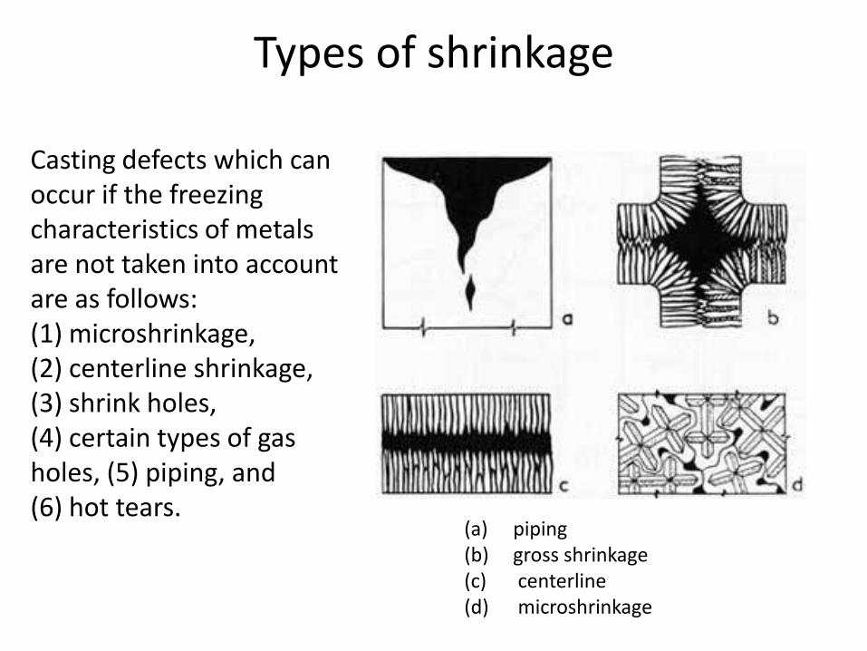
Casting defects which can occur if the freezing characteristics of metals are not taken into account are as follows: (1) microshrinkage, (2) centerline shrinkage, (3) shrink holes, (4) certain types of gas holes, (5) piping, and (6) hot tears.
(a) piping (b) gross shrinkage (c) centerline (d) microshrinkage

Effect of fillets on shrink and crystal growth

Directional Solidification
Design your casting for strength – this includes thoughts about directional solidification, what is the pathway that the material solidifies

Directional solidification
• Directional solidification means that solidification will start in one part of the mold and gradually move in a desired direction; it means that solidification will not start in some area where molten metal is needed to feed the casting.
• An effort is always made by the metal caster to get solidification to progress toward the riser from the point furthermost from the riser.
• Casting design is a determining factor in the control of the direction of solidification, and every effort should be made to apply the principles of good design to reach this objective.
• All sections should be tapered so that they are thickest near the risers.
• Heavy sections should not be located so that feeding must take place through thin sections.

• Thinner sections are going to cool first
• Thicker sections will pull from thinner ones so placement of risers that allow the casting to pull from is important.
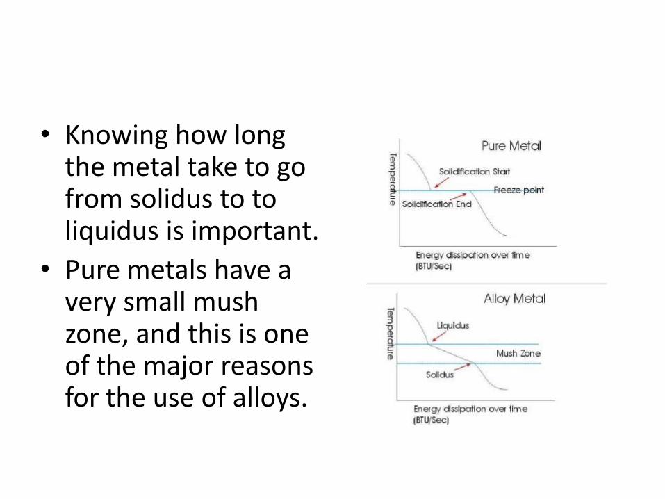
• Knowing how long the metal take to go from solidus to to liquidus is important.
• Pure metals have a very small mush zone, and this is one of the major reasons for the use of alloys.

Wheel designs – taking in account solidification patterns

Cross sections that consider strength and solidification

Hot spots Part of this is considering where hot spots are going to remain and what techniques you are going to use to combat them. Aluminum is one of the hardest metals to deal with in this factor because its liquidus to solidus time is very long.

How does the shape of the pattern effect the flow of the metal?


Pouring temperature
• The pouring temperature and method of pouring determine whether a properly melted heat and a properly made mold will produce a good casting. Aluminum and its alloys should be poured at as low a temperature as possible without causing misruns. For any given alloy, the pouring temperature will determine whether a casting will have a fine grain structure and good properties or a coarse grain structure and lower properties. A high pouring temperature will tend to give a large grain size, and a low pouring temperature will tend to give a small grain size. The pouring temperature will vary between 1,240°F. and 1,400°F., depending on the alloy and section size of the casting. If a casting poured at 1,400° F., misruns, the gating should be revised to allow faster pouring.
• Because aluminum absorbs gases easily, pouring should be done with the lip of the ladle as close as possible to the sprue of the mold. The stream of molten metal should be kept as large as possible (as large a stream as the sprue will handle). A thin stream or trickle of molten metal from a ladle that is held high above the mold will cause a gas pickup and unnecessary agitation of the metal.

Color and
melting points of
a wide variety of
metals

Gas
• Many defects in castings are caused by gases which dissolve in the metal and then are given off during solidification. These defects may range in size and form from microscopic porosity to large blow holes. Because of the large volume that a small weight of gas occupies, very little gas by weight can cause the foundryman a lot of trouble.
• As an example, at room temperature and atmospheric pressure, 0.001 percent by weight of hydrogen in a metal occupies a volume equal to that of the metal, and at 2,000°F., the same amount of hydrogen would occupy a volume equal to four times that of metal.

Porosity
• Pinhole porosity in aluminum castings is caused by poor melting practice. This type of defect is common and shows up as very small gas holes that are scattered through the casting. They may or may not show up on the casting surface.
• Porosity of this nature can be cured only by correct melting practice.
• Melting tools must be clean and dry to prevent any pickup of moisture by the melt.
• Degassing procedures must be used to remove any gases which are dissolved in the melt.

Porosity at surface of metal
• Excessive moisture in the molding sand will cause porosity in aluminum castings.
• This defect can be easily identified because it occurs just below the surface of the casting and on all surfaces.
• The cure for this defect is to use the correct moisture content in the molding sand. This can be done only through proper testing procedures.

With aluminum casting, the goal is generally to make the part both light and strong. This is one of the
reasons the process of designing an aluminum part can be so very complicated.
Use ribs to avoid warpage or to add stiffness. Ribbed construction can often be used to replace a heavier section.

In spite of all of these factors, you should try to keep your pattern as
simple as possible. If it is not possible to create a simple casting, you may
want to consider breaking your design into smaller parts.

Green Sand
• Green sand is not green in color, it is green because only water and clay holds it together as a binder.
• It is the oldest of the sand molding processes.
• The molds are usally two part and built into a flask.

Chosing Sands
• All the following recipe guidelines are based on weight not volume.
• Start with sand, “foundry sand” in particular works nicely because of the structure of the grains. This is usually a silica sand.
• Olivine sand is also frequently used. It is more expensive, but does not have the silicosis hazards of silica
• Selection of grain size is also very important. Generally most foundry sand ranges from 80-200 mesh. Finer sand yields a finer casting but have the potential to trap gas. Coarser sands result in the reverse.
• In resin bonded sand molds, it is not uncommon to use two meshes of sand – fine sand close to the pattern and coarse sand in the exterior.
• It is also important to note that the American Foundry Society (AFS) has there own grain classification that is based on average grain size as opposed to smallest grain size. If the casting is very important, you may want to use AFS graded sands.

Silica Sand
• Silica sand is the most common type of sand. Generally most types of silica sand contain 98% silica
• It is the least expensive and the most commonly used sand
• There is danger in breathing silica particles – use a respirator!
• The purest type of silica sand in North America is found in Illinois and Missisouri, but can be found on any river bank or beach and is usually white or brown in color.
• High thermal Expansion 0.018"/inch, Melting point 3110F/1710C, a varied shape and acidic pH

Olivine
• Olivine Sand is an ortho-silicate of Magnesium (Mg) and Iron (Fe) and is found in it's natural state within Forsterite.
• It usually is composed of less than 50% Magneium, just over 40% silica and just over 7% iron (remaining trace elements).
• It is slightly greenish in color. • It is more expensive than silica, but also with reduced
inhalation danger. • It is commonly used in non-ferrous foundries and is
significantly more expensive than silica, but produces finer results.
• Low thermal Expansion 0.0083"/inch, Melting point 3400F/1875C, an angular shape and basic pH

Chromite
• This sand consist of 45% chromium, approximately 20% each of iron and aluminum
• This is a very expensive sand that is found only in Africa
• It is used primarily in steel foundries and mostly in facecoats where its superior thermal properties are necessary
• It is black in color and very dense • Low thermal Expansion 0.004"/inch, Melting
point 3800F/2093C, an angular shape and basic/neutral pH

Zircon
• 33% silicon, 65% zirconim and traces of uranium and thorium (although most packaging does not mention it).
• Is the densest/heaviest of all foundry sands • Very expensive, but usually worth the cost in its thermal expansion
and insulation properties. • Because of its stable thermal properties, it is used as a mold or
mold facing material where very high temperatures are encountered and refractoriness becomes a consideration.
• Found in California, Florida and Austraila and is white or brownish in color
• Lowest thermal Expansion 0.003"/inch, Melting point 4600F/2538C, an elliptical or rounded shapeand slightly acidic pH, an AFS gfn of 65 to 140 with 100 as the most common.
Classification and Size
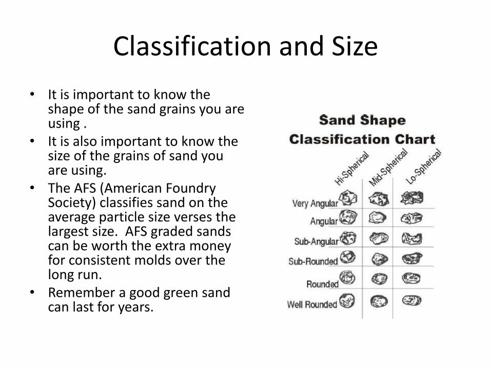
• It is important to know the shape of the sand grains you are using .
• It is also important to know the size of the grains of sand you are using.
• The AFS (American Foundry Society) classifies sand on the average particle size verses the largest size. AFS graded sands can be worth the extra money for consistent molds over the long run.
• Remember a good green sand can last for years.

Clay added to recipie
• Clay is added to the sand to act as a binding agent. You need to have enough clay in the mix to make a strong bond, but not so much clay that air is trapped in the mold
• Any fire clay will work (the Red Art clay we are using for the first molds is a fire clay). Fire clay is any clay that can withstand over 2765 degrees F and have fusion points over 2900 degrees F. If using most standard fire clays you will need to add 25-35% by weight.
• Bentonite clay is superior to standard fire clay and you only need 5-10% by weight. Its colloidal properties and grain size make it easier for the material to coat the grains of sand.
• Mix ingredients dry.

Other additives
• You also should add 1-2% of some sort of burnable “flour.”
• This adds to the water absorbing properties as well as having a material to burn and which in turn creates a gas shield between the metal and the sand.
• The best is coal dust, wood flour or graphite, but wheat or corn flour will actually work. Powdered wall paper paste is also particularly good.
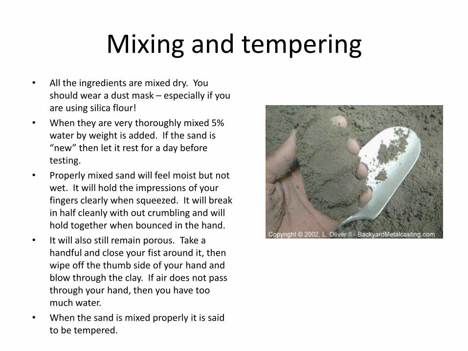
Mixing and tempering • All the ingredients are mixed dry. You
should wear a dust mask – especially if you are using silica flour!
• When they are very thoroughly mixed 5% water by weight is added. If the sand is “new” then let it rest for a day before testing.
• Properly mixed sand will feel moist but not wet. It will hold the impressions of your fingers clearly when squeezed. It will break in half cleanly with out crumbling and will hold together when bounced in the hand.
• It will also still remain porous. Take a handful and close your fist around it, then wipe off the thumb side of your hand and blow through the clay. If air does not pass through your hand, then you have too much water.
• When the sand is mixed properly it is said to be tempered.

Core Sands • Core sands will have additional binders that
give them extra strength
• The materials used for binders are primarily corn flour, dextrine, raw linseed oil, and commercial core oils. Corn flour and dextrine are cereal binders.
• Molasses and pitch are two materials which can be obtained easily for use as core materials. Molasses should be mixed with water to form a thin solution known as "molasses water." In this condition, it is added to the core mix as part of the temper water during the mulling operation. Pitch is seldom used alone. Used with dextrine, it imparts good strength to a core mix. Sea coal in small amounts is used with pitch to prevent the pitch from rehardening after it has cooled from the high temperatures caused by the molten metal.
• Oils such as linseed oil is also frequently used.
Core with chaplet to hold it in place.
Tools for sand molding
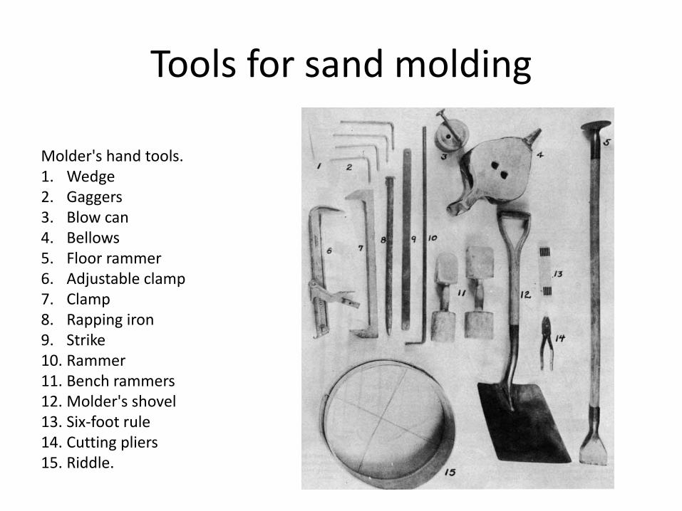
Molder's hand tools. 1. Wedge 2. Gaggers 3. Blow can 4. Bellows 5. Floor rammer 6. Adjustable clamp 7. Clamp 8. Rapping iron 9. Strike 10. Rammer 11. Bench rammers 12. Molder's shovel 13. Six-foot rule 14. Cutting pliers 15. Riddle.

Additional hand tools
1. Gate stick; 2. Brush; 3. Bosh or swab; 4. Level; 5. Trowels; 6. Camel's hair brushes; 7. Rapping or clamping bar; 8. Wrench; 9. Rawhide mallet; 10. Vent wire; 11. Slickers, double-enders, spoons; 12. Half-round corner; 13. Dogs; 14. Draw spike; 15. Draw screw; 16. Calipers; 17. Flash light; 18. Gate cutter; 19. Circular flange tool; 20. Circular flange tool; 21. Bench lifter (bent); 22. Hub tool; 23. Lifter; 24. Lifters.

Mold Flask
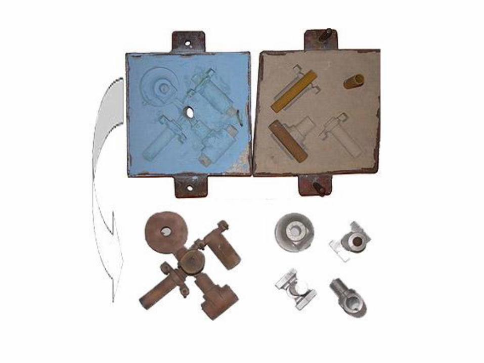

Pattern set in drag with gating system parts

Hand packing riddled sand around the pattern.

Ramming a deep pocket.

Striking off the drag
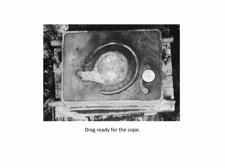
Drag ready for the cope.

Cope with pattern and gating pieces set.

Ramming the partially filled cope.

Venting the cope.

Start of the pattern draw.

Pattern completely drawn.

Setting the core.

Cope and drag ready for closing

Clamped mold with weights and pouring basin


Finished pump housing casting.

Propeller set in the drag.
Propeller in the drag with parting line cut.

Drawn cope
Mold ready for closing
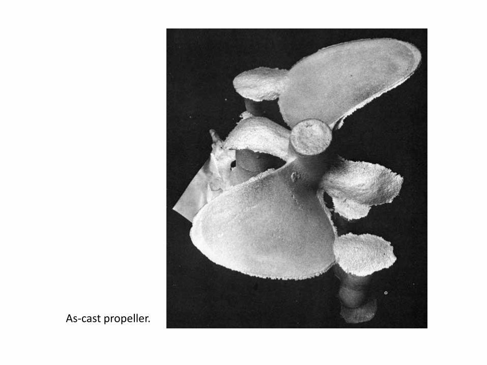
As-cast propeller.
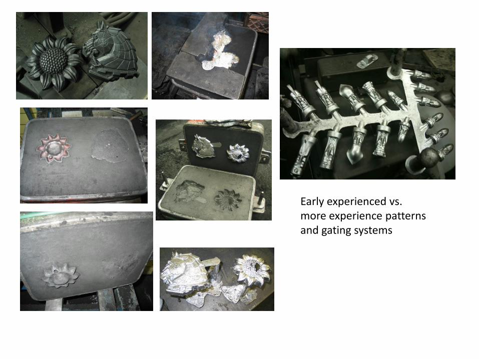
Early experienced vs. more experience patterns and gating systems

In a vertical sand molding machine the sand is mixed in a hopper above and then dropped into the flask. The operator may hand ram the sand or it may be rolled over to a mechanical press.
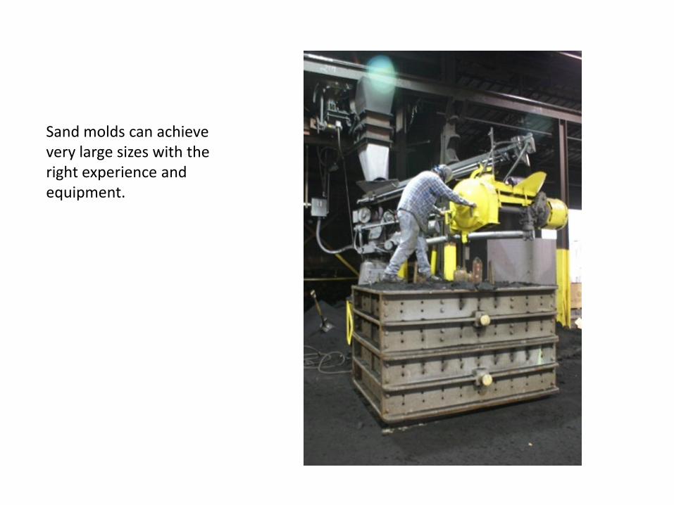
Sand molds can achieve very large sizes with the right experience and equipment.

Keene Foundry in Houston, Texas

Gating your mold

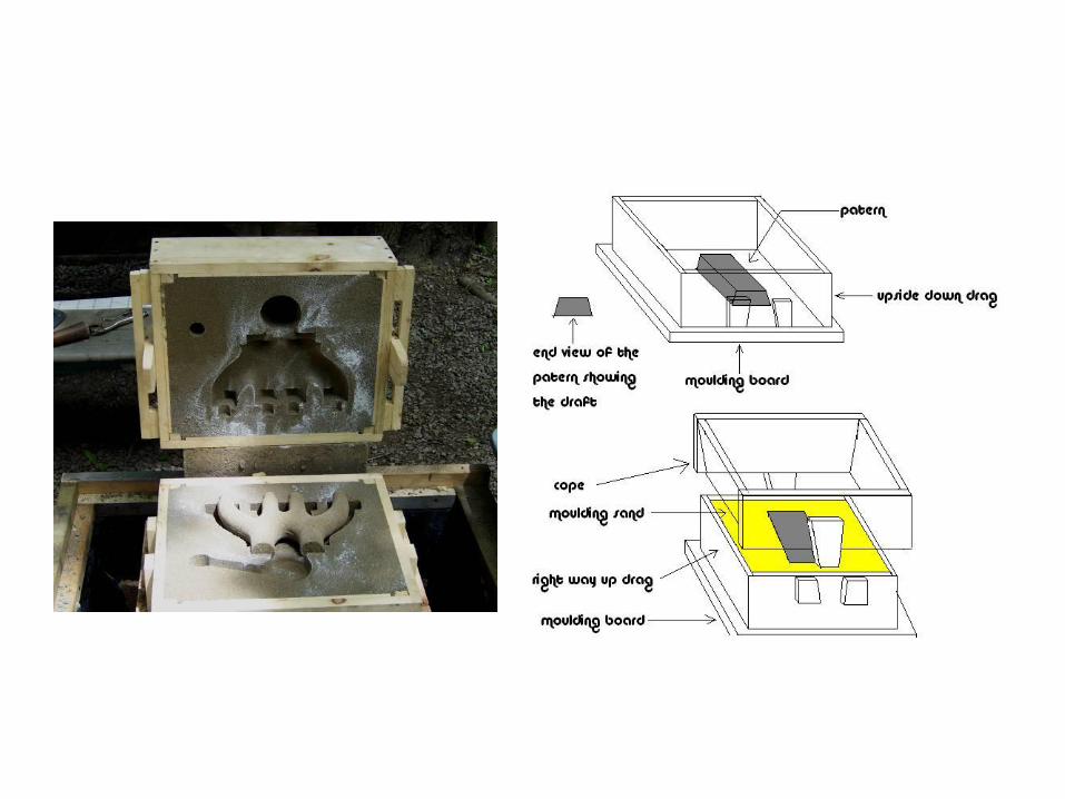
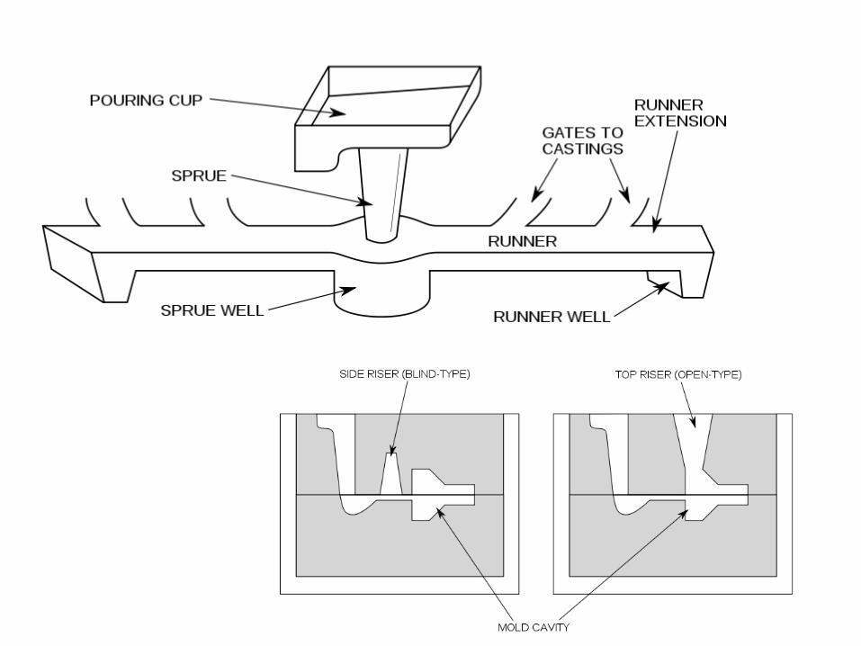
Parts of a Sand Mold
• Pouring cup - the molten metal is poured in here. It has a funnel shape to ease pouring accuracy problems.
• Runner / sprue - a sprue carries metal from the pouring cup to the runners. The runners distribute metal to the part.
• Gate - a transition from the runner to the cavity of the part
• Riser - a thermal mass where excess metal will remain in a liquid state while the part cools. As the cooling part shrinks, the molten metal in the riser will feed or fill in the shrinkage. Risers can also be used to collect impurities that rise in molten metal.
• Mold cavity - this is the final shape of the part, the pattern would be found here prior to molten material. Vent - a narrow escape passage for gases that would otherwise be trapped in the mold.
• Parting line - a line of separation that allows the mold (made in two pieces) to be put together to make a full cavity. Note that this line does not have to be a straight line, and is often staggered to make the mold making easier.
• Cope - the upper part of a casting mold • Drag - the lower part of a casting mold

There are important Casting Concepts about patterns
• Molds are made by compacting sand around the
shape of the pattern. • Patterns are made of wood, metal and plastics -
the material must be stronger if a large number of molds are to be made.
• A parting agent can be used on a pattern to allow easy removal after the mold is made.
• Pattern types include: a.] one piece patterns (loose or solid patterns) - low quantity simple shapes
• b.] split patterns - for complex shapes made in two patterns for each half of the part.
• c.] match plate - the split patterns are mounted in a single plate. This allows gating on the drag side to match up with the runners on the cope.
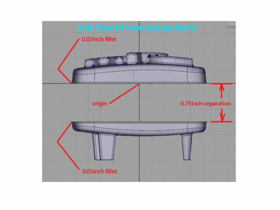
• d.] design of the patterns should include consideration of shrinkage
• e.] a slight taper should be added to the sides all patterns this will make them easy to remove from the completed mold. i.e. a cone is easier to remove than a cylinder.

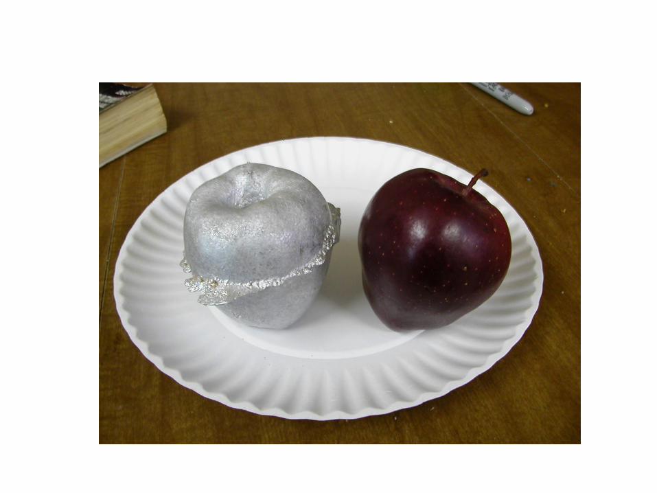
Which is correct?

Pouring a resin bonded sand mold. Note the shape of the stream of metal
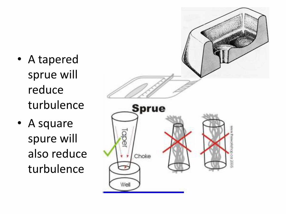
• A tapered sprue will reduce turbulence
• A square spure will also reduce turbulence
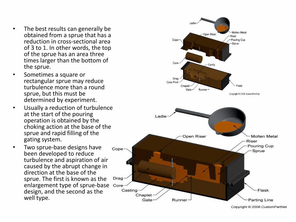
• The best results can generally be obtained from a sprue that has a reduction in cross-sectional area of 3 to 1. In other words, the top of the sprue has an area three times larger than the bottom of the sprue.
• Sometimes a square or rectangular sprue may reduce turbulence more than a round sprue, but this must be determined by experiment.
• Usually a reduction of turbulence at the start of the pouring operation is obtained by the choking action at the base of the sprue and rapid filling of the gating system.
• Two sprue-base designs have been developed to reduce turbulence and aspiration of air caused by the abrupt change in direction at the base of the sprue. The first is known as the enlargement type of sprue-base design, and the second as the well type.

More notes about gating
• 1. Use Rectangular Sprues. There are two schools of thought on the shape of the main down gate round vs. rectangular. Round does promote a quick pour, but the current thought is that rectangular gates, while potentially causing some turbulance, introduce the least amount of gas into the casting.
• 2. Taper the Sprue. The sprue should be tapered with the smaller end toward the casting. This makes is possible to keep the down-gate full of metal when pouring. Often a stepped taper is used. Never locate a tapered sprue so that metal is poured into the smaller end.
• 3. Streamline the Gating System. Gating systems having sudden changes in direction cause slower filling of the mold cavity, are easily eroded, and cause turbulence in the liquid metal with resulting gas pickup. Streamlining of the gating system eliminates or minimizes these problems. Avoid right-angle turns.
• (a) Round sprues are preferred for sprue diameters of 3/4 inch or less. Larger sprues should be square or rectangular. However, a 3/4 inch diameter sprue is about the maximum size that can be kept full of metal while hand pouring. (b) Wide flat gates and runners are preferred for light metal alloys.
• 4. Use Patterns for the Gates. The gating system should be formed as part of the pattern whenever possible. In the case of many loose patterns used aboard repair ships, gating patterns should be used instead of cutting the gates by hand. The use of patterns for the gates permits the sand to be rammed harder and reduces sand erosion or washing. Hand-cut gates expose loosened sand which is easily eroded by the flowing metal.
• 5. Maintain Proper Gating Ratio. There is a definite relationship between the cross-sectional areas of the sprue, runners, and in-gates, to produce the best filling conditions for the mold. The rate of filling the mold should not exceed the ability of the sprue to keep the entire gating system full of liquid metal at all times. The cross section of the runner should be reduced in size as each gate is passed. This keeps the runner full throughout its entire length and promotes uniform flow through all of the gates. If this procedure is not followed in a multiple-ingate system, all of the metal will have a tendency to flow through the ingates farthest from the sprue.

Risers
• Reservoirs of molten metal, known as risers, are required to make up for the contraction that occurs during solidification. If risers are not provided at selected spots on the casting, shrinkage voids will occur in the casting.
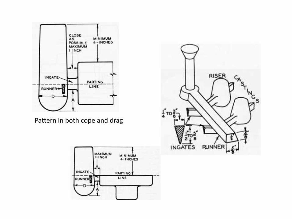
Pattern in both cope and drag

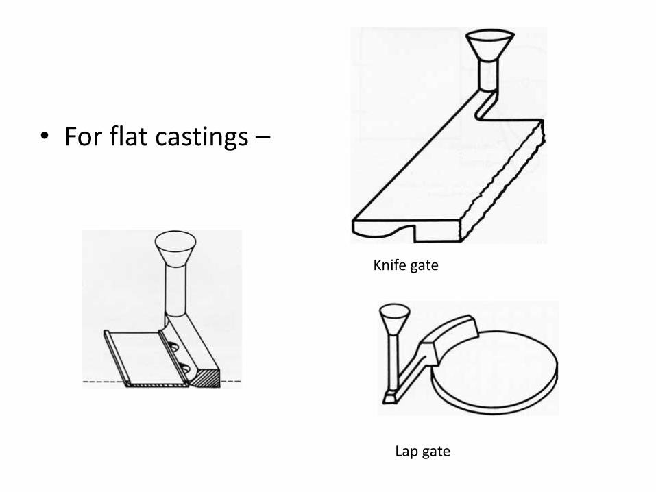
• For flat castings –
Knife gate
Lap gate


Shrinkage and Warp
• There is a great deal of variation in regards to metal for shrink, the deciding factors can include metal alloy, pouring temperature, mold type (hard molds allow for less shrink than soft ones) and freshness of alloy. With experience you can control these factors.
• Shrink and warpage also are dependent on the pattern. Thicker patterns will shrink more than a thinner one.
• There are general rules and pattern makers will make a “pattern ruler” which includes the variation in shrink. To allow for this, patterns are made slightly over sized. A pattern that is 12 1/8" long will produce a 12" long part when cast in iron. Shrink rules are elongated rulers that take shrinkage into account. (A one foot shrink rule with 1/8" shrink per foot looks like an ordinary ruler. It is actually 12 1/8" long.) By using a shrink rule to measure parts for a pattern, the pattern maker does not have to scale up the dimensions of the desired casting.
Walls of a pattern will pull in as the casting cools, if you start with the center pattern – your casting will look like the one on the right.

Shrink tear
• Resistance to contraction of the casting results in severe "contraction stresses" which may tear the casting or which may remain in the casting until removed by suitable heat treatment. Sharp internal corners are natural points for these stresses.
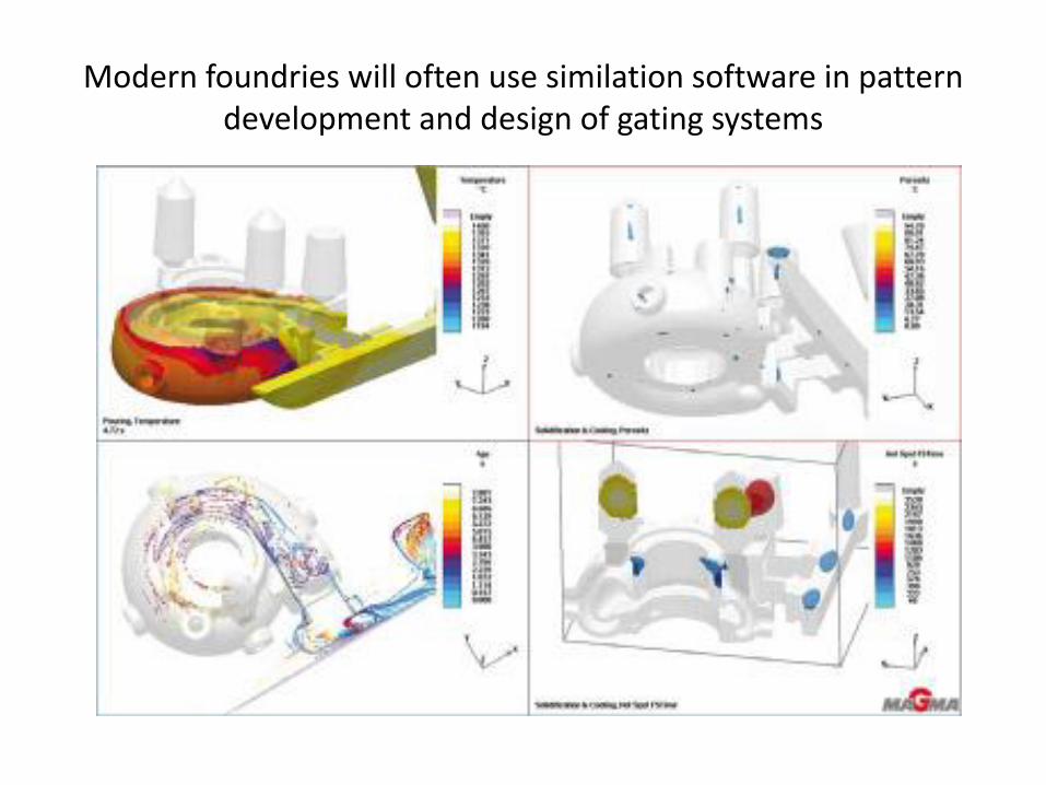
Modern foundries will often use similation software in pattern development and design of gating systems
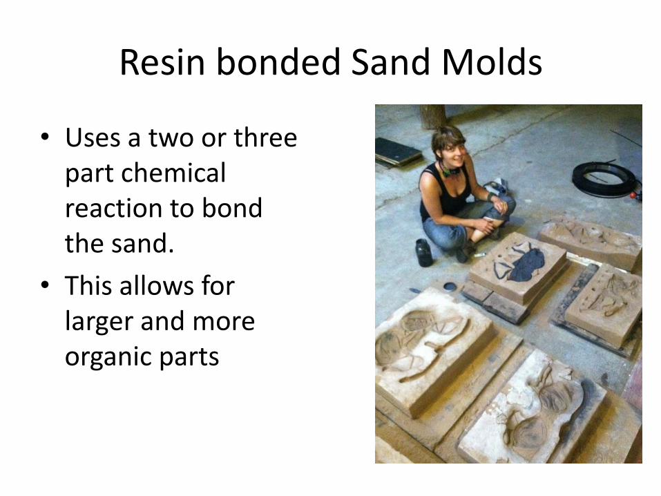
Resin bonded Sand Molds
• Uses a two or three part chemical reaction to bond the sand.
• This allows for larger and more organic parts

Bonded sand allows for the pattern to actually be carved into the mold

A series of open faced bonded molds

Stricking off the cope of a mold – note the corners blocked off to save on
sand
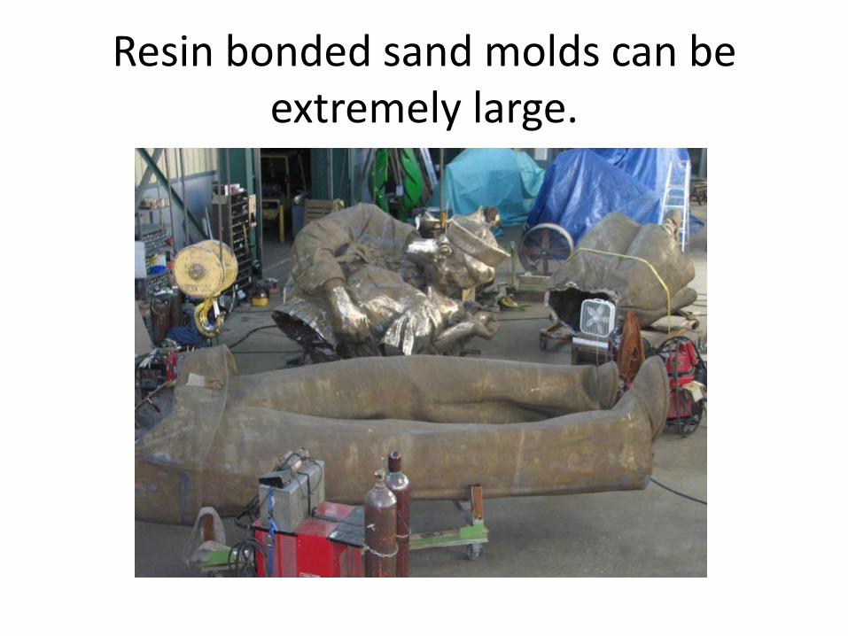
Resin bonded sand molds can be extremely large.

• Lost foam is a very easy and quick method of obtaining a casting. • First you create the pattern – gates and all out of foam. • Then you coat the pattern with a refractory slip – this helps to prevent the metal from burning into the sand. • Then you pack the pattern in moist (5% water) sand inside of a flask. • Finally you pour the mold – pattern in place. • There will be a horrible smoke that comes out of the mold – do not breath it as it contains cyanide! Use a respirator when pouring lost foam!

Process Chart for Lost Foam Casting