samsung galaxy s8 - pemnet.com · samsung galaxy s8 cellphone teardown step 11: removing the...
TRANSCRIPT

© 2017 www.pemnet.com 1 1
Samsung Galaxy S8
June 8th, 2017
XiaoMing Chen
PennEngineering®
© 2017 www.pemnet.com 2
Overview
2
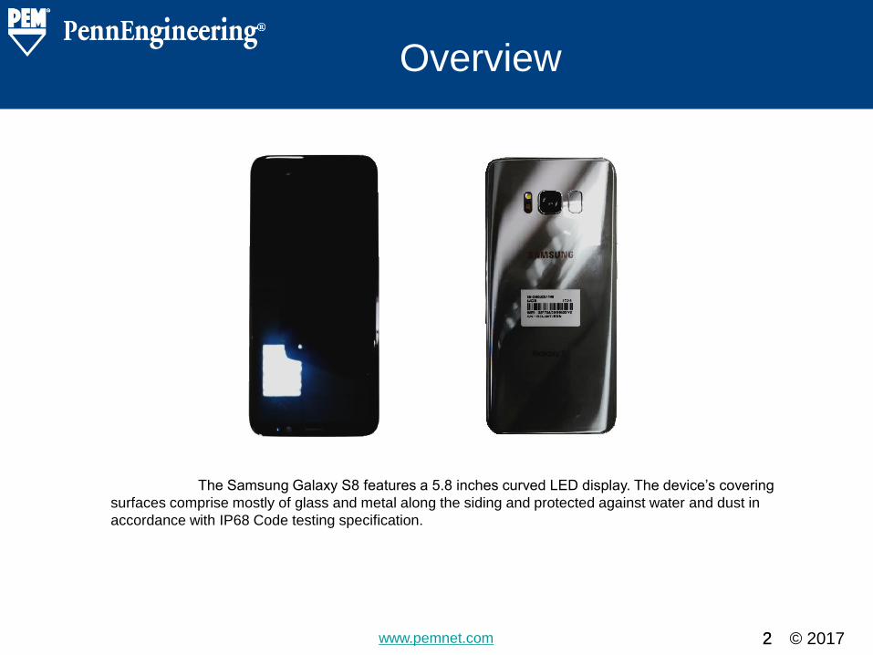
The Samsung Galaxy S8 features a 5.8 inches curved LED display. The device’s covering
surfaces comprise mostly of glass and metal along the siding and protected against water and dust in
accordance with IP68 Code testing specification.
© 2017 www.pemnet.com 3
Details & Findings
Pictures and Description of the
Samsung Galaxy S8 and the
Disassembly Process.
3
© 2017 www.pemnet.com
Samsung Galaxy S8 Cellphone Teardown
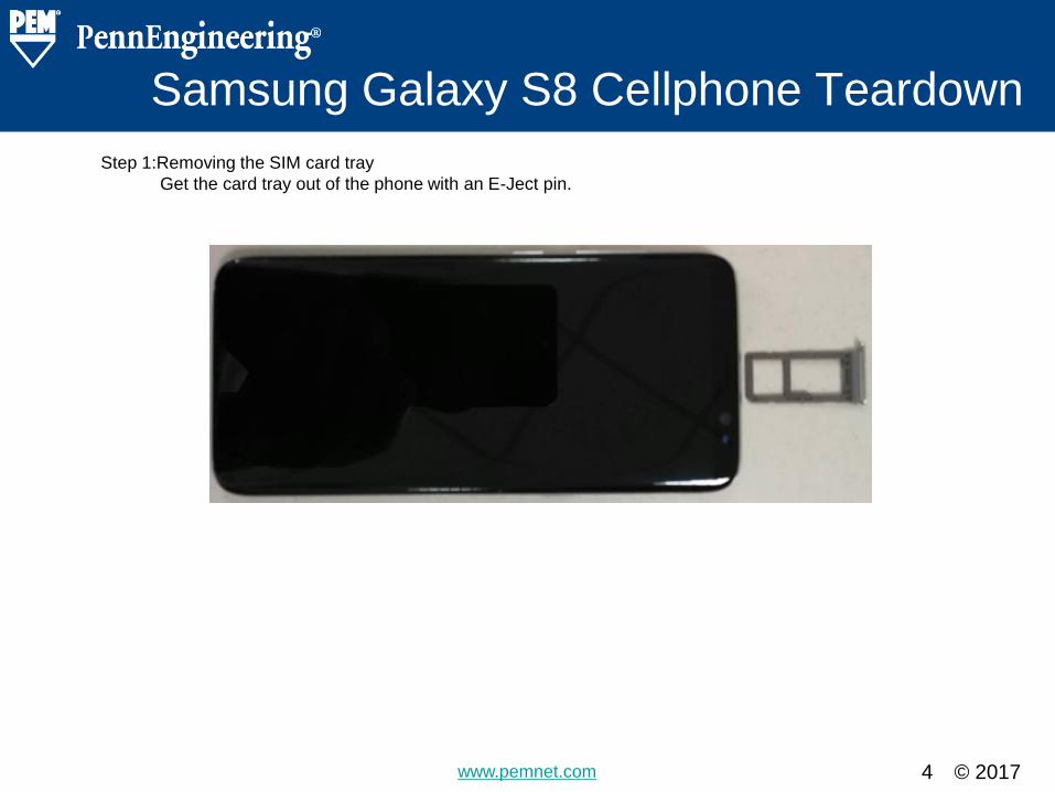
Step 1:Removing the SIM card tray
Get the card tray out of the phone with an E-Ject pin.
4
© 2017 www.pemnet.com
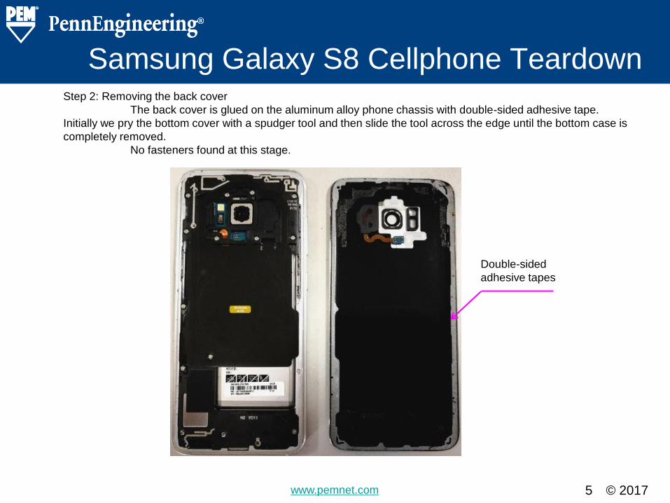
Samsung Galaxy S8 Cellphone Teardown Step 2: Removing the back cover
The back cover is glued on the aluminum alloy phone chassis with double-sided adhesive tape.
Initially we pry the bottom cover with a spudger tool and then slide the tool across the edge until the bottom case is
completely removed.
No fasteners found at this stage.
5
Double-sided
adhesive tapes

© 2017 www.pemnet.com
Samsung Galaxy S8 Cellphone Teardown
Step 3: Removing the camera lens and the flash cover glued on back cover
A flex cable and the camera cover are glued on the back cover with adhesives.
6

© 2017 www.pemnet.com
Samsung Galaxy S8 Cellphone Teardown Step 4: Removing the middle-plastic-contact.
We disconnect the flex cable and the signal cable prior to removing the middle-plastic-contact from the
aluminum alloy chassis. To remove the middle-plastic-contact we have to remove eight M1.4 screws (circled in Blue)
that hold the PC Board fastened on the molded aluminum alloy chassis illustrated on slide #8.
7
The screw details:
• M1.4 x 3.70 mm overall length
• 2.41 mm head diameter
• 0.6 mm head thickness
• Nylon locking patch
• Machined
• #00 Phillips drive
• Pan head
• Carbon Steel + Bright Nickel

© 2017 www.pemnet.com
Samsung Galaxy S8 Cellphone Teardown Step 4: Removing the middle-plastic-contact.
The picture below shows the internal threads that are machined in the molded aluminum alloy chassis
illustrated in the previous slide.
8

© 2017 www.pemnet.com
Samsung Galaxy S8 Cellphone Teardown Step 5: Removing the plastic-contact on the left side.
Three M1.4 screws (circled in Blue) are used to hold the left-plastic-contact fastened on the PC Board
under the aluminum alloy chassis. The threads are tapped in the molded aluminum alloy chassis illustrated on slide
#10.
9
The screw details are as below
• M1.4 x 3.70 mm overall length
• 2.41 mm head diameter
• 0.6 mm head thickness
• Nylon locking patch
• Machined
• #00 Phillips drive
• Pan head
• Carbon Steel + Bright Nickel

© 2017 www.pemnet.com
Samsung Galaxy S8 Cellphone Teardown Step 5: Removing the plastic-contact on the left side.
The picture below indicates the internal threads that are machined in the molded aluminum alloy
chassis that was mentioned in the previous slide.
10

© 2017 www.pemnet.com
Samsung Galaxy S8 Cellphone Teardown Step 6: Separating plastic-contact from the bottom-left side
Three M1.4 screws (circled in Blue) are used for holding the plastic contact at the bottom-left side and
PCB board. The screws eventually attach through the internal threads that are tapped on the aluminum alloy
chassis illustrated in the pictures below.
11
The screw details are as below
• M1.4 x 3.70 mm overall length
• 2.41 mm head diameter
• 0.6 mm head thickness
• Nylon locking patch
• Machined
• #00 Phillips drive
• Pan head
• Carbon Steel + Bright Nickel

© 2017 www.pemnet.com
Samsung Galaxy S8 Cellphone Teardown
Step 7: Removing the battery
The battery is held in position with double-sided adhesive tapes. The battery has to be removed to be
able to further proceed with disassembling the rest of the device. No mechanical fasteners found through this step.
12

© 2017 www.pemnet.com
Samsung Galaxy S8 Cellphone Teardown Step 8: Removing the motherboard
The motherboard itself pops out relatively simply. The I/O board connector is under the motherboard in
the aluminum alloy chassis.
Also no mechanical fastener found through this step.
13

© 2017 www.pemnet.com
Samsung Galaxy S8 Cellphone Teardown Step 9: Removing the bottom circuit board & earphone jack input module.
The signal cable has to be disconnected prior to removing the bottom circuit boards. The motherboard
is retained with five M1.4 screws (circled in Pink).
14
The screw details are as below
• M1.4 x 2.78 mm overall length
• 2.15 mm head diameter
• 0.5 mm head thickness
• Nylon locking patch
• Machined
• #00 Phillips drive
• Flat head
• Carbon Steel + Bright Nickel

© 2017 www.pemnet.com
Samsung Galaxy S8 Cellphone Teardown Step 9: Removing the bottom circuit board & earphone jack input module
The picture bellow shows the internal threads that are tapped inside the molded aluminum alloy
chassis.
15

© 2017 www.pemnet.com
Samsung Galaxy S8 Cellphone Teardown Step 10: Removing the stainless steel cover for the earphone jack input module.
The cover remains in position with the use of a molded positioning pin (circled in Blue) and fits in
outside dimensions of the cover and internal dimensions of the rectangular caves.
16

© 2017 www.pemnet.com
Samsung Galaxy S8 Cellphone Teardown Step 11: Removing the display assembly and the flex cable at the back of the screen
The screen is glued on the aluminum alloy chassis with double-sided adhesive tapes. It was quite
challenging to disassemble these 2 parts with the pry tool. The flex cable at the back of the screen is also adhered
with double-sided tape.
In this step, no mechanical fastener were found.
17

© 2017 www.pemnet.com
Samsung Galaxy S8 Cellphone Teardown
18
The below pictures include all the parts that were disassemble through the process.


© 2017 www.pemnet.com 20
Fasteners Summary
20
A total of 38 fasteners were identified in the device through-out the disassembly. All the fasteners are listed below:
Item Thread Overall
Length Head Dia. Head Thick. Driver Plating Nylock Qty. Slide No
1 M1.4 Screw 3.7 2.41 0.6 Phillips #00 Bright Nickel Yes 8 #7
2 M1.4 Screw 3.7 2.41 0.6 Phillips #00 Bright Nickel Yes 3 #9
3 M1.4 Screw 3.7 2.41 0.6 Phillips #00 Bright Nickel Yes 3 #11
4 M1.4 Screw 2.78 2.15 0.5 Phillips #00 Bright Nickel Yes 5 #14
5
M1.4
Micro Machined-in
Internal Threads
0.92 / / / Bright Nickel / 19 #8, #10, #15
6
0.8 x 1.5
Micro Molded
Positioning Pin
0.4 / / / / / 1 #16
© 2017 www.pemnet.com 21
Fasteners Summary
21
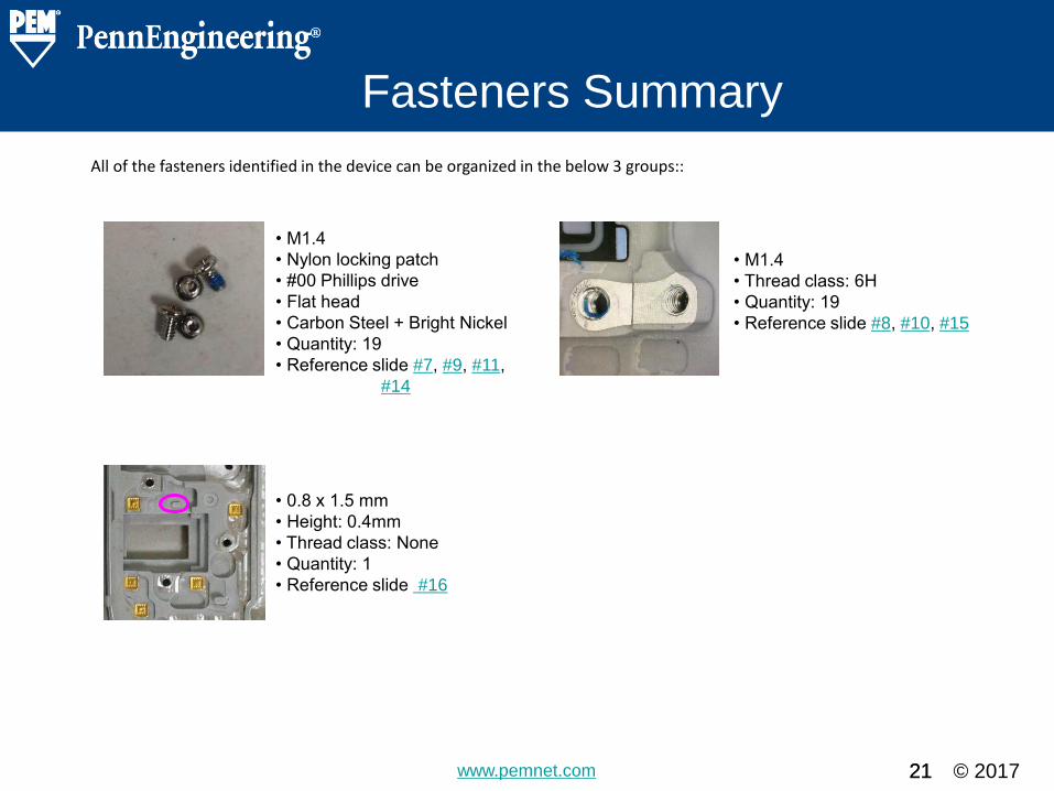
All of the fasteners identified in the device can be organized in the below 3 groups::
• M1.4
• Nylon locking patch
• #00 Phillips drive
• Flat head
• Carbon Steel + Bright Nickel
• Quantity: 19
• Reference slide #7, #9, #11,
#14
• 0.8 x 1.5 mm
• Height: 0.4mm
• Thread class: None
• Quantity: 1
• Reference slide #16
• M1.4
• Thread class: 6H
• Quantity: 19
• Reference slide #8, #10, #15

© 2017 www.pemnet.com
Alternate Solutions
PennEngineering® recommendations of alternate hardware and cost saving
opportunities.
22
Section Heading Slide – Do Not Remove

© 2017 www.pemnet.com
Alternate Solutions
Section Heading Slide – Do Not Remove
PennEngineering® is fully capable of making all of the fasteners shown on slides #7, #9, #11,
and #14. In addition to direct replacement and perhaps some manufacturing and material
substitution for functional and cost improvement, some alternate fastening suggestions are
presented for specific situations in the following slides.

© 2017 www.pemnet.com 24
Alternate Solutions
Section Heading Slide – Do Not Remove
• Micro screws alternative solution:
As an alternative approach, all of the micro screws can be replaced by PennEngineering®
manufactured micro screws. PEM has license with Microstix®, Torx® and Torx Plus® driver and
self-tapping thread patent as like TAPTITE®, FASTITE®, REMFORM® and REMFORM F® with
different design solutions.

© 2017 www.pemnet.com 25
Alternate Solutions
Section Heading Slide – Do Not Remove
• PEM TackSert parts:
In the disassembly process, screws are used to fix & connect PC board, earphone jack and
power charge on the main body.
In the case, PennEngineering® TackSert parts can be used in some locations. This however is a
permanent solution and cannot be reworked. The press-in installation will be quicker than the
turn-in screws.

© 2017 www.pemnet.com 27
Alternate Solutions
Section Heading Slide – Do Not Remove
• M1.4 Micro Machined-in Internal Threads alternative solution:
All of the M1.4 Micro Machined-in Internal Threads can be replaced with PennEngineering®
TS4™ microPEM® TackScrew™ Fasteners. The microPEM® TS4™ enables cost effective
sheet-to-sheet attachment by simply pressing into place and can be removed by unscrewing,
similar to original threaded fasteners.

© 2017 www.pemnet.com 28
Alternate Solutions
Section Heading Slide – Do Not Remove
• 0.8 x 1.5 Micro Molded Positioning Pin alternative solution I:
The Pin (circled in Pink) can be replaced by MPP™ microPEM® Self-clinching Pins. Ideal
for micro positioning and alignment applications, the Self-clinching Pins from
PennEngineering® can provide the MPPs with different sizes and types to meet the
application requirement.

© 2017 www.pemnet.com 29
Alternate Solutions
Section Heading Slide – Do Not Remove
• 0.8 x 1.5 Micro Molded Positioning Pin alternative solution II:
The Pin (circled in Pink) can also be replaced by the customized fastener YCHA-57222
positioning pin design (adjusted size and dimensions). Ideal for micro positioning and
alignment applications, PennEngineering® can provide special pins with different sizes and
types to meet the special requirements.

© 2017 www.pemnet.com 30
Alternate Solutions
Section Heading Slide – Do Not Remove
• Terminals alternative solution:
A total of 19 pieces of copper made terminals were welded to the aluminum alloy
chassis. The terminals can be replaced with PennEngineering® TA™/T4™ microPEM®
TackPin® Fasteners made from a high Electrical Conductivity Alloy (for example, C15100 or
C19800 alloys). The solution enables sheet-to-sheet attachment, replacing costly screw
installation in applications where disassembly is not required.
© 2017 www.pemnet.com
Through-out the disassembly process of the Samsung Galaxy S8 cellphone we
identified a total of 38 fasteners. The battery and most of the flex cables are held with double-
sided adhesive tapes. Despite all the fasteners, the Galaxy S8 Cellphone actually proved easy
to take apart with all components set in a well-organized manner.
PennEngineering® is fully capable of making all of the fasteners shown in this
teardown report. PennEngineering® can produce all of the fastening solutions used in this
cellphone within our current manufacturing facilities. In addition to direct replacement and
perhaps some manufacturing and material substitution for functional and cost improvement,
some alternate fastening suggestions are presented for specific cases.
By using the alternative solution of TS4™ microPEM® TackScrew™ Fasteners, the
tapped threads in slide #27 can be eliminated thus leading to significant cost savings. The
microPEM® TS4™ enables cost effective sheet-to-sheet attachment by simply pressing into
place and can be removed by simply unscrewing, similar to original threaded fasteners
The Ultrasonic Metal Welding machining cost can be effectively eliminated along with
some relative process disadvantages by replacing the 19 terminals in slide #30, with TS4™ or
TA™/T4™ or TKA™/TK4™ made of electrical conductive material.
Additional savings could be obtained by using microPEM® FASTENERS being fed,
positioned and installed automatically in an installation system to install fittings into the
components in this cellphone.
31
Section Heading Slide – Do Not Remove
Conclusions and Summary