samsung error code booklet
TRANSCRIPT

Samsung Error Code Booklet

Introduction
Welcome to the new Samsung Error Code Booklet, for our repair network.
This booklet has been designed to offer on site assistance for fault codeanalysis across the DVM S Samsung Smart Inverter range.
Please use this book when attending Service Calls as it will assist you withthe next steps on how to diagnose the system problem.
Should you need any further assistance please callTechnical Support on 1300 887 660 Option 1.
Split Systems ACCassette System ACDucted System ACFree Joint Multi AC
E101-120 Communication error related to indoor
E121-150 Indoor sensor related error
E151-200 Other errors related to indoor
E201-209 Communication error related to the outdoor unit
E210-220 Plumbing inspection error
E221-400 Outdoor unit sensor related error
E401-550 Protect the outdoor unit control / self-diagnosis related errors
E551-600 Other errors related to the outdoor unit
E601-650 OPTION instrument related errors
E652-700 Other error
P701-800 Protect the outdoor unit control Low Level Risk - indoor normal operation
P801-900 GHP-R410A, R22 outdoor unit related error
E901-920 Hydro indoor related errors
E921-999 Reserved
Displayed alphabet Explanation
E When displaying Error 101-700
P When displaying Error 701-800
When E206 occurs
Displays address of subordinate within the set
C001: HUB, C002: FAN, C003: INV1, C004: INV2
C
When MCU error occurs
Displays address of MCU
Ex) U200: Outdoor unit 1, U201: Outdoor unit 2, U202: Outdoor unit 3, U203: Indoor unit 4
U
When displaying outdoor unit address
Ex) U200: Outdoor unit 1, U201: Outdoor unit 2, U202: Outdoor unit 3, U203: Indoor unit 4
A
When displaying indoor unit address
Ex) A000: Indoor unit address 0, A001: Indoor unit address 1, A002: Indoor unit address 2
ERROR CODE EXPLANATION
MEANINGS OF FIRST ALPHABETICAL CHARACTER / NUMBER OF ERROR CODE
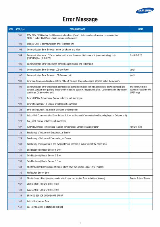
Error Message
1
101 DVM,DPM,DVS:Outdoor Unit Communication Error (Case” : Indoor unit can’t receive communication SINGLE: Indoor Unit Panel - Main communication error
102 Outdoor Unit -> communication error to Indoor Unit
103 Communication Error Between Indoor Unit Panel and Main
104 Communication error : “IF <_> Indoor unit” some disconnect in Indoor unit (communicating) only For GHP-R22 [GHP-R22] For [GHP-R22]
105 Communication Error in between sensing space module and Indoor unit
106 Communication Error Between LCD and Panel Verdi
107 Communication Error Between LCD Outdoor Unit Verdi
108 Error due to repeated address setting (When 2 or more devices has same address within the network)
109 Communication error that indoor address is not completed.Check communication wire between indoor and outdoor, outdoor unit quantity, indoor address setting status.K3 reset.Reset DMS. Communication address not confirmed Other outdoor unit
121 Error of ROOM Temperature Sensor in Indoor unit short/open
122 Error of Evaporator_in Sensor of Indoor unit short/open
123 Error of Evaporator_out Sensor of Indoor unitshort/open
124 Indoor Unit Communication Error (Indoor Unit _> outdoor unit Communication Error displayed in Outdoor unit)
125 Eva_mid2 Sensor of Indoor unit short/open
127 [GHP-R22] Indoor Temperature (Suction Temperature) Sensor breakaway Error For GHP-R22
128 Breakaway of Indoor unit Evaporator_in Sensor
129 Breakaway of Indoor unit Evaporator_out Sensor
130 Breakaway of evaporator in and evaporator out sensors in indoor unit at the same time
131 Sub(Electronic) Heater Sensor 1 Error
132 Sub(Electronic) Heater Sensor 2 Error
133 Sub(Electronic) Heater Sensor 3 Error
134 Shutter Sensor Error (In case of model which have two shutter, upper Error : Aurora)
135 Perfect Fan Sensor Error
136 Shutter Sensor Error (In case, model which have two shutter Error in bottom : Aurora) Aurora Bottom Sensor
137 VOC SENSOR OPEN/SHORT ERROR
138 GAS SENSOR OPEN/SHORT ERROR
139 ERV CO2 SENSOR OPEN/SHORT ERROR
140 Indoor Dust sensor Error
141 IAQ CO2 SENSOR OPEN/SHORT ERROR
SEG1 SEG2, 3, 4 ERROR MESSAGE NOTE
The communication address is not confirmed. (NASA only)

Error Message
2
SEG1 SEG2, 3, 4 ERROR MESSAGE NOTE
142 Indoor Unit Humid Sensor short/open
143 Sensing space Sensor Error
144 Eva2_in Sensor of Indoor Unit short/open Sensor attached duct of Eva2 for India
145 Eva2_out Sensor of Indoor Unit short/open Sensor attached duct of Eva2 for India
146 EEV Inlet Sensor short/open Sensor for EEV to know overheating rate
147 Indoor Eva2_in Sensor break away Error Sensor attached duct of Eva2 for India
148 Indoor Eva2_out Sensor break away Error Sensor attached duct of Eva2 for India
149 AHU Master Indoor room sensor setting error AHU
150 RESERVED(DMS-SNET3 Error) Refer to Error History
151 Open error of electoronic expansion valve in indoor unit(2nd)
152 Close error of electoronic expansion valve in indoor unit(2nd)
153 Dectect Indoor float s/w 2nd
154 Indoor unit Fan Error
155 Indoor unit Fan2 Error
156 Indoor unit (EEV2) open error 2nd Duct of Indoor unit EEV2 for India
157 Indoor unit (EEV2) close error 2nd Duct of Indoor unit EEV2 for India
158 UDoor upper operation Error (check Photo Sensor or operating Relay Error)
159 UDoor lower operation Error (check Photo Sensor or operating Relay Error)
161 Cooling and Heating mixed operating Error
162 Outdoor unit EEPROM error
163 EEPROM OPTION SETTING ERROR
165 Elect Discharge Temp Protect Error
166 Electric motor related to no wind Error
167 Unsing peripheral in Indoor Unit Option DIP S/W set Error
168 IAQ Safety S/W Open Error
169 AHU EEV Fault detection error AHU

Error Message
3
SEG1 SEG2, 3, 4 ERROR MESSAGE NOTE
170 Error; Fahrenheit /Celsius degree use same time (Indoor Unit which selected Celsius) 07.03 Applied DVM for Trane No applied for Domestic Europe
174 ERV + heat exchanger inlet temperature sensor short / open ERV+
175 Outdoor built-in indoor temperature sensor short / open error ERV+
177 In hydro box, take place emerency signal Error hydro box - Error display in outdoor unit
180 MCU SOL Valve cooling/heating opening 1st at the same time
181 MCU SOL Valve cooling/heating opening 1st at the same time
185 missconnect power line to Indoor Unit communication line
186 sMPI(SPI) Feedback Error
187 K1Filter Feedback Error
190 While in checking pipe, no change Temp in Eva_in or change Temp Eva_in of other Indoor unit
191 While in checking pipe, no change Temp in Eva_out or change Temp Eva_out of other Indoor unit
192 Indoor Unit COVER OPEN (Indoor unit switch for safety
193 Indoor Panel Zero-Crossing Error
194 Indoor Main Zero-Crossing Error
195 IAQ safety S/W Open Error
198 Error due to disconnected thermal fuse of indoor unit
199 Error in Display Status of No pipe checking
201 After complete Tracking 5 times, missmatching of the indoor unit numbers set with those communicated error (some of indoor unit disconnection)
202 System Down (All Indoor unit Short) due to Communication Error
203 Outdoor Unit Communication Error Between MAIN-- SUB
204 After completing Tracking 5 times, there is different with a number of set MCU and communicated MCU
205 Communication Error on all PBA within the outdoor unit C-Box, communication cable error Communication Error Between Outdoor Unit Inv Micom -- Fan Motor Micom
206 Communication Error Between Outdoor Unit Main PBA - Sub PBA
206-C001 HUB PBA communication error
206-C002 FAN PBA communication error
206-C003 INV1 PBA communication error
206-C004 INV2 PBA communication error
210 Can NOT communicate with MCU over 2 min

Error Message
4
SEG1 SEG2, 3, 4 ERROR MESSAGE NOTE
211 Indoor unit connected with confluence kit without continunity
212 Indoor unit connected with confluence kit and setting address was overlapped more than 3
213 MCU address not matched with indoor unit address
214 MCU address not matched with outdoor unit address
215 Rotary switch for indoor unit address in MCU was over lapped among MCUs
216 DIP switch for indoor unit setting was ON position even though indoor unit was not connected
217 DIP switch for indoor unit setting was OFF position even though indoor unit was connected
218 Setting number of indoor unit in MCU is larger than installed indoor units.
219 Error on temperature sensor located on MCU intercooler inlet (Short or Open) MCU Over Cooling In Sensor Open/Short
220 Error on temperature sensor located on MCU intercooler outlet (Short or Open) MCU Over Cooling Out Sensor Open/Short
221 OUT temperature SENSOR ERROR (OPEN/SHORT) - ERROR LEVEL: more than 4.9V(-50ºC), less than 0.4V(93ºC)
226 OUT_temperature temperature Sensor breakaway Error
231 COND_OUT Main temperature SENSOR ERROR (OPEN/SHORT) - ERROR LEVEL: More than 4.9V(-50ºC), less than 0.4V(93ºC)”
236 COND_OUT Sub1 temperature SENSOR ERROR (OPEN/SHORT) - ERROR LEVEL: More than 4.9V(-50ºC), less 0.4V(93ºC)”
237 COND temperature SENSOR ERROR (OPEN/SHORT) - ERROR LEVEL: More than 4.9V(-50ºC), less than 0.4V(93ºC)
241 COND_MID or COND OUT Sensor of Outdoor Unit breakaway Error
242 Outdoor Unit Heater Error
246 COND_OUT 1 breakaway
251 PWM DISCHARGE temperature SENSOR ERROR (OPEN/SHORT) - ERROR detect Condition: detect Outdoor temperature more than -10ºC - ERROR LEVEL: More than 4.95V(-30’C), less than 0.5V(151’C)
256 Fixed COMP 1 DCHRG SENSOR ERROR (OPEN/SHORT) - ERROR detect Condition: detect Outdoor temperature more than - ERROR LEVEL: More than 4.95V(-30’C), less than 0.5V(151’C)
257 Fixed COMP 2 DCHRG SENSOR ERROR (OPEN/SHORT) - ERROR detect Condition: detect Outdoor temperature more than -10ºC - ERROR LEVEL: more than 4.95V(-30’C),less than 0.5V(151’C)”
258 Fixed COMP 3 DCHRG SENSOR ERROR (OPEN/SHORT) - ERROR detect Condition: Outdoor temperature more than -10 detect ºC - ERROR LEVEL: more than 4.95V(-30’C),less than 0.5V(151’C)
261 Digital COMP_discharge Sensor breakaway Error
262 Fixd COMP1_discharge Sensor breakaway Error

Error Message
5
SEG1 SEG2, 3, 4 ERROR MESSAGE NOTE
263 Fixd COMP2_discharge Sensor breakaway Error
264 Fixd COMP3_discharge Sensor breakaway Error
265 SUMP temperature sensor breakaway (Main)
266 SUMP temperature sensor breakaway (Sub1)
267 High Pressure SENSOR breakaway ERROR
268 SUMP temperature sensor breakaway (Sub3)
269 SUCTION Sensor breakaway
270 Suction 2 temperature sensor is detached
271 Digital COMP Sump_temperature Digital SENSOR ERROR (OPEN/SHORT) - ERROR detect Condition: detect outdoor temperature -10ºC - ERROR LEVEL: more than 4.95V(-30’C), less than 0.5V(151’C)”
276 FIXED COMP1 Sump_temperature SENSOR ERROR (OPEN/SHORT) - ERROR detect Condition: detect outdoor temperature more than -10ºC - ERROR LEVEL: more than 4.95V(-30’C), less than 0.5V(151’C)”
277 FIXED COMP2 Sump_temperature SENSOR ERROR (OPEN/SHORT) - ERROR detect Condition: detect outdoor temperature -10ºC - ERROR LEVEL: more than 4.95V(-30’C), less than 0.5V(151’C)”
278 FIXED COMP3 Sump_temperature FIXED 3 SENSOR ERROR (OPEN/SHORT) - ERROR detect Condition: detect outdoor temperature more than -10ºC - ERROR LEVEL: more than 4.95V(-30’C), less than 0.5V(151’C)
291 High pressure SENSOR ERROR (OPEN/SHORT) while in operating COMP only, detect (shortError: less than 0.4v, Error detect),(OPENError: over 4.2v, Error detect)(DVM 4 HP Switch)
296 Low Pressure SENSOR ERROR (OPEN/SHORT) while in operating COMP only, detect (shortError: less than 0.4v, Error detect),(OPENError:over 4.7v, Error detect)”(DVM 4 LP Switch)
301 High Pressure SENSOR breakaway ERROR
306 Low Pressure SENSOR breakaway ERROR
307 Oil Balance Sensor SHORT/OPEN
308 SUCTION Sensor SHORT/OPEN
309 Oil Balace Sensor2 Sensor SHORT/OPEN
310 Oil Balance Sensor3Sensor SHORT/OPEN
311 Double pipe Sensor SHORT/OPEN
312 Main Cooling Sol Valve Open Error
313 4-Way Valve operation Error
314 Oil Balace Sensor4 SHORT/OPEN
315 CT1 Sensor Short or Open
316 CT2 Sensor Short or Open

Error Message
6
SEG1 SEG2, 3, 4 ERROR MESSAGE NOTE
317 CT3 Sensor Short or Open
320 OLP Sensor SHORT / OPEN
321 EVI INLET Sensor SHORT/OPEN
322 EVI OUTLET Sensor SHORT/OPEN
323 Error on suction sensor 2 (Short or Open
324 Outdoor Unit Fan Motor Current Sensor SHORT / OPEN
325 Outdoor Unit Fan2 Motor Current Sensor SHORT / OPEN
326 Error on Total suction sensor (Short or Open)
330 Outdoor plumbing inlet sensor out 0 time (TA_0)
331 Outdoor sensor out once the entrance pipe (TA_1)
332 2, the inlet pipe outdoor sensor out (TA_2)
333 Three times the inlet pipe outdoor sensor out (TA_3)
334 Outdoor four times the inlet pipe sensor out (TA_4)
335 Outdoor pipe exit sensor out 0 time (TB_0)
336 1 outdoor sensor out pipe outlet (TB_1)
337 Outdoor sensor out two times pipe outlet (TB_2)
338 Outdoor sensor out three times pipe outlet (TB_3)
339 Outdoor sensor out four pipe outlet (TB_4)
346 Error due to operation failure of Fan2
347 Motor wire of Fan2 is not connected
348 Lock error on Fan2 of outdoor unit
353 Error due to overheated motor of outdoor unit’s Fan2
355 Error due to overheated IPM of Fan2.
361 2 CT1 inverter compressor start failure, or a low-current
364 Error due to over-current of inverter compressor 2. 2 DC Peak Inverter compressor stop.
365 V-limit error of inverter compressor 2. 2 inverter compressor overload stops (30A or more).
366 Error due to over voltage /low voltage of inverter PBA2. Less than 2 DC Link Voltage 150V 410V inverter over.
367 Error due to unconnected wire of compressor 2. Inverter compressor rotation over 2 Wire dependence or compressor
368 Output current sensor error of inverter PBA2. 2 Comp inverter current sensor error.
369 DC voltage sensor error of inverter PBA2. 2 DC Link Inverter Sensor Error.
371 2 inverter outdoor unit EEPROM Read / Write error (OTP error)

Error Message
7
SEG1 SEG2, 3, 4 ERROR MESSAGE NOTE
374 Heat sink temperature sensor error of inverter PBA2. 2 inverter heat sink temperature sensor error.
378 Hall IC connection error of Fan2. Outdoor fan 2 IPM H / W OC
383 Error due to special overcurrent of Fan2
385 Error due to input current of inverter 2. 2 inverter input current sensor Error.
386 Over-voltage/low-voltage error of Fan2
387 Outdoor fan 2 Hall Sensor Error
389 V-limit error on Fan2 of compressor
391 Fan Controller 2 EEPROM Read / Write Error
393 Output current sensor error of Fan2. Fan Controller 2 Current sensor error.
396 DC voltage sensor error of Fan2. Fan Controller 2 DC Link sensor error.
399 Heat sink temperature sensor error of Fan2. 2 fan controller heatsink temperature sensor error.
400 Error due to overheat caused by contact failure on IPM of Inverter PBA2
401 Outdoor Freezing detect 1
402 Outdoor Freezing detect 2
403 Outdoor Freezing detect 3 - Freeze COMP DOWN
404 Outdoor overload 1 Protection Control Error
405 Outdoor overload 2 Protection Control Error
406 Outdoor overload 3 Protection Control Error
407 COMP down due to High PressureSensor Protection Control 1
408 COMP down due to High PressureSensor Protection Control 2
409 COMP down due to High PressureSensor Protection Control 3
410 COMP down due to Low PressureSensor Protection Control 1
411 COMP down due to Low PressureSensor Protection Control 2
412 COMP down due to Low PressureSensor Protection Control 3
413 Outdoor SUMP DOWN_1 Protection Control
414 Outdoor SUMP DOWN_2 Protection Control
415 Outdoor SUMP DOWN_3 Protection Control
416 Outdoor DischargeTemperature _1 Protection Control
417 Outdoor DischargeTemperature _2 Protection Control
418 Outdoor DischargeTemperature _3 Protection Control
419 Outdoor EEV#1 opening 6th Self-Check Error

Error Message
8
SEG1 SEG2, 3, 4 ERROR MESSAGE NOTE
420 Outdoor EEV#2 opening 6th Self-Check Error
421 Outdoor EEV#3 opening 6th Self-Check Error
422 Outdoor EEV#1 closing 6th Self-Check Error
423 Outdoor EEV#2 closing 6th Self-Check Error
424 Outdoor EEV#3 closing 6th Self-Check Error
425 Outdoor Reverse Phase or Missing Phase detect 1 Error
426 Outdoor Reverse Phase or Missing Phase detect 2 Error
427 Outdoor Reverse Phase or Missing Phase detect 3 Error
428 COMP down by Compression Ratio control Error 1
429 COMP down by Compression Ratio control Error 2
430 COMP down by Compression Ratio control Error 3
431 Oil Balance Valve1 Error
432 Oil Balance Valve2 Error
433 Oil Balance Valve3 Error
434 Oil Balance Valve opening Error (In DVM PLUS 2, HotGasValve Opening Error)
435 Water Cooling Flow Switch Error
436 Evaporator Protect for Freeze and Burst Error
437 Oil Balance Valve Closing Error(In DVM PLUS 2, HotGasValve Opening Error)
438 EVI EEV Opening Error
439 Error due to refrigerant leakage
440 Forbid Heat mode operation when outdoor temperature is over 30ºC
441 Forbid Cooling Mode when OutdoorTemperature ia less than -5ºC
442 Forbid an operation during heat mode with refrigerant charging operation when out door temperature is over 15ºC
443 Before Cooling working, less than Low Pressure 1K(inability to re-operate)
445 CCH is detached. CCH Self-Check Error (CCH malfunction Or Sump Sensor miss connection).
446 Error due to operation failure of Fan1. Fan Controller 1 Fan failed maneuver.
447 Motor wire of Fan1 is not connected. Fan controller wiring 1 Wire U.S.
448 Lock error on Fan1. Fan Controller 1 Lock error.
450 COND High Temperature(Protection Control) Every Time
451 Low Pressure Switch Low Pressure(Protection Control)
452 Instant power off Error (delete when COMP re-operate) Outdoor Zero-Crossing Error

Error Message
9
SEG1 SEG2, 3, 4 ERROR MESSAGE NOTE
453 Outdoor Fan high temperaturet Error
454 OutdoorFan RPM Error (more than 2500rpm and the difference that target velocity compare with practical velocity is more than 100rpm per 10SEC, more than 10 times)
455 OutdoorFan IPM(Internal PCB Module) high temperature Error
456 OutdoorFan Overcurrent Error
457 OutdoorFan Reversed direction of the wind Error
458 Outdoor unit Fan (Fan Error) Or CT1 over currency
459 Outdoor unit IPM Fault Error Or CT2 over currency
460 Outdoor unit communication-power disconnected detect Or CT3 over currency
461 Inverter COMP operating failure Or CT1 low currency
462 All currency control COMP Stop Or CT2 low currency
463 OLP Temperature control COMP Stop Or CT3 low currency
464 DC Peak COMP stop
465 COMP Overload stop(over 30A )
466 DC Link voltage less than 150V,over 410V
467 COMP revolute error Or COMP Wire In-connection
468 Inv Comp Current Sensor Error
469 DC Link Sensor Error
470 Outdoor unit EEPROM Read/Write Error
471 Outdoor unit EEPROM Read/Write Error(OTP error)
472 Outdoor unit Zero crossing Error
473 inverter Comp Lock Error
474 Heat sink temperature sensor error of inverter PBA1
475 Outdoor unit BLDC Fan 2 Error Or OutdoorFan2 RPM Error (more than 2500rpm and the difference that target velocity compare with practical velocity is more than 100rpm per 10SEC, more than 10 times)
476 4wAY Error detect Self-Check, After 6 times, COMP DOWN
477 Control for protecting liquid refigerant
478 Error due to over current of Fan1. OutdoorFan IPM H/W OC.
479 4WAY miss connection detect Error PAC Fixed
480 Fixed Comp 1 Stege OLP Protection Control(leakage for refrigerant Error)
481 Comp1 operating Error Duct for India
482 Comp2 operating Error Duct for India

Error Message
10
SEG1 SEG2, 3, 4 ERROR MESSAGE NOTE
483 Overvoltage of H/W Detect DC Link INV
484 PFC Overload (overcurrent) Error
485 Error due to input current of inverter 1. Input current Sensor Error.
486 Error due to over voltage/low voltage of Fan. Outdoor Fan DC-Link Voltage Under/Over Error.
487 Hall IC error of Fan1. Outdoor Fan Hall Sensor Error.
489 V-limit error on Fan1 of compressor
490 Outdoor Temperature 0 deegree & Indoor Temperature less than 0 deegree prohibition to operate ERV Ventilation System
491 Fan Controller1 EEPROM Read/Write Error
492 Outdoor Fan2 IPM H/W OC
493 Output current sensor error of Fan1. Fan Controller1 Current Sensor Error.
494 Delayed time Error due to OutdoorFan2 Fan Error
495 Outdoor Fan2 Overheat Error
496 DC voltage sensor error of Fan1. Fan Controller1 DC Link Sensor Error.
497 Outdoor Fan2 Overcurrent Error
498 Outdoor Fan2 IPM(Internal PCB Module) Overheat Error
499 Heat sink temperature sensor error of Fan1. Fan Controller1 Heat Sink Temp Sensor Error.
500 IPM Overheat Error for Inverter COMP
503 Error due to alert the user to check if the service valve is closed
504 Error due to self diagnosis of compressor operation
505 Error due to self diagnosis of high pressure sensor
506 Error due to self diagnosis of low pressure sensor
512 RESERVED(DMS-SNET3 Error) Refer to Error History
551 Defrost working
552 Low Discharge Pressure
553 equability operation
554 loading_failure / total Leakage of Refrigerant of Outdoor Unit side of COMP1 of Duct for India
555 Recovery of oil
556 Outdoor Unit power set option Error
557 When DPM mode, Product option are not same between indoor units
559 indoor Unit operating stop due to detect unknown error in Outdoor Unit

Error Message
11
SEG1 SEG2, 3, 4 ERROR MESSAGE NOTE
560 Outdoor Unit Switch option setting error(not applied)
561 Outdoor Unit SA(SUPPLY AIR) FAN RPM
562 Outdoor Unit RA(ROOM AIR) FAN RPM
563 indoor Unit mixed install error
564 IAQ Clean Fan Error
565 Miss connection Error between Comp and power wire - power line of Eva1 connect with Comp2 or Duct for India power line of Eva2 connect with Comp1
570 Boot Code Check FAIL
573 Error due to using single type outdoor unit in a module installation
574 Total Leakage of Refrigerant of Outdoor Unit 2 Comp2 side of Duct for India
575 Total Leakage of Refrigerant of Outdoor Unit 3 (Comp1, Comp2 bot detected) Duct for India both detect
601 Wire LCD <_> Indoor Unit Communication Error
602 Master Wire LCD <_> Slave Wire LCD Communication Error
603 Communication Packet Error (Baudrate / different communication type)
604 Wire LCD <_> Indoor Unit Tracking Error over 10 times
605 7 Day Scheduler <_> Wire LCD ,CAUR Communication Error
606 Wire LCD COM1/COM2 Cross Install Error
607 Wile Wire LCD Master-Master installation, Communication Error
608 External linkage ERV Controller No installation Error
609 External linkage Indoor No installation Error
610 CAUR <_> Transmitter Communication Error
611 DMS <_> CAUR Communication Error
612 DMS <_> PEAK Transmitter Communication Error
613 DMS <_> PIM/SIM Transmitter Communication Error
614 Amount of eletricity syste <_> PIM/SIM Transmitter Communication Error
615 Transmitter <_> Indoor unit Communication Error (After complete Transmitter Tracking, for 2min some indoor unit can’t communicate.)
616 Transmitter <_> Outdoor unit Communication Error (After completeTransmitter Tracking, for 2min outdoor unit can’t communicate)
617 Peak power Transmitter <-> Demand Controller Communication Error, Demand Transmitter <-> Amount of eletricity system communication Error
618 ERV Controller+indoor unit (16EA) over Max install number Error

Error Message
12
SEG1 SEG2, 3, 4 ERROR MESSAGE NOTE
619 celcius/fahrenheit indoor unit mixed install Error (out of indoor unit connected with New wire LCD, “Celcious/Fahrenheit” indoor unit mixed install)
620 New Wire Remote controller “celcious/Fahrenheit” Set Error (Dip S/W #4 Set Error)
621 New Wire Remote controller Master/Slave Dip Switch option Set Error (Difference with set option of Master and Slave)
622 Demand Controller / select the type of amount of electricity system Error
623 Demand Transmitter PT / CT ratio set Error
624 Demand Transmitter data receive error from amount of electricity
625 Master DMS ? Slave DMS Communication Error
626 ERV linkage wire remote controller(AWR-WE00) ERV separate installation Error (not connect indoor unit and, only ERV be installed) indoor unit linkage wire remocontroller(AWR-VH10) indoor unit separate installation Error (not connect indoor unit and, only ERV be installed)
627 While in linkage controll Master/Slave Wire Remote controller, Slave Wire Remote controller 2EA installation Error (Installing Wire Remocontroller set slave in Master Wire Remocontroller 2EA at the same time)
628 DMS <_> Transmitter Communication Error
629 DMS <_> DDC Communication Error
630 ERV wire remote controller normal ventilation option set Error - Check normal ventilation option set only. - ERV normal ventilation No option, use Wire Remote controller option normal ventilation
631 ERVWire Remote controller auto ventilation option set Error - Check set auto ventilation only - ERV auto ventilation no option, use wire remote controller auto ventilation
632 Error when input the pulse except set the value of Pulse Width by PIM 1. less than 20ms , 2. over 400ms , 3. over range of set pulse width, 4. repeated purse over 3min
652 While COM 1 Dual Master installation Commnunication Error
653 temperature Sensor Open/Short Error
654 FRAM Error or damper Error(ERV model)
655 RESERVED(DMS-SNET3 Error) Refer to Error History
656 RESERVED(DMS-SNET3Error) Refer to Error History
701 float 1st
702 Indoor EEV clsosing 1st
703 Indoor EEV opening 1st
720 Outdoor EEV#1 opening Self-Check Every time error
721 Outdoor EEV#2 opening Self-Check Every time error
722 Outdoor EEV#3 opening Self-Check Every time error
723 Outdoor EEV#1 closing Self-Check Every time error
724 Outdoor EEV#2 closing Self-Check Every time error

Error Message
13
SEG1 SEG2, 3, 4 ERROR MESSAGE NOTE
725 Outdoor EEV#3 closing Self-Check Every time error
768 RESERVED(DMS-SNET3) Error History
801 [GHP-R410A] communication error : “IF <_> Outdoor unit” : Disconnection
802 [GHP-R410A] communication error : “Outdoor unit <_> IF” : Disconnection
803 [GHP-R410A] communication error : “IF <_> Indoor unit” some disconnect in Indoor unit (communicating)
804 [GHP-R410A] communication error : Among outdoor unit
805 [GHP-R410A] Error setting ourdoor unit organization
806 [GHP-R410A] Remocon Sensor disconnect/short circuit
807 [GHP-R410A] outdoor liquid pipe Sensor disconnect/short circuit
808 [GHP-R410A] outdoor Unit - overcooling heat exchanger entry temp thermystor disconnect/short circuit
809 [GHP-R410A]COMP suction temp overheat
810 [GHP-R410A] COMP suction superheat not soar
811 [GHP-R410A] refrigerant high pressure Switch disconnect
812 [GHP-R410A] Gas EEV Output error
813 [GHP-R410A] refrigerant low pressure Sensor error(2nd)
814 [GHP-R410A] refrigerant high pressure Sensor error 1
815 [GHP-R410A] refrigerant high pressure Sensor error 2 (value of high pressure sensor less than standard low pressure)
816 [GHP-R410A] Water Pump operation failure
817 [GHP-R410A] Water Pump a number of revolute error
818 [GHP-R410A] IPM(outdoor unit FAN operating Driver) error
819 [GHP-R410A] outdoor heat exchange Fan 1 operating failure
820 [GHP-R410A] outdoor heat exchange Fan 2 operating failure
821 [GHP-R410A] outdoor heat exchange Fan 3 operating failure
822 [GHP-R410A] outdoor heat exchange Fan 1 a number of revolute error
823 [GHP-R410A] outdoor heat exchange Fan 2 a number of revolute error
824 [GHP-R410A] outdoor heat exchange Fan 3 a number of revolute error
825 [GHP-R410A] outdoor Unit - heat exchange Fan error
826 [GHP-R410A] outdoor Unit - Accum exit temp thermystor 1 disconnect/short circuit
827 [GHP-R410A] outdoor Unit - Accum exit temp thermystor 2 disconnect/short circuit
828 [GHP-R410A] outdoor unit Unit - refrigerant low pressure Switch disconnect
829 [GHP-R410A] refrigerant low pressure error

Error Message
14
SEG1 SEG2, 3, 4 ERROR MESSAGE NOTE
830 [GHP-R410A] three phase error
831 [GHP-R410A] one phase power part error
832 [GHP-R410A] Main - Sub MICOM Program Version Unmatch
833 [GHP-R410A] indoor unit connection number Over
834 [GHP-R410A] indoor unit connection capacity Over
835 [GHP-R410A] outdoor-indoor connection Unmatch
836 [GHP-R410A] Outdoor Unit -Regular Inspection
837 [GHP-R410A] Refrigerant High pressure error 1
838 [GHP-R410A] Refrigerant High pressure error 2
841 [GHP-R410A] Outdoor Unit Gas Temp Thermistor short/disconnection
843 [GHP-R410A] Engine water temp Sensor short/disconnection
844 [GHP-R410A] Engine discharge temp Sensor disconnection
845 [GHP-R410A] Engine fluid pressure error
846 [GHP-R410A] Engine Fluid pressure Switch disconnected
847 [GHP-R410A] Engine over revolute 1
848 [GHP-R410A] Engine over revolute 2
849 [GHP-R410A] Starter Error
850 [GHP-R410A] Engine a number of revolute control error
851 [GHP-R410A] Engine Stop
852 [GHP-R410A] IGUNAITA(firer) low voltage
853 [GHP-R410A] IGUNAITA(firer) disconnect
854 [GHP-R410A] IGUNAITA(firer) over voltage
855 [GHP-R410A] Engine discharge temp Error
856 [GHP-R410A] Engine water temp overheat
857 [GHP-R410A] Engine operation failure
858 [GHP-R410A] Engine cooling
859 [GHP-R410A] Engine insufficient operating revolute
860 [GHP-R410A] Engine a number of revolute Haunting Error
861 [GHP-R410A] COMP discharge temperature overheat
862 [GHP-R410A] Compressor Discharge temperature Sensor1 short/disconnection
863 [GHP-R410A] Compressor Discharge temperature Sensor2 short/disconnection

Error Message
15
SEG1 SEG2, 3, 4 ERROR MESSAGE NOTE
864 [GHP-R410A] Compressor Discharge temperature Sensor3 short/disconnection
865 [GHP-R410A] Compressor Discharge temperature Sensor4 short/disconnection
866 [GHP-R410A] Compressor nhale temperature Sensor1 short/disconnection
867 [GHP-R410A] Compressor suction temperature Sensor2 short/disconnection
868 [GHP-R22] Outdoor Unit - Accum Entrance Temperature Sensor short/disconnection
869 [GHP-R22] Outdoor Unit - refrigerants Gas pipe temperature Sensor short/disconnection
870 [GHP-R22] Outdoor Unit - comp lubricating oil insufficiency error
871 [GHP-R22] Outdoor Unit - Refrigerant overfill error
872 [GHP-R22] Outdoor Unit - Compressor induction temperature error
873 [GHP-R22] Engine cooling system Error
874 [GHP-R22] Engine Oil System error
875 [GHP-R22] Engine power system Error
876 [GHP-R22] Engine operating/control system Error
880 [GHP-R410A] Outdoor Unit - Engine Temp of Cooling water low
881 [GHP-R410A] Outdoor Unit - leakage of Engine oil
882 [GHP-R410A] Outdoor Unit - Lack of Comp oil
883 [GHP-R410A] Outdoor Unit - starter Trans voltage short
901 Water Inlet Sensor(Tw1) SHORT / OPEN
902 Water Outlet Sensor(Tw3) SHORT / OPEN
903 PHE Sensor(Tw2) SHORT / OPEN
904 Water TANK Sensor SHORT / OPEN
905 SOLAR Sensor SHORT / OPEN
907 Prevention hydro unit from freezing burst 1Time Check circulating water flow
908/909 Prevention the hydro unit from freezing Check circulating water flow 3Times
910 Breakaway of water out temperature sensor Check the location and connection state of water out temperature sensor
911 Less water flow than the minimum water flow (Differential water pressure/Flow Swtich Open Error
912 Flow Swtich Close Error

Error Message
16
SEG1 SEG2, 3, 4 ERROR MESSAGE NOTE
918 No feedback interlock signal of pump operation
971 Open or short of the room temperature sensor (Water law application based on room temperature)
972 Open or short of water in pressure sensor Check the PCB connection status and whether the sensor is defective or not
973 Open or short of water out pressure sensor
974 Open of short of external water out temperature sensor
UP
Trial operation incompleted (UnPrepared) - It will be cleared when trial operation was executed for 1 hour or when automatic inspection is completed

17
Outdoor Unit Error Display
POWER OFF / VDD NG
LED ON
LED DisplayDescription
Yellow Green Red
IPM OVER CURRENT (O.C)
ABNORMAL SERIAL COMMUNICATION
(INDOOR <-> OUTDOOR)
NORMAL OPERATION
COMP STARTING ERROR
DC-LINK VOLTAGE UNDER/OVER ERROR
PFC OVERLOAD/H/W DC LINK OVER
OUTDOOR TEMP SENSOR ERROR (DUAL/SINGLE)
DISCHARGE OVER TEMPERATURE (DUAL/SINGLE)
DISCHARGE TEMP SENSOR ERROR (DUAL/SINGLE)
CURRENT SENSOR ERROR
HEAT SINK SENSOR / INPUT CURRENT SENSOR ERROR
COMP V LIMIT ERROR
HEAT SINK OVER HEAT
COIL TEMP SENSOR - SENSOR ERROR (DUAL / SINGLE)
1 MIN TIME OUT COMM
(INDOOR <-> OUTDOOR)
EEPROM DATA ERROR
FAN ERROR
OTP ERROR
COMP ROTATION ERROR
OPERATION CONDITION SECESSION (DUAL ONLY)
DC-LINK VOLTAGE SENSOR ERROR
I-TRIP ERROR / PFC OVER CURRENT
GAS LEAK ERROR (DUAL / SINGLE)
AC LINE ZERO CROSS SIGNAL OUT
POWER ON RESET (1 SEC)
CAPACITY MISMATCH
TEST OPERATION COOLING MODE
TEST OPERATION HEATING MODE
LED OFF LED BLINKING

Option Codes
18
ITEM MODEL SEG PRESSURE
AM017HN1DEH/EU 0 1 D 0 4 4 1 9 6 0 8 5 2 0 2 0 2 0 3 3 0 0 0 0
AM022HN1DEH/EU 0 1 D 0 4 4 1 9 7 0 A 6 2 0 1 4 1 4 3 3 0 0 0 0
AM022FN1DEH/EU 0 1 7 0 4 4 1 1 8 0 C 8 2 0 1 6 1 6 3 3 0 0 1 0
Slim 1-Way Cassette AM028FN1DEH/EU 0 1 7 0 4 4 1 1 8 0 F 8 2 0 1 C 1 C 3 3 0 0 1 0
AM036FN1DEH/EU 0 1 7 0 4 4 1 1 5 4 5 D 2 0 2 4 2 4 3 3 0 0 1 0
AM056JN1DEH/EU 0 1 8 0 4 4 1 9 5 4 3 C 2 0 3 8 3 8 3 3 0 0 1 0
AM071JN1DEH/EU 0 1 8 0 4 4 1 9 5 4 5 F 2 0 4 7 4 7 3 3 0 0 1 0
1 2 3 4 5 6 7 8 9 10 11 12 13 14 15 16 17 18 19 20 21 22 23 24 Static
2-Way Cassette
AM056FN2DEH/EU 0 1 2 0 4 4 1 1 5 5 6 1 2 0 3 8 3 8 3 3 0 0 1 0
AM071FN2DEH/EU 0 1 2 0 4 4 1 1 5 5 8 2 2 0 4 7 4 7 3 3 0 0 1 0
AM045FN4DEH/EU 0 1 4 0 4 F 1 9 5 0 9 7 2 0 2 D 2 D 3 3 0 0 0 0
AM056FN4DEH/EU 0 1 4 0 4 F 1 9 5 0 A 7 2 0 3 8 3 8 3 3 0 0 0 0
AM071FN4DEH/EU 0 1 4 0 4 F 1 9 4 0 D 8 2 0 4 7 4 7 3 3 0 0 0 0
Global 4-Way Cassette AM090FN4DEH/EU 0 1 4 0 4 F 1 9 5 4 0 9 2 0 5 A 5 A 3 3 0 0 0 0
AM112FN4DEH/EU 0 1 4 0 4 F 1 9 5 4 1 B 2 0 7 0 7 0 3 3 0 0 1 0
AM128FN4DEH/EU 0 1 4 0 4 F 1 9 5 4 2 D 2 0 8 0 8 0 3 3 0 0 2 0
AM140FN4DEH/EU 0 1 4 0 4 F 1 9 5 4 4 F 2 0 8 C 8 C 3 3 0 0 2 0
0 1 1 0 5 4 1 9 5 0 9 7 2 0 D C D C 3 1 1 1 1 0 5mmAq
0 1 1 0 5 4 1 9 5 0 C 7 2 0 D C D C 3 1 1 1 1 0 10mmAq
AM220FNHDEH/EU 0 1 1 0 5 4 1 9 5 0 E 8 2 0 D C D C 3 1 1 1 1 0 15mmAq
0 1 1 0 5 4 1 9 5 4 4 D 2 0 D C D C 3 1 1 1 1 0 20mmAq
0 1 1 0 5 4 1 9 5 4 9 F 2 0 D C D C 3 1 1 1 1 0 25mmAq
BIG Duct
0 1 1 0 5 4 1 9 5 4 0 7 2 3 1 C 1 C 3 1 1 1 1 0 5mmAq
0 1 1 0 5 4 1 9 5 4 2 9 2 3 1 C 1 C 3 1 1 1 1 0 10mmAq
AM280FNHDEH/EU
0 1 1 0 5 4 1 9 5 4 5 B 2 3 1 C 1 C 3 1 1 1 1 0 15mmAq
0 1 1 0 5 4 1 9 5 4 9 E 2 3 1 C 1 C 3 1 1 1 1 0 20mmAq
0 1 1 0 5 4 1 9 5 5 D 1 2 3 1 C 1 C 3 1 1 1 1 0 25mmAq
0 1 1 0 5 4 1 9 5 5 F 3 2 3 1 C 1 C 3 1 1 1 1 0 28mmAq

Option Codes
19
ITEM MODEL SEG PRESSURE
AM036FNFDEH/EU 0 1 A 0 5 4 1 0 5 0 0 0 2 0 2 4 2 4 3 3 0 0 1 0
Floor Standing AM056FNFDEH/EU 0 1 A 0 5 4 1 0 5 0 0 0 2 0 3 8 3 8 3 3 0 0 1 0
AM071FNFDEH/EU 0 1 A 0 5 4 1 0 5 0 0 0 2 0 4 7 4 7 3 3 0 0 1 0
1 2 3 4 5 6 7 8 9 10 11 12 13 14 15 16 17 18 19 20 21 22 23 24 Static
ERV Plus
AM050FNKDEH/EU 0 1 E 0 4 4 1 9 5 5 8 0 2 0 2 4 2 4 3 3 2 0 0 0
AM100FNKDEH/EU 0 1 E 0 4 4 1 9 5 5 7 3 2 0 4 7 4 7 3 3 2 0 2 0
AM015HNNDEH/EU 1 5 0 4 4 F 1 9 7 0 B 8 2 0 0 F 0 F 3 3 0 0 0 0
AM022FNNDEH/EU 0 1 5 0 4 F 1 9 7 0 E 8 2 0 1 6 1 6 3 3 0 0 0 0
AM028FNNDEH/EU 0 1 5 0 4 F 1 9 5 4 0 A 2 0 1 C 1 C 3 3 0 0 0 0
G-MINI 4-W/C AM036FNNDEH/EU 0 1 5 0 4 F 1 9 3 4 2 C 2 0 2 4 2 4 3 3 0 0 0 0
AM045FNNDEH/EU 0 1 5 0 4 F 1 9 5 4 4 E 2 0 2 D 2 D 3 3 0 0 0 0
AM056FNNDEH/EU 0 1 5 0 4 F 1 9 5 4 7 F 2 0 3 8 3 8 3 3 0 0 0 0
AM060FNNDEH/EU 0 1 5 0 4 F 1 9 5 5 9 1 2 0 3 C 3 C 3 3 0 0 0 0
0 1 2 0 7 4 1 C 5 0 8 0 2 0 B 4 B 4 3 3 1 1 1 0 5≤ SP < 7.5
0 1 2 0 7 4 1 C 5 0 8 0 2 0 B 4 B 4 3 3 1 1 1 0 7.5 ≤ SP < 10
AM180JNHFKH
0 1 2 0 7 4 1 C 5 0 8 0 2 0 B 4 B 4 3 3 1 1 1 0 10 ≤ SP < 12.5
0 1 2 0 7 4 1 C 5 0 8 0 2 0 B 4 B 4 3 3 1 1 1 0 12.5 ≤ SP < 15
0 1 2 0 7 4 1 C 5 4 3 7 2 0 B 4 B 4 3 3 1 1 1 0 15 ≤ SP < 17.5
GD-S (Big Duct) 0 1 2 0 7 4 1 C 5 4 4 8 2 0 B 4 B 4 3 3 1 1 1 0 17.5 ≤ SP ≤ 20
0 1 2 0 7 4 1 C 5 0 C 0 2 0 E 0 E 0 3 3 1 1 1 0 5 ≤ SP < 7.5
0 1 2 0 7 4 1 C 5 0 E 3 2 0 E 0 E 0 3 3 1 1 1 0 7.5 ≤ SP < 10
AM224JNHFKH
0 1 2 0 7 4 1 C 5 0 F 5 2 0 E 0 E 0 3 3 1 1 1 0 10 ≤ SP < 12.5
0 1 2 0 7 4 1 C 5 4 3 6 2 0 E 0 E 0 3 3 1 1 1 0 12.5 ≤ SP < 15
0 1 2 0 7 4 1 C 5 4 5 8 2 0 E 0 E 0 3 3 1 1 1 0 15 ≤ SP < 17.5
0 1 2 0 7 4 1 C 5 4 8 E 2 0 E 0 E 0 3 3 1 1 1 0 17.5 ≤ SP ≤ 20
0 1 0 0 5 4 1 2 5 4 9 E 2 0 1 1 1 1 3 3 1 1 1 0 4mmAq
AM017FNLDEH/EU 0 1 0 0 5 4 1 2 5 4 9 E 2 0 1 1 1 1 3 3 1 1 1 0 2mmAq
0 1 0 0 5 4 1 2 5 5 F 5 2 0 1 1 1 1 3 3 1 1 1 0 0mmAq
0 1 0 0 5 4 1 2 5 E 7 A 2 0 1 C 1 C 3 1 1 1 1 0 4mmAq
SLIM DUCT-S AM028FNLDEH/EU 0 1 0 0 5 4 1 2 5 E 1 5 2 0 1 C 1 C 3 1 1 1 1 0 2mmAq
0 1 0 0 5 4 1 2 5 A E 2 2 0 1 C 1 C 3 1 1 1 1 0 0mmAq
0 1 0 0 5 4 1 2 5 E C D 2 0 2 4 2 4 3 1 1 1 1 0 4mmAq
AM036FNLDEH/EU 0 1 0 0 5 4 1 2 5 E 6 8 2 0 2 4 2 4 3 1 1 1 1 0 2mmAq
0 1 0 0 5 4 1 2 5 E 3 5 2 0 2 4 2 4 3 1 1 1 1 0 0mmAq
0 1 0 0 5 4 1 2 5 E 0 8 2 0 1 6 1 6 3 1 1 1 1 0 4mmAq
AM022FNLDEH/EU 0 1 0 0 5 4 1 2 5 A C 3 2 0 1 6 1 6 3 1 1 1 1 0 2mmAq
0 1 0 0 5 4 1 2 5 A 8 0 2 0 1 6 1 6 3 1 1 1 1 0 0mmAq

Option Codes Cont.
20
ITEM MODEL SEG PRESSURE
0 1 0 0 5 4 1 2 5 E F 4 2 0 4 7 4 7 3 1 1 1 1 0 4mmAq
SLIM DUCT-2 AM071FNLDEH/EU 0 1 0 0 5 4 1 2 5 D 9 E 2 0 4 7 4 7 3 1 1 1 1 0 2mmAq
0 1 0 0 5 4 1 2 5 9 B B 2 0 4 7 4 7 3 1 1 1 1 0 0mmAq
0 1 0 0 5 4 1 2 5 E F 6 2 0 2 D 2 D 3 1 1 1 1 0 4mmAq
AM045FNLDEH/EU 0 1 0 0 5 4 1 2 5 A E 2 2 0 2 D 2 D 3 1 1 1 1 0 2mmAq
SLIM DUCT-1
0 1 0 0 5 4 1 2 5 9 9 F 2 0 2 D 2 D 3 1 1 1 1 0 0mmAq
0 1 0 0 5 4 1 B 5 E 2 A 2 0 5 A 5 A 3 1 1 1 1 0 6mmAq
AM090FNLDEH/EU 0 1 0 0 5 4 1 B 5 A D 4 2 0 5 A 5 A 3 1 1 1 1 0 3mmAq
0 1 0 0 5 4 1 B 5 9 6 C 2 0 5 A 5 A 3 1 1 1 1 0 0mmAq
0 1 0 0 5 4 1 2 5 E F 9 2 0 3 8 3 8 3 1 1 1 1 0 4mmAq
AM056FNLDEH/EU 0 1 0 0 5 4 1 2 5 E 3 4 2 0 3 8 3 8 3 1 1 1 1 0 2mmAq
0 1 0 0 5 4 1 2 5 A C 1 2 0 3 8 3 8 3 1 1 1 1 0 0mmAq
0 1 0 0 5 4 1 B 5 E 2 A 2 0 7 0 7 0 3 1 1 1 1 0 6mmAq
AM112FNLDEH/EU 0 1 0 0 5 4 1 B 5 A D 4 2 0 7 0 7 0 3 1 1 1 1 0 3mmAq
SLIM DUCT-3
0 1 0 0 5 4 1 B 5 9 6 C 2 0 7 0 7 0 3 1 1 1 1 0 0mmAq
0 1 0 0 5 4 1 B 5 E 8 F 2 0 8 0 8 0 3 1 1 1 1 0 6mmAq
AM128FNLDEH/EU 0 1 0 0 5 4 1 B 5 E 4 B 2 0 8 0 8 0 3 1 1 1 1 0 3mmAq
0 1 0 0 5 4 1 B 5 A F 5 2 0 8 0 8 0 3 1 1 1 1 0 0mmAq
0 1 0 0 5 4 1 B 5 F C 3 2 0 8 C 8 C 3 1 1 1 1 0 6mmAq
AM140FNLDEH/EU 0 1 0 0 5 4 1 B 5 E 7 F 2 0 8 C 8 C 3 1 1 1 1 0 3mmAq
0 1 0 0 5 4 1 B 5 E 3 A 2 0 8 C 8 C 3 1 1 1 1 0 0mmAq
1 2 3 4 5 6 7 8 9 10 11 12 13 14 15 16 17 18 19 20 21 22 23 24 Static
0 1 0 0 5 4 1 C 9 0 6 2 2 0 1 2 1 2 3 3 1 1 1 0 0mmAq
AM017KNLDEH/EU
0 1 0 0 5 4 1 C 9 0 B 5 2 0 1 2 1 2 3 3 1 1 1 0 1mmAq
0 1 0 0 5 4 1 C 9 4 0 A 2 0 1 2 1 2 3 3 1 1 1 0 2mmAq
0 1 0 0 5 4 1 C 9 5 8 4 2 0 1 2 1 2 3 3 1 1 1 0 3mmAq
SLIM DUCT-S
0 1 0 0 5 4 1 C 9 0 0 7 3 2 1 6 1 6 3 1 1 1 1 0 0mmAq
AM022KNLDEH/EU
0 1 0 0 5 4 1 C 9 0 C D 5 2 1 6 1 6 3 1 1 1 1 0 1mmAq
0 1 0 0 5 4 1 C 9 4 8 2 A 2 1 6 1 6 3 1 1 1 1 0 2mmAq
0 1 0 0 5 4 1 C 9 5 8 A 4 2 1 6 1 6 3 1 1 1 1 0 3mmAq
0 1 0 0 5 4 1 C 9 0 B 3 2 0 1 C 1 C 3 3 1 1 1 0 0mmAq
AM028KNLDEH/EU
0 1 0 0 5 4 1 C 9 4 1 7 2 0 1 C 1 C 3 3 1 1 1 0 1mmAq
0 1 0 0 5 4 1 C 9 4 6 C 2 0 1 C 1 C 3 3 1 1 1 0 2mmAq
0 1 0 0 5 4 1 C 9 5 C 5 2 0 1 C 1 C 3 3 1 1 1 0 3mmAq
0 1 0 0 5 4 1 C 9 4 0 4 2 0 2 4 2 4 3 3 1 1 1 0 0mmAq
AM036KNLDEH/EU
0 1 0 0 5 4 1 C 9 4 5 9 2 0 2 4 2 4 3 3 1 1 1 0 1mmAq
0 1 0 0 5 4 1 C 9 4 A E 2 0 2 4 2 4 3 3 1 1 1 0 2mmAq
0 1 0 0 5 4 1 C 9 9 1 6 2 0 2 4 2 4 3 3 1 1 1 0 3mmAq

Option Codes Cont.
21
ITEM MODEL SEG PRESSURE
0 1 0 0 5 4 1 2 5 9 0 6 2 0 2 D 2 D 3 1 1 1 1 0 8mmAq
MSP DUCT-S AM045FNMDEH/EU
0 1 0 0 5 4 1 2 5 5 A 4 2 0 2 D 2 D 3 1 1 1 1 0 6mmAq
[Uplevel Static Pressure] 0 1 0 0 5 4 1 2 5 5 8 3 2 0 2 D 2 D 3 1 1 1 1 0 4mmAq
0 1 0 0 5 4 1 2 5 5 5 0 2 0 2 D 2 D 3 1 1 1 1 0 0mmAq
0 1 0 0 5 4 1 2 5 9 5 7 2 0 3 8 3 8 3 1 1 1 1 0 8mmAq
0 1 0 0 5 4 1 2 5 5 F 5 2 0 3 8 3 8 3 1 1 1 1 0 6mmAq
AM056FNMDEH/EU 0 1 0 0 5 4 1 2 5 5 C 5 2 0 3 8 3 8 3 1 1 1 1 0 4mmAq
0 1 0 0 5 4 1 2 5 5 9 3 2 0 3 8 3 8 3 1 1 1 1 0 2mmAq
MSP DUCT-S
0 1 0 0 5 4 1 2 5 5 7 1 2 0 3 8 3 8 3 1 1 1 1 0 0mmAq
0 1 0 0 5 4 1 2 5 D F C 2 0 4 7 4 7 3 1 1 1 1 0 8mmAq
0 1 0 0 5 4 1 2 5 D F 9 2 0 4 7 4 7 3 1 1 1 1 0 6mmAq
AM071FNMDEH/EU 0 1 0 0 5 4 1 2 5 9 7 9 2 0 4 7 4 7 3 1 1 1 1 0 4mmAq
0 1 0 0 5 4 1 2 5 9 3 6 2 0 4 7 4 7 3 1 1 1 1 0 2mmAq
0 1 0 0 5 4 1 2 5 9 0 4 2 0 4 7 4 7 3 1 1 1 1 0 0mmAq
1 2 3 4 5 6 7 8 9 10 11 12 13 14 15 16 17 18 19 20 21 22 23 24 Static
0 1 0 0 5 4 1 2 5 D F D 2 0 5 A 5 A 3 1 1 1 1 0 8mmAq
MSP DUCT-0 AM090FNMDEH/EU 0 1 0 0 5 4 1 2 5 D 2 9 2 0 5 A 5 A 3 1 1 1 1 0 6mmAq
0 1 0 0 5 4 1 2 5 9 4 5 2 0 5 A 5 A 3 1 1 1 1 0 4mmAq
0 1 0 0 5 4 1 3 5 5 E 4 2 0 1 6 1 6 3 1 1 1 1 0 6mmAq
AM022FNMDEH/EU
0 1 0 0 5 4 1 3 5 4 1 E 2 0 1 6 1 6 3 1 1 1 1 0 4mmAq
0 1 0 0 5 4 1 3 5 0 E A 2 0 1 6 1 6 3 1 1 1 1 0 2mmAq
0 1 0 0 5 4 1 3 5 0 B 6 2 0 1 6 1 6 3 1 1 1 1 0 0mmAq
0 1 0 0 5 4 1 3 5 4 C F 2 0 2 4 2 4 3 1 1 1 1 0 6mmAq
AM036FNMDEH/EU
0 1 0 0 5 4 1 3 5 4 2 C 2 0 2 4 2 4 3 1 1 1 1 0 4mmAq
0 1 0 0 5 4 1 3 5 0 F B 2 0 2 4 2 4 3 1 1 1 1 0 2mmAq
0 1 0 0 5 4 1 3 5 0 E A 2 0 2 4 2 4 3 1 1 1 1 0 0mmAq
0 1 0 0 5 4 1 3 5 9 A 9 2 0 1 C 1 C 3 1 1 1 1 0 6mmAq
SLIM DUCT-1
AM028FNMDEH/EU 0 1 0 0 5 4 1 3 5 5 6 2 2 0 1 C 1 C 3 1 1 1 1 0 4mmAq
0 1 0 0 5 4 1 3 5 4 2 C 2 0 1 C 1 C 3 1 1 1 1 0 2mmAq
0 1 0 0 5 4 1 3 5 0 E 8 2 0 1 C 1 C 3 1 1 1 1 0 0mmAq
[Uplevel Static Pressure]

0 1 0 0 5 4 1 3 5 5 4 0 2 0 7 0 7 0 3 3 1 1 1 0 5mmAq
AM022FNMDEH/EU
0 1 0 0 5 4 1 3 5 5 9 1 2 0 7 0 7 0 3 3 1 1 1 0 10mmAq
0 1 0 0 5 4 1 3 5 9 1 6 2 0 7 0 7 0 3 3 1 1 1 0 15mmAq
0 1 0 0 5 4 1 3 5 A E A 2 0 7 0 7 0 3 3 1 1 1 0 20mmAq
0 1 0 0 5 4 1 3 5 5 6 0 2 0 8 0 8 0 3 3 1 1 1 0 5mmAq
AM128FNHDEH/EU
0 1 0 0 5 4 1 3 5 5 C 5 2 0 8 0 8 0 3 3 1 1 1 0 10mmAq
0 1 0 0 5 4 1 3 5 9 3 D 2 0 8 0 8 0 3 3 1 1 1 0 15mmAq
0 1 0 0 5 4 1 3 5 E 1 8 2 0 8 0 8 0 3 3 1 1 1 0 20mmAq
HSP DUCT
AM112FNHDEH/EU
0 1 0 0 5 4 1 3 5 5 8 0 2 0 8 C 8 C 3 3 1 1 1 0 5mmAq
AM140FNHDEH/EU
0 1 0 0 5 4 1 3 5 9 1 9 2 0 8 C 8 C 3 3 1 1 1 0 10mmAq
0 1 0 0 5 4 1 3 5 A D 3 2 0 8 C 8 C 3 3 1 1 1 0 15mmAq
0 1 0 0 5 4 1 3 5 F 6 0 2 0 8 C 8 C 3 3 1 1 1 0 20mmAq
Option Codes Cont.
22
ITEM MODEL SEG PRESSURE
1 2 3 4 5 6 7 8 9 10 11 12 13 14 15 16 17 18 19 20 21 22 23 24 Static
0 1 0 0 5 4 1 2 2 E 3 6 2 0 8 0 8 0 3 1 1 1 1 0 14mmAq
0 1 0 0 5 4 1 2 2 E 1 4 2 0 8 0 8 0 3 1 1 1 1 0 12mmAq
AM128FNMDEH/EU
0 1 0 0 5 4 1 2 2 E E 2 2 0 8 0 8 0 3 1 1 1 1 0 10mmAq
0 1 0 0 5 4 1 2 2 A B 0 2 0 8 0 8 0 3 1 1 1 1 0 8mmAq
0 1 0 0 5 4 1 2 2 9 9 E 2 0 8 0 8 0 3 1 1 1 1 0 6mmAq
MSP DUCT-2
0 1 0 0 5 4 1 2 2 9 6 C 2 0 8 0 8 0 3 1 1 1 1 0 4mmAq
0 1 0 0 5 4 1 2 2 E F C 2 0 8 C 8 C 3 1 1 1 1 0 14mmAq
0 1 0 0 5 4 1 2 2 E A A 2 0 8 C 8 C 3 1 1 1 1 0 12mmAq
AM140FNMDEH/EU
0 1 0 0 5 4 1 2 2 E 4 7 2 0 8 C 8 C 3 1 1 1 1 0 10mmAq
0 1 0 0 5 4 1 2 2 E 2 4 2 0 8 C 8 C 3 1 1 1 1 0 8mmAq
0 1 0 0 5 4 1 2 2 A F 2 2 0 8 C 8 C 3 1 1 1 1 0 6mmAq
0 1 0 0 5 4 1 2 2 9 C F 2 0 8 C 8 C 3 1 1 1 1 0 4mmAq
CEILING AM056FNCDEH/EU 0 1 3 0 5 4 1 0 5 0 0 0 2 0 3 8 3 8 3 3 0 0 1 0
AM071FNCDEH/EU 0 1 3 0 5 4 1 0 5 0 0 0 2 0 4 7 4 7 3 3 0 0 1 0
AM112JNCDKH/EU 0 1 3 0 5 4 1 C 2 4 7 9 2 0 7 0 7 0 3 3 0 0 0 0
BIG CEILING
AM140JNCDKH/EU 0 1 3 0 5 4 1 C 5 4 B E 2 0 8 C 8 3 3 0 0 0 0
0 1 0 0 5 4 1 2 2 F F 0 2 0 7 0 7 0 3 1 1 1 1 0 12mmAq
0 1 0 0 5 4 1 2 2 F F 0 2 0 7 0 7 0 3 1 1 1 1 0 10mmAq
MSP DUCT-1 AM112FNMDEH/EU 0 1 0 0 5 4 1 2 2 E B B 2 0 7 0 7 0 3 1 1 1 1 0 8mmAq
0 1 0 0 5 4 1 2 2 E 2 6 2 0 7 0 7 0 3 1 1 1 1 0 6mmAq
0 1 0 0 5 4 1 2 2 E 0 4 2 0 7 0 7 0 3 1 1 1 1 0 4mmAq

Option Codes Cont.
23
ITEM MODEL SEG PRESSURE
1 2 3 4 5 6 7 8 9 10 11 12 13 14 15 16 17 18 19 20 21 22 23 24 Static
AM022KNJDEH/EU 0 1 9 0 4 4 1 9 5 0 7 4 2 0 1 6 1 6 3 3 0 0 1 0
AM028FNJDEH/EU 0 1 9 0 4 4 1 9 5 0 B 7 2 0 1 C 1 C 3 3 0 0 1 0
CONSOLE AM036FNJDEH/EU 0 1 9 0 4 4 1 9 5 0 D 7 2 0 2 4 2 4 3 3 0 0 1 0
AM045KNJDEH/EU 0 1 9 0 4 4 1 9 5 0 F 9 2 0 2 D 2 D 3 3 0 0 1 0
AM056FNJDEH/EU 0 1 9 0 4 4 1 9 5 4 1 B 2 0 3 8 3 8 3 3 0 0 1 0
AM015HNTDEH/EU 0 1 0 0 4 4 1 1 7 0 B 8 2 0 0 F 0 F 3 3 0 0 0 0
AM022FNTDEH/EU 0 1 0 0 4 4 1 1 7 0 F A 2 0 1 6 1 6 3 3 0 0 0 0
AM028FNTDEH/EU 0 1 0 0 4 4 1 1 7 0 F A 2 0 1 C 1 C 3 3 0 0 0 0
NEO-FORTE without EEV
AM036FNTDEH/EU 0 1 0 0 4 4 1 1 7 4 4 D 2 0 2 4 2 4 3 3 0 0 0 0
AM056FNTDEH/EU 0 1 0 0 4 4 1 1 6 4 6 F 2 0 3 8 3 8 3 3 0 0 2 0
AM071FNTDEH/EU 0 1 0 0 4 4 1 1 6 4 8 F 2 0 4 7 4 7 3 3 0 0 2 0
AM015HNQDEH/EU 0 1 0 0 4 4 1 1 7 0 B 8 2 0 0 F 0 F 3 1 0 0 0 0
AM022FNQDEH/EU 0 1 0 0 4 4 1 1 7 0 F A 2 0 1 6 1 6 3 1 0 0 0 0
AM028FNQDEH/EU 0 1 0 0 4 4 1 1 7 0 F A 2 0 1 C 1 C 3 1 0 0 0 0
NEO-FORTE wiTH EEV AM036FNQDEH/EU 0 1 0 0 4 4 1 1 7 4 4 D 2 0 2 4 2 4 3 1 0 0 0 0
AM045FNQDEH/EU 0 1 0 0 4 4 1 1 6 4 3 F 2 0 2 D 2 D 3 1 0 0 2 0
AM056FNQDEH/EU 0 1 0 0 4 4 1 1 6 4 6 F 2 0 3 8 3 8 3 1 0 0 2 0
AM071FNQDEH/EU 0 1 0 0 4 4 1 1 6 4 8 F 2 0 4 7 4 7 3 1 0 0 2 0
AM015KNQDEH/EU 0 1 0 0 0 4 4 1 1 9 0 E A 2 0 0 F 0 F 3 1 0 0 0
AM022KNQDEH/EU 0 1 0 0 0 4 4 1 1 9 0 F A 2 0 1 6 1 6 3 1 0 0 0
AM028KNQDEH/EU 0 1 0 0 0 4 4 1 1 6 0 C 8 2 0 1 6 1 6 3 1 0 0 0
BORACAY wiTH EEV AM036KNQDEH/EU 0 1 0 0 0 4 4 1 1 5 4 0 B 2 0 2 4 2 4 3 1 0 0 0
AM045KNQDEH/EU 0 1 0 0 0 4 4 1 1 5 4 1 C 2 0 2 D 2 D 3 1 0 2 0
AM056KNQDEH/EU 0 1 0 0 0 4 4 1 1 5 4 2 C 2 0 3 8 3 8 3 1 0 2 0
AM071KNQDEH/EU 0 1 0 0 0 4 4 1 1 6 4 4 F 2 0 4 7 4 7 3 1 0 2 0
AM015KNTDEH/EU 0 1 0 0 0 4 4 1 1 9 0 E A 2 0 0 F 0 F 3 3 0 0 0
AM022KNTDEH/EU 0 1 0 0 0 4 4 1 1 9 9 F A 2 0 1 6 1 6 3 3 0 0 0
AM028KNTDEH/EU 0 1 0 0 0 4 4 1 1 6 0 C 8 2 0 1 C 1 C 3 3 0 0 0
BORACAY wiTHOUT EEV AM036KNTDEH/EU 0 1 0 0 0 4 4 1 1 5 4 0 B 2 0 2 4 2 4 3 3 0 0 0
AM045KNTDEH/EU 0 1 0 0 0 4 4 1 1 5 4 1 C 2 0 2 D 2 D 3 3 0 0 0
AM056KNTDEH/EU 0 1 0 0 0 4 4 1 1 5 4 2 C 2 0 3 8 3 8 3 3 0 2 0
AM071KNTDEH/EU 0 1 0 0 0 4 4 1 1 6 4 4 F 2 0 4 7 4 7 3 3 0 2 0

Option Codes Cont.
24
ITEM MODEL SEG PRESSURE
1 2 3 4 5 6 7 8 9 10 11 12 13 14 15 16 17 18 19 20 21 22 23 24 Static
0 1 0 0 5 4 1 C 5 0 8 4 2 0 2 4 2 4 3 3 1 2 0 5
0 1 0 0 5 4 1 C 5 0 E B 2 0 2 4 2 4 3 3 1 2 0 5
AM036HNMPKH/EU 0 1 0 0 5 4 1 C 5 5 5 2 2 0 2 4 2 4 3 3 1 2 0 5
0 1 0 0 5 4 1 C 5 5 C A 2 0 2 4 2 4 3 3 1 2 0 5
0 1 0 0 5 4 1 C 5 A 3 0 2 0 2 4 2 4 3 3 1 2 0 5
0 1 0 0 5 4 1 C 5 A 8 5 2 0 2 4 2 4 3 3 1 2 0 5
0 1 0 0 5 4 1 C 5 0 D 5 2 0 2 D 2 D 3 3 1 2 0 4
0 1 0 0 5 4 1 C 5 4 1 D 2 0 2 D 2 D 3 3 1 2 0 4
AM045HNMPKH/EU 0 1 0 0 5 4 1 C 5 5 C 4 2 0 2 D 2 D 3 3 1 2 0 4
0 1 0 0 5 4 1 C 5 9 3 B 2 0 2 D 2 D 3 3 1 2 0 4
0 1 0 0 5 4 1 C 5 A A 2 2 0 2 D 2 D 3 3 1 2 0 4
0 1 0 0 5 4 1 C 5 4 7 F 2 0 3 8 3 8 3 3 1 2 0 2
0 1 0 0 5 4 1 C 5 5 D 5 2 0 3 8 3 8 3 3 1 2 0 2
AM056HNMPKH/EU 0 1 0 0 5 4 1 C 5 9 2 B 2 0 3 8 3 8 3 3 1 2 0 2
0 1 0 0 5 4 1 C 5 A 7 1 2 0 3 8 3 8 3 3 1 2 0 2
0 1 0 0 5 4 1 C 5 A C 8 2 0 3 8 3 8 3 3 1 2 0 2
0 1 0 0 5 4 1 C 5 5 8 0 2 0 4 7 4 7 3 3 1 2 0 1
0 1 0 0 5 4 1 C 5 5 E 6 2 0 4 7 4 7 3 3 1 2 0 1
AM071HNMPKH/EU 0 1 0 0 5 4 1 C 5 9 3 C 2 0 4 7 4 7 3 3 1 2 0 1
0 1 0 0 5 4 1 C 5 A 8 2 2 0 4 7 4 7 3 3 1 2 0 1
0 1 0 0 5 4 1 C 5 A D 9 2 0 4 7 4 7 3 3 1 2 0 1
GLOBAL DUCT

Option Codes Cont.
25
ITEM MODEL SEG PRESSURE
1 2 3 4 5 6 7 8 9 10 11 12 13 14 15 16 17 18 19 20 21 22 23 24 Static
0 1 0 0 5 4 1 C 5 4 6 F 2 0 5 A 5 A 3 3 1 2 1 2
0 1 0 0 5 4 1 C 5 5 E 8 2 0 5 A 5 A 3 3 1 2 1 2
AM090HNMPKH/EU
0 1 0 0 5 4 1 C 5 A 6 1 2 0 5 A 5 A 3 3 1 2 1 2
0 1 0 0 5 4 1 C 5 A C 8 2 0 5 A 5 A 3 3 1 2 1 2
0 1 0 0 5 4 1 C 5 4 1 B 2 0 7 0 7 0 3 3 1 2 2 3
0 1 0 0 5 4 1 C 5 5 6 0 2 0 7 0 7 0 3 3 1 2 2 3
AM112HNMPKH/EU
0 1 0 0 5 4 1 C 5 5 E B 2 0 7 0 7 0 3 3 1 2 2 3
0 1 0 0 5 4 1 C 5 9 3 D 2 0 7 0 7 0 3 3 1 2 2 3
0 1 0 0 5 4 1 C 5 4 2 C 2 0 8 0 8 0 3 3 1 2 0 2
0 1 0 0 5 4 1 C 5 5 7 2 2 0 8 0 8 0 3 3 1 2 0 2
AM128HNMPKH/EU
0 1 0 0 5 4 1 C 5 5 E A 2 0 8 0 8 0 3 3 1 2 0 2
0 1 0 0 5 4 1 C 5 9 2 E 2 0 8 0 8 0 3 3 1 2 0 2
0 1 0 0 5 4 1 C 5 4 4 C 2 0 8 C 8 C 3 3 1 2 0 1
0 1 0 0 5 4 1 C 5 5 9 2 2 0 8 C 8 C 3 3 1 2 0 1
AM140HNMPKH/EU
0 1 0 0 5 4 1 C 5 5 5 F A 0 8 C 8 C 3 3 1 2 0 1
0 1 0 0 5 4 1 C 5 9 3 E 2 0 8 C 8 C 3 3 1 2 0 1
GLOBAL DUCT
0 1 0 0 5 4 1 C 5 5 4 0 2 0 7 0 7 0 3 3 1 2 2 6
0 1 0 0 5 4 1 C 5 5 A 4 2 0 7 0 7 0 3 3 1 2 2 6
0 1 0 0 5 4 1 C 5 5 C 6 2 0 7 0 7 0 3 3 1 2 2 6
0 1 0 0 5 4 1 C 5 9 0 8 2 0 7 0 7 0 3 3 1 2 2 6
0 1 0 0 5 4 1 C 5 9 4 A 2 0 7 0 7 0 3 3 1 2 2 6
0 1 0 0 5 4 1 C 5 9 7 C 2 0 7 0 7 0 3 3 1 2 2 6
0 1 0 0 5 4 1 C 5 9 A E 2 0 7 0 7 0 3 3 1 2 2 6
0 1 0 0 5 4 1 C 5 9 B F 2 0 7 0 7 0 3 3 1 2 2 6
AM112HHPKH/EU
0 1 0 0 5 4 1 C 5 5 6 1 2 0 8 0 8 0 3 3 1 2 2 5
0 1 0 0 5 4 1 C 5 5 B 3 2 0 8 0 8 0 3 3 1 2 2 5
0 1 0 0 5 4 1 C 5 5 E 5 2 0 8 0 8 0 3 3 1 2 2 5
0 1 0 0 5 4 1 C 5 9 1 7 2 0 8 0 8 0 3 3 1 2 2 5
0 1 0 0 5 4 1 C 5 9 4 9 2 0 8 0 8 0 3 3 1 2 2 5
0 1 0 0 5 4 1 C 5 9 8 B 2 0 8 0 8 0 3 3 1 2 2 5
0 1 0 0 5 4 1 C 5 9 B D 2 0 8 0 8 0 3 3 1 2 2 5
0 1 0 0 5 4 1 C 5 9 C E 2 0 8 0 8 0 3 3 1 2 2 5
AM128HNHPKH/EU

26
Option Codes Cont.ITEM MODEL SEG PRESSURE
1 2 3 4 5 6 7 8 9 10 11 12 13 14 15 16 17 18 19 20 21 22 23 24 Static
0 1 0 0 5 4 1 C 5 5 8 1 2 0 8 C 8 C 3 3 1 2 2 4
0 1 0 0 5 4 1 C 5 5 D 3 2 0 8 C 8 C 3 3 1 2 2 4
0 1 0 0 5 4 1 C 5 9 0 5 2 0 8 C 8 C 3 3 1 2 2 4
0 1 0 0 5 4 1 C 5 9 3 7 2 0 8 C 8 C 3 3 1 2 2 4
0 1 0 0 5 4 1 C 5 9 6 9 2 0 8 C 8 C 3 3 1 2 2 4
0 1 0 0 5 4 1 C 5 9 8 B 2 0 8 C 8 C 3 3 1 2 2 4
0 1 0 0 5 4 1 C 5 9 C D 2 0 8 C 8 C 3 3 1 2 2 4
0 1 0 0 5 4 1 C 5 9 D E 2 0 8 C 8 C 3 3 1 2 2 4
AM128HNHPKH/EU
AM160FNBDEH/EU 0 1 0 0 4 C 1 0 5 0 0 0 2 0 8 C 8 C 3 3 2 2 0 0
AM320FNBDEH/EU 0 1 0 0 4 C 1 0 5 0 0 0 2 3 1 C 1 C 3 3 2 2 0 0
AM500FNBDEH/EU 0 1 0 0 4 C 1 0 5 0 0 0 2 3 2 D 2 D 3 3 2 2 0 0
AM160FNBFEB/EU 0 1 1 0 4 C 1 0 5 0 0 0 2 0 A 0 A O 3 3 2 2 0 0
AM250FNBFEB/EU 0 1 1 0 4 C 1 0 5 0 0 0 2 0 F A F A 3 3 2 2 0 0
AM160FNBFGB/EU 0 1 1 0 4 C 1 0 5 0 0 0 2 0 A 0 A O 3 3 2 2 0 0
AM250FNBFGB/EU 0 1 1 0 4 C 1 0 5 0 0 0 2 0 F A F A 3 3 2 2 0 0
GLOBAL DUCT
HYDRO UNiT
HYDRO UNiT HT
AM045KN4DEH* 0 1 0 0 4 F 1 9 5 0 B 7 2 0 2 D 2 D 3 3 0 0 0 0
AM045KN4DEH* 0 1 0 0 4 F 1 9 5 0 C 7 2 0 3 8 3 8 3 3 0 0 0 0
AM071KN4DEH* 0 1 0 0 4 F 1 9 5 0 D 8 2 0 4 7 4 7 3 3 0 0 0 0
360 CASSETTE AM090KN4DEH* 0 1 0 0 4 F 1 9 5 4 1 A 2 0 5 A 5 A 3 3 0 0 0 0
AM112KN4DEH* 0 1 0 0 4 F 1 9 5 4 2 B 2 0 7 0 7 0 3 3 0 0 2 0
AM128KN4DEH* 0 1 0 0 4 F 1 9 5 4 6 C 2 0 8 0 8 0 3 3 0 0 2 0
AM140KN4DEH* 0 1 0 0 4 F 1 9 5 4 8 E 2 0 8 C 8 C 3 3 0 0 2 0
AM015JNVDKH/EU 0 1 2 0 4 4 1 9 9 0 D 9 2 0 0 F 0 F 3 1 0 0 0 0
AM022JNVDKH/EU 0 1 2 0 4 4 1 9 9 4 2 A 2 0 1 6 1 6 3 1 0 0 0 0
AM028JNVDKH/EU 0 1 2 0 4 4 1 9 9 4 5 C 2 0 1 C 1 C 3 1 0 0 0 0
A3050 (EEV INCLUDED) AM036JNVDKH/EU 0 1 2 0 4 4 1 9 8 4 5 E 2 0 2 4 2 4 3 1 0 0 1 0
AM045JNVDKH/EU 0 1 2 0 4 4 1 9 5 5 A 2 2 0 2 D 2 D 3 1 0 0 1 0
AM056JNVDKH/EU 0 1 2 0 4 4 1 9 9 4 2 C 2 0 3 8 3 8 3 1 0 0 2 0
AM071JNVDKH/EU 0 1 2 0 4 4 1 9 8 4 7 F 2 0 4 7 4 7 3 1 0 0 2 0
AM082JNVDKH/EU 0 1 2 0 4 4 1 9 5 5 A 3 2 0 5 2 5 2 3 1 0 0 2 0
AM015JNADKH/EU 0 1 2 0 4 4 1 9 9 0 D 9 2 0 0 F 0 F 3 1 0 0 0 0
AM022JNADKH/EU 0 1 2 0 4 4 1 9 9 4 2 A 2 0 1 6 1 6 3 1 0 0 0 0
AM028JNADKH/EU 0 1 2 0 4 4 1 9 9 4 5 C 2 0 1 C 1 C 3 1 0 0 0 0
A3050 (EEV NOT iNCLUDED) AM036JNADKH/EU 0 1 2 0 4 4 1 9 8 4 5 E 2 0 2 4 2 4 3 1 0 0 1 0
AM045JNADKH/EU 0 1 2 0 4 4 1 9 5 5 A 2 2 0 2 D 2 D 3 1 0 0 1 0
AM056JNADKH/EU 0 1 2 0 4 4 1 9 9 4 2 C 2 0 3 8 3 8 3 1 0 0 2 0
AM071JNADKH/EU 0 1 2 0 4 4 1 9 8 4 7 F 2 0 4 7 4 7 3 1 0 0 2 0
AM082JNADKH/EU 0 1 2 0 4 4 1 9 5 5 A 3 2 0 5 2 5 2 3 1 0 0 2 0

Option Codes Cont.ITEM MODEL SEG PRESSURE
1 2 3 4 5 6 7 8 9 10 11 12 13 14 15 16 17 18 19 20 21 22 23 24 Static
0 1 B 0 6 4 1 B 4 F F B 2 0 8 C 8 C 3 3 3 0 0 0 25mmAq
0 1 B 0 6 4 1 B 4 F 9 5 2 0 8 C 8 C 3 3 3 0 0 0 20mmAq
AM140JNEPEH/EU
0 1 B 0 6 4 1 B 4 E 2 E 2 0 8 C 8 C 3 3 3 0 0 0 15mmAq
0 1 B 0 6 4 1 B 4 A A 6 2 0 8 C 8 C 3 3 3 0 0 0 10mmAq
0 1 B 0 6 4 1 B 4 A 5 1 2 0 8 C 8 C 3 3 3 0 0 0 7.5mmAq
0 1 B 0 6 4 1 B 4 9 0 B 2 0 8 C 8 C 3 3 3 0 0 0 5mmAq
0 1 B 0 6 4 1 9 4 5 3 0 2 3 1 6 1 6 3 3 3 0 0 0 25mmAq
0 1 B 0 6 4 1 9 4 4 1 F 2 3 1 6 1 6 3 3 3 0 0 0 23mmAq
AM220JNEPEH/EU
0 1 B 0 6 4 1 9 4 0 E C 2 3 1 6 1 6 3 3 3 0 0 0 20mmAq
OAP DUCT
0 1 B 0 6 4 1 9 4 0 E A 2 3 1 6 1 6 3 3 3 0 0 0 17.5mmAq
0 1 B 0 6 4 1 9 4 0 9 7 2 3 1 6 1 6 3 3 3 0 0 0 15mmAq
0 1 B 0 6 4 1 9 4 0 7 5 2 3 1 6 1 6 3 3 3 0 0 0 12.5mmAq
0 1 B 0 6 4 1 9 4 0 6 4 2 3 1 6 1 6 3 3 3 0 0 0 10mmAq
0 1 B 0 6 4 1 9 4 5 8 1 2 3 1 C 1 C 3 3 3 0 0 0 27.5mmAq
0 1 B 0 6 4 1 9 4 5 5 0 2 3 1 C 1 C 3 3 3 0 0 0 25mmAq
0 1 B 0 6 4 1 9 4 5 3 0 2 3 1 C 1 C 3 3 3 0 0 0 22.5mmAq
AM280JNEPEH/EU 0 1 B 0 6 4 1 9 4 4 0 E 2 3 1 C 1 C 3 3 3 0 0 0 20mmAq
0 1 B 0 6 4 1 9 4 0 D B 2 3 1 C 1 C 3 3 3 0 0 0 17.5mmAq
0 1 B 0 6 4 1 9 4 0 A 8 2 3 1 C 1 C 3 3 3 0 0 0 15mmAq
0 1 B 0 6 4 1 9 4 0 8 6 2 3 1 C 1 C 3 3 3 0 0 0 12.5mmAq
0 1 B 0 6 4 1 9 4 0 6 4 2 3 1 C 1 C 3 3 3 0 0 0 10mmAq
27

Installation Setting
28
SEG1
SEG7
SEG13
SEG19
SEG2
SEG8
SEG14
SEG20
SEG3
SEG9
SEG15
SEG21
SEG4
SEG10
SEG16
SEG22
SEG5
SEG11
SEG17
SEG23
SEG6
SEG12
SEG18
SEG24
Exterior Central FAN RPM 0 2 RESERVED temperature Control COMPENSATION sensor
Hot water Electronic Opening the 1 Drain pump Master/Slave heater heater Electronic Expansion Valve
External Number of External 2 control S-plasma ion Buzzer hours using control output filter
EEV opening Individual of an indoor Heating control of a units topped 3 setting Away Set OFF Timer Human sensor remote during oil compensation controller return or Defrost operation
4. Set the door unit option by wireless remote controller.
u1WAY/2WAY/4WAY MODEL: Drain pump(SEG8) will be set to ‘USE + 3 minute delay’even if the drain pump is set to O.
u1WAY/LWAY/4WAY, DUCT MODEL: Number of hours using filter(SEG18) will be set to ‘1000 hour’ even if the SEG18 is set to exept for 2 or 6.
uIf you input a number other than 0-4 of the individual control of the indoor unit(SEG20), the indoor is set as “indoor 1”.
uSEG5 central control option is basically set as 1 (Use), so you don’t need to set the central control option additionally. However, if the central control is not connected but it doesn’t indicate an error rnessage you need to set the central control option as 0 (Disuse) to exclude the indoor unit from the central control.

Installation Setting Cont.
29
Remote Controller Display
Remote Controller Display
Auto
2 Auto
8 Cool
8 Cool
8 Dry
8
Indication Details Indication Details Indication Details Indication Details Indication Details Indication Details
Indication Details Indication Details Indication Details Indication Details Indication Details Indication Details
Indication Details Indication Details Indication Details Indication Details Indication Details Indication Details
Indication Details Indication Details Indication Details Indication Details Indication Details Indication Details
0 Disuse 0 Disuse 0 Disuse 0 Disuse
1
RPM compensation
Indication and Details
Indication and Details
Indication and Details
0
2
1
Use
1
Use
1
Use 2 High ceiling kit
Explanation
PAGE
Use of drain pump
Use of hot water
heater
Use of electronic
heater
Opening the EEV of an indoor unit when heating operation stops
Master / Slave
Dry
8 Fan
8 Fan
8 Heat
8 Heat
8
0 Disuse 0 Disuse 0 Disuse 0 0 0 Slave 1 Use 1 Use 1 Use 1 80 1 Master
1 2
Use + 3minute delay
Explanation
Page Use of external
control Setting the output of
external control
S-Plasma
Buzzer Control Number of hours using
filter Remote
ControllerDisplay
Auto
8 Auto
8 Cool
8 Cool
8 Dry
8
2
0
Disuse
0
Thermo on
0
Disuse
0
Mixed operation control 1 Use buzzer
2
1000 hours
1
ON/OFF Control
1
Mixed operation control 1 Disuse of buzzer
2
Mixed operation control 2 Use buzzer
2
3
Off Control
1
Operation on
1
Use
3
Mixed operation control 2 Disuse of buzzer
6
2000 hours
Window on/off
Explanation PAGE Individual control of a remote controller
Heating setting compensation
EEV opening of an indoor unit stopped during oil return of defrost operation
Away Set OFF Timer
Human sensor
Dry
8 Heat
8 Fan
0 Heat
0
0 or 1 Channel 1 0
Disuse 0 150 steps
8 Disuse 2 Channel 2
3 Channel 3 1
2ºC
4 Channel 4
3
2
5ºC
1
0 steps
9
Use
Option SEG1 SEG2 SEG3 SEG4 SEG5 SEG6
Option SEG7 SEG8 SEG9 SEG10 SEG11 SEG12
Option
Indication and Details
RemoteControllerDisplay
SEG13 SEG14 SEG15 SEG16 SEG17 SEG18
Option SEG19 SEG20 SEG21 SEG22 SEG23 SEG24
Explanation PAGE MODE Use of robot cleaning Use of externaltemperature sensor
Use of central control Fan RPM COMPENSATION
0 or 1 Auto Set OFF30 Min.
Auto Set OFF60 Min.
Auto Set OFF120 Min.
Auto Set OFF180 Min.
2
3
4

Outdoor Unit Commissioning
1 time Refrigerant charging in Heating mode K, 1, BLANK, BLANK
2 times Trial operation in Heating mode K, 2, BLANK, BLANK
3 times Pump out in Heating mode (Outdoor unit address 1) K, 3, BLANK, 1
4 times Pump out in Heating mode (Outdoor unit address 2) K, 3, BLANK, 2
5 times Pump out in Heating mode (Outdoor unit address 3) K, 3, BLANK, 3
6 times Pump out in Heating mode (Outdoor unit address 4) K, 3, BLANK, 4
7 times Vacuumig (Outdoor unit address 1) K, 4, BLANK, 1
8 times Vacuumig (Outdoor unit address 2) K, 4, BLANK, 2
9 times Vacuumig (Outdoor unit address 3) K, 4, BLANK, 3
10 times Vacuumig (Outdoor unit address 4) K, 4, BLANK, 4
11 times Vacuuming (All outdoor units) K, 4, BLANK, A
12 times End Key operation -
Press and hold 1 time Auto trial operation K, K, BLANK, BLANK
1 time Refrigerant charging in Cooling mode K, 5, BLANK, BLANK
2 times Trial operation in Cooling mode K, 6, BLANK, BLANK
3 times Pump down all units in Cooling mode K, 7, BLANK, BLANK
H/R: Checking the pipe connection 4 times H/P: Automatic setting of operation mode (Cooling/Heating) K, 8, BLANK, BLANK for trail operation
5 times
Checking the amount of refrigerant
“K” “9” X X (Display of last two digits may differ depending on the progress)
6 times Discharge mode of DC link voltage K, A, BLANK, BLANK
7 times Forced defrost operation K, B, BLANK, BLANK
8 times Forced oil collection K, C, BLANK, BLANK
9 times Inverter comp 1 check K, D, BLANK, BLANK
10 times Inverter comp 2 check K, E, BLANK, BLANK
11 times Fan 1 check K, F, BLANK BLANK
12 times Fan 2 check K, G, BLANK, BLANK
13 times type A PBA End key operation
13 times type B PBA HR Pipe pairing (HP NOT USED)
14 times type B PBA End key operation
1 time Intialize (Reset) setting Same as initial state
30
K1 (Number of press)
K2 (Number of press)
K3 (Number of press)
Key operation
Key operation
Key operation
Display on segment
Display on segment
Display on segment

Outdoor Unit Commissioning Cont.
SEG 1 SEG 2, 3, 4
1 time Outdoor unit model 1 AM160FXV**** - Off,1,6
2 times Order frequency of the compressor 1 2 120 Hz 1, 2, 0
3 times Order frequency of the compressor 2 3 120 Hz 1, 2, 0
4 times High pressure (MPa) 4 1.52 MPa 1, 5, 2
5 times Low pressure (MPa) 5 0.43 MPa 0, 4, 3
6 times Discharge temperature (Compressor 1) 6 87ºC 0, 8, 7
7 times Discharge temperature (Compressor 2) 7 87ºC 0, 8, 7
8 times IPM temperature (Compressor 1) 8 87ºC 0, 8, 7
9 times IPM temperature (Compressor 2) 9 87ºC 0, 8, 7
10 times CT sensor value (Compressor 1) A 2 A 0, 2, 0
11 times CT sensor value (Compressor 1) B 2 A 0, 2, 0
12 times Suction temperature C -42ºC -, 4, 2
13 times COND OUT temperautre D -42ºC -, 4, 2
14 times Temperature of liquid pipe E -42ºC -, 4, 2
15 times TOP temperature (Compressor 1) F 87ºC 0, 8, 7
16 times TOP temperature (Compressor 2) G 87ºC 0, 8, 7
17 times Outdoor temperature H -42ºC -, 4, 2
18 times ESC inlet temperature I -42ºC -, 4, 2
19 times ESC outlet temperature J -42ºC -, 4, 2
20 times Main EEV1 step K 2000 2, 0, 0
21 times Main EEV2 step L 2000 2, 0, 0
22 times ESC EEV step M 300 3, 0, 0
23 times HR EEV step N 300 3, 0, 0
24 times Fan step (SSR or BLDC) O 13 STEP 0, 1, 3
25 times Current frequency (Compressor 1) P 120 Hz 1, 2, 0
26 times Current frequency (Compressor 2) Q 120 Hz 1, 2, 0
27 times Suction 2 temperature R -42ºC -, 4, 2
28 times Master indoor address S
Master indoor unit not selected BLANK,N, D Indoor unit No 1 selected as the masterunit 0, 0, 1
31
K4 (Number of press) Key operation Display on segment
Press & hold 1 time Auto trial operation Auto start up for “UP” mode
1 time Refrigerant charging in heating K, 1, BLANK, BLANK
2 times Trial operation in Heating mode K, 2, BLANK, BLANK
3 times Pump out operation K, 3, BLANK
4 times Open all valves for vacuuming K, 4, BLANK
5 times EXIT
K1 (Number of press) Key operation Display on segment
DVM MINI (ECO)

Outdoor Unit Commissioning Cont. DVM MINI (ECO)
1 time Outdoor unit model 1 0, 0, 5 5HP (AM050*XM*)
2 times Order frequency 2 1, 2, 0 120 Hz
3 times High pressure (MPa) 3 1, 5, 2 1.52 MPa
4 times Low pressure (MPa) 4 0, 4, 3 0.43 MPa
5 times Discharge temperature 5 0, 8, 7 87 °C
6 times IPM temperature 6 0, 8, 7 87 °C
7 times CT sensor value 7 0, 2, 0 31/12/1899 2:00:00 am
8 times Suction temperature 8 -, 4, 2 -42 °C
9 times COND OUT temperature 9 -, 4, 2 -42 °C
10 times Temperature of liquid pipe A -, 4, 2 -42 °C
11 times TOP temperature B -, 4, 2 -42 °C
12 times Outdoor temperature C -, 4, 2 -42 °C
13 times EVI inlet temperature D -, 4, 2 -42 °C
14 times EVI outlet temperature E -, 4, 2 -42 °C
15 times Main EEV step F 2, 0, 0 2000 Steps
16 times EVI EEV step G 3, 0, 0 300 Steps
17 times Fan step H 0, 1, 3 13 Steps
18 times Current frequency I 1, 2, 0 120 Hz
19 times Master indoor unit J BLANK, N, D Master indoor unit not selected
0, 0, 1 If indoor unit No.1 is selected as the master unit
20 times HR Bypass EEV step K 3, 0, 0 300 Steps
1 time Refrigerant charging in cooling operation K, 5, BLANK, BLANK
2 times Cooling test run K, 6, BLANK, BLANK
3 times Pump-down operation K, 7, BLANK, BLANK
4 times Automatic setting of operation mode K, 8, BLANK, BLANK
5 times Checking the amount of refrigerant “K” “9” X X (Display of last two digits may
6 times Discharge mode of DC link voltage K, A, BLANK, BLANK
7 times Forced defrost operation K, B, BLANK, BLANK
8 times Forced oil collection K, C, BLANK, BLANK
9 times Inverter compressor 1 check K, D, BLANK, BLANK
10 times H/R : Auto pipe pairing MCU, H/P UNUSED
11 times EXIT
32
K4 (Number of press)
K2 (Number of press)
Key operation
Function
Display on segment
7-segment display
1 time Intialize (Reset) setting Same as initial state
K3 (Number of press) Key operation Display on segment

Outdoor Unit Commissioning Cont.
33
Option item Input unit SEG1 SEG2 SEG3 ksrameR noitpo eht fo noitcnuF 4GES
0 0 Disabled(Factory default)
0 1 Set compressor 1 as malfunction state Emergency operation for compressor malfunction
Individual
0
0
0 2 Set compressor 2 as malfunction state
E560 will occur when all the compressors are set as malfunction state
0 0 7-9(Factory default)
7-5 1 0
11-9 2 0
21-01 3 0
31-11 4 0
41-21 5 0
Capacity correction for cooling
Main
0
1
51-31 6 0
Targeted evaporation temperature (when low temperature value is set, discharged
air temperature of the indoor unit will decrease
0 0 3.0(Factory default)
5.2 1 0
6.2 2 0
7.2 3 0
8.2 4 0
9.2 5 0
1.3 6 0
2.3 7 0
Capacity correction for heating
Main
0
2
3.3 8 0
Targeted high pressure(Mpa) (When low
pressure value is set, discharge air temperature of the indoor unit will
decrease
0 0 100%(Factory default)
%59 1 0
%09 2 0
%58 3 0
%08 4 0
%57 5 0
%07 6 0
%56 7 0
%06 8 0
%55 9 0
Current restriction rate
Individual
0
3
%05 0 1
When restriction option is set, cooling and
heating performance may decrease
1 1 No restriction
0 0 Factory default Oil collection interval Main 0 4
0 1 Shorten interval by half
0 0 Factory default
Temperature to trigger defrost operation
Main
0
5
0
1
Apply setting when the product is being installed in humid area such as near river
or lake Region with high humidity such as river or lake
0 0 Factory default Fan speed correction for outdoor unit
Individual 0 6 0 1 Increase fan speed
)tluafed yrotcaF(delbasiD 0 0
0 1 LEVEL 1
0 2 LEVEL 2
Silent mode for night time
Main
0
7
0 3 LEVEL 3
Enable Night Mode
Increase fan speed to maximum value
)tluafed yrotcaf (delbasiD 0 00 1 Level 1 of height difference type 1 (indoor
unit is lower than outdoor unit) When outdoor unit is located 40-80 metres
above the indoor unit
0 2 Level 2 of height difference type 1 (indoor unit is lower than outdoor unit)
When outdoor unit is located 80 metres above indoor unit
High head condition setting
Main
0
8
0 3 lower than indoor unit)
When indoor unit is over 30 metres above the outdoor unit
)tluafed yrotcaF(elbasiD 0 0
0 1 LEVEL 1 When equivalent length of furthest indoorunit from the outdoor unit is over 100-170 metres
Long piping condition setting (setting is
unnecessary if high head condition is set
Main
0
9 0 2 LEVEL 2 When equivalent length of furthest indoor
unit from the outdoor unit is over 170 metres )tluafed yrotcaF(delbasiD 0 0
Energy saving setting
Main
1
0 Energy saving mode triffer when the roomreaches desired temperature while
operating in heating mode delbanE
1
0
)tluafed yrotcaF (delbasiD 0 0
Rotation defrost(HR only)
Main
1
1
0
1
Enabled
When enabled continuous heating operationis possible but heating performance will decrease
during rotation defrost operation
)tluafed yrotcaF(d elbasiD 0 0 Expand operational
temperature range for cooling operation
Main
1
2
Main 1 3
0
1
Enabled When enabled continuous cooling operation ispossible even in low temperature condition up
to -15C, but noise of MCU will increase
A UChannel address
0 - 15
Automatic setting (Factory default)
Manual settings for channel 0 - 15 Address for classifying the product from upper
level controller (DMS, S NET 3 etc)
Disable snow prevention function
Height difference type 2 (outdoor unit is
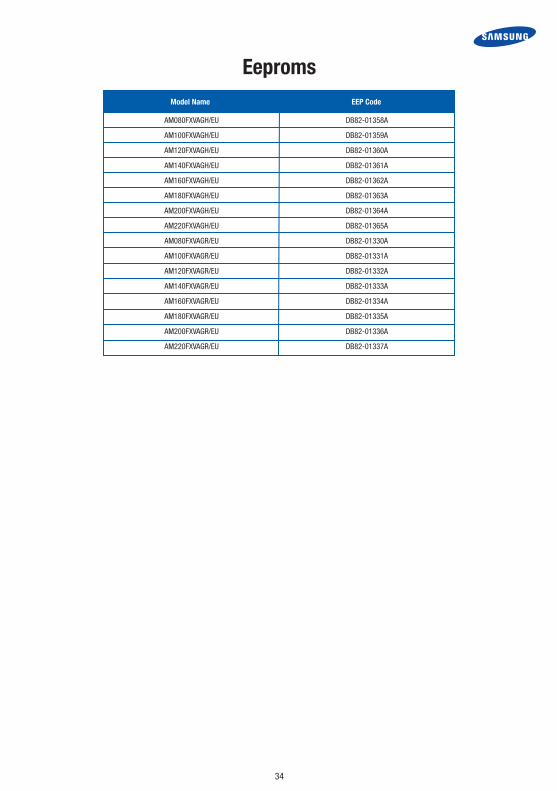
Eeproms
34
AM080FXVAGH/EU DB82-01358A
AM100FXVAGH/EU DB82-01359A
AM120FXVAGH/EU DB82-01360A
AM140FXVAGH/EU DB82-01361A
AM160FXVAGH/EU DB82-01362A
AM180FXVAGH/EU DB82-01363A
AM200FXVAGH/EU DB82-01364A
AM220FXVAGH/EU DB82-01365A
AM080FXVAGR/EU DB82-01330A
AM100FXVAGR/EU DB82-01331A
AM120FXVAGR/EU DB82-01332A
AM140FXVAGR/EU DB82-01333A
AM160FXVAGR/EU DB82-01334A
AM180FXVAGR/EU DB82-01335A
AM200FXVAGR/EU DB82-01336A
AM220FXVAGR/EU DB82-01337A
Model Name EEP Code

23
Thermistor InformationTYPE : 204CT RESISTANCE : 200 at 25°C RESISTANCE TOLERANCE : ±5%
TEMP.(°C) 204CT ( ) TEMP.(°C) 204CT ( ) TEMP.(°C) 204CT ( ) TEMP.(°C) 204CT ( ) TEMP.(°C) 204CT ( )
0 553.5 33 148.3 66 49 99 19.07 128 9.321
1 529.8 34 142.9 67 47.52 100 18.58 129 9.11
2 507.3 35 137.8 68 46.08 101 18.1 130 8.904
3 485.9 36 133 69 44.7 102 17.63 131 8.702
4 465.5 37 128.3 70 43.37 103 17.18 132 8.505
5 446.2 38 123.8 71 42.08 104 16.74 133 8.314
6 427.7 39 119.5 72 40.83 105 16.31 134 8.128
7 410.2 40 115.4 73 39.63 106 15.9 135 7.947
8 393.5 41 111.4 74 38.47 107 15.5 136 7.77
9 377.6 42 107.5 75 37.34 108 15.11 137 7.599
10 362.4 43 103.9 76 36.26 109 14.73 138 7.432
11 347.7 44 100.3 77 35.22 110 17.37 139 7.27
12 333.7 45 96.95 78 34.21 111 14.01 140 7.112
13 320.3 46 93.7 79 33.23 112 13.67 141 6.957
14 307.6 47 90.58 80 32.29 113 13.33 142 6.807
15 295.4 48 87.58 81 31.37 114 13.01 143 6.66
16 283.8 49 84.69 82 30.48 115 12.69 144 6.517
17 272.8 50 81.92 83 29.62 116 12.39 145 6.378
18 262.2 51 79.23 84 28.79 117 12.09 146 3.243
19 252.1 52 76.64 85 27.99 118 11.8 147 3.111
20 242.5 53 74.14 86 27.21 119 11.52 148 5.982
21 233.2 54 71.75 87 26.45 120 11.25 149 5.857
22 224.3 55 69.44 88 25.73 121 10.98 150 5.735
23 215.9 56 67.23 89 25.02 122 10.72 151 5.616
24 207.8 57 65.09 90 24.34 123 10.47 152 5.5
25 200 58 63.04 91 23.68 124 10.23 153 5.386
26 192.5 59 61.06 92 23.03 125 9.993 154 5.276
27 185.3 60 59.16 93 22.41 126 9.763 155 5.168
28 178.5 61 57.3 94 21.81 127 9.539 156 5.063
29 171.9 62 55.52 95 21.23 124 10.23 157 4.961
30 165.7 63 53.79 96 20.66 125 9.993 158 4.861
31 159.6 64 52.14 97 20.12 126 9.763 159 4.764
32 153.8 65 50.54 98 19.59 127 9.539 160 4.669
35

24
Thermistor InformationTYPE : 103AT-1 RESISTANCE : 10 at 25°C B VALUE TOLERANCE : ±2%
TEMP.(°C) 103AT ( ) TEMP.(°C) 103AT ( ) TEMP.(°C) 103AT ( ) TEMP.(°C) 103AT ( ) TEMP.(°C) 103AT ( )
-50 329.5 -17 58.68 16 14.12 49 4.299 82 1.577
-49 310.9 -16 55.97 17 13.58 50 4.16 83 1.533
-48 283.5 -15 53.41 18 13.06 51 4.025 84 1.491
-47 277.2 -14 50.98 19 12.56 52 3.896 85 1.451
-46 262 -13 48.68 20 12.09 53 3.771 86 1.411
-45 247.7 -12 46.5 21 11.63 54 3.651 87 1.373
-44 234.3 -11 44.43 22 11.2 55 3.536 88 1.336
-43 221.7 -10 42.47 23 10.78 56 3.425 89 1.3
-42 209.9 -9 40.57 24 10.38 57 3.318 90 1.266
-41 198.9 -8 38.77 25 10 58 3.215 91 1.232
-40 188.5 -7 37.06 26 9.632 59 3.116 92 1.2
-39 178.5 -6 35.44 27 9.281 60 3.02 93 1.168
-38 169 -5 33.9 28 8.944 61 2.927 94 1.137
-37 160.2 -4 32.44 29 8.622 62 2.838 95 1.108
-36 151.9 -3 31.05 30 8.313 63 2.751 96 1.079
-35 144.1 -2 29.73 31 8.014 64 2.668 97 1.051
-34 136.7 -1 28.48 32 7.728 65 2.589 98 1.024
-33 129.8 0 27.28 33 7.454 66 2.511 99 0.9984
-32 123.3 1 26.13 34 7.192 67 2.436 100 0.9731
-31 117.1 2 25.03 35 6.94 68 2.364 101 0.9484
-30 111.3 3 23.99 36 6.699 69 2.295 102 0.9246
-29 105.7 4 23 37 6.467 70 2.228 103 0.9014
-28 100.5 5 22.05 38 6.245 71 2.163 104 0.8789
-27 95.52 6 21.15 39 6.032 72 2.1 105 0.8572
-26 90.84 7 20.3 40 5.827 73 2.039 106 0.836
-25 86.43 8 19.48 41 5.629 74 1.98 107 0.8155
-24 82.26 9 18.7 42 5.438 75 1.924 108 0.7956
-23 78.33 10 17.96 43 5.255 76 1.869 109 0.7763
-22 74.61 11 17.24 44 5.08 77 1.816 110 0.7578
-21 71.1 12 16.56 45 4.911 78 1.765
-20 67.77 13 15.9 46 4.749 79 1.716
-19 64.57 14 15.28 47 4.593 80 1.668
-18 61.54 15 14.69 48 4.443 81 1.621
36

BLDC Fan Trouble Shooting
37
STEP 1 Check the Voltage
1 After remove the Fan motor connector,
2 Check DC310V on treminals 1 and 3. If Not applied, Change Main PCB
STEP 2 Check voltage
1 Check DC15V terminals 3 and 4
2 If voltage is applied motor is faulty
3 If voltage is not applied, PCB is defective
STEP 3 Check the Power IC & Driver IC defect
1 Check the Power IC defect
Pin1(RED) Pin3(BLK) : Short (0Ω)
à Power IC damaged
2 Check the Driver IC defect
Pin3(BLK) Pin4(WHT) : Short (0Ω) à
à Driver IC damaged
Connector 5 pin & 3 wire
(Red, Yellow, Blue)
Connector 6 pin / 7 pin
& 6 wire
Connector 5 pin & 3 wire
(Red, White, Black)
Connector 3 pin & 3 wire
(Yellow, Orange, Gray)
6 wire
(Yellow, Pink, Blue, Black, Orange, Green)
AC Motor
BLDC motorInternal Control PCB
BLDC motorExternal Control PCB
ACTION
POWERTYPE HALL SENSOR
NOTE
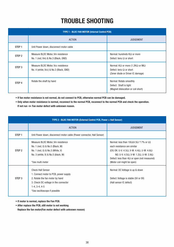
TROUBLE SHOOTING
38
ACTION JUDGEMENT
STEP 1 Unit Power down, disconnect motor cable
STEP 2
Measure BLDC Motor, Vm resistence Normal: hundreds KΩ or more
No. 1 (red, Vm) & No.3 (Black, GND) Defect: tens Ω or short
STEP 3
Measure BLDC Motor, Vcc resistence Normal: KΩ or more (1.2KΩ or MΩ
No. 4 (white, Vcc) & No.3 (Black, GND) Defect: tens Ω or short (Zener diode or Driver IC damage)
STEP 4
Rotate the shaft by hand Normal: Rotate smoothly
Defect: Shaft is tight (Magnet dislocation or coil short)
ACTION JUDGEMENT
STEP 1 Unit Power down, disconnect motor cable (Power connector, Hall Sensor)
Measure BLDC Motor, Vm resistence Normal: less than 10Ω(4.5Ω +- 7% or Ω)
No. 1 (red, U) & No.5 (Black, W) each resistance are similar
STEP 2 No. 1 (red, U) & No.3 (White, V) (EX) OK: U-V: 4.5Ω, V-W: 4.4Ω, U-W: 4.6Ω
No. 3 (white, V) & No.5 (black, W) NG: U-V: 4.5Ω, V-W: 1.2Ω, U-W: 3.9Ω Defect: less than 4Ω or open (not measured) *Use multi meter (Motor coil might be open)
Check Hall Sensor Normal: DC Voltage is up & down
1. Connect motor to PCB, power supply
STEP 3 2. Rotate the fan motor by hand Defect: Voltage is stable (5V or 0V)
3. Check DC voltage in the connector (Hall sensor IC defect)
1-4, 3-4, 4-5
*Use oscilloscope if possible
• If fan motor resistance is not normal, do not connect to PCB, otherwise normal PCB can be damaged.
• Only when motor resistance is normal, reconnect to the normal PCB, reconnect to the normal PCB and check the operation.
If not run –> Fan motor defect with unknown reason.
• If motor is normal, replace the Fan PCB.
• After replace the PCB, still motor is not working
Replace the fan motor(Fan motor defect with unknown reason)
TYPE 1 - BLDC FAN MOTOR (Internal Control PCB)
TYPE 2 - BLDC FAN MOTOR (External Control PCB, Power + Hall Sensor)

TROUBLE SHOOTING
39
ACTION
STEP 1 Power down
STEP 2 Disconnect fan motor connector from IDU PCB
STEP 3 Power on, Check DC Voltage 1 pin DC 310V
2 pi -
3 pin Ground
4 pin DC 15V
5 pin Vsp (0-5V)
6 pin Vg (Feed Back - pulse)
CAUTION HOW TO CHECK
Power supply to indoor unit only PBA #1, #3 pin DC voltage check
Normal: about 280-320V
WHEN PCB CHECK 220 x 1.414 = 310V
Do not run the indoor unit PBA #3, #4 pin DC voltage check
Normal: about 15V
* BE CAREFUL NOT TO GET SHORT
* CHECK BEFORE ERROR OCCUR Run the indoor unit in fan mode and test Motor #3, #5 pin DC voltage check
in advance (within 20 - 30 sec) Normal: about 2-5V or up and down
*While this test Fan error is normal as
fan is diconnected
INTERNAL CONTROL PCB TYPE ONLY
INTERNAL CONTROL PCB TYPE ONLY

REFRIGERANT CHARGING GRAMS
LIQUID LINE + KW INDOOR = TOTAL
40
SIZE OF LIQUID PIPE 6.35 9.52 12.7 15.88 19.05 22.22 25.4 28.58
ADDITIONAL AMOUNT 0.02 0.06 0.125 0.18 0.27 0.35 0.53 0.65
SLIM 1 WAY CASSETTE AM***FN1DEH/EU 0.25 0.25 0.25
SLIM 2 WAY CASSETTE AM***FN2DEH/EU 0.31
GLOBAL 4WAY CASSETTE AM***FN4DEH/EU 0.45 0.45 0.45 0.45 0.57 0.69 0.69
FLOOR STANDING UNIT AM***FNFDEH/EU 0.22 0.32 0.32
ERV PLUS AM***FNKDEH/EU 0.11 0.36
GLOBAL MINI 4WAY CASSETTE AM***FNNDEH/EU 0.29 0.29 0.29 0.37 0.37 0.37
SLIM DUCT AM***FNLDEH/EU 0.24 0.24 0.24 0.24 0.45 0.45 0.42 0.42 0.62 0.62
MSP DUCT-S AM***FNMDEH/EU 0.24 0.24 0.24 0.28 0.28 0.28 0.32 0.54 0.68 0.68
CEILING AM***FNCDEH/EU 0.39 0.39
CONSOLE 0.27 0.27 0.27
NEO FORTE AM***FNTDEH/EU 0.24 0.24 0.24 0.36 0.36
NEO FORTE AM***FNQDEH/EU WITH EEV 0.24 0.24 0.24 0.36 0.36 0.36
HSP DUCT AM***FNHDEH/EH 0.68 0.68 0.68 1.18 1.18
MCU (MCU-S*NEE*N) 0.5
REFRIGERANT CHARGING GRAMS
MODEL /CAPACTIY 2.2 2.8 3.6 4.5 5.6 6 7.1 9 11.2 12.8 14 22 28 500CMH 1000CMH

TS Phone Number 1300 887 660 Option 1for further assistance
Date Printed: March 2016