sampling method for particle measurements of vehicle...
TRANSCRIPT
SAE Paper 2001-01-0219
Sampling method for particle measurements of vehicle exhaust
Pirita Mikkanen and Mikko MoisioDekati Ltd.
Jorma Keskinen, Jyrki Ristimäki and Marko MarjamäkiTampere University of Technology, Department of Physics
Copyright 2000 Society of Automotive Engineers, Inc.
ABSTRACT
This paper describes a new sampling conceptfor particle emission measurements. Thepurpose is to produce repeatable andreproducible conditions for nucleationphenomena. The exhaust is sampled andinstantaneously diluted by inserting a poroustube diluter inside the tailpipe. This is carriedout in order to prevent uncontrolled sampletransformations in sampling lines. Thesampling system was tested in sizedistribution measurement of light duty dieselvehicle. The tests showed a clearly bimodalsize distribution with distinguished nuclei andaccumulation modes.
INTRODUCTION
The legislation on particle matter (PM)emissions from vehicles is conventionallybased on mass measurements. In addition,there is a growing interest for particle sizedistribution measurements. The particlenumber size distribution measurements are acommon practice in the vehicle emissionresearch, even though they are not required bythe current legislation. However, thelegislative limits for the particle emissions arebecoming increasingly strict [e.g. 1], whichemphasises the role of particle samplingmethods.
Recently, it has been argued that reliable andaccurate particulate emission measurementsof vehicles depends more on proper samplingand transport of the sample than onmeasurement instruments themselves. The
vehicle exhaust is a dynamic mixture ofcarbonaceous particles, i.e. soot, volatilehydrocarbons, sulphur compounds, watervapour etc. Uncontrolled dilution andtransport of this mixture may causeunintentional transformations [2,3].Moreover, concentrations of differentcompounds can change the dynamics of themixture. For example, there is evidence thatreducing the concentration of soot particles invehicle exhaust may increase the number ofnucleated particles in measured samples [4].
The condensable hydrocarbons present in thevehicle exhaust may form particles orcondense on existing particles during dilution.Amann and Siegla [5] reported the fraction ofthe hydrocarbons to be 10-30 % of the totalparticle matter in diesel light-duty cars.Moreover, these compounds can condense onsampling lines or diluters and be subsequentlyreleased during episodes of prolonged highexhaust temperature. Maricq et al. [6] foundthe sampling line artifacts overwhelm theexhaust particle matter concentrations for agasoline engine measured after a dieselengine in the same test bench.
In addition to hydrocarbons, soot particles canbe lost in sampling lines by deposition. Thesedeposited particles may re-entrain and causean unexpected coarse particle mode in particlesize distribution [7,8]. The origin of thecoarse particles may be in the exhaust systemof the vehicle or in the sampling lines.
The objective of this study has been toconstruct and test a new sampling system.
The system was designed to producerepeatable and reproducible conditions fornucleation phenomena. The system is basedon simultaneous sampling and dilution of theexhaust gas flow. This method has beenapplied for combustion studies earlier [e.g. 9].This paper describes the design principles ofthe device and discusses reasons for thecompromises in sampling. Finally, a testresult of a vehicle exhaust dilution ispresented.
DESIGN PRINCIPLES ANDDISCUSSION
The purpose of the new dilution method wasto dilute the sample in a manner thatmaximum nucleation of the sulphurcompounds and hydrocarbon vapour isachieved and simultaneously particle losses inthe sampling system are minimised. Duringcontrolled cooling in the diluter, compoundswith tendency to form new ultrafine particlesnucleate. As a consequence, particles existingprior to sampling may be distinguished fromparticles forming during dilution by their size.The nucleated new particles form a nucleimode, which can be defined as smaller than50 nm, and the soot based carbonaceousparticles form an accumulation mode, whichcan be defined as 50-1000 nm.
Kittelson and Abdul-Khalek [10]experimented values to create a highnucleation rate in exhaust sampling. Valuesadapted from their work are shown in Table 1.
Table 1. Variables used in order to maximisenucleation in a sampling system.
Variable Unit ValueDilution ratio - 10-20Residence time s 1 or 1.5Dilution airtemperature
°C 30-50
Relativehumidity
% Controlled
In a porous tube diluter, the dilution air isintroduced at the tip of the sampling probe
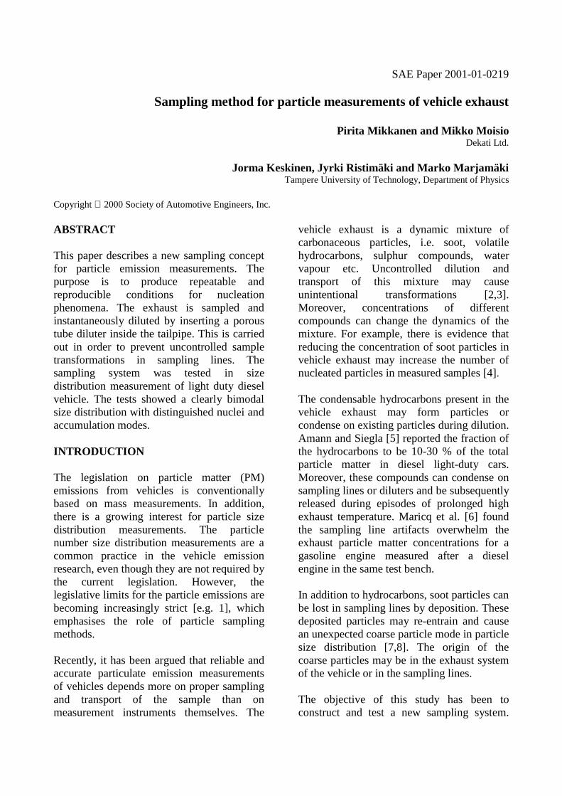
within the tailpipe. The dilution air flowsthrough a porous tube and mixes with thesample gas [11]. Most of the dilution gasflows through the tip of the probe to improvemixing in the probe. The rest of the dilutiongas is introduced through small pores alongthe probe in order to minimise losses insidethe probe. Simultaneously, the dilution air iscooled with an external cooler and withcooling agent jacket around the probe. Thisjacket is designed to maintain the dilution gastemperature below 50°C even during transienttesting. In Figure 1, operation principle of theporous tube diluter is presented. In addition,the cross section of the probe is presentedwith a detail on a heat exchanger surface.
Figure 1. Operational principle of the poroustube diluter (not in scale).
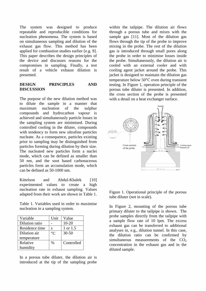
In Figure 2, mounting of the porous tubeprimary diluter to the tailpipe is shown. Theprobe samples directly from the tailpipe witha sample flow rate of 10 lpm. The excessexhaust gas can be transferred to additionalanalyses in, e.g., dilution tunnel. In this case,the dilution ratio can be confirmed bysimultaneous measurements of the CO2
concentration in the exhaust gas and in thediluted sample.
Cooling agentDilution air
Sample
Cross sectionof the probe
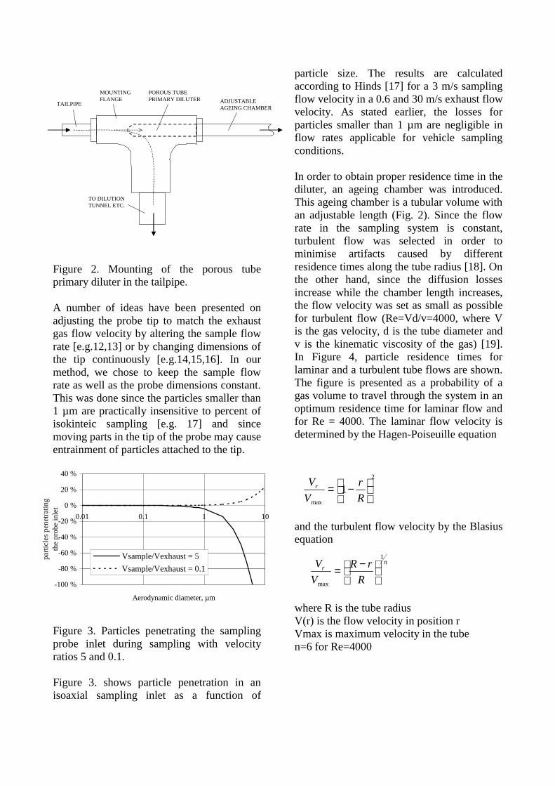
Figure 2. Mounting of the porous tubeprimary diluter in the tailpipe.
A number of ideas have been presented onadjusting the probe tip to match the exhaustgas flow velocity by altering the sample flowrate [e.g.12,13] or by changing dimensions ofthe tip continuously [e.g.14,15,16]. In ourmethod, we chose to keep the sample flowrate as well as the probe dimensions constant.This was done since the particles smaller than1 µm are practically insensitive to percent ofisokinteic sampling [e.g. 17] and sincemoving parts in the tip of the probe may causeentrainment of particles attached to the tip.
Figure 3. Particles penetrating the samplingprobe inlet during sampling with velocityratios 5 and 0.1.
Figure 3. shows particle penetration in anisoaxial sampling inlet as a function of
particle size. The results are calculatedaccording to Hinds [17] for a 3 m/s samplingflow velocity in a 0.6 and 30 m/s exhaust flowvelocity. As stated earlier, the losses forparticles smaller than 1 µm are negligible inflow rates applicable for vehicle samplingconditions.
In order to obtain proper residence time in thediluter, an ageing chamber was introduced.This ageing chamber is a tubular volume withan adjustable length (Fig. 2). Since the flowrate in the sampling system is constant,turbulent flow was selected in order tominimise artifacts caused by differentresidence times along the tube radius [18]. Onthe other hand, since the diffusion lossesincrease while the chamber length increases,the flow velocity was set as small as possiblefor turbulent flow (Re=Vd/v=4000, where Vis the gas velocity, d is the tube diameter andv is the kinematic viscosity of the gas) [19].In Figure 4, particle residence times forlaminar and a turbulent tube flows are shown.The figure is presented as a probability of agas volume to travel through the system in anoptimum residence time for laminar flow andfor Re = 4000. The laminar flow velocity isdetermined by the Hagen-Poiseuille equation
and the turbulent flow velocity by the Blasiusequation
where R is the tube radiusV(r) is the flow velocity in position rVmax is maximum velocity in the tuben=6 for Re=4000
2
max
1
−=
R
r
V
Vr
nr
R
rR
V
V1
max
−=
-100 %
-80 %
-60 %
-40 %
-20 %
0 %
20 %
40 %
0.01 0.1 1 10
Aerodynamic diameter, µm
part
icle
s pe
netr
atin
g th
e pr
obe
inle
t
Vsample/Vexhaust = 5
Vsample/Vexhaust = 0.1
TAILPIPE
TO DILUTIONTUNNEL ETC.
ADJUSTABLEAGEING CHAMBER
MOUNTINGFLANGE
POROUS TUBE PRIMARY DILUTER
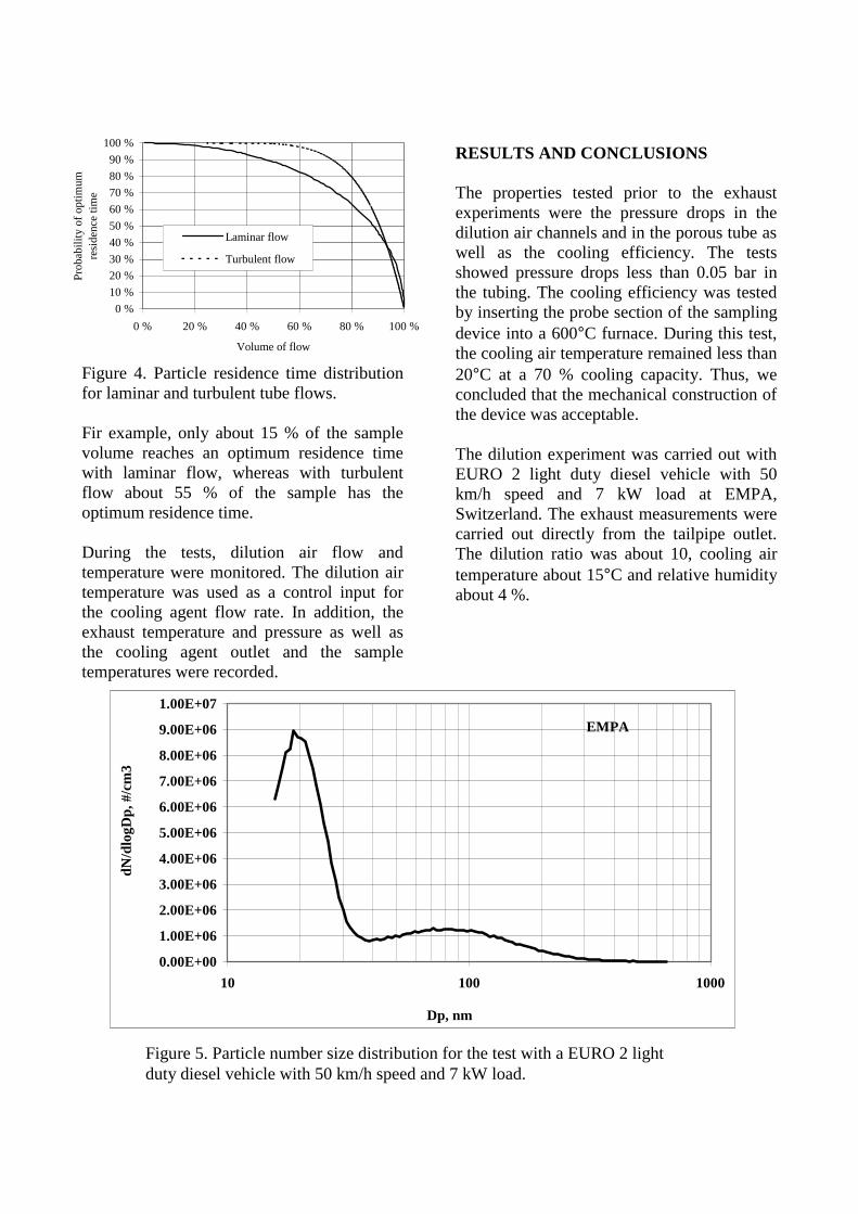
Figure 4. Particle residence time distributionfor laminar and turbulent tube flows.
Fir example, only about 15 % of the samplevolume reaches an optimum residence timewith laminar flow, whereas with turbulentflow about 55 % of the sample has theoptimum residence time.
During the tests, dilution air flow andtemperature were monitored. The dilution airtemperature was used as a control input forthe cooling agent flow rate. In addition, theexhaust temperature and pressure as well asthe cooling agent outlet and the sampletemperatures were recorded.
RESULTS AND CONCLUSIONS
The properties tested prior to the exhaustexperiments were the pressure drops in thedilution air channels and in the porous tube aswell as the cooling efficiency. The testsshowed pressure drops less than 0.05 bar inthe tubing. The cooling efficiency was testedby inserting the probe section of the samplingdevice into a 600°C furnace. During this test,the cooling air temperature remained less than20°C at a 70 % cooling capacity. Thus, weconcluded that the mechanical construction ofthe device was acceptable.
The dilution experiment was carried out withEURO 2 light duty diesel vehicle with 50km/h speed and 7 kW load at EMPA,Switzerland. The exhaust measurements werecarried out directly from the tailpipe outlet.The dilution ratio was about 10, cooling airtemperature about 15°C and relative humidityabout 4 %.
EMPA
0.00E+00
1.00E+06
2.00E+06
3.00E+06
4.00E+06
5.00E+06
6.00E+06
7.00E+06
8.00E+06
9.00E+06
1.00E+07
10 100 1000
Dp, nm
dN/d
logD
p, #
/cm
3
0 %
10 %
20 %
30 %
40 %
50 %
60 %
70 %
80 %
90 %
100 %
0 % 20 % 40 % 60 % 80 % 100 %
Volume of flow
Pro
babi
lity
of o
ptim
um
resi
denc
e tim
e
Laminar flow
Turbulent flow
Figure 5. Particle number size distribution for the test with a EURO 2 lightduty diesel vehicle with 50 km/h speed and 7 kW load.
As depicted in Figure 5. the particle numbersize distribution is clearly bimodal. The nucleimode is clearly distinguished from the sootmode, as set for design criteria. The nucleimode peaks at about 20 nm and the soot modeat about 80 nm. These values correspond tomeasurement results obtained from similarcars in earlier studies at steady state tests.
The question remains, whether the results ofsampling ought to present the exhaustcharacteristics as they exit the tailpipe or tosimulate the atmosphere as the exhaust mixesin the conditions outside the tailpipe.However, with the presented method, theexhaust characteristics could be transformedintentionally.
ACKNOWLEDGEMENTS
The authors would like to thank Dr. MartinMohr and Mr. Urs Mathis from EMPA forproviding the test data. This work wasfinanced by EC project 'Particulates' inGROWTH Programme. The Partner’s in theproject and Professor Kittelson from theUniversity of Minnesota are greatlyacknowledged for sharing their expertise.
REFERENCES
1. Baker, J. A. "Particulate matter regulationand implications for the diesel engine", SAETechnical Paper 981174 (1998)
2. Baumgard, K. J. and Johnson, J. H. “Theeffect of fuel and engine design on dieselexhaust particle size distributions”, SAETechnical Paper 960131 (1996)
3. Abdul-Khalek, I. S.; Kittelson, D. B. andBrear "Diesel exhaust particle size:Measurement issues and trends", SAETechnical Paper 980525 (1998)
4. Brown, J. E.; Clayton, M. J:; Harris, D. B:;King, F. G. Jr. "Comparison of the particlesize distribution of heavy-duty diesel exhaustusing a dilution tailpipe sampler and an in-plume sampler during on-road operation",
Journal of the Air and Waste ManagementAssociation (2000)
5. Amann, C. A.; Siegla, D. C. "Dieselparticulates-what they are and why", AerosolScience and Technology (1982)
6. Maricq, M. M.; Chase, R. E.; Podsiadlik,D. H.; Vogt, R. "Vehicle exhaust particle sizedistributions: A comparison of tailpipe anddilution tunnel measurements" SAE TechnicalPaper 1999-01-1461 (1999)
7. Abu-Quadis, M. and Kittelson, D. B."Experimental and theoretical study ofparticulate re-entrainment from combustionchamber walls of a diesel engine", Process inInstrumentation for Mechanical Engineers(1997)
8. Andrews, G. E.; Clarke, A. J.; Rojas, N. Y.;Gregory, D. and Sale, T. "Diesel particle sizedistribution changes along a practical exhaustsystem during cold start in a passenger carIDI diesel" SAE Technical Paper 2000-01-0514 (2000)
9. Biswas, P. "Measurement of highconcentration and high temperature aerosols"In: Aerosol Measurement: Principles,Techniques and Applications, Eds. Willeke K.and Baron, P. A., Van Nostrand Reinhold,New York (1993)
10. Kittelson, D. and Abdul-Khalek, I."Formation of Nanoparticles during exhaustdilution" EFI Members Conference: 'Fuels,Lubricants, Engines, & Emissions' (1999)
11. Biswas, P.; Li, X. and Pratsinis, S. E."Optical Waveguide Preform Fabrication:Silica Formation and Growth in a HighTemperature Aerosol Reactor", J. of AppliedPhysics, vol 65(6), (1989)
12. US Patent US4649760 “Method andapparatus for controlling flow volume throughan aerosol sampler
13. US Patent US5526685 “Fluid flow ratemeasuring and controlling apparatus andmethod for using SAMS”
14. US Patent US3921458 “Isokineticsampling probe”
15. US Patent US4091835 “Autokineticsampling nozzle”
16. US Patent US4159635 “Isokinetic airsampler”
17. Hinds, W. C. “Aerosol Technology”USA: John Wiley & Sons, Inc. 2nd ed. 483 p.ISBN 0-471-19410-7 (1998)
18. Shapiro, M. and Goldenberg, M."Deposition of glass fiber particles fromturbulent air flow in a pipe", Journal ofAerosol Science (1993)
19. Gomes, M. P. S.; Pui, D. Y. H.; Vincent,J. H. and Liu, B. Y. H. "Convective anddiffusive dispersion of particle in laminar tubeflow: effects on time-dependent concentrationmeasurements", Journal of Aerosol Science(1993)
CONTACT
Dr. Pirita [email protected] Jorma [email protected]