sample - nemetschek groupdownload2cf.nemetschek.net/guides/...sound-sample.pdf · 2d primitive...
TRANSCRIPT

Published by Nemetschek Vectorworks, Inc.
by Kevin Lee Allen | second editionwritten with version 2013
Entertainment Design:Scenery, Lighting, and Sound with Vectorworks Spotlight
SAMPLE

Kevin Lee AllenKevin Lee Allen Design (KLAD)56 Woodlawn AvenueClifton, NJ [email protected]
Copyright© 2012 Kevin Lee AllenAll rights reserved. No part of this book may be reproduced or transmitted in any form by any means, electronic or mechanical, including photocopying, recording, faxing, emailing, posting online, or by any information storage and retrieval system, without prior written permission of the publisher. Published in the United States of America.
TrademarksVectorworks and Renderworks are registered trademarks of Nemetschek Vectorworks, Inc., in the United States and other countires. Windows is a registered trademark of Microsoft Corporation in the United States and other countries. Macintosh is a trademark of Apple Computer, Inc., registered in the United States and other countries. Adobe, Acrobat, and Reader are registered trademarks of Adobe Systems in the United States and other countries.
Notice of LiabilityThe information in this book is distributed on an “as is” basis, without warranty. While every precaution has been taken in the preparation of this book, neither the author nor Nemetschek Vectorworks, Inc., shall have any liability to any person or entity with respect to any loss or damage caused or alleged to be caused directly or indirectly by the information contained in this book or by the computer software described in it.
For more Vectorworks training information or to purchase more copies of this book, please visit www.vectorworks.net/training, or call us at (410) 290-5114.
Copyright 2012 Kevin Lee Allen. It is unlawful to copy this book in any manner.
SAMPLE

©2012 Kevin Lee Allan | Contents i
Table of Contents
Introduction: How to Use This Book ............................................ xiiiBefore You Begin ....................................................................................................................xivThe Vectorworks Environment ................................................................................................xivSome General Rules and Thoughts ....................................................................................... xv
Application Overview ......................................................................1The Vectorworks Working Environment ...................................................................................1Palettes .....................................................................................................................................2
Basic Tool Set ......................................................................................................................2Tool Sets .............................................................................................................................3Attributes .............................................................................................................................3Snapping/Constraints ..........................................................................................................4SmartCursor ........................................................................................................................4Smart Points ........................................................................................................................4
Working Planes ........................................................................................................................4Object Information Palette (OIP) ..............................................................................................5Resource Browser ....................................................................................................................5Navigation .................................................................................................................................6Visualization .............................................................................................................................6Document Window ...................................................................................................................6
View Bar ..............................................................................................................................6Tool Bar ...............................................................................................................................7Quick Preferences ...............................................................................................................8Message Bar .......................................................................................................................8Moving the View ..................................................................................................................8Zooming ..............................................................................................................................9
Modeling Overview (Quick Start) ..................................................11Exercise One .......................................................................................................................... 11 Creating and Working with Viewports .....................................................................................14Dimensioning in Viewports .....................................................................................................15Exercise Two ..........................................................................................................................18
The Vectorworks Workspaces .....................................................21
SAMPLE

ii Contents | ©2012 Kevin Lee Allen
Document Organization and Stationery ........................................23Vectorworks Preferences ........................................................................................................23
Edit ....................................................................................................................................23Display ..............................................................................................................................23Session .............................................................................................................................243D ......................................................................................................................................24Autosave ...........................................................................................................................24Interactive ..........................................................................................................................25User Folders ......................................................................................................................25
Quick Preferences ..................................................................................................................26Document Setup .....................................................................................................................26Drawing/Document Organization ............................................................................................26
Classes .............................................................................................................................27Design Layers ...................................................................................................................27Unified View ......................................................................................................................29Viewing and Working with Multiple Design Layers ............................................................29Sheet Layers .....................................................................................................................29Saved Views ......................................................................................................................29Line Weight .......................................................................................................................29Default Font Settings .........................................................................................................30Document Preferences and Settings.................................................................................30
Spotlight Preferences .............................................................................................................31Default Scale ..........................................................................................................................33Snapping Preferences ............................................................................................................33Fonts .......................................................................................................................................35Template or Stationery Files ...................................................................................................36
Modeling the Booth Theatre ........................................... 37The Layer Plane and the Screen Plane ..................................................................................372D Primitive Tools ...................................................................................................................37
Rectangle ..........................................................................................................................38Circle and Oval ..................................................................................................................39Regular Polygon ................................................................................................................39Polygon and Polyline .........................................................................................................39Triangle .............................................................................................................................39
2D Modifying Tools .................................................................................................................39Reshape ............................................................................................................................39Offset .................................................................................................................................40Fillet and Chamfer .............................................................................................................40
SAMPLE
©2012 Kevin Lee Allan | Contents iii
Locus Points ......................................................................................................................41Clip Tool .............................................................................................................................41
2D Commands ........................................................................................................................41Clip ....................................................................................................................................41Add ....................................................................................................................................41Combine into Surface ........................................................................................................42Intersect Surface ...............................................................................................................42
3D Commands ........................................................................................................................42Add Solids .........................................................................................................................42Subtract Solids ..................................................................................................................42Intersect Solids ..................................................................................................................42Section Solids ...................................................................................................................42Extrude ..............................................................................................................................42Sweep ...............................................................................................................................43Extrude Along Path ...........................................................................................................43Multiple Extrude ................................................................................................................44Chain Extrude ...................................................................................................................44
Manipulating 2D and 3D Objects ............................................................................................44Align/Distribute ..................................................................................................................44Grouping ...........................................................................................................................44Move .................................................................................................................................44Duplicate Array ..................................................................................................................44Move by Points ..................................................................................................................45Mirror .................................................................................................................................45Rotate ................................................................................................................................45Rotate 3D ..........................................................................................................................45Scale Objects ....................................................................................................................45
Using the Tools and Commands .............................................................................................46Classes and Line Types .........................................................................................................47The Soft Goods Tool ...............................................................................................................50Creating an Auto-Hybrid Object ..............................................................................................52Making the Symbol .................................................................................................................53
Sidebar: Creating the End Seat Symbol .......................................57
Understanding Symbols ...............................................................59Symbol Geometry ...................................................................................................................59
2D Symbols .......................................................................................................................593D Symbols .......................................................................................................................59Hybrid Symbols .................................................................................................................59
SAMPLE

iv Contents | ©2012 Kevin Lee Allen
Inserting Symbols ...................................................................................................................60Creating Symbols ...................................................................................................................60Symbol Types .........................................................................................................................61
Red Symbols .....................................................................................................................61Blue Symbols ....................................................................................................................61Black Symbols ...................................................................................................................61Green Symbols .................................................................................................................61
Modifying Symbols .................................................................................................................61Editing Symbols ......................................................................................................................61Symbol Referencing ...............................................................................................................62Symbols and Database Information .......................................................................................62Application Resources ............................................................................................................63
Creating Figure Symbols ..............................................................65
Creating Image Prop Figure Symbols ..........................................69
Using the Human Figure Tool .......................................................73
Creating Solomonic Columns .......................................................77Creating a Seamless Texture .................................................................................................80Classing the Column ..............................................................................................................81Finishing the Model; Base and Capital ...................................................................................82
NURBS and Advanced Modeling Techniques ..............................85NURBS Tools ..........................................................................................................................85NURBS Commands ................................................................................................................85Fillet or Chamfer Edge Tools ..................................................................................................86Loft Surface Tool .....................................................................................................................86Extract Tool .............................................................................................................................87Revolve with Rail Command ..................................................................................................87Solid Shell Tool .......................................................................................................................88Create Drape Surface Command ...........................................................................................88
The Show Deck ............................................................................91
SAMPLE
©2012 Kevin Lee Allan | Contents v
Layer Backgrounds and Textures .................................................99Layer Backgrounds .................................................................................................................99Textures ................................................................................................................................101Mapping ................................................................................................................................102
Procedural Textures ........................................................................................................102Image-Based Textures ....................................................................................................102
Shaders ................................................................................................................................102The Color Shader ............................................................................................................102Reflectivity .......................................................................................................................104Transparency ..................................................................................................................106Image Mask .....................................................................................................................106Bump ...............................................................................................................................107
Decals ...................................................................................................................................108Attribute Mapping Tool ..........................................................................................................108Image Props .........................................................................................................................109
Rotate to View ................................................................................................................. 110Crossed Planes ............................................................................................................... 111Red Image Props ............................................................................................................ 111Constant Reflectivity ....................................................................................................... 111Create Symbol ................................................................................................................ 111
Horizons ............................................................................................................................... 111
The Show Portal .........................................................................113Extrude Along Path ............................................................................................................... 116
The Central Unit .........................................................................119
Creating a Custom Title Block ....................................................125Text Styles ............................................................................................................................126Save as Symbol ....................................................................................................................128Creating Record Formats .....................................................................................................128Attaching Record Formats to the Title Block ........................................................................129Linking Text to Record Formats ............................................................................................129
Putting it all Together, and Then Some .......................................131Using the Soft Goods Object Tool ........................................................................................132Using the LED Screen Tool ..................................................................................................133Stage Composition ...............................................................................................................135
SAMPLE

vi Contents | ©2012 Kevin Lee Allen
Using the Renderworks Camera Tool ...................................................................................135Using Cameras to Check Sight Lines ...................................................................................136Creating Animations .............................................................................................................136
AnimationWorks ..............................................................................................................137Augmented Reality ..........................................................................................................137
Creating a White Model and Other Rendering Options ..............139
Developing the Lighting Design ..................................................143Renderworks Backgrounds ..................................................................................................143Lighting in the 3D World .......................................................................................................144
Lighting Commands ........................................................................................................144Set Lighting Options ........................................................................................................144Light Tools .......................................................................................................................145Directional Light Tool .......................................................................................................145Spot Light ........................................................................................................................146Point Light .......................................................................................................................148Line Lights and Area Lights .............................................................................................148IES Files and Custom Lights ...........................................................................................148
Lighting the Scene ................................................................................................................148
A Basic 3D Lighting Set-Up ........................................................153
Sidebar: Color Libraries via the Attributes Palette ......................155
Preparing to Draw the Light Plot .................................................157Adding Resources ................................................................................................................157Spotlight Preferences ...........................................................................................................159Label Legends ......................................................................................................................161Focus Point Objects .............................................................................................................163
Other Ways to Focus Lights and Create Focus Points ...................................................164Lighting Positions .................................................................................................................165
Creating Lighting Positions .............................................................................................165Trusses .................................................................................................................................166
Audio Tools: Designing the Sound System .................. 169 The Speaker Array Tool ........................................................................................................170
SAMPLE

©2012 Kevin Lee Allan | Contents vii
Interactive Data Exchange with Lightwright 5 .............................173Transferring Data to and from Lightwright ............................................................................173
Linking to the XML File in Lightwright ..............................................................................174The Focus Data Field in Lightwright ................................................................................174Best Practices with Lightwright........................................................................................175Vectorworks Reports and Schedules ..............................................................................176
Designing the Lighting/Drawing the Light Plot ............................177Inserting/Modifying Instruments ............................................................................................178
Adding Gobos .................................................................................................................179Coloring Lights ................................................................................................................180Aligning Instruments ........................................................................................................181
Managing the OIP .................................................................................................................181Refreshing Instruments ........................................................................................................183Perform a Complete Export on Exit ......................................................................................183
Sidebar: Creating the Boom Position Symbol ............................185
Visualizing the Designs ..............................................................187Create Plot and Model View .................................................................................................187Editing Lights ........................................................................................................................188Adding Accessories ..............................................................................................................190Photometrics/PhotoGrid .......................................................................................................191Basic Scripting ......................................................................................................................192Custom Lighting Symbols .....................................................................................................192Align and Distribute Tool .......................................................................................................192Ganging Tool ........................................................................................................................193ESP Vision ............................................................................................................................193Animate Scenes ...................................................................................................................194
Creating the Production Documents ...........................................197Design Layers .......................................................................................................................197The Sheet Border Tool ..........................................................................................................198Create Sheet List ..................................................................................................................199Adding the Command to your Workspace ............................................................................200Using Data Records in Working Drawings ...........................................................................201Creating a Camera Viewport ................................................................................................201The Drawing Label Tool ........................................................................................................203Creating and Annotating the Ground Plan ............................................................................204
SAMPLE

viii Contents | ©2012 Kevin Lee Allen
Using the Scale Bar Tool ......................................................................................................204Creating the Stage Sections .................................................................................................205Cropping a Viewport .............................................................................................................206Class Overrides ....................................................................................................................206Annotate the Section Viewport .............................................................................................206Create the Stage Left Section ..............................................................................................207Creating the Light Plot Viewport ...........................................................................................207Creating the Key to Instrumentation .....................................................................................208Creating the Boom Plot ........................................................................................................209Creating the Scenic Elevations .............................................................................................209The Callout Tool ....................................................................................................................210Adding Hyperlinks .................................................................................................................210
Help Files and Resources ..........................................................213Vectorworks Service Select ..................................................................................................213The Help Menu .....................................................................................................................213
The Help Application .......................................................................................................213Additional Help .....................................................................................................................213Application Resources ..........................................................................................................214
Acknowledgements ....................................................................215
Links ...........................................................................................216Nemetschek Vectorworks .....................................................................................................216Light Plot Deconstructed ......................................................................................................216Training .................................................................................................................................216Applications ..........................................................................................................................216Vectorworks Plug-ins ............................................................................................................217Spotlight Plug-ins ..................................................................................................................217Online Communities .............................................................................................................217Blogs .....................................................................................................................................217
About the Author .........................................................................218
SAMPLE
©2012 Kevin Lee Allen | Entertainment and Lighting Design with Vectorworks Spotlight 37
Modeling the Booth Theatre
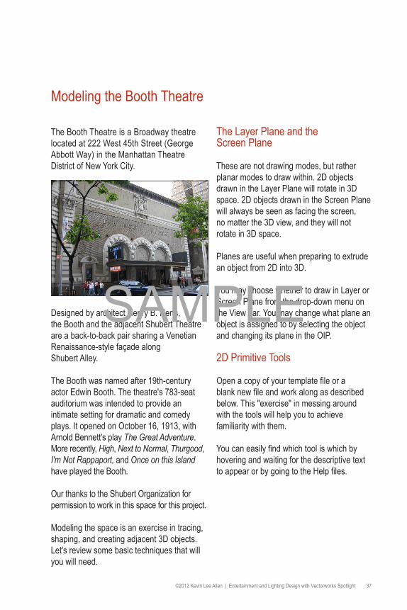
The Booth Theatre is a Broadway theatre located at 222 West 45th Street (George Abbott Way) in the Manhattan Theatre District of New York City.
Designed by architect Henry B. Herts, the Booth and the adjacent Shubert Theatre are a back-to-back pair sharing a Venetian Renaissance-style façade along Shubert Alley.
The Booth was named after 19th-century actor Edwin Booth. The theatre's 783-seat auditorium was intended to provide an intimate setting for dramatic and comedy plays. It opened on October 16, 1913, with Arnold Bennett's play The Great Adventure. More recently, High, Next to Normal, Thurgood, I'm Not Rappaport, and Once on this Island have played the Booth.
Our thanks to the Shubert Organization for permission to work in this space for this project.
Modeling the space is an exercise in tracing, shaping, and creating adjacent 3D objects. Let's review some basic techniques that will you will need.
The Layer Plane and the Screen Plane
These are not drawing modes, but rather planar modes to draw within. 2D objects drawn in the Layer Plane will rotate in 3D space. 2D objects drawn in the Screen Plane will always be seen as facing the screen, no matter the 3D view, and they will not rotate in 3D space.
Planes are useful when preparing to extrude an object from 2D into 3D.
You may choose whether to draw in Layer or Screen Plane from the drop-down menu on the View bar. You may change what plane an object is assigned to by selecting the object and changing its plane in the OIP.
2D Primitive Tools
Open a copy of your template file or a blank new file and work along as described below. This "exercise" in messing around with the tools will help you to achieve familiarity with them.
You can easily find which tool is which by hovering and waiting for the descriptive text to appear or by going to the Help files.
SAMPLE

38 Entertainment and Lighting Design with Vectorworks Spotlight | ©2012 Kevin Lee Allen
RectangleAlthough we've already used the Rectangle tool, we are going to begin by selecting the Rectangle tool. Notice the options in the Tool bar change when a tool is selected. Each mode or option available in the Tool bar offers a different way of drawing. By hovering over the mode icons, you will see descriptive text appearing for each mode. Text in the Tool bar also describes the active option.
Typically when freehand drawing, objects can be constrained when you press a key(s). For example, you can constrain a rectangle to a square by pressing the Shift key. You can constrain a rectangle to the Golden Ratio by pressing the Shift and Command keys simultaneously while dragging. With the Shift key pressed, an oval can be constrained to a circle.
These options will vary with the tool selected. As you explore the application, try every mode available in each case.
You can simply begin to draw by clicking and dragging. As soon as you begin to draw, you will note the appearance of the Floating Data bar (FDB). Hit the Tab key to select the first field in the FDB and enter a specific dimension. Then tab to the next field, repeat, and click with the mouse. You have created a specifically sized shape!
Draw a few rectangles, and note the highlight color when you hover over a shape and the change in color when you select a shape. You can select multiple objects by pressing and holding the Shift key or doing a marquee selection (click and drag with the 2D Selection tool). To Marquee select, simply drag around the entire object. You can also Marquee select by pressing the Option key and selecting any object you partially touch.
Select an existing rectangle and note that you can move it or resize it interactively with the mouse. Also note that you can change its size and location in the OIP.
Draw a rectangle in an isometric view with the Push/Pull mode activated in the Tool bar. As soon as you finish drawing, move the mouse over the rectangle and notice that it becomes highlighted. Click and drag to extrude the rectangle. The Push/Pull mode option is available for all of the 2D primitive drawing tools.
Select the Rectangle tool and hover the cursor near another rectangle. Note the SmartCursor hints and alignments that are indicated.
Align with a corner, indicated by the red extension line, and hit the T key to lock in that alignment.
SAMPLE

©2012 Kevin Lee Allen | Entertainment and Lighting Design with Vectorworks Spotlight 39
Try this again. When hovering near a snap point, hit the Z key to enable the Snap Loupe, which allows you to zoom in close until you click the mouse. You can also use the snap loupe when you want to finish drawing a shape, if aligning to another point.
Circle and OvalNotice two similar tools, the Circle and the Oval. Select the Oval tool, and notice the different options in the Tool bar. Draw a few ovals using the different options, some freehand, some with absolute positioning, and then with the FDB.
Notice the Circle by 3 Points option. This option also appears in Arcs and Curved Walls and is very useful in tracing curves and in designing the right size circle or arc.
Regular PolygonLike the Circle and Rectangles, the Regular Polygon allows you to make simple multi-sided objects.
Polygon and PolylineThese tools are for freehand drawing and for intelligent tracing with the SmartCursor. The Polygon has only straight lines, but the Polyline tool allows you to introduce curves. Consider tracing a scanned drawing or placing locus points. You can also use the 2D Line tools and absolute positioning to create a set of guides. Then you can connect the dots with the Polygon tool. Press the U key when drawing with the Polyline tool to switch modes on the fly. This key command generally works with every tool option.
Note that the Polyline tool introduces a preferences option in the Mode bar and six different modes for drawing, including very precise arcs and curves. You can switch
modes in the midst of drawing by reaching into the Mode bar or pressing the U key while working.
TriangleThe Triangle tool is located under the 2D Polygon tool. Click on the 2D Polygon tool icon and hold. The Triangle tool will then appear for you to select. Note that this tool has three different modes of operation available in the Mode bar.
2D Modifying Tools
ReshapeThe Reshape tool allows for the editing of polygons. If you want to edit a rectangle into a shape other than a rectangle, you must first convert the rectangle into a polygon. Select the rectangle and go to Modify>Convert>Convert to Polygon.
The Reshape tool has several modes and options. Reshaping allows users to move points, add points (between existing points), subtract points, or convert points from corners to curves and vice versa.
Let’s assume that you have not been able to make the shape that you want. Draw a rectangle. A rectangle is not a polygon, but
SAMPLE

40 Entertainment and Lighting Design with Vectorworks Spotlight | ©2012 Kevin Lee Allen
you can make a rectangle into a polygon by Adding or Clipping. In this case, we will select the rectangle and go to Modify>Convert>Convert To Polygon.
Select the Reshape tool from the Basic Tool set and edit. You can also double-click the polygon, and the 2D Reshape tool will self-select. Let’s look at the options:
• Move points• Convert points• Add a point• Subtract a point• Hide or show edges
Note: When you select Add or Convert, other options become available. Note also the options for selecting points. This is a very robust tool and is very useful for creating sweeping curves.
Your rectangle now shows eight points or, more precisely, four points on the corners and four midpoints. Experiment with the tool: Try these things and then undo so you always return to the basic rectangle. Select the first option on the left, Move Polygon Handles mode. Grab a corner and move it around. Undo. Select the Delete Vertex mode, and delete one of the corners so that you have a rectangle. Undo. Select Add Vertex, and be sure that you have the Corner Vertex option selected. Note that you can add and manipulate points only at a midpoint. Select the Change Vertex mode and then select Bezier Curve. Click on a corner and observe the curve. Manipulate this curve with the Move mode. On another corner, convert the corner point to a Cubic Spine Point. Manipulate the curve and compare how they differ.
OffsetThe Offset tool allows you to quickly duplicate a surface inside or outside of an object. Select the tool and go to the tool preferences in the Tool bar. If you have just drawn a complex shape and will use that shape as a platform, you will need to allow for the thickness of the reveal and/or the structure. Simply offset the shape.
Fillet and ChamferThe Fillet and Chamfer tools are very similar. There are 2D and 3D versions for these tools. The 2D tools are in the Basic Tool set and the 3D are in the 3D Modeling Tool set. You'll recall that we have done some basic work with the 3D tools in our first exercise. These terms are generally used in cabinetry and millwork. In each case, these tools trim the corner off of a polygon. A chamfer is a straight line cut and a fillet makes a rounded corner. In each case, select the tool and trim the edge of a polygon. First select a mode. They each have the same three modes. The first Chamfer or Fillet option adds the detail, the second trims the lines of the polygon to the detail, and the third trims the original shape to the new detail and deletes the lines left when using the second mode.
Select the tools, set your preferences and mode, and then hover over the edge of a polygon. If eligible for Chamfer/Fillet, the edge will be highlighted. Click and drag to an adjacent edge, and it too will be highlighted. Click to execute.
SAMPLE

©2012 Kevin Lee Allen | Entertainment and Lighting Design with Vectorworks Spotlight 41
This object has two Chamfers and a Fillet.
Locus PointsLocus Points/Datum provide guides for drawing and reference points as needed. There is a 2D Locus and a 3D Locus tool, located in the respective tool sets.
Clip ToolThe Clip tool offers a number of options and modes for removing pieces of 2D forms.
The object below has been clipped using each of the three modes.
2D Commands
ClipModify>Clip Surface is used to subtract one shape from another. First, draw one primitive shape over a larger shape. Select both and
go to the command. Only the top object will remain selected. Delete that object, and you will notice a hole in the bottom object.
AddModify>Add Surface combines two objects into one. Draw two overlapping objects, select both, and invoke the command. You will be left with one new object.
SAMPLE

42 Entertainment and Lighting Design with Vectorworks Spotlight | ©2012 Kevin Lee Allen
Combine into SurfaceThe Combine into Surface command forms a new object from a group of objects. The objects must intersect and form a closed polygon. Depending on objects selected and the location of the mouse click, you can create several different polygons from the same set of objects.
Draw two or more overlapping objects, select them all, and go to Modify>Combine into Surface. The cursor will change into a paint bucket. Place the paint bucket inside the area of the polygon you wish to keep and click. A single polygon object is created from the selected objects. The new object uses the current attributes.
Intersect SurfaceCreate two overlapping objects and select both. Then, go to Modify>Intersect Surfaces and note that the remaining shape is the shape of the area where the two objects once overlapped.
3D Commands
Add SolidsLike the 2D Add Surface command, the 3D Add Solids command (Model>Add Solids) combines two or more overlapping and selected 3D objects into one larger object. Once joined, the solids can be edited by double-clicking on the combined object.
Subtract SolidsAgain, similar to the 2D Clip Surface command, the Model>Subtract Solids command subtracts one or more 3D objects from another. When multiple objects are selected and the command enacted, a dialog will appear that allows you to choose which object will remain and be modified.
Intersect Solids
Model>Intersect Solids creates an object from the overlapping areas of two other solids.
Section SolidsSimilar to the Subtract Solids command, Model>Section Solids also allows the manipulation of 3D objects using larger NURBS objects.
ExtrudeMost of your modeling can be most quickly achieved using the Push/Pull tool and the Floating Data bar. However, there are some occasions where the Extrude command will be more efficient.
Draw and modify any primitive or primitives with the tools we have just discussed. Let’s make this shape into a 3D object. With the object selected, go to Model>Extrude (Command + E or Ctrl + E), enter a number in the Extrusion field, and click OK. Remember, if you're drawing in a file based on your template, you'll need to enter a number in scale. If you're working on a new blank file, the scale will be 1:1, and you will want the size to be smaller.
SAMPLE