sample manuscript showing specifications and style€¦ · web viewwind turbines are classified...
TRANSCRIPT

Proceedings of the 2nd Thermal and Fluid Engineering Conference, TFEC20174th International Workshop on Heat Transfer, IWHT2017
April 2-5, 2017, Las Vegas, NV, USA
TFEC-IWHT2017-17438
TITLE: A NOVEL DESIGN FOR VERTICAL AXIS WIND TURBINE
Reza Ghodsi1*, Luz Amaya-Bower1
1Central Connecticut State University, New Britain, CT, USA
ABSTRACT
In this study a new design for a Vertical Axis Wind Turbine is presented. First, four different blade designs were developed and compared initially using Computational Fluid Dynamics (CFD). A two-dimensional transient model was created in Fluent using dynamic mesh in order to evaluate the performance of the turbine at different wind speeds. The performance criterion is based on higher blade speed and lower drag coefficient. Accordingly, a blade design was chosen and a prototype was built. This prototype was tested in a wind tunnel to evaluate the power generated by the turbine at different wind speeds. The turbine was connected to a generator in order to obtain a relationship between wind speed and power. The turbine produces high torque and runs very quiet. There is no flickering effect and is safe for birds. The outcomes of this study prove that the new blade design is an effective alternative for the Vertical Axis Wind Turbine.
KEY WORDS: Vertical Axis Wind Turbine (VAWT), Computational Fluid Dynamics (CFD), Sustainable Energy, Novel Design
1. INTRODUCTION
As an important source of sustainable and renewable energy, wind power can be used to harvest electricity via wind turbines in the so-called wind farms in onshore and offshore settings. Nowadays, the pollution and hazards of consuming fossil fuel are obvious globally, and sustainable energy technologies are encouraged all over the world. However, humans are still far away from using all the wind power that nature provides. REN21 is an international non-profit association and is based at the United Nations Environment Programme (UNEP) in Paris, France. Every year this association publishes valuable reports for the renewable energy global status [1]. Based on their 2016 Key Finding Report, 433 Gigawatts of electricity were produced in the world in year 2015 and this was mainly from 24 countries. By the end of 2015, still 76.3% of the global electricity production was from non-renewable energy sources. Hence, there is much more room for sustainable energies and wind turbines. Wind turbines that can be built and maintained easier and cheaper and are less complex technologically from small to large sizes could be the solution to the global environment crisis.
Wind turbines are classified in two major groups based on the axis of rotation of their blades, namely Horizontal Axis Wind Turbine (HAWT) that produce relatively low torque and Vertical Axis Wind Turbine (VAWT) which produces higher torque. However, since HAWT has a high coefficient of performance, they are more common than VAWT. However, HAWT are more complex technologically and more expensive. Thus, VAWT might be a better option in some cases such as for smaller applications by general public and countries with weaker economies. Wind turbines are built for small to very large applications. Even for small applications, several small size HAWT are available and sold in the market such as the wind turbines sold by Home Depot [2]. However, they are not yet very common globally. The objective of the research at hand is to design a novel and simple VAWT for smaller applications with an acceptable efficiency.
*Corresponding Author: [email protected]
1

TFEC-IWHT2017-17438
A variety of different designs for VAWT have been proposed in the past. Thousands of years ago, Persians used VAWT for milling grain. In 1926, Georges Darrieus invented a new design for power generation [3]. One of the largest turbines ever built is the Éole Darrieus north of Quebec City, Canada which has a 100 ton rotor. [3].The other famous VAWT is the Savonius design with straight half-drum shape blades. One such turbine is installed in the UK [4].
In both Darrieus and Savonius designs as well as other available designs of VAWT, wind is blowing on both the left and right sides of the turbine blades. Thus, only one side has a positive force while the other side creates a negative force reducing the efficiency of the VAWT. In some other designs, researchers tried to lessen the adverse effect of this negative force. One such design is by Paul Cooper and Oliver Kennedy from University of Wollonggong, Australia. They built a three symmetrical blade VAWT where the position of the blades are adjusted based on the wind direction dynamically on the run [3]. Other designs known as Giromill [5], Zephyr [6], and Axial Flux [7] are discussed in the literature, and in all of these designs all blades face the wind simultaneously. Hence, the efficiency of the turbine reduces due to the negative force on the blades which move against the wind. However, Sankar and Morris elaborate on advantages of VAWT even though the efficiency is lower than HAWT [8]. Some of these advantages are that VAWT is easier to build and maintain, it is technologically less demanding, and it can be used in less advanced countries easily.
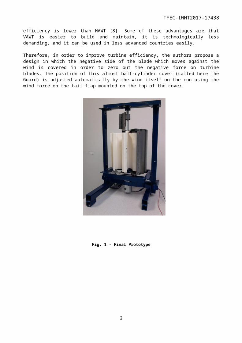
Therefore, in order to improve turbine efficiency, the authors propose a design in which the negative side of the blade which moves against the wind is covered in order to zero out the negative force on turbine blades. The position of this almost half-cylinder cover (called here the Guard) is adjusted automatically by the wind itself on the run using the wind force on the tail flap mounted on the top of the cover.
Fig. 1 - Final Prototype
2
TFEC-IWHT2017-17438
2. COMPUTATIONAL FLUID DYNAMICS
2.1 Blade Design
Four different designs were developed for this study. In all the designs, there are eight blades with a span of 1-m and a 50-mm thickness. The main difference between the designs is the end section of each, which consist of semi-circles of 2 different radii, with and without fillets to remove the sharp edges. In addition, all the designs have the same guard which covers 185° of the blades to ensure that the blades rotate in a clockwise direction. Fig. 1 shows the dimensions for the cross-section of the four designs, including the guard. All the dimensions presented are in millimeters.
Model 1 Model 2
Model 3 Model 4
Fig. 2 - Blade Design Dimensions
2.2 Mesh and Simulation Setup
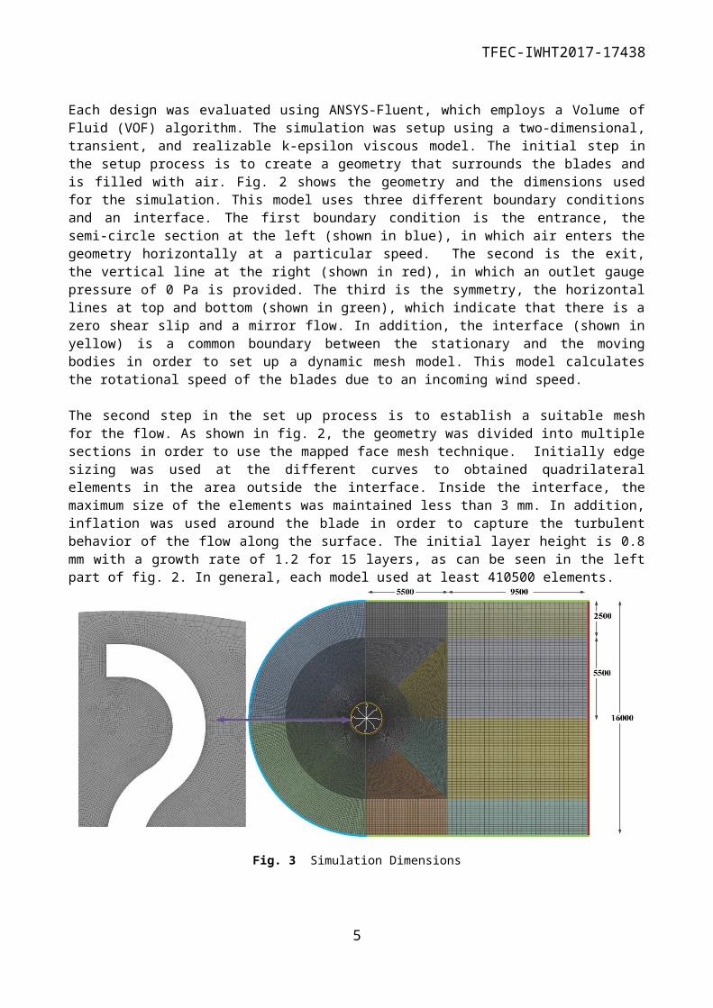
Each design was evaluated using ANSYS-Fluent, which employs a Volume of Fluid (VOF) algorithm. The simulation was setup using a two-dimensional, transient, and realizable k-epsilon viscous model. The initial step in the setup process is to create a geometry that surrounds the blades and is filled with air. Fig. 2 shows the geometry and the dimensions used for the simulation. This model uses three different boundary conditions and an interface. The first boundary condition is the entrance, the semi-circle section at the left
3

TFEC-IWHT2017-17438
(shown in blue), in which air enters the geometry horizontally at a particular speed. The second is the exit, the vertical line at the right (shown in red), in which an outlet gauge pressure of 0 Pa is provided. The third is the symmetry, the horizontal lines at top and bottom (shown in green), which indicate that there is a zero shear slip and a mirror flow. In addition, the interface (shown in yellow) is a common boundary between the stationary and the moving bodies in order to set up a dynamic mesh model. This model calculates the rotational speed of the blades due to an incoming wind speed.
The second step in the set up process is to establish a suitable mesh for the flow. As shown in fig. 2, the geometry was divided into multiple sections in order to use the mapped face mesh technique. Initially edge sizing was used at the different curves to obtained quadrilateral elements in the area outside the interface. Inside the interface, the maximum size of the elements was maintained less than 3 mm. In addition, inflation was used around the blade in order to capture the turbulent behavior of the flow along the surface. The initial layer height is 0.8 mm with a growth rate of 1.2 for 15 layers, as can be seen in the left part of fig. 2. In general, each model used at least 410500 elements.
Fig. 3 Simulation Dimensions
2.3 Simulation Results
The four different blade designs were compared by running cases two initial wind speeds 6 and 24 m/s. The performance criterion is based on higher blade speed and lower drag coefficient. Table 1 provides a summary of the final results for the two cases of each model. Looking at the results, it is noted that the blade geometry with higher radii has a much higher speed and lower drag coefficient. Therefore models 1 and 3 had better values than models 2 and 4. In addition, removing the sharp edges from the geometry improved the overall performance of the design. Therefore, it was determined that Model 3 was the most efficient between the 4 models, since it provided the highest value of blade speed and well as the lowest value for the drag coefficient.
Table 1 - Model ComparisonModel and
Wind Speed (m/s)
Model 1 Model 2 Model 3 Model 4
6 24 6 24 6 24 6 24
Blade Rotational Speed x 103
(RPM)
78 106 28 71 79 111 32 86
Blade Average 0.42 0.71 0.50 0.68 0.39 0.66 0.45 0.69
4
TFEC-IWHT2017-17438
Drag Coefficient
3. PROTOTYPE CONSTRUCTION
3.1 Blade Prototype
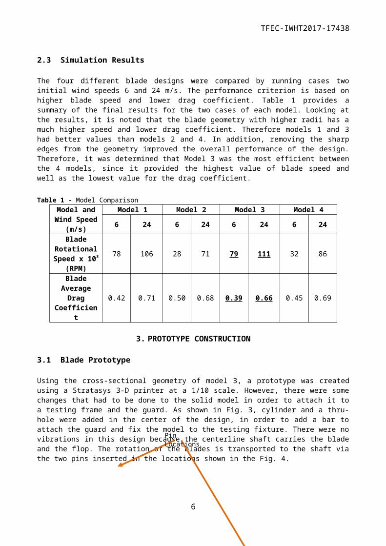
Using the cross-sectional geometry of model 3, a prototype was created using a Stratasys 3-D printer at a 1/10 scale. However, there were some changes that had to be done to the solid model in order to attach it to a testing frame and the guard. As shown in Fig. 3, cylinder and a thru-hole were added in the center of the design, in order to add a bar to attach the guard and fix the model to the testing fixture. There were no vibrations in this design because the centerline shaft carries the blade and the flop. The rotation of the blades is transported to the shaft via the two pins inserted in the locations shown in the Fig. 4.
Fig. 4 Prototype Solid Model 3.2 Guard and Flop
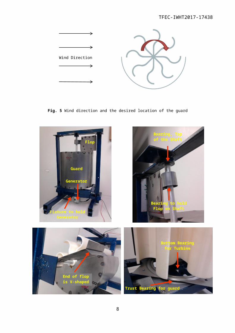
The Guard was made from 24 gauge cold rolled steel sheet. As shown in Fig. 5, the guard covers almost half of the windward face of the turbine in order to prevent negative force on the blades (negative to the direction of blades rotation). The guard and the flop, and the bearing locations are shown in the pictures illustrated by Fig. 6. The size of guard is such that there is a clearance of 8 mm from the tip of the blades. First, the guard was a complete half cylinder covering 180 degrees of the turbine from wind. The test revealed a stagnation effect and thus, the guard was modified to be 175 degrees and this corrected the stagnation without any noticeable effect on the performance. The flop is mounted on the top of the guard and is only to align the guard in correct direction using the wind force. The end of the flop is made as a V-shape in order to eliminate the vibration of the flop. The wind tunnel test shows that the wind aligns the flop with the wind
5
Pin Locations
TFEC-IWHT2017-17438
direction smoothly and holds it there, consequently the guard is located as desired to eliminate the negative force.
Fig. 5 Wind direction and the desired location of the guard
6
Generator
Fixture to hold Generator
Bearing, Top of the Shaft
Bearing to hold Flop on Shaft
End of flop is V-shaped
Flop
Guard
Bottom Bearing for Turbine
Trust Bearing for guard
Wind Direction

TFEC-IWHT2017-17438
Fig. 6 Wind direction and the desired location of the guard
3.3 Frame Structure
The frame structure fixture is made of steel and in the shape of a gate which consisting of two columns on either side of the turbine. The main shaft connected to the generator is supported by the frame structure at the top by an axial bearing and above the generator by a trust bearing. As it was mentioned before, the flop is also held in place with another axial bearing on this shaft, located a bit lower than the top bearing as shown in Fig. 6. The weight of the flop and guard are supported by a large perimeter type trust bearing which was also shown in Fig. 6. The large diameter of this bearing allows to have the trust bearing for the turbine and its housing placed in almost the same height which reduces the total height of the turbine.
4. PROTOTYPE EVALUATION
4.1 Theoretical Evaluation
Evaluation of any wind turbine is based on how it transforms the power of the wind into mechanical power. The available power (Pa) from wind can be calculated by the following relationship [7].
Pa=12
ρ Ap V 3 (1)
where ρ is the air density (1.22 kg/m3), Ap is the projected area (0.02 m2) , and V is the wind velocity.
The transformed power (Pw) is evaluated by using the electricity produced by the rotation of the turbine. The generated power is given by:
Pw=V × I (2)
where V is the voltage difference (V) and I is the current (A).
In addition, the power coefficient (Cp) is calculated using Pa and Pw using the following relationship:
C p=Pw
Pa(3)
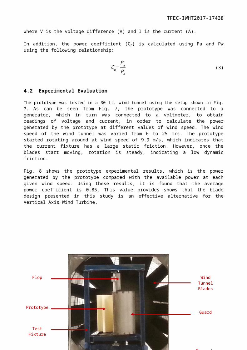
4.2 Experimental Evaluation
The prototype was tested in a 30 ft. wind tunnel using the setup shown in Fig. 7. As can be seen from Fig. 7, the prototype was connected to a generator, which in turn was connected to a voltmeter, to obtain readings of voltage and current, in order to calculate the power generated by the prototype at different values of wind speed. The wind speed of the wind tunnel was varied from 6 to 25 m/s. The prototype started rotating around at wind speed of 9.9 m/s, which indicates that the current fixture has a large static friction. However, once the blades start moving, rotation is steady, indicating a low dynamic friction.
Fig. 8 shows the prototype experimental results, which is the power generated by the prototype compared with the available power at each given wind speed. Using these results, it is found that the average power
7
TFEC-IWHT2017-17438
coefficient is 0.85. This value provides shows that the blade design presented in this study is an effective alternative for the Vertical Axis Wind Turbine.
Fig. 7 - Turbine Testing Setup in Wind Tunnel
8
Generator
Flop Wind Tunnel Blades
GuardPrototype
Test Fixture

TFEC-IWHT2017-17438
9 11 13 15 17 19 21 23 250
50
100
150
200
Mechanical PowerAvailable Power
Wind Speed (m/s)
Pow
er (W
)
Fig. 8 - Prototype Experimental Result5. CONCLUSIONS
In this research a novel vertical axis wind turbine is presented. The performance of the selected blade shape was tested and compared to three other assumed shapes using Computational Flow Dynamics. Next, a prototype of the turbine was manufactured with the selected configuration for the blades. The performance of the turbine was then tested in a wind tunnel for speeds between 6 to 25 meters per second. The power curve was created by reading the voltage and amperage of the attached power generator. This power curve was compared to the theoretical power calculated from the equation (1) presented in this paper. The performance of this turbine is promising and has a very satisfactory efficiency which shows the suitability of this turbine for small application. In addition to the high efficiency, this turbine has no flickering effect so it is easy on eyes. Furthermore it runs very quietly. The other important feature is that when rotating, it looks like a wall and birds will see it and can avoid flying into it; this is contrary to HAWT, in which the blades seem non-existing in fast angular velocity (or rpm). Another important turbine performance parameter, which is a positive feature of all VAWT juxtaposed to HAWT, is the wake effect. The working envelope of this turbine is very compact and the wake effect is not very large. The outcome of this study proves that the new design is an effective alternative for the Vertical Axis Wind Turbine, and it should be investigated further and compared to other VAWT and HAWT.
ACKNOWLEDGMENT
This work was supported by a CSU - AAUP Research Grant.
REFERENCES
9
TFEC-IWHT2017-17438
[1] http://www.ren21.net/status-of-renewables/global-status-report/
[2] http://www.homedepot.com
[3] Cooper, P. & Kennedy, O. C. (2004). “Development and Analysis of a Novel Vertical Axis Wind Turbine”, Proceedings Solar 2004 - Life, The Universe and Renewables (pp. 1-9). Perth, Australia: Australian and New Zealand Solar Energy Society (ANZSES).
[4] Peace, S. (2004), Another Approach to Wind, Mechanical Engineering, ASME, June 2004, 28-31.
[5] M. El-Samanoudy, A.A.E. Ghorab, Sh.Z. Youssef, (2010), “Effect of some design parameters on the performance of a Giromill vertical axis wind turbine”, Ain Shams Engineering Journal, 1, pp 85–95.
[6] K. Pope, V. Rodrigues, R. Doyle, A. Tsopelas, R. Gravelsins, G.F. Naterer, E. Tsang, (2010), “Effects of stator vanes on power coefficients of a zephyr vertical axis wind turbine”, Renewable Energy, 35, pp 1043–1051.
[7] B. N. Patil , Vani V, Rahul B. Badde, Rajshekhar Kuragund, and Honnappa Y. Hanjagi, (2014), “Axial Flux Vertical Axis Wind Turbine”, International Journal of Research in Engineering Technology and Management, 2(3), pp. 1-6.
[8] Terrence C. Sankar and Robert Morris, “The Case for Vertical Axis Wind Turbines”, Clean Technology 2008, www.ct-si.org, ISBN 978-1-4200-8502-0, pp 136-139.
10