sallis installation & maintenance guide · sallis installation & maintenance guide issue:...
TRANSCRIPT

SALLIS Installation &
Maintenance Guide
Issue: 01.10
2012/07/03
Author: Jon Mendizabal
Salto Systems S.L. 2012
SALLIS Installation & Maintenance Guide
Issue: 01.10
Confidential © Salto Systems S.L. 2012 2/41
Version information
Issue Date Author Description
01.00 2010/11/02 J.Mendizabal First version.
01.01 2010/11/08 J.Mendizabal Included Firmware Update procedure.
01.02 2010/11/19 J.Mendizabal - Included Router Update procedure.
- Included PPD Firmware Update procedure. - System maintenance revised.
01.03 2010/12/10 J.Mendizabal
- Clarification: References to ‘Database’ changed to ‘Router File’.
- ‘Systems Components’ figure modified. - Included references to RS485 Termination Resistor.
01.04 2011/02/10 J.Mendizabal - Include chapter with Device Minimum Firmware versions for
correct operation.
01.05 2011/03/16 J.Mendizabal
I.Garmendia
- Included new pre-installation mode for Sallis locks.
- Hardware Setup section extended. - Updated table of Valid Firmware Versions.
01.06 2011/07/12 J.Mendizabal - Included Desfire and MifarePlus card types
01.07 2011/10/12 X.Ramirez - Router PoE added
01.08 2012/04/13 M. García - Included validity of data on PPD.
01.09 2012/06/27 J.Gutierrez - Included router limits and installation examples.
01.10 2012/07/03 X.Ramirez - New Router PoE web server page (6.2)
- Changes in offline behaviour (4.2.3)

SALLIS Installation & Maintenance Guide
Issue: 01.10
Confidential © Salto Systems S.L. 2012 3/41
Table of Contents
1 SYSTEM SETUP ............................................................................................................................. 6
1.1 System Definition ................................................................................................................... 6 1.2 System Components ............................................................................................................... 6 1.3 Setup Process ........................................................................................................................ 7
2 HARDWARE SETUP WITH ROUTER RS485 ........................................................................................ 8
2.1 Overview ............................................................................................................................... 8 2.1.1 Power supply ........................................................................................................................ 9 2.1.2 Limits and Recommendations ................................................................................................. 9
2.2 Host to Router connection ...................................................................................................... 11 2.2.1 Wiring ................................................................................................................................ 11 2.2.2 Termination Resistor ............................................................................................................ 11
2.3 Router to Nodes connection .................................................................................................... 11 2.3.1 Wiring ................................................................................................................................ 11 2.3.2 Termination Resistor ............................................................................................................ 11
3 HARDWARE SETUP WITH A ROUTER POE ........................................................................................ 12
3.1 Overview .............................................................................................................................. 12 3.1.1 Power supply ....................................................................................................................... 13 3.1.2 Limits and Recommendations ................................................................................................ 13
3.2 Host to Router connection ...................................................................................................... 15 3.2.1 Wiring ................................................................................................................................ 15
3.3 Router to Nodes connection .................................................................................................... 15 3.3.1 Wiring ................................................................................................................................ 15 3.3.2 Termination Resistor ............................................................................................................ 15
4 ROUTER CONFIGURATION SETUP ................................................................................................... 16
4.1 Overview .............................................................................................................................. 16 4.2 Data base Setup process ........................................................................................................ 16
4.2.1 Add New Card type .............................................................................................................. 18 4.2.2 Add new Nodes .................................................................................................................... 19 4.2.3 Add new Doors .................................................................................................................... 21
5 DEVICES SETUP ........................................................................................................................... 22
5.1 Overview .............................................................................................................................. 22 5.2 Download data to PPD. ........................................................................................................... 22 5.3 Update Routers ..................................................................................................................... 23 5.4 Initialize Locks ...................................................................................................................... 23 5.5 Router LEDS ......................................................................................................................... 25
5.5.1 Router 485 .......................................................................................................................... 25 5.5.2 Router PoE .......................................................................................................................... 25
5.6 Node LED ............................................................................................................................. 26 5.7 Lock LED .............................................................................................................................. 26
6 ROUTER POE – HOST COMMUNICATION SETUP ................................................................................ 27
6.1 Starting the Router ................................................................................................................ 27 6.2 Configuration Parameters ....................................................................................................... 27 6.3 Create a Socket .................................................................................................................... 30
7 LOCK IN PRE-INSTALLATION MODE ................................................................................................ 32
7.1 Introduction.......................................................................................................................... 32 7.2 How to proceed ..................................................................................................................... 32 7.3 Lock behaviour ..................................................................................................................... 32
8 SYSTEM MAINTENANCE ................................................................................................................. 33
8.1 System Diagnosis .................................................................................................................. 33 8.2 Router replacement. .............................................................................................................. 34 8.3 Node replacement. ................................................................................................................ 34 8.4 Lock replacement. ................................................................................................................. 35
9 LOCK FIRMWARE UPDATE ............................................................................................................. 36
9.1 Introduction.......................................................................................................................... 36 9.2 Firmware Diagnostic .............................................................................................................. 36 9.3 Firmware Update ................................................................................................................... 37
10 PPD FIRMWARE UPDATE ............................................................................................................ 39
SALLIS Installation & Maintenance Guide
Issue: 01.10
Confidential © Salto Systems S.L. 2012 4/41
10.1 Current version ..................................................................................................................... 39 10.2 Firmware Update ................................................................................................................... 39
11 VALID FIRMWARE VERSIONS ..................................................................................................... 41
11.1 With RS485 Router ................................................................................................................ 41 11.2 With Router PoE .................................................................................................................... 41
Table Index
Table 1-1 System Components ............................................................................... 6
Table 2-1 Number of nodes supported & distance Limits ............................................ 9
Table 4-1 Installation Data Parameters .................................................................. 17
Table 4-2 Mifare Classic Card type Parameters ........................................................ 18
Table 4-3 Mifare Plus Card type Parameters............................................................ 19
Table 4-4 Desfire and Desfire EV1 Card type Parameters .......................................... 19
Table 4-5 Node Parameters .................................................................................. 20
Table 4-6 Lock Parameters ................................................................................... 21
Table 5-1 Router RS485 LEDS .............................................................................. 25
Table 5-2 Router PoE LEDS................................................................................... 25
Table 8-1 Diagnosis info screen data. .................................................................... 34
Table 9-1 Electronic modules within a lock and Device Numbers ............................... 36
Table 11-1 Electronic Devices vs. Minimum Firmware Versions .................................. 41
Figure Index
Figure 1-1 System Components .............................................................................. 6
Figure 2-1 Hardware setup diagram ......................................................................... 8
Figure 2-2 Router 485 limits ................................................................................... 8
Figure 2-3 Installation example 1 Router RS485...................................................... 10
Figure 2-4 Installation example 2 Router RS485...................................................... 10
Figure 2-5 Installation example 3 Router RS485...................................................... 10
Figure 2-6 Installation example 4 Router RS485...................................................... 10
Figure 2-7 Host To Router 4-wire connection .......................................................... 11
Figure 2-8 Router to Nodes 4-wire connectors ........................................................ 11
Figure 2-9 Intermediate Node: Jumper between ‘R’ and ‘OFF’ pins ........................... 11
Figure 2-10 End Node: Jumper between ‘R’ and ‘ON’ pins ......................................... 11
Figure 3-1 Hardware Setup Diagram ...................................................................... 12
Figure 3-2 Router PoE Limits ................................................................................ 12
Figure 3-3 Router PoE Power Supply ...................................................................... 13
Figure 3-4 Internal Node ...................................................................................... 13
Figure 3-5 Installation example 1 Router PoE.......................................................... 14
Figure 3-6 Installation example 2 Router PoE.......................................................... 14
SALLIS Installation & Maintenance Guide
Issue: 01.10
Confidential © Salto Systems S.L. 2012 5/41
Figure 3-7 Installation example 3 Router PoE.......................................................... 14
Figure 3-8 Installation example 4 Router PoE.......................................................... 14
Figure 3-9 Router to Nodes 4-wire connectors ........................................................ 15
Figure 3-10 Intermediate Node: Jumper between ‘R’ and ‘OFF’ pins ......................... 15
Figure 3-11 End Node: Jumper between ‘R’ and ‘ON’ pins ......................................... 15
Figure 4-1 Create new Router file: select new database ........................................... 16
Figure 4-2 Create new Router File: choose location and file name. ............................ 16
Figure 4-3 Create New Router File: create password ................................................ 16
Figure 4-4 Installation Data Parameters ................................................................. 17
Figure 4-5 Create New Card type .......................................................................... 18
Figure 4-6 Create New Card type Parameters ......................................................... 18
Figure 4-7 Node Parameters ................................................................................. 20
Figure 4-8 Create new Door Parameters ................................................................. 21
Figure 5-1 PPD icon ............................................................................................. 22
Figure 6-1 Sallis Router Web Page ......................................................................... 28
Figure 6-2 Port Configuration ................................................................................ 28
Figure 6-3 DHCP Configuration.............................................................................. 28
Figure 6-4 IP Static Configuration .......................................................................... 29
Figure 6-5 Router Name ....................................................................................... 29
Figure 6-6 Feedback message ............................................................................... 30
Figure 8-1 Node Replacement: step 1. ................................................................... 34
Figure 8-2 Node Replacement: step 2 .................................................................... 35
Figure 9-1 Firmware Updates: Download files to PPD. .............................................. 37
Figure 9-2 Firmware Updates: Select and add files to Download ................................ 37
Figure 9-3 Send files to PPD ................................................................................. 38
Figure 9-4 Send files to PPD: warning message ....................................................... 38
Figure 10-1 Update PPD firmware .......................................................................... 39
Figure 10-2 Open Update PPD firmware file ............................................................ 40

SALLIS Installation & Maintenance Guide
Issue: 01.10
Confidential © Salto Systems S.L. 2012 6/41
1 SYSTEM SETUP
1.1 System Definition
SALLIS (SAlto Lock LInk System) is a solution to connect the SALTO Wireless locks to a
third party Access Control System named Host.
1.2 System Components
The following figure shows a schematic overview of the system components:
Figure 1-1 System Components
HOST – Control Panel Third party Access Control Software.
ROUTER Salto Wireless communications central manager device.
NODE Salto RS485 to wireless bridge.
Salto Locks
Any wireless lock device manufactured or sold by Salto to control the physical access to a premise: the XS4 electronic locks, Aelement
series, GEO electronic cylinder and any other compatible locks developed by Salto in the future.
PPD Portable Programmer Device for Router and Locks initialization. It is also a diagnosis tool and a way to open the lock in case of battery failure.
SALLIS App The SALLIS Application is the piece of software that handles all the information regarding the SALLIS system. The information for each
installation is stored in a specific Database.
Router Config.File
Encrypted file including setup parameters of the Router and related nodes and doors.
Table 1-1 System Components
HOST – Control Panel
SALLIS
SetUp App
RS485 BUS OR ETHERNET RJ45
USB
Router
Config. File
Salto Nodes
Salto Locks
Salto Router
RS485 BUS „2‟

SALLIS Installation & Maintenance Guide
Issue: 01.10
Confidential © Salto Systems S.L. 2012 7/41
1.3 Setup Process
The Setup process includes 3 steps:
Hardware Setup: Hardwire the communication devices HOST-ROUTERS-NODES.
Router Configuration Setup: Define the system in SALLIS Application:
- Create a Router configuration file.
- Create the list of allowed card types.
- Create the list of Nodes with their MAC wireless address.
- Create the list of Locks including the nodes each of them belong to.
Devices Setup:
- Download the information to a PPD.
- Initialize the Router and the Locks with the PPD.
SALLIS Installation & Maintenance Guide
Issue: 01.10
Confidential © Salto Systems S.L. 2012 8/41
2 HARDWARE SETUP WITH ROUTER RS485
The Host communicates with the Router through an RS485 Link or Ethernet depending
on the router device. This chapter specifies the hardware setup with a RS485 Router.
2.1 Overview
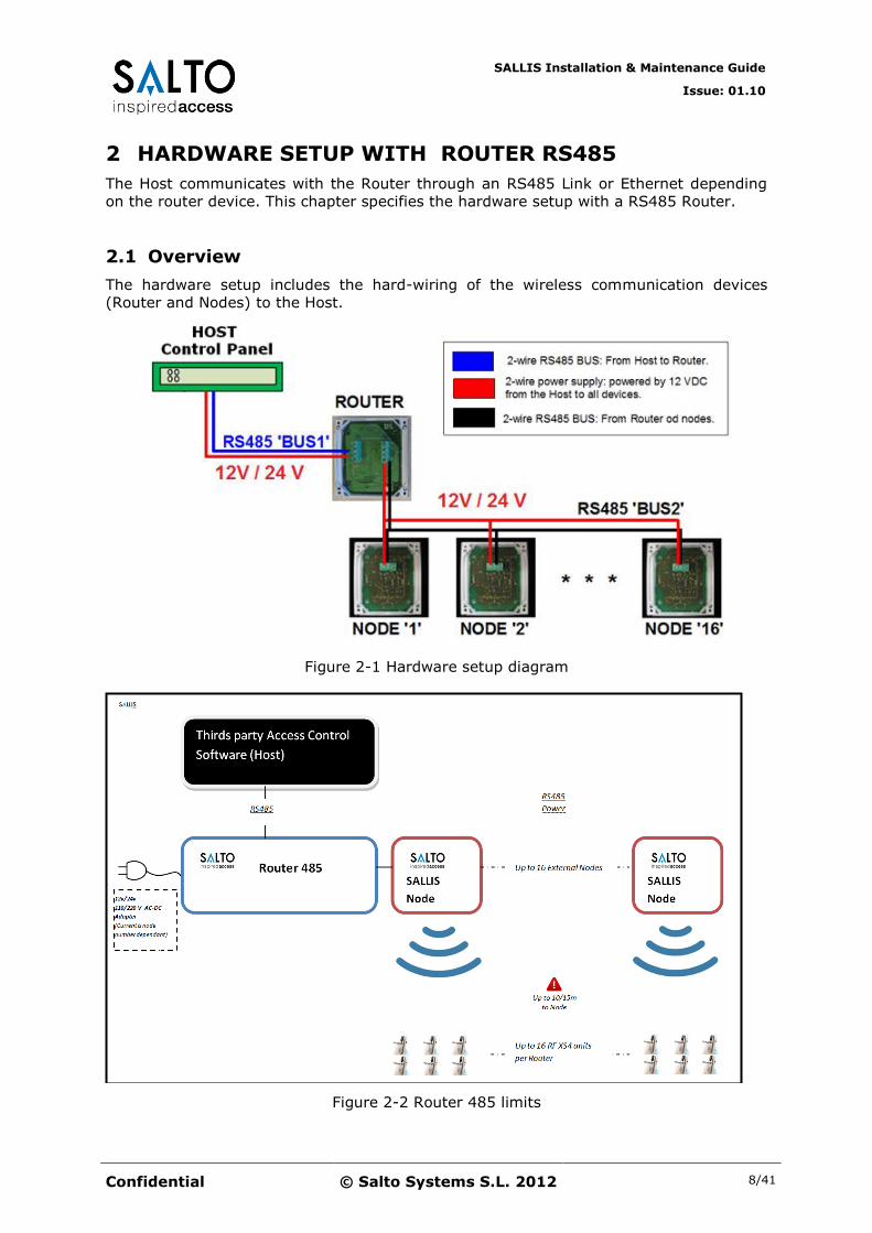
The hardware setup includes the hard-wiring of the wireless communication devices
(Router and Nodes) to the Host.
Figure 2-1 Hardware setup diagram
Figure 2-2 Router 485 limits
SALLIS Installation & Maintenance Guide
Issue: 01.10
Confidential © Salto Systems S.L. 2012 9/41
2.1.1 Power supply
The Router and the Nodes are powered by 12/24 VDC from the Host.
The Router has a current consumption of 75mA and the current consumption of each node is 45mA.
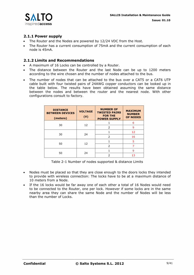
2.1.2 Limits and Recommendations
A maximum of 16 Locks can be controlled by a Router.
The distance between the Router and the last Node can be up to 1200 meters
according to the wire chosen and the number of nodes attached to the bus.
The number of nodes that can be attached to the bus over a CAT5 or a CAT6 UTP
cable built with four twisted pairs of 24AWG copper conductors can be looked up in
the table below. The results have been obtained assuming the same distance
between the nodes and between the router and the nearest node. With other
configurations consult to factory.
DISTANCE BETWEEN DEVICES
(meters)
VOLTAGE
(V)
NUMBER OF TWISTED PAIRS
FOR THE POWER SUPPLY
MAXIMUM NUMBER
OF NODES
30 12 1 6
2 9
30 24 1 12
2 16
50 12 1 5
2 7
50 24 1 9
2 13
Table 2-1 Number of nodes supported & distance Limits
Nodes must be placed so that they are close enough to the doors locks they intended
to provide with wireless connection: The locks have to be at a maximum distance of 10 meters from a Node.
If the 16 locks would be far away one of each other a total of 16 Nodes would need
to be connected to the Router, one per lock. However if some locks are in the same
nearby area they can share the same Node and the number of Nodes will be less than the number of Locks.
SALLIS Installation & Maintenance Guide
Issue: 01.10
Confidential © Salto Systems S.L. 2012 10/41
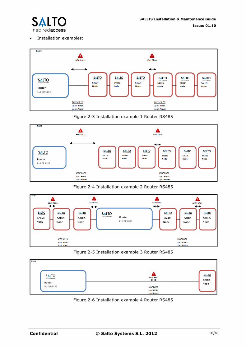
Installation examples:
Figure 2-3 Installation example 1 Router RS485
Figure 2-4 Installation example 2 Router RS485
Figure 2-5 Installation example 3 Router RS485
Figure 2-6 Installation example 4 Router RS485
SALLIS Installation & Maintenance Guide
Issue: 01.10
Confidential © Salto Systems S.L. 2012 11/41
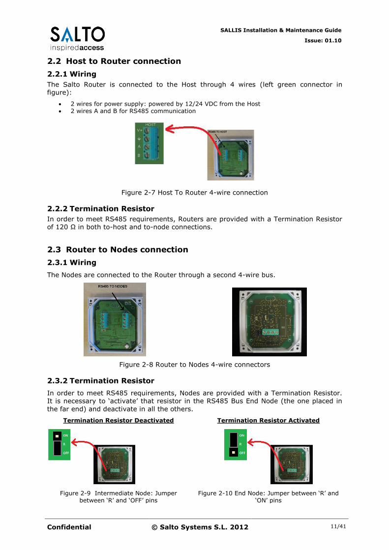
2.2 Host to Router connection
2.2.1 Wiring
The Salto Router is connected to the Host through 4 wires (left green connector in
figure):
2 wires for power supply: powered by 12/24 VDC from the Host 2 wires A and B for RS485 communication
Figure 2-7 Host To Router 4-wire connection
2.2.2 Termination Resistor
In order to meet RS485 requirements, Routers are provided with a Termination Resistor
of 120 Ω in both to-host and to-node connections.
2.3 Router to Nodes connection
2.3.1 Wiring
The Nodes are connected to the Router through a second 4-wire bus.
Figure 2-8 Router to Nodes 4-wire connectors
2.3.2 Termination Resistor
In order to meet RS485 requirements, Nodes are provided with a Termination Resistor.
It is necessary to ‘activate’ that resistor in the RS485 Bus End Node (the one placed in
the far end) and deactivate in all the others.
Termination Resistor Deactivated
Figure 2-9 Intermediate Node: Jumper between ‘R’ and ‘OFF’ pins
Termination Resistor Activated
Figure 2-10 End Node: Jumper between ‘R’ and ‘ON’ pins

SALLIS Installation & Maintenance Guide
Issue: 01.10
Confidential © Salto Systems S.L. 2012 12/41
3 HARDWARE SETUP WITH A ROUTER POE
This chapter specifies the hardware setup needed for Sallis System with a Router PoE.
3.1 Overview
Figure 3-1 Hardware Setup Diagram
Figure 3-2 Router PoE Limits

SALLIS Installation & Maintenance Guide
Issue: 01.10
Confidential © Salto Systems S.L. 2012 13/41
3.1.1 Power supply
The Router and Nodes can be powered through PoE supporting the IEEE802.3at
standard as a type1 6W class 2 PD. Alternatively a plug power supply of 500mA at 12
volts can be used if ‘PoE’ is not supported in the installation.
Figure 3-3 Router PoE Power Supply
3.1.2 Limits and Recommendations
A maximum of 7 Nodes can be controlled by a Router PoE: 6 Nodes connected to the
RS485 bus plus one internal node. Each node can control a maximum of 16 Locks.
Figure 3-4 Internal Node
The maximum number of Locks controlled by a Router PoE is 64 Locks.
The distance between the Router and the last Node can be up to 1200 meters
according to the wire chosen and the number of nodes attached to the bus.
Nodes must be placed so that they are close enough to the doors locks they intended
to provide with wireless connection: The locks have to be at a maximum distance of 10 meters from a Node.
If the 64 locks would be far away one of each other a total of 7 Nodes would need to
be connected to the Router. However if some locks are in the same nearby area they
can share the same Node and the number of Nodes will be less than the number of Locks.
SALLIS Installation & Maintenance Guide
Issue: 01.10
Confidential © Salto Systems S.L. 2012 14/41
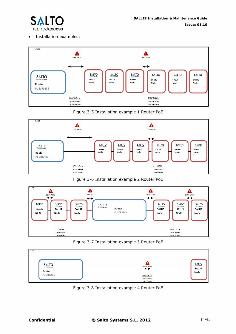
Installation examples:
Figure 3-5 Installation example 1 Router PoE
Figure 3-6 Installation example 2 Router PoE
Figure 3-7 Installation example 3 Router PoE
Figure 3-8 Installation example 4 Router PoE
SALLIS Installation & Maintenance Guide
Issue: 01.10
Confidential © Salto Systems S.L. 2012 15/41
3.2 Host to Router connection
3.2.1 Wiring
The Salto Router can be connected to the Host through a RJ45 wire in a 10Base-T or
100Base-Tx Ethernet Lan.
3.3 Router to Nodes connection
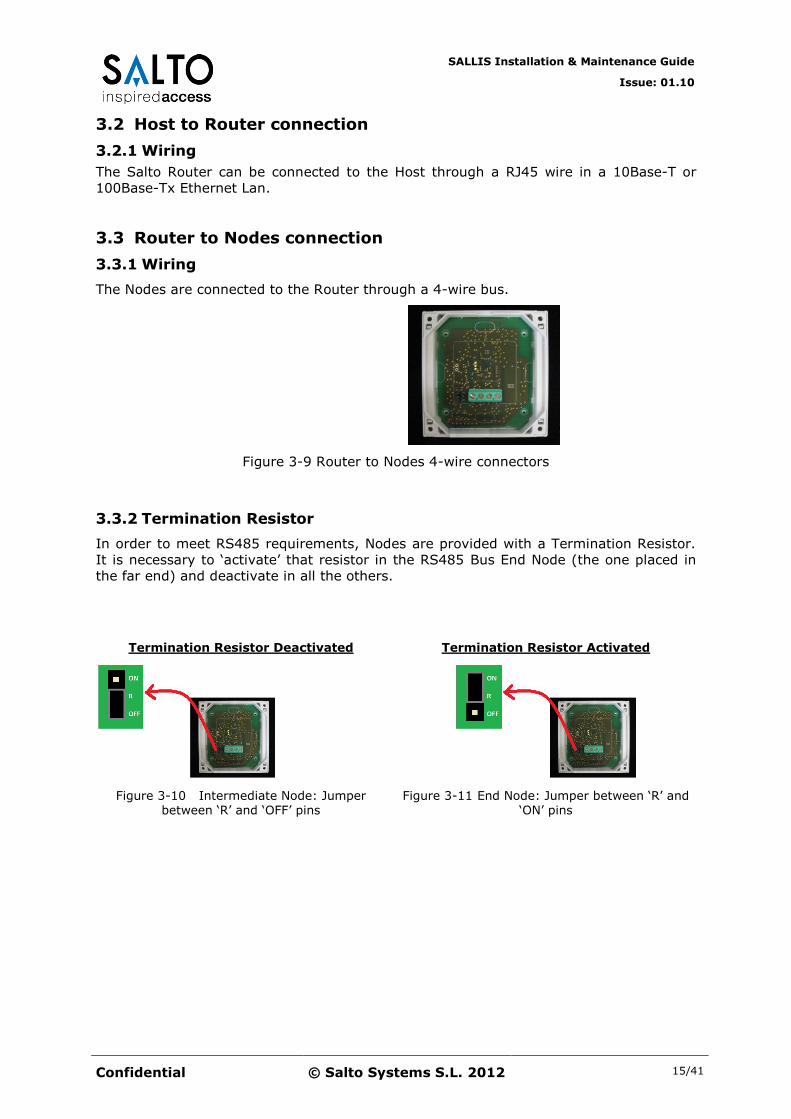
3.3.1 Wiring
The Nodes are connected to the Router through a 4-wire bus.
Figure 3-9 Router to Nodes 4-wire connectors
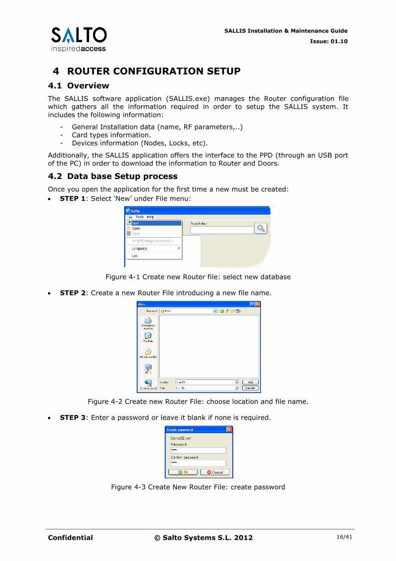
3.3.2 Termination Resistor
In order to meet RS485 requirements, Nodes are provided with a Termination Resistor.
It is necessary to ‘activate’ that resistor in the RS485 Bus End Node (the one placed in
the far end) and deactivate in all the others.
Termination Resistor Deactivated
Figure 3-10 Intermediate Node: Jumper between ‘R’ and ‘OFF’ pins
Termination Resistor Activated
Figure 3-11 End Node: Jumper between ‘R’ and ‘ON’ pins
SALLIS Installation & Maintenance Guide
Issue: 01.10
Confidential © Salto Systems S.L. 2012 16/41
4 ROUTER CONFIGURATION SETUP
4.1 Overview
The SALLIS software application (SALLIS.exe) manages the Router configuration file
which gathers all the information required in order to setup the SALLIS system. It
includes the following information:
- General Installation data (name, RF parameters,..)
- Card types information.
- Devices information (Nodes, Locks, etc).
Additionally, the SALLIS application offers the interface to the PPD (through an USB port
of the PC) in order to download the information to Router and Doors.
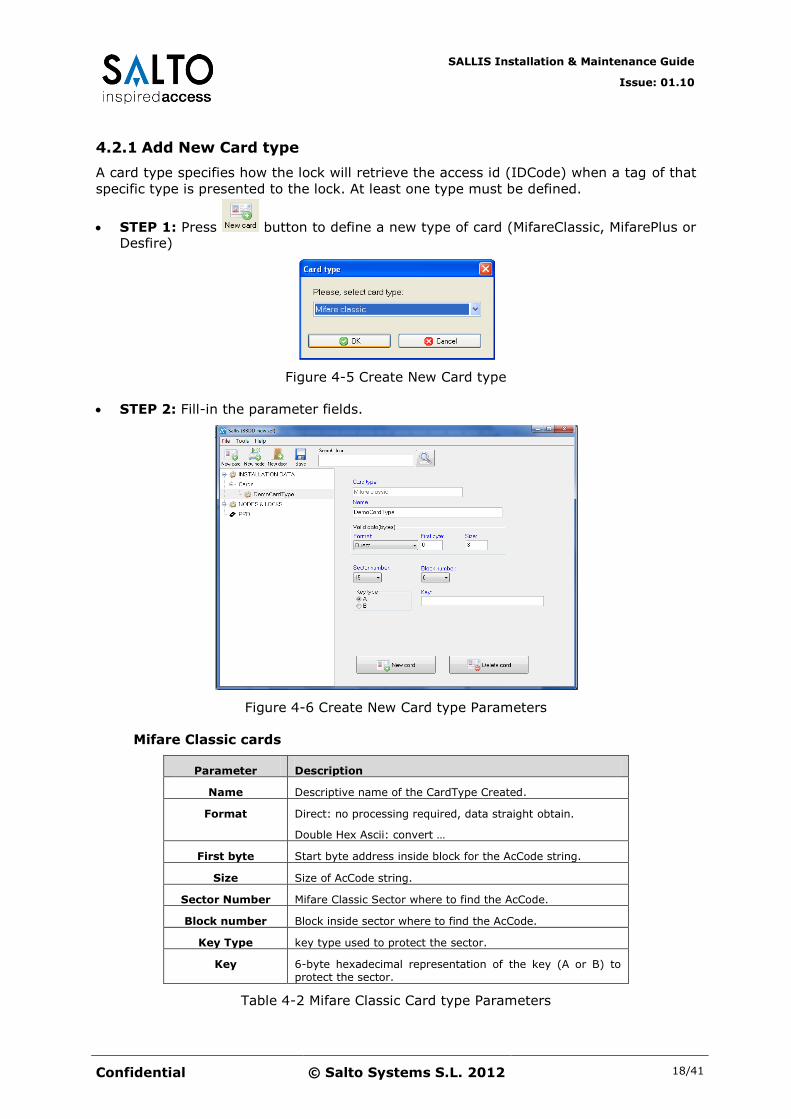
4.2 Data base Setup process
Once you open the application for the first time a new must be created:
STEP 1: Select ‘New’ under File menu:
Figure 4-1 Create new Router file: select new database
STEP 2: Create a new Router File introducing a new file name.
Figure 4-2 Create new Router File: choose location and file name.
STEP 3: Enter a password or leave it blank if none is required.
Figure 4-3 Create New Router File: create password

SALLIS Installation & Maintenance Guide
Issue: 01.10
Confidential © Salto Systems S.L. 2012 17/41
After the Router File is created, general parameter fields must be filled.
STEP 4: Select ‘INSTALLATION DATA’ icon in the explore-like window:
Figure 4-4 Installation Data Parameters
STEP 5: fill-in the following fields in the Installation descriptor:
Router Model Select the Router Device type
Name Descriptive name of the Installation
IDCodeSize UID: portion of tag’s UID to use when retriving an IDCode.
AcCode: portion of length of data stored in tag memory
IDCODE = UID(UIDLength) + ACCODE(AcCode)
Enable door Beep Check if locks should activate acoustic signalling when operated (Open, close, etc..).
Site RF Channels List of 2.4GHz band channels allowed to be used in wireless network.
Table 4-1 Installation Data Parameters
SALLIS Installation & Maintenance Guide
Issue: 01.10
Confidential © Salto Systems S.L. 2012 18/41
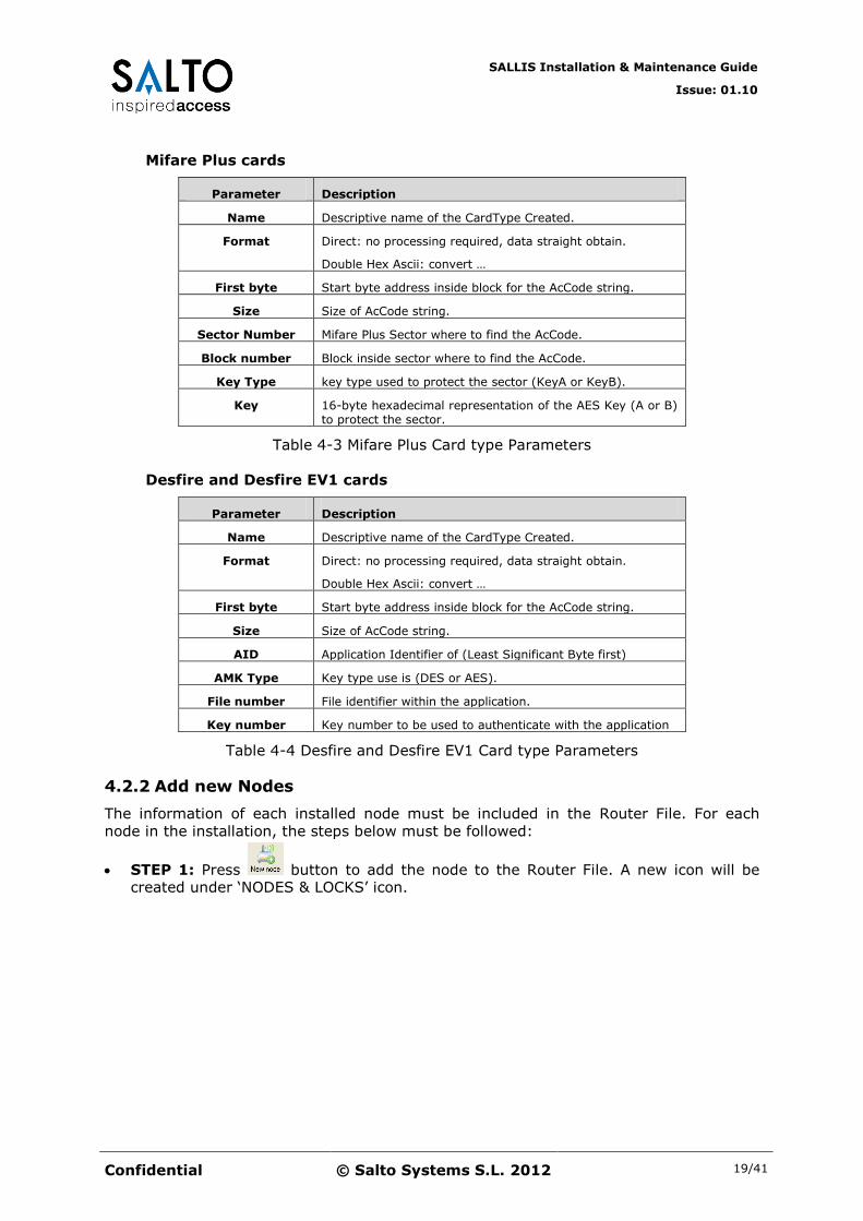
4.2.1 Add New Card type
A card type specifies how the lock will retrieve the access id (IDCode) when a tag of that
specific type is presented to the lock. At least one type must be defined.
STEP 1: Press button to define a new type of card (MifareClassic, MifarePlus or Desfire)
Figure 4-5 Create New Card type
STEP 2: Fill-in the parameter fields.
Figure 4-6 Create New Card type Parameters
Mifare Classic cards
Parameter Description
Name Descriptive name of the CardType Created.
Format Direct: no processing required, data straight obtain.
Double Hex Ascii: convert …
First byte Start byte address inside block for the AcCode string.
Size Size of AcCode string.
Sector Number Mifare Classic Sector where to find the AcCode.
Block number Block inside sector where to find the AcCode.
Key Type key type used to protect the sector.
Key 6-byte hexadecimal representation of the key (A or B) to protect the sector.
Table 4-2 Mifare Classic Card type Parameters
SALLIS Installation & Maintenance Guide
Issue: 01.10
Confidential © Salto Systems S.L. 2012 19/41
Mifare Plus cards
Parameter Description
Name Descriptive name of the CardType Created.
Format Direct: no processing required, data straight obtain.
Double Hex Ascii: convert …
First byte Start byte address inside block for the AcCode string.
Size Size of AcCode string.
Sector Number Mifare Plus Sector where to find the AcCode.
Block number Block inside sector where to find the AcCode.
Key Type key type used to protect the sector (KeyA or KeyB).
Key 16-byte hexadecimal representation of the AES Key (A or B) to protect the sector.
Table 4-3 Mifare Plus Card type Parameters
Desfire and Desfire EV1 cards
Parameter Description
Name Descriptive name of the CardType Created.
Format Direct: no processing required, data straight obtain.
Double Hex Ascii: convert …
First byte Start byte address inside block for the AcCode string.
Size Size of AcCode string.
AID Application Identifier of (Least Significant Byte first)
AMK Type Key type use is (DES or AES).
File number File identifier within the application.
Key number Key number to be used to authenticate with the application
Table 4-4 Desfire and Desfire EV1 Card type Parameters
4.2.2 Add new Nodes
The information of each installed node must be included in the Router File. For each
node in the installation, the steps below must be followed:
STEP 1: Press button to add the node to the Router File. A new icon will be created under ‘NODES & LOCKS’ icon.

SALLIS Installation & Maintenance Guide
Issue: 01.10
Confidential © Salto Systems S.L. 2012 20/41
Figure 4-7 Node Parameters
STEP 2: fill the following fields in the Node descriptor:
Parameter Description
ID Node This parameter will be automatically assigned (from ‘N1’ up to ‘N16’) by the application.
Description Description of the Node created.
MAC address MAC address included in the sticker at the back of the device.
Table 4-5 Node Parameters
STEP 3: Press button to save the recently created Node to the Router File.
SALLIS Installation & Maintenance Guide
Issue: 01.10
Confidential © Salto Systems S.L. 2012 21/41
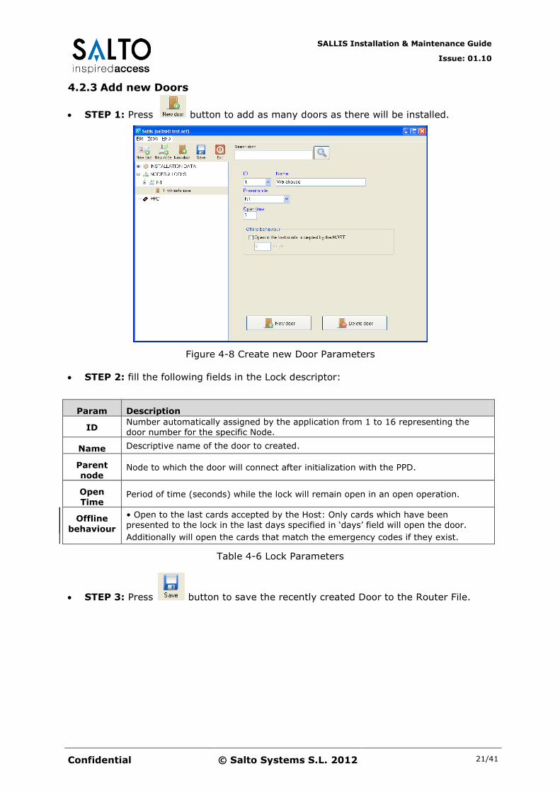
4.2.3 Add new Doors
STEP 1: Press button to add as many doors as there will be installed.
Figure 4-8 Create new Door Parameters
STEP 2: fill the following fields in the Lock descriptor:
Param Description
ID Number automatically assigned by the application from 1 to 16 representing the door number for the specific Node.
Name Descriptive name of the door to created.
Parent node
Node to which the door will connect after initialization with the PPD.
Open Time
Period of time (seconds) while the lock will remain open in an open operation.
Offline
behaviour
• Open to the last cards accepted by the Host: Only cards which have been presented to the lock in the last days specified in ‘days’ field will open the door.
Additionally will open the cards that match the emergency codes if they exist.
Table 4-6 Lock Parameters
STEP 3: Press button to save the recently created Door to the Router File.
SALLIS Installation & Maintenance Guide
Issue: 01.10
Confidential © Salto Systems S.L. 2012 22/41
5 DEVICES SETUP
5.1 Overview
The device setup consists of downloading the data defined in the Router File to the
Router and each of the locks.
Note: Nodes are automatically configured by the Router. No
further actions are required.
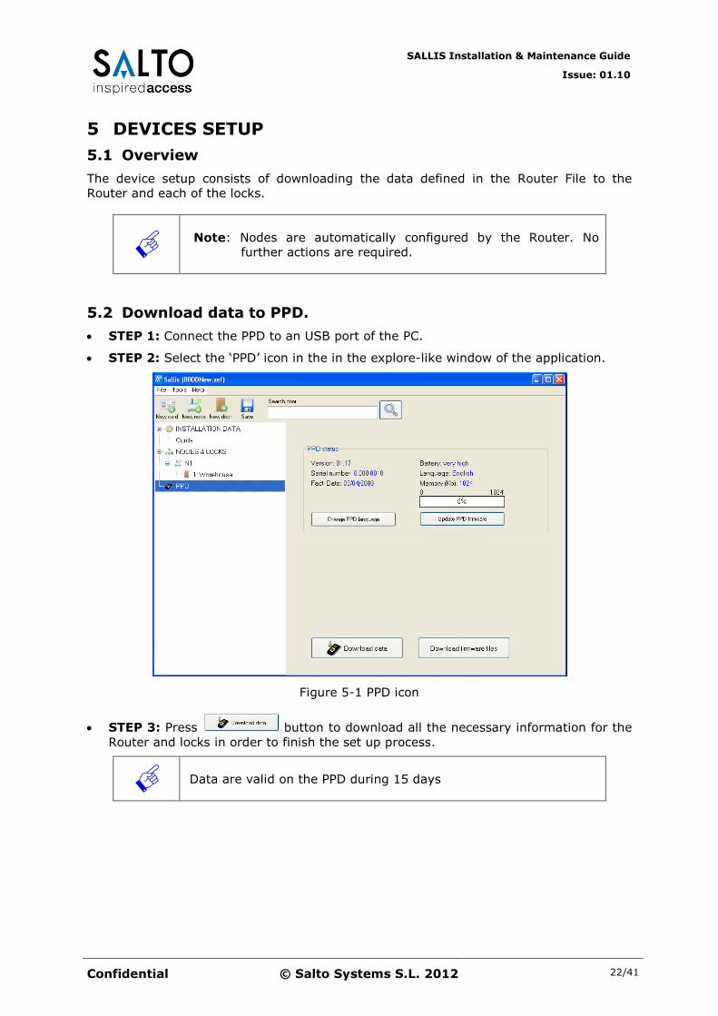
5.2 Download data to PPD.
STEP 1: Connect the PPD to an USB port of the PC.
STEP 2: Select the ‘PPD’ icon in the in the explore-like window of the application.
Figure 5-1 PPD icon
STEP 3: Press button to download all the necessary information for the
Router and locks in order to finish the set up process.
Data are valid on the PPD during 15 days

SALLIS Installation & Maintenance Guide
Issue: 01.10
Confidential © Salto Systems S.L. 2012 23/41
5.3 Update Routers
STEP 1: Switch on the PPD and select the ‘Update Router’ option in the general
menu.
STEP 2: Connect the PPD connector to the Router to be initialized and press ‘OK’.
STEP 3: Error case: if the PPD shows ‘ERROR DOESN’T BELONG TO THE SYSTEM’
proceed again with step 2 keeping the clear button of the router pressed.
STEP 4: Initialization finishes when ‘UPDATED’ message is displayed.
5.4 Initialize Locks
STEP 1: Switch on the PPD and select the ‘INITIALIZE LOCK’ option (use arrow
buttons to navigate) in the general menu.

SALLIS Installation & Maintenance Guide
Issue: 01.10
Confidential © Salto Systems S.L. 2012 24/41
STEP 2: After pressing ‘OK’ a list of all doors is displayed (use arrow buttons to
navigate) Select the correct lock in the lock list in the screen and press OK.
STEP 3: Connect PPD cable in the PPD connection socket of the lock.
Error case: if the PPD shows ‘ERROR DOESN’T BELONG TO THE SYSTEM’ proceed
again with STEP 2 keeping the clear button of the lock pressed.
STEP 4: When the PPD finalizes the initialization process the lock tries to connect
with the assigned Node. It will show the result of the operation with:
Green LED flash: the lock is successfully connected to the Node.
Red LED flash: the lock indicates a connection error. Check that the node is
correctly installed, initialized, within range and proceed with STEP 1 again.
SALLIS Installation & Maintenance Guide
Issue: 01.10
Confidential © Salto Systems S.L. 2012 25/41
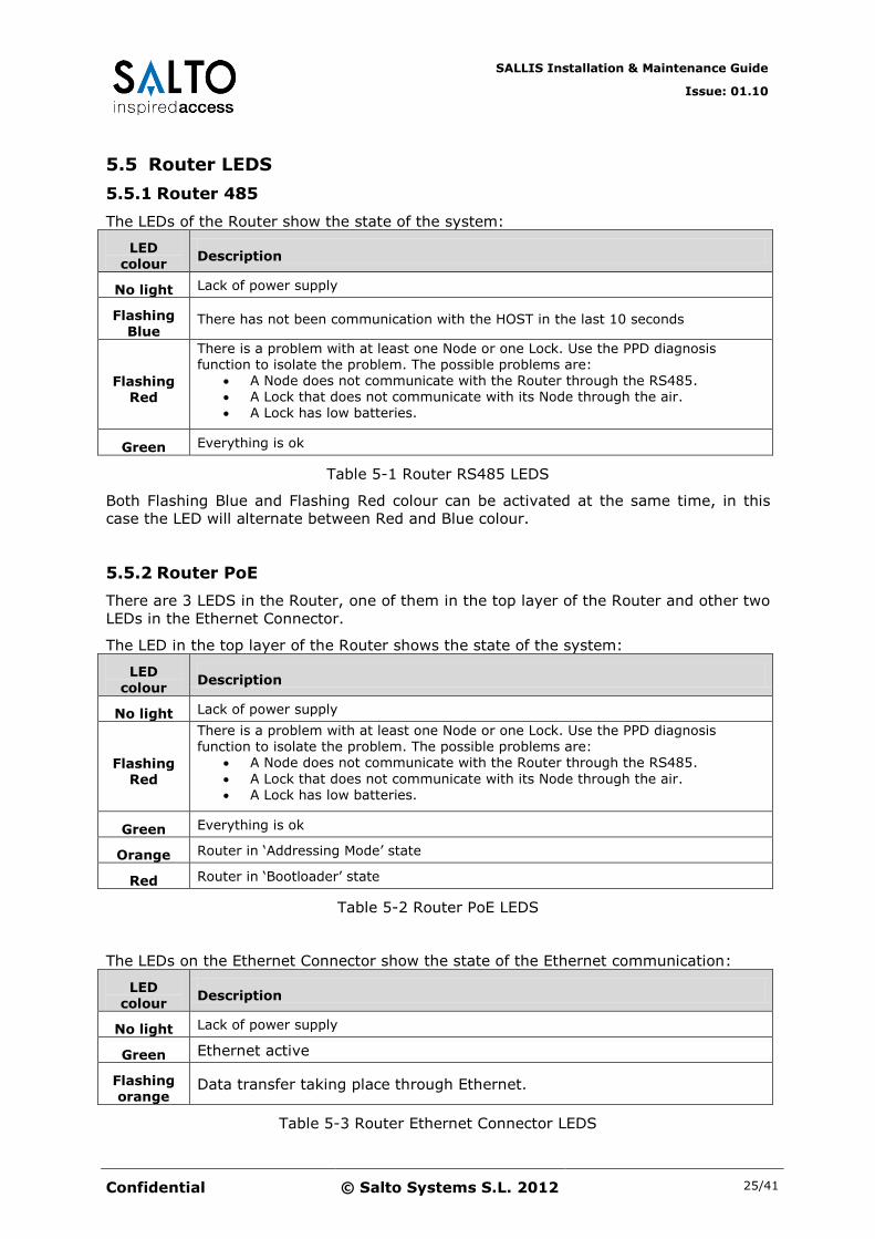
5.5 Router LEDS
5.5.1 Router 485
The LEDs of the Router show the state of the system:
LED colour
Description
No light Lack of power supply
Flashing Blue
There has not been communication with the HOST in the last 10 seconds
Flashing Red
There is a problem with at least one Node or one Lock. Use the PPD diagnosis function to isolate the problem. The possible problems are:
A Node does not communicate with the Router through the RS485. A Lock that does not communicate with its Node through the air.
A Lock has low batteries.
Green Everything is ok
Table 5-1 Router RS485 LEDS
Both Flashing Blue and Flashing Red colour can be activated at the same time, in this
case the LED will alternate between Red and Blue colour.
5.5.2 Router PoE
There are 3 LEDS in the Router, one of them in the top layer of the Router and other two
LEDs in the Ethernet Connector.
The LED in the top layer of the Router shows the state of the system:
LED
colour Description
No light Lack of power supply
Flashing Red
There is a problem with at least one Node or one Lock. Use the PPD diagnosis function to isolate the problem. The possible problems are:
A Node does not communicate with the Router through the RS485.
A Lock that does not communicate with its Node through the air. A Lock has low batteries.
Green Everything is ok
Orange Router in ‘Addressing Mode’ state
Red Router in ‘Bootloader’ state
Table 5-2 Router PoE LEDS
The LEDs on the Ethernet Connector show the state of the Ethernet communication:
LED colour
Description
No light Lack of power supply
Green Ethernet active
Flashing orange
Data transfer taking place through Ethernet.
Table 5-3 Router Ethernet Connector LEDS

SALLIS Installation & Maintenance Guide
Issue: 01.10
Confidential © Salto Systems S.L. 2012 26/41
Green and Flashing Orange LEDs could be active at the same time.
5.6 Node LED
The Green LED of the Node indicates that the Node is properly powered.
5.7 Lock LED
Immediately after been the lock updated or initialized with the PPD it will try to
communicate with the Node. A Green light indicates the successful connection and a Red
light indicates that the communication has been impossible.
Every time the lock reads a card will flash an Orange light indicating that it will start the
Request to the Host through the air.
SALLIS Installation & Maintenance Guide
Issue: 01.10
Confidential © Salto Systems S.L. 2012 27/41
6 Router PoE – Host communication setup
6.1 Starting the Router
When ‘Sallis Router PoE’ is delivered to the costumer, it’s programmed to use DHCP. This
means that after power up, the router will try to obtain a dynamic IP address from the
DHCP server of the local net. If there is no DHCP server on the local net, or the
communication fails for any reason, the router will automatically reset after 10 seconds
and try again.
The Internet protocol used for communication between Host and Router is ‘Transmission
Control Protocol’ or TCP, where ‘Sallis Router’ is configured as TCP server and Host
program must be configured by the user as a TCP client.
First of all, before starting any communication, some parameters related to the TCP
socket between Host and Router must be defined by the user.
These configurations will be made through the ‘Router Sallis Web Server’, a web server
implemented on the Router software application.
6.2 Configuration Parameters
In order to access ‘Router Sallis Web Server’, these steps must be followed:
STEP 1: Switch on the Router. After few seconds of starting up, a green led will show
that application is running correctly.
STEP 2: Press the router clear button ‘CLR’ for approximately 5 seconds until the led
changes from green to orange.
STEP 3: Now, the router have entered ‘Addressing mode’ (it can be verified by the
orange colour of the led) and it will remain in this state for 10 minutes.
Note: It can exit this state at anytime by pushing ‘CLR’ button
briefly.
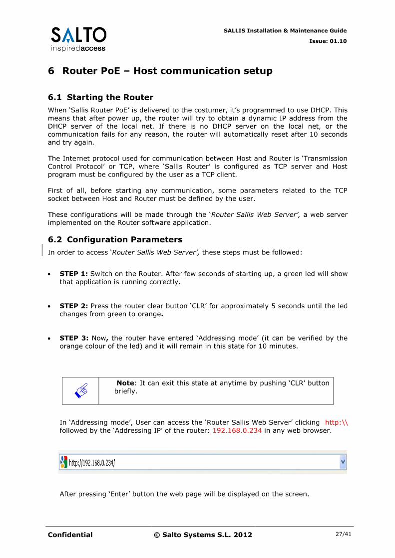
In ‘Addressing mode’, User can access the ‘Router Sallis Web Server’ clicking http:\\
followed by the ‘Addressing IP’ of the router: 192.168.0.234 in any web browser.
After pressing ‘Enter’ button the web page will be displayed on the screen.

SALLIS Installation & Maintenance Guide
Issue: 01.10
Confidential © Salto Systems S.L. 2012 28/41
Figure 6-1 Sallis Router Web Page
At the beginning of the web page, in the upper-left side, we can read the MAC
number of the Router, and just bellow it, there are four different blocks showing all
parameters related to the TCP/IP communication that must be configured.
STEP 4: The first block’s name is ‘Port Configuration’. This parameter refers to the
Router local port used for TCP communication with the Host. The current value of this
parameter can be seen in green colour (1234 by default). In order to change it, write
the new value in the check box bellow with a maximum size of 4 digits.
Figure 6-2 Port Configuration
STEP 5: The second block’s name is ‘DHCP Configuration’. Here, the user can
enabled DHCP client in the router (to obtain a dynamic IP Address) or disabled it. It
is enabled by default.
Figure 6-3 DHCP Configuration

SALLIS Installation & Maintenance Guide
Issue: 01.10
Confidential © Salto Systems S.L. 2012 29/41
STEP 6: Next block’s name is ‘IP static Configuration’. Here, the user can configure
the static IP address, IP gateway and the Net Mask that ‘Sallis Router’ will use in the
local net in case of disabling DHCP.
Figure 6-4 IP Static Configuration
The web page shows in green colour the default value of these parameters. To
change these values the user only needs to define the new values in the white boxes
bellow.
STEP 7: The last block refers to the ‘Router Name’. Here the user can configure a
name for the router that will only be used when DHCP is enabled. The Host will use
this name to easily address the router in the local net. User can change it to any
alphanumeric name desired, with a maximum size of 30 characters. The procedure to
change this name is the same as usual: type the new name in the check box bellow.
Figure 6-5 Router Name
STEP 8: After fulfilling all the form, it is mandatory to push ‘Send’ button in order to
send all the new values to the router, otherwise no-changes will be made to the
previous configuration.

SALLIS Installation & Maintenance Guide
Issue: 01.10
Confidential © Salto Systems S.L. 2012 30/41
The router, after receiving all the data, will show this feedback message in the
screen:
Figure 6-6 Feedback message
And 2 seconds later, it will leave ‘Addressing mode’ status and will restart with the
new configuration. This way, the web server won’t be available again until ‘CLR’
button is pressed.
If any error has been made during configuration, the user can always push ‘Clear’ (in
the web page) to erase all the changes made.
Note: If neither ‘Send’ nor ‘Clear’ buttons are pressed during
10 minutes, the router will automatically reset and start again
with the previously configured parameter values. This is a
security measure, as it will be considered that ‘CLR’ button has
been pressed accidentally in the router.
6.3 Create a Socket
Now that all parameters required for communication have been configured, it’s time for
the host to connect to the router.
The communication starts as follows: After power up, the router (TCP server) binds to
the previously configured port and opens it for connections. Once this step is completed,
(5 seconds approximately) it remains in a listen state waiting for a unique connection
coming from any IP. Now, the TCP client (the Host) must initiate and active open
sending a SYN command from his local port to the router port and IP. This will be the
beginning of the TCP protocol for a connection establishment.

SALLIS Installation & Maintenance Guide
Issue: 01.10
Confidential © Salto Systems S.L. 2012 31/41
Figure 6-5 TCP Communication Establishment
When the connection is established, a communication socket will have been created
between both ports, and any of two sides could start now sending ‘Sallis Protocol
Commands’.
Note: In some cases (an update via PPD or web server, or an
accidental power down of the installation) a reset could be caused
in the router and the current connexion will not be available any
more. For these situations, it’s advisable for the host to send
periodically a ‘diagnostic’ command to the router in order to see if
it’s always answering. If it doesn’t, the host should try to reconnect
again to the router.

SALLIS Installation & Maintenance Guide
Issue: 01.10
Confidential © Salto Systems S.L. 2012 32/41
7 Lock in pre-installation mode
7.1 Introduction
There may be the case where at the time Sallis Locks are installed in doors the wireless
infrastructure is not set yet. For those cases, in order to make the locks operational,
they can be ‘pre-installed’.
7.2 How to proceed
STEP1. In SALLIS application, create a Node with Mac Address 0x000000
STEP2. Configure all locks we want to work in pre-installed mode selecting the Node
with the MAC Address 0x000000
STEP3. Proceed with the initialization of the lock as described in the corresponding
chapter in this document.
7.3 Lock behaviour
Once the lock has been initialized in this specific mode the lock will open to any badge
which can be read according to the ‘INSTALLATION DATA’ parameters (see ‘IDCodeSize‘
in Table 4-1) and any of the Card configurations included in the Router file (see chapter
‘Add New Card’).
SALLIS Installation & Maintenance Guide
Issue: 01.10
Confidential © Salto Systems S.L. 2012 33/41
8 System maintenance
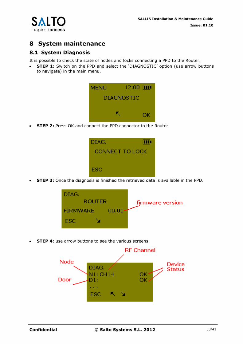
8.1 System Diagnosis
It is possible to check the state of nodes and locks connecting a PPD to the Router.
STEP 1: Switch on the PPD and select the ‘DIAGNOSTIC’ option (use arrow buttons
to navigate) in the main menu.
STEP 2: Press OK and connect the PPD connector to the Router.
STEP 3: Once the diagnosis is finished the retrieved data is available in the PPD.
STEP 4: use arrow buttons to see the various screens.
SALLIS Installation & Maintenance Guide
Issue: 01.10
Confidential © Salto Systems S.L. 2012 34/41
Node List of existing nodes (from N1 up to N16)
Door List of existing nodes (from D1 up to D16)
RF channel The RF channel in which the specific node is operating (from CH11 up to CH26)
Device Status OK: device is working properly.
NO Comm: the device does not communicate
No PAN: the node is not initialized
Low Battery: batteries in the lock are low.
Table 8-1 Diagnosis info screen data.
8.2 Router replacement.
If a Router needs to be replaced:
STEP 1: Physically replace the Router.
STEP 2: Initialise the new Router with exactly the same data as the replaced one:
connect PPD to the new Router, select the Router in the list and run ‘Update’ option.
STEP 3: Update all locks. Connect the PPD to the locks. The Update process is
automatic.
Note: The replacement of a Router involves updating all the locks
of that specific network.
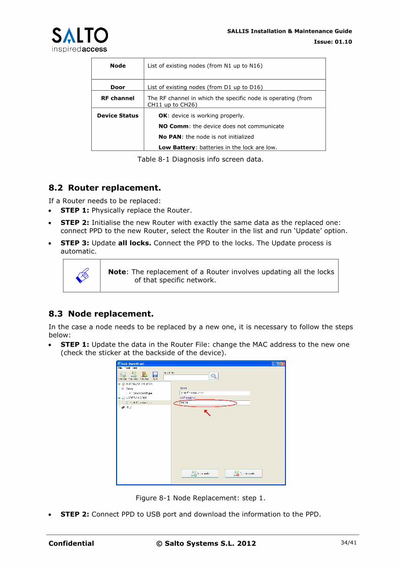
8.3 Node replacement.
In the case a node needs to be replaced by a new one, it is necessary to follow the steps
below:
STEP 1: Update the data in the Router File: change the MAC address to the new one
(check the sticker at the backside of the device).
Figure 8-1 Node Replacement: step 1.
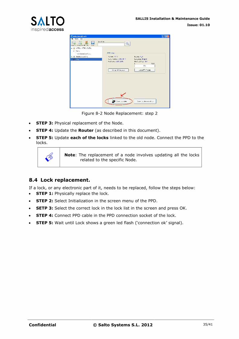
STEP 2: Connect PPD to USB port and download the information to the PPD.
SALLIS Installation & Maintenance Guide
Issue: 01.10
Confidential © Salto Systems S.L. 2012 35/41
Figure 8-2 Node Replacement: step 2
STEP 3: Physical replacement of the Node.
STEP 4: Update the Router (as described in this document).
STEP 5: Update each of the locks linked to the old node. Connect the PPD to the
locks.
Note: The replacement of a node involves updating all the locks
related to the specific Node.
8.4 Lock replacement.
If a lock, or any electronic part of it, needs to be replaced, follow the steps below:
STEP 1: Physically replace the lock.
STEP 2: Select Initialization in the screen menu of the PPD.
SETP 3: Select the correct lock in the lock list in the screen and press OK.
STEP 4: Connect PPD cable in the PPD connection socket of the lock.
STEP 5: Wait until Lock shows a green led flash (‘connection ok’ signal).

SALLIS Installation & Maintenance Guide
Issue: 01.10
Confidential © Salto Systems S.L. 2012 36/41
9 Lock Firmware Update
9.1 Introduction
The Sallis Application together with the PPD offers the device firmware update feature. It
is possible to update the firmware of the following 3 electronic modules within a lock:
Device
Number
Description
Reader 00-08 Mifare reader Module
RF Module 00-38 RF communication Module
Control 00-61 Lock main Control
Table 9-1 Electronic modules within a lock and Device Numbers
9.2 Firmware Diagnostic
It is possible to check the version of each module inside a lock.
STEP 1: Switch on the PPD and select ‘FIRMWARE DIAGNOSTIC’ option in main
menu (use arrow buttons) and press ‘OK’.
STEP 2: Press OK and connect the PPD connector to the lock.
STEP 3: Different modules firmware versions are displayed. Use arrow buttons to see
them all.
SALLIS Installation & Maintenance Guide
Issue: 01.10
Confidential © Salto Systems S.L. 2012 37/41
See Table 9-1 for information on ‘Device Number’.
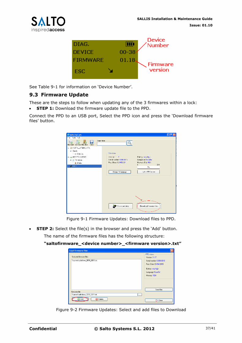
9.3 Firmware Update
These are the steps to follow when updating any of the 3 firmwares within a lock:
STEP 1: Download the firmware update file to the PPD.
Connect the PPD to an USB port, Select the PPD icon and press the ‘Download firmware
files’ button.
Figure 9-1 Firmware Updates: Download files to PPD.
STEP 2: Select the file(s) in the browser and press the ‘Add’ button.
The name of the firmware files has the following structure:
“saltofirmware_<device number>_<firmware version>.txt”
Figure 9-2 Firmware Updates: Select and add files to Download
SALLIS Installation & Maintenance Guide
Issue: 01.10
Confidential © Salto Systems S.L. 2012 38/41
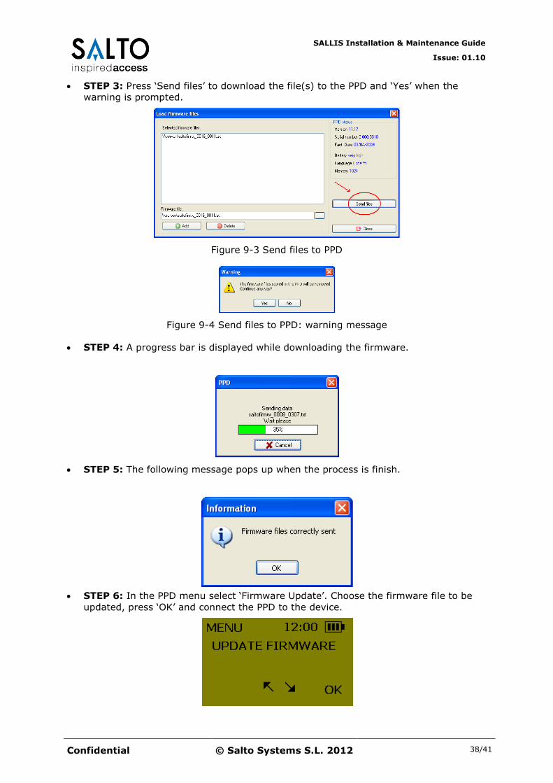
STEP 3: Press ‘Send files’ to download the file(s) to the PPD and ‘Yes’ when the
warning is prompted.
Figure 9-3 Send files to PPD
Figure 9-4 Send files to PPD: warning message
STEP 4: A progress bar is displayed while downloading the firmware.
STEP 5: The following message pops up when the process is finish.
STEP 6: In the PPD menu select ‘Firmware Update’. Choose the firmware file to be
updated, press ‘OK’ and connect the PPD to the device.

SALLIS Installation & Maintenance Guide
Issue: 01.10
Confidential © Salto Systems S.L. 2012 39/41
10 PPD Firmware Update
10.1 Current version
The current version number of a PPD is display for 2 seconds each time a PPD is
switched on.
10.2 Firmware Update
It is possible to update the firmware of the PPD itself. These are the steps to follow:
STEP 1: Connect the PPD to an USB port, Select the PPD icon and press the
button.
Figure 10-1 Update PPD firmware
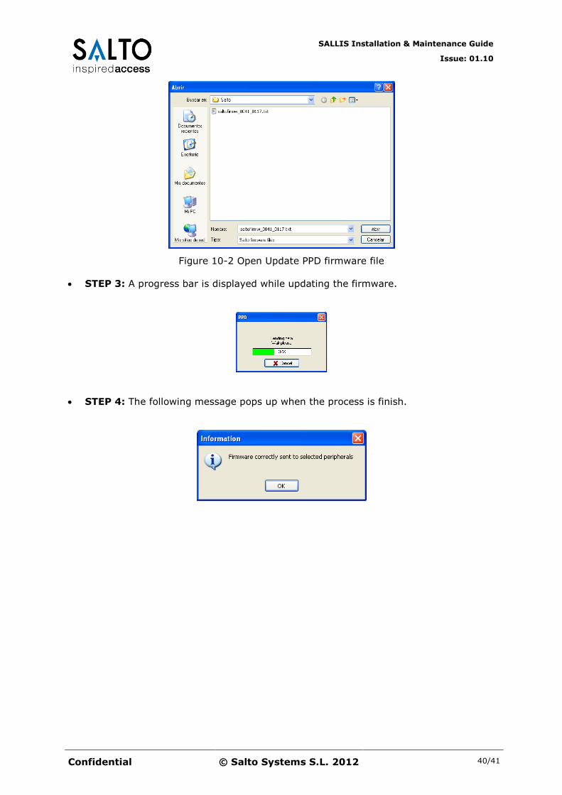
STEP 2: Choose the firmware file (only valid files are displayed)
SALLIS Installation & Maintenance Guide
Issue: 01.10
Confidential © Salto Systems S.L. 2012 40/41
Figure 10-2 Open Update PPD firmware file
STEP 3: A progress bar is displayed while updating the firmware.
STEP 4: The following message pops up when the process is finish.
SALLIS Installation & Maintenance Guide
Issue: 01.10
Confidential © Salto Systems S.L. 2012 41/41
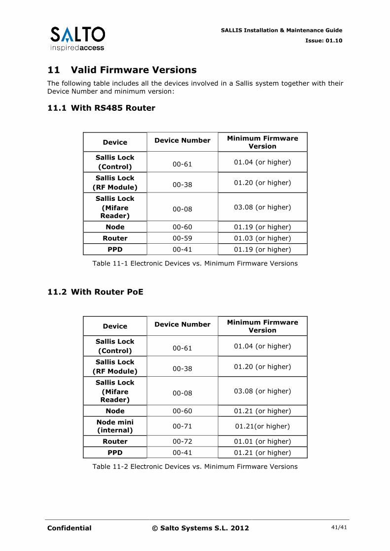
11 Valid Firmware Versions
The following table includes all the devices involved in a Sallis system together with their
Device Number and minimum version:
11.1 With RS485 Router
Device Device Number Minimum Firmware
Version
Sallis Lock
(Control) 00-61 01.04 (or higher)
Sallis Lock
(RF Module) 00-38 01.20 (or higher)
Sallis Lock
(Mifare Reader)
00-08 03.08 (or higher)
Node 00-60 01.19 (or higher)
Router 00-59 01.03 (or higher)
PPD 00-41 01.19 (or higher)
Table 11-1 Electronic Devices vs. Minimum Firmware Versions
11.2 With Router PoE
Device Device Number Minimum Firmware
Version
Sallis Lock
(Control) 00-61 01.04 (or higher)
Sallis Lock
(RF Module) 00-38 01.20 (or higher)
Sallis Lock
(Mifare
Reader) 00-08 03.08 (or higher)
Node 00-60 01.21 (or higher)
Node mini
(internal) 00-71 01.21(or higher)
Router 00-72 01.01 (or higher)
PPD 00-41 01.21 (or higher)
Table 11-2 Electronic Devices vs. Minimum Firmware Versions