saliency ratio and power factor of ipm motors optimally
TRANSCRIPT

Marquette Universitye-Publications@MarquetteElectrical and Computer Engineering FacultyResearch and Publications
Electrical and Computer Engineering, Departmentof
11-1-2016
Saliency Ratio and Power Factor of IPM MotorsOptimally Designed for High Efficiency and LowCost ObjectivesPeng ZhangGeneral Motors
Dan M. IonelUniversity of Wisconsin - Milwaukee
Nabeel DemerdashMarquette University, [email protected]
Accepted version. IEEE Transactions on Industry Applications, Vol. 52, No. 6 (November/December2016): 4730-4739. DOI. © 2016 Institute of Electrical and Electronic Engineers (IEEE). Used withpermission.

Marquette University
e-Publications@Marquette
Electrical and Computer Engineering Faculty Research and Publications/College of Engineering
This paper is NOT THE PUBLISHED VERSION; but the author’s final, peer-reviewed manuscript. The published version may be accessed by following the link in th citation below.
IEEE Transactions on Industry Applications ( Volume: 52 , Issue: 6 , Nov.-Dec. 2016 ), 4730-4739. DOI. This article is © Institute of Electrical and Electronic Engineers (IEEE) and permission has been granted for this version to appear in e-Publications@Marquette. Institute of Electrical and Electronic Engineers (IEEE) does not grant permission for this article to be further copied/distributed or hosted elsewhere without the express permission from Institute of Electrical and Electronic Engineers (IEEE).
Saliency Ratio and Power Factor of IPM Motors With Distributed Windings Optimally Designed for High Efficiency and Low-Cost Applications
Peng Zhang General Motors, Pontiac, MI Dan M. Ionel University of Wisconsin–Milwaukee, WI Nabeel A. O. Demerdash Marquette University, Milwaukee, WI
Abstract: This paper uses formal mathematical optimization techniques based on parametric finite-element-based computationally efficient models and differential evolution algorithms. For constant-power applications, in the

novel approach described, three concurrent objective functions are minimized: material cost, losses, in order to ensure high efficiency, and the difference between the rated and the characteristic current, aiming to achieve very high constant-power flux-weakening range. Only the first two objectives are considered for constant-torque applications. Two types of interior permanent magnet rotors in a single- and double-layer V-shaped configuration are considered, respectively. The stator has the typical two slots per pole and phase distributed winding configuration. The results for the constant-torque design show that, in line with expectations, high efficiency and high power factor machines are more costly, and that the low-cost machines have poorer efficiency and power factor and most importantly, and despite a common misconception, the saliency ratio may also be lower in this case. For constant-power designs, the saliency ratio can be beneficial. Nevertheless, despite a common misconception, when cost is considered alongside performance as an objective, a higher saliency ratio does not necessarily improve the power factors of motors suitable for ideal infinite flux weakening.
SECTION I. Introduction Permanent magnet (PM) synchronous motors have been established as a technology for high-efficiency applications, including constant and variable torque drives for servos, pumps, fans, and compressors. Furthermore, the latest developments in hybrid and/or electric vehicles (HEV/EV) incentivize the research activities for the design optimization of PM machines. For such traction applications, PM machines need to have high torque and power density, high efficiency over wide constant-power speed range (CPSR), and intermittent overload operating capabilities [1]. In particular, interior PM (IPM) motors of the type with distributed windings studied in the current paper or with concentrated windings represent a strong candidate solution for such applications, e.g., [2]– [7].
Design optimization techniques for electric machines have been reviewed by Duan and Ionel, who have also proposed a PM motor design benchmark [8]. For the multiobjective optimization of IPM machines, Jung et al. have proposed the use of the Kriging surrogate modeling method in order to reduce the computational time [9]. The application of scaling modeling, another popular machine design technique, for vehicle applications was investigated by Filipi et al.[10]. Other authors have proposed design optimization techniques that consider the driving cycles for traction applications, e.g., [7],[11]– [20]. Early work published by Higaki et al. comparatively studied single and double layers IPMs under the condition of constant PM volume [11]. Jahns et al. focused their research on the impact of IPM rotor variations on the key motor performance metrics [12]. The application of surface PM (SPM) machines for HEV/EV motor drives has been investigated by Yuan et al. [13]–[15].
A coupled electromagnetic and thermal model has been developed by Jiang and Jahns for the fast calculation of the maximum current density allowed during the machine's transient operation with applications to a 12-slot 10-pole SPM design [14]. Such a stator slot–pole combination employed in conjunction with a spoke rotor has been proposed by Galioto et al. in order to meet the Freedom CAR 2020 specifications [16]. Spoke-type motors with ferrites were considered by Long et al. in order to achieve high efficiency and meet low-cost requirements [19]. Recently, Morandin et al. investigated the use of PM-assisted synchronous reluctance machines for traction application considering two U.S. driving cycles [20].
In terms of engineering implementations, Bae et al. presented the design and performance of the electric propulsion system for GM's second-generation extended range electric vehicle [17]. Bayrak et al.proposed a method that integrates a high-fidelity motor and vehicle model for optimizing the IPM motor and vehicle propulsion design simultaneously, with limited motor-independent variables [18].
The basic principle of computationally efficient finite-element analysis (CE-FEA) method was first presented by Ionel and Popescu [21], and was later expanded by Sizov et al. [22], [23]. This CE-FEA method was combined
with a differential evolution (DE) algorithm [24], [25] in order to perform automatic design optimization with multiple objectives for PM machines with different combinations of slots, poles, and rotor geometries for various applications [22], [23],[26]–[28]. In these previous design optimization studies, only the maximum torque per ampere (MTPA) operating point was taken into account. Such constant-torque operating performance is typically sufficient for motor designs for general industrial applications.
Differing from the previous work, this paper expands the design optimization techniques for studying constant-torque and constant-power applications. In the current paper, the extended speed operation capability was considered as an objective for the DE design optimization algorithm. This new design optimization approach was implemented for the case studies of IPM machines with single-layer (SL) and double-layer (DL) PM layouts. Finally, a comparison between these two IPM machine configurations was performed.
The optimization procedure presented in this paper focuses on the rated performance at constant speed and torque operation or at corner/base speed for constant-power applications. More complex operating conditions, which consider, for example, a full driving cycle or multiple speed and torque combinations, may result in different results and trends, and are the object of the authors on-going research that will be reported in future papers.
SECTION II. IPM Machines for Constant-Power Applications The typical operation capabilities of IPM machines can be described by the torque–speed and power–speed curves/envelops, which are shown in Fig. 1. These capabilities are generally determined by the machine's parameter values as well as the limits on the voltage and current from the motor drive system [6], [29] –[32]. In Fig. 1, Region I, below the base speed 𝜔𝜔𝑏𝑏, the motor is operating in the constant-torque range using the MTPA control method, where the maximum torque is limited by the maximum stator current. When the motor runs above the base speed, Region II, the drive operating regime is commonly referred to as the flux-weakening control to achieve the constant-power operation, where the limits on the voltage and currents from the drive become important factors. Once reaching the maximum affordable speed 𝜔𝜔𝑐𝑐, Region III, for the constant-power operation, the machine will operate with reduced power and reduced torque in an extended speed range. This extended speed range in Region III of Fig. 1 requires that the machine's characteristic current 𝐼𝐼ch should be lower than or equal to the rated phase current 𝐼𝐼𝑛𝑛 supplied from the drive source. The characteristic current is defined as
𝐼𝐼ch = 𝜆𝜆pm/𝐿𝐿𝑑𝑑 (1)
where 𝜆𝜆pm is the PM's flux linkage amplitude in Webers, and 𝐿𝐿𝑑𝑑 is the d-axis inductance. This characteristic current is the center point of the voltage limit ellipse shown in Fig. 2. The voltage limit equation in the dq-axes current plane, 𝑖𝑖𝑑𝑑 and 𝑖𝑖𝑞𝑞, is given as follows [5]:
(𝑖𝑖𝑑𝑑 + 𝐼𝐼ch)2 + (𝐿𝐿𝑞𝑞𝐿𝐿𝑑𝑑
)2𝑖𝑖𝑞𝑞2 = 𝑉𝑉max2
𝐿𝐿𝑑𝑑2𝜔𝜔𝑒𝑒
2 (2)
where 𝑉𝑉max is the peak value of the rated phase voltage and 𝜔𝜔𝑒𝑒 is the electrical angular speed. With the implementation of space vector pulse-width modulation (PWM), the maximum phase voltage 𝑉𝑉max can be estimated as 𝜂𝜂𝑉𝑉dc/√3 [30]. Here, 𝑉𝑉dc is the dc-link voltage, and the ratio η can be between 0.9 and 0.95 for the consideration of the voltage reduction caused by the dead time of the inverter. The relationship 𝐼𝐼ch ≤ 𝐼𝐼𝑛𝑛 can be seen from Fig. 2, where the current trajectory for the MTPA and flux-weakening operation is also shown. One should notice that when 𝐼𝐼ch ≤ 𝐼𝐼𝑛𝑛, the power delivery capability of the IPM machine will be reduced [31].

Fig. 1. Torque–speed and power–speed curves for constant torque and constant power applications. Solid: torque (left y-axis); dash: power (right y-axis).
Fig. 2. Trajectory of the current vector for MTPA and flux-weakening operations.
Thus, the key condition for IPM machines in order to achieve wide speed ranges is 𝐼𝐼ch = 𝐼𝐼𝑛𝑛 [32] , where 𝐼𝐼𝑛𝑛 is generally decided by the thermal limit of the inverter and the motor. This property requirement for constant-power machines is considered as one of the design objectives for the DE algorithm in the design optimization studies presented in this paper. It is acknowledged that the focus on matching the requirements for very high CPSR values is naturally favoring designs for which the difference between the characteristic current and the rated current is as small as possible, while for some practical applications, smaller values of CPSR may be acceptable.
SECTION III. Parametric Models for 36-Slot 6-Pole IPM Machines In this paper, two robust parametric geometric models were developed for a three-phase stator with distributed winding and two slots per pole and phase, exemplified in a 36-slot 6-pole configuration, and two IPM rotors with SL and DL PM layouts, respectively. The cross section and the definition of the geometric variables for the models is shown in Fig. 3. The SL-IPM topology has the same geometric definitions as the DL-IPM configuration without the top layer PM layout. The design variables and the corresponding variable ranges are defined in Table I. In this table, the last two design variables are only suitable for the DL-IPM case study. The stator outer diameter and rotor inner (shaft) diameter are fixed for all designs. The width of the bridge between the magnet cavities and rotor outer surface is constant at the minimum values that are suitable for high volume manufacturing and mechanical strength. Based on the same considerations, the bridge width between the two wings of the magnet cavities in one pole is also constant.

Fig. 3. Parametric model of a three-phase 36-slot 6-pole IPM machine with a double-layer PM rotor configuration.
TABLE I Definition and Ranges of Design Variables for SL-IPM (Top 10 Variables) and DL-IPM (12 Variables)
Design variables Definition Min Max k si D si /D so 0.55 0.7 hg air gap height [mm] 1 2.5 k wT αw t/αs 0.35 0.55 dY yoke thickness [mm] 13.0 25.0 k ti p tooth tip angle ratio 0.3 0.8 k dpm PM depth ratio 0.2 0.5 k wpm w pm /w pm ma x 0.8 0.93 h pm PM height [mm] 3.8 9.0 k wq q-axis bridge ratio 0.2 0.7 τp pole arc [degree] 35 50 k tapm top PM angle ratio 0.2 0.8 k thpm top PM height ratio 0.2 0.8
In order to avoid the geometry conflicts in the design optimization procedure, design variables were defined using the ratio expressions as also given in Table I. Here, 𝑘𝑘si is the split ratio between the stator inner diameter 𝐷𝐷siand stator outer diameter 𝐷𝐷so, while 𝑘𝑘wT is the ratio between the tooth width central angle 𝛼𝛼wT and the slot arc central angle 𝛼𝛼𝑠𝑠 = 360 ∘/𝑁𝑁𝑠𝑠 𝑁𝑁𝑠𝑠: number of slots). The tooth tip ratio 𝑘𝑘tip is defined as (1 − 𝛼𝛼so
𝛼𝛼𝑠𝑠−𝛼𝛼wt), where 𝛼𝛼so is the central angle of the slot opening width. The parameter 𝑘𝑘𝑑𝑑pm is the PM depth

ratio 𝑑𝑑pm/(𝑅𝑅ro − 𝑅𝑅ri) , where 𝑅𝑅ro and 𝑅𝑅ri are the rotor outer and inner radii, respectively. The ratios 𝑘𝑘wq, 𝑘𝑘tapm, and 𝑘𝑘thpm are obtained by their true values divided by the maximum possible values limited by the other geometry parameters. 𝑘𝑘wq = 𝑤𝑤𝑞𝑞/𝑤𝑤𝑞𝑞max, where 𝑤𝑤qmax = 𝑅𝑅1sin (𝜋𝜋/6 −𝑚𝑚𝑚𝑚𝑚𝑚(∠1,∠2)). Here, 𝑅𝑅1 is the radius of point 1 in Fig. 3, ∠1 and ∠2 are the rotating angles of the points 1 and 2 relative to the x-axis. The top PM angle ratio 𝑘𝑘tapm = ∠3/(𝛼𝛼pm/2) is used to decide the position of point 3 in Fig. 3. The top PM height ratio kthpm=(x6−x5)/(x6−x4) is used to calculate the height of the top PM segment. Here, 𝑚𝑚4, 𝑚𝑚5, and 𝑚𝑚6 are the x-axis coordinate values of points 4, 5, and 6 in Fig. 3.
The remanent flux density of the PM material is 1.1 T. The laminated core is made out of M19G29 silicon steel with a thickness of 0.35 mm. During the multiobjective optimization for minimum losses and minimum cost, the current density in the stator winding was fixed to the high value of 9.3 A/mm2, which ensures high electric loading and hence high specific power, and was established based on the manufacturer's engineering knowhow for the specific application.
All the designs considered in the optimization study are rated for an output power of 500 hp. This is achieved by considering the axial length as a dependent variable. During the optimization, an initial core length is set, the independent variables associated with the cross-sectional geometry are varied and the torque is calculated based on CE-FEA. The axial length is then proportionally scaled such that the output torque of the design is equal to the rated values. This procedure leads to different values of the axial length for each individual design as exemplified later in this paper.
SECTION IV. Design Specification for DE Algorithm The multiobjective design optimization of these IPM machines requires that the DE method should be used to search for the optimized machines. The performance of such machines gives minimized total losses and cost, wider operating speed range, lower torque ripple, as well as higher power factor while preventing the danger of irreversible demagnetization of the PMs under rated load condition. One way to achieve this is by considering three objectives given by the following expressions.
1. Minimize losses: 𝑃𝑃loss = 𝑃𝑃Fe + 𝑃𝑃Cu. 2. Minimize the material cost: Cost = 25𝑚𝑚pm + 3𝑚𝑚Cu + 1𝑚𝑚Fe. 3. Maximize the speed range by minimizing the absolute current difference between the rated current and
characteristic current, which is |𝐼𝐼dif| = | 𝐼𝐼rated−𝐼𝐼ch
𝐼𝐼ch|, where 𝑃𝑃Fe and 𝑃𝑃Cu are the stator core losses and
copper losses, respectively, 𝑚𝑚pm, 𝑚𝑚cu, and 𝑚𝑚Fe are the masses of PMs, copper, and steel materials, respectively.
In the cost function, the specific cost of laminated steel is set up as the base (unity) value for all materials and the cost ratios considered are typical values for high volume production.
Meanwhile, the torque ripple, fundamental power factor, and minimum flux density in the PMs are defined as constraints as follows.
1. The torque ripple under the rated load condition 𝑚𝑚𝑚𝑚𝑚𝑚(𝑇𝑇𝑒𝑒)−𝑚𝑚𝑚𝑚𝑛𝑛(𝑇𝑇𝑒𝑒)average(𝑇𝑇𝑒𝑒)
≤ 20%.
2. The fundamental power factor cos (𝜃𝜃) ≥ 0.7, where 𝜃𝜃 is the phase shift between the fundamental voltage and current, as shown in Fig. 4.
3. Minimum flux density in PMs under the rated load condition 𝐵𝐵min ≥ 0.3𝐵𝐵𝑟𝑟, where for the PM's retentivity 𝐵𝐵𝑟𝑟 = 1.1𝑇𝑇..

Fig. 4. Phasor diagram for PM synchronous machines.
These constraints were utilized for the selection of the optimum designs for each generation of the DE algorithm, including the final one.
Motor performance is estimated at rated operation, which for constant-power applications corresponds to the corner/base speed. For practical designs with the configuration and dimensions studied, segmented magnets, typical PWM switching frequency, and the total rotor losses in the PMs and steel do not exceed 10% of the total motor losses, and in order to reduce the computational effort, these losses have not been considered in the large-scale optimization study, which hence focused on the stator losses. The optimization process only explored IPM machine designs with distributed winding stators and with two slots-per-pole-per-phase in a 36-slot and 6-pole configuration.
In the automatic design optimization, the DE algorithm is utilized to generate a set of candidate designs, which are transferred to the CE-FEA to estimate the torque profiles, stator core losses, copper losses, the induced voltage profiles, material costs, resistance and inductance values, characteristic currents, as well as power factors all at rated operation [21], [22]. The core losses are calculated based on the harmonic contributions following the procedure previously developed and published by the authors’ research group [21], [22].
The design optimization problem in this paper is dealing with three objectives and three constraints, which complicates the selection criteria for best designs. When there are many constraints, the main drawback of the penalty approach is that prespecified weights must be well chosen to keep the population from converging upon either unfeasible or nonoptimal vectors. Overpenalizing with large penalty weights typically speeds convergence to a feasible solution, but risks prematurely converging on a suboptimal one, especially during the optimization's early stages. Because weight selection tends to be a trial and error optimization problem, simpler direct constraint handling methods (e.g., Lampinen's criterion [24]) are more suitable for multiobjective and multiconstraint optimization problems in this paper. The detailed explanation of the Lampinen's criterion is described by the pseudocode expression (3) in one of the authors’ previously published papers [27].
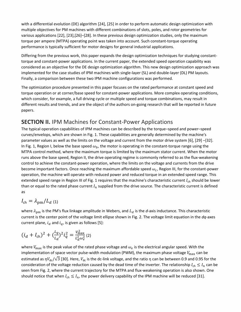
SECTION V. Design Optimization Results A. SL-IPM Machines for Constant-Torque Applications In the design optimization for constant-torque applications, only loss and material cost objectives were considered. The DE algorithm generated 3500 designs with 70 designs per generations and a total of 50 generations, and the corresponding results are shown in the scatter plots in Figs. 5 and 6. In these two figures, the color maps represent the fundamental power factors and saliency ratios of those generated designs. Here,
the saliency ratio is defined as 𝐿𝐿𝑞𝑞/𝐿𝐿𝑑𝑑. The d- and q-axes inductances 𝐿𝐿𝑑𝑑 and 𝐿𝐿𝑞𝑞 were calculated at rated operation from Park's transformation of three-phase self- and mutual inductances [33]. The base value for the cost is defined with reference to the unity value design, which is a part of the Pareto front identified in Fig. 5, and for the losses is 6000 W. To ensure a general basis for comparison, this per unit (p.u.) system is employed throughout this paper.
Fig. 5. Losses, material cost, and fundamental power factor for SL-IPM machines in constant-torque applications. The black solid curve shows the Pareto front.
Fig. 6. Losses, material cost, and saliency ratio for SL-IPM machines in constant-torque applications.
The results for the constant-torque design show that, in line with expectations, high efficiency and high power factor machines are more costly, and that the low-cost machines have poorer efficiency and power factor and most importantly, and despite a common misconception, the saliency ratio can also be lower in this case.
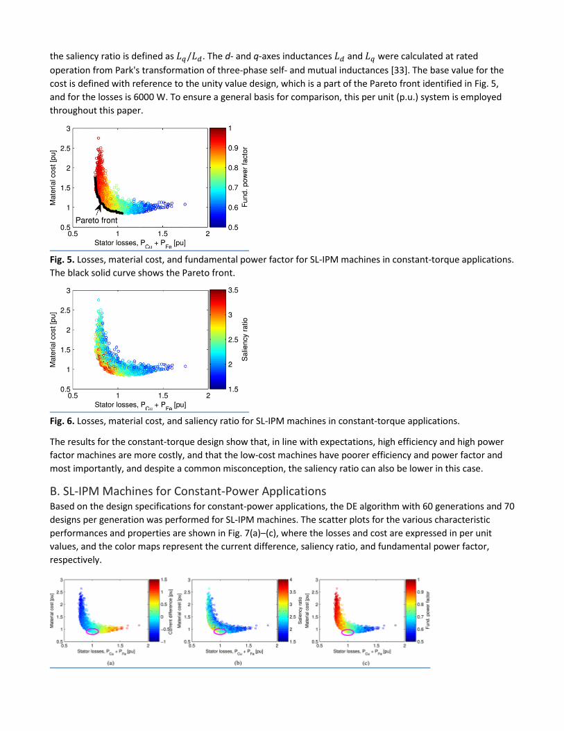
B. SL-IPM Machines for Constant-Power Applications Based on the design specifications for constant-power applications, the DE algorithm with 60 generations and 70 designs per generation was performed for SL-IPM machines. The scatter plots for the various characteristic performances and properties are shown in Fig. 7(a)–(c), where the losses and cost are expressed in per unit values, and the color maps represent the current difference, saliency ratio, and fundamental power factor, respectively.
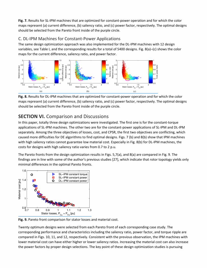
Fig. 7. Results for SL-IPM machines that are optimized for constant-power operation and for which the color maps represent (a) current difference, (b) saliency ratio, and (c) power factor, respectively. The optimal designs should be selected from the Pareto front inside of the purple circle.
C. DL-IPM Machines for Constant-Power Applications The same design optimization approach was also implemented for the DL-IPM machines with 12 design variables, see Table I, and the corresponding results for a total of 5400 designs. Fig. 8(a)–(c) shows the color maps for the current difference, saliency ratio, and power factor.
Fig. 8. Results for DL-IPM machines that are optimized for constant-power operation and for which the color maps represent (a) current difference, (b) saliency ratio, and (c) power factor, respectively. The optimal designs should be selected from the Pareto front inside of the purple circle.
SECTION VI. Comparison and Discussions In this paper, totally three design optimizations were investigated. The first one is for the constant-torque applications of SL-IPM machines. The other two are for the constant-power applications of SL-IPM and DL-IPM separately. Among the three objectives of losses, cost, and CPSR, the first two objectives are conflicting, which caused more difficulties for DE algorithms to find optimal designs. Figs. 7 (b) and 8(b) show that IPM machines with high saliency ratios cannot guarantee low material cost. Especially in Fig. 8(b) for DL-IPM machines, the costs for designs with high saliency ratio varies from 0.7 to 2 p.u.
The Pareto fronts from the design optimization results in Figs. 5,7(a), and 8(a) are compared in Fig. 9. The findings are in line with some of the author's previous studies [27], which indicate that rotor topology yields only minimal differences in the optimal Pareto fronts.
Fig. 9. Pareto front comparison for stator losses and material cost.
Twenty optimum designs were selected from each Pareto front of each corresponding case study. The corresponding performance and characteristics including the saliency ratio, power factor, and torque ripple are compared in Figs. 10, 11, and 12, respectively. Consistent with the previous observation, the IPM machines with lower material cost can have either higher or lower saliency ratios. Increasing the material cost can also increase the power factors by proper design selections. The key point of these design optimization studies is pursuing

wider operating speed ranges. Thus, optimal designs are located inside the purple circles in all these figures, see Fig. 7 and 8. In Fig. 13(a) and (b), the current differences versus the material costs and total losses are given for 20 designs of SL and DL IPM machines along the Pareto fronts shown in Fig. 9. For constant-power applications, the design objective of the current difference reflects the extended speed range of the machines, for which the target value is zero, see Fig. 13. From Figs. 10 to 13, the difference between the design optimization results for the constant-torque and constant-power applications is summarized in Table II .
Fig. 10. Saliency ratio comparison with (a) material cost and with (b) stator losses.
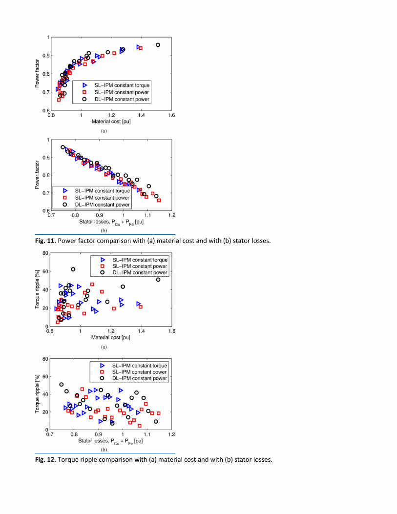
Fig. 11. Power factor comparison with (a) material cost and with (b) stator losses.
Fig. 12. Torque ripple comparison with (a) material cost and with (b) stator losses.
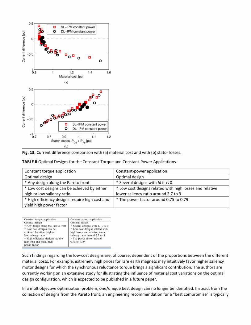
Fig. 13. Current difference comparison with (a) material cost and with (b) stator losses.
TABLE II Optimal Designs for the Constant-Torque and Constant-Power Applications
Constant torque application Constant-power application Optimal design Optimal design * Any design along the Pareto front * Several designs with Id if ∝ 0 * Low cost designs can be achieved by either high or low saliency ratio
* Low cost designs related with high losses and relative lower saliency ratio around 2.7 to 3
* High efficiency designs require high cost and yield high power factor
* The power factor around 0.75 to 0.79
Such findings regarding the low-cost designs are, of course, dependent of the proportions between the different material costs. For example, extremely high prices for rare earth magnets may intuitively favor higher saliency motor designs for which the synchronous reluctance torque brings a significant contribution. The authors are currently working on an extensive study for illustrating the influence of material cost variations on the optimal design configuration, which is expected to be published in a future paper.
In a multiobjective optimization problem, one/unique best design can no longer be identified. Instead, from the collection of designs from the Pareto front, an engineering recommendation for a “best compromise” is typically

made. For each case study, four optimum designs from the Pareto fronts were selected in order to achieve the smallest current difference and hence the widest CPSR. The corresponding geometries are shown in Figs. 15 and 16, respectively, and the main properties of these designs are summarized in Tables III and IV.
TABLE III Main Properties of the Optimal SL-IPM Designs From Fig. 15
SL-IPM (a) (b) (c) (d)
Cost [p.u.] 0.877 0.854 0.877 0.855 Losses [p.u.] 0.989 1.004 1.031 1.046 Current difference [p.u.] 0.114 0.002 0.029 0.065 Fund. power factor [p.u.] 0.78 0.75 0.76 0.73 Torque ripple (skewed) [%] 8.2 6.9 3.0 4.1 Saliency ratio 2.88 2.80 2.77 2.60
Efficiency [%] 98.23 98.2 98.16 98.13 Main geometry Stack length [mm] 228.6 233.6 213.4 238.5 Air gap height [mm] 1.024 1.066 1.056 1.095 Stator inner diameter [mm] 150.52 149.86 148.95 151.96
TABLE IV Main Properties of the Optimal DL-IPM Designs From Fig. 16
DL-IPM (a) (b) (c) (d)
Cost [p.u.] 0.895 0.888 0.873 0.904 Losses [p.u.] 1.009 1.022 1.037 1.056 Current difference [p.u.] 0.174 0.085 0.008 0.107 Fund. power factor [p.u.] 0.80 0.77 0.75 0.77 Torque ripple (skewed) [%] 10.5 5.3 13.6 15.7 Saliency ratio 2.99 2.92 2.69 3.01
Efficiency [%] 98.19 98.17 98.15 98.11 Main geometry Stack length [mm] 204.0 215.2 213.5 204.1 Air gap height [mm] 1.044 1.039 1.060 1.056 Stator inner diameter [mm] 149.72 152.92 144.45 144.65

As part of a comparative study for the Pareto fronts of each of the three optimization problems, the distribution of the main performance indexes, namely, loss, cost, saliency ratio, power factor, torque ripple, and current difference is box plotted in Fig. 14. The average values that were used to define the p.u. system for each optimization problem and to calculate the box plot data as (actual value average)/average are listed in Table V.
Fig. 14. Performance variations for the Pareto front designs of three optimization problems: SL-IPM constant torque (blue—1), SL-IPM constant power (red—2), and DL-IPM constant power (green—3). Values plotted for (a) losses, cost, saliency ratio (SR), and power factor (PF); (b) torque ripple (TR) and current difference (I dif).

Fig. 15. Optimal designs for SL-IPM machines with current difference close to zero. See also Table III.
Fig. 16. Optimal designs for DL-IPM machines with current difference close to zero. See also Table IV.
TABLE V Performance Average Values for the Pareto Fronts of Three Optimization Problems, i.e., SL-IPM Constant Torque (SL-CT), SL-IPM Constant Power (SL-CP), and DL-IPM Constant Power (DL-CP)
Loss [p.u.] Cost [p.u.] SR PF TR[%] Idif[%] SL-CT 0.966 1.149 2.473 0.802 8.1 NA SL-CP 0.975 1.161 2.430 0.790 8.0 −0.141 DL-CP 0.946 1.279 2.723 0.840 9.1 −0.300

The constant-power optimization problems, which include a third objective for the current difference, result in a relatively large range of variation for this objective, meaning that only a few of the designs from the Pareto may actually realize a very small current difference and therefore achieve a very wide power speed range CPSR (see alsoTables IV and V). It is interesting to note from Figs. 13(a) and 14that the designs with very low (close to zero) current difference are also located in the low-cost region providing an indication that the mathematical algorithm actively worked for the fulfilment of multiple objectives.
Reduced torque ripple is a typical requirement for a high performance application. Generally, a torque ripple constraint is conflicting with the objectives of cost and efficiency and a pragmatic engineering approach, especially for IPM machines with distributed windings, is to stagger/step skew the rotor or continuously skew the stator. The first method typically results in a reduction of two to three times of the two-dimensional (2-D) FEA calculated torque, while the second may reduce ripple by up to an order of magnitude. In the study presented in this paper, the torque ripple calculations during the constrained optimization process were performed by 2-D FEA. The results selected from the final Pareto fronts (see Fig. 12) were further postprocessed for a single-stage stagger skew (see Tables III and IV) following the procedure introduced in [34].
It should be noted that, especially for machines designed for constant-power operation, the optimization objectives can be represented by a collection of performance indexes at different operation conditions, for example, at rated (base) and maximum speed, or by a weighted combination over a traction driving cycle, etc. The authors are currently working on such extended optimization formulations, which will be published in future papers.
SECTION VII. Conclusion In this paper, design optimization techniques for distributed winding machines with two types of IPM rotors, in a SL and DL configuration, were investigated for constant-torque or constant-power applications. Only losses and material cost were considered as objectives in the constant-torque design optimization problem. For constant-power applications, three objectives were considered and the IPM machines were designed to achieve wider operating speed ranges, while maintaining high efficiency and low material cost. Based on the ratio parameterized models, an automatic design optimization method using CE-FEA and DE algorithms was implemented. Finally, optimal designs from the Pareto fronts were compared.
One observation from the design optimization studies, conducted on a 36-slot 6-pole configuration and a 500 hp rating, is that IPM machines with high power factor also require high material cost. The relationship between saliency and cost is more intricate. It is also interesting to note that for constant-power applications, IPM machines with high saliency ratios do not necessarily have a wide CPSR.
References 1. Z. Zhu, D. Howe, "Electrical machines and drives for electric hybrid and fuel cell vehicles", Proc. IEEE, vol. 95,
no. 4, pp. 746-765, Apr. 2007. 2. D. Ionel, J. Eastham, T. J. E. Miller, E. Demeter, "Design considerations for permanent magnet synchronous
motors for flux weakening applications", IEE Proc. Elect. Power Appl., vol. 145, no. 5, pp. 435-440, Sep. 1998.

3. P. Reddy, A. EL-Refaie, K.-K. Huh, J. Tangudu, T. Jahns, "Comparison of interior and surface pm machines equipped with fractional-slot concentrated windings for hybrid traction applications", IEEE Trans. Energy Convers., vol. 27, no. 3, pp. 593-602, Sep. 2012.
4. G. Pellegrino, A. Vagati, P. Guglielmi, B. Boazzo, "Performance comparison between surface-mounted and interior PM motor drives for electric vehicle application", IEEE Trans. Ind. Electron., vol. 59, no. 2, pp. 803-811, Feb. 2012.
5. M. Barcaro, N. Bianchi, F. Magnussen, "Permanent-magnet optimization in permanent-magnet-assisted synchronous reluctance motor for a wide constant-power speed range", IEEE Trans. Ind. Electron., vol. 59, no. 6, pp. 2495-2502, Jun. 2012.
6. T. Jahns, "Flux-weakening regime operation of an interior permanent-magnet synchronous motor drive", IEEE Trans. Ind. Appl., vol. IA-23, no. 4, pp. 681-689, Jul. 1987.
7. K. Laskaris, A. Kladas, "Internal permanent magnet motor design for electric vehicle drive", IEEE Trans. Ind. Electron., vol. 57, no. 1, pp. 138-145, Jan. 2010.
8. Y. Duan, D. M. Ionel, "A review of recent developments in electrical machine design optimization methods with a permanent magnet synchronous motor benchmark study", IEEE Trans. Ind. Appl., vol. 49, no. 3, pp. 1268-1275, May/Jun. 2013.
9. S.-Y. Jung, H.-K. Jung, Dong-Kuk Lim, Kyung-Pyo Yi, J.-S. Ro, "Optimal design of an interior permanent magnet synchronous motor by using a new surrogate-assisted multi-objective optimization", IEEE Trans. Magn., vol. 51, no. 11, pp. 1-4, Nov. 2015.
10. Z. Filipi, K. Zhou, A. Ivanco, H. Hofmann, "Finite-element-based computationally efficient scalable electric machine model suitable for electrified powertrain simulation and optimization", IEEE Trans. Ind. Appl., vol. 51, no. 6, pp. 4435-4445, Nov. 2015.
11. T. Higaki, Y. Honda, T. Nakamura, Y. Takeda, "Motor design considerations and test results of an interior permanent magnet synchronous motor for electric vehicles", Proc. 32nd IAS Annu. Meeting Conf. Rec. IEEE Ind. Appl. Conf., vol. 1, pp. 75-82, Oct. 1997.
12. T. Jahns, J. K. Tangudu, T. Bohn, "Design analysis and loss minimization of a fractional-slot concentrated winding IPM machine for traction applications", Proc. IEEE Energy Convers. Congr. Expo., pp. 2236-2243, Sep. 2011.
13. X. Yuan, J. Wang, K. Atallah, "Design optimization of a surface-mounted permanent-magnet motor with concentrated windings for electric vehicle applications", IEEE Trans. Veh. Technol., vol. 62, no. 3, pp. 1053-1064, Mar. 2013.
14. W. Jiang, T. Jahns, "Development of constrained optimization routine for the U.S. drive specifications using coupled electromagnetic/thermal electric machine model", Proc. IEEE Energy Convers. Congr. Expo., pp. 5233-5240, Sep. 2015.
15. J. Wang, P. Lazari, L. Chen, "A computationally efficient design technique for electric-vehicle traction machines", IEEE Trans. Ind. Appl., vol. 50, no. 5, pp. 3203-3213, Sep. 2014.
16. S. Galioto et al., "Advanced high-power-density interior permanent magnet motor for traction applications", IEEE Trans. Ind. Appl., vol. 50, no. 5, pp. 3235-3248, Sep. 2014.
17. B. Bae, N. Patel, S. Jurkovic, K. Rahman, P. Savagian, "Next generation chevy volt electric machines; design optimization and control for performance and rare-earth mitigation", Proc. IEEE Energy Convers. Congr. Expo., pp. 5219-5226, Sep. 2015.
18. A. E. Bayrak, K. Ahn, P. Y. Papalambros, "Electric vehicle design optimization: Integration of a high-fidelity interior-permanent-magnet motor model", IEEE Trans. Veh. Technol., vol. 64, no. 9, pp. 3870-3877, Sep. 2015.
19. R. Long et al., "High-performance low-cost electric motor for electric vehicles using ferrite magnets", IEEE Trans. Ind. Electron., vol. 63, no. 1, pp. 113-122, Jan. 2016.

20. M. Morandin, E. Carraro, N. Bianchi, "Traction PMASR motor optimization according to a given driving cycle", IEEE Trans. Ind. Appl., vol. 52, no. 1, pp. 209-216, Jan. 2016.
21. D. Ionel, M. Popescu, "Ultrafast finite-element analysis of brushless pm machines based on space time transformations", IEEE Trans. Ind. Appl., vol. 47, no. 2, pp. 744-753, Mar. 2011.
22. G. Y. Sizov, D. M. Ionel, N. A. O. Demerdash, "Modeling and parametric design of permanent-magnet ac machines using computationally efficient-finite element analysis", IEEE Trans. Ind. Electron., vol. 59, no. 6, pp. 2403-2413, Jun. 2012.
23. P. Zhang, G. Sizov, J. He, D. M. Ionel, N. Demerdash, "Calculation of magnet losses in concentrated-winding permanent magnet synchronous machines using a computationally efficient finite-element method", IEEE Trans. Ind. Appl., vol. 49, no. 6, pp. 2524-2532, Nov. 2013.
24. K. V. Price, R. M. Storn, J. A. Lampinen, Differential Evolution-A Practical Approach to Global Optimization, Berlin, Germany:Springer-Verlag, 2005.
25. T. A. Lippo, W. Taylor, W. Jiang, T. M. Jahns, Y. Suziki, "Machine design optimization based on finite element analysis in a high-throughput computing environment", Proc. IEEE Energy Convers. Congr. Expo., pp. 869-876, Sep. 2012.
26. P. Zhang et al., "Multi-objective tradeoffs in the design optimization of a brushless permanent-magnet machine with fractional-slot concentrated windings", IEEE Trans. Ind. Appl., vol. 50, no. 5, pp. 3285-3294, Sep. 2014.
27. P. Zhang, D. Ionel, N. Demerdash, "Morphing parametric modeling and design optimization of spoke and v-type permanent magnet machines by combined design of experiments and differential evolution algorithms", Proc. IEEE Energy Convers. Congr. Expo., pp. 5056-5063, Sep. 2013.
28. G. Y. Sizov, P. Zhang, D. M. Ionel, N. A. O. Demerdash, M. Rosu, "Automated multi-objective design optimization of PM ac machines using computationally efficient FEA and differential evolution", IEEE Trans. Ind. Appl., vol. 49, no. 5, pp. 2086-2096, Sep./Oct. 2013.
29. B.-H. Bae, N. Patel, S. Schulz, S.-K. Sul, "New field weakening technique for high saliency interior permanent magnet motor", Proc. 38th IAS Annu. Meeting Conf. Rec. Ind. Appl. Conf., vol. 2, pp. 898-905, Oct. 2003.
30. S.-K. Sul, Control of Electric Machine Drive Systems, Hoboken, NJ, USA:Wiley, Jan. 2011. 31. T. Jahns, "Component rating requirements for wide constant power operation of interior pm synchronous
machine drives", Proc. IEEE Ind. Appl. Conf., vol. 3, pp. 1697-1704, 2000. 32. R. Schiferl, T. Lipo, "Power capability of salient pole permanent magnet synchronous motors in variable
speed drive applications", IEEE Trans. Ind. Appl., vol. 26, no. 1, pp. 115-123, Jan. 1990. 33. E. Deng, N. A. Demerdash, "CFE-SS approach for salient-pole synchronous generators under
unbalances", IEEE Trans. Aerosp. Electron. Syst., vol. 33, no. 1, pp. 142-162, Jan. 1997. 34. J. F. Eastham, D. M. Ionel, M. J. Balchin, T. Betzer, E. Demeter, "Finite element analysis of an interior-magnet
brushless dc machine with a step-skewed rotor", IEEE Trans. Magn., vol. 33, no. 2, pp. 2117-2119, Mar. 1997.