saliency model based face segmentation and tracking in...
TRANSCRIPT

Saliency Model based Face Segmentation and Tracking inHead-and-Shoulder Video Sequences
Hongliang Lia∗, King N. Ngana
aDepartment of Electronic Engineering, The Chinese University of Hong Kong,Shatin, N.T., Hong Kong
In this paper, a novel face segmentation algorithm is proposed based on facial saliencymap (FSM) for head-and-shoulder type video application. This method consists of threestages. The first stage is to generate the saliency map of input video image by ourproposed facial attention model. In the second stage, a geometric model and an eye-mapbuilt from chrominance components are employed to localize the face region according tothe saliency map. The third stage involves the adaptive boundary correction and the finalface contour extraction. Based on the segmented result, an effective boundary saliencymap (BSM) is then constructed, and applied for the tracking based segmentation of thesuccessive frames. Experimental evaluation on test sequences shows that the proposedmethod is capable of segmenting the face area quite effectively.
1. Introduction
Object segmentation plays an important role in content-based multimedia applications.From the content-related image and video segmentation, a higher semantic object can bedetected and exploited to provide the user with flexibility in content-based access andmanipulation[1][2][4]. As an important key to the future advances in human-to-machinecommunication, the segmentation of a facial region also can be applied in many fields,such as encoding, indexing, and pattern-recognition purposes [3]. In the literature, largenumber of face segmentation algorithms based on different assumptions and applicationshave been reported. According to the primary criterion for segmentation, two categoriescan be classified: color-based methods [3]-[22] and facial features-based methods [23]-[29].
The color-based segmentation methods aim to exploit skin color information to locateand extract the face region. A universal skin-color map is introduced and used on thechrominance component to detect pixels with skin-color appearance in [3]. In order toovercome the limitations of color segmentation, five operating stages are employed to refinethe output result, such as density and luminance regularization, geometric correction.Based on color clustering and filtering using approximations of the YCbCr and HSVskin color subspaces, a scheme for human faces detection by performing a wavelet packetdecomposition was proposed in [4]. The wavelet coefficients of the band filtered images areused to characterize the face texture and form compact and meaningful feature vectors.
∗The authors are with the Department of Electronic Engineering, The Chinese University of Hong Kong(e-mail: {hlli, knngan}@ee.cuhk.edu.hk).
1

2 H. Li, K. N. Ngan
It is known that both of the previous two methods are based on the linear classifierfor skin color pixels. Using a lighting compensation technique and a nonlinear colortransformation, a face detection algorithm [5] for color images was presented to detectskin regions over the entire image. This algorithm extracts facial features by constructingfeature maps for the eyes, mouth, and face boundary. Based on the joint processing ofcolor and motion, a nonlinear color transform relevant for hue segmentation is derivedfrom a logarithmic model [6]. Markov random field (MRF) model that combines hue andmotion detection within a spatiotemporal neighborhood is used to realize the hierarchicalsegmentation. In addition, a hand and face segmentation method using color and motioncues for the content-based representation of sign language videos was also proposed in [7].This method consists of three stages: skin-color segmentation, change detection and faceand hand segmentation mask generation.
The facial features-based method, on the other hand, utilizes the facial statisticalor other structural features rather than skin-color information to achieve face detec-tion/segmentation [23]-[30]. In [23], a probabilistic method for detecting and trackingmultiple faces in a video sequence was presented. The proposed method integrates theinformation of face probabilities provided by the detector and the temporal informationprovided by the tracker to produce the available detection and tracking methods. In [30],a statistical model-based video segmentation for head-and-shoulder type video was ad-dressed. The head is modeled with a ”blob”, which is segmented based on the assumptionthat a background scene contains no foreground in order to satisfy the creation of a back-ground model. Recently, many segmentation works have been developed to extract theobject in the image/video [31]-[34]. A bilayer video segmentation method was proposedbased on the tree classifiers [31], [35]. In that work, visual cues such as motion, motioncontext, colour, contrast and spatial priors are fused together by means of a ConditionalRandom Field model, and then segmented by binary min-cut [36]. In addition, In [34],a random walker segmentation method is proposed for performing multilabel, interactiveimage segmentation.
In this paper, we will concentrate on the specific application domain, namely head-and-shoulder type videos existing in many multimedia service such as videophone, video-conferencing, and web chatting, etc. An effective face segmentation algorithm is presentedbased on skin color, face position, and eye-map information. Our segmentation methodconsists of three stages. The first stage is to generate the saliency map of input videoimage by our new facial attention model. In the second stage, a geometric model and aneye-map built from chrominance components are employed to localize face regions. Thethird stage involves the boundary correction and the final face contour extraction. Finally,we employ the proposed BSM to segment the facial region in the successive frames.
The main contributions and advantages of this work are the novel face segmentationalgorithm developed for head-and-shoulder type video application based on facial saliencymap. In this work, the facial and boundary saliency maps are constructed successfullybased on the attention model to achieve the face segmentation and tracking, which havebeen evaluated by a large number of images/videos with good performance. In addition,this work provides a general method to build the saliency model by combining differentcues, such as edge, color, and shape. This work can be easily extended to other objectsby appropriate design of the object saliency model.

1-column format camera-ready paper in LATEX 3
This paper is organized as follows. The face segmentation algorithm will be presentedin Section 2. Section 3 presents the tracking based segmentation. Experimental resultsare provided in Section 4 to support the efficiency of our face segmentation algorithm.Finally, in Section 5, conclusions are drawn and further research proposed.
2. Face Segmentation Algorithm
Generally, video segmentation can be decomposed into two sub-problems, namely videoobject segmentation and video object tracking [1][2]. The first stage is used to detect theobject and extract it from the input frame. Then the object in the successive frames willbe segmented in the following tracking procedure. In this section, we will present ourmethod to locate candidate face areas in the color image. It is known that there are manycolor space models relevant to different applications, such as RGB for display purpose,HSV for computer graphics and image analysis, and YCbCr. Since the YCbCr color spaceis usually employed for the video storage and coding, and can provide effective analysis forhuman skin color [3][7], we will use this color space for our input video sources. Namely,the format the video image is the YCbCr color space with the spatial sampling ratio of4:2:0 in our work. In addition, we assume that the person in a head-and-shoulder patternappears in the typical video sequences with front or near front views.
2.1. Facial Saliency MapMotivated by the visual attention model [37], which has been successfully extended to
some applications [38]-[40], we will employ the similar idea to construct a facial saliencymap to indicate the face location in the typical head-and-shoulder video sequences. As-sume (x, y) represent the spatial position of a pixel in the current image. The correspond-ing luminance and chrominance components of the pixel are denoted by Y (x, y), Cb(x, y),and Cr(x, y), respectively. The FSM in our work can be defined as:
S(x, y) = P1(x, y) · P2(x, y) · P3(x, y), (1)
where P1, P2, and P3 denote the ”conspicuity maps” corresponding to the chrominance,position, and luminance components, respectively. The detailed discussion of the mapscan be found in the following.
2.1.1. Chrominance Conspicuity Map (CCM) P1
Skin-color can be detected by the presence of a certain range of chrominance values withnarrow and consistent distribution in the YCbCr color space. The empirical ranges forthe chrominance values employed are typically Crskin = [133, 173] and Cbskin = [77, 127][3]. It is known that face region usually exhibits the similar skin-color feature regardless ofdifferent skin types. Therefore, using the skin-color information, we can easily constructthe facial saliency map to locate the potential face areas.
To investigate the skin-color distribution, we manually segmented the training imagesinto face patches. The data were taken from the California Institute of Technology facedatabases and CVL Face Database that are provided by the Computer Vision Laboratory[41], which contains 1248 color human faces. Each person has different poses and emotions.Different lighting conditions and face types can be found for these image sources. It shouldbe noticed that there are no test images in the experiments included in the training data.

4 H. Li, K. N. Ngan
0 50 100 150 200 2500
1
2
3
4
5
6
7
8
9
10x 10
5
Cb
Num
ber
0 50 100 150 200 2500
1
2
3
4
5
6
7
8
9
10x 10
5
CrN
umbe
r
0 50 100 150 200 2500
50
100
150
200
250
Cb
Cr
(a) (b) (c)
Figure 1. Sample face skin color distribution for chrominance Cb (a) and Cr (b). (c)Thefacial region in CbCr plane.
The histogram results for Cb and Cr components are presented in Fig. 1(a) and (b). Wecan see that the values of chrominance for different facial skin colors are indeed narrowlydistributed, which is identical with that statistical results in [3][4][7]. The correspondinghistograms exhibit distinctly the Gaussian-similar distribution rather than the uniformdistribution. The larger the offset of a pixel away from the mean value, the smaller theprobability of the pixel belongs to the face area. In addition, from the distribution offacial pixels in the CbCr plane shown in Fig. 1(c), we find that an obviously decliningangle can be observed between two chrominance components. Let µ and ∆ denote themean and variance, and θ be the angle. Based on the above analysis, we can define theCCM P1 as
P1(x, y) = exp{−(ωcr(x, y) · Cr′(x, y)2
2∆2cr
+ ωcb(x, y) · Cb′(x, y)2
2∆2cb
)}, (2)
where µcr = 153, µcb = 102, ∆cr = 20, ∆cb = 25, θ = π4, which are determined from the
training data and experimental test. We believe that more accurate parameters estimationand update method can be employed to improve the parameters estimation. Cr′ and Cb′
are computed from the rotation of coordinate, i.e., Cr′(x, y) = (Cr(x, y)− µcr) · cos(θ) +(Cb(x, y)−µcb)·sin(θ), and Cb′(x, y) = −(Cr(x, y)−µcr)·sin(θ)+(Cb(x, y)−µcb)·cos(θ).Variable ωv(x, y) (v = cb or cr) is a weight coefficient, which is employed to adjust thedecreasing level of the chrominance distribution curve. Namely, if the chrominance valuesof a pixel exceed the facial distribution region, its corresponding CCM obtained by theweight computation will tend to have smaller probability to be classified as facial pixel.It is given by
ωv(x, y) = aλv(x,y), (3)
λv(x, y) =
{sym{(µcr + ∆cr − Cr(x, y))(Cr(x, y) − µcr + ∆cr)}, if v = crsym{(µcb + ∆cb − Cb(x, y))(Cb(x, y) − µcb + ∆cb)}, if v = cb
(4)
Here, a is a constant with the value of 2 is employed in our work, and sym{k} denotes a

1-column format camera-ready paper in LATEX 5
Figure 2. Statistical result of face position for about 1200 frames.
sign function:
sym{k} =
{1, if k ≥ 00, otherswise
(5)
2.1.2. Position Conspicuity Map (PCM) P2
We have found that in a typical head-and-shoulder video sequences, most of the facelocations appear at or near the center of the image in order to attract user attentiondistinctly. Few human faces are captured and shown at the boundary of the image,especially the bottom of the image. Fig. 2 illustrates a statistical result of the face pixelpositions (denoted by the white area) from standard video sequences, including Akiyo,Carphone, Claire, and Salesman with total 1200 frames. From the obtained result, wecan see that the larger the distance between the current and the center positions, thesmaller the possibility of face appearance. Hence, it is reasonable to assume that theprobability of the facial pixels appearing at the center of the image will be larger thanother locations. Let H and W denote the height and width of the image, respectively.Based on this characteristic, we define the Position Conspicuity Map P2 as
P2(x, y) = exp{− (x − H/2)2
0.8 · (H/2)2− (y − W/2)2
2 · (W/3)2}. (6)
From (6), we found that the probability of vertical orientation decays faster than thatof the horizontal. The rectangle area of H
2× W
3at the center holds the lager conspicuity
values.
2.1.3. Luminance and Structure Conspicuity Map (LSCM) P3
Although there is no narrow distribution in the face area for the luminance component,different density values can be found distinctly on the interval (0, 255). As shown in Fig.3, the region of [128 − 50, 128 + 50] tends to contain most of conspicuity values for thefacial skin area. The darker the intensity value of a pixel, the less possible it will be askin-tone color. Similar result can also be found for the very bright pixels. The reasonis that a ”head-and-shoulder” region, as the foreground, usually exhibits more unevendistribution of brightness, and provides a clearer visual result for user rather than the

6 H. Li, K. N. Ngan
0 50 100 150 200 2500
0.5
1
1.5
2
2.5
3
3.5x 10
5
Y
Num
ber
Figure 3. The histogram of luminance component Y for the test face data.
background. In addition, it is known that the brightness in the facial area is usuallynonuniform, and exhibits larger deviation than chrominance components. Based on theanalysis, we next define the LSCM P3 as
P3(x, y) =
(1 − 1
(1 + σ(Nw1(x, y)))1/ne
)· exp{−(γ(x, y) · Y ′(x, y) − µL)2
2 · ∆2L
}, (7)
ne = max{log2(max(Nw1(x, y))
mean(Nw1(x, y))), 1}, (8)
where µL = 128, ∆L = 50, γ(x, y) denotes the luminance compensation coefficient, whichis defied as γ(x, y) = µL
1K
∑K
k=1Y ′(xk,yk)
for (xk, yk) ∈ Nw2(x, y) and 0.3|Cb(xk, yk)−Cb(x, y)|+0.7|Cr(xk, yk)−Cr(x, y)| < 2. Nw(x, y) represents the w × w neighborhood of pixel (x, y).σ(Nw1(x, y)), max (Nw1(x, y)) and mean(Nw1(x, y)) denote the standard deviation, max-imal and mean values of the w1 × w1 neighborhood, respectively. Due to the sampleformat of (4:2:0), we use Y ′(x, y) to denote the mean value of four luminance values cor-responding to the chrominance location (x, y). Here, the first term in (7) represents thestructural coefficient, which is employed to characterize the luminance variation in faceregion. However, it is observed that a region with larger local smooth areas and manysharp edges is likely to exhibit distinct deviation in brightness. In order to avoid largeprediction errors in the presence of edges, we employ a coefficient ne to approximatelyestimate the edge character. We can see that only those larger derivation with smalledge strength will be taken into account, which means that the influence yielded by thehigh-frequency contents such as the sharp edges will be reduced significantly by (7).
Additionally, it is widely reported that the appearance of the skin-tone color is char-acterized by the brightness of color, which is governed by the luminance component oflight [3][5][7][9][14]. We now introduce a local lighting balancing technique, which has asimilar objective as the method in [42], to normalize the color appearance. γ(x, y) givenin (7) is proposed to reduce the influence of the light variation on the face detection.For the current pixel (x, y), we first consider all the pixels in the window of w2 × w2,

1-column format camera-ready paper in LATEX 7
(a) (b) (c) (d)
Figure 4. The facial saliency map: (a) Claire, (b) Carphone, (c) Foreman, and (d) Newssequences.
which are centered at (x, y). The corresponding distances of chrominance componentsbetween the pixel (x, y) and others are then computed, respectively. Only those pixelswith smaller distance values (i.e., < 2) are selected as the light balancing pixels. From(7), we can see that if the current pixel has the lower density value (i.e., in the darkerarea), its luminance level would be increased since the balancing coefficient γ(x, y) corre-sponds to a larger value. It should be noticed that this balancing process is only employedto the pixel with its chrominance values satisfying Cb(x, y) ∈ [µcb − ∆cb, µcb + ∆cb] andCr(x, y) ∈ [µcr − ∆cr, µcr + ∆cr] in order to reduce the computation complexity.
According to (1), the final FSM can be easily obtained by employing the three conspicu-ity maps (2), (6), and (7). For example, the FSMs of four video fames, namely Claire,Carphone, Foreman, and News, are calculated, and presented in Fig. 4, respectively. Itis observed that most face regions in the test frames achieve the large saliency valueswith respect to other objects. Using the facial saliency map, the first face candidate mapf(x, y) can be obtained by setting
f(x, y) =
{1, if S(x, y) ≥ τ1
0, otherswise(9)
where τ1 is a threshold.Once the candidate face areas are obtained, we can then begin the binary map regu-
larization. The morphological operators [43], i.e., dilation and erosion, are employed. Inour work, we use the square structuring elements which have the width of two and threepixels for erosion and dilation.
2.2. Geometric Verification ModelAfter the previous stage, one or more potential candidate face areas may be obtained.
As illustrated in the News sequence in Fig. 4, some background regions (i.e., two dancers)are probably detected as candidate regions due to the similar saliency features. In thissection, we will construct a simple geometric model relative to shape, size, and varianceto validate these candidates, and then remove most of false regions.
Let NoPk denote the number of pixels of the current candidate face area k. Assumethat the ideal face height for the given pixels is denoted by a, we then set the ideal face
width to 2a3. Thus, we have a =
√3NoPk
2. Let h and w represent the real height and width

8 H. Li, K. N. Ngan
of this area, respectively. VL and VR are used to denote the standard deviations of theleft and right parts. The geometric model is defined as
G(k) = sym(NoPk − Fmin) ·|(h − a)(w − 2a
3)|
NoPk
· |12− VL
VL + VR
|, (10)
where Fmin denotes the minimal size of displaying a face structure. The allowable sizes of80 × 48 and 50 × 50 for Fmin had been employed in the literature [4] and [7]. We foundthat the size of 12 × 10 is capable of describing the outline of a face structure. From (10),we can see that three features are taken into account to perform the geometric verification.The first is the minimal pixels, which can be employed to remove most of small candidateareas. The second is relative to the shape, which is used to eliminate the regions withoutthe face contour characteristic. The third corresponds to the variance, which is basedon the assumption that the human face in the head-and-shoulder type video appears inor near front view rather than the side-view of face initially. If the constraint of (10) issatisfied, we will label the current region as the candidate face area, namely
GID(k) =
{1, if G(k) ≤ τ2
0, otherswise(11)
where τ2 is a threshold. According to the performance of a lot of experiments, the valuein (0.003∼0.009) is recommended, which can provide better constraint result for thecandidate faces selection.
2.3. Eye-map VerificationIn this stage, we will verify the face detection result generated by the previous stage,
i.e., for the case of GID(k) = 1, and to remove those false alarms caused by objects withsimilar skin color and facial geometric structure. Among various facial features, eye andmouth are the most prominent features for recognition and estimation of 3D head pose[5].Next, we will concentrate on the detection of eye location from the marked face areas.
In [5], an eye map based on the observation of chrominance values is constructed, andis used to locate the eye area in color images. Unlike the high resolution color image,the video conferencing sequences usually do not have enough chrominance informationto generate good eye-map by the method in [5]. For example, Fig. 5(a) shows theconstructed EyeMap (from (1) and (2) in [5]) for the first Carphone video frame. It isobserved that the eye locations cannot be easily derived from the obtained eye map. Inorder to construct an effective eye map, we first manually segmented the previous face datainto eye patches. Different lighting conditions are considered in 314 experimental samples.Since it is difficult to get the accurate region around eyes, the rectangular window is usedto extract the eyes. The color distributions are presented in Fig. 6. From the statisticalresults, it can be observed that values of Cb > 100 and Cr < 155 with respect to theskin-tone color distribution are found around the eyes. Based on the above analysis, wethen propose a simple method to construct the corresponding eye map.
Let mY ′(k), mCb(k), and mCr(k) denote the mean values of the color components Y ′,Cb, and Cr for the kth candidate face area, respectively. The eye map can be written as
Eyemap = sym(Y ′ − mY ′(k))AND sym(Cb − max{100,mCb(k)})AND
sym(Cr − min{155,mCr(k)}), (12)

1-column format camera-ready paper in LATEX 9
(a) (b)
Figure 5. The construction result of EyeMap of Carphone video: (a) by [5], (b) by ourmethod.
0 50 100 150 200 2500
0.5
1
1.5
2
2.5
3
3.5
4
4.5
5x 10
4
Y
Num
ber
0 50 100 150 200 2500
1
2
3
4
5
6
7
8
9
10x 10
4
Cb
Num
ber
0 50 100 150 200 2500
1
2
3
4
5
6
7
8
9
10x 10
4 Crval
Cr
Num
ber
(a) (b) (c)
Figure 6. The histograms of eye skin colors. (a) Luminance Y, (b) Cb, and (c) Cr.
N1
N2
N3 N4 Eye
e w
e h
e e
e
e
Figure 7. The neighborhood structure of the candidate eye area.

10 H. Li, K. N. Ngan
where, the symbols ’max’ and ’min’ denote the maximum and minimum operation. sym()represents the inverse function of sym(). In addition, it should be noted that the lu-minance Y ′ is the normalized value that has the same dimension as the chrominancecomponents. Fig. 5(b) shows the eye map obtained by our proposed method. As com-pared with the method [5], we can see that the locations of eyes can be clearly observed.For each candidate eye area, we first select the corresponding rectangle region with thesize of he × we in the luminance space. Then the neighborhood pixels with a constantoffset e are taken into account. As shown in Fig. 7, we compare the mean value of theeye area with those of its neighborhood, i.e., N1, N2, N3, and N4. If a low value and thecorresponding appropriate location (i.e., the upper part of the current candidate area butnot the boundary) are detected, we will declare that there exists an eye structure in thecandidate face region.
2.4. Adaptive Boundary CorrectionAfter the analysis of the previous stages, we obtain the final candidate face areas. In this
section, we will segment the face region using an adaptive boundary correction method.The flow chart of this stage is shown in Fig. 8.
For each face area, we first calculate the mean value mi and standard derivation σi of thechrominance component i (i.e., i=Cb or Cr). We then label all the boundary points. Foreach point (j, k), we compute the global distance D(j, k) and the local distance dR
w(j, k),which are defined as
D(j, k) =√
(Cb(j, k) − mCb)2 + (Cr(j, k) − mCr)2 (13)
dRw(j, k) =
√(Cb(j, k) − mCbR
w)2 + (Cr(j, k) − mCrR
w)2 + (Y ′(j, k) − mY ′R
w)2 (14)
where w denotes a window of w × w that is centered at the current point (j, k). R isused to indicate the area properties in the window, i.e., R = F (Candidate face region)or R = B (Background region).
In addition, in order to improve the accuracy of the boundary correction and avoid theoccurrence of the false detection especially in the case of blurry region, we next introducethe constraint of boundary curvature. It is known that the contour of human face usuallyexhibits elliptical shape and smaller curving level. To reduce computation complexity, weemploy a simple scheme to approximately depict the curvature feature at the boundarypoint (j, k) in our work. Assume that (j+
n , k+n ) and (j−n , k−
n ) denote the boundary pointswhich have the offset n relative to the initial point (j, k) in counterclockwise and clock-wise directions, respectively. The corresponding curvature value cvn(j, k) and directioncdn(j, k) are defined as
cvn(j, k) =
√(j+
n − j−n )2 + (k+n − k−
n )2√(j+
n − j)2 + (k+n − k)2 +
√(j−n − j)2 + (k−
n − k)2. (15)
cdn(j, k) =
{1, if f(bj+
n +j−n2
c, bk+n +k−
n
2c) = 1
−1, otherswise(16)
where the symbol b·c denotes the downward truncation operation. If the condition (17)is satisfied (i.e., T1(j, k) = 1), we will remove this point, and then select its neighborhood

1-column format camera-ready paper in LATEX 11
Input candidate
face area
Calculate the mean
and variance of Cb and Cr
Label the
boundary point
For each
boundary point
T1 =1 ? Delete this point
and generate new
boundary point
T2 of its neighbor pixels =1 ?
Add this neighbors as new
boundary point
Contour Extraction
Done for all boundary pixels ?
Y
N
Y
N
Y
N
Figure 8. Flow chart of the presented contour correction method.

12 H. Li, K. N. Ngan
pixels in the candidate region as new boundary points. On the other hand, if its neighbor-hood pixel (js, ks) that does not belong to the marked area also tends to exhibit similarfeature as the face area, i.e., the condition (18) (T2(js, ks) = 1) is satisfied, we then extendthis pixel as a new boundary point. Finally, we employ dilation and erosion with a squarestructuring element to perform the binary image regularization.
T1(j, k) =
1, if {D(k, j) > 2
√σ2
Cb + σ2Cr or
dBw(j,k)
dFw(j,k)
< 1}or {cdn(j, k) < 0.8, cvn(j, k) = −1 for n = 2, 4, 10};
0, otherswise
(17)
T2(js, ks) =
1, if D(js, ks) < 3
√σ2
Cb + σ2Cr and
dBw (js,ks)
dFw(js,ks)
≥ 1
and T1(j, k) = 00, otherswise
(18)
3. Tracking Based Face segmentation
The face segmentation in the successive fames is achieved by the tracking based method.Many algorithms have been proposed to track human faces in a video [46]-[49]. Gener-ally, much computational complexity will be involved in order to achieve good trackingperformance. In our work, the face tracking is used as the initial step for the faces seg-mentation in the subsequent frames. A simple and efficient tracking method is developed.The flowchart of our algorithm is shown in Fig. 9. The major steps in this stage are theboundary matching and connection, which is enclosed in the rectangular block in Fig. 9.In this section, a novel boundary saliency map is first constructed to determine the faceboundary. Then a connective technique between two key points is employed to extractthis region.
3.1. Boundary Saliency MapThe first step for tracking the face region is the projection of the information at the
previous frame (i − 1) into the current frame i [2]. By applying the motion estimationtechnology, we can easily obtain the current position for each candidate face area. Here,a simple coarse-to-fine motion estimation technique is employed to obtain the projectedposition. We first perform the full-search motion estimation in the sampling space of halfthe spatial resolution within a given window. Then, the search in finer scale (i.e., eightneighboring points) will be performed for the best matched position. The sum of absolutedifference (SAD) is used as the similarity measure between two regions. Generally, wecan use large search window to deal with different degrees of face moving which can trackthe face over successive frames. In our work the 16 × 16 search window is considered inthe motion estimation stage, which can cover those range of face moving for the head-and-shoulder videos.
Without loss of generality, we only take one face region into account in the followinganalysis. Assume fi−1 denotes the candidate face region of the (i − 1)th frame in thevideo sequence. El, l = 1, 2, ..., L corresponds to its boundary points. We then use f ′
i withthe boundary points E ′
l to denote the projected face area by motion compensation in theith frame. Let (x, y) be the position of a pixel in the current frame i. We define the

1-column format camera-ready paper in LATEX 13
Video Input
Is 1st frame? Y
N
Motion Estimation
FSM-based Face Segmentation
Face Region
Output
Face Projection from
( n -1)th to n th frame
BSM-based
Boundary Matching
Connecting and
Filling-In Procedure
Figure 9. Flowchart of the proposed tracking based segmentation algorithm.
boundary saliency map (BSM) as
Bsm(x, y) = Q1(x, y) · Q2(x, y) · Q3(x, y), (19)
Q1(x, y) = exp{−((Cr(x, y) − mCrfi−1
)2
8σ2(Crfi−1)
+(Cb(x, y) − mCbfi−1
)2
8σ2(Cbfi−1)
)}, (20)
Q2(x, y) = N{Es(Y ′(x, y))} · N{Es(Cr(x, y))}, (21)
Q3(x, y) =c
c + min{√
(x − xE′l)2 + (y − yE′
l)2, for l = 1, 2, ..., L}
, (22)
where Q1, Q2, and Q3 denote the ”conspicuity maps” corresponding to the color, edge,and position components, respectively. Here, mCrfi−1
and mCbfi−1correspond to the mean
values of color components of the segmented face area in frame i − 1, while σ(·) denotesthe standard derivation. The symbol N is a normalized operator. Es(·) at position(x, y) denotes the edge strength obtained by Canny algorithm [44]. In (22), (xE′
l, yE′
l)
represents the coordinates value of boundary point E ′l. Variable c is used to adjust the
influence level caused by the distance of the current detected pixel. Generally, we canset a small value to c if the current frame is in a static or small motion level, while thelarger value can be employed for the fast motion face region. From (19), we can see thatif the edge points that are close to the projected boundaries have the same color featureas the segmented face region in the previous frame, the large BSM values will be achieved

14 H. Li, K. N. Ngan
(a) (b) (c) (d)
Figure 10. (a) and (c) Original input image of the 2th and 65th frames in Claire andCarphone video sequences, respectively. (b) and (d) The corresponding BSMs obtainedby (19).
for these points. On the contrary, those background points tend to have smaller BSMvalues due to the unconspicuous color or position features. For example, Fig. 10(b) and(d) show the obtained BSMs of the 2th and 65th frames in the Claire and Carphonevideo sequences (namely Fig. 10(a) and (c)), respectively. It is observed that most of thefacial boundary points exhibit the larger values distinctly than other background points.In addition, we find that if we take all the pixels of the current frame into account, thecomputation complexity will increase significantly. In fact, most background pixels thatare away from the face contour will tend to hold very small BSM values. Therefore, inorder to save computational load, we only consider the neighboring pixels of the facialboundary points in the following matching procedure, i.e., within a window of w × w.Assume that the pixels in the given window have the same values of position conspicuity.The corresponding BSM can be rewritten as
Bsm(x, y) = Qw1 (x, y) · Qw
2 (x, y) (23)
where Qw1 and Qw
2 denote the the ”conspicuity maps” calculated from the given windowof w × w.
3.2. Boundary ExtractionAfter the calculation of BSM, the next step is to find the boundary points in the current
frame i and segment the corresponding face region. Here, we use two stages to realize theextraction process.
The first is the boundary matching, which aims to find the best points with maximalBSM values for the projected facial boundary. Assume E ′
l, l = 1, 2, ...L denote the esti-mation of the positions for the previous boundary points El in the current frame. Wehave
E ′l = arg max
(x, y)∈w(E′l){[
+M∑i=−M
(Bsm(xi, yi) · g(xi, yi))]p(x,y)}, (24)
g(xi, yi) =1√
π(2M + 1)exp(− i2
2M + 1), (25)

1-column format camera-ready paper in LATEX 15
p(x, y) = 1 − 1
2M + 1 + J
+M∑i=−M
∑j∈NF
xi,yi
Qj1(xi, yi)(1 − 1
2M + 1 + J
+M∑i=−M
∑j∈NB
xi,yi
Qj1(xi, yi))(26)
where the (x+i, y+i) and (x−i, y−i) have the same description as (x+i , y+
i ) and (x−i , y−
i ),respectively, which have been defined in Section 2.4. w(E ′
l) denotes the window that iscentered at E ′
l. Equation (25) is used to eliminate the impact of the singular point bymeans of computing the weighting mean value of the BSM at (x, y). The exponentialvariable p depicts the boundary feature in the given window. In (26), NF
xi,yiand NB
xi,yi
denote the neighborhood of the point (xi, yi), which belong to the projected facial andbackground areas, respectively. Similarly, J and J are used to indicate the number ofpixels in the corresponding areas. From (19), it is observed that large BSM value usuallycorresponds to the facial boundary. But in some cases of the lighting variation, thesimilar BSM values may be observed for the actual and other edges. We can see that pcan provide an approximate evaluation of boundary position at the pixel (x, y) within thesearch region. If p(x, y) holds a small value, it means that the current detected pointstend to be the actual facial boundary. Otherwise, it should be classified as the point inthe face region or in the background. In addition, it should be noted that variable sizesare employed for the parameters M and Nxi,yi
in our work, i.e., 10 and 3 for the staticlevel while 5 and 5 for motion case, respectively. The reason is that the values of smallM and large Nxi,yi
are more suitable to satisfy the requirement of the facial boundarydeformation during the motion instance. On the contrary, in order to avoid false detectionin the case of the small boundary movement, more boundary points and the small windowsize are employed to impose the strictly curvature and moving step constraints during thesearch procedure.
The second is the postprocessing stage, which is used to connect two break boundarypoints. This procedure is only applied to the nonclosed contour after the boundarymatching. It is known that if the deformation of the face contour appears during theface movement, such as the face approaching to the camera, some new contour points willthen be generated, which results in the incontinuity of the matching boundary. Here, asimple linear connection method between two break boundary points is employed to forma closed loop for the face contour. Finally, for the closed contour, we use the filling-intechnique to extract the corresponding area.
4. Segmentation Experiments
In this section, we evaluate the effectiveness of the proposed face segmentation algo-rithm. For the evaluation, we use some standard MPEG test sequences in QCIF (176 ×144) format (namely Akyio, Claire, Carphone, and Foreman) as the input videos.
4.1. FSM-based SegmentationThe segmentation results on the first frames for four video sequences (i.e., Akyio, Claire,
Carphone, and Foreman) are shown in Fig. 11, respectively. The first row is the originalinput frames, while the second corresponds to the segmented results. We can see thatthe face areas in the images are segmented successfully for all test sequences. Most of thebackground regions with similar skin-tone color are removed from the detected images,while reserving the prominent face saliency area. Only a minimal amount of false alarms,

16 H. Li, K. N. Ngan
Figure 11. First row: Four test MPEG video sequences (Akyio, Claire, Carphone, Fore-man). Second row: The corresponding segmentation results based on our proposedmethod.
(a) (b) (c) (d)
Figure 12. Segmentation results for the first frame in Carphone sequence: (a) Chai [3],(b) Hsu [5], (c) Jones [9], and (d) Habili[7].
such as the inner boundary of the safety helmet for the Foreman frame image, are detectedas face region due to the similar skin-color feature. Additionally, it is observed that someof the hair on the head has been detected as skin, which should not be considered as asignificant problem in object-based coding scheme [7].
The comparison results between the existing skin-color segmentation methods are illus-trated in Fig. 12. The result depicted in Fig. 12(a) is obtained by using the method [3].It should be noted that the horizontal and vertical scanning processes in the geometriccorrection stage are skipped because of the small sample size for QCIF image. Namely,the operation that any group of less than four connected pixels with the value of one willbe eliminated and assigned to zero for CIF image [3] is not employed in our experiment.Fig. 12(b) shows the skin color segmentation result by using the method in [5]. Thismethod employs color correction in RGB color space before skin detection, which is based
1-column format camera-ready paper in LATEX 17
(a) (b) (c)
(d) (e) (f)
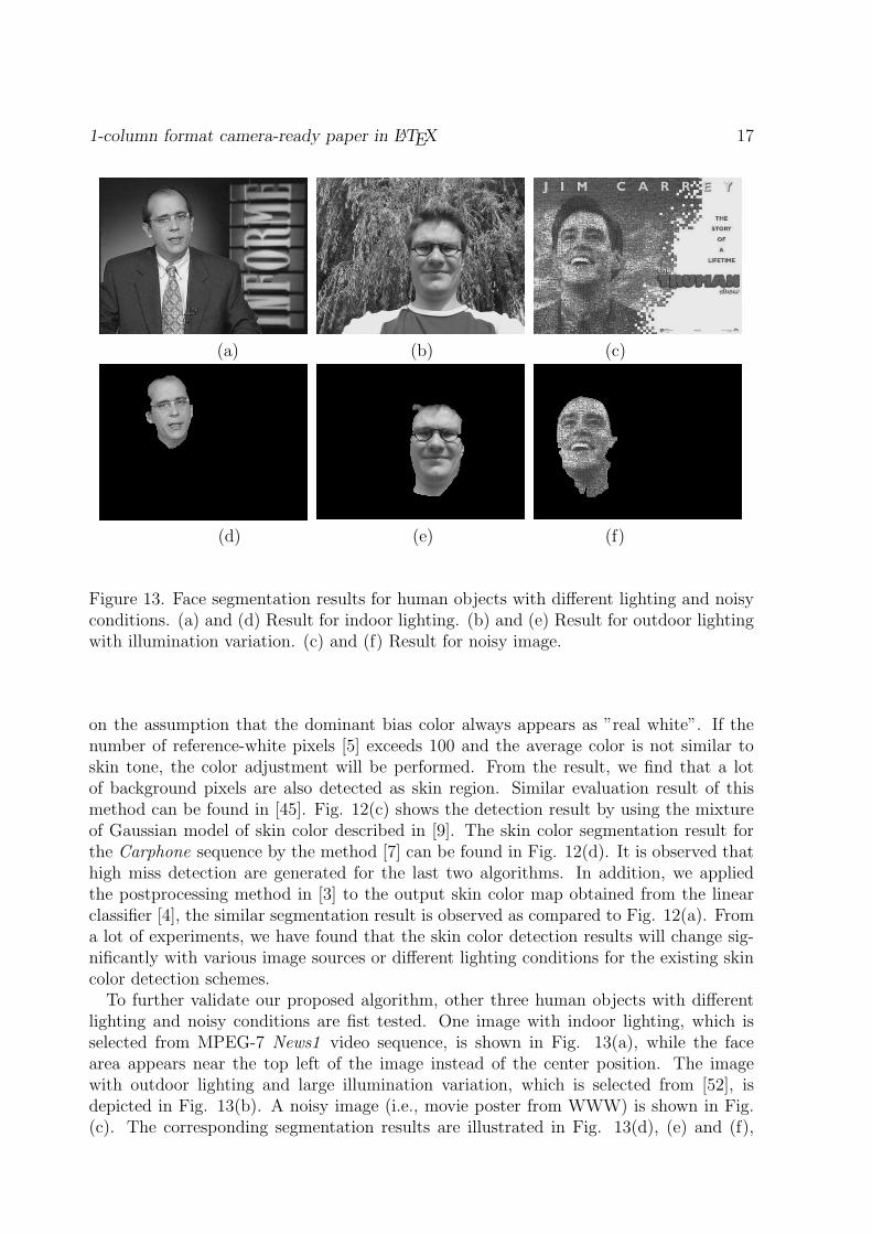
Figure 13. Face segmentation results for human objects with different lighting and noisyconditions. (a) and (d) Result for indoor lighting. (b) and (e) Result for outdoor lightingwith illumination variation. (c) and (f) Result for noisy image.
on the assumption that the dominant bias color always appears as ”real white”. If thenumber of reference-white pixels [5] exceeds 100 and the average color is not similar toskin tone, the color adjustment will be performed. From the result, we find that a lotof background pixels are also detected as skin region. Similar evaluation result of thismethod can be found in [45]. Fig. 12(c) shows the detection result by using the mixtureof Gaussian model of skin color described in [9]. The skin color segmentation result forthe Carphone sequence by the method [7] can be found in Fig. 12(d). It is observed thathigh miss detection are generated for the last two algorithms. In addition, we appliedthe postprocessing method in [3] to the output skin color map obtained from the linearclassifier [4], the similar segmentation result is observed as compared to Fig. 12(a). Froma lot of experiments, we have found that the skin color detection results will change sig-nificantly with various image sources or different lighting conditions for the existing skincolor detection schemes.
To further validate our proposed algorithm, other three human objects with differentlighting and noisy conditions are fist tested. One image with indoor lighting, which isselected from MPEG-7 News1 video sequence, is shown in Fig. 13(a), while the facearea appears near the top left of the image instead of the center position. The imagewith outdoor lighting and large illumination variation, which is selected from [52], isdepicted in Fig. 13(b). A noisy image (i.e., movie poster from WWW) is shown in Fig.(c). The corresponding segmentation results are illustrated in Fig. 13(d), (e) and (f),
18 H. Li, K. N. Ngan
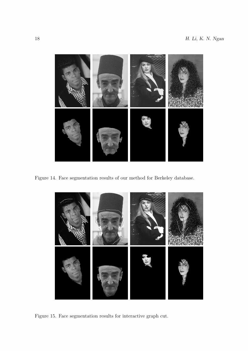
Figure 14. Face segmentation results of our method for Berkeley database.
Figure 15. Face segmentation results for interactive graph cut.

1-column format camera-ready paper in LATEX 19
respectively. It is found that the face region has been segmented very well, and most ofthe facial pixels are correctly identified with only a minimal amount of false alarms forthe boundary points. More examples are shown in Fig. 14, where the first row of imagesare selected from the widely used The Berkeley Segmentation Dataset and Benchmark[50]. The segmentation results of our method are given in the second row. From theexperimental results, we can see that better performance can be achieved by using ourproposed face segmentation method.
We also perform the comparisons of our method with the well known graph cut method[36], which is considered as a successful bilayer segmentation method. The results areshown in Fig. 15, where the first row denotes the user’s marks of the face (red lines) andthe background (blue lines). The second row is the corresponding results. We can seeour attention based automatic face segmentation performs equally well with the distinctadvantage of being unsupervised.
4.2. BSM-based Segmentation for Tracking ProcedureAfter the segmentation of the first frame, the face regions in successive frames are
obtained by the tracking based segmentation procedure. We apply our proposed algorithmto the sequence of Carphone, which is characterized by the mild-fast motion of the faceand the background in the video scene. Some original frames are shown in the first andthe third rows of Fig. 16. The final segmentation results are shown in the second andfinal rows, respectively. As opposed to the static video sequence, such as Akyio or Claire,Carphone sequence represents a scene with the deformable face contour due to the fasthead movement. It is observed that the face contour appears significant difference withthe varying postures of the human object. The segmentation result indicates that ourproposed method is capable of capturing the deformable face boundary effectively in themoving condition. Moreover, as shown in Fig. 16, the appearance of the hand in the178th frame, which also has the skin color feature, does not alter the segmentation of thetracking face region.
Another experiment of our segmentation algorithm is performed on two handset videosequences in QCIF format. Some representative frames are shown in the first and secondrows of Fig. 17. Unlike the previous sequences, such as Carphone, we use the low qualitycompressed handset videos as the input sequences, which have very low signal-to-noiseratio. The first sequence given in the first row of Fig. 17 includes the fast movement ofthe head and shoulder with the static background. In the second sequence, the movingbackground is considered as well as varying light conditions. Their corresponding seg-mentation results are given in the second and the fourth row of Fig. 17. We can see thatgood performance can be achieved using our proposed segmentation algorithm for thosevideos with noise and varying illumination conditions.
Next, we would like to analyze the behavior of the proposed tracking based segmentationalgorithm in case of errors in the object segmentation result. Firstly, the appearance ofthe false alarms in the previous segmentation is taken into account. As shown on the topleft of Fig. 18, we manually add some of background areas to the original segmentationresult. The following figures on the top row show the segmentation results obtained byusing our proposed BSM based segmentation algorithm in the tracking procedure. It isobserved that the false parts disappear gradually after several frames segmentation. The

20 H. Li, K. N. Ngan
Frame 70 Frame 80 Frame 125 Frame 160
Frame 178 Frame 290 Frame 330 Frame 380
Figure 16. Segmentation results for Carphone video sequence after face tracking. The firstand the third rows: original input frames. The second and the final rows: segmentationresults.

1-column format camera-ready paper in LATEX 21
Frame 2 Frame 10 Frame 160 Frame 218 Frame 380
Frame 3 Frame 20 Frame 81 Frame 150 Frame 179
Figure 17. Face segmentation results for two handset videos.
Frame 1 Frame 3 Frame 4 Frame 5 Frame 9
Frame 1 Frame 5 Frame 7 Frame 8 Frame 14
Figure 18. Example of robustness of the proposed BSM algorithm in case of errors inthe segmentation. Top: the appearance of false alarms. Bottom: the appearance of missalarms.

22 H. Li, K. N. Ngan
boundary points in the person’s clothing are rapidly converged to the correct boundary.From the result shown in the 9th frame, we can see that most of the false alarms arecorrected by our proposed method. Secondly, the case of miss alarms is also tested in ourexperiments. In the same way, we manually take off some facial pixels from the originalsegmentation, which is shown in the left figure at the bottom of Fig. 18. We can seethat a large part of face region is removed as the miss alarms. However, the face contouris correctly identified after the following frames segmentation. The corresponding faceboundary is again resumed to the correct status, which can be found in the result ofFrame 14. From the evaluation of this sequence, it is shown that even if the segmentationdoes not present a satisfied result for the following tracking stage, the proposed BSMbased segmentation algorithm is capable of correcting these errors effectively, and keepsthe better segmentation results.
Now, we will concentrate on the computational complexity of the proposed FSM-basedface segmentation algorithm. In our method, the facial saliency map, geometric modelverification, and eye-map detection should be taken into account in order to obtain thecorrect facial region. However, it can be seen that the computational load of the last twostages is mainly imposed on the output candidate face areas with only smaller size withrespect to the original image. Generally, in order to decrease the computational operation,we can directly skip the last two stages if only one candidate face area is detected. Inaddition, for the tracking based segmentation algorithm, i.e., BSM based segmentation,most of the computation will be consumed in the stage of motion estimation process.Only a small number of operations are required for the following BSM computation.
In addition, it should be noted that the proposed method employs the adjustable thresh-old to obtain the candidate face areas from the FSM. Generally, the smaller τ1 is, the morefalse alarms are allowed, and vice versa. By varying τ1, we can control the amount of falsealarms and false dismissals allowed in the stage of the FSM. Based on a large amount ofexperiments, a dynamic threshold τ1 (namely (0.3 ∼ 0.5)Smax), which can provide bettercandidate outputs, is reasonable for pixels classification. Some examples are illustrated inFig. 19. Here, Smax denotes the maximal value of the facial saliency map. Of course, it isdifficult to obtain the accurate face boundary only by the determination of the threshold.Nevertheless, it can be improved by using the subsequent stages of the geometric verifi-cation model and adaptive boundary correction. That is, the false face candidates canbe successfully removed by employing the following verification models. Similarly, thosefalse and miss alarms in the selected face regions can be eliminated by using the finaladaptive boundary correction.
Moreover, we also test the selection of the local window size on the segmentation per-formance. Fig. 20 shows the segmentation results of a frame for carphone video usingdifferent local windows, i.e. 4-neighborhood (diamond window), 3×3, 5×5 and 7×7. Sim-ilar results can be obtained for those small windows, such as 4-neighborhood and 3×3.
In addition, compared with Viola and Jones method, which is used to detect the hu-man face based on the AdaBoost learning method, it is observed that there are distinctdifferences between our segmentation method and Viola and Jones method. Firstly, Ourmethod concentrates on the face segmentation based on the attention model rather thanthe face location in the input image. The obtained facial saliency map not only provides

1-column format camera-ready paper in LATEX 23
Figure 19. Experimental results of akyio, carphone, and foreman videos for different τ1.The values of τ1 from left to right: 0.3, 0.45, 0.5, 0.6.
Figure 20. Experimental results of carphone video for different local windows. Left toright: 4-neighborhood, 3×3, 5×5 and 7×7.

24 H. Li, K. N. Ngan
the candidate face position, but also achieves the coarse segmentation. However, the Vi-ola and Jones method focuses on finding the face location using the detection windowat many scales. In order to extract the human face, another segmentation method hasto be employed. Secondly, Viola and Jones method is designed for the grey-level imagewithout the consideration of the skin-color information. In our work, the chrominancecomponents are the important cues in our facial saliency model. Finally, the skin colorand the gradient values are usually employed in pre-filtering the input image to speed upthe face detection for the Viola and Jones method.
5. Conclusion
In this paper, an effective face segmentation algorithm is proposed from the facialsaliency point of view. The basic idea is motivated by the observation that face areausually exhibits its special color distribution and structural feature, especially for typical”head-and-shoulder” video. Therefore, a novel facial saliency map is first constructedbased on the color, structure, and position information. Then a geometric model andfacial features are used to verify the candidate face areas. Based on the segmented result,an effective boundary saliency map is then constructed, and applied to the subsequenttracking process. Unlike other approaches, the proposed method puts heavy emphasis onthe facial saliency features for the head-and-shoulder videos. Experimental results wereobtained by applying the proposed method to a large number of video sequences. It isshown that our method is capable of segmenting the face quite effectively. In our the futurework, we hope to design more robust and efficient face segmentation algorithm in the caseof lighting variations and complex background, and make it suitable for videophone andvideo-conferencing applications.
Acknowledgment
This work was partially supported by the Shun Hing Institute of Advanced Engineeringand the Research Grants Council of the Hong Kong SAR, China (Project CUHK415505).
REFERENCES
1. T. Meier, and King N. Ngan, ”Video segmentation for content-based coding,” IEEETrans. Circuits Syst. Video Technol., vol.9, no.8, pp.1190-1203, Apr. 1999.
2. A. Cavallaro, O. Steiger, and T. Ebrahimi, ”Tracking video objects in cluttered back-ground,” IEEE Trans. Circuits Syst. Video Technol., vol.15, no.4, pp.575-584, Apr.2005.
3. D. Chai, and K. N. Ngan, ”Face segmentation using skin-color map in videophoneapplicaiton,” IEEE Trans. Circuits Syst. Video Technol., vol.9, no.4, pp.551-564, June1999.
4. C. Garcia, and G. Tziritas, ”Face detection using quantized skin color regions mergingand wavelet packet analysis,” IEEE Trans. Multimedia, vol.1, no.3, pp.264-277, Sep.1999.
5. R. L. Hsu, M. A. Mottaleb, and A. K. Jain, ”Face detection in color images,” IEEETrans. Pattern Analysis and Machine Intelligence, vol.24, no.5, pp.696-706, May 2002.

1-column format camera-ready paper in LATEX 25
6. M. Lievin, and F. Luthon, ”Nonlinear color space and spatiotemporal MRF for hierar-chical segmentation of face features in video,” IEEE Trans. Image Processing, vol.13,no.1, pp.63-71, Jan. 2004.
7. N. Habili, C. C. Lim, and A. Moini, ”Segmentation of the face and hands in signlanguage video seguences using color and motion cues,” IEEE Trans. Circuits Syst.Video Technol., vol.14, no.8, pp.1086-1097, Aug. 2004.
8. S. L. Phung, A. Bouzerdoum, and D. Chai, ”Skin segmentation using color pixelclassification: analysis and comparison,” IEEE Trans. Pattern Analysis and MachineIntelligence, vol.27, no.1, pp.148-154, Jan. 2005.
9. M. J. Jones, and J. M. Rehg, ”Statistical color model with applicaiton to skin detec-tion,” International Journal of Computer Vision, vol.46, no.1, pp.81-96, 2002.
10. H. Greespan, J. Goldberger, and I. Eshet, ”Mixture model for face color modelingand segmentation,” Pattern Recognition Letters, vol.22, pp.1525-1536, Sept. 2001.
11. B. Menser, and M. Wien, ”Segmentation and Tracking of Facial Regions in ColorImage Sequences,” SPIE Visual Comm. and Image Processing 2000, vol.4067, pp.731-740, June 2000.
12. M.-H. Yang, N. Ahuja, ”Detecting human faces in color images ,” IEEE ICIP 98,vol.1, Oct. 1998, pp.127-130.
13. J.-C. Terrillon, M. David, and S. Akamatsu,”Detection of human faces in complexscene images by use of a skin color model and of invariant Fourier-Mellin moments,” inProc. Fourteenth International Conference on Pattern Recognition, Aug. 1998, vol.2,pp.1350-1355.
14. H. Wang, and S-F. Chang, ”A highly efficient system for automatic face region de-tection in MPEG video,” IEEE Trans. Circuits Syst. Video Technol., vol.7, no.4,pp.615-628, Aug. 1997.
15. C. Chen, and S.-P. Chiang, ”Detection of human faces in colour images,” IEE Pro-ceedings: Vision, Image and Signal Processing, vol.144, no.6, pp.384-388, Dec. 1997.
16. S. Kawato, and J. Ohya, ”Automatic skin-color distribution extraction for face de-tection and tracking,” in Proc. WCCC-ICSP 2000. 5th International Conference onSignal Processing Proceedings, Aug. 2000, vol. 2, pp.1415-1418.
17. J. Park, J. Seo, D. An, and S. Chung,”Detection of human faces using skin color andeyes,” in Proc. IEEE International Conference on Multimedia and Expo, 30 July-2Aug. 2000, vol.1, pp.133-136.
18. S. L. Phung, D. Chai, and A. Bouzerdoum, ”Skin colour based face detection ,” inProc. Seventh Australian and New Zealand Intelligent Information Systems Confer-ence, Nov. 2001, pp.171-176.
19. T.S. Caetano, and D.A.C. Barone, ”A probabilistic model for the human skin color,” in Proc. 11th International Conference on Image Analysis and Processing, Sept.2001, pp.279-283.
20. J. Fritsch, S. Lang, A. Kleinehagenbrock, G.A. Fink, and G. Sagerer, ”Improvingadaptive skin color segmentation by incorporating results from face detection,” inProc. 11th IEEE International Workshop on Robot and Human Interactive Commu-nication, Sept. 2002, pp.337-343.
21. T.S. Caetano, S.D. Olabarriaga, D.A.C. Barone, ”Performance evaluation of single andmultiple-Gaussian models for skin color modeling ,” in Proc. XV Brazilian Symposium

26 H. Li, K. N. Ngan
on Computer Graphics and Image Processing, Oct. 2002, pp.275-282.22. J. Yang, Z. Fu, T. Tan, and W. Hu, ”Skin color detection using multiple cues,” in Proc.
17th International Conference on Pattern Recognition, Aug. 2004, vol.1, pp.632-635.23. R. C. Verma, C. Schmid, and K. Mikolajczyk, ”Face detection and tracking in a video
by propagating detection probabilities,” IEEE Trans. Pattern Analysis and MachineIntelligence, vol.25, no.10, pp.1215-1228, Oct. 2003.
24. C. Liu, ”A bayesian discriminating features method for face detection,” IEEE Trans.Pattern Analysis and Machine Intelligence, vol.25, no.6, pp.725-740, June 2003.
25. S. Z. Li, X. Lu, X. Hou, X. Peng, and Q. Cheng, ”Learning multiview face subspacesand facial pose estimation using independent component analysis,” IEEE Trans. Im-age Processing, vol.14, no.6, pp.705-712, June 2005.
26. A. N. Rajagopalan, R. Chellappa, and N. T. Koterba, ”Background learning for robustface recognition with PCA in the presence of clutter,” IEEE Trans. Image Processing,vol.14, no.6, pp.832-843, June 2005.
27. K. Sobottka and I. Pitas, ”A Fully Automatic Approach to Facial Feature Detectionand Tracking”, in Proc. of 1st Int. Conf. on Audio- and Video-based Biometric PersonAuthentication (AVBPA’97), pp. 77-84, Crans-Montana, Switzerland, 12-14 March,1997.
28. K.-M. Lam, and H. Yan, ”An analytic-to-holistic approach for face recognition basedon a single frontal view,” IEEE Trans. Pattern Analysis and Machine Intelligence,vol.20, no.7, pp.673-686, Jul. 1998.
29. S. Yan, X. He, Y. Hu, H. Zhang, M. Li, and Q. Cheng, ”Bayesian shape localizationfor face recognition using global and local textures,” IEEE Trans. Circuits Syst. VideoTechnol., vol.14, no.1, pp.102-113, Jan. 2004.
30. H. Luo and A. Eleftheriadis ”Model-based segmentation and tracking of head-and-shoulder video objects for real time multimedia services,” IEEE Trans. Multimedia,vol.5, no.3, pp.379-389, Sep. 2003.
31. A. Criminisi, G. Cross, A. Blake, and V. Kolmogorov, ”Bilayer segmentation of livevideo,” Proc. CVPR 2006, pp.53C60, 2006.
32. I. Levner, and H. Zhang, ”Classification-driven watershed segmentation,” IEEETrans. Image Processing, vol.16, no.5, pp.1437-1445, May 2007.
33. M. Cooper, T. Liu, and E. Rieffel, ”Video segmentation via temporal pattern classi-fication,” IEEE Trans. Multimedia, vol.9, no.3, pp.610-618, April 2007.
34. L. Grady, ”Random Walks for Image Segmentation,” IEEE Trans. Pattern Analysisand Machine Intelligence, vol.28, no.11, pp.1768-1783, Nov. 2007.
35. P. Yin, A. Criminisi, J. Winn, and I. Essa, ”Tree-based Classifiers for Bilayer VideoSegmentation,” Proc. CVPR 2007, 2007.
36. Y. Boykov, and M.-P. Jolly, ”Interactive graph cuts for optimal boundary & regionsegmentation of objects in n-d images,” In Proceedings of ICCV 2001, vol. 1, July2001, pp.105 - 112.
37. L. Itti, C. Koch, and E. Niebur, ”A model of saliency-based visual attention forrapid scene analysis,” IEEE Trans. Pattern Analysis and Machine Intelligence, vol.20,no.11, pp.1254-1259, Nov. 1998.
38. Y.-F. Ma, and H.-J. Zhang, ”A model of motion attention for video skimming ,” IEEEICIP ’02, vol. 1, 22-25 Sep. 2002 pp.:I-129-I-132.

1-column format camera-ready paper in LATEX 27
39. J. Han; K. N. Ngan, M. Li, and H.-J. Zhang, ”Towards unsupervised attention objectextraction by integrating visual attention and object growing,” IEEE ICIP ’04, vol.2, 24-27 Oct. 2004, pp. 941-944.
40. Z. Lu, W. Lin, X. Yang, E. Ong, and S. Yao, ”Modeling visual attentions modu-latory aftereffects on visual sensitivity and quality evaluation,” IEEE Trans. ImageProcessing, Vol. 14, No.11, pp. 1928-1942, Nov. 2005.
41. CVL FACE DATABASE: http://www.lrv.fri.uni-lj.si/facedb.html42. S. C. Hsia, and P. S. Tsai, ”Efficient light balancing techniques for text images in
video presentation systems,” IEEE Trans. Circuits Syst. Video Technol., vol.15, no.8,pp.1026-1031, Aug. 2005.
43. P. T. Jackway, and M. Deriche, ”Scale-space properties of the multiscale morphologicaldilation-erosion,” IEEE Trans. Pattern Analysis and Machine Intelligence, vol.18,no.1, pp.38-51, Jan. 1996.
44. J. Canny, ”A computational approach to edge detection,” IEEE Trans. Pattern Anal-ysis and Machine Intelligence, Vol. 9, No.6, pp. 679-698, Nov. 1986.
45. B. Martinkauppi, M. Soriano, and M. Pietikainen, ”Detection of skin color underchanging illumination: a comparative study,” Proceedings of the 12th IEEE Interna-tional Confernece on Image Analysis and Processing, 17-19 Sept. 2003, pp. 652-657.
46. R. C. Verma, C. Schmid, and K. Mikolajczyk, ”Face detection and tracking in a videoby propagating detection probabilities,” IEEE Trans. Pattern Analysis and MachineIntelligence, vol. 25, No.10, pp. 1215-1228 , 2003.
47. B. Froba, and C. Kublbeck, ”Face Tracking by Means of Continuous Detection,” Proc.CVPR 2004, pp. 65-71, 2004.
48. V. D., Scott, L. Yin, M. J. Ko, and T. Hung, ”Multiple-View Face Tracking ForModeling and Analysis Based On Non-Cooperative Video Imagery ,” Proc. CVPR2007, 2007.
49. Y. Li, H. Ai, Y. Takayoshi, S. Lao,and K. Masato, ”Tracking in Low Frame Rate Video:A Cascade Particle Filter with Discriminative Observers of Different Lifespans,” Proc.CVPR 2007, pp. 1-8 , 2007.
50. D. Martin and C. Fowlkes and D. Tal and J. Malik, ”A Database of Human Seg-mented Natural Images and its Application to Evaluating Segmentation Algorithmsand Measuring Ecological Statistics,” in Proc. 8th Int’l Conf. Computer Vision, vol.2, July, 2001, pp. 416-423.
51. P. Viola and M. J. Jones, ”Robust real-time face detection,” International Journal ofComputer Vision, Vol. 57, No. 2, pp. 137-154, 2004.
52. C. Rother, V. Kolmogorov, and A. Blake, ”GrabCut: interactive foreground extractionusing iterated graph cuts,” In Proceedings of SIGGRAPH 2004, 2004.