safety united states air force • august 1970
TRANSCRIPT

SAFETY UNITED STATES AIR FORCE • AUGUST 1970

COVER ART-COurtesy of Vought Aeronautics, LTV Aerosp1ce Corp., Dallas, Te111.
LT GEN S. W. WELLS Inspector Genera I, USAF
MAJ GEN EDWARD M. NICHOLS, JR. Deputy Inspector General for Inspection and Safely, USAF
BRIG GEN B. H. KING Director of Aerospace Safety
COL BRITT S. MAY Director of Nuclear Safety
COL WILLIAM J. MURPHY, JR. Chief, Flight Safety Division
COL STEPHEN WYSOCKI Chief, Ground Safety Division
COL RICHARD F. JONES Chief, Missile and Space
Safety Division
COL FERDINAND BARNUM Chief, Life Sciences Group
MR RICHARD F. GERWIG Chief, Reporting and Documents Group
COL HOWARD S. DAVIS Chief, Systems Safety
Engineering Group
COL JAMES A. TALBOT Chief, Safety Education Group
MAJOR CYRIL W. MINETT Editor
ROBERT W. HARRISON Managing Editor
CMSGT LLOYD E. THOMPSON Technical Ed itor
M. WAGNER Staff Writer
FRANKLIN E. MORSE Art Ed itor
MSGT HERBERT H. NIXON Assistant Art Editor
SGT JAMES W. DOUTY Staff Illustrator
TSGT DAVID L. REIS Staff Photographer
UNITED STATES AIR FORCE • AUGUST 1970
FOR AIRCREWS, MAINTENANCE & SUPPORT TECHNICIANS
SPECIAL FEATURES e UEls AND YOU •.• are you ready for a "no-no"? ................... ......... ... ... 1
GUIDE TO DRUG ABUSE ... don't be a pill popper --- --- ---- -- -------- ---- ------- --- 6
PLANE TALK ... voice communication ------ --- ------------- --- ------- --- ------ ---- --- 8 WAKE TURBULENCE ... tests and results -- --- ---- --- ---- --- ----- -- -------- -- ----------- - 10 A NEW BREED OF CAT ..• flexible bellows in aircraft --- -------------- ----- --- --- -- 14 SELF-LOCKING NUTS ... types and uses ------------ ------ --- ----- ------------ -- --- -- -- - 16 RESPONSIBILITY ... true experience from a supervisor ----------- -- -- ----- ---- 18
A-7D .•. all about the Corsair II ---------------------------------- --- ---- ------------ --- 20 flASHBACK ... checklists can save a life ----- -- --- ------ ---- -- ---------------------- 28
REGULAR FEATURES IPIS APPROACH _ .. __ .. . . . . . . 5 TOOTS . .. .. .. .. . .. .. . .. . .. . 9 REX RILEY'S X-C NOTES __ . __ 17 LOST AND DOWNED _ .. _ .. _ .. 19 OPS TOPICS .. __ . . .. _ . _ ... _ 25
DEPARTMENT OF THE AIR FORCE •
NUCLEAR SAFETY AID STATION . 30 TECH TOPICS .... __ .. . .. .. .. 34 EXPLOSIVES SAFETY ... .. . _ . . 38 MAIL CALL .... .... _ ........ 40 WELL DONE . .. .. .. .. • .. .. .. 41
THE INSPECTOR GENERAL, USAF
SUBSCRIPTION-AEROSPACE SAFETY is available on subscription for $3.50 per year domestic; $4.50 foreign; 30c per copy, through the Superintendent of Documents, Government Printing Office, Washington, D.C. 20402. Changes in subscription mailings should be sent to the above address. No back copies of the magazine can be furnished. Use of funds for printing this publication has been approved by Headquarters. United States Air Force, Department of Defense, Washington, D.C. Facts, testimony and conclusions of aircraft accidents printed herein may not be construed as incriminating under Article 31 of the Uniform Code of Mil itary Justice. All names used in accident stories are fictit ious. No payment can be made for manuscripts submitted for publication in the Aerospace Safety Magazine. Contributions are welcome as are comments and criticism. Address all correspondence to the Editor, Aerospace Safety Magazine, Deputy Inspector General for lnspectron and Safety, USAF, Norton Air Force Base, Californra 92409. The Editor reserves the right to make any editorial change in manuscripts which he believes will improve the material without altering the intended mean ing. Air Force organizations may reprint articles from AEROSPACE SAFETY without further authorization. Prior to reprrnting by non-Air Force organizations, it is requested that the Editor be queried, advising the intended use of material . Such action will insure complete accuracy of material, amended in light of most recent developments. The contents of this magazine are informat ive and should not be construed as regulat ions, techn ical orders or di rectives unless so stated.
AUGUST 1970 AFRP 127-2 VOLUME 26 NUMBER 8
•
•
•

•
•
•
•
•
Lt Col David A. Crossman, Directorate of Aerospace Safety
son Early one morning, as you pass
Base Ops on your way to work, you notice a transient C-11 8
parked and a couple of people deplaning. Another glance at the group stirs your curiosity about who·s arriving, for amidst the reception party greeting a General Officer you note the Wing Commander, the DO, the DM and your boss. the Chief of Maintenance. Continuing on to your duty section you try to remember who was scheduled in today. Nothing was said at the staff meeting Friday morning. . . . Suddenly a sinking feeling comes over you: ''Oh, no, they can ' t be the JG oNotice team. "
As you herd your car into the parking lot a multitude of items are running through your mind-things that should have been seen to before they hit us. What was it the boss said last month? "Get out our latest inspection and safety survey reports and insure we have complied with the sta ted corrective actions. Also, run that self-survey checklist through each of your activities. We
have got to get ready for this nonotice program the JG has come up with."
The scene is set for what could happen to you some morning. For some of you the experience is history. The Unit Effectiveness Inspection (UEI) program conducted by the USAF Inspector General (TIG) has been in operation since late July 1969. The program was implemented by Chief of Staff direction and is designed to apprise him and subordinate commanders of the operational capability of Air Force units world-wide. During FY 70 UEI teams have traveled on 52 efforts, visited 8 1 locations, and inspected 9 1 units, within 13 major air commands.
The implication in the staged setting is that the individual 's area of responsibility is not ready for inspection or at least he has a feel ing of uncertainty. The age old procedure of preparing your shop for a pre-announced inspection has been preempted by the UEI program. No longer do you have the advantage of
AUGUST 1970 • PAGE ONE

A member of the UEI team will be in
"clean up and look sharp while the IG is here." What frequently happened to units under the pre-announced inspection program was that management actions taken to eliminate or correct deficiencies were short term measures which unexplainably vanished after the inspection team departed. This situation is ineffective and does not truly reflect the daily routine posture of the unit being inspected. The nonotice concept places the emphasis on the quality of management as it really is.
Analysis of UEI reports indicates that a number of findings in the maintenance area are common to the majority of units visited and very possibly exist in your unit. Those of you already visited will probably call foul but it's time to air these common maintenance deficiences in the interest of better aircraft maintenance which will result in safer aircraft and an increased operational capability. The topics which follow are not all-inclusive of common maintenance deficiencies noted during FY 70 UEis; but they do represent deficiencies that sig-
nificantly degraded the quality of maintenance and jeopardized the USAF Aircraft Accident Prevention Program.
TECHNICAL DATA
One of the first items of business for some of the maintenance UEI team members is a walk-through of the maintenance work areas, flight line and most shops. Invariably their note pads start to fill up with namesdates-and places of maintenance being performed without technical data at hand. This violation of a basic maintenance principle is frequently found throughout the maintenance complex starting at the flight line and continuing through all shops. Typical specific acts noted include:
• Preflight/ postflight inspections being accomplished without use of work cards.
• Periodic/ phase inspections being accomplished without use of work cards.
• Engine runups in progress without use of checklists.
• Engines being built-up without reference to TOs.
• Avionics repair actions being
PAGE TWO • AEROSPACE SAFETY
accomplished on aircraft and inshop without use of TOs.
• Aircraft servicing operations being conducted without use of checklists.
• Tightening of fittings that require specific torque values without the use of a torque wrench or reference to TOs.
If these findings read like a broken record sounds, you need only to read one accident report where failure to use tech data resulted in the loss of a valuable aircraft and human life. Then the WHY of the continual cry of use that tech data comes through loud and clear.
A point of interest to the inspectors is how quickly the word gets around the maintenance complex. By that afternoon or the next day, the TOs and checklists are being used.
QUALITY CONTROL/ ASSURANCE
When the maintenance watchdog goes to sleep, or if his barking goes unheard, the bird killer-maintenance malpractice-will create utter chaos in your hen house. The type
•
•
•

-, • 7..:.,.._
our area within minutes after arriving on base-be ready for him
•
•
•
and number of deficiencies noted in the QC/ QA sections of the various units inspected suggests that management's primary tool for sampling the quality and reliability of the maintenance effort, Quality Control, is in many instances ineffective and in some cases apparently ignored by management. Review of QC/ QA activities revealed these common deficiencies:
• Work cards and checklists overdue 90-day validation.
• A low failure rate of job evaluations noted in units under the Maintenance Standardization Evaluation Program (MSEP).
• In-progress inspection program ineffective and not monitored by QC.
• 180-day activity inspection not thorough and searching.
• Excessive time taken to route inspection reports through appropriate supervisors.
• Corrective action answers to inspection reports poor and permanent corrective action not being taken.
• Lack of follow-up. by QC to insure stated corrective action was complied with .
• Unsatisfactory inspection reports not forwarded ·to top level management for review.
An effective Quality Control program is a two-way street maintained in balance by management's attitude, influence and emphasis. The inspections must be thorough, searching, and frequent enough to insure a representative sample of the routine maintenance effort. The criticisms reported by the inspection must be reviewed in proper perspective so that corrective actions taken are meaningful and lasting.
Actually, the maintenance findings of a UEI are a direct reflection on the effectiveness of the unit's QC program . Determination of where the weakness lies-management emphasis, QC itself, or apathy within maintenance sections is readily apparent by reviewing inspection reports and corrective action.
MAINTENANCE ANALYSIS
The use of deficiency analysis in the role of "trouble-shooter" for management is ineffective and in some instances non-existent. The lack of an active analysis program is denying managers, supervisors
and technicians valuable and needed assistance. The raw data is available in ab und ant quantity-incidents, UMRs, inspection reports, high failure rates, etc., but very little meaningful analysis is performed. Examples of UEI findings which support this contention are as follows:
• High failure rate items identified but no attempt made to determine failure cause factors.
• Maintenance malpractices identified in Quality Control inspections but no attempt to determine personnel responsible in order to conduct retraining.
• Ineffective in-process inspection item listings due to a lack of comprehensive review and coordination with Quality Control and work centers.
To condemn an individual for a malpractice or an aircraft system for a malfunction is easy. More times than not all that transpires is criticism of the man or the equipment. What is really needed is to determine why the man did what he did or why the system failed. When you have the whys then you're well on your way to preventing the act from recurring. To determine the whys
AUGUST 1970 • PAGE THREE
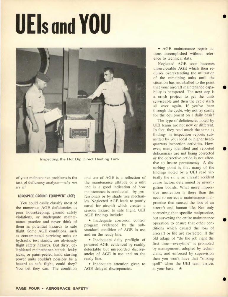
UElsondYOU
Inspecting the Hot Dip Direct Heating Tank
of your maintenance problems is the task of deficiency analysis-why not try it?
AEROSPACE GROUND EQUIPMENT (AGE)
You could easi ly classify most of the numerous AGE deficiencies as poor housekeeping, ground safety violations, or inadequate maintenance practice and never think of them as potential hazards to safe flight. Some AGE conditions, such as contaminated servicing units or hydraulic test stands, are obviously flight safety hazards. But dirty, delapidated maintenance stands, leaky jacks, or paint-peeled hand starting power units couldn't possibly be a hazard to safe flight, could they? You bet they can. The condition
and use of AGE is a reflection of the maintenance attitude of a unit and is a good indication of how maintenance is conducted-by professiona ls or by shade tree mechanics. Neglected AGE leads to poorly cared for aircraft which creates a serious hazard to safe flight. UEI AGE findings include:
• Inadequate corrosion control program evidenced by the substandard condition of AGE in use and on the ready line.
• Inadequate daily preflight of powered AGE, evidenced by readily detectable but unrecorded discrepancies of AGE in use and on the ready line.
• Inadequate attention given to AGE delayed discrepancies.
PAGE FOUR • AEROSPACE SAFETY
• AGE maintenance repair actions accomplished without reference to technical data.
Neglected AGE soon becomes unserviceable AGE which then requires overextending the utilization of the remaining units until the situation has snowballed to the point
•
that your aircraft maintenance capa- e bility is hampered. The next step is a crash project to get the units serviceable and then the cycle starts all over again. If you've been through the cycle, why not try caring for the equipment on a daily basis?
The type of deficiencies noted by UEI teams are not new or different. In fact, they read much the same as findings in inspection reports sub-mitted by your local or higher headquarters inspection activities. However, many identified and reported deficiencies are not being corrected or the corrective action is not effec-tive to insure permanency. A disturbing point is that many of the findings noted by a UEI read vir-tually the same as aircraft accident cause factors determined by investi-gation boards. What more impres-sive motivation is there than the need to correct a maintenance malpractice that caused the loss of an aircraft and human life. Not only correcting that specific malpractice, but surveying the entire maintenance operation to ensure that other conditions which caused the loss of aircraft or life are corrected. If the old adage of "do the job right the first time-everytime" is promoted by management, adopted by technicians, and enforced by supervision then you won't have that "sinking spell" when the UEI team arrives
at your base. *
•
•
•

•
•
•
•
•
---···-----
THE 1.ets. By the USAF Instrument Pilot Instructor ......ttl.
School, (A TC) Randolph AFB, Texas
CIRCLING APPROACH
A note in the IFR Supplement states, "The circling MDA and weather minima to be used are those for the runway to which the final approach is flown-not the landing runway." The reason you use the minimums for the runway to which the final approach is flown is to assure that required obstacle clearance is provided in both the final approach and circling approach areas. Despite this note, there is still confusion on this point, and some pilots are still using minimums for the runway to which they are circling.
HIGH ALTITUDE TEARDROP PENETRATIONS
We have had several questions and comments on our October 1969 "IPJS Approach" article concerning teardrop penetrations. Specifically, how do you "remain within, etc." specified on some VOR and ADF high altitude approaches. ln order for you as a pilot to be required to remain within a certain distance on a teardrop VOR or ADF penetration you should be provided a fix (DME, crossing radials or radar); otherwise, there is no precise method of determining your range from a VOR or ADF. If a VOR or ADF teardrop penetration approach is constructed according to
JAFM 55-9 the obstacle clearance limit criteria are based on the amount of altitude to be lost and course divergence in the teardrop penetration. Do not confuse with procedure turn depictions!
MISSED APPROACH CLIMB GRADIENT
Whenever a missed approach procedure requires a climb gradient greater than 150' / mile, a note is added on the approach plate and the required climb gradient in feet/mile is published. For example, Norton AFB (SW High Altitude Terminal) missed approaches require climb gradients greater than 150' / mile. How · do you as a pilot, convert feet/mile climb to a vertical velocity rate? A simple technique used at the IPIS is to multiply your groundspeed in nautical miles per minute
-------~-----·-
times the required climb gradient. For example, the Norton ILS 4 RWY 5 missed approach requires 325'/ NM climb gradient. If your missed approach climb airspeed is I 80KTS (3NM/ MIN) the vertical velocity rate needed to achieve 325' / NM is 975'/ MIN, (325 x 3) . For you jocks using MACH indicators, remember that indicated MACH times 10 is approximately true airspeed in nautical miles/minute. (Example-.3 MACH x 10 = 3NM/MIN.) Some pilots may feel that it's "No Sweat" to maintain a rate of climb sufficicm to ensure missed approach climb requirements; but apply this technique to a loss of power situation. Can you maintain the required climb gradient at engineout climb airspeed?
POINT TO PONDER
AFM 51-37 allows you to start descent from procedure turn altitude, with outbound course guidance, when the aircraft is headed inbound and positioned within 20 degrees of the inbound course. The revised AFM 51-3 7 will allow descent from the procedure turn
altitude, with outbound course guidance, when the aircraft is positioned within I 0 degrees of the procedure turn course and is on an inbound imercept heading. Rationale for this change is that, a pilot descending to the FAF altitude 20 degrees off the inbound course and l 5NM out (Category E) may not have sufficient obstacle clearance.
The final draft of the revised AFM 51-37 has been forwarded for editing and printing, hopefully it wiU be on your desk soon.
IRC MAILING LIST The !PIS requests those agencies conducting Annual
fnstrument Refresher courses to forward their current mailing aduresses. These will be used to correct the IPIS mailing list and will insure that your IRC receives up-to-date materials for instrument training. Send addresses to USAF IPIS (AT), Randolph AFB
TX 78148. *
PAGE SIX • AEROSPACE SAFETY
•
•
• Maj Paul T. Hansen, USAF, MC, Hq ATC
MODERN CHEMISTRY has produced an al· most infinite variety of drugs for the benefit e of man. Unfortunately, the qualities that make these drugs effective and desirable also promote abuse with undesirable-even dangerous-consequences. Abuse is not lim· ited to the furtive pill popper, acid head or mainliner, but is exhibited by vast numbers of "straight people" who overdose, borrow or self-prescribe prescription or over-the· counter remedies. Drug abuse and flying are not compatible, as the author points out in the following article. Although written for aircrews-primarily pilots-the article ap· plies to maintenance personnel, air traffic e
•
•
•
•
•
controllers and any others whose work may affect the successful performance of the flying mission.
0 ur society has become drug oriented, and no longer can we hide behind the old stereotyped, arti
ficial line drawn between narcotic drugs and non-narcotic drugs, bad drugs and good drugs, illegal drugs and legal drugs, dangerous drugs and safe drugs. A drug is any chemical that produces an effect when taken into the body. The resultant effect may be beneficial, harmful, or both, depending upon what is taken, who takes it, how much he takes, and why he takes it. Aspirin is a drug. Opium is a drug. Penicillin and coffee are drugs. Marihuana, LSD and nicotine are all drugs.
No longer can we concern ourselves only with the classical distinction between use, habituation, dependence and addiction. Any usable drug can and probably has been abused by someone. Abuse occurs when a drug is inappropriately, unwisely, intemperately or illegally used. Most of us are aware that alcohol can be both used and abused. In a similar way aspirin and penicillin can be both used and abused. For some drugs such as opium or heroin, the mere use obviously constitutes abuse.
THE REAL FINK Common sense dictates that flyers
should not abuse drugs, yet the same personality traits that lead to drug abuse also lead to irresponsible behavior. Thus, flight safety and mission effectiveness behoove all student pilots, pilots and instructor
pilots to observe their fellow aviators for any indication of possible drug abuse. Of course, drug abusers consider this "finking," but the real fink is someone who would knowingly allow a drug abuser to risk lives and airplanes by flying.
Most of us would recognize a drug abuser who sat with his flying suit sleeve rolled up and "mainlined" some drug during a premission briefing. Unfortunately, the secretiveness of most drug abusers and the subtleness of some drug effects make detection by both the trained and casual observer very difficult. In addition, the frightening possibility exists that someone who is now straight, yet used acid or STP in the past, may appear completely normal. He may even think all is normal. The danger lies in the possibility of a "flashback" occurring. A flashback is a "free trip." Someone who has taken LSD or STP in the past can at any time, suddenly, spontaneously, and unpredictably start on another trip. Obviously such a happening could result in his death, your death or someone else's.
The user of the so-called hard drugs, e.g., heroin, opium and mainlined speed, is not hard to recognize. The self-destructive personalities necessary to use these drugs are not usually conducive to achieving the level of performance necessary to be a USAF pilot. Thus, the easier a drug abuser is to spot the less likely he is to be a fellow flyer.
We all know that the alcoholic can vary from the skid row derelict to the completely normal appearing gentleman. Likewise, drug abusers vary in appearance from obviously antisocial appearing characters to neatly dressed, crew-cut aviators. Most signs of drug abuse in a pilot are subtle and nonspecific; very few are definitive. Look for two main clues to increase your level of suspicion:
Intoxication-Intoxication by most drugs is similar to the intellect and performance decrements mani-
fested by alcohol intoxication. Some signs of intoxication-all drugs:
• Judgment impairment • Overconfidence • Decrease in coordination • Difficulty with speech, e.g.,
slurring • Pinpoint pupils in subdued
light • Dilated pupils in brightly lit
areas • Euphoria • Depression • Excessive sweating • Tremor Inappropriate changes (particu
larly if occurring over a one to two week period of time )-best seen by close friends and associates:
• Changes in behavior • Marked changes in personality • Sudden changing of friends and
associates • Inappropriate secretiveness of
actions
• Inappropriate mood • Irresponsible behavior • Sudden changes in manual
dexterity • Sudden changes in academic
performance The more one looks for the subtle
signs the more likely he is to detect them.
It should be stated that each of us may manifest one or more of these signs and symptoms at one time or another and not be a drug user or abuser. In fact, the fledgling pilot frequently displays combinations of enthusiasm and anxiety that might resemble drug effects, e.g., bumping into doors, stumbling over chocks, slurring of speech, excessive sweating, inattentiveness, etc. In most of these instances all the student needs is direction, sympathy and understanding; but we must watch out that the drug abuser doesn't hide behind the mask of a bumbling student.
"Keep alert, watch for THE OTHER TRAFFIC." * AUGUST 1970 • PAGE SEVEN

PLANE TALK Lt Col Scotty O. Ferguson, Directorate of Aerospace Safety
From the sound of things in the air these days, aircrews are having difficulty with one of the
basics of aviation: voice communications. Here is where air discipline has been sorely neglected .
The written guidance on air to ground communications is not consolidated in one document for quick and easy reference, and perhaps this should be done. However, the do's and don'ts of airborne radio transmissions are available in publications such as FLIP Planning, FLIP Enroute and Airman's Information Manual. This guidance used with a modicum of common sense and professional pride would make our
radio frequencies a lot less cluttered. This in turn would eliminate a great deal of the confusion in high density air traffic areas.
AFM 51-37 (Instrument Flying), Chapter 15, under voice procedures says, "During an approach, repeat all headings, altitudes and altimeter settings ; acknowledge all other instructions unless otherwise advised. During high density radar operations, a limiting factor is the communications time available. Keep transmissions brief and specific, commensurate with safety of flight."
The accepted method of acknowledging transmissions is with either ROGER or WILCO preceded by
PAGE EIGHT • AEROSPACE SAFETY
the aircraft or tactical call sign. No other words are necessary or called for.
The enroute portion of flight is probably where radio discipline gets the most abuse. FLIP Planning tells us to advise center when we are vacating a previously assigned altitude, but it does not require us to announce our arrival at an altitude. When we are given a new frequency all that is required or desired is an acknowledgement, not a repeat of the new frequency. When we check in with an enroute center controller, we are required only to state the assigned cruising altitude; and, if climbing or descending, the altitude passing.
Unless otherwise requested, enroute clearances require only an acknowledgement, not a repeat of that clearance. And, incidentally, when being passed from one controller to another, "Thank you, sir, and good day," may make the controller feel warm all over, but it irritates fellow aviators on the same frequency. When flying in a non-radar environment, more words are necessary but following prescribed procedures will minimize transmission time.
The skies are getting more crowded every day and consequently, strict air discipline becomes increasingly important. There are definite procedures to follow in the operation of all aircraft systems. The radio is one of those systems. Know and use the correct procedures. *
•
•
•
•
•

•
•
•
•
•
is interested in your problems. She spends her time researching questions about Tech Orders and directives. Write her cl o Editor (IGDSEA), Dep IG for lnsp & Safety, Norton AFB CA 92409
Dear Toots Please help settle a difference of opinion concerning
the aircrew check of the longitudinal flight control check on the RF-4C before taxiing. The difference centers around TO 1F-4(R)C-l, page 2-25, para 5; TO 1F-4C-2-4, para 3-29 (for example), plus an article "F-4 Flight Control System-Faults and Fixes" authored by Maj Jerry Gentry, USAF Flight Test Center, Edwards AFB, which has appeared in the Feb 1970 TAC Attack and May 1970 AIRSCOOP. It is my opinion that the references are correct, as listed above. It is the opinion of my operations officer and a tech rep from McDonnell-Douglas that all those references are not enough to require the stick to remain aft on the flight control check.
My question: After TO 1 F-4-831, with two units nose down trim, what is the stick supposed to do when I pull it to the aft stop, hold it momentarily and then release it? And what are the limitations, if any?
If the stick is allowed to (or may) fall forward to the stop at any rate which happens to be there, what are the chances of getting the applicable tech orders changed. And, if the stick is not allowed to fall to the forward stop, please tell me why and how I should enter this in the 781 as a discrepancy when the stick does fall forward.
Maj Bernard F. Albers APO San Francisco 96237
Dear Major A
The answers to your questions were provided by John Krings, experimental test pilot at McDonnell Aircraft Company. Perhaps others have the same questions so I am using his reply in full.
"! think the most important part of any check done to an airplane is to know what you are checking and generally what to expect. The actual technique and tolerances are often arbitrarily defined to standardize procedures or allow for normal variation in operators or systems.
The check under discussion is merely to check the freedom of movement of the longitudinal control system. Phrases like "free and easy," "a wet noodle," and "locked in concrete" mean various things to different people. So-we found in old 5 lb. bobweight F-4s that with TO trim the bobweight effect should overcome any allowable friction in the longitudinal control system. We now had a "built-in fish scale"-pull the pole back, lift the bobweights and let go to see if the bobweight can overcome the friction and pull the pole to the forward stop. The problem that developed later was the rigid interpretation of the check when it was a convenient guide to check the friction level.
When we incorporated the 3 lb. bobweight, obviously the system changed. If the allowable friction needed 5 lb. bobweights to overcome it, it stands to reason a 3 lb. weight may not be enough. It wasn't. Now with a 3 lb. bobweight the maximum allowable friction may exceed the effect of the bobweight. It is as simple as that.
We do not check for minimum friction . Friction in longitudinal systems is obviously undesirable. Therefore, any time the control stick goes forward, the farther and faster the better. If a 3 lb. bobweight will move the stick all the way to the forward stop, we have a good low friction system.
Remember the check is merely putting a known force (the bobweight) against an unknown force (the friction) and using the stick position/ movement to measure the winner!
We flew thousands of airplanes in the past without making rigid inflexible, misunderstood, control checks with amazing results. A Litle discretion is all that is required. Don't forget there is no "no brain" check for lateral and directional friction.
With a 3 lb. bobweight it may or may not go forward, just move it back and forward and insure the friction is not too high."
AUGUST 1970 • PAGE NINE

Wake Turbulence
VORTEX WAKE TURBULENCE has been a subject of interest for many years with the theory
dating back to the beginning of powered flight. Hazards to following airplanes resulting from wake turbulence were recognized and published for light airplane operators as early as 1952. Development of large jet transports led to speculation that turbulent wakes generated by these airplanes would present a significant hazard to other air traffic and that special separation standards might be required for large jet transports. The Boeing Company began the study of wake turbulence in 1963. The study was continued to examine the effect of wake turbulence on following airplanes in mid-1969. This study was recently completed with a series of flight test evaluations conducted by Boeing in cooperation with NASA and the FAA.
Wake turbulence should not be confused with "jet wake" (sometimes called "jet blast" or "thrust turbulence"). Jet wake is created by high-velocity air expelled from the fan and turbine of a turbojet engine. Jet wake is of concern only when the airplane is taxiing or parked with engines running. Jet wake has no significant effect on wake turbulence.
Wake turbulence or vortex turbu-
Reprinted from Boeing Airliner
lence, on the other hand, is generated during flight when the wing is developing lift. Figure I shows the vortices are two counter-rotating air masses, the right wing vortex rotating counterclockwise, and the left wing vortex rotating clockwise. The region of rotating air behind the airplane comprised of the trailing vortices is the turbulent wake.
WAKE TURBULENCE TESTING
Analytical studies of wake turbulence and its effect on following airplanes began at Boeing in July 1969 and culminated in a series of flight tests conducted in December 1969 and February of this year. In December, an evaluation of the 747's
PAGE TEN • AEROSPA CE SAFETY
turbulent wake was conducted by flying behind the airplane with the Boeing-owned F-86. These tests indicated that the 747 wake did not present a hazard to following airplanes at the standard three mile separation. However, the F-86 pilot was unable to see the wake and therefore could not be assured that he had thoroughly sampled it. In subsequent tests, Boeing installed smoke generating equipment on the outboard engines of a 747 and a 707-320B. Smoke generated by this system in flight becomes "wrapped up" in the trailing vortices making them visible to chase airplane pilots. In February, Boeing conducted a series of tests in cooperation with NASA and FAA. These tests were
TRAILING VORTEX
TURBULENT WAKE
FIG. 1-Two counter rotating air masses form tra il ing vortices behind the airplane.
•
•
•
•
•

•
•
•
•
•
u w FOLL<JflNG
1AIRPLANE WING SPAN
80
~ C) w 0
3 MILE SEPARATION I
r--37 FT w .... < L -
60
°' I .. il[T""" _J _J
0
°' 93 FT 40
u 00 w ~ 0 w 80 0
w f-<
60 a:: _J _J
0 1 a:: '
LANDING PPROACH
.. .. l-a: Ill a: Ill z 0 I- "' D.
0 UI
v J
0 40 w x .J ..
--------------........- !!-D. - ~ u ::> 0 ~
r >-118 FT
& . 20
u :J 0 ~
IL a: I-
¥ ~ , ,..
~ 20 :..::
I
t--~---+---t----f" ..... rT"+---r--~ < - - - < UI L
w a..
0 0 I 00 200 300 400 500 600 20 40 60 80 I 00 120 140
WAKE GENERATING AIRPLANE GROSS WEIGHT-1000 LB. WING SPAN FT
FIG. 2-Test data showing the roll experienced by airplane of a given wing span flying in wake of different weight airplanes .
FIG. 3-Test data showing the roll experienced by airplanes of different wing span flying in wake of a 400,000 lb. airplane.
designed to provide a direct comparison between the 747 and an airplane representative of the current jet fleet, the 707-320B. The following tests were conducted:
• Boeing flew a 737-100 airplane in the wakes of a 747 and a 707-320B airplane at separations of 3 to 9 nautical miles. The 747 and 707 airplanes were airborne simultaneously and were flown in comparable cruise and approach configurations.
• NASA flew its Convair 990 airplane in the wakes of 7 4 7 and 707 airplanes. Again, the 747 and 707 were airborne simultaneously and were flown in comparable configurations.
• Boeing flew several passes with a 747 and a 707-320B in an FAAconducted test over an instrumented tower at altitudes of 300 feet. The tower was instrumented to record vortex velocities and photograph vortex smoke trails.
• Boeing flew a 737-100 series
FIG. 4--<Above) Trailing vortices level off below the flight path and are never encountered more than 900 feet below the aircraft.
FIG. HRight) The turbulent wake drops be·
airplane in landings behind a 747. The 737 followed the 747 by 1.8 to 3.0 nautical miles and was intentionally flown below the 747's glide slope to encounter and evaluate the effect of wake turbulence on landing.
Also during this same period, the FAA and NASA conducted tests with the CV-990 flying behind a C-5A, and tower fly-bys with a C-5A and other jet transport airplanes.
TEST RESULTS The most significant result ob
tained from the tests was that the following aircraft (737 and NASA CV-990) could not detect any difference in the wakes generated by 747, C-5A, and 707-320B airplanes. Data from these tests and earlier NASA tests are shown in Figures 2 and 3. Figure 2 shows that the roll rate experienced by a following aircraft is approximately the same in the wake of a 200,000
lb airplane as it is behind a 600,000 lb airplane. Figure 3 shows that the wing span of the following airplane has an important effect on the roll experienced in the wake of a jet transport.
Another significant result obtained from the test was that the wake levels off below the generating aircraft. It was found that the wake moves down behind the generating aircraft at approximately 500 feet per minute as expected, but then levels off at approximately 700 feet below the airplane as shown in Figure 4. The wake was never found to be more than 900 feet below the flight path.
In the landing tests, a 73 7 made safe landings as close as 1.8 nautical miles behind the 747. It was found, however, that a combination of factors could lead to an undesirable wake turbulence encounter at such close spacings. These factors were a light (1 to 5 knot) crosswind com-
FLIGHT PATH
WAKE TURBULENCE
,,,,... ,- ,- ---.----T---.-- -.,---
)' (; T= 0 SECONDS
1----+---+----t-11--~:100 I
0 CROSSWIND
T 1-5 KNOT CROSSWIND
6-10 KNOT CROSSWIND
200 100
!= T: 20 SECONDS g 1f =10 SECONDS
~ GR~D PLA~E FT
e;, T = 10 I SECONDS
T= 20 SECONDS
1
6 KNOT CROSSWIND
/ Tl= 0 SECONDS ...__
T= 10 sec&iDs T = 20 : SECONDS I
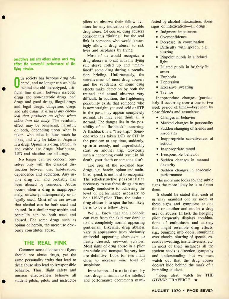
FIG. 6--Typical effect of crosswind on the movement of vortices near the ground.
bined with flying the following aircraft below the approach path of the preceding aircraft. No significant turbulence was encountered when landing the 737 approximately 2.5 nautical miles behind the 747.
The tests also revealed that within approximately Yz wing span (50-100 feet for the 747) of the ground,
the strength and movement of the vortices are strongly affected by the presence of the ground (ground effect). It was observed that when the generating aircraft is in ground effect, the wake does not form into concentrated vortices and turbulence in the wake is relatively weak. Thus as shown in Figure 5, there is no
strong turbulence in the touchdown area. On approach and takeoff, the wake descends below the flight path until it enters ground effect whereupon the two vortices stop their downward descent and move laterally. This behavior is illustrated in Figure 6. With no crosswind, two vortices in ground effect move apart to clear the flight path. Crosswinds of 1 to 5 knots cause one vortex to remain near the flight path while winds greater than 5 knots cause the vortices to move quickly across the flight path and to break up rapidly.
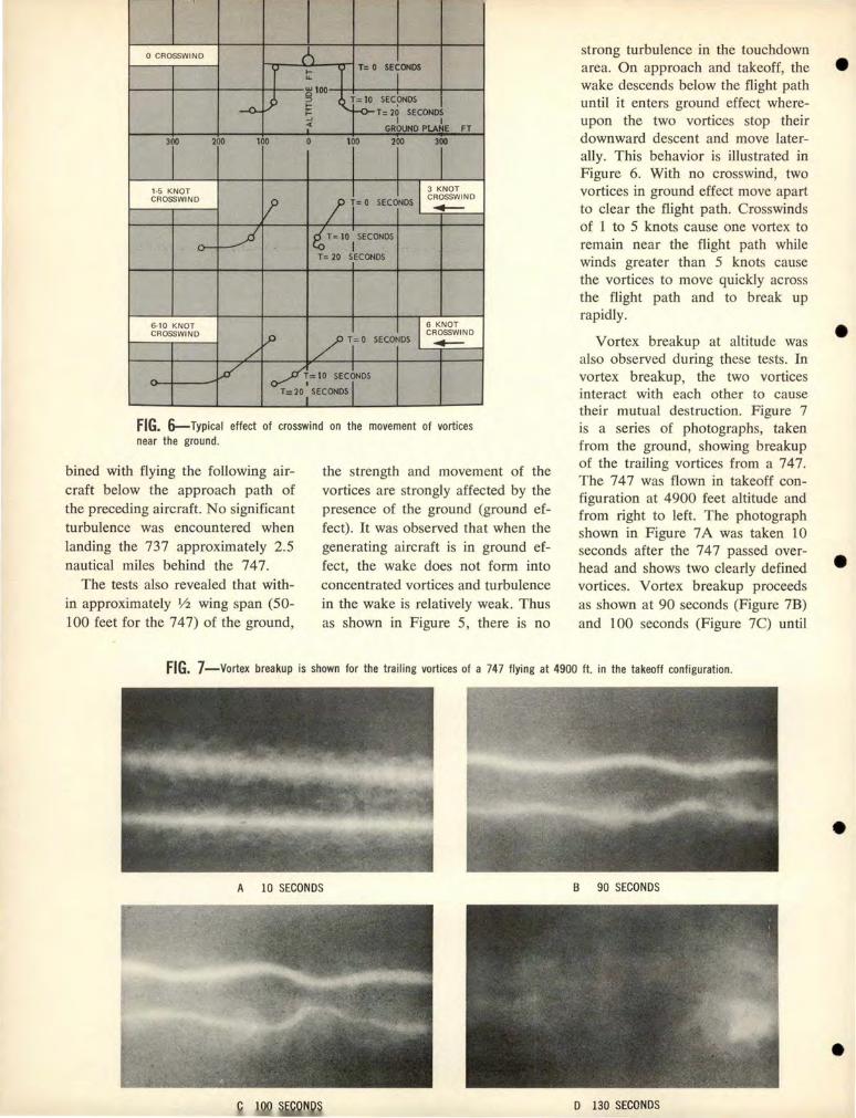
Vortex breakup at altitude was also observed during these tests. In vortex breakup, the two vortices interact with each other to cause their mutual destruction. Figure 7 is a series of photographs, taken from the ground, showing breakup of the trailing vortices from a 747. The 747 was flown in takeoff configuration at 4900 feet altitude and from right to left. The photograph shown in Figure 7 A was taken 10 seconds after the 7 4 7 passed overhead and shows two clearly defined vortices. Vortex breakup proceeds as shown at 90 seconds (Figure 7B) and 100 seconds (Figure 7C) until
FIG. 7-Vortex breakup is shown for the trailing vortices of a 747 flying at 4900 ft. in the takeoff configuration.
A 10 SECONDS B 90 SECONDS
D 130 SECONDS
•
•
•
•
•

•
•
•
•
•
• 747 FLIGHT TEST
V)
w NOTEI CURVE FROM SAE
PAPER el0220 ~ => z ~ ' w
u.. :J ><
4 8Y W. A. MCGOWAN 7•7 DATA SUPERIMPOSED
w ~ OTHER AIRPLANE DATA a:: 0 2 >
o~------'""":"'::--------~--------...._ ______ ......,1 0 1 0 20 30 40
WIND SPEED KNOTS
FIG. 8-- Effect of wind on vortex life for vortices within 500 ft. of the ground.
at 130 seconds (Figure 7D), the two vortices are completely destroyed. This breakup is commonly seen in viewing contrails from the ground. Other investigators have found that breakup occurs more quickly when an aircraft has flaps down and when the atmosphere is turbulent. Within approximately 5000 feet from the ground, vortex life is directly affected by wind speed. The higher the wind speed the shorter is the vortex life (Figure 8).
WAKE TURBULENCE ENCOUNTERS
During the wake turbulence tests, Boeing and NASA pilots intentionally flew into the trailing vortices and attempted to hold the 737 / CV-990 in the turbulence as long as possible. At no time did either aircraft experience control or structural difficulties. The severity of wake turbulence encountered during the tests could be described as being similar to penetrations of moderate clear air turbulence.
The response of an aircraft to typical vortex encounters is illustrated in Figure 9. A jet transport airplane entering wake turbulence will be quickly rolled out of the wake with maximum bank angles on the order of 30°. Yaw may also be experienced, particularly when the wake is approached from below,
so that the vertical stabilizer is first to enter the turbulence. In any encounter, the aircraft is quickly expelled from the turbulence without experiencing unusual attitudes. An airplane will not be 'captured' by the vortex.
A new appreciation has been gained for the turbulence generated behind all transport aircraft. Test data and operational experience indicate that small airplanes (less than approximately 75-ft wing span or 75,000-lb maximum takeoff weight) may require increased separation from jet transport airplanes. Further study should be devoted to the separation requirements for these aircraft. Separation standards should be designed to minimize the possibility of a wake turbulence encounter and ensure that if an encounter occurs, it will not cause a severe upset or structural damage. Pilots of all jet transports should be encouraged to alert ATC if they observe a light airplane whose flight may cross their wake, or if they observe situations which they consider hazardous to light airplanes.
The test results presented here point to one simple but important procedure which all pilots can apply to avoid wake turbulence.
Fly on or above the flight path of the preceding aircraft.
+ c ~
I
+ I. FROM ABOVE (RIGHT)
t
c±:) + +
2. FROM ABOVE (CENT~R)
c ~~-:) --k-
3. FROM SIOE
c r~~ ~)P'
4. FROM SI OE (RAPID)
c 4-~ .+ f.
S. FROM BE LOW (RIGHT)
+ _...._
c ~ ~
+ 6. FROM BELOW (RAPIO)
FIG. 9-Response of an airplane to typical wake turbulence encounters.
CONCLUSIONS
The tests conducted by Boeing have shown that wake turbulence generated by a 747 has the same effect as that generated by other jet transports operating prior to the introduction of the 747. Thus, the data indicates that the 7 4 7 is compatible with transport operations and does not require special separation standards.
ED. NOTE: USAF has elected to retain conservative separation criteria until test data currently being acquired can be fully evaluated. Air Force controllers are directed to afford non-heavy jet aircraft (gross weight of less than 300,000 pounds) a ten mile in-flight or four minute arrival and departure separation behind C-5A and Boeing 747 air
craft . * AUGUST 1970 • PAGE THIRTEEN

L.Al[lAlot:NIS
~'L 0 .
L D
" SECTIONO·D--\ OAJAAGlflf!AA!A
SMOOTH CONIOUI Of.NlS-
The damage limits shown are intended to be typical. There is no intention to display specific damage criteria here. You must consu lt the applicable model technical instructions for exact information.
Bellows being subjected to a bend beyond its allowab le design limits .
Example of a ·4 steel braided flex line not having proper clearance from the bellows.
•ppear1nce of the coll•psed lower bellows •nd stretched upper unit could be • clue lll•t the HMmbly is not inmllmd Comctly.
LEXIBLE BELLOWS, long used in missile and spacecraft, have been put to widespread use in
aircraft. They are frequently seen in jet engine compressor bleed air and fuel supply systems.
Aircraft system designers have found these flexible units particularly suitable because of their ability to absorb thermal expansion and contraction, their installation flexi-
•
A NEW Harold Poehlmann, Fairchild Hiller Corp. Directorate of Aerospace Safety
•
Material for the salvage yard . •
bility and ease of alignment during routine maintenance, and ability to handle both high and low temperatures.
Fine, you say, this looks like real good equipment. Right, but to keep it good we must protect it from damage. This abuse can take the form of dents, cuts, nicks, chafing, improper installation causing outof-limits stretch or bend and any
•
•

•
•
•
•
•
BREED OF CAT
other wounds that "normal" maintenance can inflict. A dent caused by dropping a heavy tool on the corrugations is certain to produce a condition that can lead to rapid fatigue failure. Plumbing, cables or, in particular, a steel braid covered flex line that remains in contact with the bellows will literally " eat" through the thin bellows material in a time period commensurate with the vibration that is present and the contact pressure.
You probably have noticed that some flex ducts are covered with stainless steel braid, some have a heavy rubber cover shield, some possess internal reinforcement or stretch limiting struts. Regardless of construction, all react the same to external damage You would be amazed as to what happens when a low pressure fuel duct bellows develops a crack. The fuel escapes in a spectacular atomized spray, usually resulting in a 4th of July fireworks display. The cracking of a hot air duct produces equally serious inflight problems.
Someone from the back of the room has asked, "What can we do to prevent this?" Good question , we were just coming to this. The intent of this humble essay is to bring primarily two things to the attention of crew chiefs and mechanics: (1) that the service life of bellows ducting units can be shortened if they are allowed to remain in service with damage, and (2) the necessity of knowing where to locate the allowable damage criteria.
Tragic accidents are certain to
develop from duct failure, whether they are conducting fuel, hot air or cryogenics. Reality indicates that maintenance mistakes will be with us till the end of time, but you must be capable of identifying a bellows that shows evidence of damage and detecting a bellows that is grossly out of alignment. You must also be diligent in locating and adhering to the appropriate damage allowance instructions. These usually can be found in the Structural Repair & Limits Manual Dash 3 Series for your aircraft or the Dash 6 Series in the case of engines.
My experience has been that there is a general lack of aware
ness as to what kind and degree of damage is tolerable on flex bellows. The basic design philosophy that can form a section of metal into a highly flexible unit with extraordinary service life is also very unforgiving when the hardware is subjected to damage. When in doubt call your inspection section for their "eagle eye" assistance.
Displayed here are some photos of typical damage along with some sample damage limits. These happen to be in connection with bleed air ducts. Notice the four general classifications: flattened areas, knife edge dents, lateral dents and smooth contour dents. We also draw your attention to the fact that trough or inner convolution damage are "nonos" and " ... no dents, no damage, no nuttin'."
When working in an area of flex ducts, temporarily cover or protect them against wrench slippage or fulcrum action. Do not pry against or stand on any units that might be in a vulnerable position in the lower engine compartment, such as a main engine fuel supply line. Make certain the line assembly is supported and not allowed to stretch a bellows, as when one end is disconnected from the engine. When installing a flex duct unit that has a swivel attachment, insure that the assembly is in proper alignment with all bellows in their normal design contours before securing the swivel connection.
Be suspicious of any bellows joint connection that has flanges that require abnormal gaps, compression or misalignment. This is usually a signal of improper design or installation, or bend damage. Subjecting a bellows to this deformation and stress is "bad news." If a bellows line is in jeopardy of becoming caught or jammed against an engine or airframe during engine removal , either secure it or remove the assembly to prevent damage.
The main object is to be aware of the stringent damage limits, where the data can be located and the need to give these "cats" a thorough 360 degree inspection after any unscheduled maintenance actions in addition to the routine inspection periods. Don't you be the one that played a part in causing high cost "4th of July fireworks out of
season." * AUGUST 1970 • PAGE FIFTEEN

SELFLOCKING
NUTS Gus Musulas,
OOMA, Hill AFB, Utah
During reassembly of aircraft wheels, flight controls, engine controls and other systems,
maintenance personnel sometimes fail to replace worn self-locking nuts. Incident and accident reports frequently contain statements such as "examination revealed bolt was missing," or "visual inspection revealed bolt had become loose."
Serviceable self-locking nuts provide tight connections which will not loosen under vibration. Self-locking nuts approved for use on aircraft meet critical specifications as to strength, corrosion resistance and temperatures. There are two general types: Prevailing torque all-metal nuts designed with a thread distortion to provide the locking action and prevailing torque metal nuts with a nonmetallic insert to provide the locking action.
All metal, self-locking nuts are constructed with the threads in the locking insert out of phase with the load carrying section, or with a sawcut top portion with a pinched-
in thread. The locking action depends on the resiliency of the metal when the locking action and load carrying portions are engaged by bolt or screw threads.
Non-metallic insert, self-locking nuts are constructed with an unthreaded non-metallic locking insert on top of the load carrying section or with a plug inserted in one of the side faces of the nut. The non-metallic insert has a smaller inside diameter than the nut ; therefore, when a screw or bolt is inserted , contact is forced between the insert and the screw or bolt threads, causing the locking action. This type of selflocking nut should not be reused if the locking insert has lost its locking friction or become brittle, and it should not be subjected to temperatures in excess of 12 l °C (250°F).
The locking feature of metal and non-metallic insert type locking nuts 3/s inch and smaller may be checked by the "finger tight" method. If a nut can be run down with the fingers
after the locking feature engages the bolt or stud, indicating locking friction does not exist, it should be replaced. The minimum torque values for use with a standard torque wrench on used self-locking nuts over % inch are given in the table.
In some cases a new metal selflocking nut may not be the answer. For example, a metal self-locking nut that has been turned on and off many times may have worn threads on the stud or bolt to the point where a new nut will not lock. In such cases the only solution is to replace the stud or bolt.
To learn more about self-locking nuts see TO 1-1 A-8 . For example, paragraph 5-29 says, "New selflocking nuts shall be used each time components are installed in critical areas throughout the entire aerospace vehicle including all flight, engine and fuel control linkage and attachments."
Section V has other info you can use. A review is suggested. *
TABLE OF - PREVAILING T09£ VALUES FINE THREAD SERIES COURSE TlllEAD NUT SIZE MINI- PIEVAtUNG NUT SIZE .........
TOllQUE .... 7/16-20 8 inch-pounds 7/16-14 8 inoh-pounds 1/2-20 10 inch-pounds 1/2-13 l 0 iach-poands 9/16-18 13 inch-pounds 9/16-12 14 inoh-pounds 5/8-18 18 inch-pounds 5/8-11 20 inch-pounds 3/4-16 27 inch-pounds 3/4-10 27 inoh-pounds 7/8-14 40 inch-pounds 7/8-9 40 inoh-pounds 1-12 55 inch-pounds 1-8 S 1 inch-pounds 1-1/8-12 73 inch-pounds 1-1/8-7 68 iach-pounds 1-1/4-12 94 inch-pounds 1-1/4-7 88 inch-pounds
NOTE: Threads shall not be lubricated because the torque values of the
chart were derived with oil-free threads. Minimum prevailing torque read
ing is established when the bolt or stud fully engages the locking feature.
PAGE SIXTEEN • AEROSPACE SAFETY
•
•
•
•
•
•
•
•
•
•
CROSS CDUNTR
NOTES
Last weekend I took a trip around the country in my trusty old T-Bird. Just lookin', I call it-some of the others around here say I'm out "Rex-ing." At every stop I was met with prompt, efficient service. The people I met on the ramps, in Base Ops and the snack bars knew their business and were going about it in a way that made me proud of each operation I saw.
I was feeling pretty good about the whole trip until I arrived at Canker AFB. I had run out of crew duty, so I had to RON. When I learned what the messing situation was, I wished I had pressed on to another base for the night. The Officer's Mess was closed to transients because the base was holding a dining-in. No one had seen fit to set aside a small area in the club for feeding transients. I expressed my disappointment to the folks in Base Ops, but they assured me there was no problem-both the Flight Line and Golf Club snack bars were open.
Now, I'd been eating in snack bars all day. I was ready for an honest-to-goodness sit-down meal
/
before I went to bed for the night. The Flight Line snack shack didn't look like it had what I was looking for, so I called a base taxi, waited until it arrived, and went over to the Golf Club. Wouldn't you know it? Nothing available there but cold sandwiches.
I gave up and went to town. The thing that troubled me the
most was the Rex Riley certificate, neatly framed, hanging on the wall in Base Operations. *
LORING AFB McCLELLAN AFB
MAXWELL AFB HAMILTON AFB
SCOTT AFB RAMEY AFB
McCHORD AFB MYRTLE BEACH AFB
EGLIN AFB FORBES AFB MATHER AFB LAJES FIELD
SHEPPARD AFB MARCH AFB
GRISSOM AFB PERRIN AFB
CANNON AFB HICKAM AFB
LUKE AFB RANDOLPH AFB
ROBINS AFB TINKER AFB
WETHERSFIELD AFB HILL AFB
YOKOTA AB SEYMOUR JOHNSON AFB
ENGLAND AFB MISAWA AB KADENA AB
ELMENDORF AFB PETERSON FIELD
RAMSTEIN AB SHAW AFB
LITTLE ROCK AFB TORREJON AB TYNDALL AFB
OFFUTT AFB ITAZUKE AB
ANDREWS AFB McCONNELL AFB
NORTON AFB BARKSDALE AFB HOMESTEAD AFB
Limestone, Me.
Sacramento, Calif.
Montgomery, Ala .
Ignacio, Calif.
Belleville, Ill.
Puerto Rico
Tacoma, Wash.
Myrtle Beach, S.C.
Valparaiso, Fla.
Topeka, Kans.
Sacramento, Calif.
Azores
Wichita Falls, Tex.
Riverside, Cali f.
Peru, Ind.
Sherman, Tex.
Clovis, N.M.
Hawaii
Phoenix, Ariz.
San Antonio, Tex.
Warner Robins, Ga. Oklahoma City, Okla.
England
Ogden, Utah
Japan
Goldsboro, N.C.
Alexandria, La.
Japan
Okinawa
Alaska
Colorado Springs, Colo
Germany
Sumter, S.C .
Jacksonville, Ark.
Spain
Panama City, Fla.
Omaha, Nebr.
Japan
Washington, D.C.
Wichita, Kans.
San Bernardino, Cal if.
Shreveport, La.
Homestead, Fla.

Lt Timothy R. Gavin , San Francisco
I noted
the difficulty
but not
the danger
FROM THE BEGINN ING of my Air Force career I have been drilled in the concept of responsibi lity.
I have always thought I knew exactly what responsibility meant, and I have never seriously doubted my ability to handle any job "responsibly."
A recent mishap has made me reevaluate my outlook on the subject of responsibility, and I hope my thoughts will initiate some new thinking on the part of any supervisor who is charged with, or claims to possess, responsibility.
The event I'm referring to was an accident which may cost the injured airman the sight of an eye.
Our unit is a small enroute maintenance detachment handling cargo aircraft. The day of the accident began normally. We had an aircraft early in the morning and blocked it without incident. I checked the schedule for the remainder of the day and assured myself that we had no aircraft inbound. I had been waiting for a break in the schedule to rearrange the office furniture and finish building a unit picnic area. It looked like an excellent opportunity to get the jobs done.
Work in the office required removal of a plexiglass chart from the wall. After taking off the frame we discovered the original installation of the chart was made by pounding nails through the pre-drilled holes in each corner. Removing the nails was difficult. No one could seem to
PAG E EIGHTEEN • A EROSPACE SA FETY
fi nd a claw hammer and an airman working on the chart was using a screwdriver-forcing it under the plexiglass and trying to pry up the nail in that manner.
I noted the difficulty but not the danger and left the office to find a hammer. I was only a few feet from the office when the airman called me back. When I turned around I saw that he was holding a hand over his eye and saying he should go to the hospital.
On the way over he told me that when he pried up the corner of the chart, a small piece of plexiglass splintered from the chart and lodged in his eye. The rest of the story is in the hospital report. "Airman received a laceration of the cornea of the left eye ... prognosis for return of normal vision is poor ... recommend airman be returned to the United States for specialist care ... possibly a corneal graft."
This accident shocked every member of the detachment. The obvious lessons were impressed on everyone involved. I don't think the dangers of working with plexiglass or the need to use the right tool for the right job will need re-emphasis very soon.
As a supervisor, I have examined my conscience more deeply than perhaps the other members of the detachment. From the moment I saw the airman with his hand over his eye, I knew I had blundered
•
•
•
•
•

•
•
•
•
•
and I knew exactly what I should have done. But why didn't I react?
I believe my mistake was not simply that I neglected to stop the unsafe act but, rather, a kind of creeping complacency toward exercising my responsibility. Most supervisors at one time or another experience this type of complacency. How often have you walked by someone who was doing a job halfright or without proper safety equipment or TOs and not sa id anything? lt may have bothered your conscience, but still, for some reason that probably wasn ' t very good, you simply didn't do anything.
I f I were to ask you now if you think you are a complacent supervisor, I'm sure I wouldn' t get a "yes" answer. If someone had asked me that question the day before the accident, I know I would have answered an unqualified " no. " Today I am a little more self-crit ical. Complacency is tremendously dangerous to any supervisor simply because most of us are unwilling to admit to ourselves that it may exist.
To me the real measure of the supervisor is his ability to "exercise" his responsibility. Like taking care of your body; if you don't exercise it, sooner or later you will pay the price in terms of your health. Likewise, if you fail to exercise your responsibility and are simply "carrying" it, ultimately the price will be paid, and in all probability, in much more tragic proportions. *
LOST and DOWNED BHIEFS OF HECENT AIRCHAFT ACCIDENTS
C 13 0 Four minutes after departure the crew transm itted - that the wing was on f ire and that they would have
to ditch . Observations from another aircraft indi cated smoke coming from the wing area , that one engine was shut down, and the aircraft appeared to be in a ditch ing con figu ration . The aircraft was seen to touch down and hydroplane fo r approximately 70 yards then disappear. Prel iminary investi · gation ind icates possible materiel failure in the bl eed air system .
C 119 Immediately after takeoff, pilot notified tower that - an engine was failing and that he would climb
straight ahead and return for landing. Aircraft was not able to climb even though the propeller was feathered . Landing gear wa s retracted at impact; however, there is a strong possibility that retraction time was prolonged due to an engine being shut down. It appears that the pilot had to sacri f ice altitude to maintain single engine climb speed , but ran out of altitude.
Twenty feet of wing was broken off when the wingt ip struck a dike. Aircraft then crossed a ditch and began to break up. There were two survivors among the eight crewmembers . COMMENT: An intensive program is underway to improve reliability of overhauled R-3350-89 engines. In the interim, takeoff gross weights are being limited to insure single engine climb capability.
C-47 Aircraft was landing after a SEA support mission . A normal touchdown was immediately followed by a swing to the left. This was controlled by the
pilot but a further left swing could not be held. Aircraft left the runway, struck a small mound with the left wheel and came to rest on its nose and main gear. Examination revealed that there was a hole in the wheel rim around the tube stem , dye penetrant checks revealed further cracking of the rim, and it appears that (unknown to the crew) the left tire deflated during flight. Other interesting factors:
• There had been four flat tires on the subject wheel during the preceding ten weeks;
• Pilot occupying the right-hand seat did not have his shoulder harness fastened;
• Flight mechanic was standing-·between the pilots' seats for the landing and not seated and strapped in .
F 1 0 6 During an ORI an F-106 pilot was attempting a - night, over-water, low-level intercept against a
T-33 target. The target was flying at 1500 feet , emitting chaff. The F-106 pilot flew into the water in his attempt to hack the intercept. *
AUGUST 1970 • PAGE NINETEEN

• a good honest bird, reliable and tough
if you let her do what she's designed to do
ORDNANCE CAPABILITY
STATION 8
NOMINAL PYLON CAPACITY IN LBS.
BOMBS AND FIRE BOMBS
ROCKETS
MINES
DISPENSERS
MISSILES (AIR-TO-GROUND)
FLARES
SPECIAL PURPOSE LEAFLET
ECMPODS
FUEL TANK
TOW TARGET
MISSILES (AIR-TO-AIR)
I
PAGE TWENTY • AEROSPACE SAFETY
In the past the Air Force has made fighters out of bombers, bombers out of fighters-in short,
made one airframe do a mu/it-mission job. In many cases the results have been "fair" for both missions. Now happily, we have a new trend. Our in-the-mill F-15 is promised as an air superiority fighter to clear hogies from overhead, while down below, Brother Corsair will do the job of dropping bombs and shooting guns in an attack role.
IT'S MUSIC TO OUR EARS when we hear the Head Honcho say, "She's a good, honest bird, reliable and tough if you let her do what she's designed to do-fill the attack role. " To find out what the jocks think of the A-7D we took a trip to Luke to get the straight skinny. Lt Col Bobby Bond, Commander of the 310th Tactical Fighter Training Sq uadron, and all his boys like the bird! So that everybody will have a feel for what's coming up in the way of hardware, we'll discuss some of the capabilities, characteristics and systems of the Air Force version of the A-7.
To begin with, the A-7D is not the same bird as the Navy A-7A/ B. We required some basic changes which were:
• Increased thrust: 14,250 versus 11,350
• Improved ordnance delivery error (from 20-10 mil)
•
•
•
•
•

•
• A receptable for air refueling boom
• An avionics package improved to provide:
integrated bombing and nav1-e gation capability.
•
•
•
heads-up display (HUD) tactical computer projected map display
• An increased survivability package of:
all foam-filled fuel tanks three separate power control
systems back-up controls, system re
dundancy extensive ceramic and steel
armor ECM
• A 20mm M61-A-l gun
• An antiskid brake system.
FUEL SYSTEM
Looks like a winner. It has no moving parts. Ejector-type fuel
MID TANKS
FORWARD TANKS
SUMP TANK
EXTERNAL TANKS (UPT04 -CAN BE CARRIED)
pumps transfer fuel from the wing and aft cell into the sump cell. This sump plus the lower one-third portion of the aft fuselage cell are selfsealing and give the pilot a hip pocket 300 NM of gas in the event of damage to the rest of his system. Total internal fuel available is a bit over 9500 lbs. It's enough, so the troops at the squadron say, to fill 'er up once in the morning and fly all day long. A jettisoning feature is available to get rid of all wing fuel
AUGUST 1970 • PAGE TWENTY-ONE

A-70 CONTINUED
(720 gallons) by gravity flow within 7.5 minutes.
ESCAPE SYSTEM The bird has an improved escape
system which includes an automatically deployable survival kit and a ballistically initiated canopy jettison. The standard face curtain and between-the-legs D ring are used to initiate the sequence. The limits are 0-650K and from 0-50,000 feet.
TAKEOFF PERFORMANCE GROUND ROLL DISTANCE
12,000
10,000
ti: 8,000 I
w (.) z 6,000 <( I-(/)
0
4,000
2,000
0 24,000 28,000 32,000 36,000
TAKEOFF WEIGHT- LB
LEVEL FLIGHT V MAX 50',000
CLEAN PLUS 4 WING PYLONS
40,000 ~
ti: 30,000 I 4-1,000LB .
LDGPBOMBS w Cl ::> I-~ 20,000 <(
10,000
0 0.65 0.70 0.75 0.80
MACH NUMBER
0.85 0.90 0.95
PERFORMANCE To give you a feel for how the
A-7 goes about its mission , we've reprinted some simplified takeoff, climb data, and level flight V max charts which indicate that even without A/ B it's not exactly a hog.
NAVIGATION The airplane has four (count 'em
-four) dead reckoning nav modes, all dependent on sensor availability. They are:
• Doppler-Inertial Gyrocompassing (DIG)
PAGE TWENTY-TWO • AEROSPACE SAFETY
•
•
•
•
•

•
•
•
•
•
CLIMB PERFORMANCE STANDARD DAY
20
120
:::!:: z 130 I
UJ (.) z <t: I(/)
Ci 40
0
1,600
1,200
Q) _J
~ 800 UJ ::J u_
400
0 0 10 20 30 40 50 60
ALTITUDE-1 ,000 FT
• Doppler-Inertial (DI) • Inertial • Doppler/ Air Mass Doppler-Inertial is the primary
navigation mode; automatic change over to backup navigation modes occurs in case of navigation sensor failure. The navigation systems will automatically assume, or can be manually selected to, a pure inertial
mode if the Doppler is unreliable. The Doppler/ Air Mass mode will be assumed automatically if the Inertial Measurement System fails. If the air-data computer fails, the latter mode will continue on Doppler data and magnetic heading. If the Doppler fails, the mode will use true airspeed, magnetic heading and last computed wind from storage.
RADAR Equipped with FLR (forward
looking radar) the A-7D is capable of high or low altitude mapping, low altitude terrain following, low altitude terrain avoidance, air-to-ground ranging plus two cross scan modes which allow simultaneous terrain following and terrain avoidance or terrain following and low altitude mapping. For terrain avoidance, clearance altitudes can be programmed for 200, 500, 1000, 1500 and 2000. Also built into the set is beacon interrogator for Ku band beacons. This feature also gives range and azimuth to the beacon.
THE HUD This isn't a revival of an old
movie-it's, according to the A-7 jocks, magic. How many times have you been on final for an approach to a 2001h ceiling and wished you could ignore the gages and just look for some solid concrete? Well, it looks like the HUD (heads up display) has just solved this little dilemma for us. In effect, this gadget takes all the necessary information from the flight instruments and displays pertinent data at eye level (similar to the gun sight). The display is transparent, focused to infinity, and optically merges to become part of the pilots forward view. We have reproduced the HUD symbology and a typical HUD landing display to show you what information you, as an A-7 driver, can expect to see. We in the safety business welcome the HUD as a real break-
AUGUST 1970 • PAGE TWENTY-THREE

A-70· CONTINUED
through in eliminating the crossed eyes method about the time you expect to go visual on an instrument approach. It eliminates the eyes bouncing from gages on the panel to windscreen. Jn addition to the landing mode the HUD is used for attack and enroute navigation.
PAY LOAD Since we have identified the A-7D
as an attack weapon, the accompanying load configuration chart shows various ways to hang the business equipment. Another good feature is that the aircraft has a respectable radius of action even when max grossed. This coupled with an improved target accuracy factor (10 mils vs 20 mils) means that for a 95 per cent Pk you need only one-third the number of sorties to clobber a target. Good news if you're the one laying it on the line.
Far from being a needle nosed fighter, this bird promises to be a real work horse. It looks to us and to the troops flying her that the A-7D will perform "as advertised." *
SINGLE POINT PNEUMATIC SERVICING
LANDING PHASE
QUICK ACCESS TO AVIONIC COMPONENTS
ENGINE BORESCOPE INSPECTION
BUILT-IN HAND PUMP ALL UTILITY SYSTEMS
ENGINE OPERATIONAL CHECK WITH PANELS REMOVED
_ __/ !/
MAINTENANCE FEATURES The A· 70 was designed and engineered to
facilitate maintenance and to keep turnaround time at a minimum. These features include:
• Single locaton checkout panel for: voltages, phase checks, flap indication circuit
• Waist-high gun, both for maintenance and loading
• Built-in hand pump for all utility hydraulic systems
• Built-in phase sequence light for external power
• Simplified servicing of l iquid oxygen system
• Fast access to avionic components • Single location for pneumatic servicing • Simplified system for refueling and
defueling • Single oxygen converter with easy access
for filling in place or for quick removal for filling or maintenance.
SINGLE LOCATION CHECK-OUT PANEL
•
•
•
•
•

•
•
Ops topics SHORT BURSTS FOR OPERATORS
FROM AN OHR
" .. Shortly after starting, I removed the seat safety pin . I always visually check the pin after removal. On this occasion inspection showed that the outer housing of the pin shaft separated at the neck leaving the outer housing still in the seat. The inner shaft and pin handle extracted normally. Had I taken off with this condition, the ejection seat would have been inoperative."
This one occurred in an F-106, but it could happen anywhere that this type of ball-lock pin is used. The unit involved in this incident inspected the rest of their aircraft and found three more seat pins with loose shafts .
The lesson, of course-LOOK at the pins after you e pull them.
•
•
A few EURs have been submitted on this condition -it usually is the result of age and wear. On some aircraft the Dash 6 now includes a specific check of all ball-lock pins. If it isn't part of the inspection requirements for your aircraft, how about firing in an AFTO 22?
B-57 DISASTER
Following a simulated flameout pattern, the pilot of the B-57 planned a low approach, but when he added power the aircraft continued to sink. It touched down on the overrun 650 feet short of the runway, became airborne again for 1300 feet and touched down again in a violent rolling pitching movement. The bird left the runway on a collision course with Base Ops. It veered to the right slightly, passed between two rows of parked aircraft, and struck three military vehicles and two loading stands. An explosion followed . The vehicles were destroyed and the front of Base Ops was damaged .
After disconnecting from the seat, the front seat pilot attempted to blow the canopy by raising the right arm rest. The seat went along with the canopy, launching the pilot 30-40 feet in the air .
Score: student pilot-major mJunes; pilot-third degree burns; AlC-fatal; fireman-minor cuts; three vehicles and two passenger loading ramps destroyed ; B-57 destroyed; damage to Base Ops.
Primary Cause was Supervisory Factor in that the IP allowed the pilot to stall the aircraft during the low approach following an SFO pattern.
TOO MANY POUNDS
An OHR points up an age-old problem that still pops up from time to time. This time a KC-135 was loaded with cargo manifested at 9000 lbs. Prior to loading, the aircraft was at max takeoff weight so the fuel load had to be reduced by 9000 lbs. It wasn't long before the pilot realized that the aircraft was not performing normally for the computed weight. Then during landing approach the speed deviation pointer in the flight director system indicated slow, making it necessary to increase pattern and approach speed.
If you guessed that the cargo weight was erroneous you are right. Instead of 9000 lbs, it weighed 13,700 -a little matter of 4700 excess pounds. This is one area where the flight crew is strictly at the mercy of the cargo handling crowd. No pilot or loadmaster can eyeball a crate--or whatever-and accurately guess its weight. Organizations responsible for cargo handling and manifesting must insist on accurate manifests showing precise weights. Failure to do so has and will no doubt continue to cause accidents.
AUGUST 1970 • PAGE TWENTY-FIVE

Ops topics CONTINUED
A-7 OIL FILLER CAP
On runway prior to takeoff, wingman noted heavy vapor mist coming from aft port side of section leader's aircraft. Leader aborted, taxied clear of runway and secured the engine. Investigation revealed that the oil filler cap was not properly installed while failsafe door would close.
The aircraft was received new with the oil filler cap security assembly out of adjustment, allowing the door to be closed with the cap improperly installed. If the wingman had been positioned on the opposite side of the subject aircraft, the oil loss might have gone undetected and a very serious situation might have developed shortly after the aircraft became airborne.
Recommend that pilots and support personnel inspect the oil filler cap very carefully prior to each flight.
(U.S.N. CROSSFEED)
GEAR GRABBER
When the T-Bird taxied in from an FCF, the crew chief noticed fuel leaking from the underside of the left tip tank. Checking closer, he saw that the bottom of the tank was dented and scraped. Getting curious, he looked the bird over and found the bottom edge of the left main gear door was scraped, too!
PAGE TWENTY-SIX • A EROSPACE SAFETY
The pilot had been unaware of any unusual occurrence during the flight that could have caused the damage. The strange part of it was that there was no way the gear door could have been scraped like that unless the left tire was deflated, and it wasn't! That is, if the gear was down and locked.
Now, if the pilot had started the gear up before the bird was really airbome----
But there's more to this one :
The pilot was qualified in both the T-39 and the T-33. And the T-39 rushes right off the ground when you rotate for takeoff. Not so the trusty old T-Bird. Maybe some habit interference?
'Specially on these hot summer days-and in any airplane, old or new-it makes real good sense to be double sure the bird's flying before you grab the gear.
GEAR DOWN AND CHECKED? Maj Leland P. Kriner, Directorate of Aerospace Safety
After completion of several practice instrument approaches, the pilot of an F-84F commenced his landing approach. When the aircraft was two miles out on final , the runway supervisor observed that the taxi light was not illuminated and asked the pilot to recheck the position of the landing gear. The pilot replied that the gear was down and locked. Shortly thereafter, the aircraft skidded to a halt resting on the external fuel tanks. Fortunately the pilot was not injured and the aircraft damaged only slightly. With all that help ... ?
Regrettably, this type of human error is not an isolated case. Much too recently, this mistake was duplicated with an F-4 and an F-105.
•
•
•
•
•
•
•
•
•
•
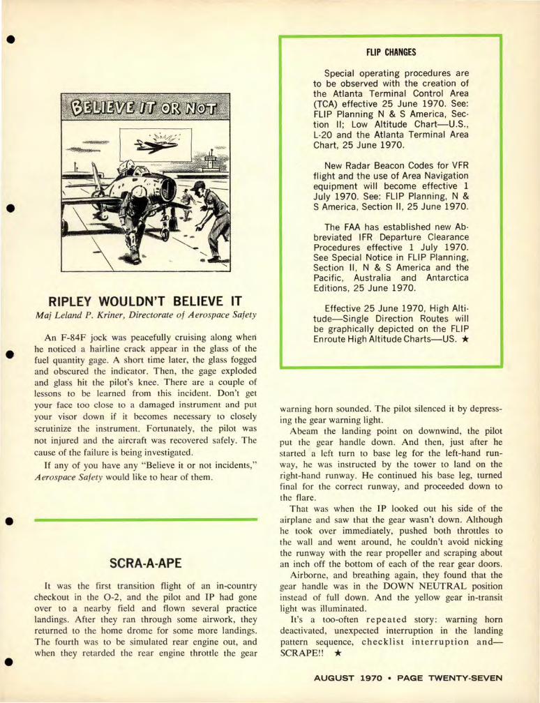
RIPLEY WOULDN'T BELIEVE IT Maj Leland P. Kriner, Directorate of Aerospace Safety
An F-84F jock was peacefully cruising along when he noticed a hairline crack appear in the glass of the fuel quantity gage. A short time later, the glass fogged and obscured the indicator. Then, the gage exploded and glass hit the pilot's knee. There are a couple of lessons to be learned from this incident. Don't get your face too close to a damaged instrument and pul your visor down if it becomes necessary LO closely scrutinize the instrument. Fortunately, the pilot was not injured and the aircraft was recovered safely. The cause of the failure is being investigated.
If any of you have any "Believe it or not incidents," Aerospace Safety would like to hear of them.
SCRA-A-APE
It was the firs t transition flight of an in-country checkout in the 0-2, and the pilot and IP had gone over to a nearby field and flown several practice landings. After they ran through some airwork, they returned to the home drome for some more landings. The fourth was to be simulated rear engine out, and when they retarded the rear engine throttle the gear
FLIP CHANGES
Special operating procedures are to be observed with the creation of the Atlanta Terminal Control Area (TCA) effective 25 June 1970. See: FLIP Planning N & S America, Section II; Low Altitude Chart-U.S. , L-20 and the Atlanta Terminal Area Chart, 25 June 1970.
New Radar Beacon Codes for VFR flight and the use of Area Navigation equipment will become effective 1 July 1970. See: FLIP Planning, N & S America , Section II , 25 June 1970 .
The FAA has established new Abbreviated IFR Departure Clearance Procedures effective 1 July 1970. See Special Notice in FLIP Planning, Section II, N & S America and the Pacific , Australia and Antarctica Editions, 25 June 1970.
Effective 25 June 1970, High Alti· tude-Single Direction Routes will be graphically depicted on the FLIP En route High Altitude Charts-US. *
warning horn sounded. The pilot silenced it by depressing the gear warning light.
Abeam the landing point on downwind, the pilot put the gear handle down . And then, just after he started a left turn to base leg for the left-hand runway, he was instructed by the tower to land on the right-hand runway. He continued his base leg, turned final for the correct runway, and proceeded down to the flare .
That was when the IP looked out his side of the airplane and saw that the gear wasn't down. Although he took over immediately, pushed both throttles to the wall and went around, he couldn't avoid nicking the runway with the rear propeller and scraping about an inch off the bottom of each of the rear gear doors.
Airborne, and breathing again, they found that the gear handle was in the DOWN NEUTRAL position instead of full down . And the yellow gear in-transit light was illuminated.
It's a too-often repeated story: warning horn deactivated, unexpected interruption in the landing pattern sequence, checklist interruption andSCRAPE!! *
AUGUST 1970 • PAGE TWENTY-SEVEN
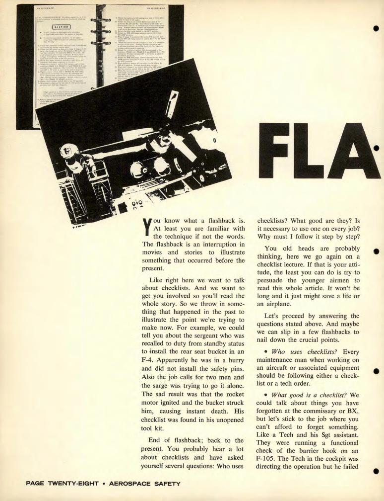
··=:~ ... "':~"";.~~""""~"""'"'~"' I~. ::-:~~1!~1~1: .. ~:i.~r~,
:·:1..::-:..:":'~~::!:::;~ .._, ~ ~:~::::::.';.~~:;;.~~~;rn·;t:_
tMAMf -~, ..... . :~ . ...... .,, ......... ~#V ..... !1,, ... l!..(:~ ....... --
=-~::"·~""'f<-'~··"""' •)•<>< ... MAMS'
H.n""11eai._.,.,,.,•~l'lJ...-w! ... ,., ..... "'*-"".,,"• .. "'°t•••"•l••V.,......_,_.,._ i.10· •.• ,,.u._,_..,i..101~1•,...fll<.,,.~
Ii ;:;:~·,:·~=·..:~.,.,...,_.,o,1.,.,.,, .. , ... ,..._.,-.l'llMXl - l . PJ<"HS-J-~l'!·l.~-
1,. E'::~~ ~~!~=::: :~:: ::·:" AM" l'"~IO> _, J< ><~ ~ ,._. f n, ,_. ""'"~ (H! \0. >lo.·OPr--
1' l" .. ,..,.,..,_,.,.,,...,.,.<!l,zU"'•" ... ~' •11-)tll~I>· ilf'6(,l'""""'"'y'"" ............... _"' ... '"'"
u. ~.: .. ":.!~.!,t.;, ;;,:~:c·~;r..!· _. 1~. ::";..,':;.. ~:~'::':. ~ .... ~ ... ,._
Ill. ~;~J=/1! :"''~ ..... ~
Y ou know what a flashback is. At least you are familiar with the technique if not the words.
The flashback is an interruption in movies and stories to illustrate something that occurred before the present.
Like right here we want to talk about checklists. And we want to get you involved so you'll read the whole story. So we throw in something that happened in the past to illustrate the point we're trying to make now. For example, we could tell you about the sergeant who was recalled to duty from standby status to .jnstall the rear seat bucket in an F-4. Apparently he was in a hurry and did not install the safety pins. Also the job calls for two men and the sarge was trying to go it alone. The sad result was that the rocket motor ignited and the bucket struck him, causing instant death. His checklist was found in his unopened tool kit.
End of flashback; back to the present. You probably bear a lot about checklists and have asked yourself several questions: Who uses
PAGE TWENTY-EIGHT • AEROSPACE SAFETY
checklists? What good are they? Is it necessary to use one on every job? Why must I follow it step by step?
You old heads are probably thinking, here we go again on a checklist lecture. If that is your attitude, the least you can do is try to persuade the younger airmen to read this whole article. It won't be long and it just might save a life or an airplane.
Let's proceed by answering the questions stated above. And maybe we can slip in a few flashbacks to nail down the crucial points.
• Who uses checklists? Every maintenance man when working on an aircraft or associated equipment should be following either a checklist or a tech order.
• What good is a checklist? We could talk about things you have forgotten at the commissary or BX, but let's stick to the job where you can't afford to forget something. Like a Tech and his Sgt assistant. They were running a functional check of the barrier hook on an F-105. The Tech in the cockpit was directing the operation but he fa iled
•
•
•
•
•
•
•
•
to require audible responses from his assistant back in the tail. The man in the tail moved right along through several steps to installation of the explosive bolt. Then the Tech Sergeant in the cockpit depressed a button which energized the explosive bolt circuitry. Since the man in back had the bolt in his hand, you can imagine the rest.
If these two had been following the checklist together ... well, you take it from there.
Here's one that sounds like it came out of a Keystone Cop episode. Only it was ninety thousand dollars serious. A TF33 engine broke loose from a test stand and traveled 286 feet. Yep, "failure to comply with the TO."
• ls it necessary to use a checklist on every job? TO 00-5-1 says that we will operate and maintain our machines by the use of TOs. It also recognizes that some tasks do not require checklists. Nevertheless, we're going to answer this question with a yes and trust you and your supervisor to know when to use or not to use a checklist. Even though
you know your job thoroughly, our equipment today is so complicated and the results of a mistake so drastic that it just makes sense to use every bit of smarts available to do the job right-even using a checklist. Not only will it help protect you, in case of an interruption or if your mind wanders a bit, but it will also protect the guy who will be driving that bird and maybe some crew and passengers.
• Final question, "Why must I follow a checklist step by step?" Some checklists are designed so that if you miss a step you can't go on to the next one. For example, if step four calls for turning on the power and step five is checking a light, obviously there won't be a light unless step four was complied with.
The first item on most checklists is check the aircraft forms. You might get away with servicing LOX, for instance, for years without checking the forms. On the other hand, you might blow· up the next bird you try to service.
Now, let's flash back again to
some incidents that should cinch our case. See what you think.
An F-4 lost a door in flight which caused damage to an AIM-7 missile . Maintenance did not follow the checklist and improperly installed the door.
An F-101 pilot had to shut down N r 2 because of loss of oil pressure. When installing the CSD someone neglected to use a clamp on the oil line as called for in the TO.
A fire warning light caused an 0-2 pilot to shut down the rear engine and make a single engine landing. The rear engine fire detection lead was improperly installed and chafed on the exhaust manifold. Another case in which the TO wasn't followed.
The fact that these examples could go on for pages does not excuse the next one. One thing we can be pretty sure of is that anyone who has ever been involved in an accident in which checklist discipline was a primary cause factor will not be likely to make that mistake again. Which brings up the question, "Do we really have to learn the hard way?" *
AUGUST 1970 • PAGE TWENTY-NINE

UC LEAR
ID
TAT ION
PAGE THIRTY • AEROSPACE SAFETY
AGAIN, AND AGAIN, AND AGAIN!
The last issue of the Nuclear Safety Magazine carried an AID Station on bent pins. Since that article was written, several reports of bent pins on the reentry vehicle inflight-separation cable have been received. An engineering study is underway to determine the feasibility of redesigning the cable connector to eliminate this problem . However, even if a design change is forthcoming, it will probably be months before the change can be affected in the fleet. In the meantime, technicians and supervisors should place extra emphasis on carefulness when mating electrical connectors.
•
•
•
•
•

VIBRATIONS LOOSEN CONNECTIONS
During a commercial power fluctuation at a Minuteman Launch Control Facility, the motor generator coasted to a stop because the back-up DC motor did not pick up the load. Investigation revealed a loose cable connector that prevented the batteries, which power the DC motor, from becoming adequately charged. The cause was attributed to vibrat ion that loosened a connector which had not been properly tightened. Be certain critical fittings are tightened properly.
THE WRONG MOVE
During an ORI, the Deputy Missile Combat Crew Commander inadvertently placed the enable switch in the enable position , thereby violat ing the weapon system safety rules. An increase in tension during the ORI may have been a contributing factor to the violation . During times of stress and excitement , everyone must exercise extraordinary concentration on and awareness of the task being performed. " Keep your cool."
AUGUST 1970 • PAGE THIRTY-ONE

CONTINUED
'I
IUCLEAR
SAFETY
110
STATION
PAGE THIRTY-TWO • A EROS PACE SA FET Y
TOO CLOSE FOR COMFORT
When a civilian veh icle ran a stop sign in front of a slow moving R/ V convoy, the escort vehicle stopped suddenly to avoid a collision. The R/ V van following tried to stop, but ice on the roads prevented adequate traction . A sprained neck and damaged bumper were the results . The absence of major injury and damage are attributed to the slow speed of the convoy, but obviously slow speed alone is not always enough. Proper lookout and sufficient distance between vehicles must be adjusted for road conditions . Defensive driving will prevent the "other guy" from getting you into trouble.
•
•
•
•
•
CHECKLIST PROCEDURES
While loading a 843 on an F-4C centerline, a pull
out cable was damaged . Failure to remove the aft
cable fairing cover resulted in the inability to hold
the pullout cable out of the way while the weapon
was being raised. The oft repeated adage of "follow
checklist procedures" still holds.
WATCH THAT NEXT STEP
Recently at two different Air Force bases, indi· viduals who had received appropriate nuclear safety training stepped across the security boundary (red line) into the No-Lone Zone around a B-52 alert aircraft. In one case a man was delivering a battery to the aircraft and in the other a man stopped to check a work stand underneath the aircraft rear hatch. Although neither case was intentional, they caused prompt action by the security personnel. The NoLone Zone and Two-Man Policy are a vital part of the nuclear safety program. Remember the No-Lone Zone means "stay out" unless properly cleared into the area.
AUGUST 1970 • PAGE THIRTY-THREE
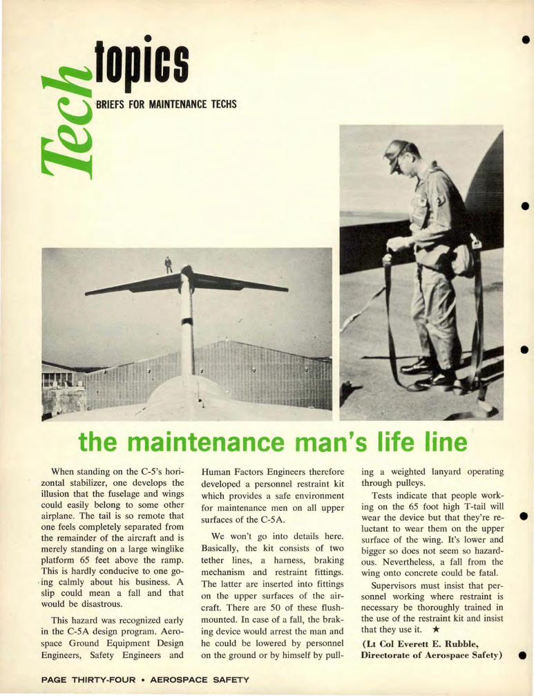
~topics ~'BRIEFS FOR MAINTENANCE TECHS
~
• l
the maintenance man's life line When standing on the C-5 's hori
zontal stabilizer, one develops the illusion that the fuselage and wings could easily belong to some other airplane. The tail is so remote that one feels completely separated from the remainder of the aircraft and is merely standing on a large winglike platform 65 feet above the ramp. This is hardly conducive to one go-
. ing calmly about his business. A slip could mean a fall and that would be disastrous.
This hazard was recognized early in the C-SA design program. Aerospace Ground Equipment Design Engineers, Safety Engineers and
Human Factors Engineers therefore developed a personnel restraint kit which provides a safe environment for maintenance men on all upper surfaces of the C-5A.
We won't go into details here. Basically, the kit consists of two tether lines, a harness, braking mechanism and restraint fittings. The latter are inserted into fittings on the upper surfaces of the aircraft. There are 50 of these flushmounted. In case of a fall, the braking device would arrest the man and he could be lowered by personnel on the ground or by himself by pull-
PAGE THIRTY-FOUR • AEROSPACE SAFETY
ing a weighted lanyard operating through pulleys.
Tests indicate that people working on the 65 foot high T-tail will wear the device but that they're reluctant to wear them on the upper surface of the wing. It's lower and bigger so does not seeni so hazardous. Nevertheless, a fall from the wing onto concrete could be fatal.
Supervisors must insist that personnel working where restraint is necessary be thoroughly trained in the use of the restraint kit and insist that they use it. * (Lt Col Everett E. Rubble, Directorate of Aerospace Safety)
•
•
•
•
•

. .._ ________________________________________________________________ __
•
•
•
•
free water limit What free water limit should be
imposed on JP-4 received at the base? This question has resulted in some confusion by base quality control personnel. Although not specifically stated, Section V, paragraphs 5-10 through 5-15 of TO 42B-l-l, implies that 20 ppm is the free water limit on receipt of product from the various transportation modes.
The intent of the 20 ppm limit is to impose restrictions on product downstream of filter separators to
During taxi for takeoff the nosewheel steering of a C-130 failed and the engineer deplaned to inspect the steering mechanism. When he looked into the nosewheel well he was greeted with a face full of hydraulic fluid from ruptured hydraulic lines. His inspection revealed that both nosewheel steering actuators had pulled out of the fulcrum bearings and several hydraulic lines were broken.
Back on the parking ramp further inspection revealed that two keys were missing from the nosewheel steering bracket (TO 4S3-54-4, fig. 2, index 73). They had either been
insure the filter separator is performing as designed and, of course, to prevent servicing of water to aircraft. Thus the limit should be applied only at fillstands, hydrant pump-houses, refuelers, and hose carts. The procedure for detecting water content of product upstream of these filter separators, which includes receipt, is by the visual technique.
(Aerospace Fuels Digest, SAAM A)
no steering left out during depot overhaul or by local personnel when they installed power cylinders. Also the lock screw (index 66) for the cylinder mounting plate nut (index 67) had been interchanged with the nose landing gear gland nut lock screw (index 31 ).
The two screws are identical except that the gland nut lock screw is shorter. When it is installed in the cylinder mounting plate it does not engage the slots in the thread area of the strut. This nut became loose and allowed the steering cylinder support bracket to turn freely since it was not keyed to the strut. This also increased the dimension between the upper and lower cylinder mounts and allowed the cylinders to be forced from their mounts.
Murphy's law was working overtime here to foil the best intentions of any inspector since the only pos-
sible way to detect the wrong lock screws is to remove and inspect them for proper length. An AFTO 22 was submitted to clarify the installation of the keys. *
quadrant • Jam
While attempting to adjust the throttles to obtain desired airspeed, a student pilot in a T-38 found that the right engine would not go below 98 per cent. He shut the engine down and made an uneventful single engine landing. When Maintenance investigated they found that an Airloc fastener was lodged between the right main throttle control cable quadrant and its housing. *
AUGUST 1970 • PAGE THIRTY-FIVE

• ..;:: 0 ICS ~ CONTIN UED
~ -
inventory everything! The F-4 was scheduled for an
early morning launch and, as often happens, the crew chief was conducting his preflight in the dark with the aid of a flashlight. He checked the intakes for FOD and signed them off in the 7 81 . When he got to the left speed brake area, he found a small hydraulic leak. Uncertain whether it was a bona fide leak or just residual fluid, he decided to run an engine to determine whether the system required further maintenance.
Following the engine runup cards carefully, he inspected the right engine intake for FOD again and in-
the imprint
of death
ventoried tools. With everything in readiness, he climbed into the cockpit. Just as the engine started to accelerate, the man handling the interphone on the ground called that sparks and vari-colored flames were coming from the tailpipe. The crew chief shut down immediately.
Using the ground man's flashlight, the crew chief saw that most of the visible portion of the compressor had been damaged by a metallic object. Later, the engine shop found small pieces of battery in the engine. And the crew chief couldn't find his flashlight. *
The caption says "One of the most remarkable pictures ever taken." We wish we could show you the photo that caption goes with but we can't. It appeared in a British newspaper-which one is unknown -and shows the imprint of a man's body engraved in the grimy ceiling of a garage. The story that goes with it describes what happened. A mechanic was filling a tractor tire with air when he was called to the
PAGE THIRTY-SIX • AEROSPACE SAFETY
~ -7/ \ .. clamp
scare The back-seat pilot in a T-38 was
raising his seat from the full down position shortly after engine start, when the M-32 lap belt and manseat separator initiator fired. With the sound of the explosion, the black smoke filling the cockpit around him, and the butt-snapper slamming him against the stick and the instrument panel, he was sure he was being ejected!
When the smoke cleared, and he recovered from the near cardiac arrest, egress specialists found what had gone wrong. Improperly positioned hose clamps on the oxygen supply line caught on the linkage to the lap belt and the man-seat separator. Fortunately, it all happened on the ground.
Inspection of all T-38s on the field revealed nine others in the same condition, requiring immediate corrective action. *
phone. He forgot to turn off the air and the pressure in the tire continued to build. When he returned and saw what had happened, he started to disconnect the air supply. That's when the tire blew, propelling him against the ceiling and instant death.
Of course, in the Air Force we cage all high pressure tires every time. Don' t we? *
•
•
•
•

•
FOO Anyone who has been in mainte
nance very long can tell you that FOD comes in all sizes and shapes and from an untold number of sources. A couple of recent examples will serve to point up that there are different kinds of FOO but that the end effect-an accident--can result from any kind.
An HH-3 helicopter was taxiing out for a scramble takeoff when maintenance men heard a sound that resembled a compressor stall coming from Nr I engine. Along with it was a puff of smoke followed by flames in the engine free turbine area.
• The pilot. unaware of the situa-tion, continued to taxi until a crew chief ran out to stop him and inform him of the fire. After the engine was shut down maintenance discovered that a rag had been jngested into the N r I engine.
The other incident was somewhat different. An engine on a T-37 got sick and the pilot had to shut it down and make a single engine landing. The cause was found to be oil pump failure due to FOD and subsequent failure of the Nr 2 bearing. The foreign object was a piece
• of a bearing cage from a previous bearing failure. The system had been flushed but because the PA 661 flushing machine was out of order, pressure could not be used for flushing. Consequently, a halfinch length of bearing housing remained undetected in the system. *
~
~ crossed wires
This item, borrowed from the Navy Crossfeed, concerns an ageold malpractice that sti ll crops up frequently , sometimes with drastic results. "During pilot turnup for test flight after engine installation, generator would uncouple when electronic gear was switched on . Maintenance personnel received shocks in wheelwell area.
After many hours were expended
on troubleshooting the system and component changing, the problem was diagnosed as improper wiring between generator and D.P.U. current transformers. Wires to T302 and T303 were crossed causing proper wiring of TS and T6 at generator to be ineffective. System functioned before engine change because TS and T6 at generator had also been crossed to conform to improper wiring of D.P.U." *
another taxi tangle While taxiing out of the chocks,
an F-106 crumpled its left wingtip on an MA-3. Prior to the incident the pilot had made a walkaround but had not noticed the MA-3 , nor did the crew chief notice the hazard.
A crunched wingtip is usually regarded as a minor annoyance, but it costs money to repair, takes time and manpower and temporarily grounds an airplane. Occasionally it can lead to a major accident.
These are reasons why we can't afford "fender benders" with airplanes on the flight line. In this case, the pilot should have been more observant. The crew chief certainly should have taken note of the parked unit and directed the pilot around it or had it moved. The third culprit was the supervisor who allowed the MA-3 to remain parked on the ramp after it was no longer
needed. * AUGUST 1970 • PAGE THIRTY-SEVEN
for munitions, weapons, and egress techs
SOMETHING NEW IN EXPLOSIVES ACCIDENTS Most of us in the explosives safety
business believe that we are either familiar with, or have heard of all conceivable types of explosives accidents. Most accidents are variations of ones which have occurred previously. But here's one that almost qualifies as a new type accident.
ment punctured the leg of another man who was in the vicinity.
The foreign object was a 20 mm HE projectile.
Now you people in the tire shops have something else to look out for. When vehicles are operated in munitions areas or combat conditions, be alert to the possibility of contamination of tires by explosives
•
•
A tire repairman was engaged in repairing 12 ply tires from "M"
series tractors. During the inspection of one tire, he discovered a cylindrical foreign object sticking in the tread. He attempted to pull the object out, but it wouldn't budge. He then attempted to drive the object through the tire and remove it from inside. He struck the object once with a steel hammer and nothing happened. When he struck the object the second time, it detonated, seriously wounding him, and a frag-
items. e (George W. Williford, OOAMA.)
EXPLOSIVES SOUVENIRS Unauthorized explosives taken
(and left) aboard aircraft by passengers continue to be a headache. The primary reason, of course, is the hazard they present. Also a great deal of time and manpower are consumed in investigating the circumstances for preventive purposes.
When a certain type of practice grenade was found on a C-141 recently, many people had to devote valuable time tracking down the source, a very difficult task. The Wing safety folk first contacted an army installation where the aircraft had supported an exercise. This particular device was not used in the exercise and the installation had no record of having received or used this munition.
Next they checked with the am-
munition plant and found out where that lot number of the munition in question had been distributed. But aircraft records for five months showed no flights to the country where these munitions had been shipped. However, on two recent missions from an overseas base passengers were manifested from where the grenades had been used. It was assumed, therefore, that one of them could have carried the grenade aboard the aircraft-probably as a souvenir that the individual had second thoughts about.
Further checking with the overseas ammo depot nailed down the exact location of this explosive in six units. They control the issue by count and shakedown inspections after range use. They also run a
PAGE T HIRT Y-EIGHT • AEROSPACE SA FETY
shakedown prior to PCS. Still explosive devices get through and are later found on aircraft.
Sometimes customs inspections turn up explosives, as when several flares were found recently in an individual's hand baggage. Undoubtedly, though, some explosives get home with individuals returning from overseas and frequently we see the results in casualty reports or newspaper stories.
Overseas stations must continue to brief passengers on the hazards of carrying explosives and of leaving them in aircraft. "Last Chance" boxes for disposal of these items should be prominently placed and marked and all passengers informed as to their location and function.
•
•
•
•
•
•
•
PAD PROBLEMS Accidental firing of propellant
actuated devices (PAD) continues to be a major problem associated with Life Support Equipment. In practically every instance where the cause could be determined, the accident has been due to circumstances which can be classed as avoidable. Here are the most frequent causes:
• Use of unserviceable safety pins, improper installation of pin, or failure to install initiator safety pin prior to working with or near the egress systems.
• Personnel errors in component installation.
• Inadequate supervision .
• Lack of familiarity with the Life Support Systems due to inadequate training.
• Entanglement of red streamers attached to safety pins.
Two nearly identical incidents that occurred at the same base just a few hours apart point up the necessity foi: extreme care in handling explosives.
During loading of the N r six gun on an AC-119, the linked ammo feeding into the gun drum caught the lanyard of a Mk 6 smoke flare. The flare ignited. It was immediately removed from the aircraft but BOD people were unable to extin-
• Cross connection of flexible hoses.
• Flexible hose not connected to applicable propellant actuated device.
• SOPs and checklists not adequate and/ or enforced.
• Safety pins improperly attached to streamers.
To reduce the number of these accidents will require the efforts of everyone right down the line from commanders to life support supervisors to the men actually doing the work. The following procedures are offered as basic guidelines to your Explosives Accident Prevention Program:
• Prepare step-by-step checklists and use them to insure that proper procedures are followed during ejection seat and canopy removal and
FIERY FLARES guish it. It finally burned itself out. A few hours later the incident was repeated. Corrective action was to leave the flares in metal shipping cannisters, stored in a box on the rear clamshell doors, ready for use.
Everyone involved in flare handling ' and employment should frequently review procedures and flare hand launching operations. Here are a few suggestions for supervisors and unit explosives safety officers:
installation, disarming and arming of life support systems.
• Supervise removal and installation of aircraft seats, canopies and other life support equipment on aircraft equipped with egress systems.
• Perform a thorough and searching inspection of the seat and canopy ejection/ extraction system at each periodic inspection required by Tech Data and other current directives.
• Assure that an aggressive onthe-job training program is pursued to maintain a sufficient number of egress and maintenance personnel qualified to perform maintenance systems.
• Assure that familiarization courses are established for all egress life support and maintenance personnel.
(John H. Kawka, Directorate of Aerospace Safety)
• Make sure operating instructions are available and include sufficient detail.
• Insure that everyone working with flares knows the information contained in TO l IAI0-1-107.
• Be sure procedures are established and available for inspection of flares prior to loading. Pay special attention to inspection, launch and emergency procedures. *
AUGUST 1970 • PAGE THIRTY-NINE

MAIL CALL
"UNDERSTANDING AND USING GROUND EFFECT"
I read with interest the arcticle, "Understanding and Using Ground Effect," in the May issue of Aerospace Safety, particularly the statement that "the aerodynamic phenomenon of ground effect is generally misunderstood." Perhaps more than the author realized.
As a student test pilot at Edwards AFB, my special project was the investigation of ground effect on the Maximum Lift Coefficient, directly related to stall speed, of the T-33. A series of stalls were run, both in and out of ground effect. When the data was reduced, including gross weight changes due to fuel consumption, my pre-conceived notions that the stall speed in ground effect would be lower were shattered. In ground effect, stall speeds were higher and Maximum Lift Coefficient consequently computed as lower than out of ground effect.
My astute instructors allowed as how that one reason for the "phenomenon" could be that the in-
creased down load on the stabi lizer, resulting from the well known and accepted increased nose down pitching moment, effectively increased the gross weight of the aircraft, increasing the stall speed.
My point is not to argue "why." Many discussions have shown that the majority of pilots believe that there is an increase in lift in ground effect. I understand and accept the explanation of the reduction in induced drag in ground effect. I now believe that it does not automatically follow that there is an increase in li ft.
Based on my special project and the lack of any other factual, contrary flight test data, I strongly suspect that the "old, increased-lift-inground-effect-trick" may be eligible to be enshrined in Aviations Hall of Perpetual Myths ...
Lt Col R. J. Vanden-Heuvel Kirtland AFB, New Mexico
Does anyone have any "actual, contrary flight test data?" We'd like to hear from you, if you do.-ED.
PAGE FORTY • AEROSPACE SAFETY
"HABIT PAITERN TRANSFERENCE"
I have just read Lt Col Hansen's article on Habit Pattern Transference in the May copy of Aerospace Safety. With this article I feel you have made a very important contribution to the safety field.
The article was of particular interest to me because I recently was a victim of this phenomenon. During my first solo flight in a T-41 at Vance AFB, I found myself getting quite apprehensive about landing the "bug-smasher." This, in turn , led to several go-arounds and I suddenly found myself flying in the pattern with my feet and hands in a posture similar to that which I often take driving my manual shift car. My left foot was poised over the "clutch" pedal and my right over the "brake!" The similarity between the ai leron controls and a steering wheel didn't help the situation at all , either! Just as you mentioned in your article distraction, fatigue and anxiety all played an important part in this situation. I feel that your advice of "use the checklist" and "know the procedure" couldn't be stressed enough to all personnel whether flying or serving in any other capacity ....
I imagine many people could contribute ideas similar to Lt Col Hansen's but hesitate for lack of elo
quence-perhaps you should have a Reader's Forum where people could toss out Safety ideas just by writing a short note. Any form of participation should be encouraged.
2d Lt Robert G. Gammill McGuire AFB, New J ersey
Reference your last paragraph, that's one of the functions of this page. Let's hear from anyone who has ideas on how to prevent accidents.-ED.
-tf U.S. GOVERNMENT PRINTING OFFICE 1970 391 -401 / 12
•
•
•
•
•

•
•
•
•
•
*
* *
STATES AIR * FORCE DONE AWARD
First Lieutenant
Hans-Ulrich Lorenzen-Schmidt, GAF 418th Tactical Fighter Training Squadron, Luke AFB, AZ
On 6 January 1970 First Lieutenant Hans-Ulrich Lorenzen-Schmidt, a member of the German Air Force training at Luke Air Force Base, was on a gunnery mission when his F-104G's engine flamed out on the climb to downwind. He immediately hit the start switches but with negative results. Realizing that he had to maintain relight airspeed, Lt Lorenzen-Schmidt put his aircraft in a descent and unsuccessfully attempted another start. As he approached decision altitude and airspeed for bailout, he attempted a third quick airstart by stopcocking the throttle and immediately
returning it to military power. The engine responded. Lt Lorenzen-Schmidt then notified his flight leader and turned toward his alternate landing field. He set up a precautionary landing pattern, using takeoff flaps, and made a perfect landing even though he was overgrossed and had ordnance remaining.
Although he had only 100 hours in the F-104 and 350 hours total time, Lt Lorenzen-Schmidt skillfully responded to an extreme emergency, thus averting a potential accident. WELL DONE! *

AS THE TEMPERATURE GOES THRUST GOES