safety standard iso13849-1 certified(corresponding to...
TRANSCRIPT

3 Port Solenoid Valve/Residual Pressure Release Valvewith Detection of Main Valve Position
Residual pressure release valve
Residual pressure release valve q Residual pressure
release valve q
Residual pressure release valve w
Residual pressure release valve w
Safety limit switch
Safety limit switch
With Detection of Main Valve Position
The detecting function of the main valve position detects a mismatch between the input signal and valve operation.
Redundant system can be constructed easily.
Redundant SystemA system in which even if one part fails, the whole system will fulfill its required function. This is usually achieved by having dual channels of operation, such as dual valves, dual wiring, dual guard switches etc.
VP542-X536
Soft start-up valve
Safety Standard ISO13849-1 Certified*2(Corresponding to Category 2 to 4)
Category 2
Category 3, 4
Dual Residual Pressure Release Valve VP544-X538
With Soft Start-up FunctionVP544-X555
Dual Residual Pressure Release Valve VG342-X87
When the dual residual pressure release valve is used, if one of the valves fails to operate, the other one releases residual pressure.
SeriesVP/VGCAT.ES11-111A
RoHS
*1. Refer to page 2 for compliant products.
*2. Refer to page 2 for certified products.
® *1

2(A)
3(R)3(R)
1(P)
P1
P2
Throttle Main valve Valve 1 Valve 2
Soft start-upvalve
Safety limit switch
Safety limit switch
Soft start-up valve
Made by Rockwell AutomationMade by OMRON
Soft start-up valve: ONValve 1, Valve 2: ON
Out
put
P2
Time
P1
1/2P1
0
Soft start-up valve : OFFValve 1, Valve 2: ON
P2 reaches half of P1, and then the main valve of the soft start-up valve turns on.
Start supplying flow ad-justed air with the throt-tle by energizing valve 1 and valve 2.
Output Pressure (P2) vs Time Graph
The detecting function of the main valve position detects a mismatch between the input signal and valve operation.
Category 2 Safety function can be accomplished by single channel and is automatically checked.
Category 3 It has redundancy so there is no loss of safety function with a single failure. The safety function must be checked before each use. An accumulation of undetected faults can cause loss of safety function.
Category 4 It has redundancy so there is no loss of safety function with a single failure. The safety function must be checked before each use. An accumulation of undetected faults does not affect the safety function. (Higher DC and MTTFd than Category 3.)
Residual pressure release valve
With Detection of Main Valve Position (Category 2)
Input equipment (I) : Detection equipment (sensor) of starting eventLogical operation equipment (L) : Relay sequence circuit, PLC control program Output equipment (O) : Solenoid valve, Electromagnetic switch, Output relay Recommended valve : VP542/742-X536
Input equipment (I1, I2): Detection equipment (sensor) of starting eventLogical operation equipment (L1, L2): Relay sequence circuit, PLC control program Output equipment (O1, O2): Solenoid valve, Electromagnetic switch, Output relay Recommended valve: VP544/744-X538, VG342-X87
Output signal
Monitoring
Output signal
Input signalIInput equipment
OOutput equipment
OTEOutput of test result
LLogical operation
equipment
TETesting equipment
When the dual residual pressure release valve is used, if one of the valves fails to operate, the other one releases residual pressure.
Redundant system can be constructed easily. (Category 3, 4)
Output signal
Output signal
Monitoring
Monitoring
Cross monitoring
Input signal
Input signal
I1Input equipment
I2Input equipment
O1Output equipment
O2Output equipment
L1Logical operation
equipment
L2Logical operation
equipment
With soft start-up function (-X555)
Safety limit switch can be selected.
Safety limit switchMain valve Rod
VP544-X538VP542-X536
Residual pressure release valve w
* This product is component which is a part of a safety system and safety equipment is not guaranteed by this single unit alone.
VP544-X555
Residual pressurerelease valve q
A function to gradually increase the initial pressure of the pneumatic system has been added to the dual residual pressure release valve.
Fixed orifice and variable throttle are available as a throttle for adjusting the pressure increase. (ø1, ø1.5, ø2)
Conduit (VP series only) and M12 connector (4 pin) types are available.
M12 connector with 6 pins is available.
q The main valve position is detected by transferring the main valve movement directly to the reed safety limit switch with the rod.
w Long service life: B10d: 10 million times*e The return spring releases the residual pressure securely
regardless of pressure level.* For VP500/700, safety limit switch made by OMRON
Highly reliable construction
1
3 Port Solenoid Valve/Residual Pressure Release Valve with Detection of Main Valve Position Series VP/VGSafety Standard ISO13849-1 Certified

For details about Safety Standard ISO13849-1, refer to “Guide to Prod-ucts Conforming to Inter-national Standards” on the SMC website.
Series CategoryPort size
ThreadFlow rate characteristics
C [dm3/(s·bar)] 1R2 (PRA) 5 10 15 20 25
Residual Pressure Release ValveVP542-X536
2
3/8"Rc,G,
NPTResidual Pressure Release ValveVP742-X536
1/2"
Dual Residual Pressure Release ValveVP544-X538
3, 4
3/8"Rc,G,
NPTDual Residual Pressure Release ValveVP744-X538
1/2"
Dual Residual Pressure Release Valve with Soft Start-up FunctionVP544-X555
3/8"Rc,G,
NPTDual Residual Pressure Release Valve with Soft Start-up FunctionVP744-X555
1/2"
Dual Residual Pressure Release ValveVG342-X87
3/4"Rc,G,
NPT
Can be connected to Modular typeF.R.L. units. Applicable models*OVP544/744-X538OVP544/744-X555* Please contact SMC for the VP542/742-X536.
Page 17
* Only port size 3/4"
Standards and Enclosure
Series Variations
Dual residual pressure release valve with soft start-up function
Filter regulator (Optional accessory)
Series CategorySafety limit switch
manufacturer
Standards
EnclosureMachinery Directive 2006/42/EC
CE cUL RoHSHarmonized standards
EN ISO13849-1: 2008EN ISO13849-2: 2012
EN ISO4414: 2010
Residual Pressure Release ValveVP542/742-X536
2OMRON Corporation
IP65Rockwell Automation, Inc.
Dual Residual Pressure Release ValveVP544/744-X538
3, 4OMRON Corporation
IP65Rockwell Automation, Inc.
Dual Residual Pressure Release Valve with Soft Start-up FunctionVP544/744-X555
3, 4OMRON Corporation
IP65Rockwell Automation, Inc.
Dual Residual Pressure Release ValveVG342-X87
3, 4OMRON Corporation
*
IP40Rockwell Automation, Inc.
Page 3
Page 3
Page 3
Page 19
26.6
15.1
6.5
5.2
10.3
9.8
8.9
2
3 Port Solenoid Valve/Residual Pressure Release Valve with Detection of Main Valve Position Series VP/VGSafety Standard ISO13849-1 Certified
A
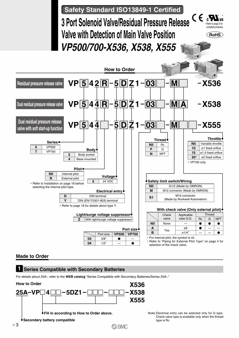
How to Order
Body2 Body ported
4 Base mounted
Voltage5 24 VDC
Light/surge voltage suppressorZ With light/surge voltage suppressor
Series5 VP500
7 VP700
PilotNil Internal pilot
R External pilot
∗ Refer to Installation on page 18 before selecting the internal pilot type.
Electrical entryD DIN terminal
Y DIN (EN175301-803) terminal
∗ Refer to page 18 for details about type Y.
Port sizePort size VP500 VP700
03 3/8" V —
04 1/2" — V
ThreadNil Rc
F G
N NPT
Safety limit switch/WiringNil G1/2 (Made by OMRON)
M M12 connector (Made by OMRON)
S1 M12 connector (Made by Rockwell Automation)
With check valve (Only external pilot)Check valve
Applicable tube O.D.
Thread
Rc G NPT
Nil None — V V V
AYes
ø6 V — —
B ø1/4∗ — — V
∗ For internal pilot, the symbol is nil.∗ Refer to “Piping for External Pilot Type” on page 4 for
selection of the check valve.
ThrottleNil Variable throttle
10 ø1 fixed orifice
15 ø1.5 fixed orifice
20∗ ø2 fixed orifice
∗ VP700 only
3 Port Solenoid Valve/Residual Pressure Release Valve with Detection of Main Valve Position VP500/700-X536, X538, X555
X536X538X555
25A–VP 4 – 5DZ1 – – –
Series Compatible with Secondary Batteries1
Made to Order
For details about 25A-, refer to the WEB catalog “Series Compatible with Secondary Batteries/Series 25A-.”
Secondary battery compatible
Dual residual pressure release valve
Dual residual pressure release valve with soft start-up function
Residual pressure release valve VP
VP
4
4
4
25
5
5
D
D
D
5 ZR
R
M
M
M
1
1
1
A
03
03
03
X536
X538
X555VP
4
4
Z
Z
5
5
How to Order
Note) Electrical entry can be selected only for D type. Check valve type is available only when the thread type is Rc.
Safety Standard ISO13849-1 Certified
Fill in according to How to Order above.
∗ Refer to page 2 for compliant products.
∗
3A

Fluid AirType of actuation N.C. (Spring return)Operation Internal pilot External pilotOperating pressure range 0.25 to 0.7 MPa 0.25 to 0.7 MPaExternal pilot pressure — 0.25 to 0.7 MPa (Same as operating pressure)Maximum operating frequency 30 times/minuteMinimum operating frequency 1 time/weekOperating and ambient temperature −10 to 50°C (No freezing)Ambient humidity 20 to 90%RH (No condensation)Manual override NonePilot exhaust Individual exhaustLubrication Not requiredMounting orientation UnrestrictedImpact/Vibration resistance 150/30 m/s2
Enclosure IP65Operating environment Indoors
B10d (MTTFd calculation)10000000 times (for the safety limit switch made by OMRON) 1000000 times (for the safety limit switch made by Rockwell Automation)
Internal Pilot Type
CautionEven when the inlet pressure is within the op-erating pressure range, restricted piping, etc., may cause reduced flow on the inlet side, leading to the valve not operating properly. Refer to Installation in the Specific Product Precautions for details.
Piping for External Pilot Type
CautionThe product may not operate when the exter-nal pilot pressure is insufficient due to simul-taneous operation or restricted air piping. In this case, use the check valve (AKH series) with the external pilot port, change the piping size or adjust the set pressure to provide a constant pressure of 0.25 MPa or more.
Valve Specifications
SeriesFlow rate characteristics
Weight [g]
1R2 (PRA) 2R3 (ARR)C [dm3/(s·bar)] b Cv C [dm3/(s·bar)] b Cv
VP542-X536 8.9 0.16 2.2 8.9 0.20 2.1 350VP742-X536 15.1 0.21 3.6 15.3 0.22 3.7 590VP544-X538 6.5 0.08 1.3 6.7 0.10 1.3 930VP744-X538 10.3 0.08 2.3 9.7 0.08 2.1 1510VP544-X555 5.2 0.06 1.1 6.7 0.10 1.3 1105VP744-X555 9.8 0.08 2.1 9.7 0.08 2.1 2000
Flow Rate Characteristics / Weight
Electrical entry DIN terminalRated voltage 24 VDCAllowable voltage fluctuation ±10%Power consumption 0.45 WSurge voltage suppressor VaristorIndicator LED
Manufacturer OMRON Rockwell AutomationElectrical wiring G1/2, M12 connector M12 connectorContact resistance 25 mΩ or less 50 mΩ or lessMin. applicable load 5 VDC, 1 mA (Load resistance) 5 VDC, 5 mA (Load resistance)Max. voltage 24 VDCMax. load current 50 mAMax. load inductance 0.5 HInsulation voltage 300 V 600 VProtection against electric shock Class II (EN60947-5-1: 2004)
Solenoid Specifications Safety Limit Switch Specifications
Needle Valve / Flow Rate Characteristics (VP544/744-X555)
600
500
400
300
200
100
00 0.5 1 1.5 2 2.5 3 3.5 4
Number of needle rotations (Turns)
Flo
w r
ate
(L/m
in [A
NR
])
0.25 MPa
0.7 MPa
ø2ø1.5ø1
0.5 MPa
4
Safety Standard ISO13849-1 Certified 3 Port Solenoid Valve/Residual Pressure Release Valve with Detection of Main Valve Position VP500/700-X536, X538, X555
VP
500/
700
X53
6X
538
X55
5V
G34
2X
87Sp
ecific
Prod
uct
Preca
ution
sS
ymb
ols
Sym
bo
lsSp
ecific
Prod
uct
Preca
ution
sOp
tiona
lAc
cess
orie
s
A

3(R)
3(R)
1(P) 1(P) 1(P)
1(P) 1(P) 1(P)
X X
X
3(R)1(P)
2(A)
(31)e
(11)q
r(32)
w(12)
3(R)1(P)
2(A)
(31)e
(11)q
r(32)
w(12)
3(R)1(P)
2(A)
(31)e
(11)q
r(32)
w(12)
3(R)
2(A)
(31)e
(11)q
r(32)
w(12)
(31)e
(11)q
r(32)
w(12)
(31)e
(11)q
r(32)
w(12)
3(R)
2(A)
(31)e
(11)q
r(32)
w(12)
3(R)
2(A)
(31)e
(11)q
r(32)
w(12)
3(R) (31)e
(11)q
r(32)
w(12)
3(R) (31)e
(11)q
r(32)
w(12)
3(R) (31)e
(11)q
r(32)
w(12)
X
2(A)
3(R)
3(R)
(31)e
(11)q
r(32)
w(12)
(31)e
(11)q
r(32)
w(12)
2(A)
3(R)
3(R)
(31)e
(11)q
r(32)
w(12)
(31)e
(11)q
r(32)
w(12)
2(A)
X X
Safety limit switch terminal [N.C.]M12 connector pin numberG1/2 terminal number
Symbols
Terminal/Pin Numbers (Built-in switch 2N.C.)Symbol
VP544(R)/744(R)-X538
VP544(R)/744(R)-X555
M12 connector pin number
Wiring specification
q
w
q
e
r
w
e
r
G1/2terminal number
Wiring specification
(11)
3231
1211(12)
(31)
(32)
VP542(R)/742(R)-X536
Made by OMRON
Safety limit switch
Internal pilot
Internal pilot
Internal pilot
External pilot
External pilot
External pilot
External pilot/With check valve
External pilot/With check valve
External pilot/With check valve
r(32)
w(12)
(31)e
(11)q
5
VP500/700-X536, X538, X555

3(R)
3(R)
wq e
yt r
3(R)1(P)
2(A)
wq e
yt r
3(R)
2(A)
wq e
yt r
3(R)
wq e
yt r
3(R)1(P)
2(A)
wq e
yt r
3(R)1(P)
2(A)
X X
X X
wq e
yt r
3(R)
2(A)
wq e
yt r
3(R)
wq e
yt r
3(R)
2(A)
wq e
yt r
3(R)
wq e
yt r
wq e
yt r
1(P)
1(P) 1(P) 1(P)
2(A)
3(R)
3(R)wq e
yt r
wq e
yt r
1(P)
2(A)
3(R)
3(R)wq e
yt r
wq e
yt r
1(P)
2(A)
XX
Safety limit switch terminal [N.C.]M12 connector pin number
Symbols
VP544(R)/744(R)-X538
VP544(R)/744(R)-X555
Pin Numbers (Built-in switch 3N.C.)
M12 connector pin number
Wiring specification
q
w
q
ey
t
r
t
w
y
e
r
Internal pilot
Internal pilot
Internal pilot
External pilot
External pilot
External pilot
External pilot/With check valve
External pilot/With check valve
External pilot/With check valve
wq e
yt r
VP542(R)/742(R)-X536
Made by Rockwell Automation
Safety limit switch
Symbol
6
Safety Standard ISO13849-1 Certified 3 Port Solenoid Valve/Residual Pressure Release Valve with Detection of Main Valve Position VP500/700-X536, X538, X555
VP
500/
700
X53
6X
538
X55
5V
G34
2X
87Sp
ecific
Prod
uct
Preca
ution
sS
ymb
ols
Sym
bo
lsSp
ecific
Prod
uct
Preca
ution
sOp
tiona
lAc
cess
orie
s

4.5
(25.
7)
A 45
(Max. 10)
26
3.5
732
Port size: 1/8" (Without check valve)Applicable tube O.D.: ø6, ø1/4" (With check valve)(External pilot port)312 x ø4.2
(For mounting)
201.8
118.9
G1/2
(14)202.4
117.423.5
70.8
63.3
31.5
40
4
Applicable cable O.D. ø3.5 to ø7 Safety limit switch (made by OMRON)
Part number: D4N-2B31 (G1/2): D4N-9B31 (M12 connector)
2 x ø4.2(For mounting)
103.454.9
30.7Vent port(ø6.2)
3/8"[1(P), 3(R) port]
22.1
(31.5)(Distance between ports)
3/8"[2(A) port]
(M12 connector)
(22.
9)(W
ith c
heck
val
ve)
4.5
A
(Max. 10)
26
3.5
732
117.754.9
30.7
45
2 x ø4.2(For mounting)
31
216.1
133.2
22.1
25.2
70.8
63.3
31.5
40
4
216.7
131.723.5
8
3/8"[1(P), 3(R) port]
Vent port(ø6.2)
M12 connector
2 x ø4.2(For mounting)
Safety limit switch (made by Rockwell Automation)Part number: 440P-CDPB03R6
(31.5)(Distance between ports)
Applicable cable O.D. ø3.5 to ø7
Port size: 1/8" (Without check valve)Applicable tube O.D.: ø6, ø1/4" (With check valve)(External pilot port)
3/8"[2(A) port]
(22.
9)(W
ith c
heck
val
ve)
Dimensions
VP542(R)-5D Y Z1-03l-l-X536
VP542(R)-5D Y Z1-03l-Ml-X536
VP542(R)-5D Y Z1-03l-S1l-X536
Residual Pressure Release Valve (-X536)
Made by OMRON
Safety limit switch
Made by Rockwell Automation
Safety limit switch
e
q
w
rPin number
View AFor M12 connector
View AM12 connector
r
e
q
w
t
y
Pin number
7
VP500/700-X536

4.5 7.5
44.5
(Max. 10) 224.2
108.4
A
940
63
56.5
224.8
128.931 (14)
9.4
38.588
.8
81.3
107.973.5
42
(34.
7)
G1/2
ø5.2(For mounting)
Applicable cable O.D. ø3.5 to ø7
Vent port(ø6.2)
1/2"[1(P), 3(R) port]
(43)(Distance between ports)
3.5
20.5
ø5.2(For mounting)
333.
5
Port size: 1/8" (Without check valve)Applicable tube O.D.: ø6, ø1/4" (With check valve)(External pilot port)
1/2"[2(A) port]
(22.
9)(W
ith c
heck
val
ve)
(M12 connector)
Safety limit switch (made by OMRON)Part number: D4N-2B31 (G1/2)
: D4N-9B31 (M12 connector)
88.8
81.3
Applicable cable O.D. ø3.5 to ø7
9.4
38.5
33
4.5
(Max. 10)
7.5
2 x ø5.2(For mounting)
41
A 63
56.5
2 x ø5.2(For mounting)
940
73.5
42Vent port(ø6.2)
1/2"[1(P), 3(R) port]
(43)(Distance between ports)
34.2
238.5
143.2
24
8
239.1
143.231
122.2
Port size: 1/8" (Without check valve)Applicable tube O.D.: ø6, ø1/4" (With check valve)(External pilot port)
1/2"[2(A) port]
Safety limit switch (made by Rockwell Automation)Part number: 440P-CDPB03R6
(22.
9)(W
ith c
heck
val
ve)
M12 connector
Dimensions
VP742(R)-5D Y Z1-04l-l-X536
VP742(R)-5D Y Z1-04l-Ml-X536
VP742(R)-5D Y Z1-04l-S1l-X536
Residual Pressure Release Valve (-X536)
View AFor M12 connector
e
q
w
rPin number
View AM12 connector
r
e
q
w
t
y
Pin number
Made by OMRON
Safety limit switch
Made by Rockwell Automation
Safety limit switch
8
Safety Standard ISO13849-1 Certified 3 Port Solenoid Valve/Residual Pressure Release Valve with Detection of Main Valve Position VP500/700-X536
VP
500/
700
X53
6X
538
X55
5V
G34
2X
87Sp
ecific
Prod
uct
Preca
ution
sS
ymb
ols
Sym
bo
lsSp
ecific
Prod
uct
Preca
ution
sOp
tiona
lAc
cess
orie
s

11.3
97.3
18
2933
.5
Applicable cable O.D.ø3.5 to ø7
28.53/8"[2(A) port] 17
.5
91.5
75.5
5472 x ø5.2(For mounting)
(Max. 10)
Channel 2
Channel 1
201.8 (14)
(90.4)34
17.5
57
28.5
79
104.
8
Vent port(ø6.2)
A
112 90.4
62.5
29
17.5
28.2
2 x 3/8"[3(R) port]
(59.7)
G1/2
3/8"[1(P) port]
8
(22.9)(With check valve)
Port size: 1/8" (Without check valve)Applicable tube O.D.: ø6, ø1/4" (With check valve)(External pilot port)
Safety limit switch (made by OMRON)Part number: D4N-2B31 (G1/2)
: D4N-9B31 (M12 connector)
(M12 connector)
Dimensions
VP544(R)-5D Y Z1-03l-l-X538
VP544(R)-5D Y Z1-03l-Ml-X538
Dual Residual Pressure Release Valve (-X538)
View AFor M12 connector
e
q
w
rPin number
Made by OMRON
Safety limit switch
9
VP500/700-X538

11.3
97.3
18
2933
.5
Applicable cable O.D.ø3.5 to ø7
216.1
91.5
75.5
8(104.7)5472 x ø5.2(For mounting)
(Max. 10)
62.5
29
17.5
59.2
28.2
28.53/8"[2(A) port] 17
.5
Channel 2
Channel 1
34
17.5
3/8"[1(P) port]
104.7112
57
28.5
79
104.
8
Vent port(ø6.2)
A
2 x 3/8"[3(R) port]
M12 connector
Port size: 1/8" (Without check valve)Applicable tube O.D.: ø6, ø1/4" (With check valve)(External pilot port)
Safety limit switch (made by Rockwell Automation)Part number: 440P-CDPB03R6
(22.9)(With check valve)
Dimensions
VP544(R)-5D Y Z1-03l-S1l-X538
Dual Residual Pressure Release Valve (-X538)
View AM12 connector
r
e
q
w
t
y
Pin number
Made by Rockwell Automation
Safety limit switch
10
Safety Standard ISO13849-1 Certified 3 Port Solenoid Valve/Residual Pressure Release Valve with Detection of Main Valve Position VP500/700-X538
VP
500/
700
X53
6X
538
X55
5V
G34
2X
87Sp
ecific
Prod
uct
Preca
ution
sS
ymb
ols
Sym
bo
lsSp
ecific
Prod
uct
Preca
ution
sOp
tiona
lAc
cess
orie
s

9.5
(14)(Max. 10)
18
401/2"[2(A) port]
77.5
36
(70.7)
27.2
18
G1/2
2 x 1/2"[3(R) port]
113.
5
94.5
224.2
(88.9)
2 x ø6.2(For mounting)
67 6.5Applicable cable O.D.ø3.5 to ø7
117.3
16
21
41.5
36
99
224.8
88.980
40
(22.9)(With check valve)
124.
8
36
18
1/2"[1(P) port]
A
Vent port(ø6.2)
Channel 2
Channel 1
Port size: 1/8" (Without check valve)Applicable tube O.D.: ø6, ø1/4" (With check valve)(External pilot port)
(M12 connector)
Safety limit switch (made by OMRON)Part number: D4N-2B31 (G1/2)
: D4N-9B31 (M12 connector)
Dimensions
VP744(R)-5D Y Z1-04l-l-X538
VP744(R)-5D Y Z1-04l-Ml-X538
Dual Residual Pressure Release Valve (-X538)
e
q
w
r Pin number
View AFor M12 connector
Made by OMRON
Safety limit switch
11
VP500/700-X538

18
9.5
117.3
16
21
3641
.5
Applicable cable O.D.ø3.5 to ø7
Channel 2
Channel 1 77.5
36
70.2
27.2
18
2 x 1/2"[3(R) port]
113.
5
94.5
8238.5(Max. 10)
(103.2)
6.5672 x ø6.2(For mounting)
1/2"[2(A) port]
40
99
103.2135.9
80
40
1/2"[1(P) port]
36
18
124.
8
(22.9)(With check valve)
Vent port(ø6.2)
A
Port size: 1/8" (Without check valve)Applicable tube O.D.: ø6, ø1/4" (With check valve)(External pilot port)
Safety limit switch (made by Rockwell Automation)Part number: 440P-CDPB03R6
M12 connector
Dimensions
VP744(R)-5D Y Z1-04l-S1l-X538
Dual Residual Pressure Release Valve (-X538)
r
e
q
w
t
y
Pin number
View AM12 connector
Made by Rockwell Automation
Safety limit switch
12
Safety Standard ISO13849-1 Certified 3 Port Solenoid Valve/Residual Pressure Release Valve with Detection of Main Valve Position VP500/700-X538
VP
500/
700
X53
6X
538
X55
5V
G34
2X
87Sp
ecific
Prod
uct
Preca
ution
sS
ymb
ols
Sym
bo
lsSp
ecific
Prod
uct
Preca
ution
sOp
tiona
lAc
cess
orie
s
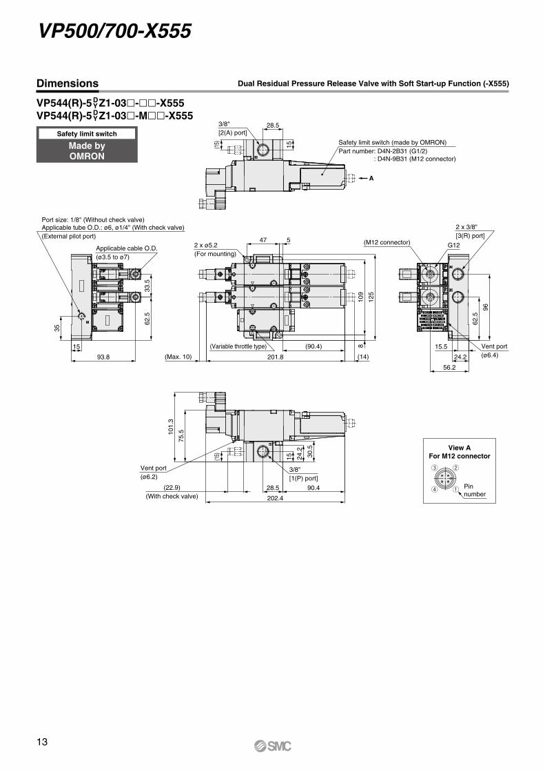
62.5
33.5
Applicable cable O.D.(ø3.5 to ø7)
35
15
93.8
90.428.5(22.9)(With check valve) 202.4
3/8"[1(P) port]
(14)201.8(Max. 10)
(90.4) 8
125
109
547
(Variable throttle type)
75.510
1.3
96
62.5
2 x 3/8"[3(R) port]
G12
56.2
24.2
Vent port(ø6.4)
15.5
15(15)
28.5
30.5
24.2
15(15)
3/8"[2(A) port]
Port size: 1/8" (Without check valve)Applicable tube O.D.: ø6, ø1/4" (With check valve)(External pilot port)
2 x ø5.2(For mounting)
(M12 connector)
Vent port(ø6.2)
A
Safety limit switch (made by OMRON)Part number: D4N-2B31 (G1/2)
: D4N-9B31 (M12 connector)
Dimensions
VP544(R)-5D Y Z1-03l-ll-X555
VP544(R)-5D Y Z1-03l-Mll-X555
Dual Residual Pressure Release Valve with Soft Start-up Function (-X555)
e
q
w
r Pin number
View AFor M12 connector
Made by OMRON
Safety limit switch
13
VP500/700-X555

Vent port(ø6.2)
62.5
33.5
35
8
125
109
75.510
1.3
96
62.5
55.7
24.2
15.5
15
28.5
30.5
24.2
15
(Max. 10)
(22.9)(With check valve)
(15)
3/8"[2(A) port]
Safety limit switch (made by Rockwell Automation)Part number: 440P-CDPB03R6
A
2 x 3/8"[3(R) port]M12 connector
Vent port(ø6.4)
2 x ø5.2(For mounting)
(Variable throttle type)
Applicable cable O.D.(ø3.5 to ø7)
Port size: 1/8" (Without check valve)Applicable tube O.D.: ø6, ø1/4" (With check valve)(External pilot port)
3/8"[1(P) port]
(15)
216.1
(90.4)
893.8
15
90.428.5
216.7
Dimensions
VP544(R)-5D Y Z1-03l-S1ll-X555
Dual Residual Pressure Release Valve with Soft Start-up Function (-X555)
r
e
q
w
t
y
Pin number
View AM12 connector
Made by Rockwell Automation
Safety limit switch
14
Safety Standard ISO13849-1 Certified 3 Port Solenoid Valve/Residual Pressure Release Valve with Detection of Main Valve Position VP500/700-X555
VP
500/
700
X53
6X
538
X55
5V
G34
2X
87Sp
ecific
Prod
uct
Preca
ution
sS
ymb
ols
Sym
bo
lsSp
ecific
Prod
uct
Preca
ution
sOp
tiona
lAc
cess
orie
s
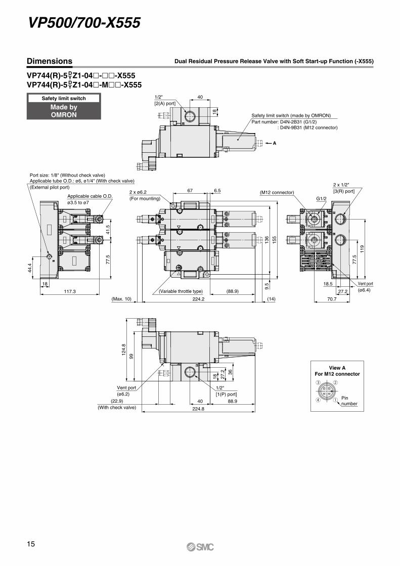
Safety limit switch (made by OMRON)Part number: D4N-2B31 (G1/2)
: D4N-9B31 (M12 connector)
2 x ø6.2(For mounting)Applicable cable O.D.
ø3.5 to ø7
Port size: 1/8" (Without check valve)Applicable tube O.D.: ø6, ø1/4" (With check valve)(External pilot port) 2 x 1/2"
[3(R) port]
G1/2(M12 connector)
A
9.5
155
136
117.3
18
44.4
77.5
41.5
(Max. 10) 224.2
(88.9)
(14)
224.8
88.940
1/2"[1(P) port]
Vent port(ø6.2)
99
124.
8
27.2
18
36
119
77.5
70.7
27.2
6.567
1/2"[2(A) port]
40
18
18.5 Vent port(ø6.4)
(22.9)(With check valve)
(Variable throttle type)
Dimensions Dual Residual Pressure Release Valve with Soft Start-up Function (-X555)
VP744(R)-5D Y Z1-04l-ll-X555
VP744(R)-5D Y Z1-04l-Mll-X555
e
q
w
r Pin number
View AFor M12 connector
Made by OMRON
Safety limit switch
15
VP500/700-X555

2 x ø6.2(For mounting)Applicable cable O.D.
ø3.5 to ø7
Port size: 1/8" (Without check valve)Applicable tube O.D.: ø6, ø1/4" (With check valve)(External pilot port)
117.3
18
44.4
77.5
41.5
1/2"[2(A) port]
40
18 Safety limit switch (made by Rockwell Automation)Part number: 440P-CDPB03R6
9.5
155
136
6.567
(Variable throttle type)
2 x 1/2"[3(R) port]
119
77.5
70.2
27.2
18.5 Vent port(ø6.4)
27.2
18
36
1/2"[1(P) port]
Vent port(ø6.2)
A
(22.9)(With check valve)
(Max. 10) 236.4
(86.3)
8
99
124.
8
245
86.340
M12 connector
Dimensions
VP744(R)-5D Y Z1-04l-S1ll-X555
Dual Residual Pressure Release Valve with Soft Start-up Function (-X555)
r
e
q
w
t
y
Pin number
View AM12 connector
Made by Rockwell Automation
Safety limit switch
16
Safety Standard ISO13849-1 Certified 3 Port Solenoid Valve/Residual Pressure Release Valve with Detection of Main Valve Position VP500/700-X555
VP
500/
700
X53
6X
538
X55
5V
G34
2X
87Sp
ecific
Prod
uct
Preca
ution
sS
ymb
ols
Sym
bo
lsSp
ecific
Prod
uct
Preca
ution
sOp
tiona
lAc
cess
orie
s

B
DA
Center ofF.R.L.body
Port size
BC
A(Spacer width)
FH
GE
E
JK
D
Center ofF.R.L.body
Seal
IN OUT IN OUT
(Max
. 10)
201.
882
.9(1
4)dcba
da b c
(14)
201.
8(M
ax. 1
0)
82.9
VP500/700-X538, X555Optional Accessories
A piping adapter allows installation/removal of the component without removing the piping and thus makes maintenance easier.
Note) l in part numbers indicates a pipe thread type. No indication is necessary for Rc; however, indicate N for NPT, and F for G.
∗ Separate interfaces are required for modular unit.
Piping Adapter: 3/8, 1/2
Part no. Note) Port size A B DE300-l03-A 3/8 31.8 30 30E400-l04-A 1/2 31.8 36 36
Spacer with Bracket
Spacer with Bracket Mounting Position
Part no. A B C D E F G H J KY300T-A 4.2 82 41 71.5 35 14 7 19 4 41Y400T-A 5.2 96 48 86.1 40 18 9 26 5 50
Spacer with bracket
Piping adapter
Dual residual pressure release valve with soft start-up function
Model a b c d Note
VP544-5DZ1-03-X538 33.9 57.2 95.7 220.7AW30-03G-A
Y300T-AE300-03-A
VP744-5DZ1-04-X538 34.4 75.2 118.7 262.7AW40-04G-A
Y400T-AE400-04-A
Model a b c d Note
VP544-5DZ1-03-X555 33.9 57.2 129.2 254.2AW30-03G-A
Y300T-AE300-03-A
VP744-5DZ1-04-X555 34.4 75.2 160.2 304.2AW40-04G-A
Y400T-AE400-04-A
Dual residual pressure release valve (-X538) Dual residual pressure release valve with soft start-up function (-X555)
∗ Each product is not assembled.
VP544-5DZ1-03-X538 ······· 1 pc.
Filter regulatorAW30-03G-A ····················· 1 pc.
Spacer with bracketY300T-A ···························· 3 pcs.
Piping adapterE300-03-A ························· 2 pcs.
Ordering Example∗
For details about optional accessories, refer to the WEB catalog.
17

VP500/700-X536, X538, X555Specific Product PrecautionsBe sure to read this before handling. Refer to the back cover for Safety Instructions. For 3/4/5 Port Solenoid Valve Precautions, refer to “Handling Precautions for SMC Products” and the Operation Manual on the SMC website, http://www.smcworld.com
How to Use DIN Terminal Connector
CautionConnection1. Loosen the holding screw and pull the connector out of the
solenoid valve terminal block.2. After removing the holding screw, insert a flat blade
screwdriver etc. into the notch on the bottom of the terminal block and pry it open, separating the terminal block and the housing.
3. Loosen the screw (slotted screws) in the terminal block. Insert the lead core wires to the terminals according to the connection method, and secure the wires by re-tightening the terminal screw.
4. Secure the cord by fastening the ground nut.
CautionWhen making connections, please note that using other than the supported size (ø3.5 to ø7) heavy-duty cord will not satisfy IP65 (enclosure) standards. Also, be sure to tighten the ground nut and holding screw within their specified torque ranges.
Changing the entry directionAfter separating the terminal block and housing, the cord entry can be changed by attaching the housing in the desired direction (4 directions at 90° intervals).* When equipped with a light, be careful not to damage the light
with the cord’s lead wires.
PrecautionsPlug in and pull out the connector vertically without tilting to one side.
Compatible cableCord O.D.: ø3.5 to ø7(Reference) 0.5 mm2, 2-core or 3-core, equivalent to JIS C 3306
Type “Y”DIN connector type Y is a DIN connector that confirms to the DIN pitch 8-mm standard.• D type DIN connector with 9.4 mm pitch between terminals is
not interchangeable.• To distinguish from the D type DIN connector, “N” is listed at the
end of voltage symbol.• Dimensions are completely the same as D type DIN connector.
Voltage symbolType D: 24 V
Type Y: 24 VN
Terminal screw(3 locations)Tightening torque0.2 to 0.25 N·m
Grommet(Rubber)
Washer
Ground nutTightening torque1.65 to 2.5 N·m
Holding screwTightening torque0.4 N·m
Housing
(Position for lightmounting)
Terminal block
Notch
Light/Surge Voltage Suppressor
DIN TerminalWith light (DZ)
(YZ)
Note) Surge voltage suppressor of varistor has residual voltage corresponding to the protective element and rated voltage; therefore, protect the controller side from the surge voltage.
Limit Switch Cable
OMRON or Rockwell Automation M12 connector limit switch ca-ble is available.
M12 Connector Cable (4 Pins) Made by OMRON
M12 Connector Cable (6 Pins) Made by Rockwell Automation
Installation
1. Use the external pilot type when using VP500/700-X536 or X538 with AV series. Install the AV series to the primary side.
2. For the VP500/700-X536 and X538 internal pilot type, even when the inlet pressure is within the operating pressure range, restricted piping, etc., may cause reduced flow on the inlet side, leading to the valve not operating properly.· The recommended piping size is 3/8" for the VP500 and 1/2" for the VP700. Also, use piping with an I.D. of 10 mm or larger for the VP500, and 13 mm or larger for the VP700.
· When selecting a regulator or a filter regulator, use piping larger than the recommended size with sufficient flow rate characteristics.
· For extended piping between the regulator and the valve (inlet piping), keep piping as short as possible (1 m or less).
· For use under conditions other than those listed above, please use the external pilot type.
No.1(–)(+)
No.2(+)(–)
Varistor
LED
Coil
There is no polarity.
Part number Cable length [mm]ZS-37-L 300ZS-37-M 500ZS-37-N 1000ZS-37-P 2000ZS-37-C 5000
Part number Cable length [mm]VP500-231-1 2000
18
VP
500/
700
X53
6X
538
X55
5V
G34
2X
87Sp
ecific
Prod
uct
Preca
ution
sS
ymb
ols
Sym
bo
lsSp
ecific
Prod
uct
Preca
ution
sOp
tiona
lAc
cess
orie
s
A

* Refer to page 2 for compliant products.
*
M X87VG342 5 ZD 06
How to Order
Voltage5 24 VDC
Port size06 3/4"
10 1"
Electrical entryD DIN terminal
Light/surge voltage suppressorZ With light/surge voltage suppressor
Safety limit switch/Wiring
M M12 connector(Made by OMRON)
S1 M12 connector(Made by Rockwell Automation)
ThreadNil Rc
F G
N NPT
3 Port Solenoid Valve/Residual Pressure Release Valve with Detection of Main Valve PositionVG342-X87
Dual residual pressure release valve R
With check valve (Only external pilot)Check valve
Applicable tube O.D.
Thread
Rc G NPT
Nil None — V V V
AYes
ø8 V — —
B ø5/16" — — V
* For internal pilot, the symbol is nil.* Refer to “Piping for External Pilot Type” on page 20 for
selection of the check valve.
25A–VG342 – 5DZ – – M – X87
Series Compatible with Secondary Batteries1
Made to Order
For details about 25A-, refer to the WEB catalog “Series Compatible with Secondary Batteries/Series 25A-.”
Secondary battery compatible
Fill in according to How to Order above.
How to Order
Safety Standard ISO13849-1 Certified
Note) Electrical entry can be selected only for D type. Check valve type is available only when the thread type is Rc.
PilotNil Internal pilot
R External pilot
* Refer to Installation on page 26 before selecting the internal pilot type.
19A
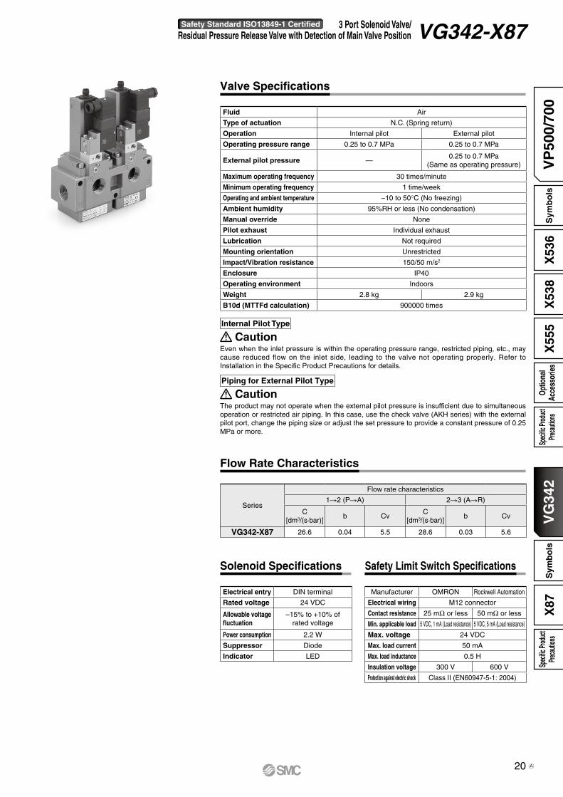
Fluid Air
Type of actuation N.C. (Spring return)
Operation Internal pilot External pilot
Operating pressure range 0.25 to 0.7 MPa 0.25 to 0.7 MPa
External pilot pressure —0.25 to 0.7 MPa
(Same as operating pressure)
Maximum operating frequency 30 times/minute
Minimum operating frequency 1 time/week
Operating and ambient temperature −10 to 50°C (No freezing)
Ambient humidity 95%RH or less (No condensation)
Manual override None
Pilot exhaust Individual exhaust
Lubrication Not required
Mounting orientation Unrestricted
Impact/Vibration resistance 150/50 m/s2
Enclosure IP40
Operating environment Indoors
Weight 2.8 kg 2.9 kg
B10d (MTTFd calculation) 900000 times
Internal Pilot Type
CautionEven when the inlet pressure is within the operating pressure range, restricted piping, etc., may cause reduced flow on the inlet side, leading to the valve not operating properly. Refer to Installation in the Specific Product Precautions for details.
Piping for External Pilot Type
CautionThe product may not operate when the external pilot pressure is insufficient due to simultaneous operation or restricted air piping. In this case, use the check valve (AKH series) with the external pilot port, change the piping size or adjust the set pressure to provide a constant pressure of 0.25 MPa or more.
Valve Specifications
Series
Flow rate characteristics
1R2 (PRA) 2R3 (ARR)
C[dm3/(s·bar)]
b CvC
[dm3/(s·bar)]b Cv
VG342-X87 26.6 0.04 5.5 28.6 0.03 5.6
Flow Rate Characteristics
Electrical entry DIN terminal
Rated voltage 24 VDC
Allowable voltage fluctuation
–15% to +10% of rated voltage
Power consumption 2.2 W
Suppressor Diode
Indicator LED
Solenoid Specifications Safety Limit Switch Specifications
Manufacturer OMRON Rockwell Automation
Electrical wiring M12 connector
Contact resistance 25 mΩ or less 50 mΩ or less
Min. applicable load 5 VDC, 1 mA (Load resistance) 5 VDC, 5 mA (Load resistance)
Max. voltage 24 VDC
Max. load current 50 mA
Max. load inductance 0.5 H
Insulation voltage 300 V 600 V
Protection against electric shock Class II (EN60947-5-1: 2004)
20
Safety Standard ISO13849-1 Certified 3 Port Solenoid Valve/Residual Pressure Release Valve with Detection of Main Valve Position VG342-X87
VP
500/
700
VG
342
X53
6X
538
X55
5X
87Sp
ecific
Prod
uct
Preca
ution
sS
ymb
ols
Sym
bo
lsSp
ecific
Prod
uct
Preca
ution
sOp
tiona
lAc
cess
orie
s
A

wq e
yt r
3(R)
2(A)
wq e
yt r
3(R)
1(P)
wq e
yt r
3(R)
2(A)
wq e
yt r
3(R)
1(P)
wq e
yt r
3(R)
2(A)
wq e
yt r
3(R)
1(P)XX
w
qe
r
3(R)
2(A)
w
qe
r
3(R)
1(P)
w
qe
r
3(R)
2(A)
w
qe
r
3(R)
1(P)
w
qe
r
3(R)
2(A)
w
qe
r
3(R)
1(P)XX
Safety limit switch terminal [N.C.]M12 connector pin number
Symbols
VG342(R)-X87
VG342(R)-X87
Made by OMRON
Safety limit switch
Symbol
Internal pilot
Internal pilot
External pilot
External pilot
External pilot/With check valve
External pilot/With check valve
Pin Numbers (Built-in switch 2N.C.)
M12 connector pin number
Wiring specification
q
w
q
e
r
w
e
r
Symbol Pin Numbers (Built-in switch 3N.C.)
M12 connector pin number
Wiring specification
q
w
q
ey
t
r
t
w
y
e
r
wq e
yt r
w
q e
r
Made by Rockwell Automation
Safety limit switch
21
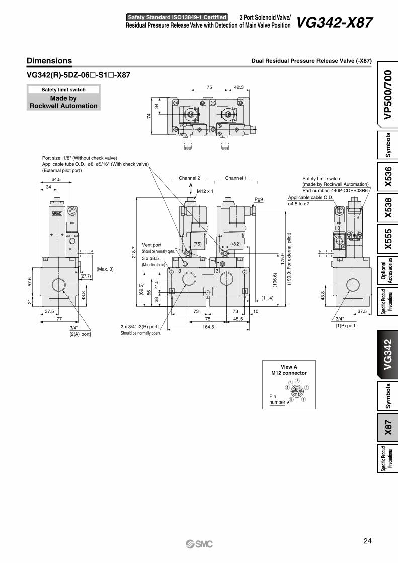
VG342-X87

2
3 3
1
Channel 1
3 x ø8.5(Mounting hole)
Vent portShould be normally open.
2 x 3/4" [3(R) port]Should be normally open.
Applicable cable O.D.ø4.5 to ø7
Safety limit switch (made by OMRON)Part number: D4N-9B31
3/4"[1(P) port]
Channel 2
AM12 x 1
Pg9
Port size: 1/8" (Without check valve)Applicable tube O.D.: ø8, ø5/16" (With check valve)(External pilot port)
(11.4)
175.
9(1
90.9
: For
ext
erna
l pilo
t)
(106
.6)
43.8
37.5
164.5
75 45.5
107373
(48.2)(75)
77
37.5
2157
.6
43.8
(27.7)
(Max. 3)
3/4"[2(A) port]
34
64.5
2841
.5
56(69.
5)
214.
1
42.375
34
74
e
q
w
r Pin number
Dimensions
VG342(R)-5DZ-06l-Ml-X87
View AM12 connector
Dual Residual Pressure Release Valve (-X87)
Made by OMRON
Safety limit switch
22
Safety Standard ISO13849-1 Certified 3 Port Solenoid Valve/Residual Pressure Release Valve with Detection of Main Valve Position VG342-X87
VP
500/
700
VG
342
X53
6X
538
X55
5X
87Sp
ecific
Prod
uct
Preca
ution
sS
ymb
ols
Sym
bo
lsSp
ecific
Prod
uct
Preca
ution
sOp
tiona
lAc
cess
orie
s

2
3 3
1
75.375
34
74
34
64.5
1"[2(A) port]
77
37.5
18.6
43.8
(27.7)
(Max. 3)
230.5
220.5
160.5
75 43.5 30 (5)
387373
28
56(69.
5)
214.
1
Adapter
2 x 1" [3(R) port]Should be normally open.
175.
9(1
90.9
: For
ext
erna
l pilo
t)
(106
.6)
1"[1(P) port]
37.5
43.8
Channel 1Channel 2
30
3 x ø8.5(Mounting hole)
Applicable cable O.D.ø4.5 to ø7
Safety limit switch (made by OMRON)Part number: D4N-9B31
M12 x 1A
Pg9
Vent portShould be normally open.
16.6
(76.2)(75)
Port size: 1/8" (Without check valve)Applicable tube O.D.: ø8, ø5/16" (With check valve)(External pilot port)
41.5
e
q
w
r Pin number
Dimensions
VG342(R)-5DZ-10l-Ml-X87
View AM12 connector
Dual Residual Pressure Release Valve (-X87)
Made by OMRON
Safety limit switch
23
VG342-X87
2
3 3
1
Applicable cable O.D.ø4.5 to ø7
Safety limit switch(made by Rockwell Automation)Part number: 440P-CDPB03R6
Channel 1
3 x ø8.5(Mounting hole)
Vent portShould be normally open.
Channel 2
AM12 x 1
Pg9
Port size: 1/8" (Without check valve)Applicable tube O.D.: ø8, ø5/16" (With check valve)(External pilot port)
(11.4)
(48.2)(75)
3/4"[1(P) port]2 x 3/4" [3(R) port]
Should be normally open.
42.375
34
74
34
64.5
57.6
21
77
37.5
43.8
(27.7)
(Max. 3)
164.5
75 45.5
73 73 10
28
56(69.
5)
218.
7
37.5
43.8
175.
9(1
90.9
: For
ext
erna
l pilo
t)
(106
.6)
3/4"[2(A) port]
41.5
Pin number
r
e
q
w
t
y
Dimensions
VG342(R)-5DZ-06l-S1l-X87
View AM12 connector
Dual Residual Pressure Release Valve (-X87)
Made by Rockwell Automation
Safety limit switch
24
Safety Standard ISO13849-1 Certified 3 Port Solenoid Valve/Residual Pressure Release Valve with Detection of Main Valve Position VG342-X87
VP
500/
700
VG
342
X53
6X
538
X55
5X
87Sp
ecific
Prod
uct
Preca
ution
sS
ymb
ols
Sym
bo
lsSp
ecific
Prod
uct
Preca
ution
sOp
tiona
lAc
cess
orie
s

2
3 3
N1
75.375
34
74
34
64.5
77
37.5
18.6
43.8
(27.7)
(Max. 3)
230.5
220.5
160.5
75 43.5 30 (5)
387373
28
56(69.
5)
218.
7
2 x 1" [3(R) port]Should be normally open.
190.
917
5.9:
For
inte
rnal
pilo
t
(106
.6)
1"[1(P) port]
37.5
43.8
Channel 1Channel 2
30
3 x ø8.5(Mounting hole)
Applicable cable O.D.ø4.5 to ø7
M12 x 1A
Pg9
(76.2)(75)Vent portShould be normally open.
Safety limit switch(made by Rockwell Automation)Part number: 440P-CDPB03R6
(13.4)
Port size: 1/8" (Without check valve)Applicable tube O.D.: ø8, ø5/16" (With check valve)(External pilot port)
41.5
1"[2(A) port]
Pin number
e
q
w
t
yr
Dimensions
VG342(R)-5DZ-10l-S1l-X87
View AM12 connector
Dual Residual Pressure Release Valve (-X87)
Made by Rockwell Automation
Safety limit switch
25
VG342-X87

VG342-X87Specific Product PrecautionsBe sure to read this before handling. Refer to the back cover for Safety Instructions. For 3/4/5 Port Solenoid Valve Precautions, refer to “Handling Precautions for SMC Products” and the Operation Manual on the SMC website, http://www.smcworld.com
Light/Surge Voltage Suppressor
Limit Switch Cable
OMRON or Rockwell Automation M12 connector limit switch ca-ble is available.
M12 Connector Cable (4 Pins) Made by OMRON
M12 Connector Cable (6 Pins) Made by Rockwell Automation
Installation
For the VG342-X87 internal pilot type, even when the inlet pres-sure is within the operating pressure range, restricted piping, etc., may cause reduced flow on the inlet side, leading to the valve not operating properly.· The recommended piping size is 3/4" or larger. Also, use piping with an I.D. of 19 mm or larger.
· When selecting a regulator or a filter regulator, use piping larger than the recommended size with sufficient flow rate characteris-tics.
· For extended piping between the regulator and the valve (inlet piping), keep piping as short as possible (2 m or less).
· For use under conditions other than those listed above, please use the external pilot type.
Part number Cable length [mm]ZS-37-L 300ZS-37-M 500ZS-37-N 1000ZS-37-P 2000ZS-37-C 5000
Part number Cable length [mm]VP500-231-1 2000
Terminal number 2(–)
Coil
Terminal number 1(+)
How to Use DIN Terminal Connector
CautionConnection1. Loosen the holding screw and pull the connector out of the
solenoid valve terminal block.2. After removing the holding screw, insert a flat blade
screwdriver etc. into the notch on the bottom of the terminal block and pry it open, separating the terminal block and the housing.
3. Loosen the screw in the terminal block. Insert the lead core wires to the terminals, and secure the wires by re-tightening the terminal screw.As the product has polarity, referring to the electric circuit diagram, wire the product correctly as per the symbol of the terminal No. of the terminal block.
4. Secure the cord by fastening the ground nut.Tighten the ground nut and holding screw within the specified range of torque.
Changing the entry directionAfter separating the terminal block and housing, the cord entry can be changed by attaching the housing in the opposite direction 180°.* Be careful not to damage the element etc. with the cord’s lead
wires.
PrecautionsPlug in and pull out the connector vertically without tilting to one side.
Compatible cableCord O.D.: ø4.5 to ø7 (Reference) 0.5 to 1.5 mm2, 2-core or 3-core, equivalent to JIS C 3306
Applicable crimped terminalsO-terminals: Equivalent to R1.25-4M defined in the JIS C 2805Y-terminals: Equivalent to 1.25-3L made by J.S.T. Mfg. Co., Ltd.Rod-terminals: Up to size 1.5
Housing
Terminal block
Terminal number
3 locationsTightening torque
0.4 to 0.5 N·m
Terminal screw
Tightening torque0.5 to 0.6 N·m
Holding screw
Grommet(Rubber)
Washer
Tightening torque2.5 to 3.75 N·m
Ground nut
26
VP
500/
700
VG
342
X53
6X
538
X55
5X
87Sp
ecific
Prod
uct
Preca
ution
sS
ymb
ols
Sym
bo
lsSp
ecific
Prod
uct
Preca
ution
sOp
tiona
lAc
cess
orie
s
A

Safety Instructions Be sure to read the “Handling Precautions for SMC Products” (M-E03-3) and “Operation Manual” before use.
CautionSMC products are not intended for use as instruments for legal metrology.Measurement instruments that SMC manufactures or sells have not been qualified by type approval tests relevant to the metrology (measurement) laws of each country. Therefore, SMC products cannot be used for business or certification ordained by the metrology (measurement) laws of each country.
Compliance Requirements
∗1) ISO 4414: Pneumatic fluid power – General rules relating to systems. ISO 4413: Hydraulic fluid power – General rules relating to systems. IEC 60204-1: Safety of machinery – Electrical equipment of machines. (Part 1: General requirements) ISO 10218-1: Manipulating industrial robots – Safety. etc.
Caution indicates a hazard with a low level of risk which, if not avoided, could result in minor or moderate injury.Caution:Warning indicates a hazard with a medium level of risk which, if not avoided, could result in death or serious injury.Warning:
Danger : Danger indicates a hazard with a high level of risk which, if not avoided, will result in death or serious injury.
Warning Caution1. The compatibility of the product is the responsibility of the
person who designs the equipment or decides its specifications.Since the product specified here is used under various operating conditions, its compatibility with specific equipment must be decided by the person who designs the equipment or decides its specifications based on necessary analysis and test results. The expected performance and safety assurance of the equipment will be the responsibility of the person who has determined its compatibility with the product. This person should also continuously review all specifications of the product referring to its latest catalog information, with a view to giving due consideration to any possibility of equipment failure when configuring the equipment.
2. Only personnel with appropriate training should operate machinery and equipment.The product specified here may become unsafe if handled incorrectly. The assembly, operation and maintenance of machines or equipment including our products must be performed by an operator who is appropriately trained and experienced.
3. Do not service or attempt to remove product and machinery/equipment until safety is confirmed.1. The inspection and maintenance of machinery/equipment should only be
performed after measures to prevent falling or runaway of the driven objects have been confirmed.
2. When the product is to be removed, confirm that the safety measures as mentioned above are implemented and the power from any appropriate source is cut, and read and understand the specific product precautions of all relevant products carefully.
3. Before machinery/equipment is restarted, take measures to prevent unexpected operation and malfunction.
4. Contact SMC beforehand and take special consideration of safety measures if the product is to be used in any of the following conditions. 1. Conditions and environments outside of the given specifications, or use
outdoors or in a place exposed to direct sunlight.2. Installation on equipment in conjunction with atomic energy, railways, air
navigation, space, shipping, vehicles, military, medical treatment, combustion and recreation, or equipment in contact with food and beverages, emergency stop circuits, clutch and brake circuits in press applications, safety equipment or other applications unsuitable for the standard specifications described in the product catalog.
3. An application which could have negative effects on people, property, or animals requiring special safety analysis.
4. Use in an interlock circuit, which requires the provision of double interlock for possible failure by using a mechanical protective function, and periodical checks to confirm proper operation.
1. The product is provided for use in manufacturing industries.The product herein described is basically provided for peaceful use in manufacturing industries. If considering using the product in other industries, consult SMC beforehand and exchange specifications or a contract if necessary. If anything is unclear, contact your nearest sales branch.
Limited warranty and Disclaimer/Compliance RequirementsThe product used is subject to the following “Limited warranty and Disclaimer” and “Compliance Requirements”.Read and accept them before using the product.
Limited warranty and Disclaimer1. The warranty period of the product is 1 year in service or 1.5 years after
the product is delivered, whichever is first.∗2)
Also, the product may have specified durability, running distance or replacement parts. Please consult your nearest sales branch.
2. For any failure or damage reported within the warranty period which is clearly our responsibility, a replacement product or necessary parts will be provided. This limited warranty applies only to our product independently, and not to any other damage incurred due to the failure of the product.
3. Prior to using SMC products, please read and understand the warranty terms and disclaimers noted in the specified catalog for the particular products.
∗2) Vacuum pads are excluded from this 1 year warranty.A vacuum pad is a consumable part, so it is warranted for a year after it is delivered. Also, even within the warranty period, the wear of a product due to the use of the vacuum pad or failure due to the deterioration of rubber material are not covered by the limited warranty.
1. The use of SMC products with production equipment for the manufacture of weapons of mass destruction (WMD) or any other weapon is strictly prohibited.
2. The exports of SMC products or technology from one country to another are governed by the relevant security laws and regulations of the countries involved in the transaction. Prior to the shipment of a SMC product to another country, assure that all local rules governing that export are known and followed.
These safety instructions are intended to prevent hazardous situations and/or equipment damage. These instructions indicate the level of potential hazard with the labels of “Caution,” “Warning” or “Danger.” They are all important notes for safety and must be followed in addition to International Standards (ISO/IEC)∗1), and other safety regulations.
Safety Instructions