safety standard for working on gas lines ipss: 1-11-030 …
TRANSCRIPT

INTER PLANT STANDARD – STEEL INDUSTRY
IPSS
SAFETY STANDARD FOR WORKING ON GAS LINES
IN STEEL INDUSTRY
IPSS: 1-11-030-17
Corresponding IS does not exist
0. FOREWORD 0.1 This Inter Plant Standard prepared by Standards Committee on Safety
Appliances and Procedures, IPSS 1:11, with the active participation of the representatives of all the steel plants was adopted in January 2017.
0.2 Objective of this Standard is to describe the recommended basic safety
requirements for working on gas line of BF gas (BFG), CO gas (COG), and LD
gas (LDG) and their mixtures (MG). It describes briefly the precautions to be
taken, safety appliances to be available and their use in gas lines.
1 SCOPE
To describe the recommended basic safety requirements for working on charged/ isolated gas line of BF gas (BFG), CO gas (COG), and LD gas (LDG) and their mixtures (MG). It describes briefly the precautions to be taken and safety appliances available and their use in gas lines.
2 Reference:
This standard establishes the minimum requirement and guidelines for the safe operation while working on gas lines
3 Applicability: Inside & outside Steel Plants
4 Responsibility:
Concerned departments, Agencies

IPSS 1-11-030-17
Page 2 of 18
5 Hazards:
Limit BFG COG LDG MG
Toxicity Highly toxic Toxic Extremely toxic Highly toxic
Flammability Inflammable Inflammable Inflammable Inflammable
Carbon Monoxide %age in volume 23 - 27 6 - 10 60 - 70 10 – 60 Depending on composition
Explosiveness Explosive Explosive Explosive Explosive
Lower Explosive Limit (LEL) 35% in air 6 % in air 15 % in air 10 - 30 % Depending on composition
Higher Explosive Limit (HEL) 73.5% in air
31% in air 72% in air 35 - 70 % Depending on composition
Identification of gases (by smells) Odourless Burning tar Rotten egg
or rotten fish
Odourless Odourless
Table 1 - Hazards of by-product gases
Other hazards include- Falling from height, Nitrogen exposure (barrier of oxygen), Fire and Explosion.
5.1 Effect of Carbon Monoxide on respiratory system:
The carbon monoxide when breath in along with air is absorbed by the blood and deprives the blood of its oxygen carrying capacity and forms carboxy hemoglobin in place of oxyhemoglobin. Hemoglobin has 200 to 300 times more affinity for carbon monoxide than oxygen. The body tissues suffer from anoximia (lack of oxygen).
Symptoms of gas exposure: Headache, Nausea, Vomiting, Feeling of giddiness, difficulty in breathing

IPSS 1-11-030-17
Page 3 of 18
5.2
CO in Blood (%) Effects
0-10 Shortness of breath on exertion
10-20 Increase in shortness in breath and slide headache
20-30 Headache in more pronounced, irritable, judgment impaired, vomiting
30-40 Becomes confused, faint
40-50 Above symptoms are intensified with increased pulse rate respiration
50-60 Unconsciousness
60-70 Respiration may fail, death may occur
Table 2 - Effect of various % of CO in blood
5.3 Fire in gas lines
5.3.1 Fire due to fire source
It needs presence of ignition source in the vicinity from gas cutting welding spatters,
electrical sparking, sparking from tools and tackles, or thunder etc. Standard practices to
be taken for hot work in gas line.
Prevention:
Before commencing and/or executing any work in and around the gas line one should ensure:
a) There should not be any naked power cabling near gas lines.
IPSS 1-11-030-17
Page 4 of 18
b) No leaky flammable gas lines nearby. Inform the owner of the gas lines if any
leakage is found from the pipe, fittings or flanges. Start the job only after the gas
line owner attends the leakage.
c) The tools and tackles to be used for gas line maintenance are non-sparking non-ferrous material.
5.3.2 Fire due to hot work (cutting/welding/grinding/drilling job) near charged gas Line Prevention:
a) Through analysis of the job to address the potential source of fire with meticulous prevention and mitigation plan.
b) Check physically the pipe thickness for before start of welding job on gas line.
c) Check for presence of CO% in the working area / vicinity of job less than equal to 50 ppm.
d) Check for presence of explosive mixture before start of job.
e) Put clay/ POP (plaster of paris) in the joints of all nearby gas line and cover with fireproof ceramic cloth.
f) Gas cutting torch flame should not “hit” the charged gas pipelines.
f) No inflammable material should be present below the working area.
g) Do not use gas pipe/gas pipe supporting structure for earthling the welding m/c. Earthling should be near the welding spot.
h) Continuous CO monitoring should be done throughout the job.
i) Keep ready the fire hose with nozzle at the job point.
j) Keep sufficient nos. of DCP/ CO2 type fire Extinguisher at site (at least 2).
k) If the presumed severity of fire is very high, make the fire tender stationed at the site.
l) During welding on live gas line, % oxygen present in the gas to be monitored on regular basis and should be less than 1%.
m) During the welding on live gas line the current should be kept under control all
the time (70 – 100 amps). Suitable welding rod is to be used and the current
should be adjusted so that the parent metal does not get punctured. The welding
should not be done in continuous run rather it should be staggered.
n) Falling of spatters from height must be prevented.
o) While hot work on gas line, a positive pressure must always be maintained
inside the gas line to prevent entry of atmospheric air. If required, Nitrogen
shrouding at the welding tip must be arranged by providing N2 in hose.
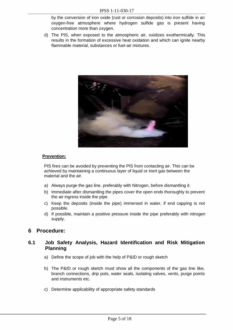
5.3.3 Fire in COG lines even if there is no hot work
a) At times, we experience spontaneous ignition (in the form of white smoke or fire
of Coke Oven Gas (COG) deposits either on the ground or inside the pipe laid
overhead.
b) Most commonly, this occurs during shutdowns when COG pipelines are opened for inspection or maintenance.
c) This happens due to presence of pyrophoric iron sulfide (PIS), which is formed
IPSS 1-11-030-17
Page 5 of 18
by the conversion of iron oxide (rust or corrosion deposits) into iron sulfide in an
oxygen-free atmosphere where hydrogen sulfide gas is present having
concentration more than oxygen.
d) The PIS, when exposed to the atmospheric air, oxidizes exothermically. This
results in the formation of excessive heat oxidation and which can ignite nearby
flammable material, substances or fuel-air mixtures.
Prevention: PIS fires can be avoided by preventing the PIS from contacting air. This can be achieved by maintaining a continuous layer of liquid or inert gas between the material and the air.
a) Always purge the gas line, preferably with Nitrogen, before dismantling it.
b) Immediate after dismantling the pipes cover the open ends thoroughly to prevent
the air ingress inside the pipe.
c) Keep the deposits (inside the pipe) immersed in water, if end capping is not possible.
d) If possible, maintain a positive pressure inside the pipe preferably with nitrogen supply.
6 Procedure:
6.1 Job Safety Analysis, Hazard Identification and Risk Mitigation Planning
a) Define the scope of job with the help of P&ID or rough sketch
b) The P&ID or rough sketch must show all the components of the gas line like,
branch connections, drip pots, water seals, isolating valves, vents, purge points
and instruments etc.
c) Determine applicability of appropriate safety standards
IPSS 1-11-030-17
Page 6 of 18
d) List down the requirements of the applicable safety standards
e) List down the hazards related to job
f) Carry out the site survey and identify site specific hazards
g) Assess the load of pipe, considering the muck inside the pipe, for proper selection of suitable crane.
h) Determine the positioning of crane with the consultation of crane operator & the area owner.
i) Barricading of the work site (if possible)
j) Determine the counter measures to safeguard the workmen and the property damage against the identified hazards (Job specific as well as site specific) . HIRA to be prepared.
6.2 Preparation of check list based SOP: SOP to be made in details considering the following points:
a) Sequence of activities
b) Isolation of pipe segment to be replaced with layout diagram
c) Gas isolation document and positive isolation process
d) Monitoring (preferably with the manometers) and controlling the line pressure during purging.
e) Prepare the checklist as per Annexure 1: Check List based Execution
f) Proper protocol to be made before execution of the job.
6.3 Training and Communication
a) All the persons working near or on the gas line must undergo General safety training and gas safety training conducted by Safety department.
b) A competent person of the department must explain the hazards and risk associated with the job (and site) to the Working agency supervisors through SOP.
c) Working agency supervisor will explain the similar thing to all their workmen before starting the job on daily basis.
d) Line Manager will hold the communication cum review meeting, preferably a day
before the job execution, to communicate vital safety related points to all the
Working agency employees and review the preparation for job execution.
e) Line manager will hold the tool box meeting before starting the job.
6.4 Work permits and necessary clearances
a) Job shall only be start after getting all the clearances and work permits.
b) The executing agency shall issue the written gas clearance as per protocol
c) Area clearance shall be given by the area owner as per protocol
6.5 Isolation of gas mains
IPSS 1-11-030-17
Page 7 of 18
6.5.1 Means of Isolation
a) Water Seal (U Seal/ Quick Dump Seal
b) Blanking
c) Goggle Valves (GV)
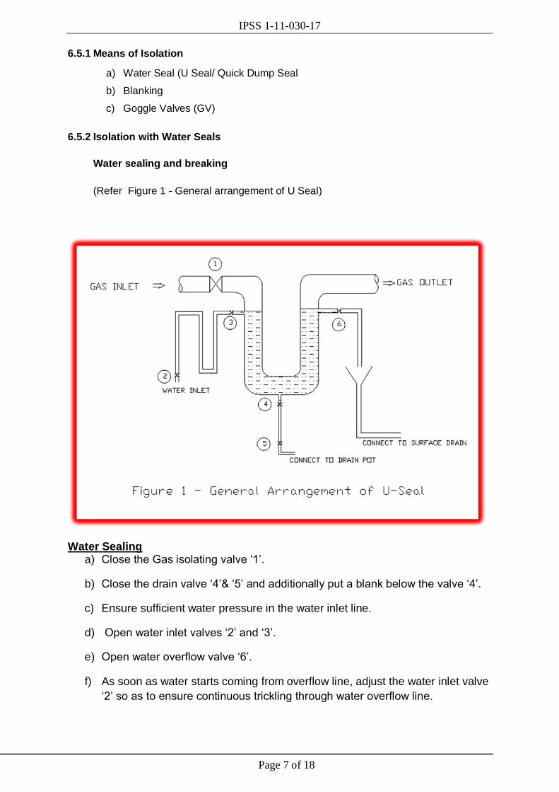
6.5.2 Isolation with Water Seals
Water sealing and breaking
(Refer Figure 1 - General arrangement of U Seal)
Water Sealing a) Close the Gas isolating valve ‘1’.
b) Close the drain valve ‘4’& ‘5’ and additionally put a blank below the valve ‘4’.
c) Ensure sufficient water pressure in the water inlet line.
d) Open water inlet valves ‘2’ and ‘3’.
e) Open water overflow valve ‘6’.
f) As soon as water starts coming from overflow line, adjust the water inlet valve
‘2’ so as to ensure continuous trickling through water overflow line.

IPSS 1-11-030-17
Page 8 of 18
g) Water sealing of U-seal is now complete.
h) Watch from time to time the flow of water trickling from overflow line.
Water Seal Breaking (after necessary purging of gas line) a) Close the water inlet valves ‘2’ and ‘3’.
b) As soon as water trickling from overflow line stops, close the overflow valve ‘6’.
c) Remove the blank below drain valve ‘4’and open the drain valve ‘4’& ‘5’.
d) Open the gas isolating valve ‘1’.
e) Water seal breaking is now complete.
6.5.3
Figure 2 - Arrangement showing the blanking of COG main
a) Select an appropriate and safe location for putting the blank in the gas line
preferably with Nitrogen flooding arrangement.
b) Provide standard scaffolding with suitable platform, toe-guard, railing and proper approach
c) Arrange for suitable gas mask / Breathing apparatus (as required) to be kept at
site to meet any emergency situation. For doing any blanking job, blower type
gas mask can be used as per site condition. One CO detector should be kept
near the suction point of the blower during use to ensure that no CO is sucked in
the blower.
d) Arrange for fire brigade to be stationed near the blanking site.
e) Check for any possible presence of ignition source in the vicinity, if there is any, it should be taken care of.

IPSS 1-11-030-17
Page 9 of 18
f) Blank of the right size to be kept ready along with gasket/ceramic rope/ring joint.
g) Close the gas line isolation valve after getting clearance from consumer.
h) Do the water sealing of the respective gas line and depressurize the gas line by opening end bleeder at approachable safe location.
i) Preferably N2 purging of gas line must be done before doing blanking job to evacuate the toxic gas from the line (Follow steps for purging the gas line 6.6 below).
j) Open out the nut-bolts by easing them. Never do gas cutting or chiselling instead use Nut-splitter.
k) Ensure that isolation valves are fully closed, the amount of concentration of gas
leakage if any should be under permissible limit (50ppm). In case the blanking is
being done with gas leakage, it is to be done by using gas mask.
l) All persons engaged for blanking / de-blanking job should wear fire-retardant cloth.
m) Use non-ferrous tools for making gap between the flanges. Hydraulic Flange Spreader may also be used for this purpose.
n) While putting blank, people working in the vicinity should untie their safety belt
and stand away from the flange joint on the scaffolding platform. This is to
ensure that they can flee away in case of any untoward fire.
o) While blanking / de-blanking, plenty of water should be sprayed over the flange joint.
p) After Blank is put inside the flange joint and nut bolt is put, the working people in the vicinity should tie their safety belt to do the further job.
q) Gasket/rope should be put on both side of the blank.
r) Same precautions are to be followed during removing of blank from gas line.
s) Job to be done under and by the knowledgeable persons and supervisor.
6.5.4 Exemption for the job without blanking
a) Stringent SOP to be made for such job and approval to be taken from Head of the dept. and safety
b) Closing of the Isolating Valve & putting the tags/ locks, and Water sealing shall
be considered as positive isolation with the condition that all the water seals will
be manned (having a suitable means of communication) throughout the job
execution. The deployed person shall ensure:
1) that water is continuously over-flowing from the U-Seal.
2) that make-up water valve for the U-Seal is open

IPSS 1-11-030-17
Page 10 of 18
3) that U-Seal drain valve is closed and locked/ tagged.
c) The blanking of nitrogen purge line and locking of the same after nitrogen
purging is over.
d) If there is no Gas isolation valve before the U-Seal, operation in charge of Gas
pipeline should ensure in writing that the design of U-Seal is such that it will not
blow off in any abnormal condition or present operating condition.
e) The owner of the gas line should ensure that pressure downstream of the U Seal does not affect the overflow of U seal .
6.5.5 Gas main isolation with the help of Goggle Valves Refer SOP on Operation of Goggle Valve. 6.6 Purging of gas line(after positive isolation)
Figure 3: Purging with Nitrogen
a) Close the gas incoming line valve, if provided.
b) Close the outlet gas line valve (consumer’s side), if provided.
c) Do water sealing in incoming line as per 6.5.2 above.
d) Do water sealing in outlet line (consumer side) as per 6.5.2 above.
e) Open the bleeder/ vent valve, just before 1st isolation device (valve or U seal) of
downstream line of all consumers to depressurize the gas line & ensure the line
is completely depressurized before purging preferably with N2.
f) During purging the gas line preferably with nitrogen no person to be allowed to stay near the vicinity of end bleeders as high concentrations of nitrogen will not support life
g) Check and ensure the availability of nitrogen or other inert medium for purging.
h) Open purging valve nearest to the isolation point.
i) Monitor and control the line pressure by installing a manometer in one of the drip
pots. The manometer should not be fixed very near to purge in and vent out

IPSS 1-11-030-17
Page 11 of 18
point to ensure accurate monitoring. Line pressure must be controlled either by
throttling the purge in or vent out valves. Drip pot where manometer is fixed
should not be used as vent out for controlling the line pressure.
j) Continue purging till CO concentration at bleeder becomes less than 50. During checking of CO concentration at bleeder, use suitable gas mask.
k) When CO concentration at bleeder becomes less than 50 ppm, close the N2
purging valve. Purging is now over and gas line job to be carried out from
outside. No man should enter inside the gas line to perform the job.
l) If any job which require entry of man inside the gas line, trapped of the gas line
to be purged out with air (with the help of suitable mechanical means (e.g.
portable compressor or exhaust fan) till O2 comes above 20%. This is applicable
especially for BFG & LDG mains only, as per the requirement of confined space
safety standard.
m) In no case man should enter inside CO gas line. However, for entering CO gas line, separate detailed SOP to be followed.
6.7 Job Execution 6.7.1 General
a) Make a safe approach to working points by scaffolding.
b) Give prior information to all the consumers likely to be affected by the job.
c) On shutdown day take written clearance from all the consumers that they have isolated themselves with the affected mains.
d) Put equipment tags/locks to all the isolating points, including that of consumers.
e) Keep calibrated CO detector with each working group.
f) Use Gas Mask if CO PPM is more than 50 PPM
g) Make adequate area illumination arrangement if job is to be continued after day light or in night
h) Workmen can anchor their safety harness at the working platform as long as hot work is not started. But, before starting any hot work or opening the gas line flanges, the harness should be untied so that workmen can leave the workplace unharmed, in case of any fire.
i) Keep capping arrangement ready at site to cover the open ends of the old pipes (dismantled pipes as well as the pipes left at height at their position).
j) Keep ready the tarpaulin sheet of sufficient size at site to collect the gas line sludge.
k) Care must be taken that gas line effluent and contaminated water does not go into the drain or the soil to prevent ground water and land pollution.
l) Barricade the working area as well as the crane swing area.

IPSS 1-11-030-17
Page 12 of 18
m) Take the road & track clearance if required
n) A display board with emergency contact numbers (such as Fire Brigade, First Aid, Gas Safety, Energy centre, Job In-charge working agency etc.) should be kept at the site.
o) Make rain protection arrangement at the working point if the job is to done in the rainy season or the weather is cloudy and it is likely to be rained.
p) The crane must be positioned on a rigid and levelled surface. If required use rigid wooden blocks and steel plate of sufficient size.
q) If any muck/sludge/effluent is generated during job execution, same has to be collected on the tarpaulin, filled up in the gunny bags and disposed-off suitably.
r) Any steel scrap (old pipes, drip pots, valves, stubs, structural etc.) generated during the job execution should be disposed-off suitably.
s) Clean the area with Water and sweeping, removing all the litters.
6.7.2 Emergency Preparedness:
a) Rescue arrangement to be used whenever anchoring point is possible for using rescue chair. Or, keep scissors’ lift for emergency evacuation.
b) Ensure availability for the rescue arrangement
c) Key persons working on gas line should be trained, shall know how to wear
breathing set and trained on rescue management conducted by Fire Brigade
department.
d) Artificial respirators and gas mask to be kept at site.
e) Proper accessibility and emergency escape route shall be there.
g) If the gas line is likely to catch fire during job execution, keep Fire tenders
stationed at the job site or pre-inform the Fire Brigade department to be ready
for any emergency call. Additionally keep water and Nitrogen hoses at the
working points in ready to use condition.
h) First aid &fire fighting arrangement (water, sand, and clay) should be there and people should know how to use it.
6.7.3 Off line patching/ cladding
a) Isolate and purge the line.
b) Determine the size of plate depending up on the extent of damage and thickness of pipe where welding is to be done.
c) Fix the preformed patch plate and weld it. Avoid continuous run of the weld. (Should be staggered)
d) Soap bubble test at working pressure.
e) In case of any leak, depressurize the line and rectify it.

IPSS 1-11-030-17
Page 13 of 18
f) In case of no leak, start post purging and charge the gas line.
6.7.4 Online leakage repair of gas line
(This is an indicative method, however other suitable methods can be adopted)
a) Using gas masks (preferably blower type); clean the affected surface by nonferrous tools (brush, scrapper or sand paper).
b) Plug the hole if leakage is more than pin hole with the help of wooden plug, piece of rubber, waste cloth soaked with cold-weld compound, etc.
c) Apply cold-weld compound all around the plugged hole.
d) Apply some pressure and hold the putty against the hole for some times till it gets cured.
e) Tie ceramic rope over the pipe to hold the cold welding material tightly against the damage portion of the pipe.
f) Apply Plaster of Paris (POP).
g) If the leak is not repairable by plugging the hole, place a piece of rubber sheet
followed by a metallic clamp to arrest the leakage. Apply cold-weld compound all
around the rubber sheet to completely stop the leakage.
h) Check and ensure no leakage from the repair and repeat the above mentioned steps if required.
6.7.5 Replacement of Stubs/ spool piece of Vent valve/ Drain valve
a) Isolate the line and purge the line.
b) Maintain a positive pressure in the gas line by throttling the purge medium.
c) Gas cut the defective stub piece.
d) Fix stub piece and weld it.
e) Fix up the valve.
f) Soap bubbles test the weld joints at working pressure.
g) In case of any leak, depressurize the line and rectify it.
h) In case of no leak, proceed for gas charging in the line.
6.7.6 Inside cleaning of gas line
a) Isolate the line either by operating the Goggle Valve or putting a blank at suitable
location. THIS JOB SHOULD NOT BE DONE ONLY ON WATER SEAL ISOLATION.
b) Purge the line preferably with N2 till CO ppm becomes nil.
c) Purge the line with Air till O2 becomes >20%
IPSS 1-11-030-17
Page 14 of 18
d) Open the manhole cover or cut an opening in the pipeline at a suitable location for entry & exit of workmen.
e) Take confined space clearance as per protocol.
f) Issue work permit for the workmen to carry out the job inside the gas line.
g) Depute one SAFETY PERSON with Safety Register, who is solely responsible for monitoring and recording of:
1. O2 concentration, in %, inside the pipe, checked periodically.
2. Entry and exit time of each person going inside the pipe. No person should be allowed to work more than 30 min. inside the confined space.
3. Communicating continuously with the persons inside the confined space.
h) Clean the pipe manually or with the help of water jet.
i) Hot work inside the pipe is not allowed.
j) After the job is over, close the manhole cover or patch weld the opening.
k) Soap bubble test at working pressure.
l) In case of any leak, depressurize the line and rectify it.
m) In case of no leak, proceed for gas charging in the line.
6.7.7 In-situ Maintenance of valve (Goggle Valves, shut-off valves, control valves)
a) Isolate & purge the line and put blank on both side of the valve.
b) Purge the bonnet and body of the valve till CO at vent becomes nil.
c) Isolate the energy sources as per positive isolation procedure.
d) Carry out the maintenance job as per SMP guidelines.
e) Once the job is over revert back following above-mentioned steps in reverse order.
f) Leak test all the joints at working pressure and rectify the defect, if found any.
g) Charge the line.
6.7.8 Pipe Replacement
a) Ease out flange bolt one day before to reduce shutdown duration.
b) Isolate and purge the line.
c) Position the crane appropriately.
IPSS 1-11-030-17
Page 15 of 18
d) Loosen and take out alternate flange bolts during crane placement.
e) Hold the pipe with the help of crane and take out remaining flange bolts.
f) Dismantle the pipe, cap the open ends and keep it on the pre-decided location on the ground.
g) Lift the new fabricated pipe with the help of crane and position it between the flanges.
h) Rest the pipe on saddle after matching the hole of flange
i) Insert the flange bolts.
j) Insert the sealing rope / gasket and tighten the fasteners with hand.
k) Tighten the fasteners with suitable torque wrench (Hydraulic / pneumatic / manual) in star pattern up to 50% of torque setting.
l) Torque the fasteners in star pattern, starting 1800 opposite to that followed in step k)
above up to 75% of torque setting.
m) Now torque the fasteners up to 100 % setting in star pattern that followed in step k above.
n) Retighten the fasteners in clockwise direction till 100% uniform torqueing of all the fasteners is achieved.
o) Leak test, post purge and charge the line.
6.7.9 Cleaning of Gas line without lowering
a) Isolate the line.
b) Make a suitable “water filling and quick draining” arrangement and fix up it directly either with drip pot drain pipe or down comer pipe.
c) Fix up a fire hose, connected with HP water system like fire hydrant, fire tender or HP water jetting m/c.
d) Fill the water in the gas line through drip pot and drain through adjacent drip pot, vent, and fittings or through the specially made arrangement.
e) Continue till clean water starts coming out from the outlets.
f) Charge the line.
6.7.10 Cleaning of Gas line after lowering the pipe
For cleaning the pipe by lowering it follow the steps explained in 6.7.8 above
6.7.11 Drip pot root valve poking online
a) Ease out the valve before poking activity.
IPSS 1-11-030-17
Page 16 of 18
b) Close the root valve and disconnect the down comer pipe.
c) Open the root valve, wearing suitable gas mask.
d) Ensure the gas line is not in negative pressure (suction or vacuum).Maintain a positive pressure inside the pipe preferably by injecting nitrogen.
e) Poke the root valve with the help of long wooden stick or non-metallic rod.
f) Once all deposit material (Muck) gets clear, close the valve & connect the down comer pipe.
6.8 Charging of gas lines
a) Once the job is over, get back all the work permits from the working agencies.
b) Pressurize the line preferably with Nitrogen to the working pressure. Pressure can be controlled by throttling Purge In valve, Vent or the drip pot drain valve.
c) Ask the working agencies to check all the points, with the help of soap solution to ensure leak-proof joints.
d) Hammer the weld joints with wooden mallets to remove any weld slag and expose the weld defects.
e) If any defect is found, depressurize the line and rectify the defect.
f) Repeat the process till no defect is observed.
g) Reduce the pressure to by throttling the Purge In valve, Vent or the drip pot drain valve.
h) Keep on monitoring the O2 at the vent near isolation point. When O2 reaches at <1 %, break the water seal from the other extreme end.
i) Close the Purging valve.
j) Keep on monitoring the presence of gas with the help of CO detector at the
vent near isolation point, wearing suitable gas mask. As soon as the CO
reaches at 1000 ppm, close the vent.
k) Inform Energy Centre and return the clearance to all the consumers, asking them to charge the gas in their system.
8 Annexure 1: Check List based Execution 8.1 PPEs
PE People are wearing “comfort fit” clothes (i.e. no loose cloths).
People are wearing cotton clothes.
People are wearing fire retardant jacket while working near or on gas line.
People are with good conditioned safety shoes, Safety glass. helmet with chinstraps

IPSS 1-11-030-17
Page 17 of 18
hand gloves & SIN guards
Gas Cutters are equipped with good conditioned long hand gloves.
Welders are equipped with good conditioned insulated hand gloves.
Welders are equipped with “hands-free” good conditioned welding screens.
Gas Cutters are equipped with good condition cutting goggles.
Welders / Gas Cutters are equipped with fire resistant aprons
People are with calibrated Gas detectors.
Gas detectors are tested by Bump test before usage.
Artificial Respirators is made readily available at site. Artificial Respirators is must wherever gas clearance is required.
Artificial Respirators must be full of oxygen.
People must know how to use Artificial Respirators.
Suitable Gas mask& Breathing Apparatus needs to be used,
8.2 Fire Safety & Process Safety:
Fire extinguisher has been kept at site with valid dates.
People know to operate the fire extinguishers ergonomically.
Fire Hydrant hose pipes have been connected & crack opened for readily usage.
The trial of fire hydrant water pressure to be taken by opening of the valve so that water reaches at the destination.
During Blanking/De-blanking, flange joints or gap at flange joints are being kept wet for elimination of chances of fire.
Anti-spark (non-sparking) tools are to be used for creating gap at flange joints for elimination of chances of FIRE.
Isolate the executing portion of gas lines completely from the process from all ends by putting blanks. So, not only the inlet line, but, the outlet line also needs to be blanked. There are cases where, many blanks are required to isolate completely from the system/process.
During erection / dismantling of Gas pipes, ensure the working pipes as “close ended” as there are potential of fire hazards. Ensure the “deposits/mucks (inside the pipes) wet” by spreading water and then the open ends are needed to be closed 100% to avoid any cross ventilation. One can use non-metals like ceramic clothes or metallic blanks to “eliminate” cross ventilation.
During dismantling of Gas pipes, ensure the dismantled pipes as “close ended” as there are potential of fire hazards. Ensure the “deposits/mucks (inside the pipes) wet” by spreading water and then the open ends are needed to be closed 100% to avoid any cross ventilation.
In the fire prone zone, or where there are every chances of fire, following things are to be done
Keep fire hydrant hoses ready for use.
IPSS 1-11-030-17
Page 18 of 18
Fire extinguishers.
If the presumed severity of fire is very high, make the fire brigade stand at the site.
Isolate the pipeline completely.
An escape route to be ensured
Before this gas cutting, make sure of proper / perfect load distribution for enhancement of the mechanical integrity. As, this water filling will increase the weight.
Proper scaffolding/ working platform to be ensured
Proper barricading of area to be ensured
8.3 Thumb Rules of working at height
People must climb up & down the ladder by using safety belts.
People must tie up all the hand tools & tackles with thin but strong threads to arrest their falling from height during usage.
People must use container to contain the spares, tools & tackles to arrest their falling from height.
The area beneath the working zone must be barricaded to restrict people movement.