safety relays 2010 / 2011 - united automation · 1998 development and at least production of the...
TRANSCRIPT

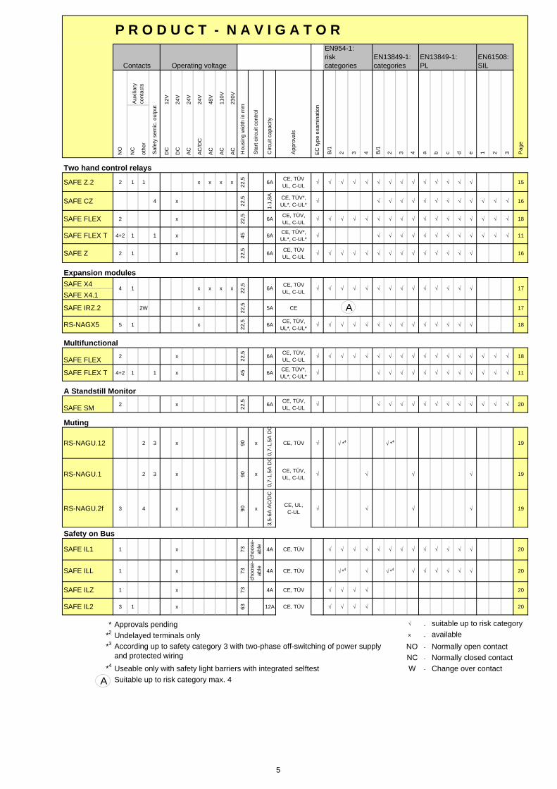
Applications Typ Approvalsn Housing (mm) Category Page
Emergency stop SAFE 4 / 4.1 CE, TÜV, UL, C-UL 22,5 4 6 ..+ safety gate monitoring relays SAFE 5 / 5.1 CE, TÜV, UL, C-UL 22,5 2 / 3 6 SAFE C 1 CE, TÜV, UL, C-UL 22,5 4 7 SAFE FLEX CE, TÜV, UL, C-UL 22,5 4 18 SAFE 1 / 1.1 CE, TÜV, UL, C-UL 22,5 2 / 3 7 SAFE 2 / 2.1 CE, TÜV, UL, C-UL 22,5 4 8 SAFE S.6 CE, TÜV, UL, C-UL 45 4 8 RS-NAGMP / MP.1 CE, TÜV, UL*, C-UL* 100 3 / 4 9 RS-NAGV CE, TÜV, UL, C-UL 100 4 9
..+ time-delay function SAFE T.. CE, TÜV, UL, C-UL 35 4 10 SAFE T ON CE, TÜV, UL, C-UL 35 4 10 SAFE FLEX T CE, TÜV, UL, C-UL 45 11 RS-NAGT / T.1 CE, TÜV, UL, C-UL 45 3 / 4 11
..+ mat-, edges-control relays ** RS-NAGA / AO CE, TÜV, UL, C-UL 45 4 12
SAFE CM CE, TÜV, UL, C-UL 22,5 4 12 SAFE M / M.1 CE, TÜV, UL, C-UL 22,5 3 13
Mat-, edges-control relays **
SAFE 2.2 CE, TÜV, UL, C-UL 22,5 4 13
SAFE L.2 CE, TÜV, UL, C-UL 22,5 4 14 Control devices for safety ligth barriers SAFE CL CE, TÜV , UL, C-UL 22,5 4 14
SAFE FLEX CE, TÜV, UL, C-UL 22,5 4 18 RS-NAGL / L.1 CE, TÜV, UL, C-UL 100 4 15
..+ time-delay function SAFE FLEX T CE, TÜV*, UL*, C-UL* 45 11
Two hand control relays SAFE Z.2 CE, TÜV, UL, C-UL 22,5 4 15 SAFE CZ CE, TÜV , UL, C-UL 22,5 4 16 SAFE FLEX CE, TÜV, UL, C-UL 22,5 4 18 SAFE Z CE, TÜV, UL, C-UL 22,5 4 16
..+ time-delay function SAFE FLEX T CE, TÜV*, UL*, C-UL* 45 11
Expansion modules SAFE X4 / X4.1 CE, TÜV, UL, C-UL 22,5 4 17 SAFE IRZ.2 CE 22,5 17 RS-NAGX 5 CE, TÜV, UL*, C-UL* 22,5 4 18 SAFE IL2 CE, TÜV 63 4 20
Multifunctional SAFE FLEX CE, TÜV, UL, C-UL 22,5 4 18
..+ time-delay function SAFE FLEX T CE, TÜV*, UL*, C-UL* 45 11
A Standstill Monitor SAFE SM CE, TÜV*, UL*, C-UL* 22,5 20
Muting RS-NAGU.12 CE, TÜV 90 2 19 RS-NAGU.1 CE, TÜV, UL, C-UL 90 4 19 RS-NAGU.2f CE, UL, C-UL 90 4 19
Safety on BUS SAFE IL1 / SAFE ILL CE, TÜV / CE, TÜV 73 / 73 4 20 SAFE ILZ / SAFE IL2 CE, TÜV* / CE, TÜV 73 / 63 4 20
* Approvals pending ** Short-circuit-based mats Suitable up to risk category max. 4
Four housing lines - the big diversity at
market
One of the smallest safety relays in the world:
SAFE 1 / 2 / 2.2 / Z
All operating instructions will be found under
www.automation-safety.com
Safety relays 2010 / 2011
A
A

2
About riese electronic: riese electronic gmbh has been founded in 1958. There are working more than 100 employees in Horb a.N. (Baden-Württemberg – head office) and Langenwolschendorf (Thuringia - branch). The divisions consist of the development, production and the Sale of the following product lines: - safety relays (since 1990) - time-, control- and measuring relays - customized development and production of electronic devices and complete products which carry the label/logo of the customer. Company history: 1958 foundation of riese electronic, division of electronic manufacturing services (EMS) 1961 formation of the first freely programmable punching machine of the world 1964 controller for the first electronic ticket machine of the world 1969 removal from Schönaich to Horb a.N. 1979 award from the manager magazine and the Deutsche Bank: "the best innovative middle class company in the year 1979" 1984 former beginning in the SMT Production technology 1987 former beginning of the mass production and of relays 1990 First safety relays 1991 dedication of the subsidiary plant in Zeulenroda-Triebes (Thuringia) 1998 development and at least production of the worldwide smallest safety relays (SAFE 1, SAFE 2, etc.) 2000 smallest two hand control relay in the world (SAFE Z) 2001 realisation and transformation of the largest outsourcing project with more than 300 devices and 3500 components and assemblies 2003 expansion of production, administration and training classroom 2005 expansion of the sales department and warehouse 2006 adjustment of the business in two divisions: 1. EMS (Electronic Manufacturing Service) and 2. Automation & Safety (Components for automation and safety technology) 2008 New building in Langenwolschendorf / Thuringa Since 1995 the quality management system of riese electronic gmbh has been certificated according to ISO 9001. Thus a continuous quality of the products and the services is guaranteed. riese electronic gmbh is one of the pioneers at the safety relay market!
riese – safety relays With a wide product range (currently approx. 40 products) you are on the “safe side” with the newest safety technology from the descendants of “Adam Riese”. Detailed technical datas as well as application examples with detailing of safety categories for safety control devices and muting controller can be found in our application guide. This application guide contains approx. 139 pages with more than 181 different application examples, descriptions and explanations of the most important standards in the safety engineering. Please ask for our application guide on CD-ROM: Phone: 0049 / (0)7451 5501-18 // Fax: 0049 / (0)7451 5501-70 or write us an e-mail to [email protected]. All operating instructions will be found under www.automation-safety.com
Further leaflets for riese electronic
time relays measuring relays
application guide safety relays
(only CD)
Entwicklung und Produktion kundenspezifischer Baugruppen
und Geräte (EMS)
- free of charge - - free of charge - - free of charge - - free of charge -

3
Your personal brandlabel relay Do You would like to have your own label on the safety relay you are using? Do You have certain housing forms which you would like to apply? What we can offer you is a longterm experience due to our customized division. Thus we are able to meet your needs flexibly at any time. Whether there should be "only" Your logo on the relay or also a special colour is demanded we will together work out a complete Brandlabel project plan on which end there is Your specific safety relay - fast and with competence.
Your relay design department Our large relay design team of hard- and software engineers realizes your whishes for new relays. Please ask us for your requirements.
Customized housings: Housing IP 67 applicable to Your relay – pleas ask for it !
choose your individual housing ...
cage clamps, screw clamps, detachable or fixed?
would you like to have a special colour?

12V
24V
24V
24V
48V
110V
230V
NO
NC
othe
r
DC
DC
AC
AC
/DC
AC
AC
AC
SAFE 4 x
SAFE 4.1SAFE 5 x
SAFE 5.1
SAFE C1 4 x 22,5
1-1,
8A CE, TÜVUL, C-UL
√ √ √ √ √ √ √ √ √ √ √ √ √ 7
SAFE FLEX 2 x 22,5 6A CE, TÜV,
UL, C-UL√ √ √ √ √ √ √ √ √ √ √ √ √ √ √ √ √ 18
SAFE 1SAFE 1.1 x
SAFE 2 x
SAFE 2.1
SAFE S.6 2 x x x x x x 45 6A CE, TÜVUL, C-UL
√ √ √ √ √ √ √ √ √ √ √ √ √ √ 8
RS-NAGMPRS-NAGMP.1
RS-NAGV 6 4 x x x x x 100 4A CE, TÜV
UL, C-UL√ √ √ √ √ √ √ √ √ √ √ √ √ √ 9
SAFE T.. 2+2 1 x 35
choo
se-
able 6A
CE, TÜVUL, C-UL √ √ √ √ √ √ √ √ √ √ √ √ √ √ √ √ √ 10
SAFE T ON 2+2 1 x 35 6A CE, TÜVUL, C-UL
√ √ √ √ √ √ √ √ √ √ √ √ √ 10
SAFE FLEX T 4+2 1 1 x 45 6A CE, TÜV*,UL*, C-UL*
√ √ √ √ √ √ √ √ √ √ √ √ √ 11
RS-NAGTRS-NAGT.1
RS-NAGA x
RS-NAGAO
SAFE CM 4 x 22,5
1-1,
8A CE, TÜVUL, C-UL
√ √ √ √ √ √ √ √ √ √ √ √ √ √ √ √ √ 12
SAFE M x
SAFE M.1
SAFE 2.2 2 x 22,5 6A CE, TÜV
UL, C-UL√ √ √ √ √ √ √ √ √ √ √ √ √ √ 13
SAFE L.2 3 x 22,5
choo
se- 6A CE, TÜV
UL, C-UL√ √ *4 √ √ *4 √ √ √ √ √ √ 14
SAFE CL 4 x 22,5
1-1,
8A CE, TÜVUL, C-UL √ √ √ √ √ √ √ √ √ √ √ √ √ 14
SAFE FLEX 2 x 22,5 6A CE, TÜV,
UL, C-UL√ √ √ √ √ √ √ √ √ √ √ √ √ √ √ √ √ 18
SAFE FLEX T 4+2 1 1 x 45 6A CE, TÜV*,UL*, C-UL*
√ √ √ √ √ √ √ √ √ √ √ √ √ 11
RS-NAGL x x x x
RS-NAGL.1
All operating instructions can be found under www.automation-safety.com
Allmost all of our products are certified by:
√
√√
The most devices conformal to RoHS . The exact conversion information (if and when) dates find you in the internet under: www.automation-safety.com/englisch/index.htm
√ √ √ √
√ √
√ √ *2√ √
√√ √ √ √ √√ √ √√√3 1
√ √ √ √√ √ √
√
6A CE, TÜVUL, C-UL
√
x 22,5 5A CE, TÜV
UL, C-UL
x x x 45x x x3 1
√ √ √
√ *2
√
√
√ √ √
√
√ √ √
√
√ √ *26A CE, TÜVUL, C-UL
√ √
5A3 1 x x x
2
13
x 6A
1 x x x x x
5A
√ √ √
√
3
Emergency stop / safety gate monitoring relays with time-delay
x 8A CE, TÜVUL*, C-UL*
√ √ √ √√
Contacts Operating voltage
Hou
sing
wid
th in
mm
Sta
rt ci
rcui
t con
trol
Aux
iliar
yco
ntac
ts
safe
ty s
emic
. out
put
Circ
uit c
apac
ity
App
rova
ls
EN954-1:risk categories
B/1
2 3 4EC
type
exa
min
atio
n
EN13849-1:categories
aB/1
2 c d3 4 3
EN61508:SIL
Pag
e
√ √
e
EN13849-1:PL
1 2b
Emergency stop / safety gate monitoring relays
x √
22,5
CE, TÜVUL, C-UL
√
CE, TÜVUL, C-UL
CE, TÜVUL, C-UL
22,52 x
P R O D U C T - N A V I G A T O R
√ √ √6A CE, TÜVUL, C-UL
√ *3√
22,5
100
4522
,5
x 6A1002 1 1
Clearances for products will be found in the table. A Description of the norms will be found on page 24/25.
√CE, TÜVUL, C-UL √ *4 √√ *4 15
Emergency stop for safety light barriers
√ √ √2+1 11
12
13
Mat-, edges-control relays
Emergency stop / safety gate monitoring relays for function: mat-, edges-control relays
x x x
√ √ √ √ √ √ √ √ √ √ 6
√ √ *3 √ *3 √ *3 √ 6
√
√ *3 7
√ √√ √ √ √ √ √ 8
√ 9√
√
√
√ √
√ √ √ *3
√
√
√
√
√ √ √ √
4
12V
24V
24V
24V
48V
110V
230V
NO
NC
othe
r
DC
DC
AC
AC
/DC
AC
AC
AC
EC
type
exa
min
atio
n
SAFE Z.2 2 1 1 x x x x 22,5 6A CE, TÜV
UL, C-UL√ √ √ √ √ √ √ √ √ √ √ √ √ √ 15
SAFE CZ 4 x 22,5
1-1,
8A CE, TÜV*,UL*, C-UL*
√ √ √ √ √ √ √ √ √ √ √ √ √ 16
SAFE FLEX 2 x 22,5 6A CE, TÜV,
UL, C-UL√ √ √ √ √ √ √ √ √ √ √ √ √ √ √ √ √ 18
SAFE FLEX T 4+2 1 1 x 45 6A CE, TÜV*,UL*, C-UL*
√ √ √ √ √ √ √ √ √ √ √ √ √ 11
SAFE Z 2 1 x 22,5 6A CE, TÜV
UL, C-UL√ √ √ √ √ √ √ √ √ √ √ √ √ √ 16
SAFE X4SAFE X4.1
SAFE IRZ.2 2W x 22,5 5A CE 17
RS-NAGX5 5 1 x 22,5 6A CE, TÜV,
UL*, C-UL*√ √ √ √ √ √ √ √ √ √ √ √ √ √ 18
SAFE FLEX 2 x 22,5 6A CE, TÜV,
UL, C-UL√ √ √ √ √ √ √ √ √ √ √ √ √ √ √ √ √ 18
SAFE FLEX T 4+2 1 1 x 45 6A CE, TÜV*,UL*, C-UL*
√ √ √ √ √ √ √ √ √ √ √ √ √ 11
SAFE SM 2 x 22,5 6A CE, TÜV,
UL, C-UL√ √ √ √ √ √ √ √ √ √ √ √ √ 20
RS-NAGU.12 2 3 x 90 x
0,7-
1,5A
DC
CE, TÜV √ √ *4 √ *4 19
RS-NAGU.1 2 3 x 90 x
0,7-
1,5A
DC
CE, TÜV,UL, C-UL
√ √ √ √ 19
RS-NAGU.2f 3 4 x 90 x
3,5-
6A A
C/D
C
CE, UL, C-UL
√ √ √ √ 19
SAFE IL1 1 x 73
choo
se-
able 4A CE, TÜV √ √ √ √ √ √ √ √ √ √ √ √ √ 20
SAFE ILL 1 x 73
choo
se-
able 4A CE, TÜV √ *4 √ √ *4 √ √ √ √ √ √ 20
SAFE ILZ 1 x 73 4A CE, TÜV √ √ √ √ 20
SAFE IL2 3 1 x 63 12A CE, TÜV √ √ √ √ 20
* Approvals pending √ -
*2 Undelayed terminals only x -
*3-
- Normally closed contact*4 W -
Suitable up to risk category max. 4
17
Useable only with safety light barriers with integrated selftest
x x14
Change over contact
√
Contacts Operating voltage
Hou
sing
wid
th in
mm
Sta
rt ci
rcui
t con
trol
Aux
iliar
yco
ntac
ts
Saf
ety
sem
ic. o
utpu
t
Circ
uit c
apac
ity
App
rova
ls
EN954-1:riskcategories
B/1
2 3 4
EN13849-1:categories
aB/1
2 c d3 4
P R O D U C T - N A V I G A T O R
3
EN61508:SIL
Pag
e
e
EN13849-1:PL
1 2b
suitable up to risk category
Two hand control relays
Safety on Bus
Expansion modules
√ √ √
Muting
Multifunctional
availableNormally open contactNO
NCAccording up to safety category 3 with two-phase off-switching of power supply and protected wiring
CE, TÜVUL, C-UL
x x 22,5 6A
A Standstill Monitor
√√ √ √ √ √ √ √ √ √
A
A
A
5

Emergency stop and safety gate monitoring
l DEVICE SAFE 4 / SAFE 4.1 Emergency stop APPLICATIONS and safety gate monitoring relay APPROVALS CE, TÜV, UL, C-UL CONTACTS 3 normally open safety, 1 normally auxiliary closed LED indicators for status and supply diagnostic SPECIAL CHARACTERISTICS Opposite polarity between channels With (SAFE 4) and without (SAFE 4.1) start control LED Power, channel 1 and channel 2 24 V AC / DC (electronic fuse) OPERATING VOLTAGE 110, 230 V AC (with galvanic disconnection/transformer) POWER CONSUMPTION 24 V AC: ca. 5 VA, 24 V DC: 3 W, 110/230 V AC: 3,7 VA START UP DELAY / FALLBACK TIME < 50 ms / < 30 ms (24 V AC < 50ms) ready after time delay < 0,5 s CONTACT CAPACITY max. 5 A, 240 V AC, 24 V AC / DC CONTACT CAPACITY min. at 24V DC (*) 6 mA SIMULTANEITY ENVIRONMENTAL TEMPERATURE -25°C to + 55°C SWITCHING CAPACITY 1200 VA (resistive load) CONTACT SECURITY normally open 6,3 A quick acting or normally closed 4 A time lag OPERATING MODE (*) We offer all devices who have a CONTACT CAPACITY of min. 100 mA at 24 V DC with hard gold-plated contacts. In this way the CONTACT CAPACITY of min. 100 mA is only 4 mA. Please ask our sales team! CONNECTION DIAGRAM
A supply voltage must be applied to terminals A1 and A2. Power LED illuminates and 24 V DC is available at terminal S11. Terminals S12 and S22 must be connected according to the application example selected to meet the application requirements. To start the unit terminals S33 and S34 must be bridged with a normally open contact. The unit works if you close this contact. At this time the contacts 13-14, 23-24 and 33-34 are closed. The LEDs channel 1 and channel 2 illuminate. In series to this start button an external contactor can be controlled. For version with detachable clamps (screw - or cage clamps) ... please ask our sales team!
S33 S34 S11 S12
Not-HaltE-StopStart
S21S22
FUNCTION CIRCUIT DIAGRAM
control logic~ ~
S21
~~
+=
K1
S11
electronicfuse
A1(+)
A2(-) S34S33
14
K2
K2
3424 42
13
K1
S12 S22 3323 41
Certifications according to Safety relevant substance data Depending on wiring (only max. values are given)
EN ISO 13849-1: PLe, Cat. 4 MTTFd: 154 years / high, DC: 99% / high CCF: achieved

Emergency stop and safety gate monitoring relays DEVICE SAFE 5 / SAFE 5.1 Emergency stop APPLICATIONS and safety gate monitoring relay APPROVALS CE, TÜV, UL, C-UL CONTACTS 2 normally open safety LED indicators for status and supply diagnostic SPECIAL CHARACTERISTICS With (SAFE 5) and without (SAFE 5.1) start control LED Power, channel 1 and channel 2 OPERATING VOLTAGE 24 V AC / DC (electronic fuse) POWER CONSUMPTION ca. 1,6 VA / 1,6 W START UP DELAY / FALLBACK TIME < 50 ms / < 80 ms (AC) , < 50 ms (DC) CONTACT CAPACITY max. 6 A, 250 V AC, 24 V DC CONTACT CAPACITY min. at 24V DC (*) 6 mA SIMULTANEITY ENVIRONMENTAL TEMPERATURE -25°C to + 55°C SWITCHING CAPACITY 1500 VA (resistive load) CONTACT SECURITY 6,3 A quick acting or 4 A time lag OPERATING MODE (*) We offer all devices who have a CONTACT CAPACITY of min. 100 mA at 24 V DC with hard gold-plated contacts. In this way the CONTACT CAPACITY of min. 100 mA is only 4 mA. Please ask our sales team! CONNECTION DIAGRAM
A supply voltage must be applied via emergency stop to terminals A1 and A2. Power LED illuminates if the emergency stop is closed. To start the unit terminals Y2 and Y1 must be bridged with a normally open contact. The unit works if you close this contact. At this time the contacts 13-14, 23-24 are closed. The LEDs channel 1 and channel 2 illuminate. In series to this start button an external contactor can be controlled. For version with detachable clamps (screw - or cage clamps) ... please ask our sales team!
A1 Y1 Y2A2
+24V 0V
Start
FUNCTION CIRCUIT DIAGRAM
-
AC
A1
K1
K2DC+
14 24
controll-logic
A2
electronicfuse
Y2 13 23Y1
Certifications according to Safety relevant substance data Depending on wiring (only max. values are given)
EN ISO 13849-1: PLe, Cat. 3 (***see product-navigator page 4) MTTFd: 71 years / high, DC: 90% / medium CCF: achieved
Not-Halt E-Stop

DEVICE SAFE C1 Safety controller for e-stop APPLICATIONS and gate monitoring applications APPROVALS CE, TÜV, UL, C-UL CONTACTS 4 safety semiconductor outputs LED indicators for status and supply diagnostic SPECIAL CHARACTERISTICS Wearless contacts, "AND", "OR" functions between several SAFE C1 Automatic start possible LED Power, channel 1 and channel 2 + flashing code 24 V DC ( + 25 - 20 % ) OPERATING VOLTAGE Overvoltage protection POWER CONSUMPTION ca. 3 W START UP DELAY / FALLBACK TIME < 70 ms / < 30 ms CONTACT CAPACITY max. total current 1,8 A CONTACT CAPACITY min. at 24V DC (*) infinite SIMULTANEITY no (special variants possible) ENVIRONMENTAL TEMPERATURE -25°C to + 55°C SWITCHING CAPACITY up to 43 W CONTACT SECURITY short circuit proof OPERATING MODE (*) We offer all devices who have a CONTACT CAPACITY of min. 100 mA at 24 V DC with hard gold-plated contacts. In this way the CONTACT CAPACITY of min. 100 mA is only 4 mA. Please ask our sales team! CONNECTION DIAGRAM
2-channel e-stop application with monitoring of reset circuit, opposite channels polarity and contact expansion. The release button must be attached to the e-stop circuits (S11/S12, S21/S22) and the start button must be attached to the reset-circuit (S34/A1). The activation of the semiconductor safety outputs takes place after closing of the reset circuit (pressing the start button). By linkage more SAFE C1 with one another safety applications also complicated, with which different components are to be differently supervised, can be realized. For monitoring of the external contactor, the NC contacts of the force guided contactors must be attached in series to the reset circuit. A1 + 24 V DC A2 0 V DC
S35
S34 S22 S12 S11S21S32
S33 S36 S37 14 34
K1
K2
A2
K1
K2
K1
K2
Not-HaltE-Stop
Start
FUNCTION CIRCUIT DIAGRAM
A1 A2
Power Input circuits
S12 S22 S34 S35 S36
Outputcircuits
Combinationcircuit
S11 S21 S33
MCU1<Controller 1>
MCU2<Controller 2>Sa
fety
out
put c
ircui
ts
14
24
34
44
S32S37
Certifications according to Safety relevant substance data Depending on wiring (only max. values are given)
EN ISO 13849-1/ EN 61508: PLe, Cat. 4 / SIL3 MTTFd: 163 years / high, DC: high, CCF: achieved PFH: 2,87*10-9 1/h, PFD: 2,01*10-6 1/h, SFF: 0,9573

DEVICE SAFE 1 / SAFE 1.1 Emergency stop APPLICATIONS and safety gate monitoring relay APPROVALS CE, TÜV, UL, C-UL CONTACTS 3 normally open safety, 1 normally auxiliary closed LED indicators for status and supply diagnostic SPECIAL CHARACTERISTICS With (SAFE 1.1) and without (SAFE 1) start control LED Power, channel 1 and channel 2 OPERATING VOLTAGE 24 V AC / DC (electronic fuse) POWER CONSUMPTION ca. 2,5 VA / 2,5 W START UP DELAY / FALLBACK TIME < 50 ms / < 100 ms CONTACT CAPACITY max. 5 A, 250 V AC, 24 V DC CONTACT CAPACITY min. at 24V DC (*) 1 mA SIMULTANEITY ENVIRONMENTAL TEMPERATURE -25°C to + 55°C SWITCHING CAPACITY 1250 VA (resistive load) CONTACT SECURITY 6,3 A quick acting or 4 A time lag OPERATING MODE (*) We offer all devices who have a CONTACT CAPACITY of min. 100 mA at 24 V DC with hard gold-plated contacts. In this way the CONTACT CAPACITY of min. 100 mA is only 4 mA. Please ask our sales team! CONNECTION DIAGRAM
A supply voltage must be applied via emergency stop button to terminals A1 and A2. Power LED illuminates if the emergency stop is closed. To start the unit terminals Y2 and Y1 must be bridged with a normally open contact. The unit works if you close this contact. At this time the contacts 13-14, 23-24 and 33-34 are closed, contact 41-42 is opened. The LEDs channel 1 and channel 2 illuminate. In series to this start button an external contactor can be monitored.
A1 Y1 Y2A2
+24V 0V
Not-HaltE-Stop
Start
FUNCTION CIRCUIT DIAGRAM
Überwachungslogik / control logic
~ ~
+
~~
=
K1
elektr.Sicherung /electr. fuse
A1(+)
A2(-) Y1 Y2
14
K2
K2
24 34 42
K1
13 23 33 41
Certifications according to Safety relevant substance data Depending on wiring (only max. values are given)
EN ISO 13849-1: PLd, Cat. 3 (***see product-navigator page 4) MTTFd: 37,57 years / high, DC: 90% / medium, CCF: achieved
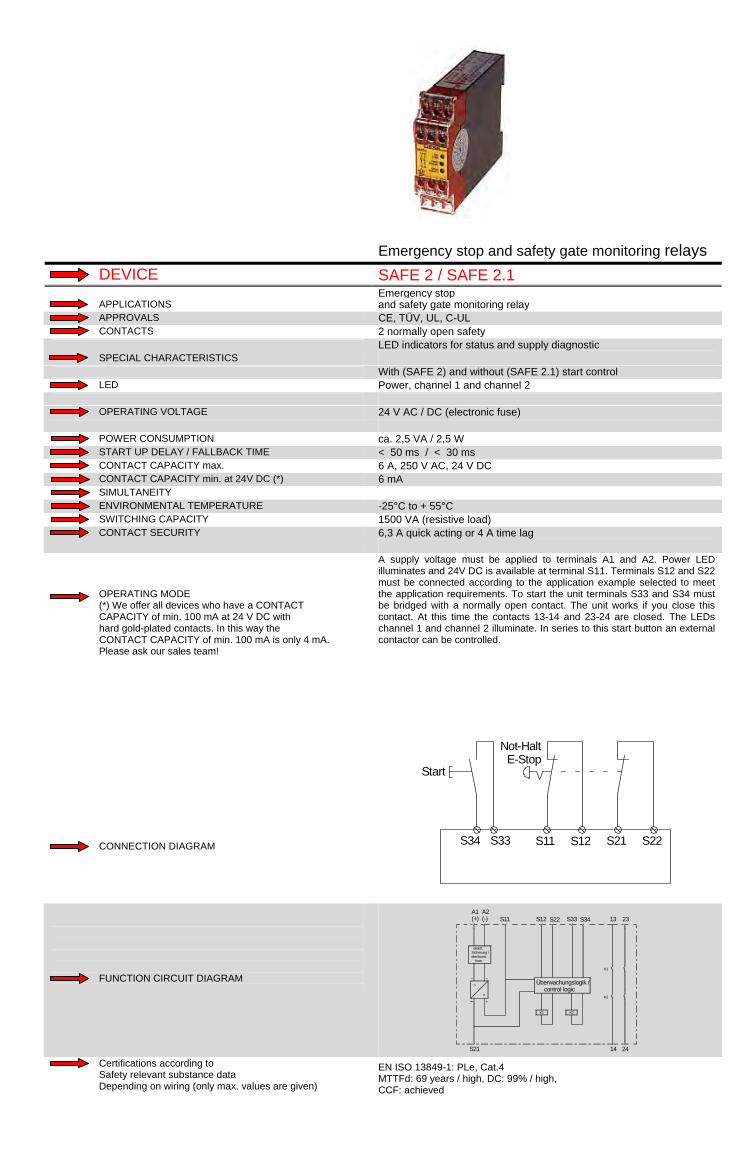
Emergency stop and safety gate monitoring relays DEVICE SAFE 2 / SAFE 2.1 Emergency stop APPLICATIONS and safety gate monitoring relay APPROVALS CE, TÜV, UL, C-UL CONTACTS 2 normally open safety LED indicators for status and supply diagnostic SPECIAL CHARACTERISTICS With (SAFE 2) and without (SAFE 2.1) start control LED Power, channel 1 and channel 2 OPERATING VOLTAGE 24 V AC / DC (electronic fuse) POWER CONSUMPTION ca. 2,5 VA / 2,5 W START UP DELAY / FALLBACK TIME < 50 ms / < 30 ms CONTACT CAPACITY max. 6 A, 250 V AC, 24 V DC CONTACT CAPACITY min. at 24V DC (*) 6 mA SIMULTANEITY ENVIRONMENTAL TEMPERATURE -25°C to + 55°C SWITCHING CAPACITY 1500 VA (resistive load) CONTACT SECURITY 6,3 A quick acting or 4 A time lag OPERATING MODE (*) We offer all devices who have a CONTACT CAPACITY of min. 100 mA at 24 V DC with hard gold-plated contacts. In this way the CONTACT CAPACITY of min. 100 mA is only 4 mA. Please ask our sales team! CONNECTION DIAGRAM
A supply voltage must be applied to terminals A1 and A2. Power LED illuminates and 24V DC is available at terminal S11. Terminals S12 and S22 must be connected according to the application example selected to meet the application requirements. To start the unit terminals S33 and S34 must be bridged with a normally open contact. The unit works if you close this contact. At this time the contacts 13-14 and 23-24 are closed. The LEDs channel 1 and channel 2 illuminate. In series to this start button an external contactor can be controlled.
S34 S33 S11 S12 S21 S22
Not-HaltE-Stop
Start
FUNCTION CIRCUIT DIAGRAM
Überwachungslogik / control logic
~ ~
S21
~~
+=
K1
A1(+)
elektr.Sicherung /electronic fuse
A2(-) S11 S12
14
K2
K2
24
K1
S34S22 S33 13 23
Certifications according to Safety relevant substance data Depending on wiring (only max. values are given)
EN ISO 13849-1: PLe, Cat.4 MTTFd: 69 years / high, DC: 99% / high, CCF: achieved

DEVICE SAFE S.6 Emergency stop APPLICATIONS and safety gate monitoring relay APPROVALS CE, TÜV, UL, C-UL CONTACTS 2 normally open safety LED indicators for status and supply diagnostic SPECIAL CHARACTERISTICS Selectable opposite polarity between channels LED Power, channel 1 and channel 2 24 V AC / DC (without galvanic disconnection, but with a fuse F1) OPERATING VOLTAGE 24 V DC (without galvanic disconnection, but with an electronic fuse) 24, 48, 110-127, 230 V AC (with galvanic disconnection/transformer) POWER CONSUMPTION ca. 3 VA START UP DELAY / FALLBACK TIME < 150 ms / < 30 ms CONTACT CAPACITY max. 6 A, 250 V AC, 24 V DC CONTACT CAPACITY min. at 24V DC (*) 100 mA (*) SIMULTANEITY Simultaneous protective door contacts : ca. 65 ms ENVIRONMENTAL TEMPERATURE -25°C to + 55°C SWITCHING CAPACITY 1380 VA (resistive load) CONTACT SECURITY 6 A quick acting or 4 A time lag OPERATING MODE (*) We offer all devices who have a CONTACT CAPACITY of min. 100 mA at 24 V DC with hard gold-plated contacts. In this way the CONTACT CAPACITY of min. 100 mA is only 4 mA. Please ask our sales team! CONNECTION DIAGRAM
A supply voltage must be applied at terminals A1 and A2 in order to operate the device. If this is done there is a voltage of 24V DC at terminal T11. Terminals T12 and T22 must be wired as shown in the application examples. To start the unit terminal T11 must be bridged with terminal T34 by means of a closing contact or terminal T34 must receive a 24V DC impulse (short time bridging of the connection terminals T11-T34). If this is down contacts 13-14 and 23-24 close. The LEDs channel 1 and channel 2 illuminate. In series with the start button and terminals T11 / T34 the function of an external contactor can be monitored. (*) We offer all devices which have a contact capacity of min. 100mA at 24V DC with hard gold-plated contacts. In this way you get a contact capacity of 4mA.
T34 T33 T11 T12 T22 T44 /PE
Not-HaltE-StopStart
FUNCTION CIRCUIT DIAGRAM
~~
- +=
~ ~
T34A2 (-)A1 (+) T11 T33T12 T22 13 23
K3
K2
K1
F1 T1
K1 K3 K2
2414T44/PE Certifications according to Safety relevant substance data Depending on wiring (only max. values are given)
EN ISO 13849-1: PLd/e, Cat.3 /4 MTTFd: 74,15 years / high, DC: Cat. 3: 90% / medium, Cat. 4: 99% / high CCF: achieved

DEVICE RS-NAGMP / RS-NAGMP.1 Emergency stop APPLICATIONS and safety gate monitoring relay APPROVALS CE, TÜV, (UL, C-UL pending) CONTACTS 3 normally open safety, 1 normally auxiliary closed LED indicators for status and supply diagnostic SPECIAL CHARACTERISTICS With (NAGMP.1) and without (NAGMP) choosable opposite polarity between channels LED Power, Channel 1 and channel 2 24 V AC / DC (without galvanic disconnection, but with a safety OPERATING VOLTAGE 24 VDC / 12VDC (without galvanic disconnection, but with an electronic 24, 110-127, 230 V AC (with galvanic disconnection/transformer) POWER CONSUMPTION ca. 3,5 VA / 24VDC: 1,8W / 12VDC: 1,4W START UP DELAY / FALLBACK TIME < 300 ms / < 20 ms CONTACT CAPACITY max. 8 A, 250 V AC, 250 V DC, normally closed: 24 V AC / DC CONTACT CAPACITY min. at 24V DC (*) 10 mA SIMULTANEITY Simultaneous protective door contacts : ca. 75 ms ENVIRONMENTAL TEMPERATURE - 25°C to + 55°C SWITCHING CAPACITY 2000 VA (resistive load), 200 W CONTACT SECURITY 6 A quick acting or 4 A time lag OPERATING MODE (*) We offer all devices who have a CONTACT CAPACITY of min. 100 mA at 24 V DC with hard gold-plated contacts. In this way the CONTACT CAPACITY of min. 100 mA is only 4 mA. Please ask our sales team! CONNECTION DIAGRAM
A supply voltage must be applied at the terminals A1 and A2 in order to operate the device. If this is done there is a voltage of 24V DC at the terminal T11. Terminals T12, T21, T22 and T23 have to be wired as it is shown in the application examples. To start the unit terminal T33 has to bridged with terminal T34 or terminal T34 has to get a 24V DC impulse (short time bridging of the connection terminals T33-T34). If this is done the safety-contacts 13-14, 23-24 and 33-34 are closed and 41-42 are open. The LEDs channel 1 and channel 2 illuminate. Through terminals X1 and X2 the function of an external contactor can be monitored. Terminals X1 and X2 have to be bridged in order to operate the device.
T21*T33 T34
Not-HaltE-StopStart
* Klemme T21 nur bei RS-NAGMP.1
T12 T22 T11
* terminal T21 only by RS-NAGMP.1
FUNCTION CIRCUIT DIAGRAM
X2
~~
PE
- +=
K1
~~~
R4
~
T1
(+)A1 (-)A2 T34T33T11 X1
14
K2 K3
Controllogic
3424 42
13T12 T22 3323 41T21*
Certifications according to Safety relevant substance data Depending on wiring (only max. values are given)
EN ISO 13849-1: RS-NAGMP: PLd, Cat.3 / RS-NAGMP.1: PLe, Cat.4 MTTFd: 73,61 years / high, DC: Cat. 3: 90% / medium, Cat. 4: 99% / high CCF: achieved
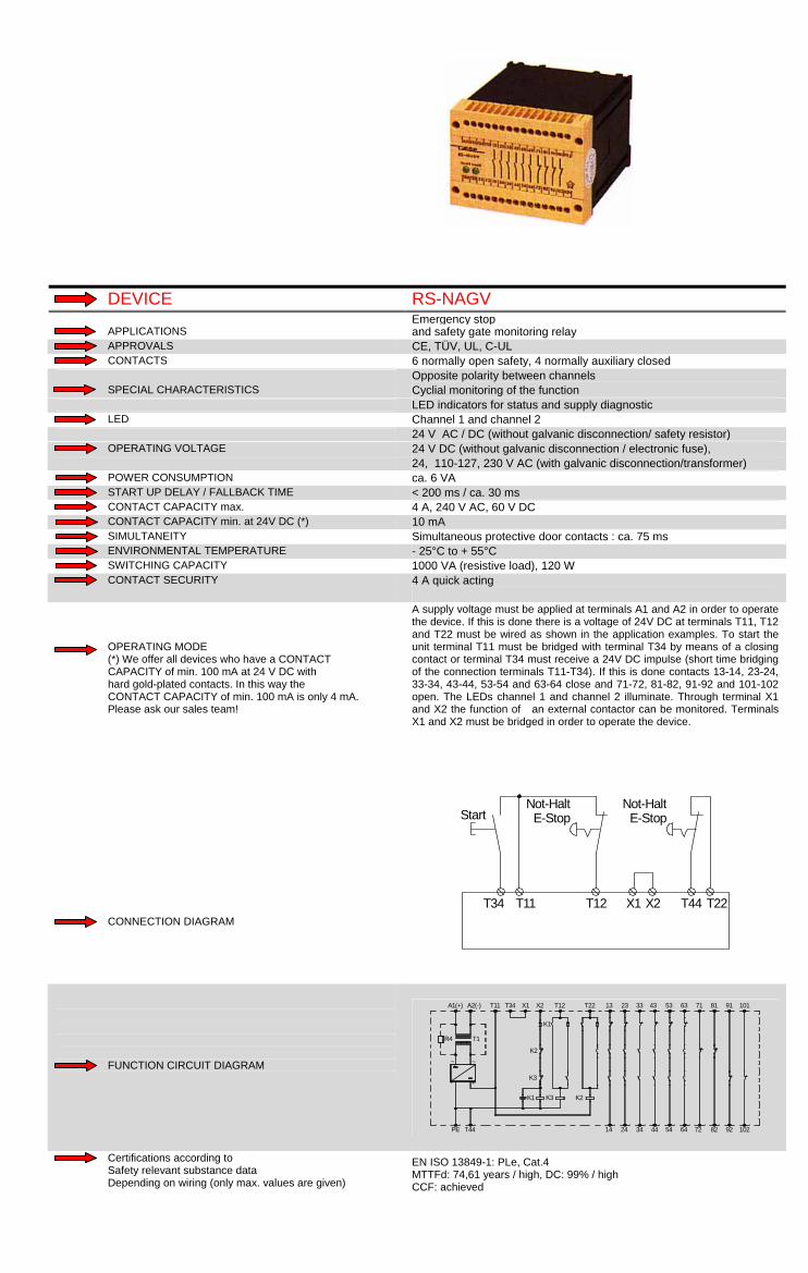
DEVICE RS-NAGV Emergency stop APPLICATIONS and safety gate monitoring relay APPROVALS CE, TÜV, UL, C-UL CONTACTS 6 normally open safety, 4 normally auxiliary closed Opposite polarity between channels SPECIAL CHARACTERISTICS Cyclial monitoring of the function LED indicators for status and supply diagnostic LED Channel 1 and channel 2 24 V AC / DC (without galvanic disconnection/ safety resistor) OPERATING VOLTAGE 24 V DC (without galvanic disconnection / electronic fuse), 24, 110-127, 230 V AC (with galvanic disconnection/transformer) POWER CONSUMPTION ca. 6 VA START UP DELAY / FALLBACK TIME < 200 ms / ca. 30 ms CONTACT CAPACITY max. 4 A, 240 V AC, 60 V DC CONTACT CAPACITY min. at 24V DC (*) 10 mA SIMULTANEITY Simultaneous protective door contacts : ca. 75 ms ENVIRONMENTAL TEMPERATURE - 25°C to + 55°C SWITCHING CAPACITY 1000 VA (resistive load), 120 W CONTACT SECURITY 4 A quick acting OPERATING MODE (*) We offer all devices who have a CONTACT CAPACITY of min. 100 mA at 24 V DC with hard gold-plated contacts. In this way the CONTACT CAPACITY of min. 100 mA is only 4 mA. Please ask our sales team! CONNECTION DIAGRAM
A supply voltage must be applied at terminals A1 and A2 in order to operate the device. If this is done there is a voltage of 24V DC at terminals T11, T12 and T22 must be wired as shown in the application examples. To start the unit terminal T11 must be bridged with terminal T34 by means of a closing contact or terminal T34 must receive a 24V DC impulse (short time bridging of the connection terminals T11-T34). If this is done contacts 13-14, 23-24, 33-34, 43-44, 53-54 and 63-64 close and 71-72, 81-82, 91-92 and 101-102 open. The LEDs channel 1 and channel 2 illuminate. Through terminal X1 and X2 the function of an external contactor can be monitored. Terminals X1 and X2 must be bridged in order to operate the device.
T34 T11
Not-HaltE-StopStart
T12 T44 T22
Not-HaltE-Stop
X1 X2
FUNCTION CIRCUIT DIAGRAM
T44PE
+-
K1
K3
K2K3
~~
T1R4
A2(+)A1 (-)
K1
K2
X2X1T11 T34 T22T12
443414 24 54 64 72 10282 92
43332313 53 63 71 10181 91
Certifications according to Safety relevant substance data Depending on wiring (only max. values are given)
EN ISO 13849-1: PLe, Cat.4 MTTFd: 74,61 years / high, DC: 99% / high CCF: achieved

Emergency stop and safety gate monitoring relays
with time-delay function
DEVICE SAFE T… Emergency stop and safety gate monitoring relay with immediate and APPLICATIONS delayed outputs APPROVALS CE, TÜV, UL, C-UL CONTACTS 2 n.o., 2 n.o. start up delayed, 1 n.c. cross circuit protection or single-channel SPECIAL CHARACTERISTICS Time delay 0,05s - 600s in 64 steps, automatic or manually start with start button LED Power, channel 1, cannel 2, channel 1 and channel 2 time-delayed OPERATING VOLTAGE 24 V AC / DC ( + 25 - 20 % ) (electronic fuse ) POWER CONSUMPTION ca. 4,8 W START UP DELAY / FALLBACK TIME < 400ms / < 30 ms / adjustment CONTACT CAPACITY max. 6 A , 250 V AC, 24 V DC CONTACT CAPACITY min. at 24V DC (*) 6 mA SIMULTANEITY SAFE TN: 1s / SAFE TA,TR: 3s / TU: infinite ENVIRONMENTAL TEMPERATURE - 25°C to + 55°C SWITCHING CAPACITY 1500 VA (resistive load) CONTACT SECURITY 3,6A OPERATING MODE (*) We offer all devices who have a CONTACT CAPACITY of min. 100 mA at 24 V DC with hard gold-plated contacts. In this way the CONTACT CAPACITY of min. 100 mA is only 4 mA. Please ask our sales team! CONNECTION DIAGRAM
When releasing E-Stop button or opening the safety gate (E-Stop circuit are open) the contacts 13-14 and 23-24 (outputs) open. The contacts 47-48/57-58 open delayed at the adjusted time. SAFE TN standby time after applying of the supply voltage < 0,95 s. Opening of the E-Stop circuits meanwhile results to failure. SAFE TA standby time after applying of the supply voltage < 0,95 s. Opening of the E-Stop circuits meanwhile results to several activations of the outputs after the standby time. SAFE TR restart is possible during standby time. SAFE TU standby time after applying of the supply voltage < 0,95 s. Opening of the E-Stop circuits meanwhile results to several activations of the outputs after the standby time.
S33 S34 S11 S12
Not-HaltE-StopStart
S22S21
FUNCTION CIRCUIT DIAGRAM
Power
Logic
A1 S35 S10 S11 S12 13 23 31 47 57
5848322414S22S21S34S33A2
K1
K2
K3
K4
~=
t = 0,05s....600s
Certifications according to Safety relevant substance data Depending on wiring (only max. values are given)
EN ISO 13849-1 / EN 62061: PLe, Cat. 4 / SIL3, SIL CL3 PFH: 3,4*10-9 1/h, PFD: 9,32*10-6 1/h, SFF: 94% MTTFd: >100 years / high, DC: 99% / high, CCF: achieved

DEVICE SAFE T ON Emergency stop and safety gate monitoring relay with immediate and APPLICATIONS delayed outputs APPROVALS CE, TÜV, UL, C-UL CONTACTS 2 n.o., 2 n.o. start up delayed, 1 n.c. cross circuit protection or single-channel SPECIAL CHARACTERISTICS Time delay 0,05s - 600s in 64 steps, automatic or manually start with start button LED Power, channel 1, cannel 2, channel 1 and 2 delayed-on energisation OPERATING VOLTAGE 24 V AC / DC ( + 25 - 20 % ) (electronic fuse ) POWER CONSUMPTION ca. 4,8 W START UP DELAY / FALLBACK TIME 400 ms / 30 ms CONTACT CAPACITY max. 6 A, 250 V AC, 24 V DC CONTACT CAPACITY min. at 24V DC (*) 6 mA SIMULTANEITY no ENVIRONMENTAL TEMPERATURE -25°C to +55°C SWITCHING CAPACITY 1500 VA (ohm load) CONTACT SECURITY 3,6A OPERATING MODE (*) We offer all devices who have a CONTACT CAPACITY of min. 100 mA at 24 V DC with hard gold-plated contacts. In this way the CONTACT CAPACITY of min. 100 mA is only 4 mA. Please ask our sales team! CONNECTION DIAGRAM
If the input circuits S11, S12 and S21, S22 are closed and the start button is released, the safety circuits 13-14, 23-24 will close. By pressing the stop button, the safety circuits 13-14 and 23-24 open. After the set time period has elapsed, the relay K3 and K4 energise. The safety gate switch is released and the safety gate can be opened. By pressing the start button the relay K3 and K4 are energised, K1 and K2 energised and close the safety circuits 13-14 and 23-24.
S21 S22 A2 4847A1 S11 S12 57 58
S10 S33
31
S35 S34
32
13 1423 24
SAFE T ON
START[
SK
ÜK
SK = Sicherheitskreis / Safety circuitÜK = Überwachungskreis / Monitoring circuit
L+
Not-HaltE-Stop Auf
FUNCTION CIRCUIT DIAGRAM
~~ Power
Logic
A1 S35 S10 S11 S12 13 23 31 47 57
5848322414S22S21S34S33A2
K1
K2
K3
K4t = 0,05s....600s
Certifications according to Safety relevant substance data Depending on wiring (only max. values are given)
EN ISO 13849-1 / EN 62061: PLe, Cat. 4 / SIL3, SIL CL3 PFH: 3,4*10-9 1/h, PFD: 9,32*10-6 1/h, SFF: 94% MTTFd: >100 years / high, DC: 99% / high, CCF: achieved

DEVICE RS-NAGT / RS-NAGT.1 Emergency stop and safety gate monitoring relay APPLICATIONS with time-delayed safety output APPROVALS CE, TÜV, UL, C-UL CONTACTS 2 normally open safety, 1 normally open time-delayed safety output Selectable opposite polarity between channels SPECIAL CHARACTERISTICS NAGT : 0,1s - 10s ; NAGT.1 : 0,3 - 30s (ask for the ordering number) Ask for special versions LED Power, channel 1, channel 2 and fault Devices has two voltages : 1 voltage fixed : 24 V DC; OPERATING VOLTAGE Selectable : 24, 110-127 and 230 V AC (with galvanic disconnection/transformer) POWER CONSUMPTION ca. 3 VA START UP DELAY / FALLBACK TIME <150 ms/< 50 ms (undelayed) CONTACT CAPACITY max. 6 A, 250 V AC, 24 V DC CONTACT CAPACITY min. at 24V DC (*) 100 mA (*) SIMULTANEITY Simultaneous protective door contacts : ca.75 ms ENVIRONMENTAL TEMPERATURE - 25°C to + 50°C SWITCHING CAPACITY 1500 VA (resistive load) CONTACT SECURITY 10 A quick acting or 6 A time lag OPERATING MODE (*) We offer all devices who have a CONTACT CAPACITY of min. 100 mA at 24 V DC with hard gold-plated contacts. In this way the CONTACT CAPACITY of min. 100 mA is only 4 mA. Please ask our sales team! CONNECTION DIAGRAM
A supply voltage must be applied to terminals A1 and A2 (for AC supplies) or terminals B1 and B2 (for DC supplies). Once the supply voltage is applied, 24V DC is available at terminal T11; power LED illuminates. Terminals T12, K21 and K22 must be connected according to the application example selected to meet the application requirements. Feedback monitoring of external devices is accomplished by a connection between terminals T34 / X1 and X2. If the application does not require external monitoring, T34 / X1 and X2 must be bridged. To start the unit, terminal T11 and T34 / X1 must be bridged (automatic reset) or a momentary bridging of T11 and T34 / X1 must take place. With all of the above in place safety contacts 13-14, 23-24 and 77-78 close. Channel 1 (K2 energized) and channel 2 (K3 energized) green LEDs illuminate to show channel status. Fault LED illuminates when a short circuit takes place, at the input stage or internally. (*) Special edition with hard gold-plated contacts is also available. Connecting the ground wire to PE - see page 22.
T11 X2
Not-HaltE-Stop Start
T12 K21 K22
B1(+), PE/B2(-) : 24V DC-Anschluss oder A1, A2 : AC-Anschluss
PE/B2
mit Querschlusssicherheitwith opposite polarity between channels
T11
ohne Querschlusssicherheitwithout opposite polarity between channels
PE/B2 T11
T34/X1
Ebene 1Level 1
21
Ebene 2Level 2
Not-HaltE-Stop
2
2
1
1
FUNCTION CIRCUIT DIAGRAM
power onand control
cyclic test
elec
troni
c
= fuse
channel 1
B1(+)
+
PE/B2(-)
- unde-layed
K2 K4layedde-
~
A2
~~~~~
A1
T1
T34/X1T11 T12
channel 2 K3
2414
layedde-
K3layedunde-
K5
78
K5
K4logic,
K2
K22X2 K21 13 23 77
Certifications according to Safety relevant substance data Depending on wiring (only max. values are given)
EN ISO 13849-1: PLe, Cat. 4 / PLd, Cat. 3 (time delayed) MTTFd: 57 years / high, DC: Cat. 3: 90% / medium, Cat.4: 99% / high CCF: achieved

DEVICE SAFE FLEX T (OUTLOOK) Safety controller APPLICATIONS with choosable multi functions and adjustable time delay APPROVALS CE, (TÜV, UL, C-UL pending) CONTACTS 4 normally open (1x basic insulation), 2 normally open time-delayed, SPECIAL CHARACTERISTICS LED indicators for status and supply diagnostic optical failure indication by LEDs , Automatic start possible LED 24 V DC ( + 20 - 25 % ) OPERATING VOLTAGE Overvoltage protection POWER CONSUMPTION START UP DELAY / FALLBACK TIME CONTACT CAPACITY max. CONTACT CAPACITY min. at 24V DC (*) 5 mA SIMULTANEITY depending on the choosen functionality (see technical data) ENVIRONMENTAL TEMPERATURE - 25°C to + 55°C SWITCHING CAPACITY CONTACT SECURITY 6 A quick acting or 4 A time lag OPERATING MODE (*) We offer all devices who have a CONTACT CAPACITY of min. 100 mA at 24 V DC with hard gold-plated contacts. In this way the CONTACT CAPACITY of min. 100 mA is only 4 mA. Please ask our sales team! CONNECTION DIAGRAM
unverzögerteAusgänge / undelayed outputsverzögerteAusgänge / delayedoutputs } }}
= time-delayTdTd <Td Td
S32 S33 S22S12S11 S21S34
A1
Rückführung/feedback control loop
S35 S36 A2
Start
+24V DC 0V DC
FUNCTION CIRCUIT DIAGRAM
S33 S36 S12 S31 13 23
14 24
S11 S21S32S22 S34 S35
INPUT CIRCUIT
Mikrocontroller 1 K1
OUTPUT CIRCUIT
A1
POWER
A2
K2Mikrocontroller 2
K4Mikrocontroller 4
K3Mikrocontroller 3
verz
öger
t / ti
me-
dela
yed
33 43
34 44
51
52
67
68
77
78 Certifications according to Safety relevant substance data Depending on wiring (only max. values are given)

Mat-, edges-control relays DEVICE RS-NAGA / RS-NAGAO Emergency stop and safety gate and mat control relay APPLICATIONS (the device-system isn´t guide positive for the "start" push button) APPROVALS CE, TÜV, UL, C-UL CONTACTS 3 normally open safety, 1 normally auxiliary closed LED indicators for status ans supply diagnostic SPECIAL CHARACTERISTICS Selectable opposite polarity between channels With (RS-NAGA) and without (RS-NAGAO) start control LED Power, channel 1 and channel 2 24 V DC (with electronic fuse) OPERATING VOLTAGE 24, 48, 110-127, 230 V AC (with galvanic disconnection/transformer) 24 V AC / DC (fuse F1) not useable for safety mats POWER CONSUMPTION ca. 3,5 VA, 24 V DC: 2W START UP DELAY / FALLBACK TIME < 150 ms / < 50 ms CONTACT CAPACITY max. 6 A, 250 V AC, 250 V DC CONTACT CAPACITY min. at 24V DC (*) 10 mA SIMULTANEITY Simultaneous protective door contacts : ca.75 ms ENVIRONMENTAL TEMPERATURE - 25°C to + 55°C SWITCHING CAPACITY 1500 VA (resistive load), 100W CONTACT SECURITY 6 A quick acting (normally open), 4 A time lag (normally closed) OPERATING MODE (*) We offer all devices who have a CONTACT CAPACITY of min. 100 mA at 24 V DC with hard gold-plated contacts. In this way the CONTACT CAPACITY of min. 100 mA is only 4 mA. Please ask our sales team! CONNECTION DIAGRAM
A supply voltage must be applied to terminals A1 and A2. Once the supply voltage is applied, 24V DC is available at terminal S11; power LED illuminates. Terminals S12, K12 and X1/S22 must be connected according to the application example selected to meet the application requirements. To start the unit, terminal X2 and X1/S22 must be bridged. At the variation "with reset-monitoring" (RS-NAGA) the relay reacts after removing the bridge X2 to X1/S22. At the variation "without reset-monitoring" (RS-NAGAO) the function starts after bridging X2 and X1/S22. With all of the above in place safety contacts 13-14, 23-24, 33-34 closed and 41-42 open. Channel 1 and channel 2 LEDs illuminate. In series to the reset-button at terminals X2 and X1/S22 an external device can be monitored.
S12
Not-HaltE-Stop
X2 S11 S23X1S22
FUNCTION CIRCUIT DIAGRAM
K1
X2
Überwachunglogikmonitoring logic
+
~
S23
~~=
~
A2
T1
A1
F1
S22S11X1/
14 24
K2
K2
34 42
S12K12 2313
K1
33 41
Certifications according to Safety relevant substance data Depending on wiring (only max. values are given)
EN ISO 13849-1: PLe, Cat. 4 MTTFd: 73,21 years / high, DC: Cat.4: 99% / high CCF: achieved

DEVICE SAFE CM Safety controller for safety mats and safety bars with a maximum APPLICATIONS resistance of 500 ohms APPROVALS CE, TÜV, UL, C-UL CONTACTS 4 safety semiconductor outputs LED indicators for status and supply diagnostic SPECIAL CHARACTERISTICS wearless contacts, "AND" function between several SAFE C possible, automatic start possible LED Power, channel 1 and channel 2 24 V DC ( + 25 - 20 % ) OPERATING VOLTAGE Overvoltage protection POWER CONSUMPTION ca. 3 W START UP DELAY / FALLBACK TIME < 30 ms / < 140ms (single channel < 360 ms) CONTACT CAPACITY max. total current 1,8 A CONTACT CAPACITY min. at 24V DC (*) infinite SIMULTANEITY not necessary ENVIRONMENTAL TEMPERATURE -25°C to + 55°C SWITCHING CAPACITY to 43 W CONTACT SECURITY short circuit proof OPERATING MODE (*) We offer all devices who have a CONTACT CAPACITY of min. 100 mA at 24 V DC with hard gold-plated contacts. In this way the CONTACT CAPACITY of min. 100 mA is only 4 mA. Please ask our sales team! CONNECTION DIAGRAM
4 wire technology with wire break protection or 2 wire technology and terminating resistor with wire break protection are optional. Start monitoring and automatic start are optional. For monitoring of external relays to n.c. contacts are put in series of the start circuit "AND" function among several SAFE C is possible. A1 + 24 V DC A2 0 V DC
S33
S36 S37
14 34
K1
K2
A2
K1
K2
S34
S22S12
S11 S21 S32
8k2
K1
K2
S35
FUNCTION CIRCUIT DIAGRAM
A1 A2
Power Input circuits
S12 S22 S34 S35 S36
Outputcircuits
Combinationcircuit
S11 S21 S33
MCU1<Controller 1>
MCU2<Controller 2>Sa
fety
out
put c
ircui
ts
14
24
34
44
S32S37
Certifications according to Safety relevant substance data Depending on wiring (only max. values are given)
EN ISO 13849-1/ EN 61508: PLe, Cat. 4 / SIL3 MTTFd: 163 years / high, DC: high, CCF: achieved PFH: 2,87*10-9 1/h, PFD: 2,01*10-6 1/h, SFF: 0,9573

DEVICE SAFE M / SAFE M.1 Mat and contact edges control relay with a max. mats-resistance APPLICATIONS of 200 ohms APPROVALS CE, TÜV, UL, C-UL CONTACTS 3 normally open safety, 1 normally auxiliary closed LED indicators for status and supply diagnostic SPECIAL CHARACTERISTICS Opposite polarity between chanels With (SAFE M) and without (SAFE M.1) automatic start LED Power, channel 1 and channel 2 OPERATING VOLTAGE 24 V AC / DC (electronic fuse) SAFE M: 115 V AC (with galvanic disconnection/transformer) POWER CONSUMPTION 24, 115 V AC: ca. 5 VA, 24 V DC: 3 W START UP DELAY / FALLBACK TIME < 50 ms / < 30 ms (24 V AC < 50 ms) CONTACT CAPACITY max. 5 A, 240 V AC, 24 V DC CONTACT CAPACITY min. at 24V DC (*) 6 mA SIMULTANEITY ENVIRONMENTAL TEMPERATURE -25°C to + 55°C SWITCHING CAPACITY 1200 VA (resistive load) CONTACT SECURITY 6,3 A quick acting (normally open) or 4 A time lag (normally closed) OPERATING MODE (*) We offer all devices who have a CONTACT CAPACITY of min. 100 mA at 24 V DC with hard gold-plated contacts. In this way the CONTACT CAPACITY of min. 100 mA is only 4 mA. Please ask our sales team! CONNECTION DIAGRAM
A supply voltage must be applied to terminals A1 and A2. Power LED illuminates and 24V DC is available at terminal S11. Terminals S12 and S22 must be connected according to the application example selected to meet the application requirements. To start the unit terminals S33 and S34 must be bridged with a normally open contact. The unit works if you close this contact. At this time the contacts 13-14, or bridge for automatically start 23-24 and 33-34 are closed. The LEDs channel 1 and channel 2 illuminate. In series to this start button an external contactor can be controlled. For automatic start (SAFE M only) the terminals S33 and S34 must be brigded. The safety mats and safety bars must be of 4 wire technology or 2 wire technology and have to agree to the cross circuit principle. For version with detachable clamps (screw - or cage clamps) ... please ask our sales team!
S33 S11 S21 S12S34
Start
S22
FUNCTION CIRCUIT DIAGRAM
S12
Überwachungslogik /monitoring logic
~ ~~~
+=
K1
elektr. Sicherung electr. fuse Transformator transformer
A1(+)
A2(-) S34S33 S11
14
K2
K2
3424 42
13
K1
S22S21 3323 41
Certifications according to Safety relevant substance data Depending on wiring (only max. values are given)
EN ISO 13849-1: PLe, Cat. 3 MTTFd: 73,21 years / high, DC: 90% / medium, CCF: achieved PFH: 5,81*10-9 1/h, SFF: 99%

DEVICE SAFE 2.2 Mat and contact edges control relay APPLICATIONS APPROVALS CE, TÜV, UL, C-UL CONTACTS 2 normally open safety LED indicators for status and supply diagnostic SPECIAL CHARACTERISTICS Safety category 4, opposite polarity between channels without start control LED Power, channel 1 and channel 2 OPERATING VOLTAGE 24 V AC / DC (electronic fuse) POWER CONSUMPTION ca. 2,5 VA / 2,5 W START UP DELAY / FALLBACK TIME < 50 ms / < 30 ms CONTACT CAPACITY max. 6 A, 250 V AC, 24 V DC CONTACT CAPACITY min. at 24V DC (*) 1 mA SIMULTANEITY Simultaneous protective door contacts : ca.40 ms ENVIRONMENTAL TEMPERATURE -25°C to + 55°C SWITCHING CAPACITY 1500 VA (resistive load) CONTACT SECURITY 6,3 A quick acting or 4 A time lag OPERATING MODE (*) We offer all devices who have a CONTACT CAPACITY of min. 100 mA at 24 V DC with hard gold-plated contacts. In this way the CONTACT CAPACITY of min. 100 mA is only 4 mA. Please ask our sales team! CONNECTION DIAGRAM
A supply voltage must be applied to terminals A1 and A2. Power LED illuminates and 24V DC is available at terminal S11. Terminals S12 and S22 must be connected according to the application example selected to meet the application requirements. To start the unit terminals S33 and S34 must be bridged with a normally open contact. The unit works if you close this contact. At this time the contacts 13-14 and 23-24 are closed. The LEDs channel 1 and channel 2 illuminate. In series to this start button an external contactor can be controlled. SAFE 2.2 can be used as control relay for safety mats and safety contact edges. These mats and edges must work like a normally opened contact. If someone steps on the mats or presses the contact edges the normally opened contact closes and SAFE 2.2 detects this.
S33 S34
Start
S11 S12 S21 S22
FUNCTION CIRCUIT DIAGRAM
Überwachungslogik / control logic
~ ~
S21
~~
+=
K1
A1(+)
elektr.Sicherung /electronic fuse
A2(-) S11 S12
14
K2
K2
24
K1
S34S22 S33 13 23
Certifications according to Safety relevant substance data Depending on wiring (only max. values are given)
EN ISO 13849-1: PLe, Cat.4 MTTFd: 69 years / high, DC: 99% / high, CCF: achieved

Control devices for safety light barriers DEVICE SAFE L.2 Emergency stop relay APPLICATIONS for safety light curtains / barriers APPROVALS CE, TÜV, UL, C-UL CONTACTS 3 normally open safety LED indicators for status and supply diagnostic SPECIAL CHARACTERISTICS Without opposite polarity between channels start control choosable by a extern bridge LED Power, channel 1, channel 2 and restart interlock OPERATING VOLTAGE 24 V DC (electronic fuse) POWER CONSUMPTION ca. 2,5 W START UP DELAY / FALLBACK TIME < 50 ms / < 30 ms CONTACT CAPACITY max. 6 A, 250 V AC, 24 V DC CONTACT CAPACITY min. at 24V DC (*) 10 mA SIMULTANEITY Simultaneous: ca. 40ms ENVIRONMENTAL TEMPERATURE - 25 °C to + 55 °C SWITCHING CAPACITY 1500 VA (resistive load) CONTACT SECURITY 6 A quick acting or 4 A time lag OPERATING MODE (*) We offer all devices who have a CONTACT CAPACITY of min. 100 mA at 24 V DC with hard gold-plated contacts. In this way the CONTACT CAPACITY of min. 100 mA is only 4 mA. Please ask our sales team! CONNECTION DIAGRAM
A supply voltage must be applied to terminals A1 and A2. The "Power" and "restart interlock" LED´s illuminate. If this is done, a voltage of 24 V DC is be available on the terminal S11. Terminals S12 and S22 must be wired as shown in the application examples. To start the module, the terminals Y1 and Y2 must be bridged over normally open contact. In the following the contacts 13-14, 23-24 and 33-34 are closed. The LED´s of channel 1, channel 2 are illuminate and "restart interlock" must be switched off. In series to the start-button, wired on terminals Y1 and Y2, an external contactor can be controlled. Monitoring of the reset circuit can be configured by external bridge between terminals BR1 an BR2. For version with detachable clamps (screw - or cage clamps) ... please ask our sales team!
Y1 S12 S22Y2
Start
BWS-EmpfängerESPE - receiver
PNP PNP
A1 + 24 V DCA2 0 V DC
FUNCTION CIRCUIT DIAGRAM Überwachungslogik /
control logic
K2
K1elektr.Sicherung /electr. fuse
A1S12(+) BR1S11 BR2 S22Y1 Y2 2313 33
K2K1
(-)A2
~~
=+-
~ ~
2414 34 Certifications according to Safety relevant substance data Depending on wiring (only max. values are given)
EN ISO 13849-1: PLe, Cat.4 MTTFd: 36,16 years / high, DC: 99% / high, CCF: achieved

DEVICE SAFE CL Safety controller APPLICATIONS for safety light barriers and safety light curtain APPROVALS CE, TÜV, UL, C-UL CONTACTS 4 OSSD LED indicators for status and supply diagnostic SPECIAL CHARACTERISTICS wearless contacts, "AND" function between several SAFE C possible, automatic start possible LED Power, channel 1, channel 2 24 V DC ( + 25 - 20 % ) OPERATING VOLTAGE Overvoltage protection POWER CONSUMPTION ca. 3 W START UP DELAY / FALLBACK TIME < 70 ms / < 30 ms CONTACT CAPACITY max. total current bis 1,8 A CONTACT CAPACITY min. at 24V DC (*) infinite SIMULTANEITY S12 before S22 < 0,5 s / S22 before S12 infinite ENVIRONMENTAL TEMPERATURE -25°C to +55°C SWITCHING CAPACITY to 43 W CONTACT SECURITY short circuit proof OPERATING MODE (*) We offer all devices who have a CONTACT CAPACITY of min. 100 mA at 24 V DC with hard gold-plated contacts. In this way the CONTACT CAPACITY of min. 100 mA is only 4 mA. Please ask our sales team! CONNECTION DIAGRAM
Even ESPE type 4 with OSSDs and relay contacts as well as ESPE type 2 with one OSSD and test input are supported. Monitoring of movement direction is available by different simultaneousnesses.
BWS - EmpfängerESPE - receiver24VAC/DC
S21 S34 A1 A2 S22 S12
44 34 24 14
startGND
PNP PNP
S32 S11 S33 S35
S36 S37
FUNCTION CIRCUIT DIAGRAM
A1 A2
Power Input circuits
S12 S22 S34 S35 S36
Outputcircuits
Combinationcircuit
S11 S21 S33
MCU1<Controller 1>
MCU2<Controller 2>Sa
fety
out
put c
ircui
ts
14
24
34
44
S32S37
Certifications according to Safety relevant substance data Depending on wiring (only max. values are given)
EN ISO 13849-1/ EN 61508: PLe, Cat. 4 / SIL3 MTTFd: 163 years / high, DC: high, CCF: achieved PFH: 2,87*10-9 1/h, PFD: 2,01*10-6 1/h, SFF: 0,9573

DEVICE RS-NAGL / RS-NAGL.1 Emergency stop relay APPLICATIONS for safety light curtains / barriers APPROVALS CE, TÜV, UL, C-UL CONTACTS 2 normally open safety, 1 normally auxiliary closed, 1 auxiliary n. c. LED indicators for status and supply diagnostic SPECIAL CHARACTERISTICS With (NAGL) and without (NAGL.1) opposite polarity between channels LED Channel 1 and channel 2 RS-NAGL / L.1: 24 V DC (without galvanic disconnection) OPERATING VOLTAGE RS-NAGL: 48, 110-127, 230 V AC (with galvanic 24 V AC / DC (without galvanic disconnection, but with a safety POWER CONSUMPTION 24 V DC: 2W, 24 V AC / DC: 4,5 VA, other: 4,6 VA START UP DELAY / FALLBACK TIME < 150 ms / < 30 ms CONTACT CAPACITY max. 6 A, 250 V AC, 250 V DC CONTACT CAPACITY min. at 24V DC (*) 10 mA SIMULTANEITY ENVIRONMENTAL TEMPERATURE - 25°C to + 55°C SWITCHING CAPACITY 1500 VA (resistive load), 100 W CONTACT SECURITY 6 A quick acting (normally open) or 4 A time lag (normally closed) OPERATING MODE (*) We offer all devices who have a CONTACT CAPACITY of min. 100 mA at 24 V DC with hard gold-plated contacts. In this way the CONTACT CAPACITY of min. 100 mA is only 4 mA. Please ask our sales team! CONNECTION DIAGRAM
A supply voltage must be applied at terminals A1 and A2 in order to operate the device. If this is done there is a voltage of 24V DC at terminal T11. T12 and T22 must be wired as shown in the application examples. Contacts 13-14, 23-24 and 63-64 open and contact 41-42 closes. In some cases, the transmitter from the light curtains / barrier requires a test input and is connected to output 63-64. If 63-64 does not close, the transmitter and the receiver will not work. This output ensures that a complete system is created. To start the unit terminal T11 must be bridged with terminal T34 through a normally open contact (reset) or the terminal T34 must receive a 24V DC impulse (short time bridging of the connection terminals T11-T34). If the light curtains is aligned properly and the protection zone is free, the receiver switches. At terminal T12 there is a of voltage 24V DC and at T22 is ground. After releasing the on button or interrupting the connection between T11 and T34 the relays K1 and K4 deenergize. Safety outputs 13-14 and 23-24 close. Contacts 53-54 and 63-64 remain closed, contacts 41-42 open.
*Sicherheitslichtschranke Empfänger: Relaisausgänge*safety light curtains receiver: relay outputs**Anschluss Sicherheitslichtschranke Sender: Testeingang**safety light curtains transmitter: test input
T34 T11
Start
T12 T44 T22 X1 X2 63 64
** **
*
FUNCTION CIRCUIT DIAGRAM ~~
T44PE
+-
K1
K3
T1R4
K2
K1
X1T34T11
Start
2414 42
K2 K3
64
T12X2 T222313 41 63A1 (+) A2 (-)
Certifications according to Safety relevant substance data Depending on wiring (only max. values are given)
EN ISO 13849-1: PLe, Cat.4 MTTFd: 69,05 years / high, DC: 99% / high, CCF: achieved
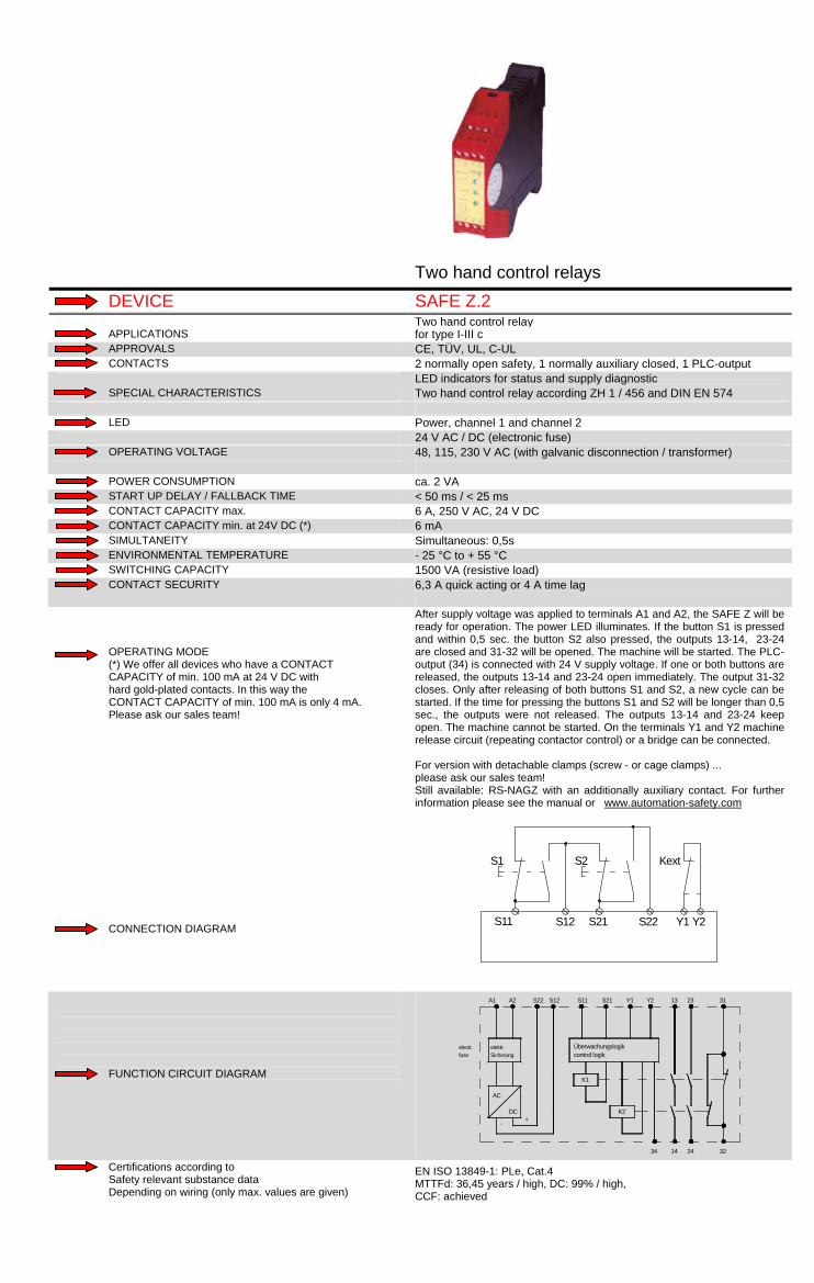
Two hand control relays DEVICE SAFE Z.2 Two hand control relay APPLICATIONS for type I-III c APPROVALS CE, TÜV, UL, C-UL CONTACTS 2 normally open safety, 1 normally auxiliary closed, 1 PLC-output LED indicators for status and supply diagnostic SPECIAL CHARACTERISTICS Two hand control relay according ZH 1 / 456 and DIN EN 574 LED Power, channel 1 and channel 2 24 V AC / DC (electronic fuse) OPERATING VOLTAGE 48, 115, 230 V AC (with galvanic disconnection / transformer) POWER CONSUMPTION ca. 2 VA START UP DELAY / FALLBACK TIME < 50 ms / < 25 ms CONTACT CAPACITY max. 6 A, 250 V AC, 24 V DC CONTACT CAPACITY min. at 24V DC (*) 6 mA SIMULTANEITY Simultaneous: 0,5s ENVIRONMENTAL TEMPERATURE - 25 °C to + 55 °C SWITCHING CAPACITY 1500 VA (resistive load) CONTACT SECURITY 6,3 A quick acting or 4 A time lag OPERATING MODE (*) We offer all devices who have a CONTACT CAPACITY of min. 100 mA at 24 V DC with hard gold-plated contacts. In this way the CONTACT CAPACITY of min. 100 mA is only 4 mA. Please ask our sales team! CONNECTION DIAGRAM
After supply voltage was applied to terminals A1 and A2, the SAFE Z will be ready for operation. The power LED illuminates. If the button S1 is pressed and within 0,5 sec. the button S2 also pressed, the outputs 13-14, 23-24 are closed and 31-32 will be opened. The machine will be started. The PLC-output (34) is connected with 24 V supply voltage. If one or both buttons are released, the outputs 13-14 and 23-24 open immediately. The output 31-32 closes. Only after releasing of both buttons S1 and S2, a new cycle can be started. If the time for pressing the buttons S1 and S2 will be longer than 0,5 sec., the outputs were not released. The outputs 13-14 and 23-24 keep open. The machine cannot be started. On the terminals Y1 and Y2 machine release circuit (repeating contactor control) or a bridge can be connected. For version with detachable clamps (screw - or cage clamps) ... please ask our sales team! Still available: RS-NAGZ with an additionally auxiliary contact. For further information please see the manual or www.automation-safety.com
S11 S21
S1
S12 S22
S2
Y1 Y2
Kext
FUNCTION CIRCUIT DIAGRAM
S21
Überwachungslogik
K1
+-
DC
AC
electr.fuse
elektr.Sicherung
A1 A2
control logik
S22 S12 S11
34 14 24
K2
32
Y2Y1 13 23 31
Certifications according to Safety relevant substance data Depending on wiring (only max. values are given)
EN ISO 13849-1: PLe, Cat.4 MTTFd: 36,45 years / high, DC: 99% / high, CCF: achieved

Two hand control relays DEVICE SAFE CZ Two hand control relay APPLICATIONS for type IIIc or II APPROVALS CE, (TÜV, UL, C-UL pending) CONTACTS 4 OSSD LED indicators for status and supply diagnostic SPECIAL CHARACTERISTICS wearless contacts, "AND" function between several SAFE C possible, automatic start possible LED Power, channel 1 and channel 2 24 V DC ( + 25 - 20 % ) OPERATING VOLTAGE Overvoltage protection POWER CONSUMPTION ca. 3 W START UP DELAY / FALLBACK TIME < 100 ms / < 25 ms CONTACT CAPACITY max. total current bis 1,8 A CONTACT CAPACITY min. at 24V DC (*) infinite SIMULTANEITY 0,5 s ENVIRONMENTAL TEMPERATURE -25°C to +55°C SWITCHING CAPACITY to 43 W CONTACT SECURITY short circuit proof OPERATING MODE (*) We offer all devices who have a CONTACT CAPACITY of min. 100 mA at 24 V DC with hard gold-plated contacts. In this way the CONTACT CAPACITY of min. 100 mA is only 4 mA. Please ask our sales team! CONNECTION DIAGRAM
In use of the application below the simultaneousness of both switches is monitored (less than 0,5 s). This behaviour corresponds to EN 954-1 safety category 4. This application is suitable for type II of DIN EN 574 and corresponds to EN 954-1 safety category 3. Wiring changes during operation are not allowed and lead to a failure message. Application corresponds to EN 954-1 type IIIc and safety category 4, EN IEC 62061 up to SIL3 and EN ISO 13849-1 up to PLe.
S35 S34 S22S12S11S21 S21S33 S32
S36 S37 A2 14 34 4424A1
0 V DC+24 V DC
Rückführung/feedback controlloop
FUNCTION CIRCUIT DIAGRAM
A1 A2
Power Input circuits
S12 S22 S34 S35 S36
Outputcircuits
Combinationcircuit
S11 S21 S33
MCU1<Controller 1>
MCU2<Controller 2>Sa
fety
out
put c
ircui
ts
14
24
34
44
S32S37
Certifications according to Safety relevant substance data Depending on wiring (only max. values are given)
EN ISO 13849-1/ EN 61508: PLe, Cat. 4 / SIL3 MTTFd: 163 years / high, DC: high, CCF: achieved PFH: 2,87*10-9 1/h, PFD: 2,01*10-6 1/h, SFF: 0,9573

DEVICE SAFE Z Two hand control relay APPLICATIONS for type I-III c APPROVALS CE, TÜV, UL, C-UL CONTACTS 2 normally open safety, 1 normally auxiliary closed LED indicators for status and supply diagnostic SPECIAL CHARACTERISTICS Two hand control relay according ZH 1 / 456 and DIN EN 574 LED Power, channel 1 and channel 2 OPERATING VOLTAGE 24 V DC (electronic fuse) POWER CONSUMPTION ca. 3 VA START UP DELAY / FALLBACK TIME < 50 ms / < 30 ms CONTACT CAPACITY max. 6 A, 250 V AC, 24 V DC CONTACT CAPACITY min. at 24V DC (*) 1 mA SIMULTANEITY Simultaneous: 0,5 s ENVIRONMENTAL TEMPERATURE - 25 °C to + 55 °C SWITCHING CAPACITY 1500 VA (resistive load) CONTACT SECURITY 6 A quick acting or 4 A time lag OPERATING MODE (*) We offer all devices who have a CONTACT CAPACITY of min. 100 mA at 24 V DC with hard gold-plated contacts. In this way the CONTACT CAPACITY of min. 100 mA is only 4 mA. Please ask our sales team! CONNECTION DIAGRAM
After supply voltage was applied to terminals A1 and A2, the SAFE Z.2 will be ready for operation. The power LED illuminates. If the button S1 is pressed and within 0,5 sec. the button S2 is also pressed, the outputs 13-14, 23-24 are closed and 31-32 will be opened. The machine will be started. If one or both buttons are released, the outputs 13-14 and 23-24 open immediately.The output 31-32 closes. Only after releasing the both buttons S1 and S2, a new cycle can be started. If the time for pressing the buttons S1 and S2 will be longer as 0,5 sec., the outputs were not released. The outputs 13-14 and 23-24 keep open. The machine cannot be started. On the terminals Y1 and Y2 machine release circuits (repeating contactor control) can be connected.
S11A2 S21
S1
S22 Y2
S2
FUNCTION CIRCUIT DIAGRAM
S21
Überwachungslogik
K1fuse
+-DC
AC
electr.
elektr.Sicherung
A1 A2
control logik
S22 S11
14 24
K2
32
Y2 13 23 31
Certifications according to Safety relevant substance data Depending on wiring (only max. values are given)
EN ISO 13849-1: PLe, Cat.4 MTTFd: 36,85 years / high, DC: 99% / high, CCF: achieved

Expansion modules DEVICE SAFE X4 / SAFE X4.1 Expansion module APPLICATIONS for emergency stop relay according to VDE 0113 APPROVALS CE, TÜV, UL, C-UL CONTACTS 4 normally open safety and 1 normally safety closed (feedback) With (SAFE X4) and without (SAFE X4.1) opposite polarity between SPECIAL CHARACTERISTICS Easy way to increase the number of contacts Compact housing LED Channel 1, channel 2 and fault 48, 110-127, 230 V AC (with galvanic disconnection/transformer) OPERATING VOLTAGE 24 V AC / DC (without galvanic disconnection, but with a safety POWER CONSUMPTION ca. 4 VA START UP DELAY / FALLBACK TIME - / < 50 ms CONTACT CAPACITY max. 6 A, 250 V AC, 24 V DC, sum of currents < 16 A CONTACT CAPACITY min. at 24V DC (*) 6 mA SIMULTANEITY ENVIRONMENTAL TEMPERATURE - 25°C to + 55 °C SWITCHING CAPACITY 1500 VA CONTACT SECURITY 10 A quick acting OPERATING MODE (*) We offer all devices who have a CONTACT CAPACITY of min. 100 mA at 24 V DC with hard gold-plated contacts. In this way the CONTACT CAPACITY of min. 100 mA is only 4 mA. Please ask our sales team! CONNECTION DIAGRAM
The expansion module is used to increase the number of outputs of a safety relay according to VDE 0113. Several expansion modules can be connected to one safety relay. A supply voltage must be applied at terminals A1 and A2 in order to operate the device. If this is done there is a voltage of 24V DC at terminal U1. Terminals K21 and K1 must be wired as shown in the application examples. To start the module, closed safety circuits from the safety relay must be connected with K21 and K1 and contacts 13-14, 23-24, 33-34, 43-44, 53-53, 63-64, 73-74 and 83-84 close. The LED´s channel 1 and 2 illuminate. The fault LED illuminates if one or more safety circuits are open. The fault LED will be illuminated while the expansion module relay is operational. For version with detachable clamps (screw - or cage clamps) ... please ask our sales team!
U1+ 24VDC
K21 K1
ohne Querschlusssicherheit / without opposite polarity
mit Querschlusssicherheit / with opposite polarity
13
14
23
24
U1+ 24VDC
K1 U220 V
13
14
23
24
K21
FUNCTION CIRCUIT DIAGRAM
elektr. SicherungTransformator /electr. Fusetransformer
Überwachungslogik /
-
AC
A1
K1
Y2
DC+
K2
14 24 34 44
Y1
Controller Logic
A2 U1 U22 K1 K21 13 23 33 43
Certifications according to Safety relevant substance data Depending on wiring (only max. values are given)
EN ISO 13849-1: PLe, Cat.4 MTTFd: 185 years / high, DC: 99% / high, CCF: achieved
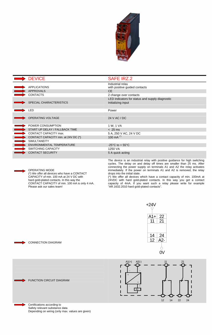
DEVICE SAFE IRZ.2 Industrial relay APPLICATIONS with positive guided contacts APPROVALS CE CONTACTS 2 change over contacts LED indicators for status and supply diagnostic SPECIAL CHARACTERISTICS Initializing input LED Power OPERATING VOLTAGE 24 V AC / DC POWER CONSUMPTION 1 W, 1 VA START UP DELAY / FALLBACK TIME < 25 ms CONTACT CAPACITY max. 5 A, 250 V AC, 24 V DC CONTACT CAPACITY min. at 24V DC (*) 100 mA (*) SIMULTANEITY ENVIRONMENTAL TEMPERATURE -25°C to + 55°C SWITCHING CAPACITY 1250 VA CONTACT SECURITY 5 A quick acting OPERATING MODE (*) We offer all devices who have a CONTACT CAPACITY of min. 100 mA at 24 V DC with hard gold-plated contacts. In this way the CONTACT CAPACITY of min. 100 mA is only 4 mA. Please ask our sales team! CONNECTION DIAGRAM
The device is an industrial relay with positive guidance for high switching cycles. The delay on and delay off times are smaller than 25 ms. After connecting the power supply on terminals A1 and A2 the relay activates immediately. If the power on terminals A1 and A2 is removed, the relay drops into the initial state. (*) We offer all devices which have a contact capacity of min. 100mA at 24VDC with hard gold-plated contacts. In this way you get a contact capacity of 4mA. If you want such a relay please write for example "AR.1632.2010 hard gold-plated contacts".
A1+11 21
22
241412 A2-
+24V
0V
FUNCTION CIRCUIT DIAGRAM
11
=
-K1
+
12
A2(-)
~ ~
=
A1(+)
2214 24
21
Certifications according to Safety relevant substance data Depending on wiring (only max. values are given)

DEVICE RS-NAGX 5 Expansion module APPLICATIONS for emergency stop relay according to VDE 0113 APPROVALS CE, TÜV (UL, C-UL pending) CONTACTS 5 normally open safety and 1 normally safety closed (feedback) LED indicators for status and supply diagnostic SPECIAL CHARACTERISTICS Easy way to increase the number of contacts Compact housing LED Channel 1 and channel 2 24 V AC / DC (without galvanic disconnection, but with a safety OPERATING VOLTAGE resistor) POWER CONSUMPTION ca. 2,4 VA START UP DELAY / FALLBACK TIME < 30 ms CONTACT CAPACITY max. 6 A, 250 V AC, 24 V DC, sum of currents <16 A CONTACT CAPACITY min. at 24V DC (*) 6 mA SIMULTANEITY ENVIRONMENTAL TEMPERATURE - 25°C to + 55 °C SWITCHING CAPACITY 1500 VA CONTACT SECURITY 6 A quick acting or 4 A time lag OPERATING MODE (*) We offer all devices who have a CONTACT CAPACITY of min. 100 mA at 24 V DC with hard gold-plated contacts. In this way the CONTACT CAPACITY of min. 100 mA is only 4 mA. Please ask our sales team! CONNECTION DIAGRAM
Input circuit A1 is to be connected with one of the redundant safety outputs (13-14). Errors of the expansion unit will be announced over the feedback control loop (Y1-Y2) and the next activation will be disabled. In case of protected wiring (short current circuit exclusion) and regularly tests, for example during maintenance, up to safety category 4.
A1 A2
+24V
0V
A1 A2
Y1 Y2
X1 X2
z.B. RS-NAGLe.g. RS-NAGL
RS-NAGX5
13 14
FUNCTION CIRCUIT DIAGRAM
K1
K2
DCAC
A1 A2
14 24 34 44 54 Y2
13 23 33 43 53 Y1
Certifications according to Safety relevant substance data Depending on wiring (only max. values are given)
EN ISO 13849-1: PLe, Cat.4 MTTFd: 74,2 years / high, DC: 99% / high, CCF: achieved

Multifunctional DEVICE SAFE FLEX Safety controller APPLICATIONS with choosable multi functions APPROVALS CE, TÜV, UL, C-UL CONTACTS 2 normally open, 1 PNP output LED indicators for status and supply diagnostic SPECIAL CHARACTERISTICS optical failure indication by LEDs Automatic start possible LED Power, channel 1 IN/OUT, channel 2 IN/OUT, failure 24 V DC ( + 20 - 25 % ) OPERATING VOLTAGE Overvoltage protection POWER CONSUMPTION < 3 W START UP DELAY / FALLBACK TIME e-stop,BWS, Two hand,safety gate monitoring relay <= 30ms CONTACT CAPACITY max. 6 A, 250 V AC, 250 V DC CONTACT CAPACITY min. at 24V DC (*) 5 mA SIMULTANEITY depending on the choosen functionality (see technical data) ENVIRONMENTAL TEMPERATURE - 25°C to + 55°C SWITCHING CAPACITY 1500 VA CONTACT SECURITY 6 A quick acting or 4 A time lag OPERATING MODE (*) We offer all devices who have a CONTACT CAPACITY of min. 100 mA at 24 V DC with hard gold-plated contacts. In this way the CONTACT CAPACITY of min. 100 mA is only 4 mA. Please ask our sales team! CONNECTION DIAGRAM
By wiring the following functionality is are choosable: - E-Stop safety controller cat. 4 - safety gate controller cat. 4 - Two-Handed safety controller cat. 3c - ESPE safety controller (light barriers and curtains) cat. 4 and cat.2 - single pole safety devices with cyclic testing cat. 4 Wiring changes during operation are not allowed and lead to a failure message.
S32 S33 S22S12S11 S21S34
A1
Rückführung/feedback control loop
S35 S36 A2
Start
+24V DC 0V DC
FUNCTION CIRCUIT DIAGRAM
A1
S33 S36 S12 S31 13 23
14 24
S11 S21S32S22 S34 S35
INPUT CIRCUIT
Mikrocontroller 1 K1
K2
POWER
OUTPUT CIRCUIT
A2
Mikrocontroller 2
Certifications according to Safety relevant substance data Depending on wiring (only max. values are given)
EN ISO 13849-1/ EN 62061: PLe, Cat. 4 / SIL3 MTTFd: >100 years / high, DC: 99% / high, CCF: achieved PFH: 2,15*10-9 1/h, SSF: 94,65%

Muting DEVICE RS-NAGU.12 Muting control APPLICATIONS APPROVALS CE, TÜV CONTACTS 3 electronic safety semiconductor outputs (2 PNP / 1 NPN) 4 muting sensors connectable SPECIAL CHARACTERISTICS Control of filament of external muting lamp Suitable for ESPE-2 with selftest LED Power, channel 1, channel 2, fault and restart interlock OPERATING VOLTAGE 24 V DC POWER CONSUMPTION 10 W (up to 60 W including peripheral devices) START UP DELAY / FALLBACK TIME < 6 ms CONTACT CAPACITY max. 0,7 - 1,5 A(*2), 24 V DC CONTACT CAPACITY min. at 24V DC (*) 1 mA SIMULTANEITY Simultaneous of the muting sensors : 3 s ENVIRONMENTAL TEMPERATURE - 25°C to + 55°C SWITCHING CAPACITY 17 W CONTACT SECURITY outputs are permanently short circuit proof OPERATING MODE (*) We offer all devices who have a CONTACT CAPACITY of min. 100 mA at 24 V DC with hard gold-plated contacts. In this way the CONTACT CAPACITY of min. 100 mA is only 4 mA. Please ask our sales team! CONNECTION DIAGRAM
RS-NAGU.12 could be used together with safety light barriers and safety light curtains with safety category 2 which have a selftest. The RS-NAGU.12 is used for muting of safety light barriers and safety light curtains. So that material - transport to or from a machine can be done. Applications can be found in the automotive industry, packaging machines or at highly automated production systems. The differentiation between human beings and material flow is done with up to four muting sensors or two safety light barriers. Inductive sensors or mechanical switches can also be used as muting sensors. After connection as per application guide, the device will be ready as soon as the power LED and channel are illuminated. If LED channel 1 is blinking, a fault exists or a wrong connection has been made. In ready condition the RS-NAGU.12 can be started by pushing the start key. If it cannot be started, then at least one of the muting sensors is blocked or not connected correctly. If a muting sensor is blocked by material supply, a muting can be initiated by actuation of the key switch. If the light barrier is interrupted after a muting cycle, RS-NAGU.12 can be activated by pushing the start key after the failure has been fixed. As soon as muting sensors 1 and 2, respectively 3 and 4 will be activated within 3 sec., the RS-NAGU.12 will initiate a muting cycle. Interruption of the light barrier will not cause a stop of the machine. If 3 of the 4 muting sensors are deactivated, the muting cycle will end after 0.25 sec.
FUNCTION CIRCUIT DIAGRAM
(*2) 1,5 A permanent output (1 output) up to 4,5 A start-up current (t<1s, Uv>21,6V), 1 A permanent current (2 outputs), 0,7 A permanent current (3 outputs) Notice: please ask for detailed documentation.
Certifications according to Safety relevant substance data Depending on wiring (only max. values are given)
EN ISO 13849-1: PLe, Cat.4 MTTFd: >100 years / high, DC: 99% / high, CCF: achieved

DEVICE RS-NAGU.1 / RS-NAGU.2f Muting control APPLICATIONS RS-NAGU.1 : CE, TÜV, UL, C-UL, APPROVALS RS-NAGU.2f : CE, UL, C-UL CONTACTS RS-NAGU.1: 3 electr. Safety semicond. outp. / RS-NAGU.2 f: 3 normally 4 muting sensors connectable SPECIAL CHARACTERISTICS Control of filament of external muting lamp pushbutton LED Power indication, channel 1, channel 2, fault and restart interlock OPERATING VOLTAGE 24 V DC POWER CONSUMPTION 10 W (up to 60W including peripheral devices ) START UP DELAY / FALLBACK TIME RS-NAGU.1 : < 6 ms - RS-NAGU.2f : < 20 ms CONTACT CAPACITY max. RS-NAGU.1 : 0,7 - 1,5 A(*2), 24 V DC / RS-NAGU.2f : 3,5 - 6 A(*3), 24 V CONTACT CAPACITY min. at 24V DC (*) RS-NAGU.1 : 1 mA / RS-NAGU.2f: 100 mA(*) SIMULTANEITY Simultaneous of the muting sensors : 3 s ENVIRONMENTAL TEMPERATURE - 25°C to + 55°C SWITCHING CAPACITY NAGU.1 : 17 W, NAGU.2f: 84 W CONTACT SECURITY RS-NAGU.1 : outputs are permanently short circuit proof RS-NAGU.2f :4 A quick acting or 3,15 A time lag OPERATING MODE (*) We offer all devices who have a CONTACT CAPACITY of min. 100 mA at 24 V DC with hard gold-plated contacts. In this way the CONTACT CAPACITY of min. 100 mA is only 4 mA. Please ask our sales team! CONNECTION DIAGRAM
NAGU is used for muting of safety light barriers and safety light curtains, so that material - transport to or from a machine can be done. Applications can be found in the automotive industry, packaging machines or at highly automated production systems. The differentiation between human beings and material flow is done with up to four muting sensors or two safety light barriers. Inductive sensors or mechanical switches can also be used as muting sensors. After connection as per application guide, the device will be ready as soon as the power LED´s and channel 1 and channel 2 are illuminated. If LED´s channel1/2 are blinking, a fault exists or a wrong connection has been made. In ready condition the RS-NAGU can be started by pushing the start key. If it cannot be started, then at least one of the muting sensors is blocked or not connected correctly. If a muting sensor is blocked by material supply, a muting can be initiated by actuation of the key switch. If the light barrier is interrupted after a muting cycle, RS-NAGU can be activated by pushing the start key after the failure has been fixed. As soon as muting sensors 1 and 2, respectively 3 and 4 will be activated within 3 sec., the RS-NAGU will initiate a muting cycle. Muting takes place so long the inputs of both groups of muting sensors are in active state plus 0,25s time-delay. RS-NAGU.1: 3 electronic safety semiconductor outputs. RS-NAGU 2f: 3 normally open safety, 3 normally open signal outputs (release, and safety light barrier) RS-NAGU (housing with detachable terminal strips) also this unit is available
FUNCTION CIRCUIT DIAGRAM
(*) We offer all devices which have a contact capacity of min. 100 mA at 24 VDC with hard gold-plated contacts. In this way you get a contact capacity of 4 mA. (*2) 1,5 A permanent current (1 output) up to 4,5 A peak current (t<1s,UV>21,6V), 1 A permanent current (2outputs), 0,7 A permanent current (3 outputs) (*3) 6 A permanent current (1 output), 3,5 A permanent current (3 outputs)
Certifications according to Safety relevant substance data Depending on wiring (only max. values are given)
EN ISO 13849-1: PLe, Cat.4 MTTFd: >100 years / high, DC: 99% / high, CCF: achieved

Safety on Bus DEVICE SAFE IL1 / IL2 / ILL / IL2 Interbus INLINE devices ( emergency stop, safety gate controlling, APPLICATIONS two hand controlling, safety light curtains/barriers) APPROVALS CE, TÜV CONTACTS 1 normally open safety LED indicators for status and supply diagnostic SPECIAL CHARACTERISTICS diagnostic with fieldbus, integration in the inline system LED Channel 1, channel 2, US, UM, diagnostic 24 V DC OPERATING VOLTAGE POWER CONSUMPTION ca. 1,7 W START UP DELAY / FALLBACK TIME -- / < 20 ms CONTACT CAPACITY max. 4A DC, 24 V CONTACT CAPACITY min. at 24V DC (*) 10 mA SIMULTANEITY ENVIRONMENTAL TEMPERATURE -25°C to +55°C SWITCHING CAPACITY 120 W CONTACT SECURITY 4 A time lag OPERATING MODE (*) We offer all devices who have a CONTACT CAPACITY of min. 100 mA at 24 V DC with hard gold-plated contacts. In this way the CONTACT CAPACITY of min. 100 mA is only 4 mA. Please ask our sales team! CONNECTION DIAGRAM
For the operation of the device the device must be connected into a Inline station. The voltage supply is taken over the Inlinesystem. The LED "UM" illuminates. For a detailed description please see appropriate manuals. Please pay attention to our circuit breaker SAFE IL2. Sales only on inquiry
FUNCTION CIRCUIT DIAGRAM
Notice: please ask for detailed documentation.
Certifications according to Safety relevant substance data Depending on wiring (only max. values are given)

Safety standstill monitor DEVICE SAFE SM (OUTLOOK) Safety standstill monitor APPLICATIONS APPROVALS CE, (TÜV, UL, C-UL pending) CONTACTS 2 normally open, 1 PNP output LED indicators for status and supply diagnostic SPECIAL CHARACTERISTICS optical failure indication by LEDs Automatic start possible LED Power, channel 1 IN/OUT, channel 2 IN/OUT, failure 24 V DC ( + 20 - 25 % ) OPERATING VOLTAGE Overvoltage protection POWER CONSUMPTION < 3 W START UP DELAY / FALLBACK TIME frequency dependent CONTACT CAPACITY max. 6 A, 250 V AC, 250 V DC CONTACT CAPACITY min. at 24V DC (*) 5 mA SIMULTANEITY ENVIRONMENTAL TEMPERATURE - 25°C to + 55°C SWITCHING CAPACITY 1500 VA CONTACT SECURITY 6 A quick acting or 4 A time lag OPERATING MODE (*) We offer all devices who have a CONTACT CAPACITY of min. 100 mA at 24 V DC with hard gold-plated contacts. In this way the CONTACT CAPACITY of min. 100 mA is only 4 mA. Please ask our sales team! CONNECTION DIAGRAM
The riese SAFE SM is a safe standstill monitor. It is designed to monitor safe speeds. Digitally switches e.g. inductive sensors or ESPD’s are supported. SAFE SM is a two channel device. Therefore, two digitally switches are necessary. Four safe speeds are monitored: 0.2 Hz, 0.5 Hz, 1.0 Hz and 2.0 Hz, the shifting is done via configuration wirings.
S11 S12 S34S33S22S21
A1
Rückführung/ feedbackcontrol loop
A2
+24V DC 0V DC
2x Induktionsgeber/induction-type pulse generator
FUNCTION CIRCUIT DIAGRAM
A1
S33 S36 S12 S31 13 23
14 24
S11 S21S32S22 S34 S35
INPUT CIRCUIT
Mikrocontroller 1 K1
K2
POWER
OUTPUT CIRCUIT
A2
Mikrocontroller 2
Certifications according to Safety relevant substance data Depending on wiring (only max. values are given)

21
The replacement of EN 954-1 Previously, the machine constructing engineer had, according to the EN 954-1 (safety-related parts of control systems, part 1: General design principles) to proof the compliance of the general safety requirements according to the European machinery directive. This standard demanded a risk analysis with the resulting safety categories (B, 1, 2, 3, 4). B stands for low and almost no safety respectively, 4 stands for high safety. The safety devices for a system were chosen with the safety category. The EN 954-1 was replaced because programmable electronic systems were considered insufficiently and the time response (e.g. testing intervals, life cycles) and the failure probability of components were not considered. The following standards EN 13849-1 (safety of machines – safety-related parts of control systems, part 1: General design principles) and EN 62061 (safety of machines – functional safety of electrical, electronic and programmable electronic control systems) create remedy and consider the above approaches. Definition of the safety requirements It is divided into two parts: Safety of machines and the functional safety. Safety of machines After finished risk evaluation according to EN ISO 14121-1, measures for reducing of the detected risks will be defined. Afterwards, the risks will be reduced up to an acceptable residual risk. Functional safety The functional safety follows from the results of the machinery safety. The functional safety is divided into 6 steps: 1. Definition of the safety-technological requirements 2. Selection of the required performance 3. Safety design 4. Definition of the achived performance 5. Verification 6. Validation Definition of the safety-technological requirements The required safety function characteristics are defined e.g. ESPD-function with automatic start, no simultaneity, etc. and a detailed description with the necessary interfaces to the other parts of control systems will be prepared. Selection of the required performance The definition is done with a risk graph. For new systems it can be generally done with two standards: EN 13849-1 (Safety of machines – safety-related parts of control systems, part 1: General design principles) With the risk graph it is possible to investigate all safety-related functions and areas of a machine respectively. The results are the so-called Performance Level / PL (a-e). The PL is needed for the selection of the safety setup and the corresponding components including wiring. The a stands for low safety and the e for high safety.
a
b
c
d
e
starting point
high safety
P2P1
P2
P1P2
P1P2
P1F1
F2
F1
F2
S1
S2
low safety
S - severity of injuryS1 - slight injury (usually reversible)S2 - serious injury, including death (usually irreversible)
F - frequency and duration of exposure to the hazardF1 - rarely to many a time residenceF2 - more likely to permanent residence
P - the probability of avoidance of a hazardous eventP1 - possible under certain conditionsP2 - hardly possible
EN 62061 (Safety of machines - functional safety of safety-related electrical, electronic and programmable electronic control systems) With the risk graph it is possible to investigate all safety-relevant functions and areas of a machine respectively. The results are the so-called Safety Integrity Level / SIL (1 - 3).The SIL is required for the selection of the safety setup and the corresponding components including wiring. The 1 stands for low safety and the 3 for high safety.
Class K (=F+P+A) Effect and severity S
Frequency and duration F
Probability P
Avoidance A 3-4 5-7 8-10 11-13 14-15
Death, losing an eye or arm
4 ≤ 1 h 5 very high 5 SIL2 SIL2 SIL2 SIL3 SIL3
Permanent, losing a finger
3 > 1 h - ≤ 1day 5 likely 4 OM SIL1 SIL2 SIL3
Reversible, requiring attention from a medical practioner
2 > 1 day - ≤ 2 weeks 4 possible 3 impossible 5 OM SIL1 SIL2
Requiring first help 1 > 2 weeks - ≤ 1 year 3 rarely 2 possible 3 OM SIL1 > 1 year 2 negligible 1 likely 1 OM = other measures advised Safety design The safety function described in step 1 is designed. The single components are defined, e.g. safety relais SAFE CL for the ESPD-function. Definition of the achived performance The actual performance of the safety function is detected. The safety function is divided in sensors, logic and actuators. The parameters required to calculation are provided by the component manufactures. Verification For each single safety function, the in step 4 achieved performance has to be bigger or equal as the in step 2 defined required performance. If this is not the case the safety function has to be improved. Validation For the safety function, the validation ensures that all safety-relevant parts achieve the requirements.
required Performance Level (PL)

22
Technical data ► Voltage range SAFE 1/1.1 / SAFE 2/2.1/2.2 / SAFE S.6 / SAFE 4/4.1 / SAFE M 0,9 to 1,1 UB RS-NAGV / RS-NAGT/T.1 / SAFE L/L.1 / SAFE L.2 / SAFE Z / SAFE IRZ.2 RS-NAGU.12 / RS-NAGU.1 / RS-NAGU.2f RS-NAGMP/P.1 / RS-NAGA/AO 0,85 to 1,1 UB SAFE IL1 / SAFE 5/5.1 / RS-NAGL/L.1 / SAFE ILL / SAFE Z.2 / RS-NAGZ / SAFE ILZ SAFE X4/4.1 / RS-NAGX5 / SAFE IL2 / FI1 SAFE C1, CL, CM, CZ, SAFE TU/ TA/ TN/ TR/ TON, SAFE FLEX, FLEX T, SAFE SM 0,8 to 1,25 UB FA1 over ASI-Bus ►Clearance and creeping distance DIN EN 50178, or DIN VDE 0160 at pollution grade 2, over voltage category 3/300V ► max. switching voltage SAFE IL2 : 12 A AC, cos φ = 1 RS-NAGMP/MP.1 : 8 A AC, cos φ = 1; 8 A DC, τ =0 SAFE IRZ.2, SAFE 1/ 1.1/ 4/ 4.1/ M: 5 A AC, cos φ = 1; 5 A DC, τ =0 SAFE IL1, SAFE IL L, SAFE IL Z, RS-NAGV: 4 A AC, cos φ = 1; 4 A DC, τ =0 RS-NAGU.2f: 6 A DC (1 Kontakt), τ = 0 RS-NAGU.1/RS-NAGU.12: 1,5 A DC (1 Kontakt), τ = 0 SAFE C1, SAFE CL, SAFE CM, SAFE CZ: 1,8 A DC Other : 6 A AC, cos φ = 1; 6 A DC, τ =0 ► Protection classes Space requirements : IP 54 Housing : IP 40 Terminal area : IP 20 ► Mechanical life time 107 switching cycles ► Electronical life time 105 switching cycles ► Mounting DIN rail EN 50022 ( 35 mm ) Pay attention to housing with detachable terminal strips: if you would like to detach the terminal strips please take away the power first. ► The ground wire has to be connected to terminal PE when an auxillary voltage used (at the terminals A1 and A2) UB~ / whit galvanic disconnection to connect a protective conductor. By AC/DC or DC - devices is this not permitted. All operating instructions can be found under www.automation-safety.com
Developement Production
Special advantages ► emergency stop according to EN60204 ► redundant positiv guided relay ► cyclical monitoring of the function ► housing with detachable terminal strip (for a quick change of the devices) by the NAG-line (without RS-NAGU.1 / RS-NAGU.2f / RS-NAGU.1f / RS-NAGU.12) ► wireless layout ► housing of self extinguishing plastic according to UL 94-V1 ► 100% computer assisted check
Testing area
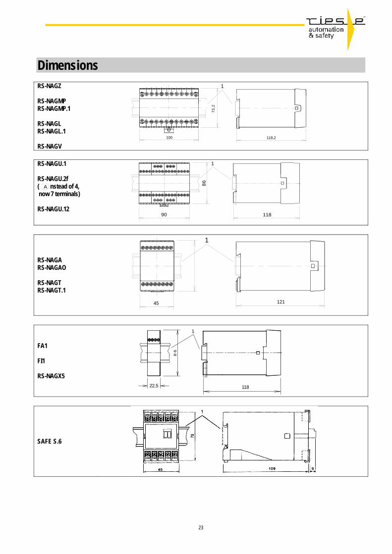
23
118
8 6
1
22,5
Dimensions
RS-NAGZ RS-NAGMP RS-NAGMP.1 RS-NAGL RS-NAGL.1 RS-NAGV
RS-NAGU.1 RS-NAGU.2f ( instead of 4, now 7 terminals) RS-NAGU.12
RS-NAGA RS-NAGAO RS-NAGT RS-NAGT.1
FA1 FI1 RS-NAGX5
SAFE S.6
7 3 , 2
100 118,2
1
90 118
8 6
1
45
7 3
1
121
A

24
Dimensions
SAFE 1 SAFE 1.1 SAFE 2 SAFE 2.1 SAFE 2.2 SAFE Z SAFE IRZ.2 ( 8 terminals)
B[mm] SAFE 4/4.1 22,5 SAFE 5/5.1 22,5 SAFE C1 22,5 SAFE CL 22,5 SAFE CM 22,5 SAFE CZ 22,5 SAFE M/M.1 22,5 SAFE L.2 22,5 SAFE X4/4.1 22,5 SAFE Z.2 22,5 SAFE FLEX 22,5 SAFE FLEX T 45 SAFE SM 22,5 SAFE T 35 SAFE TON 35
SAFE IL2
SAFE IL1 SAFE ILL SAFE ILZ
Legend: 1 - Attachment rail DIN EN 50022 Printed: 01.03.2010 We reserve the right to make changes to the technical specification. Not responsible for typographical text and drawing errors. With this leaflet all leaflets before are no longer valid. Since text and pictures in this folder are only for handling and illustration, we cannot take over adhesion for possible errors.
63
73

25
Product- / part number index Type: Voltage: Part-nr.: Type: Voltage: Part-nr.: NAGA 24 V DC AR.9663.9000 SAFE 1 24 V AC/DC AR.9655.2000 NAGA 24 V AC AR.9663.8000 SAFE 1.1 24 V AC/DC AR.9654.2000 NAGA 24 V AC/DC AR.9663.2000 SAFE 2 24 V AC/DC AR.9656.2000 NAGA 48 V AC AR.9663.3000 SAFE 2.1 24 V AC/DC AR.9657.2000 NAGA 110-127 V AC AR.9663.4000 SAFE 2.2 24 V AC/DC AR.9657.2010 NAGA 230 V AC AR.9663.5000 SAFE 4 24 V AC/DC AR.9659.2000 NAGAO 24 V DC AR.9665.9000 SAFE 4 110-127 V AC AR.9659.4000 NAGAO 24 V AC AR.9665.8000 SAFE 4 230 V AC AR.9659.5000 NAGAO 24 V AC/DC AR.9665.2000 SAFE 4.1 24 V AC/DC AR.9660.2000 NAGAO 48 V AC AR.9665.3000 SAFE 4.1 110-127 V AC AR.9660.4000 NAGAO 110-127 V AC AR.9665.4000 SAFE 4.1 230 V AC AR.9660.5000 NAGAO 230 V AC AR.9665.5000 SAFE 5 24 V AC/DC AR.9645.2000 NAGL 24 V AC/DC AR.9610.2000 SAFE 5.1 24 V AC/DC AR.9646.2000 NAGL 48 V AC AR.9610.3000 SAFE C1 24 V DC AR.9680.9000 NAGL 110-127 V AC AR.9610.4000 SAFE CL 24 V DC AR.9680.9001 NAGL 230 V AC AR.9610.5000 SAFE CM 24 V DC AR.9680.9002 NAGL.1 24 V DC AR.9610.9003 SAFE CZ 24 V DC AR.9680.9003 NAGMP 12 V DC AR.9605.1001 SAFE FLEX 24 V DC auf Anfrage NAGMP 24 V DC AR.9605.9001 SAFE L.2 24 V AC/DC AR.9671.2100 NAGMP 24 V AC AR.9605.8001 SAFE M 24 V AC/DC AR.9647.2000 NAGMP 24 V AC/DC AR.9605.2001 SAFE M.1 24 V AC/DC AR.9648.2000 NAGMP 110-127 V AC AR.9605.4001 SAFE S.6 24 V DC AR.9650.9000 NAGMP 230 V AC AR.9605.5001 SAFE S.6 24 V AC AR.9650.8000 NAGMP.1 12 V DC AR.9605.1002 SAFE S.6 24 V AC/DC AR.9650.2000 NAGMP.1 24 V DC AR.9605.9002 SAFE S.6 48 V AC AR.9650.3000 NAGMP.1 24 V AC AR.9605.8002 SAFE S.6 110-127 V AC AR.9650.4000 NAGMP.1 24 V AC/DC AR.9605.2002 SAFE S.6 230 V AC AR.9650.5000 NAGMP.1 110-127 V AC AR.9605.4002 SAFE TN 24 V AC/DC AR.9621.2010 NAGMP.1 230 V AC AR.9605.5002 SAFE TA 24 V AC/DC AR.9621.2011 NAGT 24 V AC/DC AR.9661.2000 SAFE TR 24 V AC/DC AR.9621.2012 NAGT 110-127VAC/24VDC AR.9661.4000 SAFE TU 24 V AC/DC AR.9621.2013 NAGT 230 V AC AR.9661.5000 SAFE TON 24 V AC/DC AR.9621.2100 NAGT.1 110-127VAC/24VDC AR.9661.4005 SAFE X4 24 V AC/DC AR.9613.2000 NAGT.1 230 V AC AR.9661.5005 SAFE X4 48 V AC AR.9613.3000 NAGU.12 24 V DC AR.9667.9012 SAFE X4 110-127 V AC AR.9613.4000 NAGU.1 24 V DC AR.9667.9010 SAFE X4 230 V AC AR.9613.5000 NAGU.2f 24 V DC AR.9667.9020 SAFE X4.1 24 V AC/DC AR.9613.2010 NAGV 24 V DC AR.9640.9000 SAFE X4.1 48 V AC AR.9613.3010 NAGV 24 V AC AR.9640.8000 SAFE X4.1 110-127 V AC AR.9613.4010 NAGV 24 V AC/DC AR.9640.2000 SAFE X4.1 230 V AC AR.9613.5010 NAGV 110-127 V AC AR.9640.4000 SAFE Z 24 V DC AR.9672.9000 NAGV 230 V AC AR.9640.5000 SAFE Z.2 24 V AC/DC AR.9673.2000 NAGX5 24 V AC/DC AR.9615.2000 SAFE Z.2 48 V AC AR.9673.3000 SAFE Z.2 110-127 V AC AR.9673.4000 SAFE Z.2 230 V AC AR.9673.5000 Only for spare part: No longer available:
Type: Voltage: Part-nr.: Type: Voltage: Part-nr.: Succeding product FA 1 24 V DC auf Anfrage NAGE 24 V AC AR.9607.8000 NAGMP/P.1 FI 1 24 V DC auf Anfrage NAGE 24 V AC/DC AR.9607.2000 NAGMP/P.1 NAGU.1b 24 V DC auf Anfrage NAGE 24 V DC AR.9607.9000 NAGMP/P.1 NAGZ 24 V DC AR.9611.9000 NAGE 110-127 V AC AR.9607.4000 NAGMP/P.1 NAGZ 24 V AC AR.9611.8000 NAGE 230 V AC AR.9607.5000 NAGMP/P.1 NAGZ 48 V AC AR.9611.3000 NAGK 12 V AC/DC AR.9662.1000 NAGA bzw. NAGA/O NAGZ 110-127 V AC AR.9611.4000 NAGK 24 V AC AR.9662.2000 NAGA bzw. NAGA/O NAGZ 230 V AC AR.9611.5000 NAGK 110-127 V AC AR.9662.4000 NAGA bzw. NAGA/O SAFE IL.1 24 V DC auf Anfrage NAGK 230 V AC AR.9662.5000 NAGA bzw. NAGA/O SAFE IL.2 24 V DC auf Anfrage NAGM 12 V AC/DC AR.9605.1000 NAGMP bzw. NAGMP.1 SAFE IL L 24 V DC auf Anfrage NAGM 24 V AC AR.9605.8000 NAGMP bzw. NAGMP.1 SAFE IL Z 24 V DC auf Anfrage NAGM 24 V AC/DC AR.9605.2000 NAGMP bzw. NAGMP.1 SAFE IRZ.2 24 V AC/DC AR.1632.2010 NAGM 24 V DC AR.9605.9000 NAGMP bzw. NAGMP.1 SAFE L 24 V AC/DC AR.9671.2000 NAGM 110-127 V AC AR.9605.4000 NAGMP bzw. NAGMP.1 SAFE L.1 24 V AC/DC AR.9671.2010 NAGM 230 V AC AR.9605.5000 NAGMP bzw. NAGMP.1 NAGX4 24 V AC AR.9614.8000 SAFE X.4 bzw. X4.1 oder NAGX5 NAGX4 24 V AC/DC AR.9614.2000 SAFE X.4 bzw. X4.1 oder NAGX5 Following devices are still available NAGX4 24 V DC AR.9614.9000 SAFE X.4 bzw. X4.1 oder NAGX5 with some changes NAGX4 110-127 V AC AR.9614.4000 SAFE X.4 bzw. X4.1 NAGU 24 V DC AR.9667.9000 NAGX4 230 V AC AR.9614.5000 SAFE X.4 bzw. X4.1 detachable clamps NAGX8 24 V AC AR.9618.8000 zwei SAFE X.4 bzw. X4.1 oder NAGX5 NAGX8 24 V AC/DC AR.9618.2000 zwei SAFE X.4 bzw. X4.1 oder NAGX5 NAGX8 24 V DC AR.9618.9000 zwei SAFE X.4 bzw. X4.1 oder NAGX5 NAGX8 110-127 V AC AR.9618.4000 zwei SAFE X.4 bzw. X4.1 NAGX8 230 V AC AR.9618.5000 zwei SAFE X.4 bzw. X4.1 NAGP 24 V AC AR.9601.8000 NAGMP NAGP 24 V AC/DC AR.9601.2000 NAGMP NAGP 24 V DC AR.9601.9000 NAGMP NAGP 48 V AC AR.9601.3000 NAGMP NAGP 110-127 V AC AR.9601.4000 NAGMP NAGP 230 V AC AR.9601.5000 NAGMP
Relevant information: partly also available with hard gold-plated contacts. Please ask for price and delivery time by hard gold-plated contacts. All operating instructions can be found under www.automation-safety.com

Infos on our business division EMS (electronic manufacturing service) :
► Our customers are situated in the business of engineering, automation, automotive, medical technology and control devices.► riese electronic employs 120 staff at it's two plants in Horb (Baden-Württemberg) and Langenwolschendorf (Thuringia).► partners in Hungary and China
Development, production and tests for user-specific electronic devices and assemblies www.riese-electronic.com
26

Further product line on our business division A+S (automation & safety) :
Special features► 12 V relays, e.g. for vehicles, vehicle mountings We have developed a number of relays especially for this purpose. Not all types are included in this leaflet so please call us for details.► 24 V relays, e.g. for railways, tram systems. Peculiar to railways and tram systems is the fact that the voltage changes depending on the number of vehicles. We have managed to overcome these and other specific problems.► Brand-name labeling. Do you need relays with your company logo? No problem!► Special designs. If you can't find the relay you're looking for in our range, then please contact our design department. We relish the opportunity to discover new ways of optimizing your applications.
producer of time, measuring and safety relays, representative of automation and safety products www.automation-safety.com
Since 1987 riese electronic has been developing, producing and testing the time-delay and measuring relays. We not just test our relay after it´s finished we test it at every step of production! Our testing strategy thoroughly checks all functions of every single relay by means of a computerized testing system which we developed ourselves. We simulate situations in which the worse scenarious happen all at once. Only after such testing does a relay get the "thumbs-up". Therefore, "riese-relays" are ideally situated to rough environments, e.g. severe vibrations, temperature fluctuations or voltage discrepancies.
27