safety recall s34 / nhtsa 16v-302 manual transaxle clutch ...safety recall s34 – manual transaxle...
TRANSCRIPT
Copyright 2016, FCA US LLC, All Rights Reserved (tdb)
November 2016 Dealer Service Instructions for:
Safety Recall S34 / NHTSA 16V-302
Manual Transaxle Clutch Pedal
2012 - 2016 (FF) FIAT 500 vehicles NOTE: This recall applies only to the above vehicles equipped with a Manual
Transaxle (sales code DDF) built from June 22, 2010 through January 29, 2016
(MDH 062200 through 012908).
The clutch cover diaphragm spring on about 39,000 of the above vehicles may
fatigue and/or fracture. A failed clutch cover diaphragm spring may result in the
inability to disengage the clutch, shift gears and the potential for a loss of motive
power. The inability to disengage the clutch, shift gears and/or loss of motive
power could cause a crash without warning.
All involved vehicles must be inspected for a clutch pedal travel limiter. Vehicles
found without a clutch pedal travel limiter must have a new clutch pedal assembly
and a new clutch pedal start switch installed.
Models
IMPORTANT: Some of the involved vehicles may be in dealer new vehicle
inventory. Federal law requires you to complete this recall service on these
vehicles before retail delivery. Dealers should also consider this requirement to
apply to used vehicle inventory and should perform this recall on vehicles in for
service. Involved vehicles can be determined by using the VIP inquiry process.
Subject
Repair
Safety Recall S34 – Manual Transaxle Clutch Pedal Page 2
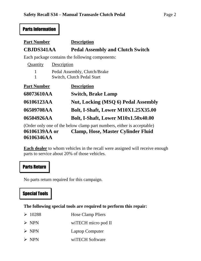
Part Number Description
CBJDS341AA Pedal Assembly and Clutch Switch
Each package contains the following components:
Quantity Description
1 Pedal Assembly, Clutch/Brake
1 Switch, Clutch Pedal Start
Part Number Description
68073610AA Switch, Brake Lamp
06106123AA Nut, Locking (MSQ 6) Pedal Assembly
06509708AA Bolt, I-Shaft, Lower M10X1.25X35.00
06504926AA Bolt, I-Shaft, Lower M10x1.50x40.00
(Order only one of the below clamp part numbers, either is acceptable)
06106139AA or Clamp, Hose, Master Cylinder Fluid
06106346AA
Each dealer to whom vehicles in the recall were assigned will receive enough
parts to service about 20% of those vehicles.
No parts return required for this campaign.
The following special tools are required to perform this repair:
10288 Hose Clamp Pliers
NPN wiTECH micro pod II
NPN Laptop Computer
NPN wiTECH Software
Parts Information
Parts Return
Special Tools
Safety Recall S34 – Manual Transaxle Clutch Pedal Page 3
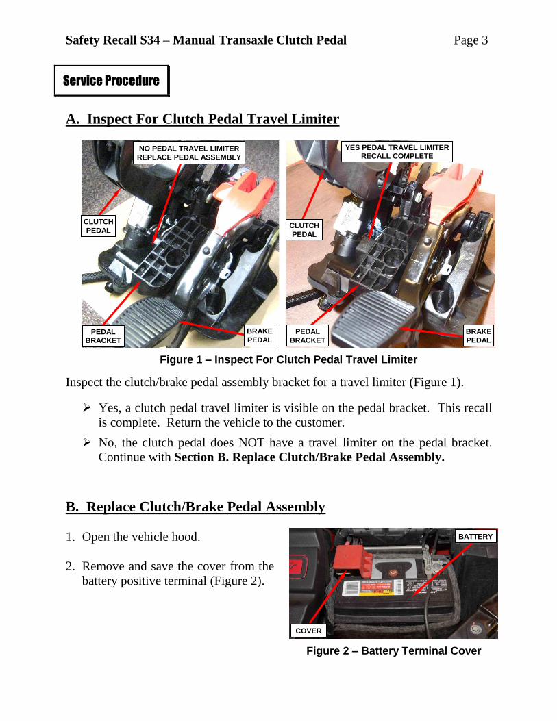
A. Inspect For Clutch Pedal Travel Limiter
Inspect the clutch/brake pedal assembly bracket for a travel limiter (Figure 1).
Yes, a clutch pedal travel limiter is visible on the pedal bracket. This recall
is complete. Return the vehicle to the customer.
No, the clutch pedal does NOT have a travel limiter on the pedal bracket.
Continue with Section B. Replace Clutch/Brake Pedal Assembly.
B. Replace Clutch/Brake Pedal Assembly
1. Open the vehicle hood.
2. Remove and save the cover from the
battery positive terminal (Figure 2).
Service Procedure
Figure 1 – Inspect For Clutch Pedal Travel Limiter
YES PEDAL TRAVEL LIMITER
RECALL COMPLETE NO PEDAL TRAVEL LIMITER
REPLACE PEDAL ASSEMBLY
Figure 2 – Battery Terminal Cover
CLUTCH
PEDAL CLUTCH
PEDAL
BRAKE
PEDAL BRAKE
PEDAL PEDAL
BRACKET
PEDAL
BRACKET
COVER
BATTERY

Safety Recall S34 – Manual Transaxle Clutch Pedal Page 4
3. Disconnect and isolate the battery
negative cable terminal from the
battery negative post (Figure 3). If
equipped with an Intelligent Battery
Sensor (IBS), disconnect the IBS
connector first before disconnecting
the battery negative cable.
4. Remove the Powertrain Control
Module (PCM) ground wire from the
battery negative cable terminal
(Figure 3).
5. Disconnect the battery positive cable
terminal from the battery positive
post (Figure 3).
6. Disconnect the PCM electrical
connectors from the PCM (Figure 4).
7. Remove and save the battery thermal
cover (Figure 4).
8. Remove and save the battery
hold-down retainer (Figure 5).
9. Remove and save the vehicle battery
(Figure 5).
Service Procedure [Continued]
Figure 3 – Battery Terminals
BATTERY POSITIVE
CABLE TERMINAL
Figure 4 – PCM Connectors
Figure 5 – Battery Hold-Down Retainer
PCM GROUND WIRE
BATTERY NEGATIVE
CABLE TERMINAL
PCM ELECTRICAL
CONNECTORS
BATTERY THERMAL
COVER
HOLD-DOWN
RETAINER BATTERY

Safety Recall S34 – Manual Transaxle Clutch Pedal Page 5
10. Release the wire harness retainers from the battery tray (Figure 6).
11. Release the engine wire harness connector retainer from the battery tray and
reposition the wire harness (Figure 6).
12. Remove and save the battery tray retaining nut and two bolts (Figure 6).
13. Remove and save the battery tray (Figure 6).
Service Procedure [Continued]
Figure 6 – Wire Harness Retainers and Battery Tray
BATTERY TRAY
BOLTS NUT
WIRE HARNESS
CONNECTOR RETAINERS
WIRE HARNESS RETAINERS

Safety Recall S34 – Manual Transaxle Clutch Pedal Page 6
14. Raise and support the vehicle.
15. Place an oil drain pan under the
clutch master cylinder.
16. Use a long pick tool to release the
retaining clip then disconnect the
clutch fluid tube from the clutch
master cylinder outlet fitting and
plug both openings (Figure 7).
17. Lower the vehicle.
18. Use special tool 10288 Hose Clamp
Pliers to release the hose clamp then
disconnect the clutch master cylinder
fluid supply hose from the brake
fluid reservoir and plug both
openings (Figure 8).
CAUTION: Discard the hose
clamp; it is not to be reused.
Service Procedure [Continued]
Figure 7 – Clutch Fluid Tube at
Clutch Master Cylinder Outlet Fitting
PICK TOOL CLUTCH MASTER CYLINDER
OUTLET FITTING
RETAINER CLUTCH FLUID TUBE
Figure 8 – Clutch Master Cylinder
Fluid Supply Hose
10288 HOSE CLAMP PLIERS
CLUTCH MASTER CYLINDER FLUID
SUPPLY HOSE
BRAKE FLUID
RESERVOIR
Safety Recall S34 – Manual Transaxle Clutch Pedal Page 7
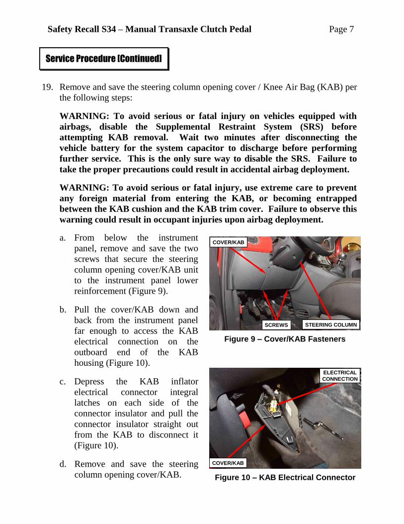
19. Remove and save the steering column opening cover / Knee Air Bag (KAB) per
the following steps:
WARNING: To avoid serious or fatal injury on vehicles equipped with
airbags, disable the Supplemental Restraint System (SRS) before
attempting KAB removal. Wait two minutes after disconnecting the
vehicle battery for the system capacitor to discharge before performing
further service. This is the only sure way to disable the SRS. Failure to
take the proper precautions could result in accidental airbag deployment.
WARNING: To avoid serious or fatal injury, use extreme care to prevent
any foreign material from entering the KAB, or becoming entrapped
between the KAB cushion and the KAB trim cover. Failure to observe this
warning could result in occupant injuries upon airbag deployment.
a. From below the instrument
panel, remove and save the two
screws that secure the steering
column opening cover/KAB unit
to the instrument panel lower
reinforcement (Figure 9).
b. Pull the cover/KAB down and
back from the instrument panel
far enough to access the KAB
electrical connection on the
outboard end of the KAB
housing (Figure 10).
c. Depress the KAB inflator
electrical connector integral
latches on each side of the
connector insulator and pull the
connector insulator straight out
from the KAB to disconnect it
(Figure 10).
d. Remove and save the steering
column opening cover/KAB.
Service Procedure [Continued]
Figure 9 – Cover/KAB Fasteners
Figure 10 – KAB Electrical Connector
COVER/KAB
SCREWS STEERING COLUMN
ELECTRICAL
CONNECTION
COVER/KAB

Safety Recall S34 – Manual Transaxle Clutch Pedal Page 8
20. Position the steering wheel so that
the steering column intermediate
shaft lower pinch bolt is accessible
then using a steering wheel holder,
lock the steering wheel in place to
keep it from rotating. This keeps the
clockspring in the proper orientation
(Figure 11).
21. Remove the steering column
intermediate shaft pinch bolt.
Discard the pinch bolt; it is not to be
reused (Figure 11).
22. Separate the intermediate shaft at the
base of the column from the steering
gear pinion shaft (Figure 11).
23. Position the intermediate shaft so
that the pedal assembly can be
accessed (Figure 11).
24. Remove and save the two nuts from
the fuse panel cover (Figure 12).
25. Remove and save the fuse panel
cover (Figure 12).
26. Remove and save the two screws
from the instrument panel support
bracket (Figure 13).
27. Remove and save the instrument
panel support bracket (Figure 13).
Service Procedure [Continued]
Figure 11 – Steering Column
Intermediate Shaft
Figure 12 – Fuse Panel Cover
Figure 13 – Instrument Panel
Support Bracket
INTERMEDIATE SHAFT
PINION SHAFT
PINCH BOLT
CLUTCH PEDAL
COVER
NUTS
FUSE PANEL
CLUTCH PEDAL
FUSE PANEL
SUPPORT
BRACKET
SUPPORT
BRACKET
SCREWS
CLUTCH PEDAL
Safety Recall S34 – Manual Transaxle Clutch Pedal Page 9
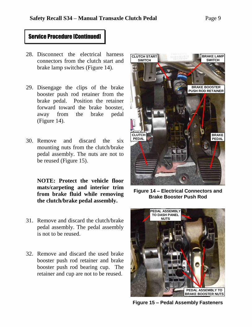
28. Disconnect the electrical harness
connectors from the clutch start and
brake lamp switches (Figure 14).
29. Disengage the clips of the brake
booster push rod retainer from the
brake pedal. Position the retainer
forward toward the brake booster,
away from the brake pedal
(Figure 14).
30. Remove and discard the six
mounting nuts from the clutch/brake
pedal assembly. The nuts are not to
be reused (Figure 15).
NOTE: Protect the vehicle floor
mats/carpeting and interior trim
from brake fluid while removing
the clutch/brake pedal assembly.
31. Remove and discard the clutch/brake
pedal assembly. The pedal assembly
is not to be reused.
32. Remove and discard the used brake
booster push rod retainer and brake
booster push rod bearing cup. The
retainer and cup are not to be reused.
Service Procedure [Continued]
Figure 14 – Electrical Connectors and
Brake Booster Push Rod
Figure 15 – Pedal Assembly Fasteners
CLUTCH PEDAL
BRAKE PEDAL
BRAKE LAMP SWITCH
CLUTCH START SWITCH
BRAKE BOOSTER PUSH ROD RETAINER
PEDAL ASSEMBLY TO DASH PANEL
NUTS
PEDAL ASSEMBLY TO BRAKE BOOSTER NUTS

Safety Recall S34 – Manual Transaxle Clutch Pedal Page 10
33. Install the NEW clutch pedal start switch to the NEW clutch/brake pedal
assembly per the following steps:
a. Insert the switch locating tab into the clutch/brake pedal assembly
(Figure 16).
b. Insert the switch retaining rivet fully into the clutch/brake pedal assembly
(Figure 16).
c. Rotate the locking lever down to expand the retaining rivet securing the
switch in place (Figure 16).
d. Swing the switch activation arm into place making sure to capture the stud
on the clutch pedal (Figure 16).
e. Lock the switch activation arm in place by pushing the lock inward
capturing the clutch pedal stud (Figure 16).
Service Procedure [Continued]
Figure 16 – Clutch Pedal Start Switch Installation
ACTIVATION ARM
START SWITCH
START SWITCH START SWITCH
START SWITCH START SWITCH
LOCATING TAB
RETAINING RIVET
RETAINING RIVET
LOCKING LEVER LOCKING LEVER
LOCK
CLUTCH PEDAL STUD CLUTCH PEDAL STUD LOCK
ACTIVATION ARM
a bg
c
d e
Safety Recall S34 – Manual Transaxle Clutch Pedal Page 11
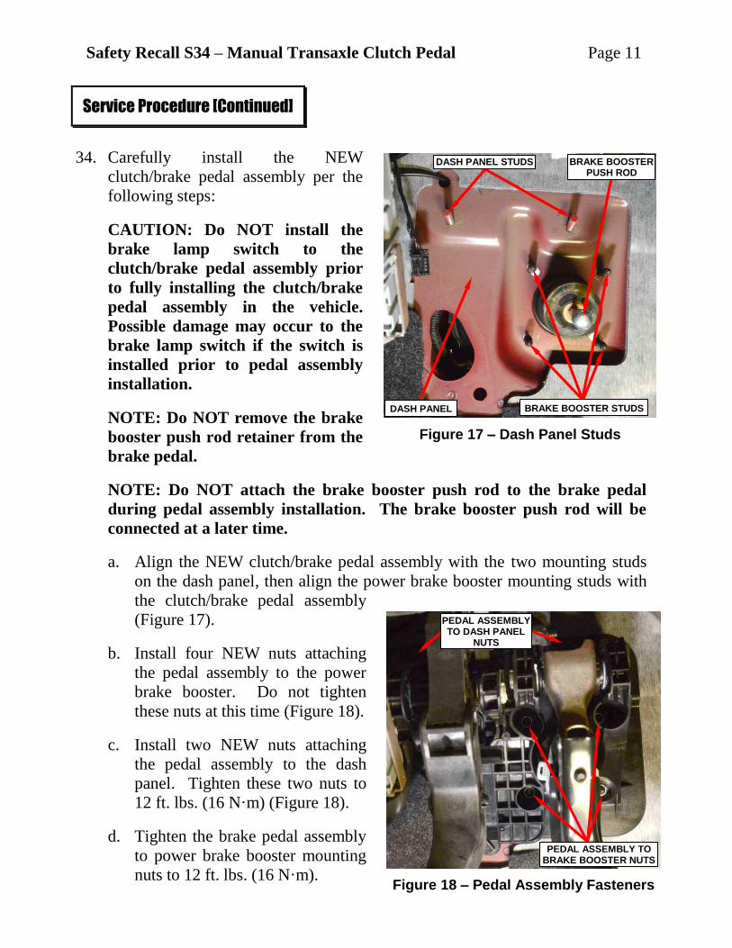
34. Carefully install the NEW
clutch/brake pedal assembly per the
following steps:
CAUTION: Do NOT install the
brake lamp switch to the
clutch/brake pedal assembly prior
to fully installing the clutch/brake
pedal assembly in the vehicle.
Possible damage may occur to the
brake lamp switch if the switch is
installed prior to pedal assembly
installation.
NOTE: Do NOT remove the brake
booster push rod retainer from the
brake pedal.
NOTE: Do NOT attach the brake booster push rod to the brake pedal
during pedal assembly installation. The brake booster push rod will be
connected at a later time.
a. Align the NEW clutch/brake pedal assembly with the two mounting studs
on the dash panel, then align the power brake booster mounting studs with
the clutch/brake pedal assembly
(Figure 17).
b. Install four NEW nuts attaching
the pedal assembly to the power
brake booster. Do not tighten
these nuts at this time (Figure 18).
c. Install two NEW nuts attaching
the pedal assembly to the dash
panel. Tighten these two nuts to
12 ft. lbs. (16 N·m) (Figure 18).
d. Tighten the brake pedal assembly
to power brake booster mounting
nuts to 12 ft. lbs. (16 N·m).
Service Procedure [Continued]
Figure 17 – Dash Panel Studs
Figure 18 – Pedal Assembly Fasteners
PEDAL ASSEMBLY TO DASH PANEL
NUTS
PEDAL ASSEMBLY TO BRAKE BOOSTER NUTS
DASH PANEL STUDS
BRAKE BOOSTER STUDS
BRAKE BOOSTER PUSH ROD
DASH PANEL
Safety Recall S34 – Manual Transaxle Clutch Pedal Page 12
35. Align the brake booster push rod to the brake pedal then push the brake pedal
down to engage the booster push rod to the brake pedal.
36. Install the NEW brake lamp switch to the NEW clutch/brake pedal assembly
per the following steps:
CAUTION: Never remove or install the brake lamp switch while the brake
pedal arm is disassembled from the brake booster push rod. Brake lamp
switch damage may result.
CAUTION: Do not depress, lift or move the brake pedal during brake
lamp switch installation to avoid improper switch adjustment.
a. Align the tabs on the brake lamp switch locking collar with the keyed hole
in the clutch/brake pedal assembly (Figure 19).
b. Holding the brake lamp switch perpendicular to the pedal assembly, insert
the tabs on the brake lamp switch locking collar through the keyed hole in
the pedal assembly until the switch housing is firmly seated against the
pedal assembly (Figure 19).
CAUTION: Do not depress, lift, touch or move the brake pedal during
the next step. Switch damage or improper adjustment may result.
c. Rotate the switch housing about 45 degrees to engage the tabs on the
locking collar with the pedal assembly (Figure 19).
Service Procedure [Continued]
Figure 19 – Brake Lamp Switch Installation
a bg
c
KEYED HOLE BRAKE LAMP SWITCH BRAKE LAMP SWITCH
PEDAL ASSEMBLY
Safety Recall S34 – Manual Transaxle Clutch Pedal Page 13
37. Connect the body wire harness connectors to the clutch start switch and brake
lamp switch (Figure 14).
38. Install the instrument panel support bracket, then install the two bolts. Tighten
the bolts to 62 in. lbs. (7 N·m) (Figure 13).
39. Install the fuse box cover, then install the two nuts and tighten the nuts securely
(Figure 12).
40. Connect the steering column intermediate shaft to the steering gear pinion shaft.
Do NOT reuse the intermediate shaft pinch bolt (Figure 11).
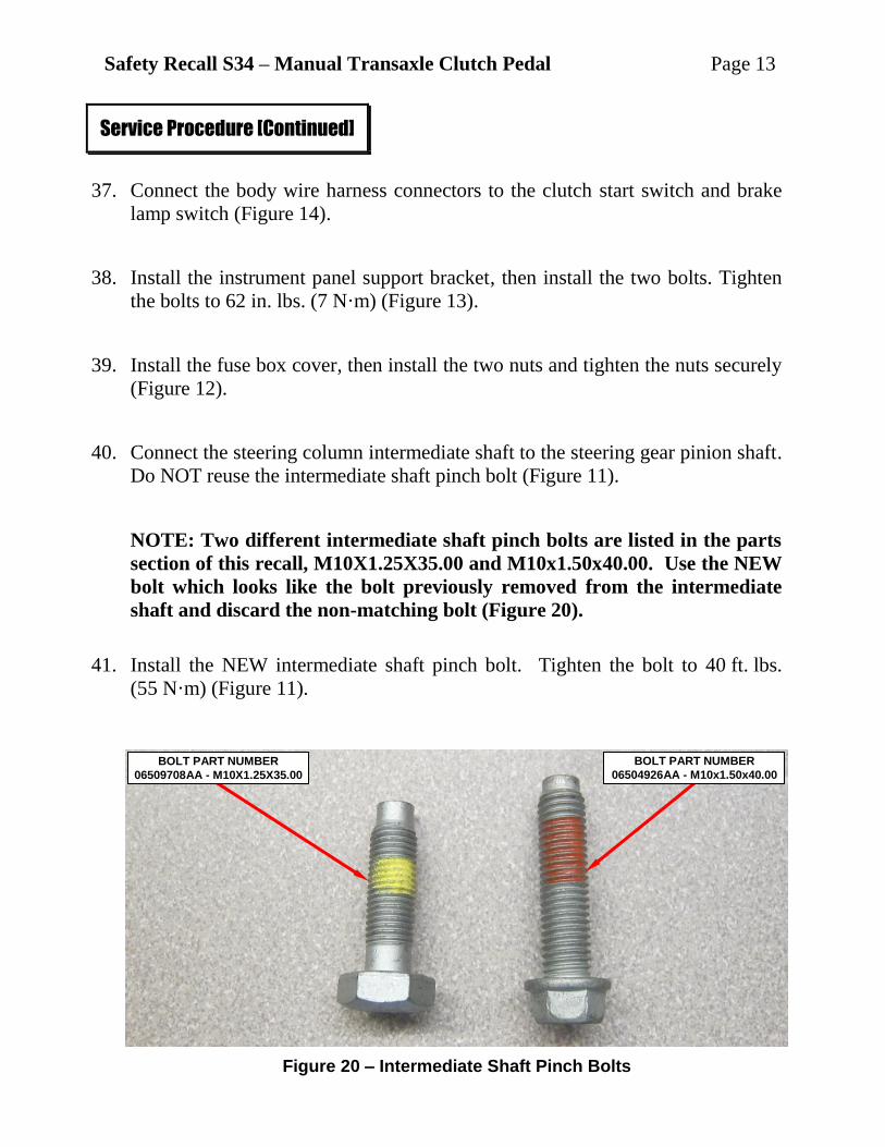
NOTE: Two different intermediate shaft pinch bolts are listed in the parts
section of this recall, M10X1.25X35.00 and M10x1.50x40.00. Use the NEW
bolt which looks like the bolt previously removed from the intermediate
shaft and discard the non-matching bolt (Figure 20).
41. Install the NEW intermediate shaft pinch bolt. Tighten the bolt to 40 ft. lbs.
(55 N·m) (Figure 11).
Service Procedure [Continued]
Figure 20 – Intermediate Shaft Pinch Bolts
BOLT PART NUMBER
06509708AA - M10X1.25X35.00
BOLT PART NUMBER
06504926AA - M10x1.50x40.00

Safety Recall S34 – Manual Transaxle Clutch Pedal Page 14
42. Install the steering column opening cover / Knee Air Bag (KAB) per the
following steps.
WARNING: To avoid serious or fatal injury on vehicles equipped with
airbags, disable the Supplemental Restraint System (SRS) before
attempting knee blocker installation. Wait two minutes after disconnecting
the vehicle battery for the system capacitor to discharge before performing
further service. This is the only sure way to disable the SRS. Failure to
take the proper precautions could result in accidental airbag deployment.
WARNING: To avoid serious or fatal injury, use extreme care to prevent
any foreign material from entering the KAB, or becoming entrapped
between the KAB cushion and the KAB trim cover. Failure to observe this
warning could result in occupant injuries upon airbag deployment.
a. Position the cover/KAB below the instrument panel in a vertical orientation
with the KAB inflator electrical connector receptacle facing upward
(Figure 10).
b. Connect the instrument panel wire harness connector to the KAB inflator
electrical connector receptacle by pressing straight in on the connector. The
connection will make an audible click noise as the connector insulator
integral latches snap into place, indicating the electrical connector is fully
engaged in its receptacle (Figure 10).
c. Carefully position the steering column opening cover/KAB unit into the
instrument panel opening (Figure 9).
d. Install the two screws that secure the column opening cover/KAB unit to
the instrument panel lower reinforcement. Tighten the screws to 53 in. lbs.
(6 N·m) (Figure 9).
e. Do not connect the negative battery cable at this time. The Supplemental
Restraint System (SRS) Verification Test detailed later in this procedure
should be performed following installation of the KAB.
Service Procedure [Continued]

Safety Recall S34 – Manual Transaxle Clutch Pedal Page 15
43. Raise and support the vehicle.
44. Connect the clutch fluid tube to the clutch master cylinder (Figure 7).
45. Lower the vehicle.
46. Install the clutch master cylinder fluid supply hose with NEW clamp to the
brake fluid reservoir (Figure 8).
47. Use special tool 10288 Hose Clamp Pliers to engage the NEW clamp securing
the clutch master cylinder fluid supply hose to the brake fluid reservoir
(Figure 8).
48. Bleed the clutch hydraulic system.
NOTE: Use Mopar brake fluid, or an equivalent quality fluid meeting
DOT 3 standards only. Use fresh, clean fluid from a sealed container at all
times.
49. Install the battery tray with one nut and two bolts. Tighten all three fasteners to
18 ft. lbs. (25 N·m) (Figure 6).
50. Engage the engine wire harness connector retainer to the battery tray (Figure 6).
51. Engage the engine wire harness retainers to the battery tray (Figure 6).
52. Install the vehicle battery into the battery tray (Figure 5).
53. Install the battery hold down retainer and tighten securely (Figure 5).
54. Install the battery thermal cover (Figure 4).
55. Connect the powertrain control module (PCM) electrical connectors (Figure 4).
56. Connect the battery positive cable terminal to the battery positive post and
tighten the terminal securely (Figure 3).
NOTE: Do NOT connect the battery negative cable at this time.
Service Procedure [Continued]

Safety Recall S34 – Manual Transaxle Clutch Pedal Page 16
57. Knee Air Bag (KAB) equipped vehicles only: Proceed to Section C.
Supplemental Restraint System (SRS) Verification Test. For vehicles
without a KAB, continue with Step 58.
58. Install the PCM ground wire to the battery negative cable terminal then connect
the negative cable terminal to the battery negative post and tighten the terminal
securely (Figure 3). If equipped with an Intelligent Battery Sensor (IBS),
connect the IBS connector after connecting the battery negative cable terminal
to the battery.
59. Install the battery positive terminal cover (Figure 2).
60. Close the vehicle hood.
61. Check for proper operation of the hydraulic clutch system.
62. Check that the clutch switch will not allow the starter to crank without the
clutch pedal depressed.
63. Check the brake lamps for proper operation.
64. Return the vehicle to the customer.
C. Supplemental Restraint System (SRS) Verification Test
NOTE: During the following test, the battery negative cable must remain
disconnected and isolated during steps 1 and 2 of the Supplemental Restraint
System (SRS) Verification Test.
NOTE: The wiTECH scan tool must be used to perform the SRS Verification
Test. The wiTECH software is required to be at the latest release before
performing the SRS Verification Test.
1. Connect the micro pod II to the vehicle data link connector located under the
instrument panel to the left of the steering column.
Service Procedure [Continued]
Safety Recall S34 – Manual Transaxle Clutch Pedal Page 17
2. Turn the ignition switch to the “ON” position then exit the vehicle and close the
doors.
3. Check to be certain that nobody is in the vehicle. Install the PCM ground wire
to the battery negative cable terminal then connect the negative cable terminal
to the vehicle battery negative post and tighten the terminal securely (Figure 3).
If equipped with an Intelligent Battery Sensor (IBS), connect the IBS connector
after connecting the battery negative cable terminal to the battery.
4. Open the wiTECH Diagnostic application.
5. Starting at the “Select Tool” screen, select the row/tool for the micro pod II
device you are using, then select “Next”.
6. Enter your “User id” and “Password”, then select “Finish”.
7. Using wiTECH, clear all DTC’s in all modules.
NOTE: Any active Diagnostic Trouble Codes (DTCs) may require an
additional key cycle from “ON” to “OFF” to change DTC status from
“active” to “stored”.
8. Turn the ignition switch to the “OFF” position for about 15 seconds, and then
back to the “ON” position. Observe the airbag indicator in the instrument
cluster.
The airbag indicator in the instrument cluster should illuminate for six to
eight seconds, and then turn off. This indicates that the SRS is
functioning normally and that the repairs are complete. Turn the ignition
to the “OFF” position then remove the micro pod II.
If the airbag indicator fails to illuminate or the indicator lamp stays ON,
there is still an active SRS fault or malfunction. Refer to the appropriate
diagnostic information to diagnose the problem.
9. Return to Step 59 of Section B. Replace Clutch/Brake Pedal Assembly.
Service Procedure [Continued]
Safety Recall S34 – Manual Transaxle Clutch Pedal Page 18
Claims for vehicles that have been serviced must be submitted on the
DealerCONNECT Claim Entry Screen located on the Service tab. Claims
submitted will be used by FCA to record recall service completions and provide
dealer payments.
Use the following labor operation numbers and time allowances:
Labor Operation Time
Number Allowance
Inspect for Clutch Pedal Travel Limiter 05-S3-41-81 0.2 hours
Inspect/Replace Clutch/Brake 05-S3-41-82 1.4 hours
Pedal Assembly
Add the cost of the recall parts package plus applicable dealer allowance to your
claim.
NOTE: See the Warranty Administration Manual, Recall Claim Processing
Section, for complete recall claim processing instructions.
To view this notification on DealerCONNECT, select “Global Recall System” on
the Service tab, then click on the description of this notification.
Completion Reporting and Reimbursement
Dealer Notification

Safety Recall S34 – Manual Transaxle Clutch Pedal Page 19
All involved vehicle owners known to FCA are being notified of the service
requirement by first class mail. They are requested to schedule appointments for this
service with their FIAT studios. A generic copy of the owner letter is attached.
Enclosed with each owner letter is an Owner Notification postcard to allow owners
to update our records if applicable.
All involved vehicles have been entered into the DealerCONNECT Global Recall
System (GRS) and Vehicle Information Plus (VIP) for dealer inquiry as needed.
GRS provides involved dealers with an updated VIN list of their incomplete
vehicles. The owner’s name, address and phone number are listed if known.
Completed vehicles are removed from GRS within several days of repair claim
submission.
To use this system, click on the “Service” tab and then click on “Global Recall
System.” Your dealer’s VIN list for each recall displayed can be sorted by: those
vehicles that were unsold at recall launch, those with a phone number, city, zip
code, or VIN sequence.
Dealers must perform this repair on all unsold vehicles before retail delivery.
Dealers should also use the VIN list to follow up with all owners to schedule
appointments for this repair.
Recall VIN lists may contain confidential, restricted owner name and address information that
was obtained from the Department of Motor Vehicles of various states. Use of this information
is permitted for this recall only and is strictly prohibited from all other use.
If you have any questions or need assistance in completing this action, please
contact your Service and Parts District Manager.
Customer Services / Field Operations
FCA US LLC
Owner Notification and Service Scheduling
Vehicle Lists, Global Recall System, VIP and Dealer Follow Up
Additional Information
_________________________________________________________________________________________________________________________________
IMPORTANT SAFETY RECALL S34 / NHTSA 16V-302
This notice applies to your vehicle (VIN: xxxxxxxxxxxxxxxxx).
This notice is sent to you in accordance with the requirements of the National Traffic and Motor Vehicle Safety Act.
Dear: (Name)
FCA has decided that a defect, which relates to motor vehicle safety, exists in certain 2012 through 2016 model
year FIAT 500 vehicles equipped with a manual transaxle.
The problem is... The clutch cover diaphragm spring on your vehicle may fatigue and/or fracture. A
failed clutch cover diaphragm spring may result in the inability to disengage the clutch,
shift gears and the potential for a loss of motive power. The inability to disengage the
clutch, shift gears and/or loss of motive power could cause a crash without warning.
What your studio
will do... FCA will repair your vehicle free of charge. To do this, your FIAT studio will install a
clutch pedal assembly with pedal travel limiter and a clutch pedal switch. The work will
take about 2 hours to complete. However, additional time may be necessary depending on
service schedules.
What you must do
to ensure your
safety...
Simply contact your FIAT studio, at your convenience, to schedule a service appointment.
Your FIAT studio will collect the necessary information to ensure that the appropriate parts
are available so your service can be completed in a timely manner. Although not required,
we recommend bringing this letter with you to your FIAT studio, when you bring your
vehicle in for this service.
If you need help... Please contact the FCA US Recall Information Center at either recalls.mopar.com or phone
1-800-853-1403.
Please help us update our records by filling out the attached prepaid postcard if any of the conditions listed on the
card apply to you or your vehicle. If you have further questions go to recalls.mopar.com.
If you have already experienced this specific condition and have paid to have it repaired, you may visit
www.fcarecallreimbursement.com to submit your reimbursement request online or you can mail your original
receipts and proof of payment to the following address for reimbursement consideration: FCA Customer
Assistance, P.O. Box 21-8004, Auburn Hills, MI 48321-8007, Attention: Recall Reimbursement. Once we
receive and verify the required documents, reimbursement will be sent to you within 60 days. If you’ve had
previous repairs and/or reimbursement you may still need to have the recall repair performed on your vehicle.
If your studio fails or is unable to remedy this defect without charge and within a reasonable time, you may submit a
written complaint to the Administrator, National Highway Traffic Safety Administration, 1200 New Jersey Ave.,
S.E., Washington, DC 20590, or you can call the toll-free Vehicle Safety Hotline at 1-888-327-4236
(TTY 1-800-424-9153), or go to safercar.gov.
We're sorry for any inconvenience, but we are sincerely concerned about your safety. Thank you for your attention
to this important matter.
Customer Services / Field Operations
FCA US LLC
Note to lessors receiving this recall: Federal regulation requires that you forward this recall notice to the lessee within 10 days.
MANUAL TRANSAXLE CLUTCH PEDAL