safety profile specification epsg working draft proposal 304 v1.4.0 epsg wdp 304 v-1-4-0.docx 3/191...
TRANSCRIPT

openSAFETY
Safety Profile Specification
EPSG Working Draft Proposal 304 V1.4.0
EPSG WDP 304 V-1-4-0.docx 1/191
EPSG Working Draft Proposal 304 1
openSAFETY 2
Safety Profile Specification 3
Version 1.4.0 4
© EPSG 5
(Ethernet POWERLINK Standardisation Group) 6
2013 7
8

openSAFETY
Safety Profile Specification
EPSG Working Draft Proposal 304 V1.4.0
EPSG WDP 304 V-1-4-0.docx 2/191
9
10
11
12
13
14
EPSG (Ethernet POWERLINK Standardisation Group) 15
16
17
POWERLINK-Office of the EPSG 18
Kurfuerstenstrasse 112 19
D-10787 Berlin 20
Germany 21
22
23
Phone +49.30.850885-29 24
Fax +49.30.850885-86 25
www.ethernet-powerlink.org 27
openSAFETY
Safety Profile Specification
EPSG Working Draft Proposal 304 V1.4.0
EPSG WDP 304 V-1-4-0.docx 3/191
Disclaimer 28
Use of this EPSG Standard is wholly voluntary. The EPSG disclaims liability for any personal injury, 29
property or other damage, of any nature whatsoever, whether special, indirect, consequential, or 30
compensatory, directly or indirectly resulting from the publication, use of, or reliance upon this, or any 31
other EPSG Standard document. 32
The EPSG does not warrant or represent the accuracy or content of the material contained herein, 33
and expressly disclaims any express or implied warranty, including any implied warranty of 34
merchantability or fitness for a specific purpose, or that the use of the material contained herein is free 35
from patent infringement. EPSG Standards documents are supplied “AS IS”. 36
The existence of an EPSG Standard does not imply that there are no other ways to produce, test, 37
measure, purchase, market, or provide other goods and services related to the scope of the EPSG 38
Standard. Furthermore, the viewpoint expressed at the time a standard is approved and issued is 39
subject to change brought about through developments in the state of the art and comments received 40
from users of the standard. Users are cautioned to check to determine that they have the latest edition 41
of any EPSG Standard. 42
In publishing and making this document available, the EPSG is not suggesting or rendering 43
professional or other services for, or on behalf of, any person or entity. Nor is the EPSG undertaking to 44
perform any duty owed by any other person or entity to another. Any person utilizing this, and any 45
other EPSG Standards document, should rely upon the advice of a competent professional in 46
determining the exercise of reasonable care in any given circumstances. 47
Interpretations: Occasionally questions may arise regarding the meaning of portions of standards as 48
they relate to specific applications. When the need for interpretations is brought to the attention of the 49
EPSG, the group will initiate action to prepare appropriate responses. Since EPSG Standards 50
represent a consensus of concerned interests, it is important to ensure that any interpretation has also 51
received the concurrence of a balance of interests. For this reason, the EPSG and its members are 52
not able to provide an instant response to interpretation requests except in those cases where the 53
matter has previously received formal consideration. 54
Comments for revision of EPSG Standards are welcome from any interested party, regardless of 55
membership affiliation with the EPSG. Suggestions for changes in documents should be in the form of 56
a proposed change of text, together with appropriate supporting comments. Comments on standards 57
and requests for interpretations should be addressed to: 58
59
POWERLINK-Office of the EPSG 60
Kurfuerstenstrasse 112 61
D-10787 Berlin 62
Germany. 63
64
Patent notice 65
66
Attention is called to the possibility that implementation of this standard may require use of subject 67
matter covered by patent rights. By publication of this standard, no position is taken with respect to the 68
existence or validity of any patent rights in connection therewith. The EPSG shall not be responsible 69
for identifying patents for which a license may be required by an EPSG standard or for conducting 70
inquiries into the legal validity or scope of those patents that are brought to its attention. 71

openSAFETY
Safety Profile Specification
EPSG Working Draft Proposal 304 V1.4.0
EPSG WDP 304 V-1-4-0.docx 4/191
Contribution 72
The following persons contributed to this document: 73
Beckmann, Guido Lenze Drive Systems GmbH 74
Boast, Gerry Baldor Electric Company 75
Enzinger, Thomas Bernecker + Rainer Industrie-Elektronik Ges.m.b.H. 76
Etschberger, Konrad IXXAT Automation GmbH 77
Geßler, Dieter IXXAT Automation GmbH 78
Graf, Anton Bernecker + Rainer Industrie-Elektronik Ges.m.b.H. 79
Hog, Günter Parker Hannifin GmbH 80
Kaufleitner, Franz Bernecker + Rainer Industrie-Elektronik Ges.m.b.H. 81
Kieviet, Michael innotec GmbH 82
Knall, Roland Bernecker + Rainer Industrie-Elektronik Ges.m.b.H. 83
Matejka, Franz Bernecker + Rainer Industrie-Elektronik Ges.m.b.H. 84
Pill, Hans LARsys-Automation GmbH 85
Potier, Stephane Bernecker + Rainer Industrie-Elektronik Ges.m.b.H. 86
Sasse, Volker KW-Software GmbH 87
Sauer, Bernhard Eckelmann AG 88
Wratil, Peter innotec GmbH 89
90
Special Thanks to 91
Gall, Heinz TÜV Rheinland Group 92
Janoschek, Erich TÜV Rheinland Group 93
Greil, Günter TÜV Süd 94
Neumann, Guido TÜV Süd 95
Supavatanakul, Peerasan TÜV Süd 96
Tschürtz, Hans FH Campus Wien 97
Gerstinger, Andreas FH Campus Wien 98
Kahn, Daniela FH Campus Wien 99
Sebron, Walter FH Campus Wien 100
openSAFETY
Safety Profile Specification
EPSG Working Draft Proposal 304 V1.4.0
EPSG WDP 304 V-1-4-0.docx 5/191
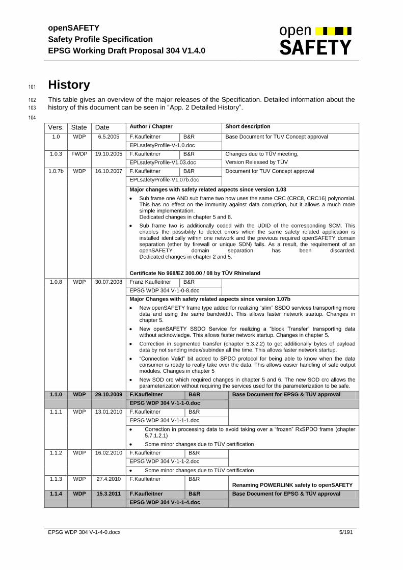
History 101
This table gives an overview of the major releases of the Specification. Detailed information about the 102
history of this document can be seen in “App. 2 Detailed History”. 103
104
Vers. State Date Author / Chapter Short description
1.0 WDP 6.5.2005 F.Kaufleitner B&R Base Document for TUV Concept approval
EPLsafetyProfile-V-1.0.doc
1.0.3 FWDP 19.10.2005 F.Kaufleitner B&R Changes due to TÜV meeting,
Version Released by TÜV EPLsafetyProfile-V1.03.doc
1.0.7b WDP 16.10.2007 F.Kaufleitner B&R Document for TUV Concept approval
EPLsafetyProfile-V1.07b.doc
Major changes with safety related aspects since version 1.03
Sub frame one AND sub frame two now uses the same CRC (CRC8, CRC16) polynomial. This has no effect on the immunity against data corruption, but it allows a much more simple implementation. Dedicated changes in chapter 5 and 8.
Sub frame two is additionally coded with the UDID of the corresponding SCM. This enables the possibility to detect errors when the same safety related application is installed identically within one network and the previous required openSAFETY domain separation (ether by firewall or unique SDN) fails. As a result, the requirement of an openSAFETY domain separation has been discarded. Dedicated changes in chapter 2 and 5.
Certificate No 968/EZ 300.00 / 08 by TÜV Rhineland
1.0.8 WDP 30.07.2008 Franz Kaufleitner B&R
EPSG WDP 304 V-1-0-8.doc
Major Changes with safety related aspects since version 1.07b
New openSAFETY frame type added for realizing “slim” SSDO services transporting more data and using the same bandwidth. This allows faster network startup. Changes in chapter 5.
New openSAFETY SSDO Service for realizing a “block Transfer” transporting data without acknowledge. This allows faster network startup. Changes in chapter 5.
Correction in segmented transfer (chapter 5.3.2.2) to get additionally bytes of payload data by not sending index/subindex all the time. This allows faster network startup.
“Connection Valid” bit added to SPDO protocol for being able to know when the data consumer is ready to really take over the data. This allows easier handling of safe output modules. Changes in chapter 5
New SOD crc which required changes in chapter 5 and 6. The new SOD crc allows the parameterization without requiring the services used for the parameterization to be safe.
1.1.0 WDP 29.10.2009 F.Kaufleitner B&R Base Document for EPSG & TÜV approval
EPSG WDP 304 V-1-1-0.doc
1.1.1 WDP 13.01.2010 F.Kaufleitner B&R
EPSG WDP 304 V-1-1-1.doc
Correction in processing data to avoid taking over a “frozen” RxSPDO frame (chapter 5.7.1.2.1)
Some minor changes due to TÜV certification
1.1.2 WDP 16.02.2010 F.Kaufleitner B&R
EPSG WDP 304 V-1-1-2.doc
Some minor changes due to TÜV certification
1.1.3 WDP 27.4.2010 F.Kaufleitner B&R Renaming POWERLINK safety to openSAFETY
1.1.4 WDP 15.3.2011 F.Kaufleitner B&R Base Document for EPSG & TÜV approval
EPSG WDP 304 V-1-1-4.doc

openSAFETY
Safety Profile Specification
EPSG Working Draft Proposal 304 V1.4.0
EPSG WDP 304 V-1-4-0.docx 6/191
Major Changes with safety related aspects since version 1.1.3
Due to IEC 61508:ED2, security aspects updated: 2.3.2.1
CRC polynomial for frames with more than 8 byte payload changed to 0xBAAD: 5.1.1.8
Unclear specification elements within block transfer corrected: 5.3.1, 5.3.2.3, 5.3.2.7, 5.3.2.8
Abort code corrected: 5.3.2.9
Calculation for residual error probability updated: 8.1, 8.2, 8.3
New optional features:
o Number of Retries for Reset Guarding: 5.6.4, 5.6.4.6, 5.6.4.7, 5.7.6.2
o User Parameter (writeable at any time): 5.6.4, 5.6.4.18, 5.7.4
1.4.0 WDP 13.03.2013 R.Knall B&R
EPSG WDP 304 V-1-4-0.docx
Document version adapted according to the numbering for the openSAFETY certification set
Rearrange chapter “Parameterization Interface of SOD”
Document corrections since version 1.1.4
o Corrected calculation information for the basic and slim ssdo openSAFETY frames: 5.1.1.1
o Text changes to clarify meaning: 5.1.1.5, 5.2.1, 5.3, 5.3.1, 5.3.2.6, 5.6.4.6, 5.6.4.7, 5.6.4.8, 5.6.4.22, 5.7.10
o EPLv2 changed to Fieldbus, EPLsafety changed to openSAFETY: 7.2
o Corrected number of entries for SOD objects: 5.6.4.11, 5.6.4.12, 5.6.4.15, 5.6.4.20
o Corrected package diagram, to correctly identify timestamp instead of crc: 5.4.3.2
Major Changes with safety related aspects since version 1.1.4
openSAFETY Stack Version identification
o 0x1018 – Adding sub-index 0x08 and 0x09 to identify stack version: 5.6.4.8
o Process definition Fig. 77
Error handling improvements
o 0xC400 – Changing the numbering of the module status: 5.6.4.20
o Introducing object for collecting error statistics for a stack implementation: 5.6.4.4
Clarified wording, that SLIM SSDOs are not allowed for user parameter: 5.6.4.18
No longer part of SOD CRC due to no relevance for SN:
o 0x101B - SCM Parameters: 5.6.4.11
o 0x1201 – SSDO Communication Parameters: 5.6.4.13
o 0x1202 – SNMT Communication Parameters: 5.6.4.14
Additional parameter Sets :
o Description of error group/code handling with additional parameters: 5.4.3.2.1
o 0xC400-0xC4FE – Ability switch for a module to accept additional parameters: 5.6.4.20
o 0xE400-0xE4FE – SOD object to store additional parameter sets on SN: 5.6.4.23
o Adapting SN Power Up state diagram to implement additional parameter checks: 5.7.6.2, 5.7.6.3

openSAFETY
Safety Profile Specification
EPSG Working Draft Proposal 304 V1.4.0
EPSG WDP 304 V-1-4-0.docx 7/191
Content 105
Disclaimer 3 106
Contribution 4 107
History 5 108
Content 7 109
Tables 12 110
Figures 15 111
Equations 17 112
Definitions and Abbreviations 18 113
References 20 114
1 Introduction 21 115
1.1 Referenced Standards 21 116
1.2 openSAFETY key features 21 117
1.3 Integration 22 118
1.4 Modular Machines 23 119
2 Modeling 24 120
2.1 Reference Model 24 121
2.2 Communication Model 25 122
2.3 openSAFETY Topology 26 123
2.3.1 openSAFETY Node (SN) 27 124
2.3.2 openSAFETY Domain (SD) 27 125
2.3.2.1 openSAFETY Domain Protection 28 126
2.3.2.2 openSAFETY Domain Separation 28 127
2.3.3 openSAFETY Domain Gateway (SDG) 29 128
2.3.4 openSAFETY Configuration Manager (SCM) 29 129
3 openSAFETY Life Cycle Model 30 130
3.1 Concept, Planning and Implementation 30 131
3.1.1 Application Layout 30 132
3.1.2 Programming and Parameterization 30 133
3.1.2.1 Automatic Configuration Mode (ACM) 31 134
3.1.2.2 Manual Configuration Mode (MCM) 31 135
3.2 Commissioning 31 136
3.2.1 Installation 31 137
3.2.2 Configuration Setup 32 138
3.2.2.1 Configuration Setup using ACM 32 139
3.2.2.2 Configuration Setup using MCM 32 140
3.2.3 Verification 32 141
3.3 Operation Terms 33 142
3.3.1 Transfer of Safety related Data 33 143
3.3.2 Time Synchronization and Validation 33 144
3.3.3 Life Guarding 33 145
3.3.4 Startup after Power up or Reset 34 146
3.3.5 Recover from Network Failure 34 147
3.4 Maintenance Terms 34 148
3.4.1 Diagnostic Information 34 149
3.4.2 Replace safety related devices 34 150
3.4.2.1 SN Replacement 34 151
3.4.2.2 Replacement of SN running the SCM 34 152
3.4.3 Modification 34 153
openSAFETY
Safety Profile Specification
EPSG Working Draft Proposal 304 V1.4.0
EPSG WDP 304 V-1-4-0.docx 8/191
3.4.4 Machine part changing 35 154
3.4.5 Firmware update of safety related nodes 35 155
3.4.6 Machine check due to service interval 35 156
4 Non safe Communication Layer 36 157
4.1 Requirements to Data Transport 36 158
4.1.1 Transport of SPDO 36 159
4.1.2 Transport of SSDO 36 160
4.2 Representation of Diagnostic Data 36 161
4.3 Safety Domain Protection and Separation 36 162
5 openSAFETY Layer 37 163
5.1 openSAFETY Data Services 37 164
5.1.1 Structure of openSAFETY Frame 37 165
5.1.1.1 Basic openSAFETY Frame 37 166
5.1.1.2 Slim SSDO openSAFETY Frame 39 167
5.1.1.3 Address Field (ADR) 40 168
5.1.1.4 ID Field (Frame Identification) 41 169
5.1.1.5 Length Field (LE) 42 170
5.1.1.6 Consecutive Time Field (CT) 42 171
5.1.1.7 Payload Data Field (DB0 to DBn) 42 172
5.1.1.8 Cyclic Redundancy Check Field (CRC-8 / CRC-16) 42 173
5.1.1.8.1 Rules for CRC generation: 42 174
5.1.1.9 Time Request Address (TADR) 43 175
5.1.1.10 a SN Time Request Distinctive Number Field (TR) 43 176
5.1.1.11 UDID of SCM coding (UDID of SCM) 43 177
5.2 Safety Process Data Object (SPDO) 44 178
5.2.1 SPDO Frame Types 44 179
5.2.2 Data Only Frame 45 180
5.2.3 Data with Time Request Frame 46 181
5.2.4 Data with Time Response Frame 47 182
5.3 Safety Service Data Object (SSDO) 48 183
5.3.1 SSDO Frame Types 48 184
5.3.2 SSDO Services and Protocols 50 185
5.3.2.1 SSDO Download Initiate 52 186
5.3.2.2 SSDO Download Segment 53 187
5.3.2.3 SSDO Block Download Initiate 54 188
5.3.2.4 SSDO Block Download Segment 55 189
5.3.2.5 SSDO Upload Initiate 56 190
5.3.2.6 SSDO Upload Segment 57 191
5.3.2.7 SSDO Block Upload Initiate 57 192
5.3.2.8 SSDO Block Upload Segment 59 193
5.3.2.9 SSDO Abort 60 194
5.4 Safety Network Management (SNMT) 62 195
5.4.1 SNMT Frame Types 62 196
5.4.2 SNMT Services and Protocols 63 197
5.4.2.1 UDID Request 63 198
5.4.2.2 SADR assignment 64 199
5.4.2.3 Reset node guarding time 65 200
5.4.3 SNMT Extended Services 66 201
5.4.3.1 SN set to preoperational 67 202
5.4.3.2 SN set to operational 68 203
5.4.3.2.1 Additional Parameter 70 204
5.4.3.3 SNMT SN ack 71 205
5.4.3.4 SCM set to stop 72 206
5.4.3.5 SCM set to operational 73 207
5.4.3.6 Node Guarding 74 208

openSAFETY
Safety Profile Specification
EPSG Working Draft Proposal 304 V1.4.0
EPSG WDP 304 V-1-4-0.docx 9/191
5.4.3.7 Additional SADR assignment 75 209
5.4.3.8 UDID of SCM assignment 76 210
5.5 Data Types and Encoding Rules 77 211
5.5.1 General Description 77 212
5.5.2 Data Type Definitions 77 213
5.5.3 Bit Sequences 78 214
5.5.3.1 Definition of Bit Sequences 78 215
5.5.3.2 Transfer Syntax for Bit Sequences 79 216
5.5.4 Basic Data Types 79 217
5.5.4.1 NIL 79 218
5.5.4.2 Boolean 79 219
5.5.4.3 Void 80 220
5.5.4.4 Unsigned Integer 80 221
5.5.4.5 Signed Integer 81 222
5.5.4.6 Floating Point Numbers 82 223
5.5.5 Compound Data Types 83 224
5.5.6 Extended Data Types 83 225
5.5.6.1 Octet String 83 226
5.5.6.2 Visible String 84 227
5.5.6.3 Unicode String 84 228
5.5.6.4 Domain 84 229
5.6 Object Dictionary (SOD) 85 230
5.6.1 Data Type Entry Specification 85 231
5.6.2 Object Dictionary Entry Definition 86 232
5.6.2.1 Sub-Index Definition 89 233
5.6.3 Data Type Entry Specification 90 234
5.6.3.1 Static Data Types 91 235
5.6.3.2 Complex Data Types 91 236
5.6.4 Object Description 91 237
5.6.4.1 Object 1001h: Error Register 95 238
5.6.4.2 Object 1002h: Manufacturer status register 95 239
5.6.4.3 Object 1003h: Pre defined error field 96 240
5.6.4.4 Object 1004h: Error statistics 97 241
5.6.4.5 Object 100Ch: Life Guarding 99 242
5.6.4.6 Object 100Dh: Number of Retries for Reset Guarding 99 243
5.6.4.7 Object 100Eh: Refresh interval of Reset Guarding 100 244
5.6.4.8 Object 1018h: Device Vendor Information 100 245
5.6.4.8.1 Manufacturer Revision number 102 246
5.6.4.8.2 Calculation of the parameter checksum 102 247
5.6.4.8.3 openSAFETY stack version 102 248
5.6.4.9 Object 1019h: Unique Device ID 103 249
5.6.4.10 Object 101Ah: Parameter Download 103 250
5.6.4.10.1 Additional Parameter Header 104 251
5.6.4.11 Object 101Bh: SCM Parameters 104 252
5.6.4.12 Object 1200h: Common Communication Parameter 105 253
5.6.4.13 Object 1201h: SSDO Communication Parameter 106 254
5.6.4.14 Object 1202h: SNMT Communication Parameter 107 255
5.6.4.15 Object 1400h –17FEh: RxSPDO Communication Par. 108 256
5.6.4.16 Object 1800h – 1BFEh: RxSPDO Mapping Parameter 110 257
5.6.4.17 Object 1C00h – 1FFEh: TxSPDO Communication Par. 111 258
5.6.4.18 Object 2800h – 2FFFh: User Par. (writeable at any time) 111 259
5.6.4.19 Object C000h – C3FEh: TxSPDO Mapping Parameter 111 260
5.6.4.20 Object C400h – C7FEh: SADR-DVI List 113 261
5.6.4.21 Object C801h – CBFFh: Additional SADR List 116 262
5.6.4.22 Object CC01h – CFFFh: SADR-UDID List 118 263
5.6.4.23 Object E400h – E7FEh: Additional Parameter List 118 264
5.6.5 Safety related PDO Mapping 120 265
openSAFETY
Safety Profile Specification
EPSG Working Draft Proposal 304 V1.4.0
EPSG WDP 304 V-1-4-0.docx 10/191
5.6.6 Transmit SPDOs 120 266
5.6.7 Receive SPDOs 121 267
5.6.8 SPDO Mapping Parameter 121 268
5.6.9 SPDO Mapping Example 122 269
5.6.10 SPDO Error Handling 124 270
5.7 State - / Sequence Diagrams 125 271
5.7.1 Safety Process Data Object (SPDO) 125 272
5.7.1.1 Safety Process Data Object Producer (TxSPDO) 125 273
5.7.1.2 Safety Process Data Object Consumer (RxSPDO) 126 274
5.7.1.2.1 Process Data 128 275
5.7.2 Time Synchronization and Validation 129 276
5.7.2.1 Time Synchronization 130 277
5.7.2.2 Time Validation 132 278
5.7.2.3 Time Synchronization Operation 134 279
5.7.2.4 Time Synchronization Frequency 137 280
5.7.2.5 Time Synchronization Producer 138 281
5.7.2.6 Time Synchronization Consumer 139 282
5.7.3 Safety Service Data Object (SSDO) 141 283
5.7.3.1 SSDO Client 141 284
5.7.3.2 SSDO Server 142 285
5.7.4 SOD Access 143 286
5.7.4.1 SOD Access (expedited) 143 287
5.7.4.2 SOD Download Access with segmentation 144 288
5.7.4.2.1 Client state diagram 144 289
5.7.4.2.2 Server state diagram 146 290
5.7.4.3 SOD Block Download Access 148 291
5.7.4.3.1 Client state diagram 148 292
5.7.4.3.2 Server state diagram 150 293
5.7.5 Safety Network Management Object (SNMT) 152 294
5.7.5.1 SNMT Master 152 295
5.7.5.2 SNMT Slave 153 296
5.7.6 SN Power Up 154 297
5.7.6.1 States and Communication Object Relation 154 298
5.7.6.2 Pre-Operational 155 299
5.7.6.3 Additional Parameters 157 300
5.7.6.4 Operational 158 301
5.7.7 SN Power Down 159 302
5.7.8 SN Recovery after Restart / Error 159 303
5.7.9 SCM Power Up 160 304
5.7.9.1 States and Communication Object Relation 160 305
5.7.9.2 Operational 161 306
5.7.10 Safety Address Verification 163 307
5.7.11 Commissioning Mode 164 308
5.7.12 Handle Single UDID Mismatch 165 309
5.7.13 Verify Parameters 167 310
5.7.14 Handle SN Version 169 311
5.7.15 Activate SN 171 312
5.7.16 Module Exchange 172 313
6 Parameterization Interface of SOD 173 314
6.1 Configuration of an SD 173 315
6.2 Parameter check mechanism 173 316
7 openSAFETY Conformance 174 317
7.1 openSAFETY Change Management 174 318
7.2 Certification flow for openSAFETY devices 175 319
8 Safety Requirement Specification 176 320

openSAFETY
Safety Profile Specification
EPSG Working Draft Proposal 304 V1.4.0
EPSG WDP 304 V-1-4-0.docx 11/191
8.1 CRC error detection capabilities 176 321
8.2 Failure detection for parameterization services 176 322
8.3 Failure detection for data transfer services 176 323
8.3.1 Systematic failures 177 324
8.3.2 Stochastic errors 177 325
8.3.2.1 Calculation of residual error probability 178 326
8.3.2.2 Assumed bit error rate 180 327
8.3.2.3 Residual error probability 181 328
8.4 Summary 182 329
8.5 Safety requirements 182 330
8.5.1 Data Transfer with SPDO, SSDO services 182 331
8.5.2 Data Transfer using SLIM SSDO Services 182 332
8.6 Safety architecture 182 333
App. 1 CRC Coding Example 185 334
App. 2 Detailed History 189 335
336
337
openSAFETY
Safety Profile Specification
EPSG Working Draft Proposal 304 V1.4.0
EPSG WDP 304 V-1-4-0.docx 12/191
Tables 338
Tab. 1 Basic openSAFETY frame 38 339
Tab. 2 Slim SSDO openSAFETY frame 39 340
Tab. 3 Avaiable frame types 41 341
Tab. 4 Used ID field combinations 41 342
Tab. 5 Request / response identification 41 343
Tab. 6 Relation between Length Field and used CRC 42 344
Tab. 7 CRC Polynoms 42 345
Tab. 8 SPDO Frame Types (ID Field, Bits 3,4) 44 346
Tab. 9 SPDO Data Only Frame 45 347
Tab. 10 SPDO with data and time request 46 348
Tab. 11 SPDO with data and time response 47 349
Tab. 12 SSDO Frame Types (ID Field, Bits 2,3,4) 48 350
Tab. 13 SOD Access Command (SACmd) – Bit coding 49 351
Tab. 14 SSDO Download Initiate Protocol 52 352
Tab. 15 SSDO Download Segment Protocol 53 353
Tab. 16 SSDO Block Download Initiate Protocol 54 354
Tab. 17 SSDO Block Download Segment Protocol 55 355
Tab. 18 SSDO Upload Initiate Protocol 56 356
Tab. 19 SSDO Upload Segment Protocol 57 357
Tab. 20 SSDO Block Upload Initiate Protocol 58 358
Tab. 21 SSDO Block Upload Segment Protocol 59 359
Tab. 22 SSDO Abort Protocol 60 360
Tab. 23 SSDO abort codes 61 361
Tab. 24 SNMT Frame Types (ID Field, Bits 2,3 and 4) 62 362
Tab. 25 SNMT UDID Request 63 363
Tab. 26 SNMTSADR Assignment 64 364
Tab. 27 SNMT SN reset guarding SCM 65 365
Tab. 28 SNMT Frame Types specified by DB0 (SNMTCmd) 66 366
Tab. 29 SNMT SN put to Preoperational State 67 367
Tab. 30 SNMT set to Operational state 69 368
Tab. 31 SNMT_SN_FAIL Error Group 70 369
Tab. 32 SNMT_SN_FAIL Error Code 70 370
Tab. 33 SNMT_SN_FAIL Error Code 70 371
Tab. 34 SNMT SN ack 71 372
Tab. 35 SNMT SCM put to stop state 72 373
Tab. 36 SNMT SCM put to operational state 73 374
Tab. 37 SNMT SCM guard SN 74 375
Tab. 38 SNMT additional SADR assignment 75 376
Tab. 39 UDID of SCM assignment 76 377
Tab. 40 Transfer Syntax for Bit Sequences 79 378
Tab. 41 Transfer syntax for data type UNSIGNEDn 80 379
Tab. 42 Object Dictionary Data Types 85 380
Tab. 43 Object type definitions 86 381
openSAFETY
Safety Profile Specification
EPSG Working Draft Proposal 304 V1.4.0
EPSG WDP 304 V-1-4-0.docx 13/191
Tab. 44 Access Attributes for Data Objects 87 382
Tab. 45 SPDO Mapping Attributes for Data Objects 88 383
Tab. 46 Static Data Type Object Definition Example 88 384
Tab. 47 Complex Data Type Object Definition Example 88 385
Tab. 48 NumberOf Entries Sub-Index Description Example 89 386
Tab. 49 Record Type Object Sub-Index Description Example 89 387
Tab. 50 Array Type Object Sub-Index Description Example 90 388
Tab. 51 Structure of Sub-Index FFh 90 389
Tab. 52 Complex Data Type Description Example 91 390
Tab. 53 Standard Objects 93 391
Tab. 54 Structure of the Error Register 95 392
Tab. 55 Structure of Revision number 102 393
Tab. 56 Structure of openSAFETY version number 102 394
Tab. 57 Format for parameter transmission in 0x101a 103 395
Tab. 58 Format for additional parameter header 104 396
Tab. 59 Structure of SPDO mapping entry 121 397
Tab. 60 Mapping example table 1 122 398
Tab. 61 Mapping example table 2 122 399
Tab. 62 Mapping example table 3 123 400
Tab. 63 Mapping example table 4 123 401
Tab. 64 Mapping example table 5 123 402
Tab. 65 Mapping example table 6 123 403
Tab. 66 Mapping example table 7 124 404
Tab. 67 SPDO communication producer item description 125 405
Tab. 68 SPDO communication producer state description 126 406
Tab. 69 SPDO communication consumer item description 127 407
Tab. 70 SPDO communication consumer state description 127 408
Tab. 71 SPDO communication consumer telegram validation item description 128 409
Tab. 72 SPDO communication consumer telegram validation state description 129 410
Tab. 73 Time synchronization item description 131 411
Tab. 74 Time validation item description 133 412
Tab. 75 Extended Time synchronization item description 136 413
Tab. 76 Time synchronization Frequency item description 137 414
Tab. 77 Time synchronization producer item description 138 415
Tab. 78 Time synchronization producer state description 138 416
Tab. 79 Time synchronization consumer item description 140 417
Tab. 80 Time synchronization consumer state description 140 418
Tab. 81 SSDO client item description 141 419
Tab. 82 SSDO client state description 141 420
Tab. 83 SSDO server state description 142 421
Tab. 84 SOD Access item description 143 422
Tab. 85 Segmented SOD Access client item description 145 423
Tab. 86 Segmented SOD Access client state description 145 424
Tab. 87 Segmented SOD Access server item description 146 425
Tab. 88 Segmented SOD Access server state description 147 426
Tab. 89 SOD Block Download Access client item description 149 427
openSAFETY
Safety Profile Specification
EPSG Working Draft Proposal 304 V1.4.0
EPSG WDP 304 V-1-4-0.docx 14/191
Tab. 90 SOD Block Download Access client state description 149 428
Tab. 91 SOD Block Download Access server item description 150 429
Tab. 92 SOD Block Download Access server state description 151 430
Tab. 93 SNMT master item description 152 431
Tab. 94 SNMT master state description 152 432
Tab. 95 SNMT slave state description 153 433
Tab. 96 SN power up state description 154 434
Tab. 97 State and communication object relation 154 435
Tab. 98 SN Pre-Operational state item description 156 436
Tab. 99 SN Pre-Operational state description 156 437
Tab. 100 Additional parameter download state description 158 438
Tab. 101 SN Operational state item description 159 439
Tab. 102 SN Operational state description 159 440
Tab. 103 SCM power up state description 160 441
Tab. 104 State and communication object relation 160 442
Tab. 105 SCM operational state item description 162 443
Tab. 106 SCM operational state description 162 444
Tab. 107 Safety address verification item description 164 445
Tab. 108 Safety address verification state description 164 446
Tab. 109 Handle UDID mismatch state description 166 447
Tab. 110 Parameter verification state description 168 448
Tab. 111 Version verification state description 170 449
Tab. 112 SN activation state description. 171 450
Tab. 113 CRC Polynomials and characteristic 176 451
Tab. 114 openSAFETY failure measures 177 452
Tab. 115 Overview of Frame elements and applied measures against stochastic errors 178 453
Tab. 116 Residual error probability calculation, symbols and terms 179 454
Tab. 117 residual error probability and the maximum message rate per second to claim SIL 3 182 455
456
457

openSAFETY
Safety Profile Specification
EPSG Working Draft Proposal 304 V1.4.0
EPSG WDP 304 V-1-4-0.docx 15/191
Figures 458
Fig. 1. Integration of openSAFETY into the IT infrastructure of end customer 22 459
Fig. 2. Reference Model 24 460
Fig. 3. Characteristic producer / consumer communication 25 461
Fig. 4. Extended producer / consumer communication 25 462
Fig. 5. Server Client communication 26 463
Fig. 6. openSAFETY Topology Schema 26 464
Fig. 7. openSAFETY Domain Protection 28 465
Fig. 8. openSAFETY Domain Separation 28 466
Fig. 9. openSAFETY data flow example 33 467
Fig. 10. Data format of a basic openSAFETY frame up to 8 byte of payload data 37 468
Fig. 11. Data format of a basic openSAFETY frame from 9 byte of payload data 37 469
Fig. 12. Data format of a slim SSDO frame up to 8 byte of payload data 39 470
Fig. 13. Data format of a slim SSDO frame from 9 byte of payload data 39 471
Fig. 14. SPDO Data Only Frame 45 472
Fig. 15. SPDO with data and time request 46 473
Fig. 16. SPDO with data and time response 47 474
Fig. 17. SSDO download protocols 51 475
Fig. 18. SSDO upload protocols 51 476
Fig. 19. SSDO Download Initiate Protocol 52 477
Fig. 20. SSDO Download Segment Protocol 53 478
Fig. 21. SSDO Block Download Initiate Protocol 54 479
Fig. 22. SSDO Block Download Protocol Segment 55 480
Fig. 23. SSDO Upload Initiate Protocol 56 481
Fig. 24. SSDO Upload Segment Protocol 57 482
Fig. 25. SSDO Block Upload Initiate Protocol 58 483
Fig. 26. SSDO Block Upload Segment Protocol 59 484
Fig. 27. SSDO Abort Protocol 60 485
Fig. 28. SNMT UDID Request 63 486
Fig. 29. SNMTSADR Assignment 64 487
Fig. 30. SNMT SN reset guarding SCM 65 488
Fig. 31. SNMT SN put to Preoperational State 67 489
Fig. 32. SNMT set to Operational state 68 490
Fig. 33. SNMT SN ack 71 491
Fig. 34. SNMT SCM put to stop state 72 492
Fig. 35. SNMT SCM put to operational state 73 493
Fig. 36. SNMT SCM guard SN 74 494
Fig. 37. SNMT additional SADR assignment 75 495
Fig. 38. UDID of SCM assignment 76 496
Fig. 39. Transfer syntax for data type INTEGERn 81 497
Fig. 40. Transfer syntax of data type REAL32 82 498
Fig. 41. SPDO mapping example 122 499
Fig. 42. State diagram “TxSPDO” 125 500
Fig. 43. SPDO communication producer 125 501
openSAFETY
Safety Profile Specification
EPSG Working Draft Proposal 304 V1.4.0
EPSG WDP 304 V-1-4-0.docx 16/191
Fig. 44. State diagram “RxSPDO” 126 502
Fig. 45. SPDO communication consumer 126 503
Fig. 46. State diagram “Process Data” 128 504
Fig. 47. Time Synchronization and Validation 129 505
Fig. 48. Time Synchronization Detail 130 506
Fig. 49. Time Validation Detail 132 507
Fig. 50. Time Validation, Propagation Delay Explanation Limits 133 508
Fig. 51. Time synchronization on a nonsafe network 134 509
Fig. 52. Explanation of time synchronization 135 510
Fig. 53. Time synchronization failure 135 511
Fig. 54. State diagram “Time Synchronization Producer” 138 512
Fig. 55. State diagram “Time Synchronization Consumer” 139 513
Fig. 56. State diagram “SSDO Client” 141 514
Fig. 57. State diagram “SSDO Server” 142 515
Fig. 58. Expedited SOD Access 143 516
Fig. 59. State diagram “Segmented SOD Download Access Client” 144 517
Fig. 60. Segmented SOD Download Access 145 518
Fig. 61. State diagram “Segmented SOD Download Access Server” 146 519
Fig. 62. State diagram “SOD Block Download Access client” 148 520
Fig. 63. SOD Block Download Access client 148 521
Fig. 64. State diagram “SOD Block Download Access Server” 150 522
Fig. 65. State diagram “SNMT Master” 152 523
Fig. 66. State diagram “SNMT Slave” 153 524
Fig. 67. State diagram “SN Power Up” 154 525
Fig. 68. State diagram “SN Pre-Operational” 155 526
Fig. 69. State diagram “Check Additional Parameters” 157 527
Fig. 70. State diagram “SN Operational” 159 528
Fig. 71. Life guarding telegram 159 529
Fig. 72. State diagram “SCM Power Up” 160 530
Fig. 73. State diagram “SCM Operational” 161 531
Fig. 74. State diagram “SCM Safety Address Verification” 163 532
Fig. 75. State diagram “SCM Handle Single UDID Mismatch” 165 533
Fig. 76. State diagram “SCM Verify Parameters” 167 534
Fig. 77. State diagram “Handle SN version” 169 535
Fig. 78. State diagram “Activate SN“ 171 536
Fig. 79. Change Management Flow of Specification 174 537
Fig. 80. Certification flow of openSAFETY devices – e.g. on POWERLINK 175 538
Fig. 81. openSAFETY Logo 175 539
Fig. 82. Structure of POWERLINK safety frame 178 540
Fig. 83. System architecture for SIL 3 application (principle structure) 183 541
542
543

openSAFETY
Safety Profile Specification
EPSG Working Draft Proposal 304 V1.4.0
EPSG WDP 304 V-1-4-0.docx 17/191
Equations 544
Equation 1. Calculation of time Syncrhonization Frequency 137 545
Equation 2. Binomial distribution, probability for “e” corrupted bits within a sub frame 179 546
Equation 3. Hyper-geometric distribution 179 547
Equation 4. Reduction of residual error probability by duplication of data 179 548
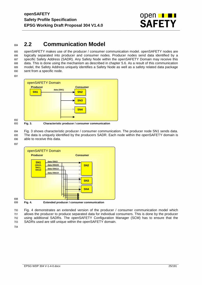
Equation 5. Reduction of residual error probability by proper polynomials 179 549
Equation 6. Reduction of residual error probability by data expectation 180 550
Equation 7. Final residual error probability of openSAFETY 180 551
Equation 8. Maximum message Rate per second to claim SIL 3 180 552
553
554

openSAFETY
Safety Profile Specification
EPSG Working Draft Proposal 304 V1.4.0
EPSG WDP 304 V-1-4-0.docx 18/191
Definitions and Abbreviations 555
For Definitions and Abbreviations of POWERLINK Terms see the POWERLINK Specification. 556
557
Definitions 558
559
Device Vendor Information (DVI) Information for identifying a Safety Node
openSAFETY Layer The openSAFETY Layer defines services to fulfill the requirements of IEC 61508 / SIL 3 for reliability and safety.
openSAFETY Domain (SD) Address space for up to 1023 Safety Nodes
openSAFETY Address (SADR) Address of a Safety Node within an openSAFETY Domain
openSAFETY Domain Number (SDN)
Identification of an openSAFETY Domain
openSAFETY Network Management (SNMT)
Services for openSAFETY Layer Management
openSAFETY Object Dictionary (SOD)
Repository of all data objects accessible over openSAFETY Communication
openSAFETY Process Data Object (SPDO)
Object for process data exchange between openSAFETY Nodes
openSAFETY Service Data Object (SSDO)
Object for service data exchange between openSAFETY Nodes
Safety Node (SN) Node with any safety related function
Safety Configuration Manager (SCM)
Service which is responsible to manage safety related services such as configuration, parameterization and others. Each network with safety related features needs at least one SCM.
openSAFETY Domain Gateway (SDG)
Gateway to share data between different openSAFETY Domains
Unique Device Identification (UDID)
World wide unique identification of a device
560
Abbreviations 561
562
1oo1 One out of One (single channel) Architecture
1oo2 One out of Two Architecture
ACM Automatic Configuration Mode
ADR Address information (source or destination)
BGIA Berufsgenossenschaftliches Institut für Arbeitsschutz
CAN Controller Area Network
CN POWERLINK Control Node
CRC Cyclic Redundancy Check
CT Consecutive Time field (time stamp within a safety frame)
DBx Data Byte
DVI Device Vendor Information
DSADR Destination SADR
openSAFETY
Safety Profile Specification
EPSG Working Draft Proposal 304 V1.4.0
EPSG WDP 304 V-1-4-0.docx 19/191
POWERLINK Ethernet POWERLINK
ID Frame Identification
IP Internet Protocol
LE Length field (specifies number of payload data bytes within a safety frame)
LSB Least Significant Byte
MCM Manual Configuration Mode
MN POWERLINK Managing Node
MSB Most Significant Byte
RxSPDO openSAFETY Receive Process data objects
SADR openSAFETY Address
SCM openSAFETY Configuration Manager
SCT Safety Control Time
SD openSAFETY Domain
SDG openSAFETY Domain Gateway
SDN openSAFETY Domain Number
SIL Safety Integrity Level
SN openSAFETY Node
SNMT openSAFETY Network Management
SOD openSAFETY Object Dictionary
SPDO openSAFETY Process Data Object
SPST Safe parameterization tool
SSDO openSAFETY Service Data Object
SSADR Source SADR
TADR Additional SADR for timing information
TCP Transport Control Protocol
TR Time Request Distinctive Number
TReq Time Synchronization Request
TRes Time Synchronization Response
TÜV Technischer Überwachungsverein
TxSPDO openSAFETY Transmit Process data objects
UDID Unique Device Identification
UDP User Datagram Protocol
563

openSAFETY
Safety Profile Specification
EPSG Working Draft Proposal 304 V1.4.0
EPSG WDP 304 V-1-4-0.docx 20/191
References 564
[1]: Grundsatz für die Prüfung und Zulassung von „Bussystemen für die Übertragung 565
sicherheitsrelevanter Nachrichten“ Fachausschuss Elektrotechnik, Gustav-Heinemann-Ufer 566
130, 50698 Köln, Version May 2002. 567
[2]: IEC 61508, Functional safety of electric/electronic/programmable electronic safety-related 568
systems, IEC part 1-7 569
[3]: Philip Koopman, Tridib Chakravarty: Cyclic Redundancy Code (CRC) Polynomial Selection for 570
Embedded Networks 571
[4]: EN 50159-1:2001 Railway applications - Communication, signalling and processing systems - 572
Part 1: Safety related communication in closed transmission systems 573
[5]: EN 50159-2:2001 Railway applications - Communication, signalling and processing systems - 574
Part 2: Safety related communication in open transmission systems 575
[6]: Philip Koopman, 32-Bit Cyclic Redundancy Codes for Internet Applications 576
[7]: FH Campus Wien, University of Applied Sciences / VISSE, openSAFETY: Studie zur CRC-577
Qualität und Restfehlerrate, Version 0.5, Juni 2011… 578

openSAFETY
Safety Profile Specification
EPSG Working Draft Proposal 304 V1.4.0
EPSG WDP 304 V-1-4-0.docx 21/191
1 Introduction 579
Safety-relevant electronic systems are used to an ever increasing extent in practically every area of 580
automation. New regulative measures from the legislator, which are intended to ensure the safety and 581
integrity of humans and goods, are leading to a growing need for systems in complex control and 582
automation systems in all sectors of industry. One of the most important standards to meet an 583
appropriate level of safety is the international standard EN IEC 61508. Actually, safety-related systems 584
in automation continue for the most part to be discreetly wired and electromechanically controlled. 585
With the spread of fieldbus systems and programmable control systems, the desire to use them in 586
safety equipment is also growing. Standardized components and networks are expected to deliver 587
considerable cost savings, simplified maintenance and increased flexibility. 588
589
More recent attempts at safety fieldbuses are often characterized by proprietary standards and limited 590
cycle times in the millisecond range. As a result of the rapidly advancing development of Ethernet 591
solutions for automation, these traditional safety protocols will be of little significance in the future. An 592
analysis of existing safety protocols has shown that they are not suitable as a base for open and real-593
time-capable Ethernet communication. It is for that reason that the openSAFETY Working Group was 594
established on July 27, 2004, within the EPSG. Its objective is to define a forward-looking open safety 595
protocol for Ethernet-based communication in the microsecond range. 596
1.1 Referenced Standards 597
The requirements of safety related bus systems are summarized in the BGIA certification standards 598
for bus systems with safety related data transfer on a standard network. This method relies on 599
providing measures for possible transmission errors as defined in EN 50159-1 [4], EN 50159-2 [5]. 600
Basically the referenced standards for openSAFETY devices are the IEC 61508 [2] or comparable 601
standards. 602
1.2 openSAFETY key features 603
openSAFETY is defined as a bus-independent, autonomous frame, which can in principle also be 604
inserted into standard protocols other than POWERLINK. openSAFETY has been designed so that 605
standard data and safety data transfer is possible within the same network. 606
607
Safety level SIL 3 according to IEC 61508 [2] is achieved for the first time with cycle times down to the 608
microseconds range. 609
610
Thanks to the very flexible construction of the frames, openSAFETY can be adapted extremely well to 611
various applications such as machines, installations or transport systems. The frame length is 612
determined by the reference data needed by the application. 613
614
openSAFETY stands out with its uniform telegram format for different data purposes (payload data, 615
configuration, time synchronization). Each openSAFETY node automatically recognizes the data 616
purpose of the telegram. Thus, the telegram length and type does not need to be configured 617
separately. As a consequence implementation and handling become much easier. The flexible 618
standard format permits a bandwidth of between 0 and 254 bytes of payload data. A new technology 619
enables the CRC type to be automatically configured in relation to the length byte. 620
621
Its long protocol proves to be a particular advantage – it is also based on the standard format and 622
permits full use of the Ethernet telegram. Even the most varied requirements present no problem, 623

openSAFETY
Safety Profile Specification
EPSG Working Draft Proposal 304 V1.4.0
EPSG WDP 304 V-1-4-0.docx 22/191
thanks to the flexible and uniform openSAFETY telegram format. openSAFETY already meets the 624
future requirements of distributed automation structures with integrated safety technology. 625
626
openSAFETY guarantees Real Time Ethernet Communication with the following features: 627
Data transfer time down to 100 µs 628
Fulfills the error probability rate up to SIL3 according to IEC 61508 629
Standard and safety related devices can be used in the same network 630
Preferred use with CAN as sub-bus 631
Supports complex architectures for network-structures 632
Routable via standard (non safety related) gateways 633
Independence of transport media 634
Maximum of 1023 safety related devices within 1 safety domain 635
Supports 1023 safety domains 636
Compatible to Ethernet TCP/IP with POWERLINK as the underlying communication layer 637
1.3 Integration 638
openSAFETY is fundamentally independent from the underlying communication layer. The 639
openSAFETY frame is encapsulated with its safety measures within the standard communication. For 640
this communication, any existing Ethernet communication protocol or field bus may be used. The 641
security of the openSAFETY communication against unauthorized access (hacker, viruses, attacks …) 642
depends on the protection of the underlying communication layer. 643
644
645
Fig. 1. Integration of openSAFETY into the IT infrastructure of end customer 646
The openSAFETY Domain (SD) and the openSAFETY Domain Gateway (SDG) allow the safety 647
related communication through different network structures. Safety related communication of the 648
Factory Floor Network and Company Network
Network A (Powerlink)
Network (Ethernet TCP/IP)
Network C (CAN)
openSAFETY Domain 1
openSAFETY Domain 2
openSAFETY Domain n
MN
CAN-Node
CN
CN
SCM
SN2
SN1
SN1
SDgateway
SN3
SN3
SN2
SN5
SN4
SCM
SN1
SCM
IP Node
Firewall
Powerlink Basic Security

openSAFETY
Safety Profile Specification
EPSG Working Draft Proposal 304 V1.4.0
EPSG WDP 304 V-1-4-0.docx 23/191
safety devices within one openSAFETY Domain is limited to the openSAFETY nodes. One 649
openSAFETY Domain can include openSAFETY nodes in different types of networks. The 650
openSAFETY Domain number must be unique within the manageable network scope. openSAFETY 651
Domain Gateway is a special device which is able to communicate with different openSAFETY 652
domains. 653
1.4 Modular Machines 654
Each machine module can be designed separately with its own internal communication relationships. 655
The assembling of the machine can be done in a flexible way by adding additional direct relationships 656
between machine modules. Also openSAFETY supports inter-domain safety communication between 657
different safety networks (machine modules) with a safety gateway. This gateway can be implemented 658
within an SCM. Additionally openSAFETY supports the efficient assembling of machine modules with 659
less configuration effort. Of course organizational safety measures have to be considered when 660
rebuilding a machine. 661

openSAFETY
Safety Profile Specification
EPSG Working Draft Proposal 304 V1.4.0
EPSG WDP 304 V-1-4-0.docx 24/191
2 Modeling 662
2.1 Reference Model 663
openSAFETY basically consists of an encapsulated data representation and transport definition 664
(openSAFETY Data Services) and upper level services similar to POWERLINK. 665
The openSAFETY Nework Management (SNMT) ensures the required services for the openSAFETY 666
Configuration Manager (SCM) to configure and verify the safety related nodes within the network. The 667
openSAFETY service data objects (SSDO) provide all needed services to access the openSAFETY 668
Object Dictionary (SOD) and to support the SCM. The openSAFETY Process data objects (SPDO) are 669
responsible for safety related process data exchange between certain entries within the SOD of 670
communicating nodes. The time synchronization services, which are part of SPDO, verify the network 671
performance between the communicating nodes. 672
Finally, the openSAFETY Object Dictionary (SOD) describes the format and access of the device 673
specific data, and the openSAFETY Configuration Manager (SCM) includes start-up, parameterization 674
and all further measures to ensure safe operation over the entire life cycle of the application. These 675
two components interface the openSAFETY layer to the safety related application. 676
Chapter 5 of this specification describes the components of the openSAFETY layer in detail. 677
678
Fig. 2. Reference Model 679
The usage of an underlying communication layer is mandatory. Since there are no safety related 680
requirements to this layer (see chapter 4), any existing Ethernet based or non Ethernet based field bus 681
or transport protocol is applicable. 682
683
openSAFETY Layer
Communication Layer
Ethernet
UDP
IP
openSAFETY Data Services
openSAFETY Process Data Object (SPDO)
TCP
…
EPL
…
CAN
…
openSAFETY Service Data Object
(SSDO)
openSAFETY Object Dictionary (SOD)
openSAFETY Network
Management (SNMT)
Safety related Application
Time
Synchronization
openSAFETY Configuration Manager
(SCM)
openSAFETY
Safety Profile Specification
EPSG Working Draft Proposal 304 V1.4.0
EPSG WDP 304 V-1-4-0.docx 25/191
2.2 Communication Model 684
openSAFETY makes use of the producer / consumer communication model. openSAFETY nodes are 685
logically separated into producer and consumer nodes. Producer nodes send data identified by a 686
specific Safety Address (SADR). Any Safety Node within the openSAFETY Domain may receive this 687
data. This is done using the mechanism as described in chapter 5.6. As a result of this communication 688
model, the Safety Address uniquely identifies a Safety Node as well as a safety related data package 689
sent from a specific node. 690
691
692
Fig. 3. Characteristic producer / consumer communication 693
Fig. 3 shows characteristic producer / consumer communication. The producer node SN1 sends data. 694
The data is uniquely identified by the producers SADR. Each node within the openSAFETY domain is 695
able to receive this data. 696
697
698
Fig. 4. Extended producer / consumer communication 699
Fig. 4 demonstrates an extended version of the producer / consumer communication model which 700
allows the producer to produce separated data for individual consumers. This is done by the producer 701
using additional SADRs. The openSAFETY Configuration Manager (SCM) has to ensure that the 702
SADRs used are still unique within the openSAFETY domain. 703
704
openSAFETY Domain
Producer Consumer
openSAFETY Domain
Producer Consumer
SN1 (SN10, SN11, SN12)
SN2
SN1
SN2
SN3
SN4
data (SN1)
data (SN1)
SN3
SN4
data (SN10)
data (SN11)
data (SN12)

openSAFETY
Safety Profile Specification
EPSG Working Draft Proposal 304 V1.4.0
EPSG WDP 304 V-1-4-0.docx 26/191
705
Fig. 5. Server Client communication 706
Fig. 5 shows the server client communication mainly used for configuration services and network 707
management. The SCM (or a dedicated configuration tool, see chapter 6) acts as the client. SNs are 708
limited to act as a server. 709
710
Using the Client/Server communication model, the client (SCM or Tool) sends a request to the server 711
(SN) which is addressed within the ADDR Field (see 5.1.1.3) using the server address and also 712
contains the client address within the TADR Field (see 5.1.1.9). The server replies with a response 713
which is addressed within the ADDR Field (see 5.1.1.3) using the server address and also contains 714
the client address within the TADR Field (see 5.1.1.9). 715
2.3 openSAFETY Topology 716
openSAFETY uses the following building blocks to set up a safety related topology: 717
openSAFETY Node (SN) any openSAFETY compliant device 718
openSAFETY Domain (SD) address space of up to 1023 SNs 719
openSAFETY Configuration Manager(SCM) central service for managing openSAFETY 720
openSAFETY Domain Gateway (SDG) openSAFETY device to exchange data 721
between different SDs 722
723
724
Fig. 6. openSAFETY Topology Schema 725
726
SD1
SN1
SCM
SN2
SN3
SNn
SD2
SN10
SCM
SN11
SNn
SD3
SN10
SCM
SN21
SNn
SDG
SN12
SN22
openSAFETY Domain
Client Server
SN1 SCM
SN2
Request (SN2/SN1)
Response (SN2/SN1)
SN3
Request (SN3/SN1)
Response (SN3/SN1)
SN4
Request (SN4/SN1)
openSAFETY
Safety Profile Specification
EPSG Working Draft Proposal 304 V1.4.0
EPSG WDP 304 V-1-4-0.docx 27/191
Fig. 6 demonstrates possible safety related topologies using openSAFETY. SD1 gives an example of 727
a simple openSAFETY Domain. Safety related communication of the safety devices within SD1 is 728
limited to the openSAFETY nodes within SD1. 729
730
SD2 in combination with SD3 shows the possibility to set up an openSAFETY inter-domain 731
communication. This is done using a special openSAFETY device (SDG) which is able to 732
communicate with different openSAFETY domains. Inter-domain Communication is handled by the 733
device internally. SDG capability may be independent of the SCM capability of a device. The SDG has 734
one SADR in SD2 and one SADR in SD3. 735
2.3.1 openSAFETY Node (SN) 736
An openSAFETY Node is a node within any network which conforms to this specification. An SN is 737
identified by 738
739
A logical address which is unique within the SD. The address is called openSAFETY Address 740
(SADR). The number range for the SADR is 1 to 1023 (0 is reserved). The SADR will be defined 741
by the programmer or by the programming tool. Duplicate SADRs within an SD will be detected 742
by the SCM during network verification at start-up of the SCM or at start-up of any node within 743
the openSAFETY domain. 744
745
A physical address which is globally unique. The address is called openSAFETY Unique Device 746
Identification (UDID). Duplicate UDIDs within an SD will be detected by the SCM. 747
748
For operation, an SN may need further data like safety related parameters or application data. It 749
depends on the capability of the device, where this data is stored: 750
751
At least the device specific firmware, the UDID and the openSAFETY Device Vendor Information 752
(DVI) (see Chapter 5.6.4.7) must be stored permanently on the device. There is no support within 753
openSAFETY to change this data via the network. 754
755
Simple SNs without permanent memory receive SDN, SADR and all further parameters from the 756
SCM after power up. This requires permanent storage of this SN specific data on the SCM. 757
758
Complex SNs with permanent memory or switches to adjust the SDN and SADR will hold their 759
data permanently on the device. The SCM only has to store the data which is not permanently 760
stored on the SN, for the other data the SCM has only to verify them. 761
2.3.2 openSAFETY Domain (SD) 762
An openSAFETY Domain forms an address space of up to 1023 SADR for SNs belonging together. 763
SNs within the same SD are able to communicate directly. SNs between different SDs are only able to 764
do this with the help of an openSAFETY Domain Gateway. 765
766
An SD is identified by the openSAFETY Domain Number (SDN) having a number range of 1 to 1023 767
(0 is reserved). The SDN is defined manually. When planning the application layout, unique SDNs 768
must be ensured. 769

openSAFETY
Safety Profile Specification
EPSG Working Draft Proposal 304 V1.4.0
EPSG WDP 304 V-1-4-0.docx 28/191
2.3.2.1 openSAFETY Domain Protection 770
The danger of an external attack of openSAFETY within the process data (SPDO) is negligible. But 771
there is a potential risk for the configuration services. When using the Internet in connection with 772
openSAFETY, the security of the system must be observed. Proper state of the art security measures 773
must be applied.. 774
775
Fig. 7. openSAFETY Domain Protection 776
2.3.2.2 openSAFETY Domain Separation 777
Interaction between openSAFETY Domains as well as the danger of confusion during configuration 778
and parameterization is excluded by using unique openSAFETY Domain Numbers. 779
780
If the size of the company intranet and the organization of the network management do not allow 781
overlooking unique openSAFETY Domain Numbers, it’s recommended to split it to several 782
manageable network scopes and separate them by established methods like firewalls. 783
To avoid safety critical situation, the SPDO and SSDO services are additionally coded to be unique 784
within a certain openSAFETY Domain (see 5.1.1.11). 785
786
Fig. 8. openSAFETY Domain Separation 787
788
Network 2
Network 1
Network 3
openSAFETY Domain #1
openSAFETY Domain #2
openSAFETY Domain #1
Internet
Company Intranet
Machine or Process Level Network
Manageable Network Scope A Scope B
SN4
Firewall
Network 2
Network 1
Network 3
openSAFETY Domain #1
openSAFETY Domain #2
openSAFETY Domain #3
Internet
Company Intranet
Machine or Process Level Network
Programming & Parameterisation
Programming & Parameterisation
State of the art security
measures
openSAFETY
Safety Profile Specification
EPSG Working Draft Proposal 304 V1.4.0
EPSG WDP 304 V-1-4-0.docx 29/191
2.3.3 openSAFETY Domain Gateway (SDG) 789
This is a special openSAFETY device which is able to communicate with different openSAFETY 790
Domains. Inter-domain communication is handled by the SDG internally. Within an SD, the SDG looks 791
like a standard SN. 792
2.3.4 openSAFETY Configuration Manager (SCM) 793
The openSAFETY Configuration Manager (SCM) is centrally responsible for managing openSAFETY. 794
Within an openSAFETY Domain, only one SN running the SCM service is permitted. 795
796
The SCM is responsible for permanent storage of SN specific parameters which are not stored on the 797
SN (see 2.3.1), for unique assignment and verification of the SADR of the SNs within the SD, for 798
verification of the uniqueness of the UDID within the SD, for verification of the expected parameters 799
and DVI of the SNs, and for sending a periodic life guard signal to all SNs within the SD. This periodic 800
life guard signal from the SCM is required within the SN to detect certain failure situations where no 801
SCM is responsible for the SN. 802
openSAFETY
Safety Profile Specification
EPSG Working Draft Proposal 304 V1.4.0
EPSG WDP 304 V-1-4-0.docx 30/191
3 openSAFETY Life Cycle Model 803
openSAFETY supports the application during several phases of its life cycle concerning IEC 61508 804
[2]. The safety-related communication is only one part of the complete safety concept of the 805
machinery. Of course, the other safety related parts of the machinery have to be considered as well. 806
This chapter focuses only on safety-related communication with openSAFETY. 807
3.1 Concept, Planning and Implementation 808
3.1.1 Application Layout 809
When designing the application layout, the characteristics of openSAFETY must be taken in account. 810
The following possibilities and restrictions must be observed: 811
openSAFETY Domain, assigning SDNs 812
Separation and Protection of openSAFETY Domains 813
openSAFETY Addresses 814
openSAFETY Configuration Manager 815
Inter-Domain Communication 816
3.1.2 Programming and Parameterization 817
Programming and Parameterization must be carried out using safety related tools. Application files 818
and parameters will be stored in the SCM device only or directly in the corresponding device 819
depending on the device capabilities. 820
821
Programming and parameterizing the safety related application: 822
Accessing SNs within an SD is referenced by the SADR only. This allows installing several 823
identical applications with different SDNs without changing the application. 824
Communication to other SDs is only possible via an SDG 825
Locate SCM service 826
List DVI of the devices 827
Implement safety related application 828
Specify safety related parameters (see chapter 5.6) 829
830
The SCM is the central managing node to configure and verify the safety related devices. 831
openSAFETY supports two different strategies for configuration . This is necessary to satisfy all 832
requirements coming from the wide range of application openSAFETY is ready for. 833
834

openSAFETY
Safety Profile Specification
EPSG Working Draft Proposal 304 V1.4.0
EPSG WDP 304 V-1-4-0.docx 31/191
3.1.2.1 Automatic Configuration Mode (ACM) 835
Using the automatic configuration mode (ACM), the system automatically gathers the UDID from the 836
connected SNs. The ACM may be used only if the following items are fulfilled: 837
all connectable safety related devices can be connected at one time within the basic 838
configuration of the network 839
one device (single UDID) for each SN with a specific SADR 840
if a safety related device is replaced, the SCM verifies that the new device is of the same type 841
as the replaced one. If this is fulfilled, the new UDID will be gathered and the operator has to 842
confirm the replacement. 843
3.1.2.2 Manual Configuration Mode (MCM) 844
Manual configuration mode is applicable for all kinds of applications, however this mode requires 845
manual configuration of the safety related devices. So, this mode is mainly intended for applications 846
with the following features: 847
all connectable safety related devices can not be connected at one time 848
Example: robotic arm with several safety related tools 849
multiple devices (multiple UDID) for an SN with a specific SADR 850
Example: modular machine application with several machine lines within the plant. Machine 851
module A (equals to the SADR) may be used for all machine lines. For bottleneck reasons, 852
there is more than one piece of equipment (let’s say more than one UDID) for module A 853
(=SADR), and these pieces of equipment (UDID) are all applicable on each machine line. 854
Module replace must be handled automatically without manual intervention 855
3.2 Commissioning 856
Commissioning can be separated into three main steps. 857
Installing the application 858
Setting up the configuration depending on the configuration mode (see chapter 3.1.2) 859
Verification of the safety functionality 860
3.2.1 Installation 861
First install applications and parameters on the openSAFETY devices using: 862
an openSAFETY compliant programming tool which uses the specified openSAFETY services 863
(see Chapter 6). 864
proprietary safety related transfer protocol to exchange data from the programming system to 865
a safety related device via network or direct communication connection (e.g. serial line) 866
867
For this step the capability of the device decides what data and where the data must be 868
downloaded: 869
if the device itself holds the data, the data must be downloaded to the device. 870
if the device is not able to hold the data, the data is stored on the SCM. The SCM ensures the 871
proper update of all devices during power up using the openSAFETY configuration services. 872
873
After them Update SDN if needed (see chapter 2.3) 874
openSAFETY
Safety Profile Specification
EPSG Working Draft Proposal 304 V1.4.0
EPSG WDP 304 V-1-4-0.docx 32/191
3.2.2 Configuration Setup 875
3.2.2.1 Configuration Setup using ACM 876
Connect all safety related devices to the network 877
Power up of all safety related devices 878
Make sure communication layer works for all SNs 879
SCM starts gathering UDID (without operator interference) 880
The Commissioner has to acknowledge each device 881
3.2.2.2 Configuration Setup using MCM 882
The commissioner has to enter the list of possible SADRs with the corresponding UDIDs 883
manually, therefore a safety related configuration tool must be used 884
The SCM will accept all configured SADR / UDID combinations 885
The SCM will not accept mismatches and will not repair mismatches as done in the ACM. This 886
means, all mismatches must be corrected by the commissioner by entering the corrected 887
value using the safety related configuration tool 888
3.2.3 Verification 889
The commissioner has to verify the safety functionality against the safety specification for the 890
application. In the case of device replacements or changes in the routing within the 891
communication layer, the commissioner has to continue with step 3.2.2. 892
893
If verification is carried out during commissioning, all combinations of exchangeable modules 894
must be verified. This is especially important in the case of complex modular machines (in 895
combination with MCM). 896
897
If verification is carried out due to maintenance, only the safety related functionality affected by 898
the maintenance task must be verified. 899
900
When verification is finished, an installation specific backup of the current configuration should 901
be made. 902
903
In case of an SCM replacement, a download of application files, parameters, and the 904
configuration has to be done otherwise the commissioning steps (installation, configuration 905
and verification) must be repeated. 906
907
openSAFETY
Safety Profile Specification
EPSG Working Draft Proposal 304 V1.4.0
EPSG WDP 304 V-1-4-0.docx 33/191
3.3 Operation Terms 908
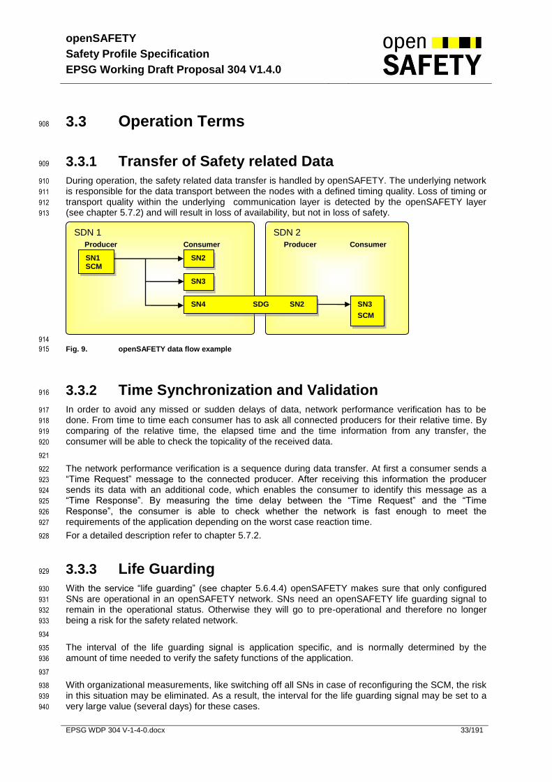
3.3.1 Transfer of Safety related Data 909
During operation, the safety related data transfer is handled by openSAFETY. The underlying network 910
is responsible for the data transport between the nodes with a defined timing quality. Loss of timing or 911
transport quality within the underlying communication layer is detected by the openSAFETY layer 912
(see chapter 5.7.2) and will result in loss of availability, but not in loss of safety. 913
914
Fig. 9. openSAFETY data flow example 915
3.3.2 Time Synchronization and Validation 916
In order to avoid any missed or sudden delays of data, network performance verification has to be 917
done. From time to time each consumer has to ask all connected producers for their relative time. By 918
comparing of the relative time, the elapsed time and the time information from any transfer, the 919
consumer will be able to check the topicality of the received data. 920
921
The network performance verification is a sequence during data transfer. At first a consumer sends a 922
“Time Request” message to the connected producer. After receiving this information the producer 923
sends its data with an additional code, which enables the consumer to identify this message as a 924
“Time Response”. By measuring the time delay between the “Time Request” and the “Time 925
Response”, the consumer is able to check whether the network is fast enough to meet the 926
requirements of the application depending on the worst case reaction time. 927
For a detailed description refer to chapter 5.7.2. 928
3.3.3 Life Guarding 929
With the service “life guarding” (see chapter 5.6.4.4) openSAFETY makes sure that only configured 930
SNs are operational in an openSAFETY network. SNs need an openSAFETY life guarding signal to 931
remain in the operational status. Otherwise they will go to pre-operational and therefore no longer 932
being a risk for the safety related network. 933
934
The interval of the life guarding signal is application specific, and is normally determined by the 935
amount of time needed to verify the safety functions of the application. 936
937
With organizational measurements, like switching off all SNs in case of reconfiguring the SCM, the risk 938
in this situation may be eliminated. As a result, the interval for the life guarding signal may be set to a 939
very large value (several days) for these cases. 940
SDN 2
Producer Consumer
SDN 1
Producer Consumer
SN1 SCM
SN2
SN3
SN3
SCM
SN4 SDG SN2

openSAFETY
Safety Profile Specification
EPSG Working Draft Proposal 304 V1.4.0
EPSG WDP 304 V-1-4-0.docx 34/191
3.3.4 Startup after Power up or Reset 941
After Power Up the SCM (see chapter 5.7.9) handles the network verification. If there was no change 942
within the network, no special tasks are required. 943
3.3.5 Recover from Network Failure 944
Following a network breakdown, all affected SNs will enter the pre-operational state. Since 945
corresponding consumer SNs will get no further data, these nodes will enter the fail state. 946
After recovery of the network, all affected SNs send an SNMT_SN_in_PRE_OP service to the SCM. 947
The SCM then will start with the initialization of the SNs. 948
3.4 Maintenance Terms 949
3.4.1 Diagnostic Information 950
Diagnostic Information according to chapter 5.6.4 will be stored in the object 1001h, 1002h, 1003h by 951
the SN. This information can be read by the non safety related application. 952
3.4.2 Replace safety related devices 953
3.4.2.1 SN Replacement 954
After replacing the affected SNs, the maintenance technician has to decide: 955
If only one SN is replaced, is the SCM able to handle the replacement automatically? Only a 956
simple confirmation by the maintenance technician is requested. 957
If more than one SN is replaced, the configuration (see chapter 3.2.2) must be repeated and 958
verification of the safety functionality of the replaced SNs must be done (see chapter 3.2.3). 959
3.4.2.2 Replacement of SN running the SCM 960
If the configuration and the application with the corresponding parameters are available after the 961
replacement, the SCM replacement has no influence on the safety functions. If any data is lost, the 962
steps according to 3.2 must be repeated. In accordance with 3.2.3, a complete verification is 963
necessary (as it is required during commissioning). 964
3.4.3 Modification 965
After modification, the steps according to 3.2 must be repeated. In accordance with 3.2.3, a complete 966
verification is necessary (as it is required during commissioning). 967
968
openSAFETY
Safety Profile Specification
EPSG Working Draft Proposal 304 V1.4.0
EPSG WDP 304 V-1-4-0.docx 35/191
3.4.4 Machine part changing 969
All changeable machine parts have to be verified against the safety specification for the application at 970
least one time according to the procedure listed in 3.2.3. After verification, the SCM knows the 971
configuration for all changeable machine parts, this means that after changing machine parts, no 972
further steps are required. 973
974
Open input situations due to missing producers after machine part changes must be handled by the 975
application. 976
3.4.5 Firmware update of safety related nodes 977
A firmware update for a safety related node is a vendor specific task. There is no service within 978
openSAFETY to support this task. 979
3.4.6 Machine check due to service interval 980
openSAFETY requires no special check. 981

openSAFETY
Safety Profile Specification
EPSG Working Draft Proposal 304 V1.4.0
EPSG WDP 304 V-1-4-0.docx 36/191
4 Non safe Communication Layer 982
4.1 Requirements to Data Transport 983
The communication layer is responsible for transporting the data between the SNs. The coexistence of 984
standard nodes and safety related nodes is allowed. To avoid any possibilities of masquerading as 985
openSAFETY frames, non openSAFETY related nodes may not contain code which is able to 986
generate openSAFETY frames according to chapter 5 of this specification. 987
988
The communication layer is permitted to carry out read only access of data within the openSAFETY 989
frame. This must be done by accessing the data within the openSAFETY frame without using the 990
openSAFETY frame specific data corruption methods, such as CRC and data repetition of sub frame 1 991
in sub frame 2. 992
4.1.1 Transport of SPDO 993
The communication layer has to transport the SPDO data between the SNs. When using the Internet 994
in connection with openSAFETY, the established methods for encryption (Virtual Private Network, 995
VPN) have to be used. Within local area networks, organizational actions like firewalls have to be 996
implemented. 997
4.1.2 Transport of SSDO 998
The communication layer has to transport the SSDO data between the SNs. When using the Internet 999
in connection with openSAFETY, the established methods for encryption (Virtual Private Network, 1000
VPN) have to be used. Within local area networks, organizational actions like firewalls have to be 1001
implemented. 1002
4.2 Representation of Diagnostic Data 1003
The communication layer has to support services to provide openSAFETY specific diagnostic data 1004
according to chapter 5 of this specification. 1005
4.3 Safety Domain Protection and Separation 1006
In accordance with chapter 2 of this specification, the communication layer has to support proper 1007
security features to protect the openSAFETY domain against attacks from outside and to avoid 1008
interferences between separated openSAFETY domains. 1009

openSAFETY
Safety Profile Specification
EPSG Working Draft Proposal 304 V1.4.0
EPSG WDP 304 V-1-4-0.docx 37/191
5 openSAFETY Layer 1010
5.1 openSAFETY Data Services 1011
5.1.1 Structure of openSAFETY Frame 1012
5.1.1.1 Basic openSAFETY Frame 1013
This chapter shows the structure of the Basic openSAFETY frame. The frame consists of two sub 1014
frames and is able to transport data up to 254 bytes of payload data. The error probability and the 1015
hamming distance in relation to the frame length can be viewed in Chapter 8. The frame uses two 1016
kinds of CRCs depending on the length of the payload data: 1017
1018
1019
Fig. 10. Data format of a basic openSAFETY frame up to 8 byte of payload data 1020
1021
Fig. 11. Data format of a basic openSAFETY frame from 9 byte of payload data 1022
1023
ID ADR LE CT(L) DB0 CRC16 DBn ID ADR CT(M) TR TADR DB0 CRC16
sub frame one / sub frame two
DBn
SDN
UDID of SCM
sub frame one / sub frame two
ID
ADR
LE CT(L) DB0 CRC8 DBn ID ADR CT(M) DB0 CRC8 DBn TR TADR
SDN
UDID of SCM

openSAFETY
Safety Profile Specification
EPSG Working Draft Proposal 304 V1.4.0
EPSG WDP 304 V-1-4-0.docx 38/191
1024
Bit Offset
Octet Offset1 7 6 5 4 3 2 1 0
0 ADR (Bit 0-7)
1 ID ADR (8,9)
2 LE
3 CT (Bit 0-7)
4 … (n-1)+4 DB 0 to DB n
n+4 … n+4+o CRC-8 / CRC-16
n+5+o ADR (Bit 0-7) XOR SDN (Bit 0-7)
n+6+o ID ADR (8,9) XOR SDN (8,9)
n+7+o CT (Bit 8-15)
n+8+o TADR (Bit 0-7)
n+9+o TR TADR (8,9)
n+10+o … 2n+9+o DB 0 to DB n
2n+10+o … 2n+10+2o CRC-8 / CRC-16
Tab. 1 Basic openSAFETY frame 1025
Table Tab. 1 shows the structure of the Basic openSAFETY frame. The frame may be devided in two 1026
sub frames, called sub frame one and sub frame two. The grey colored lines within table Tab. 1 1027
indicate sub frame two. Sub frame two of SPDO and SSDO Frames (not SNMT Frames) are 1028
additionally coded with the UDID of the SCM using a logical XOR operation (see chapter 5.1.1.11). 1029
1030
The formula for the end position for the safety payload in the second frame is calculated baring the 1031
end position of the first frame in mind: ( ) . By reducing the formula the result is : 1032
. 1033
1034
1 Octet Offset refers to the start of the openSAFETY telegram.
n … number of payload data in bytes 0 ≤ n ≤ 254 o … CRC correction offset 0 ≤ n ≤ 8 o = 0 (CRC 8) 9 ≤ n ≤ 254 o = 1 (CRC16)

openSAFETY
Safety Profile Specification
EPSG Working Draft Proposal 304 V1.4.0
EPSG WDP 304 V-1-4-0.docx 39/191
5.1.1.2 Slim SSDO openSAFETY Frame 1035
This chapter shows the structure of the Slim SSDO openSAFETY frame. The frame consists of two 1036
sub frames and is able to transport data up to 254 bytes of payload data. The error probability and the 1037
hamming distance in relation to the frame length can be viewed in Chapter 8. The frame uses two 1038
kinds of CRCs depending on the length of the payload data: 1039
1040
Fig. 12. Data format of a slim SSDO frame up to 8 byte of payload data 1041
1042
Fig. 13. Data format of a slim SSDO frame from 9 byte of payload data 1043
1044
Bit Offset
Octet Offset2 7 6 5 4 3 2 1 0
0 ADR (Bit 0-7)
1 ID ADR (8,9)
2 LE
3 CT (Bit 0-7)
4 … (n-1)+4 DB 0 to DB n
n+4 … n+4+o CRC-8 / CRC-16
n+5+o ADR (Bit 0-7) XOR SDN (Bit 0-7)
n+6+o ID ADR (8,9) XOR SDN (8,9)
n+7+o CT (Bit 8-15)
n+8+o TADR (Bit 0-7)
n+9+o TR TADR (8,9)
n+10+o … n+10+2o CRC-8 / CRC-16
Tab. 2 Slim SSDO openSAFETY frame 1045
Table Tab. 2 shows the structure of the Slim SSDO openSAFETY frame. The frame may be devided 1046
in two sub frames, called sub frame one and sub frame two. The grey colored lines within table Tab. 2 1047
indicate the data of sub frame two. The data of sub frame two is additionally coded with the UDID of 1048
the SCM using a logical XOR operation (see chapter 5.1.1.11). 1049
2 Octet Offset refers to the start of the openSAFETY telegram.
n … number of payload data in bytes 0 ≤ n ≤ 254 o … CRC correction offset 0 ≤ n ≤ 8 o = 0 (CRC 8) 9 ≤ n ≤ 254 o = 1 (CRC16)
sub frame one / sub frame two
ID ADR LE CT(L) DB0 CRC8 DBn ID ADR CT(M) CRC8 TR TADR
SDN
UDID of SCM
ID ADR LE CT(L) DB0 CRC16 DBn ID ADR CT(M) TR TADR CRC16
sub frame one / sub frame two
SDN
UDID of SCM
openSAFETY
Safety Profile Specification
EPSG Working Draft Proposal 304 V1.4.0
EPSG WDP 304 V-1-4-0.docx 40/191
5.1.1.3 Address Field (ADR) 1050
The address field (ADR) defines the SADR of the SN. The field is a 10 bit value. By using the address, 1051
1023 devices can be addressed (ADR = 0 is not allowed). 1052
1053
The address Field within the second sub frame is also used to carry the openSAFETY domain number 1054
(SDN) information using a logical XOR operation (see chapter 5.1.1). 1055
1056
The ADR field may contain the SADR of the SN from which the frame is sent (source address) or for 1057
which the frame is designated (destination address). The source address is the SADR of the SN which 1058
sends the telegram, the destination address is the SADR of the SN which the telegram is sent to. 1059
1060
According the content of the ADR fields of both sub frames, the non safe communication layer is able 1061
to transport the data to the designated destination node without additional analyzing the ID field or 1062
other openSAFETY specific frame attributes. 1063
1064
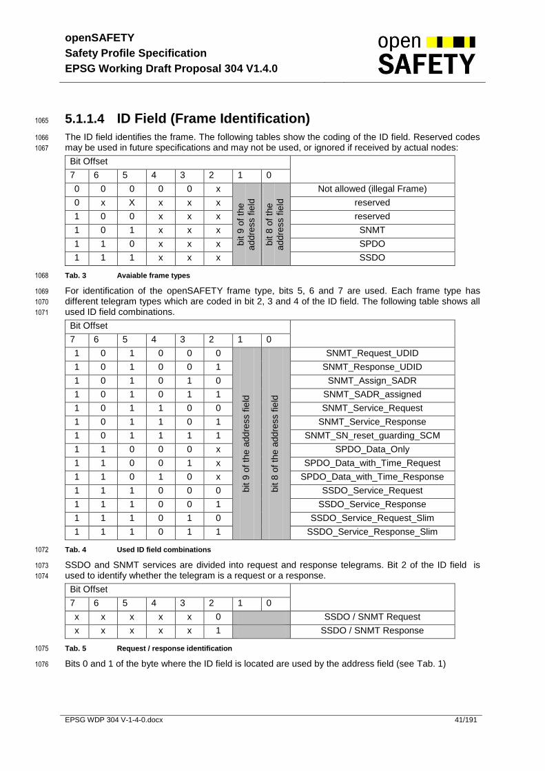
openSAFETY
Safety Profile Specification
EPSG Working Draft Proposal 304 V1.4.0
EPSG WDP 304 V-1-4-0.docx 41/191
5.1.1.4 ID Field (Frame Identification) 1065
The ID field identifies the frame. The following tables show the coding of the ID field. Reserved codes 1066
may be used in future specifications and may not be used, or ignored if received by actual nodes: 1067
Bit Offset
7 6 5 4 3 2 1 0
0 0 0 0 0 x
bit 9
of th
e
addre
ss fie
ld
bit 8
of th
e
addre
ss fie
ld
Not allowed (illegal Frame)
0 x X x x x reserved
1 0 0 x x x reserved
1 0 1 x x x SNMT
1 1 0 x x x SPDO
1 1 1 x x x SSDO
Tab. 3 Avaiable frame types 1068
For identification of the openSAFETY frame type, bits 5, 6 and 7 are used. Each frame type has 1069
different telegram types which are coded in bit 2, 3 and 4 of the ID field. The following table shows all 1070
used ID field combinations. 1071
Bit Offset
7 6 5 4 3 2 1 0
1 0 1 0 0 0
bit 9
of th
e a
ddre
ss f
ield
bit 8
of th
e a
ddre
ss f
ield
SNMT_Request_UDID
1 0 1 0 0 1 SNMT_Response_UDID
1 0 1 0 1 0 SNMT_Assign_SADR
1 0 1 0 1 1 SNMT_SADR_assigned
1 0 1 1 0 0 SNMT_Service_Request
1 0 1 1 0 1 SNMT_Service_Response
1 0 1 1 1 1 SNMT_SN_reset_guarding_SCM
1 1 0 0 0 x SPDO_Data_Only
1 1 0 0 1 x SPDO_Data_with_Time_Request
1 1 0 1 0 x SPDO_Data_with_Time_Response
1 1 1 0 0 0 SSDO_Service_Request
1 1 1 0 0 1 SSDO_Service_Response
1 1 1 0 1 0 SSDO_Service_Request_Slim
1 1 1 0 1 1 SSDO_Service_Response_Slim
Tab. 4 Used ID field combinations 1072
SSDO and SNMT services are divided into request and response telegrams. Bit 2 of the ID field is 1073
used to identify whether the telegram is a request or a response. 1074
Bit Offset
7 6 5 4 3 2 1 0
x x x x x 0 SSDO / SNMT Request
x x x x x 1 SSDO / SNMT Response
Tab. 5 Request / response identification 1075
Bits 0 and 1 of the byte where the ID field is located are used by the address field (see Tab. 1) 1076
openSAFETY
Safety Profile Specification
EPSG Working Draft Proposal 304 V1.4.0
EPSG WDP 304 V-1-4-0.docx 42/191
5.1.1.5 Length Field (LE) 1077
The length field defines the number of payload data bytes within the frame. The acceptable value 1078
range is 0 – 240. This field additionally determines the type of CRC used for the frame. 1079
1080
LE value of Length Field Used CRC
LE value 0 – 8 CRC-8
LE value 9 – 240 CRC-16
LE value 241-255 reserved
Tab. 6 Relation between Length Field and used CRC 1081
5.1.1.6 Consecutive Time Field (CT) 1082
The consecutive time field is divided in an LSB part which is sent in sub frame one and an MSB part 1083
which is sent in sub frame two. Both 8 bit data sets together build the CT data set with a number range 1084
of 0 – 65535. The CT field is used for the internal timer value of the SN when sending the frame in 1085
case of an SPDO (see chapter 5.2), in case of an SSDO, the CT field describes the SOD access 1086
request number (see chapter 5.3.2). 1087
1088
The time base of the CT field is defined in object 1200h sub index 3h (see chapter 5.6.4.12). 1089
5.1.1.7 Payload Data Field (DB0 to DBn) 1090
This field contains the payload data. openSAFETY supports a payload data length from 0 up to 254 1091
bytes. Payload data length of 0 may be used for time synchronization services (see 5.2.3, 5.2.4). 1092
5.1.1.8 Cyclic Redundancy Check Field (CRC-8 / CRC-16) 1093
This field contains the CRC checksum for the sub frame(1 or 2) which is calculated using one of the 1094
polynoms referenced in table 7. The type of polynom used depends on the LE value and on the Frame 1095
Identfication. The error probability as well as the expected hamming distance is shown in 8.3.2. 1096
1097
Intended use Polynom Polynom Polynom according Reference [3]
Payload Data up to 8 Byte X8+X
5+X
3+X
2+X+1 12Fhex 0x97
Payload Data up from 9 Byte, SLIM SSOD Services only
X16
+X14
+X12
+X11
+X8+X
5+X
4+X
2+1 15935hex 0xAC9A
Payload Data up from 9 Byte, all services except SLIM SSDO
X16
+X14
+X13
+X12
+X10
+X8+X
6+X
4+X
3+
X+1 1755Bhex 0xBAAD
Tab. 7 CRC Polynoms 1098
1099
5.1.1.8.1 Rules for CRC generation: 1100
Seed value is 0 for CRC-8 as well as for CRC-16 1101
The most significant bit of the first byte is shifted in first 1102
The CRC will be calculated over all fields of the subframe excluding the CRC 1103
o Sub frame one: ADR, ID, LE, CT(L), DB0 – DBn 1104
o Sub frame two: ADR, ID, CT(H), TADR, TR, DB0-DBn 1105

openSAFETY
Safety Profile Specification
EPSG Working Draft Proposal 304 V1.4.0
EPSG WDP 304 V-1-4-0.docx 43/191
The CRC-8 follows the encoding rules of an UNSIGNED8 data type (see chapter 5.5.4.4). 1106
The CRC-16 follows the encoding rules of an UNSIGNED16 data type (see chapter 5.5.4.4). 1107
5.1.1.9 Time Request Address (TADR) 1108
In case of SPDO (see chapter 5.2) this field is used as an additional SADR field for the address of an 1109
SN which responds to the time synchronization request. 1110
For SSDO and SNMT this field represents either a source or destination SN address (see chapter 5.3, 1111
5.4) 1112
5.1.1.10 a SN Time Request Distinctive Number Field (TR) 1113
The time request distinctive number is a number between 0 and 63, which will be mirrored by the 1114
device in order to distinguish this message from other time request messages. 1115
5.1.1.11 UDID of SCM coding (UDID of SCM) 1116
The 6 Byte UDID of the SCM is coded using a logical XOR operation to the first 6 bytes of sub frame 1117
two of SPDO and SSDO services. SNMT service is not coded. By doing this, mismatches in the 1118
openSAFETY Domain separation (see 2.3.2.2) will be detected. 1119
1120

openSAFETY
Safety Profile Specification
EPSG Working Draft Proposal 304 V1.4.0
EPSG WDP 304 V-1-4-0.docx 44/191
5.2 Safety Process Data Object (SPDO) 1121
SPDOs are used for transmitting safety-critical process data as well as time synchronization 1122
request/response data from an SPDO producer to the SPDO consumers. Reception of an SPDO by 1123
an SPDO consumer is determined by the address of the SPDO producer. 1124
5.2.1 SPDO Frame Types 1125
The ID field (bit 2-4) identifies the SDPO frame type. Three different frame types are distinguished: 1126
Data Only frames 1127
Data with Time Request frames 1128
Data with Time Response frames 1129
1130
Following Table shows the coding of the ID field: 1131
1132
Bit Number of ID Field Frame Type
7 6 5 4 3 2 1 0
1 1 0 0 0 X bit 8,9 of
the address
field
SPDO_Data_Only
1 1 0 0 1 X SPDO_Data_with_Time_Request
1 1 0 1 0 X SPDO_Data_with_Time_Response
1 1 0 1 1 X Reserved
Tab. 8 SPDO Frame Types (ID Field, Bits 3,4) 1133
Bit 2 is used as a “connection valid” bit. If the time synchronization of all RxSPDOs to be synchronized 1134
over the TxSPDO is ok, the bit is set to 1b, otherwise it is to be set to 0b. 1135
1136
Example: 1137
We have an SN with 3 RxSPDOs and 2 TxSPDOs. RxSPDO 1 and 2 are to be synchronized 1138
using TxSPDO 1. RxSPDO 3 is to be synchronized using TxSPDO 2. 1139
The synchronization of RxSPDO 1 is not OK. 1140
The synchronization of RxSPDO 2 and 3 is OK. 1141
The TxSPDO 1 is to be sent with the connection valid bit set to 0b (RxSPDO 1 not OK && 1142
RxSPDO 2 OK -> not OK). 1143
The TxSPDO 2 is to be sent with the connection valid bit set to 1b (RxSPDO 3 OK). 1144
1145
Typically every RxSPDO does have its own TxSPDO for synchronization. The connection valid bit is 1146
used by a producer to signal to it’s consumers that the payload data sent by the producer is valid and 1147
the time synchronization for this channel has been performed successfully. 1148
1149

openSAFETY
Safety Profile Specification
EPSG Working Draft Proposal 304 V1.4.0
EPSG WDP 304 V-1-4-0.docx 45/191
5.2.2 Data Only Frame 1150
The Data Only Frame is used to transmit process data from an SN (SPDO producer) without a time 1151
synchronization request or response. The data can be consumed by any other SN (SPDO consumer). 1152
1153
Together with the data (Data), the SPDO producer provides its SN address (ADR) as well as the 1154
number of payload data bytes transmitted (LE) and the current value of its internal timer (CT). 1155
1156
SPDO Producer
ADR
SSADR
ID
SPDO_
Data_Only
LE
Payload
Length
CT
Internal
Time
Data
Payload
Data
TR
0
TADR
0
Indication
Indication
Indication
Request
SPDO Consumers
1157
Fig. 14. SPDO Data Only Frame 1158
Field Information Content / Value
ADR Address of SPDO producer SSADR
ID SPDO_Data_only 11000xxxb
LE Number of payload data bytes 0 - 254
CT Internal time value of SPDO producer Time
Data Payload data Data
TR Not used 0
TADR Not used 0
Tab. 9 SPDO Data Only Frame 1159
1160

openSAFETY
Safety Profile Specification
EPSG Working Draft Proposal 304 V1.4.0
EPSG WDP 304 V-1-4-0.docx 46/191
5.2.3 Data with Time Request Frame 1161
The Data with Time Request Frame is used to transmit process data from a SN (SPDO producer) with 1162
a time synchronization request to another SN addressed via TADR. The data can be consumed by 1163
any other SN (SPDO consumer). 1164
Together with the data (Data), the SPDO producer provides its SN address (ADR), the frame type (ID) 1165
as well as the number of payload data bytes (LE) transmitted, the current value of its internal timer 1166
(CT), a counter value for indicating the number of time requests (TR) and the address of the SN which 1167
is requested to provide its current internal time (TADR). 1168
1169
SPDO Producer
ADR
SSADR
ID
SPDO_Data_
With_Time_Req
LE
Payload
Length
CT
Internal
Time
Data
Payload
Data
TR
Time
Req.Cntr.
TADR
DSADR
Indication
Indication
Indication
Request
SPDO Consumers
1170
Fig. 15. SPDO with data and time request 1171
Field Information Content / Value
ADR Address of SPDO producer SSADR
ID SPDO_Data_with_Time_Request 11001xxxb
LE Number of payload data 0 - 254
CT Internal time value of SN Time
Data Payload data Data
TR Internal Time Request Counter 0 - 63
TADR Address of SN from which time information is requested DSADR
Tab. 10 SPDO with data and time request 1172
1173
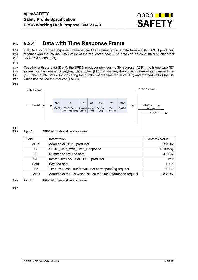
openSAFETY
Safety Profile Specification
EPSG Working Draft Proposal 304 V1.4.0
EPSG WDP 304 V-1-4-0.docx 47/191
5.2.4 Data with Time Response Frame 1174
The Data with Time Response Frame is used to transmit process data from an SN (SPDO producer) 1175
together with the internal timer value of the requested node. The data can be consumed by any other 1176
SN (SPDO consumer). 1177
1178
Together with the data (Data), the SPDO producer provides its SN address (ADR), the frame type (ID) 1179
as well as the number of payload data bytes (LE) transmitted, the current value of its internal timer 1180
(CT), the counter value for indicating the number of the time requests (TR) and the address of the SN 1181
which has issued the request (TADR). 1182
1183
SPDO Producer
ADR
SSADR
ID
SPDO_Data_
With_Time_Resp
LE
Payload
Length
CT
Internal
Time
Data
Payload
Data
TR
Time
Req.Cntr
TADR
DSADR
Indication
Indication
Indication
Request
SPDO Consumers
1184
Fig. 16. SPDO with data and time response 1185
Field Information Content / Value
ADR Address of SPDO producer SSADR
ID SPDO_Data_with_Time_Response 11010xxxb
LE Number of payload data 0 - 254
CT Internal time value of SPDO producer Time
Data Payload data Data
TR Time Request Counter value of corresponding request 0 - 63
TADR Address of the SN which issued the time information request DSADR
Tab. 11 SPDO with data and time response 1186
1187
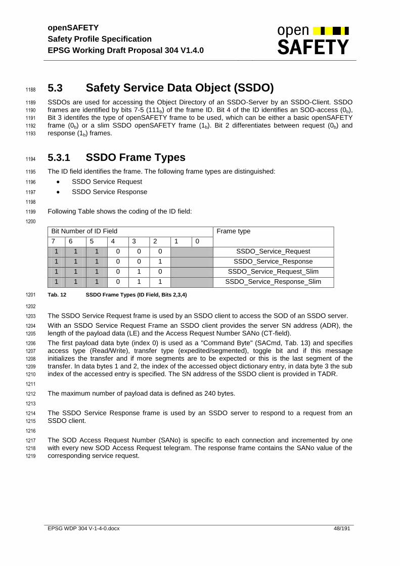
openSAFETY
Safety Profile Specification
EPSG Working Draft Proposal 304 V1.4.0
EPSG WDP 304 V-1-4-0.docx 48/191
5.3 Safety Service Data Object (SSDO) 1188
SSDOs are used for accessing the Object Directory of an SSDO-Server by an SSDO-Client. SSDO 1189
frames are identified by bits 7-5 (111b) of the frame ID. Bit 4 of the ID identifies an SOD-access (0b), 1190
Bit 3 identifes the type of openSAFETY frame to be used, which can be either a basic openSAFETY 1191
frame (0b) or a slim SSDO openSAFETY frame (1b). Bit 2 differentiates between request (0b) and 1192
response (1b) frames. 1193
5.3.1 SSDO Frame Types 1194
The ID field identifies the frame. The following frame types are distinguished: 1195
SSDO Service Request 1196
SSDO Service Response 1197
1198
Following Table shows the coding of the ID field: 1199
1200
Bit Number of ID Field Frame type
7 6 5 4 3 2 1 0
1 1 1 0 0 0 SSDO_Service_Request
1 1 1 0 0 1 SSDO_Service_Response
1 1 1 0 1 0 SSDO_Service_Request_Slim
1 1 1 0 1 1 SSDO_Service_Response_Slim
Tab. 12 SSDO Frame Types (ID Field, Bits 2,3,4) 1201
1202
The SSDO Service Request frame is used by an SSDO client to access the SOD of an SSDO server. 1203
With an SSDO Service Request Frame an SSDO client provides the server SN address (ADR), the 1204
length of the payload data (LE) and the Access Request Number SANo (CT-field). 1205
The first payload data byte (index 0) is used as a "Command Byte" (SACmd, Tab. 13) and specifies 1206
access type (Read/Write), transfer type (expedited/segmented), toggle bit and if this message 1207
initializes the transfer and if more segments are to be expected or this is the last segment of the 1208
transfer. In data bytes 1 and 2, the index of the accessed object dictionary entry, in data byte 3 the sub 1209
index of the accessed entry is specified. The SN address of the SSDO client is provided in TADR. 1210
1211
The maximum number of payload data is defined as 240 bytes. 1212
1213
The SSDO Service Response frame is used by an SSDO server to respond to a request from an 1214
SSDO client. 1215
1216
The SOD Access Request Number (SANo) is specific to each connection and incremented by one 1217
with every new SOD Access Request telegram. The response frame contains the SANo value of the 1218
corresponding service request. 1219

openSAFETY
Safety Profile Specification
EPSG Working Draft Proposal 304 V1.4.0
EPSG WDP 304 V-1-4-0.docx 49/191
Bit No. Name Value Meaning
0 Access Type bit 0 SOD Read Access
1 SOD Write Access
1 Reserved 1 bit 0 Reserved
2 Abort transfer bit 0 Successful transfer
1 Abort transfer
3 Segmentation bit 0 Expedited SOD access
1 Segmented SOD access
4 Toggle bit 0 This bit shall alternate for each subsequent segment and not change its value in case of a repeated transmission. The first segment shall have the toggle bit set to 0. The toggle bit shall be equal for the request and the response frame.
1
5 Initiate transfer bit 0 No initiate transfer
1 Initiate transfer
6 End segment transfer bit 0 More segments to transfer
1 No more segments to transfer
7 Block transfer 0 Normal transfer
1 Block transfer
Tab. 13 SOD Access Command (SACmd) – Bit coding 1220
1221
openSAFETY
Safety Profile Specification
EPSG Working Draft Proposal 304 V1.4.0
EPSG WDP 304 V-1-4-0.docx 50/191
5.3.2 SSDO Services and Protocols 1222
There are two types of SSDO services using different types of openSAFETY frames. The normal 1223
SSDO service using the basic openSAFETY frame may be used for all SSDO services. The slim 1224
SSDO service using the slim SSDO openSAFETY frame may only be used to download initializing 1225
data to a SN. The lack of having the data twice in the POWELINK safety frame must be compensated 1226
by verifying the data. This is done by only switching the SN to operational if the SOD CRC is correct. 1227
1228
The following SSDO services are defined: 1229
SSDO Download, which is subdivided into 1230
o SSDO Download Initiate 1231
o SSDO Download Segment 1232
1233
SSDO Upload, which is subdivided into 1234
o SSDO Upload Initiate 1235
o SSDO Upload Segment 1236
1237
SSDO Block Download, which is subdivided into 1238
o SSDO Block Download Initiate 1239
o SSDO Block Download Segment 1240
1241
SSDO Block Upload, which is subdivided into 1242
o SSDO Block Upload Initiate 1243
o SSDO Block Upload Segment 1244
1245
SSDO Abort 1246
1247
The block download/upload protocol is optional. Its advantage is that there are no response frames for 1248
the data segments. This results in less data traffic when transferring a big amount of data. To ensure 1249
that no overload is created, a inhibit time (minimum time between two segment telegrams) may be 1250
specified. If the block download/upload protocol is not implemented on a SSDO server, the SSDO 1251
client must use the segmented transfer protocol. 1252
1253
The following figures show the SSDO segmented, block and expedited download and upload 1254
protocols. 1255
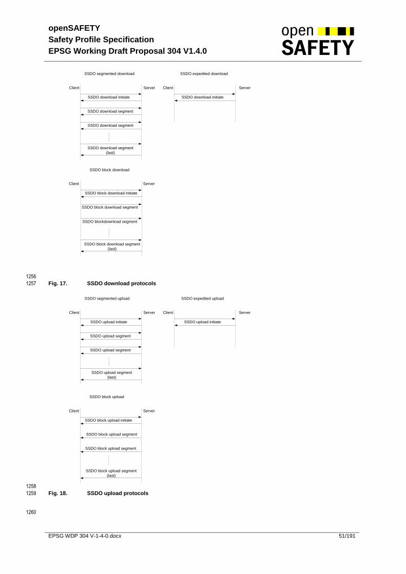
openSAFETY
Safety Profile Specification
EPSG Working Draft Proposal 304 V1.4.0
EPSG WDP 304 V-1-4-0.docx 51/191
Client Server Client Server
SSDO segmented download SSDO expedited download
SSDO download initiate
SSDO download segment
SSDO download segment
SSDO download segment
(last)
SSDO download initiate
SSDO block download
SSDO block download initiate
SSDO block download segment
SSDO blockdownload segment
SSDO block download segment
(last)
ServerClient
1256
Fig. 17. SSDO download protocols 1257
Client Server Client Server
SSDO segmented upload SSDO expedited upload
SSDO upload initiate
SSDO upload segment
SSDO upload segment
SSDO upload segment
(last)
SSDO upload initiate
Client Server
SSDO block upload
SSDO block upload initiate
SSDO block upload segment
SSDO block upload segment
SSDO block upload segment
(last)
1258
Fig. 18. SSDO upload protocols 1259
1260

openSAFETY
Safety Profile Specification
EPSG Working Draft Proposal 304 V1.4.0
EPSG WDP 304 V-1-4-0.docx 52/191
5.3.2.1 SSDO Download Initiate 1261
ADR
DSADR
ID
SSDO_Service_Request /
SSDO_Service_Request_Fast
LE
Payload
Length
CT
SANo
DB0
SACmd
TR
0
TADR
SSADR
IndicationRequest
Confirmation Response
DB1-2
Index
DB3
Sub-
Index
DB4-n
Payload Data
ADR
DSADR
ID
SSDO_Service_Response /
SSDO_Service_Response_Fast
LE
Payload
Length
CT
SANo
DB0
SACmd
TR
0
TADR
SSADR
DB1-2
Index
DB3
Sub-Index
SSDO Client SSDO Server
1262
Fig. 19. SSDO Download Initiate Protocol 1263
Request Frame
Field Information Content / Value
ADR Address of SSDO Server to be accessed DSADR
ID SSDO_Service_Request SSDO_Service_Request_Slim
111000xxb
111010xxb
LE Length of payload data 4 - 254
CT SOD Access Request number (SANo) 1 – 65535, 0 not allowed
DB0 SOD Access Command (SACmd) expedited or Segmented
00100001b or 00101001b
DB1, DB2 Index of SOD entry to be accessed 0 - 65535
DB3 Sub Index of SOD entry to be accessed 0 - 255
DB4 – DBn Payload data (In case of a segmented download, DB4-DB7 contains the data size of the payload data to be downloaded. If the data size is 0, the size is not indicated.)
Payload data
TR Not used 0
TADR Address of SSDO Client SSADR
1264
Response Frame
Field Information Content / Value
ADR Address of SSDO Client to be responded DSADR
ID SSDO_Service_Response SSDO_Service_Response_Slim
111001xxb
111011xxb
LE Length of payload data 4
CT Echo of SOD Access Request number 1 – 65535, 0 not allowed
DB0 SOD Access Command (SACmd) expedited or Segmented
00100001b or 00101001b
DB1, DB2 Index of SOD entry to be accessed 0 - 65535
DB3 Sub Index of SOD entry to be accessed 0 - 255
TR Not used 0
TADR Address of SSDO Server SSADR
Tab. 14 SSDO Download Initiate Protocol 1265

openSAFETY
Safety Profile Specification
EPSG Working Draft Proposal 304 V1.4.0
EPSG WDP 304 V-1-4-0.docx 53/191
5.3.2.2 SSDO Download Segment 1266
ADR
DSADR
ID
SSDO_Service_Request /
SSDO_Service_Request_Fast
LE
Payload
Length
CT
SANo
DB0
SACmd
TR
0
TADR
SSADR
IndicationRequest
Confirmation Response
DB1-n
Payload Data
ADR
DSADR
ID
SSDO_Service_Response /
SSDO_Service_Response_Fast
LE
Payload
Length
CT
SANo
DB0
SACmd
TR
0
TADR
SSADR
SSDO Client SSDO Server
1267
Fig. 20. SSDO Download Segment Protocol 1268
Request Frame
Field Information Content / Value
ADR Address of SSDO Server to be accessed DSADR
ID SSDO_Service_Request SSDO_Service_Request_Slim
111000xxb
111010xxb
LE Length of payload data 4 - 254
CT SOD Access Request number (SANo) 1 – 65535, 0 not allowed
DB0 SOD Access Command (SACmd) middle segment or end segment
000x1001b
or 010x1001b
DB1 – DBn Payload data Payload data
TR Not used 0
TADR Address of SSDO Client SSADR
1269
Response Frame
Field Information Content / Value
ADR Address of SSDO Client to be responded DSADR
ID SSDO_Service_Response SSDO_Service_Response_Slim
111001xxb
111011xxb
LE Length of payload data 4
CT Echo of SOD Access Request number 1 – 65535, 0 not allowed
DB0 SOD Access Command (SACmd) middle segment or end segment
000x1001b
or 010x1001b
TR Not used 0
TADR Address of SSDO Server SSADR
Tab. 15 SSDO Download Segment Protocol 1270
1271
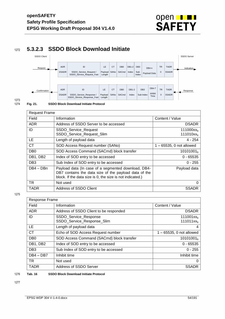
openSAFETY
Safety Profile Specification
EPSG Working Draft Proposal 304 V1.4.0
EPSG WDP 304 V-1-4-0.docx 54/191
5.3.2.3 SSDO Block Download Initiate 1272
ADR
DSADR
ID
SSDO_Service_Request /
SSDO_Service_Request_Fast
LE
Payload
Length
CT
SANo
DB0
SACmd
TR
0
TADR
SSADR
IndicationRequest
Confirmation Response
DB1-2
Index
DB3
Sub-
Index
DB4-n
Payload Data
ADR
DSADR
ID
SSDO_Service_Response /
SSDO_Service_Response_Fast
LE
Payload
Length
CT
SANo
DB0
SACmd
TR
0
TADR
SSADR
DB1-2
Index
DB3
Sub-Index
SSDO Client SSDO Server
DB4-7
Inhibit
Time
1273
Fig. 21. SSDO Block Download Initiate Protocol 1274
Request Frame
Field Information Content / Value
ADR Address of SSDO Server to be accessed DSADR
ID SSDO_Service_Request SSDO_Service_Request_Slim
111000xxb
111010xxb
LE Length of payload data 4 - 254
CT SOD Access Request number (SANo) 1 – 65535, 0 not allowed
DB0 SOD Access Command (SACmd) block transfer 10101001b
DB1, DB2 Index of SOD entry to be accessed 0 - 65535
DB3 Sub Index of SOD entry to be accessed 0 - 255
DB4 – DBn Payload data (In case of a segmented download, DB4-DB7 contains the data size of the payload data of the block. If the data size is 0, the size is not indicated.)
Payload data
TR Not used 0
TADR Address of SSDO Client SSADR
1275
Response Frame
Field Information Content / Value
ADR Address of SSDO Client to be responded DSADR
ID SSDO_Service_Response SSDO_Service_Response_Slim
111001xxb
111011xxb
LE Length of payload data 4
CT Echo of SOD Access Request number 1 – 65535, 0 not allowed
DB0 SOD Access Command (SACmd) block transfer 10101001b
DB1, DB2 Index of SOD entry to be accessed 0 - 65535
DB3 Sub Index of SOD entry to be accessed 0 - 255
DB4 – DB7 Inhibit time Inhibit time
TR Not used 0
TADR Address of SSDO Server SSADR
Tab. 16 SSDO Block Download Initiate Protocol 1276
1277
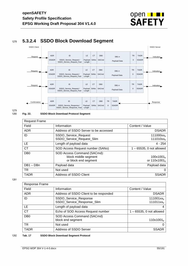
openSAFETY
Safety Profile Specification
EPSG Working Draft Proposal 304 V1.4.0
EPSG WDP 304 V-1-4-0.docx 55/191
5.3.2.4 SSDO Block Download Segment 1278
ADR
DSADR
ID
SSDO_Service_Request /
SSDO_Service_Request_Fast
LE
Payload
Length
CT
SANo
DB0
SACmd
TR
0
TADR
SSADR
IndicationRequest
Confirmation Response
DB1-n
Payload Data
ADR
DSADR
ID
SSDO_Service_Response /
SSDO_Service_Response_Fast
LE
Payload
Length
CT
SANo
DB0
SACmd
TR
0
TADR
SSADR
SSDO Client SSDO Server
ADR
DSADR
ID
SSDO_Service_Request /
SSDO_Service_Request_Fast
LE
Payload
Length
CT
SANo
DB0
SACmd
TR
0
TADR
SSADR
IndicationRequest DB1-n
Payload Data
ADR
DSADR
ID
SSDO_Service_Request /
SSDO_Service_Request_Fast
LE
Payload
Length
CT
SANo
DB0
SACmd
TR
0
TADR
SSADR
IndicationRequest DB1-n
Payload Data
1279
Fig. 22. SSDO Block Download Protocol Segment 1280
Request Frame
Field Information Content / Value
ADR Address of SSDO Server to be accessed DSADR
ID SSDO_Service_Request SSDO_Service_Request_Slim
111000xxb
111010xxb
LE Length of payload data 4 - 254
CT SOD Access Request number (SANo) 1 – 65535, 0 not allowed
DB0 SOD Access Command (SACmd): block middle segment or block end segment
100x1001b
or 110x1001b
DB1 – DBn Payload data Payload data
TR Not used 0
TADR Address of SSDO Client SSADR
1281
Response Frame
Field Information Content / Value
ADR Address of SSDO Client to be responded DSADR
ID SSDO_Service_Response SSDO_Service_Response_Slim
111001xxb
111011xxb
LE Length of payload data 4
CT Echo of SOD Access Request number 1 – 65535, 0 not allowed
DB0 SOD Access Command (SACmd) block end segment
110x1001b
TR Not used 0
TADR Address of SSDO Server SSADR
Tab. 17 SSDO Block Download Segment Protocol 1282

openSAFETY
Safety Profile Specification
EPSG Working Draft Proposal 304 V1.4.0
EPSG WDP 304 V-1-4-0.docx 56/191
5.3.2.5 SSDO Upload Initiate 1283
The initiate upload telegram is always expedited. Based on the response the SSDO client has to 1284
continue with expedited or segmented transfer. 1285
ADR
DSADR
ID
SSDO_Service_
Request
LE
Payload
Length
CT
SANo
DB0
SACmd
TR
0
TADR
SSADR
IndicationRequest
Confirmation Response
DB1-2
Index
DB3
Sub-Index
DB4-n
Data
ADR
DSADR
ID
SSDO_Service_
Response
LE
Payload
Length
CT
SANo
DB0
SACmd
TR
0
TADR
SSADR
DB1-2
Index
DB3
Sub-
Index
SSDO Client SSDO Server
1286
Fig. 23. SSDO Upload Initiate Protocol 1287
Request Frame
Field Information Content / Value
ADR Address of SSDO Server to be accessed DSADR
ID SSDO_Service_Request 111000xxb
LE Length of payload data 4
CT SOD Access Request number (SANo) 1 – 65535, 0 not allowed
DB0 SOD Access Command (SACmd) expedited 00100000b
DB1, DB2 Index of SOD entry to be accessed 0 - 65535
DB3 Sub Index of SOD entry to be accessed 0 - 255
TR Not used 0
TADR Address of SSDO Client SSADR
1288
Response Frame
Field Information Content / Value
ADR Address of SSDO Client to be responded DSADR
ID SSDO_Service_Response 111001xxb
LE Length of payload data 4-254
CT Echo of SOD Access Request number 1 – 65535, 0 not allowed
DB0 SOD Access Command (SACmd) expedited or Segmented
00100000b
or 00101000b
DB1, DB2 Index of SOD entry to be accessed 0 - 65535
DB3 Sub Index of SOD entry to be accessed 0 - 255
DB4 – DBn Payload data(In case of a segmented upload, DB4-DB7 contains the data size of the payload data of the block. If the data size is 0, the size is not indicated.)
Payload data
TR Not used 0
TADR Address of SSDO Server SSADR
Tab. 18 SSDO Upload Initiate Protocol 1289
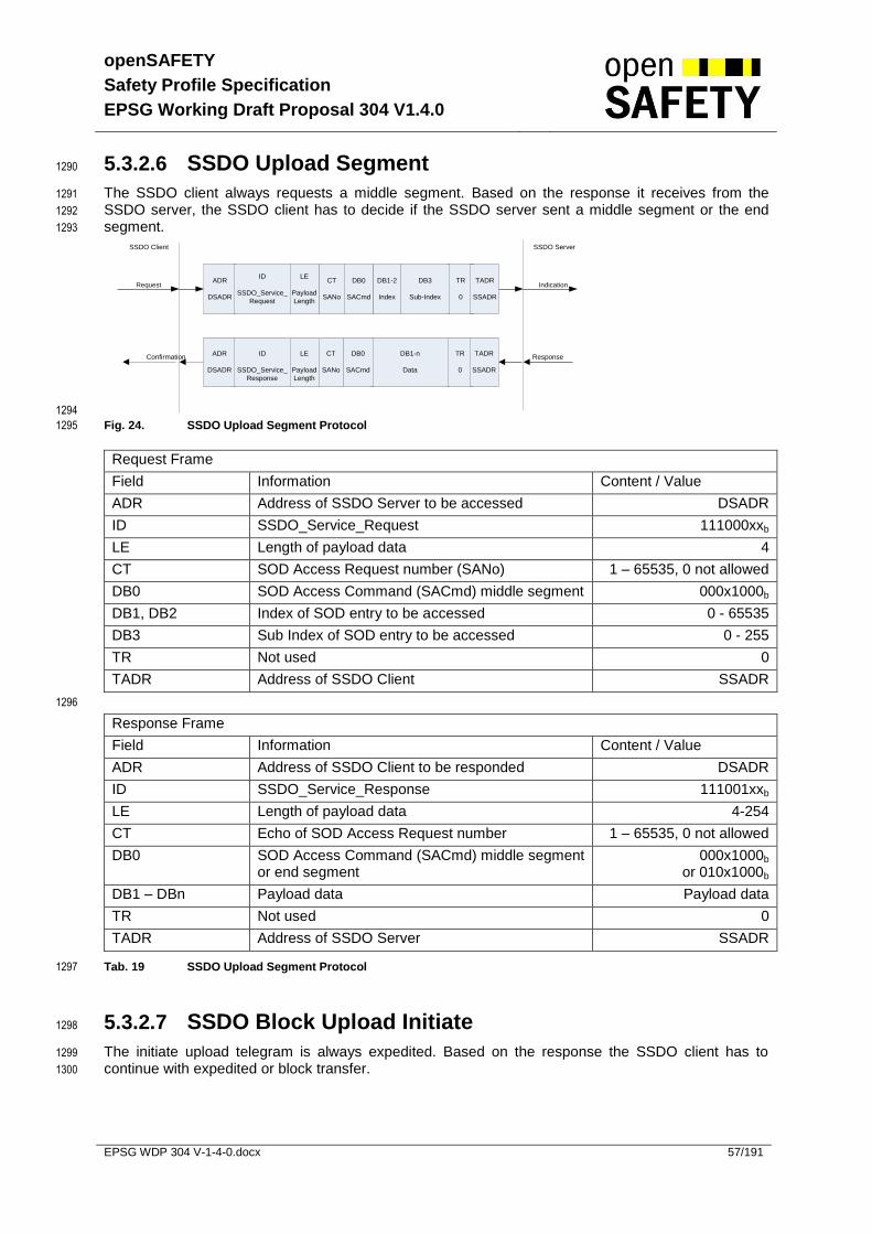
openSAFETY
Safety Profile Specification
EPSG Working Draft Proposal 304 V1.4.0
EPSG WDP 304 V-1-4-0.docx 57/191
5.3.2.6 SSDO Upload Segment 1290
The SSDO client always requests a middle segment. Based on the response it receives from the 1291
SSDO server, the SSDO client has to decide if the SSDO server sent a middle segment or the end 1292
segment. 1293
ADR
DSADR
ID
SSDO_Service_
Request
LE
Payload
Length
CT
SANo
DB0
SACmd
TR
0
TADR
SSADR
IndicationRequest
Confirmation Response
DB1-2
Index
DB3
Sub-Index
DB1-n
Data
ADR
DSADR
ID
SSDO_Service_
Response
LE
Payload
Length
CT
SANo
DB0
SACmd
TR
0
TADR
SSADR
SSDO Client SSDO Server
1294
Fig. 24. SSDO Upload Segment Protocol 1295
Request Frame
Field Information Content / Value
ADR Address of SSDO Server to be accessed DSADR
ID SSDO_Service_Request 111000xxb
LE Length of payload data 4
CT SOD Access Request number (SANo) 1 – 65535, 0 not allowed
DB0 SOD Access Command (SACmd) middle segment 000x1000b
DB1, DB2 Index of SOD entry to be accessed 0 - 65535
DB3 Sub Index of SOD entry to be accessed 0 - 255
TR Not used 0
TADR Address of SSDO Client SSADR
1296
Response Frame
Field Information Content / Value
ADR Address of SSDO Client to be responded DSADR
ID SSDO_Service_Response 111001xxb
LE Length of payload data 4-254
CT Echo of SOD Access Request number 1 – 65535, 0 not allowed
DB0 SOD Access Command (SACmd) middle segment or end segment
000x1000b or 010x1000b
DB1 – DBn Payload data Payload data
TR Not used 0
TADR Address of SSDO Server SSADR
Tab. 19 SSDO Upload Segment Protocol 1297
5.3.2.7 SSDO Block Upload Initiate 1298
The initiate upload telegram is always expedited. Based on the response the SSDO client has to 1299
continue with expedited or block transfer. 1300
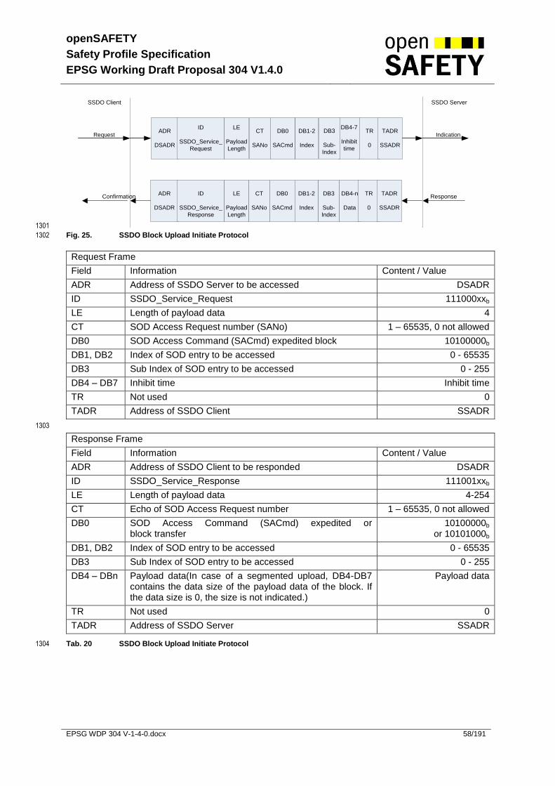
openSAFETY
Safety Profile Specification
EPSG Working Draft Proposal 304 V1.4.0
EPSG WDP 304 V-1-4-0.docx 58/191
ADR
DSADR
ID
SSDO_Service_
Request
LE
Payload
Length
CT
SANo
DB0
SACmd
TR
0
TADR
SSADR
IndicationRequest
Confirmation Response
DB1-2
Index
DB4-n
Data
ADR
DSADR
ID
SSDO_Service_
Response
LE
Payload
Length
CT
SANo
DB0
SACmd
TR
0
TADR
SSADR
DB1-2
Index
DB3
Sub-
Index
SSDO Client SSDO Server
DB4-7
Inhibit
time
DB3
Sub-
Index
1301
Fig. 25. SSDO Block Upload Initiate Protocol 1302
Request Frame
Field Information Content / Value
ADR Address of SSDO Server to be accessed DSADR
ID SSDO_Service_Request 111000xxb
LE Length of payload data 4
CT SOD Access Request number (SANo) 1 – 65535, 0 not allowed
DB0 SOD Access Command (SACmd) expedited block 10100000b
DB1, DB2 Index of SOD entry to be accessed 0 - 65535
DB3 Sub Index of SOD entry to be accessed 0 - 255
DB4 – DB7 Inhibit time Inhibit time
TR Not used 0
TADR Address of SSDO Client SSADR
1303
Response Frame
Field Information Content / Value
ADR Address of SSDO Client to be responded DSADR
ID SSDO_Service_Response 111001xxb
LE Length of payload data 4-254
CT Echo of SOD Access Request number 1 – 65535, 0 not allowed
DB0 SOD Access Command (SACmd) expedited or block transfer
10100000b
or 10101000b
DB1, DB2 Index of SOD entry to be accessed 0 - 65535
DB3 Sub Index of SOD entry to be accessed 0 - 255
DB4 – DBn Payload data(In case of a segmented upload, DB4-DB7 contains the data size of the payload data of the block. If the data size is 0, the size is not indicated.)
Payload data
TR Not used 0
TADR Address of SSDO Server SSADR
Tab. 20 SSDO Block Upload Initiate Protocol 1304

openSAFETY
Safety Profile Specification
EPSG Working Draft Proposal 304 V1.4.0
EPSG WDP 304 V-1-4-0.docx 59/191
5.3.2.8 SSDO Block Upload Segment 1305
The SSDO server sends the segments using the inhibit time it got with the initiate block upload 1306
telegram. Based on the response the SSDO client has to decide if a middle segment or the end 1307
segment was sent. 1308
Confirmation ResponseDB1-n
Data
ADR
DSADR
ID
SSDO_Service_
Response
LE
Payload
Length
CT
SANo
DB0
SACmd
TR
0
TADR
SSADR
SSDO Client SSDO Server
1309 1310
Fig. 26. SSDO Block Upload Segment Protocol 1311
Response Frame
Field Information Content / Value
ADR Address of SSDO Client to be responded DSADR
ID SSDO_Service_Response 111001xxb
LE Length of payload data 4-254
CT Echo of SOD Access Request number 1 – 65535, 0 not allowed
DB0 SOD Access Command (SACmd) middle segment or end segment
100x1000b or 110x1000b
DB1 – DBn Payload data Payload data
TR Not used 0
TADR Address of SSDO Server SSADR
Tab. 21 SSDO Block Upload Segment Protocol 1312
1313
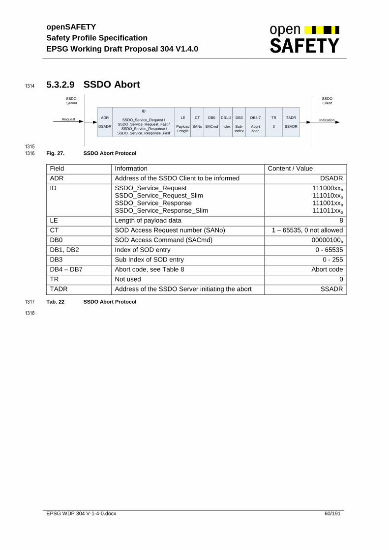
openSAFETY
Safety Profile Specification
EPSG Working Draft Proposal 304 V1.4.0
EPSG WDP 304 V-1-4-0.docx 60/191
5.3.2.9 SSDO Abort 1314
ADR
DSADR
ID
SSDO_Service_Request /
SSDO_Service_Request_Fast /
SSDO_Service_Response /
SSDO_Service_Response_Fast
LE
Payload
Length
CT
SANo
DB0
SACmd
TR
0
TADR
SSADR
IndicationRequest DB1-2
Index
DB3
Sub-
Index
SSDO
Server
SSDO
Client
DB4-7
Abort
code
1315
Fig. 27. SSDO Abort Protocol 1316
Field Information Content / Value
ADR Address of the SSDO Client to be informed DSADR
ID SSDO_Service_Request SSDO_Service_Request_Slim SSDO_Service_Response SSDO_Service_Response_Slim
111000xxb
111010xxb
111001xxb
111011xxb
LE Length of payload data 8
CT SOD Access Request number (SANo) 1 – 65535, 0 not allowed
DB0 SOD Access Command (SACmd) 00000100b
DB1, DB2 Index of SOD entry 0 - 65535
DB3 Sub Index of SOD entry 0 - 255
DB4 – DB7 Abort code, see Table 8 Abort code
TR Not used 0
TADR Address of the SSDO Server initiating the abort SSADR
Tab. 22 SSDO Abort Protocol 1317
1318

openSAFETY
Safety Profile Specification
EPSG Working Draft Proposal 304 V1.4.0
EPSG WDP 304 V-1-4-0.docx 61/191
The payload data of the abort frame consists of an error code which is defined in table 23. The abort 1319
code is encoded as UNSIGNED 32 value. 1320
1321
Abort code Description
0503 0000h Reserved
0504 0000h SSDO protocol timed out.
0504 0001h Client/server Command ID not valid or unknown.
0504 0002h Invalid block size.
0504 0003h Invalid sequence number.
0504 0004h Reserved
0504 0005h Out of memory.
0601 0000h Unsupported access to an object.
0601 0001h Attempt to read a write-only object.
0601 0002h Attempt to write a read-only object.
0602 0000h Object does not exist in the object dictionary.
0604 0041h Object cannot be mapped to the SPDO.
0604 0042h The number and length of the objects to be mapped would exceed SPDO length.
0604 0043h General parameter incompatibility.
0604 0047h General internal incompatibility in the device.
0606 0000h Access failed due to a hardware error.
0607 0010h Data type does not match, length of service parameter does not match
0607 0012h Data type does not match, length of service parameter too high
0607 0013h Data type does not match, length of service parameter too low
0609 0011h Sub-index does not exist.
0609 0030h Value range of parameter exceeded (only for write access).
0609 0031h Value of parameter written too high.
0609 0032h Value of parameter written too low.
0609 0036h Maximum value is less than minimum value.
0800 0000h General error.
0800 0020h Data cannot be transferred or stored to the application.
0800 0021h Data cannot be transferred or stored to the application because of local control.
0800 0022h Data cannot be transferred or stored to the application because of the present device state.
0800 0023 h Data cannot be transferred or stored to the application because application is busy.
Tab. 23 SSDO abort codes 1322
1323
All abort codes not listed in table 23 are reserved. 1324
1325

openSAFETY
Safety Profile Specification
EPSG Working Draft Proposal 304 V1.4.0
EPSG WDP 304 V-1-4-0.docx 62/191
5.4 Safety Network Management (SNMT) 1326
The openSAFETY Network Management is node oriented and follows a logical master-slave structure. 1327
The SNMT Master is given by a SCM or a configuration tool. 1328
1329
The following SNMT services are provided: 1330
UDID request 1331
Node address assignment 1332
Extended Services distinguished within the DB0 field, comprising the following services: 1333
o communication state control 1334
o node guarding 1335
o additional node address assignment 1336
5.4.1 SNMT Frame Types 1337
The ID field (bit 2-4) identifies the SNMT frame type. The following table shows the different SNMT 1338
frame types: 1339
1340
Bit Number of ID Field Frame Type Service
7 6 5 4 3 2 1 0
1 0 1 0 0 0 SNMT_Request_UDID UDID request
1 0 1 0 0 1 SNMT_Response_UDID
1 0 1 0 1 0 SNMT_Assign_SADR Node address assignment 1 0 1 0 1 1 SNMT_SADR_assigned
1 0 1 1 0 0 SNMT_Service_Request Extended Services
1 0 1 1 0 1 SNMT_Service_Response
1 0 1 1 1 1 SNMT_SN_reset_guarding_SCM Reset guarding timeout
Tab. 24 SNMT Frame Types (ID Field, Bits 2,3 and 4) 1341
1342

openSAFETY
Safety Profile Specification
EPSG Working Draft Proposal 304 V1.4.0
EPSG WDP 304 V-1-4-0.docx 63/191
5.4.2 SNMT Services and Protocols 1343
5.4.2.1 UDID Request 1344
The UDID Request service (Tab. 25) allows a SNMT Master to get the UDID of a specific SNMT 1345
Slave. For this, the SNMT Master sends the UDID Request to one specific SNMT Slave. The SNMT 1346
Slave has to reply even if the value within the ADR field does not match the SNs internal SADR. For 1347
example this may be happened if there was no prior SADR assignment to the SN. The TADR field of 1348
the response must contain the SADR of the request. In case the SN does not have a valid SADR and 1349
it would reply with its own SADR, the response cannot get assigned to the related request correctly. 1350
An error while executing the service is indicated with UDID “00-00-00-00-00-00” in the response. 1351
SNMT Master
ADR
DSADR
ID
SNMT_
Request_UDID
LE
Payload
Length
CT
0
DB0-n
No Data used
TR
0
TADR
SSADR
IndicationRequest
SNMT Slave
ADR
DSADR
ID
SNMT_
Response_UDID
LE
Payload
Length
CT
0
DB0-5
UDID
TR
0
TADR
SSADR
Confirmation
Response
1352
Fig. 28. SNMT UDID Request 1353
Request Frame
Field Information Content / Value
ADR Address of the SNMT Slave to be addressed DSADR
ID SNMT_Request_UDID 101000xxb
LE Length of payload data 0
CT Not used 0
TR Not used 0
TADR Address of SNMT Master SSADR
1354
Response Frame
Field Information Content / Value
ADR Address of SNMT Master DSADR
ID SNMT_Response_UDID 101001xxb
LE Length of payload data 6
CT Not used 0
DB0 – DB5 UDID of the SN UDID
TR Not used 0
TADR Address of SNMT Slave SSADR
Tab. 25 SNMT UDID Request 1355

openSAFETY
Safety Profile Specification
EPSG Working Draft Proposal 304 V1.4.0
EPSG WDP 304 V-1-4-0.docx 64/191
5.4.2.2 SADR assignment 1356
The SADR assignment service (Tab. 26) is used by a SNMT Master to set the SADR of a specific 1357
SNMT Slave. The service further assigns the openSAFETY domain number (SDN) to the SNMT 1358
Slave. The SDN is carried within the address field of the second sub frame using a logical XOR 1359
operation (see chapter 5.1.1). A SN may only send a response if the received UDID matches the SN’s 1360
own UDID. 1361
If the SDN/SADR requested by the SNMT Master can not be assigned, the SNMT Slave replies its 1362
current SDN/SADR and the SNMT Master can compare the replied SDN/SADR and UDID with the set 1363
SDN/SADR and UDID to see if the assignment was successful. Unsuccessful assignments can occure 1364
for example, if the nodes SDN/SADR is hard coded using a DIP switch and do not match to the SCM 1365
value. 1366
An error while executing the service is indicated with UDID “00-00-00-00-00-00” in the response. 1367
SNMT Master
ADR
DSADR
ID
SNMT_
Assign_SADR
LE
Payload
Length
CT
0
DDB0-5
UDID
TR
0
TADR
SSADR
IndicationRequest
SNMT Slave
ADR
DSADR
ID
SNMT_SADR
_Assigned
LE
Payload
Length
CT
0
DB0-5
UDID
TR
0
TADR
SSADR
Confirmation Response
1368
Fig. 29. SNMTSADR Assignment 1369
Request Frame
Field Information Content / Value
ADR Address of the SNMT Slave to be assigned DSADR
ID SNMT_Assign_SADR 101010xxb
LE Length of payload data 6
CT Not used 0
DB0 – DB5 UDID of the SN UDID
TR Not used 0
TADR Address of SNMT Master SSADR
1370
Response Frame
Field Information Content / Value
ADR Address of SNMT Master DSADR
ID SNMT_SADR_ Assigned 101011xxb
LE Length of payload data 6
CT Not used 0
DB0 – DB5 UDID of the SN UDID
TR Not used 0
TADR Address of SNMT Slave SSADR
Tab. 26 SNMTSADR Assignment 1371
1372

openSAFETY
Safety Profile Specification
EPSG Working Draft Proposal 304 V1.4.0
EPSG WDP 304 V-1-4-0.docx 65/191
5.4.2.3 Reset node guarding time 1373
The service Reset node guarding time (Tab. 27) is used by the SN to trigger a node guarding on the 1374
SCM. The SCM has to guard all SNs no matter if the SADR or SDN in the telegram are matching the 1375
SADR and SDN of the SCM or not. Due to the fact that the telegram is sent, before a SADR or SDN is 1376
assigned to the node, the telegram always is sent with SADR and SDN being 1. 1377
SNMT MasterSNMT Slave
ADR
1
ID
SNMT_SN_reset_
guarding_SCM
TADR
1
LE
0
CT
0
TR
0
ResponseIndication
1378
Fig. 30. SNMT SN reset guarding SCM 1379
Response Frame
Field Information Content / Value
ADR Address of SNMT Master 1
ID SNMT_SN_reset_guarding_SCM 101111xxb
LE Length of payload data 0
CT Not used 0
TR Not used 0
TADR Address of SNMT Slave 1
Tab. 27 SNMT SN reset guarding SCM 1380
1381

openSAFETY
Safety Profile Specification
EPSG Working Draft Proposal 304 V1.4.0
EPSG WDP 304 V-1-4-0.docx 66/191
5.4.3 SNMT Extended Services 1382
Extended SNMT Services are services which are specified by the ID field and the DB0 field of the 1383
openSAFETY frame (see Tab. 28). 1384
1385
Bit Number of DB0 SNMT Frame Type
7 6 5 4 3 2 1 0
Request Frames
0 0 0 0 0 0 0 0 SNMT_SN_set_to_PRE_OP
0 0 0 0 0 0 1 0 SNMT_SN_set_to_OP
0 0 0 0 0 1 0 0 SNMT_SCM_set_to_STOP
0 0 0 0 0 1 1 0 SNMT_SCM_set_to_OP
0 0 0 0 1 0 0 0 SNMT_SCM_guard_SN
0 0 0 0 1 0 1 0 SNMT_assign_additional_SADR
0 0 0 0 1 1 0 0 SNMT_SN_ACK
0 0 0 0 1 1 1 0 SNMT_assign_UDID_SCM
Response Frames
0 0 0 0 0 0 0 1 SNMT_SN_status_PRE_OP
0 0 0 0 0 0 1 1 SNMT_SN_status_OP
0 0 0 0 0 1 0 1 SNMT_assigned_additional_SADR
0 0 0 0 0 1 1 1 SNMT_SN_FAIL
0 0 0 0 1 0 0 1 SNMT_SN_busy
0 0 0 0 1 1 1 1 SNMT_assigned_UDID_SCM
Tab. 28 SNMT Frame Types specified by DB0 (SNMTCmd) 1386
1387

openSAFETY
Safety Profile Specification
EPSG Working Draft Proposal 304 V1.4.0
EPSG WDP 304 V-1-4-0.docx 67/191
5.4.3.1 SN set to preoperational 1388
The SN set to preoperational service (Tab. 29) is used to switch a SNMT Slave from the Operational 1389
to the Pre-Operational communication state. 1390
SNMT Master
ADR
DSADR
ID
SNMT_
Service_Request
LE
Payload
Length
CT
0
DB0
SNMT_set_to_
PRE_OP
TR
0
TADR
SSADR
IndicationRequest
SNMT Slave
ADR
DSADR
ID
SNMT_
Service_Resp.
TADR
SSADR
Confirmation
ResponseLE
Payload
Length
CT
0
DB0
SNMT_status_
PRE_OP
TR
0
1391
Fig. 31. SNMT SN put to Preoperational State 1392
Request Frame
Field Information Content / Value
ADR Address of the SNMT Slave to be accessed DSADR
ID SNMT Service Request 101100xxb
LE Length of payload data 1
CT Not used 0
DB0 SNMT_SN_set_to_PRE_OP 00000000b
TR Not used 0
TADR Address of SNMT Master SSADR
1393
Response Frame
Field Information Content / Value
ADR Address of SNMT Master DSADR
ID SNMT Service Response 101101xxb
LE Length of payload data 1
CT Not used 0
DB0 SNMT_SN_status_PRE_OP 00000001b
TR Not used 0
TADR Address of SNMT Slave SSADR
Tab. 29 SNMT SN put to Preoperational State 1394
1395

openSAFETY
Safety Profile Specification
EPSG Working Draft Proposal 304 V1.4.0
EPSG WDP 304 V-1-4-0.docx 68/191
5.4.3.2 SN set to operational 1396
The service SN set to operational (Tab. 30) is used to switch an SNMT Slave from Pre-Operational to 1397
Operational communication state. The response either is the information that the SN has entered the 1398
Operational state, or an error information which the SCM reports to its application. 1399
1400
ADR
DSADR
ID
SNMT_
Service_Request
LE
Payload
Length
CT
0
DB0
SNMT_
put_to_OP
TR
0
TADR
SSADR
IndicationRequest
ADR
SSADR
ID
SNMT_
Service_Resp.
TADR
DSADR
LE
Payload
Length
CT
0
DB0
SNMT_SN_status_OP
TR
0
DB1-4
Parameter
Timestamp
Confirmation Response
ADR
SSADR
ID
SNMT_
Service_Resp.
TADR
DSADR
LE
Payload
Length
CT
0
DB0
SNMT_SN_FAIL
TR
0
DB1
Error
Group
DB2
Error
Code
Confirmation ResponseADR
SSADR
ID
SNMT_
Service_Resp.
TADR
DSADR
LE
Payload
Length
CT
0
DB0
SNMT_SN_busy
TR
0
Response
SNMT SlaveSNMT Master
Confirmation
1401 1402
Fig. 32. SNMT set to Operational state 1403
Request Frame
Field Information Content / Value
ADR Address of SNMT Slave to be accessed DSADR
ID SNMT Service Request 101100xxb
LE Length of payload data 5
CT Not used 0
DB0 SNMT_SN_set_to_OP 00000010b
DB1 – DB4 Parameter timestamp See Chapter 5.6.4.7
TR Not used 0
TADR Address of SNMT Master SSADR
1404
1405
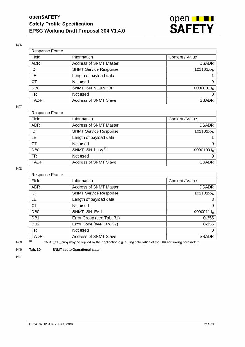
openSAFETY
Safety Profile Specification
EPSG Working Draft Proposal 304 V1.4.0
EPSG WDP 304 V-1-4-0.docx 69/191
1406
Response Frame
Field Information Content / Value
ADR Address of SNMT Master DSADR
ID SNMT Service Response 101101xxb
LE Length of payload data 1
CT Not used 0
DB0 SNMT_SN_status_OP 00000011b
TR Not used 0
TADR Address of SNMT Slave SSADR
1407
Response Frame
Field Information Content / Value
ADR Address of SNMT Master DSADR
ID SNMT Service Response 101101xxb
LE Length of payload data 1
CT Not used 0
DB0 SNMT_SN_busy (1)
00001001b
TR Not used 0
TADR Address of SNMT Slave SSADR
1408
Response Frame
Field Information Content / Value
ADR Address of SNMT Master DSADR
ID SNMT Service Response 101101xxb
LE Length of payload data 3
CT Not used 0
DB0 SNMT_SN_FAIL 00000111b
DB1 Error Group (see Tab. 31) 0-255
DB2 Error Code (see Tab. 32) 0-255
TR Not used 0
TADR Address of SNMT Slave SSADR (1)
SNMT_SN_busy may be replied by the application e.g. during calculation of the CRC or saving parameters 1409
Tab. 30 SNMT set to Operational state 1410
1411

openSAFETY
Safety Profile Specification
EPSG Working Draft Proposal 304 V1.4.0
EPSG WDP 304 V-1-4-0.docx 70/191
1412
Value Error Group
0 Device
1 Application
2 Parameter
3 Vendor specific
4 openSAFETY Stack
5 Additional Parameter needed
6-255 Reserved for future use
Tab. 31 SNMT_SN_FAIL Error Group 1413
1414
Value Error Code
0 Default
1-255 Vendor specific
Tab. 32 SNMT_SN_FAIL Error Code 1415
1416
5.4.3.2.1 Additional Parameter 1417
1418
An SN may implement additional parameter sets. If an SN returns an SN_FAIL commando with an 1419
ErrorGroup code of 5, the Error Code defines which set of additional parameters the node is 1420
requesting. 1421
In case of an erroneous transmission of the parameter set, the node will respond with a corresponding 1422
error code, indicating which parameter could not be transmitted correctly. 1423
1424
Error Code Description
0x00 – 0x0F Parameter sets 1-16
0xF0 – 0xFF Failure during reception of parameter set 1-16
Tab. 33 SNMT_SN_FAIL Error Code 1425
1426
1427
1428

openSAFETY
Safety Profile Specification
EPSG Working Draft Proposal 304 V1.4.0
EPSG WDP 304 V-1-4-0.docx 71/191
5.4.3.3 SNMT SN ack 1429
The service SN Acknowledge (Tab. 34) is used by the SCM to acknowledge a reported error (see 1430
5.4.3.2) to the SN. 1431
ADR
DSADR
ID
SNMT_
Service_Request
LE
Payload
Length
CT
0
DB0
SNMT_SN_
ACK
DB1
Error
Group
TADR
SSADR
IndicationRequest
SNMT Master SNMT Slave
TR
0
DB2
Error
Code
1432
Fig. 33. SNMT SN ack 1433
Response Frame
Field Information Content / Value
ADR Address of SNMT Slave to be accessed DSADR
ID SNMT Service Request 101100xxb
LE Length of payload data 3
CT Not used 0
DB0 SNMT_SN_ACK 00001100b
DB1 Error Group (see Tab. 31) 0-255
DB2 Error Code (see Tab. 32) 0-255
TR Not used 0
TADR Address of SNMT Master SSADR
Tab. 34 SNMT SN ack 1434
1435

openSAFETY
Safety Profile Specification
EPSG Working Draft Proposal 304 V1.4.0
EPSG WDP 304 V-1-4-0.docx 72/191
5.4.3.4 SCM set to stop 1436
The SCM set to stop service (Tab. 35) is used to switch an SCM off (from Operational to Stopped 1437
communication state) for system configuration by means of an external tool. 1438
ADR
DSADR
ID
SNMT_
Service_Request
LE
Payload
Length
CT
0
DB0
SNMT_SCM
set_to_STOP
TR
0
TADR
SSADR
IndicationRequest
Tool SCM
1439
Fig. 34. SNMT SCM put to stop state 1440
Field Information Content / Value
ADR Address of the SCM to be accessed DSADR
ID SNMT Service Request 101100xxb
LE Length of payload data 1
CT Not used 0
DB0 SNMT_SCM_set_to_STOP 00000100b
TR Not used 0
TADR Address of the TOOL SSADR
Tab. 35 SNMT SCM put to stop state 1441
1442

openSAFETY
Safety Profile Specification
EPSG Working Draft Proposal 304 V1.4.0
EPSG WDP 304 V-1-4-0.docx 73/191
5.4.3.5 SCM set to operational 1443
The SCM set to operational service (Tab. 36) is used to switch the SCM from Stopped to Operational 1444
communication state. This service can be applied after completion of the configuration by means an 1445
external tool. 1446
ADR
DSADR
ID
SNMT_
Service_Request
LE
Payload
Length
CT
0
DB0
SNMT_SCM
set_to_OP
TR
0
TADR
SSADR
IndicationRequest
Tool SCM
1447
Fig. 35. SNMT SCM put to operational state 1448
Field Information Content / Value
ADR Address of the SCM to be accessed DSADR
ID SNMT_Service_Request 101100xxb
LE Length of payload data 1
CT Not used 0
DB0 SNMT_SCM_set_to_OP 00000110b
TR Not used 0
TADR Address of the TOOL SSADR
Tab. 36 SNMT SCM put to operational state 1449
1450

openSAFETY
Safety Profile Specification
EPSG Working Draft Proposal 304 V1.4.0
EPSG WDP 304 V-1-4-0.docx 74/191
5.4.3.6 Node Guarding 1451
The node guarding service (Tab. 37) is used to guard a SN in Operational communication state. The 1452
SN responds with its status. If a SN does not receive a SNMT_SCM_guard_SN frame within its 1453
lifetime, it switches back to Pre-Operational. Signaling a lost request or response to the application is 1454
vendor specific. 1455
SNMT Master
ADR
DSADR
ID
SNMT_
Service_Request
LE
Payload
Length
CT
0
DB0
SNMT_SCM_
Guard_SN
TR
0
TADR
SSADR
IndicationRequest
SNMT Slave
ADR
DSADR
ID
SNMT_
Service_Resp.
TADR
SSADR
LE
Payload
Length
CT
0
DB0
SNMT_status_
PRE_OP or OP
TR
0
Confirmation Response
1456
Fig. 36. SNMT SCM guard SN 1457
Request Frame
Field Information Content / Value
ADR Address of SNMT Slave to be accessed DSADR
ID SNMT Service Request 101100xxb
LE Length of payload data 1
CT Not used 0
DB0 SNMT_SCM_guard_SN 00001000b
TR Not used 0
TADR Address of SNMT Master SSADR
1458
Response Frame
Field Information Content / Value
ADR Address of SNMT Master DSADR
ID SNMT Service Response 101101xxb
LE Length of payload data 1
CT Not used 0
DB0 SNMT_SN_status_PRE_OP
or SNMT_SN_status_OP
00000001b
or 00000011b
TR Not used 0
TADR Address of SNMT Slave SSADR
Tab. 37 SNMT SCM guard SN 1459
1460
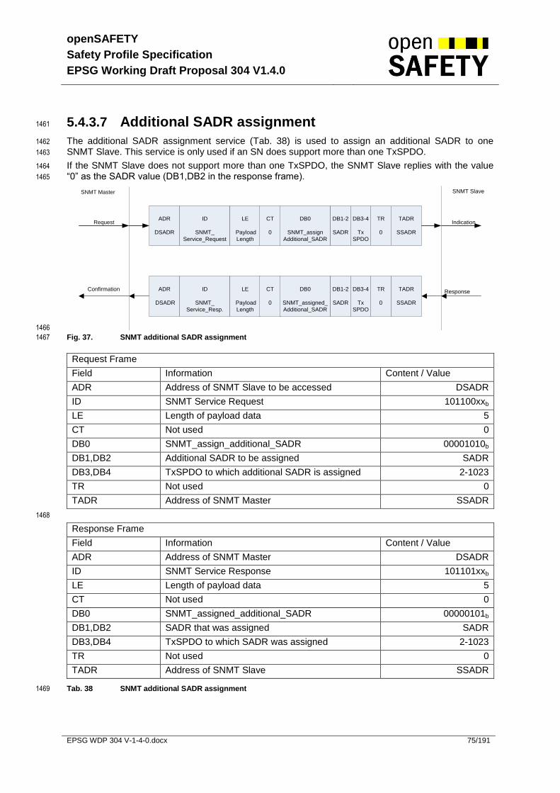
openSAFETY
Safety Profile Specification
EPSG Working Draft Proposal 304 V1.4.0
EPSG WDP 304 V-1-4-0.docx 75/191
5.4.3.7 Additional SADR assignment 1461
The additional SADR assignment service (Tab. 38) is used to assign an additional SADR to one 1462
SNMT Slave. This service is only used if an SN does support more than one TxSPDO. 1463
If the SNMT Slave does not support more than one TxSPDO, the SNMT Slave replies with the value 1464
“0” as the SADR value (DB1,DB2 in the response frame). 1465
SNMT Master
ADR
DSADR
ID
SNMT_
Service_Request
LE
Payload
Length
CT
0
DB0
SNMT_assign
Additional_SADR
TR
0
TADR
SSADR
IndicationRequest
SNMT Slave
ADR
DSADR
ID
SNMT_
Service_Resp.
TADR
SSADR
LE
Payload
Length
CT
0
DB0
SNMT_assigned_
Additional_SADR
TR
0
Confirmation Response
DB1-2
SADR
DB3-4
Tx
SPDO
DB1-2
SADR
DB3-4
Tx
SPDO
1466
Fig. 37. SNMT additional SADR assignment 1467
Request Frame
Field Information Content / Value
ADR Address of SNMT Slave to be accessed DSADR
ID SNMT Service Request 101100xxb
LE Length of payload data 5
CT Not used 0
DB0 SNMT_assign_additional_SADR 00001010b
DB1,DB2 Additional SADR to be assigned SADR
DB3,DB4 TxSPDO to which additional SADR is assigned 2-1023
TR Not used 0
TADR Address of SNMT Master SSADR
1468
Response Frame
Field Information Content / Value
ADR Address of SNMT Master DSADR
ID SNMT Service Response 101101xxb
LE Length of payload data 5
CT Not used 0
DB0 SNMT_assigned_additional_SADR 00000101b
DB1,DB2 SADR that was assigned SADR
DB3,DB4 TxSPDO to which SADR was assigned 2-1023
TR Not used 0
TADR Address of SNMT Slave SSADR
Tab. 38 SNMT additional SADR assignment 1469

openSAFETY
Safety Profile Specification
EPSG Working Draft Proposal 304 V1.4.0
EPSG WDP 304 V-1-4-0.docx 76/191
5.4.3.8 UDID of SCM assignment 1470
The UDID of SCM assignment service (Tab. 39) is used to assign the UDID of the SCM to the SNMT 1471
Slave. The UDID of the SCM is coded in all SPDOs and SSDOs. Therefore the SNMT Slave needs it 1472
to decode those telegrams. 1473
An error while executing the service is indicated whit UDID “00-00-00-00-00-00” in the response. 1474
SNMT Master
ADR
DSADR
ID
SNMT_
Service_Request
LE
Payload
Length
CT
0
DB0
SNMT_assign
UDID_of_SCM
TR
0
TADR
SSADR
IndicationRequest
SNMT Slave
ADR
DSADR
ID
SNMT_
Service_Resp.
TADR
SSADR
LE
Payload
Length
CT
0
DB0
SNMT_assigned_
UDID_of_SCM
TR
0
Confirmation Response
DB1-6
UDID of
SCM
DB1-6
UDID of
SCM
1475
Fig. 38. UDID of SCM assignment 1476
Request Frame
Field Information Content / Value
ADR Address of SNMT Slave to be accessed DSADR
ID SNMT Service Request 101100xxb
LE Length of payload data 7
CT Not used 0
DB0 SNMT_assign_UDID_of_SCM 00001110b
DB1- DB6 UDID of the SCM UDID
TR Not used 0
TADR Address of SNMT Master SSADR
1477
Response Frame
Field Information Content / Value
ADR Address of SNMT Master DSADR
ID SNMT Service Response 101101xxb
LE Length of payload data 7
CT Not used 0
DB0 SNMT_assigned_UDID_of_SCM 00001111b
DB1- DB6 UDID of the SCM UDID
TR Not used 0
TADR Address of SNMT Slave SSADR
Tab. 39 UDID of SCM assignment 1478
1479

openSAFETY
Safety Profile Specification
EPSG Working Draft Proposal 304 V1.4.0
EPSG WDP 304 V-1-4-0.docx 77/191
5.5 Data Types and Encoding Rules 1480
5.5.1 General Description 1481
To be able to exchange data across the network, the format of this data and its meaning have to be 1482
known by the producer and consumer(s). This specification models this according to the concept of 1483
data types. 1484
1485
The encoding rules define the representation of values, of data types and the network transfer syntax 1486
for the representations. Values are represented as bit sequences. Bit sequences are transferred in 1487
sequences of octets (bytes). For numerical data types, the encoding is little endian style as shown in 1488
Tab. 40. 1489
1490
Applications often require data types beyond the basic data types. By using the compound data type 1491
mechanism, the list of available data types can be extended. Some general extended data types are 1492
defined as “Visible String” for example (see 5.5.6.2). The compound data types are a means to 1493
implement user defined “DEFTYPES” in the terminology of this specification and not “DEFSTRUCTS”. 1494
5.5.2 Data Type Definitions 1495
A data type determines a relation between values and encoding for data of that type. Names are 1496
assigned to data types in their type definitions. The syntax of data and data type definitions is as 1497
follows (see EN 61131-3). 1498
data_definition ::= type_name data_name 1499
type_definition ::= constructor type_name 1500
constructor ::= compound_constructor | 1501
basic_constructor 1502
compound_constructor ::= array_constructor | 1503
structure_constructor 1504
array_constructor ::= ‘ARRAY’ ‘[‘ length ‘]’ ‘OF’ type_name 1505
structure_constructor ::= ‘STRUCT’ ‘OF’ component_list 1506
component_list ::= component { ‘,’ component } 1507
component ::= type_name component_name 1508
basic_constructor ::= ‘BOOLEAN’ | 1509
‘VOID’ bit_size | 1510
‘INTEGER’ bit_size | 1511
‘UNSIGNED’ bit_size | 1512
‘REAL32’ | 1513
‘REAL64’ | 1514
‘NIL’ 1515
bit_size ::= ‘1’ | ‘2’ | <...> | ‘64’ 1516
length ::= positive_integer 1517
data_name ::= symbolic_name 1518
type_name ::= symbolic_name 1519
component_name ::= symbolic_name 1520
symbolic_name ::= letter { [ ‘_’ ] ( letter | digit ) } 1521
positive_integer ::= ( ‘1’ | ‘2’ | <...> | ‘9’ ) { digit } 1522
letter ::= ‘A’ | ‘B’ | <...> | ‘Z’ | ‘a’ | ‘b’ | <...> | ‘z’ 1523
digit ::= ‘0’ | ‘1’ | <...> | ‘9’ 1524
Recursive definitions are not allowed. 1525
1526
The data type defined by type_definition is called basic (res.~compound) when the constructor is 1527
basic_constructor (res. compound_constructor). 1528
openSAFETY
Safety Profile Specification
EPSG Working Draft Proposal 304 V1.4.0
EPSG WDP 304 V-1-4-0.docx 78/191
5.5.3 Bit Sequences 1529
5.5.3.1 Definition of Bit Sequences 1530
A bit can take the values 0 or 1. 1531
A bit sequence b is an ordered set of 0 or more bits. 1532
If a bit sequence b contains more than 0 bits, they are denoted as bj, j > 0. 1533
Let b0, ..., bn-1 be bits, n a positive integer. Then 1534
1535
b = b0 b1 ... bn-1 1536
is called a bit sequence of length |b| = n. 1537
1538
The empty bit sequence of length 0 is denoted ε. 1539
Examples: 10110100, 1, 101, etc. are bit sequences. 1540
1541
The inversion operator (¬) on bit sequences assigns to a bit sequence 1542
b = b0 b1 ... bn-1 1543
the bit sequence 1544
¬b = ¬b0 ¬b1 ... ¬bn-1 1545
Here ¬0 = 1 and ¬1 = 0 on bits. 1546
1547
The basic operation on bit sequences is concatenation. 1548
Let a = a0 ... am-1 and b = b0 ... bn-1 be bit sequences. 1549
Then the concatenation of a and b, denoted ab, is 1550
ab = a0 ... am-1 b0 ... bn-1 1551
Example: (10)(111) = 10111 is the concatenation of 10 and 111. 1552
1553
The following holds for arbitrary bit sequences a and b: 1554
|ab| = |a| + |b| 1555
and 1556
1557
1558

openSAFETY
Safety Profile Specification
EPSG Working Draft Proposal 304 V1.4.0
EPSG WDP 304 V-1-4-0.docx 79/191
5.5.3.2 Transfer Syntax for Bit Sequences 1559
For transmission across the network, a bit sequence is reordered into a sequence of octets. Here and 1560
in the following, hexadecimal notation is used for octets. Let b = b0...bn-1 be a bit sequence with 1561
n<64. 1562
1563
Denote k a non-negative integer such that 8(k - 1) < n < 8k. Then b is transferred in k octets 1564
assembled as shown in Tab. 40. The bits bi, i > n of the highest numbered octet are “do not care bits”. 1565
1566
Octet 1 is transmitted first and octet k is transmitted last. The bit order within the octet is network 1567
specific and not within the scope of this document. 1568
1569
octet number 1. 2. …. k.
b0 - b7 b8 - b15 .. …. b8k-8 - b8k-1
Tab. 40 Transfer Syntax for Bit Sequences 1570
Example: 1571
Bit 8,9 Bit 4-7 Bit 0-3
10b 0001b 1100b
2h 1h Ch
=21Ch
1572
The bit sequence b = b0 .. b9 = 0011 1000 01 represents an UNSIGNED10 with the value 1573
21Ch and is transferred in two octets: 1574
First 1Ch and then 02h. 1575
Note: The bit sequence within the octet is network specific and not specified by this document. 1576
5.5.4 Basic Data Types 1577
For basic data types, “type_name” equals the literal string of the associated constructor (aka 1578
symbolic_name), e.g., 1579
BOOLEAN BOOLEAN 1580
1581
is the type definition for the BOOLEAN data type. 1582
5.5.4.1 NIL 1583
Data of basic data type NIL is represented by ε. 1584
5.5.4.2 Boolean 1585
Data of basic data type BOOLEAN can have the values TRUE or FALSE. 1586
The values are represented as bit sequences of length 1. The value TRUE (res. FALSE) is 1587
represented by the bit sequence 1 (res. 0). 1588
1589

openSAFETY
Safety Profile Specification
EPSG Working Draft Proposal 304 V1.4.0
EPSG WDP 304 V-1-4-0.docx 80/191
5.5.4.3 Void 1590
Data of basic data type VOIDn is represented as bit sequences of length n bits. 1591
The value of data of type VOIDn is undefined. The bits in the sequence of data of type VOIDn must 1592
either be specified explicitly or else marked “do not care”. 1593
Data of type VOIDn is useful for reserved fields and for aligning components of compound values on 1594
octet boundaries. 1595
5.5.4.4 Unsigned Integer 1596
Data of basic data type UNSIGNEDn has non-negative integers values. 1597
The value range is 0, 2n
-1. The data is represented as bit sequences of length n. 1598
1599
The bit sequence 1600
b = b0 ...bn-1 1601
is assigned the value 1602
UNSIGNEDn(b) = bn-1 2n-1
+ ...+ b1 21
+ b0 20
1603
Note that the bit sequence starts on the left with the least significant byte. 1604
Example: The value 266 = 10Ah with data type UNSIGNED16 is transferred in two octets 1605
across the bus, first 0Ah and then 01h. 1606
1607
The following UNSIGNEDn data types are transferred as shown below: 1608
octet number 1. 2. 3. 4. 5. 6. 7. 8.
UNSIGNED8 b7 .. b0
UNSIGNED16 b7 .. b0 b15 .. b8
UNSIGNED24 b7 .. b0 b15 .. b8 b23 .. b16
UNSIGNED32 b7 .. b0 b15 .. b8 b23 .. b16 b31 .. b24
UNSIGNED40 b7 .. b0 b15 .. b8 b23 .. b16 b31 .. b24 b39 .. b32
UNSIGNED48 b7 .. b0 b15 .. b8 b23 .. b16 b31 .. b24 b39 .. b32 b47 .. b40
UNSIGNED56 b7 .. b0 b15 .. b8 b23 .. b16 b31 .. b24 b39 .. b32 b47 .. b40 b55 .. b48
UNSIGNED64 b7 .. b0 b15 .. b8 b23 .. b16 b31 .. b24 b39 .. b32 b47 .. b40 b55 .. b48 b63 .. b56
Tab. 41 Transfer syntax for data type UNSIGNEDn 1609
1610

openSAFETY
Safety Profile Specification
EPSG Working Draft Proposal 304 V1.4.0
EPSG WDP 304 V-1-4-0.docx 81/191
5.5.4.5 Signed Integer 1611
Data of basic data type INTEGERn has integer values. The value range is -2n-1
, ..., 2n-1
-1. 1612
The data is represented as bit sequences of length n. The bit sequence 1613
b = b0 .. bn-1 1614
is assigned the value 1615
INTEGERn(b) = bn-2 2n-2
+ ...+ b1 21
+ b0 20
if bn-1 = 0 1616
and, performing two’s complement arithmetic, 1617
INTEGERn(b) = - INTEGERn(^b) - 1 if bn-1 = 1 1618
Note that the bit sequence starts on the left with the least significant bit. 1619
1620
Example: The value –266 = FEF6h with data type INTEGER16 is transferred in two octets 1621
across the bus, first F6h and then FEh. 1622
The following INTEGERn data types are transferred as shown below: 1623
octet number 1. 2. 3. 4. 5. 6. 7. 8.
INTEGER8 b7 .. b0
INTEGER16 b7 .. b0 b15 .. b8
INTEGER24 b7 .. b0 b15 .. b8 b23 .. b16
INTEGER32 b7 .. b0 b15 .. b8 b23 .. b16 b31 .. b24
INTEGER40 b7 .. b0 b15 .. b8 b23 .. b16 b31 .. b24 b39 .. b32
INTEGER48 b7 .. b0 b15 .. b8 b23 .. b16 b31 .. b24 b39 .. b32 b47 .. b40
INTEGER56 b7 .. b0 b15 .. b8 b23 .. b16 b31 .. b24 b39 .. b32 b47 .. b40 b55 .. b48
INTEGER64 b7 .. b0 b15 .. b8 b23 .. b16 b31 .. b24 b39 .. b32 b47 .. b40 b55 .. b48 b63 .. b56
Fig. 39. Transfer syntax for data type INTEGERn 1624
1625

openSAFETY
Safety Profile Specification
EPSG Working Draft Proposal 304 V1.4.0
EPSG WDP 304 V-1-4-0.docx 82/191
5.5.4.6 Floating Point Numbers 1626
Data of basic data types REAL32 and REAL64 have real numbers values. 1627
The data type REAL32 is represented as bit sequence of length 32. The encoding of values follows 1628
the IEEE 754-1985 Standard for single precision floating point number. The data type REAL64 is 1629
represented as bit sequence with the length of 64 bits. The encoding of values follows the IEEE 754-1630
1985 Standard for double precision floating-point numbers. 1631
1632
A bit sequence of length 32 either has a value (finite real number) or is NaN (not a number). 1633
The bit sequence 1634
b = b0 … b31 1635
is assigned the value (finite non-zero number) 1636
REAL32(b) = (-1)S
2E - 127
(1 + F) 1637
Here 1638
S = b31 is the sign. 1639
E = b30 27
+ …+ b23 20
, 0 < E < 255, is the un-biased exponent. 1640
F = 2-23
(b22 222
+ …+ b1 21
+ b0 20
) is the fractional part of the number. 1641
E = 0 is used to represent ± 0. E = 255 is used to represent infinities and NaN’s. 1642
Note that the bit sequence starts on the left with the least significant bit. 1643
Example: 1644
6.25 = 2E -127
(1 + F) with 1645
E =129 =27
+20
and 1646
F = 2-1
+2-4
= 2-23
(222
+219
) hence the number is represented as: 1647
S E F
b31 b30 .. b23 b22 .. b0
0 100 0000 1 100 1000 0000 0000 0000
1648
6.25 = b0 .. b31 = 0000 0000 0000 0000 0001 0011 0000 0010 1649
1650
It is transferred in the following order: 1651
octet number 1. 2. 3. 4.
REAL32 00h 00h C8h 40h
INTEGER32 b7 .. b0 b15 .. b8 b23 .. b16 b31 .. b24
Fig. 40. Transfer syntax of data type REAL32 1652
1653

openSAFETY
Safety Profile Specification
EPSG Working Draft Proposal 304 V1.4.0
EPSG WDP 304 V-1-4-0.docx 83/191
5.5.5 Compound Data Types 1654
Type definitions of compound data types expand to a unique list of type definitions involving only basic 1655
data types. Correspondingly, data of compound type ´type_name´ represents ordered lists of 1656
component data named ´component_name_i´ of basic type ´basic_type_i´. 1657
1658
Compound data type constructors are ARRAY and STRUCT OF. 1659
STRUCT OF 1660
basic_type_1 component_name_1, 1661
basic_type_2 component_name_2, 1662
… … 1663
basic_type_N component_name_N 1664
type_name 1665
ARRAY [ length ] OF basic_type type_name 1666
1667
The bit sequence representing data of compound type is obtained by concatenating the bit sequences 1668
representing the component data. 1669
Assume that the components ´component_name_i´ are represented by their bit sequences 1670
b(i), for i = 1,…,N 1671
Then the compound data is represented by the concatenated sequence 1672
b0(1) .. bn-1(1) .. bn-1(N). 1673
1674
Example: 1675
Consider the data type 1676
STRUCT OF 1677
INTEGER10 x, 1678
UNSIGNED5 u 1679
New Data 1680
Assume x = - 423 = 259h and u = 30 = 1Eh. Let b(x) and b(u) denote the bit sequences 1681
representing the values of x and u, respectively. Then: 1682
b(x) = b0(x) .. b9(x) = 1001101001 1683
b(u) = b0(u) .. b4(u) = 01111 1684
b(xu) = b(x) b(u) = b0(xu) .. b14(xu) = 1001101001 01111 1685
The value of the structure is transferred with two octets, first 59h and then 7Ah. 1686
5.5.6 Extended Data Types 1687
The extended data types consist of the basic data types and the compound data types defined in the 1688
following subsections. 1689
5.5.6.1 Octet String 1690
The data type OCTET_STRINGlength is defined below; length is the length of the octet string. 1691
ARRAY [ length ] OF UNSIGNED8 OCTET_STRINGlength 1692

openSAFETY
Safety Profile Specification
EPSG Working Draft Proposal 304 V1.4.0
EPSG WDP 304 V-1-4-0.docx 84/191
5.5.6.2 Visible String 1693
The data type VISIBLE_STRINGlength is defined below. Admissible values of data with type 1694
VISIBLE_CHAR are 0h and the range from 20h to 7Eh. The data is interpreted as ISO 646-1973(E) 1695
7-bit coded characters. length is the “length” of the visible string. 1696
UNSIGNED8 VISIBLE_CHAR 1697
ARRAY [ length ] OF VISIBLE_CHAR VISIBLE_STRINGlength 1698
0h is not necessary to terminate the string. 1699
5.5.6.3 Unicode String 1700
The data type UNICODE_STRINGlength is defined below; length is the length of the unicode string. 1701
ARRAY [ length ] OF UNSIGNED16 UNICODE_STRINGlength 1702
5.5.6.4 Domain 1703
Domains can be used to transfer an arbitrarily sized block of data from a client to a server and vice-1704
versa. The content of a data block is application specific and does not fall within the scope of this 1705
document. 1706
1707

openSAFETY
Safety Profile Specification
EPSG Working Draft Proposal 304 V1.4.0
EPSG WDP 304 V-1-4-0.docx 85/191
5.6 Object Dictionary (SOD) 1708
This section contains the openSAFETY Object Dictionary structure and entries which are common to 1709
all devices. 1710
5.6.1 Data Type Entry Specification 1711
Index Object Name
0001h DEFTYPE BOOLEAN
0002h DEFTYPE INTEGER8
0003h DEFTYPE INTEGER16
0004h DEFTYPE INTEGER32
0005h DEFTYPE UNSIGNED8
0006h DEFTYPE UNSIGNED16
0007h DEFTYPE UNSIGNED32
0008h DEFTYPE REAL32
0009h DEFTYPE VISIBLE_STRING
000Ah DEFTYPE OCTET_STRING
000Bh DEFTYPE UNICODE_STRING
000Ch reserved
000Dh reserved
000Eh reserved
000Fh DEFTYPE DOMAIN
0010h DEFTYPE INTEGER24
0011h DEFTYPE REAL64
0012h DEFTYPE INTEGER40
0013h DEFTYPE INTEGER48
0014h DEFTYPE INTEGER56
0015h DEFTYPE INTEGER64
0016h DEFTYPE UNSIGNED24
0017h reserved
0018h DEFTYPE UNSIGNED40
0019h DEFTYPE UNSIGNED48
001Ah DEFTYPE UNSIGNED56
001Bh DEFTYPE UNSIGNED64
001Ch – 001Fh reserved
0020h DEFSTRUCT SSDO_LifeGuardRecord_TYPE
0021h DEFSTRUCT SINF_DevVendorInfoRecord_TYPE
0022h DEFSTRUCT SCOM_CommonCommParamRecord_TYPE
0023h DEFSTRUCT SSDO_CommParamRecord_TYPE
0024h DEFSTRUCT SNMT_CommParamRecord_TYPE
0025h DEFSTRUCT SPDO_RxCommParamRecord_TYPE
0026h DEFSTRUCT SPDO_TxCommParamRecord_TYPE
0027h DEFSTRUCT SSCM_SADRDVIListRecord_TYPE
0028h DEFSTRUCT SSCM_UDIDSADRListRecord_TYPE
0029h DEFSTRUCT SSCM_SpecificParametersRecord_TYPE
002Ah– 003Fh reserved
Tab. 42 Object Dictionary Data Types 1712
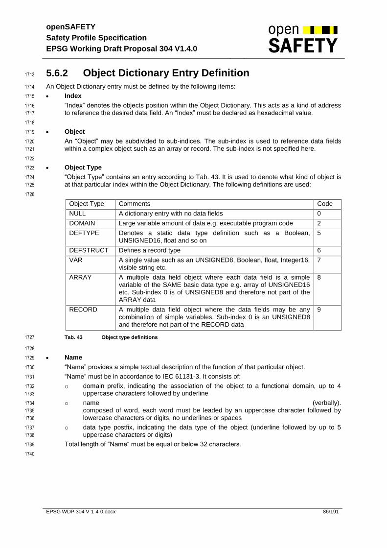
openSAFETY
Safety Profile Specification
EPSG Working Draft Proposal 304 V1.4.0
EPSG WDP 304 V-1-4-0.docx 86/191
5.6.2 Object Dictionary Entry Definition 1713
An Object Dictionary entry must be defined by the following items: 1714
Index 1715
“Index” denotes the objects position within the Object Dictionary. This acts as a kind of address 1716
to reference the desired data field. An “Index” must be declared as hexadecimal value. 1717
1718
Object 1719
An “Object” may be subdivided to sub-indices. The sub-index is used to reference data fields 1720
within a complex object such as an array or record. The sub-index is not specified here. 1721
1722
Object Type 1723
“Object Type” contains an entry according to Tab. 43. It is used to denote what kind of object is 1724
at that particular index within the Object Dictionary. The following definitions are used: 1725
1726
Object Type Comments Code
NULL A dictionary entry with no data fields 0
DOMAIN Large variable amount of data e.g. executable program code 2
DEFTYPE Denotes a static data type definition such as a Boolean, UNSIGNED16, float and so on
5
DEFSTRUCT Defines a record type 6
VAR A single value such as an UNSIGNED8, Boolean, float, Integer16, visible string etc.
7
ARRAY A multiple data field object where each data field is a simple variable of the SAME basic data type e.g. array of UNSIGNED16 etc. Sub-index 0 is of UNSIGNED8 and therefore not part of the ARRAY data
8
RECORD A multiple data field object where the data fields may be any combination of simple variables. Sub-index 0 is an UNSIGNED8 and therefore not part of the RECORD data
9
Tab. 43 Object type definitions 1727
1728
Name 1729
“Name” provides a simple textual description of the function of that particular object. 1730
“Name” must be in accordance to IEC 61131-3. It consists of: 1731
o domain prefix, indicating the association of the object to a functional domain, up to 4 1732
uppercase characters followed by underline 1733
o name (verbally). 1734
composed of word, each word must be leaded by an uppercase character followed by 1735
lowercase characters or digits, no underlines or spaces 1736
o data type postfix, indicating the data type of the object (underline followed by up to 5 1737
uppercase characters or digits) 1738
Total length of “Name“ must be equal or below 32 characters. 1739
1740

openSAFETY
Safety Profile Specification
EPSG Working Draft Proposal 304 V1.4.0
EPSG WDP 304 V-1-4-0.docx 87/191
Data Type 1741
This entry provides information about the data type of the object. These include the following 1742
pre-defined static data types: BOOLEAN, floating point number, UNSIGNED Integer, Signed 1743
Integer, visible/octet string and DOMAIN (see 5.1.1.11). It also includes the pre-defined complex 1744
data types and may also include types which are either manufacturer or device specific. 1745
1746
It is not allowed to define records of records, arrays of records or records with arrays as fields of 1747
that record. In the case where an object is an array or a record, the sub-index is used to 1748
reference one static data type data field within the object. 1749
1750
Category 1751
“Category” defines whether the object is Mandatory (M) or Optional (O). A mandatory object 1752
must be implemented on a device. An optional object does not have to be implemented on a 1753
device. The support of certain objects or features however may require the implementation of 1754
related objects. In this case, the relations are described in the detailed object specification. 1755
1756
“Category” may be Conditional (Cond) if the M/O category of an object depends on the 1757
implementation of another object. 1758
1759
The following entries must be indicated for static data types only. In case of complex data types 1760
the respective entries must be provided for each sub-index individually. 1761
1762
Access 1763
This entry defines the access rights for a particular object. The view point is from the bus into 1764
the device. It can be one of the following: 1765
1766
rw read and write access
wo write only access
ro read only access
Const read only access, value is constant
Tab. 44 Access Attributes for Data Objects 1767
1768
Optional objects listed in the Object Dictionary with the attribute rw may be implemented as 1769
read only. Exceptions are defined in the detailed object specification. 1770
1771
Value Range 1772
This entry indicates the value range of the respective object. It may consist of one or more 1773
distinct values or ranges of values. If the item shown is a data type identifier, the complete value 1774
range of the mentioned data type must be allowed. 1775
1776
Default Value 1777
This entry indicates the initialization value that must be assigned by the profile implementation. 1778
For mappable objects, this value represents also the safe state value. 1779
1780

openSAFETY
Safety Profile Specification
EPSG Working Draft Proposal 304 V1.4.0
EPSG WDP 304 V-1-4-0.docx 88/191
SPDO Mapping 1781
This entry indicates whether an entry may be mapped to an SPDO message. It can be one of 1782
the following: 1783
1784
Opt Object may be mapped into an SPDO
No Object must not be mapped into an SPDO
Tab. 45 SPDO Mapping Attributes for Data Objects 1785
1786
A complete static data type object definition (Object Type = VAR or DOMAIN) example is displayed 1787
below: 1788
1789
Index 1234h Object Type VAR
Name SSDO_VarDummyParameter_S16
Data Type INTEGER16 Category M
Value Range -15 000 .. 10 000 Access rw
Default Value 0 SPDO Mapping
Opt
Tab. 46 Static Data Type Object Definition Example 1790
1791
Complex data type object definitions (Object Type = ARRAY or RECORD) are of reduced form, 1792
because Access, Value Range, Default Value, and SPDO mapping must be defined individually for the 1793
sub-indices 1794
1795
Index 2345h Object Type ARRAY
Name SSDO_ArrayDummyParameter_AU16
Data Type UNSIGNED16 Category M
Tab. 47 Complex Data Type Object Definition Example 1796
1797
“Category” refers to the complex data type object as a whole, but not to the particular sub-1798
index. A mandatory object may be composed of mandatory and optional sub-indices. This 1799
means that the object must be supported but some of its sub-indices are optional. Defining 1800
optional objects with mandatory sub-indices is also permitted. This means that these sub-1801
indices must be supported if the object is implemented. 1802
1803
“Data Type” must contain a static data type for ARRAY type objects and a complex data type 1804
for RECORD type objects. 1805
1806
The definition of data type describing objects (Object Type = DEFTYPE or DEFSTRUCT) is shown in 1807
5.6.3. 1808
1809

openSAFETY
Safety Profile Specification
EPSG Working Draft Proposal 304 V1.4.0
EPSG WDP 304 V-1-4-0.docx 89/191
5.6.2.1 Sub-Index Definition 1810
Complex object types (ARRAY, RECORD objects) are composed of up to 256 data items. Each data 1811
item may be addressed by an UNSIGNED8 type sub-index. 1812
Sub-Indices are used in the following way: 1813
Sub-Index 00h NumberOfEntries 1814
NumberOfEntries describes the highest available sub-index that follows, not considering FFh. 1815
This entry is encoded as UNSIGNED8, regardless the type of the object. If the object exists, 1816
NumberOfEntries is mandatory. Data Type and Category are not denoted in NumberOfEntries 1817
descriptions. 1818
1819
NumberOfEntries is described by this specification as shown below: 1820
Sub-Index 00h
Name NumberOfEntries
Value Range 1..15 Access rw
Default Value 15 SPDO Mapping
No
Tab. 48 NumberOf Entries Sub-Index Description Example 1821
1822
o For ARRAYs, NumberOfEntries may be modified (Access = rw) to show the number of 1823
occupied items in a list. For RECORDs, NumberOfEntries is constant (Access = ro or 1824
Const). 1825
1826
Sub-Index 01h - FEh Object Specific Data 1827
Sub-Indices between 01h and FEh hold the object’s payload data. The highest accessible index 1828
is given by NumberOfEntries. 1829
1830
Sub-Indices of RECORD type objects are defined as follows: 1831
Sub-Index 01h
Name RecItem1_U8
Data Type UNSIGNED8 Category M
Value Range 1..255 Access rw
Default Value 1 SPDO Mapping
Def
Tab. 49 Record Type Object Sub-Index Description Example 1832
1833
o “Name” is composed of a description text followed by a data type postfix. Refer to the 1834
object name rules for further information, the domain prefix is omitted. 1835
If a name entry is defined in a data type definition, the sub-index name is equal to it. 1836
1837
o “Category” refers to the respective sub-index only. Mandatory (M) means that the sub-1838
index must be implemented when the object is implemented. A mandatory sub-index 1839
does not force the hosting object to be mandatory. 1840
1841
1842

openSAFETY
Safety Profile Specification
EPSG Working Draft Proposal 304 V1.4.0
EPSG WDP 304 V-1-4-0.docx 90/191
Sub-Indices of ARRAY type objects are defined as follows: 1843
Sub-Index 01h
Name ArraySubindex1
-- -- Category M
Value Range UNSIGNED16 Access rw
Default Value 0 SPDO Mapping
Opt
Tab. 50 Array Type Object Sub-Index Description Example 1844
1845
o “Name” consists of a description text. Refer to the object name rules for further 1846
information, the domain prefix and data type postfix are omitted. If a name entry is 1847
defined in a data type definition, the sub-index name must be equal to it. 1848
1849
o “Category” refers to the respective sub-index only. Mandatory (M) means that the sub-1850
index must be implemented when the object is implemented. A mandatory sub-index 1851
doesn’t force the hosting object to be mandatory. 1852
1853
o Despite the functional equivalence of all sub-indices in an array, more than one sub-index 1854
entry can be defined to a particular object to show differences of the Category, Access 1855
and / or SPDO Mapping options of the sub-indices. 1856
1857
Sub-Index FFh StructureOfObject 1858
Sub-index FFh describes the structure of the entry by providing the data type and the object type 1859
of the entry. Regardless of the type of the object, it is encoded as UNSIGNED32 and organized 1860
as follows: 1861
1862
MSB LSB
Bit-No. 31 - 24 23 - 16 15 - 8 7 - 0
Value 00h Data Type (refer Tab. 42) Object Type (refer Tab. 43
Tab. 51 Structure of Sub-Index FFh 1863
1864
It is optional to support sub-index FFh. If it is supported throughout the Object Dictionary and the 1865
structure of the complex data types is provided as well, it is possible to upload the entire 1866
structure of the Object Dictionary. If StructureOfEntry is not supported, sub-index FFh is 1867
reserved. 1868
StructureOfObject is not shown by object definitions in this specification. 1869
5.6.3 Data Type Entry Specification 1870
The static data types are placed in the Object Dictionary for definition purposes only. However, indices 1871
in the range 0001h - 0007h may be mapped in order to define the appropriate space of the RxSPDO 1872
(Dummy Mapping) as not being used by the device (do not care). The indices 0009h - 000Bh, 000Fh 1873
may not be mapped to an SPDO. 1874
1875
See Tab. 42, index range 0001h to 04FFh for data type specifying object dictionary entries. 1876
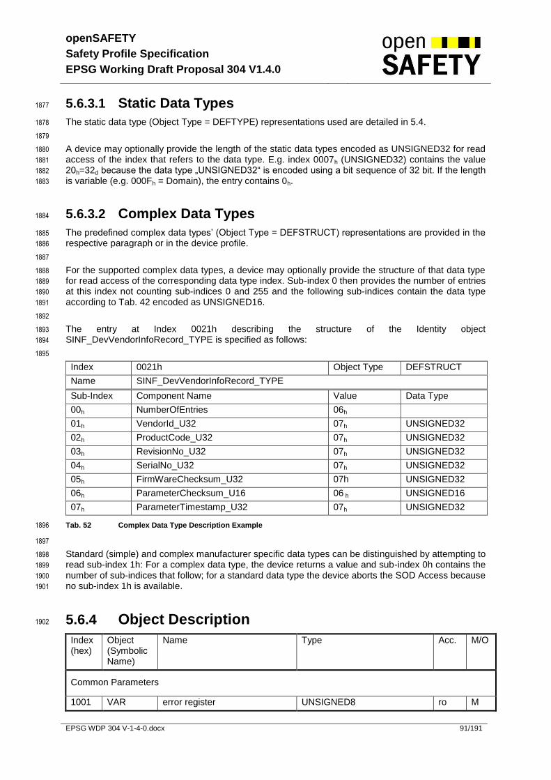
openSAFETY
Safety Profile Specification
EPSG Working Draft Proposal 304 V1.4.0
EPSG WDP 304 V-1-4-0.docx 91/191
5.6.3.1 Static Data Types 1877
The static data type (Object Type = DEFTYPE) representations used are detailed in 5.4. 1878
1879
A device may optionally provide the length of the static data types encoded as UNSIGNED32 for read 1880
access of the index that refers to the data type. E.g. index 0007h (UNSIGNED32) contains the value 1881
20h=32d because the data type „UNSIGNED32“ is encoded using a bit sequence of 32 bit. If the length 1882
is variable (e.g. 000Fh = Domain), the entry contains 0h. 1883
5.6.3.2 Complex Data Types 1884
The predefined complex data types’ (Object Type = DEFSTRUCT) representations are provided in the 1885
respective paragraph or in the device profile. 1886
1887
For the supported complex data types, a device may optionally provide the structure of that data type 1888
for read access of the corresponding data type index. Sub-index 0 then provides the number of entries 1889
at this index not counting sub-indices 0 and 255 and the following sub-indices contain the data type 1890
according to Tab. 42 encoded as UNSIGNED16. 1891
1892
The entry at Index 0021h describing the structure of the Identity object 1893
SINF_DevVendorInfoRecord_TYPE is specified as follows: 1894
1895
Index 0021h Object Type DEFSTRUCT
Name SINF_DevVendorInfoRecord_TYPE
Sub-Index Component Name Value Data Type
00h NumberOfEntries 06h
01h VendorId_U32 07h UNSIGNED32
02h ProductCode_U32 07h UNSIGNED32
03h RevisionNo_U32 07h UNSIGNED32
04h SerialNo_U32 07h UNSIGNED32
05h FirmWareChecksum_U32 07h UNSIGNED32
06h ParameterChecksum_U16 06 h UNSIGNED16
07h ParameterTimestamp_U32 07h UNSIGNED32
Tab. 52 Complex Data Type Description Example 1896
1897
Standard (simple) and complex manufacturer specific data types can be distinguished by attempting to 1898
read sub-index 1h: For a complex data type, the device returns a value and sub-index 0h contains the 1899
number of sub-indices that follow; for a standard data type the device aborts the SOD Access because 1900
no sub-index 1h is available. 1901
5.6.4 Object Description 1902
Index (hex)
Object (Symbolic Name)
Name Type Acc. M/O
Common Parameters
1001 VAR error register UNSIGNED8 ro M

openSAFETY
Safety Profile Specification
EPSG Working Draft Proposal 304 V1.4.0
EPSG WDP 304 V-1-4-0.docx 92/191
1002 VAR manufacturer status register UNSIGNED32 ro O
1003 ARRAY pre-defined error field UNSIGNED32 rw O
:::: :::: :::::::::::::::: :::::::::::: :::: ::::
100C RECORD life guarding SSDO_LifeGuardRecord_TYPE (20h)
rw M
100D VAR Refresh Time for Reset Guarding
UNSIGNED32 rw M
100E VAR Number of Retries for Reset Guarding
UNSIGNED8 rw O
1018 RECORD device vendor information SINF_DevVendorInfoRecord_TYPE (21h)
ro M
1019 VAR unique device id OCTET_STRING ro M
101A DOMAIN parameter download DOMAIN rw O
101B RECORD SCM specific parameters SSCM_SpecificParametersRecord_TYPE (29h)
rw O
Common Communication Parameters
1200 RECORD common communication parameters
SCOM_CommonCommParamRecord_TYPE (22h)
w M
1201 RECORD SSDO communication parameters
SSDO_CommParamRecord_TYPE (23h)
rw C**
1202 RECORD SNMT communication parameters
SNMT_CommParamRecord_TYPE (24h)
Receive SPDO Communication Parameter
1400 RECORD 1st RxSPDO communication parameters
SPDO_RxCommParamRecord_TYPE (25h)
rw
:::: :::: :::::::::::::::: :::::::::::: :::: ::::
17FE RECORD 1023nd RxSPDO communication parameters
SPDO_RxCommParamRecord_TYPE (25h)
rw
Receive SPDO Mapping Parameter
1800 ARRAY 1st RxSPDO mapping parameters
UNSIGNED32 rw O
:::: :::: :::::::::::::::: :::::::::::: :::: ::::
1BFE ARRAY 1023nd RxSPDO mapping parameters
UNSIGNED32 rw O
1903
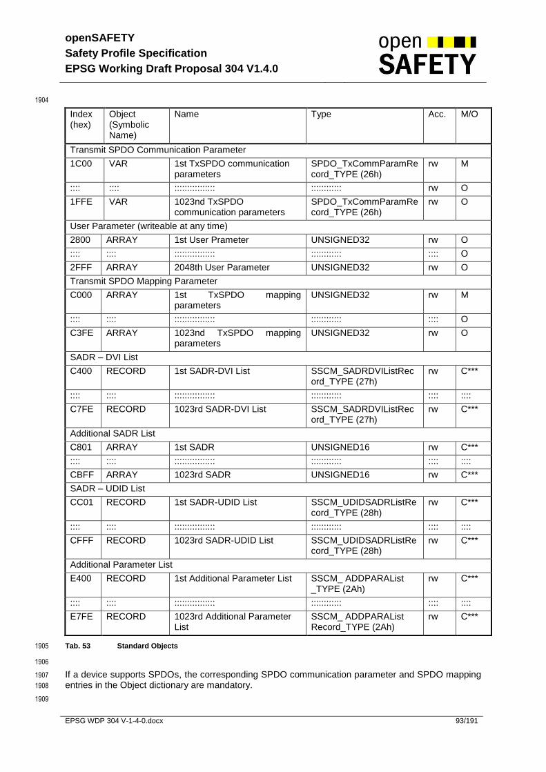
openSAFETY
Safety Profile Specification
EPSG Working Draft Proposal 304 V1.4.0
EPSG WDP 304 V-1-4-0.docx 93/191
1904
Index (hex)
Object (Symbolic Name)
Name Type Acc. M/O
Transmit SPDO Communication Parameter
1C00 VAR 1st TxSPDO communication parameters
SPDO_TxCommParamRecord_TYPE (26h)
rw M
:::: :::: :::::::::::::::: :::::::::::: rw O
1FFE VAR 1023nd TxSPDO communication parameters
SPDO_TxCommParamRecord_TYPE (26h)
rw O
User Parameter (writeable at any time)
2800 ARRAY 1st User Prameter UNSIGNED32 rw O
:::: :::: :::::::::::::::: :::::::::::: :::: O
2FFF ARRAY 2048th User Parameter UNSIGNED32 rw O
Transmit SPDO Mapping Parameter
C000 ARRAY 1st TxSPDO mapping parameters
UNSIGNED32 rw M
:::: :::: :::::::::::::::: :::::::::::: :::: O
C3FE ARRAY 1023nd TxSPDO mapping parameters
UNSIGNED32 rw O
SADR – DVI List
C400 RECORD 1st SADR-DVI List SSCM_SADRDVIListRecord_TYPE (27h)
rw C***
:::: :::: :::::::::::::::: :::::::::::: :::: ::::
C7FE RECORD 1023rd SADR-DVI List SSCM_SADRDVIListRecord_TYPE (27h)
rw C***
Additional SADR List
C801 ARRAY 1st SADR UNSIGNED16 rw C***
:::: :::: :::::::::::::::: :::::::::::: :::: ::::
CBFF ARRAY 1023rd SADR UNSIGNED16 rw C***
SADR – UDID List
CC01 RECORD 1st SADR-UDID List SSCM_UDIDSADRListRecord_TYPE (28h)
rw C***
:::: :::: :::::::::::::::: :::::::::::: :::: ::::
CFFF RECORD 1023rd SADR-UDID List SSCM_UDIDSADRListRecord_TYPE (28h)
rw C***
Additional Parameter List
E400 RECORD 1st Additional Parameter List SSCM_ ADDPARAList _TYPE (2Ah)
rw C***
:::: :::: :::::::::::::::: :::::::::::: :::: ::::
E7FE RECORD 1023rd Additional Parameter List
SSCM_ ADDPARAList Record_TYPE (2Ah)
rw C***
Tab. 53 Standard Objects 1905
1906
If a device supports SPDOs, the corresponding SPDO communication parameter and SPDO mapping 1907
entries in the Object dictionary are mandatory. 1908
1909

openSAFETY
Safety Profile Specification
EPSG Working Draft Proposal 304 V1.4.0
EPSG WDP 304 V-1-4-0.docx 94/191
** The parameters only have to be available if the node can be an SSDO client. 1910
*** Only needs to be implemented if the device has SCM functionality 1911
1912
This chapter describes the standard object dictionary entries for a SN and SCM. The implementation 1913
of these objects may differ from the description within the specification. For example the “Main SADR” 1914
might be a read only parameter in case it is to be set using a dip switch. 1915
1916

openSAFETY
Safety Profile Specification
EPSG Working Draft Proposal 304 V1.4.0
EPSG WDP 304 V-1-4-0.docx 95/191
5.6.4.1 Object 1001h: Error Register 1917
This object is an error register for the device. The device can map internal errors in this byte. If the 1918
value of the object is zero, the device is ok. All other values signal that the device is in an error state. 1919
The error codes for the error descriptions are described in Tab. 54. 1920
1921
Index 1001h
Name SERR_GeneralError_U8
Data Type UNSIGNED8 Category M
Value Range UNSIGNED8 Access ro
Default Value 0 SPDO Mapping Yes
Relevant for SOD checksum No
1922
Value interpretation 1923
Bit M/O Description
0 M generic error
1 O current
2 O voltage
3 O temperature
4 O communication error (overrun, error state)
5 O device profile specific
6 O Reserved (always 0)
7 O manufacturer specific
Tab. 54 Structure of the Error Register 1924
5.6.4.2 Object 1002h: Manufacturer status register 1925
This object is a status register for manufacturer purposes. In this document, only the size and location 1926
of this object is defined. 1927
Index 1002h
Name SERR_ManufacturerStatus_U32
Data Type UNSIGNED32 Category O
Value Range UNSIGNED32 Access ro
Default Value 0 SPDO Mapping Yes
Relevant for SOD checksum No
1928
1929
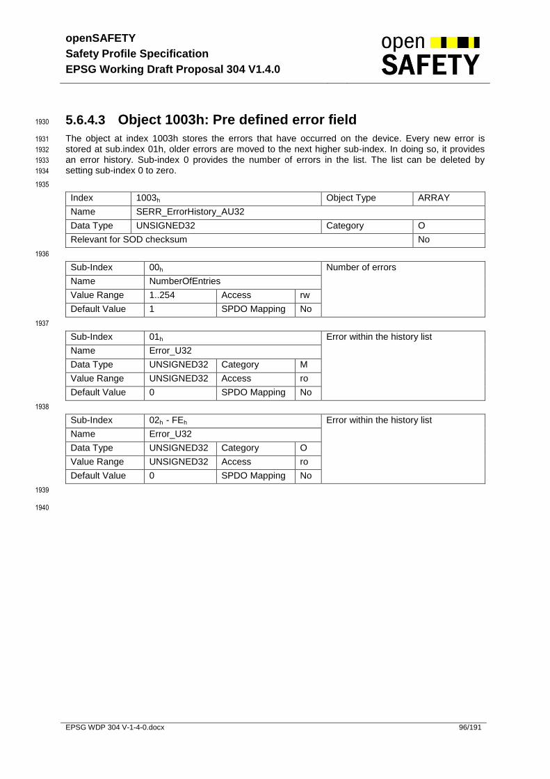
openSAFETY
Safety Profile Specification
EPSG Working Draft Proposal 304 V1.4.0
EPSG WDP 304 V-1-4-0.docx 96/191
5.6.4.3 Object 1003h: Pre defined error field 1930
The object at index 1003h stores the errors that have occurred on the device. Every new error is 1931
stored at sub.index 01h, older errors are moved to the next higher sub-index. In doing so, it provides 1932
an error history. Sub-index 0 provides the number of errors in the list. The list can be deleted by 1933
setting sub-index 0 to zero. 1934
1935
Index 1003h Object Type ARRAY
Name SERR_ErrorHistory_AU32
Data Type UNSIGNED32 Category O
Relevant for SOD checksum No
1936
Sub-Index 00h Number of errors
Name NumberOfEntries
Value Range 1..254 Access rw
Default Value 1 SPDO Mapping No
1937
Sub-Index 01h Error within the history list
Name Error_U32
Data Type UNSIGNED32 Category M
Value Range UNSIGNED32 Access ro
Default Value 0 SPDO Mapping No
1938
Sub-Index 02h - FEh Error within the history list
Name Error_U32
Data Type UNSIGNED32 Category O
Value Range UNSIGNED32 Access ro
Default Value 0 SPDO Mapping No
1939
1940

openSAFETY
Safety Profile Specification
EPSG Working Draft Proposal 304 V1.4.0
EPSG WDP 304 V-1-4-0.docx 97/191
5.6.4.4 Object 1004h: Error statistics 1941
openSAFETY frames can be invalid or denied for various reasons. To ease the integration as well as 1942
testing of an openSAFETY stack implementation, various error counters can be used to determine, 1943
how an openSAFETY stack implementation has treated incoming packages. These objects are 1944
mandatory. Additionally 4 error counters are only implemented, if the corresponding openSAFETY 1945
stack implementation uses the appropriate modules. 1946
1947
Index 1004h Object Type ARRAY
Name SERR_ErrorStatistics_AU32
Data Type UNSIGNED32 Category O
Relevant for SOD checksum No
1948
Sub-Index 00h Number of error statistic entries
Name NumberOfEntries
Value Range 0Eh Access rw
Default Value 0Eh SPDO Mapping No
1949
Sub-Index 01h Defined payload length for the frame differs from the received data Name SFS_LENGTH
Value Range UNSIGNED32 Access ro
Default Value 0 SPDO Mapping No
1950
Sub-Index 02h Safety frame is too long
Name SFS_TOO_LONG
Value Range UNSIGNED32 Access ro
Default Value 0 SPDO Mapping No
1951
Sub-Index 03h Frame IDs differ between sub-frame 1 and 2 Name SFS_FRAME_ID
Value Range UNSIGNED32 Access ro
Default Value 0 SPDO Mapping No
1952
Sub-Index 04h Invalid SADR provided
Name SFS_SADR_INVALID
Value Range UNSIGNED32 Access ro
Default Value 0 SPDO Mapping No
1953
Sub-Index 05h Invalid SDN provided
Name SFS_SDN_INVALID
Value Range UNSIGNED32 Access ro
Default Value 0 SPDO Mapping No
1954
Sub-Index 06h Invalid TADR provided

openSAFETY
Safety Profile Specification
EPSG Working Draft Proposal 304 V1.4.0
EPSG WDP 304 V-1-4-0.docx 98/191
Name SFS_TADR_INVALID
Value Range UNSIGNED32 Access ro
Default Value 0 SPDO Mapping No
1955
Sub-Index 07h CRC for subframe 1 is invalid
Name SFS_CRC1_INVALID
Value Range UNSIGNED32 Access ro
Default Value 0 SPDO Mapping No
1956
Sub-Index 08h CRC for subframe 2 is invalid
Name SFS_CRC2_INVALID
Value Range UNSIGNED32 Access ro
Default Value 0 SPDO Mapping No
1957
Sub-Index 09h Payload differs between sub-frame 1 and 2 Name SFS_DATA
Value Range UNSIGNED32 Access ro
Default Value 0 SPDO Mapping No
1958
Sub-Index 0Ah Cyclic frame rejected because not applicable for SN Name CYC_REJECT
Value Range UNSIGNED32 Access ro
Default Value 0 SPDO Mapping No
1959
Sub-Index 0Bh Generic cyclic frame error, frame was intended for SN Name CYC_ERROR
Value Range UNSIGNED32 Access ro
Default Value 0 SPDO Mapping No
1960
Sub-Index 0Ch SNMT/SSDO frame rejected because not applicable for SN Name ACYC_REJECT
Value Range UNSIGNED32 Access ro
Default Value 0 SPDO Mapping No
1961
Sub-Index 0Dh SNMT/SSDO retry
Name ACYC_RETRY
Value Range UNSIGNED32 Access ro
Default Value 0 SPDO Mapping No
1962
Sub-Index 0Eh Common error counter
Name COMMON_CTR
Value Range UNSIGNED32 Access ro
Default Value 0 SPDO Mapping No

openSAFETY
Safety Profile Specification
EPSG Working Draft Proposal 304 V1.4.0
EPSG WDP 304 V-1-4-0.docx 99/191
5.6.4.5 Object 100Ch: Life Guarding 1963
This object defines the Life Guarding Protocol. The guard time is the time interval in which the SN 1964
should receive a life time signal from the SCM. The life time factor multiplied by the guard time results 1965
in the life time of the node. The time interval for sending the life time signal to the SNs is calculated by 1966
dividing the GuardTime_U32 by the number of nodes. The guard time interval for a SN within the SCM 1967
is started after receiving the last guarding response from the SN. 1968
Index 100C h Object Type RECORD
Name SSDO_LifeGuard_REC
Data Type SSDO_LifeGuardRecord_TYPE Category M
Relevant for SOD checksum Yes
1969
Sub-Index 00h Number of Entries within this index.
Name NumberOfEntries
Value Range 2 Access ro
Default Value 2 SPDO Mapping No
1970
Sub-Index 01h Guard time for the lifetime protocol. The time base of this parameter is defined by CommonCommParam_REC. ConsecutiveTimeBase_I8.
The values range may be limited vendor specific due to implementation reasons to a smaller value than 2
32
Name GuardTime_U32
Data Type UNSIGNED32 Category M
Value Range UNSIGNED32 Access rw
Default Value 10000000 SPDO Mapping No
1971
Sub-Index 02h Number of times how often the GuardTime_U32 may elapse before the node switches back from Operational to Pre-Operational
Name LifeTimeFactor_U8
Data Type UNSIGNED8 Category M
Value Range 1 .. 255 Access rw
Default Value 2 SPDO Mapping No
1972
5.6.4.6 Object 100Dh: Number of Retries for Reset Guarding 1973
This object contains the refresh interval of the Reset Guarding (see chapter 5.7.6.2). This defines the 1974
time delay between each individual SNMT_SN_reset_guarding_SCM signal sent by the SN to it’s 1975
accompanying SCM during operational and boot-up phases. The number of attempts during boot-up 1976
can be defined by 0x100E (see chapter 5.6.4.7). 1977
1978
Index 100Dh The sub-index provides the refresh time for the SNMT_SN_reset_guarding_SCM service. The time base of this parameter is defined by CommonCommParam_REC.ConsecutiveTimeBase_I8.
Name SNMT_ResetGuarding_U32
Data Type UNSIGNED32 Category M
Value Range UNSIGNED32 Access rw
Default Value 100000 SPDO Mapping No
Relevant for SOD checksum No
1979

openSAFETY
Safety Profile Specification
EPSG Working Draft Proposal 304 V1.4.0
EPSG WDP 304 V-1-4-0.docx 100/191
5.6.4.7 Object 100Eh: Refresh interval of Reset Guarding 1980
This object contains number of retries a SN performs to contact its accompanying SCM using Reset 1981
Guarding (see chapter 5.7.6.2) during boot-up of the SN. The time interval between each message is 1982
defined by 0x100D (see chapter 5.6.4.8). The parameter is optional and if omitted an infinite number 1983
of tries is assumed. 1984
1985
Index 100Eh This parameter is optional and sets the maximum number of Reset Guarding telegrams sent at boot-up. If the value is set to 255 the Reset Guarding telegram is infinitely repeated. If the value is set to 0 – 254 the Reset Guarding telegram is not sent anymore after the set number of repetitions.
Name SNMT_NoResetGuarding_U8
Data Type UNSIGNED8 Category O
Value Range UNSIGNED8 Access rw
Default Value Manufacturer specific
SPDO Mapping No
Relevant for SOD checksum No
1986
5.6.4.8 Object 1018h: Device Vendor Information 1987
This object contains the vendor specific device information. It also defines compatible devices. Any 1988
device with an identical Vendor-ID, Product code, Major Revision Number and a Minor Revision 1989
Number greater or equal to another device must be compatible. The manufacturer of a device has to 1990
verify and ensure the compatibility for minor revision changes on a safety related device. 1991
1992
Index 1018h Object Type RECORD
Name SINF_DevVendorInfo_REC
Data Type SINF_DevVendorInfoRecord_TYPE Category M
Relevant for SOD checksum No
1993
Sub-Index 00h Number of Entries within this index.
Name NumberOfEntries
Value Range 9 Access ro
Default Value 9 SPDO Mapping No
1994
Sub-Index 01h Vendor ID according EPSG Vendor List Name VendorID_32
Data Type UNSIGNED32 Category M
Value Range UNSIGNED32 Access ro
Default Value 0 SPDO Mapping No
1995
Sub-Index 02h The manufacturer-specific product code identifies a specific device version
Name ProductCode_U32
Data Type UNSIGNED32 Category M
Value Range UNSIGNED32 Access ro
Default Value 0 SPDO Mapping No
1996

openSAFETY
Safety Profile Specification
EPSG Working Draft Proposal 304 V1.4.0
EPSG WDP 304 V-1-4-0.docx 101/191
Sub-Index 03h See specification below
Name RevisionNumber_U32
Data Type UNSIGNED32 Category M
Value Range UNSIGNED32 Access ro
Default Value 0 SPDO Mapping No
1997
Sub-Index 04h Serial Number of the device
Name SerialNumber_U32
Data Type UNSIGNED32 Category M
Value Range UNSIGNED32 Access ro
Default Value 0 SPDO Mapping No
1998
Sub-Index 05h Vendor specific FW Checksum
Name FirmWareChecksum_U32
Data Type UNSIGNED32 Category M
Value Range UNSIGNED32 Access ro
Default Value 0 SPDO Mapping No
1999
Sub-Index 06h Contains the SOD parameter checksum container (to be calculated as described below).
Timestamp
CRC32
CRC32
…
Name ParameterChecksum_DOM
Data Type DOMAIN Category M
Value Range DOMAIN Access rw
Default Value 0 SPDO Mapping No
2000
Sub-Index 07h Parameter Timestamp, to be the same as in the ParameterChecksum object. The parameter timestamp is created by the configuration tool and is verified in each module at start-up by the SCM (see chapter 5.7.13). Timestamp format is seconds since 1.1.1970 (UNIX timestamp).
Name ParameterTimestamp_U32
Data Type UNSIGNED32 Category M
Value Range UNSIGNED32 Access ro
Default Value 0 SPDO Mapping No
2001
Sub-Index 08h Checksum, which defines the openSAFETY stack implementation used for creating the device firmware
Name openSAFETY_Stack_ChkSum_U32
Data Type UNSIGNED32 Category M
Value Range UNSIGNED32 Access ro
Default Value 0 SPDO Mapping No
2002
Sub-Index 09h Stores the version of the openSAFETY protocol implementation, using the method described below
Name openSAFETY_Stack_Version_U16
Data Type UNSIGNED16 Category M
Value Range UNSIGNED16 Access ro
Default Value 0 SPDO Mapping No
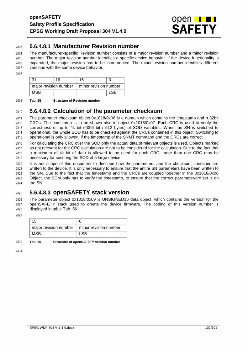
openSAFETY
Safety Profile Specification
EPSG Working Draft Proposal 304 V1.4.0
EPSG WDP 304 V-1-4-0.docx 102/191
5.6.4.8.1 Manufacturer Revision number 2003
The manufacturer-specific Revision number consists of a major revision number and a minor revision 2004
number. The major revision number identifies a specific device behavior. If the device functionality is 2005
expanded, the major revision has to be incremented. The minor revision number identifies different 2006
versions with the same device behavior. 2007
2008
31 16 15 0
major revision number minor revision number
MSB LSB
Tab. 55 Structure of Revision number 2009
5.6.4.8.2 Calculation of the parameter checksum 2010
The parameter checksum object 0x1018/0x06 is a domain which contains the timestamp and n 32bit 2011
CRCs. The timestamp is to be shown also in object 0x1018/0x07. Each CRC is used to verify the 2012
correctness of up to 4k bit (4096 bit / 512 bytes) of SOD variables. When the SN is switched to 2013
operational, the whole SOD has to be checked against the CRCs contained in this object. Switching to 2014
operational is only allowed, if the timestamp of the SNMT command and the CRCs are correct. 2015
For calculating the CRC over the SOD only the actual data of relevant objects is used. Objects marked 2016
as not relevant for the CRC calculation are not to be considered for the calculation. Due to the fact that 2017
a maximum of 4k bit of data is allowed to be used for each CRC, more than one CRC may be 2018
necessary for securing the SOD of a large device. 2019
It is not scope of this document to describe how the parameters and the checksum container are 2020
written to the device. It is only necessary to ensure that the entire SN parameters have been written to 2021
the SN. Due to the fact that the timestamp and the CRCs are coupled together in the 0x1018/0x06 2022
Object, the SCM only has to verify the timestamp, to ensure that the correct parameter/crc set is on 2023
the SN. 2024
5.6.4.8.3 openSAFETY stack version 2025
The parameter object 0x1018/0x09 is UNSIGNED16 data object, which contains the version for the 2026
openSAFETY stack used to create the device firmware. The coding of this version number is 2027
displayed in table Tab. 56 2028
2029
15 0
major revision number minor revision number
MSB LSB
Tab. 56 Structure of openSAFETY version number 2030
2031
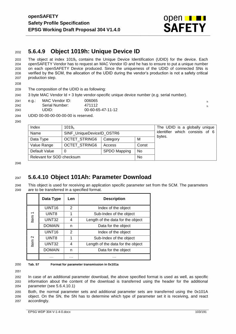
openSAFETY
Safety Profile Specification
EPSG Working Draft Proposal 304 V1.4.0
EPSG WDP 304 V-1-4-0.docx 103/191
5.6.4.9 Object 1019h: Unique Device ID 2032
The object at index 1019h contains the Unique Device Identification (UDID) for the device. Each 2033
openSAFETY Vendor has to request an MAC Vendor ID and he has to ensure to put a unique number 2034
on each openSAFETY Device produced. Since the uniqueness of the UDID of connected SNs is 2035
verified by the SCM, the allocation of the UDID during the vendor’s production is not a safety critical 2036
production step. 2037
2038
The composition of the UDID is as following: 2039
3 byte MAC Vendor Id + 3 byte vendor-specific unique device number (e.g. serial number). 2040
e.g.: MAC Vendor ID: 006065 h 2041
Serial Number: 471112 h 2042
UDID: 00-60-65-47-11-12 2043
UDID 00-00-00-00-00-00 is reserved. 2044
2045
Index 1019h The UDID is a globally unique identifier which consists of 6 bytes.
Name SINF_UniqueDeviceID_OSTR6
Data Type OCTET_STRING6 Category M
Value Range OCTET_STRING6 Access Const
Default Value 0 SPDO Mapping No
Relevant for SOD checksum No
2046
5.6.4.10 Object 101Ah: Parameter Download 2047
This object is used for receiving an application specific parameter set from the SCM. The parameters 2048
are to be transferred in a specified format. 2049
Data Type Len Description
Item
1
UINT16 2 Index of the object
UINT8 1 Sub-Index of the object
UINT32 4 Length of the data for the object
DOMAIN n Data for the object
Item
2
UINT16 2 Index of the object
UINT8 1 Sub-Index of the object
UINT32 4 Length of the data for the object
DOMAIN n Data for the object
… … …
Tab. 57 Format for parameter transmission in 0x101a 2050
2051
In case of an additional parameter download, the above specified format is used as well, as specific 2052
information about the content of the download is transferred using the header for the additional 2053
parameter (see 5.6.4.10.1) 2054
Both, the normal parameter sets and additional parameter sets are transferred using the 0x101A 2055
object. On the SN, the SN has to determine which type of parameter set it is receiving, and react 2056
accordingly. 2057

openSAFETY
Safety Profile Specification
EPSG Working Draft Proposal 304 V1.4.0
EPSG WDP 304 V-1-4-0.docx 104/191
Index 101Ah
Name SSDO_ParameterDownload_DOM
Data Type DOMAIN Category O
Value Range DOMAIN Access rw
Default Value 0 SPDO Mapping No
Relevant for SOD checksum No
2058
5.6.4.10.1 Additional Parameter Header 2059
2060
Additional parameter download uses a header to provide information about the parameter set. The 2061
following format is used for this header: 2062
2063
Data Type Len Name
UINT8 1 Parameter Set number
UINT8 1 Header Version (reserved for future use)
UINT16 2 SAddr of SN
UINT32 4 Octet size for parameter set without header
UINT32 4 CRC for parameter set without header
UINT32 4 Timestamp for parameter set
Tab. 58 Format for additional parameter header 2064
5.6.4.11 Object 101Bh: SCM Parameters 2065
The object at index 101Bh contains the SCM specific parameters. 2066
Index 101Bh Object Type RECORD
Name SSCM_SpecificParameters_REC
Data Type SSCM_SpecificParametersRecord_TYPE Category O
Relevant for SOD checksum No
2067
Sub-Index 00h Number of Entries within this index.
Name NumberOfEntries
Value Range 1 Access ro
Default Value 1 SPDO Mapping No
2068
Sub-Index 01h SCM configuration mode according to chapter 3.1.2.
0 … ACM
1 … MCM
Name ConfigurationMode_U8
Data Type UNSIGNED8 Category M
Value Range 0-1 Access rw
Default Value 0 SPDO Mapping No
2069
2070

openSAFETY
Safety Profile Specification
EPSG Working Draft Proposal 304 V1.4.0
EPSG WDP 304 V-1-4-0.docx 105/191
5.6.4.12 Object 1200h: Common Communication Parameter 2071
This object contains the common communication parameters for the device. Sub-index 3 contains the 2072
consecutive time base for the module. It is not necessary for a device to support all possible time 2073
bases. The minimum requirement is to support a time base of 100μs (type 2). 2074
2075
Index 1200h Object Type RECORD
Name SCOM_CommonCommParam_REC
Data Type SCOM_CommonCommParamRecord_TYPE
Category M
Relevant for SOD checksum Yes
2076
Sub-Index 00h Number of Entries within this index.
Name NumberOfEntries
Value Range 4 Access ro
Default Value 4 SPDO Mapping No
2077
Sub-Index 01h openSAFETY Domain Number of the device Name SDN_U16
Data Type UNSIGNED16 Category M
Value Range 0 - 1023 Access ro
Default Value 0 SPDO Mapping No
2078
Sub-Index 02h openSAFETY Address of the SCM within the SD. Name SADR_U16
Data Type UNSIGNED16 Category M
Value Range 0 - 1023 Access ro
Default Value 0 SPDO Mapping No
2079
Sub-Index 03h time base for the CT field: 1 μs x 10
ConsecutiveTimeBase_I8
0 1 μs 1 10 μs 2 100 μs 3 1000 μs
Name ConsecutiveTimeBase_I8
Data Type INTEGER8 Category M
Value Range 0 - 3 Access rw
Default Value 2 SPDO Mapping No
2080
Sub-Index 04h UDID of the SCM
Name UDIDofSCM_ OSTR6
Data Type OCTET_STRING6 Category M
Value Range OCTET_STRING6 Access rw
Default Value UDID of the own SN
SPDO Mapping
No
2081
2082

openSAFETY
Safety Profile Specification
EPSG Working Draft Proposal 304 V1.4.0
EPSG WDP 304 V-1-4-0.docx 106/191
5.6.4.13 Object 1201h: SSDO Communication Parameter 2083
This object defines the SSDO communication parameters of an SSDO client. 2084
2085
Index 1201h Object Type RECORD
Name SSDO_CommParam_REC
Data Type SSDO_CommParamRecord_TYPE Category C
Relevant for SOD checksum No
2086
Sub-Index 00h Number of Entries within this index.
Name NumberOfEntries
Value Range 2 Access ro
Default Value 2 SPDO Mapping No
2087
Sub-Index 01h The sub-index provides the timeout for an SSDO telegram. The time base of this parameter is defined by CommonCommParam_REC.ConsecutiveTimeBase_I8.
Name Timeout_U32
Data Type UNSIGNED32 Category M
Value Range 1-UNSIGNED32
Access rw
Default Value 500000 SPDO Mapping No
2088
Sub-Index 02h This sub-index provides the number of retries for an SSDO telegram. Name Retries_U8
Data Type UNSIGNED8 Category M
Value Range 0-255 Access rw
Default Value 0 SPDO Mapping No
2089
2090

openSAFETY
Safety Profile Specification
EPSG Working Draft Proposal 304 V1.4.0
EPSG WDP 304 V-1-4-0.docx 107/191
5.6.4.14 Object 1202h: SNMT Communication Parameter 2091
This object defines the SNMT communication parameters of an SNMT master. 2092
2093
Index 1202h Object Type RECORD
Name SNMT_CommParam_REC
Data Type SNMT_CommParamRecord_TYPE Category C
Relevant for SOD checksum No
2094
Sub-Index 00h Number of Entries within this index.
Name NumberOfEntries
Value Range 2 Access ro
Default Value 2 SPDO Mapping No
2095
Sub-Index 01h The sub-index provides the timeout for an SNMT telegram. The time base of this parameter is defined by CommonCommParam_REC.ConsecutiveTimeBase_I8.
Name Timeout_U32
Data Type UNSIGNED32 Category M
Value Range 1-UNSIGNED32
Access rw
Default Value 500000 SPDO Mapping No
2096
Sub-Index 02h This sub-index provides the number of retries for an SNMT telegram. Name Retries_U8
Data Type UNSIGNED8 Category M
Value Range 0-255 Access rw
Default Value 0 SPDO Mapping No
2097
2098

openSAFETY
Safety Profile Specification
EPSG Working Draft Proposal 304 V1.4.0
EPSG WDP 304 V-1-4-0.docx 108/191
5.6.4.15 Object 1400h –17FEh: RxSPDO Communication Par. 2099
This object defines from which SADR data is received. 2100
Attention: One producer can have more SADRs (one for each TxSPDO). Therefore one consumer 2101
can have more than one RxSPDO for the same physical producer. 2102
2103
Index 1400h – 17FEh Object Type RECORD
Name SPDO_RxCommParam_XXXh_REC
Data Type SPDO_RxCommParamRecord_TYPE Category O
Relevant for SOD checksum Yes
2104
Sub-Index 00h Number of Entries within this index.
Name NumberOfEntries
Value Range 0Ch Access ro
Default Value 0Ch SPDO Mapping No
2105
Sub-Index 01h Defines the SADR from which the RxSPDO data is to be received. Setting the SADR to zero, deactivates the SPDO.
Name SADR_U16
Data Type UNSIGNED16 Category M
Value Range 0-1023 Access rw
Default Value 0 SPDO Mapping No
2106
Sub-Index 02h Defines the SCT timer for the data from this RxSPDO (see chapter 5.7.1.2). The time base of this parameter is defined by CommonCommParam_REC.ConsecutiveTimeBase_I8.
Name SCT_U32
Data Type UNSIGNED32 Category M
Value Range 1-UNSIGNED32
Access rw
Default Value 1 SPDO Mapping No
2107
Sub-Index 03h The sub-index provides the number of consecutive time requests. Name NumberOfConsecutiveTReq_U8
Data Type UNSIGNED8 Category M
Value Range 1-63 Access rw
Default Value 1 SPDO Mapping No
2108
Sub-Index 04h This sub-index provides the time delay between two sets of consecutive time requests. The time base of this parameter is defined by CommonCommParam_REC.ConsecutiveTimeBase_I8.
Name TimeDelayTReq_U32
Data Type UNSIGNED32 Category M
Value Range UNSIGNED32 Access rw
Default Value 0 SPDO Mapping No
2109
Sub-Index 05h This sub-index provides the time delay between successful time synchronization and the next time
Name TimeDelaySync_U32
Data Type UNSIGNED32 Category M
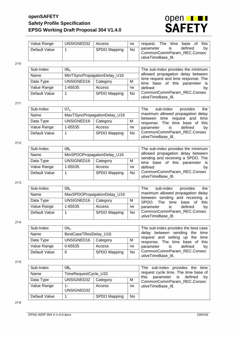
openSAFETY
Safety Profile Specification
EPSG Working Draft Proposal 304 V1.4.0
EPSG WDP 304 V-1-4-0.docx 109/191
Value Range UNSIGNED32 Access rw request. The time base of this parameter is defined by CommonCommParam_REC.ConsecutiveTimeBase_I8.
Default Value 1 SPDO Mapping No
2110
Sub-Index 06h The sub-index provides the minimum allowed propagation delay between time request and time response. The time base of this parameter is defined by CommonCommParam_REC.ConsecutiveTimeBase_I8.
Name MinTSyncPropagationDelay_U16
Data Type UNSIGNED16 Category M
Value Range 1-65535 Access rw
Default Value 1 SPDO Mapping No
2111
Sub-Index 07h The sub-index provides the maximum allowed propagation delay between time request and time response. The time base of this parameter is defined by CommonCommParam_REC.ConsecutiveTimeBase_I8.
Name MaxTSyncPropagationDelay_U16
Data Type UNSIGNED16 Category M
Value Range 1-65535 Access rw
Default Value 1 SPDO Mapping No
2112
Sub-Index 08h The sub-index provides the minimum allowed propagation delay between sending and receiving a SPDO. The time base of this parameter is defined by CommonCommParam_REC.ConsecutiveTimeBase_I8.
Name MinSPDOPropagationDelay_U16
Data Type UNSIGNED16 Category M
Value Range 1-65535 Access rw
Default Value 1 SPDO Mapping No
2113
Sub-Index 09h The sub-index provides the maximum allowed propagation delay between sending and receiving a SPDO. The time base of this parameter is defined by CommonCommParam_REC.ConsecutiveTimeBase_I8.
Name MaxSPDOPropagationDelay_U16
Data Type UNSIGNED16 Category M
Value Range 1-65535 Access rw
Default Value 1 SPDO Mapping No
2114
Sub-Index 0Ah The sub-index provides the best case delay between sending the time request and setting up the time response. The time base of this parameter is defined by CommonCommParam_REC.ConsecutiveTimeBase_I8.
Name BestCaseTResDelay_U16
Data Type UNSIGNED16 Category M
Value Range 0-65535 Access rw
Default Value 0 SPDO Mapping No
2115
Sub-Index 0Bh The sub-index provides the time request cycle time. The time base of this parameter is defined by CommonCommParam_REC.ConsecutiveTimeBase_I8.
Name TimeRequestCycle_U32
Data Type UNSIGNED32 Category M
Value Range 1-UNSIGNED32
Access rw
Default Value 1 SPDO Mapping No
2116

openSAFETY
Safety Profile Specification
EPSG Working Draft Proposal 304 V1.4.0
EPSG WDP 304 V-1-4-0.docx 110/191
Sub-Index 0Ch Contains the TxSPDO number with which the time request is to be sent. Name TxSPDONo_U16
Data Type UNSIGNED16 Category M
Value Range 1-1023 Access rw
Default Value 1 SPDO Mapping No
5.6.4.16 Object 1800h – 1BFEh: RxSPDO Mapping Parameter 2117
This object defines the RxSPDO mapping parameters. The mapping parameters may be pre-defined 2118
by the vendor and read only. For a detailed description of the SPDO mapping, refer to 5.6.5. 2119
2120
Index 1800h – 1BFEh Object Type ARRAY
Name SPDO_RxMappParam_XXXh_AU32
Data Type UNSIGNED32 Category O
Relevant for SOD checksum Yes
2121
Sub-Index 00h Number of Entries within this index.
Name NumberOfEntries
Value Range 0-254 Access rw / ro
Default Value 0 SPDO Mapping No
2122
Sub-Index 01h The sub-index provides the mapping parameter for this RxSPDO Name SPDOMapping_U32
Data Type UNSIGNED32 Category M
Value Range UNSIGNED32
Access rw / ro
Default Value 0 SPDO Mapping No
2123
Sub-Index 02h - FEh The sub-index provides the mapping parameter for this RxSPDO Name SPDOMapping_U32
Data Type UNSIGNED32 Category O
Value Range UNSIGNED32
Access rw / ro
Default Value 0 SPDO Mapping No
2124
2125

openSAFETY
Safety Profile Specification
EPSG Working Draft Proposal 304 V1.4.0
EPSG WDP 304 V-1-4-0.docx 111/191
5.6.4.17 Object 1C00h – 1FFEh: TxSPDO Communication Par. 2126
Each SN must have at least one TxSPDO, either for sending data (producer) or for the time request 2127
(consumer). 2128
2129
Index 1C00h – 1FFEh Object Type RECORD
Name SPDO_TxCommParam_XXXh_REC
Data Type SPDO_TxCommParamRecord_TYPE Category M/O
Relevant for SOD checksum Yes
2130
Sub-Index 00h Number of Entries within this index.
Name NumberOfEntries
Value Range 3 Access ro
Default Value 3 SPDO Mapping No
2131
Sub-Index 01h Defines the SADR that is used when broadcasting the data of the corresponding TxSPDO within the network. Setting the SADR to zero, deactivates the SPDO.
Name SADR_XXXh_U16
Data Type UNSIGNED16 Category M
Value Range 0-1023 Access rw
Default Value 0 SPDO Mapping No
2132
Sub-Index 02h The sub-index provides the refresh time of the Producer. The time base of this parameter is defined by CommonCommParam_REC.ConsecutiveTimeBase_I8.
Name RefreshPrescale_U16
Data Type UNSIGNED16 Category M
Value Range 1 - 32767 Access rw
Default Value 1 SPDO Mapping No
2133
Sub-Index 03h Defines the number of consecutive TRes for a received TReq. If the parameter is zero the TxSPDO can only be used for TReq telegrams (for devices which are consumers only).
Name NumberOfTRes_U8
Data Type UNSIGNED8 Category MC
Value Range UNSIGNED8 Access rw
Default Value 0 SPDO Mapping No
2134
5.6.4.18 Object 2800h – 2FFFh: User Par. (writeable at any time) 2135
These objects defines user parameters which can be written at any time. These parameters may not 2136
be part of the SOD CRC and access to these parameters using SLIM SSDO Services is prohibited. 2137
2138
The structure of these objects is vendor specific. 2139
5.6.4.19 Object C000h – C3FEh: TxSPDO Mapping Parameter 2140
This object defines the TxSPDO mapping parameters. The mapping parameters may be pre-defined 2141
by the vendor and read only. For a detailed description of the SPDO mapping, refer to 5.6.5. 2142

openSAFETY
Safety Profile Specification
EPSG Working Draft Proposal 304 V1.4.0
EPSG WDP 304 V-1-4-0.docx 112/191
2143
Index C000h – C3FEh Object Type ARRAY
Name SPDO_TxMappParam_XXXh_AU32
Data Type UNSIGNED32 Category M/O
Relevant for SOD checksum Yes
2144
Sub-Index 00h Number of Entries within this index.
Name NumberOfEntries
Value Range 0-254 Access rw / ro
Default Value 0 SPDO Mapping No
2145
Sub-Index 01h The sub-index provides the mapping parameter for this TxSPDO Name SPDOMapping_U32
Data Type UNSIGNED32 Category M
Value Range UNSIGNED32
Access rw /
ro
Default Value 0 SPDO Mapping No
2146
Sub-Index 02h - FEh The sub-index provides the mapping parameter for this TxSPDO Name SPDOMapping_U32
Data Type UNSIGNED32 Category O
Value Range UNSIGNED32
Access rw /
ro
Default Value 0 SPDO Mapping No
2147
2148

openSAFETY
Safety Profile Specification
EPSG Working Draft Proposal 304 V1.4.0
EPSG WDP 304 V-1-4-0.docx 113/191
5.6.4.20 Object C400h – C7FEh: SADR-DVI List 2149
This object only needs to be implemented if the SN has SCM functionality. It contains a list of all SNs 2150
within the SD. The list contains the parameters for each SN which are needed to verify the SN during 2151
start up. The maximum number of supported SNs is vendor specific. Therefore only the first two 2152
indices (C400h, C401h) are mandatory (one SN for the SCM and at least one additional SN), the rest 2153
are optional. 2154
2155
Index C400h – C7FEh Object Type RECORD
Name SSCM_SADRDVIList_XXXh_REC
Data Type SSCM_SADRDVIListRecord_TYPE Category C
Relevant for SOD checksum No
2156
Sub-Index 00h Number of Entries within this index.
Name NumberOfEntries
Value Range 0Fh Access ro
Default Value 0Fh SPDO Mapping No
2157
Sub-Index 01h Contains the expected SADR of the corresponding SN. Name SADR_U16
Data Type UNSIGNED16 Category M
Value Range 1-1023 Access rw
Default Value 0 SPDO Mapping No
2158
Sub-Index 02 Contains the Vendor ID of the corresponding SN. Name VendorId_U32
Data Type UNSIGNED32 Category M
Value Range UNSIGNED32 Access rw
Default Value 0 SPDO Mapping No
2159
Sub-Index 03h Contains the product code of the corresponding SN. Name ProductCode_U32
Data Type UNSIGNED32 Category M
Value Range UNSIGNED32 Access rw
Default Value 0 SPDO Mapping No
2160
Sub-Index 04h Contains the revision number of the corresponding SN. Name RevisionNumber_U32
Data Type UNSIGNED32 Category M
Value Range UNSIGNED32 Access rw
Default Value 0 SPDO Mapping No
2161
Sub-Index 05h Status of the corresponding SN.
Name ModuleStatus_U8

openSAFETY
Safety Profile Specification
EPSG Working Draft Proposal 304 V1.4.0
EPSG WDP 304 V-1-4-0.docx 114/191
Data Type UNSIGNED8 Category M Error States
0…missing
1…invalid
2…wrong SADR
3…UDID mismatch
4…wrong parameters
5…error additional parameters
6…incompatible version
7…127 reserved for future use
Positive States
128…valid
129…OK
130…255 reserved for future use
Value Range 0-6 Access Ro
Default Value 0 SPDO Mapping No
2162
Sub-Index 06h Reserved for compatibility reason.
Name Reserved
Data Type UNSIGNED16 Category M
Value Range UNSIGNED16 Access rw
Default Value 0 SPDO Mapping No
2163
Sub-Index 07h Timestamp of parameter set of the corresponding SN. Name ParameterSetTimestamp_U32
Data Type UNSIGNED32 Category M
Value Range UNSIGNED32 Access rw
Default Value 0 SPDO Mapping No
2164
Sub-Index 08h Maximum length of the payload of a SSDO telegram. This parameter is important because not all SNs might support long SSDO frames.
Name MaximumSsdoPayloadLen_U16
Data Type UNSIGNED16 Category M
Value Range 8 – 254 Access rw
Default Value 8 SPDO Mapping No
2165
Sub-Index 09h This subindex provides the poll interval for the SNMT_SN_set_to_OP command. The time base of this parameter is defined by CommonCommParam_REC.ConsecutiveTimeBase_I8.
Name SnmtCrcPollInterval_U32
Data Type UNSIGNED32 Category M
Value Range UNSIGNED32 Access rw
Default Value 100 SPDO Mapping No
2166
Sub-Index 0Ah Contains the length of the parameter set for the corresponding SN. Name ParameterSetLength_U32
Data Type UNSIGNED32 Category O
Value Range UNSIGNED32 Access rw
Default Value 0 SPDO Mapping No

openSAFETY
Safety Profile Specification
EPSG Working Draft Proposal 304 V1.4.0
EPSG WDP 304 V-1-4-0.docx 115/191
2167
Sub-Index 0Bh Contains the parameter set for the corresponding SN. This sub-index needs to be implemented if sub-index 0Ah was implemented.
Name ParameterSet_DOM
Data Type DOMAIN Category C
Value Range DOMAIN Access rw
Default Value 0 SPDO Mapping No
2168
Sub-Index 0Ch This is a bit filed where all optional protocols are to be specified.
Bit Value Description
0 0 Block up-/download not supported
1 Block up-/download supported
1 - 31
X reserved
Name OptionalFeatures_U32
Data Type UNSIGNED32 Category O
Value Range UNSIGNED32 Access rw
Default Value 0 SPDO Mapping No
2169
Sub-Index 0Dh Contains the inhibit time for the block up-/download. The time base of this parameter is defined by CommonCommParam_REC.ConsecutiveTimeBase_I8. This sub-index needs to be implemented if sub-index 0Ch was implemented.
Name InhibitTime_U32
Data Type UNSIGNED32 Category C
Value Range UNSIGNED32 Access rw
Default Value 0 SPDO Mapping No
2170
Sub-Index 0Eh Contains the SOD parameter checksum container (to be calculated as described below).
Timestamp
CRC32
CRC32
…
Name ParameterChecksum_DOM
Data Type DOMAIN Category M
Value Range DOMAIN Access rw
Default Value 0 SPDO Mapping No
2171
Sub-Index 0Fh Contains the parameter set for the corresponding SN. This can be used to store the information from 0x1080/0x06 for each SN, as it is read during the verification of the DVI.
Name RemoteParChecksum_DOM
Data Type DOMAIN Category C
Value Range DOMAIN Access rw
Default Value 0 SPDO Mapping No
2172
2173
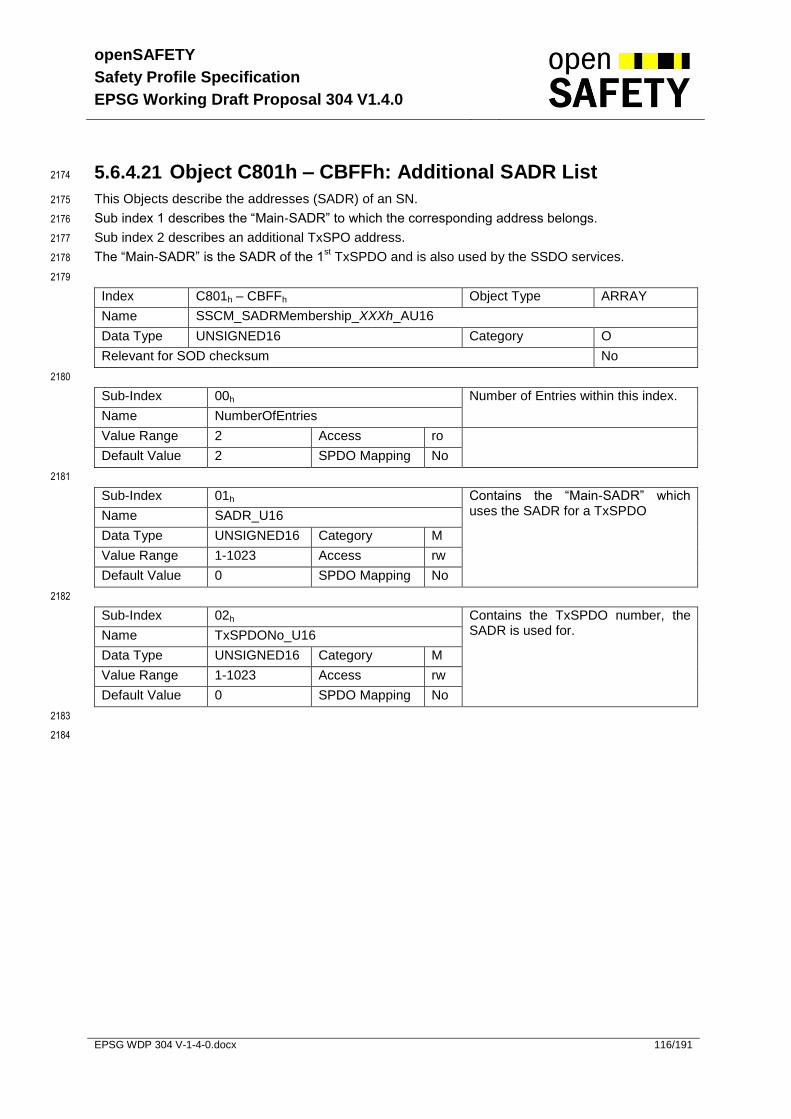
openSAFETY
Safety Profile Specification
EPSG Working Draft Proposal 304 V1.4.0
EPSG WDP 304 V-1-4-0.docx 116/191
5.6.4.21 Object C801h – CBFFh: Additional SADR List 2174
This Objects describe the addresses (SADR) of an SN. 2175
Sub index 1 describes the “Main-SADR” to which the corresponding address belongs. 2176
Sub index 2 describes an additional TxSPO address. 2177
The “Main-SADR” is the SADR of the 1st TxSPDO and is also used by the SSDO services. 2178
2179
Index C801h – CBFFh Object Type ARRAY
Name SSCM_SADRMembership_XXXh_AU16
Data Type UNSIGNED16 Category O
Relevant for SOD checksum No
2180
Sub-Index 00h Number of Entries within this index.
Name NumberOfEntries
Value Range 2 Access ro
Default Value 2 SPDO Mapping No
2181
Sub-Index 01h Contains the “Main-SADR” which uses the SADR for a TxSPDO Name SADR_U16
Data Type UNSIGNED16 Category M
Value Range 1-1023 Access rw
Default Value 0 SPDO Mapping No
2182
Sub-Index 02h Contains the TxSPDO number, the SADR is used for. Name TxSPDONo_U16
Data Type UNSIGNED16 Category M
Value Range 1-1023 Access rw
Default Value 0 SPDO Mapping No
2183
2184
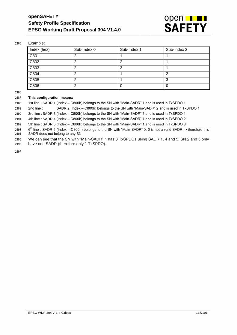
openSAFETY
Safety Profile Specification
EPSG Working Draft Proposal 304 V1.4.0
EPSG WDP 304 V-1-4-0.docx 117/191
Example: 2185
Index (hex) Sub-Index 0 Sub-Index 1 Sub-Index 2
C801 2 1 1
C802 2 2 1
C803 2 3 1
C804 2 1 2
C805 2 1 3
C806 2 0 0
2186
This configuration means: 2187
1st line : SADR 1 (Index – C800h) belongs to the SN with “Main-SADR” 1 and is used in TxSPDO 1 2188
2nd line : SADR 2 (Index – C800h) belongs to the SN with “Main-SADR” 2 and is used in TxSPDO 1 2189
3rd line : SADR 3 (Index – C800h) belongs to the SN with “Main-SADR” 3 and is used in TxSPDO 1 2190
4th line : SADR 4 (Index – C800h) belongs to the SN with “Main-SADR” 1 and is used in TxSPDO 2 2191
5th line : SADR 5 (Index – C800h) belongs to the SN with “Main-SADR” 1 and is used in TxSPDO 3 2192
6th
line : SADR 6 (Index – C800h) belongs to the SN with “Main-SADR” 0, 0 is not a valid SADR -> therefore this 2193
SADR does not belong to any SN 2194
We can see that the SN with “Main-SADR” 1 has 3 TxSPDOs using SADR 1, 4 and 5. SN 2 and 3 only 2195
have one SADR (therefore only 1 TxSPDO). 2196
2197
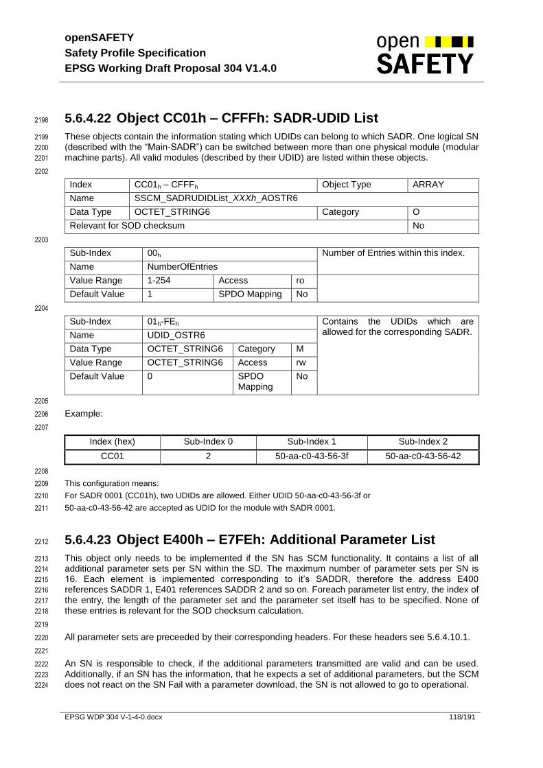
openSAFETY
Safety Profile Specification
EPSG Working Draft Proposal 304 V1.4.0
EPSG WDP 304 V-1-4-0.docx 118/191
5.6.4.22 Object CC01h – CFFFh: SADR-UDID List 2198
These objects contain the information stating which UDIDs can belong to which SADR. One logical SN 2199
(described with the “Main-SADR”) can be switched between more than one physical module (modular 2200
machine parts). All valid modules (described by their UDID) are listed within these objects. 2201
2202
Index CC01h – CFFFh Object Type ARRAY
Name SSCM_SADRUDIDList_XXXh_AOSTR6
Data Type OCTET_STRING6 Category O
Relevant for SOD checksum No
2203
Sub-Index 00h Number of Entries within this index.
Name NumberOfEntries
Value Range 1-254 Access ro
Default Value 1 SPDO Mapping No
2204
Sub-Index 01h-FEh Contains the UDIDs which are allowed for the corresponding SADR. Name UDID_OSTR6
Data Type OCTET_STRING6 Category M
Value Range OCTET_STRING6 Access rw
Default Value 0 SPDO Mapping
No
2205
Example: 2206
2207
Index (hex) Sub-Index 0 Sub-Index 1 Sub-Index 2
CC01 2 50-aa-c0-43-56-3f 50-aa-c0-43-56-42
2208
This configuration means: 2209
For SADR 0001 (CC01h), two UDIDs are allowed. Either UDID 50-aa-c0-43-56-3f or 2210
50-aa-c0-43-56-42 are accepted as UDID for the module with SADR 0001. 2211
5.6.4.23 Object E400h – E7FEh: Additional Parameter List 2212
This object only needs to be implemented if the SN has SCM functionality. It contains a list of all 2213
additional parameter sets per SN within the SD. The maximum number of parameter sets per SN is 2214
16. Each element is implemented corresponding to it’s SADDR, therefore the address E400 2215
references SADDR 1, E401 references SADDR 2 and so on. Foreach parameter list entry, the index of 2216
the entry, the length of the parameter set and the parameter set itself has to be specified. None of 2217
these entries is relevant for the SOD checksum calculation. 2218
2219
All parameter sets are preceeded by their corresponding headers. For these headers see 5.6.4.10.1. 2220
2221
An SN is responsible to check, if the additional parameters transmitted are valid and can be used. 2222
Additionally, if an SN has the information, that he expects a set of additional parameters, but the SCM 2223
does not react on the SN Fail with a parameter download, the SN is not allowed to go to operational. 2224

openSAFETY
Safety Profile Specification
EPSG Working Draft Proposal 304 V1.4.0
EPSG WDP 304 V-1-4-0.docx 119/191
2225
Index E400h – E7FEh Object Type ARRAY
Name SSCM_ADDPARAList_XXXh_ADO
Data Type DOMAIN Category C
Relevant for SOD checksum No
2226
Sub-Index 00h Number of Entries within this index.
Name NumberOfEntries
Value Range 0x00-0x10 Access ro
Default Value 0 SPDO Mapping No
2227
Sub-Index 0x01-0x11 Contains the first parameter set for this entry Name ParameterSet
Data Type DOMAIN Category O
Value Range DOMAIN Access rw
Default Value SPDO Mapping No
2228

openSAFETY
Safety Profile Specification
EPSG Working Draft Proposal 304 V1.4.0
EPSG WDP 304 V-1-4-0.docx 120/191
5.6.5 Safety related PDO Mapping 2229
The real-time data transfer is performed by means of openSAFETY Process Data Objects (SPDO). 2230
Data length and mapping of application objects into SPDOs is determined by the corresponding SPDO 2231
mapping structures within the openSAFETY Object Dictionary. The mapping of application objects into 2232
an SPDO may be transmitted to a device during the device configuration process by applying the 2233
SSDO services to the corresponding entries of the Object Dictionary. 2234
2235
The length of SPDOs of a device is application-specific and has to be specified via the corresponding 2236
mapping object. 2237
2238
There are two uses for SPDOs. The first is data transmission and the second data reception. Transmit 2239
SPDOs (TxSPDOs) and Receive SPDOs (RxSPDOs) can be distinguished. Devices supporting 2240
TxSPDOs are SPDO producers and devices which are able to receive SPDOs are called SPDO 2241
consumers. 2242
2243
SPDOs are described by the SPDO communication parameter and the SPDO mapping parameter. 2244
For each SPDO, the pair of communication and mapping parameters is mandatory. The structures of 2245
this data types are explained. 2246
2247
SPDO communication parameter describes the communication capabilities of the SPDO. 2248
SPDO mapping parameter describes mapping for each object contained in SPDO payload data 2249
to object dictionary entries and vice versa 2250
2251
SPDO mapping may be variable or static. Static mapping is pre-defined by the vendor and may not be 2252
modified in any way. Variable mapping may be configured during commissioning. 2253
5.6.6 Transmit SPDOs 2254
The TxSPDO communication parameters are described by indices 1C00h – 1FFEh 2255
(SPDO_TxCommParam_XXXh_REC). An SN can support up to 1023 TxSPDOs. Only the 2256
implementation of the first TxSPDO is mandatory. The amount of additional TxSPDOs is vendor 2257
specific. The TxSPDO mapping parameters are described by indices C000h – C3FEh 2258
(SPDO_TxMappParam_XXXh_AU32). The data to be transmitted will be assembled according to the 2259
corresponding mapping data. 2260
2261
Sending SPDO data is implicitly limited to the operational state. 2262
2263
Refer to chapter 5.6 for the corresponding entries within the SOD. 2264
2265

openSAFETY
Safety Profile Specification
EPSG Working Draft Proposal 304 V1.4.0
EPSG WDP 304 V-1-4-0.docx 121/191
5.6.7 Receive SPDOs 2266
The RxSPDO communication parameters are described by indices 1400h – 17FEh 2267
(RxSPDOCommParam_XXXh_REC). An SN can support up to 1023 RxSPDOs. The implementation 2268
of RxSPDOs is optional (e.g. an input module, which is a simple producer, does not need to have a 2269
RxSPDO). The RxSPDO mapping parameters are described by indices 1800h – 1BFEh 2270
(SPDO_RxMappParam_XXXh_AU32). The received data will be transferred to the communication 2271
objects assigned to them by the RxSPDO mapping parameters. The application accesses the 2272
received SPDO data by reading out these communication objects. 2273
2274
Receiving SPDO data is implicitly limited to the operational state. 2275
2276
Refer to chapter 5.6 for the corresponding entries within the SOD. 2277
5.6.8 SPDO Mapping Parameter 2278
The indices 1800h – 1BFEh (SPDO_TxMappParam_XXXh_AU32) and C000h – C3FEh 2279
(SPDO_RxMappParam_XXXh_AU32) contain the mapping parameters for transmitting and receiving 2280
SPDOs. For both indices, sub-index 0 contains the number of valid mapping entries which is also the 2281
number of communication variables (SOD entries) to be transmitted/received. The sub-indices 01h to 2282
‘number of entries’ contain information about the mapped application variables. These entries describe 2283
the SPDO contents by their index, sub-index and length (see Tab. 59). All three values are 2284
hexadecimal. The length entry contains the length of the object in bits (01h – FFh). This parameter can 2285
be used to check the overall mapping length. 2286
2287
The structure of a mapping entry (sub-index 01h – FEh) is as follows: 2288
b31 – b16 b15 – b8 b7 – b0
Index (16bit) sub-index (8bit) data length (8bit)
Tab. 59 Structure of SPDO mapping entry 2289
The commissioner is responsible for the correctness of the mapping data. If objects are mapped which 2290
may not be mapped according to the object attribute, the SN will not change to Operational. If data 2291
within a RxSPDO is not used by the consumer, it may be mapped to the data types ( index 0001h – 2292
0007h ). They serve as “dummy entries”. The corresponding data within the RxSPDO is not evaluated 2293
by the device. This feature is useful if a TxSPDO is used for several consumers, each only utilizing 2294
parts of the transmitted data. It is not possible to map those “dummy entries” into a TxSPDO. 2295

openSAFETY
Safety Profile Specification
EPSG Working Draft Proposal 304 V1.4.0
EPSG WDP 304 V-1-4-0.docx 122/191
5.6.9 SPDO Mapping Example 2296
2297
Fig. 41. SPDO mapping example 2298
The SN with “Main-SADR” 12 is an input module with 32 digital inputs. 2299
The SN with “Main-SADR” 13 is an output module with 8 digital outputs. 2300
The SN with “Main-SADR” 14 is an output module with 16 digital outputs. 2301
2302
Assume that the inputs are available at SOD-index 6000h sub-indices 01h – 04h and that the data 2303
type is UNSIGNED8. Also assume that the outputs need to be written to SOD index 6200h sub-indices 2304
01h respectively 01h and 02h. The data type again is UNSIGNED8. Then, assume that SN 13 needs 2305
the information from the 3rd
input byte and SN 14 needs the information from the 1st and 4
th input byte. 2306
2307
The communication parameters from SN12 (producer) looks as following: 2308
Index Sub-Index Data Description
1C00h 1 12 The TxSPDO is broadcast under the SADR 12
Tab. 60 Mapping example table 1 2309
2310
The mapping of SN 12 (producer) may be specified as follows: 2311
Index Sub-Index Data Description
C000h 0 4 four valid mapping entries
1 60 00 01 08 h Mapping entry 1: 8bits of the object from index 6000h sub-index 1 are mapped into the SPDO
2 60 00 02 08 h Mapping entry 2: 8bits of the object from index 6000h sub-index 2 are mapped into the SPDO
3 60 00 03 08 h Mapping entry 3: 8bits of the object from index 6000h sub-index 3 are mapped into the SPDO
4 60 00 04 08 h Mapping entry 4: 8bits of the object from index 6000h sub-index 4 are mapped into the SPDO
Tab. 61 Mapping example table 2 2312
2313
SN
CN with multiple SNs
SN
MN
SCM
FM
CN
Modular CN with multiple SNs
SN
Direct Communication between a SN and a
specific bit of another SN
SADR 14
SADR 12
SADR 13
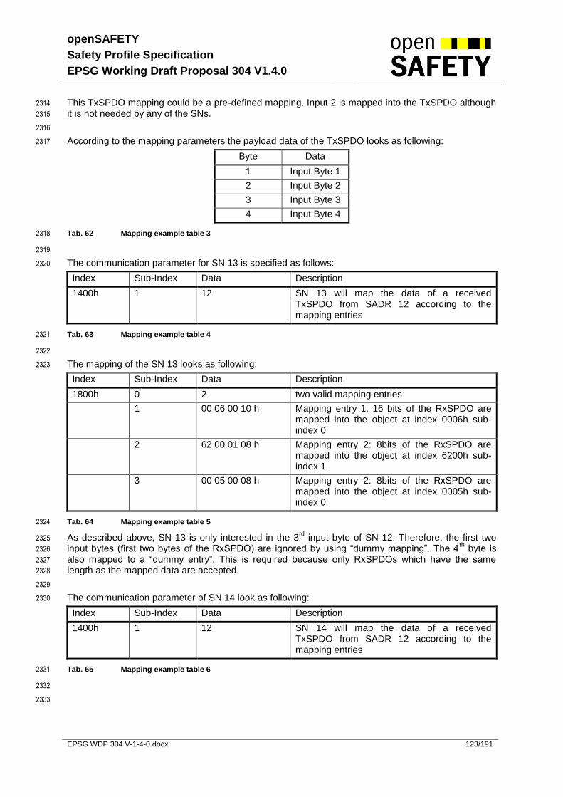
openSAFETY
Safety Profile Specification
EPSG Working Draft Proposal 304 V1.4.0
EPSG WDP 304 V-1-4-0.docx 123/191
This TxSPDO mapping could be a pre-defined mapping. Input 2 is mapped into the TxSPDO although 2314
it is not needed by any of the SNs. 2315
2316
According to the mapping parameters the payload data of the TxSPDO looks as following: 2317
Byte Data
1 Input Byte 1
2 Input Byte 2
3 Input Byte 3
4 Input Byte 4
Tab. 62 Mapping example table 3 2318
2319
The communication parameter for SN 13 is specified as follows: 2320
Index Sub-Index Data Description
1400h 1 12 SN 13 will map the data of a received TxSPDO from SADR 12 according to the mapping entries
Tab. 63 Mapping example table 4 2321
2322
The mapping of the SN 13 looks as following: 2323
Index Sub-Index Data Description
1800h 0 2 two valid mapping entries
1 00 06 00 10 h Mapping entry 1: 16 bits of the RxSPDO are mapped into the object at index 0006h sub-index 0
2 62 00 01 08 h Mapping entry 2: 8bits of the RxSPDO are mapped into the object at index 6200h sub-index 1
3 00 05 00 08 h Mapping entry 2: 8bits of the RxSPDO are mapped into the object at index 0005h sub-index 0
Tab. 64 Mapping example table 5 2324
As described above, SN 13 is only interested in the 3rd
input byte of SN 12. Therefore, the first two 2325
input bytes (first two bytes of the RxSPDO) are ignored by using “dummy mapping”. The 4th byte is 2326
also mapped to a “dummy entry”. This is required because only RxSPDOs which have the same 2327
length as the mapped data are accepted. 2328
2329
The communication parameter of SN 14 look as following: 2330
Index Sub-Index Data Description
1400h 1 12 SN 14 will map the data of a received TxSPDO from SADR 12 according to the mapping entries
Tab. 65 Mapping example table 6 2331
2332
2333

openSAFETY
Safety Profile Specification
EPSG Working Draft Proposal 304 V1.4.0
EPSG WDP 304 V-1-4-0.docx 124/191
The mapping of the SN 14 looks as following: 2334
Index Sub-Index Data Description
1800h 0 3 three valid mapping entries
1 62 00 01 08 h Mapping entry 1: 8bits of the RxSPDO are mapped into the object at index 6200h sub-index 1
2 00 06 00 10 h Mapping entry 2: 16 bits of the RxSPDO are mapped into the object at index 0006h sub-index 0
3 62 00 02 08 h Mapping entry 3: 8bits of the RxSPDO are mapped into the object at index 6200h sub-index 2
Tab. 66 Mapping example table 7 2335
2336
As described above, SN 14 is only interested in input bytes 1 and 4 of SN 12. Input bytes 2 and 3 2337
(respectively byte 2 and 3 of the RxSPDO) are ignored by using dummy mapping. 2338
5.6.10 SPDO Error Handling 2339
Non-Map able Application Object 2340
The SN has to ensure that only mappable application objects will be accepted. If a non-mappable 2341
object is recognized, the SN may not store this mapping data into the SOD. As a result of this, the 2342
checksum of the SOD will be different from the expected checksum stored on the SCM and therefore 2343
the SN will not be switched to the operational state (see 5.7.13). 2344
Unexpected length of RxSPDO 2345
If an SPDO is received with a length that is not equal to the length of the mapped data, the SPDO has 2346
to be ignored. Additional diagnosis data may be provided via the SOD. 2347
2348

openSAFETY
Safety Profile Specification
EPSG Working Draft Proposal 304 V1.4.0
EPSG WDP 304 V-1-4-0.docx 125/191
5.7 State - / Sequence Diagrams 2349
5.7.1 Safety Process Data Object (SPDO) 2350
5.7.1.1 Safety Process Data Object Producer (TxSPDO) 2351
Tx
IDLE
(delta-t expired) OR
((data(new) exists) AND (CT
increased))
data sent
2352
Fig. 42. State diagram “TxSPDO” 2353
2354
2355
Fig. 43. SPDO communication producer 2356
Item Description Min Value Max value SOD
data_new New data from safety related application or new TRes received
- - -
t Internal time [CT] 0 65535 -
t Refresh prescale [CT] 1 32767 Object Index 1C00h – 1FFEh
sub index 2h (see 5.6.4.17)
t1 Time difference of new data [CT] >0 t -
Tab. 67 SPDO communication producer item description 2357
Description: The producer starts sending its data cyclically or on state changes when switching to 2358
operational. The refresh time for sending the data can be adjusted within the SOD. 2359
State Description
Tx Sending data
IDLE Wait until refresh time elapsed or new data available
Producer
data & t
data & (t+t)
data_new & (t+t+t1)
t
Event Non safe communi-
cation layer
data_new
data & t
data & (t+t)
data_new & (t+t+t1)

openSAFETY
Safety Profile Specification
EPSG Working Draft Proposal 304 V1.4.0
EPSG WDP 304 V-1-4-0.docx 126/191
Tab. 68 SPDO communication producer state description 2360
5.7.1.2 Safety Process Data Object Consumer (RxSPDO) 2361
2362
Fig. 44. State diagram “RxSPDO” 2363
2364
2365
Fig. 45. SPDO communication consumer 2366
2367
Consumer
data1 & t1
data1 & t1
data1 & t2
data2 & t2
data2(corrupted) & t2
data2(corrupted) & t3
data2(corrupted) & t3
data2(corrupted) & t3
data2 & t3
Non safe communi-cation layer
data1 & t1
data1 & t2
data2 & t2
data2 & t3
new data, new time, process data
old data, old time, ignore
old data, new time, process data
new data, old time, ignore
data corrupted, ignore
data corrupted, ignore
SCT elapsed, set RxSPDO data to safe state,
new data, new time, process data
IDLE
Process data
data received
SCT elapsed
Set RxSPDO data to safe
state
Write diagnose data
to SOD
Start SCT
Data
invalid
Data
valid
data received Time synchronization failure
Consumer
data1 & t1
data1 & t1
data1 & t2
data2 & t2
data2(corrupted) & t2
data2(corrupted) & t3
data2(corrupted) & t3
data2(corrupted) & t3
data2 & t3
Non safe communi-cation layer
data1 & t1
data1 & t2
data2 & t2
data2 & t3
new data, new time, process data
old data, old time, ignore
old data, new time, process data
new data, old time, ignore
data corrupted, ignore
data corrupted, ignore
SCT elapsed, set RxSPDO data to safe state,
new data, new time, process data

openSAFETY
Safety Profile Specification
EPSG Working Draft Proposal 304 V1.4.0
EPSG WDP 304 V-1-4-0.docx 127/191
2368
Item Description Min Value Max value SOD
SCT Safety control time [CT] 1 UNSIGNED32-
Object 1400h – 17FEh sub index 2h (see 5.6.4.15)
Tab. 69 SPDO communication consumer item description 2369
2370
Description: This state diagram is performed for each RxSPDO. The consumer gets cyclic data 2371
from a producer. The data will be processed. Processing data includes time 2372
synchronization and time validation, see 5.7.1.2.1. If a consumer receives valid data 2373
from a producer, the SCT timer is restarted. If the SCT timer elapses, all data related 2374
to the RxSPDO will be set to a safe state. 2375
2376
State Description
IDLE Waiting for data.
Process data Performing timing validation and time synchronization. Process data according to SPDO mapping.
Start SCT Reset the SCT.
Write diagnose data to SOD The diagnose data has to be available for the user. This is made through the SOD.
Set RxSPDO data to safe state All data related to the producer will be set to zero.
Tab. 70 SPDO communication consumer state description 2377
2378

openSAFETY
Safety Profile Specification
EPSG Working Draft Proposal 304 V1.4.0
EPSG WDP 304 V-1-4-0.docx 128/191
5.7.1.2.1 Process Data 2379
Validate
RxSPDO
frame
Process
TRes
Data with TRes received
Check
propagation
delay
deviation
Data without
TRes received
Validate
timestamp
CT valid or
no CT for validation available
CT is not valid
Data is ok
[propagation delay deviation is ok]
Map data
CT for validation available
/ store CT for next validation
Set RxSPDO
to safe state
no CT for
validation available
/ store CT for next validation
Time synchronization failure
[propagation delay too short]
/ delete CT for validation Data is invalid
[propagation delay too long]
2380
Fig. 46. State diagram “Process Data” 2381
Item Description Min Value Max value SOD
CT Consecutive time field 0 65535 -
TRes Time synchronization response, consists of TR (Time Request Distinctive Number Field) and TADR (Time Request Address) within the safety frame
- - -
Tab. 71 SPDO communication consumer telegram validation item description 2382
State Description
Validate timestamp If the timestamp (CT) is equal to or less than the timestamp of the previously valid telegram, the telegram will be ignored.
Validate RxSPDO frame Checks if the frame contains time synchronization data for this node.
Process TRes See 5.7.2.6
Check propagation delay deviation Checks if the timestamp is valid or not.
Set RxSPDO to safe state All cyclic data related to this RxSPDO is set to the safe state
Map data Writes the data into the SOD according to the RxSPDO mapping

openSAFETY
Safety Profile Specification
EPSG Working Draft Proposal 304 V1.4.0
EPSG WDP 304 V-1-4-0.docx 129/191
Tab. 72 SPDO communication consumer telegram validation state description 2383
5.7.2 Time Synchronization and Validation 2384
To verify the performance of the non safe communication layer, openSAFETY uses a combined time 2385
synchronization and validation sequences. Because of tolerances of the hardware clocks within the 2386
safety nodes, this has to be done cyclically. The following figure shows the basic sequences how the 2387
time synchronization and validation are carried out. 2388
2389
2390
Fig. 47. Time Synchronization and Validation 2391
2392
Time Validation
Time Synchronization
Producer Consumer
T RefProducer T RefConsumer
T SPDOConsumer
T SPDOConsumer
T SPDOConsumer
T SPDOConsumer
T SPDOProducer
T SPDOProducer
T SPDOProducer
T SPDOProducer

openSAFETY
Safety Profile Specification
EPSG Working Draft Proposal 304 V1.4.0
EPSG WDP 304 V-1-4-0.docx 130/191
5.7.2.1 Time Synchronization 2393
The consumer starts the sequence by sending a set of Time Requests (TReq) to the producer. This is 2394
done by using a TxSPDO. When receiving the first TReq, the producer creates a “new data event” 2395
(see 5.7.1.1) to reply to the request as soon as possible with the corresponding set of Time 2396
Responses (TRes). Then the first received TRes within the consumer is checked against the minimum 2397
and maximum allowed TSync propagation delay. If the delay is shorter then the minimum allowed 2398
delay, the consumer must enter the fail safe state, because in this case the best case TRes delay 2399
parameter has been set wrong. If the delay is longer then the maximum allowed delay, the time 2400
response is ignored. If delay is within the given limits, time synchronization was successful and the 2401
consumer memorizes the internal T RefProducer and T RefConsumer values. 2402
2403
The following figure shows in detail the Time Synchronization Sequence: 2404
2405
2406
Fig. 48. Time Synchronization Detail 2407
2408
Time Validation
Time Synchronization
Producer Consumer
Best case TRes delay
T RefProducer T RefConsumer Minimum allowed TSync propagation delay
Maximum allowed TSync propagation delay

openSAFETY
Safety Profile Specification
EPSG Working Draft Proposal 304 V1.4.0
EPSG WDP 304 V-1-4-0.docx 131/191
2409
Item Description Min Value
Max value
SOD
T RefProducer value of CT field within the TRes service supplied by the producer
0 65535 -
best case TRes delay
user defined value to define the best case minimum time needed to transfer the time request from the consumer to the producer and to set up the time response within the producer. This value is used to calculate the SPDO propagation delay. If the user assumes a larger value as it is in reality, the time validation would not recognize impermissible delays in the SPDO propagation.
0 65535 Object index 1400h – 17FEh sub index Ah (see 5.6.4.15)
T RefConsumer Time Request start time [CT] + best case TRes delay [CT] this value is calculated within the consumer and gives a time reference within the consumers CT to T RefProducer.
> best case TRes delay
65535 -
Minimum allowed TSync
propagation delay
Minimum allowed propagation delay for time synchronization [CT]
1 65535 Object index 1400h – 17FEh
sub index 6h (see 5.6.4.15)
Maximum allowed TSync
propagation delay
Maximum allowed propagation delay for time synchronization [CT]
1 65535 Object index 1400h – 17FEh
sub index 7h (see 5.6.4.15)
Tab. 73 Time synchronization item description 2410
2411

openSAFETY
Safety Profile Specification
EPSG Working Draft Proposal 304 V1.4.0
EPSG WDP 304 V-1-4-0.docx 132/191
5.7.2.2 Time Validation 2412
After successful time synchronization, the consumer is able to receive SPDOs and to calculate the 2413
propagation delay for them: 2414
SPDO propagation delay = (T SPDOConsumer - T RefConsumer) - (T SPDOProducer -T RefProducer) 2415
The result will be checked against the minimum and maximum allowed SPDO propagation delay. If 2416
the delay is shorter then the minimum allowed delay, the consumer must enter the fail safe state, 2417
because in this case the best case TRes delay parameter has been set wrong. If the delay is longer 2418
then the maximum allowed delay, the SPDO is ignored. If delay is within the given limits, the SPDO is 2419
processed. 2420
2421
The following figures shows in detail the Time Validation Sequences: 2422
2423
Fig. 49. Time Validation Detail 2424
2425
Time Validation
Time Synchronization
Producer Consumer
T RefProducer T RefConsumer
T SPDOConsumer
T SPDOConsumer
T SPDOConsumer
T SPDOConsumer
T SPDOProducer
T SPDOProducer
T SPDOProducer
T SPDOProducer
T_SPDO_to_RefProducer T_SPDO_to_RefConsumer
SPDO Propagation Delay = T_SPDO_to_RefConsumer -T_SPDO_to_RefProducer

openSAFETY
Safety Profile Specification
EPSG Working Draft Proposal 304 V1.4.0
EPSG WDP 304 V-1-4-0.docx 133/191
2426
Fig. 50. Time Validation, Propagation Delay Explanation Limits 2427
Item Description Min Value
Max value
SOD
T SPDOProducer value of CT field within the SPDO supplied by the producer
0 65535 -
T SPDOConsumer CT value within the consumer when receiving the SPDO
0 65535 -
SPDO propagation delay
calculated propagation delay using the time references of the previous time synchronization: (T SPDOConsumer - T RefConsumer) - (T SPDOProducer -T RefProducer)
0 65535 -
Minimum allowed SPDO
propagation delay
Minimum allowed propagation delay for SPDO [CT]
1 65535 Object index 1400h – 17FEh sub index 8h (see 5.6.4.15)
Maximum allowed SPDO
propagation delay
Maximum allowed propagation delay for SPDO[CT]
1 65535 Object index 1400h – 17FEh sub index 9h (see 5.6.4.15)
Tab. 74 Time validation item description 2428
2429
Time Validation
delay to short, enter FAIL Safe Sate
Time Synchronization
Producer Consumer
T RefConsumer
delay to large, SPDO is ignored
Maximum allowed SPDO propagation delay
Minimum allowed SPDO propagation delay

openSAFETY
Safety Profile Specification
EPSG Working Draft Proposal 304 V1.4.0
EPSG WDP 304 V-1-4-0.docx 134/191
5.7.2.3 Time Synchronization Operation 2430
To increase the immunity of openSAFETY against data loss within the non safe communication layer, 2431
the TReq and TRes services are sent as bundle of single services. 2432
The consumer sends m time requests (TxSPDO) to the producer containing the TR (Time Request 2433
Distinctive Number). This number is incremented with each time request. The producer receives the 2434
time request from a specific node and starts answering the time request. The response to a time 2435
request is to fill the TADR (SADR of the requesting node) and the TR field in the cyclic TxSPDO 2436
telegram from the producer. The producer repeats the response for a received time request n times 2437
although new time requests were already received. This ensures that the consumer which initiates the 2438
time request receives the correct answer. During processing the Time Response, the producer ignores 2439
all other time requests corresponding to this TxSPDO regardless the time request comes from the 2440
same consumer or from another one. 2441
If the consumer did not receive the time response within td, the next set of time requests is sent. The 2442
number of time responses per time request, the number of requests per consecutive request set, td 2443
and the timer ts which re-initiates a time request are to be adjusted within the SOD. If the propagation 2444
delay is too long the TRes is ignored, if it is too short, the fail safe state must be entered (see 5.7.2.1). 2445
If a valid TRes was not received within the Time request cycle, a time synchronization failure occurs. 2446
The time synchronization for each producer starts when the consumer is operational and receives the 2447
first RxSPDO from the corresponding producer. 2448
Within a Consumer / Producer relationship, equal CT values are mandatory. 2449
2450
2451
Fig. 51. Time synchronization on a nonsafe network 2452
The above figure shows how a time request and response can look on the bus system. The consumer 2453
sends a time request to one of its producers. This request is repeated m times. The producer answers 2454
the first time request, and it receives and repeats the answer n times. If a producer receives a time 2455
request during the time it is already answering another time request on the corresponding TxSPDO, 2456
Producer Nonsafe communication
layer
Consumer Nonsafe network
TReq (TR=0)
TReq (TR=1)
TReq (TR=2)
m
TRes (TR=2)
n
TRes #1, TR=2
TRes #2, TR=2
Ignore TReq TR=3
TRes #3, TR=2
TRes #4, TR=2
TReq (TR=3)
Nonsafe communication
layer
Propagation delay of time
synchronization
Δt of the producer
Δt of the consumer
TReq received, new_data event
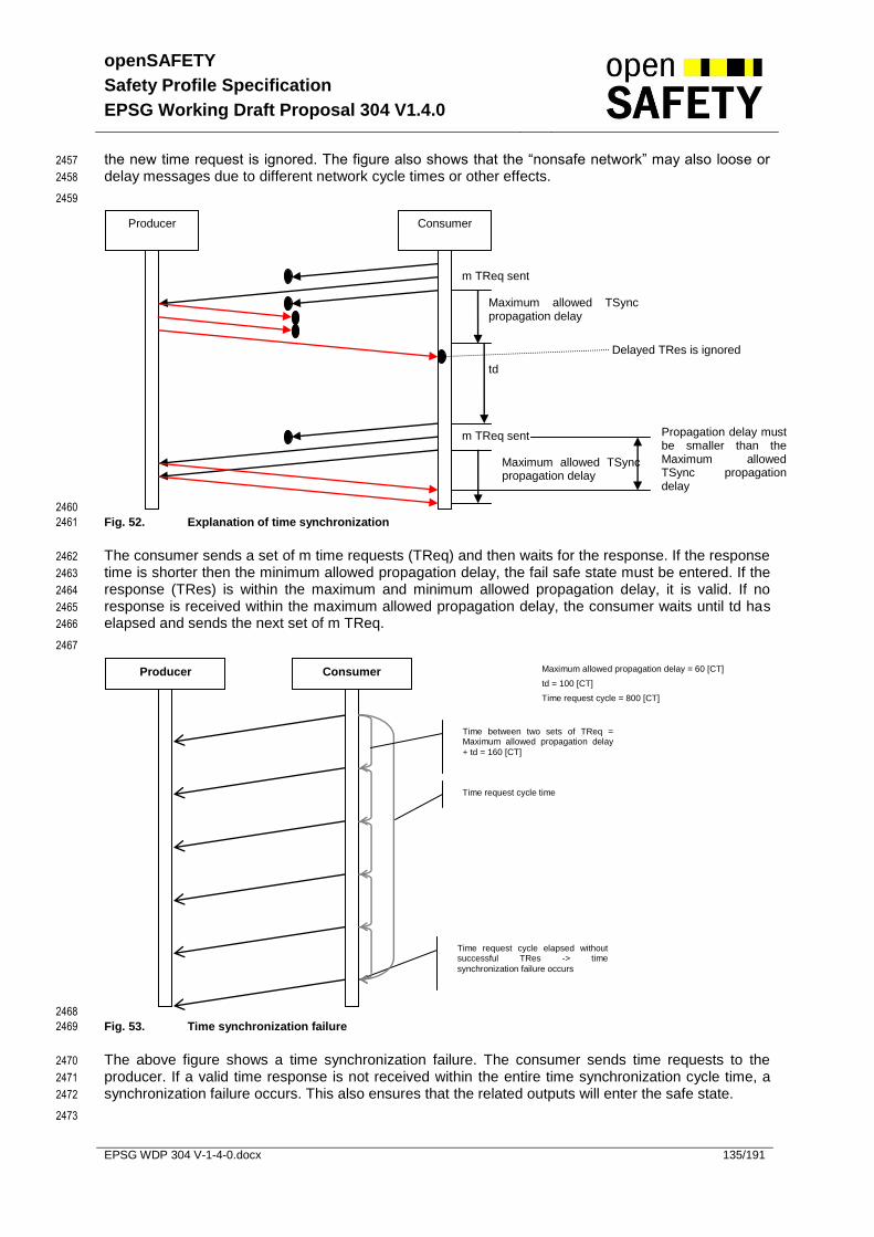
openSAFETY
Safety Profile Specification
EPSG Working Draft Proposal 304 V1.4.0
EPSG WDP 304 V-1-4-0.docx 135/191
the new time request is ignored. The figure also shows that the “nonsafe network” may also loose or 2457
delay messages due to different network cycle times or other effects. 2458
2459
2460
Fig. 52. Explanation of time synchronization 2461
The consumer sends a set of m time requests (TReq) and then waits for the response. If the response 2462
time is shorter then the minimum allowed propagation delay, the fail safe state must be entered. If the 2463
response (TRes) is within the maximum and minimum allowed propagation delay, it is valid. If no 2464
response is received within the maximum allowed propagation delay, the consumer waits until td has 2465
elapsed and sends the next set of m TReq. 2466
2467
2468
Fig. 53. Time synchronization failure 2469
The above figure shows a time synchronization failure. The consumer sends time requests to the 2470
producer. If a valid time response is not received within the entire time synchronization cycle time, a 2471
synchronization failure occurs. This also ensures that the related outputs will enter the safe state. 2472
2473
Producer Consumer Maximum allowed propagation delay = 60 [CT]
td = 100 [CT]
Time request cycle = 800 [CT]
Time request cycle elapsed without successful TRes -> time
synchronization failure occurs
Time between two sets of TReq = Maximum allowed propagation delay
+ td = 160 [CT]
Time request cycle time
Producer Consumer
m TReq sent
Maximum allowed TSync propagation delay
td
Propagation delay must be smaller than the Maximum allowed TSync propagation delay
m TReq sent
Maximum allowed TSync propagation delay
Delayed TRes is ignored

openSAFETY
Safety Profile Specification
EPSG Working Draft Proposal 304 V1.4.0
EPSG WDP 304 V-1-4-0.docx 136/191
Item Description Min Value
Max value SOD
n Number of TRes from Producer 1 255 Object index 1C00h – 1FFEh sub index 3h (see 5.6.4.17)
TR Time Request Distinctive Number
Consumer: To be incremented each TReq
0 63 -
m Number of consecutive TReq from consumer
1 63 Object index 1400h – 17FEh sub index 3h (see 5.6.4.15)
td Time delay between two TReq blocks [CT]
0 UNSIGNED32 Object index 1400h – 17FEh sub index 4h (see 5.6.4.15)
ts Time delay for new synchronization [CT]. The delay between successful time synchronization and the next TReq.
1 UNSIGNED32 Object index 1400h – 17FEh sub index 5h (see 5.6.4.15)
Time request cycle [CT] 1 UNSIGNED32 Object index 1400h – 17FEh sub index Bh (see 5.6.4.15)
Maximum allowed TSync propagation delay
1 65535 Object index 1400h – 17FEh sub index 7h (see 5.6.4.15)
Tab. 75 Extended Time synchronization item description 2474
2475
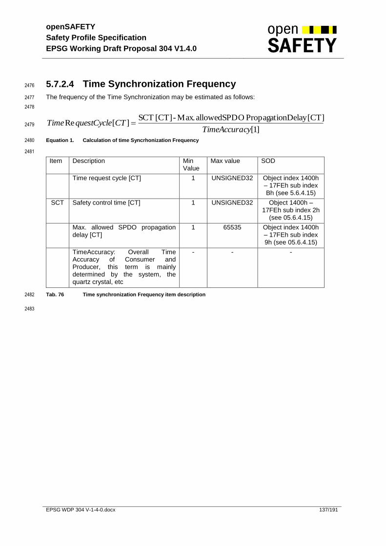
openSAFETY
Safety Profile Specification
EPSG Working Draft Proposal 304 V1.4.0
EPSG WDP 304 V-1-4-0.docx 137/191
5.7.2.4 Time Synchronization Frequency 2476
The frequency of the Time Synchronization may be estimated as follows: 2477
2478
]1[
nDelay[CT]Propagatio OallowedSPD Max.- [CT] SCT][Re
cyTimeAccuraCTquestCycleTime 2479
Equation 1. Calculation of time Syncrhonization Frequency 2480
2481
Item Description Min Value
Max value SOD
Time request cycle [CT] 1 UNSIGNED32 Object index 1400h – 17FEh sub index Bh (see 5.6.4.15)
SCT Safety control time [CT] 1 UNSIGNED32 Object 1400h – 17FEh sub index 2h
(see 05.6.4.15)
Max. allowed SPDO propagation delay [CT]
1 65535 Object index 1400h – 17FEh sub index 9h (see 05.6.4.15)
TimeAccuracy: Overall Time Accuracy of Consumer and Producer, this term is mainly determined by the system, the quartz crystal, etc
- - -
Tab. 76 Time synchronization Frequency item description 2482
2483
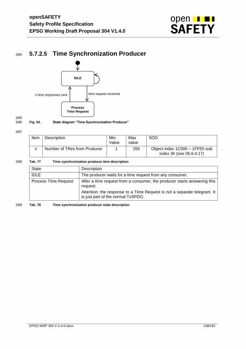
openSAFETY
Safety Profile Specification
EPSG Working Draft Proposal 304 V1.4.0
EPSG WDP 304 V-1-4-0.docx 138/191
5.7.2.5 Time Synchronization Producer 2484
2485
Fig. 54. State diagram “Time Synchronization Producer” 2486
2487
Item Description Min Value
Max value
SOD
n Number of TRes from Producer 1 255 Object index 1C00h – 1FFEh sub index 3h (see 05.6.4.17)
Tab. 77 Time synchronization producer item description 2488
State Description
IDLE The producer waits for a time request from any consumer.
Process Time Request After a time request from a consumer, the producer starts answering this request.
Attention: the response to a Time Request is not a separate telegram. It is just part of the normal TxSPDO.
Tab. 78 Time synchronization producer state description 2489
IDLE
Process Time Request
time request received n time responses sent

openSAFETY
Safety Profile Specification
EPSG Working Draft Proposal 304 V1.4.0
EPSG WDP 304 V-1-4-0.docx 139/191
5.7.2.6 Time Synchronization Consumer 2490
2491
Fig. 55. State diagram “Time Synchronization Consumer” 2492
2493
IDLE
Send
Time Request
m TReq sent and maximum
propagation delay expired
TRes received and propagation delay
Ok
Δt or new data [not m Treq sent] / increase TR
TReq sent
Wait td
Sync Ok
/reset m, reset time request cycle time
td expired
Time request cycle time expired
Time request cycle time expired or number of not answered TR expired or (TRes received and Propagation delay is shorter then minimum allowed propagation delay)
Wait ts ts expired
Time synchronization failure occurred
(refer to Tab. 68)

openSAFETY
Safety Profile Specification
EPSG Working Draft Proposal 304 V1.4.0
EPSG WDP 304 V-1-4-0.docx 140/191
2494
Item Description Min Value
Max Value
SOD
TReq Time synchronization request
- - -
m Number of consecutive TReq from consumer
1 63 Object index 1400h – 17FEh sub index 3h (see 05.6.4.15)
TR Time Request Distinctive Number Field
0 63 -
t TxSPDO refresh prescale [CT]
1 32767 Object index 1400h – 17FEh sub index 2h (see 05.6.4.15)
td Time delay between two TReq blocks [CT]
0 UNSIGNED32
Object index 1400h – 17FEh sub index 4h (see 5.6.4.15)
ts Time delay for new synchronization [CT]. The delay between successful time synchronization and the next TReq.
1 UNSIGNED32
Object index 1400h – 17FEh sub index 5h (see 5.6.4.15)
Minimum allowed propagation delay for time synchronization [CT]
1 65535 Object index 1400h – 17FEh sub index 6h (see 5.6.4.15)
Maximum allowed propagation delay for time synchronization [CT]
1 65535 Object index 1400h – 17FEh sub index 7h (see 5.6.4.15)
Time request cycle [CT] 1 UNSIGNED32
Object index 1400h – 17FEh sub index Bh (see 5.6.4.15)
Tab. 79 Time synchronization consumer item description 2495
State Description
Send Time Request Sending the time request to the corresponding producer.
IDLE Waiting for TRes.
Wait td Waiting until td expired. All received TRes are ignored.
Wait ts Waiting until ts expired. All received TRes are ignored.
Sync Ok Synchronization Ok. Reset m reset time request cycle time. Reset number of not answered TR.
Tab. 80 Time synchronization consumer state description 2496
2497
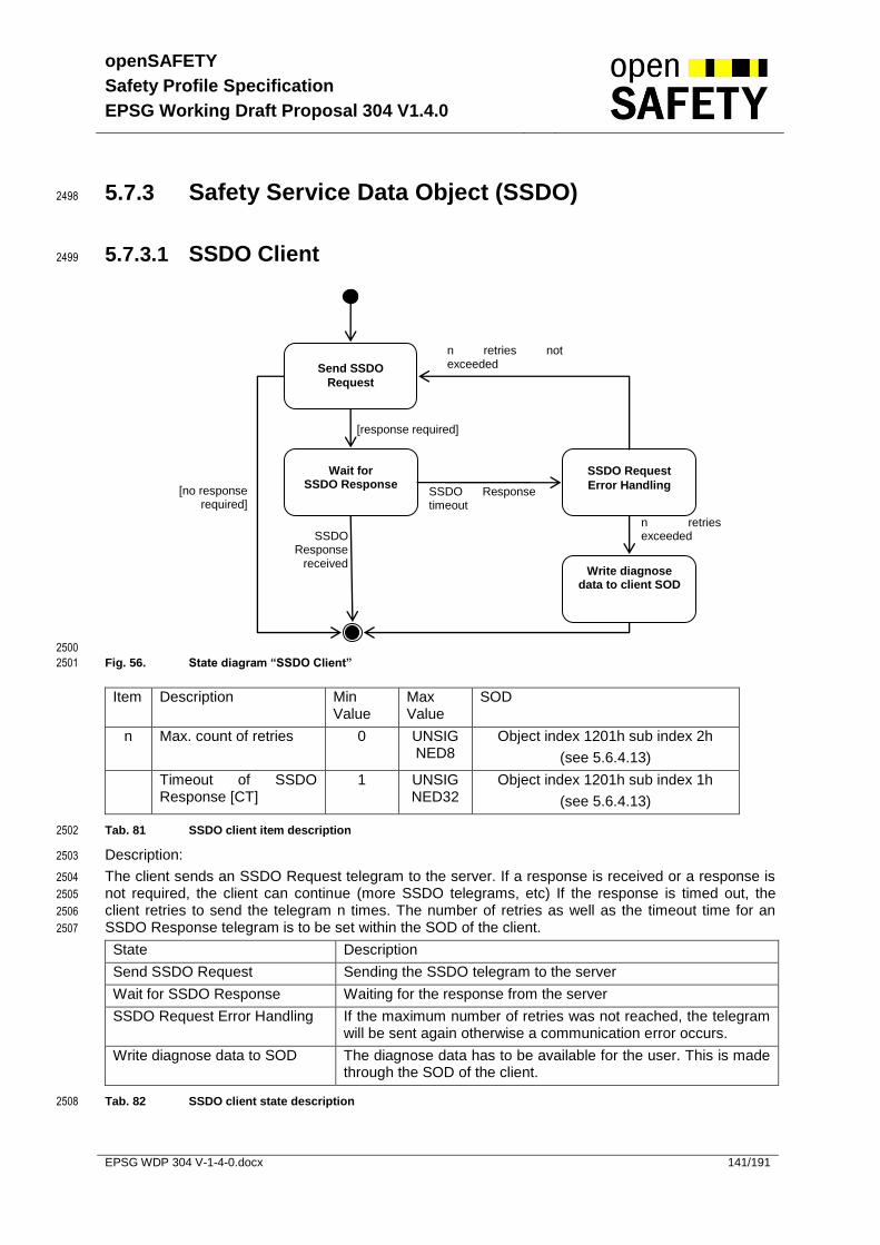
openSAFETY
Safety Profile Specification
EPSG Working Draft Proposal 304 V1.4.0
EPSG WDP 304 V-1-4-0.docx 141/191
5.7.3 Safety Service Data Object (SSDO) 2498
5.7.3.1 SSDO Client 2499
2500
Fig. 56. State diagram “SSDO Client” 2501
Item Description Min Value
Max Value
SOD
n Max. count of retries 0 UNSIGNED8
Object index 1201h sub index 2h
(see 5.6.4.13)
Timeout of SSDO Response [CT]
1 UNSIGNED32
Object index 1201h sub index 1h
(see 5.6.4.13)
Tab. 81 SSDO client item description 2502
Description: 2503
The client sends an SSDO Request telegram to the server. If a response is received or a response is 2504
not required, the client can continue (more SSDO telegrams, etc) If the response is timed out, the 2505
client retries to send the telegram n times. The number of retries as well as the timeout time for an 2506
SSDO Response telegram is to be set within the SOD of the client. 2507
State Description
Send SSDO Request Sending the SSDO telegram to the server
Wait for SSDO Response Waiting for the response from the server
SSDO Request Error Handling If the maximum number of retries was not reached, the telegram will be sent again otherwise a communication error occurs.
Write diagnose data to SOD The diagnose data has to be available for the user. This is made through the SOD of the client.
Tab. 82 SSDO client state description 2508
Send SSDO
Request
Wait for SSDO Response
SSDO Request
Error Handling SSDO Response timeout
n retries not exceeded
SSDO Response
received
n retries exceeded
Write diagnose data to client SOD
[response required]
[no response required]
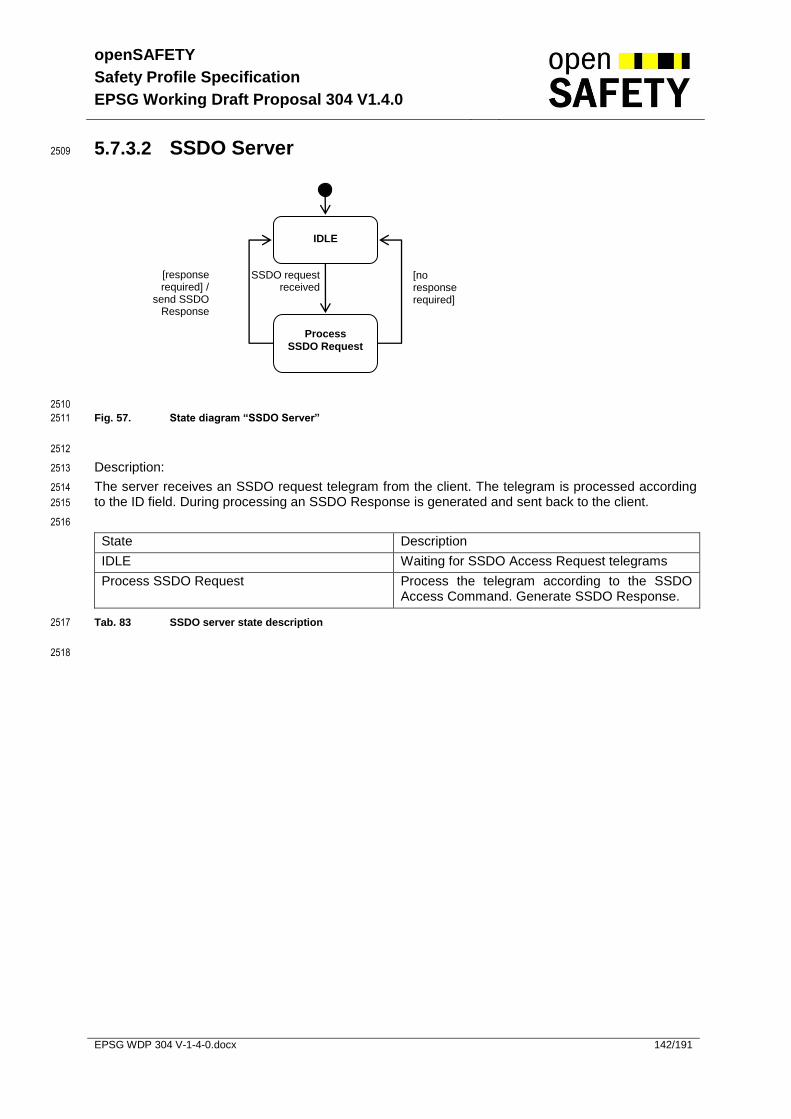
openSAFETY
Safety Profile Specification
EPSG Working Draft Proposal 304 V1.4.0
EPSG WDP 304 V-1-4-0.docx 142/191
5.7.3.2 SSDO Server 2509
2510
Fig. 57. State diagram “SSDO Server” 2511
2512
Description: 2513
The server receives an SSDO request telegram from the client. The telegram is processed according 2514
to the ID field. During processing an SSDO Response is generated and sent back to the client. 2515
2516
State Description
IDLE Waiting for SSDO Access Request telegrams
Process SSDO Request Process the telegram according to the SSDO Access Command. Generate SSDO Response.
Tab. 83 SSDO server state description 2517
2518
IDLE
Process
SSDO Request
SSDO request received
[response required] /
send SSDO Response
[no response required]

openSAFETY
Safety Profile Specification
EPSG Working Draft Proposal 304 V1.4.0
EPSG WDP 304 V-1-4-0.docx 143/191
5.7.4 SOD Access 2519
The SOD Access is based on the SSDO services. The SSDO service is used by the client to access 2520
the SOD (openSAFETY Object Dictionary) within the server. 2521
Write access to the SOD is permitted 2522
in Pre-Operational state for all parameters 2523
in Operational state for user parameters within 0x2800 – 0x2FFF index range. These 2524
parameters may not be part of the SOD CRC. For write access to these parameters it’s not 2525
allowed to use SLIM SSDO Services. 2526
5.7.4.1 SOD Access (expedited) 2527
2528
2529
Fig. 58. Expedited SOD Access 2530
Item Description Min Value
Max Value SOD
n Max. count of retries in series
0 UNSIGNED8 Object index 1201h sub index 2h
(see 5.6.4.13)
Timeout Timeout of SOD Access response
1 UNSIGNED32 Object index 1201h sub index 1h
(see 5.6.4.13)
Tab. 84 SOD Access item description 2531
SOD Access Request (SACmd, SANo, Index, Subindex, Data)
SOD Access Response (SACmd(OK), SANo, Index, Subindex, Data)
SOD Access Request (SACmd, SANo+1, Index, Subindex, Data)
SOD Access Response (SACmd(ERROR), SANo+1, Index, Subindex, Data)
SOD Access Request (SACmd, SANo+3, Index, Subindex, Data)
SOD Access Request (SACmd, SANo+3, Index, Subindex, Data)
SOD Access Response (SACmd(OK), SANo+3, Index, Subindex, Data)
SOD Access Request (SACmd, SANo+4, Index, Subindex, Data)
SOD Access Request (SACmd, SANo+4, Index, Subindex, Data)
SOD Access Request (SACmd, SANo+4, Index, Subindex, Data)
SOD Access Request (SACmd, SANo+4, Index, Subindex, Data)
Server
Access successfully processed.
Client
Error during processing
timeout
n timeouts in series

openSAFETY
Safety Profile Specification
EPSG Working Draft Proposal 304 V1.4.0
EPSG WDP 304 V-1-4-0.docx 144/191
5.7.4.2 SOD Download Access with segmentation 2532
5.7.4.2.1 Client state diagram 2533
2534
Fig. 59. State diagram “Segmented SOD Download Access Client” 2535
2536
Initiate segmented
download
Send data
End segmented
download
Error handling
Segmented download successfully initialized /
reset n, set toggle bit
Segment n sent [remaining segments = 1]
/ invert toggle bit
Segment n sent [remaining segments > 1] / increase n, invert toggle
bit
Segmented download successfully ended
Segmented download
initialization failed
Failure during segment download
Segmented download not successfully
ended
/ report to module application

openSAFETY
Safety Profile Specification
EPSG Working Draft Proposal 304 V1.4.0
EPSG WDP 304 V-1-4-0.docx 145/191
2537
Fig. 60. Segmented SOD Download Access 2538
Item Description Min Value Max value SOD
n current segment number - - -
Data size 4 byte value which identifies the size of data being downloaded with the segmented SOD Access.
1 UNSIGNED32
-
Tab. 85 Segmented SOD Access client item description 2539
2540
Description: 2541
Segmented SOD Access is used to download a large amount of data to the SN (e.g. the entire SOD 2542
during parameterization). It consists of the initialization telegram, the segment download telegram and 2543
the end telegram. Each telegram requires a special response. The initialization telegram carries the 2544
size of the data to be downloaded as payload. The segment download telegrams carry data only. The 2545
end telegram carries the last data segment as payload. If one telegram fails, the entire download 2546
needs to be repeated. 2547
2548
State Description
Initiate sequenced download Starts the SOD Access with the initialization telegram.
Send data Starts the SOD Access with a segment download telegram.
End sequenced download Starts the SOD Access with the end download telegram.
Error handling Reports the communication error to the application.
Tab. 86 Segmented SOD Access client state description 2549
SOD Access Request (SACmd(start sequence), SANo, Index, Subindex, Data size,Data)
SOD Access Response (SACmd(OK), SANo, Index, Subindex)
SOD Access Request (SACmd(sequence), SANo+1, Data 1)
SOD Access Response (SACmd(OK), SANo+1,)
SOD Access Request (SACmd(sequence), SANo+2, Data 2)
SOD Access Response (SACmd(OK), SANo+2,)
.
.
.
.
.
.SOD Access Request (SACmd(sequence), SANo+n, Data n)
SOD Access Response (SACmd(OK), SANo+n,)
SOD Access Request (SACmd(end sequence), SANo+n+1, Data n+1)
SOD Access Response (SACmd(OK), SANo+n+1,)
SN
First SDO carries the size of the data to be downloaded
SCM
First data telegram must have the toggle bit set to zero

openSAFETY
Safety Profile Specification
EPSG Working Draft Proposal 304 V1.4.0
EPSG WDP 304 V-1-4-0.docx 146/191
5.7.4.2.2 Server state diagram 2550
2551
Fig. 61. State diagram “Segmented SOD Download Access Server” 2552
2553
Item Description Min Value Max value SOD
toggle bit The toggle bit is used to identify new segments. 0 1 -
data size 4 byte value which identifies the size of data being downloaded with the segmented SOD Access.
1 UNSIGNED32
-
size Size of the received data 0 UNSIGNED32
-
SACmd Safety Access Command - - -
Tab. 87 Segmented SOD Access server item description 2554
2555
Check SACmd
Store data size
[initiate segmented
download received] / start
segmented download Check if
segmented download is in
progress
Append data to data-buffer
/ delete data-buffer, set internal
toggle bit
Create “Ok” Response
Check toggle bit
[segment received]
Yes
[toggle bit = internal toggle
bit] / invert internal toggle
bit
Append data to data-buffer
[end segmented download received]
Check if segmented
download is in
progress
Yes / end segmented
download
Check size of downloaded data
Create “Error” Response
[size != stored data size]
[toggle bit != internal toggle bit]
No No
[size = stored data size] / write stored data to SOD
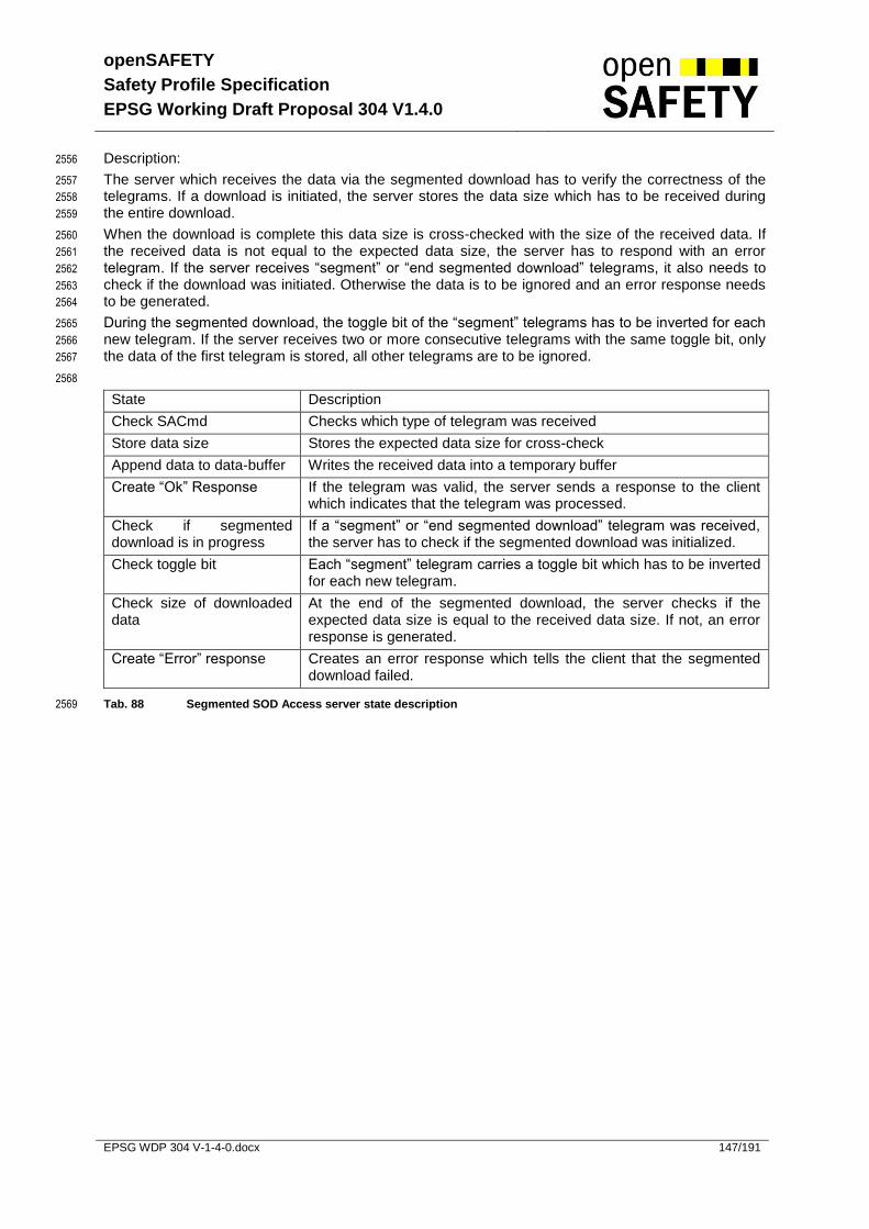
openSAFETY
Safety Profile Specification
EPSG Working Draft Proposal 304 V1.4.0
EPSG WDP 304 V-1-4-0.docx 147/191
Description: 2556
The server which receives the data via the segmented download has to verify the correctness of the 2557
telegrams. If a download is initiated, the server stores the data size which has to be received during 2558
the entire download. 2559
When the download is complete this data size is cross-checked with the size of the received data. If 2560
the received data is not equal to the expected data size, the server has to respond with an error 2561
telegram. If the server receives “segment” or “end segmented download” telegrams, it also needs to 2562
check if the download was initiated. Otherwise the data is to be ignored and an error response needs 2563
to be generated. 2564
During the segmented download, the toggle bit of the “segment” telegrams has to be inverted for each 2565
new telegram. If the server receives two or more consecutive telegrams with the same toggle bit, only 2566
the data of the first telegram is stored, all other telegrams are to be ignored. 2567
2568
State Description
Check SACmd Checks which type of telegram was received
Store data size Stores the expected data size for cross-check
Append data to data-buffer Writes the received data into a temporary buffer
Create “Ok” Response If the telegram was valid, the server sends a response to the client which indicates that the telegram was processed.
Check if segmented download is in progress
If a “segment” or “end segmented download” telegram was received, the server has to check if the segmented download was initialized.
Check toggle bit Each “segment” telegram carries a toggle bit which has to be inverted for each new telegram.
Check size of downloaded data
At the end of the segmented download, the server checks if the expected data size is equal to the received data size. If not, an error response is generated.
Create “Error” response Creates an error response which tells the client that the segmented download failed.
Tab. 88 Segmented SOD Access server state description 2569
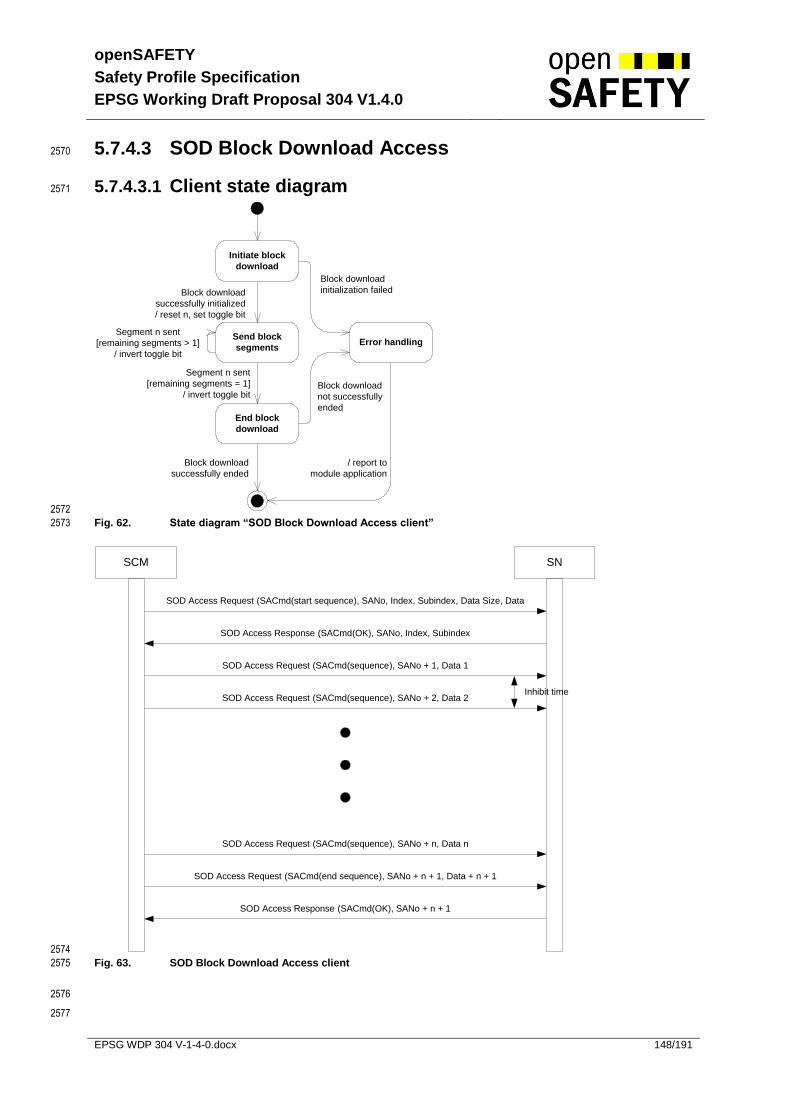
openSAFETY
Safety Profile Specification
EPSG Working Draft Proposal 304 V1.4.0
EPSG WDP 304 V-1-4-0.docx 148/191
5.7.4.3 SOD Block Download Access 2570
5.7.4.3.1 Client state diagram 2571
Initiate block
download
Error handlingSend block
segments
End block
download
Block download
successfully initialized
/ reset n, set toggle bit
Segment n sent
[remaining segments = 1]
/ invert toggle bit
Segment n sent
[remaining segments > 1]
/ invert toggle bit
Block download
initialization failed
Block download
not successfully
ended
Block download
successfully ended
/ report to
module application
2572
Fig. 62. State diagram “SOD Block Download Access client” 2573
SCM SN
SOD Access Request (SACmd(start sequence), SANo, Index, Subindex, Data Size, Data
SOD Access Response (SACmd(OK), SANo, Index, Subindex
SOD Access Request (SACmd(sequence), SANo + 1, Data 1
SOD Access Request (SACmd(sequence), SANo + 2, Data 2
SOD Access Request (SACmd(end sequence), SANo + n + 1, Data + n + 1
SOD Access Response (SACmd(OK), SANo + n + 1
SOD Access Request (SACmd(sequence), SANo + n, Data n
Inhibit time
2574
Fig. 63. SOD Block Download Access client 2575
2576
2577
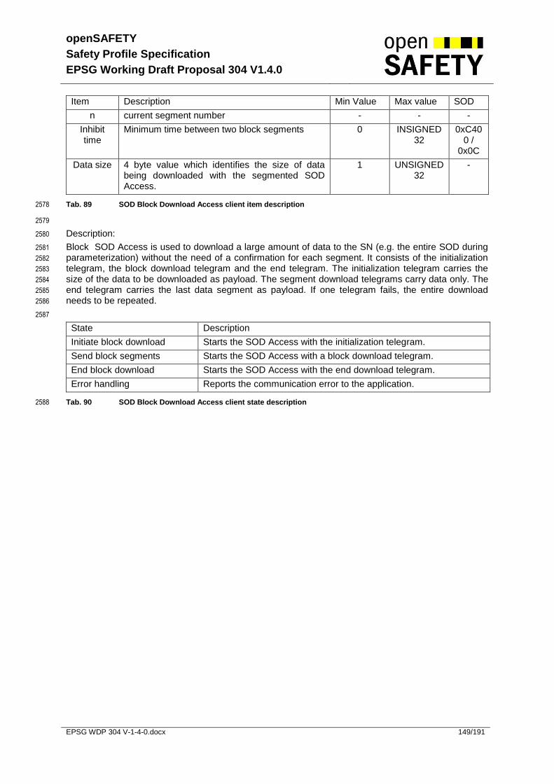
openSAFETY
Safety Profile Specification
EPSG Working Draft Proposal 304 V1.4.0
EPSG WDP 304 V-1-4-0.docx 149/191
Item Description Min Value Max value SOD
n current segment number - - -
Inhibit time
Minimum time between two block segments 0 INSIGNED32
0xC400 /
0x0C
Data size 4 byte value which identifies the size of data being downloaded with the segmented SOD Access.
1 UNSIGNED32
-
Tab. 89 SOD Block Download Access client item description 2578
2579
Description: 2580
Block SOD Access is used to download a large amount of data to the SN (e.g. the entire SOD during 2581
parameterization) without the need of a confirmation for each segment. It consists of the initialization 2582
telegram, the block download telegram and the end telegram. The initialization telegram carries the 2583
size of the data to be downloaded as payload. The segment download telegrams carry data only. The 2584
end telegram carries the last data segment as payload. If one telegram fails, the entire download 2585
needs to be repeated. 2586
2587
State Description
Initiate block download Starts the SOD Access with the initialization telegram.
Send block segments Starts the SOD Access with a block download telegram.
End block download Starts the SOD Access with the end download telegram.
Error handling Reports the communication error to the application.
Tab. 90 SOD Block Download Access client state description 2588

openSAFETY
Safety Profile Specification
EPSG Working Draft Proposal 304 V1.4.0
EPSG WDP 304 V-1-4-0.docx 150/191
5.7.4.3.2 Server state diagram 2589
Check SACmd
Check if block
download is in
progress
[block segment received]
Check toggle bit
Yes
Store data size
Append data to
buffer
Check if block
download is in
progress
Append data to
buffer
Check size of
downloaded
data
Append data to
buffer
Create „OK“
response for
end telegram
Create „OK“
response for
initiate telegram
Create „Error“
response
[toggle bit !=
internal toggle bit]
[initiate block download received]
/ start block download
/delete data buffer,
set internal toggle bit
[end block download received]
Yes
[received size ==
stored size]
[received size !=
stored size]
[toggle bit == internal toggle bit]
/ invert internal toggle bit
No
No
2590
2591
Fig. 64. State diagram “SOD Block Download Access Server” 2592
2593
Item Description Min Value Max value SOD
toggle bit The toggle bit is used to identify new segments. 0 1 -
data size 4 byte value which identifies the size of data being downloaded with the segmented SOD Access.
1 UNSIGNED32
-
size Size of the received data 0 UNSIGNED32
-
SACmd Safety Access Command - - -
Tab. 91 SOD Block Download Access server item description 2594
2595

openSAFETY
Safety Profile Specification
EPSG Working Draft Proposal 304 V1.4.0
EPSG WDP 304 V-1-4-0.docx 151/191
Description: 2596
The server which receives the data via the block download has to verify the correctness of the 2597
telegrams. If a download is initiated, the server stores the data size which has to be received during 2598
the entire download. 2599
When the download is complete this data size is cross-checked with the size of the received data. If 2600
the received data is not equal to the expected data size, the server has to respond with an error 2601
telegram. If the server receives “segment” or “end segmented download” telegrams, it also needs to 2602
check if the download was initiated. Otherwise the data is to be ignored and an error response needs 2603
to be generated. 2604
During the segmented download, the toggle bit of the “segment” telegrams has to be inverted for each 2605
new telegram. If the server receives two or more consecutive telegrams with the same toggle bit, only 2606
the data of the first telegram is stored, the other telegram is to be ignored. 2607
2608
State Description
Check SACmd Checks which type of telegram was received
Store data size Stores the expected data size for cross-check
Append data to data-buffer Writes the received data into a temporary buffer
Create “Ok” response for initiate telegram
If the telegram was valid, the server sends a response to the client which indicates that the telegram was processed.
Create “Ok” response for end telegram
If the telegram was valid, the server sends a response to the client which indicates that the telegram was processed.
Check if block download is in progress
If a “block” or “end block download” telegram was received, the server has to check if the block download was initialized.
Check toggle bit Each “block” telegram carries a toggle bit which has to be inverted for each new telegram.
Check size of downloaded data
At the end of the block download, the server checks if the expected data size is equal to the received data size. If not, an error response is generated.
Create “Error” response Creates an error response which tells the client that the block download failed.
Tab. 92 SOD Block Download Access server state description 2609
2610

openSAFETY
Safety Profile Specification
EPSG Working Draft Proposal 304 V1.4.0
EPSG WDP 304 V-1-4-0.docx 152/191
5.7.5 Safety Network Management Object (SNMT) 2611
5.7.5.1 SNMT Master 2612
2613
Fig. 65. State diagram “SNMT Master” 2614
Item Description Min Value
Max value SOD
n Max. count of retries 0 UNSIGNED8 Object index 1202h sub index 2h
(see 5.6.4.14)
Timeout of SNMT Response [CT]
1 UNSIGNED32 Object index 1202h sub index 1h
(see 5.6.4.14)
Tab. 93 SNMT master item description 2615
Description: 2616
The master sends an SNMT Request telegram to the slave. If a response is received or a response is 2617
not required, the client can continue (more SNMT telegrams, etc). If the response is timed out, the 2618
client retries to send the telegram n times. The number of retries as well as the timeout time for an 2619
SNMT Response telegram is to be set within the SOD of the client. 2620
2621
State Description
Send SNMT Request Sending the SNMT telegram to the slave
Wait for SNMT Response Waiting for the response from the server
SNMT Request Error Handling If the maximum number of retries was not reached the telegram will be sent again otherwise a communication error occurs.
Write diagnose data to SOD The diagnose data has to be available for the user. This is made through the SOD of the master.
Tab. 94 SNMT master state description 2622
Send SNMT
Request
Wait for SNMT Response
SNMT Request
Error Handling SNMT Response timeout
n retries not exceeded
SNMT Response
received
n retries exceeded
Write diagnose data to SOD

openSAFETY
Safety Profile Specification
EPSG Working Draft Proposal 304 V1.4.0
EPSG WDP 304 V-1-4-0.docx 153/191
5.7.5.2 SNMT Slave 2623
IDLE
Process SNMT
Request
[no response required][response required]
/ send SNMT response
SNMT Request
received
2624
Fig. 66. State diagram “SNMT Slave” 2625
Description: 2626
The slave receives an SNMT request telegram from the master. The telegram is processed according 2627
to the ID field. During processing, an SNMT Response may be generated and sent back to the master. 2628
2629
State Description
IDLE Wait for SNMT Request telegrams
Process SNMT Request Process the telegram according to the SNMT Request. Generate SNMT Response.
Tab. 95 SNMT slave state description 2630
2631

openSAFETY
Safety Profile Specification
EPSG Working Draft Proposal 304 V1.4.0
EPSG WDP 304 V-1-4-0.docx 154/191
5.7.6 SN Power Up 2632
2633
Fig. 67. State diagram “SN Power Up” 2634
Description: 2635
At power up, the SN starts the self initialization. An SN can contain a flash memory where all data is 2636
stored. This data is loaded during the self initialization. After which, the SN enters the Pre-Operational 2637
state. In this state the SN can get parameters from the SCM. The SN also sends cyclic messages to 2638
the SCM to inform the SCM about its status. When the SN switches from Pre-Operational to 2639
OPERATIONAL, it stores all parameters within the flash memory (optional). 2640
2641
State Description
Initialization Loading parameters from flash (optional)
Pre-Operational
Receiving parameters from SCM. UDID verification, etc. In this state all application data are set to the safe state (default of the object, see chapter 5.6.2).
Operational Sending and receiving SPDOs, time requests, etc
To keep the SN in operational it needs to receive a cyclic signal from the SCM. If the signal is timed out (timeout to be set within the SOD) the SN switches to Pre-Operational.
Tab. 96 SN power up state description 2642
5.7.6.1 States and Communication Object Relation 2643
The following table shows the relation between operational states and communication objects. 2644
Services on the listed communication objects may only be executed if the device is in the appropriate 2645
operational state. 2646
Initialization Pre-Operational Operational
SPDO X
SSDO X X
SNMT X X
Tab. 97 State and communication object relation 2647
Initialization
Pre-Operational
/ store parameters to flash (optional)
Operational
Life guarding timeout OR SNMT_SN_set_to_PRE_OP received

openSAFETY
Safety Profile Specification
EPSG Working Draft Proposal 304 V1.4.0
EPSG WDP 304 V-1-4-0.docx 155/191
5.7.6.2 Pre-Operational 2648
Pre-Operational
Wait for SADR
Check Parameter
Checksum and
Timestamp
[parameter checksum
and timestamp OK]
[parameter checksum and
timestamp not OK] / send
SNMT_SN_FAIL,
Error Group = Parameter,
Error Code = 0
Wait for
SNMT_SN_set_to_OP
Check other requirements
for operational state
[SNMT_Assign_SADR
received]
SNMT_SN_set_to_OP
received
[requirement not met] /
send SNMT_SN_FAIL,
Error Group = requirement
group,
Error Code = requirement
error code
[requirement met] / send
SNMT_SN_status_OP
Idle
[Main SADR
assigned] [Main SADR not
assigned]
[refresh time not
expired]
[(number of
Retries >=
max number
of retries) and
(max number
of retries !=
255)]
/number of retries = 0
[refresh time expired]
[(number of retries < max number of retries) or
(max number of retries == 255)]
/ send SNMT_SN_reset_guarding_SCM,
number of retries ++
Check Additional
Parameter
[parameter set not OK] / send
SNMT_SN_FAIL,
Error Group = Add. Parameter,
Error Code = Nr. Of Set & 0xF0
[add parameter OK]
2649
Fig. 68. State diagram “SN Pre-Operational” 2650
2651

openSAFETY
Safety Profile Specification
EPSG Working Draft Proposal 304 V1.4.0
EPSG WDP 304 V-1-4-0.docx 156/191
Item Description Min Value Max value SOD
Refresh time
Refresh time of SNMT_SN_reset_guarding_SCM signal [μs]
1 UNSIGNED32 Object index 100Dh
(see 5.6.4.6)
Max number
of retries
Maximum number of retries for the SNMT_SN_reset_guarding_SCM service
- UNSIGNED 8 Object index 100Eh
(see 5.6.4.7)
Tab. 98 SN Pre-Operational state item description 2652
2653
Description: 2654
When the SN enters the pre-operational state, the SNMT and SOD Access Rx services are started. In 2655
this state all application data are set to the safe state. The SNMT services are required for e.g. 2656
receiving UDID request telegrams. With SOD Access Commands, the SN can get new parameters 2657
from the SCM. Before being able to switch to operational, the SN at least has to receive its “Main 2658
SADR” and the “UDID of the SCM”. 2659
2660
State Description
Idle Receiving parameters from SCM. UDID verification. Etc.
Wait for SADR The SN waits to get its Main SADR from the SCM
Wait for SNMT_SN_set_to_OP The SN waits to be switched to Operating from the SCM.
Check Parameter Checksum and Timestamp
Checks if the parameter checksum as well as the parameter timestamp match the local settings. In case the checksum calculation takes a long time, the SN may reply to the SCM using the service SNMT_SN_busy. The SCM then has to send the service SNMT_SN_set_to_OP again.
Check Additonal Parameters Checks if the SN is needing additional parameters. If this is the case, an SN will respond to the SCM with an SNMT_SN_Fail and a corresponding error code. In case the check takes a long time, the SN may reply to the SCM using the service SNMT_SN_busy. The SCM then has to send the service SNMT_SN_set_to_OP again.
Check other requirements for Operational state
There might be several reasons for not being able to switch to operational state. Within this state the module firmware is requested if switching to operational is allowed, if not the reason is reported to the SCM.
Tab. 99 SN Pre-Operational state description 2661
2662

openSAFETY
Safety Profile Specification
EPSG Working Draft Proposal 304 V1.4.0
EPSG WDP 304 V-1-4-0.docx 157/191
5.7.6.3 Additional Parameters 2663
2664
During configuration, an SN is able to request additional parameter sets. Theses sets may then be 2665
transferred to the SN using a similar method thant the normal parameter download. 2666
2667
Check Additional Parameters
Parameters Are Verified
Are additional Parameters
needed?
[SNMT_SN_set_to_OP received]
Going operational
[No
Ad
ditio
na
l P
ara
me
ters
ne
ed
ed]
Check Timestamp & CRC
Send SN_FAIL
No
Request Header for
Parameter Set X
Request full parameter
set
[Full parameter set is valid]
[Timestamp & CRC are valid]
2668
Fig. 69. State diagram “Check Additional Parameters” 2669
Description: 2670
After the SCM and the SN have successfully verified the default parameter of the SN, the SCM will tell 2671
the SN to switch to operational using the signal SNMT_SN_set_to_OP. 2672
The SN is obligated to check, if he will need one or more additional parameter sets to allow switchitng 2673
to operational. If additional parameter sets are needed, the SN will respond to the command for going 2674
operational by sending an SN_FAIL with an error group regarding additional parameters, and the 2675
number of the expected parameter set as error code. The SCM will look up the corresponding set in 2676
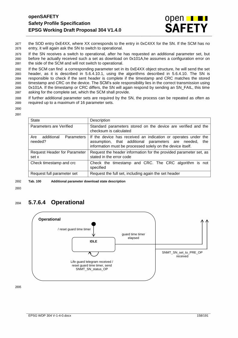
openSAFETY
Safety Profile Specification
EPSG Working Draft Proposal 304 V1.4.0
EPSG WDP 304 V-1-4-0.docx 158/191
the SOD entry 0xE4XX, where XX corresponds to the entry in 0xC4XX for the SN. If the SCM has no 2677
entry, it will again ask the SN to switch to operational. 2678
If the SN receives a switch to operational, after he has requested an additional parameter set, but 2679
before he actually received such a set as download on 0x101A,he assumes a configuration error on 2680
the side of the SCM and will not switch to operational. 2681
If the SCM can find a corresponding parameter set in its 0xE4XX object structure, he will send the set 2682
header, as it is described in 5.6.4.10.1, using the algorithms described in 5.6.4.10. The SN is 2683
responsible to check if the sent header is complete if the timestamp and CRC matches the stored 2684
timestamp and CRC on the device. The SCM’s sole responsibility lies in the correct transmission using 2685
0x101A. If the timestamp or CRC differs, the SN will again respond by sending an SN_FAIL, this time 2686
asking for the complete set, which the SCM shall provide. 2687
If further additional parameter sets are required by the SN, the process can be repeated as often as 2688
required up to a maximum of 16 parameter sets. 2689
2690
2691
State Description
Parameters are Verified Standard parameters stored on the device are verified and the checksum is calculated
Are additional Parameters needed?
If the device has received an indication or operates under the assumption, that additional parameters are needed, the information must be processed solely on the device itself.
Request Header for Parameter set x
Request the header information for the provided parameter set, as stated in the error code
Check timestamp and crc Check the timestamp and CRC. The CRC algorithm is not specified
Request full parameter set Request the full set, including again the set header
Tab. 100 Additional parameter download state description 2692
2693
5.7.6.4 Operational 2694
2695
Operational
/ reset guard time timer
IDLE
Life guard telegram received / reset guard time timer, send
SNMT_SN_status_OP
guard time timer elapsed
SNMT_SN_set_to_PRE_OP received

openSAFETY
Safety Profile Specification
EPSG Working Draft Proposal 304 V1.4.0
EPSG WDP 304 V-1-4-0.docx 159/191
Fig. 70. State diagram “SN Operational” 2696
2697
Fig. 71. Life guarding telegram 2698
Item Description Min Value Max value SOD
guard time timer - - Object index 100Ch sub index 1h and 2h
(see 5.6.4.4)
Tab. 101 SN Operational state item description 2699
Description: 2700
When the SN enters the Operational state, Life Guarding is started. The SN needs to receive cyclic 2701
telegrams from the SCM to remain in Operational state. If this telegram is timed out, the SN falls back 2702
into Pre-Operational state. 2703
State Description
IDLE Wait for Life Guarding telegram
Tab. 102 SN Operational state description 2704
5.7.7 SN Power Down 2705
All safe outputs return to safe state ( 0V ). 2706
5.7.8 SN Recovery after Restart / Error 2707
If an error occurred or the SN was restarted, the SN enters the Pre-Operational state. In this state, the 2708
SN sends a cyclic message (with no response) to the SCM. The SCM now can check the SN again, 2709
verify all parameters, UDID, DVI and then set the SN to Operational again. 2710
Safety Node
life guarding
life guarding
life guarding
life guarding
Non safe communi-cation layer Life guard telegram received, reset timeout
Data corrupted, ignore
Life guard timer elapsed, enter Pre-Operational state
SN in Pre-Operational, ignore
Life guard telegram received, reset timeout
Life guard telegram

openSAFETY
Safety Profile Specification
EPSG Working Draft Proposal 304 V1.4.0
EPSG WDP 304 V-1-4-0.docx 160/191
5.7.9 SCM Power Up 2711
2712
Fig. 72. State diagram “SCM Power Up” 2713
Description: 2714
After power-on, the SCM loads its parameters from a non-volatile memory. Then it switches to 2715
Operational. The Operational super-state is described later on. The SCM can be switched into the 2716
Stopped state using a SNMT service. In Stopped, the SCM does not manage any safety nodes. If 2717
safety nodes are being configured with an external tool, the SCM must be in state Stopped. 2718
State Description
Initialization The SCM loads its parameters from a non-volatile memory.
Operational In Operational state all safety nodes are configured and started.
Stopped The SCM waits for the signal to switch back to Operational.
Tab. 103 SCM power up state description 2719
5.7.9.1 States and Communication Object Relation 2720
The following table shows the relationship between operational states and communication objects. 2721
Services on the listed communication objects may only be executed if the device is in the appropriate 2722
operational state. 2723
2724
Initialization Stopped Operational
SSDO X X
Tab. 104 State and communication object relation 2725
Initialization
Operational Stopped
SNMT_SCM_set_to_STOP received
SNMT_SCM_set_to_OP received
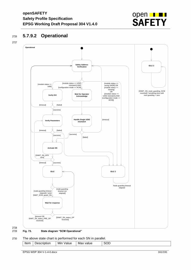
openSAFETY
Safety Profile Specification
EPSG Working Draft Proposal 304 V1.4.0
EPSG WDP 304 V-1-4-0.docx 161/191
5.7.9.2 Operational 2726
2727
Operational
Safety Address
Verification
[module status ==
valid]
[module status ==
wrong SADR] OR
[module status ==
missing]
OR
([module status ==
UDID mismatch] AND
[configuration mode ==
MCM])
[module status == UDID
mismatch] AND
[configuration mode == ACM]
Verify DVIWait for Operator
Acknowledge
Handle Single UDID
mismatch[timeout]
[timeout] [failed]
[success]
Verify Parameters
[timeout] [failed]
[success]
Activate SN
[failed]
[success]
[timeout] [success]
IDLE 2
Node guarding timeout
elapsed
IDLE
Wait for response
[node guarding
timeout not
elapsed]
[node guarding timeout
elapsed] / send
SNMT_SCM_guard_SN
[SNMT_SN_status_OP
received]
[timeout OR
SNMT_SN_status_PRE_OP
received]
IDLE 3
[SNMT_SN_reset_guarding_SCM
received] / remaining time until
next guarding = zero
[SNMT_SN_ACK
sent]
2728
Fig. 73. State diagram “SCM Operational” 2729
The above state chart is performed for each SN in parallel. 2730
Item Description Min Value Max value SOD

openSAFETY
Safety Profile Specification
EPSG Working Draft Proposal 304 V1.4.0
EPSG WDP 304 V-1-4-0.docx 162/191
Guarding Timeout
1 UNSIGNED32 Object index 100Ch sub index 1h
(see 5.6.4.4)
Tab. 105 SCM operational state item description 2731
2732
Description: 2733
When the SCM switches to Operational, it starts the UDID/SADR verification of all configured nodes. If 2734
an UDID mismatch was detected this is handled separately. The parameters for all valid nodes will be 2735
verified against the list of CRCs and Timestamps within the SOD (Object 0xC400-0xC7FE). If a node 2736
is valid (correct UDID, SADR and DVI) and its parameters are also valid, it will be set to operational. 2737
Operational nodes get a cyclic message to keep them in Operational state. 2738
2739
State Description
Safety Address Verification The SCM verifies the UDID of the node. Also the correct SADR will be assigned to the node.
Verify DVI The DVI has to be checked to ensure that the new node meets the technical requirements.
Verify Parameters Parameter check and eventually re-parameterization of the SN.
Activate SN After successful parameterization, the SCM switches the SN to Operational.
IDLE Waits until next SNMT_SCM_guard _SN needs to be sent.
Wait for response Waits for the response of the SNMT_SCM_guard_SN service.
Wait for Operator Acknowledge
If an unknown UDID was detected during start-up or operation, an operator-acknowledge is needed to accept and verify the new node. This state is only entered in Automatic Configuration Mode (ACM).
Handle Single UDID Mismatch If a new SN was detected (replacement, commissioning, etc) it is verified and checked to see if it meets the requirements or not.
IDLE 2 If the node is not present, or does not meet the technical requirements (module was replaced with a wrong type), the node will not be handled for a node guarding interval. This ensures, that nodes, which are not present or nodes which were replaced with a different module type will get handled again, but do not produce too much bus activity.
IDLE 3 Sets the remaining time until the next node guarding to zero in case a SNMT_SN_reset_guarding_SCM telegram is received. After a power up of a module, the module sends this type of telegram to the SCM. This ensures, that the SCM recognizes (by the response to the guarding telegram) that the module is down and needs to be restarted.
Tab. 106 SCM operational state description 2740
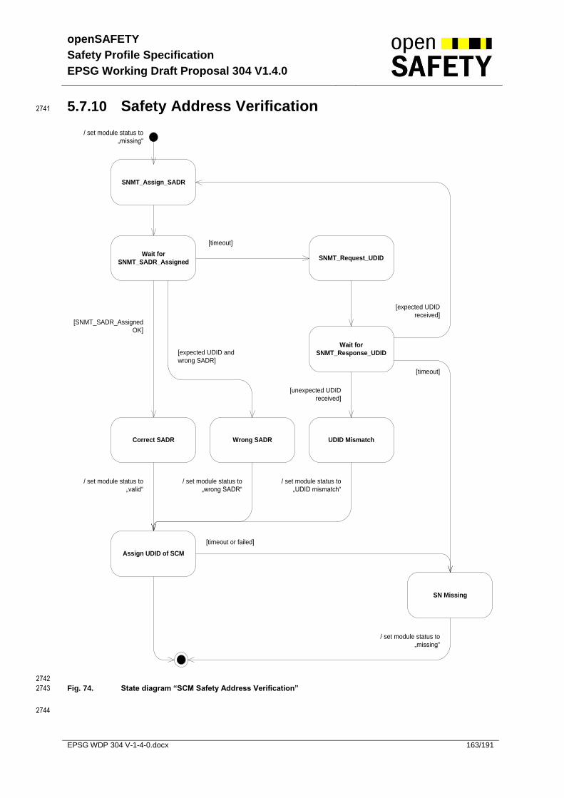
openSAFETY
Safety Profile Specification
EPSG Working Draft Proposal 304 V1.4.0
EPSG WDP 304 V-1-4-0.docx 163/191
5.7.10 Safety Address Verification 2741
SNMT_Assign_SADR
Wait for
SNMT_SADR_Assigned
/ set module status to
„missing“
Correct SADR
/ set module status to
„valid“
[SNMT_SADR_Assigned
OK]
Wrong SADR
[expected UDID and
wrong SADR]
SNMT_Request_UDID
[timeout]
Wait for
SNMT_Response_UDID
UDID Mismatch
SN Missing
[timeout]
[unexpected UDID
received]
[expected UDID
received]
/ set module status to
„UDID mismatch“
/ set module status to
„missing“
/ set module status to
„wrong SADR“
Assign UDID of SCM
[timeout or failed]
2742
Fig. 74. State diagram “SCM Safety Address Verification” 2743
2744
openSAFETY
Safety Profile Specification
EPSG Working Draft Proposal 304 V1.4.0
EPSG WDP 304 V-1-4-0.docx 164/191
Item SOD
module status
Object index C400h – C7FEh sub index 5h
(see 5.6.4.20)
expected UDID Object index CC01h – CFFFh (corresponding to assigned SADR) -> sub index 1 – 254d
(see 5.6.4.22)
assigned SADR Object indeces CC01h – CFFFh
(see 5.6.4.22)
Tab. 107 Safety address verification item description 2745
Description: 2746
The Safety Address Verification is used to verify the correctness of the safety network. All module 2747
changes are detected due to the uniqueness of the UDID. The object indeces CC01h-CFFFh 2748
correspond to the possible safety addresses 1d – 1023d. 2749
This State Machine is independent from the chosen configuration mode (ACM or MCM). 2750
2751
State Description
SNMT_Assign_SADR Assigns the SADR to a configured node.
wait for SNMT_SADR_Assigned
The response contains the actual SADR. Some nodes might not be able to change the SADR because it is to be set using hardware switches.
SNMT_Request_UDID Requests the UDID of a configured node.
wait for SNMT_Response_UDID
The response from the node contains its UDID.
Correct SADR The SADR could be assigned. The node is valid.
Wrong SADR The UDID is known but the SADR could not be assigned. The node is invalid.
UDID Mismatch The node does not have the expected UDID. An operator-acknowledge is needed to accept and start the node.
SN missing The configured SN could not be reached. The node might be defective or not in the network. The node is missing.
Assign UDID of SCM Send UDID of SCM to sn via the corresponding service.
Tab. 108 Safety address verification state description 2752
5.7.11 Commissioning Mode 2753
There is no special commissioning mode. The first time the SCM is started, all nodes are handled as 2754
nodes with a UDID mismatch. 2755

openSAFETY
Safety Profile Specification
EPSG Working Draft Proposal 304 V1.4.0
EPSG WDP 304 V-1-4-0.docx 165/191
5.7.12 Handle Single UDID Mismatch 2756
Handle Single UDID Mismatch
Write 0 to UDID List in SOD
SNMT_Assign_SADR
Verify DVI
Verify Parameters
Verify uniqueness of UDID
Store memorized UDID on
SCM
OK / memorize
returned UDID
OK
OK
OK
/ handle single
UDID
mismatch =
success
SN missing Wrong or defect SN
False / set
module status to
„wrong SADR“
False / set
module status to
„invalid“
False / set
module status to
„invalid“
False / set
module status to
„wrong
parameters“
timeout
timeout
timeout
/ handle single
UDID
mismatch =
failed
/ handle single UDID
mismatch = timeout,
set module status to
missing
2757
Fig. 75. State diagram “SCM Handle Single UDID Mismatch” 2758
Description: 2759
Handles all nodes which have UDID mismatch. If the new node meets the requirements (DVI, 2760
assignment of SADR, etc) no re-configuration of the SCM is needed when replacing nodes. 2761
2762

openSAFETY
Safety Profile Specification
EPSG Working Draft Proposal 304 V1.4.0
EPSG WDP 304 V-1-4-0.docx 166/191
2763
State Description
Write 0 to UDID list in SOD
The SCM deletes the “old” stored UDID in the SOD (Object 0xCC01-0xCFFF). 0 is no valid UDID.
SNMT_Assign_SADR The SCM writes the configured SADR to the module.
Verify DVI The DVI has to be checked to ensure that the new node meets the technical requirements.
Verify Parameters The parameters which are stored on the node are cross checked with the parameters stored on the SCM. The node will get new parameters if necessary/possible.
Verify uniqueness of the UDID
The responded UDID is checked against the UDID list within the SOD (Object 0xC001-0xCFFF)
Store UDID on SCM The new UDID is stored on the SCM to be able to recognize the node at the next start-up.
SN missing The SN did not answer one or more telegrams from the SCM. Therefore the SN will be handled like a missing node.
Wrong or defect SN The node does not meet the technical requirements specified in the SCM.
possible reasons are:
The DVI does not meet the requirements
It is not possible to change the SADR of the device (this can happen if the SADR is to be set with hardware switches)
The parameters stored on the node are not equal to the parameters stored on the SCM but a download is not possible (this can happen if the SCM does not hold the parameters for a node and only knows the required checksum)
The UDID is not unique within the SDN (this normally should never happen because the UDID is designed to be globally unique)
Tab. 109 Handle UDID mismatch state description 2764
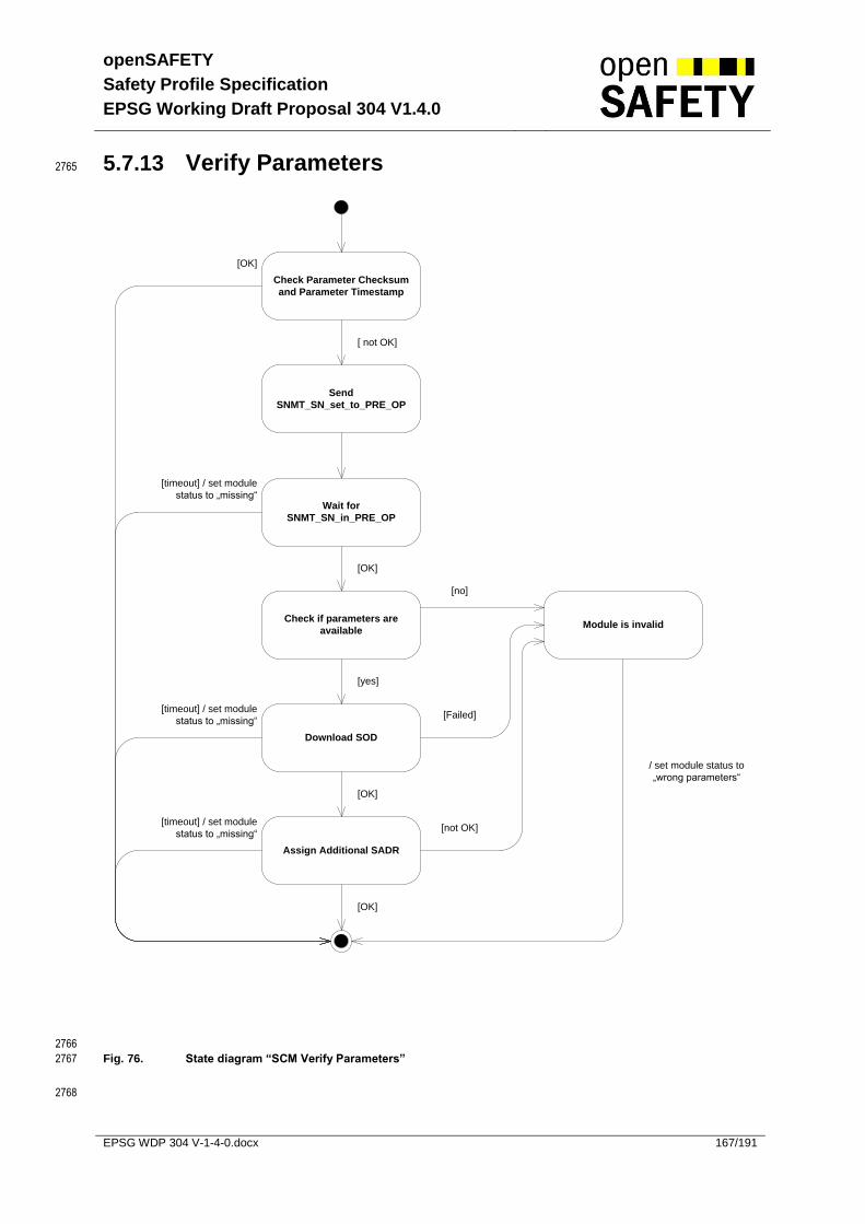
openSAFETY
Safety Profile Specification
EPSG Working Draft Proposal 304 V1.4.0
EPSG WDP 304 V-1-4-0.docx 167/191
5.7.13 Verify Parameters 2765
Check Parameter Checksum
and Parameter Timestamp
Send
SNMT_SN_set_to_PRE_OP
[yes]
[timeout] / set module
status to „missing“Wait for
SNMT_SN_in_PRE_OP
Check if parameters are
available
[OK]
[ not OK]
[OK]
Download SOD
Module is invalid
/ set module status to
„wrong parameters“
[no]
Assign Additional SADR
[timeout] / set module
status to „missing“
[timeout] / set module
status to „missing“
[OK]
[OK]
[Failed]
[not OK]
2766
Fig. 76. State diagram “SCM Verify Parameters” 2767
2768
openSAFETY
Safety Profile Specification
EPSG Working Draft Proposal 304 V1.4.0
EPSG WDP 304 V-1-4-0.docx 168/191
2769
Description: 2770
The parameters (SOD) stored on the SN are compared with the parameters stored on the SCM. 2771
Attention: It is not absolutely necessary to store all parameters for all nodes on the SCM. It is also 2772
possible to only store the required parameter checksum on the SCM. In this case, the SCM can verify 2773
the correctness of the parameters on the node. If the parameters are not correct the SCM will NOT be 2774
able to re-configure such nodes. 2775
State Description
Check Parameter Checksum and Parameter Timestamp
The SCM checks if the current parameters for the node are the same which are stored on the SCM.
Send SNMT_SN_set_to_PRE_OP
Resets the SN.
wait for SNMT_SN_in_PRE_OP
Waits for the reply of the reset service.
Check if parameters are available
If the checksum on the node is different from the checksum on the SCM, the SCM checks if parameters for re-configuration of the node are available.
Download SOD The SCM re-configures the node.
Module is invalid If the parameters on the node are not equal to the parameters stored on the SCM and re-configuration of the module is not possible, the module is invalid and may not be set to Operational.
Assign additional SADRs The SCM assigns the SADR for the optional TxSPDOs 2-1023 of the corresponding SN.
Tab. 110 Parameter verification state description 2776

openSAFETY
Safety Profile Specification
EPSG Working Draft Proposal 304 V1.4.0
EPSG WDP 304 V-1-4-0.docx 169/191
5.7.14 Handle SN Version 2777
Ask for 0x1018 version entry
SCM operates with same
version
SCM will use own version
[Version received]
[Re
ce
ive
d S
SD
O A
bo
rt]
[OK]
Assume SN uses Version 1.3SCM marks SN as
„incompatible version“
[Not OK]
Module will not be set to
operational
2778
Fig. 77. State diagram “Handle SN version” 2779
Description: 2780
The version for each SN is stored in its device vendor information object 0x1018 (see 5.6.4.8). During 2781
power-up, the SCM will verify the version of the node. If the version responds with the correct version, 2782
or a version the SCM is compatible with, the SCM will use the provided version as the version of the 2783
SN. If the SCM is not compatible with such a version, he must stop the boot-up of the device, and 2784
recycle the boot-up sequence for this device. In any other case, the SCM will use version 1.3 as 2785
default and will disable any features introduced beyond that version. 2786
2787
If the version provided by the module is incompatible with the operating SCM, the SCM will set the 2788
module state to “incompatible version” and the SN will not be set to operational. 2789
2790
The SN must allways assume that the SCM will be using the version provided by the SN. 2791
2792
2793

openSAFETY
Safety Profile Specification
EPSG Working Draft Proposal 304 V1.4.0
EPSG WDP 304 V-1-4-0.docx 170/191
2794
State Description
Ask for 0x1018 version entry
The SOD entry for the openSAFETY stack version is retrieved from the module
SCM operates with same version
SCM uses the same version as provided by the SN
Assume SN uses version 1.3
SCM will operate under the assumption, that the SN is using version 1.3
SCM marks SN as “incompatible version”
SCM will set the module state “incompatible version” and the SN will not be set to operational
SCM will use own version SCM will operate under the assumption, that his version is the same as the version of the SN.
Tab. 111 Version verification state description 2795
2796
2797

openSAFETY
Safety Profile Specification
EPSG Working Draft Proposal 304 V1.4.0
EPSG WDP 304 V-1-4-0.docx 171/191
5.7.15 Activate SN 2798
Activate SN
Wait for response
[SNMT_status_OP
received] / „Activate
SN“ = success
[SNMT_SN_FAIL
received]
Report to application
timeout / „Activate SN“
= timeout
Insert Error Group and
Error Code Information into
SNMT_SN_ACK
Wait for application
Acknowledge
/ send SNMT_SN_ACK
Send
SNMT_SN_put_to_OP
[SNMT_SN_calc_CRC
received]
2799
2800
Fig. 78. State diagram “Activate SN“ 2801
Description : 2802
The SCM tries to set the SN to Operational. The SN ether ca switch to Operational or there is an error 2803
occurring during switching to Operational. This error is reported with the SNMT_SN_FAIL telegram. 2804
The SCM receives this telegram and reports it to the application. The vendor specific application has 2805
to decide how to cope with the situation. It can send an acknowledgement telegram SNMT_SN_ACK if 2806
the error can get acknowledged, or keep the SN in Pre-Operational if the problem cannot be solved. 2807
2808
State Description
Wait for response The SCM waits for the response from the SN
Report to application In case of an error the error is reported to the application
Wait for application Acknowledge
The application may set the error group and the error code information for the acknowledgement of the error.
Tab. 112 SN activation state description. 2809
openSAFETY
Safety Profile Specification
EPSG Working Draft Proposal 304 V1.4.0
EPSG WDP 304 V-1-4-0.docx 172/191
5.7.16 Module Exchange 2810
Exchanged modules will send the SNMT_SN_in_PRE_OP message to the SCM. The SCM will handle 2811
those exchanged nodes as UDID-mismatch nodes. After operator acknowledge, they will be 2812
programmed and set to OPERATIONAL. 2813

openSAFETY
Safety Profile Specification
EPSG Working Draft Proposal 304 V1.4.0
EPSG WDP 304 V-1-4-0.docx 173/191
6 Parameterization Interface of SOD 2814
The parameterization of any openSAFETY devices has to be done using a software tool which was 2815
developed and certified according to IEC 61508. Such a software tool always has to be part of a 2816
complete safety related automation system. 2817
2818
The software tool will transfer a valid SOD configuration to the openSAFETY device by defined 2819
openSAFETY services. Direct vendor specific access to the device is not supported. 2820
6.1 Configuration of an SD 2821
A single openSAFETY safety domain is configured by defining the SOD for an SCM. A software tool 2822
will create a valid SOD configuration for such an SCM, containing every parameter and setting for 2823
each participant of this SD. This configuration must be provided to the SCM in a secure way and prior 2824
to the power-up of the network. 2825
2826
During the power-up, the SCM will query each individual SN within the SD and guarantees, that the 2827
correct and valid configuration is being stored on each individual device. 2828
2829
The SCM will hold a parameter set for each SN within the SD. The parameter set contains 2830
2831
Communication and timing parameters 2832
SPDO communication parameters 2833
SPDO mapping information 2834
Device specific parameters 2835
Channel mapping configuration 2836
2837
Additionally the timestamp and the checksum of the parameter configuration will be transmitted during 2838
power-up, enabling each device individually to verify, if the transmitted parameter set is valid. 2839
2840
If the device supports additional parameter sets, these have to be stored on the SCM before power-up 2841
as well, and will be transported using openSAFETY services, as they are needed by the SN. 2842
2843
Only if all parameters are verified, and every device within a SD has verified, that it’s configuration is 2844
valid and transferred successfully, the SD is fully configured and may enter the operational phase. 2845
2846
Parameters which where left at their default state, can be omitted from the configuration send to the 2847
SN, and the SN must assume the default value is used for such entries. 2848
6.2 Parameter check mechanism 2849
The parameters within the SOD are secured by calculcating a CRC checksum for the SOD entries. 2850
For each 4k bit block of SOD data, a 32bit checksum will be calculated and is stored in the DVI object 2851
entry of the SOD, see 5.6.4.8. 2852
2853
An SCM may either upload only the parameter timestamp from an SN or the timestamp together with 2854
the stored CRCs, and depending on this information decide, if a reconfiguration of the SN is necessary 2855
or not. 2856

openSAFETY
Safety Profile Specification
EPSG Working Draft Proposal 304 V1.4.0
EPSG WDP 304 V-1-4-0.docx 174/191
7 openSAFETY Conformance 2857
The Conformance test is one part of the safety life cycle model for an openSAFETY device. Each 2858
node which is within an interoperable openSAFETY communication network has to provide 2859
compatibility according to this document. Only the compatibility of devices guarantees the availability 2860
and safety of openSAFETY networks. 2861
7.1 openSAFETY Change Management 2862
2863
Working group
openSAFETY
Specification
Notified Body
Approval
Lock on
Specification by
EPSG
Task group for
modification
Development of
Assessment
specification
Lock on
Specification by
EPSG
Task group for
modification
Notified Body
Approval
changes if necssary
2864
Fig. 79. Change Management Flow of Specification 2865
Change management is a very important point in the openSAFETY life cycle model. Each change 2866
within the specification must be validated and verified by a notified body (e.g. TUV). The EPSG must 2867
manage all further steps for certification. If the content of openSAFETY specification is modified, it 2868
must be checked to see what kind of modification is necessary for the test specification. In each case, 2869
the test specification is a derived from the openSAFETY Specification. Test specification and the test-2870
tools must also be approved by a notified body. 2871

openSAFETY
Safety Profile Specification
EPSG Working Draft Proposal 304 V1.4.0
EPSG WDP 304 V-1-4-0.docx 175/191
7.2 Certification flow for openSAFETY devices 2872
Conformance test flow for EPLsafety devices
Certfification for
underlying Fieldbus
openSAFETY
Conformance test
openSAFETY
Conformance
Approval
Approval of Functional
Safety by Notified
Body
2873
Fig. 80. Certification flow of openSAFETY devices – e.g. on POWERLINK 2874
Network protocol Certification 2875
For openSAFETY certification, the underlying communication layer for all non safe communications is 2876
required. For successful interactions between different safety nodes, all mandatory network services 2877
must be implemented conforming to the relevant standard. 2878
2879
openSAFETY Conformance test 2880
The openSAFETY Conformance-test must ensure that an openSAFETY device conforms to all safety 2881
services and measurements according to the openSAFETY Profile Specification. The test should be 2882
done by an independent body or by a certified test tool. The result must be a certificate and a detailed 2883
test report which is needed for obtaining the Functional Safety Certification of a notified body. 2884
2885
Approval of Functional Safety by Notified Body 2886
If machinery needs official approval (e.g. for IEC 61508 or other safety related standards), all 2887
openSAFETY devices being used need this approval too. According to the Standards, Functional 2888
Safety has to be certified by a notified body. 2889
2890
After all three certifications, the devices can be marked with the openSAFETY Logo. 2891
2892
Fig. 81. openSAFETY Logo 2893

openSAFETY
Safety Profile Specification
EPSG Working Draft Proposal 304 V1.4.0
EPSG WDP 304 V-1-4-0.docx 176/191
8 Safety Requirement Specification 2894
8.1 CRC error detection capabilities 2895
openSAFETY uses the following CRC polynomials as additional measure to protect information 2896
against data corruption. According [3] respectively [6] all these CRC polynomials are well known and 2897
guarantee the following error detection capabilities: 2898
2899
CRC Polynomial
Koopmann notation
error detection capabilities
number of bits (CRC not included)
Properness Used for
12Fhex 0x97 [3]
HD 4 up to 119 bits Yes up to 119 bits [7]
Frames up to 8 byte payload data (up to 104 bits data area)
15935hex 0xAC9A [3]
HD 5 up to 241 bits HD 2 up to 2048 bits
- Frames for SLIM SSDO Services only, from 9 up to 240 byte payload data (up to 1960 bits data area)
1755Bhex 0xBAAD [3]
HD 4 up to 2048 bits Yes up to 2048 bits [7]
Frames except SLIM SSDO Services, from 9 up to 240 byte payload data (up to 1960 bits data area)
11EDC6F41hex 0x8F6E37A0 [6]
HD 8 up to 128 bits HD 6 up to 4K bits HD 4 up to 64K bits
- Parameter data up to 4K bits per block
Tab. 113 CRC Polynomials and characteristic 2900
8.2 Failure detection for parameterization services 2901
The safety layer provides a block CRC to detect systematic and stochastic corruption of parameter 2902
and configuration data. All principles are according to international standards [2]. The chosen measure 2903
(CRC 11EDC6F41hex) guaranties an error detection capability for parameter and configuration data of 2904
at least HD 6 and is therefore a proper measure against stochastic errors during transmission of data. 2905
2906
To detect systematic failures, parameter and configuration data are secured with a timestamp and will 2907
be checked against predefined values by the SCM. 2908
8.3 Failure detection for data transfer services 2909
The safety layer contains measures for detection of systematic and stochastic errors. All principles are 2910
according to international standards [1], [2]. The mathematical background for the calculation of the 2911
stochastic residual error probability is shown in detail in the following chapters. 2912

openSAFETY
Safety Profile Specification
EPSG Working Draft Proposal 304 V1.4.0
EPSG WDP 304 V-1-4-0.docx 177/191
8.3.1 Systematic failures 2913
The safety related data frame contains a 2-byte-information of the real time (time stamp). In addition to 2914
the address-information and the use of a watchdog, which detects any missing frames that occur 2915
during the reaction time, all systematic failures will be detected: 2916
By the combined use of the timing information (time stamp) and the internal watchdog, a loss and an 2917
insertion of data will be also detected because only one message will be accepted within a certain 2918
time frame. If no valid information appears during a time frame, a loss of data is assumed. 2919
2920
The following table gives an overview for the failures and the measures used: 2921
Consecutive
Num
ber
Tim
e M
ark
Tim
e E
xpecta
tio
n
Echo
Identifier
Data
Pro
tection
Redu
nda
ncy w
ith
Cro
ss C
heck
Diffe
rent
measure
s
for
sta
nd
ard
and
safe
fra
mes
Repetition X
Loss X
Insertion X
Incorrect Sequence X
Delay X X
Incorrect Data X X
Coupling of standard and safe frames X
Tab. 114 openSAFETY failure measures 2922
The table shows the measures which have been chosen by openSAFETY. The specific function of the 2923
time stamp combined with a watchdog also allows detecting a loss and an insertion of data. 2924
8.3.2 Stochastic errors 2925
To verify the correctness of data and to enable the receiving device to identify any stochastic error, the 2926
following principles will be used: 2927
2928
CRC-calculation 2929
Comparison of data-information of both sub frames 2930
Checking of time stamp 2931
Checking of received address (comparison with internal address or address in look-up-table) 2932
2933
The checking of time stamp has already been described. 2934
2935
The safety frame consists of 2 sub frames. Each sub frame contains a CRC, which will detect all 2936
possible errors up to the given Hamming Distance. The payload data and the address information 2937
from sub frame 1 are repeated in sub frame 2. The signatures of CRC1 and CRC2 are different even if 2938
the polynomials for determining CRC1 and CRC2 are identical, because the residual is calculated with 2939
a different number of bytes from both sub frames. The polynomial guarantees a Hamming Distance of 2940
at least 4 for both sub frames. 2941
2942
The following figure and table shows the structure of the entire safety frame and gives an overview of 2943
the Frame elements and the applied measures against stochastic errors 2944

openSAFETY
Safety Profile Specification
EPSG Working Draft Proposal 304 V1.4.0
EPSG WDP 304 V-1-4-0.docx 178/191
2945
Fig. 82. Structure of POWERLINK safety frame 2946
2947
Field Length [bit]
Checked
by
CR
C
Duplic
ate
d
Expectation
Comment
ADR 10 yes yes
ID 2 yes yes Corruption of identifier but the resulting identifier is still an SPDO identifier, these errors are not detected
ID 4 yes yes yes Corruption of identifier but the resulting identifier is no longer an SPDO identifier, these errors are detected
LE 8 yes yes Corruption of the Length Field will cause the consumer to interpret wrong data as a CRC, the start address of the second sub frame will be wrong, …
CT(L) 8 yes
CT(M) 8 yes yes Corruption of the major counter will cause the consumer to detect a time synchronization problem
TADR 10 yes yes Corruption of the Time Address will cause the consumer to detect a time synchronization problem
TR 6 yes yes Corruption of the Time Identifier will cause the consumer to detect a time synchronization problem
CRC 8 / 16
DB (0 – 240) * 8 yes yes
DB + 16 Sum of duplicated bits
12 Sum of bits with data expectation within sub frame 1
28 Sum of bits with data expectation within sub frame 2
Tab. 115 Overview of Frame elements and applied measures against stochastic errors 2948
8.3.2.1 Calculation of residual error probability 2949
For the calculation of the residual error probability of openSAFETY, the following symbols are used: 2950
2951
symbol Description
BER bit error rate of the communication channel
Nx Length of sub frame N1 … length of sub frame 1 N2 … length of sub frame 2
D Number of duplicated bits
R Length of the used CRC-polynomial
C number of bits of the payload data

openSAFETY
Safety Profile Specification
EPSG Working Draft Proposal 304 V1.4.0
EPSG WDP 304 V-1-4-0.docx 179/191
Mx Number of bits with expectation
M1 … number of bits within sub frame 1 M2 … number of bits within sub frame 2
d Hamming distance
Tab. 116 Residual error probability calculation, symbols and terms 2952
2953
The calculation of the residual error probability of openSAFETY is now shown step by step: 2954
2955
(a) According [1], the probability of “e” corrupted bits within a sub frame is: 2956
)1()1(1
)(1 eNe BERBERe
NeR
)2()1(2
)(2 eNe BERBERe
NeR
2957
e number of corrupted bits 2958
Equation 2. Binomial distribution, probability for “e” corrupted bits within a sub frame 2959
2960
(b) According [7], the probability of “e” corrupted bits with “i” corruptions within the duplicated bits is 2961
given by the hyper-geometric distribution: 2962
e
N
ie
DN
i
D
ieBa1
1
),(1
e
N
ie
DN
i
D
ieBa2
2
),(2
2963
e number of corrupted bits 2964 i number of corrupted bits within duplicated bits 2965
Equation 3. Hyper-geometric distribution 2966
2967
(c) According [7], the probability of identical corrupted bits within sub frame 1 and sub frame 2 is: 2968
1
)(
i
DiBb
2969
i number of corrupted bits within duplicated bits 2970
Equation 4. Reduction of residual error probability by duplication of data 2971
2972
(d) According [7], all used CRC polynomials are known as proper polynomials. Since them, an 2973
additional reduction of the residual error probability is defined as: 2974
)1(2)( ReBc for Koopman 0x97 if e is even 2975
0)( eBc for Koopman 0x97 if e is odd 2976
ReBc 2)( for Koopman 0xBAAD 2977
e number of corrupted bits 2978
Equation 5. Reduction of residual error probability by proper polynomials 2979
2980
(e) According [7], the reduction of the residual error probability by the data expectation is: 2981
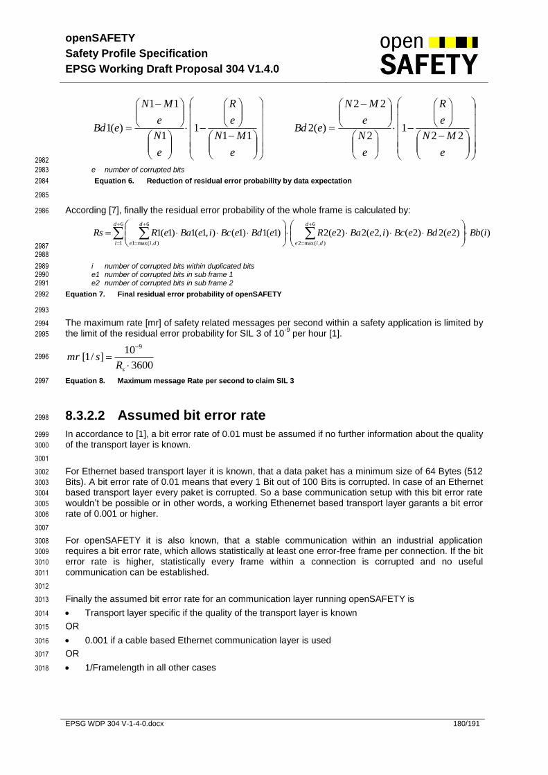
openSAFETY
Safety Profile Specification
EPSG Working Draft Proposal 304 V1.4.0
EPSG WDP 304 V-1-4-0.docx 180/191
e
MN
e
R
e
N
e
MN
eBd11
11
11
)(1
e
MN
e
R
e
N
e
MN
eBd22
12
22
)(2
2982
e number of corrupted bits 2983
Equation 6. Reduction of residual error probability by data expectation 2984
2985
According [7], finally the residual error probability of the whole frame is calculated by: 2986
)()2(2)2(),2(2)2(2)1(1)1(),1(1)1(16
),max(2
6
1
6
),max(1
iBbeBdeBcieBaeReBdeBcieBaeRRsd
die
d
i
d
die
2987
2988
i number of corrupted bits within duplicated bits 2989 e1 number of corrupted bits in sub frame 1 2990 e2 number of corrupted bits in sub frame 2 2991
Equation 7. Final residual error probability of openSAFETY 2992
2993
The maximum rate [mr] of safety related messages per second within a safety application is limited by 2994
the limit of the residual error probability for SIL 3 of 10-9
per hour [1]. 2995
3600
10]/1[
9
sRsmr
2996
Equation 8. Maximum message Rate per second to claim SIL 3 2997
8.3.2.2 Assumed bit error rate 2998
In accordance to [1], a bit error rate of 0.01 must be assumed if no further information about the quality 2999
of the transport layer is known. 3000
3001
For Ethernet based transport layer it is known, that a data paket has a minimum size of 64 Bytes (512 3002
Bits). A bit error rate of 0.01 means that every 1 Bit out of 100 Bits is corrupted. In case of an Ethernet 3003
based transport layer every paket is corrupted. So a base communication setup with this bit error rate 3004
wouldn’t be possible or in other words, a working Ethenernet based transport layer garants a bit error 3005
rate of 0.001 or higher. 3006
3007
For openSAFETY it is also known, that a stable communication within an industrial application 3008
requires a bit error rate, which allows statistically at least one error-free frame per connection. If the bit 3009
error rate is higher, statistically every frame within a connection is corrupted and no useful 3010
communication can be established. 3011
3012
Finally the assumed bit error rate for an communication layer running openSAFETY is 3013
Transport layer specific if the quality of the transport layer is known 3014
OR 3015
0.001 if a cable based Ethernet communication layer is used 3016
OR 3017
1/Framelength in all other cases 3018

openSAFETY
Safety Profile Specification
EPSG Working Draft Proposal 304 V1.4.0
EPSG WDP 304 V-1-4-0.docx 181/191
8.3.2.3 Residual error probability 3019
The following table show the residual error probability for openSAFETY and the maximum message 3020
rate per second to claim SIL 3. 3021
3022
Payload [Bytes] BER = 1/Framelength BER=0.001
Rs mrSIL3[1/s] Rs mrSIL3[1/s]
1 8,32E-15 33 2,61E-22 1,06E+09
2 7,49E-15 37 7,34E-22 3,79E+08
3 5,89E-15 47 1,56E-21 1,78E+08
4 4,37E-15 63 2,78E-21 9,97E+07
5 3,17E-15 87 4,45E-21 6,24E+07
6 2,29E-15 121 6,57E-21 4,23E+07
7 1,65E-15 167 9,14E-21 3,04E+07
8 1,21E-15 230 1,22E-20 2,28E+07
9 9,34E-21 2,97E+07 2,65E-25 1,05E+12
10 6,96E-21 3,99E+07 3,21E-25 8,65E+11
11 5,24E-21 5,30E+07 3,83E-25 7,26E+11
12 3,98E-21 6,97E+07 4,48E-25 6,19E+11
13 3,06E-21 9,07E+07 5,19E-25 5,36E+11
14 2,37E-21 1,17E+08 5,92E-25 4,69E+11
15 1,86E-21 1,49E+08 6,70E-25 4,14E+11
16 1,47E-21 1,89E+08 7,52E-25 3,70E+11
17 1,17E-21 2,38E+08 8,36E-25 3,32E+11
18 9,39E-22 2,96E+08 9,24E-25 3,01E+11
19 7,59E-22 3,66E+08 1,02E-24 2,74E+11
20 6,18E-22 4,49E+08 1,11E-24 2,50E+11
21 5,07E-22 5,48E+08 1,21E-24 2,30E+11
22 4,18E-22 6,65E+08 1,30E-24 2,13E+11
23 3,47E-22 8,01E+08 1,41E-24 1,97E+11
24 2,89E-22 9,60E+08 1,51E-24 1,84E+11
25 2,43E-22 1,14E+09 1,62E-24 1,72E+11
26 2,05E-22 1,36E+09 1,73E-24 1,61E+11
27 1,74E-22 1,60E+09 1,84E-24 1,51E+11
28 1,48E-22 1,88E+09 1,95E-24 1,43E+11
29 1,26E-22 2,20E+09 2,06E-24 1,35E+11
30 1,08E-22 2,56E+09 2,18E-24 1,27E+11
31 9,34E-23 2,97E+09 2,30E-24 1,21E+11
32 8,08E-23 3,44E+09 2,42E-24 1,15E+11
40 2,85E-23 9,75E+09 3,42E-24 8,12E+10
44 1,80E-23 1,54E+10 3,95E-24 7,04E+10
48 1,18E-23 2,34E+10 4,48E-24 6,20E+10
52 8,01E-24 3,47E+10 5,02E-24 5,53E+10
56 5,57E-24 4,99E+10 5,57E-24 4,99E+10
60 3,96E-24 7,02E+10 6,11E-24 4,55E+10
64 2,87E-24 9,67E+10 6,65E-24 4,18E+10
96 3,78E-25 7,35E+11 1,06E-23 2,63E+10
128 8,94E-26 3,11E+12 1,33E-23 2,10E+10
160 2,94E-26 9,44E+12 1,45E-23 1,92E+10
192 1,20E-26 2,32E+13 1,45E-23 1,92E+10
240 4,02E-27 6,91E+13 1,28E-23 2,17E+10

openSAFETY
Safety Profile Specification
EPSG Working Draft Proposal 304 V1.4.0
EPSG WDP 304 V-1-4-0.docx 182/191
Tab. 117 residual error probability and the maximum message rate per second to claim SIL 3 3023
8.4 Summary 3024
The described structure of the openSAFETY frame contains all necessary algorithms in order to detect 3025
systematic failures. The chosen architecture of CRC-checks and repetition of the data area provide an 3026
excellent tool to detect any stochastic errors. 3027
The calculation for all data lengths has shown that the requirements for SIL 3 will be fulfilled. 3028
8.5 Safety requirements 3029
8.5.1 Data Transfer with SPDO, SSDO services 3030
In order to avoid systematic and stochastic errors the following requirements have to be fulfilled during 3031
development and implementation: 3032
All described functions for safety must be implemented using software on the internal controller from 3033
the provider (If hardware will be used, the hardware should be testable): 3034
Generation of time stamp 3035
Generation of CRC1 and CRC2 3036
Data duplication 3037
The consumer has to check the received data (made by software of the controllers): 3038
Notice: Any new message must contain a new time stamp. 3039
Check sub frame 1 with CRC1 3040
Check sub frame 2 with CRC2 3041
Compare the entire data area bit-for-bit 3042
Check the received address 3043
Reset the internal watchdog (counter) if a new valid message has been received 3044
If the watchdog (counter elapsed) has an overrun (not been reset within the maximum time), 3045
the device has to enter a safe state 3046
If a frame appears that has the same time stamp as the last one or an older one, ignore this 3047
frame 3048
8.5.2 Data Transfer using SLIM SSDO Services 3049
In order to transfer data between safety related devices by the use of SLIM SSDO Servcies, the 3050
following requirements for the transfer-sequence must be matched: 3051
A total transfer frame has to be divided into parts, which have a maximum data length of 4096 Bits 3052
Each part of a transfer block has to be checked with a CRC-32 (HD=6) 3053
By the use of these measures the total failure rate fits to the requirements of SIL 3 3054
8.6 Safety architecture 3055
The safety frame format and the safety related services of openSAFETY fit to the requirements of SIL 3056
3 (IEC 61508). Nevertheless openSAFETY can also be used for data transfer for all other SIL (SIL 1 to 3057
SIL 3). The hardware architecture for achieving the requirements of IEC 61508 can vary from a simple 3058
1-channel-structure (1oo1) to a complex 2- or 3-channel structure (1oo2, 2oo3). The most common 3059
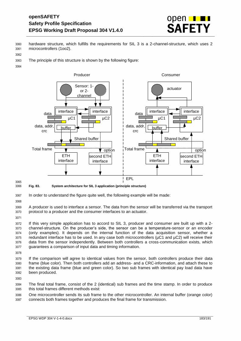
openSAFETY
Safety Profile Specification
EPSG Working Draft Proposal 304 V1.4.0
EPSG WDP 304 V-1-4-0.docx 183/191
hardware structure, which fulfills the requirements for SIL 3 is a 2-channel-structure, which uses 2 3060
microcontrollers (1oo2). 3061
3062
The principle of this structure is shown by the following figure: 3063
3064
Producer Consumer
Sensor: 1-
or 2-
channel
µC1µC2
interfacedata
data, addr,
crcbuffer
Shared buffer
ETH
interface
Total frame
second ETH
interface
µC1 µC2
interface interface interfacedata
data, addr,
crc
Shared buffer
buffer
Total frame
second ETH
interface
ETH
interface
option
actuator
option
EPL 3065
Fig. 83. System architecture for SIL 3 application (principle structure) 3066
In order to understand the figure quite well, the following example will be made: 3067
3068
A producer is used to interface a sensor. The data from the sensor will be transferred via the transport 3069
protocol to a producer and the consumer interfaces to an actuator. 3070
3071
If this very simple application has to accord to SIL 3, producer and consumer are built up with a 2-3072
channel-structure. On the producer’s side, the sensor can be a temperature-sensor or an encoder 3073
(only examples). It depends on the internal function of the data acquisition sensor, whether a 3074
redundant interface has to be used. In any case both microcontrollers (µC1 and µC2) will receive their 3075
data from the sensor independently. Between both controllers a cross-communication exists, which 3076
guarantees a comparison of input data and timing information. 3077
3078
If the comparison will agree to identical values from the sensor, both controllers produce their data 3079
frame (blue color). Then both controllers add an address- and a CRC-information, and attach these to 3080
the existing data frame (blue and green color). So two sub frames with identical pay load data have 3081
been produced. 3082
3083
The final total frame, consist of the 2 (identical) sub frames and the time stamp. In order to produce 3084
this total frames different methods exist: 3085
One microcontroller sends its sub frame to the other microcontroller. An internal buffer (orange color) 3086
connects both frames together and produces the final frame for transmission. 3087

openSAFETY
Safety Profile Specification
EPSG Working Draft Proposal 304 V1.4.0
EPSG WDP 304 V-1-4-0.docx 184/191
Both microcontrollers transfer their sub frames to a “shared buffer” which is a part of the 3088
system’s firmware (orange color, dotted line). The shared buffer connects both sub frames 3089
and produces the total frame. 3090
There are 2 independent ETH interfaces which directly transfer the sub frames to the 3091
connected network (grey color). 3092
3093
The last solution is not recommended, because Ethernet will add a lot of overhead data to each frame. 3094
So the total frame length will increase in comparison to the first and second method. In addition to the 3095
shown principles of connecting both sub frames a lot of principles will exist. All these principles have 3096
the same feature: A redundant frame will be produced, which contains a lot of principles in order to 3097
detect systematic and stochastic failures. Even if the total frame will be cut into peaces or destroyed 3098
by some unknown mechanisms, most failures, which can happen, will be detected immediately. 3099
3100
The shown structure for producing a safety related total frame only reaches the requirement for safety 3101
in accordance to SIL 3, if on the other hand the consumer will receive the frame and checks whether 3102
both sub frames contain identical information and will not be destroyed or changed. 3103
3104
The consumer also uses two microcontrollers, which are supplied by different network-interfaces, a 3105
shared buffer or a buffer, which is located in one of the two controllers. The whole frame will be cut 3106
into two peaces and both controllers will get their specific sub frame. In order to check the right 3107
contents following procedures have to be done: 3108
3109
Both controllers have to calculate the CRC and compare the residual from this calculation with 3110
the CRC of the received sub frame. 3111
Each controller has to check the address field in order to clarify whether the source address is 3112
well known and the consumer really will get this information. 3113
The internal data has to be evaluated in order to identify a valid information (e.g. integer value, 3114
exponent, pattern structure, physical dimension). 3115
Both controllers have to compare their valid information and find out the identical value. 3116
The time stamp has to be compared by the internal clock in order to agree to an actual (non 3117
delayed) information. This function has to be done by both controllers, because the time 3118
stamp only exists without a double frame pattern. 3119
3120
If all these tests will show a failure free frame structure, the output interface (red color) will control the 3121
connected actuator as the data frame brought out the according value. Very often the actuator is a 3122
device, which has only one channel for control (e.g. drive). In these cases the output interface has to 3123
provide a second channel to switch off the external actuator in order to limit a dangerous operation in 3124
case of a malfunction. 3125
3126
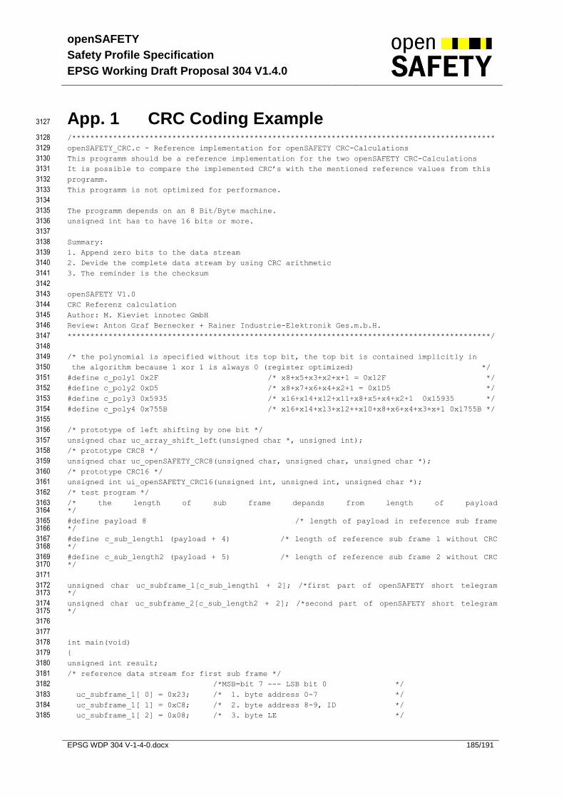
openSAFETY
Safety Profile Specification
EPSG Working Draft Proposal 304 V1.4.0
EPSG WDP 304 V-1-4-0.docx 185/191
App. 1 CRC Coding Example 3127
/********************************************************************************************* 3128
openSAFETY_CRC.c - Reference implementation for openSAFETY CRC-Calculations 3129
This programm should be a reference implementation for the two openSAFETY CRC-Calculations 3130
It is possible to compare the implemented CRC’s with the mentioned reference values from this 3131
programm. 3132
This programm is not optimized for performance. 3133
3134
The programm depends on an 8 Bit/Byte machine. 3135
unsigned int has to have 16 bits or more. 3136
3137
Summary: 3138
1. Append zero bits to the data stream 3139
2. Devide the complete data stream by using CRC arithmetic 3140
3. The reminder is the checksum 3141
3142
openSAFETY V1.0 3143
CRC Referenz calculation 3144
Author: M. Kieviet innotec GmbH 3145
Review: Anton Graf Bernecker + Rainer Industrie-Elektronik Ges.m.b.H. 3146
*********************************************************************************************/ 3147
3148
/* the polynomial is specified without its top bit, the top bit is contained implicitly in 3149
the algorithm because 1 xor 1 is always 0 (register optimized) */ 3150
#define c_poly1 0x2F /* x8+x5+x3+x2+x+1 = 0x12F */ 3151
#define c_poly2 0xD5 /* x8+x7+x6+x4+x2+1 = 0x1D5 */ 3152
#define c_poly3 0x5935 /* x16+x14+x12+x11+x8+x5+x4+x2+1 0x15935 */ 3153
#define c_poly4 0x755B /* x16+x14+x13+x12++x10+x8+x6+x4+x3+x+1 0x1755B */ 3154
3155
/* prototype of left shifting by one bit */ 3156
unsigned char uc_array_shift_left(unsigned char *, unsigned int); 3157
/* prototype CRC8 */ 3158
unsigned char uc_openSAFETY_CRC8(unsigned char, unsigned char, unsigned char *); 3159
/* prototype CRC16 */ 3160
unsigned int ui_openSAFETY_CRC16(unsigned int, unsigned int, unsigned char *); 3161
/* test program */ 3162
/* the length of sub frame depands from length of payload 3163 */ 3164
#define payload 8 /* length of payload in reference sub frame 3165 */ 3166
#define c_sub_length1 (payload + 4) /* length of reference sub frame 1 without CRC 3167 */ 3168
#define c_sub_length2 (payload + 5) /* length of reference sub frame 2 without CRC 3169 */ 3170
3171
unsigned char uc_subframe_1[c_sub_length1 + 2]; /*first part of openSAFETY short telegram 3172 */ 3173
unsigned char uc_subframe_2[c_sub_length2 + 2]; /*second part of openSAFETY short telegram 3174 */ 3175
3176
3177
int main(void) 3178
{ 3179
unsigned int result; 3180
/* reference data stream for first sub frame */ 3181
/*MSB=bit 7 --- LSB bit 0 */ 3182
uc_subframe_1[ 0] = 0x23; /* 1. byte address 0-7 */ 3183
uc_subframe_1[ 1] = 0xC8; /* 2. byte address 8-9, ID */ 3184
uc_subframe_1[ 2] = 0x08; /* 3. byte LE */ 3185

openSAFETY
Safety Profile Specification
EPSG Working Draft Proposal 304 V1.4.0
EPSG WDP 304 V-1-4-0.docx 186/191
uc_subframe_1[ 3] = 0x34; /* 4. byte CT 0-7 */ 3186
uc_subframe_1[ 4] = 0x11; /* 5. byte DB 1 */ 3187
uc_subframe_1[ 5] = 0x22; /* 6. byte DB 2 */ 3188
uc_subframe_1[ 6] = 0x33; /* 7. byte DB 3 */ 3189
uc_subframe_1[ 7] = 0x44; /* 8. byte DB 4 */ 3190
uc_subframe_1[ 8] = 0x55; /* 9. byte DB 5 */ 3191
uc_subframe_1[ 9] = 0x66; /* 10. byte DB 6 */ 3192
uc_subframe_1[10] = 0x77; /* 11. byte DB 7 */ 3193
uc_subframe_1[11] = 0x88; /* 12. byte DB 8 */ 3194
3195
/* reference data stream for second sub frame */ 3196
/*MSB=Bit 7 --- LSB BIT 0 */ 3197
uc_subframe_2[ 0] = 0x22; /* 1. byte address xor domain 0-7 */ 3198
uc_subframe_2[ 1] = 0xC8; /* 2. byte address xor domain 8-9, ID */ 3199
uc_subframe_2[ 2] = 0x12; /* 3. byte CT 8-15 */ 3200
uc_subframe_2[ 3] = 0x56; /* 4. byte TADR 0-7 */ 3201
uc_subframe_2[ 4] = 0x30; /* 5. byte TADR 8-9, TR */ 3202
uc_subframe_2[ 5] = 0x11; /* 6. byte DB 1 */ 3203
uc_subframe_2[ 6] = 0x22; /* 7. byte DB 2 */ 3204
uc_subframe_2[ 7] = 0x33; /* 8. byte DB 3 */ 3205
uc_subframe_2[ 8] = 0x44; /* 9. byte DB 4 */ 3206
uc_subframe_2[ 9] = 0x55; /* 10. byte DB 5 */ 3207
uc_subframe_2[10] = 0x66; /* 11. byte DB 6 */ 3208
uc_subframe_2[11] = 0x77; /* 12. byte DB 7 */ 3209
uc_subframe_2[12] = 0x88; /* 13. byte DB 8 */ 3210
3211
/* calculation of CRCs with reference data stream */ 3212
result = uc_openSAFETY_CRC8(c_sub_length1, c_poly1, &uc_subframe_1[0]); 3213
/* result = 0x3c */ 3214
uc_subframe_1[c_sub_length1] = result; /* 13. byte CRC-8 bit 0-7 */ 3215
result = uc_openSAFETY_CRC8(c_sub_length2, c_poly2, &uc_subframe_2[0]); 3216
/* result = 0x4f */ 3217
uc_subframe_2[c_sub_length2] = result; /* 14. byte CRC-8 bit 0-7 */ 3218
result = ui_openSAFETY_CRC16(c_sub_length1, c_poly3, &uc_subframe_1[0]); 3219
/* result = 0x0374 */ 3220
uc_subframe_1[c_sub_length1] = result >> 8; /* 13. byte CRC-16 bit 15-8 */ 3221
uc_subframe_1[c_sub_length1+1] = result; /* 14. byte CRC-16 bit 0-7 */ 3222
3223
result = ui_openSAFETY_CRC16(c_sub_length2, c_poly4, &uc_subframe_2[0]); 3224
/* result = 07031 */ 3225
uc_subframe_2[c_sub_length2] = result >> 8; /* 14. byte CRC-16 bit 15-8 */ 3226
uc_subframe_2[c_sub_length2+1] = result; /* 15. byte CRC-16 bit 0-7 */ 3227
3228
return 0; 3229
} 3230
3231
3232
/********************************************************************************************* 3233
function uc_openSAFETY_CRC8() version 1.0 3234
date 2005-04-22 3235
author: m.kieviet 3236
maxmuim datalength of 14 byte 3237
return: unsinged char checksum 3238
parameter: 1 byte frame length 3239
1 byte polynominal 3240
1 pointer start adress of frame array 3241
*********************************************************************************************/ 3242
unsigned char uc_openSAFETY_CRC8(unsigned char uc_sub_length, 3243
unsigned char uc_poly, 3244
unsigned char *uc_subframe) 3245
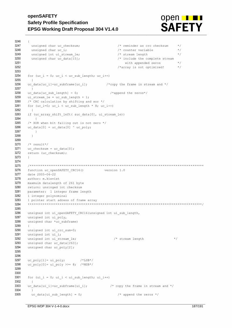
openSAFETY
Safety Profile Specification
EPSG Working Draft Proposal 304 V1.4.0
EPSG WDP 304 V-1-4-0.docx 187/191
{ 3246
unsigned char uc_checksum; /* reminder as crc checksum */ 3247
unsigned char uc_i; /* counter variable */ 3248
unsigned int ui_stream_le; /* stream length */ 3249
unsigned char uc_data[15]; /* include the complete stream 3250
with appended zeros */ 3251
/*array is not optimized! */ 3252
3253
for (uc_i = 0; uc_i < uc_sub_length; uc_i++) 3254
{ 3255
uc_data[uc_i]=uc_subframe[uc_i]; /*copy the frame in stream and */ 3256
} 3257
uc_data[uc_sub_length] = 0; /*append the zeros*/ 3258
ui_stream_le = uc_sub_length + 1; 3259
/* CRC calculation by shifting and xor */ 3260
for (uc_i=0; uc_i < uc_sub_length * 8; uc_i++) 3261
{ 3262
if (uc_array_shift_left( &uc_data[0], ui_stream_le)) 3263
{ 3264
/* XOR when bit falling out is not zero */ 3265
uc_data[0] = uc_data[0] ^ uc_poly; 3266
} 3267
} 3268
3269
/* result*/ 3270
uc_checksum = uc_data[0]; 3271
return (uc_checksum); 3272
} 3273
3274
/********************************************************************************************* 3275
function uc_openSAFETY_CRC16() version 1.0 3276
date 2005-04-22 3277
author: m.kieviet 3278
maxmuim datalength of 261 byte 3279
return: unsinged int checksum 3280
parameter: 1 integer frame length 3281
1 integer polynominal 3282
1 pointer start adress of frame array 3283
*********************************************************************************************/ 3284
3285
unsigned int ui_openSAFETY_CRC16(unsigned int ui_sub_length, 3286
unsigned int ui_poly, 3287
unsigned char *uc_subframe) 3288
{ 3289
unsigned int ui_crc_sum=0; 3290
unsigned int ui_i; 3291
unsigned int ui_stream_le; /* stream length */ 3292
unsigned char uc_data[263]; 3293
unsigned char uc_poly[2]; 3294
3295
3296
uc_poly[1]= ui_poly; /*LSB*/ 3297
uc_poly[0]= ui_poly >>= 8; /*MSB*/ 3298
3299
3300
for (ui_i = 0; ui_i < ui_sub_length; ui_i++) 3301
{ 3302
uc_data[ui_i]=uc_subframe[ui_i]; /* copy the frame in stream and */ 3303
} 3304
uc_data[ui_sub_length] = 0; /* append the zeros */ 3305
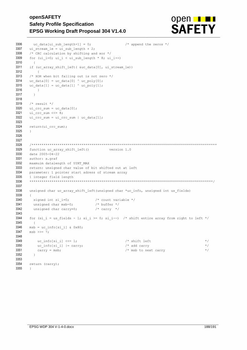
openSAFETY
Safety Profile Specification
EPSG Working Draft Proposal 304 V1.4.0
EPSG WDP 304 V-1-4-0.docx 188/191
uc_data[ui_sub_length+1] = 0; /* append the zeros */ 3306
ui_stream_le = ui_sub_length + 2; 3307
/* CRC calculation by shifting and xor */ 3308
for (ui_i=0; ui_i < ui_sub_length * 8; ui_i++) 3309
{ 3310
if (uc_array_shift_left( &uc_data[0], ui_stream_le)) 3311
{ 3312
/* XOR when bit falling out is not zero */ 3313
uc_data[0] = uc_data[0] ^ uc_poly[0]; 3314
uc_data[1] = uc_data[1] ^ uc_poly[1]; 3315
} 3316
} 3317
3318
/* result */ 3319
ui_crc_sum = uc_data[0]; 3320
ui_crc_sum <<= 8; 3321
ui_crc_sum = ui_crc_sum | uc_data[1]; 3322
3323
return(ui_crc_sum); 3324
} 3325
3326
3327
/********************************************************************************************* 3328
function uc_array_shift_left() version 1.0 3329
date 2005-04-22 3330
author: a.graf 3331
maxmuim datalength of UINT_MAX 3332
return: unsigned char value of bit shifted out at left 3333
parameter: 1 pointer start adress of stream array 3334
1 integer field length 3335
********************************************************************************************/ 3336
3337
unsigned char uc_array_shift_left(unsigned char *uc_info, unsigned int us_fields) 3338
{ 3339
signed int si_i=0; /* count variable */ 3340
unsigned char msb=0; /* buffer */ 3341
unsigned char carry=0; /* carry */ 3342
3343
for (si_i = us_fields - 1; si_i >= 0; si_i--) /* shift entire array from right to left */ 3344
{ 3345
msb = uc_info[si_i] & 0x80; 3346
msb >>= 7; 3347
3348
uc_info[si_i] <<= 1; /* shift left */ 3349
uc_info[si_i] |= carry; /* add carry */ 3350
carry = msb; /* msb to next carry */ 3351
} 3352
3353
return (carry); 3354
} 3355
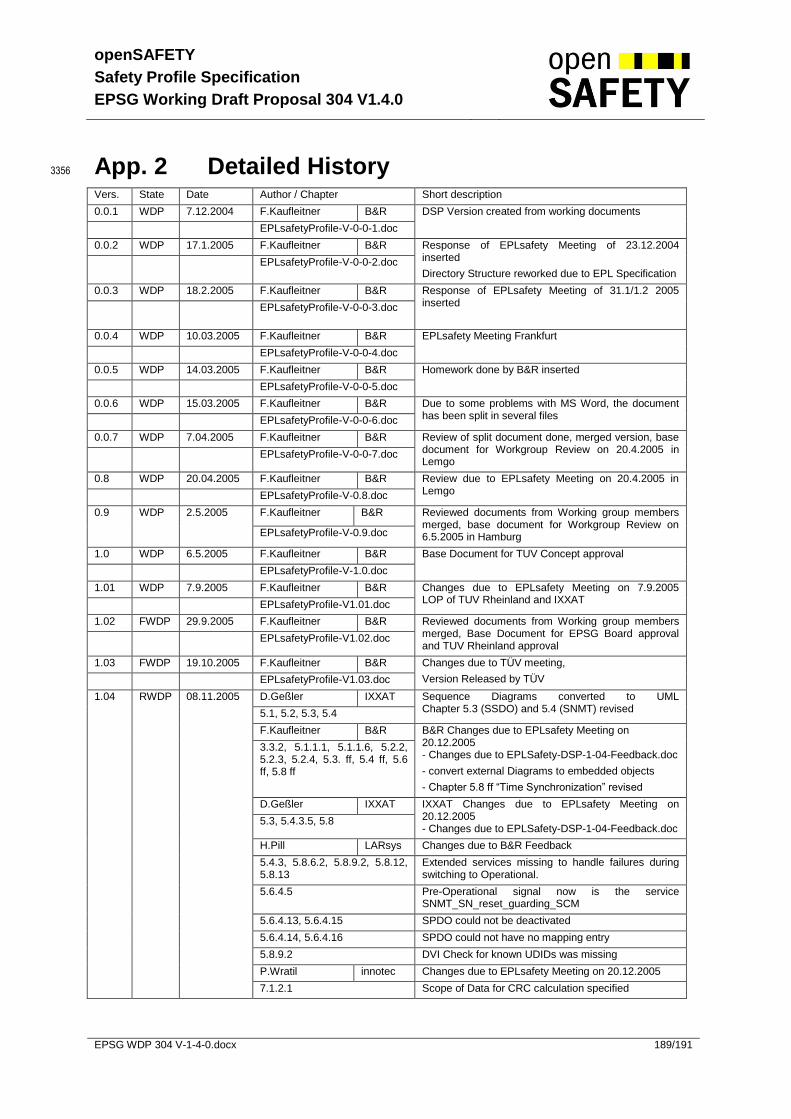
openSAFETY
Safety Profile Specification
EPSG Working Draft Proposal 304 V1.4.0
EPSG WDP 304 V-1-4-0.docx 189/191
App. 2 Detailed History 3356
Vers. State Date Author / Chapter Short description
0.0.1 WDP 7.12.2004 F.Kaufleitner B&R DSP Version created from working documents
EPLsafetyProfile-V-0-0-1.doc
0.0.2 WDP 17.1.2005 F.Kaufleitner B&R Response of EPLsafety Meeting of 23.12.2004 inserted
Directory Structure reworked due to EPL Specification EPLsafetyProfile-V-0-0-2.doc
0.0.3 WDP 18.2.2005 F.Kaufleitner B&R Response of EPLsafety Meeting of 31.1/1.2 2005 inserted
EPLsafetyProfile-V-0-0-3.doc
0.0.4 WDP 10.03.2005 F.Kaufleitner B&R EPLsafety Meeting Frankfurt
EPLsafetyProfile-V-0-0-4.doc
0.0.5 WDP 14.03.2005 F.Kaufleitner B&R Homework done by B&R inserted
EPLsafetyProfile-V-0-0-5.doc
0.0.6 WDP 15.03.2005 F.Kaufleitner B&R Due to some problems with MS Word, the document has been split in several files EPLsafetyProfile-V-0-0-6.doc
0.0.7 WDP 7.04.2005 F.Kaufleitner B&R Review of split document done, merged version, base document for Workgroup Review on 20.4.2005 in Lemgo
EPLsafetyProfile-V-0-0-7.doc
0.8 WDP 20.04.2005 F.Kaufleitner B&R Review due to EPLsafety Meeting on 20.4.2005 in Lemgo EPLsafetyProfile-V-0.8.doc
0.9 WDP 2.5.2005 F.Kaufleitner B&R Reviewed documents from Working group members merged, base document for Workgroup Review on 6.5.2005 in Hamburg EPLsafetyProfile-V-0.9.doc
1.0 WDP 6.5.2005 F.Kaufleitner B&R Base Document for TUV Concept approval
EPLsafetyProfile-V-1.0.doc
1.01 WDP 7.9.2005 F.Kaufleitner B&R Changes due to EPLsafety Meeting on 7.9.2005 LOP of TUV Rheinland and IXXAT EPLsafetyProfile-V1.01.doc
1.02 FWDP 29.9.2005 F.Kaufleitner B&R Reviewed documents from Working group members merged, Base Document for EPSG Board approval and TUV Rheinland approval
EPLsafetyProfile-V1.02.doc
1.03 FWDP 19.10.2005 F.Kaufleitner B&R Changes due to TÜV meeting,
Version Released by TÜV EPLsafetyProfile-V1.03.doc
1.04 RWDP 08.11.2005 D.Geßler IXXAT Sequence Diagrams converted to UML Chapter 5.3 (SSDO) and 5.4 (SNMT) revised 5.1, 5.2, 5.3, 5.4
F.Kaufleitner B&R B&R Changes due to EPLsafety Meeting on 20.12.2005 - Changes due to EPLSafety-DSP-1-04-Feedback.doc
- convert external Diagrams to embedded objects
- Chapter 5.8 ff “Time Synchronization” revised
3.3.2, 5.1.1.1, 5.1.1.6, 5.2.2, 5.2.3, 5.2.4, 5.3. ff, 5.4 ff, 5.6 ff, 5.8 ff
D.Geßler IXXAT IXXAT Changes due to EPLsafety Meeting on 20.12.2005 - Changes due to EPLSafety-DSP-1-04-Feedback.doc
5.3, 5.4.3.5, 5.8
H.Pill LARsys Changes due to B&R Feedback
5.4.3, 5.8.6.2, 5.8.9.2, 5.8.12, 5.8.13
Extended services missing to handle failures during switching to Operational.
5.6.4.5 Pre-Operational signal now is the service SNMT_SN_reset_guarding_SCM
5.6.4.13, 5.6.4.15 SPDO could not be deactivated
5.6.4.14, 5.6.4.16 SPDO could not have no mapping entry
5.8.9.2 DVI Check for known UDIDs was missing
P.Wratil innotec Changes due to EPLsafety Meeting on 20.12.2005
7.1.2.1 Scope of Data for CRC calculation specified

openSAFETY
Safety Profile Specification
EPSG Working Draft Proposal 304 V1.4.0
EPSG WDP 304 V-1-4-0.docx 190/191
DSP 16.12.2005 V.Sasse KW-Software
Technical Working Group released EPLsafety as a Draft Standard Proposal (DSP). The EPLsafety specification will be proofed fort two month by the EPSG members
EPLsafetyProfile-V1.04.doc
1.05 DSP 24.4.2006 F.Kaufleitner B&R Changes due to EPLsafety Meeting on 24.4.2006 according the Feedback List of the Review Phase. EPLsafetyProfile-V1.05a.doc
5.3.2.3, 5.3.2.4, 5.4.2.1, 5.4.2.2, 5.4.3.2, 5.4.3.7, 5.6.4.4,. 5.6.4.11, 5.6.4.12, 5.6.4.17, 5.8.2.3, 5.8.9.2, 5.8.12,
25.4.2006 F.Kaufleitner B&R B&R Changes due to EPLsafety Meeting on 24.4.2006 EPLsafetyProfile-V1.05b.doc
2.1
13.07.2006 P.Wratil innotec Innotec Changes due to EPLsafety Meeting on 24.4.2006 resulting in using the same CRC polynomial for subframe one and subframe two.
EPLsafetyProfile-V1.05c.doc
7.1.2.1
23.10.2006 H.Pill LARsys Several changes due to EPLsafety Stack Implementation EPLsafetyProfile-V1.05d.doc
5.3.2.3, 5.3.2.4, 5.3.2.5, 5.4.2.3, 5.4.3.2, 5.6.4, 5.6.4.3, 5.6.4.4, 5.6.4.5, 5.6.4.10, 5.6.4.12, 5.6.4.17, 5.8.6.1, 5.8.6.2, 5.8.9, 5.8.10, 5.8.12.1, 5.8.13,
24.10.2006 F.Kaufleitner B&R Using the same CRC polynomial for subframe one and subframe two. EPLsafetyProfile-V1.05e.doc
5.1.1.8
3.11.2006 F.Kaufleitner B&R Changes due to EPLsafety Meeting on 03.11.2006 at IXXAT / Weingarten Object 1200h, Subindex 3, datatype changed from INTEGER8 to UNSIGNED8
Object 100Dh renamed to SNMT_ResetGuarding_U32
Service SMNT_SN_calc_CRC renamed to SNMT_SN_busy
Technical Working Group released EPLsafety as a new Draft Standard Proposal (DSP
5.6.4.6
5.4.3.2
EPLsafetyProfile-V1.05.doc
1.06 DSP 21.05.2007 F.Kaufleitner B&R Coding the UDID of the SCM to sub frame one
PowerlinkSafetyProfile-V1.06a.doc
2.3.2.2 openSAFETY Domain Separation - No mandatory firewalls
5.1.1 Structure of openSAFETY Frame - xor of UDID of SCM on sub frame two of SPDO / SSDO
5.1.1.11 UDID of SCM coding (UDID of SCM) - new chapter
5.4.3 SNMT Extended Services - Additional SNMT service
5.4.3.8 UDID of SCM assignment – new chapter
5.6.4.9 Object 1019h: Unique Device ID - UDID changed to 6 Bytes
5.6.4.12 Object 1200h: Common Communication Parameter - New Object for UDIDofSCM
5.6.4.22 Object CC01h – CFFFh: SADR-UDID List - UDID changed to 6 Bytes
5.7.6.2 Pre-Operational - Receiving new SNMT
5.7.10 Safety Address Verification - Sending new SNMT
25.05.2007 F.Kaufleitner B&R UDID “00-00-00-00-00-00” for error indication
PowerlinkSafetyProfile-V1.06b.doc

openSAFETY
Safety Profile Specification
EPSG Working Draft Proposal 304 V1.4.0
EPSG WDP 304 V-1-4-0.docx 191/191
5.4.2.1 UDID Request5.4.2.2SADR assignment
5.4.2.2 SADR assignment
5.4.3.8 UDID of SCM assignment
5.6.4.9 Object 1019h: Unique Device ID - UDID changed to 6 Bytes
Major changes within version 1.06 against version 1.03 (last version released by TÜV Rheinland)
Using the same CRC polynomial for subframe one and subframe two
XOR of UDID of SCM on sub frame two of SPDO / SSDO, as a result of this measure, the openSAFETY Domain Separation isn’t safety critical anymore
1.07 DSP 08.08.2007 F.Kaufleitner B&R Feedback of Working Group implemented
PowerlinkSafetyProfile-V1.07.doc
B&R:
0 History spitted in Major Changes in III and detailed Information in App.2
1.07a DSP 08.08.2007 F.Kaufleitner B&R Feedback of Working Group implemented
PowerlinkSafetyProfile-V1.07a.doc
IXXAT – correction due to fina Review:
5.4.2.1 LE in response changed to 6
5.4.2.2 LE changed to 6
5.4.3.8 LE changed to 7
5.6.4.12 Data type changed form USINT8 to INTEGER8
1.08 WDP 30.6.2009 F.Kaufleitner B&R Working Draft Proposal
EPSG WDP 304 V-1-0-8.doc
Formal Changes Corrections according saving parametes on SN
document converted due to new template filename adapted to new naming convetion errors in Fig 76 (State diagram “Activate SN”) and Fig 72 (State diagram “SCM Operational”) corrected
3357