safety notice
TRANSCRIPT
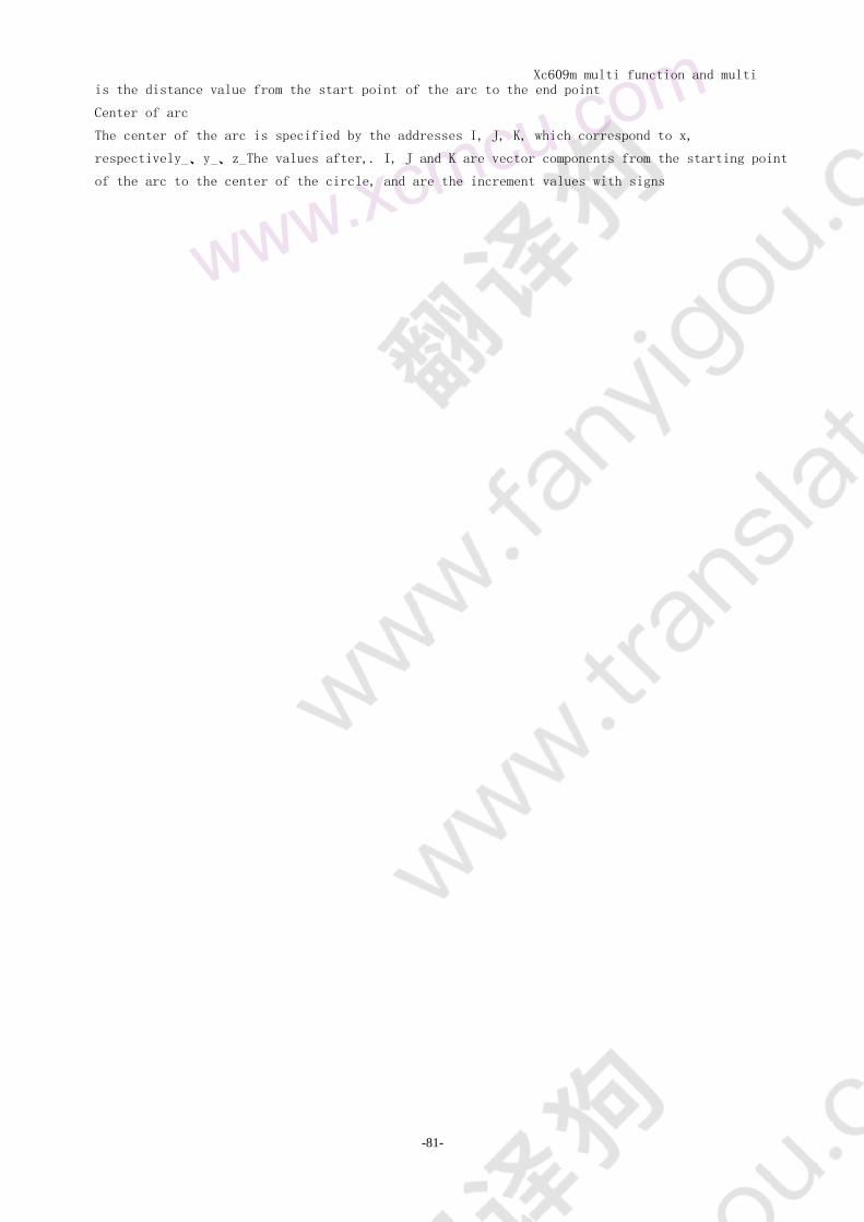
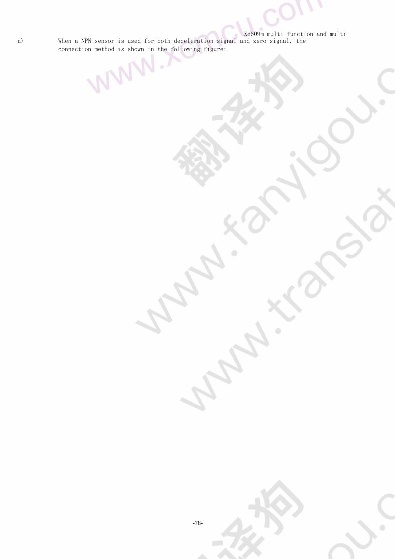
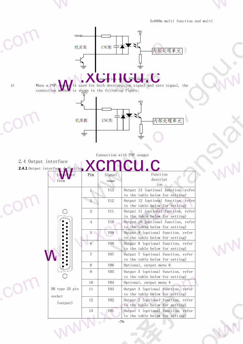
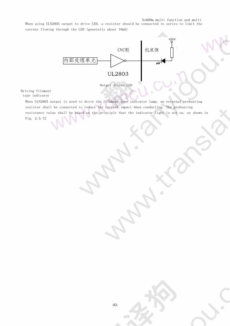
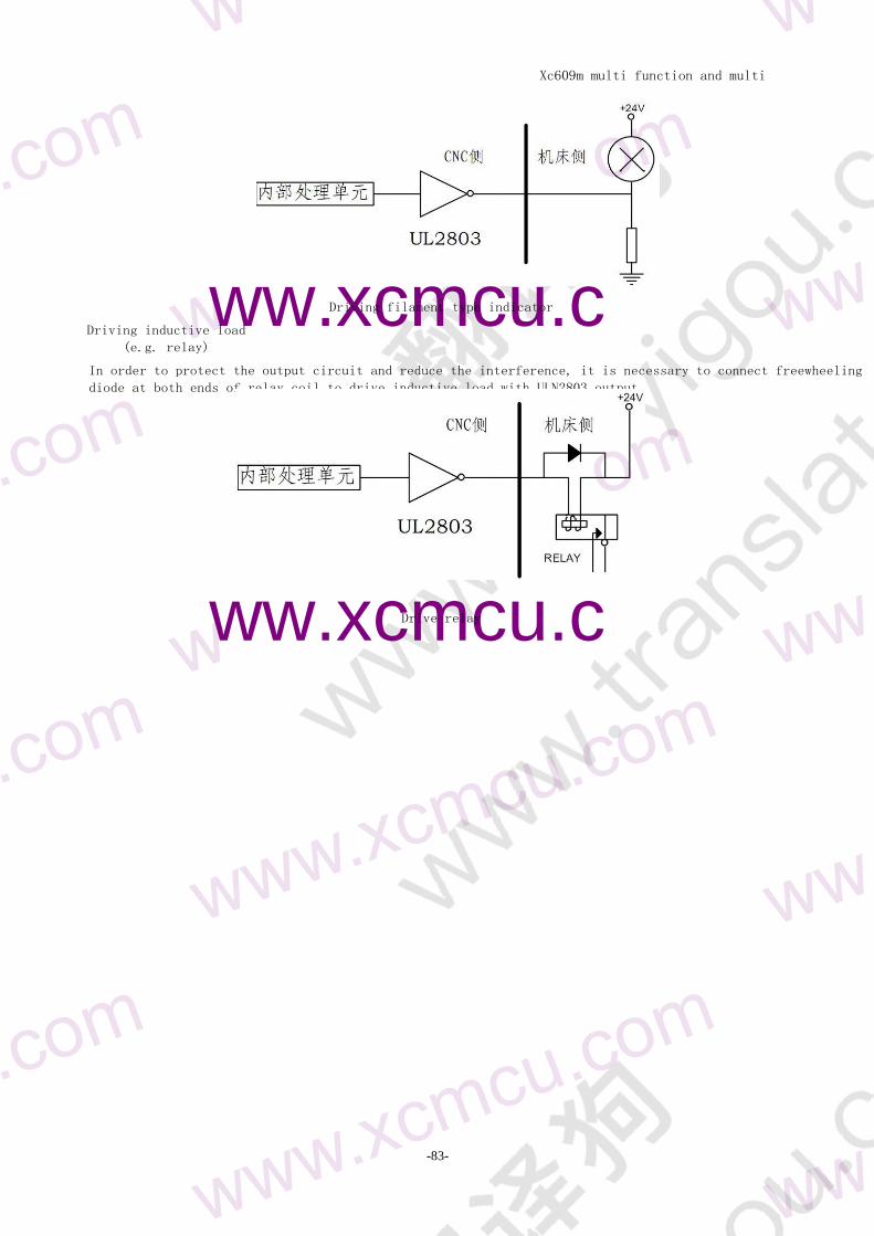
Xc609m multi function and multi
purpose CNC System Manual
-1-
Safety notice Before using the control system please read this manual carefully before operating Please
check whether the wiring is correct before power on
The operation and use of the product are described in this manual as much as possible However
due to too many possibilities involved it is impossible to explain all the allowed and
disallowed operations Therefore in order to ensure the normal use of the product and the
safety of personnel and equipment the operation not stated in the instruction manual shall be
deemed as not allowed
bull Working environment and protection
1 The working environment temperature of the control system is - 10 ~ 50 When the
temperature exceeds the ambient temperature the system may work abnormally or even crash
When the temperature is too low the LCD will display abnormally
2 The relative humidity should be controlled at 0-85
3 When working in the environment of high temperature high humidity and corrosive gas special
protective measures must be taken
4 Prevent dust dust metal dust and other debris into the control system
5 The LCD screen of the control system should be well protected keep it away from sharp
objects prevent objects in the air from hitting the screen when there is dust on the
screen wipe it gently with soft paper towel or cotton cloth
bull System operation
When the system is operating it is necessary to press the corresponding operation button When
pressing the key press it with the belly of the index finger or the middle finger Do not press
the button with the fingernail otherwise the mask of the key will be damaged and your use will
be affected
The operator for the first time should understand the correct use method of the corresponding
function before carrying out the corresponding operation For unfamiliar functions or parameters
it is strictly forbidden to operate or change the system parameters at will
For problems in operation we provide telephone consultation service
bull System maintenance
Operators without strict training or units or individuals not authorized by the company shall
not open the control system for maintenance operation otherwise the consequences shall be borne
by themselves
bull System warranty Description
Warranty period within 24 months from the date of delivery
Warranty scope during the warranty period any failure
occurred under the condition of operation according to the use
requirements During the warranty period the fault beyond the
warranty scope is charged service
Out of the warranty period all troubleshooting services are charged
The following conditions are not covered by the warranty
1 Any man-made failure or accidental failure in violation of the use requirements any human failure
or accidental failure in violation of the use requirements
Xc609m multi function and multi
purpose CNC System Manual
-2-
2 Refer to the manual of plug in and out of the system and the wiring is not damaged due to wrong
connection
3 Refer to the manual of plug in and out of the system and the wiring is not damaged due to wrong
connection
4 Damage caused by natural disasters etc
5 Damage caused by unauthorized disassembly modification repair etc
bull Other matters
If there is any discrepancy or incompleteness between the
manual and the system function the system software
function shall prevail The control system function is
subject to change or improvement (upgrade) without prior
notice
Only one copy of operation manual is provided free of charge If you need the latest
operation manual you can get the electronic version (PDF format) for free and inform your e-
mail mailbox to send it in the form of e-mail
The product functions described in this manual are only for this product The actual function
configuration and technical performance of the CNC machine tool installed with this product are
provided by the machine tool manufacturer
Design decision CNC machine tool function configuration and technical indicators to the machine
manufacturers instructions
Xc609m multi function and multi
purpose CNC System Manual
-3-
order record Safety notice 1
Part 1 System Overview 7
11 System introduction 7
12 technical specifications 7
Part II operation instructions 9
Chapter I description of operation authority 9
11 permission level 9
12 Operation authority 9
Chapter 2 interface setting 10
21 panel 10
211 description 11
212 Character number edit key 11
213 Function operation key of machine tool 12
22 page display 14
221 Page layout 14
222 Page display content 14
223 Soft function key menu 15
23 position screen 16
231 Picture composition 16
232 Drilling function setting screen 16
233 G88 editing 17
234 Multi hole editing 17
235 Coordinate setting 18
236 Set coordinates 18
237 Line segmentation 18
238 Center coordinates 19
239 Brief display 19
2310 user interface 20
2311 User interface management 20
24 program screen 21
241 Program content screen 21
242 Local directory screen 22
243 U disk directory screen 22
25 offset screen 22
251 tool compensation screen 22
26 parameter screen 23
261 Parameter synthesis screen 23
262 Input port parameter screen 23
263 Output parameter screen 23
263 Direct control parameter screen 24
264 Axis parameter screen 24
Screen information 25
271 Alarm information screen 25
Xc609m multi function and multi
purpose CNC System Manual
-4-
272 System information screen 25
273 Password and change time screen 26
28 diagnosis screen 26
281 Input diagnosis screen 26
282 Output diagnosis screen 26
283 Auxiliary relay diagnosis screen 27
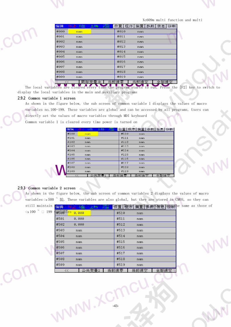
29 Macro variable screen 27
291 Local variable screen 27
292 Common variable 1 screen 28
293 Common variable 2 screen 28
Chapter 3 manual operation 29
31 return to mechanical zero operation 29
32 manual feed 29
33 single step feed 29
34 hand wheel feed 30
35 Manual auxiliary operation 30
351 Manual coolant switch 30
352 Manual clamping switch 30
353 Manual spindle control 30
Chapter 4 automatic operation 31
41 program operation 31
42 multi segment operation of MDI 32
Chapter V trial operation 34
51 Feed rate multiplier 34
52 Rate rapid feed 34
53 one way sequence section 34
54 skip optional segments 35
Chapter 6 safe operation 36
61 power on 36
62 shutdown 36
63 Super program protection 36
631 Hardware over range protection 36
632 Over range protection software 36
64 emergency operation 36
641 reset 36
642 emergency stop 36
643 cut off the power supply 36
Chapter 7 program editing 37
71 general 37
72 teaching procedure 37
73 new program 38
74 insert one line program segment 38
Chapter 3 programming instructions 39
Chapter 1 Introduction to programming 39
11 absolute value instruction 39
12 increment value instruction 39
Xc609m multi function and multi
purpose CNC System Manual
-5-
13 control shaft 39
131 number of control axles 39
132 units 39
14 decimal point programming 40
Chapter II composition of procedure 41
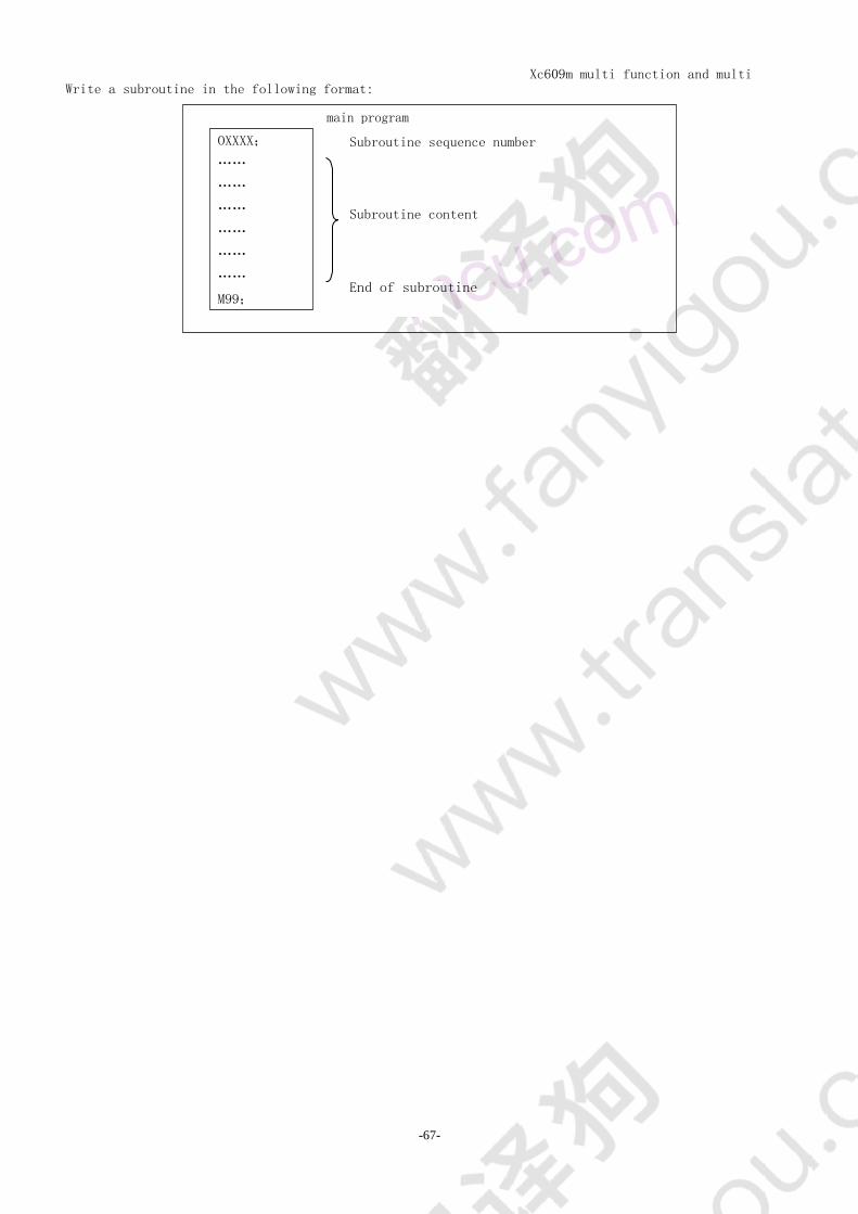
21 procedure 41
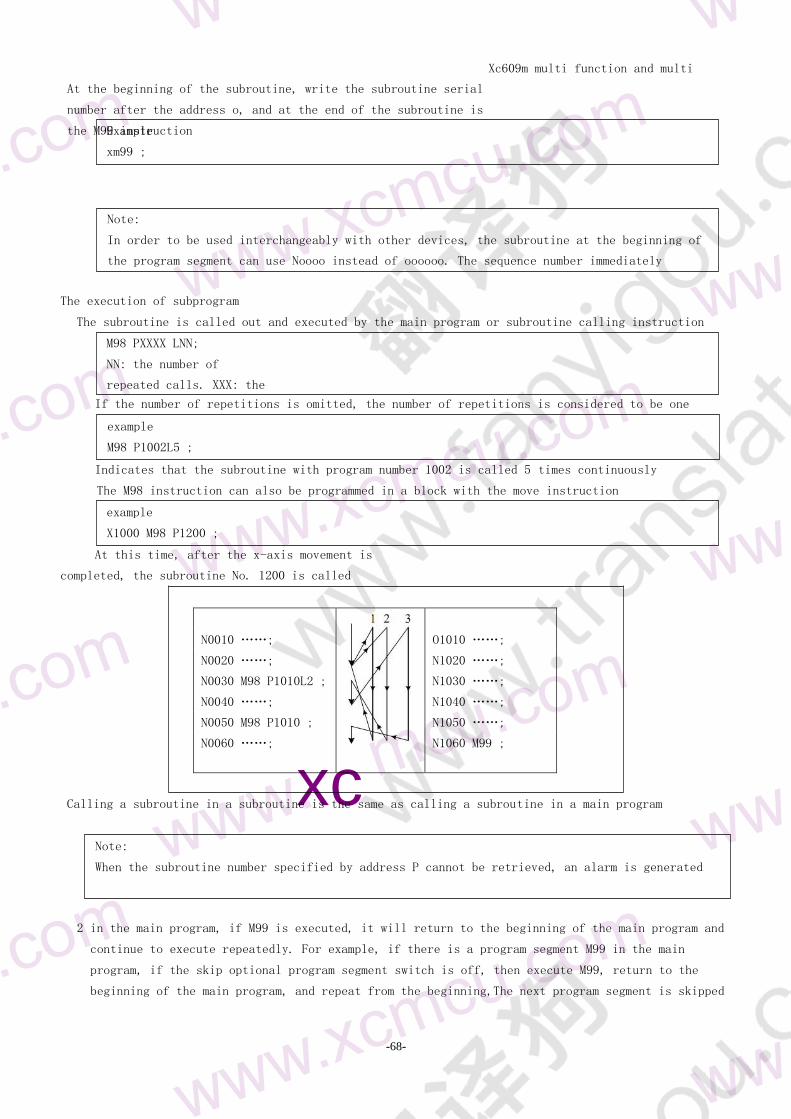
211 main program and subprogram 41
212 program number 43
213 Program number and program segment 43
214 Skip optional segments 43
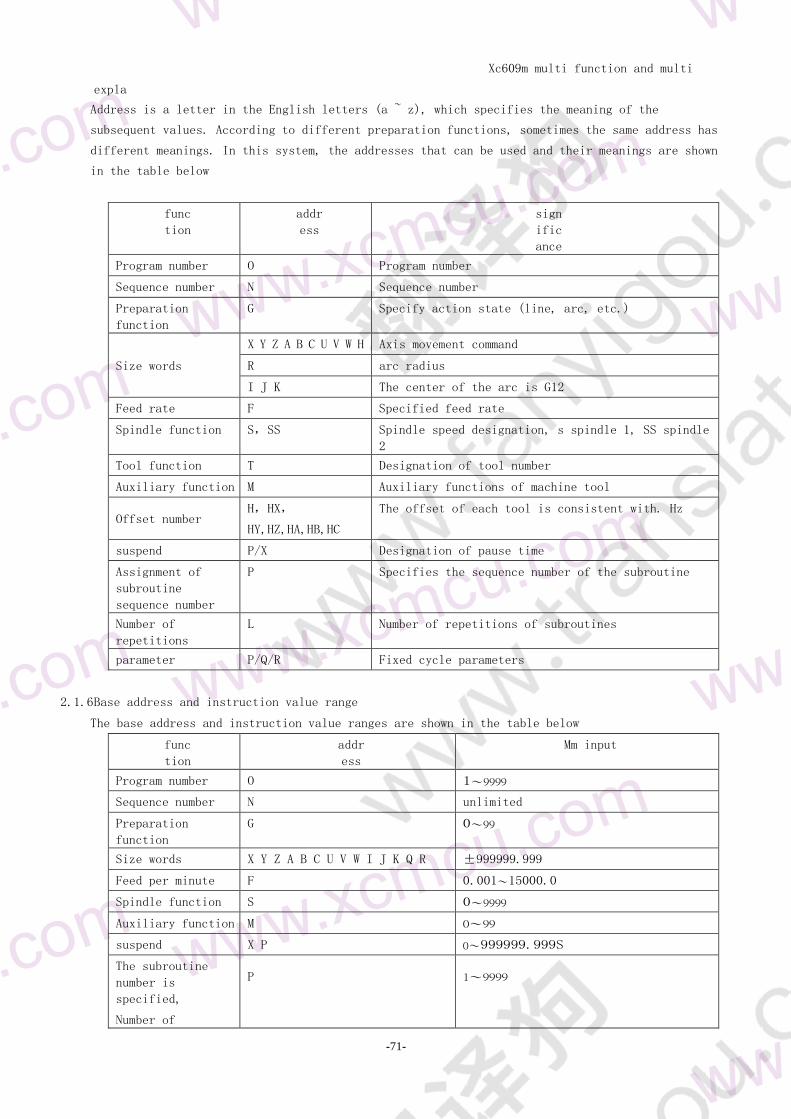
215 Word and address 43
216 Base address and instruction value range 44
22 end of procedure 44
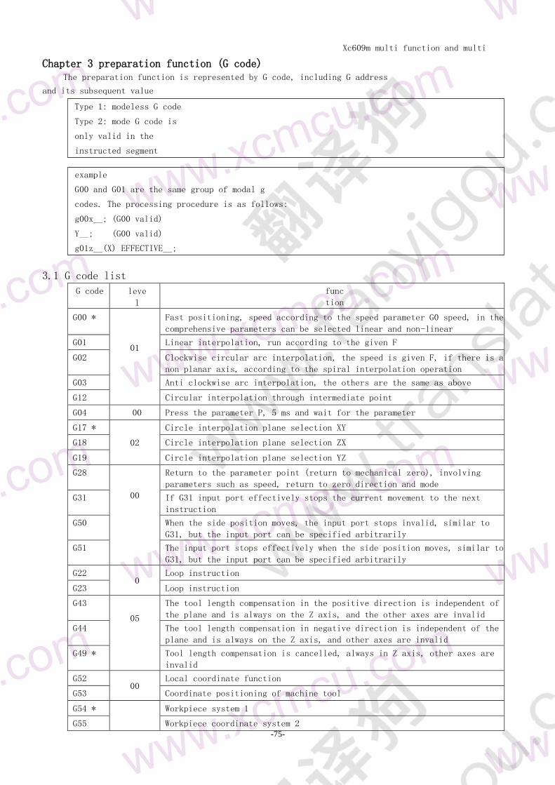
Chapter 3 preparation function (G code) 46
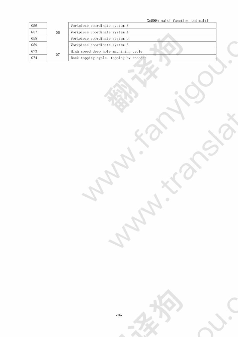
31 G code list 46
32 G00 - fast positioning 47
33 G01 linear interpolation 48
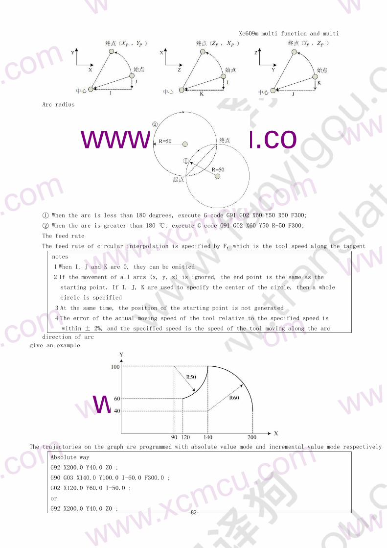
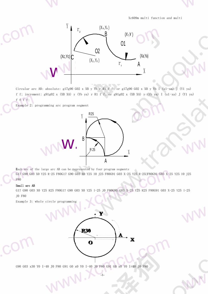
34 G022G03 - CIRCULAR INTERPOLATION 48
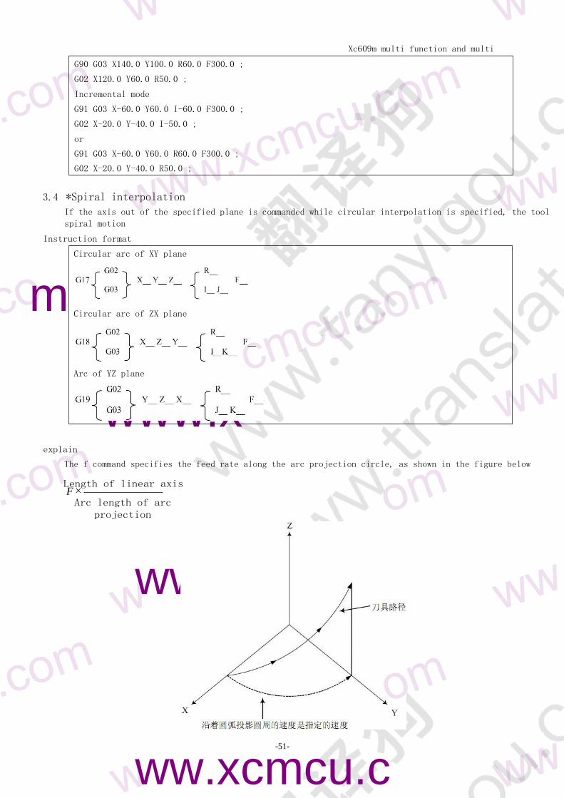
34 spiral interpolation 51
35 G12-3 POINT CIRCULAR INTERPOLATION 52
36 G04 delay wait 52
37 reference point function 52
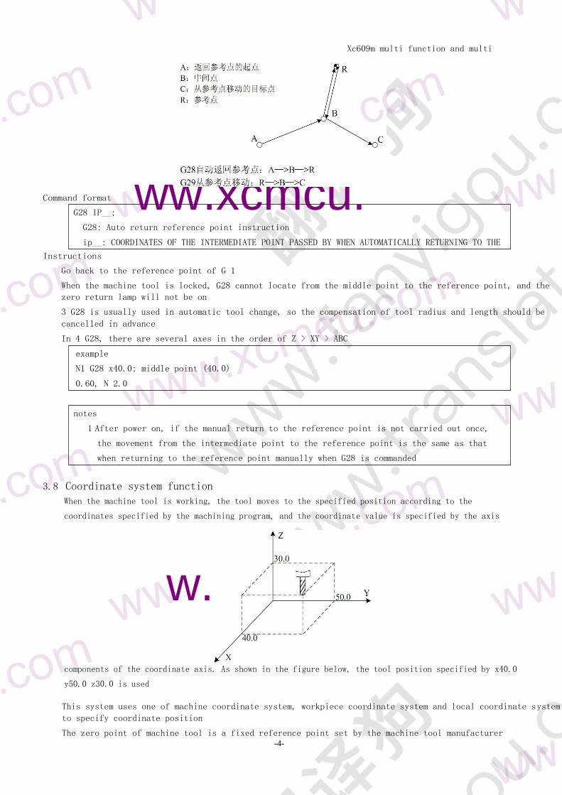
371 G28 - automatic return to reference point 52
38 coordinate system function 53
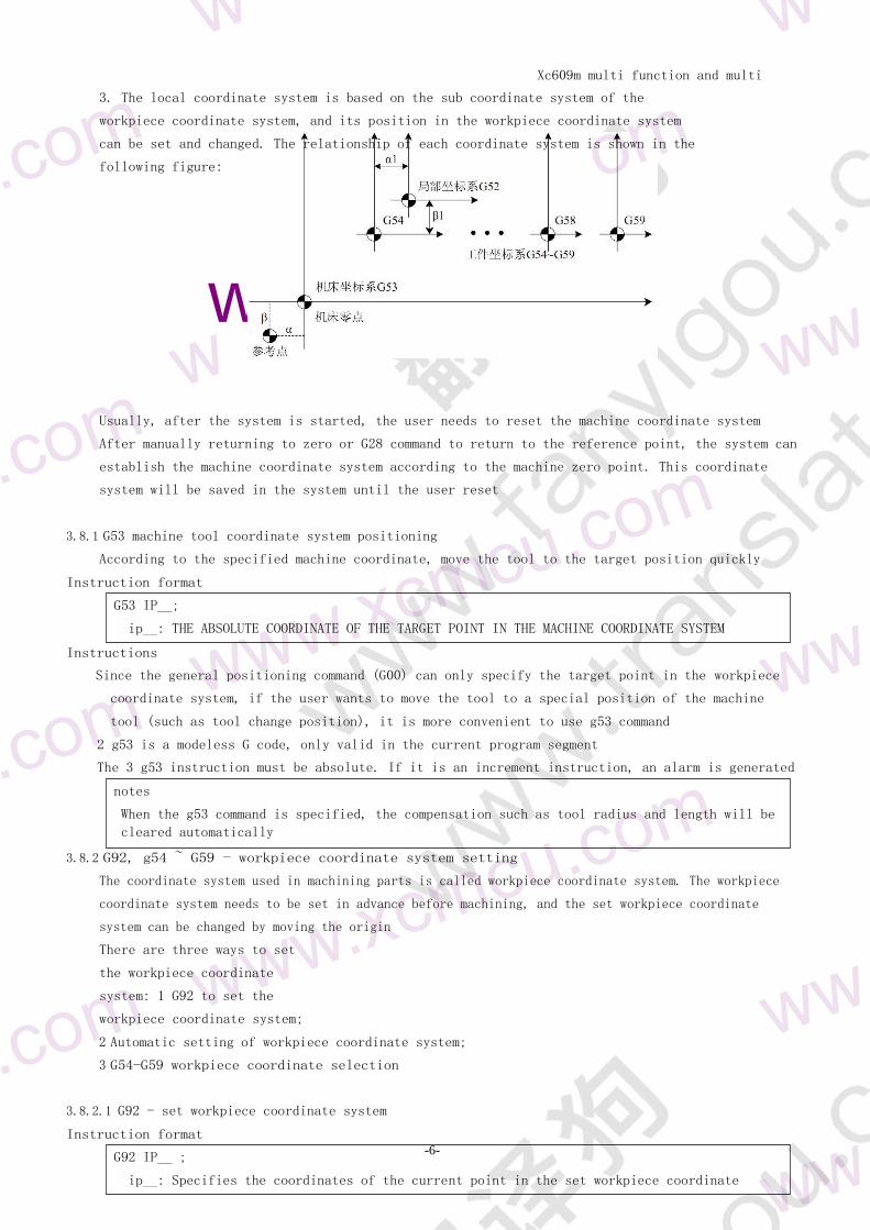
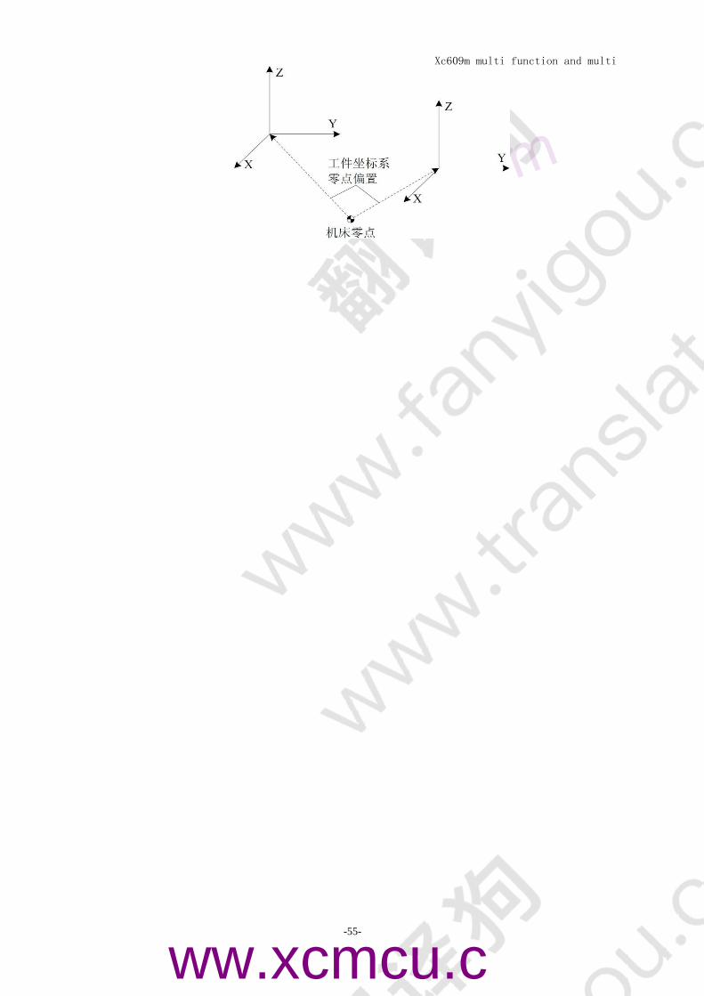
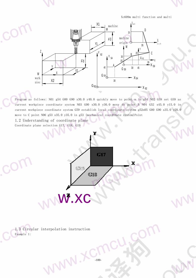
381 G53 - MACHINE TOOL COORDINATE SYSTEM POSITIONING 54
382 G92 G54-G59 - workpiece coordinate system setting 54
383 moving the workpiece coordinate system with G92 56
384 setting machine coordinates (G93) 56
385 G52 local coordinate system 56
386 G177G188G19 - PLANE SELECTION 57
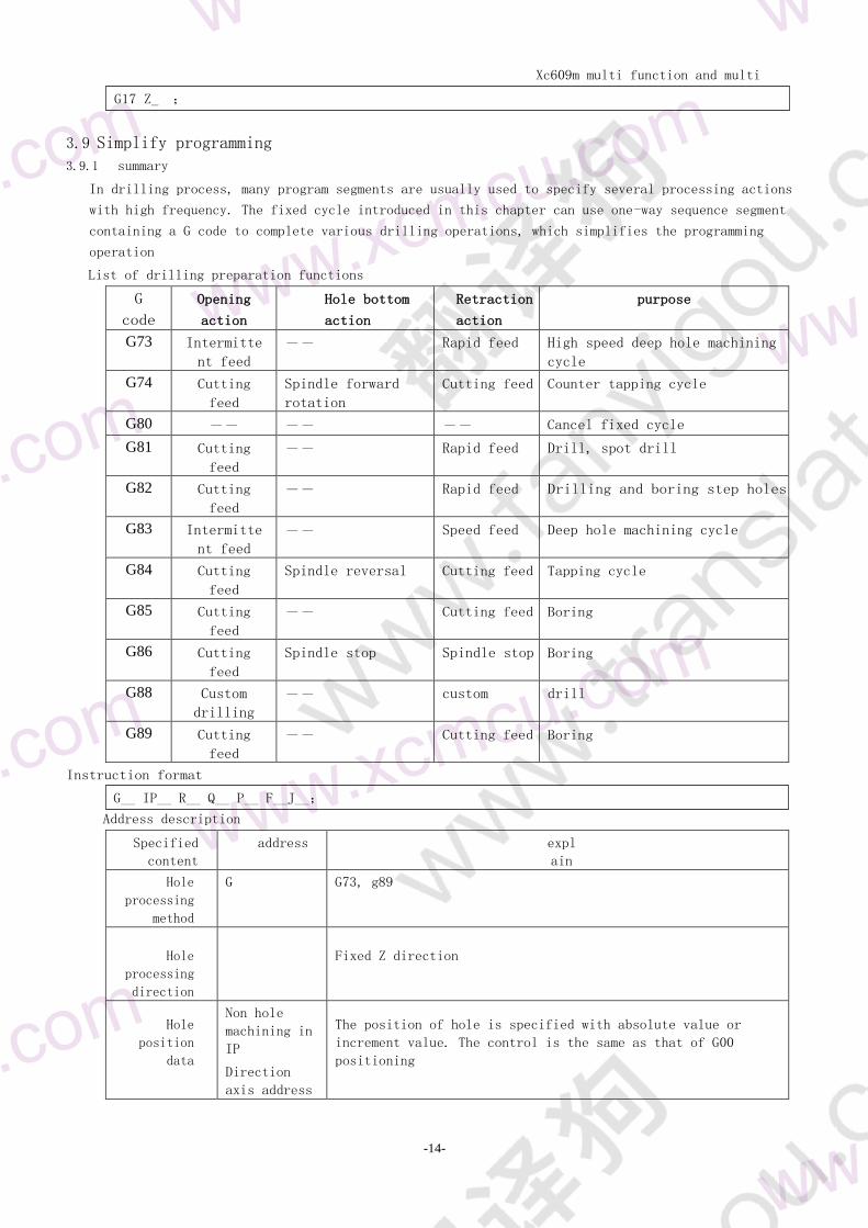
39 Simplify programming 58
391 general 58
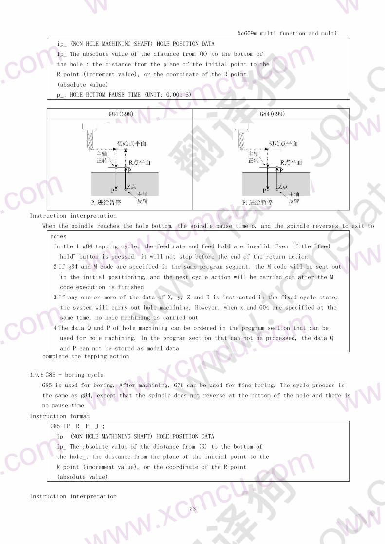
392 G73 - high speed deep hole machining cycle 59
393 G74 - counter tapping cycle 60
394 G81 drilling cycle and spot drilling cycle 60
395 G82 - drilling cycle boring step hole cycle 61
39 DEEP HOLE MACHINING 62
397 G84 - TAPPING CYCLE 62
398 G85 - BORING CYCLE 63
399 G86 - BORING CYCLE 64
3910 G88 - Custom drilling 64
3911 G89 - BORING CYCLE 64
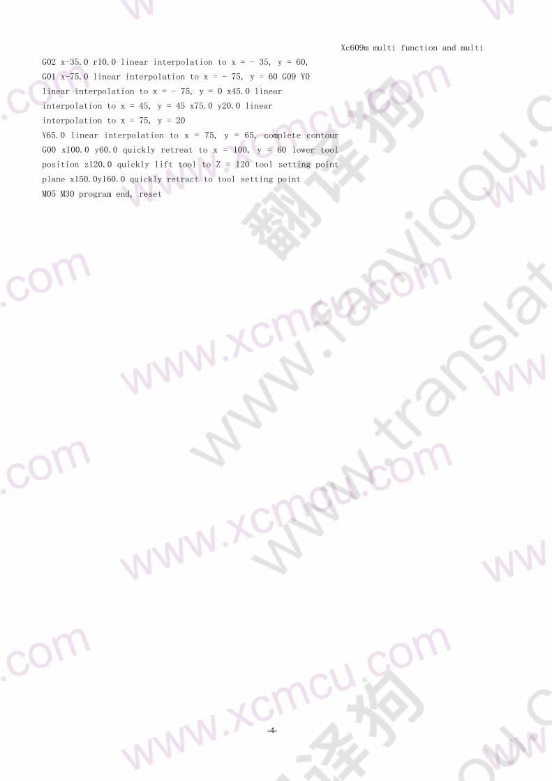
9 65
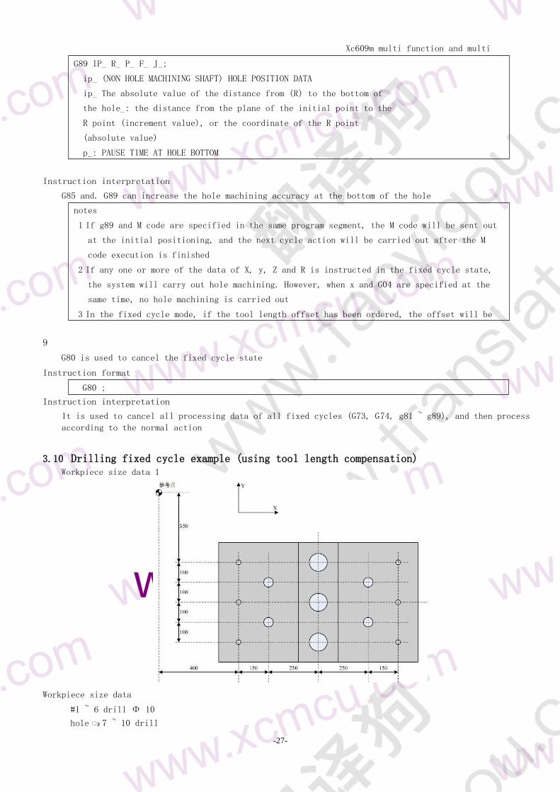
310 Drilling fixed cycle example (using tool length compensation) 65
311 G22-G23 LOOP EXECUTION 67
312 G31 - jumping function 67
Xc609m multi function and multi
purpose CNC System Manual
-6-
13 G50-G51 68
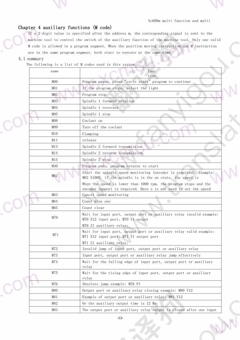
Chapter 4 auxiliary functions (M code) 69
41 overview 69
42 M code description 69
421 M00 - program pause 69
422 M01 - program select Stop 70
423 M02 - end of program 70
424 M03 - spindle 1 forward rotation 70
425 M04 - spindle 1 reverse 70
426 M05 - spindle 1 stop 70
427 M088M09 - COOLANT ON SWITCH 70
428 M100M11 - CLAMP LOOSE 71
429 M13 spindle 2 forward rotation 71
4210 M14 - spindle 2 reverse 71
4211 M15 - spindle 2 stop 71
4212 M30 - program stop 71
4212 M62 - speed monitoring 71
463 M2 - cancel speed monitoring 71
4214 M64 counter plus one 72
4215 M65 - counter clear 72
4216 M70 - wait for input port output port and auxiliary relay to be invalid 72
4216 M71 - wait for input port output port and auxiliary relay to work 72
4217 M72 - invalid jump of input port output port and auxiliary relay 72
4217 M73 relay active jump 72
4218 M74 - waiting for input port output port and falling edge of auxiliary relay 73
4219 M75 wait for input port output port and auxiliary relay to rise 73
4220 M80 output port auxiliary relay off 73
4221 M81 output port auxiliary relay on 73
4222 M82 - output port auxiliary relay output closed for a period of time 74
4223 M83 - output port auxiliary relay output wait for an input port to be valid and then turn off 74
4224 The auxiliary output of M84 is invalid 74
4219 M988M99 - SUBROUTINE CALL AND SUBROUTINE RETURN 74
Chapter 5 tool compensation function (H code) 76
51 tool compensation 76
G5 GZ axis compensation 76
Chapter 6 user macro program 78
61 definition 78
62 variables 78
63 system variables 79
631 Macro signal system variable interface 79
632 Macro variables of tool compensation system 79
633 Other system variables 80
64 Arithmetic and logic 80
65 Transfer and circulation 81
651 Unconditional transfer (goto statement) 81
652 Conditional control (if statement) 81
Xc609m multi function and multi
purpose CNC System Manual
-7-
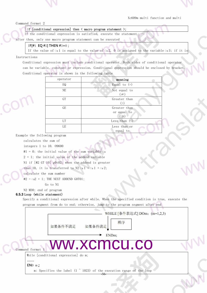
653 Loop (while statement) 82
Chapter 7 integrated routines 84
71 grinder routines 84
72 The realization of no tooth division error by using macro division operation 84
73 Press and feed routine 84
74 3-axis circle bisection drilling 86
75 Three axis rectangular array drilling 87
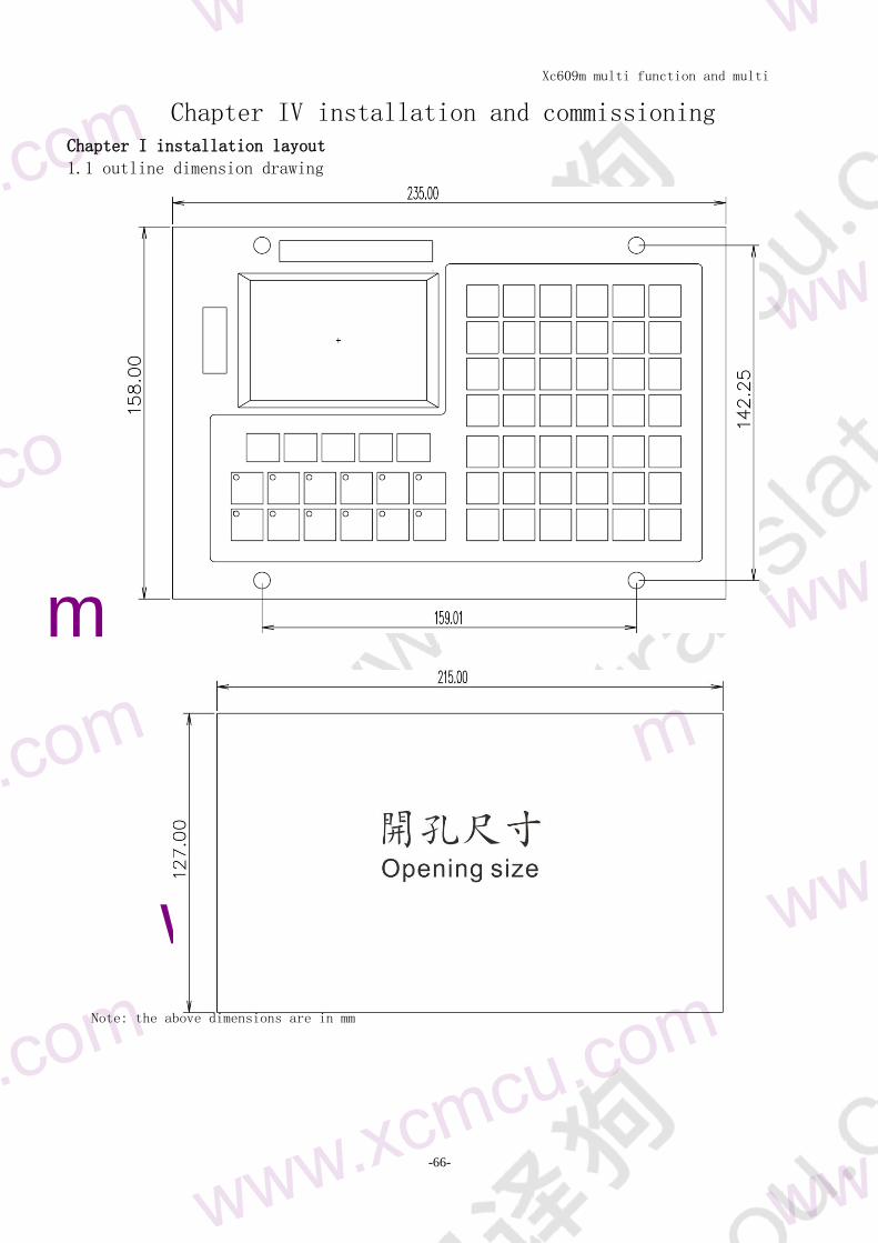
Chapter IV installation and commissioning 88
Chapter I installation layout 88
11 outline dimension drawing 88
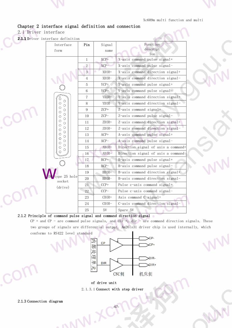
Chapter 2 interface signal definition and connection 89
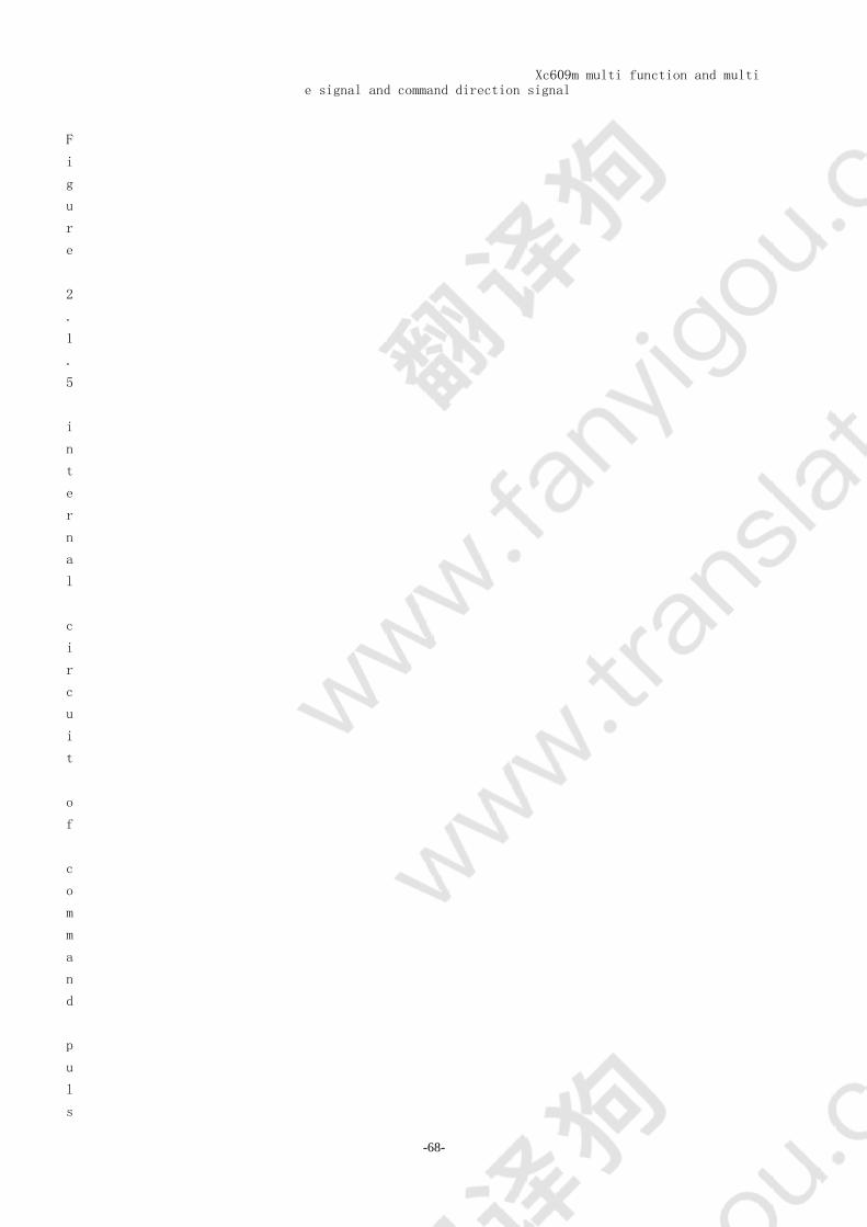
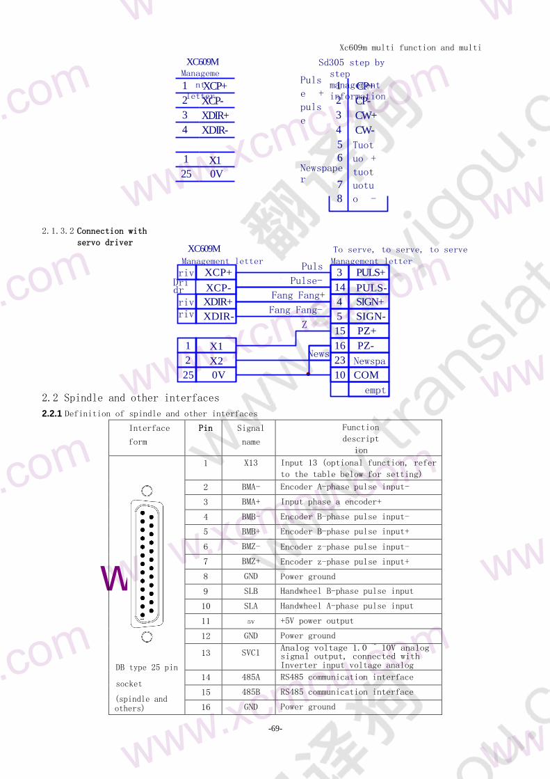
21 driver interface 89
211 Driver interface definition 89
212 Principle of command pulse signal and command direction signal 89
213 Connection diagram of drive unit 89
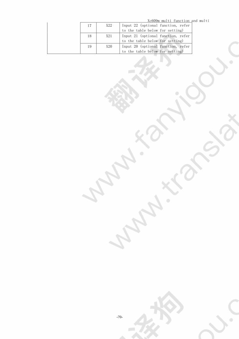
22 Spindle and other interfaces 90
221 Definition of spindle and other interfaces 90
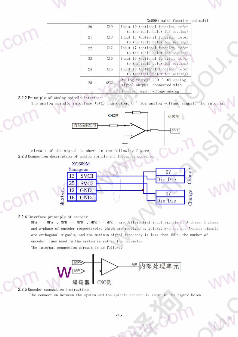
222 Principle of analog spindle interface 91
223 Connection description of analog spindle and frequency converter 91
224 Interface principle of encoder 91
225 Encoder connection instructions 91
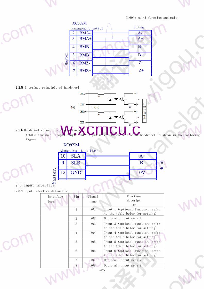
225 Interface principle of handwheel 92
226 Handwheel connection instructions 92
23 input interface 92
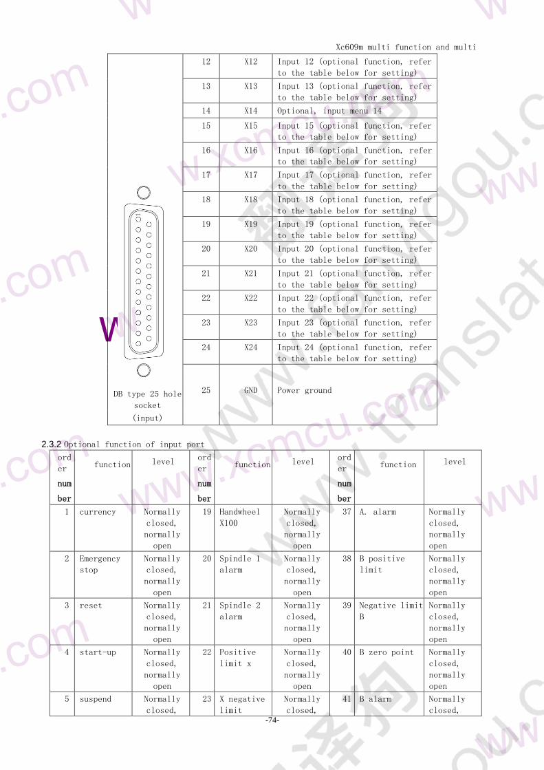
231 Input interface definition 92
232 Optional function of input port 93
233 Principle of input circuit 93
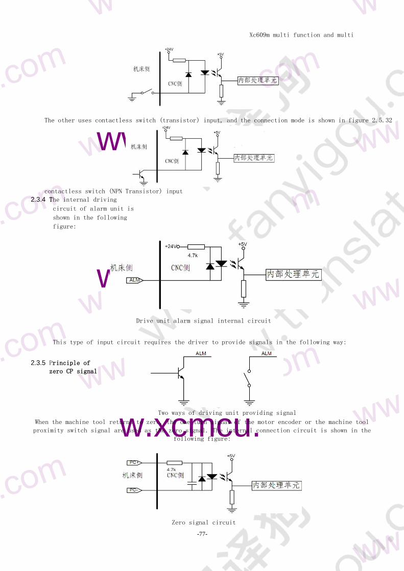
234 ALM principle of driving unit alarm signal 94
235 Principle of zero CP signal 94
24 output interface 95
241 Output interface definition 95
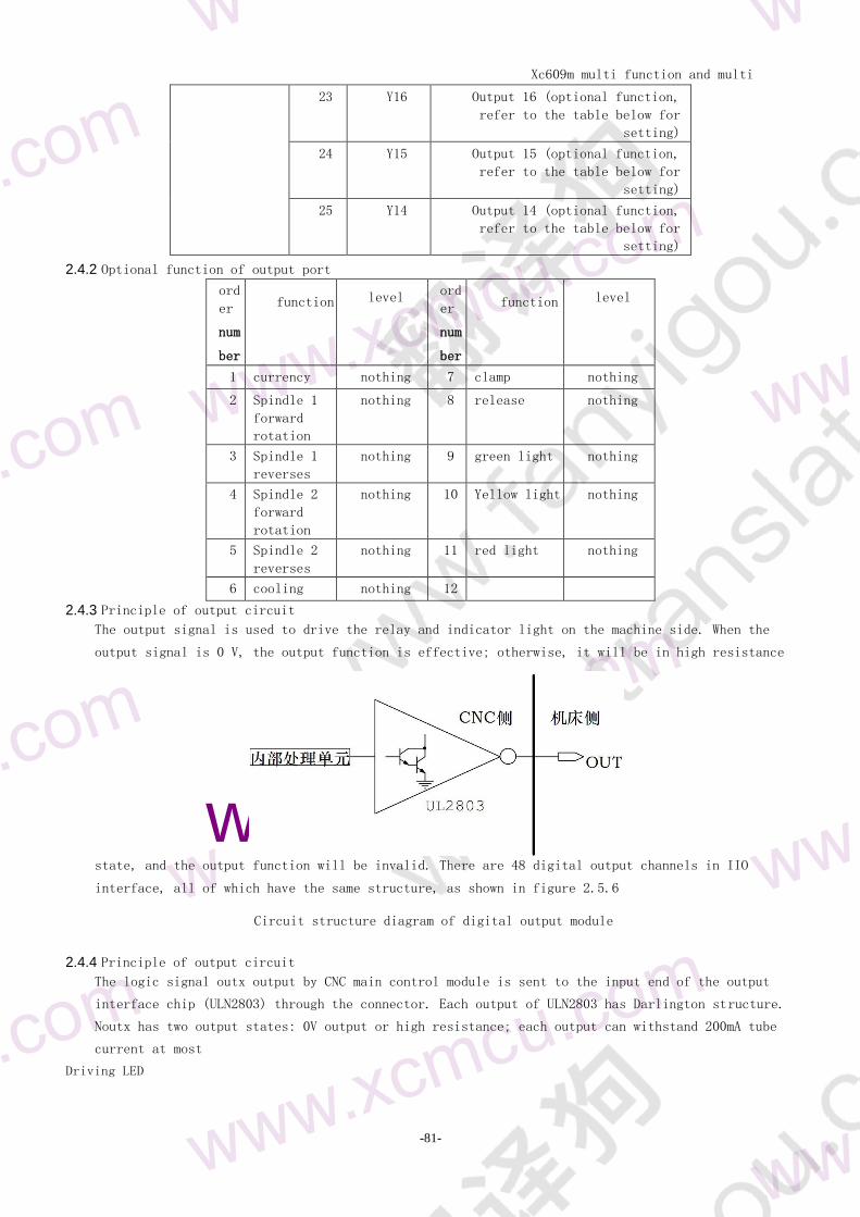
242 Optional function of output port 96
243 Principle of output circuit 96
244 Principle of output circuit 96
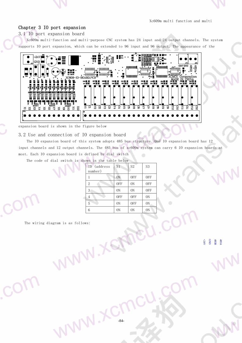
Chapter 3 IO port expansion 98
31 IO port expansion board 98
32 Use and connection of IO expansion board 98
Chapter 5 references 99
The first chapter is the basic method of NC milling machine programming 99
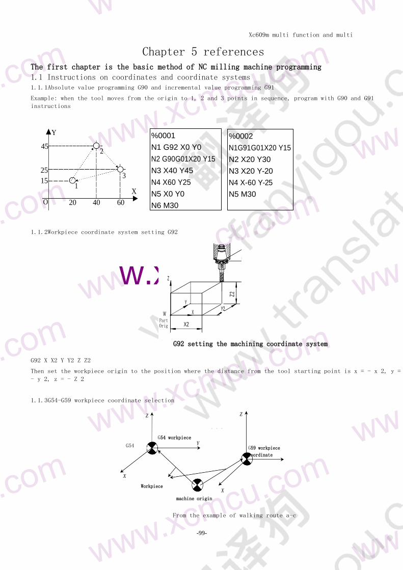
11 Instructions on coordinates and coordinate systems 99
111 Absolute value programming G90 and incremental value programming G91 99
112 Workpiece coordinate system setting G92 99
113 workpiece coordinate system selection G54-G59 99
12 Understanding of coordinate plane 100
13 Circular interpolation instruction 100
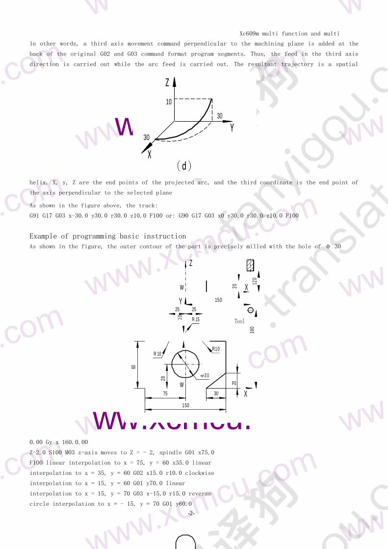
14 Examples of basic instruction programming 102
Xc609m multi function and multi
purpose CNC System Manual
-8-
11 System
introduc
tion
Part 1 System Overview
We developed a CNC system with multi-function multi-function multi-function and multi-function
CNC systemIt is the best choice for CNC drilling machine CNC milling machine special machine tool
automatic equipment automatic welding robot feeding robot coordinate robot etc
Software and hardware characteristics of xc609m CNC system
001m maximum interpolation accuracy of 120 mm
Three programs (one main program and two auxiliary programs) can be run simultaneously which is convenient for
processing loading and unloading
The system is equipped with a 20 inch LCD screen easy to operate and debug
It is compatible with FANUC system instruction
There are 40 kinds of G instructions supporting drilling cycle and tapping cycle
Full screen editing of part program built-in 128M mass program space can store n part programs
With USB interface support u disk file reading and writing data backup
It is convenient to (24) points and can be expanded to (24) points
Operation interface in Chinese and English complete help information more convenient operation
The system adopts pre interpolation acceleration and deceleration control
It supports multi-level operation authority facilitates equipment management and has time limited system
locking function
Support third party software G code file
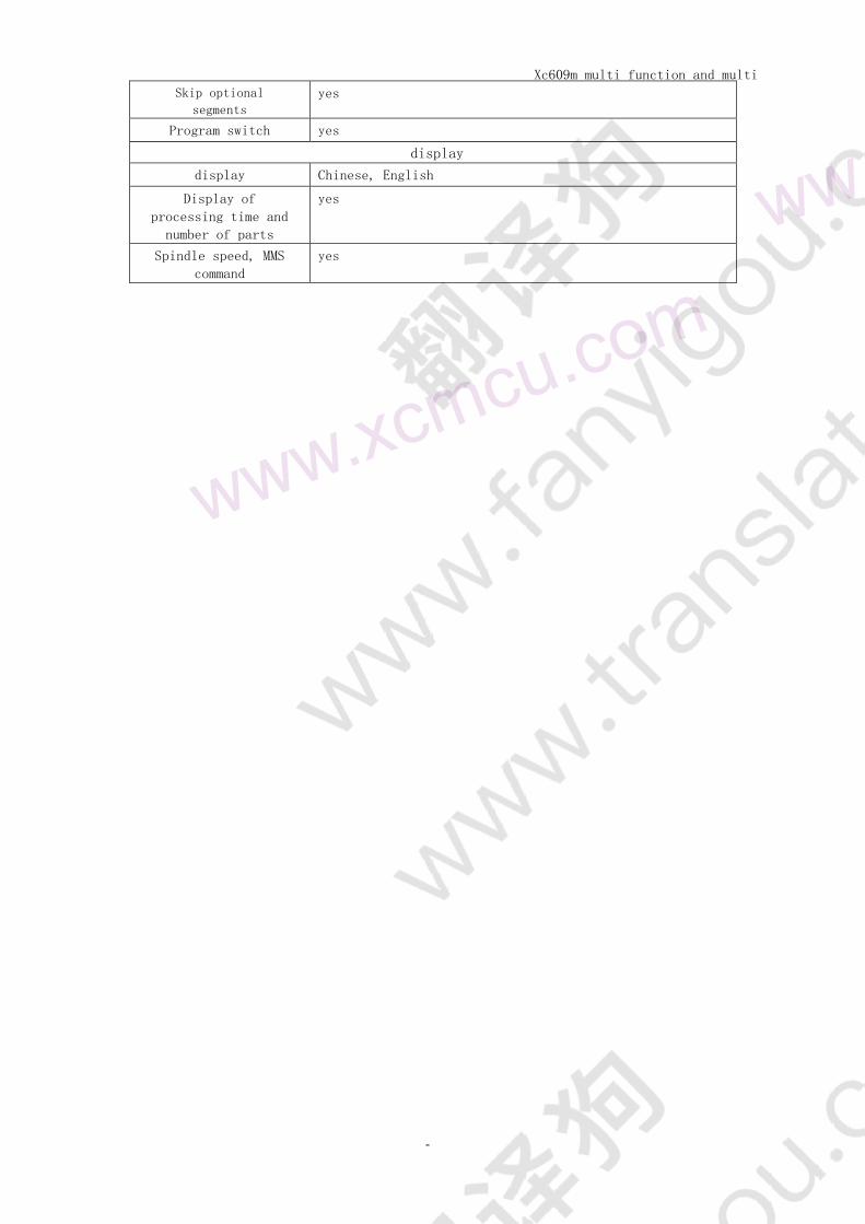
12 technical specifications
basic
function
Axis number control Y Z C Z axis
Number of linkage
axes
Full linkage
Simulation spindle 2
Spindle monitoring yes
Minimum instruction
unit 0001 mm
Maximum instruction
value
plusmn 99999999 times minimum instruction unit
Rapid feed rate 12000 mmm
Rate rapid feed F0 25 50 100
feed rate 12000 mmm
Feed rate multiplier 0~150
Electronic gear
ratio
1~65535 1~65535
Automatic
acceleration and
deceleration
yes
location G00 (linear interpolation)
interpolation Linear interpolation (G01) circular arc interpolation
(g022g033g12) spiral interpolation
Xc609m multi function and multi
purpose CNC System Manual
-9-
Return to reference
point
Automatic return to reference point (G28)
LCD LCD screen 205 tfx3480t
MDI software key Five
Single step feed x1x10x100
communication
interface
U disk interface
External handwheel
interface
yes
IIO interface 24424 (expandable to 96696)
Pause (SEC) yes
Xc609m multi function and multi
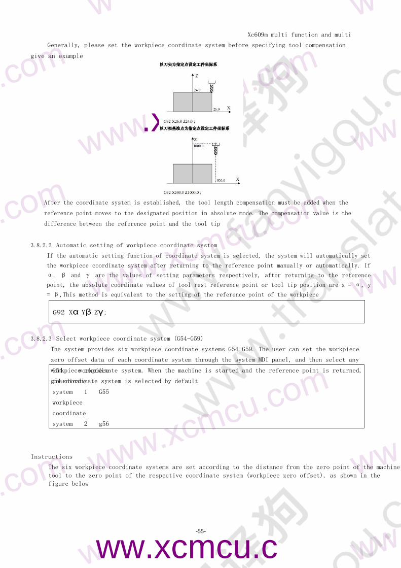
purpose CNC System Manual
-
10
-
Quasi stop state yes
Accurate stop yes
Trip check storage yes
MDI operation Yes it supports multi segment operation
reset yes
Trip switch yes
Single section
operation
yes
Program protection
switch
yes
Self diagnosis
function
yes
Emergency stop yes
Power Supply DC24V
Coordinate system Machine coordinate system (g53) workpiece coordinate system
(G92 g54 ~ G59) local coordinate system
(G52) coordinate system plane assignment
Automatic coordinate
system setting
yes
Decimal point input yes
Auxiliary
function
Auxiliary function M2 digit M code user-defined manual mdii automatic
control spindle rotation reverse
Start and stop control the start and stop of coolant
control the start and stop of lubrication
Spindle
function
Spindle function Double spindle
tapping support
Spindle analog
output
Yes double spindle
Tool
function
Tool function It supports the tool setting in the middle and three-
point centering
Tool compensation
memory
-9999999 ~ 9999999 99
Tool compensation Length compensation of each axis
Edit
operation
Editing function Parameters diagnosis bit input program editing MDI
multi program segment execution
storage capacity 128M
Number of stored
programs
N
Display of program
name
Chinese English numbers combinations
Program line lookup yes
Xc609m multi function and multi
purpose CNC System Manual
-
11
-
Skip optional
segments yes
Program switch yes
display
display Chinese English
Display of
processing time and
number of parts
yes
Spindle speed MMS
command
yes
Xc609m multi function and multi
purpose CNC System Manual
-
12
-
m
w
m
w xcmc
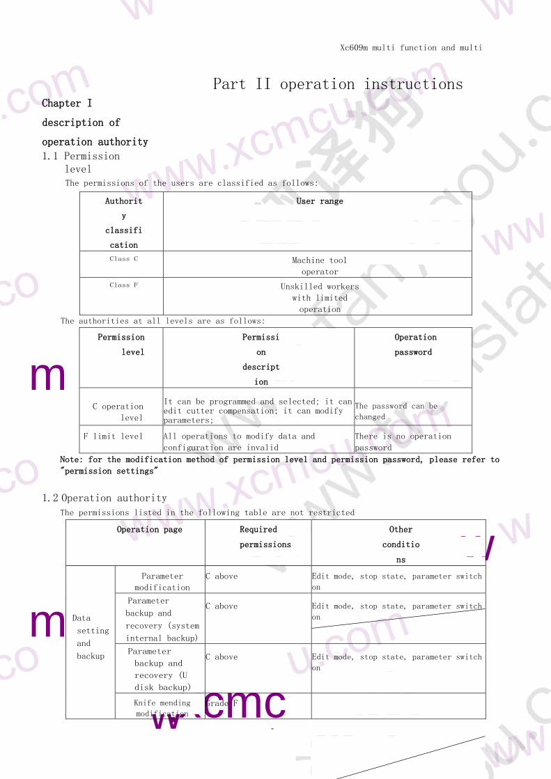
Chapter I
description of
operation authority
11 Permission level
Part II operation instructions
The permissions of the users are classified as follows
Authorit
y
classifi
cation
User range
Class C Machine tool
operator
Class F Unskilled workers
with limited
operation
The authorities at all levels are as follows
Permission
level
Permissi
on
descript
ion
Operation
password
C operation
level
It can be programmed and selected it can edit cutter compensation it can modify parameters
The password can be
changed
F limit level All operations to modify data and
configuration are invalid
There is no operation
password
Note for the modification method of permission level and permission password please refer to
permission settings
12 Operation authority The permissions listed in the following table are not restricted
Operation page Required
permissions
Other
conditio
ns
Data
setting
and
backup
Parameter
modification
C above Edit mode stop state parameter switch
on
Parameter
backup and
recovery (system
internal backup)
C above Edit mode stop state parameter switch
on
Parameter
backup and
recovery (U
disk backup)
C above Edit mode stop state parameter switch
on
Knife mending
modification Grade F
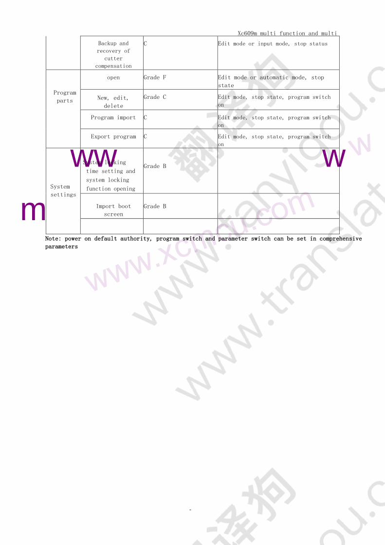
Xc609m multi function and multi
purpose CNC System Manual
-
13
-
ww w
m
Backup and
recovery of
cutter
compensation
C Edit mode or input mode stop status
Program
parts
open Grade F Edit mode or automatic mode stop
state
New edit
delete
Grade C Edit mode stop state program switch
on
Program import C Edit mode stop state program switch
on
Export program C Edit mode stop state program switch
on
System
settings
System locking
time setting and
system locking
function opening
Grade B
Import boot
screen
Grade B
Note power on default authority program switch and parameter switch can be set in comprehensive
parameters
Xc609m multi function and multi
purpose CNC System Manual
-14-
m
wwwxcmcucom w
m
wwwxcmcucom
wwxcmcu
Chapter 2 interface setting
21 panel
Xc609m multi function and multi
purpose CNC System Manual
-15-
m
w
com
211 explain
The upper part is character number editing key
The lower part is the edit and axis selection keys In the edit input hand-held handwheel mode the axis
selection key is invalid In the zero return single handwheel manual mode the edit key is invalid
212 Character number edit key
Character number editing includes all numbers and letters as well as [reset] [backspace] [delete]
[Cancel] [Enter] [upgrade]
Insert modify cursor and page keys
Key Icon Key name Function
al use
Reset key
CNC reset program end processing release alarm
terminate input and output
Backspace
key
delete
Delete the character after the cursor position delete
key to delete the character in front of the cursor
Insert
modify key
Modify edit mode switch between insert and modify mode
or modify data by parameter
escape key
Cancel the input and close the pop-up dialog box to return to
the program content screen
enter key
Confirm the input and close the pop-up dialog box return
to the program content screen At the same time the
specific program section terminator function and line
feed function
shift
Select or cancel the shift up function
Symbol key
In editing mode input special characters such as + -
Page up and
page down
Or click up or down to enter
(shared with axis function key page turning in editing
and entry mode and axis selection key in other modes)
Up down
left and
right
Move the cursor up down left and right (shared with the
axis function key it is flipped in edit and input mode
Cursor keys Page axis selection key in other modes)
Xc609m multi function and multi
purpose CNC System Manual
-16-
w
m
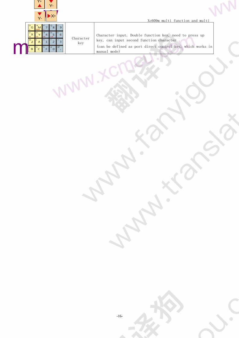
Character
key
Character input Double function key need to press up
key can input second function character
(can be defined as port direct control key which works in
manual mode)
Xc609m multi function and multi
purpose CNC System Manual
-17-
om
wwwxcmcucom
m
w
m
w
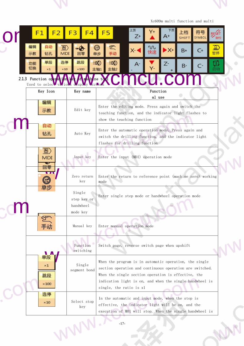
213 Function operation key of machine tool
Used to select various display screens
Key Icon Key name Function
al use
Edit key
Enter the editing mode Press again and switch the
teaching function and the indicator light flashes to
show the teaching function
Auto Key
Enter the automatic operation mode Press again and
switch the drilling function and the indicator light
flashes for drilling function
Input key
Enter the input (MDI) operation mode
Zero return
key
Enter the return to reference point (machine zero) working
mode
Single
step key or
handwheel
mode key
Enter single step mode or handwheel operation mode
Manual key
Enter manual operation mode
Function
switching
Switch page reverse switch page when upshift
Single
segment bond
When the program is in automatic operation the single
section operation and continuous operation are switched
When the single section operation is effective the
indication light is on and when the single handwheel is
single the ratio is x1
Select stop
key
In the automatic and input mode when the stop is
effective the indicator light will be on and the
execution of M01 will stop When the single handwheel is
Xc609m multi function and multi
purpose CNC System Manual
-18-
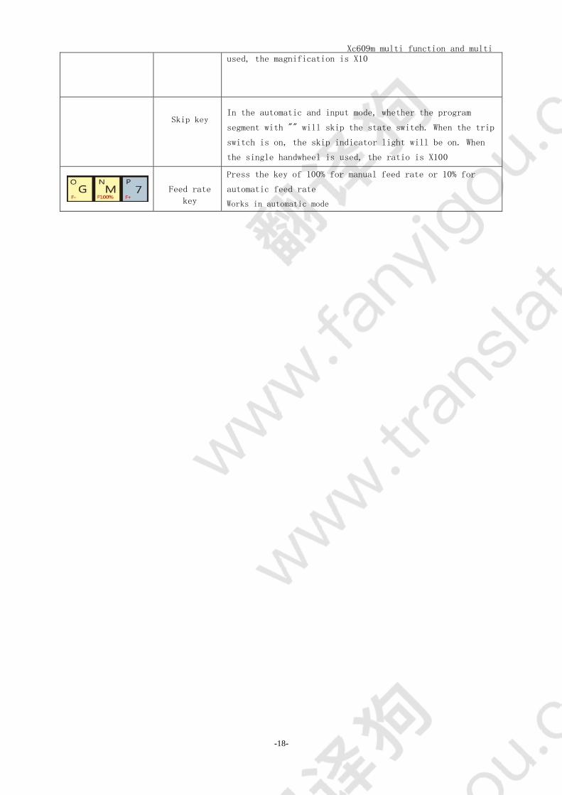
used the magnification is X10
Skip key
In the automatic and input mode whether the program
segment with will skip the state switch When the trip
switch is on the skip indicator light will be on When
the single handwheel is used the ratio is X100
Feed rate
key
Press the key of 100 for manual feed rate or 10 for
automatic feed rate
Works in automatic mode
Xc609m multi function and multi
purpose CNC System Manual
-19-
m
w
m
w
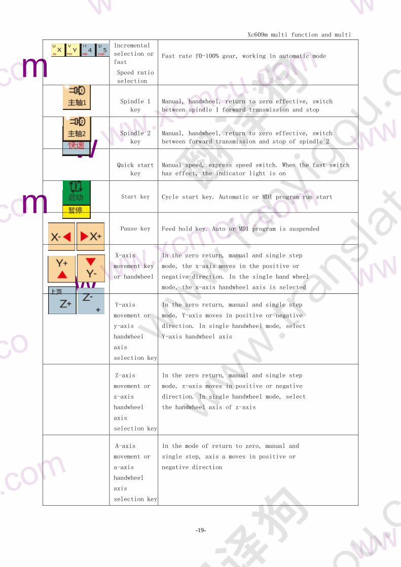
Incremental
selection or
fast
Speed ratio
selection
Fast rate f0-100 gear working in automatic mode
Spindle 1
key
Manual handwheel return to zero effective switch
between spindle 1 forward transmission and stop
Spindle 2
key
Manual handwheel return to zero effective switch
between forward transmission and stop of spindle 2
Quick start
key
Manual speed express speed switch When the fast switch
has effect the indicator light is on
Start key
Cycle start key Automatic or MDI program run start
Pause key
Feed hold key Auto or MDI program is suspended
X-axis
movement key
or handwheel
In the zero return manual and single step
mode the x-axis moves in the positive or
negative direction In the single hand wheel
mode the x-axis handwheel axis is selected
Y-axis
movement or
y-axis
handwheel
axis
selection key
In the zero return manual and single step
mode Y-axis moves in positive or negative
direction In single handwheel mode select
Y-axis handwheel axis
Z-axis
movement or
z-axis
handwheel
axis
selection key
In the zero return manual and single step
mode z-axis moves in positive or negative
direction In single handwheel mode select
the handwheel axis of z-axis
A-axis
movement or
a-axis
handwheel
axis
selection key
In the mode of return to zero manual and
single step axis a moves in positive or
negative direction
Xc609m multi function and multi
purpose CNC System Manual
-20-
m
w
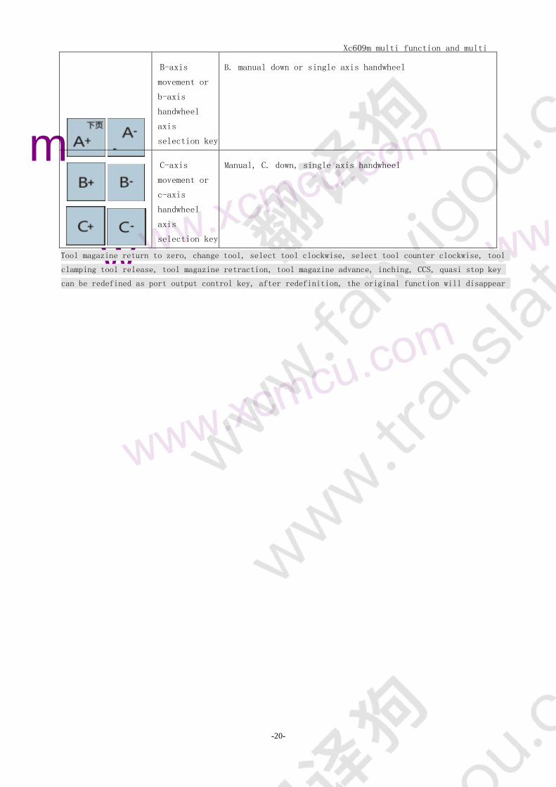
B-axis
movement or
b-axis
handwheel
axis
selection key
B manual down or single axis handwheel
C-axis
movement or
c-axis
handwheel
axis
selection key
Manual C down single axis handwheel
Tool magazine return to zero change tool select tool clockwise select tool counter clockwise tool
clamping tool release tool magazine retraction tool magazine advance inching CCS quasi stop key
can be redefined as port output control key after redefinition the original function will disappear
Xc609m multi function and multi
purpose CNC System Manual
-21-
w
wwxcmcuc
22 Page display
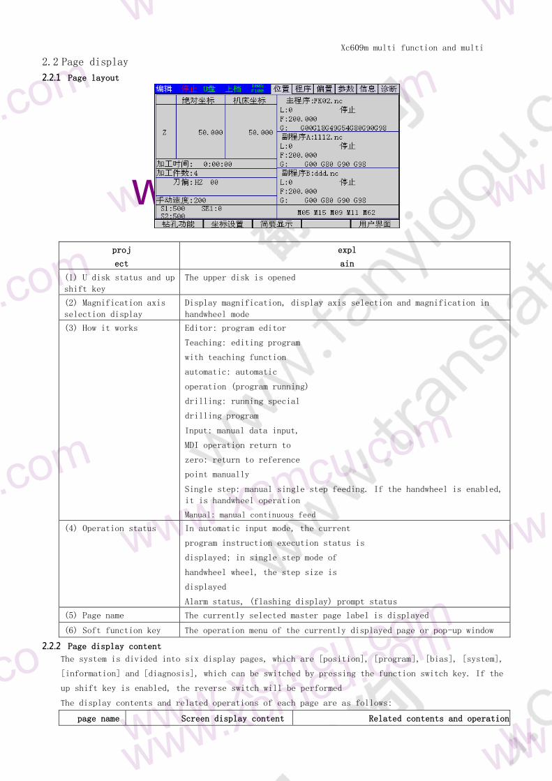
221 Page layout
proj
ect
expl
ain
(1) U disk status and up
shift key
The upper disk is opened
(2) Magnification axis
selection display
Display magnification display axis selection and magnification in
handwheel mode
(3) How it works Editor program editor
Teaching editing program
with teaching function
automatic automatic
operation (program running)
drilling running special
drilling program
Input manual data input
MDI operation return to
zero return to reference
point manually
Single step manual single step feeding If the handwheel is enabled
it is handwheel operation
Manual manual continuous feed
(4) Operation status In automatic input mode the current
program instruction execution status is
displayed in single step mode of
handwheel wheel the step size is
displayed
Alarm status (flashing display) prompt status
(5) Page name The currently selected master page label is displayed
(6) Soft function key The operation menu of the currently displayed page or pop-up window
222 Page display content
The system is divided into six display pages which are [position] [program] [bias] [system]
[information] and [diagnosis] which can be switched by pressing the function switch key If the
up shift key is enabled the reverse switch will be performed
The display contents and related operations of each page are as follows
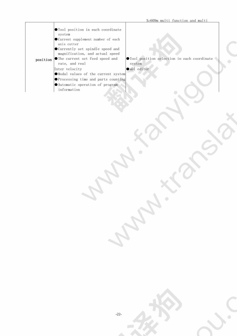
page name Screen display content Related contents and operation
Xc609m multi function and multi
purpose CNC System Manual
-22-
Tool position in each coordinate
system
Current supplement number of each
axis cutter
Currently set spindle speed and
magnification and actual speed
position The current set feed speed and
rate and real
Inter velocity
Tool position selection in each coordinate
system
MDI editor Modal values of the current system
Processing time and parts counting
Automatic operation of program
information
Xc609m multi function and multi
purpose CNC System Manual
-23-
m
w wwxc w
m
program
Currently open CNC machining
program
Program directory
Processing program editing
Copy and delete machining program files in
program directory (including local and U disk)
The input and output files of different
processing programs are stored in memory
bias
Offset tool Set the length in each direction
parameter
system parameter
Logical parameters
Advanced operations
Parameter setting
Logical parameter setting
informatio
n
CNC alarms currently occurring
system information
Alarm viewing and clearing
Permission setting
System lock settings
Parameter switch and program switch
diagnosis CNC related diagnostic information Search by serial number
223 Soft function key menu
Each main page is switched to each sub screen through soft function key The function of soft function key
is triggered by the users pressing and lifting action According to the operation mode the
classification is as follows
A In page operation not highlighted
B Enter the next submenu
C Page display options or display content switching
D Pop up window
Xc609m multi function and multi
purpose CNC System Manual
-24-
wwxcmcuco
wwxcmcuco
23 Location screen
231 Picture composition
The position main interface displays coordinates processing time number of pieces processed
tool offset number of each axis manual speed spindle speed operation information of each program
and some mode m codes
Speed setting of spindle ses2 1
232 Drilling function setting screen
Press the soft function key [drilling function] on the position main page to switch to the drilling page
This page displays the data of drilling function as shown in the figure
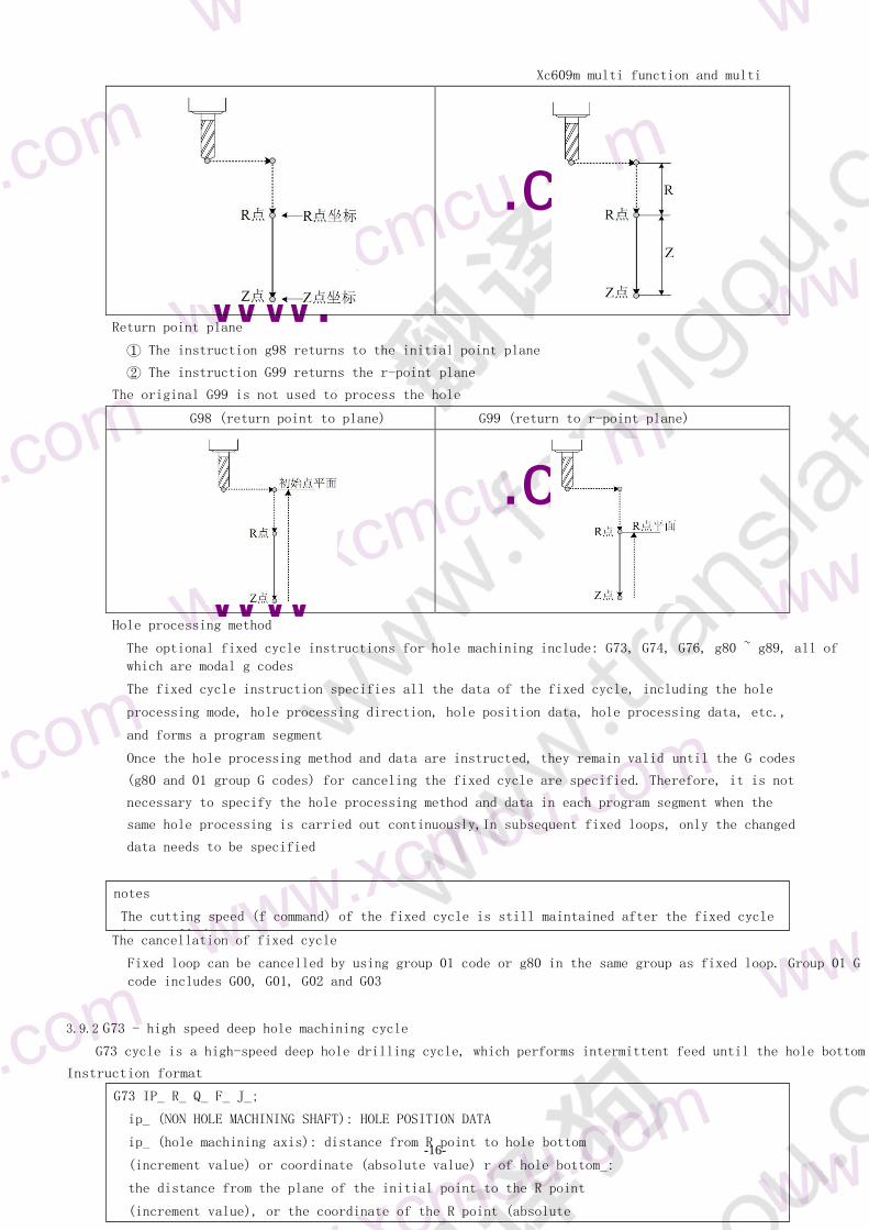
Explanations
Drilling instruction select the fixed cycle instruction required for drilling
Q D the D data in the fixed cycle will be ignored and the data of drilling
parameters will be used with the drilling function D the D data in the fixed
cycle the D data in the parameter will be ignored and the data of the
drilling parameters will be used D the delay P (MS) in the fixed cycle
Hole depth drilling depth absolute coordinates are used in special drilling R
(drilling start) plane is fixed at 0 and drilling axis is fixed on Z axis
Drilling speed F processing speed during drilling
Xc609m multi function and multi
purpose CNC System Manual
-25-
Spindle speed s the spindle speed when drilling
note refers to the speed of spindle 1 Automatic
clamping whether to clamp before drilling
Safe height the height of z-axis when drilling multiple holes
End in place stop position of each axis after drilling all holes If it is multi axis return to Z axis first
and then other axes
Xc609m multi function and multi
purpose CNC System Manual
-26-
wwxcmcuc
wwwxcmcuco
Cooling on whether to turn on cooling
Stop spindle stop spindle 1 after drilling
Current hole number the current number of holes in multi axis
which can be modified at stop and start from current hole
Machining count Statistics of workpiece quantity
233 G88 editing
Press the [G88 edit] soft function key to switch to this screen G88 is the special drilling instruction of the
controller which can specify the drilling section section speed and minute
The speed of each section is 20 segments in total and the chip removal is as shown in the figure
Depth the depth of each segment Note that it is an absolute value If 0 is encountered the
depth specified by the program will end after the end If the hole depth is greater than the
depth specified in the program or drilling function the depth specified in the program or
drilling function will be used
Speed the speed of each segment If it is 0 then the speed specified by the program
Speed refers to the speed of spindle 1 which can not be controlled by
spindle 2 If it is 0 the speed specified in the program in this
section Chip removal chip removal in the given way
Depth reading can read the current absolute value coordinates of Z axis
234 Multi hole editing
If it is a multi axis controller (larger than one axis) press [multi hole edit] to enter this page
Figure 234 coordinate system screen
This function can be set for multi hole
Xc609m multi function and multi
purpose CNC System Manual
-27-
machining The number of holes can reach
9999 The drilling axis is Z axis and
the other is non machining axis
All coordinates are absolute
If it is not the first hole if the non machining axis data is all 0
then the processing ignores the later data and the processing is
finished That is to say the non machining coordinates of the first
hole can be all 0 and other holes cannot be all 0
Xc609m multi function and multi
purpose CNC System Manual
-28-
wwwxcmcuco
wwwxcmcuco
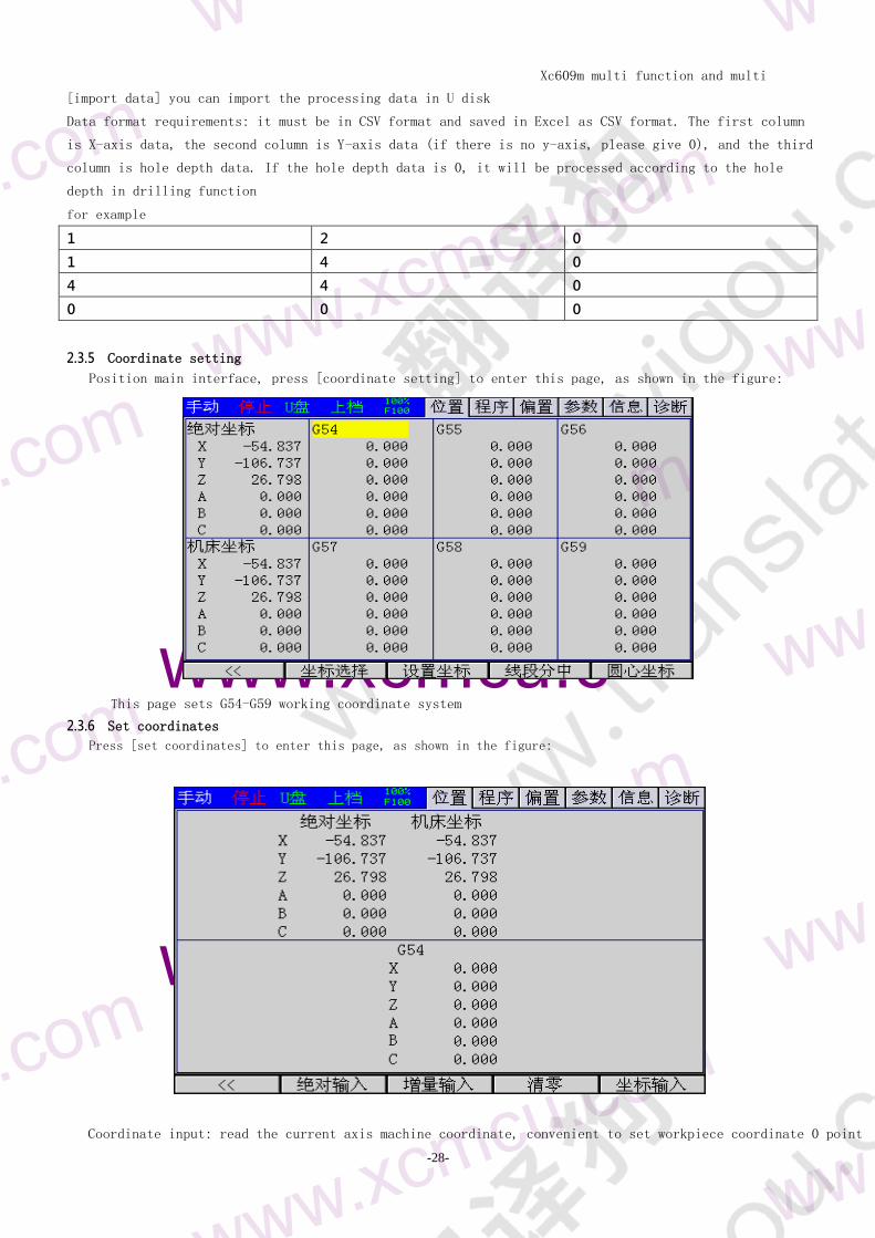
[import data] you can import the processing data in U disk
Data format requirements it must be in CSV format and saved in Excel as CSV format The first column
is X-axis data the second column is Y-axis data (if there is no y-axis please give 0) and the third
column is hole depth data If the hole depth data is 0 it will be processed according to the hole
depth in drilling function
for example
1 2 0
1 4 0
4 4 0
0 0 0
235 Coordinate setting
Position main interface press [coordinate setting] to enter this page as shown in the figure
This page sets G54-G59 working coordinate system
236 Set coordinates
Press [set coordinates] to enter this page as shown in the figure
Coordinate input read the current axis machine coordinate convenient to set workpiece coordinate 0 point
Xc609m multi function and multi
purpose CNC System Manual
-29-
237 Line segmentation
If it is a multi axis system (larger than one axis) press [segment division] to enter this page as shown in
the figure
Xc609m multi function and multi
purpose CNC System Manual
-30-
wwxcmcuc
wwxcmcuc
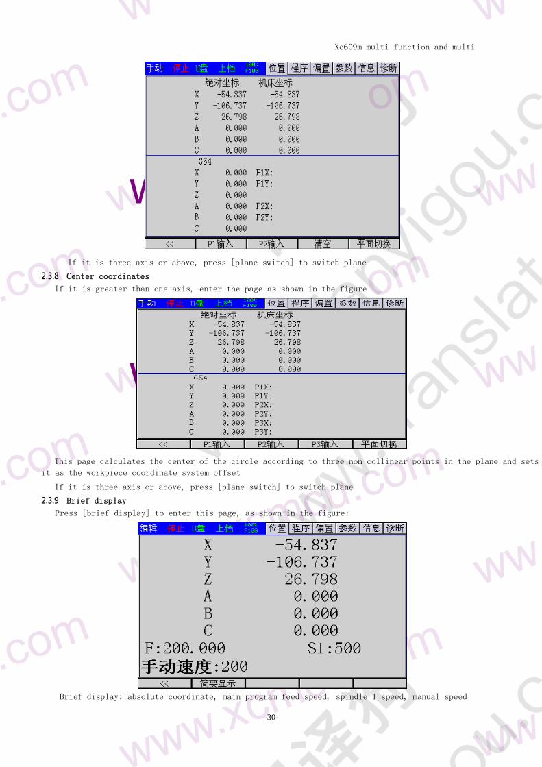
If it is three axis or above press [plane switch] to switch plane
238 Center coordinates
If it is greater than one axis enter the page as shown in the figure
This page calculates the center of the circle according to three non collinear points in the plane and sets
it as the workpiece coordinate system offset
If it is three axis or above press [plane switch] to switch plane
239 Brief display
Press [brief display] to enter this page as shown in the figure
Brief display absolute coordinate main program feed speed spindle 1 speed manual speed
Xc609m multi function and multi
purpose CNC System Manual
-31-
wwxcmcuc
wwxcmcuc
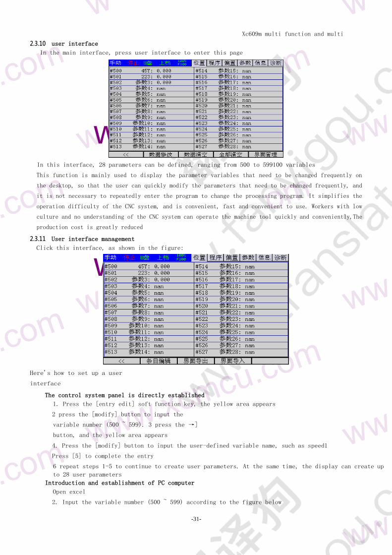
2310 user interface
In the main interface press user interface to enter this page
In this interface 28 parameters can be defined ranging from 500 to 599100 variables
This function is mainly used to display the parameter variables that need to be changed frequently on
the desktop so that the user can quickly modify the parameters that need to be changed frequently and
it is not necessary to repeatedly enter the program to change the processing program It simplifies the
operation difficulty of the CNC system and is convenient fast and convenient to use Workers with low
culture and no understanding of the CNC system can operate the machine tool quickly and convenientlyThe
production cost is greatly reduced
2311 User interface management
Click this interface as shown in the figure
Heres how to set up a user
interface
The control system panel is directly established
1 Press the [entry edit] soft function key the yellow area appears
2 press the [modify] button to input the
variable number (500 ~ 599) 3 press the rarr]
button and the yellow area appears
4 Press the [modify] button to input the user-defined variable name such as speed1
Press [5] to complete the entry
6 repeat steps 1-5 to continue to create user parameters At the same time the display can create up
to 28 user parameters
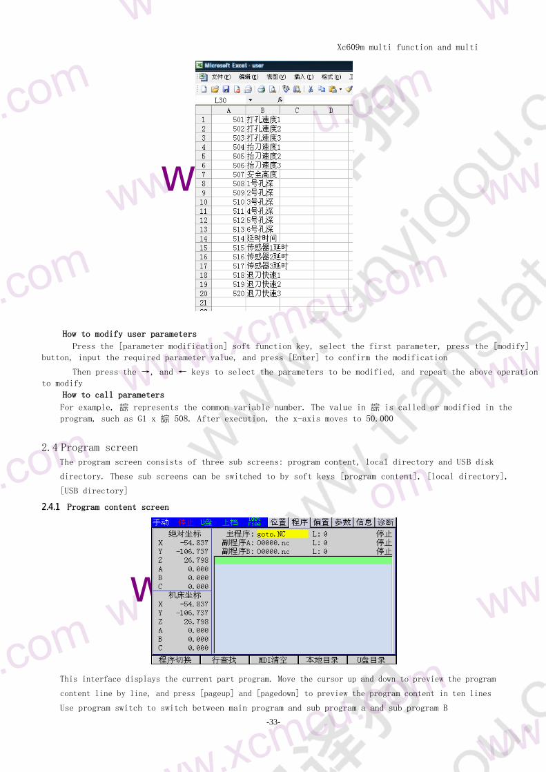
Introduction and establishment of PC computer
Open excel
2 Input the variable number (500 ~ 599) according to the figure below
Xc609m multi function and multi
purpose CNC System Manual
-32-
3 Input the user-defined variable name such as safe height and hole depth
4 Save it as a CSV file with the file name of usercsv
5 copy into U disk Insert control system USB socket
6 In the user interface screen press the [interface import] soft function key to select the path and
file name Press the [Enter] button
7 User interface established successfully
Xc609m multi function and multi
purpose CNC System Manual
-33-
wxcmc
wwxcmcuc
How to modify user parameters
Press the [parameter modification] soft function key select the first parameter press the [modify]
button input the required parameter value and press [Enter] to confirm the modification
Then press the rarr and larr keys to select the parameters to be modified and repeat the above operation
to modify
How to call parameters
For example 誴 represents the common variable number The value in 誴 is called or modified in the
program such as G1 x 誴 508 After execution the x-axis moves to 50000
24 Program screen
The program screen consists of three sub screens program content local directory and USB disk
directory These sub screens can be switched to by soft keys [program content] [local directory]
[USB directory]
241 Program content screen
This interface displays the current part program Move the cursor up and down to preview the program
content line by line and press [pageup] and [pagedown] to preview the program content in ten lines
Use program switch to switch between main program and sub program a and sub program B
Xc609m multi function and multi
purpose CNC System Manual
-34-
wwxcmcuc
wwxcmcuc
m
w
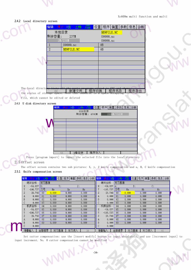
242 Local directory screen
The local directory lists all the parts programs stored in CNC and shows
the status of storage space Note that o0000nc is a space occupying
file which cannot be edited or deleted
243 U disk directory screen
Press [program import] to import the selected file into the local directory
25 Offset screen
The offset screen contains two sub pictures X y Z knife compensation and a B C knife compensation
251 Knife compensation screen
Set cutter compensation use the [insert modify] button to input absolutely and use [increment input] to
input increment No 0 cutter compensation cannot be modified
Xc609m multi function and multi
purpose CNC System Manual
-35-
wwxcmcuc
wwxcmcuc
Tool setting method take a tool as the reference move the tool tip to a reference point press [tool
setting reference] for axis selection input the selected axis machine tool coordinate to the reference
coordinate then change the target tool move the tool tip to the reference point manually or by hand
wheel press [tool setting read in] to select positive and negative (because positive and negative tool
compensation cannot be specified except for Z axis) If the tool is parallel to tool setting axis use
positive direction such as Z axisIf it is perpendicular to the tool setting axis use negative direction
The system will automatically calculate the difference between the length of the tool and the reference
tool and store it in the corresponding tool complement number
26 Parameter screen The parameter screen includes comprehensive parameters input port configuration output port
configuration direct control function configuration and axis parameter These sub screens can be switched
to by soft key
261 Parameter synthesis screen
Comprehensive parameters are used to set system related parameters With notes they can be easily
modified
Note the position units in the parameters are all 0001 for
example G73 tool withdrawal 1000 stands for 1mm In editing
mode use the [modify] key to set
262 Input port parameter screen
The input port parameters are used to set the function parameters of the input port
1 ~ 48 input ports can be configured as buttons limit alarm handwheel axis selection and other
Xc609m multi function and multi
purpose CNC System Manual
-36-
functions 25 ~ 48 are expansion input ports and the speed of the extended input ports is slow
Please do not configure the limit alarm and other functions that need to be detected in time In the
editing mode use the [modify] key to set
The input port can also be configured with the [modify] key in the diagnosis function
263 Output parameter screen
The output parameters are used to set the function parameters of the output port They are annotated and
can be modified conveniently and quickly
Xc609m multi function and multi
purpose CNC System Manual
-37-
wwxcmcuc
wwxcmcuc
wwxcmcuco
The output port can be configured as spindle cooling clamping spindle
forward rotation and reverse rotation signal state tricolor lamp which
is convenient for programming
The output port can also be configured with the [modify] key in the
diagnosis function and the test port is more intuitive after the line is
connected 263 direct control parameter screen
Direct control configuration can be configured to directly control the output port in manual mode
The trigger source can be a key or an input port The trigger mode can be self-locking and inching
In edit mode use the [modify] key to set
264 Axis parameter screen
The axis parameter configures the electronic gear and speed of each shaft
Electronic gear numerator number of motor pulses per cycle if there is reducer multiplied by reduction
ratio
Xc609m multi function and multi
purpose CNC System Manual
-38-
Denominator the distance of each turn If it is a screw it is the screw pitch in micrometer
(0001 mm)
Example stepper motor subdivision 16 reducer 51 screw pitch 5mm
16000 200 = 16
Xc609m multi function and multi
purpose CNC System Manual
-39-
wwxcmcuc
wwxcmcuc
Denominator = 5000
The denominator can not be divided into denominators
If the motor has no speed limit the maximum shaft speed can be obtained and the maximum speed of the
controller is 200 kHz
Maximum speed = 200000016000 5 mmms = 625mmms = 625 60mmmmin = 3750mmmmin
In fact the motor speed exceeds the maximum effective speed of the stepper motor which should
be subject to the maximum effective speed of the stepper motor Assuming that the maximum effective
speed of the stepper motor is 800 rpm the maximum speed is 80005 5 = 800mmmin
27 Information screen The parameter screen consists of three sub screens alarm information and system information
which can be switched to by soft keys [alarm information] and [system information]
271 Alarm information screen
The alarm information screen displays the list of current alarms Each alarm message contains the
alarm number and alarm content The alarm content briefly describes the alarm and its release
method
There are two alarm types when CNC alarm occurs the program operation is stopped different
alarm clearing methods are different some alarms are cleared by pressing [reset] some alarms
can be cleared only by restarting the system Please refer to the description document of alarm
information for details
Boot screen import a set of true color bmp format screen with size less than or equal to 480 320
should be made and saved as startbmp stored in the root directory of U disk insert the controller
press [import boot screen] wait for the prompt to import successfully If the prompt fails please
confirm whether the name of boot screen is correct
272 System information screen
Xc609m multi function and multi
purpose CNC System Manual
-40-
According to the parameter switch and program switch switch the switch state Set the authority and set
the corresponding authority The F level does not need a password The default password of level C and B is
888888
Password is needed from low to high but no password is needed from high to low If the password
of level C is forgotten you can go to level B first and then lower to level C and then modify
the password of level C
The permissions from low to high are f level C level and B level
Xc609m multi function and multi
purpose CNC System Manual
-41-
wwxcmcuc
wwxcmcuc
273 Password and change time screen
Set the total power on running time according to the trial time and set 0 to cancel the restriction The
contact phone is used to contact the seller after the time is expired
The above level B permission is required After setting the trial time you must change the password of level B
permission Please remember that the manufacturer cannot unlock the level B password
Password modification is used to modify the authority password of this level To modify the password you
need to input the same password twice The password can be composed of numbers and letters with a maximum of
11 digits
28 Diagnosis screen The diagnosis screen consists of 6 sub screens input diagnosis output diagnosis local variable common
variable 1 and common variable 2
[output diagnosis] [local variable] [common variable 1] [common variable 2] can be switched to these
sub screens
281 Input diagnosis screen
As shown in the figure below when the external input signal is valid the circle of corresponding input
point (in01-in96) will be filled and displayed and the port function name is below the port number
In edit mode press modify to set the function of input port
282 Output diagnosis screen
[output switch] and [all off] the corresponding output points (out01-out96) can be tested When
opened the circle will be filled with the display and the load of the corresponding port will be
opened The port function name is below the
Xc609m multi function and multi
purpose CNC System Manual
-42-
wwxcmcuco
wwxcmcuco
283 Auxiliary relay diagnosis screen
Auxiliary relays (z01 ~ z96) have no physical input and output but they can be used as marker bits for
communication between main and auxiliary programs and for flag bits in programs
29 Macro variable screen Macro value and macro value of macro variables can be set in the macro screen
291 Local variable screen
As shown in the figure below the local variable quantum screen displays the values of
ා ා ා ා ා ා ා ා ා ා ා ා ා ා 353535ා ා ා 353535353535353535ා 353535353535谻 099) These variables are local and each main and
auxiliary programs have their own local variables
Operation steps
1 Move the cursor to select the
required variable number 2 press the
[modify] soft function key to input
the required value
Press enter to confirm the modification If you dont want to modify press cancel to return
Xc609m multi function and multi
purpose CNC System Manual
-43-
wwxcmcuco
wwxcmcuc
wwxcmcuco
The local variables are cleared every time the program starts to run Press the [F2] key to switch to
display the local variables in the main and auxiliary programs
292 Common variable 1 screen
As shown in the figure below the sub screen of common variable 1 displays the values of macro
variables no100-199 These variables are global and can be accessed by all programs Users can
directly set the values of macro variables through MDI keyboard
Common variable 1 is cleared every time power is turned on
293 Common variable 2 screen
As shown in the figure below the sub screen of common variables 2 displays the values of macro
variables ා 500 ~ 訟 These variables are also global but they are stored in CMOS so they can
still maintain the set values after power failure Their setting methods are the same as those of
ා 100 ~ 353535 199 variables
Xc609m multi function and multi
purpose CNC System Manual
-44-
Chapter 3 manual operation Manual operation refers to the manual operation under each manual mode and the manual mode includes
return to zero mode manual mode hand wheel mode and single step mode
31 Return to mechanical zero operation
Manual mechanical return to zero points in 6 cases Specific setting reference axis parameter settings
Operation steps
1 Press [return to zero] on the system panel it is in the zero return operation mode and the indicator
light on the key is on
2 Press the manual axial movement switch ([x +] [y +]) on the system panel)When returning to the
reference point the return to zero indicator flashes
3 Return to zero at most 3 axes at the same time
4 Zero return mode 0 zero switch + Z pulse
1 Zero switch
2 Limit switch + Z pulse
3 Limit switch
4 Z pulse
5 None (no return to zero)
Related treatment
After returning to mechanical zero the parameters can be set the machine coordinate of each axis
is set to 0 after returning to mechanical zero The offset of each axis after returning to
mechanical zero is set in the axis parameter If the limit is used to return to zero it is better
to set the return to zero offset of more than 1 mm to avoid triggering the limit switch alarm by
mistake
32 Manual feed In manual mode press the manual axial movement switch on the panel of the machine tool to make the tool
move continuously along the selected axis and direction
Operation steps
1 Press the mode key [manual] select the manual operation mode the indicator on the key is on
2 Select the movement key of the axis to be moved Press and hold the key to make the machine move along
the selected axis
3 Release the key of axis movement and the machine tool will decelerate and stop immediately
Relevant explanation
Manual feed rate
By default manual low speed feed with comprehensive parameters is adopted which is shared by all axes
Manual rapid feed
In manual mode pressing key can control the manual movement to manual fast feed is a key
with self-locking When pressed repeatedly it will switch in the switch state The manual speed is
displayed as fast which means that the manual fast switch is open
When the manual fast switch is turned on the manual feed will be changed into manual fast feed of each
axis and the actual feed rate is related to the rapid rate The fast rate is divided into 4 grades which
can
In the automatic mode you can select by pressing the four keys These four keys
are composite keys When changing in the automatic mode the fast magnification corresponds to the
text in the second line of the key The functions of each key are as follows
1 Set the fast rate to the lowest level F0
2 Set the fast rate to 25
Xc609m multi function and multi
purpose CNC System Manual
-45-
3 Set the fast rate to 50
4 Set the fast rate to 100
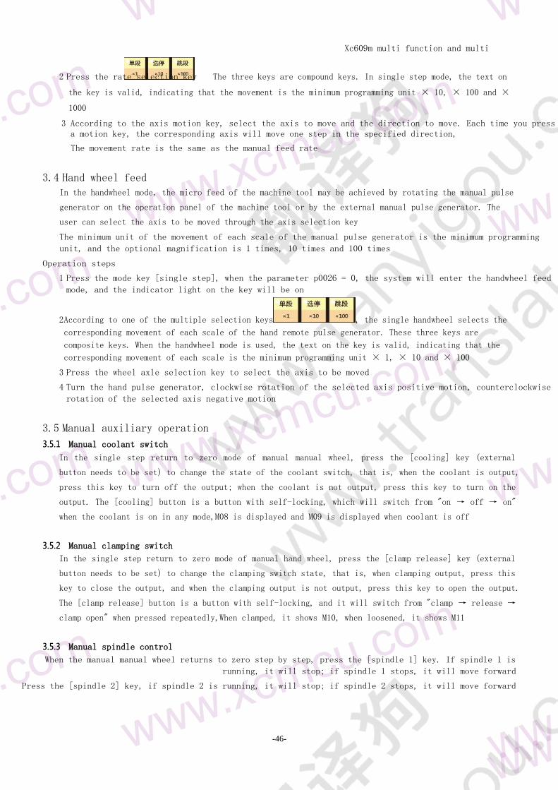
33 Single step feed
In the single step feed mode select the movement key of the axis to be moved Each press can make
the selected axis move step by step in the selected direction The minimum unit of movement is the
minimum programming unit of the system and the input multiple of each step can be 10 times 100
times and 1000 times
Operation steps
1 Press the mode key [single step] the system enters the single step feeding mode and the indicator light
on the key is on
Xc609m multi function and multi
purpose CNC System Manual
-46-
2 Press the rate selection key The three keys are compound keys In single step mode the text on
the key is valid indicating that the movement is the minimum programming unit times 10 times 100 and times
1000
3 According to the axis motion key select the axis to move and the direction to move Each time you press a motion key the corresponding axis will move one step in the specified direction
The movement rate is the same as the manual feed rate
34 Hand wheel feed In the handwheel mode the micro feed of the machine tool may be achieved by rotating the manual pulse
generator on the operation panel of the machine tool or by the external manual pulse generator The
user can select the axis to be moved through the axis selection key
The minimum unit of the movement of each scale of the manual pulse generator is the minimum programming
unit and the optional magnification is 1 times 10 times and 100 times
Operation steps
1 Press the mode key [single step] when the parameter p0026 = 0 the system will enter the handwheel feed
mode and the indicator light on the key will be on
2 According to one of the multiple selection keys the single handwheel selects the
corresponding movement of each scale of the hand remote pulse generator These three keys are
composite keys When the handwheel mode is used the text on the key is valid indicating that the
corresponding movement of each scale is the minimum programming unit times 1 times 10 and times 100
3 Press the wheel axle selection key to select the axis to be moved
4 Turn the hand pulse generator clockwise rotation of the selected axis positive motion counterclockwise
rotation of the selected axis negative motion
35 Manual auxiliary operation
351 Manual coolant switch
In the single step return to zero mode of manual manual wheel press the [cooling] key (external
button needs to be set) to change the state of the coolant switch that is when the coolant is output
press this key to turn off the output when the coolant is not output press this key to turn on the
output The [cooling] button is a button with self-locking which will switch from on rarr off rarr on
when the coolant is on in any modeM08 is displayed and M09 is displayed when coolant is off
352 Manual clamping switch
In the single step return to zero mode of manual hand wheel press the [clamp release] key (external
button needs to be set) to change the clamping switch state that is when clamping output press this
key to close the output and when the clamping output is not output press this key to open the output
The [clamp release] button is a button with self-locking and it will switch from clamp rarr release rarr
clamp open when pressed repeatedlyWhen clamped it shows M10 when loosened it shows M11
353 Manual spindle control
When the manual manual wheel returns to zero step by step press the [spindle 1] key If spindle 1 is
running it will stop if spindle 1 stops it will move forward
Press the [spindle 2] key if spindle 2 is running it will stop if spindle 2 stops it will move forward
Xc609m multi function and multi
purpose CNC System Manual
-47-
Xc609m multi function and multi
purpose CNC System Manual
-48-
Chapter 4 automatic operation The operation of machine tool under program control is called automatic operation There are several
types of automatic operation including program operation MDI operation and drilling function
41 Program running
In automatic mode running a program stored in memory in
advance is called program running Automatic mode can run
main program sub program a and sub program B at the same
time
It can also only run the main program by setting whether the auxiliary program in the
comprehensive parameters is started with the main program (p0010 p0013) The
auxiliary program can be opened with M31 instruction in the main program otherwise
it will not work and the auxiliary program cannot run the M31 instruction
The sub program is not completely equivalent to the main program the main purpose is to do loading and
unloading
For the method of using the auxiliary
program refer to the parameters p0010
~ p0015
P0010 = 0 can only call M31 P1 start program a in
the main program P0010 = 1 press the main start key
the main program will run and program a will also
start P0010 = 2 can be set as [secondary a start]
through the external key
Here are some similarities and differences between the main program and the sub program
Program function main
progra
m
Subroutine
G1 straig
ht
line
The secondary contour can not be
approximated
G2G3G12 suppor
t
I wont support it
Workpiece coordinate system
cutter compensation spindle
Shared any program changes other programs
change at the same time
M31 M32 open close program suppor
t
I wont support it
In principle different programs cant specify the same axis movement at the same time If there is
such a situation it will be executed in sequence which program will execute first and other programs
will wait Therefore the sequence can not be predicted One solution is to use auxiliary relay
communication between programs
Operation steps
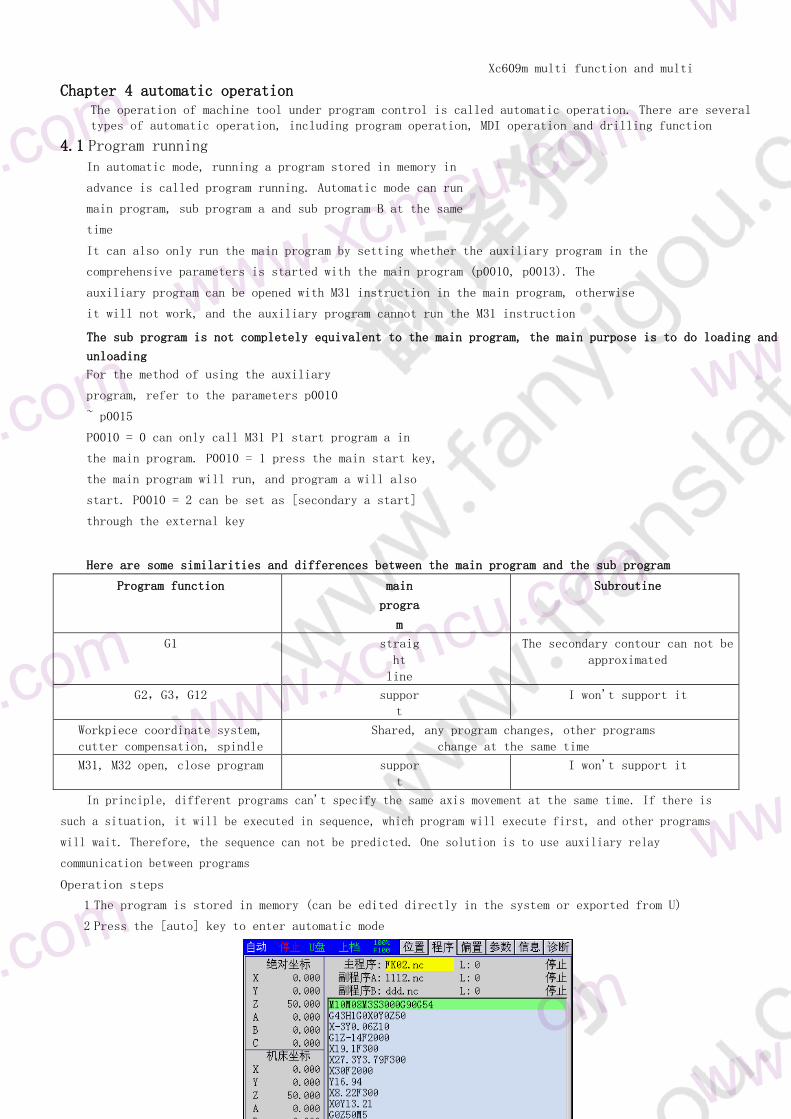
1 The program is stored in memory (can be edited directly in the system or exported from U)
2 Press the [auto] key to enter automatic mode
Xc609m multi function and multi
purpose CNC System Manual
-49-
wwxcmcuc
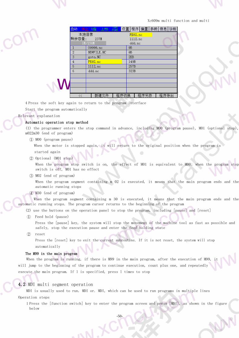
3 Press [function switch] to enter the program screen then press the [local directory] soft key and
then press [uarr] [darr] to retrieve the program to be executed
Xc609m multi function and multi
purpose CNC System Manual
-50-
wwxcmcuc
4 Press the soft key again to return to the program interface
Start the program automatically
Relevant explanation
Automatic operation stop method
(1) the programmer enters the stop command in advance including M00 (program pause) M01 (optional stop)
m022m30 (end of program)
① M00 (program pause)
When the motor is stopped again it will return to the original position when the program is
started again
② Optional (M01 stop)
When the program stop switch is on the effect of M01 is equivalent to M00 when the program stop
switch is off M01 has no effect
③ M02 (end of program)
When the program segment containing m 02 is executed it means that the main program ends and the
automatic running stops
④ M30 (end of program)
When the program segment containing m 30 is executed it means that the main program ends and the
automatic running stops The program cursor returns to the beginning of the program
(2) use the buttons on the operation panel to stop the program including [pause] and [reset]
① Feed hold (pause)
Press the [pause] key the system will stop the movement of the machine tool as fast as possible and
safely stop the execution pause and enter the feed holding state
② reset
Press the [reset] key to exit the current subroutine If it is not reset the system will stop
automatically
The M99 in the main program
When the program is running if there is M99 in the main program after the execution of M99 it
will jump to the beginning of the program to continue execution count plus one and repeatedly
execute the main program If l is specified press l times to stop
42 MDI multi segment operation
MDI is usually used to run MDI or MDI which can be used to run programs in multiple lines
Operation steps
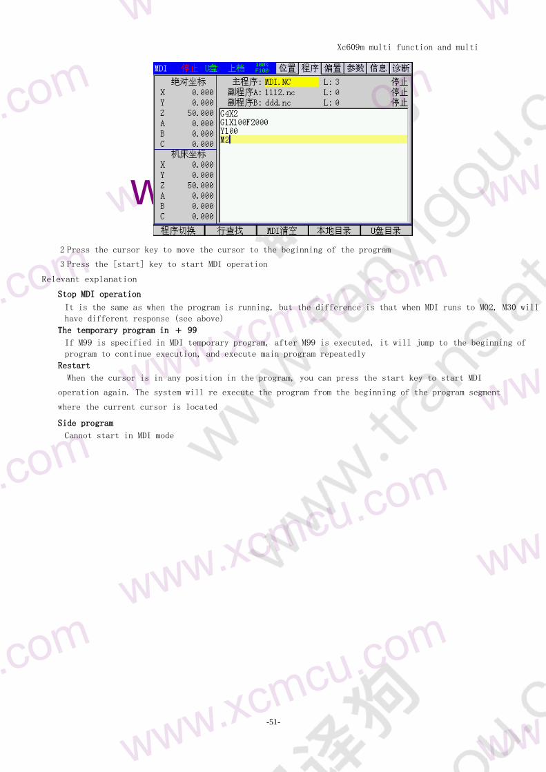
1 Press the [function switch] key to enter the program screen and press [MDI] as shown in the figure
below
Xc609m multi function and multi
purpose CNC System Manual
-51-
wwxcmcuc
2 Press the cursor key to move the cursor to the beginning of the program
3 Press the [start] key to start MDI operation
Relevant explanation
Stop MDI operation
It is the same as when the program is running but the difference is that when MDI runs to M02 M30 will
have different response (see above)
The temporary program in + 99
If M99 is specified in MDI temporary program after M99 is executed it will jump to the beginning of
program to continue execution and execute main program repeatedly
Restart
When the cursor is in any position in the program you can press the start key to start MDI
operation again The system will re execute the program from the beginning of the program segment
where the current cursor is located
Side program
Cannot start in MDI mode
Xc609m multi function and multi
purpose CNC System Manual
-52-
wwxcmcuc
xcm w
Chapter V trial operation Before actual machining in order to test the correctness of the machining program the functions
described in this chapter can be used to debug the machining program
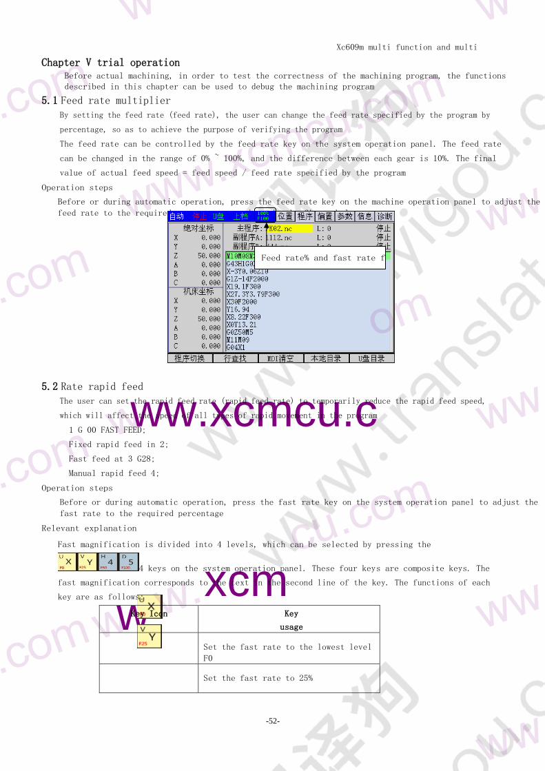
51 Feed rate multiplier
By setting the feed rate (feed rate) the user can change the feed rate specified by the program by
percentage so as to achieve the purpose of verifying the program
The feed rate can be controlled by the feed rate key on the system operation panel The feed rate
can be changed in the range of 0 ~ 100 and the difference between each gear is 10 The final
value of actual feed speed = feed speed feed rate specified by the program
Operation steps
Before or during automatic operation press the feed rate key on the machine operation panel to adjust the
feed rate to the required percentage as shown in the figure below
52 Rate rapid feed
The user can set the rapid feed rate (rapid feed rate) to temporarily reduce the rapid feed speed
which will affect the speed of all types of rapid movement in the program
1 G 00 FAST FEED
Fixed rapid feed in 2
Fast feed at 3 G28
Manual rapid feed 4
Operation steps
Before or during automatic operation press the fast rate key on the system operation panel to adjust the
fast rate to the required percentage
Relevant explanation
Fast magnification is divided into 4 levels which can be selected by pressing the
4 keys on the system operation panel These four keys are composite keys The
fast magnification corresponds to the text in the second line of the key The functions of each
key are as follows
Key Icon Key
usage
Set the fast rate to the lowest level
F0
Set the fast rate to 25
Feed rate and fast rate f
Xc609m multi function and multi
purpose CNC System Manual
-53-
Set the fast rate to 50
Set the fast rate to 100
Note the fast rate is F0 which can be specified in the comprehensive parameter (P 0024)
53 Single program segment
When the single program segment switch is turned on the system will stop after one program segment is
executed After restart the system will stop again after executing the next program segment Users
can execute the whole program one by one which is often used to check whether the execution results
of multiple program segments meet the expectations
Xc609m multi function and multi
purpose CNC System Manual
-54-
notes
Users can not accurately predict when the program segment will be read into the buffer
register In order to ensure the effect of the skip switch it is necessary to run the
program automatically
There is a certain risk to turn on the trip switch before the line and in automatic
operation
The switch of one-way sequence section is controlled by the [single section] key on the machine tool
This key is like a button with self-locking When the indicator light on the key is on it means that
the one-way sequence section switch is on and when the light is off it means that the one-way
sequence section switch is closed
Operation steps
Before the automatic mode press the [single segment] key to make the indicator light on the key on After
the program starts to execute the first program segment will stop
Press the key of [1] to stop the execution of the program
54 Skip optional segments
When the skip optional segment switch is on the system will ignore the program segment containing
The skip section switch is controlled by the [skip section] key on the panel of the machine tool Like
a button with self-locking the [skip section] key will switch in the on rarr off rarr on mode when it
is pressed several times When the indicator light on the key is on it means that the section
skipping switch is on when the indicator light on the key is off it means that the section skipping
switch is closed
Operation steps
Before or during the automatic operation press the [skip section] key to make the indicator light on the
key on At this time the system will not execute the program section containing in this case
Operation explanation
When the instructions contained in a program segment are read from memory to the buffer register the
system decides whether to skip the program segment according to the status of the skip switch and
whether it contains in the program segment However the program segment that has been read into
the buffer register is not affected by the skip switch
Xc609m multi function and multi
purpose CNC System Manual
-55-
Xc609m multi function and multi
purpose CNC System Manual
-56-
Chapter 6 safe operation
61 Power on
Before the system is
powered on it should
be confirmed that 1
The state of the
machine tool is normal
2 The power supply voltage meets the requirements
3 The wiring is correct and firm
After the system is powered on the boot screen will be displayed (the user can modify it by himself)
At this time the system self-test initialization After the completion of self-test and initialization
the comprehensive position page is displayed
62 Shut down
Before shutdown confirm that
The feed axis of 1cnc is in stop state
2 Auxiliary functions are off
3 First cut off the CNC power supply and then cut off the power supply of the machine tool
63 Super program protection
In order to avoid damage to the machine tool caused by over travel of each feed shaft over travel
protection measures must be taken
631 Hardware over range protection
Generally limit switches (travel switches) are installed in the positive and negative directions of
each axis The tool can only move within the range limited by the positive and negative limit switches
of each axis When the tool tries to cross the limit switch the limit signal is valid and the system
immediately stops the tool movement and displays the over travel alarm information
In case of overtravel the reverse moving tool (such as positive overtravel negative moving
negative overtravel forward moving) will break away from the limit switch The alarm can be reset and
released after the limit is broken
632 Over range protection software
Software overtravel protection is similar to hardware overtravel protection The positive and
negative limit coordinates of software overtravel correspond to the limit switch of hardware
overtravel The positive and negative limit coordinates of each axis are respectively set in the
parameters and their limited range is called soft limit
When the machine tool coordinate will exceed the soft limit the system will stop the tool
movement immediately and display the over travel alarm Manually move the tool in reverse
direction to make the machine coordinate of each axis enter the limited range which can be reset
to release the alarm
64 Emergency operation
In the process of processing due to user programming improper operation or product failure some
unexpected results may occur At this time the system must stop working immediately This section
describes the processing that the system can carry out in emergency For the treatment of the machine
tool in emergency please refer to the relevant instructions of the machine tool manufacturer
641 reset
Xc609m multi function and multi
purpose CNC System Manual
-57-
When the machine tool outputs abnormally or the coordinate axis moves
abnormally press the [reset] key to reset the system immediately
2 Cooling spindle rotation stop output
3 Automatic operation ends
642 Emergency stop
During the operation of the machine tool in case of danger or emergency the emergency stop button
should be pressed The system will immediately control the machine tool to stop moving stop the
output cooling stop the spindle rotation and display the emergency stop alarm
After releasing the emergency stop button the emergency stop alarm will be released and the system
will enter the reset state In order to ensure the correctness of the coordinate position the
mechanical zero returning operation should be performed again after the emergency stop alarm is
released (the machine tool without mechanical zero point shall not return to zero)
643 Cut off the power supply
During the operation of the machine tool in case of danger or emergency the
power supply of the machine tool can be cut off immediately to prevent
accidents After the power supply is cut off the coordinate displayed by the
system may deviate greatly from the actual position so it is necessary to
adjust the tool again
Xc609m multi function and multi
purpose CNC System Manual
-58-
wwxcmcuc
notes
1 Although MDI mode can edit ordinary programs it is not recommended to do so MDI mode
is generally only used for editing and performing some simple operations
2 Super large program (more than 200KB) can not be edited It can only be copied to
personal computer through U disk edited and modified by Notepad and then downloaded to
the CNC system through U disk
3 There is no limit to the number of programs in this CNC system
4 The standard configuration memory capacity of this CNC system is 128M
Chapter 7 program editing
71 summary Users can edit programs directly in the system
step
The general procedures
are as follows 1
2 Switch to the program screen
3 Switch to edit mode teaching mode or MDI (input) mode
4 Use the address keys number keys backspace and function keys of the keyboard to insert and delete
programs
explain
Program area
Program area refers to the display and editing window of the program in the system as shown in the figure
below
The steps to enter the program area
of the program screen are as
follows 1 Press the [program] key
to enter the program screen
2 At this time press [Edit] and [teaching area] to switch to edit
3 Press [program switch] to switch the display of main and auxiliary programs
Working mode and program protection switch
The system must be switched to edit mode or MDI mode to edit program When editing MDI temporary
program it is not necessary to turn on the program protection switch while editing ordinary
program the program protection switch must be turned on
The program switch can protect the program from accidental modification The user can turn it off in the
system information screen of chapter 273
72 Teaching program
The teaching program can easily write some programs which do not require very accurate and can input the
Xc609m multi function and multi
purpose CNC System Manual
-59-
absolute coordinate value automatically
[edit edit and teach] is switched to teaching programming and the teaching light flashes At this time it
is turned on manually by default or you can press [single step] to switch to the handwheel
The axis and edit mixed key is axis selection when the manual lamp is turned on If it is a single handwheel mode it is also an axis selection If it is a hand-held handwheel it is an editing key Teaching programming must be absolute programming When you press the character keys x y Z a B C I J K if the corresponding axis is valid the current absolute coordinates will be automatically added If [ESC] is pressed all the valid axis positions will be input at one time
Xc609m multi function and multi
purpose CNC System Manual
-60-
wwwx
mcucom
In teaching programming and arc programming only the 3-point circle interpolation command G12 can be used Because the relative coordinates cannot be input there is no difference between the key of invalid axis and the editing mode so it can be input normally
73 New program
Figure a and figure B
step
1 Press the [program] key to enter the program screen
2 Press the [local directory] soft function key to enter the local directory screen
3 Press the [new program] soft function key to open the dialog box of new processing program and input
the file name XY of processing program as shown in Figure a
4 Press the [Enter] key to confirm As shown in Figure B xync file name appears in the left
directory If it is a subprogram please name it oxxxx which means pure number
5 Press the left most soft function key to return to the main program screen
74 One line program
step
1 In the program editing state press the cursor keys [larr] and [rarr] to move the cursor to the front of the
program line to be inserted
2 Press the [Enter] key to change the line The original program will move down and edit a new line up
3 Use the keyboard address keys number keys backspace and other function keys to edit the program
explain
1 [backspace] key is to delete the previous character
2 [delete] key is to delete the next character
3 [insert] key is used to switch between insert and edit mode
Xc609m multi function and multi
purpose CNC System Manual
-61-
Xc609m multi function and multi
purpose CNC System Manual
-62-
Note
In the same machining program users can use G90 or G91 to switch the instruction mode
according to their needs G900g91 is the same group of mode g codes After one instruction is
given the mode remains valid until another G code of the same group is instructed
Chapter 1
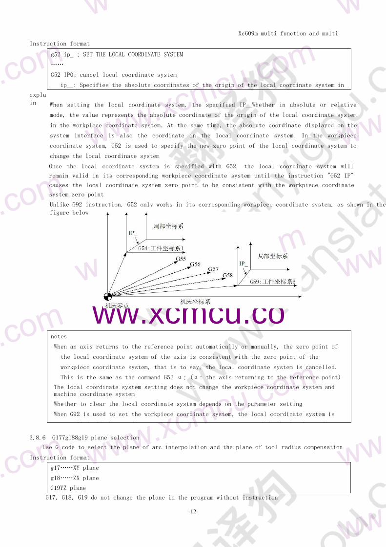
Introduction to
programming
Chapter 3 programming instructions
There are two ways to command axis movement absolute value command and increment value command
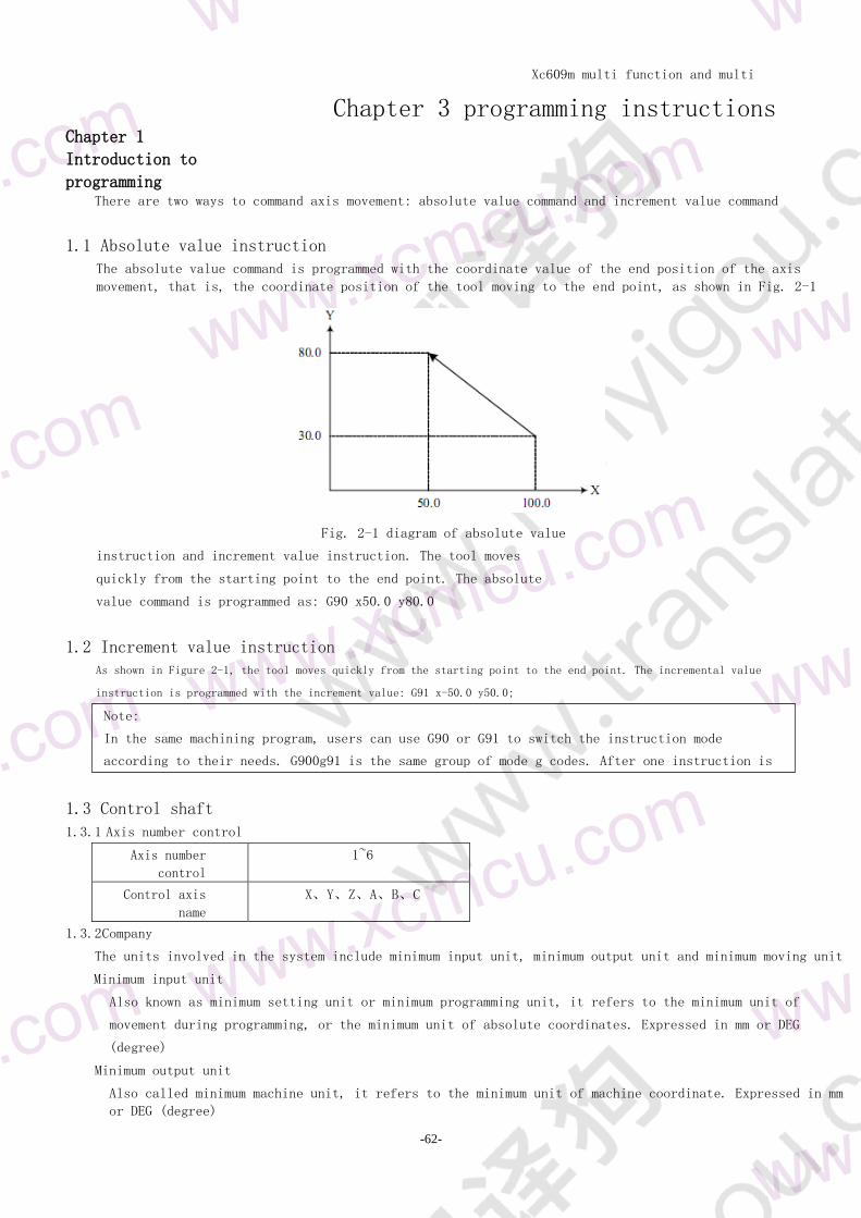
11 Absolute value instruction
The absolute value command is programmed with the coordinate value of the end position of the axis
movement that is the coordinate position of the tool moving to the end point as shown in Fig 2-1
Fig 2-1 diagram of absolute value
instruction and increment value instruction The tool moves
quickly from the starting point to the end point The absolute
value command is programmed as G90 x500 y800
12 Increment value instruction As shown in Figure 2-1 the tool moves quickly from the starting point to the end point The incremental value
instruction is programmed with the increment value G91 x-500 y500
13 Control shaft
131 Axis number control
Axis number
control
1~6
Control axis
name
XYZABC
132 Company
The units involved in the system include minimum input unit minimum output unit and minimum moving unit
Minimum input unit
Also known as minimum setting unit or minimum programming unit it refers to the minimum unit of
movement during programming or the minimum unit of absolute coordinates Expressed in mm or DEG
(degree)
Minimum output unit
Also called minimum machine unit it refers to the minimum unit of machine coordinate Expressed in mm
or DEG (degree)
Xc609m multi function and multi
purpose CNC System Manual
-63-
Minimum unit of movement
Or (1 degree) to the system
Quick guide
Minimum unit of linear axis
The minimum input unit for a linear axis is metric input
Minimum axis of rotation
Xc609m multi function and multi
purpose CNC System Manual
-64-
XYZUVWABCIJKQRFEH
The unit of rotation axis is expressed in deg
The minimum unit is suspended
The minimum unit of pause is 0001 seconds which has
nothing to do with the minimum unit of linear axis or
rotating axis Please refer to the instruction manual of
the machine tool manufacturer for detailed setting unit
14 Decimal point programming
Values can be entered with a decimal point Decimal points can be used for instruction values that
represent units of distance time and speed Such address values are shown below
Depending on the address and instruction the decimal point
can be in millimeters degrees or seconds Note that x1
x10 is considered to be 1000 unlike other controllers
Xc609m multi function and multi
purpose CNC System Manual
-65-
Xc609m multi function and multi
purpose CNC System Manual
-66-
wxc
Main program subprogram
Main subroutine subroutine
One nesting and two nesting
Chapter II composition of procedure
21 program The program is composed of multiple program segments which are separated by block end codes
211 Main program and subprogram
2111 main program
The program is divided into main program and subprogram Generally CNC machine tool moves according
to the instruction of main program If there is instruction calling subroutine during the execution
of main program it will be executed by subroutine When the instruction returning to main program is
encountered in subprogram it will return to main program to continue execution
Program segment 1 Program segment 1
Program segment 2 Program segment 2
helliphellip helliphellip
helliphellip helliphellip
helliphellip helliphellip
Call Subroutine
instruction
Return to the main
program
instruction
helliphellip
helliphellip
2112 subroutine
When there are some fixed sequence and repeated program segments in the machining program they
can be edited as subprograms The main program can call subprograms when necessary so that the
programming can simplify the main program Subprograms can be called out when the main program is
running and the transferred subprograms can also call other subprograms
O0001 O1000 O2000
helliphellip helliphellip helliphellip
helliphellip helliphellip helliphellip
helliphellip helliphellip helliphellip
M98 P1000 M98 P2000 helliphellip
helliphellip helliphellip helliphellip
helliphellip helliphellip M99
M30 M99
The subroutine
can be embedded in 4
layers Preparation of subroutines
Xc609m multi function and multi
purpose CNC System Manual
-67-
main program
Subroutine sequence number
Subroutine content
End of subroutine
OXXXX
helliphellip
helliphellip
helliphellip
helliphellip
helliphellip
helliphellip
M99
Write a subroutine in the following format
Xc609m multi function and multi
purpose CNC System Manual
-68-
xc
Example
xm99
Note
In order to be used interchangeably with other devices the subroutine at the beginning of
the program segment can use Noooo instead of oooooo The sequence number immediately
following n is stored in the memory as the subroutine number
M98 PXXXX LNN
NN the number of
repeated calls XXX the
number of subroutines to
be called
example
X1000 M98 P1200
Note
When the subroutine number specified by address P cannot be retrieved an alarm is generated
At the beginning of the subroutine write the subroutine serial
number after the address o and at the end of the subroutine is
the M99 instruction
The execution of subprogram
The subroutine is called out and executed by the main program or subroutine calling instruction
If the number of repetitions is omitted the number of repetitions is considered to be one
Indicates that the subroutine with program number 1002 is called 5 times continuously
The M98 instruction can also be programmed in a block with the move instruction
At this time after the x-axis movement is
completed the subroutine No 1200 is called
N0010 helliphellip O1010 helliphellip
N0020 helliphellip N1020 helliphellip
N0030 M98 P1010L2 N1030 helliphellip
N0040 helliphellip N1040 helliphellip
N0050 M98 P1010 N1050 helliphellip
N0060 helliphellip N1060 M99
Calling a subroutine in a subroutine is the same as calling a subroutine in a main program
2 in the main program if M99 is executed it will return to the beginning of the main program and
continue to execute repeatedly For example if there is a program segment M99 in the main
program if the skip optional program segment switch is off then execute M99 return to the
beginning of the main program and repeat from the beginningThe next program segment is skipped
example
M98 P1002L5
Xc609m multi function and multi
purpose CNC System Manual
-69-
w
cu
example
N100 X1000
N101 Z1000
N102 X200
NXXXXX
Program number Address
Xxxxx sequence number (leading zeros can be omitted)
OXXXX
O program number address symbol
XXX program number (1 ~ 9999 leading zeros can be omitted)
212 Program number
N programs can be stored in the memory of the system which can be distinguished by the program
number composed of address O and the following four digits (the program name imported from U
disk can be Chinese) The program starts with the program number and ends with M30 or M02
format
213 Program number and program segment
A program is composed of multiple program segments which are separated by a segment Terminator ()
At the beginning of the program segment the address N and the
following five digits can be used to form the sequence number
and the leading zero can be omitted
explain
The sequence number can be arbitrary and its interval can also be unequal The sequence number
can be inserted in all program segments or only in important program segments It is convenient
to carry the sequence number in important parts of the program For example when changing tools
or when the table index is moved to a new machining surface etc
214 Skip optional segments
In automatic operation a block with a slash (()) at the beginning is skipped by the system when the
trip switch is on If the trip switch is off the block will not be skipped
If the switch is opened in the program section n101 it is skipped
215 Word and address
jump Turn the switch off
N0010 helliphellip
N0020 helliphellip
N0030 helliphellip
N0040 helliphellip
N0050 M99
N0060 helliphellip
N0070 helliphellip
jump Turn the switch on
Xc609m multi function and multi
purpose CNC System Manual
-70-
X1000
x
Address
1000
value
A word is a component of a program segment It consists of an
address and a number after it The value can be negative
Xc609m multi function and multi
purpose CNC System Manual expla
in
-71-
Address is a letter in the English letters (a ~ z) which specifies the meaning of the
subsequent values According to different preparation functions sometimes the same address has
different meanings In this system the addresses that can be used and their meanings are shown
in the table below
func
tion
addr
ess
sign
ific
ance
Program number O Program number
Sequence number N Sequence number
Preparation
function
G Specify action state (line arc etc)
Size words
X Y Z A B C U V W H Axis movement command
R arc radius
I J K The center of the arc is G12
Feed rate F Specified feed rate
Spindle function SSS Spindle speed designation s spindle 1 SS spindle
2
Tool function T Designation of tool number
Auxiliary function M Auxiliary functions of machine tool
Offset number HHX
HYHZHAHBHC
The offset of each tool is consistent with Hz
suspend PX Designation of pause time
Assignment of
subroutine
sequence number
P Specifies the sequence number of the subroutine
Number of
repetitions
L Number of repetitions of subroutines
parameter PQR Fixed cycle parameters
216 Base address and instruction value range
The base address and instruction value ranges are shown in the table below
func
tion
addr
ess
Mm input
Program number O 1〜9999
Sequence number N unlimited
Preparation
function
G 0〜99
Size words X Y Z A B C U V W I J K Q R plusmn999999999
Feed per minute F 0001〜150000
Spindle function S 0〜9999
Auxiliary function M 0〜99
suspend X P 0〜999999999S
The subroutine
number is
specified
Number of
P
1〜9999
Xc609m multi function and multi
purpose CNC System Manual expla
in
-72-
M30 program end
M99 subroutine
end
repetitions
Number of
repetitions
L 1〜99999
Offset number HHXHYHZHAHBHC 0〜99
For example the system can command another axis movement of about 100 m while the actual
machine tool X-axis travel may be only 2 M when writing the program you should refer to this
manual and the machine manual at the same time
22 End of procedure
Program ends with M30
or M99
Xc609m multi function and multi
purpose CNC System Manual expla
in
-73-
In the execution of the program if the above program code is encountered the system ends the program
execution and enters the reset state
At the end of M 30 whether the program cursor returns to the beginning of the program is
controlled by the bit parameter M30 At the end of the subroutine the system returns to the
program calling the subroutine to continue execution
Xc609m multi function and multi
purpose CNC System Manual expla
in
-74-
Xc609m multi function and multi
purpose CNC System Manual
-75-
Type 1 modeless G code
Type 2 mode G code is
only valid in the
instructed segment
Valid until other G code instructions in the same group example
G00 and G01 are the same group of modal g
codes The processing procedure is as follows
g00x__ (G00 valid)
Y__ (G00 valid)
g01z__(X) EFFECTIVE__
(G01 valid)
Chapter 3 preparation function (G code) The preparation function is represented by G code including G address
and its subsequent value
31 G code list
G code leve
l
func
tion
G00
01
Fast positioning speed according to the speed parameter G0 speed in the
comprehensive parameters can be selected linear and non-linear
G01 Linear interpolation run according to the given F
G02 Clockwise circular arc interpolation the speed is given F if there is a
non planar axis according to the spiral interpolation operation
G03 Anti clockwise arc interpolation the others are the same as above
G12 Circular interpolation through intermediate point
G04 00 Press the parameter P 5 ms and wait for the parameter
G17
02
Circle interpolation plane selection XY
G18 Circle interpolation plane selection ZX
G19 Circle interpolation plane selection YZ
G28
00
Return to the parameter point (return to mechanical zero) involving
parameters such as speed return to zero direction and mode
G31 If G31 input port effectively stops the current movement to the next
instruction
G50 When the side position moves the input port stops invalid similar to
G31 but the input port can be specified arbitrarily
G51 The input port stops effectively when the side position moves similar to
G31 but the input port can be specified arbitrarily
G22
0 Loop instruction
G23 Loop instruction
G43
05
The tool length compensation in the positive direction is independent of
the plane and is always on the Z axis and the other axes are invalid
G44 The tool length compensation in negative direction is independent of the
plane and is always on the Z axis and other axes are invalid
G49 Tool length compensation is cancelled always in Z axis other axes are
invalid
G52
00 Local coordinate function
G53 Coordinate positioning of machine tool
G54
Workpiece system 1
G55 Workpiece coordinate system 2
Xc609m multi function and multi
purpose CNC System Manual
-76-
G56
06
Workpiece coordinate system 3
G57 Workpiece coordinate system 4
G58 Workpiece coordinate system 5
G59 Workpiece coordinate system 6
G73
07 High speed deep hole machining cycle
G74 Back tapping cycle tapping by encoder
Xc609m multi function and multi
purpose CNC System Manual
-77-
Note
The G code with is the default G code of the system When the power is on the mode G
code will be in the default state
The G code of group 200 is modeless G code which is valid only in the current program
segment
If G codes not listed or enabled in G code list are used an alarm will appear
Several different groups of G codes can be instructed in the same block If more than one
group of G codes are instructed in the same block the last G code is valid
G00 IP__
IP X y Z a B C u V W etc indicating the combination of any axis For absolute
value command it is the end coordinate value of tool movement and for increment
value instruction it is tool movement amount
Semicolon () indicates the end of a program segment
G80 Fixed cycle cancellation
G81 Drilling cycle (spot drilling cycle)
G82 Drilling cycle (boring step empty cycle)
G83 Deep hole drilling cycle
G84 Tapping cycle tapping by encoder
G85 Boring cycle
G86 Drilling cycle
G88 User defined drilling instruction specific action re drilling function
in G88 editing
G89 Boring cycle
G90
08 Absolute value programming
G91 Incremental value programming
G92
00 Set the workpiece coordinates When there is no mechanical return to
zero all workpiece coordinates will be offset
G93 Set the machine coordinate if there is soft limit please use it
carefully
G98
9 Fixed loop returns to the initial plane
G99 Fixed loop returns to R point
32 G00 fast positioning Go to the current position according to the speed of g000
Instruction format
Instructions
Non linear interpolation positioning
Linear and non-linear can be selected in the comprehensive parameters
When G00 is executed each axis is positioned at an independent fast moving speed If x and Z
axes are specified at the same time the tool path is not a straight line That is to say in
the process of G00 the moving axis at the same time does not do linear interpolation but
selects the optimal path It is usually used in stepper motor system
Linear interpolation positioning
Linear and non-linear can be selected in the comprehensive parameters
When G00 is executed the tool path is the same as that of G01 and the tool is positioned in the
shortest time at a speed not greater than that of each axis
The two methods are defined in the parameter (P0028)
and the subroutine can only be non-linear
Xc609m multi function and multi
purpose CNC System Manual
-78-
wwxcmcuc
wxcmcu
G01 IP__ F__
IP for absolute command it is the end coordinate value of tool
movement for incremental command it is tool movement amount F
tool feed rate
33 G01 linear interpolation G01 is a linear interpolation instruction It takes the current
point as the starting point uses IP to specify the end point and F
to specify the speed In the subroutine it moves approximately in
a straight line
Instruction format
Instructions
The feed rate specified by F is always valid until a new value is
specified so it is not necessary to specify one by one for each
program segment The speed specified by F is the composite speed of
the tool moving along a straight line
give an example
34 Circular interpolation G022g03 are circular interpolation instructions They control the
cutting motion of the tool along the arc on the specified plane The
subroutine cannot run this instruction
G91 G01 X2000 Y1000 F2000
The tool moves from the starting point (00) to the end point (20001000) at a speed of 200
mmmin
notes
1 The fast moving speed of each axis of G00 is set by parameters and the feed speed
specified by F is invalid
5 F 50 F 0
2 When G 000 the next instruction can not be omitted
3 Attention should be paid to the safe position of the cutter when the command G00 is given
Xc609m multi function and multi
purpose CNC System Manual
-79-
Circular arc of XY plane
Instruction format
Xc609m multi function and multi
purpose CNC System Manual
-80-
m
wwwx
proj
ect
Specified
content
comm
and
desc
ribe
1
Plane
assignment
G17 XY plane arc assignment
G18 Circular arc ZX plane
G19 YZ plane arc assignment
2
Interpolatio
n direction
G02 Clockwise arc interpolation (CW)
G03 Anti clockwise arc interpolation (CW)
3
The position or
distance of an
end point
Two axes in X y Z The position of the end point in the absolute
coordinate system
W or u
Two axes in XYZ
under G91
The distance from the starting point
coordinate to the ending point coordinate
4
Center position
or radius
Two axes in I J K The distance from the starting point
coordinate to the center coordinate (I J K in
absolute mode
It is also calculated in increments)
R arc radius
5 Feed rate F Tangent speed of arc feed
Instructions
The direction of circular interpolation
The so-called clockwise (G02) and counter clockwise (G03) mean that in the right-hand rectangular
coordinate system for X_y_Plane (z_x_Plane y_z_From z) plane_Axis (Y_Axis X_As shown in the
figure below
The movement of the arc
With address x_y_Or Z_Specify the end point of the arc Under the G90 command it represents
the absolute value and the G91 instruction indicates the increment value The increment value
(image) circular arc of ZX plane
Arc of YZ plane
Xc609m multi function and multi
purpose CNC System Manual
-81-
is the distance value from the start point of the arc to the end point
Center of arc
The center of the arc is specified by the addresses I J K which correspond to x
respectively_y_z_The values after I J and K are vector components from the starting point
of the arc to the center of the circle and are the increment values with signs
Xc609m multi function and multi
purpose CNC System Manual
-82-
wwwxcmcucom
wwxcmcuc
notes
1 When I J and K are 0 they can be omitted
2 If the movement of all arcs (x y z) is ignored the end point is the same as the
starting point If I J K are used to specify the center of the circle then a whole
circle is specified
3 At the same time the position of the starting point is not generated
4 The error of the actual moving speed of the tool relative to the specified speed is
within plusmn 2 and the specified speed is the speed of the tool moving along the arc
after radius compensation
When I J K and R are specified simultaneously R is valid I J K are invalid
Absolute way
G92 X2000 Y400 Z0
G90 G03 X1400 Y1000 I-600 F3000
G02 X1200 Y600 I-500
or
G92 X2000 Y400 Z0
Arc radius
① When the arc is less than 180 degrees execute G code G91 G02 X60 Y50 R50 F300
② When the arc is greater than 180 execute G code G91 G02 X60 Y50 R-50 F300
The feed rate
The feed rate of circular interpolation is specified by F which is the tool speed along the tangent
direction of arc
give an example
The trajectories on the graph are programmed with absolute value mode and incremental value mode respectively
Xc609m multi function and multi
purpose CNC System Manual
wwxcmcuc
wwxcmcuc
-51-
m
wwwx
34 Spiral interpolation
If the axis out of the specified plane is commanded while circular interpolation is specified the tool
spiral motion
Instruction format
explain
The f command specifies the feed rate along the arc projection circle as shown in the figure below
Length of linear axis F Arc length of arc
projection
G90 G03 X1400 Y1000 R600 F3000
G02 X1200 Y600 R500
Incremental mode
G91 G03 X-600 Y600 I-600 F3000
G02 X-200 Y-400 I-500
or
G91 G03 X-600 Y600 R600 F3000
G02 X-200 Y-400 R500
Circular arc of XY plane
Circular arc of ZX plane
Arc of YZ plane
Xc609m multi function and multi
purpose CNC System Manual
-2-
Circular arc
in XY plane
G12 I j x y ZX
plane arc in
plane G12 I k
x z YZ plane
G12 J K Y Z
g04 x__
OR
G04 P__
x Delay waiting time setting
(decimal can be used) P delay
waiting time setting (decimal can not
be used)
notes
The unit of 1 xxp instruction is independent of the minimum unit of the linear axis or
rotation axis
2 If P and X instructions are omitted they can be regarded as accurate stop
3 Execution of the G04 instruction will automatically disable read ahead and buffering
35 G12-3 point circular interpolation They control the cutting motion of the tool along the arc on the specified
plane The subroutine cannot run this instruction
Instruction format
i J K are the middle point of the arc absolute at g 90 and relative at g 91
x Y Z are the end of the arc absolute at g 90 and relative at g 91
This instruction is mainly used for teaching programming
It is better to take the middle point of the arc to reduce the calculation error
36 G04 delay waiting The execution of the next program segment can be delayed by using the delay wait instruction
Instruction format
Instructions
By using the pause instruction the execution of the next program segment can be delayed for a specified
period of time
Instruction word Scope of
instruct
ion
Command unit
X 0001〜99999999 se
co
nd
P 1〜99999999 0001 seconds
37 Reference point function The so-called reference point is a specific position on the machine When there is a mechanical zero
point the mechanical zero point is the reference point of the machine tool when there is no
mechanical zero point the set floating zero point can also be regarded as the reference point of the
machine tool It can be returned to the reference point under the manual mechanical zero return mode
or the tool can be automatically returned to the reference point by using G28 command
notes
When the feed rate f is specified the speed of the linear axis should not exceed any
limit value
Xc609m multi function and multi
purpose CNC System Manual
-3-
371 G28 - Auto return to reference point
G29 Return to the reference point automatically through the reference point as shown in the figure
below
Xc609m multi function and multi
purpose CNC System Manual
-4-
wwxcmcu
wxcmcu
G28 IP__
G28 Auto return reference point instruction
ip__ COORDINATES OF THE INTERMEDIATE POINT PASSED BY WHEN AUTOMATICALLY RETURNING TO THE
REFERENCE POINT SPECIFIED BY ABSOLUTE OR INCREMENTAL VALUE
example
N1 G28 x400 middle point (400)
060 N 20
notes
1 After power on if the manual return to the reference point is not carried out once
the movement from the intermediate point to the reference point is the same as that
when returning to the reference point manually when G28 is commanded
2 When changing the workpiece coordinate system the intermediate point will also move to
the new coordinate system
Command format
Instructions
Go back to the reference point of G 1
When the machine tool is locked G28 cannot locate from the middle point to the reference point and the
zero return lamp will not be on
3 G28 is usually used in automatic tool change so the compensation of tool radius and length should be
cancelled in advance
In 4 G28 there are several axes in the order of Z gt XY gt ABC
38 Coordinate system function When the machine tool is working the tool moves to the specified position according to the
coordinates specified by the machining program and the coordinate value is specified by the axis
components of the coordinate axis As shown in the figure below the tool position specified by x400
y500 z300 is used
This system uses one of machine coordinate system workpiece coordinate system and local coordinate system
to specify coordinate position
The zero point of machine tool is a fixed reference point set by the machine tool manufacturer
Xc609m multi function and multi
purpose CNC System Manual
-5-
Once the original point of the machine tool is re established the original point of the machine
tool will be fixed at the original point of the machine tool
The workpiece coordinate system is based on the sub coordinate system of the machine tool coordinate
system
Xc609m multi function and multi
purpose CNC System Manual
-6-
wwxcmcuc
G53 IP__
ip__ THE ABSOLUTE COORDINATE OF THE TARGET POINT IN THE MACHINE COORDINATE SYSTEM
notes
When the g53 command is specified the compensation such as tool radius and length will be
cleared automatically
The 2 g53 instruction suppresses G code read ahead
G92 IP__
ip__ Specifies the coordinates of the current point in the set workpiece coordinate
system
3 The local coordinate system is based on the sub coordinate system of the
workpiece coordinate system and its position in the workpiece coordinate system
can be set and changed The relationship of each coordinate system is shown in the
following figure
Usually after the system is started the user needs to reset the machine coordinate system
After manually returning to zero or G28 command to return to the reference point the system can
establish the machine coordinate system according to the machine zero point This coordinate
system will be saved in the system until the user reset
381 G53 machine tool coordinate system positioning
According to the specified machine coordinate move the tool to the target position quickly
Instruction format
Instructions
Since the general positioning command (G00) can only specify the target point in the workpiece
coordinate system if the user wants to move the tool to a special position of the machine
tool (such as tool change position) it is more convenient to use g53 command
2 g53 is a modeless G code only valid in the current program segment
The 3 g53 instruction must be absolute If it is an increment instruction an alarm is generated
382 G92 g54 ~ G59 - workpiece coordinate system setting
The coordinate system used in machining parts is called workpiece coordinate system The workpiece
coordinate system needs to be set in advance before machining and the set workpiece coordinate
system can be changed by moving the origin
There are three ways to set
the workpiece coordinate
system 1 G92 to set the
workpiece coordinate system
2 Automatic setting of workpiece coordinate system
3 G54-G59 workpiece coordinate selection
3821 G92 - set workpiece coordinate system
Instruction format
Xc609m multi function and multi
purpose CNC System Manual
-7-
The workpiece coordinate system is established by specifying the coordinate value (IP__)It
becomes the absolute coordinate value of the point on the current tool (such as the tool tip) in
the set workpiece coordinate system
Under the condition of tool length compensation when G92 is used to set the coordinate system the
coordinate value (IP) is specified__)It is the position before tool compensation
2 For tool radius compensation the compensation disappears temporarily when G92 command is used
Xc609m multi function and multi
purpose CNC System Manual
wwxcmcuc -55-
xcmc
G54 workpiece
coordinate
system 1 G55
workpiece
coordinate
system 2 g56
workpiece
coordinate
system 3 G57
workpiece
coordinate
system 4 g58
workpiece
coordinate
system 5
G59 workpiece coordinate system 6
Generally please set the workpiece coordinate system before specifying tool compensation
give an example
After the coordinate system is established the tool length compensation must be added when the
reference point moves to the designated position in absolute mode The compensation value is the
difference between the reference point and the tool tip
3822 Automatic setting of workpiece coordinate system
If the automatic setting function of coordinate system is selected the system will automatically set
the workpiece coordinate system after returning to the reference point manually or automatically If
α β and γ are the values of setting parameters respectively after returning to the reference
point the absolute coordinate values of tool rest reference point or tool tip position are x = α y
= βThis method is equivalent to the setting of the reference point of the workpiece
3823 Select workpiece coordinate system (G54-G59)
The system provides six workpiece coordinate systems G54-G59 The user can set the workpiece
zero offset data of each coordinate system through the system MDI panel and then select any
workpiece coordinate system When the machine is started and the reference point is returned
g54 coordinate system is selected by default
Instructions
The six workpiece coordinate systems are set according to the distance from the zero point of the machine
tool to the zero point of the respective coordinate system (workpiece zero offset) as shown in the
figure below
G92 Xα Yβ Zγ
Xc609m multi function and multi
purpose CNC System Manual
wwxcmcuc -55-
Xc609m multi function and multi
purpose CNC System Manual
-10-
wxcmcu
wxcmcu
notes
When the workpiece coordinate system is selected G92 is not required to set the
coordinate system If G92 is used the workpiece coordinate system 1 ~ 6 will be moved
Therefore do not mix G92 with g54 ~ G59 unless the workpiece coordinate system 1 ~ 6
is to be moved
Whether the relative position changes with the setting of workpiece coordinate system
depends on the corresponding setting in the parameter
Processing program
N10 G55 G00 X1000 Z200
N20 G56 X805 Z255
G92 IP_
ip__ Specifies the coordinates of the current point in the set workpiece coordinate
system
After the zero point is offset the zero point is returned as shown in the figure below
If the working coordinate system is selected it is generally set to zero in the parameter If
the setting value is not zero all workpiece coordinate systems will offset the set value of
the parameter after returning to the parameter reference point
give an example
383 Moving workpiece coordinate system with G92
Instruction format
Instruction interpretation
When G92 instruction is executed in the selected workpiece coordinate system (G54-G59) all the
original workpiece coordinate systems can be offset synchronously to generate a new coordinate
system All workpiece coordinate systems have the same offset
384 Set machine coordinates (G93)
Set the current machine tool coordinate Please use it carefully when there is soft limit The
workpiece coordinate system will be offset
G93 IP_
Example g93z0 set the current machine coordinate of Z axis to zero
Xc609m multi function and multi
purpose CNC System Manual
-11-
385 G52 local coordinate system
When programming in the workpiece coordinate system in order to simplify we can set another sub
coordinate system in the workpiece coordinate system This sub coordinate system is called local
coordinate system
Xc609m multi function and multi
purpose CNC System Manual
-12-
wwxcmcuco
g17helliphellipXY plane
g18helliphellipZX plane
G19YZ plane
Instruction format
expla
in When setting the local coordinate system the specified IP__Whether in absolute or relative
mode the value represents the absolute coordinate of the origin of the local coordinate system
in the workpiece coordinate system At the same time the absolute coordinate displayed on the
system interface is also the coordinate in the local coordinate system In the workpiece
coordinate system G52 is used to specify the new zero point of the local coordinate system to
change the local coordinate system
Once the local coordinate system is specified with G52 the local coordinate system will
remain valid in its corresponding workpiece coordinate system until the instruction G52 IP
causes the local coordinate system zero point to be consistent with the workpiece coordinate
system zero point
Unlike G92 instruction G52 only works in its corresponding workpiece coordinate system as shown in the
figure below
386 G177g188g19 plane selection
Use G code to select the plane of arc interpolation and the plane of tool radius compensation
Instruction format
G17 G18 G19 do not change the plane in the program without instruction
notes
When an axis returns to the reference point automatically or manually the zero point of
the local coordinate system of the axis is consistent with the zero point of the
workpiece coordinate system that is to say the local coordinate system is cancelled
This is the same as the command G52 α (α the axis returning to the reference point)
The local coordinate system setting does not change the workpiece coordinate system and machine coordinate system
Whether to clear the local coordinate system depends on the parameter setting
When G92 is used to set the workpiece coordinate system the local coordinate system is
cancelled If the coordinate values of all axes are not commanded the local coordinate
system of the axis without specified coordinate values is not cancelled but remains
unchanged
5 G52 temporarily cancel tool radius compensation
After the execution of 6 G52 program segment the absolute coordinates immediately display
the coordinates in the local coordinate system
g52 ip_ SET THE LOCAL COORDINATE SYSTEM
helliphellip
G52 IP0 cancel local coordinate system
ip__ Specifies the absolute coordinates of the origin of the local coordinate system in
the workpiece coordinate system
Xc609m multi function and multi
purpose CNC System Manual
-13-
For example in the case of the following command the z-axis is not in the XY plane so the z-
axis movement is independent of the XY plane
example
g18 x_ z_ ZX plane
x_ y_ plane invariant (ZX plane)
Xc609m multi function and multi
purpose CNC System Manual
-14-
G__ IP__ R__ Q__ P__ F__J__
39 Simplify programming 391 summary
In drilling process many program segments are usually used to specify several processing actions
with high frequency The fixed cycle introduced in this chapter can use one-way sequence segment
containing a G code to complete various drilling operations which simplifies the programming
operation
List of drilling preparation functions
G
code
Opening
action
Hole bottom
action
Retraction
action
purpose
G73 Intermitte
nt feed
-- Rapid feed High speed deep hole machining
cycle
G74 Cutting
feed
Spindle forward
rotation
Cutting feed Counter tapping cycle
G80 -- -- -- Cancel fixed cycle
G81 Cutting
feed
-- Rapid feed Drill spot drill
G82 Cutting
feed
-- Rapid feed Drilling and boring step holes
G83 Intermitte
nt feed
-- Speed feed Deep hole machining cycle
G84 Cutting
feed
Spindle reversal Cutting feed Tapping cycle
G85 Cutting
feed
-- Cutting feed Boring
G86 Cutting
feed
Spindle stop Spindle stop Boring
G88 Custom
drilling
-- custom drill
G89 Cutting
feed
-- Cutting feed Boring
Instruction format
Address description
Specified
content
address expl
ain
Hole
processing
method
G G73 g89
Hole
processing
direction
Fixed Z direction
Hole
position
data
Non hole
machining in
IP
Direction
axis address
The position of hole is specified with absolute value or
increment value The control is the same as that of G00
positioning
G17 Z_
Xc609m multi function and multi
purpose CNC System Manual
-15-
Hole machining
data
IP hole
processing
direction
address
As shown in the figure below the distance from R point to
hole bottom is specified by increment value or the coordinate
value of hole bottom is instructed by absolute value Feed
rate is the speed specified by F in action 3 and according to
the following figure in action 5
Hole processing method is different for fast feed or F code
command speed
R As shown in the following figure the distance from the
initial point plane to the R point is specified with increment
value or absolute value is used
Value specifies the coordinate value of point R the feed rate
is rapid feed in both actions 2 and 6
Q Specify the amount of each cut in G73 and g83 or the
translation amount (increment) in G76 and g87
P Specifies the pause time at the bottom of the hole The
relationship between the time and the specified value is the
same as that specified by G04
F Specify cutting feed rate G74 g84 pitch specification
J Machining axis assignment J0 X J1 y J2 Z J3 A J4 B J5
B other values or
The default Z axis is not specified
Instruction interpretation
Absolute programming and relative programming
Use G90 and G91 to specify absolute and relative programming
G90 (absolute value
instruction)
G91 (increment value
instruction)
Xc609m multi function and multi
purpose CNC System Manual
-16-
ww
co
ww
co
notes
The cutting speed (f command) of the fixed cycle is still maintained after the fixed cycle
is cancelled
G73 IP_ R_ Q_ F_ J_
ip_ (NON HOLE MACHINING SHAFT) HOLE POSITION DATA
ip_ (hole machining axis) distance from R point to hole bottom
(increment value) or coordinate (absolute value) r of hole bottom_
the distance from the plane of the initial point to the R point
(increment value) or the coordinate of the R point (absolute
value)
Return point plane
① The instruction g98 returns to the initial point plane
② The instruction G99 returns the r-point plane
The original G99 is not used to process the hole
G98 (return point to plane) G99 (return to r-point plane)
Hole processing method
The optional fixed cycle instructions for hole machining include G73 G74 G76 g80 ~ g89 all of
which are modal g codes
The fixed cycle instruction specifies all the data of the fixed cycle including the hole
processing mode hole processing direction hole position data hole processing data etc
and forms a program segment
Once the hole processing method and data are instructed they remain valid until the G codes
(g80 and 01 group G codes) for canceling the fixed cycle are specified Therefore it is not
necessary to specify the hole processing method and data in each program segment when the
same hole processing is carried out continuouslyIn subsequent fixed loops only the changed
data needs to be specified
The cancellation of fixed cycle
Fixed loop can be cancelled by using group 01 code or g80 in the same group as fixed loop Group 01 G
code includes G00 G01 G02 and G03
392 G73 - high speed deep hole machining cycle
G73 cycle is a high-speed deep hole drilling cycle which performs intermittent feed until the hole bottom
Instruction format
Xc609m multi function and multi
purpose CNC System Manual
-17-
G74 IP_ R_ P_ F_ J_
ip_ (NON HOLE MACHINING SHAFT) HOLE POSITION DATA
ip_ The absolute value of the distance from (R) to the bottom of
the hole_ the distance from the plane of the initial point to the
R point (increment value) or the coordinate of the R point
(absolute value)
p_ HOLE BOTTOM PAUSE TIME (UNIT 0001 S)
F_ metric pitch Value range 0001 ~
50000mm J_ machining shaft
Instruction interpretation
The cycle of high-speed deep hole drilling is fed intermittently along the drilling shaft and returns
quickly when it reaches the bottom of the hole This cycle is beneficial to chip removal and improves
drilling speed and accuracy
393 G74 counter tapping cycle
The G74 cycle is a left-hand tapping cycle which is used to process the reverse thread
Instruction format
Instruction interpretation
In this cycle the left-hand tapping is performed and the spindle enters in the reverse state After
reaching the hole bottom the spindle pauses time p and the spindle rotates forward to exit to complete
the left-hand tapping action
394 G81 - drilling cycle and
notes
1 In G74 reverse tapping cycle the feed rate and feed hold are invalid Even if the feed
hold button is pressed it will not stop before the end of the return action
2 If G74 and M code are specified in the same program segment the M code will be sent out
at the initial positioning and the next cycle action will be carried out after the M
code execution is finished
3 If any one of the holes in the system is fixed ie when one or more holes are fixed
4 The data Q and P of hole machining can be ordered in the program section that can be
used for hole machining In the program section that can not be processed the data Q
and P can not be stored as modal data
5 In the fixed cycle mode if the tool length offset has been ordered the offset will be
performed when the initial point plane is positioned
6 Tool offset command is invalid in fixed cycle
7 The fixed plane of the shaft must be cancelled before the drilling or the cycle is changed
notes
1 The tool withdrawal amount D can be set by parameters and the drilling axis direction
can be fed intermittently In order to make the deep hole machining easy to remove
chips the tool withdrawal amount can be set as a small amount which can improve the
work efficiency The tool withdrawal movement adopts fast movement
2 Start spindle rotation before specifying G73
3 If any one or more of the data of X y Z and R is instructed in the fixed cycle state
the system will carry out hole machining However when x and G04 are specified at the
same time no hole machining is carried out
4 The data that can not be processed in the program can also be stored in the program
5 In the fixed cycle mode if the tool length offset has been ordered the offset will be
performed when the initial point plane is positioned
6 Tool offset command is invalid in fixed cycle
7 The fixed plane of the shaft must be cancelled before the drilling or the cycle is changed
j_ MACHINING SHAFT
Xc609m multi function and multi
purpose CNC System Manual
-18-
point drilling cycle g81 are
general drilling cycle
instructions
Instruction format
Xc609m multi function and multi
purpose CNC System Manual
-19-
notes
1 If g81 and M code are specified in the same program segment the M code will be sent out
at the initial positioning and the next cycle action will be carried out after the M
code execution is finished
2 If any one or more of the data of X y Z and R is instructed in the fixed cycle state
the system will carry out hole machining However when x and G04 are specified at the
same time no hole machining is carried out
3 In the fixed cycle mode if the tool length offset has been ordered the offset will be
performed when the initial point plane is positioned
4 Tool offset command is invalid in fixed cycle
5 The fixed plane of the shaft must be cancelled before the drilling or the cycle is changed
G82 IP_ R_ P_ F_ J_
ip_ (NON HOLE MACHINING SHAFT) HOLE POSITION DATA
ip_ The absolute value of the distance from (R) to the bottom of
the hole_ the distance from the plane of the initial point to the
R point (increment value) or the coordinate of the R point
(absolute value)
p_Unit pause time (f) hole
bottom_Cutting speed feed rate
j_ MACHINING SHAFT
notes
1 If g82 and M code are specified in the same program segment the M code will be sent out
at the initial positioning and the next cycle action will be carried out after the M
code execution is finished
2 If any one or more of the data of X y Z and R are instructed the system will carry out
hole machining
When G04 is specified at the same time no hole machining is performed
Instruction interpretation
After the tool is positioned it moves to R point quickly drills to the bottom of the hole along the
drilling axis direction and then the tool returns quickly
395 G82 - drilling cycle boring step hole cycle
G82 In the bottom of the hole the drilling tool can be suspended after drilling
Instruction format
G82(G98) G82(G99)
Instruction interpretation
After positioning the tool quickly moves to the R point along the drilling axis direction to drill to
G81 IP_ R_ F_ J_
ip_ (NON HOLE MACHINING SHAFT) HOLE POSITION DATA
ip_ (hole machining axis) distance from R point to hole bottom
(increment value) or coordinate (absolute value) r of hole bottom_
the distance from the plane of the initial point to the R point
(increment value) or the coordinate of the R point (absolute
value)
f_ CUTTING FEED RATE
j_ MACHINING SHAFT
example
M04 S800 spindle rotation
G90 G99 g81 X100 Y100 Z-20 R50 F100 locate drill 1 hole and
return to R X150 locate drill 2 holes and return to R X150
For positioning drill 3 holes and return to the initial plane g80 G00 x0 Y0
Z0 cancel the fixed cycle and return to the machining start point
M05 Spindle stop
Xc609m multi function and multi
purpose CNC System Manual
-20-
the bottom of the hole pause time p and then the tool quickly returns
Xc609m multi function and multi
purpose CNC System Manual
-21-
ww
G83 IP_ R_ Q_ F_ J_
ip_ (NON HOLE MACHINING SHAFT) HOLE POSITION DATA
ip_ The absolute value of the distance from (R) to the bottom of
the hole_ the distance from the plane of the initial point to the
R point (increment value) or the coordinate of the R point
(absolute value)
q_ FEED RATE OF EACH
CUTTING FEED F_ CUTTING
FEED RATE
j_ MACHINING SHAFT
396 G83 deep hole machining cycle
G83 is a deep hole machining cycle instruction which performs intermittent tapping to the bottom of the
hole and then exits quickly
Instruction format
G83(G98) G83(G99)
Instruction interpretation
According to the above format command q is the cut in quantity each time and the increment
value command is used When cutting in after the second time fast feed to D mm from the position
just finished machining and then change to cutting feed Q value must be positive value even if
the command has negative value the sign is invalid D is set by parameter
397 G84 tapping cycle
It is used for circular thread processing
notes
1 If g83 and M code are specified in the same program segment the M code will be sent out
at the initial positioning and the next cycle action will be carried out after the M
code execution is finished
2 If any one of the holes in the system is fixed ie when one or more holes are fixed
3 The data Q and P of hole machining can be ordered in the program section that can be
used for hole machining In the program section that can not be processed the data Q
and P can not be stored as modal data
4 In the fixed cycle mode if the tool length offset has been ordered the offset will be
performed when the initial point plane is positioned
5 Tool offset command is invalid in fixed cycle
6 The fixed plane of the shaft must be cancelled before the drilling or the cycle is changed
Xc609m multi function and multi
purpose CNC System Manual
-22-
G84 IP_ R_ P_ F_ J_
Instruction format
Xc609m multi function and multi
purpose CNC System Manual
-23-
notes
In the 1 g84 tapping cycle the feed rate and feed hold are invalid Even if the feed
hold button is pressed it will not stop before the end of the return action
2 If g84 and M code are specified in the same program segment the M code will be sent out
in the initial positioning and the next cycle action will be carried out after the M
code execution is finished
3 If any one or more of the data of X y Z and R is instructed in the fixed cycle state
the system will carry out hole machining However when x and G04 are specified at the
same time no hole machining is carried out
4 The data Q and P of hole machining can be ordered in the program section that can be
used for hole machining In the program section that can not be processed the data Q
and P can not be stored as modal data
5 In the fixed cycle mode if the tool length offset has been ordered the offset will be
performed when the initial point plane is positioned
6 Tool offset command is invalid in fixed cycle
7 The fixed plane of the shaft must be cancelled before the drilling or the cycle is changed
G85 IP_ R_ F_ J_
ip_ (NON HOLE MACHINING SHAFT) HOLE POSITION DATA
ip_ The absolute value of the distance from (R) to the bottom of
the hole_ the distance from the plane of the initial point to the
R point (increment value) or the coordinate of the R point
(absolute value)
f_ CUTTING FEED RATE
j_ MACHINING SHAFT
G84(G98) G84(G99)
Instruction interpretation
When the spindle reaches the hole bottom the spindle pause time p and the spindle reverses to exit to
complete the tapping action
398 G85 - boring cycle
G85 is used for boring After machining G76 can be used for fine boring The cycle process is
the same as g84 except that the spindle does not reverse at the bottom of the hole and there is
no pause time
Instruction format
Instruction interpretation
ip_ (NON HOLE MACHINING SHAFT) HOLE POSITION DATA
ip_ The absolute value of the distance from (R) to the bottom of
the hole_ the distance from the plane of the initial point to the
R point (increment value) or the coordinate of the R point
(absolute value)
p_ HOLE BOTTOM PAUSE TIME (UNIT 0001 S)
F_ metric pitch Value range 0001 ~
50000mm J_ machining shaft
Xc609m multi function and multi
purpose CNC System Manual
-24-
After positioning the tool moves quickly to the R point cuts to the bottom of the hole along the Z
direction exits at the cutting speed and then returns to the R point or the initial plane
Xc609m multi function and multi
purpose CNC System Manual
-25-
notes
1 If g86 and M code are specified in the same program segment the M code will be sent out
in the initial positioning and the next cycle action will be carried out after the M
code execution is finished
2 If any one or more of the data of X y Z and R is instructed in the fixed cycle state
the system will carry out hole machining However when x and G04 are specified at the
same time no hole machining is carried out
3 In the fixed cycle mode if the tool length offset has been ordered the offset will be
performed when the initial point plane is positioned
4 Tool offset command is invalid in fixed cycle
5 The fixed plane of the shaft must be cancelled before the drilling or the cycle is changed
G86 IP_ R_ F_ J_
ip_ (NON HOLE MACHINING SHAFT) HOLE POSITION DATA
ip_ The absolute value of the distance from (R) to the bottom of
the hole_ the distance from the plane of the initial point to the
R point (increment value) or the coordinate of the R point
(absolute value)
f_ CUTTING FEED RATE
j_ MACHINING SHAFT
G88 IP_ R_ P_ F_ J_
ip_ (NON HOLE MACHINING SHAFT) HOLE POSITION DATA
ip_ The absolute value of the distance from (R) to the bottom of
the hole_ the distance from the plane of the initial point to the
R point (increment value) or the coordinate of the R point
(absolute value)
p_ PAUSE TIME AT HOLE BOTTOM
(0001 S) F_ CUTTING FEED RATE
j_ MACHINING SHAFT
399 G86 - boring cycle
G86 is used for boring After machining G76 can be used for fine boring The cycle process is the same as
g81 only the spindle stops at the bottom of the hole
Instruction format
Instruction interpretation
After positioning the tool quickly moves to the R point cuts to the bottom of the hole along
the Z direction the spindle stops rotating and then the tool returns to the R point or the
initial plane quickly and the spindle rotates forward
3910 Custom drilling G88 - G88
G88 is used for user-defined drilling
which can realize high-efficiency
drilling
Instruction format
notes
1 If g85 and M code are specified in the same program segment the M code will be sent out
in the initial positioning and wait for the M code to execute before the next cycle
2 If any one or more of the data of X y Z and R is instructed in the fixed cycle state
the system will carry out hole machining However when x and G04 are specified at the
same time no hole machining is carried out
3 In the fixed cycle mode if the tool length offset has been ordered the offset will be
performed when the initial point plane is positioned
4 Tool offset command is invalid in fixed cycle
5 The fixed plane of the shaft must be cancelled before the drilling or the cycle is changed
Xc609m multi function and multi
purpose CNC System Manual
-26-
3911 G89 - boring cycle
G89 is used for boring After g89 is finished the cycle process is the same as g85 but there is a pause
time at the bottom of the hole
Instruction format
Xc609m multi function and multi
purpose CNC System Manual
-27-
wwxcmcuco
G80
Instruction interpretation
G85 and G89 can increase the hole machining accuracy at the bottom of the hole
9
G80 is used to cancel the fixed cycle state
Instruction format
Instruction interpretation
It is used to cancel all processing data of all fixed cycles (G73 G74 g81 ~ g89) and then process
according to the normal action
310 Drilling fixed cycle example (using tool length compensation) Workpiece size data 1
Workpiece size data
1 ~ 6 drill Φ 10
hole ා 7 ~ 10 drill
notes
1 If g89 and M code are specified in the same program segment the M code will be sent out
at the initial positioning and the next cycle action will be carried out after the M
code execution is finished
2 If any one or more of the data of X y Z and R is instructed in the fixed cycle state
the system will carry out hole machining However when x and G04 are specified at the
same time no hole machining is carried out
3 In the fixed cycle mode if the tool length offset has been ordered the offset will be
performed when the initial point plane is positioned
4 Tool offset command is invalid in fixed cycle
5 The fixed plane of the shaft must be cancelled before the drilling or the cycle is changed
G89 IP_ R_ P_ F_ J_
ip_ (NON HOLE MACHINING SHAFT) HOLE POSITION DATA
ip_ The absolute value of the distance from (R) to the bottom of
the hole_ the distance from the plane of the initial point to the
R point (increment value) or the coordinate of the R point
(absolute value)
p_ PAUSE TIME AT HOLE BOTTOM
(0001 S) F_ CUTTING FEED RATE
j_ MACHINING SHAFT
Xc609m multi function and multi
purpose CNC System Manual
-28-
Φ 20 hole
11 ~ 13 drilling Φ 95 hole (depth 50mm)
Xc609m multi function and multi
purpose CNC System Manual
-29-
wwxcmcuc
wxcmcu
N001 G92 x0 Y0 Z0 the coordinate system is set at reference point
N002 G90 G00 z2500
N003 g43z0h11 plane tool length compensation at initial point N004 S1000 m3
spindle start
N005 G99 g81 x4000 y-3500 z-1530 r-970 f1200 1 hole after positioning
007 NY-0007 After positioning process ා 3 hole and return to the initial
point plane N008 G99 x12000 The machining point 誰 R 訛 000y ţ 000 ţ R ţ 000
ţ R ţ 000 ţ 0 After positioning process ා 6 hole return to the initial point
plane N011 G00 x0y0 M5 return to the reference point the spindle stops
N012 G49 Z2500
Stop tool change n013 G43 Z0 H15 Initial point plane tool length compensation
N014 S20 M3 The spindle starts
N015 G99 g82 x5500 y-4500 z-1300 r-970 P30 F70 after positioning process ා 7
holes and return to R point plane N016 g98 y-6500 After positioning process ා 8
hole and return to the initial point plane N017 G99 x10500 After positioning
process ා 9 hole and return to R point plane N018 g98 y-4500 After positioning
process hole 10 and return to the initial point plane
Tool selection
The value of offset
number 11 is 2000
the value of offset
number 15 is 1900
and the value of
offset number 31 is
1500
Machining program
Xc609m multi function and multi
purpose CNC System Manual
wwxcmcuco -67-
G31 IP__ F__
G31 jump instruction modeless valid only
in this blockip_ Specifies the coordinates
of the moving end point
f_ Specifies the feed rate
311 G22-g23 loop execution
This instruction pair can realize program loop
G22L3
G23
The intermediate program is executed three times
It can also be nested but not more than 4 levels
G22L3
G22L5
G23
G23
312 G31 jumping function After G31 the linear interpolation like G01 can be carried out by moving the command axis In
the execution of this command if a jump signal is input the program segment stops the rest and
starts to execute the next program segment This function is mainly used to control the end of
machining by external signals or to measure the size of workpiece
Instruct
ion
format
give an example
The program segment after G31 is incremental instruction
At the same time the absolute coordinates of the x-axis of the jumping point are saved to the macro
variable ා 1
N019 G00X0 Y0 M5 Return to the reference point the spindle stops
N020 G49 z2500
Tool change pause
N021 G43 Z0 H31 The initial point plane tool length compensation is
N022 S10 m3 The spindle starts
N023 g85 G99 x800 y-3500 z-1530 r470 F50 machining ා 11 hole after positioning
return to r-point plane N024 G91 y-2000 y-2000 after positioning process ා 12 353535 13
holes return to r-point plane N025 G00 G90 x0 Y0 M5 return to reference point spindle
stops
N026 G49 Z0 Cancel tool length compensation N027 M05 spindle stop
N028 M30 program stop
Xc609m multi function and multi
purpose CNC System Manual
wwxcmcuco -67-
Xc609m multi function and multi
purpose CNC System Manual
-32-
G50G51 IP_ P_
IP moving
axis P
input port
helliphellip
G91 G31 X1000 F100 0
G04
1 = 5041
Y500
helliphellip
313 G50-g51 positional movement In addition the motion mode of G1 G31 is consistent with that of the input
Instruction format
For example
G50 X10 Z100 P2 if input port 2 is invalid during the motion the motion is interrupted and the next
line is executed
G51 Y10 Z50 P20 if the input port 20 becomes valid during the movement the movement is interrupted
and the next line is executed
Xc609m multi function and multi
purpose CNC System Manual
-33-
Chapter 4 auxiliary functions (M code) If a 2-digit value is specified after the address m the corresponding signal is sent to the
machine tool to control the switch of the auxiliary function of the machine tool Only one valid
M code is allowed in a program segment When the position moving instruction and M instruction
are in the same program segment both start to execute at the same time
41 summary The following is a list of M codes used in this system
name func
tion
M00 Program pause press cycle start program to continue
M01 If the program stops select the light
M02 Program stop
M03 Spindle 1 forward rotation
M04 Spindle 1 reverses
M05 Spindle 1 stop
M08 Coolant on
M09 Turn off the coolant
M10 Clamping
M11 release
M13 Spindle 2 forward transmission
M14 Spindle 2 reverse transmission
M15 Spindle 2 stop
M30 Program ends program returns to start
M62 Start the spindle speed monitoring (encoder is required) Example
M62 S1000 if the spindle is in the on state the speed is
When the speed is lower than 1000 rpm the program stops and the
encoder support is required Here s is not used to set the speed
M63 Cancel speed monitoring
M64 Count plus one
M65 Count clear
M70 Wait for input port output port or auxiliary relay invalid example
M70 X12 input port M70 Y1 output
M70 Z1 auxiliary relay
M71 Wait for input port output port or auxiliary relay valid example
M71 X12 input port M71 Y1 output port
M71 Z1 auxiliary relay
M72 Invalid jump of input port output port or auxiliary relay
M73 Input port output port or auxiliary relay jump effectively
M74 Wait for the falling edge of input port output port or auxiliary
relay
M75 Wait for the rising edge of input port output port or auxiliary
relay
M76 Absolute jump example M76 P1
M80 Output port or auxiliary relay closing example M80 Y12
M81 Example of output port or auxiliary relay M81 Y12
M82 Or the auxiliary output time is 12 Ms
M83 The output port or auxiliary relay output is closed after one input
Xc609m multi function and multi
purpose CNC System Manual
-34-
port is valid
M84 Output port or auxiliary relay output is closed after one input port
is invalid
M98 Call the subroutine Note that the subroutine name format is
oxxxxnc and X is a number
M99 If you use the macro you can return to the main program
42 M code description
421 M00 program pause
Instruction format
Xc609m multi function and multi
purpose CNC System Manual
-35-
M00 (or M0)
Command function
After executing the M00 command the program stops running and the word pause is displayed
422 M01 program selective stop
Instruction format
M01 (or M1)
Command function
When select Stop is on M01 instruction is valid When M01 is encountered during program
execution the system stops running after executing the current program segment and continues
to execute when the cycle is started again
423 M02 end of program
Instruction format
M02 (or m2)
Command function
M02 If you want to stop at the beginning of the program you must return to the beginning of
the program
When the counting mode is automatic (P 0003 = 0) the counter is increased by one
424 Spindle 1-m03
Instruction format
M03 (or m3)
Command function
When the program executes the M03 command it first makes the spindle 1 forward rotation relay close and
then controls the spindle to rotate clockwise according to the speed specified by s code
425 Reverse spindle M04
Instruction format
M4 (or M4)
Command function
Control spindle 1 to reverse
426 M05 - spindle 1 stop
Instruction format
M5 or M5
Command function
Turn off the output of M03 or M04 to stop spindle 1
427 M088m09 - coolant on switch
Instruction format
M08 (or M8)
M09 (or M9)
Command function
The M08 command turns
the coolant on The
Xc609m multi function and multi
purpose CNC System Manual
-36-
M09 command turns the
coolant off
Xc609m multi function and multi
purpose CNC System Manual
-37-
428 M100M11 - CLAMP LOOSE
Instruction format
M10
M11
Command function
The M10
instruction is
clamped The M11
instruction is
unclamping
429 M13 spindle 2 forward rotation
Instruction
format
M13
Command
function
When the program executes M13 command first make the spindle 2 forward rotation relay close and then
control the spindle to rotate clockwise according to the speed specified by SS code
4210 M14 - spindle 2 reverse
Instruction
format
M14
Command
function
Control spindle 2 to reverse
4211 M15 spindle stop
Instruction
format
M15
Command
function
Turn off the output of M13 or M14 to stop spindle 2
4212 M30 program stop
Instruction format
M30
Command function
In the automatic mode execute M30 instruction After other instructions of the current program
segment are executed the automatic operation ends and the cursor returns to the beginning of
the program To execute the program again
When the counting mode is automatic (P 0003 = 0) the counter is increased by one
4212 M62 speed monitoring
Instruction format
Xc609m multi function and multi
purpose CNC System Manual
-38-
M62 S_
Command function
When the program is running it will monitor the encoder speed in real time If it is
lower than the monitoring value the system will alarm and the program will stop This
function needs the support of encoder It will be turned off by default when the program
is started
4213 M63 - cancel speed monitoring
Instruction
format
M63
Command
function
Cancel speed monitoring
Xc609m multi function and multi
purpose CNC System Manual
-39-
4214 M64 counter plus one
Instruction format
M64
Command function
Add one to the workpiece count
4215 M65 counter reset
Instruction format
M65
Command function
Clear the workpiece count value
4216 Port M70 auxiliary output waiting
Instruction format
M70 XX input port
M70 yxx output port
M70 zxx auxiliary
relay
Command function
XX No 01 ~ 96
When the specified port is valid the program waits
When the specified port is invalid
the program goes down Only one port
can be specified at a time
4216 M71 - wait for input port output port and auxiliary relay to work
Instruction format
M71 XX input port
M71 yxx output port
M71 zxx auxiliary
relay
Command function
XX No 01 ~ 96
When the specified port is invalid the program waits
When the specified port is valid the program goes down
Only one port can be specified once
4217 M72 - invalid jump of input port output port and auxiliary relay
Instruction format
M72 XX PN input port
M72 yxx PN output port
M72 zxx PN auxiliary
relay
Command function
XX No 01 ~ 96
Xc609m multi function and multi
purpose CNC System Manual
-40-
When the specified port is invalid the program jumps to the N number specified by P
Only one port can be specified once
4217 M73 relay active jump
Instruction format
Xc609m multi function and multi
purpose CNC System Manual
-41-
Mxx mxx mxx p73
Command function
XX No 01 ~ 96
When the specified port is valid the program jumps to
the N number specified by P
4218 M74 - waiting for input port output port and falling edge of auxiliary relay
Instruction format
M70 XX input port
M70 yxx output port
M70 zxx auxiliary
relay
Command function
XX No 01 ~ 96
The specified port waits for a valid signal and then
an invalid signal Only one port can be specified at a
time
4219 M75 wait for input port output port and auxiliary relay to rise
Instruction format
M71 XX input port
M71 yxx output port
M71 zxx auxiliary
relay
Command function
XX No 01 ~ 96
The specified port waits for an invalid signal and then a valid signal
Only one port can be specified once
4220 M80 output port auxiliary relay off
Instruction format
M80 yxx output port
M80 zxx auxiliary
relay
Command function
XX No 01 ~ 96
Turn off an output port or auxiliary relay
Only one port can be specified once
4221 M81 output port auxiliary relay on
Instruction format
M81 yxx output port
M81 zxx auxiliary
relay
Command function
Xc609m multi function and multi
purpose CNC System Manual
-42-
XX No 01 ~ 96
Open an output port or
auxiliary relay Only one port
can be specified at a time
Xc609m multi function and multi
purpose CNC System Manual
-43-
4222 M82 - output port auxiliary relay output closed for a period of time
Instruction format
M82 yxx PAAA output port
M82 zxx PAAA auxiliary
relay
Command function
XX No 01 ~ 96
PAAA delay time in
milliseconds Only one port
can be specified at a time
4223 M83 - output port auxiliary relay output wait for an input port to be valid and then turn off
Instruction format
M83 yxx XX output port
M83 zxx XX auxiliary
relay
Command function
XX No 01 ~ 96
Example M83 Y12 x13 explanation open the output port 12 then judge whether the input port
13 is valid if it is valid turn off the output 12 Only one port can be specified at a time
4224 The auxiliary output of M84 is invalid
Instruction format
Mxx mxx auxiliary
output M84
Command function
XX No 01 ~ 96
For example M84 Y12 x13 explanation open the output port 12 then judge whether the input
port 13 is invalid if not close the output 12 Only one port can be specified at a time
4219 M988M99 - SUBROUTINE CALL AND SUBROUTINE RETURN
Instruction format
M98 PLn
M99
Command function
1 P subroutine call characteristic
character cannot omit 2
Subroutine name must be four digits
3 Ln the number of subroutine calls which is called once when omitted up to 99999 times
When there is a fixed program in the program and it appears repeatedly it can be used as a
subroutine In this way every place where the fixed program needs to be used can be executed by
calling the subroutine instead of having to write it repeatedly
The last segment of a subroutine must be a subroutine return instruction that is M99 After
executing the M99 instruction the program returns to the next segment of the main program
calling the main program instruction to continue execution
Xc609m multi function and multi
purpose CNC System Manual
-44-
Main program o001
n0010 M03 S1000
helliphellip
N0080 G0 X10
N0090 M98 P0005
N0100 G0X30
give an example
Xc609m multi function and multi
purpose CNC System Manual
-45-
m
helliphellip
N0150 M30
Subroutine o0005
N0010 G01 X10 F100
helliphellip
N0060 G0 Z30
N0070 M99 subroutine return
No0010 the main execution
process is m00010
helliphellip
N0080 G0 X10
N0100 G0X30
helliphellip
N0150 M30
N0010 G01 X10 F100
helliphellip
N0060 G0 Z30
Xc609m multi function and multi
purpose CNC System Manual
-46-
G43 H_
G44 H_
G43 forward
bias g44
negative bias
h Offset number
notes
When the offset number is changed and the offset amount is changed it is just a
new offset value rather than adding the new offset amount with the old
compensation amount
Hz01 offset 200 hx02
offset - 300
G90 hz01 z1000 Z goes to 1200
G90 hx01 x1000 X goes to 700
Chapter 5 tool compensation function (H code)
51 Tool compensation The difference between the assumed tool length value in programming and the tool length value used in
actual machining is set into offset memory When machining a workpiece it is not necessary to modify the
program but only to specify the corresponding length compensation value The tool length compensation
function is used to process the same workpiece with different length cutters
Each axis can be specified with independent cutter compensation code HX hy Hz ha Hb HC
In order to get the correct compensation it is necessary to pay attention to the compensation
direction when setting the tool compensation again For example the z-axis tool tip and the lower
part of the axis need to be compensated in the whole direction and if it is a row of tools
generally speaking the negative direction should be used
Z axis cutter compensation Hz will automatically open G43 other axes have no effect
52 Z-axis tool length compensation
(G43 g44 G49) (G43 g44 G49)
only works on z-axis and other
axes have no effect on command
format
Instructions
Offset direction
When G43 is specified the end coordinate value specified by the z-axis movement command in the
program is added with the length compensation value specified by H code (in the offset memory)
and the calculation result is taken as the end coordinate value when g44 is specified the end
coordinate value specified by the z-axis movement instruction in the program minus the length
compensation value specified by the H codeThe calculation result is taken as the end coordinate
value
When the z-axis movement is omitted only the tool length compensation value
is moved When the offset value is negative the movement direction is
opposite G43 and g44 are modal g codes which are valid until other G codes
in the same group are encountered
Offset number
The offset value of NX NX NX can always be set to offset No
The allowable input range of tool length compensation shape value is [- 999999999 999999999]
Xc609m multi function and multi
purpose CNC System Manual
-47-
Cancel tool length compensation
Cancel tool length compensation with hn00
give an example
Xc609m multi function and multi
purpose CNC System Manual
-48-
wwwxcmcuco
Machining procedure (Hz1 = - 40 mm)
N1 G91 G00 X1200 Y800 (1)
N2 Z-320 HZ1 (2)
N3 G01 Z-210 F1000 (3)
N4 G04 P2000 (4)
N5 G00 Z210 (5)
N6 X300 Y-500 (6)
N7 G01 Z-410 (7)
N8 G00 Z410 (8)
N9 X500 Y300 (9)
N10 G01 Z-250 (10)
N11 G04 P2000 (11)
N12 G00 Z570 H0 (12)
N13 X-2000 Y-600 (13)
N14 M02 (14)
Xc609m multi function and multi
purpose CNC System Manual
-49-
Main program user macro program Ontology
Chapter 6 user macro program
61 definition User macro program allows users to use basic program language features such as variable arithmetic
operation logic operation bit operation condition transfer cycle control and program call which
makes programming more convenient flexible easy and fast It can greatly improve the universality
of the program Only by assigning values to different main programs can the same subprogram be
called to process the same type of parts
Program segment 1
Program segment 2
helliphellip
helliphellip Complete a
function
Macro program
instruction
A set of
instructions
for
helliphellip
helliphellip
62 variable
Instruction format
i
Example ා 1
ා ා ා ා ා ා 2-12]
Instruction description
Type of variable variable can be divided into four types according to variable number
Variabl
e
number
Variable
type
function
0 Null
variable
This variable can always be assigned a null
value
1~99
local
variable
A macro can only be called in a local
variable when the result is stored as a
local variable
In the program the independent variable
assigns a value to the local variable
100~199
500~599
Common
variable
The macro has the same meaning in different
programs
The variables
ා ා ා ා ා ා ා ා ා ා ා ා ා ා ා ා ා ා 353535ා ා
353535353535353535
1000~ System
variable
s
It is used to read and write various data of
CNC runtime
(2) variable reference to use the variable value in the program specify the address followed by
the variable number When using the expression to specify the variable the expression should be
placed in brackets For example G01 x [ L + 2] f 3 G00 X - L
Note 1 the addresses o G and N cannot refer to variables For example O ා 100 n ා 120 are illegal
references
Xc609m multi function and multi
purpose CNC System Manual
-50-
2 If the maximum code value specified by the address is exceeded it cannot be used for example
whenා 130 = 120 mා 230 exceeds the maximum code value
(3) null variable When the variable value is not defined the variable is empty variable Variable ා 0
is always empty variable which can not be written but can only be read
When referring to an undefined variable (null variable) the address itself is ignored
When ා 1 = lt null gt When ා 1 = 0
G00 X100 Z1
darr
G00 X100
G00 X100 Z1
darr
G00 X100 Z0
Except for assignment with null variable null variable is the same as 0 in other cases
When ා 1 = lt
null gt
When ා 1 = 0
2=1
2 =
lt
empty gt
2=1
darr
2=0
2=1 5 2=1 5
darr darr
Xc609m multi function and multi
purpose CNC System Manual
-51-
2=0 2=0
2=1+1 2=1+1
darr darr
2=0 2=0
The conditional expression lt null gt in EQ and NE is different from 0
When ා 1 = lt null gt When ා 1 = 0
1 EQ 0
It is
estab
lishe
d
1 EQ 0
It
doesnt
work
1 NE 0
It
doesnt
work
1 NE 0
It
doesnt
work
1 GE 0
It is
estab
lishe
d
1 GE 0
It
doesnt
work
1 GT 0
It
doesnt
work
1 GT 0
It
doesnt
work
(4) display of variable value when the variable display is blank the variable is empty when the
variable is displayed as it means that the variable value overflows
63 System variables System variables are used to read and write CNC internal data such as input port output port
tool offset value and current coordinates but some system variables can only be read
631 Macro signal system variable interface
CNC defines 96 macro variables of input signal system and 96 macro variables of output signal
system which are ා 1001 ~ ා 1096 macro inputs and ා 1101 ~ ා 1196 macro outputs
The state of Y01 ~ Y96 output signals can be changed by assigning values to output macro
variables ~ ා 1196 when the value is 1 the output signal is turned on when the value is
0 the output signal is turned off However it is invalid when the output port is not
general
Detect the value of input macro variables ා 1001 ~
ා ා ා ා ා ා ා ා ා ා ා ා ා ා ා ා ා ා ා ා
Macro
variable
number
Macro variable function Read write function
1001~1096 Input port read-only
1101~1196 Output port Reading and writing
1201~1296 Auxiliary relay Reading and writing
1301~1312 Input port 8 bit read ා 1 = ා 1301 read X01 ~ X08 at one time
1 = ᦇ 1302 read in X09 ~ x016 at a
read-only
Xc609m multi function and multi
purpose CNC System Manual
-52-
time
1401~1412 Output port 8 bit read-write ා 1401 = 0 disposable Y01 ~ y08
Zero
Reading and writing
1501~1512 Auxiliary relay 8 bit read-write ා 1501 = 0 one time
Z01 ~ Z08 clear
Reading and writing
632 Macro variables of tool compensation system
Macro
variable
number
Macro variable function Read write function
2001~2006 Read the current (xybza) axis read-only
5081~5086 Read and write the current (xyzabc)
cutter complement number value
Read and write (No0 cutter
compensation read only)
Xc609m multi function and multi
purpose CNC System Manual
-53-
633 Other system variables
Macro
variable
number
Macro variable function Read write function
3091 Workpiece counter Reading and writing
4001~4007 1 ~ 7 groups of G code values read-only
5041~5044 Absolute coordinates of each axis read-only
5061~5064 Machine tool coordinates of each
axis
read-only
64 Arithmetic and logic
The operations listed in the following table can be performed in variables The expression to
the right of the operator can contain constants or variables composed of functions or operators
The variables ා J and ා K in the expression can be assigned with constants The variables on the
left can also be assigned with expressions
function format remarks
assignment i=j Assignment operation
addition i=j + k Arithmetic operations
subtraction i=j - k If J = = I the simplified symbol (+ = -
= = =) can be used
multiplication i=j k If ා I = ා I + ා K it can be simplified as ා I + = ා K
division i=j k
And I = ා j amp ා k or ා I = ා j and ා K
This operation will cast a floating-point
number to an integer
Exclusive or I = J ^ K or I = J XOR
K
Bit operations are performed in binary
form of integers
or I = ා j |ා K or ා I = ා j or ා K
If J = = I then the simplified symbols (amp
= ^ = | = |)
Shift left i=j ltlt k If ා I = ා I amp ා K it can be simplified as I - = K
Shift right i=j gtgt k
be equal to I = J = = K or I = J EQ
K
Not equal to I = J = K or I = J Ne
K
Relational operations
greater than I = J gt K or I = J GT
K
The result is a 32-bit unsigned integer 0
(false) or 1 (true)
Greater than or
equal to
I = J gt = K or I = J Ge
K
less than I = J lt K or I = J LT
K
Less than or
equal to
I = J lt = K or I = J Le
K
square root i=SQRT[j]
absolute value i=ABS[j]
i=FABS[j]
rounding i=ROUND[j]
Round up I = FUP [j] or ා I = ceil [j]
Rounding down Or [ I] =
Xc609m multi function and multi
purpose CNC System Manual
-54-
Natural
logarithm
I = ln [j] or ා I = log [j]
exponential
function
i=EXP[j]
sine i=SIN[j] Trigonometric functions When specified in
terms of angles such as the 90 deg 30
table
Arcsine i=ASIN[j] It shows 905 degrees
cosine i=COS[j] Constants or expressions can be used
instead of ා J Arccosine i=ACOS[j]
tangent i=TAN[j]
Arctangent i=ATAN[j]
explain
(1) unit of angle the angle units of functions sin cos asin ACOS tan and atan are degrees (deg) For
example 90 deg 30 prime should be expressed as 905 degrees
⑵ARCSIN i=ASIN[j]
When ා J exceeds the range of - 1 to 1 an alarm is given
Xc609m multi function and multi
purpose CNC System Manual
wwxcmcuco -81-
If the value of the variable ා 1 is greater than 10 it is transferred to the block of sequence number N2
GOTOn
n Sequence number (1 ~ 99999)
GOTO1
GOTO 10
If [lt conditional expression gt] goton
A constant can replace a variable
⑶ARCCOS i =ACOS[j]
The output range of the results is from 180 deg to 0 deg
When it exceeds the range of - 1 to 1 an alarm will be given
A constant can replace a variable
(4) natural logarithm ා I = ln [j]
When the opposition number (ා j) is 0 or less than 0 the alarm will be given
A constant can replace a variable
ţ ţ ţ ţ ţ
(6) ROUND FUNCTION
When the value of the fourth function is rounded the value of the fourth function is rounded
(7) rounding up and rounding down when CNC processes numerical operation if the absolute value
of the integer generated after the operation is greater than the absolute value of the original
number it is called rounding up if it is less than the absolute value of the original number
it is called rounding down Be careful when dealing with negative numbers
(8) DIVISOR WHEN THE DIVISOR OF 0 IS SPECIFIED IN DIVISION OR TAN [90] THE SYSTEM WILL ALARM
65 Transfer and circulation
There are three types of flow control statements that can be used to change the flow direction of a
program
A goto statement (unconditional transfer)
If statement (conditional transfer ifthenhellip)
WhenTime cycle)
651 Unconditional transfer (goto statement)
Transfers to a block marked with sequence number n when a sequence number other than 1 to 99999 is
specified an expression can be used to specify the sequence number
Instruction format
give an
example
652 Conditional control (if statement)
Command format 1
If the specified conditional expression holds it will be transferred to the program segment with
sequence number n if the specified conditional expression is not true the next program segment will
be executed
Xc609m multi function and multi
purpose CNC System Manual
-56-
wwxcmcuco
IF[1 EQ 2] THEN 3=0
If the value of ා 1 is equal to the value of ා 2 0 is assigned to the variable ා 3 if it is
not equal the order goes down and the assignment statement after then is not executed
If [conditional expression] then lt macro program statement gt
While [conditional expression] do m
helliphellip
END m
m Specifies the label (1 ~ 1023) of the execution range of the loop
Command format 2
If the conditional expression is satisfied execute the statement
after then only one macro program statement can be executed
Instructions
Conditional expression must include conditional operator Both sides of conditional operator
can be variable constant or expression Conditional expression should be enclosed by bracket
Conditional operator is shown in the following table
operator meaning
EQ Equal to (=)
NE Not equal to
(ne)
GT Greater than
(gt)
GE Greater than
or equal to
(ge)
LT Less than (lt)
LE Less than or
equal to
Example the following program
calculates the sum of
integers 1 to 10 O9600
1 = 0 the initial value of the sum variable ා
2 = 1 the initial value of the addend variable
N1 if [2 GT 10] g0t02 when the addend is greater
than 10 it is transferred to N2 ා 1 = ා 1 + ා 2
calculate the sum number
2 = ා 2 + 1 THE NEXT ADDEND G0T01
Go to N1
N2 M30 end of program
653 Loop (while statement)
Specify a conditional expression after while When the specified condition is true execute the
program segment from do to end otherwise jump to the program segment after end
Command format 1
Xc609m multi function and multi
purpose CNC System Manual
-57-
Instructions
If the result of the expression is not 0 the result is considered to be true and the statement
from while to end is executed circularly until the result of the expression is false When the
result of the expression is zero it will jump to the next program segment of the end statement
If the result of the expression is not an integer it should be cast to an integer Otherwise an
alarm is given M is a positive integer only to match the do and end statements
give an example
Xc609m multi function and multi
purpose CNC System Manual
-58-
DO m
helliphellip
END m
m Specifies the label (1 ~ 1023) of the execution range of the loop
helliphellip
N1 1 = 1
N2 2 = 0
N3 DO 5
N4 2 += 1 (CALCULATE 1 + 2 + 3 ++100) n5
1 += 1
N6 END 5
helliphellip
Command format 2
Instructions
When the do statement does not specify a while judgment condition statement it is an infinite loop
For example if the while judgment condition is not specified in the routine in format 1 the values of ා
1 and ා 2 will be added infinitely until the data overflow alarm
give an example
The label m and loop nesting
The label M can be reused and loops can also be nested (up to 8 nesting levels) with the following
limitations
① Do m and end m must be used in pairs (m value is the same) and do must appear before end
② The two cycles cannot cross
③ If the loop is nested the child loop cannot be labeled the same as the parent
④ Goto statement can be transferred from in vitro to extracorporeal circulation but cannot be transferred
from extracorporeal circulation to extracorporeal circulation Otherwise an alarm will be given when the
end statement is executed
helliphellip
N1 1 = 1
N2 2 = 0
N3 WHILE[1 lt= 100] DO 5
N4 ා 2 + = ා 1 (calculate 1 + 2 + 3 ++100) n5 1 += 1
N6 END 5
helliphellip
When the program is executed ා 1 is added from 1 to 100 andා 2 gets 1 + 2 + 3 ++The sum of
100
Xc609m multi function and multi
purpose CNC System Manual
-59-
Chapter 7 integrated routines
71 Grinder routine This routine realizes that the grinding
wheel compensates the specific distance
after every n machining times and
defines the panel parameters first
501 compensation processing times
502 compensation length
Record the processing times with ා 500
Assuming that the grinding wheel is
in the z-axis direction the cutter
compensation should be added before
tool setting and set Hz1 as the
grinding wheel radius during tool
setting
Program o0001nc
Use the spindle s1031 mz000
to open the spindle
If [ා ා ා ා ා ා ා ා ා ා ා ා ා ා ා ා ා ා ා ා ා ා 353535353535
5083 - = ා Z axis cutter compensation minus
each compensation N10 Z0 Z axis to machining
position g1x100f100 X axis starts machining
X10
G0z10 Z axis lifting ා 500 + = 1
machining count plus 1 M05 stop
spindle
M30
Tool compensation reduces the specified distance for each specified number of machining
72 The realization of no tooth division error by using macro division operation Define panel parameters first
501 number of gears Dividing gear shaft X axis machining shaft Z axis
G90G54
M03s100 open spindle
G93x0 X mechanical
coordinate setting 0 ා 1 =
0 tooth counting clearing
N10 g0z0
G1Z-10F200
Z0
G0 Z10 machining a tooth ා 1 + = 1
in the above z-axis adding 1 ා 2
to the counter = ා 1 36000 ා 501
calculating the current tooth
position
Xc609m multi function and multi
purpose CNC System Manual
-60-
Go to the current tooth position
If [ා ා ා ා ා ා ා ා ා ා ා ා ා ා ා ා ා ා ා ා ා ා 353535353535
M30 end of program
73 Press and feed routine In this routine the single axis controller is used to realize loading processing and blanking at the same
time to improve the processing efficiency
Xc609m multi function and multi
purpose CNC System Manual
-61-
P0012 parameter
setting
Setting parameter
p00133 1 setting
parameter p00140
setting parameter
p00150
Main program o0001 NC
program X1 punch top dead
center
Y1 to press
signal Y2
clamp
G90
G0Z0
M80 Z2 reset Z2 auxiliary relay
M71 Z1 wait for feeding to
complete auxiliary relay M81 Y2
tighten
G4100 delay 01 s
Set a Z2 auxiliary relay
G91
G22l10 cycle 10 times
Z10 feed 10 mm
M82y1p500 give the punch
signal 05 seconds m71x1
wait for the top dead center
signal G23 cycle execution
M80y2 release
g4p500 delay
M81z3 finish machining auxiliary relay
inform blanking program g90z0 return to 0
point
M99
Secondary a program o0002
NC Feeding Program x2
suction detection
Y3 suction
Y4 upper
and lower
cylinder Y5
left and
Xc609m multi function and multi
purpose CNC System Manual
-62-
right
cylinder
M81y4 m81y3 under
cylinder m71x2
m80y4 detected
g4p500 on cylinder
m81y5 cylinder
forward
M70z2 waiting for processing
program feed notification
m81y4 under cylinder
Xc609m multi function and multi
purpose CNC System Manual
-63-
G4p500 05 seconds
M80y3 suction
loose g4p100
01s
Press on the
feeding cylinder
to complete
M80z1 auxiliary relay
m80y5 cylinder
retraction
G4p500 delay 05
seconds M99 loop
execution
Auxiliary B program o0003
NC blanking program X3
suction detection
Y6 suction
Y8 upper
and lower
cylinder y8
M71z3 wait for
blanking notice m80z3
clear blanking notice
m81y7 cylinder down
M81y6 suction
M71x3 detect the
signal m80y7 g4p500
on the cylinder 05
s
M81y8 cylinder
forward g4p500
delay 05 seconds
m81y7 cylinder
down g4p500 05
seconds
M80y6 suction
loose g4p100
01s
05M5 CYLINDER
805M2
M80y8 cylinder
back g4p500
05 seconds
M99 loop execution
Xc609m multi function and multi
purpose CNC System Manual
-64-
74 3-axis circle bisection drilling 3-axis circle bisection drilling
First define
the panel
parameter 501
equal score
502 circle radius
The zero point of the workpiece is in the center of the circle
Onc0001 main program
G90G54G98HZ1
Xc609m multi function and multi
purpose CNC System Manual
-65-
M03S1000
G0Z10
1 = 0 current angle ා 10 =
0 current hole number g22l ා
501 cycle times ා 2 = cos [ා 1]
ා 502 current X coordinate
3 = SIN [1] ා 502 CURRENT Y COORDINATE
G73 x [2] y [3] z-20r0q5j2f500 deep hole processing instruction G73
10+=1
1 = 10 36000 times 501 calculate the angle of the next hole
Cycle end
M05
M30
75 Three axis rectangular array drilling First define
the panel
parameter 501 x
hole number
502 Y HOLE NUMBER
503 X SPACING
504 Y SPACING
505 hole depth
Drilling sequence in line Z shape
Onc0001 main program
G90G54G98HZ1
M03S1000
G0Z10
2 = ා ා ා ා ා ා ා ා -1 row cycle times the first hole does not need to cycle
The first column does not need to be cycled
4 = X-axis spacing
G0x0y0 to the first point
G73z [ා 505] r0q5j2f500 fixed drilling instruction
Press G91 increment below
Column cycle
Line loop
X [ා 4] X into a space
Line loop end
4 = - 1 X space is reversed and the next line is in the opposite direction
A Y [ y] space
End of column loop
M05 turn off the spindle
M30
Xc609m multi function and multi
purpose CNC System Manual
-66-
wwwxcmcuco
m
m
wwwxcmcucom wwwxcmcuco
Chapter IV installation and commissioning
Chapter I installation layout
11 outline dimension drawing
Note the above dimensions are in mm
Xc609m multi function and multi
purpose CNC System Manual
-67-
w
Chapter 2 interface signal definition and connection 21 Driver interface
211 Driver interface definition
Interface
form
Pin Signal
name
Function
descript
ion
DB type 25 hole
socket
(drive)
1 XCP+ X-axis command pulse signal+
2 XCP- X-axis command pulse signal-
3 XDIR+ X-axis command direction signal+
4 XDIR- X-axis command direction signal-
5 YCP+ Y-axis command pulse signal+
6 YCP- Y-axis command pulse signal-
7 YDIR+ Y-axis command direction signal+
8 YDIR- Y-axis command direction signal-
9 ZCP+ Z-axis command signal+
10 ZCP- Z-axis command pulse signal-
11 ZDIR+ Z-axis command direction signal+
12 ZDIR- Z-axis command direction signal-
13 ACP+ A-axis command pulse signal+
14 ACP- A-axis command pulse signal-
15 ADIR+ Direction signal of axis a command+
16 ADIR- Direction signal of axis a command-
17 BCP+ B-axis command pulse signal+
18 BCP- B-axis command pulse signal-
19 BDIR+ B-axis command direction signal+
20 BDIR- B-axis command direction signal-
21 CCP+ Pulse c-axis command signal+
22 CCP- Pulse c-axis command signal-
23 CDIR+ Axis command C signal+
24 CDIR- C-axis command direction signal-
25 5V Spare 5V
212 Principle of command pulse signal and command direction signal
CP + and CP - are command pulse signals and dir + dir - are command direction signals These
two groups of signals are differential output Am26ls31 driver chip is used internally which
conforms to RS422 level standard
213 Connection diagram
of drive unit
2131 Connect with step driver
Xc609m multi function and multi
purpose CNC System Manual
-68-
F
i
g
u
r
e
2
1
5
i
n
t
e
r
n
a
l
c
i
r
c
u
i
t
o
f
c
o
m
m
a
n
d
p
u
l
s
e signal and command direction signal
Xc609m multi function and multi
purpose CNC System Manual
-69-
w
1
2
3
4
XCP+
XCP-
XDIR+
XDIR-
Puls
e +
puls
e
pres
crip
tion
+
Fang
Fang
-
1 X1
25 0V
1
2
3
4
5
6 Newspaper
7
8
9
CP+
CP-
CW+
CW-
Tuot
uo +
tuot
uotu
o -
news
pape
r +
news
pape
r- empty
Dri
ve2 drive
XDIR- Drive4
Fang Fang- 4 XDIR+ Driv
e 3
Fang Fang+ PULS- 14 XCP-
Pulse- PULS+ 3 XCP+ Driv
e 1
Pulse+
Z pulse
empt
y
COM 10 0V 25
Newspaper+
23 X2 2 Newspaper
PZ- 16 X1 1
PZ+ 15
SIGN- 5
SIGN+
XC609M
Manageme
nt
letter
Sd305 step by step management information
2132 Connection with
servo driver
XC609M
To serve to serve to serve
Management letter Management letter
22 Spindle and other interfaces
221 Definition of spindle and other interfaces
Interface
form
Pin Signal
name
Function
descript
ion
DB type 25 pin
socket
(spindle and others)
1 X13 Input 13 (optional function refer
to the table below for setting)
2 BMA- Encoder A-phase pulse input-
3 BMA+ Input phase a encoder+
4 BMB- Encoder B-phase pulse input-
5 BMB+ Encoder B-phase pulse input+
6 BMZ- Encoder z-phase pulse input-
7 BMZ+ Encoder z-phase pulse input+
8 GND Power ground
9 SLB Handwheel B-phase pulse input
10 SLA Handwheel A-phase pulse input
11 5V +5V power output
12 GND Power ground
13 SVC1 Analog voltage 10 ~ 10V analog signal output connected with Inverter input voltage analog
14 485A RS485 communication interface
15 485B RS485 communication interface
16 GND Power ground
Xc609m multi function and multi
purpose CNC System Manual
-70-
17 X22 Input 22 (optional function refer
to the table below for setting)
18 X21 Input 21 (optional function refer
to the table below for setting)
19 X20 Input 20 (optional function refer
to the table below for setting)
Xc609m multi function and multi
purpose CNC System Manual
-71-
wwxcmcuco
Master
master
master
master
Change
1
20 X19 Input 19 (optional function refer
to the table below for setting)
21 X18 Input 18 (optional function refer
to the table below for setting)
22 X17 Input 17 (optional function refer
to the table below for setting)
23 X16 Input 16 (optional function refer
to the table below for setting)
24 X15 Input 15 (optional function refer
to the table below for setting)
25
SVC2 Analog voltage 20 ~ 10V analog
signal output connected with
Inverter input voltage analog
222 Principle of analog spindle interface
The analog spindle interface (SVC) can output 0 ~ 10V analog voltage signal The internal
circuit of the signal is shown in the following figure
223 Connection description of analog spindle and frequency converter
XC609M
224 Interface principle of encoder
MPA + + MPa - MPB + + MPB - MPZ + + MPZ - are differential input signals of A-phase B-phase
and z-phase of encoder respectively which are received by 26ls32 B-phase and A-phase signals
are orthogonal signals and the maximum signal frequency is less than 1MHz the number of
encoder lines used in the system is set in the parameter
The internal connection circuit is as follows
225 Encoder connection instructions
The connection between the system and the spindle encoder is shown in the figure below
Management letter
Die Die
Die Die
Die Die
Die Die
Die Die
Die Die
Die Die
Die Die
Die Die
Die Die
Die Die
Die Die
Die Die
Die Die
Die Die
Die Die
Die Die
Die Die
Die Die
Die Die
Die Die
Die Die
GND 16 0V terminal
GND 12
SVC2 25 Die Die
Die Die
Die Die
Die Die
Die Die
Die Die
Die Die
Die Die
Die Die
Die Die
Die Die
Die Die
Die Die
Die Die
Die Die
Die Die
Die Die
Die Die
Die Die
Die Die
Die Die
Die Die
Die Die
Die Die
Die Die
SVC1 13 0V
termin
al Change
2
Xc609m multi function and multi
purpose CNC System Manual
-72-
wxcmcuc
Master
master
master master
XC609M
Management letter Editing
225 Interface principle of handwheel
226 Handwheel connection instructions
Xc609m handwheel adopts single ended input mode The connection of handwheel is shown in the following
figure
XC609M
Management letter
23 Input interface
231 Input interface definition
Interface
form
Pin Signal
name
Function
descript
ion
1 X01 Input 1 (optional function refer
to the table below for setting)
2 X02 Optional input menu 2
3 X03 Input 3 (optional function refer
to the table below for setting)
4 X04 Input 4 (optional function refer
to the table below for setting)
5 X05 Input 5 (optional function refer
to the table below for setting)
6 X06 Input 6 (optional function refer
to the table below for setting)
7 X07 Optional input menu 7
8 X08 Optional input menu 8
Master
master
master
Hand
s
and
hand
s
2 BMA-
A-
3 BMA+ A+
4 BMB- B-
5 BMB+ B+
6 BMZ- Z-
7 BMZ+ Z+
8 GND 0V
11 +5V +5V
10 SLA
A
9 SLB B
12 GND 0V
11 5V V CCC
Xc609m multi function and multi
purpose CNC System Manual
-73-
9 X09 Input 9 (optional function refer
to the table below for setting)
10 X10 Input 10 (optional function refer
to the table below for setting)
11 X11 Input 11 (optional function refer
to the table below for setting)
Xc609m multi function and multi
purpose CNC System Manual
-74-
w
12 X12 Input 12 (optional function refer
to the table below for setting)
13 X13 Input 13 (optional function refer
to the table below for setting)
14 X14 Optional input menu 14
15 X15 Input 15 (optional function refer
to the table below for setting)
16 X16 Input 16 (optional function refer
to the table below for setting)
17 X17 Input 17 (optional function refer
to the table below for setting)
18 X18 Input 18 (optional function refer
to the table below for setting)
19 X19 Input 19 (optional function refer
to the table below for setting)
20 X20 Input 20 (optional function refer
to the table below for setting)
21 X21 Input 21 (optional function refer
to the table below for setting)
22 X22 Input 22 (optional function refer
to the table below for setting)
23 X23 Input 23 (optional function refer
to the table below for setting)
24 X24 Input 24 (optional function refer
to the table below for setting)
DB type 25 hole
socket
25 GND Power ground
(input)
232 Optional function of input port
ord
er
num
ber
function level ord
er
num
ber
function level ord
er
num
ber
function level
1 currency Normally
closed
normally
open
19 Handwheel
X100
Normally
closed
normally
open
37 A alarm Normally
closed
normally
open
2 Emergency
stop
Normally
closed
normally
open
20 Spindle 1
alarm
Normally
closed
normally
open
38 B positive
limit
Normally
closed
normally
open
3 reset Normally
closed
normally
open
21 Spindle 2
alarm
Normally
closed
normally
open
39 Negative limit
B
Normally
closed
normally
open
4 start-up Normally
closed
normally
open
22 Positive
limit x
Normally
closed
normally
open
40 B zero point Normally
closed
normally
open
5 suspend Normally
closed
23 X negative
limit
Normally
closed
41 B alarm Normally
closed
Xc609m multi function and multi
purpose CNC System Manual
-75-
normally
open
normally
open
normally
open
6 cooling Normally
closed
normally
open
24 X zero Normally
closed
normally
open
42 C positive
limit
Normally
closed
normally
open
7 Spindle 1
forward
rotation
Normally
closed
normally
open
25 X alarm Normally
closed
normally
open
43 C negative
limit
Normally
closed
normally
open
8 Spindle 1
reverses
Normally
closed
normally
open
26 Y positive
limit
Normally
closed
normally
open
44 C zero point Normally
closed
normally
open
9 Spindle 1
stop
Normally
closed
normally
open
27 Y negative
limit
Normally
closed
normally
open
45 C alarm Normally
closed
normally
open
10 Clamp 1
released
Normally
closed
normally
open
28 Y zero Normally
closed
normally
open
46 G31 input Normally
closed
normally
open
11 Handwheel x Normally
closed
normally
open
29 Y alarm Normally
closed
normally
open
47 X-axis z-cp Normally
closed
normally
open
12 Handwheel y Normally
closed
normally
open
30 Positive
limit Z
Normally
closed
normally
open
48 Y-axis z-cp Normally
closed
normally
open
13 Handwheel Z Normally
closed
normally
open
31 Z negative
limit
Normally
closed
normally
open
49 Z-axis z-cp Normally
closed
normally
open
14 Handwheel a Normally
closed
normally
open
32 Z zero Normally
closed
normally
open
50 A-axis z-cp Normally
closed
normally
open
15 Handwheel B Normally
closed
normally
open
33 Z alarm Normally
closed
normally
open
51 B-axis z-cp Normally
closed
normally
open
16 Handwheel C Normally
closed
normally
open
34 A positive
limit
Normally
closed
normally
open
52 C-axis z-cp Normally
closed
normally
open
17 Handwheel
x1
Normally
closed
normally
open
35 A negative
limit
Normally
closed
normally
open
53
18 Handwheel
x10
Normally
closed
normally
open
36 A zero
point
Normally
closed
normally
open
54
233 Principle of input circuit
Input signal refers to the signal input to CNC from machine tool or equipment When the input
Xc609m multi function and multi
purpose CNC System Manual
-76-
signal is connected with GND the input is valid when the input signal is disconnected from GND
the input is invalid
There are two ways of external input of input signal one is to use contact switch input The signal
in this way comes from the key limit switch and relay contact on the machine side The connection
mode is shown in figure 2531 with contact type input
Xc609m multi function and multi
purpose CNC System Manual
-77-
wwxcmcu
wwxcmcuco
wxcmcu
The other uses contactless switch (transistor) input and the connection mode is shown in figure 2532
contactless switch (NPN Transistor) input
234 The internal driving
circuit of alarm unit is
shown in the following
figure
Drive unit alarm signal internal circuit
This type of input circuit requires the driver to provide signals in the following way
235 Principle of
zero CP signal
Two ways of driving unit providing signal
When the machine tool returns to zero the one turn signal of the motor encoder or the machine tool
proximity switch signal are used as the zero signal The internal connection circuit is shown in the
following figure
Zero signal circuit
Xc609m multi function and multi
purpose CNC System Manual
-78-
a) When a NPN sensor is used for both deceleration signal and zero signal the
connection method is shown in the following figure
Xc609m multi function and multi
purpose CNC System Manual
-79-
w
w
w
xcmcuc
xcmcuc
m
m
Connection with NPN sensor
b) When a PNP sensor is used for both deceleration signal and zero signal the
connection method is shown in the following figure
Connection with PNP sensor
24 Output interface
241 Output interface definition
Interface
form
Pin Signal
name
Function
descript
ion
DB type 25 pin
socket
(output)
1 Y13 Output 13 (optional function refer
to the table below for setting)
2 Y12 Output 12 (optional function refer
to the table below for setting)
3 Y11 Output 11 (optional function refer
to the table below for setting)
4 Y10 Output 10 (optional function refer
to the table below for setting)
5 Y09 Output 9 (optional function refer
to the table below for setting)
6 Y08 Output 8 (optional function refer
to the table below for setting)
7 Y07 Output 7 (optional function refer
to the table below for setting)
8 Y06 Optional output menu 6
9 Y05 Output 5 (optional function refer
to the table below for setting)
10 Y04 Optional output menu 4
11 Y03 Output 3 (optional function refer
to the table below for setting)
12 Y02 Output 2 (optional function refer
to the table below for setting)
13 Y01 Output 1 (optional function refer
to the table below for setting)
Xc609m multi function and multi
purpose CNC System Manual
-80-
14 +24V 24 V power supply
15 Y24 Output 24 (optional function refer
to the table below for setting)
16 Y23 Output 23 (optional function refer
to the table below for setting)
17 Y22 Output 22 (optional function refer
to the table below for setting)
18 Y21 Output 21 (optional function refer
to the table below for setting)
19 Y20 Output 20 (optional function refer
to the table below for setting)
20 Y19 Output 19 (optional function refer
to the table below for setting)
21 Y18 Output 18 (optional function refer
to the table below for setting)
22 Y17 Output 17 (optional function refer
to the table below for setting)
Xc609m multi function and multi
purpose CNC System Manual
-81-
wwxcmcuc
23 Y16 Output 16 (optional function
refer to the table below for
setting)
24 Y15 Output 15 (optional function
refer to the table below for
setting)
25 Y14 Output 14 (optional function
refer to the table below for
setting)
242 Optional function of output port
ord
er
num
ber
function level ord
er
num
ber
function level
1 currency nothing 7 clamp nothing
2 Spindle 1
forward
rotation
nothing 8 release nothing
3 Spindle 1
reverses
nothing 9 green light nothing
4 Spindle 2
forward
rotation
nothing 10 Yellow light nothing
5 Spindle 2
reverses
nothing 11 red light nothing
6 cooling nothing 12
243 Principle of output circuit
The output signal is used to drive the relay and indicator light on the machine side When the
output signal is 0 V the output function is effective otherwise it will be in high resistance
state and the output function will be invalid There are 48 digital output channels in IIO
interface all of which have the same structure as shown in figure 256
Circuit structure diagram of digital output module
244 Principle of output circuit
The logic signal outx output by CNC main control module is sent to the input end of the output
interface chip (ULN2803) through the connector Each output of ULN2803 has Darlington structure
Noutx has two output states 0V output or high resistance each output can withstand 200mA tube
current at most
Driving LED
Xc609m multi function and multi
purpose CNC System Manual
-82-
When using ULN2803 output to drive LED a resistor should be connected in series to limit the
current flowing through the LED (generally about 10mA)
Output driven LED
Driving filament
type indicator
When ULN2803 output is used to drive the filament type indicator lamp an external preheating
resistor shall be connected to reduce the current impact when conducting The preheating
resistance value shall be based on the principle that the indicator light is not on as shown in
Fig 2572
Xc609m multi function and multi
purpose CNC System Manual
-83-
wwxcmcuc
wwxcmcuc
Driving filament type indicator
Driving inductive load
(eg relay)
In order to protect the output circuit and reduce the interference it is necessary to connect freewheeling
diode at both ends of relay coil to drive inductive load with ULN2803 output
Drive relay
Xc609m multi function and multi
purpose CNC System Manual
-84-
wwwxcmcucom
om
Chapter 3 IO port expansion
31 IO port expansion board Xc609m multi-function and multi-purpose CNC system has 24 input and 24 output channels The system
supports IO port expansion which can be extended to 96 input and 96 output The appearance of the
expansion board is shown in the figure below
32 Use and connection of IO expansion board The IO expansion board of this system adopts 485 bus structure One IO expansion board has 12
input channels and 12 output channels The 485 bus of xc609m system can carry 6 IO expansion boards at
most Each IO expansion board is defined by dial switch
The code of dial switch is shown in the table below
ID (address
number)
S1 S2 S3
1 ON OFF OFF
2 OFF ON OFF
3 ON ON OFF
4 OFF OFF ON
5 ON OFF ON
6 ON ON ON
The wiring diagram is as follows
485A
485B
GN
D
+24V
Xc609m multi function and multi
purpose CNC System Manual
-85-
C2
Y2
C1
Y1
X2
X1
AC
220-L
AC
220-N
Xc609m multi function and multi
purpose CNC System Manual
-99-
wxcm Z
Y
W Part Origin
X Y2
X2
Y
45 2
25
15 3
1 X
O 20 40 60
0001
N1 G92 X0 Y0
N2 G90G01X20 Y15
N3 X40 Y45
N4 X60 Y25
N5 X0 Y0
N6 M30
0002
N1G91G01X20 Y15
N2 X20 Y30
N3 X20 Y-20
N4 X-60 Y-25
N5 M30
Z Z
G54 workpiece coordinate
system G54 origin
Y G59 workpiece
coordinate
system
Origin G59 Y
X
Workpiece zero offset X
Chapter 5 references
The first chapter is the basic method of NC milling machine programming
11 Instructions on coordinates and coordinate systems 111 Absolute value programming G90 and incremental value programming G91
Example when the tool moves from the origin to 1 2 and 3 points in sequence program with G90 and G91
instructions
112 Workpiece coordinate system setting G92
G92 X X2 Y Y2 Z Z2
GG9922 sseettttiinngg tthhee mmaacchhiinniinngg ccoooorrddiinnaattee ssyysstteemm
Then set the workpiece origin to the position where the distance from the tool starting point is x = - x 2 y =
- y 2 z = - Z 2
113 G54-G59 workpiece coordinate selection
machine origin
From the example of walking route a-c
Z 2
Xc609m multi function and multi
purpose CNC System Manual
-99-
Workpiece coordinate system
selection (g54 ~ G59)
Xc609m multi function and multi
purpose CNC System Manual
-100-
ww xcmcuc
wxc
m X1 Ymach
ine M machine origin
Y1
35
machine
origin M
Y 59
D
35
X machine
Z Y
Y 92
Y B
20 C
54 30
15
Y 40 A
35
G
X
X 59 59
30 45
W workpiece
origin
X Y2
G 54
30 X 54
G 92 X 92
G 52
X2
Program as follows N01 g54 G00 G90 x300 y400 quickly move to point a in g54 N02 G59 set G59 as
current workpiece coordinate system N03 G00 x300 y300 move to point B N04 G52 x450 y150 in
current workpiece coordinate system G59 establish local coordinate system g52n05 G00 G90 x350 y200
move to C point N06 g53 x350 y350 in g53 (mechanical coordinate system)Point
12 Understanding of coordinate plane Coordinate plane selection G17 G18 G19
13 Circular interpolation instruction Example 1
Z2
Z1
Xc609m multi function and multi
purpose CNC System Manual
-1-
w xcmcuc
wxcmc
Y r 2
(X b Yb )
B (X Y ) 1 1
O1
(XcYc) C O2
(X2 Y2 ) r 1
(XaYa)
A X
Y R 25
B
X
A
R 25
Circular arc AB absolute g17g90 G02 x XB y Yb r R1 f f or g17g90 G02 x XB y Yb I (x1-xa) J (Y1 ya)
f f increment g91g02 x (XB XA) y (Yb ya) r R1 f f or g91g02 x (XB XA) y (Yb ya) I (x1-xa) J (Y1 ya)
f f f f
Example 2 programming arc program segment
Each arc of the large arc AB can be represented by four program segments
G17 G90 G03 X0 Y25 R-25 F80G17 G90 G03 X0 Y25 I0 J25 F80G91 G03 X-25 Y25 R-25 F80G91 G03 X-25 Y25 I0 J25
F80
Small arc AB
G17 G90 G03 X0 Y25 R25 F80G17 G90 G03 X0 Y25 I-25 J0 F80G91 G03 X-25 Y25 R25 F80G91 G03 X-25 Y25 I-25
J0 F80
Example 3 whole circle programming
G90 G03 x30 Y0 I-40 J0 F80 G91 G0 x0 Y0 I-40 J0 F80 G91 G0 x0 Y0 I-40 J0 F80
Xc609m multi function and multi
purpose CNC System Manual
-2-
wxcmcu
wwxcmcu
Z
X
Y 25
15 0
25
R 15 Tool setting point
R 10 R 1 0
φ3 0
w X
1 50
30 75
w
Z
10
30
Y 30
X (d)
In other words a third axis movement command perpendicular to the machining plane is added at the
back of the original G02 and G03 command format program segments Thus the feed in the third axis
direction is carried out while the arc feed is carried out The resultant trajectory is a spatial
helix X y Z are the end points of the projected arc and the third coordinate is the end point of
the axis perpendicular to the selected plane
As shown in the figure above the track
G91 G17 G03 x-300 y300 r300 z100 F100 or G90 G17 G03 x0 y300 r300 z100 F100
Example of programming basic instruction As shown in the figure the outer contour of the part is precisely milled with the hole of φ 30
000 Gy x 160000
Z-20 S100 M03 z-axis moves to Z = - 2 spindle G01 x750
F100 linear interpolation to x = 75 y = 60 x350 linear
interpolation to x = 35 y = 60 G02 x150 r100 clockwise
interpolation to x = 15 y = 60 G01 y700 linear
interpolation to x = 15 y = 70 G03 x-150 r150 reverse
circle interpolation to x = - 15 y = 70 G01 y600
60
2 8
1 0
20
2 0
1 60
12 0
Xc609m multi function and multi
purpose CNC System Manual
-3-
straight line interpolation to x = - 15 y = 60
Xc609m multi function and multi
purpose CNC System Manual
-4-
G02 x-350 r100 linear interpolation to x = - 35 y = 60
G01 x-750 linear interpolation to x = - 75 y = 60 G09 Y0
linear interpolation to x = - 75 y = 0 x450 linear
interpolation to x = 45 y = 45 x750 y200 linear
interpolation to x = 75 y = 20
Y650 linear interpolation to x = 75 y = 65 complete contour
G00 x1000 y600 quickly retreat to x = 100 y = 60 lower tool
position z1200 quickly lift tool to Z = 120 tool setting point
plane x1500y1600 quickly retract to tool setting point
M05 M30 program end reset
Xc609m multi function and multi
purpose CNC System Manual
-2-
2 Refer to the manual of plug in and out of the system and the wiring is not damaged due to wrong
connection
3 Refer to the manual of plug in and out of the system and the wiring is not damaged due to wrong
connection
4 Damage caused by natural disasters etc
5 Damage caused by unauthorized disassembly modification repair etc
bull Other matters
If there is any discrepancy or incompleteness between the
manual and the system function the system software
function shall prevail The control system function is
subject to change or improvement (upgrade) without prior
notice
Only one copy of operation manual is provided free of charge If you need the latest
operation manual you can get the electronic version (PDF format) for free and inform your e-
mail mailbox to send it in the form of e-mail
The product functions described in this manual are only for this product The actual function
configuration and technical performance of the CNC machine tool installed with this product are
provided by the machine tool manufacturer
Design decision CNC machine tool function configuration and technical indicators to the machine
manufacturers instructions
Xc609m multi function and multi
purpose CNC System Manual
-3-
order record Safety notice 1
Part 1 System Overview 7
11 System introduction 7
12 technical specifications 7
Part II operation instructions 9
Chapter I description of operation authority 9
11 permission level 9
12 Operation authority 9
Chapter 2 interface setting 10
21 panel 10
211 description 11
212 Character number edit key 11
213 Function operation key of machine tool 12
22 page display 14
221 Page layout 14
222 Page display content 14
223 Soft function key menu 15
23 position screen 16
231 Picture composition 16
232 Drilling function setting screen 16
233 G88 editing 17
234 Multi hole editing 17
235 Coordinate setting 18
236 Set coordinates 18
237 Line segmentation 18
238 Center coordinates 19
239 Brief display 19
2310 user interface 20
2311 User interface management 20
24 program screen 21
241 Program content screen 21
242 Local directory screen 22
243 U disk directory screen 22
25 offset screen 22
251 tool compensation screen 22
26 parameter screen 23
261 Parameter synthesis screen 23
262 Input port parameter screen 23
263 Output parameter screen 23
263 Direct control parameter screen 24
264 Axis parameter screen 24
Screen information 25
271 Alarm information screen 25
Xc609m multi function and multi
purpose CNC System Manual
-4-
272 System information screen 25
273 Password and change time screen 26
28 diagnosis screen 26
281 Input diagnosis screen 26
282 Output diagnosis screen 26
283 Auxiliary relay diagnosis screen 27
29 Macro variable screen 27
291 Local variable screen 27
292 Common variable 1 screen 28
293 Common variable 2 screen 28
Chapter 3 manual operation 29
31 return to mechanical zero operation 29
32 manual feed 29
33 single step feed 29
34 hand wheel feed 30
35 Manual auxiliary operation 30
351 Manual coolant switch 30
352 Manual clamping switch 30
353 Manual spindle control 30
Chapter 4 automatic operation 31
41 program operation 31
42 multi segment operation of MDI 32
Chapter V trial operation 34
51 Feed rate multiplier 34
52 Rate rapid feed 34
53 one way sequence section 34
54 skip optional segments 35
Chapter 6 safe operation 36
61 power on 36
62 shutdown 36
63 Super program protection 36
631 Hardware over range protection 36
632 Over range protection software 36
64 emergency operation 36
641 reset 36
642 emergency stop 36
643 cut off the power supply 36
Chapter 7 program editing 37
71 general 37
72 teaching procedure 37
73 new program 38
74 insert one line program segment 38
Chapter 3 programming instructions 39
Chapter 1 Introduction to programming 39
11 absolute value instruction 39
12 increment value instruction 39
Xc609m multi function and multi
purpose CNC System Manual
-5-
13 control shaft 39
131 number of control axles 39
132 units 39
14 decimal point programming 40
Chapter II composition of procedure 41
21 procedure 41
211 main program and subprogram 41
212 program number 43
213 Program number and program segment 43
214 Skip optional segments 43
215 Word and address 43
216 Base address and instruction value range 44
22 end of procedure 44
Chapter 3 preparation function (G code) 46
31 G code list 46
32 G00 - fast positioning 47
33 G01 linear interpolation 48
34 G022G03 - CIRCULAR INTERPOLATION 48
34 spiral interpolation 51
35 G12-3 POINT CIRCULAR INTERPOLATION 52
36 G04 delay wait 52
37 reference point function 52
371 G28 - automatic return to reference point 52
38 coordinate system function 53
381 G53 - MACHINE TOOL COORDINATE SYSTEM POSITIONING 54
382 G92 G54-G59 - workpiece coordinate system setting 54
383 moving the workpiece coordinate system with G92 56
384 setting machine coordinates (G93) 56
385 G52 local coordinate system 56
386 G177G188G19 - PLANE SELECTION 57
39 Simplify programming 58
391 general 58
392 G73 - high speed deep hole machining cycle 59
393 G74 - counter tapping cycle 60
394 G81 drilling cycle and spot drilling cycle 60
395 G82 - drilling cycle boring step hole cycle 61
39 DEEP HOLE MACHINING 62
397 G84 - TAPPING CYCLE 62
398 G85 - BORING CYCLE 63
399 G86 - BORING CYCLE 64
3910 G88 - Custom drilling 64
3911 G89 - BORING CYCLE 64
9 65
310 Drilling fixed cycle example (using tool length compensation) 65
311 G22-G23 LOOP EXECUTION 67
312 G31 - jumping function 67
Xc609m multi function and multi
purpose CNC System Manual
-6-
13 G50-G51 68
Chapter 4 auxiliary functions (M code) 69
41 overview 69
42 M code description 69
421 M00 - program pause 69
422 M01 - program select Stop 70
423 M02 - end of program 70
424 M03 - spindle 1 forward rotation 70
425 M04 - spindle 1 reverse 70
426 M05 - spindle 1 stop 70
427 M088M09 - COOLANT ON SWITCH 70
428 M100M11 - CLAMP LOOSE 71
429 M13 spindle 2 forward rotation 71
4210 M14 - spindle 2 reverse 71
4211 M15 - spindle 2 stop 71
4212 M30 - program stop 71
4212 M62 - speed monitoring 71
463 M2 - cancel speed monitoring 71
4214 M64 counter plus one 72
4215 M65 - counter clear 72
4216 M70 - wait for input port output port and auxiliary relay to be invalid 72
4216 M71 - wait for input port output port and auxiliary relay to work 72
4217 M72 - invalid jump of input port output port and auxiliary relay 72
4217 M73 relay active jump 72
4218 M74 - waiting for input port output port and falling edge of auxiliary relay 73
4219 M75 wait for input port output port and auxiliary relay to rise 73
4220 M80 output port auxiliary relay off 73
4221 M81 output port auxiliary relay on 73
4222 M82 - output port auxiliary relay output closed for a period of time 74
4223 M83 - output port auxiliary relay output wait for an input port to be valid and then turn off 74
4224 The auxiliary output of M84 is invalid 74
4219 M988M99 - SUBROUTINE CALL AND SUBROUTINE RETURN 74
Chapter 5 tool compensation function (H code) 76
51 tool compensation 76
G5 GZ axis compensation 76
Chapter 6 user macro program 78
61 definition 78
62 variables 78
63 system variables 79
631 Macro signal system variable interface 79
632 Macro variables of tool compensation system 79
633 Other system variables 80
64 Arithmetic and logic 80
65 Transfer and circulation 81
651 Unconditional transfer (goto statement) 81
652 Conditional control (if statement) 81
Xc609m multi function and multi
purpose CNC System Manual
-7-
653 Loop (while statement) 82
Chapter 7 integrated routines 84
71 grinder routines 84
72 The realization of no tooth division error by using macro division operation 84
73 Press and feed routine 84
74 3-axis circle bisection drilling 86
75 Three axis rectangular array drilling 87
Chapter IV installation and commissioning 88
Chapter I installation layout 88
11 outline dimension drawing 88
Chapter 2 interface signal definition and connection 89
21 driver interface 89
211 Driver interface definition 89
212 Principle of command pulse signal and command direction signal 89
213 Connection diagram of drive unit 89
22 Spindle and other interfaces 90
221 Definition of spindle and other interfaces 90
222 Principle of analog spindle interface 91
223 Connection description of analog spindle and frequency converter 91
224 Interface principle of encoder 91
225 Encoder connection instructions 91
225 Interface principle of handwheel 92
226 Handwheel connection instructions 92
23 input interface 92
231 Input interface definition 92
232 Optional function of input port 93
233 Principle of input circuit 93
234 ALM principle of driving unit alarm signal 94
235 Principle of zero CP signal 94
24 output interface 95
241 Output interface definition 95
242 Optional function of output port 96
243 Principle of output circuit 96
244 Principle of output circuit 96
Chapter 3 IO port expansion 98
31 IO port expansion board 98
32 Use and connection of IO expansion board 98
Chapter 5 references 99
The first chapter is the basic method of NC milling machine programming 99
11 Instructions on coordinates and coordinate systems 99
111 Absolute value programming G90 and incremental value programming G91 99
112 Workpiece coordinate system setting G92 99
113 workpiece coordinate system selection G54-G59 99
12 Understanding of coordinate plane 100
13 Circular interpolation instruction 100
14 Examples of basic instruction programming 102
Xc609m multi function and multi
purpose CNC System Manual
-8-
11 System
introduc
tion
Part 1 System Overview
We developed a CNC system with multi-function multi-function multi-function and multi-function
CNC systemIt is the best choice for CNC drilling machine CNC milling machine special machine tool
automatic equipment automatic welding robot feeding robot coordinate robot etc
Software and hardware characteristics of xc609m CNC system
001m maximum interpolation accuracy of 120 mm
Three programs (one main program and two auxiliary programs) can be run simultaneously which is convenient for
processing loading and unloading
The system is equipped with a 20 inch LCD screen easy to operate and debug
It is compatible with FANUC system instruction
There are 40 kinds of G instructions supporting drilling cycle and tapping cycle
Full screen editing of part program built-in 128M mass program space can store n part programs
With USB interface support u disk file reading and writing data backup
It is convenient to (24) points and can be expanded to (24) points
Operation interface in Chinese and English complete help information more convenient operation
The system adopts pre interpolation acceleration and deceleration control
It supports multi-level operation authority facilitates equipment management and has time limited system
locking function
Support third party software G code file
12 technical specifications
basic
function
Axis number control Y Z C Z axis
Number of linkage
axes
Full linkage
Simulation spindle 2
Spindle monitoring yes
Minimum instruction
unit 0001 mm
Maximum instruction
value
plusmn 99999999 times minimum instruction unit
Rapid feed rate 12000 mmm
Rate rapid feed F0 25 50 100
feed rate 12000 mmm
Feed rate multiplier 0~150
Electronic gear
ratio
1~65535 1~65535
Automatic
acceleration and
deceleration
yes
location G00 (linear interpolation)
interpolation Linear interpolation (G01) circular arc interpolation
(g022g033g12) spiral interpolation
Xc609m multi function and multi
purpose CNC System Manual
-9-
Return to reference
point
Automatic return to reference point (G28)
LCD LCD screen 205 tfx3480t
MDI software key Five
Single step feed x1x10x100
communication
interface
U disk interface
External handwheel
interface
yes
IIO interface 24424 (expandable to 96696)
Pause (SEC) yes
Xc609m multi function and multi
purpose CNC System Manual
-
10
-
Quasi stop state yes
Accurate stop yes
Trip check storage yes
MDI operation Yes it supports multi segment operation
reset yes
Trip switch yes
Single section
operation
yes
Program protection
switch
yes
Self diagnosis
function
yes
Emergency stop yes
Power Supply DC24V
Coordinate system Machine coordinate system (g53) workpiece coordinate system
(G92 g54 ~ G59) local coordinate system
(G52) coordinate system plane assignment
Automatic coordinate
system setting
yes
Decimal point input yes
Auxiliary
function
Auxiliary function M2 digit M code user-defined manual mdii automatic
control spindle rotation reverse
Start and stop control the start and stop of coolant
control the start and stop of lubrication
Spindle
function
Spindle function Double spindle
tapping support
Spindle analog
output
Yes double spindle
Tool
function
Tool function It supports the tool setting in the middle and three-
point centering
Tool compensation
memory
-9999999 ~ 9999999 99
Tool compensation Length compensation of each axis
Edit
operation
Editing function Parameters diagnosis bit input program editing MDI
multi program segment execution
storage capacity 128M
Number of stored
programs
N
Display of program
name
Chinese English numbers combinations
Program line lookup yes
Xc609m multi function and multi
purpose CNC System Manual
-
11
-
Skip optional
segments yes
Program switch yes
display
display Chinese English
Display of
processing time and
number of parts
yes
Spindle speed MMS
command
yes
Xc609m multi function and multi
purpose CNC System Manual
-
12
-
m
w
m
w xcmc
Chapter I
description of
operation authority
11 Permission level
Part II operation instructions
The permissions of the users are classified as follows
Authorit
y
classifi
cation
User range
Class C Machine tool
operator
Class F Unskilled workers
with limited
operation
The authorities at all levels are as follows
Permission
level
Permissi
on
descript
ion
Operation
password
C operation
level
It can be programmed and selected it can edit cutter compensation it can modify parameters
The password can be
changed
F limit level All operations to modify data and
configuration are invalid
There is no operation
password
Note for the modification method of permission level and permission password please refer to
permission settings
12 Operation authority The permissions listed in the following table are not restricted
Operation page Required
permissions
Other
conditio
ns
Data
setting
and
backup
Parameter
modification
C above Edit mode stop state parameter switch
on
Parameter
backup and
recovery (system
internal backup)
C above Edit mode stop state parameter switch
on
Parameter
backup and
recovery (U
disk backup)
C above Edit mode stop state parameter switch
on
Knife mending
modification Grade F
Xc609m multi function and multi
purpose CNC System Manual
-
13
-
ww w
m
Backup and
recovery of
cutter
compensation
C Edit mode or input mode stop status
Program
parts
open Grade F Edit mode or automatic mode stop
state
New edit
delete
Grade C Edit mode stop state program switch
on
Program import C Edit mode stop state program switch
on
Export program C Edit mode stop state program switch
on
System
settings
System locking
time setting and
system locking
function opening
Grade B
Import boot
screen
Grade B
Note power on default authority program switch and parameter switch can be set in comprehensive
parameters
Xc609m multi function and multi
purpose CNC System Manual
-14-
m
wwwxcmcucom w
m
wwwxcmcucom
wwxcmcu
Chapter 2 interface setting
21 panel
Xc609m multi function and multi
purpose CNC System Manual
-15-
m
w
com
211 explain
The upper part is character number editing key
The lower part is the edit and axis selection keys In the edit input hand-held handwheel mode the axis
selection key is invalid In the zero return single handwheel manual mode the edit key is invalid
212 Character number edit key
Character number editing includes all numbers and letters as well as [reset] [backspace] [delete]
[Cancel] [Enter] [upgrade]
Insert modify cursor and page keys
Key Icon Key name Function
al use
Reset key
CNC reset program end processing release alarm
terminate input and output
Backspace
key
delete
Delete the character after the cursor position delete
key to delete the character in front of the cursor
Insert
modify key
Modify edit mode switch between insert and modify mode
or modify data by parameter
escape key
Cancel the input and close the pop-up dialog box to return to
the program content screen
enter key
Confirm the input and close the pop-up dialog box return
to the program content screen At the same time the
specific program section terminator function and line
feed function
shift
Select or cancel the shift up function
Symbol key
In editing mode input special characters such as + -
Page up and
page down
Or click up or down to enter
(shared with axis function key page turning in editing
and entry mode and axis selection key in other modes)
Up down
left and
right
Move the cursor up down left and right (shared with the
axis function key it is flipped in edit and input mode
Cursor keys Page axis selection key in other modes)
Xc609m multi function and multi
purpose CNC System Manual
-16-
w
m
Character
key
Character input Double function key need to press up
key can input second function character
(can be defined as port direct control key which works in
manual mode)
Xc609m multi function and multi
purpose CNC System Manual
-17-
om
wwwxcmcucom
m
w
m
w
213 Function operation key of machine tool
Used to select various display screens
Key Icon Key name Function
al use
Edit key
Enter the editing mode Press again and switch the
teaching function and the indicator light flashes to
show the teaching function
Auto Key
Enter the automatic operation mode Press again and
switch the drilling function and the indicator light
flashes for drilling function
Input key
Enter the input (MDI) operation mode
Zero return
key
Enter the return to reference point (machine zero) working
mode
Single
step key or
handwheel
mode key
Enter single step mode or handwheel operation mode
Manual key
Enter manual operation mode
Function
switching
Switch page reverse switch page when upshift
Single
segment bond
When the program is in automatic operation the single
section operation and continuous operation are switched
When the single section operation is effective the
indication light is on and when the single handwheel is
single the ratio is x1
Select stop
key
In the automatic and input mode when the stop is
effective the indicator light will be on and the
execution of M01 will stop When the single handwheel is
Xc609m multi function and multi
purpose CNC System Manual
-18-
used the magnification is X10
Skip key
In the automatic and input mode whether the program
segment with will skip the state switch When the trip
switch is on the skip indicator light will be on When
the single handwheel is used the ratio is X100
Feed rate
key
Press the key of 100 for manual feed rate or 10 for
automatic feed rate
Works in automatic mode
Xc609m multi function and multi
purpose CNC System Manual
-19-
m
w
m
w
Incremental
selection or
fast
Speed ratio
selection
Fast rate f0-100 gear working in automatic mode
Spindle 1
key
Manual handwheel return to zero effective switch
between spindle 1 forward transmission and stop
Spindle 2
key
Manual handwheel return to zero effective switch
between forward transmission and stop of spindle 2
Quick start
key
Manual speed express speed switch When the fast switch
has effect the indicator light is on
Start key
Cycle start key Automatic or MDI program run start
Pause key
Feed hold key Auto or MDI program is suspended
X-axis
movement key
or handwheel
In the zero return manual and single step
mode the x-axis moves in the positive or
negative direction In the single hand wheel
mode the x-axis handwheel axis is selected
Y-axis
movement or
y-axis
handwheel
axis
selection key
In the zero return manual and single step
mode Y-axis moves in positive or negative
direction In single handwheel mode select
Y-axis handwheel axis
Z-axis
movement or
z-axis
handwheel
axis
selection key
In the zero return manual and single step
mode z-axis moves in positive or negative
direction In single handwheel mode select
the handwheel axis of z-axis
A-axis
movement or
a-axis
handwheel
axis
selection key
In the mode of return to zero manual and
single step axis a moves in positive or
negative direction
Xc609m multi function and multi
purpose CNC System Manual
-20-
m
w
B-axis
movement or
b-axis
handwheel
axis
selection key
B manual down or single axis handwheel
C-axis
movement or
c-axis
handwheel
axis
selection key
Manual C down single axis handwheel
Tool magazine return to zero change tool select tool clockwise select tool counter clockwise tool
clamping tool release tool magazine retraction tool magazine advance inching CCS quasi stop key
can be redefined as port output control key after redefinition the original function will disappear
Xc609m multi function and multi
purpose CNC System Manual
-21-
w
wwxcmcuc
22 Page display
221 Page layout
proj
ect
expl
ain
(1) U disk status and up
shift key
The upper disk is opened
(2) Magnification axis
selection display
Display magnification display axis selection and magnification in
handwheel mode
(3) How it works Editor program editor
Teaching editing program
with teaching function
automatic automatic
operation (program running)
drilling running special
drilling program
Input manual data input
MDI operation return to
zero return to reference
point manually
Single step manual single step feeding If the handwheel is enabled
it is handwheel operation
Manual manual continuous feed
(4) Operation status In automatic input mode the current
program instruction execution status is
displayed in single step mode of
handwheel wheel the step size is
displayed
Alarm status (flashing display) prompt status
(5) Page name The currently selected master page label is displayed
(6) Soft function key The operation menu of the currently displayed page or pop-up window
222 Page display content
The system is divided into six display pages which are [position] [program] [bias] [system]
[information] and [diagnosis] which can be switched by pressing the function switch key If the
up shift key is enabled the reverse switch will be performed
The display contents and related operations of each page are as follows
page name Screen display content Related contents and operation
Xc609m multi function and multi
purpose CNC System Manual
-22-
Tool position in each coordinate
system
Current supplement number of each
axis cutter
Currently set spindle speed and
magnification and actual speed
position The current set feed speed and
rate and real
Inter velocity
Tool position selection in each coordinate
system
MDI editor Modal values of the current system
Processing time and parts counting
Automatic operation of program
information
Xc609m multi function and multi
purpose CNC System Manual
-23-
m
w wwxc w
m
program
Currently open CNC machining
program
Program directory
Processing program editing
Copy and delete machining program files in
program directory (including local and U disk)
The input and output files of different
processing programs are stored in memory
bias
Offset tool Set the length in each direction
parameter
system parameter
Logical parameters
Advanced operations
Parameter setting
Logical parameter setting
informatio
n
CNC alarms currently occurring
system information
Alarm viewing and clearing
Permission setting
System lock settings
Parameter switch and program switch
diagnosis CNC related diagnostic information Search by serial number
223 Soft function key menu
Each main page is switched to each sub screen through soft function key The function of soft function key
is triggered by the users pressing and lifting action According to the operation mode the
classification is as follows
A In page operation not highlighted
B Enter the next submenu
C Page display options or display content switching
D Pop up window
Xc609m multi function and multi
purpose CNC System Manual
-24-
wwxcmcuco
wwxcmcuco
23 Location screen
231 Picture composition
The position main interface displays coordinates processing time number of pieces processed
tool offset number of each axis manual speed spindle speed operation information of each program
and some mode m codes
Speed setting of spindle ses2 1
232 Drilling function setting screen
Press the soft function key [drilling function] on the position main page to switch to the drilling page
This page displays the data of drilling function as shown in the figure
Explanations
Drilling instruction select the fixed cycle instruction required for drilling
Q D the D data in the fixed cycle will be ignored and the data of drilling
parameters will be used with the drilling function D the D data in the fixed
cycle the D data in the parameter will be ignored and the data of the
drilling parameters will be used D the delay P (MS) in the fixed cycle
Hole depth drilling depth absolute coordinates are used in special drilling R
(drilling start) plane is fixed at 0 and drilling axis is fixed on Z axis
Drilling speed F processing speed during drilling
Xc609m multi function and multi
purpose CNC System Manual
-25-
Spindle speed s the spindle speed when drilling
note refers to the speed of spindle 1 Automatic
clamping whether to clamp before drilling
Safe height the height of z-axis when drilling multiple holes
End in place stop position of each axis after drilling all holes If it is multi axis return to Z axis first
and then other axes
Xc609m multi function and multi
purpose CNC System Manual
-26-
wwxcmcuc
wwwxcmcuco
Cooling on whether to turn on cooling
Stop spindle stop spindle 1 after drilling
Current hole number the current number of holes in multi axis
which can be modified at stop and start from current hole
Machining count Statistics of workpiece quantity
233 G88 editing
Press the [G88 edit] soft function key to switch to this screen G88 is the special drilling instruction of the
controller which can specify the drilling section section speed and minute
The speed of each section is 20 segments in total and the chip removal is as shown in the figure
Depth the depth of each segment Note that it is an absolute value If 0 is encountered the
depth specified by the program will end after the end If the hole depth is greater than the
depth specified in the program or drilling function the depth specified in the program or
drilling function will be used
Speed the speed of each segment If it is 0 then the speed specified by the program
Speed refers to the speed of spindle 1 which can not be controlled by
spindle 2 If it is 0 the speed specified in the program in this
section Chip removal chip removal in the given way
Depth reading can read the current absolute value coordinates of Z axis
234 Multi hole editing
If it is a multi axis controller (larger than one axis) press [multi hole edit] to enter this page
Figure 234 coordinate system screen
This function can be set for multi hole
Xc609m multi function and multi
purpose CNC System Manual
-27-
machining The number of holes can reach
9999 The drilling axis is Z axis and
the other is non machining axis
All coordinates are absolute
If it is not the first hole if the non machining axis data is all 0
then the processing ignores the later data and the processing is
finished That is to say the non machining coordinates of the first
hole can be all 0 and other holes cannot be all 0
Xc609m multi function and multi
purpose CNC System Manual
-28-
wwwxcmcuco
wwwxcmcuco
[import data] you can import the processing data in U disk
Data format requirements it must be in CSV format and saved in Excel as CSV format The first column
is X-axis data the second column is Y-axis data (if there is no y-axis please give 0) and the third
column is hole depth data If the hole depth data is 0 it will be processed according to the hole
depth in drilling function
for example
1 2 0
1 4 0
4 4 0
0 0 0
235 Coordinate setting
Position main interface press [coordinate setting] to enter this page as shown in the figure
This page sets G54-G59 working coordinate system
236 Set coordinates
Press [set coordinates] to enter this page as shown in the figure
Coordinate input read the current axis machine coordinate convenient to set workpiece coordinate 0 point
Xc609m multi function and multi
purpose CNC System Manual
-29-
237 Line segmentation
If it is a multi axis system (larger than one axis) press [segment division] to enter this page as shown in
the figure
Xc609m multi function and multi
purpose CNC System Manual
-30-
wwxcmcuc
wwxcmcuc
If it is three axis or above press [plane switch] to switch plane
238 Center coordinates
If it is greater than one axis enter the page as shown in the figure
This page calculates the center of the circle according to three non collinear points in the plane and sets
it as the workpiece coordinate system offset
If it is three axis or above press [plane switch] to switch plane
239 Brief display
Press [brief display] to enter this page as shown in the figure
Brief display absolute coordinate main program feed speed spindle 1 speed manual speed
Xc609m multi function and multi
purpose CNC System Manual
-31-
wwxcmcuc
wwxcmcuc
2310 user interface
In the main interface press user interface to enter this page
In this interface 28 parameters can be defined ranging from 500 to 599100 variables
This function is mainly used to display the parameter variables that need to be changed frequently on
the desktop so that the user can quickly modify the parameters that need to be changed frequently and
it is not necessary to repeatedly enter the program to change the processing program It simplifies the
operation difficulty of the CNC system and is convenient fast and convenient to use Workers with low
culture and no understanding of the CNC system can operate the machine tool quickly and convenientlyThe
production cost is greatly reduced
2311 User interface management
Click this interface as shown in the figure
Heres how to set up a user
interface
The control system panel is directly established
1 Press the [entry edit] soft function key the yellow area appears
2 press the [modify] button to input the
variable number (500 ~ 599) 3 press the rarr]
button and the yellow area appears
4 Press the [modify] button to input the user-defined variable name such as speed1
Press [5] to complete the entry
6 repeat steps 1-5 to continue to create user parameters At the same time the display can create up
to 28 user parameters
Introduction and establishment of PC computer
Open excel
2 Input the variable number (500 ~ 599) according to the figure below
Xc609m multi function and multi
purpose CNC System Manual
-32-
3 Input the user-defined variable name such as safe height and hole depth
4 Save it as a CSV file with the file name of usercsv
5 copy into U disk Insert control system USB socket
6 In the user interface screen press the [interface import] soft function key to select the path and
file name Press the [Enter] button
7 User interface established successfully
Xc609m multi function and multi
purpose CNC System Manual
-33-
wxcmc
wwxcmcuc
How to modify user parameters
Press the [parameter modification] soft function key select the first parameter press the [modify]
button input the required parameter value and press [Enter] to confirm the modification
Then press the rarr and larr keys to select the parameters to be modified and repeat the above operation
to modify
How to call parameters
For example 誴 represents the common variable number The value in 誴 is called or modified in the
program such as G1 x 誴 508 After execution the x-axis moves to 50000
24 Program screen
The program screen consists of three sub screens program content local directory and USB disk
directory These sub screens can be switched to by soft keys [program content] [local directory]
[USB directory]
241 Program content screen
This interface displays the current part program Move the cursor up and down to preview the program
content line by line and press [pageup] and [pagedown] to preview the program content in ten lines
Use program switch to switch between main program and sub program a and sub program B
Xc609m multi function and multi
purpose CNC System Manual
-34-
wwxcmcuc
wwxcmcuc
m
w
242 Local directory screen
The local directory lists all the parts programs stored in CNC and shows
the status of storage space Note that o0000nc is a space occupying
file which cannot be edited or deleted
243 U disk directory screen
Press [program import] to import the selected file into the local directory
25 Offset screen
The offset screen contains two sub pictures X y Z knife compensation and a B C knife compensation
251 Knife compensation screen
Set cutter compensation use the [insert modify] button to input absolutely and use [increment input] to
input increment No 0 cutter compensation cannot be modified
Xc609m multi function and multi
purpose CNC System Manual
-35-
wwxcmcuc
wwxcmcuc
Tool setting method take a tool as the reference move the tool tip to a reference point press [tool
setting reference] for axis selection input the selected axis machine tool coordinate to the reference
coordinate then change the target tool move the tool tip to the reference point manually or by hand
wheel press [tool setting read in] to select positive and negative (because positive and negative tool
compensation cannot be specified except for Z axis) If the tool is parallel to tool setting axis use
positive direction such as Z axisIf it is perpendicular to the tool setting axis use negative direction
The system will automatically calculate the difference between the length of the tool and the reference
tool and store it in the corresponding tool complement number
26 Parameter screen The parameter screen includes comprehensive parameters input port configuration output port
configuration direct control function configuration and axis parameter These sub screens can be switched
to by soft key
261 Parameter synthesis screen
Comprehensive parameters are used to set system related parameters With notes they can be easily
modified
Note the position units in the parameters are all 0001 for
example G73 tool withdrawal 1000 stands for 1mm In editing
mode use the [modify] key to set
262 Input port parameter screen
The input port parameters are used to set the function parameters of the input port
1 ~ 48 input ports can be configured as buttons limit alarm handwheel axis selection and other
Xc609m multi function and multi
purpose CNC System Manual
-36-
functions 25 ~ 48 are expansion input ports and the speed of the extended input ports is slow
Please do not configure the limit alarm and other functions that need to be detected in time In the
editing mode use the [modify] key to set
The input port can also be configured with the [modify] key in the diagnosis function
263 Output parameter screen
The output parameters are used to set the function parameters of the output port They are annotated and
can be modified conveniently and quickly
Xc609m multi function and multi
purpose CNC System Manual
-37-
wwxcmcuc
wwxcmcuc
wwxcmcuco
The output port can be configured as spindle cooling clamping spindle
forward rotation and reverse rotation signal state tricolor lamp which
is convenient for programming
The output port can also be configured with the [modify] key in the
diagnosis function and the test port is more intuitive after the line is
connected 263 direct control parameter screen
Direct control configuration can be configured to directly control the output port in manual mode
The trigger source can be a key or an input port The trigger mode can be self-locking and inching
In edit mode use the [modify] key to set
264 Axis parameter screen
The axis parameter configures the electronic gear and speed of each shaft
Electronic gear numerator number of motor pulses per cycle if there is reducer multiplied by reduction
ratio
Xc609m multi function and multi
purpose CNC System Manual
-38-
Denominator the distance of each turn If it is a screw it is the screw pitch in micrometer
(0001 mm)
Example stepper motor subdivision 16 reducer 51 screw pitch 5mm
16000 200 = 16
Xc609m multi function and multi
purpose CNC System Manual
-39-
wwxcmcuc
wwxcmcuc
Denominator = 5000
The denominator can not be divided into denominators
If the motor has no speed limit the maximum shaft speed can be obtained and the maximum speed of the
controller is 200 kHz
Maximum speed = 200000016000 5 mmms = 625mmms = 625 60mmmmin = 3750mmmmin
In fact the motor speed exceeds the maximum effective speed of the stepper motor which should
be subject to the maximum effective speed of the stepper motor Assuming that the maximum effective
speed of the stepper motor is 800 rpm the maximum speed is 80005 5 = 800mmmin
27 Information screen The parameter screen consists of three sub screens alarm information and system information
which can be switched to by soft keys [alarm information] and [system information]
271 Alarm information screen
The alarm information screen displays the list of current alarms Each alarm message contains the
alarm number and alarm content The alarm content briefly describes the alarm and its release
method
There are two alarm types when CNC alarm occurs the program operation is stopped different
alarm clearing methods are different some alarms are cleared by pressing [reset] some alarms
can be cleared only by restarting the system Please refer to the description document of alarm
information for details
Boot screen import a set of true color bmp format screen with size less than or equal to 480 320
should be made and saved as startbmp stored in the root directory of U disk insert the controller
press [import boot screen] wait for the prompt to import successfully If the prompt fails please
confirm whether the name of boot screen is correct
272 System information screen
Xc609m multi function and multi
purpose CNC System Manual
-40-
According to the parameter switch and program switch switch the switch state Set the authority and set
the corresponding authority The F level does not need a password The default password of level C and B is
888888
Password is needed from low to high but no password is needed from high to low If the password
of level C is forgotten you can go to level B first and then lower to level C and then modify
the password of level C
The permissions from low to high are f level C level and B level
Xc609m multi function and multi
purpose CNC System Manual
-41-
wwxcmcuc
wwxcmcuc
273 Password and change time screen
Set the total power on running time according to the trial time and set 0 to cancel the restriction The
contact phone is used to contact the seller after the time is expired
The above level B permission is required After setting the trial time you must change the password of level B
permission Please remember that the manufacturer cannot unlock the level B password
Password modification is used to modify the authority password of this level To modify the password you
need to input the same password twice The password can be composed of numbers and letters with a maximum of
11 digits
28 Diagnosis screen The diagnosis screen consists of 6 sub screens input diagnosis output diagnosis local variable common
variable 1 and common variable 2
[output diagnosis] [local variable] [common variable 1] [common variable 2] can be switched to these
sub screens
281 Input diagnosis screen
As shown in the figure below when the external input signal is valid the circle of corresponding input
point (in01-in96) will be filled and displayed and the port function name is below the port number
In edit mode press modify to set the function of input port
282 Output diagnosis screen
[output switch] and [all off] the corresponding output points (out01-out96) can be tested When
opened the circle will be filled with the display and the load of the corresponding port will be
opened The port function name is below the
Xc609m multi function and multi
purpose CNC System Manual
-42-
wwxcmcuco
wwxcmcuco
283 Auxiliary relay diagnosis screen
Auxiliary relays (z01 ~ z96) have no physical input and output but they can be used as marker bits for
communication between main and auxiliary programs and for flag bits in programs
29 Macro variable screen Macro value and macro value of macro variables can be set in the macro screen
291 Local variable screen
As shown in the figure below the local variable quantum screen displays the values of
ා ා ා ා ා ා ා ා ා ා ා ා ා ා 353535ා ා ා 353535353535353535ා 353535353535谻 099) These variables are local and each main and
auxiliary programs have their own local variables
Operation steps
1 Move the cursor to select the
required variable number 2 press the
[modify] soft function key to input
the required value
Press enter to confirm the modification If you dont want to modify press cancel to return
Xc609m multi function and multi
purpose CNC System Manual
-43-
wwxcmcuco
wwxcmcuc
wwxcmcuco
The local variables are cleared every time the program starts to run Press the [F2] key to switch to
display the local variables in the main and auxiliary programs
292 Common variable 1 screen
As shown in the figure below the sub screen of common variable 1 displays the values of macro
variables no100-199 These variables are global and can be accessed by all programs Users can
directly set the values of macro variables through MDI keyboard
Common variable 1 is cleared every time power is turned on
293 Common variable 2 screen
As shown in the figure below the sub screen of common variables 2 displays the values of macro
variables ා 500 ~ 訟 These variables are also global but they are stored in CMOS so they can
still maintain the set values after power failure Their setting methods are the same as those of
ා 100 ~ 353535 199 variables
Xc609m multi function and multi
purpose CNC System Manual
-44-
Chapter 3 manual operation Manual operation refers to the manual operation under each manual mode and the manual mode includes
return to zero mode manual mode hand wheel mode and single step mode
31 Return to mechanical zero operation
Manual mechanical return to zero points in 6 cases Specific setting reference axis parameter settings
Operation steps
1 Press [return to zero] on the system panel it is in the zero return operation mode and the indicator
light on the key is on
2 Press the manual axial movement switch ([x +] [y +]) on the system panel)When returning to the
reference point the return to zero indicator flashes
3 Return to zero at most 3 axes at the same time
4 Zero return mode 0 zero switch + Z pulse
1 Zero switch
2 Limit switch + Z pulse
3 Limit switch
4 Z pulse
5 None (no return to zero)
Related treatment
After returning to mechanical zero the parameters can be set the machine coordinate of each axis
is set to 0 after returning to mechanical zero The offset of each axis after returning to
mechanical zero is set in the axis parameter If the limit is used to return to zero it is better
to set the return to zero offset of more than 1 mm to avoid triggering the limit switch alarm by
mistake
32 Manual feed In manual mode press the manual axial movement switch on the panel of the machine tool to make the tool
move continuously along the selected axis and direction
Operation steps
1 Press the mode key [manual] select the manual operation mode the indicator on the key is on
2 Select the movement key of the axis to be moved Press and hold the key to make the machine move along
the selected axis
3 Release the key of axis movement and the machine tool will decelerate and stop immediately
Relevant explanation
Manual feed rate
By default manual low speed feed with comprehensive parameters is adopted which is shared by all axes
Manual rapid feed
In manual mode pressing key can control the manual movement to manual fast feed is a key
with self-locking When pressed repeatedly it will switch in the switch state The manual speed is
displayed as fast which means that the manual fast switch is open
When the manual fast switch is turned on the manual feed will be changed into manual fast feed of each
axis and the actual feed rate is related to the rapid rate The fast rate is divided into 4 grades which
can
In the automatic mode you can select by pressing the four keys These four keys
are composite keys When changing in the automatic mode the fast magnification corresponds to the
text in the second line of the key The functions of each key are as follows
1 Set the fast rate to the lowest level F0
2 Set the fast rate to 25
Xc609m multi function and multi
purpose CNC System Manual
-45-
3 Set the fast rate to 50
4 Set the fast rate to 100
33 Single step feed
In the single step feed mode select the movement key of the axis to be moved Each press can make
the selected axis move step by step in the selected direction The minimum unit of movement is the
minimum programming unit of the system and the input multiple of each step can be 10 times 100
times and 1000 times
Operation steps
1 Press the mode key [single step] the system enters the single step feeding mode and the indicator light
on the key is on
Xc609m multi function and multi
purpose CNC System Manual
-46-
2 Press the rate selection key The three keys are compound keys In single step mode the text on
the key is valid indicating that the movement is the minimum programming unit times 10 times 100 and times
1000
3 According to the axis motion key select the axis to move and the direction to move Each time you press a motion key the corresponding axis will move one step in the specified direction
The movement rate is the same as the manual feed rate
34 Hand wheel feed In the handwheel mode the micro feed of the machine tool may be achieved by rotating the manual pulse
generator on the operation panel of the machine tool or by the external manual pulse generator The
user can select the axis to be moved through the axis selection key
The minimum unit of the movement of each scale of the manual pulse generator is the minimum programming
unit and the optional magnification is 1 times 10 times and 100 times
Operation steps
1 Press the mode key [single step] when the parameter p0026 = 0 the system will enter the handwheel feed
mode and the indicator light on the key will be on
2 According to one of the multiple selection keys the single handwheel selects the
corresponding movement of each scale of the hand remote pulse generator These three keys are
composite keys When the handwheel mode is used the text on the key is valid indicating that the
corresponding movement of each scale is the minimum programming unit times 1 times 10 and times 100
3 Press the wheel axle selection key to select the axis to be moved
4 Turn the hand pulse generator clockwise rotation of the selected axis positive motion counterclockwise
rotation of the selected axis negative motion
35 Manual auxiliary operation
351 Manual coolant switch
In the single step return to zero mode of manual manual wheel press the [cooling] key (external
button needs to be set) to change the state of the coolant switch that is when the coolant is output
press this key to turn off the output when the coolant is not output press this key to turn on the
output The [cooling] button is a button with self-locking which will switch from on rarr off rarr on
when the coolant is on in any modeM08 is displayed and M09 is displayed when coolant is off
352 Manual clamping switch
In the single step return to zero mode of manual hand wheel press the [clamp release] key (external
button needs to be set) to change the clamping switch state that is when clamping output press this
key to close the output and when the clamping output is not output press this key to open the output
The [clamp release] button is a button with self-locking and it will switch from clamp rarr release rarr
clamp open when pressed repeatedlyWhen clamped it shows M10 when loosened it shows M11
353 Manual spindle control
When the manual manual wheel returns to zero step by step press the [spindle 1] key If spindle 1 is
running it will stop if spindle 1 stops it will move forward
Press the [spindle 2] key if spindle 2 is running it will stop if spindle 2 stops it will move forward
Xc609m multi function and multi
purpose CNC System Manual
-47-
Xc609m multi function and multi
purpose CNC System Manual
-48-
Chapter 4 automatic operation The operation of machine tool under program control is called automatic operation There are several
types of automatic operation including program operation MDI operation and drilling function
41 Program running
In automatic mode running a program stored in memory in
advance is called program running Automatic mode can run
main program sub program a and sub program B at the same
time
It can also only run the main program by setting whether the auxiliary program in the
comprehensive parameters is started with the main program (p0010 p0013) The
auxiliary program can be opened with M31 instruction in the main program otherwise
it will not work and the auxiliary program cannot run the M31 instruction
The sub program is not completely equivalent to the main program the main purpose is to do loading and
unloading
For the method of using the auxiliary
program refer to the parameters p0010
~ p0015
P0010 = 0 can only call M31 P1 start program a in
the main program P0010 = 1 press the main start key
the main program will run and program a will also
start P0010 = 2 can be set as [secondary a start]
through the external key
Here are some similarities and differences between the main program and the sub program
Program function main
progra
m
Subroutine
G1 straig
ht
line
The secondary contour can not be
approximated
G2G3G12 suppor
t
I wont support it
Workpiece coordinate system
cutter compensation spindle
Shared any program changes other programs
change at the same time
M31 M32 open close program suppor
t
I wont support it
In principle different programs cant specify the same axis movement at the same time If there is
such a situation it will be executed in sequence which program will execute first and other programs
will wait Therefore the sequence can not be predicted One solution is to use auxiliary relay
communication between programs
Operation steps
1 The program is stored in memory (can be edited directly in the system or exported from U)
2 Press the [auto] key to enter automatic mode
Xc609m multi function and multi
purpose CNC System Manual
-49-
wwxcmcuc
3 Press [function switch] to enter the program screen then press the [local directory] soft key and
then press [uarr] [darr] to retrieve the program to be executed
Xc609m multi function and multi
purpose CNC System Manual
-50-
wwxcmcuc
4 Press the soft key again to return to the program interface
Start the program automatically
Relevant explanation
Automatic operation stop method
(1) the programmer enters the stop command in advance including M00 (program pause) M01 (optional stop)
m022m30 (end of program)
① M00 (program pause)
When the motor is stopped again it will return to the original position when the program is
started again
② Optional (M01 stop)
When the program stop switch is on the effect of M01 is equivalent to M00 when the program stop
switch is off M01 has no effect
③ M02 (end of program)
When the program segment containing m 02 is executed it means that the main program ends and the
automatic running stops
④ M30 (end of program)
When the program segment containing m 30 is executed it means that the main program ends and the
automatic running stops The program cursor returns to the beginning of the program
(2) use the buttons on the operation panel to stop the program including [pause] and [reset]
① Feed hold (pause)
Press the [pause] key the system will stop the movement of the machine tool as fast as possible and
safely stop the execution pause and enter the feed holding state
② reset
Press the [reset] key to exit the current subroutine If it is not reset the system will stop
automatically
The M99 in the main program
When the program is running if there is M99 in the main program after the execution of M99 it
will jump to the beginning of the program to continue execution count plus one and repeatedly
execute the main program If l is specified press l times to stop
42 MDI multi segment operation
MDI is usually used to run MDI or MDI which can be used to run programs in multiple lines
Operation steps
1 Press the [function switch] key to enter the program screen and press [MDI] as shown in the figure
below
Xc609m multi function and multi
purpose CNC System Manual
-51-
wwxcmcuc
2 Press the cursor key to move the cursor to the beginning of the program
3 Press the [start] key to start MDI operation
Relevant explanation
Stop MDI operation
It is the same as when the program is running but the difference is that when MDI runs to M02 M30 will
have different response (see above)
The temporary program in + 99
If M99 is specified in MDI temporary program after M99 is executed it will jump to the beginning of
program to continue execution and execute main program repeatedly
Restart
When the cursor is in any position in the program you can press the start key to start MDI
operation again The system will re execute the program from the beginning of the program segment
where the current cursor is located
Side program
Cannot start in MDI mode
Xc609m multi function and multi
purpose CNC System Manual
-52-
wwxcmcuc
xcm w
Chapter V trial operation Before actual machining in order to test the correctness of the machining program the functions
described in this chapter can be used to debug the machining program
51 Feed rate multiplier
By setting the feed rate (feed rate) the user can change the feed rate specified by the program by
percentage so as to achieve the purpose of verifying the program
The feed rate can be controlled by the feed rate key on the system operation panel The feed rate
can be changed in the range of 0 ~ 100 and the difference between each gear is 10 The final
value of actual feed speed = feed speed feed rate specified by the program
Operation steps
Before or during automatic operation press the feed rate key on the machine operation panel to adjust the
feed rate to the required percentage as shown in the figure below
52 Rate rapid feed
The user can set the rapid feed rate (rapid feed rate) to temporarily reduce the rapid feed speed
which will affect the speed of all types of rapid movement in the program
1 G 00 FAST FEED
Fixed rapid feed in 2
Fast feed at 3 G28
Manual rapid feed 4
Operation steps
Before or during automatic operation press the fast rate key on the system operation panel to adjust the
fast rate to the required percentage
Relevant explanation
Fast magnification is divided into 4 levels which can be selected by pressing the
4 keys on the system operation panel These four keys are composite keys The
fast magnification corresponds to the text in the second line of the key The functions of each
key are as follows
Key Icon Key
usage
Set the fast rate to the lowest level
F0
Set the fast rate to 25
Feed rate and fast rate f
Xc609m multi function and multi
purpose CNC System Manual
-53-
Set the fast rate to 50
Set the fast rate to 100
Note the fast rate is F0 which can be specified in the comprehensive parameter (P 0024)
53 Single program segment
When the single program segment switch is turned on the system will stop after one program segment is
executed After restart the system will stop again after executing the next program segment Users
can execute the whole program one by one which is often used to check whether the execution results
of multiple program segments meet the expectations
Xc609m multi function and multi
purpose CNC System Manual
-54-
notes
Users can not accurately predict when the program segment will be read into the buffer
register In order to ensure the effect of the skip switch it is necessary to run the
program automatically
There is a certain risk to turn on the trip switch before the line and in automatic
operation
The switch of one-way sequence section is controlled by the [single section] key on the machine tool
This key is like a button with self-locking When the indicator light on the key is on it means that
the one-way sequence section switch is on and when the light is off it means that the one-way
sequence section switch is closed
Operation steps
Before the automatic mode press the [single segment] key to make the indicator light on the key on After
the program starts to execute the first program segment will stop
Press the key of [1] to stop the execution of the program
54 Skip optional segments
When the skip optional segment switch is on the system will ignore the program segment containing
The skip section switch is controlled by the [skip section] key on the panel of the machine tool Like
a button with self-locking the [skip section] key will switch in the on rarr off rarr on mode when it
is pressed several times When the indicator light on the key is on it means that the section
skipping switch is on when the indicator light on the key is off it means that the section skipping
switch is closed
Operation steps
Before or during the automatic operation press the [skip section] key to make the indicator light on the
key on At this time the system will not execute the program section containing in this case
Operation explanation
When the instructions contained in a program segment are read from memory to the buffer register the
system decides whether to skip the program segment according to the status of the skip switch and
whether it contains in the program segment However the program segment that has been read into
the buffer register is not affected by the skip switch
Xc609m multi function and multi
purpose CNC System Manual
-55-
Xc609m multi function and multi
purpose CNC System Manual
-56-
Chapter 6 safe operation
61 Power on
Before the system is
powered on it should
be confirmed that 1
The state of the
machine tool is normal
2 The power supply voltage meets the requirements
3 The wiring is correct and firm
After the system is powered on the boot screen will be displayed (the user can modify it by himself)
At this time the system self-test initialization After the completion of self-test and initialization
the comprehensive position page is displayed
62 Shut down
Before shutdown confirm that
The feed axis of 1cnc is in stop state
2 Auxiliary functions are off
3 First cut off the CNC power supply and then cut off the power supply of the machine tool
63 Super program protection
In order to avoid damage to the machine tool caused by over travel of each feed shaft over travel
protection measures must be taken
631 Hardware over range protection
Generally limit switches (travel switches) are installed in the positive and negative directions of
each axis The tool can only move within the range limited by the positive and negative limit switches
of each axis When the tool tries to cross the limit switch the limit signal is valid and the system
immediately stops the tool movement and displays the over travel alarm information
In case of overtravel the reverse moving tool (such as positive overtravel negative moving
negative overtravel forward moving) will break away from the limit switch The alarm can be reset and
released after the limit is broken
632 Over range protection software
Software overtravel protection is similar to hardware overtravel protection The positive and
negative limit coordinates of software overtravel correspond to the limit switch of hardware
overtravel The positive and negative limit coordinates of each axis are respectively set in the
parameters and their limited range is called soft limit
When the machine tool coordinate will exceed the soft limit the system will stop the tool
movement immediately and display the over travel alarm Manually move the tool in reverse
direction to make the machine coordinate of each axis enter the limited range which can be reset
to release the alarm
64 Emergency operation
In the process of processing due to user programming improper operation or product failure some
unexpected results may occur At this time the system must stop working immediately This section
describes the processing that the system can carry out in emergency For the treatment of the machine
tool in emergency please refer to the relevant instructions of the machine tool manufacturer
641 reset
Xc609m multi function and multi
purpose CNC System Manual
-57-
When the machine tool outputs abnormally or the coordinate axis moves
abnormally press the [reset] key to reset the system immediately
2 Cooling spindle rotation stop output
3 Automatic operation ends
642 Emergency stop
During the operation of the machine tool in case of danger or emergency the emergency stop button
should be pressed The system will immediately control the machine tool to stop moving stop the
output cooling stop the spindle rotation and display the emergency stop alarm
After releasing the emergency stop button the emergency stop alarm will be released and the system
will enter the reset state In order to ensure the correctness of the coordinate position the
mechanical zero returning operation should be performed again after the emergency stop alarm is
released (the machine tool without mechanical zero point shall not return to zero)
643 Cut off the power supply
During the operation of the machine tool in case of danger or emergency the
power supply of the machine tool can be cut off immediately to prevent
accidents After the power supply is cut off the coordinate displayed by the
system may deviate greatly from the actual position so it is necessary to
adjust the tool again
Xc609m multi function and multi
purpose CNC System Manual
-58-
wwxcmcuc
notes
1 Although MDI mode can edit ordinary programs it is not recommended to do so MDI mode
is generally only used for editing and performing some simple operations
2 Super large program (more than 200KB) can not be edited It can only be copied to
personal computer through U disk edited and modified by Notepad and then downloaded to
the CNC system through U disk
3 There is no limit to the number of programs in this CNC system
4 The standard configuration memory capacity of this CNC system is 128M
Chapter 7 program editing
71 summary Users can edit programs directly in the system
step
The general procedures
are as follows 1
2 Switch to the program screen
3 Switch to edit mode teaching mode or MDI (input) mode
4 Use the address keys number keys backspace and function keys of the keyboard to insert and delete
programs
explain
Program area
Program area refers to the display and editing window of the program in the system as shown in the figure
below
The steps to enter the program area
of the program screen are as
follows 1 Press the [program] key
to enter the program screen
2 At this time press [Edit] and [teaching area] to switch to edit
3 Press [program switch] to switch the display of main and auxiliary programs
Working mode and program protection switch
The system must be switched to edit mode or MDI mode to edit program When editing MDI temporary
program it is not necessary to turn on the program protection switch while editing ordinary
program the program protection switch must be turned on
The program switch can protect the program from accidental modification The user can turn it off in the
system information screen of chapter 273
72 Teaching program
The teaching program can easily write some programs which do not require very accurate and can input the
Xc609m multi function and multi
purpose CNC System Manual
-59-
absolute coordinate value automatically
[edit edit and teach] is switched to teaching programming and the teaching light flashes At this time it
is turned on manually by default or you can press [single step] to switch to the handwheel
The axis and edit mixed key is axis selection when the manual lamp is turned on If it is a single handwheel mode it is also an axis selection If it is a hand-held handwheel it is an editing key Teaching programming must be absolute programming When you press the character keys x y Z a B C I J K if the corresponding axis is valid the current absolute coordinates will be automatically added If [ESC] is pressed all the valid axis positions will be input at one time
Xc609m multi function and multi
purpose CNC System Manual
-60-
wwwx
mcucom
In teaching programming and arc programming only the 3-point circle interpolation command G12 can be used Because the relative coordinates cannot be input there is no difference between the key of invalid axis and the editing mode so it can be input normally
73 New program
Figure a and figure B
step
1 Press the [program] key to enter the program screen
2 Press the [local directory] soft function key to enter the local directory screen
3 Press the [new program] soft function key to open the dialog box of new processing program and input
the file name XY of processing program as shown in Figure a
4 Press the [Enter] key to confirm As shown in Figure B xync file name appears in the left
directory If it is a subprogram please name it oxxxx which means pure number
5 Press the left most soft function key to return to the main program screen
74 One line program
step
1 In the program editing state press the cursor keys [larr] and [rarr] to move the cursor to the front of the
program line to be inserted
2 Press the [Enter] key to change the line The original program will move down and edit a new line up
3 Use the keyboard address keys number keys backspace and other function keys to edit the program
explain
1 [backspace] key is to delete the previous character
2 [delete] key is to delete the next character
3 [insert] key is used to switch between insert and edit mode
Xc609m multi function and multi
purpose CNC System Manual
-61-
Xc609m multi function and multi
purpose CNC System Manual
-62-
Note
In the same machining program users can use G90 or G91 to switch the instruction mode
according to their needs G900g91 is the same group of mode g codes After one instruction is
given the mode remains valid until another G code of the same group is instructed
Chapter 1
Introduction to
programming
Chapter 3 programming instructions
There are two ways to command axis movement absolute value command and increment value command
11 Absolute value instruction
The absolute value command is programmed with the coordinate value of the end position of the axis
movement that is the coordinate position of the tool moving to the end point as shown in Fig 2-1
Fig 2-1 diagram of absolute value
instruction and increment value instruction The tool moves
quickly from the starting point to the end point The absolute
value command is programmed as G90 x500 y800
12 Increment value instruction As shown in Figure 2-1 the tool moves quickly from the starting point to the end point The incremental value
instruction is programmed with the increment value G91 x-500 y500
13 Control shaft
131 Axis number control
Axis number
control
1~6
Control axis
name
XYZABC
132 Company
The units involved in the system include minimum input unit minimum output unit and minimum moving unit
Minimum input unit
Also known as minimum setting unit or minimum programming unit it refers to the minimum unit of
movement during programming or the minimum unit of absolute coordinates Expressed in mm or DEG
(degree)
Minimum output unit
Also called minimum machine unit it refers to the minimum unit of machine coordinate Expressed in mm
or DEG (degree)
Xc609m multi function and multi
purpose CNC System Manual
-63-
Minimum unit of movement
Or (1 degree) to the system
Quick guide
Minimum unit of linear axis
The minimum input unit for a linear axis is metric input
Minimum axis of rotation
Xc609m multi function and multi
purpose CNC System Manual
-64-
XYZUVWABCIJKQRFEH
The unit of rotation axis is expressed in deg
The minimum unit is suspended
The minimum unit of pause is 0001 seconds which has
nothing to do with the minimum unit of linear axis or
rotating axis Please refer to the instruction manual of
the machine tool manufacturer for detailed setting unit
14 Decimal point programming
Values can be entered with a decimal point Decimal points can be used for instruction values that
represent units of distance time and speed Such address values are shown below
Depending on the address and instruction the decimal point
can be in millimeters degrees or seconds Note that x1
x10 is considered to be 1000 unlike other controllers
Xc609m multi function and multi
purpose CNC System Manual
-65-
Xc609m multi function and multi
purpose CNC System Manual
-66-
wxc
Main program subprogram
Main subroutine subroutine
One nesting and two nesting
Chapter II composition of procedure
21 program The program is composed of multiple program segments which are separated by block end codes
211 Main program and subprogram
2111 main program
The program is divided into main program and subprogram Generally CNC machine tool moves according
to the instruction of main program If there is instruction calling subroutine during the execution
of main program it will be executed by subroutine When the instruction returning to main program is
encountered in subprogram it will return to main program to continue execution
Program segment 1 Program segment 1
Program segment 2 Program segment 2
helliphellip helliphellip
helliphellip helliphellip
helliphellip helliphellip
Call Subroutine
instruction
Return to the main
program
instruction
helliphellip
helliphellip
2112 subroutine
When there are some fixed sequence and repeated program segments in the machining program they
can be edited as subprograms The main program can call subprograms when necessary so that the
programming can simplify the main program Subprograms can be called out when the main program is
running and the transferred subprograms can also call other subprograms
O0001 O1000 O2000
helliphellip helliphellip helliphellip
helliphellip helliphellip helliphellip
helliphellip helliphellip helliphellip
M98 P1000 M98 P2000 helliphellip
helliphellip helliphellip helliphellip
helliphellip helliphellip M99
M30 M99
The subroutine
can be embedded in 4
layers Preparation of subroutines
Xc609m multi function and multi
purpose CNC System Manual
-67-
main program
Subroutine sequence number
Subroutine content
End of subroutine
OXXXX
helliphellip
helliphellip
helliphellip
helliphellip
helliphellip
helliphellip
M99
Write a subroutine in the following format
Xc609m multi function and multi
purpose CNC System Manual
-68-
xc
Example
xm99
Note
In order to be used interchangeably with other devices the subroutine at the beginning of
the program segment can use Noooo instead of oooooo The sequence number immediately
following n is stored in the memory as the subroutine number
M98 PXXXX LNN
NN the number of
repeated calls XXX the
number of subroutines to
be called
example
X1000 M98 P1200
Note
When the subroutine number specified by address P cannot be retrieved an alarm is generated
At the beginning of the subroutine write the subroutine serial
number after the address o and at the end of the subroutine is
the M99 instruction
The execution of subprogram
The subroutine is called out and executed by the main program or subroutine calling instruction
If the number of repetitions is omitted the number of repetitions is considered to be one
Indicates that the subroutine with program number 1002 is called 5 times continuously
The M98 instruction can also be programmed in a block with the move instruction
At this time after the x-axis movement is
completed the subroutine No 1200 is called
N0010 helliphellip O1010 helliphellip
N0020 helliphellip N1020 helliphellip
N0030 M98 P1010L2 N1030 helliphellip
N0040 helliphellip N1040 helliphellip
N0050 M98 P1010 N1050 helliphellip
N0060 helliphellip N1060 M99
Calling a subroutine in a subroutine is the same as calling a subroutine in a main program
2 in the main program if M99 is executed it will return to the beginning of the main program and
continue to execute repeatedly For example if there is a program segment M99 in the main
program if the skip optional program segment switch is off then execute M99 return to the
beginning of the main program and repeat from the beginningThe next program segment is skipped
example
M98 P1002L5
Xc609m multi function and multi
purpose CNC System Manual
-69-
w
cu
example
N100 X1000
N101 Z1000
N102 X200
NXXXXX
Program number Address
Xxxxx sequence number (leading zeros can be omitted)
OXXXX
O program number address symbol
XXX program number (1 ~ 9999 leading zeros can be omitted)
212 Program number
N programs can be stored in the memory of the system which can be distinguished by the program
number composed of address O and the following four digits (the program name imported from U
disk can be Chinese) The program starts with the program number and ends with M30 or M02
format
213 Program number and program segment
A program is composed of multiple program segments which are separated by a segment Terminator ()
At the beginning of the program segment the address N and the
following five digits can be used to form the sequence number
and the leading zero can be omitted
explain
The sequence number can be arbitrary and its interval can also be unequal The sequence number
can be inserted in all program segments or only in important program segments It is convenient
to carry the sequence number in important parts of the program For example when changing tools
or when the table index is moved to a new machining surface etc
214 Skip optional segments
In automatic operation a block with a slash (()) at the beginning is skipped by the system when the
trip switch is on If the trip switch is off the block will not be skipped
If the switch is opened in the program section n101 it is skipped
215 Word and address
jump Turn the switch off
N0010 helliphellip
N0020 helliphellip
N0030 helliphellip
N0040 helliphellip
N0050 M99
N0060 helliphellip
N0070 helliphellip
jump Turn the switch on
Xc609m multi function and multi
purpose CNC System Manual
-70-
X1000
x
Address
1000
value
A word is a component of a program segment It consists of an
address and a number after it The value can be negative
Xc609m multi function and multi
purpose CNC System Manual expla
in
-71-
Address is a letter in the English letters (a ~ z) which specifies the meaning of the
subsequent values According to different preparation functions sometimes the same address has
different meanings In this system the addresses that can be used and their meanings are shown
in the table below
func
tion
addr
ess
sign
ific
ance
Program number O Program number
Sequence number N Sequence number
Preparation
function
G Specify action state (line arc etc)
Size words
X Y Z A B C U V W H Axis movement command
R arc radius
I J K The center of the arc is G12
Feed rate F Specified feed rate
Spindle function SSS Spindle speed designation s spindle 1 SS spindle
2
Tool function T Designation of tool number
Auxiliary function M Auxiliary functions of machine tool
Offset number HHX
HYHZHAHBHC
The offset of each tool is consistent with Hz
suspend PX Designation of pause time
Assignment of
subroutine
sequence number
P Specifies the sequence number of the subroutine
Number of
repetitions
L Number of repetitions of subroutines
parameter PQR Fixed cycle parameters
216 Base address and instruction value range
The base address and instruction value ranges are shown in the table below
func
tion
addr
ess
Mm input
Program number O 1〜9999
Sequence number N unlimited
Preparation
function
G 0〜99
Size words X Y Z A B C U V W I J K Q R plusmn999999999
Feed per minute F 0001〜150000
Spindle function S 0〜9999
Auxiliary function M 0〜99
suspend X P 0〜999999999S
The subroutine
number is
specified
Number of
P
1〜9999
Xc609m multi function and multi
purpose CNC System Manual expla
in
-72-
M30 program end
M99 subroutine
end
repetitions
Number of
repetitions
L 1〜99999
Offset number HHXHYHZHAHBHC 0〜99
For example the system can command another axis movement of about 100 m while the actual
machine tool X-axis travel may be only 2 M when writing the program you should refer to this
manual and the machine manual at the same time
22 End of procedure
Program ends with M30
or M99
Xc609m multi function and multi
purpose CNC System Manual expla
in
-73-
In the execution of the program if the above program code is encountered the system ends the program
execution and enters the reset state
At the end of M 30 whether the program cursor returns to the beginning of the program is
controlled by the bit parameter M30 At the end of the subroutine the system returns to the
program calling the subroutine to continue execution
Xc609m multi function and multi
purpose CNC System Manual expla
in
-74-
Xc609m multi function and multi
purpose CNC System Manual
-75-
Type 1 modeless G code
Type 2 mode G code is
only valid in the
instructed segment
Valid until other G code instructions in the same group example
G00 and G01 are the same group of modal g
codes The processing procedure is as follows
g00x__ (G00 valid)
Y__ (G00 valid)
g01z__(X) EFFECTIVE__
(G01 valid)
Chapter 3 preparation function (G code) The preparation function is represented by G code including G address
and its subsequent value
31 G code list
G code leve
l
func
tion
G00
01
Fast positioning speed according to the speed parameter G0 speed in the
comprehensive parameters can be selected linear and non-linear
G01 Linear interpolation run according to the given F
G02 Clockwise circular arc interpolation the speed is given F if there is a
non planar axis according to the spiral interpolation operation
G03 Anti clockwise arc interpolation the others are the same as above
G12 Circular interpolation through intermediate point
G04 00 Press the parameter P 5 ms and wait for the parameter
G17
02
Circle interpolation plane selection XY
G18 Circle interpolation plane selection ZX
G19 Circle interpolation plane selection YZ
G28
00
Return to the parameter point (return to mechanical zero) involving
parameters such as speed return to zero direction and mode
G31 If G31 input port effectively stops the current movement to the next
instruction
G50 When the side position moves the input port stops invalid similar to
G31 but the input port can be specified arbitrarily
G51 The input port stops effectively when the side position moves similar to
G31 but the input port can be specified arbitrarily
G22
0 Loop instruction
G23 Loop instruction
G43
05
The tool length compensation in the positive direction is independent of
the plane and is always on the Z axis and the other axes are invalid
G44 The tool length compensation in negative direction is independent of the
plane and is always on the Z axis and other axes are invalid
G49 Tool length compensation is cancelled always in Z axis other axes are
invalid
G52
00 Local coordinate function
G53 Coordinate positioning of machine tool
G54
Workpiece system 1
G55 Workpiece coordinate system 2
Xc609m multi function and multi
purpose CNC System Manual
-76-
G56
06
Workpiece coordinate system 3
G57 Workpiece coordinate system 4
G58 Workpiece coordinate system 5
G59 Workpiece coordinate system 6
G73
07 High speed deep hole machining cycle
G74 Back tapping cycle tapping by encoder
Xc609m multi function and multi
purpose CNC System Manual
-77-
Note
The G code with is the default G code of the system When the power is on the mode G
code will be in the default state
The G code of group 200 is modeless G code which is valid only in the current program
segment
If G codes not listed or enabled in G code list are used an alarm will appear
Several different groups of G codes can be instructed in the same block If more than one
group of G codes are instructed in the same block the last G code is valid
G00 IP__
IP X y Z a B C u V W etc indicating the combination of any axis For absolute
value command it is the end coordinate value of tool movement and for increment
value instruction it is tool movement amount
Semicolon () indicates the end of a program segment
G80 Fixed cycle cancellation
G81 Drilling cycle (spot drilling cycle)
G82 Drilling cycle (boring step empty cycle)
G83 Deep hole drilling cycle
G84 Tapping cycle tapping by encoder
G85 Boring cycle
G86 Drilling cycle
G88 User defined drilling instruction specific action re drilling function
in G88 editing
G89 Boring cycle
G90
08 Absolute value programming
G91 Incremental value programming
G92
00 Set the workpiece coordinates When there is no mechanical return to
zero all workpiece coordinates will be offset
G93 Set the machine coordinate if there is soft limit please use it
carefully
G98
9 Fixed loop returns to the initial plane
G99 Fixed loop returns to R point
32 G00 fast positioning Go to the current position according to the speed of g000
Instruction format
Instructions
Non linear interpolation positioning
Linear and non-linear can be selected in the comprehensive parameters
When G00 is executed each axis is positioned at an independent fast moving speed If x and Z
axes are specified at the same time the tool path is not a straight line That is to say in
the process of G00 the moving axis at the same time does not do linear interpolation but
selects the optimal path It is usually used in stepper motor system
Linear interpolation positioning
Linear and non-linear can be selected in the comprehensive parameters
When G00 is executed the tool path is the same as that of G01 and the tool is positioned in the
shortest time at a speed not greater than that of each axis
The two methods are defined in the parameter (P0028)
and the subroutine can only be non-linear
Xc609m multi function and multi
purpose CNC System Manual
-78-
wwxcmcuc
wxcmcu
G01 IP__ F__
IP for absolute command it is the end coordinate value of tool
movement for incremental command it is tool movement amount F
tool feed rate
33 G01 linear interpolation G01 is a linear interpolation instruction It takes the current
point as the starting point uses IP to specify the end point and F
to specify the speed In the subroutine it moves approximately in
a straight line
Instruction format
Instructions
The feed rate specified by F is always valid until a new value is
specified so it is not necessary to specify one by one for each
program segment The speed specified by F is the composite speed of
the tool moving along a straight line
give an example
34 Circular interpolation G022g03 are circular interpolation instructions They control the
cutting motion of the tool along the arc on the specified plane The
subroutine cannot run this instruction
G91 G01 X2000 Y1000 F2000
The tool moves from the starting point (00) to the end point (20001000) at a speed of 200
mmmin
notes
1 The fast moving speed of each axis of G00 is set by parameters and the feed speed
specified by F is invalid
5 F 50 F 0
2 When G 000 the next instruction can not be omitted
3 Attention should be paid to the safe position of the cutter when the command G00 is given
Xc609m multi function and multi
purpose CNC System Manual
-79-
Circular arc of XY plane
Instruction format
Xc609m multi function and multi
purpose CNC System Manual
-80-
m
wwwx
proj
ect
Specified
content
comm
and
desc
ribe
1
Plane
assignment
G17 XY plane arc assignment
G18 Circular arc ZX plane
G19 YZ plane arc assignment
2
Interpolatio
n direction
G02 Clockwise arc interpolation (CW)
G03 Anti clockwise arc interpolation (CW)
3
The position or
distance of an
end point
Two axes in X y Z The position of the end point in the absolute
coordinate system
W or u
Two axes in XYZ
under G91
The distance from the starting point
coordinate to the ending point coordinate
4
Center position
or radius
Two axes in I J K The distance from the starting point
coordinate to the center coordinate (I J K in
absolute mode
It is also calculated in increments)
R arc radius
5 Feed rate F Tangent speed of arc feed
Instructions
The direction of circular interpolation
The so-called clockwise (G02) and counter clockwise (G03) mean that in the right-hand rectangular
coordinate system for X_y_Plane (z_x_Plane y_z_From z) plane_Axis (Y_Axis X_As shown in the
figure below
The movement of the arc
With address x_y_Or Z_Specify the end point of the arc Under the G90 command it represents
the absolute value and the G91 instruction indicates the increment value The increment value
(image) circular arc of ZX plane
Arc of YZ plane
Xc609m multi function and multi
purpose CNC System Manual
-81-
is the distance value from the start point of the arc to the end point
Center of arc
The center of the arc is specified by the addresses I J K which correspond to x
respectively_y_z_The values after I J and K are vector components from the starting point
of the arc to the center of the circle and are the increment values with signs
Xc609m multi function and multi
purpose CNC System Manual
-82-
wwwxcmcucom
wwxcmcuc
notes
1 When I J and K are 0 they can be omitted
2 If the movement of all arcs (x y z) is ignored the end point is the same as the
starting point If I J K are used to specify the center of the circle then a whole
circle is specified
3 At the same time the position of the starting point is not generated
4 The error of the actual moving speed of the tool relative to the specified speed is
within plusmn 2 and the specified speed is the speed of the tool moving along the arc
after radius compensation
When I J K and R are specified simultaneously R is valid I J K are invalid
Absolute way
G92 X2000 Y400 Z0
G90 G03 X1400 Y1000 I-600 F3000
G02 X1200 Y600 I-500
or
G92 X2000 Y400 Z0
Arc radius
① When the arc is less than 180 degrees execute G code G91 G02 X60 Y50 R50 F300
② When the arc is greater than 180 execute G code G91 G02 X60 Y50 R-50 F300
The feed rate
The feed rate of circular interpolation is specified by F which is the tool speed along the tangent
direction of arc
give an example
The trajectories on the graph are programmed with absolute value mode and incremental value mode respectively
Xc609m multi function and multi
purpose CNC System Manual
wwxcmcuc
wwxcmcuc
-51-
m
wwwx
34 Spiral interpolation
If the axis out of the specified plane is commanded while circular interpolation is specified the tool
spiral motion
Instruction format
explain
The f command specifies the feed rate along the arc projection circle as shown in the figure below
Length of linear axis F Arc length of arc
projection
G90 G03 X1400 Y1000 R600 F3000
G02 X1200 Y600 R500
Incremental mode
G91 G03 X-600 Y600 I-600 F3000
G02 X-200 Y-400 I-500
or
G91 G03 X-600 Y600 R600 F3000
G02 X-200 Y-400 R500
Circular arc of XY plane
Circular arc of ZX plane
Arc of YZ plane
Xc609m multi function and multi
purpose CNC System Manual
-2-
Circular arc
in XY plane
G12 I j x y ZX
plane arc in
plane G12 I k
x z YZ plane
G12 J K Y Z
g04 x__
OR
G04 P__
x Delay waiting time setting
(decimal can be used) P delay
waiting time setting (decimal can not
be used)
notes
The unit of 1 xxp instruction is independent of the minimum unit of the linear axis or
rotation axis
2 If P and X instructions are omitted they can be regarded as accurate stop
3 Execution of the G04 instruction will automatically disable read ahead and buffering
35 G12-3 point circular interpolation They control the cutting motion of the tool along the arc on the specified
plane The subroutine cannot run this instruction
Instruction format
i J K are the middle point of the arc absolute at g 90 and relative at g 91
x Y Z are the end of the arc absolute at g 90 and relative at g 91
This instruction is mainly used for teaching programming
It is better to take the middle point of the arc to reduce the calculation error
36 G04 delay waiting The execution of the next program segment can be delayed by using the delay wait instruction
Instruction format
Instructions
By using the pause instruction the execution of the next program segment can be delayed for a specified
period of time
Instruction word Scope of
instruct
ion
Command unit
X 0001〜99999999 se
co
nd
P 1〜99999999 0001 seconds
37 Reference point function The so-called reference point is a specific position on the machine When there is a mechanical zero
point the mechanical zero point is the reference point of the machine tool when there is no
mechanical zero point the set floating zero point can also be regarded as the reference point of the
machine tool It can be returned to the reference point under the manual mechanical zero return mode
or the tool can be automatically returned to the reference point by using G28 command
notes
When the feed rate f is specified the speed of the linear axis should not exceed any
limit value
Xc609m multi function and multi
purpose CNC System Manual
-3-
371 G28 - Auto return to reference point
G29 Return to the reference point automatically through the reference point as shown in the figure
below
Xc609m multi function and multi
purpose CNC System Manual
-4-
wwxcmcu
wxcmcu
G28 IP__
G28 Auto return reference point instruction
ip__ COORDINATES OF THE INTERMEDIATE POINT PASSED BY WHEN AUTOMATICALLY RETURNING TO THE
REFERENCE POINT SPECIFIED BY ABSOLUTE OR INCREMENTAL VALUE
example
N1 G28 x400 middle point (400)
060 N 20
notes
1 After power on if the manual return to the reference point is not carried out once
the movement from the intermediate point to the reference point is the same as that
when returning to the reference point manually when G28 is commanded
2 When changing the workpiece coordinate system the intermediate point will also move to
the new coordinate system
Command format
Instructions
Go back to the reference point of G 1
When the machine tool is locked G28 cannot locate from the middle point to the reference point and the
zero return lamp will not be on
3 G28 is usually used in automatic tool change so the compensation of tool radius and length should be
cancelled in advance
In 4 G28 there are several axes in the order of Z gt XY gt ABC
38 Coordinate system function When the machine tool is working the tool moves to the specified position according to the
coordinates specified by the machining program and the coordinate value is specified by the axis
components of the coordinate axis As shown in the figure below the tool position specified by x400
y500 z300 is used
This system uses one of machine coordinate system workpiece coordinate system and local coordinate system
to specify coordinate position
The zero point of machine tool is a fixed reference point set by the machine tool manufacturer
Xc609m multi function and multi
purpose CNC System Manual
-5-
Once the original point of the machine tool is re established the original point of the machine
tool will be fixed at the original point of the machine tool
The workpiece coordinate system is based on the sub coordinate system of the machine tool coordinate
system
Xc609m multi function and multi
purpose CNC System Manual
-6-
wwxcmcuc
G53 IP__
ip__ THE ABSOLUTE COORDINATE OF THE TARGET POINT IN THE MACHINE COORDINATE SYSTEM
notes
When the g53 command is specified the compensation such as tool radius and length will be
cleared automatically
The 2 g53 instruction suppresses G code read ahead
G92 IP__
ip__ Specifies the coordinates of the current point in the set workpiece coordinate
system
3 The local coordinate system is based on the sub coordinate system of the
workpiece coordinate system and its position in the workpiece coordinate system
can be set and changed The relationship of each coordinate system is shown in the
following figure
Usually after the system is started the user needs to reset the machine coordinate system
After manually returning to zero or G28 command to return to the reference point the system can
establish the machine coordinate system according to the machine zero point This coordinate
system will be saved in the system until the user reset
381 G53 machine tool coordinate system positioning
According to the specified machine coordinate move the tool to the target position quickly
Instruction format
Instructions
Since the general positioning command (G00) can only specify the target point in the workpiece
coordinate system if the user wants to move the tool to a special position of the machine
tool (such as tool change position) it is more convenient to use g53 command
2 g53 is a modeless G code only valid in the current program segment
The 3 g53 instruction must be absolute If it is an increment instruction an alarm is generated
382 G92 g54 ~ G59 - workpiece coordinate system setting
The coordinate system used in machining parts is called workpiece coordinate system The workpiece
coordinate system needs to be set in advance before machining and the set workpiece coordinate
system can be changed by moving the origin
There are three ways to set
the workpiece coordinate
system 1 G92 to set the
workpiece coordinate system
2 Automatic setting of workpiece coordinate system
3 G54-G59 workpiece coordinate selection
3821 G92 - set workpiece coordinate system
Instruction format
Xc609m multi function and multi
purpose CNC System Manual
-7-
The workpiece coordinate system is established by specifying the coordinate value (IP__)It
becomes the absolute coordinate value of the point on the current tool (such as the tool tip) in
the set workpiece coordinate system
Under the condition of tool length compensation when G92 is used to set the coordinate system the
coordinate value (IP) is specified__)It is the position before tool compensation
2 For tool radius compensation the compensation disappears temporarily when G92 command is used
Xc609m multi function and multi
purpose CNC System Manual
wwxcmcuc -55-
xcmc
G54 workpiece
coordinate
system 1 G55
workpiece
coordinate
system 2 g56
workpiece
coordinate
system 3 G57
workpiece
coordinate
system 4 g58
workpiece
coordinate
system 5
G59 workpiece coordinate system 6
Generally please set the workpiece coordinate system before specifying tool compensation
give an example
After the coordinate system is established the tool length compensation must be added when the
reference point moves to the designated position in absolute mode The compensation value is the
difference between the reference point and the tool tip
3822 Automatic setting of workpiece coordinate system
If the automatic setting function of coordinate system is selected the system will automatically set
the workpiece coordinate system after returning to the reference point manually or automatically If
α β and γ are the values of setting parameters respectively after returning to the reference
point the absolute coordinate values of tool rest reference point or tool tip position are x = α y
= βThis method is equivalent to the setting of the reference point of the workpiece
3823 Select workpiece coordinate system (G54-G59)
The system provides six workpiece coordinate systems G54-G59 The user can set the workpiece
zero offset data of each coordinate system through the system MDI panel and then select any
workpiece coordinate system When the machine is started and the reference point is returned
g54 coordinate system is selected by default
Instructions
The six workpiece coordinate systems are set according to the distance from the zero point of the machine
tool to the zero point of the respective coordinate system (workpiece zero offset) as shown in the
figure below
G92 Xα Yβ Zγ
Xc609m multi function and multi
purpose CNC System Manual
wwxcmcuc -55-
Xc609m multi function and multi
purpose CNC System Manual
-10-
wxcmcu
wxcmcu
notes
When the workpiece coordinate system is selected G92 is not required to set the
coordinate system If G92 is used the workpiece coordinate system 1 ~ 6 will be moved
Therefore do not mix G92 with g54 ~ G59 unless the workpiece coordinate system 1 ~ 6
is to be moved
Whether the relative position changes with the setting of workpiece coordinate system
depends on the corresponding setting in the parameter
Processing program
N10 G55 G00 X1000 Z200
N20 G56 X805 Z255
G92 IP_
ip__ Specifies the coordinates of the current point in the set workpiece coordinate
system
After the zero point is offset the zero point is returned as shown in the figure below
If the working coordinate system is selected it is generally set to zero in the parameter If
the setting value is not zero all workpiece coordinate systems will offset the set value of
the parameter after returning to the parameter reference point
give an example
383 Moving workpiece coordinate system with G92
Instruction format
Instruction interpretation
When G92 instruction is executed in the selected workpiece coordinate system (G54-G59) all the
original workpiece coordinate systems can be offset synchronously to generate a new coordinate
system All workpiece coordinate systems have the same offset
384 Set machine coordinates (G93)
Set the current machine tool coordinate Please use it carefully when there is soft limit The
workpiece coordinate system will be offset
G93 IP_
Example g93z0 set the current machine coordinate of Z axis to zero
Xc609m multi function and multi
purpose CNC System Manual
-11-
385 G52 local coordinate system
When programming in the workpiece coordinate system in order to simplify we can set another sub
coordinate system in the workpiece coordinate system This sub coordinate system is called local
coordinate system
Xc609m multi function and multi
purpose CNC System Manual
-12-
wwxcmcuco
g17helliphellipXY plane
g18helliphellipZX plane
G19YZ plane
Instruction format
expla
in When setting the local coordinate system the specified IP__Whether in absolute or relative
mode the value represents the absolute coordinate of the origin of the local coordinate system
in the workpiece coordinate system At the same time the absolute coordinate displayed on the
system interface is also the coordinate in the local coordinate system In the workpiece
coordinate system G52 is used to specify the new zero point of the local coordinate system to
change the local coordinate system
Once the local coordinate system is specified with G52 the local coordinate system will
remain valid in its corresponding workpiece coordinate system until the instruction G52 IP
causes the local coordinate system zero point to be consistent with the workpiece coordinate
system zero point
Unlike G92 instruction G52 only works in its corresponding workpiece coordinate system as shown in the
figure below
386 G177g188g19 plane selection
Use G code to select the plane of arc interpolation and the plane of tool radius compensation
Instruction format
G17 G18 G19 do not change the plane in the program without instruction
notes
When an axis returns to the reference point automatically or manually the zero point of
the local coordinate system of the axis is consistent with the zero point of the
workpiece coordinate system that is to say the local coordinate system is cancelled
This is the same as the command G52 α (α the axis returning to the reference point)
The local coordinate system setting does not change the workpiece coordinate system and machine coordinate system
Whether to clear the local coordinate system depends on the parameter setting
When G92 is used to set the workpiece coordinate system the local coordinate system is
cancelled If the coordinate values of all axes are not commanded the local coordinate
system of the axis without specified coordinate values is not cancelled but remains
unchanged
5 G52 temporarily cancel tool radius compensation
After the execution of 6 G52 program segment the absolute coordinates immediately display
the coordinates in the local coordinate system
g52 ip_ SET THE LOCAL COORDINATE SYSTEM
helliphellip
G52 IP0 cancel local coordinate system
ip__ Specifies the absolute coordinates of the origin of the local coordinate system in
the workpiece coordinate system
Xc609m multi function and multi
purpose CNC System Manual
-13-
For example in the case of the following command the z-axis is not in the XY plane so the z-
axis movement is independent of the XY plane
example
g18 x_ z_ ZX plane
x_ y_ plane invariant (ZX plane)
Xc609m multi function and multi
purpose CNC System Manual
-14-
G__ IP__ R__ Q__ P__ F__J__
39 Simplify programming 391 summary
In drilling process many program segments are usually used to specify several processing actions
with high frequency The fixed cycle introduced in this chapter can use one-way sequence segment
containing a G code to complete various drilling operations which simplifies the programming
operation
List of drilling preparation functions
G
code
Opening
action
Hole bottom
action
Retraction
action
purpose
G73 Intermitte
nt feed
-- Rapid feed High speed deep hole machining
cycle
G74 Cutting
feed
Spindle forward
rotation
Cutting feed Counter tapping cycle
G80 -- -- -- Cancel fixed cycle
G81 Cutting
feed
-- Rapid feed Drill spot drill
G82 Cutting
feed
-- Rapid feed Drilling and boring step holes
G83 Intermitte
nt feed
-- Speed feed Deep hole machining cycle
G84 Cutting
feed
Spindle reversal Cutting feed Tapping cycle
G85 Cutting
feed
-- Cutting feed Boring
G86 Cutting
feed
Spindle stop Spindle stop Boring
G88 Custom
drilling
-- custom drill
G89 Cutting
feed
-- Cutting feed Boring
Instruction format
Address description
Specified
content
address expl
ain
Hole
processing
method
G G73 g89
Hole
processing
direction
Fixed Z direction
Hole
position
data
Non hole
machining in
IP
Direction
axis address
The position of hole is specified with absolute value or
increment value The control is the same as that of G00
positioning
G17 Z_
Xc609m multi function and multi
purpose CNC System Manual
-15-
Hole machining
data
IP hole
processing
direction
address
As shown in the figure below the distance from R point to
hole bottom is specified by increment value or the coordinate
value of hole bottom is instructed by absolute value Feed
rate is the speed specified by F in action 3 and according to
the following figure in action 5
Hole processing method is different for fast feed or F code
command speed
R As shown in the following figure the distance from the
initial point plane to the R point is specified with increment
value or absolute value is used
Value specifies the coordinate value of point R the feed rate
is rapid feed in both actions 2 and 6
Q Specify the amount of each cut in G73 and g83 or the
translation amount (increment) in G76 and g87
P Specifies the pause time at the bottom of the hole The
relationship between the time and the specified value is the
same as that specified by G04
F Specify cutting feed rate G74 g84 pitch specification
J Machining axis assignment J0 X J1 y J2 Z J3 A J4 B J5
B other values or
The default Z axis is not specified
Instruction interpretation
Absolute programming and relative programming
Use G90 and G91 to specify absolute and relative programming
G90 (absolute value
instruction)
G91 (increment value
instruction)
Xc609m multi function and multi
purpose CNC System Manual
-16-
ww
co
ww
co
notes
The cutting speed (f command) of the fixed cycle is still maintained after the fixed cycle
is cancelled
G73 IP_ R_ Q_ F_ J_
ip_ (NON HOLE MACHINING SHAFT) HOLE POSITION DATA
ip_ (hole machining axis) distance from R point to hole bottom
(increment value) or coordinate (absolute value) r of hole bottom_
the distance from the plane of the initial point to the R point
(increment value) or the coordinate of the R point (absolute
value)
Return point plane
① The instruction g98 returns to the initial point plane
② The instruction G99 returns the r-point plane
The original G99 is not used to process the hole
G98 (return point to plane) G99 (return to r-point plane)
Hole processing method
The optional fixed cycle instructions for hole machining include G73 G74 G76 g80 ~ g89 all of
which are modal g codes
The fixed cycle instruction specifies all the data of the fixed cycle including the hole
processing mode hole processing direction hole position data hole processing data etc
and forms a program segment
Once the hole processing method and data are instructed they remain valid until the G codes
(g80 and 01 group G codes) for canceling the fixed cycle are specified Therefore it is not
necessary to specify the hole processing method and data in each program segment when the
same hole processing is carried out continuouslyIn subsequent fixed loops only the changed
data needs to be specified
The cancellation of fixed cycle
Fixed loop can be cancelled by using group 01 code or g80 in the same group as fixed loop Group 01 G
code includes G00 G01 G02 and G03
392 G73 - high speed deep hole machining cycle
G73 cycle is a high-speed deep hole drilling cycle which performs intermittent feed until the hole bottom
Instruction format
Xc609m multi function and multi
purpose CNC System Manual
-17-
G74 IP_ R_ P_ F_ J_
ip_ (NON HOLE MACHINING SHAFT) HOLE POSITION DATA
ip_ The absolute value of the distance from (R) to the bottom of
the hole_ the distance from the plane of the initial point to the
R point (increment value) or the coordinate of the R point
(absolute value)
p_ HOLE BOTTOM PAUSE TIME (UNIT 0001 S)
F_ metric pitch Value range 0001 ~
50000mm J_ machining shaft
Instruction interpretation
The cycle of high-speed deep hole drilling is fed intermittently along the drilling shaft and returns
quickly when it reaches the bottom of the hole This cycle is beneficial to chip removal and improves
drilling speed and accuracy
393 G74 counter tapping cycle
The G74 cycle is a left-hand tapping cycle which is used to process the reverse thread
Instruction format
Instruction interpretation
In this cycle the left-hand tapping is performed and the spindle enters in the reverse state After
reaching the hole bottom the spindle pauses time p and the spindle rotates forward to exit to complete
the left-hand tapping action
394 G81 - drilling cycle and
notes
1 In G74 reverse tapping cycle the feed rate and feed hold are invalid Even if the feed
hold button is pressed it will not stop before the end of the return action
2 If G74 and M code are specified in the same program segment the M code will be sent out
at the initial positioning and the next cycle action will be carried out after the M
code execution is finished
3 If any one of the holes in the system is fixed ie when one or more holes are fixed
4 The data Q and P of hole machining can be ordered in the program section that can be
used for hole machining In the program section that can not be processed the data Q
and P can not be stored as modal data
5 In the fixed cycle mode if the tool length offset has been ordered the offset will be
performed when the initial point plane is positioned
6 Tool offset command is invalid in fixed cycle
7 The fixed plane of the shaft must be cancelled before the drilling or the cycle is changed
notes
1 The tool withdrawal amount D can be set by parameters and the drilling axis direction
can be fed intermittently In order to make the deep hole machining easy to remove
chips the tool withdrawal amount can be set as a small amount which can improve the
work efficiency The tool withdrawal movement adopts fast movement
2 Start spindle rotation before specifying G73
3 If any one or more of the data of X y Z and R is instructed in the fixed cycle state
the system will carry out hole machining However when x and G04 are specified at the
same time no hole machining is carried out
4 The data that can not be processed in the program can also be stored in the program
5 In the fixed cycle mode if the tool length offset has been ordered the offset will be
performed when the initial point plane is positioned
6 Tool offset command is invalid in fixed cycle
7 The fixed plane of the shaft must be cancelled before the drilling or the cycle is changed
j_ MACHINING SHAFT
Xc609m multi function and multi
purpose CNC System Manual
-18-
point drilling cycle g81 are
general drilling cycle
instructions
Instruction format
Xc609m multi function and multi
purpose CNC System Manual
-19-
notes
1 If g81 and M code are specified in the same program segment the M code will be sent out
at the initial positioning and the next cycle action will be carried out after the M
code execution is finished
2 If any one or more of the data of X y Z and R is instructed in the fixed cycle state
the system will carry out hole machining However when x and G04 are specified at the
same time no hole machining is carried out
3 In the fixed cycle mode if the tool length offset has been ordered the offset will be
performed when the initial point plane is positioned
4 Tool offset command is invalid in fixed cycle
5 The fixed plane of the shaft must be cancelled before the drilling or the cycle is changed
G82 IP_ R_ P_ F_ J_
ip_ (NON HOLE MACHINING SHAFT) HOLE POSITION DATA
ip_ The absolute value of the distance from (R) to the bottom of
the hole_ the distance from the plane of the initial point to the
R point (increment value) or the coordinate of the R point
(absolute value)
p_Unit pause time (f) hole
bottom_Cutting speed feed rate
j_ MACHINING SHAFT
notes
1 If g82 and M code are specified in the same program segment the M code will be sent out
at the initial positioning and the next cycle action will be carried out after the M
code execution is finished
2 If any one or more of the data of X y Z and R are instructed the system will carry out
hole machining
When G04 is specified at the same time no hole machining is performed
Instruction interpretation
After the tool is positioned it moves to R point quickly drills to the bottom of the hole along the
drilling axis direction and then the tool returns quickly
395 G82 - drilling cycle boring step hole cycle
G82 In the bottom of the hole the drilling tool can be suspended after drilling
Instruction format
G82(G98) G82(G99)
Instruction interpretation
After positioning the tool quickly moves to the R point along the drilling axis direction to drill to
G81 IP_ R_ F_ J_
ip_ (NON HOLE MACHINING SHAFT) HOLE POSITION DATA
ip_ (hole machining axis) distance from R point to hole bottom
(increment value) or coordinate (absolute value) r of hole bottom_
the distance from the plane of the initial point to the R point
(increment value) or the coordinate of the R point (absolute
value)
f_ CUTTING FEED RATE
j_ MACHINING SHAFT
example
M04 S800 spindle rotation
G90 G99 g81 X100 Y100 Z-20 R50 F100 locate drill 1 hole and
return to R X150 locate drill 2 holes and return to R X150
For positioning drill 3 holes and return to the initial plane g80 G00 x0 Y0
Z0 cancel the fixed cycle and return to the machining start point
M05 Spindle stop
Xc609m multi function and multi
purpose CNC System Manual
-20-
the bottom of the hole pause time p and then the tool quickly returns
Xc609m multi function and multi
purpose CNC System Manual
-21-
ww
G83 IP_ R_ Q_ F_ J_
ip_ (NON HOLE MACHINING SHAFT) HOLE POSITION DATA
ip_ The absolute value of the distance from (R) to the bottom of
the hole_ the distance from the plane of the initial point to the
R point (increment value) or the coordinate of the R point
(absolute value)
q_ FEED RATE OF EACH
CUTTING FEED F_ CUTTING
FEED RATE
j_ MACHINING SHAFT
396 G83 deep hole machining cycle
G83 is a deep hole machining cycle instruction which performs intermittent tapping to the bottom of the
hole and then exits quickly
Instruction format
G83(G98) G83(G99)
Instruction interpretation
According to the above format command q is the cut in quantity each time and the increment
value command is used When cutting in after the second time fast feed to D mm from the position
just finished machining and then change to cutting feed Q value must be positive value even if
the command has negative value the sign is invalid D is set by parameter
397 G84 tapping cycle
It is used for circular thread processing
notes
1 If g83 and M code are specified in the same program segment the M code will be sent out
at the initial positioning and the next cycle action will be carried out after the M
code execution is finished
2 If any one of the holes in the system is fixed ie when one or more holes are fixed
3 The data Q and P of hole machining can be ordered in the program section that can be
used for hole machining In the program section that can not be processed the data Q
and P can not be stored as modal data
4 In the fixed cycle mode if the tool length offset has been ordered the offset will be
performed when the initial point plane is positioned
5 Tool offset command is invalid in fixed cycle
6 The fixed plane of the shaft must be cancelled before the drilling or the cycle is changed
3 The data Q and P of hole machining can be ordered in the program section that can be
used for hole machining In the program section that can not be processed the data Q
and P can not be stored as modal data
4 In the fixed cycle mode if the tool length offset has been ordered the offset will be
performed when the initial point plane is positioned
5 Tool offset command is invalid in fixed cycle
6 The fixed plane of the shaft must be cancelled before the drilling or the cycle is changed
Xc609m multi function and multi
purpose CNC System Manual
-22-
G84 IP_ R_ P_ F_ J_
Instruction format
Xc609m multi function and multi
purpose CNC System Manual
-23-
notes
In the 1 g84 tapping cycle the feed rate and feed hold are invalid Even if the feed
hold button is pressed it will not stop before the end of the return action
2 If g84 and M code are specified in the same program segment the M code will be sent out
in the initial positioning and the next cycle action will be carried out after the M
code execution is finished
3 If any one or more of the data of X y Z and R is instructed in the fixed cycle state
the system will carry out hole machining However when x and G04 are specified at the
same time no hole machining is carried out
4 The data Q and P of hole machining can be ordered in the program section that can be
used for hole machining In the program section that can not be processed the data Q
and P can not be stored as modal data
5 In the fixed cycle mode if the tool length offset has been ordered the offset will be
performed when the initial point plane is positioned
6 Tool offset command is invalid in fixed cycle
7 The fixed plane of the shaft must be cancelled before the drilling or the cycle is changed
G85 IP_ R_ F_ J_
ip_ (NON HOLE MACHINING SHAFT) HOLE POSITION DATA
ip_ The absolute value of the distance from (R) to the bottom of
the hole_ the distance from the plane of the initial point to the
R point (increment value) or the coordinate of the R point
(absolute value)
f_ CUTTING FEED RATE
j_ MACHINING SHAFT
G84(G98) G84(G99)
Instruction interpretation
When the spindle reaches the hole bottom the spindle pause time p and the spindle reverses to exit to
complete the tapping action
398 G85 - boring cycle
G85 is used for boring After machining G76 can be used for fine boring The cycle process is
the same as g84 except that the spindle does not reverse at the bottom of the hole and there is
no pause time
Instruction format
Instruction interpretation
ip_ (NON HOLE MACHINING SHAFT) HOLE POSITION DATA
ip_ The absolute value of the distance from (R) to the bottom of
the hole_ the distance from the plane of the initial point to the
R point (increment value) or the coordinate of the R point
(absolute value)
p_ HOLE BOTTOM PAUSE TIME (UNIT 0001 S)
F_ metric pitch Value range 0001 ~
50000mm J_ machining shaft
Xc609m multi function and multi
purpose CNC System Manual
-24-
After positioning the tool moves quickly to the R point cuts to the bottom of the hole along the Z
direction exits at the cutting speed and then returns to the R point or the initial plane
Xc609m multi function and multi
purpose CNC System Manual
-25-
notes
1 If g86 and M code are specified in the same program segment the M code will be sent out
in the initial positioning and the next cycle action will be carried out after the M
code execution is finished
2 If any one or more of the data of X y Z and R is instructed in the fixed cycle state
the system will carry out hole machining However when x and G04 are specified at the
same time no hole machining is carried out
3 In the fixed cycle mode if the tool length offset has been ordered the offset will be
performed when the initial point plane is positioned
4 Tool offset command is invalid in fixed cycle
5 The fixed plane of the shaft must be cancelled before the drilling or the cycle is changed
G86 IP_ R_ F_ J_
ip_ (NON HOLE MACHINING SHAFT) HOLE POSITION DATA
ip_ The absolute value of the distance from (R) to the bottom of
the hole_ the distance from the plane of the initial point to the
R point (increment value) or the coordinate of the R point
(absolute value)
f_ CUTTING FEED RATE
j_ MACHINING SHAFT
G88 IP_ R_ P_ F_ J_
ip_ (NON HOLE MACHINING SHAFT) HOLE POSITION DATA
ip_ The absolute value of the distance from (R) to the bottom of
the hole_ the distance from the plane of the initial point to the
R point (increment value) or the coordinate of the R point
(absolute value)
p_ PAUSE TIME AT HOLE BOTTOM
(0001 S) F_ CUTTING FEED RATE
j_ MACHINING SHAFT
399 G86 - boring cycle
G86 is used for boring After machining G76 can be used for fine boring The cycle process is the same as
g81 only the spindle stops at the bottom of the hole
Instruction format
Instruction interpretation
After positioning the tool quickly moves to the R point cuts to the bottom of the hole along
the Z direction the spindle stops rotating and then the tool returns to the R point or the
initial plane quickly and the spindle rotates forward
3910 Custom drilling G88 - G88
G88 is used for user-defined drilling
which can realize high-efficiency
drilling
Instruction format
notes
1 If g85 and M code are specified in the same program segment the M code will be sent out
in the initial positioning and wait for the M code to execute before the next cycle
2 If any one or more of the data of X y Z and R is instructed in the fixed cycle state
the system will carry out hole machining However when x and G04 are specified at the
same time no hole machining is carried out
3 In the fixed cycle mode if the tool length offset has been ordered the offset will be
performed when the initial point plane is positioned
4 Tool offset command is invalid in fixed cycle
5 The fixed plane of the shaft must be cancelled before the drilling or the cycle is changed
Xc609m multi function and multi
purpose CNC System Manual
-26-
3911 G89 - boring cycle
G89 is used for boring After g89 is finished the cycle process is the same as g85 but there is a pause
time at the bottom of the hole
Instruction format
Xc609m multi function and multi
purpose CNC System Manual
-27-
wwxcmcuco
G80
Instruction interpretation
G85 and G89 can increase the hole machining accuracy at the bottom of the hole
9
G80 is used to cancel the fixed cycle state
Instruction format
Instruction interpretation
It is used to cancel all processing data of all fixed cycles (G73 G74 g81 ~ g89) and then process
according to the normal action
310 Drilling fixed cycle example (using tool length compensation) Workpiece size data 1
Workpiece size data
1 ~ 6 drill Φ 10
hole ා 7 ~ 10 drill
notes
1 If g89 and M code are specified in the same program segment the M code will be sent out
at the initial positioning and the next cycle action will be carried out after the M
code execution is finished
2 If any one or more of the data of X y Z and R is instructed in the fixed cycle state
the system will carry out hole machining However when x and G04 are specified at the
same time no hole machining is carried out
3 In the fixed cycle mode if the tool length offset has been ordered the offset will be
performed when the initial point plane is positioned
4 Tool offset command is invalid in fixed cycle
5 The fixed plane of the shaft must be cancelled before the drilling or the cycle is changed
G89 IP_ R_ P_ F_ J_
ip_ (NON HOLE MACHINING SHAFT) HOLE POSITION DATA
ip_ The absolute value of the distance from (R) to the bottom of
the hole_ the distance from the plane of the initial point to the
R point (increment value) or the coordinate of the R point
(absolute value)
p_ PAUSE TIME AT HOLE BOTTOM
(0001 S) F_ CUTTING FEED RATE
j_ MACHINING SHAFT
Xc609m multi function and multi
purpose CNC System Manual
-28-
Φ 20 hole
11 ~ 13 drilling Φ 95 hole (depth 50mm)
Xc609m multi function and multi
purpose CNC System Manual
-29-
wwxcmcuc
wxcmcu
N001 G92 x0 Y0 Z0 the coordinate system is set at reference point
N002 G90 G00 z2500
N003 g43z0h11 plane tool length compensation at initial point N004 S1000 m3
spindle start
N005 G99 g81 x4000 y-3500 z-1530 r-970 f1200 1 hole after positioning
007 NY-0007 After positioning process ා 3 hole and return to the initial
point plane N008 G99 x12000 The machining point 誰 R 訛 000y ţ 000 ţ R ţ 000
ţ R ţ 000 ţ 0 After positioning process ා 6 hole return to the initial point
plane N011 G00 x0y0 M5 return to the reference point the spindle stops
N012 G49 Z2500
Stop tool change n013 G43 Z0 H15 Initial point plane tool length compensation
N014 S20 M3 The spindle starts
N015 G99 g82 x5500 y-4500 z-1300 r-970 P30 F70 after positioning process ා 7
holes and return to R point plane N016 g98 y-6500 After positioning process ා 8
hole and return to the initial point plane N017 G99 x10500 After positioning
process ා 9 hole and return to R point plane N018 g98 y-4500 After positioning
process hole 10 and return to the initial point plane
Tool selection
The value of offset
number 11 is 2000
the value of offset
number 15 is 1900
and the value of
offset number 31 is
1500
Machining program
Xc609m multi function and multi
purpose CNC System Manual
wwxcmcuco -67-
G31 IP__ F__
G31 jump instruction modeless valid only
in this blockip_ Specifies the coordinates
of the moving end point
f_ Specifies the feed rate
311 G22-g23 loop execution
This instruction pair can realize program loop
G22L3
G23
The intermediate program is executed three times
It can also be nested but not more than 4 levels
G22L3
G22L5
G23
G23
312 G31 jumping function After G31 the linear interpolation like G01 can be carried out by moving the command axis In
the execution of this command if a jump signal is input the program segment stops the rest and
starts to execute the next program segment This function is mainly used to control the end of
machining by external signals or to measure the size of workpiece
Instruct
ion
format
give an example
The program segment after G31 is incremental instruction
At the same time the absolute coordinates of the x-axis of the jumping point are saved to the macro
variable ා 1
N019 G00X0 Y0 M5 Return to the reference point the spindle stops
N020 G49 z2500
Tool change pause
N021 G43 Z0 H31 The initial point plane tool length compensation is
N022 S10 m3 The spindle starts
N023 g85 G99 x800 y-3500 z-1530 r470 F50 machining ා 11 hole after positioning
return to r-point plane N024 G91 y-2000 y-2000 after positioning process ා 12 353535 13
holes return to r-point plane N025 G00 G90 x0 Y0 M5 return to reference point spindle
stops
N026 G49 Z0 Cancel tool length compensation N027 M05 spindle stop
N028 M30 program stop
Xc609m multi function and multi
purpose CNC System Manual
wwxcmcuco -67-
Xc609m multi function and multi
purpose CNC System Manual
-32-
G50G51 IP_ P_
IP moving
axis P
input port
helliphellip
G91 G31 X1000 F100 0
G04
1 = 5041
Y500
helliphellip
313 G50-g51 positional movement In addition the motion mode of G1 G31 is consistent with that of the input
Instruction format
For example
G50 X10 Z100 P2 if input port 2 is invalid during the motion the motion is interrupted and the next
line is executed
G51 Y10 Z50 P20 if the input port 20 becomes valid during the movement the movement is interrupted
and the next line is executed
Xc609m multi function and multi
purpose CNC System Manual
-33-
Chapter 4 auxiliary functions (M code) If a 2-digit value is specified after the address m the corresponding signal is sent to the
machine tool to control the switch of the auxiliary function of the machine tool Only one valid
M code is allowed in a program segment When the position moving instruction and M instruction
are in the same program segment both start to execute at the same time
41 summary The following is a list of M codes used in this system
name func
tion
M00 Program pause press cycle start program to continue
M01 If the program stops select the light
M02 Program stop
M03 Spindle 1 forward rotation
M04 Spindle 1 reverses
M05 Spindle 1 stop
M08 Coolant on
M09 Turn off the coolant
M10 Clamping
M11 release
M13 Spindle 2 forward transmission
M14 Spindle 2 reverse transmission
M15 Spindle 2 stop
M30 Program ends program returns to start
M62 Start the spindle speed monitoring (encoder is required) Example
M62 S1000 if the spindle is in the on state the speed is
When the speed is lower than 1000 rpm the program stops and the
encoder support is required Here s is not used to set the speed
M63 Cancel speed monitoring
M64 Count plus one
M65 Count clear
M70 Wait for input port output port or auxiliary relay invalid example
M70 X12 input port M70 Y1 output
M70 Z1 auxiliary relay
M71 Wait for input port output port or auxiliary relay valid example
M71 X12 input port M71 Y1 output port
M71 Z1 auxiliary relay
M72 Invalid jump of input port output port or auxiliary relay
M73 Input port output port or auxiliary relay jump effectively
M74 Wait for the falling edge of input port output port or auxiliary
relay
M75 Wait for the rising edge of input port output port or auxiliary
relay
M76 Absolute jump example M76 P1
M80 Output port or auxiliary relay closing example M80 Y12
M81 Example of output port or auxiliary relay M81 Y12
M82 Or the auxiliary output time is 12 Ms
M83 The output port or auxiliary relay output is closed after one input
Xc609m multi function and multi
purpose CNC System Manual
-34-
port is valid
M84 Output port or auxiliary relay output is closed after one input port
is invalid
M98 Call the subroutine Note that the subroutine name format is
oxxxxnc and X is a number
M99 If you use the macro you can return to the main program
42 M code description
421 M00 program pause
Instruction format
Xc609m multi function and multi
purpose CNC System Manual
-35-
M00 (or M0)
Command function
After executing the M00 command the program stops running and the word pause is displayed
422 M01 program selective stop
Instruction format
M01 (or M1)
Command function
When select Stop is on M01 instruction is valid When M01 is encountered during program
execution the system stops running after executing the current program segment and continues
to execute when the cycle is started again
423 M02 end of program
Instruction format
M02 (or m2)
Command function
M02 If you want to stop at the beginning of the program you must return to the beginning of
the program
When the counting mode is automatic (P 0003 = 0) the counter is increased by one
424 Spindle 1-m03
Instruction format
M03 (or m3)
Command function
When the program executes the M03 command it first makes the spindle 1 forward rotation relay close and
then controls the spindle to rotate clockwise according to the speed specified by s code
425 Reverse spindle M04
Instruction format
M4 (or M4)
Command function
Control spindle 1 to reverse
426 M05 - spindle 1 stop
Instruction format
M5 or M5
Command function
Turn off the output of M03 or M04 to stop spindle 1
427 M088m09 - coolant on switch
Instruction format
M08 (or M8)
M09 (or M9)
Command function
The M08 command turns
the coolant on The
Xc609m multi function and multi
purpose CNC System Manual
-36-
M09 command turns the
coolant off
Xc609m multi function and multi
purpose CNC System Manual
-37-
428 M100M11 - CLAMP LOOSE
Instruction format
M10
M11
Command function
The M10
instruction is
clamped The M11
instruction is
unclamping
429 M13 spindle 2 forward rotation
Instruction
format
M13
Command
function
When the program executes M13 command first make the spindle 2 forward rotation relay close and then
control the spindle to rotate clockwise according to the speed specified by SS code
4210 M14 - spindle 2 reverse
Instruction
format
M14
Command
function
Control spindle 2 to reverse
4211 M15 spindle stop
Instruction
format
M15
Command
function
Turn off the output of M13 or M14 to stop spindle 2
4212 M30 program stop
Instruction format
M30
Command function
In the automatic mode execute M30 instruction After other instructions of the current program
segment are executed the automatic operation ends and the cursor returns to the beginning of
the program To execute the program again
When the counting mode is automatic (P 0003 = 0) the counter is increased by one
4212 M62 speed monitoring
Instruction format
Xc609m multi function and multi
purpose CNC System Manual
-38-
M62 S_
Command function
When the program is running it will monitor the encoder speed in real time If it is
lower than the monitoring value the system will alarm and the program will stop This
function needs the support of encoder It will be turned off by default when the program
is started
4213 M63 - cancel speed monitoring
Instruction
format
M63
Command
function
Cancel speed monitoring
Xc609m multi function and multi
purpose CNC System Manual
-39-
4214 M64 counter plus one
Instruction format
M64
Command function
Add one to the workpiece count
4215 M65 counter reset
Instruction format
M65
Command function
Clear the workpiece count value
4216 Port M70 auxiliary output waiting
Instruction format
M70 XX input port
M70 yxx output port
M70 zxx auxiliary
relay
Command function
XX No 01 ~ 96
When the specified port is valid the program waits
When the specified port is invalid
the program goes down Only one port
can be specified at a time
4216 M71 - wait for input port output port and auxiliary relay to work
Instruction format
M71 XX input port
M71 yxx output port
M71 zxx auxiliary
relay
Command function
XX No 01 ~ 96
When the specified port is invalid the program waits
When the specified port is valid the program goes down
Only one port can be specified once
4217 M72 - invalid jump of input port output port and auxiliary relay
Instruction format
M72 XX PN input port
M72 yxx PN output port
M72 zxx PN auxiliary
relay
Command function
XX No 01 ~ 96
Xc609m multi function and multi
purpose CNC System Manual
-40-
When the specified port is invalid the program jumps to the N number specified by P
Only one port can be specified once
4217 M73 relay active jump
Instruction format
Xc609m multi function and multi
purpose CNC System Manual
-41-
Mxx mxx mxx p73
Command function
XX No 01 ~ 96
When the specified port is valid the program jumps to
the N number specified by P
4218 M74 - waiting for input port output port and falling edge of auxiliary relay
Instruction format
M70 XX input port
M70 yxx output port
M70 zxx auxiliary
relay
Command function
XX No 01 ~ 96
The specified port waits for a valid signal and then
an invalid signal Only one port can be specified at a
time
4219 M75 wait for input port output port and auxiliary relay to rise
Instruction format
M71 XX input port
M71 yxx output port
M71 zxx auxiliary
relay
Command function
XX No 01 ~ 96
The specified port waits for an invalid signal and then a valid signal
Only one port can be specified once
4220 M80 output port auxiliary relay off
Instruction format
M80 yxx output port
M80 zxx auxiliary
relay
Command function
XX No 01 ~ 96
Turn off an output port or auxiliary relay
Only one port can be specified once
4221 M81 output port auxiliary relay on
Instruction format
M81 yxx output port
M81 zxx auxiliary
relay
Command function
Xc609m multi function and multi
purpose CNC System Manual
-42-
XX No 01 ~ 96
Open an output port or
auxiliary relay Only one port
can be specified at a time
Xc609m multi function and multi
purpose CNC System Manual
-43-
4222 M82 - output port auxiliary relay output closed for a period of time
Instruction format
M82 yxx PAAA output port
M82 zxx PAAA auxiliary
relay
Command function
XX No 01 ~ 96
PAAA delay time in
milliseconds Only one port
can be specified at a time
4223 M83 - output port auxiliary relay output wait for an input port to be valid and then turn off
Instruction format
M83 yxx XX output port
M83 zxx XX auxiliary
relay
Command function
XX No 01 ~ 96
Example M83 Y12 x13 explanation open the output port 12 then judge whether the input port
13 is valid if it is valid turn off the output 12 Only one port can be specified at a time
4224 The auxiliary output of M84 is invalid
Instruction format
Mxx mxx auxiliary
output M84
Command function
XX No 01 ~ 96
For example M84 Y12 x13 explanation open the output port 12 then judge whether the input
port 13 is invalid if not close the output 12 Only one port can be specified at a time
4219 M988M99 - SUBROUTINE CALL AND SUBROUTINE RETURN
Instruction format
M98 PLn
M99
Command function
1 P subroutine call characteristic
character cannot omit 2
Subroutine name must be four digits
3 Ln the number of subroutine calls which is called once when omitted up to 99999 times
When there is a fixed program in the program and it appears repeatedly it can be used as a
subroutine In this way every place where the fixed program needs to be used can be executed by
calling the subroutine instead of having to write it repeatedly
The last segment of a subroutine must be a subroutine return instruction that is M99 After
executing the M99 instruction the program returns to the next segment of the main program
calling the main program instruction to continue execution
Xc609m multi function and multi
purpose CNC System Manual
-44-
Main program o001
n0010 M03 S1000
helliphellip
N0080 G0 X10
N0090 M98 P0005
N0100 G0X30
give an example
Xc609m multi function and multi
purpose CNC System Manual
-45-
m
helliphellip
N0150 M30
Subroutine o0005
N0010 G01 X10 F100
helliphellip
N0060 G0 Z30
N0070 M99 subroutine return
No0010 the main execution
process is m00010
helliphellip
N0080 G0 X10
N0100 G0X30
helliphellip
N0150 M30
N0010 G01 X10 F100
helliphellip
N0060 G0 Z30
Xc609m multi function and multi
purpose CNC System Manual
-46-
G43 H_
G44 H_
G43 forward
bias g44
negative bias
h Offset number
notes
When the offset number is changed and the offset amount is changed it is just a
new offset value rather than adding the new offset amount with the old
compensation amount
Hz01 offset 200 hx02
offset - 300
G90 hz01 z1000 Z goes to 1200
G90 hx01 x1000 X goes to 700
Chapter 5 tool compensation function (H code)
51 Tool compensation The difference between the assumed tool length value in programming and the tool length value used in
actual machining is set into offset memory When machining a workpiece it is not necessary to modify the
program but only to specify the corresponding length compensation value The tool length compensation
function is used to process the same workpiece with different length cutters
Each axis can be specified with independent cutter compensation code HX hy Hz ha Hb HC
In order to get the correct compensation it is necessary to pay attention to the compensation
direction when setting the tool compensation again For example the z-axis tool tip and the lower
part of the axis need to be compensated in the whole direction and if it is a row of tools
generally speaking the negative direction should be used
Z axis cutter compensation Hz will automatically open G43 other axes have no effect
52 Z-axis tool length compensation
(G43 g44 G49) (G43 g44 G49)
only works on z-axis and other
axes have no effect on command
format
Instructions
Offset direction
When G43 is specified the end coordinate value specified by the z-axis movement command in the
program is added with the length compensation value specified by H code (in the offset memory)
and the calculation result is taken as the end coordinate value when g44 is specified the end
coordinate value specified by the z-axis movement instruction in the program minus the length
compensation value specified by the H codeThe calculation result is taken as the end coordinate
value
When the z-axis movement is omitted only the tool length compensation value
is moved When the offset value is negative the movement direction is
opposite G43 and g44 are modal g codes which are valid until other G codes
in the same group are encountered
Offset number
The offset value of NX NX NX can always be set to offset No
The allowable input range of tool length compensation shape value is [- 999999999 999999999]
Xc609m multi function and multi
purpose CNC System Manual
-47-
Cancel tool length compensation
Cancel tool length compensation with hn00
give an example
Xc609m multi function and multi
purpose CNC System Manual
-48-
wwwxcmcuco
Machining procedure (Hz1 = - 40 mm)
N1 G91 G00 X1200 Y800 (1)
N2 Z-320 HZ1 (2)
N3 G01 Z-210 F1000 (3)
N4 G04 P2000 (4)
N5 G00 Z210 (5)
N6 X300 Y-500 (6)
N7 G01 Z-410 (7)
N8 G00 Z410 (8)
N9 X500 Y300 (9)
N10 G01 Z-250 (10)
N11 G04 P2000 (11)
N12 G00 Z570 H0 (12)
N13 X-2000 Y-600 (13)
N14 M02 (14)
Xc609m multi function and multi
purpose CNC System Manual
-49-
Main program user macro program Ontology
Chapter 6 user macro program
61 definition User macro program allows users to use basic program language features such as variable arithmetic
operation logic operation bit operation condition transfer cycle control and program call which
makes programming more convenient flexible easy and fast It can greatly improve the universality
of the program Only by assigning values to different main programs can the same subprogram be
called to process the same type of parts
Program segment 1
Program segment 2
helliphellip
helliphellip Complete a
function
Macro program
instruction
A set of
instructions
for
helliphellip
helliphellip
62 variable
Instruction format
i
Example ා 1
ා ා ා ා ා ා 2-12]
Instruction description
Type of variable variable can be divided into four types according to variable number
Variabl
e
number
Variable
type
function
0 Null
variable
This variable can always be assigned a null
value
1~99
local
variable
A macro can only be called in a local
variable when the result is stored as a
local variable
In the program the independent variable
assigns a value to the local variable
100~199
500~599
Common
variable
The macro has the same meaning in different
programs
The variables
ා ා ා ා ා ා ා ා ා ා ා ා ා ා ා ා ා ා 353535ා ා
353535353535353535
1000~ System
variable
s
It is used to read and write various data of
CNC runtime
(2) variable reference to use the variable value in the program specify the address followed by
the variable number When using the expression to specify the variable the expression should be
placed in brackets For example G01 x [ L + 2] f 3 G00 X - L
Note 1 the addresses o G and N cannot refer to variables For example O ා 100 n ා 120 are illegal
references
Xc609m multi function and multi
purpose CNC System Manual
-50-
2 If the maximum code value specified by the address is exceeded it cannot be used for example
whenා 130 = 120 mා 230 exceeds the maximum code value
(3) null variable When the variable value is not defined the variable is empty variable Variable ා 0
is always empty variable which can not be written but can only be read
When referring to an undefined variable (null variable) the address itself is ignored
When ා 1 = lt null gt When ා 1 = 0
G00 X100 Z1
darr
G00 X100
G00 X100 Z1
darr
G00 X100 Z0
Except for assignment with null variable null variable is the same as 0 in other cases
When ා 1 = lt
null gt
When ා 1 = 0
2=1
2 =
lt
empty gt
2=1
darr
2=0
2=1 5 2=1 5
darr darr
Xc609m multi function and multi
purpose CNC System Manual
-51-
2=0 2=0
2=1+1 2=1+1
darr darr
2=0 2=0
The conditional expression lt null gt in EQ and NE is different from 0
When ා 1 = lt null gt When ා 1 = 0
1 EQ 0
It is
estab
lishe
d
1 EQ 0
It
doesnt
work
1 NE 0
It
doesnt
work
1 NE 0
It
doesnt
work
1 GE 0
It is
estab
lishe
d
1 GE 0
It
doesnt
work
1 GT 0
It
doesnt
work
1 GT 0
It
doesnt
work
(4) display of variable value when the variable display is blank the variable is empty when the
variable is displayed as it means that the variable value overflows
63 System variables System variables are used to read and write CNC internal data such as input port output port
tool offset value and current coordinates but some system variables can only be read
631 Macro signal system variable interface
CNC defines 96 macro variables of input signal system and 96 macro variables of output signal
system which are ා 1001 ~ ා 1096 macro inputs and ා 1101 ~ ා 1196 macro outputs
The state of Y01 ~ Y96 output signals can be changed by assigning values to output macro
variables ~ ා 1196 when the value is 1 the output signal is turned on when the value is
0 the output signal is turned off However it is invalid when the output port is not
general
Detect the value of input macro variables ා 1001 ~
ා ා ා ා ා ා ා ා ා ා ා ා ා ා ා ා ා ා ා ා
Macro
variable
number
Macro variable function Read write function
1001~1096 Input port read-only
1101~1196 Output port Reading and writing
1201~1296 Auxiliary relay Reading and writing
1301~1312 Input port 8 bit read ා 1 = ා 1301 read X01 ~ X08 at one time
1 = ᦇ 1302 read in X09 ~ x016 at a
read-only
Xc609m multi function and multi
purpose CNC System Manual
-52-
time
1401~1412 Output port 8 bit read-write ා 1401 = 0 disposable Y01 ~ y08
Zero
Reading and writing
1501~1512 Auxiliary relay 8 bit read-write ා 1501 = 0 one time
Z01 ~ Z08 clear
Reading and writing
632 Macro variables of tool compensation system
Macro
variable
number
Macro variable function Read write function
2001~2006 Read the current (xybza) axis read-only
5081~5086 Read and write the current (xyzabc)
cutter complement number value
Read and write (No0 cutter
compensation read only)
Xc609m multi function and multi
purpose CNC System Manual
-53-
633 Other system variables
Macro
variable
number
Macro variable function Read write function
3091 Workpiece counter Reading and writing
4001~4007 1 ~ 7 groups of G code values read-only
5041~5044 Absolute coordinates of each axis read-only
5061~5064 Machine tool coordinates of each
axis
read-only
64 Arithmetic and logic
The operations listed in the following table can be performed in variables The expression to
the right of the operator can contain constants or variables composed of functions or operators
The variables ා J and ා K in the expression can be assigned with constants The variables on the
left can also be assigned with expressions
function format remarks
assignment i=j Assignment operation
addition i=j + k Arithmetic operations
subtraction i=j - k If J = = I the simplified symbol (+ = -
= = =) can be used
multiplication i=j k If ා I = ා I + ා K it can be simplified as ා I + = ා K
division i=j k
And I = ා j amp ා k or ා I = ා j and ා K
This operation will cast a floating-point
number to an integer
Exclusive or I = J ^ K or I = J XOR
K
Bit operations are performed in binary
form of integers
or I = ා j |ා K or ා I = ා j or ා K
If J = = I then the simplified symbols (amp
= ^ = | = |)
Shift left i=j ltlt k If ා I = ා I amp ා K it can be simplified as I - = K
Shift right i=j gtgt k
be equal to I = J = = K or I = J EQ
K
Not equal to I = J = K or I = J Ne
K
Relational operations
greater than I = J gt K or I = J GT
K
The result is a 32-bit unsigned integer 0
(false) or 1 (true)
Greater than or
equal to
I = J gt = K or I = J Ge
K
less than I = J lt K or I = J LT
K
Less than or
equal to
I = J lt = K or I = J Le
K
square root i=SQRT[j]
absolute value i=ABS[j]
i=FABS[j]
rounding i=ROUND[j]
Round up I = FUP [j] or ා I = ceil [j]
Rounding down Or [ I] =
Xc609m multi function and multi
purpose CNC System Manual
-54-
Natural
logarithm
I = ln [j] or ා I = log [j]
exponential
function
i=EXP[j]
sine i=SIN[j] Trigonometric functions When specified in
terms of angles such as the 90 deg 30
table
Arcsine i=ASIN[j] It shows 905 degrees
cosine i=COS[j] Constants or expressions can be used
instead of ා J Arccosine i=ACOS[j]
tangent i=TAN[j]
Arctangent i=ATAN[j]
explain
(1) unit of angle the angle units of functions sin cos asin ACOS tan and atan are degrees (deg) For
example 90 deg 30 prime should be expressed as 905 degrees
⑵ARCSIN i=ASIN[j]
When ා J exceeds the range of - 1 to 1 an alarm is given
Xc609m multi function and multi
purpose CNC System Manual
wwxcmcuco -81-
If the value of the variable ා 1 is greater than 10 it is transferred to the block of sequence number N2
GOTOn
n Sequence number (1 ~ 99999)
GOTO1
GOTO 10
If [lt conditional expression gt] goton
A constant can replace a variable
⑶ARCCOS i =ACOS[j]
The output range of the results is from 180 deg to 0 deg
When it exceeds the range of - 1 to 1 an alarm will be given
A constant can replace a variable
(4) natural logarithm ා I = ln [j]
When the opposition number (ා j) is 0 or less than 0 the alarm will be given
A constant can replace a variable
ţ ţ ţ ţ ţ
(6) ROUND FUNCTION
When the value of the fourth function is rounded the value of the fourth function is rounded
(7) rounding up and rounding down when CNC processes numerical operation if the absolute value
of the integer generated after the operation is greater than the absolute value of the original
number it is called rounding up if it is less than the absolute value of the original number
it is called rounding down Be careful when dealing with negative numbers
(8) DIVISOR WHEN THE DIVISOR OF 0 IS SPECIFIED IN DIVISION OR TAN [90] THE SYSTEM WILL ALARM
65 Transfer and circulation
There are three types of flow control statements that can be used to change the flow direction of a
program
A goto statement (unconditional transfer)
If statement (conditional transfer ifthenhellip)
WhenTime cycle)
651 Unconditional transfer (goto statement)
Transfers to a block marked with sequence number n when a sequence number other than 1 to 99999 is
specified an expression can be used to specify the sequence number
Instruction format
give an
example
652 Conditional control (if statement)
Command format 1
If the specified conditional expression holds it will be transferred to the program segment with
sequence number n if the specified conditional expression is not true the next program segment will
be executed
Xc609m multi function and multi
purpose CNC System Manual
-56-
wwxcmcuco
IF[1 EQ 2] THEN 3=0
If the value of ා 1 is equal to the value of ා 2 0 is assigned to the variable ා 3 if it is
not equal the order goes down and the assignment statement after then is not executed
If [conditional expression] then lt macro program statement gt
While [conditional expression] do m
helliphellip
END m
m Specifies the label (1 ~ 1023) of the execution range of the loop
Command format 2
If the conditional expression is satisfied execute the statement
after then only one macro program statement can be executed
Instructions
Conditional expression must include conditional operator Both sides of conditional operator
can be variable constant or expression Conditional expression should be enclosed by bracket
Conditional operator is shown in the following table
operator meaning
EQ Equal to (=)
NE Not equal to
(ne)
GT Greater than
(gt)
GE Greater than
or equal to
(ge)
LT Less than (lt)
LE Less than or
equal to
Example the following program
calculates the sum of
integers 1 to 10 O9600
1 = 0 the initial value of the sum variable ා
2 = 1 the initial value of the addend variable
N1 if [2 GT 10] g0t02 when the addend is greater
than 10 it is transferred to N2 ා 1 = ා 1 + ා 2
calculate the sum number
2 = ා 2 + 1 THE NEXT ADDEND G0T01
Go to N1
N2 M30 end of program
653 Loop (while statement)
Specify a conditional expression after while When the specified condition is true execute the
program segment from do to end otherwise jump to the program segment after end
Command format 1
Xc609m multi function and multi
purpose CNC System Manual
-57-
Instructions
If the result of the expression is not 0 the result is considered to be true and the statement
from while to end is executed circularly until the result of the expression is false When the
result of the expression is zero it will jump to the next program segment of the end statement
If the result of the expression is not an integer it should be cast to an integer Otherwise an
alarm is given M is a positive integer only to match the do and end statements
give an example
Xc609m multi function and multi
purpose CNC System Manual
-58-
DO m
helliphellip
END m
m Specifies the label (1 ~ 1023) of the execution range of the loop
helliphellip
N1 1 = 1
N2 2 = 0
N3 DO 5
N4 2 += 1 (CALCULATE 1 + 2 + 3 ++100) n5
1 += 1
N6 END 5
helliphellip
Command format 2
Instructions
When the do statement does not specify a while judgment condition statement it is an infinite loop
For example if the while judgment condition is not specified in the routine in format 1 the values of ා
1 and ා 2 will be added infinitely until the data overflow alarm
give an example
The label m and loop nesting
The label M can be reused and loops can also be nested (up to 8 nesting levels) with the following
limitations
① Do m and end m must be used in pairs (m value is the same) and do must appear before end
② The two cycles cannot cross
③ If the loop is nested the child loop cannot be labeled the same as the parent
④ Goto statement can be transferred from in vitro to extracorporeal circulation but cannot be transferred
from extracorporeal circulation to extracorporeal circulation Otherwise an alarm will be given when the
end statement is executed
helliphellip
N1 1 = 1
N2 2 = 0
N3 WHILE[1 lt= 100] DO 5
N4 ා 2 + = ා 1 (calculate 1 + 2 + 3 ++100) n5 1 += 1
N6 END 5
helliphellip
When the program is executed ා 1 is added from 1 to 100 andා 2 gets 1 + 2 + 3 ++The sum of
100
Xc609m multi function and multi
purpose CNC System Manual
-59-
Chapter 7 integrated routines
71 Grinder routine This routine realizes that the grinding
wheel compensates the specific distance
after every n machining times and
defines the panel parameters first
501 compensation processing times
502 compensation length
Record the processing times with ා 500
Assuming that the grinding wheel is
in the z-axis direction the cutter
compensation should be added before
tool setting and set Hz1 as the
grinding wheel radius during tool
setting
Program o0001nc
Use the spindle s1031 mz000
to open the spindle
If [ා ා ා ා ා ා ා ා ා ා ා ා ා ා ා ා ා ා ා ා ා ා 353535353535
5083 - = ා Z axis cutter compensation minus
each compensation N10 Z0 Z axis to machining
position g1x100f100 X axis starts machining
X10
G0z10 Z axis lifting ා 500 + = 1
machining count plus 1 M05 stop
spindle
M30
Tool compensation reduces the specified distance for each specified number of machining
72 The realization of no tooth division error by using macro division operation Define panel parameters first
501 number of gears Dividing gear shaft X axis machining shaft Z axis
G90G54
M03s100 open spindle
G93x0 X mechanical
coordinate setting 0 ා 1 =
0 tooth counting clearing
N10 g0z0
G1Z-10F200
Z0
G0 Z10 machining a tooth ා 1 + = 1
in the above z-axis adding 1 ා 2
to the counter = ා 1 36000 ා 501
calculating the current tooth
position
Xc609m multi function and multi
purpose CNC System Manual
-60-
Go to the current tooth position
If [ා ා ා ා ා ා ා ා ා ා ා ා ා ා ා ා ා ා ා ා ා ා 353535353535
M30 end of program
73 Press and feed routine In this routine the single axis controller is used to realize loading processing and blanking at the same
time to improve the processing efficiency
Xc609m multi function and multi
purpose CNC System Manual
-61-
P0012 parameter
setting
Setting parameter
p00133 1 setting
parameter p00140
setting parameter
p00150
Main program o0001 NC
program X1 punch top dead
center
Y1 to press
signal Y2
clamp
G90
G0Z0
M80 Z2 reset Z2 auxiliary relay
M71 Z1 wait for feeding to
complete auxiliary relay M81 Y2
tighten
G4100 delay 01 s
Set a Z2 auxiliary relay
G91
G22l10 cycle 10 times
Z10 feed 10 mm
M82y1p500 give the punch
signal 05 seconds m71x1
wait for the top dead center
signal G23 cycle execution
M80y2 release
g4p500 delay
M81z3 finish machining auxiliary relay
inform blanking program g90z0 return to 0
point
M99
Secondary a program o0002
NC Feeding Program x2
suction detection
Y3 suction
Y4 upper
and lower
cylinder Y5
left and
Xc609m multi function and multi
purpose CNC System Manual
-62-
right
cylinder
M81y4 m81y3 under
cylinder m71x2
m80y4 detected
g4p500 on cylinder
m81y5 cylinder
forward
M70z2 waiting for processing
program feed notification
m81y4 under cylinder
Xc609m multi function and multi
purpose CNC System Manual
-63-
G4p500 05 seconds
M80y3 suction
loose g4p100
01s
Press on the
feeding cylinder
to complete
M80z1 auxiliary relay
m80y5 cylinder
retraction
G4p500 delay 05
seconds M99 loop
execution
Auxiliary B program o0003
NC blanking program X3
suction detection
Y6 suction
Y8 upper
and lower
cylinder y8
M71z3 wait for
blanking notice m80z3
clear blanking notice
m81y7 cylinder down
M81y6 suction
M71x3 detect the
signal m80y7 g4p500
on the cylinder 05
s
M81y8 cylinder
forward g4p500
delay 05 seconds
m81y7 cylinder
down g4p500 05
seconds
M80y6 suction
loose g4p100
01s
05M5 CYLINDER
805M2
M80y8 cylinder
back g4p500
05 seconds
M99 loop execution
Xc609m multi function and multi
purpose CNC System Manual
-64-
74 3-axis circle bisection drilling 3-axis circle bisection drilling
First define
the panel
parameter 501
equal score
502 circle radius
The zero point of the workpiece is in the center of the circle
Onc0001 main program
G90G54G98HZ1
Xc609m multi function and multi
purpose CNC System Manual
-65-
M03S1000
G0Z10
1 = 0 current angle ා 10 =
0 current hole number g22l ා
501 cycle times ා 2 = cos [ා 1]
ා 502 current X coordinate
3 = SIN [1] ා 502 CURRENT Y COORDINATE
G73 x [2] y [3] z-20r0q5j2f500 deep hole processing instruction G73
10+=1
1 = 10 36000 times 501 calculate the angle of the next hole
Cycle end
M05
M30
75 Three axis rectangular array drilling First define
the panel
parameter 501 x
hole number
502 Y HOLE NUMBER
503 X SPACING
504 Y SPACING
505 hole depth
Drilling sequence in line Z shape
Onc0001 main program
G90G54G98HZ1
M03S1000
G0Z10
2 = ා ා ා ා ා ා ා ා -1 row cycle times the first hole does not need to cycle
The first column does not need to be cycled
4 = X-axis spacing
G0x0y0 to the first point
G73z [ා 505] r0q5j2f500 fixed drilling instruction
Press G91 increment below
Column cycle
Line loop
X [ා 4] X into a space
Line loop end
4 = - 1 X space is reversed and the next line is in the opposite direction
A Y [ y] space
End of column loop
M05 turn off the spindle
M30
Xc609m multi function and multi
purpose CNC System Manual
-66-
wwwxcmcuco
m
m
wwwxcmcucom wwwxcmcuco
Chapter IV installation and commissioning
Chapter I installation layout
11 outline dimension drawing
Note the above dimensions are in mm
Xc609m multi function and multi
purpose CNC System Manual
-67-
w
Chapter 2 interface signal definition and connection 21 Driver interface
211 Driver interface definition
Interface
form
Pin Signal
name
Function
descript
ion
DB type 25 hole
socket
(drive)
1 XCP+ X-axis command pulse signal+
2 XCP- X-axis command pulse signal-
3 XDIR+ X-axis command direction signal+
4 XDIR- X-axis command direction signal-
5 YCP+ Y-axis command pulse signal+
6 YCP- Y-axis command pulse signal-
7 YDIR+ Y-axis command direction signal+
8 YDIR- Y-axis command direction signal-
9 ZCP+ Z-axis command signal+
10 ZCP- Z-axis command pulse signal-
11 ZDIR+ Z-axis command direction signal+
12 ZDIR- Z-axis command direction signal-
13 ACP+ A-axis command pulse signal+
14 ACP- A-axis command pulse signal-
15 ADIR+ Direction signal of axis a command+
16 ADIR- Direction signal of axis a command-
17 BCP+ B-axis command pulse signal+
18 BCP- B-axis command pulse signal-
19 BDIR+ B-axis command direction signal+
20 BDIR- B-axis command direction signal-
21 CCP+ Pulse c-axis command signal+
22 CCP- Pulse c-axis command signal-
23 CDIR+ Axis command C signal+
24 CDIR- C-axis command direction signal-
25 5V Spare 5V
212 Principle of command pulse signal and command direction signal
CP + and CP - are command pulse signals and dir + dir - are command direction signals These
two groups of signals are differential output Am26ls31 driver chip is used internally which
conforms to RS422 level standard
213 Connection diagram
of drive unit
2131 Connect with step driver
Xc609m multi function and multi
purpose CNC System Manual
-68-
F
i
g
u
r
e
2
1
5
i
n
t
e
r
n
a
l
c
i
r
c
u
i
t
o
f
c
o
m
m
a
n
d
p
u
l
s
e signal and command direction signal
Xc609m multi function and multi
purpose CNC System Manual
-69-
w
1
2
3
4
XCP+
XCP-
XDIR+
XDIR-
Puls
e +
puls
e
pres
crip
tion
+
Fang
Fang
-
1 X1
25 0V
1
2
3
4
5
6 Newspaper
7
8
9
CP+
CP-
CW+
CW-
Tuot
uo +
tuot
uotu
o -
news
pape
r +
news
pape
r- empty
Dri
ve2 drive
XDIR- Drive4
Fang Fang- 4 XDIR+ Driv
e 3
Fang Fang+ PULS- 14 XCP-
Pulse- PULS+ 3 XCP+ Driv
e 1
Pulse+
Z pulse
empt
y
COM 10 0V 25
Newspaper+
23 X2 2 Newspaper
PZ- 16 X1 1
PZ+ 15
SIGN- 5
SIGN+
XC609M
Manageme
nt
letter
Sd305 step by step management information
2132 Connection with
servo driver
XC609M
To serve to serve to serve
Management letter Management letter
22 Spindle and other interfaces
221 Definition of spindle and other interfaces
Interface
form
Pin Signal
name
Function
descript
ion
DB type 25 pin
socket
(spindle and others)
1 X13 Input 13 (optional function refer
to the table below for setting)
2 BMA- Encoder A-phase pulse input-
3 BMA+ Input phase a encoder+
4 BMB- Encoder B-phase pulse input-
5 BMB+ Encoder B-phase pulse input+
6 BMZ- Encoder z-phase pulse input-
7 BMZ+ Encoder z-phase pulse input+
8 GND Power ground
9 SLB Handwheel B-phase pulse input
10 SLA Handwheel A-phase pulse input
11 5V +5V power output
12 GND Power ground
13 SVC1 Analog voltage 10 ~ 10V analog signal output connected with Inverter input voltage analog
14 485A RS485 communication interface
15 485B RS485 communication interface
16 GND Power ground
Xc609m multi function and multi
purpose CNC System Manual
-70-
17 X22 Input 22 (optional function refer
to the table below for setting)
18 X21 Input 21 (optional function refer
to the table below for setting)
19 X20 Input 20 (optional function refer
to the table below for setting)
Xc609m multi function and multi
purpose CNC System Manual
-71-
wwxcmcuco
Master
master
master
master
Change
1
20 X19 Input 19 (optional function refer
to the table below for setting)
21 X18 Input 18 (optional function refer
to the table below for setting)
22 X17 Input 17 (optional function refer
to the table below for setting)
23 X16 Input 16 (optional function refer
to the table below for setting)
24 X15 Input 15 (optional function refer
to the table below for setting)
25
SVC2 Analog voltage 20 ~ 10V analog
signal output connected with
Inverter input voltage analog
222 Principle of analog spindle interface
The analog spindle interface (SVC) can output 0 ~ 10V analog voltage signal The internal
circuit of the signal is shown in the following figure
223 Connection description of analog spindle and frequency converter
XC609M
224 Interface principle of encoder
MPA + + MPa - MPB + + MPB - MPZ + + MPZ - are differential input signals of A-phase B-phase
and z-phase of encoder respectively which are received by 26ls32 B-phase and A-phase signals
are orthogonal signals and the maximum signal frequency is less than 1MHz the number of
encoder lines used in the system is set in the parameter
The internal connection circuit is as follows
225 Encoder connection instructions
The connection between the system and the spindle encoder is shown in the figure below
Management letter
Die Die
Die Die
Die Die
Die Die
Die Die
Die Die
Die Die
Die Die
Die Die
Die Die
Die Die
Die Die
Die Die
Die Die
Die Die
Die Die
Die Die
Die Die
Die Die
Die Die
Die Die
Die Die
GND 16 0V terminal
GND 12
SVC2 25 Die Die
Die Die
Die Die
Die Die
Die Die
Die Die
Die Die
Die Die
Die Die
Die Die
Die Die
Die Die
Die Die
Die Die
Die Die
Die Die
Die Die
Die Die
Die Die
Die Die
Die Die
Die Die
Die Die
Die Die
Die Die
SVC1 13 0V
termin
al Change
2
Xc609m multi function and multi
purpose CNC System Manual
-72-
wxcmcuc
Master
master
master master
XC609M
Management letter Editing
225 Interface principle of handwheel
226 Handwheel connection instructions
Xc609m handwheel adopts single ended input mode The connection of handwheel is shown in the following
figure
XC609M
Management letter
23 Input interface
231 Input interface definition
Interface
form
Pin Signal
name
Function
descript
ion
1 X01 Input 1 (optional function refer
to the table below for setting)
2 X02 Optional input menu 2
3 X03 Input 3 (optional function refer
to the table below for setting)
4 X04 Input 4 (optional function refer
to the table below for setting)
5 X05 Input 5 (optional function refer
to the table below for setting)
6 X06 Input 6 (optional function refer
to the table below for setting)
7 X07 Optional input menu 7
8 X08 Optional input menu 8
Master
master
master
Hand
s
and
hand
s
2 BMA-
A-
3 BMA+ A+
4 BMB- B-
5 BMB+ B+
6 BMZ- Z-
7 BMZ+ Z+
8 GND 0V
11 +5V +5V
10 SLA
A
9 SLB B
12 GND 0V
11 5V V CCC
Xc609m multi function and multi
purpose CNC System Manual
-73-
9 X09 Input 9 (optional function refer
to the table below for setting)
10 X10 Input 10 (optional function refer
to the table below for setting)
11 X11 Input 11 (optional function refer
to the table below for setting)
Xc609m multi function and multi
purpose CNC System Manual
-74-
w
12 X12 Input 12 (optional function refer
to the table below for setting)
13 X13 Input 13 (optional function refer
to the table below for setting)
14 X14 Optional input menu 14
15 X15 Input 15 (optional function refer
to the table below for setting)
16 X16 Input 16 (optional function refer
to the table below for setting)
17 X17 Input 17 (optional function refer
to the table below for setting)
18 X18 Input 18 (optional function refer
to the table below for setting)
19 X19 Input 19 (optional function refer
to the table below for setting)
20 X20 Input 20 (optional function refer
to the table below for setting)
21 X21 Input 21 (optional function refer
to the table below for setting)
22 X22 Input 22 (optional function refer
to the table below for setting)
23 X23 Input 23 (optional function refer
to the table below for setting)
24 X24 Input 24 (optional function refer
to the table below for setting)
DB type 25 hole
socket
25 GND Power ground
(input)
232 Optional function of input port
ord
er
num
ber
function level ord
er
num
ber
function level ord
er
num
ber
function level
1 currency Normally
closed
normally
open
19 Handwheel
X100
Normally
closed
normally
open
37 A alarm Normally
closed
normally
open
2 Emergency
stop
Normally
closed
normally
open
20 Spindle 1
alarm
Normally
closed
normally
open
38 B positive
limit
Normally
closed
normally
open
3 reset Normally
closed
normally
open
21 Spindle 2
alarm
Normally
closed
normally
open
39 Negative limit
B
Normally
closed
normally
open
4 start-up Normally
closed
normally
open
22 Positive
limit x
Normally
closed
normally
open
40 B zero point Normally
closed
normally
open
5 suspend Normally
closed
23 X negative
limit
Normally
closed
41 B alarm Normally
closed
Xc609m multi function and multi
purpose CNC System Manual
-75-
normally
open
normally
open
normally
open
6 cooling Normally
closed
normally
open
24 X zero Normally
closed
normally
open
42 C positive
limit
Normally
closed
normally
open
7 Spindle 1
forward
rotation
Normally
closed
normally
open
25 X alarm Normally
closed
normally
open
43 C negative
limit
Normally
closed
normally
open
8 Spindle 1
reverses
Normally
closed
normally
open
26 Y positive
limit
Normally
closed
normally
open
44 C zero point Normally
closed
normally
open
9 Spindle 1
stop
Normally
closed
normally
open
27 Y negative
limit
Normally
closed
normally
open
45 C alarm Normally
closed
normally
open
10 Clamp 1
released
Normally
closed
normally
open
28 Y zero Normally
closed
normally
open
46 G31 input Normally
closed
normally
open
11 Handwheel x Normally
closed
normally
open
29 Y alarm Normally
closed
normally
open
47 X-axis z-cp Normally
closed
normally
open
12 Handwheel y Normally
closed
normally
open
30 Positive
limit Z
Normally
closed
normally
open
48 Y-axis z-cp Normally
closed
normally
open
13 Handwheel Z Normally
closed
normally
open
31 Z negative
limit
Normally
closed
normally
open
49 Z-axis z-cp Normally
closed
normally
open
14 Handwheel a Normally
closed
normally
open
32 Z zero Normally
closed
normally
open
50 A-axis z-cp Normally
closed
normally
open
15 Handwheel B Normally
closed
normally
open
33 Z alarm Normally
closed
normally
open
51 B-axis z-cp Normally
closed
normally
open
16 Handwheel C Normally
closed
normally
open
34 A positive
limit
Normally
closed
normally
open
52 C-axis z-cp Normally
closed
normally
open
17 Handwheel
x1
Normally
closed
normally
open
35 A negative
limit
Normally
closed
normally
open
53
18 Handwheel
x10
Normally
closed
normally
open
36 A zero
point
Normally
closed
normally
open
54
233 Principle of input circuit
Input signal refers to the signal input to CNC from machine tool or equipment When the input
Xc609m multi function and multi
purpose CNC System Manual
-76-
signal is connected with GND the input is valid when the input signal is disconnected from GND
the input is invalid
There are two ways of external input of input signal one is to use contact switch input The signal
in this way comes from the key limit switch and relay contact on the machine side The connection
mode is shown in figure 2531 with contact type input
Xc609m multi function and multi
purpose CNC System Manual
-77-
wwxcmcu
wwxcmcuco
wxcmcu
The other uses contactless switch (transistor) input and the connection mode is shown in figure 2532
contactless switch (NPN Transistor) input
234 The internal driving
circuit of alarm unit is
shown in the following
figure
Drive unit alarm signal internal circuit
This type of input circuit requires the driver to provide signals in the following way
235 Principle of
zero CP signal
Two ways of driving unit providing signal
When the machine tool returns to zero the one turn signal of the motor encoder or the machine tool
proximity switch signal are used as the zero signal The internal connection circuit is shown in the
following figure
Zero signal circuit
Xc609m multi function and multi
purpose CNC System Manual
-78-
a) When a NPN sensor is used for both deceleration signal and zero signal the
connection method is shown in the following figure
Xc609m multi function and multi
purpose CNC System Manual
-79-
w
w
w
xcmcuc
xcmcuc
m
m
Connection with NPN sensor
b) When a PNP sensor is used for both deceleration signal and zero signal the
connection method is shown in the following figure
Connection with PNP sensor
24 Output interface
241 Output interface definition
Interface
form
Pin Signal
name
Function
descript
ion
DB type 25 pin
socket
(output)
1 Y13 Output 13 (optional function refer
to the table below for setting)
2 Y12 Output 12 (optional function refer
to the table below for setting)
3 Y11 Output 11 (optional function refer
to the table below for setting)
4 Y10 Output 10 (optional function refer
to the table below for setting)
5 Y09 Output 9 (optional function refer
to the table below for setting)
6 Y08 Output 8 (optional function refer
to the table below for setting)
7 Y07 Output 7 (optional function refer
to the table below for setting)
8 Y06 Optional output menu 6
9 Y05 Output 5 (optional function refer
to the table below for setting)
10 Y04 Optional output menu 4
11 Y03 Output 3 (optional function refer
to the table below for setting)
12 Y02 Output 2 (optional function refer
to the table below for setting)
13 Y01 Output 1 (optional function refer
to the table below for setting)
Xc609m multi function and multi
purpose CNC System Manual
-80-
14 +24V 24 V power supply
15 Y24 Output 24 (optional function refer
to the table below for setting)
16 Y23 Output 23 (optional function refer
to the table below for setting)
17 Y22 Output 22 (optional function refer
to the table below for setting)
18 Y21 Output 21 (optional function refer
to the table below for setting)
19 Y20 Output 20 (optional function refer
to the table below for setting)
20 Y19 Output 19 (optional function refer
to the table below for setting)
21 Y18 Output 18 (optional function refer
to the table below for setting)
22 Y17 Output 17 (optional function refer
to the table below for setting)
Xc609m multi function and multi
purpose CNC System Manual
-81-
wwxcmcuc
23 Y16 Output 16 (optional function
refer to the table below for
setting)
24 Y15 Output 15 (optional function
refer to the table below for
setting)
25 Y14 Output 14 (optional function
refer to the table below for
setting)
242 Optional function of output port
ord
er
num
ber
function level ord
er
num
ber
function level
1 currency nothing 7 clamp nothing
2 Spindle 1
forward
rotation
nothing 8 release nothing
3 Spindle 1
reverses
nothing 9 green light nothing
4 Spindle 2
forward
rotation
nothing 10 Yellow light nothing
5 Spindle 2
reverses
nothing 11 red light nothing
6 cooling nothing 12
243 Principle of output circuit
The output signal is used to drive the relay and indicator light on the machine side When the
output signal is 0 V the output function is effective otherwise it will be in high resistance
state and the output function will be invalid There are 48 digital output channels in IIO
interface all of which have the same structure as shown in figure 256
Circuit structure diagram of digital output module
244 Principle of output circuit
The logic signal outx output by CNC main control module is sent to the input end of the output
interface chip (ULN2803) through the connector Each output of ULN2803 has Darlington structure
Noutx has two output states 0V output or high resistance each output can withstand 200mA tube
current at most
Driving LED
Xc609m multi function and multi
purpose CNC System Manual
-82-
When using ULN2803 output to drive LED a resistor should be connected in series to limit the
current flowing through the LED (generally about 10mA)
Output driven LED
Driving filament
type indicator
When ULN2803 output is used to drive the filament type indicator lamp an external preheating
resistor shall be connected to reduce the current impact when conducting The preheating
resistance value shall be based on the principle that the indicator light is not on as shown in
Fig 2572
Xc609m multi function and multi
purpose CNC System Manual
-83-
wwxcmcuc
wwxcmcuc
Driving filament type indicator
Driving inductive load
(eg relay)
In order to protect the output circuit and reduce the interference it is necessary to connect freewheeling
diode at both ends of relay coil to drive inductive load with ULN2803 output
Drive relay
Xc609m multi function and multi
purpose CNC System Manual
-84-
wwwxcmcucom
om
Chapter 3 IO port expansion
31 IO port expansion board Xc609m multi-function and multi-purpose CNC system has 24 input and 24 output channels The system
supports IO port expansion which can be extended to 96 input and 96 output The appearance of the
expansion board is shown in the figure below
32 Use and connection of IO expansion board The IO expansion board of this system adopts 485 bus structure One IO expansion board has 12
input channels and 12 output channels The 485 bus of xc609m system can carry 6 IO expansion boards at
most Each IO expansion board is defined by dial switch
The code of dial switch is shown in the table below
ID (address
number)
S1 S2 S3
1 ON OFF OFF
2 OFF ON OFF
3 ON ON OFF
4 OFF OFF ON
5 ON OFF ON
6 ON ON ON
The wiring diagram is as follows
485A
485B
GN
D
+24V
Xc609m multi function and multi
purpose CNC System Manual
-85-
C2
Y2
C1
Y1
X2
X1
AC
220-L
AC
220-N
Xc609m multi function and multi
purpose CNC System Manual
-99-
wxcm Z
Y
W Part Origin
X Y2
X2
Y
45 2
25
15 3
1 X
O 20 40 60
0001
N1 G92 X0 Y0
N2 G90G01X20 Y15
N3 X40 Y45
N4 X60 Y25
N5 X0 Y0
N6 M30
0002
N1G91G01X20 Y15
N2 X20 Y30
N3 X20 Y-20
N4 X-60 Y-25
N5 M30
Z Z
G54 workpiece coordinate
system G54 origin
Y G59 workpiece
coordinate
system
Origin G59 Y
X
Workpiece zero offset X
Chapter 5 references
The first chapter is the basic method of NC milling machine programming
11 Instructions on coordinates and coordinate systems 111 Absolute value programming G90 and incremental value programming G91
Example when the tool moves from the origin to 1 2 and 3 points in sequence program with G90 and G91
instructions
112 Workpiece coordinate system setting G92
G92 X X2 Y Y2 Z Z2
GG9922 sseettttiinngg tthhee mmaacchhiinniinngg ccoooorrddiinnaattee ssyysstteemm
Then set the workpiece origin to the position where the distance from the tool starting point is x = - x 2 y =
- y 2 z = - Z 2
113 G54-G59 workpiece coordinate selection
machine origin
From the example of walking route a-c
Z 2
Xc609m multi function and multi
purpose CNC System Manual
-99-
Workpiece coordinate system
selection (g54 ~ G59)
Xc609m multi function and multi
purpose CNC System Manual
-100-
ww xcmcuc
wxc
m X1 Ymach
ine M machine origin
Y1
35
machine
origin M
Y 59
D
35
X machine
Z Y
Y 92
Y B
20 C
54 30
15
Y 40 A
35
G
X
X 59 59
30 45
W workpiece
origin
X Y2
G 54
30 X 54
G 92 X 92
G 52
X2
Program as follows N01 g54 G00 G90 x300 y400 quickly move to point a in g54 N02 G59 set G59 as
current workpiece coordinate system N03 G00 x300 y300 move to point B N04 G52 x450 y150 in
current workpiece coordinate system G59 establish local coordinate system g52n05 G00 G90 x350 y200
move to C point N06 g53 x350 y350 in g53 (mechanical coordinate system)Point
12 Understanding of coordinate plane Coordinate plane selection G17 G18 G19
13 Circular interpolation instruction Example 1
Z2
Z1
Xc609m multi function and multi
purpose CNC System Manual
-1-
w xcmcuc
wxcmc
Y r 2
(X b Yb )
B (X Y ) 1 1
O1
(XcYc) C O2
(X2 Y2 ) r 1
(XaYa)
A X
Y R 25
B
X
A
R 25
Circular arc AB absolute g17g90 G02 x XB y Yb r R1 f f or g17g90 G02 x XB y Yb I (x1-xa) J (Y1 ya)
f f increment g91g02 x (XB XA) y (Yb ya) r R1 f f or g91g02 x (XB XA) y (Yb ya) I (x1-xa) J (Y1 ya)
f f f f
Example 2 programming arc program segment
Each arc of the large arc AB can be represented by four program segments
G17 G90 G03 X0 Y25 R-25 F80G17 G90 G03 X0 Y25 I0 J25 F80G91 G03 X-25 Y25 R-25 F80G91 G03 X-25 Y25 I0 J25
F80
Small arc AB
G17 G90 G03 X0 Y25 R25 F80G17 G90 G03 X0 Y25 I-25 J0 F80G91 G03 X-25 Y25 R25 F80G91 G03 X-25 Y25 I-25
J0 F80
Example 3 whole circle programming
G90 G03 x30 Y0 I-40 J0 F80 G91 G0 x0 Y0 I-40 J0 F80 G91 G0 x0 Y0 I-40 J0 F80
Xc609m multi function and multi
purpose CNC System Manual
-2-
wxcmcu
wwxcmcu
Z
X
Y 25
15 0
25
R 15 Tool setting point
R 10 R 1 0
φ3 0
w X
1 50
30 75
w
Z
10
30
Y 30
X (d)
In other words a third axis movement command perpendicular to the machining plane is added at the
back of the original G02 and G03 command format program segments Thus the feed in the third axis
direction is carried out while the arc feed is carried out The resultant trajectory is a spatial
helix X y Z are the end points of the projected arc and the third coordinate is the end point of
the axis perpendicular to the selected plane
As shown in the figure above the track
G91 G17 G03 x-300 y300 r300 z100 F100 or G90 G17 G03 x0 y300 r300 z100 F100
Example of programming basic instruction As shown in the figure the outer contour of the part is precisely milled with the hole of φ 30
000 Gy x 160000
Z-20 S100 M03 z-axis moves to Z = - 2 spindle G01 x750
F100 linear interpolation to x = 75 y = 60 x350 linear
interpolation to x = 35 y = 60 G02 x150 r100 clockwise
interpolation to x = 15 y = 60 G01 y700 linear
interpolation to x = 15 y = 70 G03 x-150 r150 reverse
circle interpolation to x = - 15 y = 70 G01 y600
60
2 8
1 0
20
2 0
1 60
12 0
Xc609m multi function and multi
purpose CNC System Manual
-3-
straight line interpolation to x = - 15 y = 60
Xc609m multi function and multi
purpose CNC System Manual
-4-
G02 x-350 r100 linear interpolation to x = - 35 y = 60
G01 x-750 linear interpolation to x = - 75 y = 60 G09 Y0
linear interpolation to x = - 75 y = 0 x450 linear
interpolation to x = 45 y = 45 x750 y200 linear
interpolation to x = 75 y = 20
Y650 linear interpolation to x = 75 y = 65 complete contour
G00 x1000 y600 quickly retreat to x = 100 y = 60 lower tool
position z1200 quickly lift tool to Z = 120 tool setting point
plane x1500y1600 quickly retract to tool setting point
M05 M30 program end reset
Xc609m multi function and multi
purpose CNC System Manual
-3-
order record Safety notice 1
Part 1 System Overview 7
11 System introduction 7
12 technical specifications 7
Part II operation instructions 9
Chapter I description of operation authority 9
11 permission level 9
12 Operation authority 9
Chapter 2 interface setting 10
21 panel 10
211 description 11
212 Character number edit key 11
213 Function operation key of machine tool 12
22 page display 14
221 Page layout 14
222 Page display content 14
223 Soft function key menu 15
23 position screen 16
231 Picture composition 16
232 Drilling function setting screen 16
233 G88 editing 17
234 Multi hole editing 17
235 Coordinate setting 18
236 Set coordinates 18
237 Line segmentation 18
238 Center coordinates 19
239 Brief display 19
2310 user interface 20
2311 User interface management 20
24 program screen 21
241 Program content screen 21
242 Local directory screen 22
243 U disk directory screen 22
25 offset screen 22
251 tool compensation screen 22
26 parameter screen 23
261 Parameter synthesis screen 23
262 Input port parameter screen 23
263 Output parameter screen 23
263 Direct control parameter screen 24
264 Axis parameter screen 24
Screen information 25
271 Alarm information screen 25
Xc609m multi function and multi
purpose CNC System Manual
-4-
272 System information screen 25
273 Password and change time screen 26
28 diagnosis screen 26
281 Input diagnosis screen 26
282 Output diagnosis screen 26
283 Auxiliary relay diagnosis screen 27
29 Macro variable screen 27
291 Local variable screen 27
292 Common variable 1 screen 28
293 Common variable 2 screen 28
Chapter 3 manual operation 29
31 return to mechanical zero operation 29
32 manual feed 29
33 single step feed 29
34 hand wheel feed 30
35 Manual auxiliary operation 30
351 Manual coolant switch 30
352 Manual clamping switch 30
353 Manual spindle control 30
Chapter 4 automatic operation 31
41 program operation 31
42 multi segment operation of MDI 32
Chapter V trial operation 34
51 Feed rate multiplier 34
52 Rate rapid feed 34
53 one way sequence section 34
54 skip optional segments 35
Chapter 6 safe operation 36
61 power on 36
62 shutdown 36
63 Super program protection 36
631 Hardware over range protection 36
632 Over range protection software 36
64 emergency operation 36
641 reset 36
642 emergency stop 36
643 cut off the power supply 36
Chapter 7 program editing 37
71 general 37
72 teaching procedure 37
73 new program 38
74 insert one line program segment 38
Chapter 3 programming instructions 39
Chapter 1 Introduction to programming 39
11 absolute value instruction 39
12 increment value instruction 39
Xc609m multi function and multi
purpose CNC System Manual
-5-
13 control shaft 39
131 number of control axles 39
132 units 39
14 decimal point programming 40
Chapter II composition of procedure 41
21 procedure 41
211 main program and subprogram 41
212 program number 43
213 Program number and program segment 43
214 Skip optional segments 43
215 Word and address 43
216 Base address and instruction value range 44
22 end of procedure 44
Chapter 3 preparation function (G code) 46
31 G code list 46
32 G00 - fast positioning 47
33 G01 linear interpolation 48
34 G022G03 - CIRCULAR INTERPOLATION 48
34 spiral interpolation 51
35 G12-3 POINT CIRCULAR INTERPOLATION 52
36 G04 delay wait 52
37 reference point function 52
371 G28 - automatic return to reference point 52
38 coordinate system function 53
381 G53 - MACHINE TOOL COORDINATE SYSTEM POSITIONING 54
382 G92 G54-G59 - workpiece coordinate system setting 54
383 moving the workpiece coordinate system with G92 56
384 setting machine coordinates (G93) 56
385 G52 local coordinate system 56
386 G177G188G19 - PLANE SELECTION 57
39 Simplify programming 58
391 general 58
392 G73 - high speed deep hole machining cycle 59
393 G74 - counter tapping cycle 60
394 G81 drilling cycle and spot drilling cycle 60
395 G82 - drilling cycle boring step hole cycle 61
39 DEEP HOLE MACHINING 62
397 G84 - TAPPING CYCLE 62
398 G85 - BORING CYCLE 63
399 G86 - BORING CYCLE 64
3910 G88 - Custom drilling 64
3911 G89 - BORING CYCLE 64
9 65
310 Drilling fixed cycle example (using tool length compensation) 65
311 G22-G23 LOOP EXECUTION 67
312 G31 - jumping function 67
Xc609m multi function and multi
purpose CNC System Manual
-6-
13 G50-G51 68
Chapter 4 auxiliary functions (M code) 69
41 overview 69
42 M code description 69
421 M00 - program pause 69
422 M01 - program select Stop 70
423 M02 - end of program 70
424 M03 - spindle 1 forward rotation 70
425 M04 - spindle 1 reverse 70
426 M05 - spindle 1 stop 70
427 M088M09 - COOLANT ON SWITCH 70
428 M100M11 - CLAMP LOOSE 71
429 M13 spindle 2 forward rotation 71
4210 M14 - spindle 2 reverse 71
4211 M15 - spindle 2 stop 71
4212 M30 - program stop 71
4212 M62 - speed monitoring 71
463 M2 - cancel speed monitoring 71
4214 M64 counter plus one 72
4215 M65 - counter clear 72
4216 M70 - wait for input port output port and auxiliary relay to be invalid 72
4216 M71 - wait for input port output port and auxiliary relay to work 72
4217 M72 - invalid jump of input port output port and auxiliary relay 72
4217 M73 relay active jump 72
4218 M74 - waiting for input port output port and falling edge of auxiliary relay 73
4219 M75 wait for input port output port and auxiliary relay to rise 73
4220 M80 output port auxiliary relay off 73
4221 M81 output port auxiliary relay on 73
4222 M82 - output port auxiliary relay output closed for a period of time 74
4223 M83 - output port auxiliary relay output wait for an input port to be valid and then turn off 74
4224 The auxiliary output of M84 is invalid 74
4219 M988M99 - SUBROUTINE CALL AND SUBROUTINE RETURN 74
Chapter 5 tool compensation function (H code) 76
51 tool compensation 76
G5 GZ axis compensation 76
Chapter 6 user macro program 78
61 definition 78
62 variables 78
63 system variables 79
631 Macro signal system variable interface 79
632 Macro variables of tool compensation system 79
633 Other system variables 80
64 Arithmetic and logic 80
65 Transfer and circulation 81
651 Unconditional transfer (goto statement) 81
652 Conditional control (if statement) 81
Xc609m multi function and multi
purpose CNC System Manual
-7-
653 Loop (while statement) 82
Chapter 7 integrated routines 84
71 grinder routines 84
72 The realization of no tooth division error by using macro division operation 84
73 Press and feed routine 84
74 3-axis circle bisection drilling 86
75 Three axis rectangular array drilling 87
Chapter IV installation and commissioning 88
Chapter I installation layout 88
11 outline dimension drawing 88
Chapter 2 interface signal definition and connection 89
21 driver interface 89
211 Driver interface definition 89
212 Principle of command pulse signal and command direction signal 89
213 Connection diagram of drive unit 89
22 Spindle and other interfaces 90
221 Definition of spindle and other interfaces 90
222 Principle of analog spindle interface 91
223 Connection description of analog spindle and frequency converter 91
224 Interface principle of encoder 91
225 Encoder connection instructions 91
225 Interface principle of handwheel 92
226 Handwheel connection instructions 92
23 input interface 92
231 Input interface definition 92
232 Optional function of input port 93
233 Principle of input circuit 93
234 ALM principle of driving unit alarm signal 94
235 Principle of zero CP signal 94
24 output interface 95
241 Output interface definition 95
242 Optional function of output port 96
243 Principle of output circuit 96
244 Principle of output circuit 96
Chapter 3 IO port expansion 98
31 IO port expansion board 98
32 Use and connection of IO expansion board 98
Chapter 5 references 99
The first chapter is the basic method of NC milling machine programming 99
11 Instructions on coordinates and coordinate systems 99
111 Absolute value programming G90 and incremental value programming G91 99
112 Workpiece coordinate system setting G92 99
113 workpiece coordinate system selection G54-G59 99
12 Understanding of coordinate plane 100
13 Circular interpolation instruction 100
14 Examples of basic instruction programming 102
Xc609m multi function and multi
purpose CNC System Manual
-8-
11 System
introduc
tion
Part 1 System Overview
We developed a CNC system with multi-function multi-function multi-function and multi-function
CNC systemIt is the best choice for CNC drilling machine CNC milling machine special machine tool
automatic equipment automatic welding robot feeding robot coordinate robot etc
Software and hardware characteristics of xc609m CNC system
001m maximum interpolation accuracy of 120 mm
Three programs (one main program and two auxiliary programs) can be run simultaneously which is convenient for
processing loading and unloading
The system is equipped with a 20 inch LCD screen easy to operate and debug
It is compatible with FANUC system instruction
There are 40 kinds of G instructions supporting drilling cycle and tapping cycle
Full screen editing of part program built-in 128M mass program space can store n part programs
With USB interface support u disk file reading and writing data backup
It is convenient to (24) points and can be expanded to (24) points
Operation interface in Chinese and English complete help information more convenient operation
The system adopts pre interpolation acceleration and deceleration control
It supports multi-level operation authority facilitates equipment management and has time limited system
locking function
Support third party software G code file
12 technical specifications
basic
function
Axis number control Y Z C Z axis
Number of linkage
axes
Full linkage
Simulation spindle 2
Spindle monitoring yes
Minimum instruction
unit 0001 mm
Maximum instruction
value
plusmn 99999999 times minimum instruction unit
Rapid feed rate 12000 mmm
Rate rapid feed F0 25 50 100
feed rate 12000 mmm
Feed rate multiplier 0~150
Electronic gear
ratio
1~65535 1~65535
Automatic
acceleration and
deceleration
yes
location G00 (linear interpolation)
interpolation Linear interpolation (G01) circular arc interpolation
(g022g033g12) spiral interpolation
Xc609m multi function and multi
purpose CNC System Manual
-9-
Return to reference
point
Automatic return to reference point (G28)
LCD LCD screen 205 tfx3480t
MDI software key Five
Single step feed x1x10x100
communication
interface
U disk interface
External handwheel
interface
yes
IIO interface 24424 (expandable to 96696)
Pause (SEC) yes
Xc609m multi function and multi
purpose CNC System Manual
-
10
-
Quasi stop state yes
Accurate stop yes
Trip check storage yes
MDI operation Yes it supports multi segment operation
reset yes
Trip switch yes
Single section
operation
yes
Program protection
switch
yes
Self diagnosis
function
yes
Emergency stop yes
Power Supply DC24V
Coordinate system Machine coordinate system (g53) workpiece coordinate system
(G92 g54 ~ G59) local coordinate system
(G52) coordinate system plane assignment
Automatic coordinate
system setting
yes
Decimal point input yes
Auxiliary
function
Auxiliary function M2 digit M code user-defined manual mdii automatic
control spindle rotation reverse
Start and stop control the start and stop of coolant
control the start and stop of lubrication
Spindle
function
Spindle function Double spindle
tapping support
Spindle analog
output
Yes double spindle
Tool
function
Tool function It supports the tool setting in the middle and three-
point centering
Tool compensation
memory
-9999999 ~ 9999999 99
Tool compensation Length compensation of each axis
Edit
operation
Editing function Parameters diagnosis bit input program editing MDI
multi program segment execution
storage capacity 128M
Number of stored
programs
N
Display of program
name
Chinese English numbers combinations
Program line lookup yes
Xc609m multi function and multi
purpose CNC System Manual
-
11
-
Skip optional
segments yes
Program switch yes
display
display Chinese English
Display of
processing time and
number of parts
yes
Spindle speed MMS
command
yes
Xc609m multi function and multi
purpose CNC System Manual
-
12
-
m
w
m
w xcmc
Chapter I
description of
operation authority
11 Permission level
Part II operation instructions
The permissions of the users are classified as follows
Authorit
y
classifi
cation
User range
Class C Machine tool
operator
Class F Unskilled workers
with limited
operation
The authorities at all levels are as follows
Permission
level
Permissi
on
descript
ion
Operation
password
C operation
level
It can be programmed and selected it can edit cutter compensation it can modify parameters
The password can be
changed
F limit level All operations to modify data and
configuration are invalid
There is no operation
password
Note for the modification method of permission level and permission password please refer to
permission settings
12 Operation authority The permissions listed in the following table are not restricted
Operation page Required
permissions
Other
conditio
ns
Data
setting
and
backup
Parameter
modification
C above Edit mode stop state parameter switch
on
Parameter
backup and
recovery (system
internal backup)
C above Edit mode stop state parameter switch
on
Parameter
backup and
recovery (U
disk backup)
C above Edit mode stop state parameter switch
on
Knife mending
modification Grade F
Xc609m multi function and multi
purpose CNC System Manual
-
13
-
ww w
m
Backup and
recovery of
cutter
compensation
C Edit mode or input mode stop status
Program
parts
open Grade F Edit mode or automatic mode stop
state
New edit
delete
Grade C Edit mode stop state program switch
on
Program import C Edit mode stop state program switch
on
Export program C Edit mode stop state program switch
on
System
settings
System locking
time setting and
system locking
function opening
Grade B
Import boot
screen
Grade B
Note power on default authority program switch and parameter switch can be set in comprehensive
parameters
Xc609m multi function and multi
purpose CNC System Manual
-14-
m
wwwxcmcucom w
m
wwwxcmcucom
wwxcmcu
Chapter 2 interface setting
21 panel
Xc609m multi function and multi
purpose CNC System Manual
-15-
m
w
com
211 explain
The upper part is character number editing key
The lower part is the edit and axis selection keys In the edit input hand-held handwheel mode the axis
selection key is invalid In the zero return single handwheel manual mode the edit key is invalid
212 Character number edit key
Character number editing includes all numbers and letters as well as [reset] [backspace] [delete]
[Cancel] [Enter] [upgrade]
Insert modify cursor and page keys
Key Icon Key name Function
al use
Reset key
CNC reset program end processing release alarm
terminate input and output
Backspace
key
delete
Delete the character after the cursor position delete
key to delete the character in front of the cursor
Insert
modify key
Modify edit mode switch between insert and modify mode
or modify data by parameter
escape key
Cancel the input and close the pop-up dialog box to return to
the program content screen
enter key
Confirm the input and close the pop-up dialog box return
to the program content screen At the same time the
specific program section terminator function and line
feed function
shift
Select or cancel the shift up function
Symbol key
In editing mode input special characters such as + -
Page up and
page down
Or click up or down to enter
(shared with axis function key page turning in editing
and entry mode and axis selection key in other modes)
Up down
left and
right
Move the cursor up down left and right (shared with the
axis function key it is flipped in edit and input mode
Cursor keys Page axis selection key in other modes)
Xc609m multi function and multi
purpose CNC System Manual
-16-
w
m
Character
key
Character input Double function key need to press up
key can input second function character
(can be defined as port direct control key which works in
manual mode)
Xc609m multi function and multi
purpose CNC System Manual
-17-
om
wwwxcmcucom
m
w
m
w
213 Function operation key of machine tool
Used to select various display screens
Key Icon Key name Function
al use
Edit key
Enter the editing mode Press again and switch the
teaching function and the indicator light flashes to
show the teaching function
Auto Key
Enter the automatic operation mode Press again and
switch the drilling function and the indicator light
flashes for drilling function
Input key
Enter the input (MDI) operation mode
Zero return
key
Enter the return to reference point (machine zero) working
mode
Single
step key or
handwheel
mode key
Enter single step mode or handwheel operation mode
Manual key
Enter manual operation mode
Function
switching
Switch page reverse switch page when upshift
Single
segment bond
When the program is in automatic operation the single
section operation and continuous operation are switched
When the single section operation is effective the
indication light is on and when the single handwheel is
single the ratio is x1
Select stop
key
In the automatic and input mode when the stop is
effective the indicator light will be on and the
execution of M01 will stop When the single handwheel is
Xc609m multi function and multi
purpose CNC System Manual
-18-
used the magnification is X10
Skip key
In the automatic and input mode whether the program
segment with will skip the state switch When the trip
switch is on the skip indicator light will be on When
the single handwheel is used the ratio is X100
Feed rate
key
Press the key of 100 for manual feed rate or 10 for
automatic feed rate
Works in automatic mode
Xc609m multi function and multi
purpose CNC System Manual
-19-
m
w
m
w
Incremental
selection or
fast
Speed ratio
selection
Fast rate f0-100 gear working in automatic mode
Spindle 1
key
Manual handwheel return to zero effective switch
between spindle 1 forward transmission and stop
Spindle 2
key
Manual handwheel return to zero effective switch
between forward transmission and stop of spindle 2
Quick start
key
Manual speed express speed switch When the fast switch
has effect the indicator light is on
Start key
Cycle start key Automatic or MDI program run start
Pause key
Feed hold key Auto or MDI program is suspended
X-axis
movement key
or handwheel
In the zero return manual and single step
mode the x-axis moves in the positive or
negative direction In the single hand wheel
mode the x-axis handwheel axis is selected
Y-axis
movement or
y-axis
handwheel
axis
selection key
In the zero return manual and single step
mode Y-axis moves in positive or negative
direction In single handwheel mode select
Y-axis handwheel axis
Z-axis
movement or
z-axis
handwheel
axis
selection key
In the zero return manual and single step
mode z-axis moves in positive or negative
direction In single handwheel mode select
the handwheel axis of z-axis
A-axis
movement or
a-axis
handwheel
axis
selection key
In the mode of return to zero manual and
single step axis a moves in positive or
negative direction
Xc609m multi function and multi
purpose CNC System Manual
-20-
m
w
B-axis
movement or
b-axis
handwheel
axis
selection key
B manual down or single axis handwheel
C-axis
movement or
c-axis
handwheel
axis
selection key
Manual C down single axis handwheel
Tool magazine return to zero change tool select tool clockwise select tool counter clockwise tool
clamping tool release tool magazine retraction tool magazine advance inching CCS quasi stop key
can be redefined as port output control key after redefinition the original function will disappear
Xc609m multi function and multi
purpose CNC System Manual
-21-
w
wwxcmcuc
22 Page display
221 Page layout
proj
ect
expl
ain
(1) U disk status and up
shift key
The upper disk is opened
(2) Magnification axis
selection display
Display magnification display axis selection and magnification in
handwheel mode
(3) How it works Editor program editor
Teaching editing program
with teaching function
automatic automatic
operation (program running)
drilling running special
drilling program
Input manual data input
MDI operation return to
zero return to reference
point manually
Single step manual single step feeding If the handwheel is enabled
it is handwheel operation
Manual manual continuous feed
(4) Operation status In automatic input mode the current
program instruction execution status is
displayed in single step mode of
handwheel wheel the step size is
displayed
Alarm status (flashing display) prompt status
(5) Page name The currently selected master page label is displayed
(6) Soft function key The operation menu of the currently displayed page or pop-up window
222 Page display content
The system is divided into six display pages which are [position] [program] [bias] [system]
[information] and [diagnosis] which can be switched by pressing the function switch key If the
up shift key is enabled the reverse switch will be performed
The display contents and related operations of each page are as follows
page name Screen display content Related contents and operation
Xc609m multi function and multi
purpose CNC System Manual
-22-
Tool position in each coordinate
system
Current supplement number of each
axis cutter
Currently set spindle speed and
magnification and actual speed
position The current set feed speed and
rate and real
Inter velocity
Tool position selection in each coordinate
system
MDI editor Modal values of the current system
Processing time and parts counting
Automatic operation of program
information
Xc609m multi function and multi
purpose CNC System Manual
-23-
m
w wwxc w
m
program
Currently open CNC machining
program
Program directory
Processing program editing
Copy and delete machining program files in
program directory (including local and U disk)
The input and output files of different
processing programs are stored in memory
bias
Offset tool Set the length in each direction
parameter
system parameter
Logical parameters
Advanced operations
Parameter setting
Logical parameter setting
informatio
n
CNC alarms currently occurring
system information
Alarm viewing and clearing
Permission setting
System lock settings
Parameter switch and program switch
diagnosis CNC related diagnostic information Search by serial number
223 Soft function key menu
Each main page is switched to each sub screen through soft function key The function of soft function key
is triggered by the users pressing and lifting action According to the operation mode the
classification is as follows
A In page operation not highlighted
B Enter the next submenu
C Page display options or display content switching
D Pop up window
Xc609m multi function and multi
purpose CNC System Manual
-24-
wwxcmcuco
wwxcmcuco
23 Location screen
231 Picture composition
The position main interface displays coordinates processing time number of pieces processed
tool offset number of each axis manual speed spindle speed operation information of each program
and some mode m codes
Speed setting of spindle ses2 1
232 Drilling function setting screen
Press the soft function key [drilling function] on the position main page to switch to the drilling page
This page displays the data of drilling function as shown in the figure
Explanations
Drilling instruction select the fixed cycle instruction required for drilling
Q D the D data in the fixed cycle will be ignored and the data of drilling
parameters will be used with the drilling function D the D data in the fixed
cycle the D data in the parameter will be ignored and the data of the
drilling parameters will be used D the delay P (MS) in the fixed cycle
Hole depth drilling depth absolute coordinates are used in special drilling R
(drilling start) plane is fixed at 0 and drilling axis is fixed on Z axis
Drilling speed F processing speed during drilling
Xc609m multi function and multi
purpose CNC System Manual
-25-
Spindle speed s the spindle speed when drilling
note refers to the speed of spindle 1 Automatic
clamping whether to clamp before drilling
Safe height the height of z-axis when drilling multiple holes
End in place stop position of each axis after drilling all holes If it is multi axis return to Z axis first
and then other axes
Xc609m multi function and multi
purpose CNC System Manual
-26-
wwxcmcuc
wwwxcmcuco
Cooling on whether to turn on cooling
Stop spindle stop spindle 1 after drilling
Current hole number the current number of holes in multi axis
which can be modified at stop and start from current hole
Machining count Statistics of workpiece quantity
233 G88 editing
Press the [G88 edit] soft function key to switch to this screen G88 is the special drilling instruction of the
controller which can specify the drilling section section speed and minute
The speed of each section is 20 segments in total and the chip removal is as shown in the figure
Depth the depth of each segment Note that it is an absolute value If 0 is encountered the
depth specified by the program will end after the end If the hole depth is greater than the
depth specified in the program or drilling function the depth specified in the program or
drilling function will be used
Speed the speed of each segment If it is 0 then the speed specified by the program
Speed refers to the speed of spindle 1 which can not be controlled by
spindle 2 If it is 0 the speed specified in the program in this
section Chip removal chip removal in the given way
Depth reading can read the current absolute value coordinates of Z axis
234 Multi hole editing
If it is a multi axis controller (larger than one axis) press [multi hole edit] to enter this page
Figure 234 coordinate system screen
This function can be set for multi hole
Xc609m multi function and multi
purpose CNC System Manual
-27-
machining The number of holes can reach
9999 The drilling axis is Z axis and
the other is non machining axis
All coordinates are absolute
If it is not the first hole if the non machining axis data is all 0
then the processing ignores the later data and the processing is
finished That is to say the non machining coordinates of the first
hole can be all 0 and other holes cannot be all 0
Xc609m multi function and multi
purpose CNC System Manual
-28-
wwwxcmcuco
wwwxcmcuco
[import data] you can import the processing data in U disk
Data format requirements it must be in CSV format and saved in Excel as CSV format The first column
is X-axis data the second column is Y-axis data (if there is no y-axis please give 0) and the third
column is hole depth data If the hole depth data is 0 it will be processed according to the hole
depth in drilling function
for example
1 2 0
1 4 0
4 4 0
0 0 0
235 Coordinate setting
Position main interface press [coordinate setting] to enter this page as shown in the figure
This page sets G54-G59 working coordinate system
236 Set coordinates
Press [set coordinates] to enter this page as shown in the figure
Coordinate input read the current axis machine coordinate convenient to set workpiece coordinate 0 point
Xc609m multi function and multi
purpose CNC System Manual
-29-
237 Line segmentation
If it is a multi axis system (larger than one axis) press [segment division] to enter this page as shown in
the figure
Xc609m multi function and multi
purpose CNC System Manual
-30-
wwxcmcuc
wwxcmcuc
If it is three axis or above press [plane switch] to switch plane
238 Center coordinates
If it is greater than one axis enter the page as shown in the figure
This page calculates the center of the circle according to three non collinear points in the plane and sets
it as the workpiece coordinate system offset
If it is three axis or above press [plane switch] to switch plane
239 Brief display
Press [brief display] to enter this page as shown in the figure
Brief display absolute coordinate main program feed speed spindle 1 speed manual speed
Xc609m multi function and multi
purpose CNC System Manual
-31-
wwxcmcuc
wwxcmcuc
2310 user interface
In the main interface press user interface to enter this page
In this interface 28 parameters can be defined ranging from 500 to 599100 variables
This function is mainly used to display the parameter variables that need to be changed frequently on
the desktop so that the user can quickly modify the parameters that need to be changed frequently and
it is not necessary to repeatedly enter the program to change the processing program It simplifies the
operation difficulty of the CNC system and is convenient fast and convenient to use Workers with low
culture and no understanding of the CNC system can operate the machine tool quickly and convenientlyThe
production cost is greatly reduced
2311 User interface management
Click this interface as shown in the figure
Heres how to set up a user
interface
The control system panel is directly established
1 Press the [entry edit] soft function key the yellow area appears
2 press the [modify] button to input the
variable number (500 ~ 599) 3 press the rarr]
button and the yellow area appears
4 Press the [modify] button to input the user-defined variable name such as speed1
Press [5] to complete the entry
6 repeat steps 1-5 to continue to create user parameters At the same time the display can create up
to 28 user parameters
Introduction and establishment of PC computer
Open excel
2 Input the variable number (500 ~ 599) according to the figure below
Xc609m multi function and multi
purpose CNC System Manual
-32-
3 Input the user-defined variable name such as safe height and hole depth
4 Save it as a CSV file with the file name of usercsv
5 copy into U disk Insert control system USB socket
6 In the user interface screen press the [interface import] soft function key to select the path and
file name Press the [Enter] button
7 User interface established successfully
Xc609m multi function and multi
purpose CNC System Manual
-33-
wxcmc
wwxcmcuc
How to modify user parameters
Press the [parameter modification] soft function key select the first parameter press the [modify]
button input the required parameter value and press [Enter] to confirm the modification
Then press the rarr and larr keys to select the parameters to be modified and repeat the above operation
to modify
How to call parameters
For example 誴 represents the common variable number The value in 誴 is called or modified in the
program such as G1 x 誴 508 After execution the x-axis moves to 50000
24 Program screen
The program screen consists of three sub screens program content local directory and USB disk
directory These sub screens can be switched to by soft keys [program content] [local directory]
[USB directory]
241 Program content screen
This interface displays the current part program Move the cursor up and down to preview the program
content line by line and press [pageup] and [pagedown] to preview the program content in ten lines
Use program switch to switch between main program and sub program a and sub program B
Xc609m multi function and multi
purpose CNC System Manual
-34-
wwxcmcuc
wwxcmcuc
m
w
242 Local directory screen
The local directory lists all the parts programs stored in CNC and shows
the status of storage space Note that o0000nc is a space occupying
file which cannot be edited or deleted
243 U disk directory screen
Press [program import] to import the selected file into the local directory
25 Offset screen
The offset screen contains two sub pictures X y Z knife compensation and a B C knife compensation
251 Knife compensation screen
Set cutter compensation use the [insert modify] button to input absolutely and use [increment input] to
input increment No 0 cutter compensation cannot be modified
Xc609m multi function and multi
purpose CNC System Manual
-35-
wwxcmcuc
wwxcmcuc
Tool setting method take a tool as the reference move the tool tip to a reference point press [tool
setting reference] for axis selection input the selected axis machine tool coordinate to the reference
coordinate then change the target tool move the tool tip to the reference point manually or by hand
wheel press [tool setting read in] to select positive and negative (because positive and negative tool
compensation cannot be specified except for Z axis) If the tool is parallel to tool setting axis use
positive direction such as Z axisIf it is perpendicular to the tool setting axis use negative direction
The system will automatically calculate the difference between the length of the tool and the reference
tool and store it in the corresponding tool complement number
26 Parameter screen The parameter screen includes comprehensive parameters input port configuration output port
configuration direct control function configuration and axis parameter These sub screens can be switched
to by soft key
261 Parameter synthesis screen
Comprehensive parameters are used to set system related parameters With notes they can be easily
modified
Note the position units in the parameters are all 0001 for
example G73 tool withdrawal 1000 stands for 1mm In editing
mode use the [modify] key to set
262 Input port parameter screen
The input port parameters are used to set the function parameters of the input port
1 ~ 48 input ports can be configured as buttons limit alarm handwheel axis selection and other
Xc609m multi function and multi
purpose CNC System Manual
-36-
functions 25 ~ 48 are expansion input ports and the speed of the extended input ports is slow
Please do not configure the limit alarm and other functions that need to be detected in time In the
editing mode use the [modify] key to set
The input port can also be configured with the [modify] key in the diagnosis function
263 Output parameter screen
The output parameters are used to set the function parameters of the output port They are annotated and
can be modified conveniently and quickly
Xc609m multi function and multi
purpose CNC System Manual
-37-
wwxcmcuc
wwxcmcuc
wwxcmcuco
The output port can be configured as spindle cooling clamping spindle
forward rotation and reverse rotation signal state tricolor lamp which
is convenient for programming
The output port can also be configured with the [modify] key in the
diagnosis function and the test port is more intuitive after the line is
connected 263 direct control parameter screen
Direct control configuration can be configured to directly control the output port in manual mode
The trigger source can be a key or an input port The trigger mode can be self-locking and inching
In edit mode use the [modify] key to set
264 Axis parameter screen
The axis parameter configures the electronic gear and speed of each shaft
Electronic gear numerator number of motor pulses per cycle if there is reducer multiplied by reduction
ratio
Xc609m multi function and multi
purpose CNC System Manual
-38-
Denominator the distance of each turn If it is a screw it is the screw pitch in micrometer
(0001 mm)
Example stepper motor subdivision 16 reducer 51 screw pitch 5mm
16000 200 = 16
Xc609m multi function and multi
purpose CNC System Manual
-39-
wwxcmcuc
wwxcmcuc
Denominator = 5000
The denominator can not be divided into denominators
If the motor has no speed limit the maximum shaft speed can be obtained and the maximum speed of the
controller is 200 kHz
Maximum speed = 200000016000 5 mmms = 625mmms = 625 60mmmmin = 3750mmmmin
In fact the motor speed exceeds the maximum effective speed of the stepper motor which should
be subject to the maximum effective speed of the stepper motor Assuming that the maximum effective
speed of the stepper motor is 800 rpm the maximum speed is 80005 5 = 800mmmin
27 Information screen The parameter screen consists of three sub screens alarm information and system information
which can be switched to by soft keys [alarm information] and [system information]
271 Alarm information screen
The alarm information screen displays the list of current alarms Each alarm message contains the
alarm number and alarm content The alarm content briefly describes the alarm and its release
method
There are two alarm types when CNC alarm occurs the program operation is stopped different
alarm clearing methods are different some alarms are cleared by pressing [reset] some alarms
can be cleared only by restarting the system Please refer to the description document of alarm
information for details
Boot screen import a set of true color bmp format screen with size less than or equal to 480 320
should be made and saved as startbmp stored in the root directory of U disk insert the controller
press [import boot screen] wait for the prompt to import successfully If the prompt fails please
confirm whether the name of boot screen is correct
272 System information screen
Xc609m multi function and multi
purpose CNC System Manual
-40-
According to the parameter switch and program switch switch the switch state Set the authority and set
the corresponding authority The F level does not need a password The default password of level C and B is
888888
Password is needed from low to high but no password is needed from high to low If the password
of level C is forgotten you can go to level B first and then lower to level C and then modify
the password of level C
The permissions from low to high are f level C level and B level
Xc609m multi function and multi
purpose CNC System Manual
-41-
wwxcmcuc
wwxcmcuc
273 Password and change time screen
Set the total power on running time according to the trial time and set 0 to cancel the restriction The
contact phone is used to contact the seller after the time is expired
The above level B permission is required After setting the trial time you must change the password of level B
permission Please remember that the manufacturer cannot unlock the level B password
Password modification is used to modify the authority password of this level To modify the password you
need to input the same password twice The password can be composed of numbers and letters with a maximum of
11 digits
28 Diagnosis screen The diagnosis screen consists of 6 sub screens input diagnosis output diagnosis local variable common
variable 1 and common variable 2
[output diagnosis] [local variable] [common variable 1] [common variable 2] can be switched to these
sub screens
281 Input diagnosis screen
As shown in the figure below when the external input signal is valid the circle of corresponding input
point (in01-in96) will be filled and displayed and the port function name is below the port number
In edit mode press modify to set the function of input port
282 Output diagnosis screen
[output switch] and [all off] the corresponding output points (out01-out96) can be tested When
opened the circle will be filled with the display and the load of the corresponding port will be
opened The port function name is below the
Xc609m multi function and multi
purpose CNC System Manual
-42-
wwxcmcuco
wwxcmcuco
283 Auxiliary relay diagnosis screen
Auxiliary relays (z01 ~ z96) have no physical input and output but they can be used as marker bits for
communication between main and auxiliary programs and for flag bits in programs
29 Macro variable screen Macro value and macro value of macro variables can be set in the macro screen
291 Local variable screen
As shown in the figure below the local variable quantum screen displays the values of
ා ා ා ා ා ා ා ා ා ා ා ා ා ා 353535ා ා ා 353535353535353535ා 353535353535谻 099) These variables are local and each main and
auxiliary programs have their own local variables
Operation steps
1 Move the cursor to select the
required variable number 2 press the
[modify] soft function key to input
the required value
Press enter to confirm the modification If you dont want to modify press cancel to return
Xc609m multi function and multi
purpose CNC System Manual
-43-
wwxcmcuco
wwxcmcuc
wwxcmcuco
The local variables are cleared every time the program starts to run Press the [F2] key to switch to
display the local variables in the main and auxiliary programs
292 Common variable 1 screen
As shown in the figure below the sub screen of common variable 1 displays the values of macro
variables no100-199 These variables are global and can be accessed by all programs Users can
directly set the values of macro variables through MDI keyboard
Common variable 1 is cleared every time power is turned on
293 Common variable 2 screen
As shown in the figure below the sub screen of common variables 2 displays the values of macro
variables ා 500 ~ 訟 These variables are also global but they are stored in CMOS so they can
still maintain the set values after power failure Their setting methods are the same as those of
ා 100 ~ 353535 199 variables
Xc609m multi function and multi
purpose CNC System Manual
-44-
Chapter 3 manual operation Manual operation refers to the manual operation under each manual mode and the manual mode includes
return to zero mode manual mode hand wheel mode and single step mode
31 Return to mechanical zero operation
Manual mechanical return to zero points in 6 cases Specific setting reference axis parameter settings
Operation steps
1 Press [return to zero] on the system panel it is in the zero return operation mode and the indicator
light on the key is on
2 Press the manual axial movement switch ([x +] [y +]) on the system panel)When returning to the
reference point the return to zero indicator flashes
3 Return to zero at most 3 axes at the same time
4 Zero return mode 0 zero switch + Z pulse
1 Zero switch
2 Limit switch + Z pulse
3 Limit switch
4 Z pulse
5 None (no return to zero)
Related treatment
After returning to mechanical zero the parameters can be set the machine coordinate of each axis
is set to 0 after returning to mechanical zero The offset of each axis after returning to
mechanical zero is set in the axis parameter If the limit is used to return to zero it is better
to set the return to zero offset of more than 1 mm to avoid triggering the limit switch alarm by
mistake
32 Manual feed In manual mode press the manual axial movement switch on the panel of the machine tool to make the tool
move continuously along the selected axis and direction
Operation steps
1 Press the mode key [manual] select the manual operation mode the indicator on the key is on
2 Select the movement key of the axis to be moved Press and hold the key to make the machine move along
the selected axis
3 Release the key of axis movement and the machine tool will decelerate and stop immediately
Relevant explanation
Manual feed rate
By default manual low speed feed with comprehensive parameters is adopted which is shared by all axes
Manual rapid feed
In manual mode pressing key can control the manual movement to manual fast feed is a key
with self-locking When pressed repeatedly it will switch in the switch state The manual speed is
displayed as fast which means that the manual fast switch is open
When the manual fast switch is turned on the manual feed will be changed into manual fast feed of each
axis and the actual feed rate is related to the rapid rate The fast rate is divided into 4 grades which
can
In the automatic mode you can select by pressing the four keys These four keys
are composite keys When changing in the automatic mode the fast magnification corresponds to the
text in the second line of the key The functions of each key are as follows
1 Set the fast rate to the lowest level F0
2 Set the fast rate to 25
Xc609m multi function and multi
purpose CNC System Manual
-45-
3 Set the fast rate to 50
4 Set the fast rate to 100
33 Single step feed
In the single step feed mode select the movement key of the axis to be moved Each press can make
the selected axis move step by step in the selected direction The minimum unit of movement is the
minimum programming unit of the system and the input multiple of each step can be 10 times 100
times and 1000 times
Operation steps
1 Press the mode key [single step] the system enters the single step feeding mode and the indicator light
on the key is on
Xc609m multi function and multi
purpose CNC System Manual
-46-
2 Press the rate selection key The three keys are compound keys In single step mode the text on
the key is valid indicating that the movement is the minimum programming unit times 10 times 100 and times
1000
3 According to the axis motion key select the axis to move and the direction to move Each time you press a motion key the corresponding axis will move one step in the specified direction
The movement rate is the same as the manual feed rate
34 Hand wheel feed In the handwheel mode the micro feed of the machine tool may be achieved by rotating the manual pulse
generator on the operation panel of the machine tool or by the external manual pulse generator The
user can select the axis to be moved through the axis selection key
The minimum unit of the movement of each scale of the manual pulse generator is the minimum programming
unit and the optional magnification is 1 times 10 times and 100 times
Operation steps
1 Press the mode key [single step] when the parameter p0026 = 0 the system will enter the handwheel feed
mode and the indicator light on the key will be on
2 According to one of the multiple selection keys the single handwheel selects the
corresponding movement of each scale of the hand remote pulse generator These three keys are
composite keys When the handwheel mode is used the text on the key is valid indicating that the
corresponding movement of each scale is the minimum programming unit times 1 times 10 and times 100
3 Press the wheel axle selection key to select the axis to be moved
4 Turn the hand pulse generator clockwise rotation of the selected axis positive motion counterclockwise
rotation of the selected axis negative motion
35 Manual auxiliary operation
351 Manual coolant switch
In the single step return to zero mode of manual manual wheel press the [cooling] key (external
button needs to be set) to change the state of the coolant switch that is when the coolant is output
press this key to turn off the output when the coolant is not output press this key to turn on the
output The [cooling] button is a button with self-locking which will switch from on rarr off rarr on
when the coolant is on in any modeM08 is displayed and M09 is displayed when coolant is off
352 Manual clamping switch
In the single step return to zero mode of manual hand wheel press the [clamp release] key (external
button needs to be set) to change the clamping switch state that is when clamping output press this
key to close the output and when the clamping output is not output press this key to open the output
The [clamp release] button is a button with self-locking and it will switch from clamp rarr release rarr
clamp open when pressed repeatedlyWhen clamped it shows M10 when loosened it shows M11
353 Manual spindle control
When the manual manual wheel returns to zero step by step press the [spindle 1] key If spindle 1 is
running it will stop if spindle 1 stops it will move forward
Press the [spindle 2] key if spindle 2 is running it will stop if spindle 2 stops it will move forward
Xc609m multi function and multi
purpose CNC System Manual
-47-
Xc609m multi function and multi
purpose CNC System Manual
-48-
Chapter 4 automatic operation The operation of machine tool under program control is called automatic operation There are several
types of automatic operation including program operation MDI operation and drilling function
41 Program running
In automatic mode running a program stored in memory in
advance is called program running Automatic mode can run
main program sub program a and sub program B at the same
time
It can also only run the main program by setting whether the auxiliary program in the
comprehensive parameters is started with the main program (p0010 p0013) The
auxiliary program can be opened with M31 instruction in the main program otherwise
it will not work and the auxiliary program cannot run the M31 instruction
The sub program is not completely equivalent to the main program the main purpose is to do loading and
unloading
For the method of using the auxiliary
program refer to the parameters p0010
~ p0015
P0010 = 0 can only call M31 P1 start program a in
the main program P0010 = 1 press the main start key
the main program will run and program a will also
start P0010 = 2 can be set as [secondary a start]
through the external key
Here are some similarities and differences between the main program and the sub program
Program function main
progra
m
Subroutine
G1 straig
ht
line
The secondary contour can not be
approximated
G2G3G12 suppor
t
I wont support it
Workpiece coordinate system
cutter compensation spindle
Shared any program changes other programs
change at the same time
M31 M32 open close program suppor
t
I wont support it
In principle different programs cant specify the same axis movement at the same time If there is
such a situation it will be executed in sequence which program will execute first and other programs
will wait Therefore the sequence can not be predicted One solution is to use auxiliary relay
communication between programs
Operation steps
1 The program is stored in memory (can be edited directly in the system or exported from U)
2 Press the [auto] key to enter automatic mode
Xc609m multi function and multi
purpose CNC System Manual
-49-
wwxcmcuc
3 Press [function switch] to enter the program screen then press the [local directory] soft key and
then press [uarr] [darr] to retrieve the program to be executed
Xc609m multi function and multi
purpose CNC System Manual
-50-
wwxcmcuc
4 Press the soft key again to return to the program interface
Start the program automatically
Relevant explanation
Automatic operation stop method
(1) the programmer enters the stop command in advance including M00 (program pause) M01 (optional stop)
m022m30 (end of program)
① M00 (program pause)
When the motor is stopped again it will return to the original position when the program is
started again
② Optional (M01 stop)
When the program stop switch is on the effect of M01 is equivalent to M00 when the program stop
switch is off M01 has no effect
③ M02 (end of program)
When the program segment containing m 02 is executed it means that the main program ends and the
automatic running stops
④ M30 (end of program)
When the program segment containing m 30 is executed it means that the main program ends and the
automatic running stops The program cursor returns to the beginning of the program
(2) use the buttons on the operation panel to stop the program including [pause] and [reset]
① Feed hold (pause)
Press the [pause] key the system will stop the movement of the machine tool as fast as possible and
safely stop the execution pause and enter the feed holding state
② reset
Press the [reset] key to exit the current subroutine If it is not reset the system will stop
automatically
The M99 in the main program
When the program is running if there is M99 in the main program after the execution of M99 it
will jump to the beginning of the program to continue execution count plus one and repeatedly
execute the main program If l is specified press l times to stop
42 MDI multi segment operation
MDI is usually used to run MDI or MDI which can be used to run programs in multiple lines
Operation steps
1 Press the [function switch] key to enter the program screen and press [MDI] as shown in the figure
below
Xc609m multi function and multi
purpose CNC System Manual
-51-
wwxcmcuc
2 Press the cursor key to move the cursor to the beginning of the program
3 Press the [start] key to start MDI operation
Relevant explanation
Stop MDI operation
It is the same as when the program is running but the difference is that when MDI runs to M02 M30 will
have different response (see above)
The temporary program in + 99
If M99 is specified in MDI temporary program after M99 is executed it will jump to the beginning of
program to continue execution and execute main program repeatedly
Restart
When the cursor is in any position in the program you can press the start key to start MDI
operation again The system will re execute the program from the beginning of the program segment
where the current cursor is located
Side program
Cannot start in MDI mode
Xc609m multi function and multi
purpose CNC System Manual
-52-
wwxcmcuc
xcm w
Chapter V trial operation Before actual machining in order to test the correctness of the machining program the functions
described in this chapter can be used to debug the machining program
51 Feed rate multiplier
By setting the feed rate (feed rate) the user can change the feed rate specified by the program by
percentage so as to achieve the purpose of verifying the program
The feed rate can be controlled by the feed rate key on the system operation panel The feed rate
can be changed in the range of 0 ~ 100 and the difference between each gear is 10 The final
value of actual feed speed = feed speed feed rate specified by the program
Operation steps
Before or during automatic operation press the feed rate key on the machine operation panel to adjust the
feed rate to the required percentage as shown in the figure below
52 Rate rapid feed
The user can set the rapid feed rate (rapid feed rate) to temporarily reduce the rapid feed speed
which will affect the speed of all types of rapid movement in the program
1 G 00 FAST FEED
Fixed rapid feed in 2
Fast feed at 3 G28
Manual rapid feed 4
Operation steps
Before or during automatic operation press the fast rate key on the system operation panel to adjust the
fast rate to the required percentage
Relevant explanation
Fast magnification is divided into 4 levels which can be selected by pressing the
4 keys on the system operation panel These four keys are composite keys The
fast magnification corresponds to the text in the second line of the key The functions of each
key are as follows
Key Icon Key
usage
Set the fast rate to the lowest level
F0
Set the fast rate to 25
Feed rate and fast rate f
Xc609m multi function and multi
purpose CNC System Manual
-53-
Set the fast rate to 50
Set the fast rate to 100
Note the fast rate is F0 which can be specified in the comprehensive parameter (P 0024)
53 Single program segment
When the single program segment switch is turned on the system will stop after one program segment is
executed After restart the system will stop again after executing the next program segment Users
can execute the whole program one by one which is often used to check whether the execution results
of multiple program segments meet the expectations
Xc609m multi function and multi
purpose CNC System Manual
-54-
notes
Users can not accurately predict when the program segment will be read into the buffer
register In order to ensure the effect of the skip switch it is necessary to run the
program automatically
There is a certain risk to turn on the trip switch before the line and in automatic
operation
The switch of one-way sequence section is controlled by the [single section] key on the machine tool
This key is like a button with self-locking When the indicator light on the key is on it means that
the one-way sequence section switch is on and when the light is off it means that the one-way
sequence section switch is closed
Operation steps
Before the automatic mode press the [single segment] key to make the indicator light on the key on After
the program starts to execute the first program segment will stop
Press the key of [1] to stop the execution of the program
54 Skip optional segments
When the skip optional segment switch is on the system will ignore the program segment containing
The skip section switch is controlled by the [skip section] key on the panel of the machine tool Like
a button with self-locking the [skip section] key will switch in the on rarr off rarr on mode when it
is pressed several times When the indicator light on the key is on it means that the section
skipping switch is on when the indicator light on the key is off it means that the section skipping
switch is closed
Operation steps
Before or during the automatic operation press the [skip section] key to make the indicator light on the
key on At this time the system will not execute the program section containing in this case
Operation explanation
When the instructions contained in a program segment are read from memory to the buffer register the
system decides whether to skip the program segment according to the status of the skip switch and
whether it contains in the program segment However the program segment that has been read into
the buffer register is not affected by the skip switch
Xc609m multi function and multi
purpose CNC System Manual
-55-
Xc609m multi function and multi
purpose CNC System Manual
-56-
Chapter 6 safe operation
61 Power on
Before the system is
powered on it should
be confirmed that 1
The state of the
machine tool is normal
2 The power supply voltage meets the requirements
3 The wiring is correct and firm
After the system is powered on the boot screen will be displayed (the user can modify it by himself)
At this time the system self-test initialization After the completion of self-test and initialization
the comprehensive position page is displayed
62 Shut down
Before shutdown confirm that
The feed axis of 1cnc is in stop state
2 Auxiliary functions are off
3 First cut off the CNC power supply and then cut off the power supply of the machine tool
63 Super program protection
In order to avoid damage to the machine tool caused by over travel of each feed shaft over travel
protection measures must be taken
631 Hardware over range protection
Generally limit switches (travel switches) are installed in the positive and negative directions of
each axis The tool can only move within the range limited by the positive and negative limit switches
of each axis When the tool tries to cross the limit switch the limit signal is valid and the system
immediately stops the tool movement and displays the over travel alarm information
In case of overtravel the reverse moving tool (such as positive overtravel negative moving
negative overtravel forward moving) will break away from the limit switch The alarm can be reset and
released after the limit is broken
632 Over range protection software
Software overtravel protection is similar to hardware overtravel protection The positive and
negative limit coordinates of software overtravel correspond to the limit switch of hardware
overtravel The positive and negative limit coordinates of each axis are respectively set in the
parameters and their limited range is called soft limit
When the machine tool coordinate will exceed the soft limit the system will stop the tool
movement immediately and display the over travel alarm Manually move the tool in reverse
direction to make the machine coordinate of each axis enter the limited range which can be reset
to release the alarm
64 Emergency operation
In the process of processing due to user programming improper operation or product failure some
unexpected results may occur At this time the system must stop working immediately This section
describes the processing that the system can carry out in emergency For the treatment of the machine
tool in emergency please refer to the relevant instructions of the machine tool manufacturer
641 reset
Xc609m multi function and multi
purpose CNC System Manual
-57-
When the machine tool outputs abnormally or the coordinate axis moves
abnormally press the [reset] key to reset the system immediately
2 Cooling spindle rotation stop output
3 Automatic operation ends
642 Emergency stop
During the operation of the machine tool in case of danger or emergency the emergency stop button
should be pressed The system will immediately control the machine tool to stop moving stop the
output cooling stop the spindle rotation and display the emergency stop alarm
After releasing the emergency stop button the emergency stop alarm will be released and the system
will enter the reset state In order to ensure the correctness of the coordinate position the
mechanical zero returning operation should be performed again after the emergency stop alarm is
released (the machine tool without mechanical zero point shall not return to zero)
643 Cut off the power supply
During the operation of the machine tool in case of danger or emergency the
power supply of the machine tool can be cut off immediately to prevent
accidents After the power supply is cut off the coordinate displayed by the
system may deviate greatly from the actual position so it is necessary to
adjust the tool again
Xc609m multi function and multi
purpose CNC System Manual
-58-
wwxcmcuc
notes
1 Although MDI mode can edit ordinary programs it is not recommended to do so MDI mode
is generally only used for editing and performing some simple operations
2 Super large program (more than 200KB) can not be edited It can only be copied to
personal computer through U disk edited and modified by Notepad and then downloaded to
the CNC system through U disk
3 There is no limit to the number of programs in this CNC system
4 The standard configuration memory capacity of this CNC system is 128M
Chapter 7 program editing
71 summary Users can edit programs directly in the system
step
The general procedures
are as follows 1
2 Switch to the program screen
3 Switch to edit mode teaching mode or MDI (input) mode
4 Use the address keys number keys backspace and function keys of the keyboard to insert and delete
programs
explain
Program area
Program area refers to the display and editing window of the program in the system as shown in the figure
below
The steps to enter the program area
of the program screen are as
follows 1 Press the [program] key
to enter the program screen
2 At this time press [Edit] and [teaching area] to switch to edit
3 Press [program switch] to switch the display of main and auxiliary programs
Working mode and program protection switch
The system must be switched to edit mode or MDI mode to edit program When editing MDI temporary
program it is not necessary to turn on the program protection switch while editing ordinary
program the program protection switch must be turned on
The program switch can protect the program from accidental modification The user can turn it off in the
system information screen of chapter 273
72 Teaching program
The teaching program can easily write some programs which do not require very accurate and can input the
Xc609m multi function and multi
purpose CNC System Manual
-59-
absolute coordinate value automatically
[edit edit and teach] is switched to teaching programming and the teaching light flashes At this time it
is turned on manually by default or you can press [single step] to switch to the handwheel
The axis and edit mixed key is axis selection when the manual lamp is turned on If it is a single handwheel mode it is also an axis selection If it is a hand-held handwheel it is an editing key Teaching programming must be absolute programming When you press the character keys x y Z a B C I J K if the corresponding axis is valid the current absolute coordinates will be automatically added If [ESC] is pressed all the valid axis positions will be input at one time
Xc609m multi function and multi
purpose CNC System Manual
-60-
wwwx
mcucom
In teaching programming and arc programming only the 3-point circle interpolation command G12 can be used Because the relative coordinates cannot be input there is no difference between the key of invalid axis and the editing mode so it can be input normally
73 New program
Figure a and figure B
step
1 Press the [program] key to enter the program screen
2 Press the [local directory] soft function key to enter the local directory screen
3 Press the [new program] soft function key to open the dialog box of new processing program and input
the file name XY of processing program as shown in Figure a
4 Press the [Enter] key to confirm As shown in Figure B xync file name appears in the left
directory If it is a subprogram please name it oxxxx which means pure number
5 Press the left most soft function key to return to the main program screen
74 One line program
step
1 In the program editing state press the cursor keys [larr] and [rarr] to move the cursor to the front of the
program line to be inserted
2 Press the [Enter] key to change the line The original program will move down and edit a new line up
3 Use the keyboard address keys number keys backspace and other function keys to edit the program
explain
1 [backspace] key is to delete the previous character
2 [delete] key is to delete the next character
3 [insert] key is used to switch between insert and edit mode
Xc609m multi function and multi
purpose CNC System Manual
-61-
Xc609m multi function and multi
purpose CNC System Manual
-62-
Note
In the same machining program users can use G90 or G91 to switch the instruction mode
according to their needs G900g91 is the same group of mode g codes After one instruction is
given the mode remains valid until another G code of the same group is instructed
Chapter 1
Introduction to
programming
Chapter 3 programming instructions
There are two ways to command axis movement absolute value command and increment value command
11 Absolute value instruction
The absolute value command is programmed with the coordinate value of the end position of the axis
movement that is the coordinate position of the tool moving to the end point as shown in Fig 2-1
Fig 2-1 diagram of absolute value
instruction and increment value instruction The tool moves
quickly from the starting point to the end point The absolute
value command is programmed as G90 x500 y800
12 Increment value instruction As shown in Figure 2-1 the tool moves quickly from the starting point to the end point The incremental value
instruction is programmed with the increment value G91 x-500 y500
13 Control shaft
131 Axis number control
Axis number
control
1~6
Control axis
name
XYZABC
132 Company
The units involved in the system include minimum input unit minimum output unit and minimum moving unit
Minimum input unit
Also known as minimum setting unit or minimum programming unit it refers to the minimum unit of
movement during programming or the minimum unit of absolute coordinates Expressed in mm or DEG
(degree)
Minimum output unit
Also called minimum machine unit it refers to the minimum unit of machine coordinate Expressed in mm
or DEG (degree)
Xc609m multi function and multi
purpose CNC System Manual
-63-
Minimum unit of movement
Or (1 degree) to the system
Quick guide
Minimum unit of linear axis
The minimum input unit for a linear axis is metric input
Minimum axis of rotation
Xc609m multi function and multi
purpose CNC System Manual
-64-
XYZUVWABCIJKQRFEH
The unit of rotation axis is expressed in deg
The minimum unit is suspended
The minimum unit of pause is 0001 seconds which has
nothing to do with the minimum unit of linear axis or
rotating axis Please refer to the instruction manual of
the machine tool manufacturer for detailed setting unit
14 Decimal point programming
Values can be entered with a decimal point Decimal points can be used for instruction values that
represent units of distance time and speed Such address values are shown below
Depending on the address and instruction the decimal point
can be in millimeters degrees or seconds Note that x1
x10 is considered to be 1000 unlike other controllers
Xc609m multi function and multi
purpose CNC System Manual
-65-
Xc609m multi function and multi
purpose CNC System Manual
-66-
wxc
Main program subprogram
Main subroutine subroutine
One nesting and two nesting
Chapter II composition of procedure
21 program The program is composed of multiple program segments which are separated by block end codes
211 Main program and subprogram
2111 main program
The program is divided into main program and subprogram Generally CNC machine tool moves according
to the instruction of main program If there is instruction calling subroutine during the execution
of main program it will be executed by subroutine When the instruction returning to main program is
encountered in subprogram it will return to main program to continue execution
Program segment 1 Program segment 1
Program segment 2 Program segment 2
helliphellip helliphellip
helliphellip helliphellip
helliphellip helliphellip
Call Subroutine
instruction
Return to the main
program
instruction
helliphellip
helliphellip
2112 subroutine
When there are some fixed sequence and repeated program segments in the machining program they
can be edited as subprograms The main program can call subprograms when necessary so that the
programming can simplify the main program Subprograms can be called out when the main program is
running and the transferred subprograms can also call other subprograms
O0001 O1000 O2000
helliphellip helliphellip helliphellip
helliphellip helliphellip helliphellip
helliphellip helliphellip helliphellip
M98 P1000 M98 P2000 helliphellip
helliphellip helliphellip helliphellip
helliphellip helliphellip M99
M30 M99
The subroutine
can be embedded in 4
layers Preparation of subroutines
Xc609m multi function and multi
purpose CNC System Manual
-67-
main program
Subroutine sequence number
Subroutine content
End of subroutine
OXXXX
helliphellip
helliphellip
helliphellip
helliphellip
helliphellip
helliphellip
M99
Write a subroutine in the following format
Xc609m multi function and multi
purpose CNC System Manual
-68-
xc
Example
xm99
Note
In order to be used interchangeably with other devices the subroutine at the beginning of
the program segment can use Noooo instead of oooooo The sequence number immediately
following n is stored in the memory as the subroutine number
M98 PXXXX LNN
NN the number of
repeated calls XXX the
number of subroutines to
be called
example
X1000 M98 P1200
Note
When the subroutine number specified by address P cannot be retrieved an alarm is generated
At the beginning of the subroutine write the subroutine serial
number after the address o and at the end of the subroutine is
the M99 instruction
The execution of subprogram
The subroutine is called out and executed by the main program or subroutine calling instruction
If the number of repetitions is omitted the number of repetitions is considered to be one
Indicates that the subroutine with program number 1002 is called 5 times continuously
The M98 instruction can also be programmed in a block with the move instruction
At this time after the x-axis movement is
completed the subroutine No 1200 is called
N0010 helliphellip O1010 helliphellip
N0020 helliphellip N1020 helliphellip
N0030 M98 P1010L2 N1030 helliphellip
N0040 helliphellip N1040 helliphellip
N0050 M98 P1010 N1050 helliphellip
N0060 helliphellip N1060 M99
Calling a subroutine in a subroutine is the same as calling a subroutine in a main program
2 in the main program if M99 is executed it will return to the beginning of the main program and
continue to execute repeatedly For example if there is a program segment M99 in the main
program if the skip optional program segment switch is off then execute M99 return to the
beginning of the main program and repeat from the beginningThe next program segment is skipped
example
M98 P1002L5
Xc609m multi function and multi
purpose CNC System Manual
-69-
w
cu
example
N100 X1000
N101 Z1000
N102 X200
NXXXXX
Program number Address
Xxxxx sequence number (leading zeros can be omitted)
OXXXX
O program number address symbol
XXX program number (1 ~ 9999 leading zeros can be omitted)
212 Program number
N programs can be stored in the memory of the system which can be distinguished by the program
number composed of address O and the following four digits (the program name imported from U
disk can be Chinese) The program starts with the program number and ends with M30 or M02
format
213 Program number and program segment
A program is composed of multiple program segments which are separated by a segment Terminator ()
At the beginning of the program segment the address N and the
following five digits can be used to form the sequence number
and the leading zero can be omitted
explain
The sequence number can be arbitrary and its interval can also be unequal The sequence number
can be inserted in all program segments or only in important program segments It is convenient
to carry the sequence number in important parts of the program For example when changing tools
or when the table index is moved to a new machining surface etc
214 Skip optional segments
In automatic operation a block with a slash (()) at the beginning is skipped by the system when the
trip switch is on If the trip switch is off the block will not be skipped
If the switch is opened in the program section n101 it is skipped
215 Word and address
jump Turn the switch off
N0010 helliphellip
N0020 helliphellip
N0030 helliphellip
N0040 helliphellip
N0050 M99
N0060 helliphellip
N0070 helliphellip
jump Turn the switch on
Xc609m multi function and multi
purpose CNC System Manual
-70-
X1000
x
Address
1000
value
A word is a component of a program segment It consists of an
address and a number after it The value can be negative
Xc609m multi function and multi
purpose CNC System Manual expla
in
-71-
Address is a letter in the English letters (a ~ z) which specifies the meaning of the
subsequent values According to different preparation functions sometimes the same address has
different meanings In this system the addresses that can be used and their meanings are shown
in the table below
func
tion
addr
ess
sign
ific
ance
Program number O Program number
Sequence number N Sequence number
Preparation
function
G Specify action state (line arc etc)
Size words
X Y Z A B C U V W H Axis movement command
R arc radius
I J K The center of the arc is G12
Feed rate F Specified feed rate
Spindle function SSS Spindle speed designation s spindle 1 SS spindle
2
Tool function T Designation of tool number
Auxiliary function M Auxiliary functions of machine tool
Offset number HHX
HYHZHAHBHC
The offset of each tool is consistent with Hz
suspend PX Designation of pause time
Assignment of
subroutine
sequence number
P Specifies the sequence number of the subroutine
Number of
repetitions
L Number of repetitions of subroutines
parameter PQR Fixed cycle parameters
216 Base address and instruction value range
The base address and instruction value ranges are shown in the table below
func
tion
addr
ess
Mm input
Program number O 1〜9999
Sequence number N unlimited
Preparation
function
G 0〜99
Size words X Y Z A B C U V W I J K Q R plusmn999999999
Feed per minute F 0001〜150000
Spindle function S 0〜9999
Auxiliary function M 0〜99
suspend X P 0〜999999999S
The subroutine
number is
specified
Number of
P
1〜9999
Xc609m multi function and multi
purpose CNC System Manual expla
in
-72-
M30 program end
M99 subroutine
end
repetitions
Number of
repetitions
L 1〜99999
Offset number HHXHYHZHAHBHC 0〜99
For example the system can command another axis movement of about 100 m while the actual
machine tool X-axis travel may be only 2 M when writing the program you should refer to this
manual and the machine manual at the same time
22 End of procedure
Program ends with M30
or M99
Xc609m multi function and multi
purpose CNC System Manual expla
in
-73-
In the execution of the program if the above program code is encountered the system ends the program
execution and enters the reset state
At the end of M 30 whether the program cursor returns to the beginning of the program is
controlled by the bit parameter M30 At the end of the subroutine the system returns to the
program calling the subroutine to continue execution
Xc609m multi function and multi
purpose CNC System Manual expla
in
-74-
Xc609m multi function and multi
purpose CNC System Manual
-75-
Type 1 modeless G code
Type 2 mode G code is
only valid in the
instructed segment
Valid until other G code instructions in the same group example
G00 and G01 are the same group of modal g
codes The processing procedure is as follows
g00x__ (G00 valid)
Y__ (G00 valid)
g01z__(X) EFFECTIVE__
(G01 valid)
Chapter 3 preparation function (G code) The preparation function is represented by G code including G address
and its subsequent value
31 G code list
G code leve
l
func
tion
G00
01
Fast positioning speed according to the speed parameter G0 speed in the
comprehensive parameters can be selected linear and non-linear
G01 Linear interpolation run according to the given F
G02 Clockwise circular arc interpolation the speed is given F if there is a
non planar axis according to the spiral interpolation operation
G03 Anti clockwise arc interpolation the others are the same as above
G12 Circular interpolation through intermediate point
G04 00 Press the parameter P 5 ms and wait for the parameter
G17
02
Circle interpolation plane selection XY
G18 Circle interpolation plane selection ZX
G19 Circle interpolation plane selection YZ
G28
00
Return to the parameter point (return to mechanical zero) involving
parameters such as speed return to zero direction and mode
G31 If G31 input port effectively stops the current movement to the next
instruction
G50 When the side position moves the input port stops invalid similar to
G31 but the input port can be specified arbitrarily
G51 The input port stops effectively when the side position moves similar to
G31 but the input port can be specified arbitrarily
G22
0 Loop instruction
G23 Loop instruction
G43
05
The tool length compensation in the positive direction is independent of
the plane and is always on the Z axis and the other axes are invalid
G44 The tool length compensation in negative direction is independent of the
plane and is always on the Z axis and other axes are invalid
G49 Tool length compensation is cancelled always in Z axis other axes are
invalid
G52
00 Local coordinate function
G53 Coordinate positioning of machine tool
G54
Workpiece system 1
G55 Workpiece coordinate system 2
Xc609m multi function and multi
purpose CNC System Manual
-76-
G56
06
Workpiece coordinate system 3
G57 Workpiece coordinate system 4
G58 Workpiece coordinate system 5
G59 Workpiece coordinate system 6
G73
07 High speed deep hole machining cycle
G74 Back tapping cycle tapping by encoder
Xc609m multi function and multi
purpose CNC System Manual
-77-
Note
The G code with is the default G code of the system When the power is on the mode G
code will be in the default state
The G code of group 200 is modeless G code which is valid only in the current program
segment
If G codes not listed or enabled in G code list are used an alarm will appear
Several different groups of G codes can be instructed in the same block If more than one
group of G codes are instructed in the same block the last G code is valid
G00 IP__
IP X y Z a B C u V W etc indicating the combination of any axis For absolute
value command it is the end coordinate value of tool movement and for increment
value instruction it is tool movement amount
Semicolon () indicates the end of a program segment
G80 Fixed cycle cancellation
G81 Drilling cycle (spot drilling cycle)
G82 Drilling cycle (boring step empty cycle)
G83 Deep hole drilling cycle
G84 Tapping cycle tapping by encoder
G85 Boring cycle
G86 Drilling cycle
G88 User defined drilling instruction specific action re drilling function
in G88 editing
G89 Boring cycle
G90
08 Absolute value programming
G91 Incremental value programming
G92
00 Set the workpiece coordinates When there is no mechanical return to
zero all workpiece coordinates will be offset
G93 Set the machine coordinate if there is soft limit please use it
carefully
G98
9 Fixed loop returns to the initial plane
G99 Fixed loop returns to R point
32 G00 fast positioning Go to the current position according to the speed of g000
Instruction format
Instructions
Non linear interpolation positioning
Linear and non-linear can be selected in the comprehensive parameters
When G00 is executed each axis is positioned at an independent fast moving speed If x and Z
axes are specified at the same time the tool path is not a straight line That is to say in
the process of G00 the moving axis at the same time does not do linear interpolation but
selects the optimal path It is usually used in stepper motor system
Linear interpolation positioning
Linear and non-linear can be selected in the comprehensive parameters
When G00 is executed the tool path is the same as that of G01 and the tool is positioned in the
shortest time at a speed not greater than that of each axis
The two methods are defined in the parameter (P0028)
and the subroutine can only be non-linear
Xc609m multi function and multi
purpose CNC System Manual
-78-
wwxcmcuc
wxcmcu
G01 IP__ F__
IP for absolute command it is the end coordinate value of tool
movement for incremental command it is tool movement amount F
tool feed rate
33 G01 linear interpolation G01 is a linear interpolation instruction It takes the current
point as the starting point uses IP to specify the end point and F
to specify the speed In the subroutine it moves approximately in
a straight line
Instruction format
Instructions
The feed rate specified by F is always valid until a new value is
specified so it is not necessary to specify one by one for each
program segment The speed specified by F is the composite speed of
the tool moving along a straight line
give an example
34 Circular interpolation G022g03 are circular interpolation instructions They control the
cutting motion of the tool along the arc on the specified plane The
subroutine cannot run this instruction
G91 G01 X2000 Y1000 F2000
The tool moves from the starting point (00) to the end point (20001000) at a speed of 200
mmmin
notes
1 The fast moving speed of each axis of G00 is set by parameters and the feed speed
specified by F is invalid
5 F 50 F 0
2 When G 000 the next instruction can not be omitted
3 Attention should be paid to the safe position of the cutter when the command G00 is given
Xc609m multi function and multi
purpose CNC System Manual
-79-
Circular arc of XY plane
Instruction format
Xc609m multi function and multi
purpose CNC System Manual
-80-
m
wwwx
proj
ect
Specified
content
comm
and
desc
ribe
1
Plane
assignment
G17 XY plane arc assignment
G18 Circular arc ZX plane
G19 YZ plane arc assignment
2
Interpolatio
n direction
G02 Clockwise arc interpolation (CW)
G03 Anti clockwise arc interpolation (CW)
3
The position or
distance of an
end point
Two axes in X y Z The position of the end point in the absolute
coordinate system
W or u
Two axes in XYZ
under G91
The distance from the starting point
coordinate to the ending point coordinate
4
Center position
or radius
Two axes in I J K The distance from the starting point
coordinate to the center coordinate (I J K in
absolute mode
It is also calculated in increments)
R arc radius
5 Feed rate F Tangent speed of arc feed
Instructions
The direction of circular interpolation
The so-called clockwise (G02) and counter clockwise (G03) mean that in the right-hand rectangular
coordinate system for X_y_Plane (z_x_Plane y_z_From z) plane_Axis (Y_Axis X_As shown in the
figure below
The movement of the arc
With address x_y_Or Z_Specify the end point of the arc Under the G90 command it represents
the absolute value and the G91 instruction indicates the increment value The increment value
(image) circular arc of ZX plane
Arc of YZ plane
Xc609m multi function and multi
purpose CNC System Manual
-81-
is the distance value from the start point of the arc to the end point
Center of arc
The center of the arc is specified by the addresses I J K which correspond to x
respectively_y_z_The values after I J and K are vector components from the starting point
of the arc to the center of the circle and are the increment values with signs
Xc609m multi function and multi
purpose CNC System Manual
-82-
wwwxcmcucom
wwxcmcuc
notes
1 When I J and K are 0 they can be omitted
2 If the movement of all arcs (x y z) is ignored the end point is the same as the
starting point If I J K are used to specify the center of the circle then a whole
circle is specified
3 At the same time the position of the starting point is not generated
4 The error of the actual moving speed of the tool relative to the specified speed is
within plusmn 2 and the specified speed is the speed of the tool moving along the arc
after radius compensation
When I J K and R are specified simultaneously R is valid I J K are invalid
Absolute way
G92 X2000 Y400 Z0
G90 G03 X1400 Y1000 I-600 F3000
G02 X1200 Y600 I-500
or
G92 X2000 Y400 Z0
Arc radius
① When the arc is less than 180 degrees execute G code G91 G02 X60 Y50 R50 F300
② When the arc is greater than 180 execute G code G91 G02 X60 Y50 R-50 F300
The feed rate
The feed rate of circular interpolation is specified by F which is the tool speed along the tangent
direction of arc
give an example
The trajectories on the graph are programmed with absolute value mode and incremental value mode respectively
Xc609m multi function and multi
purpose CNC System Manual
wwxcmcuc
wwxcmcuc
-51-
m
wwwx
34 Spiral interpolation
If the axis out of the specified plane is commanded while circular interpolation is specified the tool
spiral motion
Instruction format
explain
The f command specifies the feed rate along the arc projection circle as shown in the figure below
Length of linear axis F Arc length of arc
projection
G90 G03 X1400 Y1000 R600 F3000
G02 X1200 Y600 R500
Incremental mode
G91 G03 X-600 Y600 I-600 F3000
G02 X-200 Y-400 I-500
or
G91 G03 X-600 Y600 R600 F3000
G02 X-200 Y-400 R500
Circular arc of XY plane
Circular arc of ZX plane
Arc of YZ plane
Xc609m multi function and multi
purpose CNC System Manual
-2-
Circular arc
in XY plane
G12 I j x y ZX
plane arc in
plane G12 I k
x z YZ plane
G12 J K Y Z
g04 x__
OR
G04 P__
x Delay waiting time setting
(decimal can be used) P delay
waiting time setting (decimal can not
be used)
notes
The unit of 1 xxp instruction is independent of the minimum unit of the linear axis or
rotation axis
2 If P and X instructions are omitted they can be regarded as accurate stop
3 Execution of the G04 instruction will automatically disable read ahead and buffering
35 G12-3 point circular interpolation They control the cutting motion of the tool along the arc on the specified
plane The subroutine cannot run this instruction
Instruction format
i J K are the middle point of the arc absolute at g 90 and relative at g 91
x Y Z are the end of the arc absolute at g 90 and relative at g 91
This instruction is mainly used for teaching programming
It is better to take the middle point of the arc to reduce the calculation error
36 G04 delay waiting The execution of the next program segment can be delayed by using the delay wait instruction
Instruction format
Instructions
By using the pause instruction the execution of the next program segment can be delayed for a specified
period of time
Instruction word Scope of
instruct
ion
Command unit
X 0001〜99999999 se
co
nd
P 1〜99999999 0001 seconds
37 Reference point function The so-called reference point is a specific position on the machine When there is a mechanical zero
point the mechanical zero point is the reference point of the machine tool when there is no
mechanical zero point the set floating zero point can also be regarded as the reference point of the
machine tool It can be returned to the reference point under the manual mechanical zero return mode
or the tool can be automatically returned to the reference point by using G28 command
notes
When the feed rate f is specified the speed of the linear axis should not exceed any
limit value
Xc609m multi function and multi
purpose CNC System Manual
-3-
371 G28 - Auto return to reference point
G29 Return to the reference point automatically through the reference point as shown in the figure
below
Xc609m multi function and multi
purpose CNC System Manual
-4-
wwxcmcu
wxcmcu
G28 IP__
G28 Auto return reference point instruction
ip__ COORDINATES OF THE INTERMEDIATE POINT PASSED BY WHEN AUTOMATICALLY RETURNING TO THE
REFERENCE POINT SPECIFIED BY ABSOLUTE OR INCREMENTAL VALUE
example
N1 G28 x400 middle point (400)
060 N 20
notes
1 After power on if the manual return to the reference point is not carried out once
the movement from the intermediate point to the reference point is the same as that
when returning to the reference point manually when G28 is commanded
2 When changing the workpiece coordinate system the intermediate point will also move to
the new coordinate system
Command format
Instructions
Go back to the reference point of G 1
When the machine tool is locked G28 cannot locate from the middle point to the reference point and the
zero return lamp will not be on
3 G28 is usually used in automatic tool change so the compensation of tool radius and length should be
cancelled in advance
In 4 G28 there are several axes in the order of Z gt XY gt ABC
38 Coordinate system function When the machine tool is working the tool moves to the specified position according to the
coordinates specified by the machining program and the coordinate value is specified by the axis
components of the coordinate axis As shown in the figure below the tool position specified by x400
y500 z300 is used
This system uses one of machine coordinate system workpiece coordinate system and local coordinate system
to specify coordinate position
The zero point of machine tool is a fixed reference point set by the machine tool manufacturer
Xc609m multi function and multi
purpose CNC System Manual
-5-
Once the original point of the machine tool is re established the original point of the machine
tool will be fixed at the original point of the machine tool
The workpiece coordinate system is based on the sub coordinate system of the machine tool coordinate
system
Xc609m multi function and multi
purpose CNC System Manual
-6-
wwxcmcuc
G53 IP__
ip__ THE ABSOLUTE COORDINATE OF THE TARGET POINT IN THE MACHINE COORDINATE SYSTEM
notes
When the g53 command is specified the compensation such as tool radius and length will be
cleared automatically
The 2 g53 instruction suppresses G code read ahead
G92 IP__
ip__ Specifies the coordinates of the current point in the set workpiece coordinate
system
3 The local coordinate system is based on the sub coordinate system of the
workpiece coordinate system and its position in the workpiece coordinate system
can be set and changed The relationship of each coordinate system is shown in the
following figure
Usually after the system is started the user needs to reset the machine coordinate system
After manually returning to zero or G28 command to return to the reference point the system can
establish the machine coordinate system according to the machine zero point This coordinate
system will be saved in the system until the user reset
381 G53 machine tool coordinate system positioning
According to the specified machine coordinate move the tool to the target position quickly
Instruction format
Instructions
Since the general positioning command (G00) can only specify the target point in the workpiece
coordinate system if the user wants to move the tool to a special position of the machine
tool (such as tool change position) it is more convenient to use g53 command
2 g53 is a modeless G code only valid in the current program segment
The 3 g53 instruction must be absolute If it is an increment instruction an alarm is generated
382 G92 g54 ~ G59 - workpiece coordinate system setting
The coordinate system used in machining parts is called workpiece coordinate system The workpiece
coordinate system needs to be set in advance before machining and the set workpiece coordinate
system can be changed by moving the origin
There are three ways to set
the workpiece coordinate
system 1 G92 to set the
workpiece coordinate system
2 Automatic setting of workpiece coordinate system
3 G54-G59 workpiece coordinate selection
3821 G92 - set workpiece coordinate system
Instruction format
Xc609m multi function and multi
purpose CNC System Manual
-7-
The workpiece coordinate system is established by specifying the coordinate value (IP__)It
becomes the absolute coordinate value of the point on the current tool (such as the tool tip) in
the set workpiece coordinate system
Under the condition of tool length compensation when G92 is used to set the coordinate system the
coordinate value (IP) is specified__)It is the position before tool compensation
2 For tool radius compensation the compensation disappears temporarily when G92 command is used
Xc609m multi function and multi
purpose CNC System Manual
wwxcmcuc -55-
xcmc
G54 workpiece
coordinate
system 1 G55
workpiece
coordinate
system 2 g56
workpiece
coordinate
system 3 G57
workpiece
coordinate
system 4 g58
workpiece
coordinate
system 5
G59 workpiece coordinate system 6
Generally please set the workpiece coordinate system before specifying tool compensation
give an example
After the coordinate system is established the tool length compensation must be added when the
reference point moves to the designated position in absolute mode The compensation value is the
difference between the reference point and the tool tip
3822 Automatic setting of workpiece coordinate system
If the automatic setting function of coordinate system is selected the system will automatically set
the workpiece coordinate system after returning to the reference point manually or automatically If
α β and γ are the values of setting parameters respectively after returning to the reference
point the absolute coordinate values of tool rest reference point or tool tip position are x = α y
= βThis method is equivalent to the setting of the reference point of the workpiece
3823 Select workpiece coordinate system (G54-G59)
The system provides six workpiece coordinate systems G54-G59 The user can set the workpiece
zero offset data of each coordinate system through the system MDI panel and then select any
workpiece coordinate system When the machine is started and the reference point is returned
g54 coordinate system is selected by default
Instructions
The six workpiece coordinate systems are set according to the distance from the zero point of the machine
tool to the zero point of the respective coordinate system (workpiece zero offset) as shown in the
figure below
G92 Xα Yβ Zγ
Xc609m multi function and multi
purpose CNC System Manual
wwxcmcuc -55-
Xc609m multi function and multi
purpose CNC System Manual
-10-
wxcmcu
wxcmcu
notes
When the workpiece coordinate system is selected G92 is not required to set the
coordinate system If G92 is used the workpiece coordinate system 1 ~ 6 will be moved
Therefore do not mix G92 with g54 ~ G59 unless the workpiece coordinate system 1 ~ 6
is to be moved
Whether the relative position changes with the setting of workpiece coordinate system
depends on the corresponding setting in the parameter
Processing program
N10 G55 G00 X1000 Z200
N20 G56 X805 Z255
G92 IP_
ip__ Specifies the coordinates of the current point in the set workpiece coordinate
system
After the zero point is offset the zero point is returned as shown in the figure below
If the working coordinate system is selected it is generally set to zero in the parameter If
the setting value is not zero all workpiece coordinate systems will offset the set value of
the parameter after returning to the parameter reference point
give an example
383 Moving workpiece coordinate system with G92
Instruction format
Instruction interpretation
When G92 instruction is executed in the selected workpiece coordinate system (G54-G59) all the
original workpiece coordinate systems can be offset synchronously to generate a new coordinate
system All workpiece coordinate systems have the same offset
384 Set machine coordinates (G93)
Set the current machine tool coordinate Please use it carefully when there is soft limit The
workpiece coordinate system will be offset
G93 IP_
Example g93z0 set the current machine coordinate of Z axis to zero
Xc609m multi function and multi
purpose CNC System Manual
-11-
385 G52 local coordinate system
When programming in the workpiece coordinate system in order to simplify we can set another sub
coordinate system in the workpiece coordinate system This sub coordinate system is called local
coordinate system
Xc609m multi function and multi
purpose CNC System Manual
-12-
wwxcmcuco
g17helliphellipXY plane
g18helliphellipZX plane
G19YZ plane
Instruction format
expla
in When setting the local coordinate system the specified IP__Whether in absolute or relative
mode the value represents the absolute coordinate of the origin of the local coordinate system
in the workpiece coordinate system At the same time the absolute coordinate displayed on the
system interface is also the coordinate in the local coordinate system In the workpiece
coordinate system G52 is used to specify the new zero point of the local coordinate system to
change the local coordinate system
Once the local coordinate system is specified with G52 the local coordinate system will
remain valid in its corresponding workpiece coordinate system until the instruction G52 IP
causes the local coordinate system zero point to be consistent with the workpiece coordinate
system zero point
Unlike G92 instruction G52 only works in its corresponding workpiece coordinate system as shown in the
figure below
386 G177g188g19 plane selection
Use G code to select the plane of arc interpolation and the plane of tool radius compensation
Instruction format
G17 G18 G19 do not change the plane in the program without instruction
notes
When an axis returns to the reference point automatically or manually the zero point of
the local coordinate system of the axis is consistent with the zero point of the
workpiece coordinate system that is to say the local coordinate system is cancelled
This is the same as the command G52 α (α the axis returning to the reference point)
The local coordinate system setting does not change the workpiece coordinate system and machine coordinate system
Whether to clear the local coordinate system depends on the parameter setting
When G92 is used to set the workpiece coordinate system the local coordinate system is
cancelled If the coordinate values of all axes are not commanded the local coordinate
system of the axis without specified coordinate values is not cancelled but remains
unchanged
5 G52 temporarily cancel tool radius compensation
After the execution of 6 G52 program segment the absolute coordinates immediately display
the coordinates in the local coordinate system
g52 ip_ SET THE LOCAL COORDINATE SYSTEM
helliphellip
G52 IP0 cancel local coordinate system
ip__ Specifies the absolute coordinates of the origin of the local coordinate system in
the workpiece coordinate system
Xc609m multi function and multi
purpose CNC System Manual
-13-
For example in the case of the following command the z-axis is not in the XY plane so the z-
axis movement is independent of the XY plane
example
g18 x_ z_ ZX plane
x_ y_ plane invariant (ZX plane)
Xc609m multi function and multi
purpose CNC System Manual
-14-
G__ IP__ R__ Q__ P__ F__J__
39 Simplify programming 391 summary
In drilling process many program segments are usually used to specify several processing actions
with high frequency The fixed cycle introduced in this chapter can use one-way sequence segment
containing a G code to complete various drilling operations which simplifies the programming
operation
List of drilling preparation functions
G
code
Opening
action
Hole bottom
action
Retraction
action
purpose
G73 Intermitte
nt feed
-- Rapid feed High speed deep hole machining
cycle
G74 Cutting
feed
Spindle forward
rotation
Cutting feed Counter tapping cycle
G80 -- -- -- Cancel fixed cycle
G81 Cutting
feed
-- Rapid feed Drill spot drill
G82 Cutting
feed
-- Rapid feed Drilling and boring step holes
G83 Intermitte
nt feed
-- Speed feed Deep hole machining cycle
G84 Cutting
feed
Spindle reversal Cutting feed Tapping cycle
G85 Cutting
feed
-- Cutting feed Boring
G86 Cutting
feed
Spindle stop Spindle stop Boring
G88 Custom
drilling
-- custom drill
G89 Cutting
feed
-- Cutting feed Boring
Instruction format
Address description
Specified
content
address expl
ain
Hole
processing
method
G G73 g89
Hole
processing
direction
Fixed Z direction
Hole
position
data
Non hole
machining in
IP
Direction
axis address
The position of hole is specified with absolute value or
increment value The control is the same as that of G00
positioning
G17 Z_
Xc609m multi function and multi
purpose CNC System Manual
-15-
Hole machining
data
IP hole
processing
direction
address
As shown in the figure below the distance from R point to
hole bottom is specified by increment value or the coordinate
value of hole bottom is instructed by absolute value Feed
rate is the speed specified by F in action 3 and according to
the following figure in action 5
Hole processing method is different for fast feed or F code
command speed
R As shown in the following figure the distance from the
initial point plane to the R point is specified with increment
value or absolute value is used
Value specifies the coordinate value of point R the feed rate
is rapid feed in both actions 2 and 6
Q Specify the amount of each cut in G73 and g83 or the
translation amount (increment) in G76 and g87
P Specifies the pause time at the bottom of the hole The
relationship between the time and the specified value is the
same as that specified by G04
F Specify cutting feed rate G74 g84 pitch specification
J Machining axis assignment J0 X J1 y J2 Z J3 A J4 B J5
B other values or
The default Z axis is not specified
Instruction interpretation
Absolute programming and relative programming
Use G90 and G91 to specify absolute and relative programming
G90 (absolute value
instruction)
G91 (increment value
instruction)
Xc609m multi function and multi
purpose CNC System Manual
-16-
ww
co
ww
co
notes
The cutting speed (f command) of the fixed cycle is still maintained after the fixed cycle
is cancelled
G73 IP_ R_ Q_ F_ J_
ip_ (NON HOLE MACHINING SHAFT) HOLE POSITION DATA
ip_ (hole machining axis) distance from R point to hole bottom
(increment value) or coordinate (absolute value) r of hole bottom_
the distance from the plane of the initial point to the R point
(increment value) or the coordinate of the R point (absolute
value)
Return point plane
① The instruction g98 returns to the initial point plane
② The instruction G99 returns the r-point plane
The original G99 is not used to process the hole
G98 (return point to plane) G99 (return to r-point plane)
Hole processing method
The optional fixed cycle instructions for hole machining include G73 G74 G76 g80 ~ g89 all of
which are modal g codes
The fixed cycle instruction specifies all the data of the fixed cycle including the hole
processing mode hole processing direction hole position data hole processing data etc
and forms a program segment
Once the hole processing method and data are instructed they remain valid until the G codes
(g80 and 01 group G codes) for canceling the fixed cycle are specified Therefore it is not
necessary to specify the hole processing method and data in each program segment when the
same hole processing is carried out continuouslyIn subsequent fixed loops only the changed
data needs to be specified
The cancellation of fixed cycle
Fixed loop can be cancelled by using group 01 code or g80 in the same group as fixed loop Group 01 G
code includes G00 G01 G02 and G03
392 G73 - high speed deep hole machining cycle
G73 cycle is a high-speed deep hole drilling cycle which performs intermittent feed until the hole bottom
Instruction format
Xc609m multi function and multi
purpose CNC System Manual
-17-
G74 IP_ R_ P_ F_ J_
ip_ (NON HOLE MACHINING SHAFT) HOLE POSITION DATA
ip_ The absolute value of the distance from (R) to the bottom of
the hole_ the distance from the plane of the initial point to the
R point (increment value) or the coordinate of the R point
(absolute value)
p_ HOLE BOTTOM PAUSE TIME (UNIT 0001 S)
F_ metric pitch Value range 0001 ~
50000mm J_ machining shaft
Instruction interpretation
The cycle of high-speed deep hole drilling is fed intermittently along the drilling shaft and returns
quickly when it reaches the bottom of the hole This cycle is beneficial to chip removal and improves
drilling speed and accuracy
393 G74 counter tapping cycle
The G74 cycle is a left-hand tapping cycle which is used to process the reverse thread
Instruction format
Instruction interpretation
In this cycle the left-hand tapping is performed and the spindle enters in the reverse state After
reaching the hole bottom the spindle pauses time p and the spindle rotates forward to exit to complete
the left-hand tapping action
394 G81 - drilling cycle and
notes
1 In G74 reverse tapping cycle the feed rate and feed hold are invalid Even if the feed
hold button is pressed it will not stop before the end of the return action
2 If G74 and M code are specified in the same program segment the M code will be sent out
at the initial positioning and the next cycle action will be carried out after the M
code execution is finished
3 If any one of the holes in the system is fixed ie when one or more holes are fixed
4 The data Q and P of hole machining can be ordered in the program section that can be
used for hole machining In the program section that can not be processed the data Q
and P can not be stored as modal data
5 In the fixed cycle mode if the tool length offset has been ordered the offset will be
performed when the initial point plane is positioned
6 Tool offset command is invalid in fixed cycle
7 The fixed plane of the shaft must be cancelled before the drilling or the cycle is changed
notes
1 The tool withdrawal amount D can be set by parameters and the drilling axis direction
can be fed intermittently In order to make the deep hole machining easy to remove
chips the tool withdrawal amount can be set as a small amount which can improve the
work efficiency The tool withdrawal movement adopts fast movement
2 Start spindle rotation before specifying G73
3 If any one or more of the data of X y Z and R is instructed in the fixed cycle state
the system will carry out hole machining However when x and G04 are specified at the
same time no hole machining is carried out
4 The data that can not be processed in the program can also be stored in the program
5 In the fixed cycle mode if the tool length offset has been ordered the offset will be
performed when the initial point plane is positioned
6 Tool offset command is invalid in fixed cycle
7 The fixed plane of the shaft must be cancelled before the drilling or the cycle is changed
j_ MACHINING SHAFT
Xc609m multi function and multi
purpose CNC System Manual
-18-
point drilling cycle g81 are
general drilling cycle
instructions
Instruction format
Xc609m multi function and multi
purpose CNC System Manual
-19-
notes
1 If g81 and M code are specified in the same program segment the M code will be sent out
at the initial positioning and the next cycle action will be carried out after the M
code execution is finished
2 If any one or more of the data of X y Z and R is instructed in the fixed cycle state
the system will carry out hole machining However when x and G04 are specified at the
same time no hole machining is carried out
3 In the fixed cycle mode if the tool length offset has been ordered the offset will be
performed when the initial point plane is positioned
4 Tool offset command is invalid in fixed cycle
5 The fixed plane of the shaft must be cancelled before the drilling or the cycle is changed
G82 IP_ R_ P_ F_ J_
ip_ (NON HOLE MACHINING SHAFT) HOLE POSITION DATA
ip_ The absolute value of the distance from (R) to the bottom of
the hole_ the distance from the plane of the initial point to the
R point (increment value) or the coordinate of the R point
(absolute value)
p_Unit pause time (f) hole
bottom_Cutting speed feed rate
j_ MACHINING SHAFT
notes
1 If g82 and M code are specified in the same program segment the M code will be sent out
at the initial positioning and the next cycle action will be carried out after the M
code execution is finished
2 If any one or more of the data of X y Z and R are instructed the system will carry out
hole machining
When G04 is specified at the same time no hole machining is performed
Instruction interpretation
After the tool is positioned it moves to R point quickly drills to the bottom of the hole along the
drilling axis direction and then the tool returns quickly
395 G82 - drilling cycle boring step hole cycle
G82 In the bottom of the hole the drilling tool can be suspended after drilling
Instruction format
G82(G98) G82(G99)
Instruction interpretation
After positioning the tool quickly moves to the R point along the drilling axis direction to drill to
G81 IP_ R_ F_ J_
ip_ (NON HOLE MACHINING SHAFT) HOLE POSITION DATA
ip_ (hole machining axis) distance from R point to hole bottom
(increment value) or coordinate (absolute value) r of hole bottom_
the distance from the plane of the initial point to the R point
(increment value) or the coordinate of the R point (absolute
value)
f_ CUTTING FEED RATE
j_ MACHINING SHAFT
example
M04 S800 spindle rotation
G90 G99 g81 X100 Y100 Z-20 R50 F100 locate drill 1 hole and
return to R X150 locate drill 2 holes and return to R X150
For positioning drill 3 holes and return to the initial plane g80 G00 x0 Y0
Z0 cancel the fixed cycle and return to the machining start point
M05 Spindle stop
Xc609m multi function and multi
purpose CNC System Manual
-20-
the bottom of the hole pause time p and then the tool quickly returns
Xc609m multi function and multi
purpose CNC System Manual
-21-
ww
G83 IP_ R_ Q_ F_ J_
ip_ (NON HOLE MACHINING SHAFT) HOLE POSITION DATA
ip_ The absolute value of the distance from (R) to the bottom of
the hole_ the distance from the plane of the initial point to the
R point (increment value) or the coordinate of the R point
(absolute value)
q_ FEED RATE OF EACH
CUTTING FEED F_ CUTTING
FEED RATE
j_ MACHINING SHAFT
396 G83 deep hole machining cycle
G83 is a deep hole machining cycle instruction which performs intermittent tapping to the bottom of the
hole and then exits quickly
Instruction format
G83(G98) G83(G99)
Instruction interpretation
According to the above format command q is the cut in quantity each time and the increment
value command is used When cutting in after the second time fast feed to D mm from the position
just finished machining and then change to cutting feed Q value must be positive value even if
the command has negative value the sign is invalid D is set by parameter
397 G84 tapping cycle
It is used for circular thread processing
notes
1 If g83 and M code are specified in the same program segment the M code will be sent out
at the initial positioning and the next cycle action will be carried out after the M
code execution is finished
2 If any one of the holes in the system is fixed ie when one or more holes are fixed
3 The data Q and P of hole machining can be ordered in the program section that can be
used for hole machining In the program section that can not be processed the data Q
and P can not be stored as modal data
4 In the fixed cycle mode if the tool length offset has been ordered the offset will be
performed when the initial point plane is positioned
5 Tool offset command is invalid in fixed cycle
6 The fixed plane of the shaft must be cancelled before the drilling or the cycle is changed
3 The data Q and P of hole machining can be ordered in the program section that can be
used for hole machining In the program section that can not be processed the data Q
and P can not be stored as modal data
4 In the fixed cycle mode if the tool length offset has been ordered the offset will be
performed when the initial point plane is positioned
5 Tool offset command is invalid in fixed cycle
6 The fixed plane of the shaft must be cancelled before the drilling or the cycle is changed
Xc609m multi function and multi
purpose CNC System Manual
-22-
G84 IP_ R_ P_ F_ J_
Instruction format
Xc609m multi function and multi
purpose CNC System Manual
-23-
notes
In the 1 g84 tapping cycle the feed rate and feed hold are invalid Even if the feed
hold button is pressed it will not stop before the end of the return action
2 If g84 and M code are specified in the same program segment the M code will be sent out
in the initial positioning and the next cycle action will be carried out after the M
code execution is finished
3 If any one or more of the data of X y Z and R is instructed in the fixed cycle state
the system will carry out hole machining However when x and G04 are specified at the
same time no hole machining is carried out
4 The data Q and P of hole machining can be ordered in the program section that can be
used for hole machining In the program section that can not be processed the data Q
and P can not be stored as modal data
5 In the fixed cycle mode if the tool length offset has been ordered the offset will be
performed when the initial point plane is positioned
6 Tool offset command is invalid in fixed cycle
7 The fixed plane of the shaft must be cancelled before the drilling or the cycle is changed
G85 IP_ R_ F_ J_
ip_ (NON HOLE MACHINING SHAFT) HOLE POSITION DATA
ip_ The absolute value of the distance from (R) to the bottom of
the hole_ the distance from the plane of the initial point to the
R point (increment value) or the coordinate of the R point
(absolute value)
f_ CUTTING FEED RATE
j_ MACHINING SHAFT
G84(G98) G84(G99)
Instruction interpretation
When the spindle reaches the hole bottom the spindle pause time p and the spindle reverses to exit to
complete the tapping action
398 G85 - boring cycle
G85 is used for boring After machining G76 can be used for fine boring The cycle process is
the same as g84 except that the spindle does not reverse at the bottom of the hole and there is
no pause time
Instruction format
Instruction interpretation
ip_ (NON HOLE MACHINING SHAFT) HOLE POSITION DATA
ip_ The absolute value of the distance from (R) to the bottom of
the hole_ the distance from the plane of the initial point to the
R point (increment value) or the coordinate of the R point
(absolute value)
p_ HOLE BOTTOM PAUSE TIME (UNIT 0001 S)
F_ metric pitch Value range 0001 ~
50000mm J_ machining shaft
Xc609m multi function and multi
purpose CNC System Manual
-24-
After positioning the tool moves quickly to the R point cuts to the bottom of the hole along the Z
direction exits at the cutting speed and then returns to the R point or the initial plane
Xc609m multi function and multi
purpose CNC System Manual
-25-
notes
1 If g86 and M code are specified in the same program segment the M code will be sent out
in the initial positioning and the next cycle action will be carried out after the M
code execution is finished
2 If any one or more of the data of X y Z and R is instructed in the fixed cycle state
the system will carry out hole machining However when x and G04 are specified at the
same time no hole machining is carried out
3 In the fixed cycle mode if the tool length offset has been ordered the offset will be
performed when the initial point plane is positioned
4 Tool offset command is invalid in fixed cycle
5 The fixed plane of the shaft must be cancelled before the drilling or the cycle is changed
G86 IP_ R_ F_ J_
ip_ (NON HOLE MACHINING SHAFT) HOLE POSITION DATA
ip_ The absolute value of the distance from (R) to the bottom of
the hole_ the distance from the plane of the initial point to the
R point (increment value) or the coordinate of the R point
(absolute value)
f_ CUTTING FEED RATE
j_ MACHINING SHAFT
G88 IP_ R_ P_ F_ J_
ip_ (NON HOLE MACHINING SHAFT) HOLE POSITION DATA
ip_ The absolute value of the distance from (R) to the bottom of
the hole_ the distance from the plane of the initial point to the
R point (increment value) or the coordinate of the R point
(absolute value)
p_ PAUSE TIME AT HOLE BOTTOM
(0001 S) F_ CUTTING FEED RATE
j_ MACHINING SHAFT
399 G86 - boring cycle
G86 is used for boring After machining G76 can be used for fine boring The cycle process is the same as
g81 only the spindle stops at the bottom of the hole
Instruction format
Instruction interpretation
After positioning the tool quickly moves to the R point cuts to the bottom of the hole along
the Z direction the spindle stops rotating and then the tool returns to the R point or the
initial plane quickly and the spindle rotates forward
3910 Custom drilling G88 - G88
G88 is used for user-defined drilling
which can realize high-efficiency
drilling
Instruction format
notes
1 If g85 and M code are specified in the same program segment the M code will be sent out
in the initial positioning and wait for the M code to execute before the next cycle
2 If any one or more of the data of X y Z and R is instructed in the fixed cycle state
the system will carry out hole machining However when x and G04 are specified at the
same time no hole machining is carried out
3 In the fixed cycle mode if the tool length offset has been ordered the offset will be
performed when the initial point plane is positioned
4 Tool offset command is invalid in fixed cycle
5 The fixed plane of the shaft must be cancelled before the drilling or the cycle is changed
Xc609m multi function and multi
purpose CNC System Manual
-26-
3911 G89 - boring cycle
G89 is used for boring After g89 is finished the cycle process is the same as g85 but there is a pause
time at the bottom of the hole
Instruction format
Xc609m multi function and multi
purpose CNC System Manual
-27-
wwxcmcuco
G80
Instruction interpretation
G85 and G89 can increase the hole machining accuracy at the bottom of the hole
9
G80 is used to cancel the fixed cycle state
Instruction format
Instruction interpretation
It is used to cancel all processing data of all fixed cycles (G73 G74 g81 ~ g89) and then process
according to the normal action
310 Drilling fixed cycle example (using tool length compensation) Workpiece size data 1
Workpiece size data
1 ~ 6 drill Φ 10
hole ා 7 ~ 10 drill
notes
1 If g89 and M code are specified in the same program segment the M code will be sent out
at the initial positioning and the next cycle action will be carried out after the M
code execution is finished
2 If any one or more of the data of X y Z and R is instructed in the fixed cycle state
the system will carry out hole machining However when x and G04 are specified at the
same time no hole machining is carried out
3 In the fixed cycle mode if the tool length offset has been ordered the offset will be
performed when the initial point plane is positioned
4 Tool offset command is invalid in fixed cycle
5 The fixed plane of the shaft must be cancelled before the drilling or the cycle is changed
G89 IP_ R_ P_ F_ J_
ip_ (NON HOLE MACHINING SHAFT) HOLE POSITION DATA
ip_ The absolute value of the distance from (R) to the bottom of
the hole_ the distance from the plane of the initial point to the
R point (increment value) or the coordinate of the R point
(absolute value)
p_ PAUSE TIME AT HOLE BOTTOM
(0001 S) F_ CUTTING FEED RATE
j_ MACHINING SHAFT
Xc609m multi function and multi
purpose CNC System Manual
-28-
Φ 20 hole
11 ~ 13 drilling Φ 95 hole (depth 50mm)
Xc609m multi function and multi
purpose CNC System Manual
-29-
wwxcmcuc
wxcmcu
N001 G92 x0 Y0 Z0 the coordinate system is set at reference point
N002 G90 G00 z2500
N003 g43z0h11 plane tool length compensation at initial point N004 S1000 m3
spindle start
N005 G99 g81 x4000 y-3500 z-1530 r-970 f1200 1 hole after positioning
007 NY-0007 After positioning process ා 3 hole and return to the initial
point plane N008 G99 x12000 The machining point 誰 R 訛 000y ţ 000 ţ R ţ 000
ţ R ţ 000 ţ 0 After positioning process ා 6 hole return to the initial point
plane N011 G00 x0y0 M5 return to the reference point the spindle stops
N012 G49 Z2500
Stop tool change n013 G43 Z0 H15 Initial point plane tool length compensation
N014 S20 M3 The spindle starts
N015 G99 g82 x5500 y-4500 z-1300 r-970 P30 F70 after positioning process ා 7
holes and return to R point plane N016 g98 y-6500 After positioning process ා 8
hole and return to the initial point plane N017 G99 x10500 After positioning
process ා 9 hole and return to R point plane N018 g98 y-4500 After positioning
process hole 10 and return to the initial point plane
Tool selection
The value of offset
number 11 is 2000
the value of offset
number 15 is 1900
and the value of
offset number 31 is
1500
Machining program
Xc609m multi function and multi
purpose CNC System Manual
wwxcmcuco -67-
G31 IP__ F__
G31 jump instruction modeless valid only
in this blockip_ Specifies the coordinates
of the moving end point
f_ Specifies the feed rate
311 G22-g23 loop execution
This instruction pair can realize program loop
G22L3
G23
The intermediate program is executed three times
It can also be nested but not more than 4 levels
G22L3
G22L5
G23
G23
312 G31 jumping function After G31 the linear interpolation like G01 can be carried out by moving the command axis In
the execution of this command if a jump signal is input the program segment stops the rest and
starts to execute the next program segment This function is mainly used to control the end of
machining by external signals or to measure the size of workpiece
Instruct
ion
format
give an example
The program segment after G31 is incremental instruction
At the same time the absolute coordinates of the x-axis of the jumping point are saved to the macro
variable ා 1
N019 G00X0 Y0 M5 Return to the reference point the spindle stops
N020 G49 z2500
Tool change pause
N021 G43 Z0 H31 The initial point plane tool length compensation is
N022 S10 m3 The spindle starts
N023 g85 G99 x800 y-3500 z-1530 r470 F50 machining ා 11 hole after positioning
return to r-point plane N024 G91 y-2000 y-2000 after positioning process ා 12 353535 13
holes return to r-point plane N025 G00 G90 x0 Y0 M5 return to reference point spindle
stops
N026 G49 Z0 Cancel tool length compensation N027 M05 spindle stop
N028 M30 program stop
Xc609m multi function and multi
purpose CNC System Manual
wwxcmcuco -67-
Xc609m multi function and multi
purpose CNC System Manual
-32-
G50G51 IP_ P_
IP moving
axis P
input port
helliphellip
G91 G31 X1000 F100 0
G04
1 = 5041
Y500
helliphellip
313 G50-g51 positional movement In addition the motion mode of G1 G31 is consistent with that of the input
Instruction format
For example
G50 X10 Z100 P2 if input port 2 is invalid during the motion the motion is interrupted and the next
line is executed
G51 Y10 Z50 P20 if the input port 20 becomes valid during the movement the movement is interrupted
and the next line is executed
Xc609m multi function and multi
purpose CNC System Manual
-33-
Chapter 4 auxiliary functions (M code) If a 2-digit value is specified after the address m the corresponding signal is sent to the
machine tool to control the switch of the auxiliary function of the machine tool Only one valid
M code is allowed in a program segment When the position moving instruction and M instruction
are in the same program segment both start to execute at the same time
41 summary The following is a list of M codes used in this system
name func
tion
M00 Program pause press cycle start program to continue
M01 If the program stops select the light
M02 Program stop
M03 Spindle 1 forward rotation
M04 Spindle 1 reverses
M05 Spindle 1 stop
M08 Coolant on
M09 Turn off the coolant
M10 Clamping
M11 release
M13 Spindle 2 forward transmission
M14 Spindle 2 reverse transmission
M15 Spindle 2 stop
M30 Program ends program returns to start
M62 Start the spindle speed monitoring (encoder is required) Example
M62 S1000 if the spindle is in the on state the speed is
When the speed is lower than 1000 rpm the program stops and the
encoder support is required Here s is not used to set the speed
M63 Cancel speed monitoring
M64 Count plus one
M65 Count clear
M70 Wait for input port output port or auxiliary relay invalid example
M70 X12 input port M70 Y1 output
M70 Z1 auxiliary relay
M71 Wait for input port output port or auxiliary relay valid example
M71 X12 input port M71 Y1 output port
M71 Z1 auxiliary relay
M72 Invalid jump of input port output port or auxiliary relay
M73 Input port output port or auxiliary relay jump effectively
M74 Wait for the falling edge of input port output port or auxiliary
relay
M75 Wait for the rising edge of input port output port or auxiliary
relay
M76 Absolute jump example M76 P1
M80 Output port or auxiliary relay closing example M80 Y12
M81 Example of output port or auxiliary relay M81 Y12
M82 Or the auxiliary output time is 12 Ms
M83 The output port or auxiliary relay output is closed after one input
Xc609m multi function and multi
purpose CNC System Manual
-34-
port is valid
M84 Output port or auxiliary relay output is closed after one input port
is invalid
M98 Call the subroutine Note that the subroutine name format is
oxxxxnc and X is a number
M99 If you use the macro you can return to the main program
42 M code description
421 M00 program pause
Instruction format
Xc609m multi function and multi
purpose CNC System Manual
-35-
M00 (or M0)
Command function
After executing the M00 command the program stops running and the word pause is displayed
422 M01 program selective stop
Instruction format
M01 (or M1)
Command function
When select Stop is on M01 instruction is valid When M01 is encountered during program
execution the system stops running after executing the current program segment and continues
to execute when the cycle is started again
423 M02 end of program
Instruction format
M02 (or m2)
Command function
M02 If you want to stop at the beginning of the program you must return to the beginning of
the program
When the counting mode is automatic (P 0003 = 0) the counter is increased by one
424 Spindle 1-m03
Instruction format
M03 (or m3)
Command function
When the program executes the M03 command it first makes the spindle 1 forward rotation relay close and
then controls the spindle to rotate clockwise according to the speed specified by s code
425 Reverse spindle M04
Instruction format
M4 (or M4)
Command function
Control spindle 1 to reverse
426 M05 - spindle 1 stop
Instruction format
M5 or M5
Command function
Turn off the output of M03 or M04 to stop spindle 1
427 M088m09 - coolant on switch
Instruction format
M08 (or M8)
M09 (or M9)
Command function
The M08 command turns
the coolant on The
Xc609m multi function and multi
purpose CNC System Manual
-36-
M09 command turns the
coolant off
Xc609m multi function and multi
purpose CNC System Manual
-37-
428 M100M11 - CLAMP LOOSE
Instruction format
M10
M11
Command function
The M10
instruction is
clamped The M11
instruction is
unclamping
429 M13 spindle 2 forward rotation
Instruction
format
M13
Command
function
When the program executes M13 command first make the spindle 2 forward rotation relay close and then
control the spindle to rotate clockwise according to the speed specified by SS code
4210 M14 - spindle 2 reverse
Instruction
format
M14
Command
function
Control spindle 2 to reverse
4211 M15 spindle stop
Instruction
format
M15
Command
function
Turn off the output of M13 or M14 to stop spindle 2
4212 M30 program stop
Instruction format
M30
Command function
In the automatic mode execute M30 instruction After other instructions of the current program
segment are executed the automatic operation ends and the cursor returns to the beginning of
the program To execute the program again
When the counting mode is automatic (P 0003 = 0) the counter is increased by one
4212 M62 speed monitoring
Instruction format
Xc609m multi function and multi
purpose CNC System Manual
-38-
M62 S_
Command function
When the program is running it will monitor the encoder speed in real time If it is
lower than the monitoring value the system will alarm and the program will stop This
function needs the support of encoder It will be turned off by default when the program
is started
4213 M63 - cancel speed monitoring
Instruction
format
M63
Command
function
Cancel speed monitoring
Xc609m multi function and multi
purpose CNC System Manual
-39-
4214 M64 counter plus one
Instruction format
M64
Command function
Add one to the workpiece count
4215 M65 counter reset
Instruction format
M65
Command function
Clear the workpiece count value
4216 Port M70 auxiliary output waiting
Instruction format
M70 XX input port
M70 yxx output port
M70 zxx auxiliary
relay
Command function
XX No 01 ~ 96
When the specified port is valid the program waits
When the specified port is invalid
the program goes down Only one port
can be specified at a time
4216 M71 - wait for input port output port and auxiliary relay to work
Instruction format
M71 XX input port
M71 yxx output port
M71 zxx auxiliary
relay
Command function
XX No 01 ~ 96
When the specified port is invalid the program waits
When the specified port is valid the program goes down
Only one port can be specified once
4217 M72 - invalid jump of input port output port and auxiliary relay
Instruction format
M72 XX PN input port
M72 yxx PN output port
M72 zxx PN auxiliary
relay
Command function
XX No 01 ~ 96
Xc609m multi function and multi
purpose CNC System Manual
-40-
When the specified port is invalid the program jumps to the N number specified by P
Only one port can be specified once
4217 M73 relay active jump
Instruction format
Xc609m multi function and multi
purpose CNC System Manual
-41-
Mxx mxx mxx p73
Command function
XX No 01 ~ 96
When the specified port is valid the program jumps to
the N number specified by P
4218 M74 - waiting for input port output port and falling edge of auxiliary relay
Instruction format
M70 XX input port
M70 yxx output port
M70 zxx auxiliary
relay
Command function
XX No 01 ~ 96
The specified port waits for a valid signal and then
an invalid signal Only one port can be specified at a
time
4219 M75 wait for input port output port and auxiliary relay to rise
Instruction format
M71 XX input port
M71 yxx output port
M71 zxx auxiliary
relay
Command function
XX No 01 ~ 96
The specified port waits for an invalid signal and then a valid signal
Only one port can be specified once
4220 M80 output port auxiliary relay off
Instruction format
M80 yxx output port
M80 zxx auxiliary
relay
Command function
XX No 01 ~ 96
Turn off an output port or auxiliary relay
Only one port can be specified once
4221 M81 output port auxiliary relay on
Instruction format
M81 yxx output port
M81 zxx auxiliary
relay
Command function
Xc609m multi function and multi
purpose CNC System Manual
-42-
XX No 01 ~ 96
Open an output port or
auxiliary relay Only one port
can be specified at a time
Xc609m multi function and multi
purpose CNC System Manual
-43-
4222 M82 - output port auxiliary relay output closed for a period of time
Instruction format
M82 yxx PAAA output port
M82 zxx PAAA auxiliary
relay
Command function
XX No 01 ~ 96
PAAA delay time in
milliseconds Only one port
can be specified at a time
4223 M83 - output port auxiliary relay output wait for an input port to be valid and then turn off
Instruction format
M83 yxx XX output port
M83 zxx XX auxiliary
relay
Command function
XX No 01 ~ 96
Example M83 Y12 x13 explanation open the output port 12 then judge whether the input port
13 is valid if it is valid turn off the output 12 Only one port can be specified at a time
4224 The auxiliary output of M84 is invalid
Instruction format
Mxx mxx auxiliary
output M84
Command function
XX No 01 ~ 96
For example M84 Y12 x13 explanation open the output port 12 then judge whether the input
port 13 is invalid if not close the output 12 Only one port can be specified at a time
4219 M988M99 - SUBROUTINE CALL AND SUBROUTINE RETURN
Instruction format
M98 PLn
M99
Command function
1 P subroutine call characteristic
character cannot omit 2
Subroutine name must be four digits
3 Ln the number of subroutine calls which is called once when omitted up to 99999 times
When there is a fixed program in the program and it appears repeatedly it can be used as a
subroutine In this way every place where the fixed program needs to be used can be executed by
calling the subroutine instead of having to write it repeatedly
The last segment of a subroutine must be a subroutine return instruction that is M99 After
executing the M99 instruction the program returns to the next segment of the main program
calling the main program instruction to continue execution
Xc609m multi function and multi
purpose CNC System Manual
-44-
Main program o001
n0010 M03 S1000
helliphellip
N0080 G0 X10
N0090 M98 P0005
N0100 G0X30
give an example
Xc609m multi function and multi
purpose CNC System Manual
-45-
m
helliphellip
N0150 M30
Subroutine o0005
N0010 G01 X10 F100
helliphellip
N0060 G0 Z30
N0070 M99 subroutine return
No0010 the main execution
process is m00010
helliphellip
N0080 G0 X10
N0100 G0X30
helliphellip
N0150 M30
N0010 G01 X10 F100
helliphellip
N0060 G0 Z30
Xc609m multi function and multi
purpose CNC System Manual
-46-
G43 H_
G44 H_
G43 forward
bias g44
negative bias
h Offset number
notes
When the offset number is changed and the offset amount is changed it is just a
new offset value rather than adding the new offset amount with the old
compensation amount
Hz01 offset 200 hx02
offset - 300
G90 hz01 z1000 Z goes to 1200
G90 hx01 x1000 X goes to 700
Chapter 5 tool compensation function (H code)
51 Tool compensation The difference between the assumed tool length value in programming and the tool length value used in
actual machining is set into offset memory When machining a workpiece it is not necessary to modify the
program but only to specify the corresponding length compensation value The tool length compensation
function is used to process the same workpiece with different length cutters
Each axis can be specified with independent cutter compensation code HX hy Hz ha Hb HC
In order to get the correct compensation it is necessary to pay attention to the compensation
direction when setting the tool compensation again For example the z-axis tool tip and the lower
part of the axis need to be compensated in the whole direction and if it is a row of tools
generally speaking the negative direction should be used
Z axis cutter compensation Hz will automatically open G43 other axes have no effect
52 Z-axis tool length compensation
(G43 g44 G49) (G43 g44 G49)
only works on z-axis and other
axes have no effect on command
format
Instructions
Offset direction
When G43 is specified the end coordinate value specified by the z-axis movement command in the
program is added with the length compensation value specified by H code (in the offset memory)
and the calculation result is taken as the end coordinate value when g44 is specified the end
coordinate value specified by the z-axis movement instruction in the program minus the length
compensation value specified by the H codeThe calculation result is taken as the end coordinate
value
When the z-axis movement is omitted only the tool length compensation value
is moved When the offset value is negative the movement direction is
opposite G43 and g44 are modal g codes which are valid until other G codes
in the same group are encountered
Offset number
The offset value of NX NX NX can always be set to offset No
The allowable input range of tool length compensation shape value is [- 999999999 999999999]
Xc609m multi function and multi
purpose CNC System Manual
-47-
Cancel tool length compensation
Cancel tool length compensation with hn00
give an example
Xc609m multi function and multi
purpose CNC System Manual
-48-
wwwxcmcuco
Machining procedure (Hz1 = - 40 mm)
N1 G91 G00 X1200 Y800 (1)
N2 Z-320 HZ1 (2)
N3 G01 Z-210 F1000 (3)
N4 G04 P2000 (4)
N5 G00 Z210 (5)
N6 X300 Y-500 (6)
N7 G01 Z-410 (7)
N8 G00 Z410 (8)
N9 X500 Y300 (9)
N10 G01 Z-250 (10)
N11 G04 P2000 (11)
N12 G00 Z570 H0 (12)
N13 X-2000 Y-600 (13)
N14 M02 (14)
Xc609m multi function and multi
purpose CNC System Manual
-49-
Main program user macro program Ontology
Chapter 6 user macro program
61 definition User macro program allows users to use basic program language features such as variable arithmetic
operation logic operation bit operation condition transfer cycle control and program call which
makes programming more convenient flexible easy and fast It can greatly improve the universality
of the program Only by assigning values to different main programs can the same subprogram be
called to process the same type of parts
Program segment 1
Program segment 2
helliphellip
helliphellip Complete a
function
Macro program
instruction
A set of
instructions
for
helliphellip
helliphellip
62 variable
Instruction format
i
Example ා 1
ා ා ා ා ා ා 2-12]
Instruction description
Type of variable variable can be divided into four types according to variable number
Variabl
e
number
Variable
type
function
0 Null
variable
This variable can always be assigned a null
value
1~99
local
variable
A macro can only be called in a local
variable when the result is stored as a
local variable
In the program the independent variable
assigns a value to the local variable
100~199
500~599
Common
variable
The macro has the same meaning in different
programs
The variables
ා ා ා ා ා ා ා ා ා ා ා ා ා ා ා ා ා ා 353535ා ා
353535353535353535
1000~ System
variable
s
It is used to read and write various data of
CNC runtime
(2) variable reference to use the variable value in the program specify the address followed by
the variable number When using the expression to specify the variable the expression should be
placed in brackets For example G01 x [ L + 2] f 3 G00 X - L
Note 1 the addresses o G and N cannot refer to variables For example O ා 100 n ා 120 are illegal
references
Xc609m multi function and multi
purpose CNC System Manual
-50-
2 If the maximum code value specified by the address is exceeded it cannot be used for example
whenා 130 = 120 mා 230 exceeds the maximum code value
(3) null variable When the variable value is not defined the variable is empty variable Variable ා 0
is always empty variable which can not be written but can only be read
When referring to an undefined variable (null variable) the address itself is ignored
When ා 1 = lt null gt When ා 1 = 0
G00 X100 Z1
darr
G00 X100
G00 X100 Z1
darr
G00 X100 Z0
Except for assignment with null variable null variable is the same as 0 in other cases
When ා 1 = lt
null gt
When ා 1 = 0
2=1
2 =
lt
empty gt
2=1
darr
2=0
2=1 5 2=1 5
darr darr
Xc609m multi function and multi
purpose CNC System Manual
-51-
2=0 2=0
2=1+1 2=1+1
darr darr
2=0 2=0
The conditional expression lt null gt in EQ and NE is different from 0
When ා 1 = lt null gt When ා 1 = 0
1 EQ 0
It is
estab
lishe
d
1 EQ 0
It
doesnt
work
1 NE 0
It
doesnt
work
1 NE 0
It
doesnt
work
1 GE 0
It is
estab
lishe
d
1 GE 0
It
doesnt
work
1 GT 0
It
doesnt
work
1 GT 0
It
doesnt
work
(4) display of variable value when the variable display is blank the variable is empty when the
variable is displayed as it means that the variable value overflows
63 System variables System variables are used to read and write CNC internal data such as input port output port
tool offset value and current coordinates but some system variables can only be read
631 Macro signal system variable interface
CNC defines 96 macro variables of input signal system and 96 macro variables of output signal
system which are ා 1001 ~ ා 1096 macro inputs and ා 1101 ~ ා 1196 macro outputs
The state of Y01 ~ Y96 output signals can be changed by assigning values to output macro
variables ~ ා 1196 when the value is 1 the output signal is turned on when the value is
0 the output signal is turned off However it is invalid when the output port is not
general
Detect the value of input macro variables ා 1001 ~
ා ා ා ා ා ා ා ා ා ා ා ා ා ා ා ා ා ා ා ා
Macro
variable
number
Macro variable function Read write function
1001~1096 Input port read-only
1101~1196 Output port Reading and writing
1201~1296 Auxiliary relay Reading and writing
1301~1312 Input port 8 bit read ා 1 = ා 1301 read X01 ~ X08 at one time
1 = ᦇ 1302 read in X09 ~ x016 at a
read-only
Xc609m multi function and multi
purpose CNC System Manual
-52-
time
1401~1412 Output port 8 bit read-write ා 1401 = 0 disposable Y01 ~ y08
Zero
Reading and writing
1501~1512 Auxiliary relay 8 bit read-write ා 1501 = 0 one time
Z01 ~ Z08 clear
Reading and writing
632 Macro variables of tool compensation system
Macro
variable
number
Macro variable function Read write function
2001~2006 Read the current (xybza) axis read-only
5081~5086 Read and write the current (xyzabc)
cutter complement number value
Read and write (No0 cutter
compensation read only)
Xc609m multi function and multi
purpose CNC System Manual
-53-
633 Other system variables
Macro
variable
number
Macro variable function Read write function
3091 Workpiece counter Reading and writing
4001~4007 1 ~ 7 groups of G code values read-only
5041~5044 Absolute coordinates of each axis read-only
5061~5064 Machine tool coordinates of each
axis
read-only
64 Arithmetic and logic
The operations listed in the following table can be performed in variables The expression to
the right of the operator can contain constants or variables composed of functions or operators
The variables ා J and ා K in the expression can be assigned with constants The variables on the
left can also be assigned with expressions
function format remarks
assignment i=j Assignment operation
addition i=j + k Arithmetic operations
subtraction i=j - k If J = = I the simplified symbol (+ = -
= = =) can be used
multiplication i=j k If ා I = ා I + ා K it can be simplified as ා I + = ා K
division i=j k
And I = ා j amp ා k or ා I = ා j and ා K
This operation will cast a floating-point
number to an integer
Exclusive or I = J ^ K or I = J XOR
K
Bit operations are performed in binary
form of integers
or I = ා j |ා K or ා I = ා j or ා K
If J = = I then the simplified symbols (amp
= ^ = | = |)
Shift left i=j ltlt k If ා I = ා I amp ා K it can be simplified as I - = K
Shift right i=j gtgt k
be equal to I = J = = K or I = J EQ
K
Not equal to I = J = K or I = J Ne
K
Relational operations
greater than I = J gt K or I = J GT
K
The result is a 32-bit unsigned integer 0
(false) or 1 (true)
Greater than or
equal to
I = J gt = K or I = J Ge
K
less than I = J lt K or I = J LT
K
Less than or
equal to
I = J lt = K or I = J Le
K
square root i=SQRT[j]
absolute value i=ABS[j]
i=FABS[j]
rounding i=ROUND[j]
Round up I = FUP [j] or ා I = ceil [j]
Rounding down Or [ I] =
Xc609m multi function and multi
purpose CNC System Manual
-54-
Natural
logarithm
I = ln [j] or ා I = log [j]
exponential
function
i=EXP[j]
sine i=SIN[j] Trigonometric functions When specified in
terms of angles such as the 90 deg 30
table
Arcsine i=ASIN[j] It shows 905 degrees
cosine i=COS[j] Constants or expressions can be used
instead of ා J Arccosine i=ACOS[j]
tangent i=TAN[j]
Arctangent i=ATAN[j]
explain
(1) unit of angle the angle units of functions sin cos asin ACOS tan and atan are degrees (deg) For
example 90 deg 30 prime should be expressed as 905 degrees
⑵ARCSIN i=ASIN[j]
When ා J exceeds the range of - 1 to 1 an alarm is given
Xc609m multi function and multi
purpose CNC System Manual
wwxcmcuco -81-
If the value of the variable ා 1 is greater than 10 it is transferred to the block of sequence number N2
GOTOn
n Sequence number (1 ~ 99999)
GOTO1
GOTO 10
If [lt conditional expression gt] goton
A constant can replace a variable
⑶ARCCOS i =ACOS[j]
The output range of the results is from 180 deg to 0 deg
When it exceeds the range of - 1 to 1 an alarm will be given
A constant can replace a variable
(4) natural logarithm ා I = ln [j]
When the opposition number (ා j) is 0 or less than 0 the alarm will be given
A constant can replace a variable
ţ ţ ţ ţ ţ
(6) ROUND FUNCTION
When the value of the fourth function is rounded the value of the fourth function is rounded
(7) rounding up and rounding down when CNC processes numerical operation if the absolute value
of the integer generated after the operation is greater than the absolute value of the original
number it is called rounding up if it is less than the absolute value of the original number
it is called rounding down Be careful when dealing with negative numbers
(8) DIVISOR WHEN THE DIVISOR OF 0 IS SPECIFIED IN DIVISION OR TAN [90] THE SYSTEM WILL ALARM
65 Transfer and circulation
There are three types of flow control statements that can be used to change the flow direction of a
program
A goto statement (unconditional transfer)
If statement (conditional transfer ifthenhellip)
WhenTime cycle)
651 Unconditional transfer (goto statement)
Transfers to a block marked with sequence number n when a sequence number other than 1 to 99999 is
specified an expression can be used to specify the sequence number
Instruction format
give an
example
652 Conditional control (if statement)
Command format 1
If the specified conditional expression holds it will be transferred to the program segment with
sequence number n if the specified conditional expression is not true the next program segment will
be executed
Xc609m multi function and multi
purpose CNC System Manual
-56-
wwxcmcuco
IF[1 EQ 2] THEN 3=0
If the value of ා 1 is equal to the value of ා 2 0 is assigned to the variable ා 3 if it is
not equal the order goes down and the assignment statement after then is not executed
If [conditional expression] then lt macro program statement gt
While [conditional expression] do m
helliphellip
END m
m Specifies the label (1 ~ 1023) of the execution range of the loop
Command format 2
If the conditional expression is satisfied execute the statement
after then only one macro program statement can be executed
Instructions
Conditional expression must include conditional operator Both sides of conditional operator
can be variable constant or expression Conditional expression should be enclosed by bracket
Conditional operator is shown in the following table
operator meaning
EQ Equal to (=)
NE Not equal to
(ne)
GT Greater than
(gt)
GE Greater than
or equal to
(ge)
LT Less than (lt)
LE Less than or
equal to
Example the following program
calculates the sum of
integers 1 to 10 O9600
1 = 0 the initial value of the sum variable ා
2 = 1 the initial value of the addend variable
N1 if [2 GT 10] g0t02 when the addend is greater
than 10 it is transferred to N2 ා 1 = ා 1 + ා 2
calculate the sum number
2 = ා 2 + 1 THE NEXT ADDEND G0T01
Go to N1
N2 M30 end of program
653 Loop (while statement)
Specify a conditional expression after while When the specified condition is true execute the
program segment from do to end otherwise jump to the program segment after end
Command format 1
Xc609m multi function and multi
purpose CNC System Manual
-57-
Instructions
If the result of the expression is not 0 the result is considered to be true and the statement
from while to end is executed circularly until the result of the expression is false When the
result of the expression is zero it will jump to the next program segment of the end statement
If the result of the expression is not an integer it should be cast to an integer Otherwise an
alarm is given M is a positive integer only to match the do and end statements
give an example
Xc609m multi function and multi
purpose CNC System Manual
-58-
DO m
helliphellip
END m
m Specifies the label (1 ~ 1023) of the execution range of the loop
helliphellip
N1 1 = 1
N2 2 = 0
N3 DO 5
N4 2 += 1 (CALCULATE 1 + 2 + 3 ++100) n5
1 += 1
N6 END 5
helliphellip
Command format 2
Instructions
When the do statement does not specify a while judgment condition statement it is an infinite loop
For example if the while judgment condition is not specified in the routine in format 1 the values of ා
1 and ා 2 will be added infinitely until the data overflow alarm
give an example
The label m and loop nesting
The label M can be reused and loops can also be nested (up to 8 nesting levels) with the following
limitations
① Do m and end m must be used in pairs (m value is the same) and do must appear before end
② The two cycles cannot cross
③ If the loop is nested the child loop cannot be labeled the same as the parent
④ Goto statement can be transferred from in vitro to extracorporeal circulation but cannot be transferred
from extracorporeal circulation to extracorporeal circulation Otherwise an alarm will be given when the
end statement is executed
helliphellip
N1 1 = 1
N2 2 = 0
N3 WHILE[1 lt= 100] DO 5
N4 ා 2 + = ා 1 (calculate 1 + 2 + 3 ++100) n5 1 += 1
N6 END 5
helliphellip
When the program is executed ා 1 is added from 1 to 100 andා 2 gets 1 + 2 + 3 ++The sum of
100
Xc609m multi function and multi
purpose CNC System Manual
-59-
Chapter 7 integrated routines
71 Grinder routine This routine realizes that the grinding
wheel compensates the specific distance
after every n machining times and
defines the panel parameters first
501 compensation processing times
502 compensation length
Record the processing times with ා 500
Assuming that the grinding wheel is
in the z-axis direction the cutter
compensation should be added before
tool setting and set Hz1 as the
grinding wheel radius during tool
setting
Program o0001nc
Use the spindle s1031 mz000
to open the spindle
If [ා ා ා ා ා ා ා ා ා ා ා ා ා ා ා ා ා ා ා ා ා ා 353535353535
5083 - = ා Z axis cutter compensation minus
each compensation N10 Z0 Z axis to machining
position g1x100f100 X axis starts machining
X10
G0z10 Z axis lifting ා 500 + = 1
machining count plus 1 M05 stop
spindle
M30
Tool compensation reduces the specified distance for each specified number of machining
72 The realization of no tooth division error by using macro division operation Define panel parameters first
501 number of gears Dividing gear shaft X axis machining shaft Z axis
G90G54
M03s100 open spindle
G93x0 X mechanical
coordinate setting 0 ා 1 =
0 tooth counting clearing
N10 g0z0
G1Z-10F200
Z0
G0 Z10 machining a tooth ා 1 + = 1
in the above z-axis adding 1 ා 2
to the counter = ා 1 36000 ා 501
calculating the current tooth
position
Xc609m multi function and multi
purpose CNC System Manual
-60-
Go to the current tooth position
If [ා ා ා ා ා ා ා ා ා ා ා ා ා ා ා ා ා ා ා ා ා ා 353535353535
M30 end of program
73 Press and feed routine In this routine the single axis controller is used to realize loading processing and blanking at the same
time to improve the processing efficiency
Xc609m multi function and multi
purpose CNC System Manual
-61-
P0012 parameter
setting
Setting parameter
p00133 1 setting
parameter p00140
setting parameter
p00150
Main program o0001 NC
program X1 punch top dead
center
Y1 to press
signal Y2
clamp
G90
G0Z0
M80 Z2 reset Z2 auxiliary relay
M71 Z1 wait for feeding to
complete auxiliary relay M81 Y2
tighten
G4100 delay 01 s
Set a Z2 auxiliary relay
G91
G22l10 cycle 10 times
Z10 feed 10 mm
M82y1p500 give the punch
signal 05 seconds m71x1
wait for the top dead center
signal G23 cycle execution
M80y2 release
g4p500 delay
M81z3 finish machining auxiliary relay
inform blanking program g90z0 return to 0
point
M99
Secondary a program o0002
NC Feeding Program x2
suction detection
Y3 suction
Y4 upper
and lower
cylinder Y5
left and
Xc609m multi function and multi
purpose CNC System Manual
-62-
right
cylinder
M81y4 m81y3 under
cylinder m71x2
m80y4 detected
g4p500 on cylinder
m81y5 cylinder
forward
M70z2 waiting for processing
program feed notification
m81y4 under cylinder
Xc609m multi function and multi
purpose CNC System Manual
-63-
G4p500 05 seconds
M80y3 suction
loose g4p100
01s
Press on the
feeding cylinder
to complete
M80z1 auxiliary relay
m80y5 cylinder
retraction
G4p500 delay 05
seconds M99 loop
execution
Auxiliary B program o0003
NC blanking program X3
suction detection
Y6 suction
Y8 upper
and lower
cylinder y8
M71z3 wait for
blanking notice m80z3
clear blanking notice
m81y7 cylinder down
M81y6 suction
M71x3 detect the
signal m80y7 g4p500
on the cylinder 05
s
M81y8 cylinder
forward g4p500
delay 05 seconds
m81y7 cylinder
down g4p500 05
seconds
M80y6 suction
loose g4p100
01s
05M5 CYLINDER
805M2
M80y8 cylinder
back g4p500
05 seconds
M99 loop execution
Xc609m multi function and multi
purpose CNC System Manual
-64-
74 3-axis circle bisection drilling 3-axis circle bisection drilling
First define
the panel
parameter 501
equal score
502 circle radius
The zero point of the workpiece is in the center of the circle
Onc0001 main program
G90G54G98HZ1
Xc609m multi function and multi
purpose CNC System Manual
-65-
M03S1000
G0Z10
1 = 0 current angle ා 10 =
0 current hole number g22l ා
501 cycle times ා 2 = cos [ා 1]
ා 502 current X coordinate
3 = SIN [1] ා 502 CURRENT Y COORDINATE
G73 x [2] y [3] z-20r0q5j2f500 deep hole processing instruction G73
10+=1
1 = 10 36000 times 501 calculate the angle of the next hole
Cycle end
M05
M30
75 Three axis rectangular array drilling First define
the panel
parameter 501 x
hole number
502 Y HOLE NUMBER
503 X SPACING
504 Y SPACING
505 hole depth
Drilling sequence in line Z shape
Onc0001 main program
G90G54G98HZ1
M03S1000
G0Z10
2 = ා ා ා ා ා ා ා ා -1 row cycle times the first hole does not need to cycle
The first column does not need to be cycled
4 = X-axis spacing
G0x0y0 to the first point
G73z [ා 505] r0q5j2f500 fixed drilling instruction
Press G91 increment below
Column cycle
Line loop
X [ා 4] X into a space
Line loop end
4 = - 1 X space is reversed and the next line is in the opposite direction
A Y [ y] space
End of column loop
M05 turn off the spindle
M30
Xc609m multi function and multi
purpose CNC System Manual
-66-
wwwxcmcuco
m
m
wwwxcmcucom wwwxcmcuco
Chapter IV installation and commissioning
Chapter I installation layout
11 outline dimension drawing
Note the above dimensions are in mm
Xc609m multi function and multi
purpose CNC System Manual
-67-
w
Chapter 2 interface signal definition and connection 21 Driver interface
211 Driver interface definition
Interface
form
Pin Signal
name
Function
descript
ion
DB type 25 hole
socket
(drive)
1 XCP+ X-axis command pulse signal+
2 XCP- X-axis command pulse signal-
3 XDIR+ X-axis command direction signal+
4 XDIR- X-axis command direction signal-
5 YCP+ Y-axis command pulse signal+
6 YCP- Y-axis command pulse signal-
7 YDIR+ Y-axis command direction signal+
8 YDIR- Y-axis command direction signal-
9 ZCP+ Z-axis command signal+
10 ZCP- Z-axis command pulse signal-
11 ZDIR+ Z-axis command direction signal+
12 ZDIR- Z-axis command direction signal-
13 ACP+ A-axis command pulse signal+
14 ACP- A-axis command pulse signal-
15 ADIR+ Direction signal of axis a command+
16 ADIR- Direction signal of axis a command-
17 BCP+ B-axis command pulse signal+
18 BCP- B-axis command pulse signal-
19 BDIR+ B-axis command direction signal+
20 BDIR- B-axis command direction signal-
21 CCP+ Pulse c-axis command signal+
22 CCP- Pulse c-axis command signal-
23 CDIR+ Axis command C signal+
24 CDIR- C-axis command direction signal-
25 5V Spare 5V
212 Principle of command pulse signal and command direction signal
CP + and CP - are command pulse signals and dir + dir - are command direction signals These
two groups of signals are differential output Am26ls31 driver chip is used internally which
conforms to RS422 level standard
213 Connection diagram
of drive unit
2131 Connect with step driver
Xc609m multi function and multi
purpose CNC System Manual
-68-
F
i
g
u
r
e
2
1
5
i
n
t
e
r
n
a
l
c
i
r
c
u
i
t
o
f
c
o
m
m
a
n
d
p
u
l
s
e signal and command direction signal
Xc609m multi function and multi
purpose CNC System Manual
-69-
w
1
2
3
4
XCP+
XCP-
XDIR+
XDIR-
Puls
e +
puls
e
pres
crip
tion
+
Fang
Fang
-
1 X1
25 0V
1
2
3
4
5
6 Newspaper
7
8
9
CP+
CP-
CW+
CW-
Tuot
uo +
tuot
uotu
o -
news
pape
r +
news
pape
r- empty
Dri
ve2 drive
XDIR- Drive4
Fang Fang- 4 XDIR+ Driv
e 3
Fang Fang+ PULS- 14 XCP-
Pulse- PULS+ 3 XCP+ Driv
e 1
Pulse+
Z pulse
empt
y
COM 10 0V 25
Newspaper+
23 X2 2 Newspaper
PZ- 16 X1 1
PZ+ 15
SIGN- 5
SIGN+
XC609M
Manageme
nt
letter
Sd305 step by step management information
2132 Connection with
servo driver
XC609M
To serve to serve to serve
Management letter Management letter
22 Spindle and other interfaces
221 Definition of spindle and other interfaces
Interface
form
Pin Signal
name
Function
descript
ion
DB type 25 pin
socket
(spindle and others)
1 X13 Input 13 (optional function refer
to the table below for setting)
2 BMA- Encoder A-phase pulse input-
3 BMA+ Input phase a encoder+
4 BMB- Encoder B-phase pulse input-
5 BMB+ Encoder B-phase pulse input+
6 BMZ- Encoder z-phase pulse input-
7 BMZ+ Encoder z-phase pulse input+
8 GND Power ground
9 SLB Handwheel B-phase pulse input
10 SLA Handwheel A-phase pulse input
11 5V +5V power output
12 GND Power ground
13 SVC1 Analog voltage 10 ~ 10V analog signal output connected with Inverter input voltage analog
14 485A RS485 communication interface
15 485B RS485 communication interface
16 GND Power ground
Xc609m multi function and multi
purpose CNC System Manual
-70-
17 X22 Input 22 (optional function refer
to the table below for setting)
18 X21 Input 21 (optional function refer
to the table below for setting)
19 X20 Input 20 (optional function refer
to the table below for setting)
Xc609m multi function and multi
purpose CNC System Manual
-71-
wwxcmcuco
Master
master
master
master
Change
1
20 X19 Input 19 (optional function refer
to the table below for setting)
21 X18 Input 18 (optional function refer
to the table below for setting)
22 X17 Input 17 (optional function refer
to the table below for setting)
23 X16 Input 16 (optional function refer
to the table below for setting)
24 X15 Input 15 (optional function refer
to the table below for setting)
25
SVC2 Analog voltage 20 ~ 10V analog
signal output connected with
Inverter input voltage analog
222 Principle of analog spindle interface
The analog spindle interface (SVC) can output 0 ~ 10V analog voltage signal The internal
circuit of the signal is shown in the following figure
223 Connection description of analog spindle and frequency converter
XC609M
224 Interface principle of encoder
MPA + + MPa - MPB + + MPB - MPZ + + MPZ - are differential input signals of A-phase B-phase
and z-phase of encoder respectively which are received by 26ls32 B-phase and A-phase signals
are orthogonal signals and the maximum signal frequency is less than 1MHz the number of
encoder lines used in the system is set in the parameter
The internal connection circuit is as follows
225 Encoder connection instructions
The connection between the system and the spindle encoder is shown in the figure below
Management letter
Die Die
Die Die
Die Die
Die Die
Die Die
Die Die
Die Die
Die Die
Die Die
Die Die
Die Die
Die Die
Die Die
Die Die
Die Die
Die Die
Die Die
Die Die
Die Die
Die Die
Die Die
Die Die
GND 16 0V terminal
GND 12
SVC2 25 Die Die
Die Die
Die Die
Die Die
Die Die
Die Die
Die Die
Die Die
Die Die
Die Die
Die Die
Die Die
Die Die
Die Die
Die Die
Die Die
Die Die
Die Die
Die Die
Die Die
Die Die
Die Die
Die Die
Die Die
Die Die
SVC1 13 0V
termin
al Change
2
Xc609m multi function and multi
purpose CNC System Manual
-72-
wxcmcuc
Master
master
master master
XC609M
Management letter Editing
225 Interface principle of handwheel
226 Handwheel connection instructions
Xc609m handwheel adopts single ended input mode The connection of handwheel is shown in the following
figure
XC609M
Management letter
23 Input interface
231 Input interface definition
Interface
form
Pin Signal
name
Function
descript
ion
1 X01 Input 1 (optional function refer
to the table below for setting)
2 X02 Optional input menu 2
3 X03 Input 3 (optional function refer
to the table below for setting)
4 X04 Input 4 (optional function refer
to the table below for setting)
5 X05 Input 5 (optional function refer
to the table below for setting)
6 X06 Input 6 (optional function refer
to the table below for setting)
7 X07 Optional input menu 7
8 X08 Optional input menu 8
Master
master
master
Hand
s
and
hand
s
2 BMA-
A-
3 BMA+ A+
4 BMB- B-
5 BMB+ B+
6 BMZ- Z-
7 BMZ+ Z+
8 GND 0V
11 +5V +5V
10 SLA
A
9 SLB B
12 GND 0V
11 5V V CCC
Xc609m multi function and multi
purpose CNC System Manual
-73-
9 X09 Input 9 (optional function refer
to the table below for setting)
10 X10 Input 10 (optional function refer
to the table below for setting)
11 X11 Input 11 (optional function refer
to the table below for setting)
Xc609m multi function and multi
purpose CNC System Manual
-74-
w
12 X12 Input 12 (optional function refer
to the table below for setting)
13 X13 Input 13 (optional function refer
to the table below for setting)
14 X14 Optional input menu 14
15 X15 Input 15 (optional function refer
to the table below for setting)
16 X16 Input 16 (optional function refer
to the table below for setting)
17 X17 Input 17 (optional function refer
to the table below for setting)
18 X18 Input 18 (optional function refer
to the table below for setting)
19 X19 Input 19 (optional function refer
to the table below for setting)
20 X20 Input 20 (optional function refer
to the table below for setting)
21 X21 Input 21 (optional function refer
to the table below for setting)
22 X22 Input 22 (optional function refer
to the table below for setting)
23 X23 Input 23 (optional function refer
to the table below for setting)
24 X24 Input 24 (optional function refer
to the table below for setting)
DB type 25 hole
socket
25 GND Power ground
(input)
232 Optional function of input port
ord
er
num
ber
function level ord
er
num
ber
function level ord
er
num
ber
function level
1 currency Normally
closed
normally
open
19 Handwheel
X100
Normally
closed
normally
open
37 A alarm Normally
closed
normally
open
2 Emergency
stop
Normally
closed
normally
open
20 Spindle 1
alarm
Normally
closed
normally
open
38 B positive
limit
Normally
closed
normally
open
3 reset Normally
closed
normally
open
21 Spindle 2
alarm
Normally
closed
normally
open
39 Negative limit
B
Normally
closed
normally
open
4 start-up Normally
closed
normally
open
22 Positive
limit x
Normally
closed
normally
open
40 B zero point Normally
closed
normally
open
5 suspend Normally
closed
23 X negative
limit
Normally
closed
41 B alarm Normally
closed
Xc609m multi function and multi
purpose CNC System Manual
-75-
normally
open
normally
open
normally
open
6 cooling Normally
closed
normally
open
24 X zero Normally
closed
normally
open
42 C positive
limit
Normally
closed
normally
open
7 Spindle 1
forward
rotation
Normally
closed
normally
open
25 X alarm Normally
closed
normally
open
43 C negative
limit
Normally
closed
normally
open
8 Spindle 1
reverses
Normally
closed
normally
open
26 Y positive
limit
Normally
closed
normally
open
44 C zero point Normally
closed
normally
open
9 Spindle 1
stop
Normally
closed
normally
open
27 Y negative
limit
Normally
closed
normally
open
45 C alarm Normally
closed
normally
open
10 Clamp 1
released
Normally
closed
normally
open
28 Y zero Normally
closed
normally
open
46 G31 input Normally
closed
normally
open
11 Handwheel x Normally
closed
normally
open
29 Y alarm Normally
closed
normally
open
47 X-axis z-cp Normally
closed
normally
open
12 Handwheel y Normally
closed
normally
open
30 Positive
limit Z
Normally
closed
normally
open
48 Y-axis z-cp Normally
closed
normally
open
13 Handwheel Z Normally
closed
normally
open
31 Z negative
limit
Normally
closed
normally
open
49 Z-axis z-cp Normally
closed
normally
open
14 Handwheel a Normally
closed
normally
open
32 Z zero Normally
closed
normally
open
50 A-axis z-cp Normally
closed
normally
open
15 Handwheel B Normally
closed
normally
open
33 Z alarm Normally
closed
normally
open
51 B-axis z-cp Normally
closed
normally
open
16 Handwheel C Normally
closed
normally
open
34 A positive
limit
Normally
closed
normally
open
52 C-axis z-cp Normally
closed
normally
open
17 Handwheel
x1
Normally
closed
normally
open
35 A negative
limit
Normally
closed
normally
open
53
18 Handwheel
x10
Normally
closed
normally
open
36 A zero
point
Normally
closed
normally
open
54
233 Principle of input circuit
Input signal refers to the signal input to CNC from machine tool or equipment When the input
Xc609m multi function and multi
purpose CNC System Manual
-76-
signal is connected with GND the input is valid when the input signal is disconnected from GND
the input is invalid
There are two ways of external input of input signal one is to use contact switch input The signal
in this way comes from the key limit switch and relay contact on the machine side The connection
mode is shown in figure 2531 with contact type input
Xc609m multi function and multi
purpose CNC System Manual
-77-
wwxcmcu
wwxcmcuco
wxcmcu
The other uses contactless switch (transistor) input and the connection mode is shown in figure 2532
contactless switch (NPN Transistor) input
234 The internal driving
circuit of alarm unit is
shown in the following
figure
Drive unit alarm signal internal circuit
This type of input circuit requires the driver to provide signals in the following way
235 Principle of
zero CP signal
Two ways of driving unit providing signal
When the machine tool returns to zero the one turn signal of the motor encoder or the machine tool
proximity switch signal are used as the zero signal The internal connection circuit is shown in the
following figure
Zero signal circuit
Xc609m multi function and multi
purpose CNC System Manual
-78-
a) When a NPN sensor is used for both deceleration signal and zero signal the
connection method is shown in the following figure
Xc609m multi function and multi
purpose CNC System Manual
-79-
w
w
w
xcmcuc
xcmcuc
m
m
Connection with NPN sensor
b) When a PNP sensor is used for both deceleration signal and zero signal the
connection method is shown in the following figure
Connection with PNP sensor
24 Output interface
241 Output interface definition
Interface
form
Pin Signal
name
Function
descript
ion
DB type 25 pin
socket
(output)
1 Y13 Output 13 (optional function refer
to the table below for setting)
2 Y12 Output 12 (optional function refer
to the table below for setting)
3 Y11 Output 11 (optional function refer
to the table below for setting)
4 Y10 Output 10 (optional function refer
to the table below for setting)
5 Y09 Output 9 (optional function refer
to the table below for setting)
6 Y08 Output 8 (optional function refer
to the table below for setting)
7 Y07 Output 7 (optional function refer
to the table below for setting)
8 Y06 Optional output menu 6
9 Y05 Output 5 (optional function refer
to the table below for setting)
10 Y04 Optional output menu 4
11 Y03 Output 3 (optional function refer
to the table below for setting)
12 Y02 Output 2 (optional function refer
to the table below for setting)
13 Y01 Output 1 (optional function refer
to the table below for setting)
Xc609m multi function and multi
purpose CNC System Manual
-80-
14 +24V 24 V power supply
15 Y24 Output 24 (optional function refer
to the table below for setting)
16 Y23 Output 23 (optional function refer
to the table below for setting)
17 Y22 Output 22 (optional function refer
to the table below for setting)
18 Y21 Output 21 (optional function refer
to the table below for setting)
19 Y20 Output 20 (optional function refer
to the table below for setting)
20 Y19 Output 19 (optional function refer
to the table below for setting)
21 Y18 Output 18 (optional function refer
to the table below for setting)
22 Y17 Output 17 (optional function refer
to the table below for setting)
Xc609m multi function and multi
purpose CNC System Manual
-81-
wwxcmcuc
23 Y16 Output 16 (optional function
refer to the table below for
setting)
24 Y15 Output 15 (optional function
refer to the table below for
setting)
25 Y14 Output 14 (optional function
refer to the table below for
setting)
242 Optional function of output port
ord
er
num
ber
function level ord
er
num
ber
function level
1 currency nothing 7 clamp nothing
2 Spindle 1
forward
rotation
nothing 8 release nothing
3 Spindle 1
reverses
nothing 9 green light nothing
4 Spindle 2
forward
rotation
nothing 10 Yellow light nothing
5 Spindle 2
reverses
nothing 11 red light nothing
6 cooling nothing 12
243 Principle of output circuit
The output signal is used to drive the relay and indicator light on the machine side When the
output signal is 0 V the output function is effective otherwise it will be in high resistance
state and the output function will be invalid There are 48 digital output channels in IIO
interface all of which have the same structure as shown in figure 256
Circuit structure diagram of digital output module
244 Principle of output circuit
The logic signal outx output by CNC main control module is sent to the input end of the output
interface chip (ULN2803) through the connector Each output of ULN2803 has Darlington structure
Noutx has two output states 0V output or high resistance each output can withstand 200mA tube
current at most
Driving LED
Xc609m multi function and multi
purpose CNC System Manual
-82-
When using ULN2803 output to drive LED a resistor should be connected in series to limit the
current flowing through the LED (generally about 10mA)
Output driven LED
Driving filament
type indicator
When ULN2803 output is used to drive the filament type indicator lamp an external preheating
resistor shall be connected to reduce the current impact when conducting The preheating
resistance value shall be based on the principle that the indicator light is not on as shown in
Fig 2572
Xc609m multi function and multi
purpose CNC System Manual
-83-
wwxcmcuc
wwxcmcuc
Driving filament type indicator
Driving inductive load
(eg relay)
In order to protect the output circuit and reduce the interference it is necessary to connect freewheeling
diode at both ends of relay coil to drive inductive load with ULN2803 output
Drive relay
Xc609m multi function and multi
purpose CNC System Manual
-84-
wwwxcmcucom
om
Chapter 3 IO port expansion
31 IO port expansion board Xc609m multi-function and multi-purpose CNC system has 24 input and 24 output channels The system
supports IO port expansion which can be extended to 96 input and 96 output The appearance of the
expansion board is shown in the figure below
32 Use and connection of IO expansion board The IO expansion board of this system adopts 485 bus structure One IO expansion board has 12
input channels and 12 output channels The 485 bus of xc609m system can carry 6 IO expansion boards at
most Each IO expansion board is defined by dial switch
The code of dial switch is shown in the table below
ID (address
number)
S1 S2 S3
1 ON OFF OFF
2 OFF ON OFF
3 ON ON OFF
4 OFF OFF ON
5 ON OFF ON
6 ON ON ON
The wiring diagram is as follows
485A
485B
GN
D
+24V
Xc609m multi function and multi
purpose CNC System Manual
-85-
C2
Y2
C1
Y1
X2
X1
AC
220-L
AC
220-N
Xc609m multi function and multi
purpose CNC System Manual
-99-
wxcm Z
Y
W Part Origin
X Y2
X2
Y
45 2
25
15 3
1 X
O 20 40 60
0001
N1 G92 X0 Y0
N2 G90G01X20 Y15
N3 X40 Y45
N4 X60 Y25
N5 X0 Y0
N6 M30
0002
N1G91G01X20 Y15
N2 X20 Y30
N3 X20 Y-20
N4 X-60 Y-25
N5 M30
Z Z
G54 workpiece coordinate
system G54 origin
Y G59 workpiece
coordinate
system
Origin G59 Y
X
Workpiece zero offset X
Chapter 5 references
The first chapter is the basic method of NC milling machine programming
11 Instructions on coordinates and coordinate systems 111 Absolute value programming G90 and incremental value programming G91
Example when the tool moves from the origin to 1 2 and 3 points in sequence program with G90 and G91
instructions
112 Workpiece coordinate system setting G92
G92 X X2 Y Y2 Z Z2
GG9922 sseettttiinngg tthhee mmaacchhiinniinngg ccoooorrddiinnaattee ssyysstteemm
Then set the workpiece origin to the position where the distance from the tool starting point is x = - x 2 y =
- y 2 z = - Z 2
113 G54-G59 workpiece coordinate selection
machine origin
From the example of walking route a-c
Z 2
Xc609m multi function and multi
purpose CNC System Manual
-99-
Workpiece coordinate system
selection (g54 ~ G59)
Xc609m multi function and multi
purpose CNC System Manual
-100-
ww xcmcuc
wxc
m X1 Ymach
ine M machine origin
Y1
35
machine
origin M
Y 59
D
35
X machine
Z Y
Y 92
Y B
20 C
54 30
15
Y 40 A
35
G
X
X 59 59
30 45
W workpiece
origin
X Y2
G 54
30 X 54
G 92 X 92
G 52
X2
Program as follows N01 g54 G00 G90 x300 y400 quickly move to point a in g54 N02 G59 set G59 as
current workpiece coordinate system N03 G00 x300 y300 move to point B N04 G52 x450 y150 in
current workpiece coordinate system G59 establish local coordinate system g52n05 G00 G90 x350 y200
move to C point N06 g53 x350 y350 in g53 (mechanical coordinate system)Point
12 Understanding of coordinate plane Coordinate plane selection G17 G18 G19
13 Circular interpolation instruction Example 1
Z2
Z1
Xc609m multi function and multi
purpose CNC System Manual
-1-
w xcmcuc
wxcmc
Y r 2
(X b Yb )
B (X Y ) 1 1
O1
(XcYc) C O2
(X2 Y2 ) r 1
(XaYa)
A X
Y R 25
B
X
A
R 25
Circular arc AB absolute g17g90 G02 x XB y Yb r R1 f f or g17g90 G02 x XB y Yb I (x1-xa) J (Y1 ya)
f f increment g91g02 x (XB XA) y (Yb ya) r R1 f f or g91g02 x (XB XA) y (Yb ya) I (x1-xa) J (Y1 ya)
f f f f
Example 2 programming arc program segment
Each arc of the large arc AB can be represented by four program segments
G17 G90 G03 X0 Y25 R-25 F80G17 G90 G03 X0 Y25 I0 J25 F80G91 G03 X-25 Y25 R-25 F80G91 G03 X-25 Y25 I0 J25
F80
Small arc AB
G17 G90 G03 X0 Y25 R25 F80G17 G90 G03 X0 Y25 I-25 J0 F80G91 G03 X-25 Y25 R25 F80G91 G03 X-25 Y25 I-25
J0 F80
Example 3 whole circle programming
G90 G03 x30 Y0 I-40 J0 F80 G91 G0 x0 Y0 I-40 J0 F80 G91 G0 x0 Y0 I-40 J0 F80
Xc609m multi function and multi
purpose CNC System Manual
-2-
wxcmcu
wwxcmcu
Z
X
Y 25
15 0
25
R 15 Tool setting point
R 10 R 1 0
φ3 0
w X
1 50
30 75
w
Z
10
30
Y 30
X (d)
In other words a third axis movement command perpendicular to the machining plane is added at the
back of the original G02 and G03 command format program segments Thus the feed in the third axis
direction is carried out while the arc feed is carried out The resultant trajectory is a spatial
helix X y Z are the end points of the projected arc and the third coordinate is the end point of
the axis perpendicular to the selected plane
As shown in the figure above the track
G91 G17 G03 x-300 y300 r300 z100 F100 or G90 G17 G03 x0 y300 r300 z100 F100
Example of programming basic instruction As shown in the figure the outer contour of the part is precisely milled with the hole of φ 30
000 Gy x 160000
Z-20 S100 M03 z-axis moves to Z = - 2 spindle G01 x750
F100 linear interpolation to x = 75 y = 60 x350 linear
interpolation to x = 35 y = 60 G02 x150 r100 clockwise
interpolation to x = 15 y = 60 G01 y700 linear
interpolation to x = 15 y = 70 G03 x-150 r150 reverse
circle interpolation to x = - 15 y = 70 G01 y600
60
2 8
1 0
20
2 0
1 60
12 0
Xc609m multi function and multi
purpose CNC System Manual
-3-
straight line interpolation to x = - 15 y = 60
Xc609m multi function and multi
purpose CNC System Manual
-4-
G02 x-350 r100 linear interpolation to x = - 35 y = 60
G01 x-750 linear interpolation to x = - 75 y = 60 G09 Y0
linear interpolation to x = - 75 y = 0 x450 linear
interpolation to x = 45 y = 45 x750 y200 linear
interpolation to x = 75 y = 20
Y650 linear interpolation to x = 75 y = 65 complete contour
G00 x1000 y600 quickly retreat to x = 100 y = 60 lower tool
position z1200 quickly lift tool to Z = 120 tool setting point
plane x1500y1600 quickly retract to tool setting point
M05 M30 program end reset
Xc609m multi function and multi
purpose CNC System Manual
-4-
272 System information screen 25
273 Password and change time screen 26
28 diagnosis screen 26
281 Input diagnosis screen 26
282 Output diagnosis screen 26
283 Auxiliary relay diagnosis screen 27
29 Macro variable screen 27
291 Local variable screen 27
292 Common variable 1 screen 28
293 Common variable 2 screen 28
Chapter 3 manual operation 29
31 return to mechanical zero operation 29
32 manual feed 29
33 single step feed 29
34 hand wheel feed 30
35 Manual auxiliary operation 30
351 Manual coolant switch 30
352 Manual clamping switch 30
353 Manual spindle control 30
Chapter 4 automatic operation 31
41 program operation 31
42 multi segment operation of MDI 32
Chapter V trial operation 34
51 Feed rate multiplier 34
52 Rate rapid feed 34
53 one way sequence section 34
54 skip optional segments 35
Chapter 6 safe operation 36
61 power on 36
62 shutdown 36
63 Super program protection 36
631 Hardware over range protection 36
632 Over range protection software 36
64 emergency operation 36
641 reset 36
642 emergency stop 36
643 cut off the power supply 36
Chapter 7 program editing 37
71 general 37
72 teaching procedure 37
73 new program 38
74 insert one line program segment 38
Chapter 3 programming instructions 39
Chapter 1 Introduction to programming 39
11 absolute value instruction 39
12 increment value instruction 39
Xc609m multi function and multi
purpose CNC System Manual
-5-
13 control shaft 39
131 number of control axles 39
132 units 39
14 decimal point programming 40
Chapter II composition of procedure 41
21 procedure 41
211 main program and subprogram 41
212 program number 43
213 Program number and program segment 43
214 Skip optional segments 43
215 Word and address 43
216 Base address and instruction value range 44
22 end of procedure 44
Chapter 3 preparation function (G code) 46
31 G code list 46
32 G00 - fast positioning 47
33 G01 linear interpolation 48
34 G022G03 - CIRCULAR INTERPOLATION 48
34 spiral interpolation 51
35 G12-3 POINT CIRCULAR INTERPOLATION 52
36 G04 delay wait 52
37 reference point function 52
371 G28 - automatic return to reference point 52
38 coordinate system function 53
381 G53 - MACHINE TOOL COORDINATE SYSTEM POSITIONING 54
382 G92 G54-G59 - workpiece coordinate system setting 54
383 moving the workpiece coordinate system with G92 56
384 setting machine coordinates (G93) 56
385 G52 local coordinate system 56
386 G177G188G19 - PLANE SELECTION 57
39 Simplify programming 58
391 general 58
392 G73 - high speed deep hole machining cycle 59
393 G74 - counter tapping cycle 60
394 G81 drilling cycle and spot drilling cycle 60
395 G82 - drilling cycle boring step hole cycle 61
39 DEEP HOLE MACHINING 62
397 G84 - TAPPING CYCLE 62
398 G85 - BORING CYCLE 63
399 G86 - BORING CYCLE 64
3910 G88 - Custom drilling 64
3911 G89 - BORING CYCLE 64
9 65
310 Drilling fixed cycle example (using tool length compensation) 65
311 G22-G23 LOOP EXECUTION 67
312 G31 - jumping function 67
Xc609m multi function and multi
purpose CNC System Manual
-6-
13 G50-G51 68
Chapter 4 auxiliary functions (M code) 69
41 overview 69
42 M code description 69
421 M00 - program pause 69
422 M01 - program select Stop 70
423 M02 - end of program 70
424 M03 - spindle 1 forward rotation 70
425 M04 - spindle 1 reverse 70
426 M05 - spindle 1 stop 70
427 M088M09 - COOLANT ON SWITCH 70
428 M100M11 - CLAMP LOOSE 71
429 M13 spindle 2 forward rotation 71
4210 M14 - spindle 2 reverse 71
4211 M15 - spindle 2 stop 71
4212 M30 - program stop 71
4212 M62 - speed monitoring 71
463 M2 - cancel speed monitoring 71
4214 M64 counter plus one 72
4215 M65 - counter clear 72
4216 M70 - wait for input port output port and auxiliary relay to be invalid 72
4216 M71 - wait for input port output port and auxiliary relay to work 72
4217 M72 - invalid jump of input port output port and auxiliary relay 72
4217 M73 relay active jump 72
4218 M74 - waiting for input port output port and falling edge of auxiliary relay 73
4219 M75 wait for input port output port and auxiliary relay to rise 73
4220 M80 output port auxiliary relay off 73
4221 M81 output port auxiliary relay on 73
4222 M82 - output port auxiliary relay output closed for a period of time 74
4223 M83 - output port auxiliary relay output wait for an input port to be valid and then turn off 74
4224 The auxiliary output of M84 is invalid 74
4219 M988M99 - SUBROUTINE CALL AND SUBROUTINE RETURN 74
Chapter 5 tool compensation function (H code) 76
51 tool compensation 76
G5 GZ axis compensation 76
Chapter 6 user macro program 78
61 definition 78
62 variables 78
63 system variables 79
631 Macro signal system variable interface 79
632 Macro variables of tool compensation system 79
633 Other system variables 80
64 Arithmetic and logic 80
65 Transfer and circulation 81
651 Unconditional transfer (goto statement) 81
652 Conditional control (if statement) 81
Xc609m multi function and multi
purpose CNC System Manual
-7-
653 Loop (while statement) 82
Chapter 7 integrated routines 84
71 grinder routines 84
72 The realization of no tooth division error by using macro division operation 84
73 Press and feed routine 84
74 3-axis circle bisection drilling 86
75 Three axis rectangular array drilling 87
Chapter IV installation and commissioning 88
Chapter I installation layout 88
11 outline dimension drawing 88
Chapter 2 interface signal definition and connection 89
21 driver interface 89
211 Driver interface definition 89
212 Principle of command pulse signal and command direction signal 89
213 Connection diagram of drive unit 89
22 Spindle and other interfaces 90
221 Definition of spindle and other interfaces 90
222 Principle of analog spindle interface 91
223 Connection description of analog spindle and frequency converter 91
224 Interface principle of encoder 91
225 Encoder connection instructions 91
225 Interface principle of handwheel 92
226 Handwheel connection instructions 92
23 input interface 92
231 Input interface definition 92
232 Optional function of input port 93
233 Principle of input circuit 93
234 ALM principle of driving unit alarm signal 94
235 Principle of zero CP signal 94
24 output interface 95
241 Output interface definition 95
242 Optional function of output port 96
243 Principle of output circuit 96
244 Principle of output circuit 96
Chapter 3 IO port expansion 98
31 IO port expansion board 98
32 Use and connection of IO expansion board 98
Chapter 5 references 99
The first chapter is the basic method of NC milling machine programming 99
11 Instructions on coordinates and coordinate systems 99
111 Absolute value programming G90 and incremental value programming G91 99
112 Workpiece coordinate system setting G92 99
113 workpiece coordinate system selection G54-G59 99
12 Understanding of coordinate plane 100
13 Circular interpolation instruction 100
14 Examples of basic instruction programming 102
Xc609m multi function and multi
purpose CNC System Manual
-8-
11 System
introduc
tion
Part 1 System Overview
We developed a CNC system with multi-function multi-function multi-function and multi-function
CNC systemIt is the best choice for CNC drilling machine CNC milling machine special machine tool
automatic equipment automatic welding robot feeding robot coordinate robot etc
Software and hardware characteristics of xc609m CNC system
001m maximum interpolation accuracy of 120 mm
Three programs (one main program and two auxiliary programs) can be run simultaneously which is convenient for
processing loading and unloading
The system is equipped with a 20 inch LCD screen easy to operate and debug
It is compatible with FANUC system instruction
There are 40 kinds of G instructions supporting drilling cycle and tapping cycle
Full screen editing of part program built-in 128M mass program space can store n part programs
With USB interface support u disk file reading and writing data backup
It is convenient to (24) points and can be expanded to (24) points
Operation interface in Chinese and English complete help information more convenient operation
The system adopts pre interpolation acceleration and deceleration control
It supports multi-level operation authority facilitates equipment management and has time limited system
locking function
Support third party software G code file
12 technical specifications
basic
function
Axis number control Y Z C Z axis
Number of linkage
axes
Full linkage
Simulation spindle 2
Spindle monitoring yes
Minimum instruction
unit 0001 mm
Maximum instruction
value
plusmn 99999999 times minimum instruction unit
Rapid feed rate 12000 mmm
Rate rapid feed F0 25 50 100
feed rate 12000 mmm
Feed rate multiplier 0~150
Electronic gear
ratio
1~65535 1~65535
Automatic
acceleration and
deceleration
yes
location G00 (linear interpolation)
interpolation Linear interpolation (G01) circular arc interpolation
(g022g033g12) spiral interpolation
Xc609m multi function and multi
purpose CNC System Manual
-9-
Return to reference
point
Automatic return to reference point (G28)
LCD LCD screen 205 tfx3480t
MDI software key Five
Single step feed x1x10x100
communication
interface
U disk interface
External handwheel
interface
yes
IIO interface 24424 (expandable to 96696)
Pause (SEC) yes
Xc609m multi function and multi
purpose CNC System Manual
-
10
-
Quasi stop state yes
Accurate stop yes
Trip check storage yes
MDI operation Yes it supports multi segment operation
reset yes
Trip switch yes
Single section
operation
yes
Program protection
switch
yes
Self diagnosis
function
yes
Emergency stop yes
Power Supply DC24V
Coordinate system Machine coordinate system (g53) workpiece coordinate system
(G92 g54 ~ G59) local coordinate system
(G52) coordinate system plane assignment
Automatic coordinate
system setting
yes
Decimal point input yes
Auxiliary
function
Auxiliary function M2 digit M code user-defined manual mdii automatic
control spindle rotation reverse
Start and stop control the start and stop of coolant
control the start and stop of lubrication
Spindle
function
Spindle function Double spindle
tapping support
Spindle analog
output
Yes double spindle
Tool
function
Tool function It supports the tool setting in the middle and three-
point centering
Tool compensation
memory
-9999999 ~ 9999999 99
Tool compensation Length compensation of each axis
Edit
operation
Editing function Parameters diagnosis bit input program editing MDI
multi program segment execution
storage capacity 128M
Number of stored
programs
N
Display of program
name
Chinese English numbers combinations
Program line lookup yes
Xc609m multi function and multi
purpose CNC System Manual
-
11
-
Skip optional
segments yes
Program switch yes
display
display Chinese English
Display of
processing time and
number of parts
yes
Spindle speed MMS
command
yes
Xc609m multi function and multi
purpose CNC System Manual
-
12
-
m
w
m
w xcmc
Chapter I
description of
operation authority
11 Permission level
Part II operation instructions
The permissions of the users are classified as follows
Authorit
y
classifi
cation
User range
Class C Machine tool
operator
Class F Unskilled workers
with limited
operation
The authorities at all levels are as follows
Permission
level
Permissi
on
descript
ion
Operation
password
C operation
level
It can be programmed and selected it can edit cutter compensation it can modify parameters
The password can be
changed
F limit level All operations to modify data and
configuration are invalid
There is no operation
password
Note for the modification method of permission level and permission password please refer to
permission settings
12 Operation authority The permissions listed in the following table are not restricted
Operation page Required
permissions
Other
conditio
ns
Data
setting
and
backup
Parameter
modification
C above Edit mode stop state parameter switch
on
Parameter
backup and
recovery (system
internal backup)
C above Edit mode stop state parameter switch
on
Parameter
backup and
recovery (U
disk backup)
C above Edit mode stop state parameter switch
on
Knife mending
modification Grade F
Xc609m multi function and multi
purpose CNC System Manual
-
13
-
ww w
m
Backup and
recovery of
cutter
compensation
C Edit mode or input mode stop status
Program
parts
open Grade F Edit mode or automatic mode stop
state
New edit
delete
Grade C Edit mode stop state program switch
on
Program import C Edit mode stop state program switch
on
Export program C Edit mode stop state program switch
on
System
settings
System locking
time setting and
system locking
function opening
Grade B
Import boot
screen
Grade B
Note power on default authority program switch and parameter switch can be set in comprehensive
parameters
Xc609m multi function and multi
purpose CNC System Manual
-14-
m
wwwxcmcucom w
m
wwwxcmcucom
wwxcmcu
Chapter 2 interface setting
21 panel
Xc609m multi function and multi
purpose CNC System Manual
-15-
m
w
com
211 explain
The upper part is character number editing key
The lower part is the edit and axis selection keys In the edit input hand-held handwheel mode the axis
selection key is invalid In the zero return single handwheel manual mode the edit key is invalid
212 Character number edit key
Character number editing includes all numbers and letters as well as [reset] [backspace] [delete]
[Cancel] [Enter] [upgrade]
Insert modify cursor and page keys
Key Icon Key name Function
al use
Reset key
CNC reset program end processing release alarm
terminate input and output
Backspace
key
delete
Delete the character after the cursor position delete
key to delete the character in front of the cursor
Insert
modify key
Modify edit mode switch between insert and modify mode
or modify data by parameter
escape key
Cancel the input and close the pop-up dialog box to return to
the program content screen
enter key
Confirm the input and close the pop-up dialog box return
to the program content screen At the same time the
specific program section terminator function and line
feed function
shift
Select or cancel the shift up function
Symbol key
In editing mode input special characters such as + -
Page up and
page down
Or click up or down to enter
(shared with axis function key page turning in editing
and entry mode and axis selection key in other modes)
Up down
left and
right
Move the cursor up down left and right (shared with the
axis function key it is flipped in edit and input mode
Cursor keys Page axis selection key in other modes)
Xc609m multi function and multi
purpose CNC System Manual
-16-
w
m
Character
key
Character input Double function key need to press up
key can input second function character
(can be defined as port direct control key which works in
manual mode)
Xc609m multi function and multi
purpose CNC System Manual
-17-
om
wwwxcmcucom
m
w
m
w
213 Function operation key of machine tool
Used to select various display screens
Key Icon Key name Function
al use
Edit key
Enter the editing mode Press again and switch the
teaching function and the indicator light flashes to
show the teaching function
Auto Key
Enter the automatic operation mode Press again and
switch the drilling function and the indicator light
flashes for drilling function
Input key
Enter the input (MDI) operation mode
Zero return
key
Enter the return to reference point (machine zero) working
mode
Single
step key or
handwheel
mode key
Enter single step mode or handwheel operation mode
Manual key
Enter manual operation mode
Function
switching
Switch page reverse switch page when upshift
Single
segment bond
When the program is in automatic operation the single
section operation and continuous operation are switched
When the single section operation is effective the
indication light is on and when the single handwheel is
single the ratio is x1
Select stop
key
In the automatic and input mode when the stop is
effective the indicator light will be on and the
execution of M01 will stop When the single handwheel is
Xc609m multi function and multi
purpose CNC System Manual
-18-
used the magnification is X10
Skip key
In the automatic and input mode whether the program
segment with will skip the state switch When the trip
switch is on the skip indicator light will be on When
the single handwheel is used the ratio is X100
Feed rate
key
Press the key of 100 for manual feed rate or 10 for
automatic feed rate
Works in automatic mode
Xc609m multi function and multi
purpose CNC System Manual
-19-
m
w
m
w
Incremental
selection or
fast
Speed ratio
selection
Fast rate f0-100 gear working in automatic mode
Spindle 1
key
Manual handwheel return to zero effective switch
between spindle 1 forward transmission and stop
Spindle 2
key
Manual handwheel return to zero effective switch
between forward transmission and stop of spindle 2
Quick start
key
Manual speed express speed switch When the fast switch
has effect the indicator light is on
Start key
Cycle start key Automatic or MDI program run start
Pause key
Feed hold key Auto or MDI program is suspended
X-axis
movement key
or handwheel
In the zero return manual and single step
mode the x-axis moves in the positive or
negative direction In the single hand wheel
mode the x-axis handwheel axis is selected
Y-axis
movement or
y-axis
handwheel
axis
selection key
In the zero return manual and single step
mode Y-axis moves in positive or negative
direction In single handwheel mode select
Y-axis handwheel axis
Z-axis
movement or
z-axis
handwheel
axis
selection key
In the zero return manual and single step
mode z-axis moves in positive or negative
direction In single handwheel mode select
the handwheel axis of z-axis
A-axis
movement or
a-axis
handwheel
axis
selection key
In the mode of return to zero manual and
single step axis a moves in positive or
negative direction
Xc609m multi function and multi
purpose CNC System Manual
-20-
m
w
B-axis
movement or
b-axis
handwheel
axis
selection key
B manual down or single axis handwheel
C-axis
movement or
c-axis
handwheel
axis
selection key
Manual C down single axis handwheel
Tool magazine return to zero change tool select tool clockwise select tool counter clockwise tool
clamping tool release tool magazine retraction tool magazine advance inching CCS quasi stop key
can be redefined as port output control key after redefinition the original function will disappear
Xc609m multi function and multi
purpose CNC System Manual
-21-
w
wwxcmcuc
22 Page display
221 Page layout
proj
ect
expl
ain
(1) U disk status and up
shift key
The upper disk is opened
(2) Magnification axis
selection display
Display magnification display axis selection and magnification in
handwheel mode
(3) How it works Editor program editor
Teaching editing program
with teaching function
automatic automatic
operation (program running)
drilling running special
drilling program
Input manual data input
MDI operation return to
zero return to reference
point manually
Single step manual single step feeding If the handwheel is enabled
it is handwheel operation
Manual manual continuous feed
(4) Operation status In automatic input mode the current
program instruction execution status is
displayed in single step mode of
handwheel wheel the step size is
displayed
Alarm status (flashing display) prompt status
(5) Page name The currently selected master page label is displayed
(6) Soft function key The operation menu of the currently displayed page or pop-up window
222 Page display content
The system is divided into six display pages which are [position] [program] [bias] [system]
[information] and [diagnosis] which can be switched by pressing the function switch key If the
up shift key is enabled the reverse switch will be performed
The display contents and related operations of each page are as follows
page name Screen display content Related contents and operation
Xc609m multi function and multi
purpose CNC System Manual
-22-
Tool position in each coordinate
system
Current supplement number of each
axis cutter
Currently set spindle speed and
magnification and actual speed
position The current set feed speed and
rate and real
Inter velocity
Tool position selection in each coordinate
system
MDI editor Modal values of the current system
Processing time and parts counting
Automatic operation of program
information
Xc609m multi function and multi
purpose CNC System Manual
-23-
m
w wwxc w
m
program
Currently open CNC machining
program
Program directory
Processing program editing
Copy and delete machining program files in
program directory (including local and U disk)
The input and output files of different
processing programs are stored in memory
bias
Offset tool Set the length in each direction
parameter
system parameter
Logical parameters
Advanced operations
Parameter setting
Logical parameter setting
informatio
n
CNC alarms currently occurring
system information
Alarm viewing and clearing
Permission setting
System lock settings
Parameter switch and program switch
diagnosis CNC related diagnostic information Search by serial number
223 Soft function key menu
Each main page is switched to each sub screen through soft function key The function of soft function key
is triggered by the users pressing and lifting action According to the operation mode the
classification is as follows
A In page operation not highlighted
B Enter the next submenu
C Page display options or display content switching
D Pop up window
Xc609m multi function and multi
purpose CNC System Manual
-24-
wwxcmcuco
wwxcmcuco
23 Location screen
231 Picture composition
The position main interface displays coordinates processing time number of pieces processed
tool offset number of each axis manual speed spindle speed operation information of each program
and some mode m codes
Speed setting of spindle ses2 1
232 Drilling function setting screen
Press the soft function key [drilling function] on the position main page to switch to the drilling page
This page displays the data of drilling function as shown in the figure
Explanations
Drilling instruction select the fixed cycle instruction required for drilling
Q D the D data in the fixed cycle will be ignored and the data of drilling
parameters will be used with the drilling function D the D data in the fixed
cycle the D data in the parameter will be ignored and the data of the
drilling parameters will be used D the delay P (MS) in the fixed cycle
Hole depth drilling depth absolute coordinates are used in special drilling R
(drilling start) plane is fixed at 0 and drilling axis is fixed on Z axis
Drilling speed F processing speed during drilling
Xc609m multi function and multi
purpose CNC System Manual
-25-
Spindle speed s the spindle speed when drilling
note refers to the speed of spindle 1 Automatic
clamping whether to clamp before drilling
Safe height the height of z-axis when drilling multiple holes
End in place stop position of each axis after drilling all holes If it is multi axis return to Z axis first
and then other axes
Xc609m multi function and multi
purpose CNC System Manual
-26-
wwxcmcuc
wwwxcmcuco
Cooling on whether to turn on cooling
Stop spindle stop spindle 1 after drilling
Current hole number the current number of holes in multi axis
which can be modified at stop and start from current hole
Machining count Statistics of workpiece quantity
233 G88 editing
Press the [G88 edit] soft function key to switch to this screen G88 is the special drilling instruction of the
controller which can specify the drilling section section speed and minute
The speed of each section is 20 segments in total and the chip removal is as shown in the figure
Depth the depth of each segment Note that it is an absolute value If 0 is encountered the
depth specified by the program will end after the end If the hole depth is greater than the
depth specified in the program or drilling function the depth specified in the program or
drilling function will be used
Speed the speed of each segment If it is 0 then the speed specified by the program
Speed refers to the speed of spindle 1 which can not be controlled by
spindle 2 If it is 0 the speed specified in the program in this
section Chip removal chip removal in the given way
Depth reading can read the current absolute value coordinates of Z axis
234 Multi hole editing
If it is a multi axis controller (larger than one axis) press [multi hole edit] to enter this page
Figure 234 coordinate system screen
This function can be set for multi hole
Xc609m multi function and multi
purpose CNC System Manual
-27-
machining The number of holes can reach
9999 The drilling axis is Z axis and
the other is non machining axis
All coordinates are absolute
If it is not the first hole if the non machining axis data is all 0
then the processing ignores the later data and the processing is
finished That is to say the non machining coordinates of the first
hole can be all 0 and other holes cannot be all 0
Xc609m multi function and multi
purpose CNC System Manual
-28-
wwwxcmcuco
wwwxcmcuco
[import data] you can import the processing data in U disk
Data format requirements it must be in CSV format and saved in Excel as CSV format The first column
is X-axis data the second column is Y-axis data (if there is no y-axis please give 0) and the third
column is hole depth data If the hole depth data is 0 it will be processed according to the hole
depth in drilling function
for example
1 2 0
1 4 0
4 4 0
0 0 0
235 Coordinate setting
Position main interface press [coordinate setting] to enter this page as shown in the figure
This page sets G54-G59 working coordinate system
236 Set coordinates
Press [set coordinates] to enter this page as shown in the figure
Coordinate input read the current axis machine coordinate convenient to set workpiece coordinate 0 point
Xc609m multi function and multi
purpose CNC System Manual
-29-
237 Line segmentation
If it is a multi axis system (larger than one axis) press [segment division] to enter this page as shown in
the figure
Xc609m multi function and multi
purpose CNC System Manual
-30-
wwxcmcuc
wwxcmcuc
If it is three axis or above press [plane switch] to switch plane
238 Center coordinates
If it is greater than one axis enter the page as shown in the figure
This page calculates the center of the circle according to three non collinear points in the plane and sets
it as the workpiece coordinate system offset
If it is three axis or above press [plane switch] to switch plane
239 Brief display
Press [brief display] to enter this page as shown in the figure
Brief display absolute coordinate main program feed speed spindle 1 speed manual speed
Xc609m multi function and multi
purpose CNC System Manual
-31-
wwxcmcuc
wwxcmcuc
2310 user interface
In the main interface press user interface to enter this page
In this interface 28 parameters can be defined ranging from 500 to 599100 variables
This function is mainly used to display the parameter variables that need to be changed frequently on
the desktop so that the user can quickly modify the parameters that need to be changed frequently and
it is not necessary to repeatedly enter the program to change the processing program It simplifies the
operation difficulty of the CNC system and is convenient fast and convenient to use Workers with low
culture and no understanding of the CNC system can operate the machine tool quickly and convenientlyThe
production cost is greatly reduced
2311 User interface management
Click this interface as shown in the figure
Heres how to set up a user
interface
The control system panel is directly established
1 Press the [entry edit] soft function key the yellow area appears
2 press the [modify] button to input the
variable number (500 ~ 599) 3 press the rarr]
button and the yellow area appears
4 Press the [modify] button to input the user-defined variable name such as speed1
Press [5] to complete the entry
6 repeat steps 1-5 to continue to create user parameters At the same time the display can create up
to 28 user parameters
Introduction and establishment of PC computer
Open excel
2 Input the variable number (500 ~ 599) according to the figure below
Xc609m multi function and multi
purpose CNC System Manual
-32-
3 Input the user-defined variable name such as safe height and hole depth
4 Save it as a CSV file with the file name of usercsv
5 copy into U disk Insert control system USB socket
6 In the user interface screen press the [interface import] soft function key to select the path and
file name Press the [Enter] button
7 User interface established successfully
Xc609m multi function and multi
purpose CNC System Manual
-33-
wxcmc
wwxcmcuc
How to modify user parameters
Press the [parameter modification] soft function key select the first parameter press the [modify]
button input the required parameter value and press [Enter] to confirm the modification
Then press the rarr and larr keys to select the parameters to be modified and repeat the above operation
to modify
How to call parameters
For example 誴 represents the common variable number The value in 誴 is called or modified in the
program such as G1 x 誴 508 After execution the x-axis moves to 50000
24 Program screen
The program screen consists of three sub screens program content local directory and USB disk
directory These sub screens can be switched to by soft keys [program content] [local directory]
[USB directory]
241 Program content screen
This interface displays the current part program Move the cursor up and down to preview the program
content line by line and press [pageup] and [pagedown] to preview the program content in ten lines
Use program switch to switch between main program and sub program a and sub program B
Xc609m multi function and multi
purpose CNC System Manual
-34-
wwxcmcuc
wwxcmcuc
m
w
242 Local directory screen
The local directory lists all the parts programs stored in CNC and shows
the status of storage space Note that o0000nc is a space occupying
file which cannot be edited or deleted
243 U disk directory screen
Press [program import] to import the selected file into the local directory
25 Offset screen
The offset screen contains two sub pictures X y Z knife compensation and a B C knife compensation
251 Knife compensation screen
Set cutter compensation use the [insert modify] button to input absolutely and use [increment input] to
input increment No 0 cutter compensation cannot be modified
Xc609m multi function and multi
purpose CNC System Manual
-35-
wwxcmcuc
wwxcmcuc
Tool setting method take a tool as the reference move the tool tip to a reference point press [tool
setting reference] for axis selection input the selected axis machine tool coordinate to the reference
coordinate then change the target tool move the tool tip to the reference point manually or by hand
wheel press [tool setting read in] to select positive and negative (because positive and negative tool
compensation cannot be specified except for Z axis) If the tool is parallel to tool setting axis use
positive direction such as Z axisIf it is perpendicular to the tool setting axis use negative direction
The system will automatically calculate the difference between the length of the tool and the reference
tool and store it in the corresponding tool complement number
26 Parameter screen The parameter screen includes comprehensive parameters input port configuration output port
configuration direct control function configuration and axis parameter These sub screens can be switched
to by soft key
261 Parameter synthesis screen
Comprehensive parameters are used to set system related parameters With notes they can be easily
modified
Note the position units in the parameters are all 0001 for
example G73 tool withdrawal 1000 stands for 1mm In editing
mode use the [modify] key to set
262 Input port parameter screen
The input port parameters are used to set the function parameters of the input port
1 ~ 48 input ports can be configured as buttons limit alarm handwheel axis selection and other
Xc609m multi function and multi
purpose CNC System Manual
-36-
functions 25 ~ 48 are expansion input ports and the speed of the extended input ports is slow
Please do not configure the limit alarm and other functions that need to be detected in time In the
editing mode use the [modify] key to set
The input port can also be configured with the [modify] key in the diagnosis function
263 Output parameter screen
The output parameters are used to set the function parameters of the output port They are annotated and
can be modified conveniently and quickly
Xc609m multi function and multi
purpose CNC System Manual
-37-
wwxcmcuc
wwxcmcuc
wwxcmcuco
The output port can be configured as spindle cooling clamping spindle
forward rotation and reverse rotation signal state tricolor lamp which
is convenient for programming
The output port can also be configured with the [modify] key in the
diagnosis function and the test port is more intuitive after the line is
connected 263 direct control parameter screen
Direct control configuration can be configured to directly control the output port in manual mode
The trigger source can be a key or an input port The trigger mode can be self-locking and inching
In edit mode use the [modify] key to set
264 Axis parameter screen
The axis parameter configures the electronic gear and speed of each shaft
Electronic gear numerator number of motor pulses per cycle if there is reducer multiplied by reduction
ratio
Xc609m multi function and multi
purpose CNC System Manual
-38-
Denominator the distance of each turn If it is a screw it is the screw pitch in micrometer
(0001 mm)
Example stepper motor subdivision 16 reducer 51 screw pitch 5mm
16000 200 = 16
Xc609m multi function and multi
purpose CNC System Manual
-39-
wwxcmcuc
wwxcmcuc
Denominator = 5000
The denominator can not be divided into denominators
If the motor has no speed limit the maximum shaft speed can be obtained and the maximum speed of the
controller is 200 kHz
Maximum speed = 200000016000 5 mmms = 625mmms = 625 60mmmmin = 3750mmmmin
In fact the motor speed exceeds the maximum effective speed of the stepper motor which should
be subject to the maximum effective speed of the stepper motor Assuming that the maximum effective
speed of the stepper motor is 800 rpm the maximum speed is 80005 5 = 800mmmin
27 Information screen The parameter screen consists of three sub screens alarm information and system information
which can be switched to by soft keys [alarm information] and [system information]
271 Alarm information screen
The alarm information screen displays the list of current alarms Each alarm message contains the
alarm number and alarm content The alarm content briefly describes the alarm and its release
method
There are two alarm types when CNC alarm occurs the program operation is stopped different
alarm clearing methods are different some alarms are cleared by pressing [reset] some alarms
can be cleared only by restarting the system Please refer to the description document of alarm
information for details
Boot screen import a set of true color bmp format screen with size less than or equal to 480 320
should be made and saved as startbmp stored in the root directory of U disk insert the controller
press [import boot screen] wait for the prompt to import successfully If the prompt fails please
confirm whether the name of boot screen is correct
272 System information screen
Xc609m multi function and multi
purpose CNC System Manual
-40-
According to the parameter switch and program switch switch the switch state Set the authority and set
the corresponding authority The F level does not need a password The default password of level C and B is
888888
Password is needed from low to high but no password is needed from high to low If the password
of level C is forgotten you can go to level B first and then lower to level C and then modify
the password of level C
The permissions from low to high are f level C level and B level
Xc609m multi function and multi
purpose CNC System Manual
-41-
wwxcmcuc
wwxcmcuc
273 Password and change time screen
Set the total power on running time according to the trial time and set 0 to cancel the restriction The
contact phone is used to contact the seller after the time is expired
The above level B permission is required After setting the trial time you must change the password of level B
permission Please remember that the manufacturer cannot unlock the level B password
Password modification is used to modify the authority password of this level To modify the password you
need to input the same password twice The password can be composed of numbers and letters with a maximum of
11 digits
28 Diagnosis screen The diagnosis screen consists of 6 sub screens input diagnosis output diagnosis local variable common
variable 1 and common variable 2
[output diagnosis] [local variable] [common variable 1] [common variable 2] can be switched to these
sub screens
281 Input diagnosis screen
As shown in the figure below when the external input signal is valid the circle of corresponding input
point (in01-in96) will be filled and displayed and the port function name is below the port number
In edit mode press modify to set the function of input port
282 Output diagnosis screen
[output switch] and [all off] the corresponding output points (out01-out96) can be tested When
opened the circle will be filled with the display and the load of the corresponding port will be
opened The port function name is below the
Xc609m multi function and multi
purpose CNC System Manual
-42-
wwxcmcuco
wwxcmcuco
283 Auxiliary relay diagnosis screen
Auxiliary relays (z01 ~ z96) have no physical input and output but they can be used as marker bits for
communication between main and auxiliary programs and for flag bits in programs
29 Macro variable screen Macro value and macro value of macro variables can be set in the macro screen
291 Local variable screen
As shown in the figure below the local variable quantum screen displays the values of
ා ා ා ා ා ා ා ා ා ා ා ා ා ා 353535ා ා ා 353535353535353535ා 353535353535谻 099) These variables are local and each main and
auxiliary programs have their own local variables
Operation steps
1 Move the cursor to select the
required variable number 2 press the
[modify] soft function key to input
the required value
Press enter to confirm the modification If you dont want to modify press cancel to return
Xc609m multi function and multi
purpose CNC System Manual
-43-
wwxcmcuco
wwxcmcuc
wwxcmcuco
The local variables are cleared every time the program starts to run Press the [F2] key to switch to
display the local variables in the main and auxiliary programs
292 Common variable 1 screen
As shown in the figure below the sub screen of common variable 1 displays the values of macro
variables no100-199 These variables are global and can be accessed by all programs Users can
directly set the values of macro variables through MDI keyboard
Common variable 1 is cleared every time power is turned on
293 Common variable 2 screen
As shown in the figure below the sub screen of common variables 2 displays the values of macro
variables ා 500 ~ 訟 These variables are also global but they are stored in CMOS so they can
still maintain the set values after power failure Their setting methods are the same as those of
ා 100 ~ 353535 199 variables
Xc609m multi function and multi
purpose CNC System Manual
-44-
Chapter 3 manual operation Manual operation refers to the manual operation under each manual mode and the manual mode includes
return to zero mode manual mode hand wheel mode and single step mode
31 Return to mechanical zero operation
Manual mechanical return to zero points in 6 cases Specific setting reference axis parameter settings
Operation steps
1 Press [return to zero] on the system panel it is in the zero return operation mode and the indicator
light on the key is on
2 Press the manual axial movement switch ([x +] [y +]) on the system panel)When returning to the
reference point the return to zero indicator flashes
3 Return to zero at most 3 axes at the same time
4 Zero return mode 0 zero switch + Z pulse
1 Zero switch
2 Limit switch + Z pulse
3 Limit switch
4 Z pulse
5 None (no return to zero)
Related treatment
After returning to mechanical zero the parameters can be set the machine coordinate of each axis
is set to 0 after returning to mechanical zero The offset of each axis after returning to
mechanical zero is set in the axis parameter If the limit is used to return to zero it is better
to set the return to zero offset of more than 1 mm to avoid triggering the limit switch alarm by
mistake
32 Manual feed In manual mode press the manual axial movement switch on the panel of the machine tool to make the tool
move continuously along the selected axis and direction
Operation steps
1 Press the mode key [manual] select the manual operation mode the indicator on the key is on
2 Select the movement key of the axis to be moved Press and hold the key to make the machine move along
the selected axis
3 Release the key of axis movement and the machine tool will decelerate and stop immediately
Relevant explanation
Manual feed rate
By default manual low speed feed with comprehensive parameters is adopted which is shared by all axes
Manual rapid feed
In manual mode pressing key can control the manual movement to manual fast feed is a key
with self-locking When pressed repeatedly it will switch in the switch state The manual speed is
displayed as fast which means that the manual fast switch is open
When the manual fast switch is turned on the manual feed will be changed into manual fast feed of each
axis and the actual feed rate is related to the rapid rate The fast rate is divided into 4 grades which
can
In the automatic mode you can select by pressing the four keys These four keys
are composite keys When changing in the automatic mode the fast magnification corresponds to the
text in the second line of the key The functions of each key are as follows
1 Set the fast rate to the lowest level F0
2 Set the fast rate to 25
Xc609m multi function and multi
purpose CNC System Manual
-45-
3 Set the fast rate to 50
4 Set the fast rate to 100
33 Single step feed
In the single step feed mode select the movement key of the axis to be moved Each press can make
the selected axis move step by step in the selected direction The minimum unit of movement is the
minimum programming unit of the system and the input multiple of each step can be 10 times 100
times and 1000 times
Operation steps
1 Press the mode key [single step] the system enters the single step feeding mode and the indicator light
on the key is on
Xc609m multi function and multi
purpose CNC System Manual
-46-
2 Press the rate selection key The three keys are compound keys In single step mode the text on
the key is valid indicating that the movement is the minimum programming unit times 10 times 100 and times
1000
3 According to the axis motion key select the axis to move and the direction to move Each time you press a motion key the corresponding axis will move one step in the specified direction
The movement rate is the same as the manual feed rate
34 Hand wheel feed In the handwheel mode the micro feed of the machine tool may be achieved by rotating the manual pulse
generator on the operation panel of the machine tool or by the external manual pulse generator The
user can select the axis to be moved through the axis selection key
The minimum unit of the movement of each scale of the manual pulse generator is the minimum programming
unit and the optional magnification is 1 times 10 times and 100 times
Operation steps
1 Press the mode key [single step] when the parameter p0026 = 0 the system will enter the handwheel feed
mode and the indicator light on the key will be on
2 According to one of the multiple selection keys the single handwheel selects the
corresponding movement of each scale of the hand remote pulse generator These three keys are
composite keys When the handwheel mode is used the text on the key is valid indicating that the
corresponding movement of each scale is the minimum programming unit times 1 times 10 and times 100
3 Press the wheel axle selection key to select the axis to be moved
4 Turn the hand pulse generator clockwise rotation of the selected axis positive motion counterclockwise
rotation of the selected axis negative motion
35 Manual auxiliary operation
351 Manual coolant switch
In the single step return to zero mode of manual manual wheel press the [cooling] key (external
button needs to be set) to change the state of the coolant switch that is when the coolant is output
press this key to turn off the output when the coolant is not output press this key to turn on the
output The [cooling] button is a button with self-locking which will switch from on rarr off rarr on
when the coolant is on in any modeM08 is displayed and M09 is displayed when coolant is off
352 Manual clamping switch
In the single step return to zero mode of manual hand wheel press the [clamp release] key (external
button needs to be set) to change the clamping switch state that is when clamping output press this
key to close the output and when the clamping output is not output press this key to open the output
The [clamp release] button is a button with self-locking and it will switch from clamp rarr release rarr
clamp open when pressed repeatedlyWhen clamped it shows M10 when loosened it shows M11
353 Manual spindle control
When the manual manual wheel returns to zero step by step press the [spindle 1] key If spindle 1 is
running it will stop if spindle 1 stops it will move forward
Press the [spindle 2] key if spindle 2 is running it will stop if spindle 2 stops it will move forward
Xc609m multi function and multi
purpose CNC System Manual
-47-
Xc609m multi function and multi
purpose CNC System Manual
-48-
Chapter 4 automatic operation The operation of machine tool under program control is called automatic operation There are several
types of automatic operation including program operation MDI operation and drilling function
41 Program running
In automatic mode running a program stored in memory in
advance is called program running Automatic mode can run
main program sub program a and sub program B at the same
time
It can also only run the main program by setting whether the auxiliary program in the
comprehensive parameters is started with the main program (p0010 p0013) The
auxiliary program can be opened with M31 instruction in the main program otherwise
it will not work and the auxiliary program cannot run the M31 instruction
The sub program is not completely equivalent to the main program the main purpose is to do loading and
unloading
For the method of using the auxiliary
program refer to the parameters p0010
~ p0015
P0010 = 0 can only call M31 P1 start program a in
the main program P0010 = 1 press the main start key
the main program will run and program a will also
start P0010 = 2 can be set as [secondary a start]
through the external key
Here are some similarities and differences between the main program and the sub program
Program function main
progra
m
Subroutine
G1 straig
ht
line
The secondary contour can not be
approximated
G2G3G12 suppor
t
I wont support it
Workpiece coordinate system
cutter compensation spindle
Shared any program changes other programs
change at the same time
M31 M32 open close program suppor
t
I wont support it
In principle different programs cant specify the same axis movement at the same time If there is
such a situation it will be executed in sequence which program will execute first and other programs
will wait Therefore the sequence can not be predicted One solution is to use auxiliary relay
communication between programs
Operation steps
1 The program is stored in memory (can be edited directly in the system or exported from U)
2 Press the [auto] key to enter automatic mode
Xc609m multi function and multi
purpose CNC System Manual
-49-
wwxcmcuc
3 Press [function switch] to enter the program screen then press the [local directory] soft key and
then press [uarr] [darr] to retrieve the program to be executed
Xc609m multi function and multi
purpose CNC System Manual
-50-
wwxcmcuc
4 Press the soft key again to return to the program interface
Start the program automatically
Relevant explanation
Automatic operation stop method
(1) the programmer enters the stop command in advance including M00 (program pause) M01 (optional stop)
m022m30 (end of program)
① M00 (program pause)
When the motor is stopped again it will return to the original position when the program is
started again
② Optional (M01 stop)
When the program stop switch is on the effect of M01 is equivalent to M00 when the program stop
switch is off M01 has no effect
③ M02 (end of program)
When the program segment containing m 02 is executed it means that the main program ends and the
automatic running stops
④ M30 (end of program)
When the program segment containing m 30 is executed it means that the main program ends and the
automatic running stops The program cursor returns to the beginning of the program
(2) use the buttons on the operation panel to stop the program including [pause] and [reset]
① Feed hold (pause)
Press the [pause] key the system will stop the movement of the machine tool as fast as possible and
safely stop the execution pause and enter the feed holding state
② reset
Press the [reset] key to exit the current subroutine If it is not reset the system will stop
automatically
The M99 in the main program
When the program is running if there is M99 in the main program after the execution of M99 it
will jump to the beginning of the program to continue execution count plus one and repeatedly
execute the main program If l is specified press l times to stop
42 MDI multi segment operation
MDI is usually used to run MDI or MDI which can be used to run programs in multiple lines
Operation steps
1 Press the [function switch] key to enter the program screen and press [MDI] as shown in the figure
below
Xc609m multi function and multi
purpose CNC System Manual
-51-
wwxcmcuc
2 Press the cursor key to move the cursor to the beginning of the program
3 Press the [start] key to start MDI operation
Relevant explanation
Stop MDI operation
It is the same as when the program is running but the difference is that when MDI runs to M02 M30 will
have different response (see above)
The temporary program in + 99
If M99 is specified in MDI temporary program after M99 is executed it will jump to the beginning of
program to continue execution and execute main program repeatedly
Restart
When the cursor is in any position in the program you can press the start key to start MDI
operation again The system will re execute the program from the beginning of the program segment
where the current cursor is located
Side program
Cannot start in MDI mode
Xc609m multi function and multi
purpose CNC System Manual
-52-
wwxcmcuc
xcm w
Chapter V trial operation Before actual machining in order to test the correctness of the machining program the functions
described in this chapter can be used to debug the machining program
51 Feed rate multiplier
By setting the feed rate (feed rate) the user can change the feed rate specified by the program by
percentage so as to achieve the purpose of verifying the program
The feed rate can be controlled by the feed rate key on the system operation panel The feed rate
can be changed in the range of 0 ~ 100 and the difference between each gear is 10 The final
value of actual feed speed = feed speed feed rate specified by the program
Operation steps
Before or during automatic operation press the feed rate key on the machine operation panel to adjust the
feed rate to the required percentage as shown in the figure below
52 Rate rapid feed
The user can set the rapid feed rate (rapid feed rate) to temporarily reduce the rapid feed speed
which will affect the speed of all types of rapid movement in the program
1 G 00 FAST FEED
Fixed rapid feed in 2
Fast feed at 3 G28
Manual rapid feed 4
Operation steps
Before or during automatic operation press the fast rate key on the system operation panel to adjust the
fast rate to the required percentage
Relevant explanation
Fast magnification is divided into 4 levels which can be selected by pressing the
4 keys on the system operation panel These four keys are composite keys The
fast magnification corresponds to the text in the second line of the key The functions of each
key are as follows
Key Icon Key
usage
Set the fast rate to the lowest level
F0
Set the fast rate to 25
Feed rate and fast rate f
Xc609m multi function and multi
purpose CNC System Manual
-53-
Set the fast rate to 50
Set the fast rate to 100
Note the fast rate is F0 which can be specified in the comprehensive parameter (P 0024)
53 Single program segment
When the single program segment switch is turned on the system will stop after one program segment is
executed After restart the system will stop again after executing the next program segment Users
can execute the whole program one by one which is often used to check whether the execution results
of multiple program segments meet the expectations
Xc609m multi function and multi
purpose CNC System Manual
-54-
notes
Users can not accurately predict when the program segment will be read into the buffer
register In order to ensure the effect of the skip switch it is necessary to run the
program automatically
There is a certain risk to turn on the trip switch before the line and in automatic
operation
The switch of one-way sequence section is controlled by the [single section] key on the machine tool
This key is like a button with self-locking When the indicator light on the key is on it means that
the one-way sequence section switch is on and when the light is off it means that the one-way
sequence section switch is closed
Operation steps
Before the automatic mode press the [single segment] key to make the indicator light on the key on After
the program starts to execute the first program segment will stop
Press the key of [1] to stop the execution of the program
54 Skip optional segments
When the skip optional segment switch is on the system will ignore the program segment containing
The skip section switch is controlled by the [skip section] key on the panel of the machine tool Like
a button with self-locking the [skip section] key will switch in the on rarr off rarr on mode when it
is pressed several times When the indicator light on the key is on it means that the section
skipping switch is on when the indicator light on the key is off it means that the section skipping
switch is closed
Operation steps
Before or during the automatic operation press the [skip section] key to make the indicator light on the
key on At this time the system will not execute the program section containing in this case
Operation explanation
When the instructions contained in a program segment are read from memory to the buffer register the
system decides whether to skip the program segment according to the status of the skip switch and
whether it contains in the program segment However the program segment that has been read into
the buffer register is not affected by the skip switch
Xc609m multi function and multi
purpose CNC System Manual
-55-
Xc609m multi function and multi
purpose CNC System Manual
-56-
Chapter 6 safe operation
61 Power on
Before the system is
powered on it should
be confirmed that 1
The state of the
machine tool is normal
2 The power supply voltage meets the requirements
3 The wiring is correct and firm
After the system is powered on the boot screen will be displayed (the user can modify it by himself)
At this time the system self-test initialization After the completion of self-test and initialization
the comprehensive position page is displayed
62 Shut down
Before shutdown confirm that
The feed axis of 1cnc is in stop state
2 Auxiliary functions are off
3 First cut off the CNC power supply and then cut off the power supply of the machine tool
63 Super program protection
In order to avoid damage to the machine tool caused by over travel of each feed shaft over travel
protection measures must be taken
631 Hardware over range protection
Generally limit switches (travel switches) are installed in the positive and negative directions of
each axis The tool can only move within the range limited by the positive and negative limit switches
of each axis When the tool tries to cross the limit switch the limit signal is valid and the system
immediately stops the tool movement and displays the over travel alarm information
In case of overtravel the reverse moving tool (such as positive overtravel negative moving
negative overtravel forward moving) will break away from the limit switch The alarm can be reset and
released after the limit is broken
632 Over range protection software
Software overtravel protection is similar to hardware overtravel protection The positive and
negative limit coordinates of software overtravel correspond to the limit switch of hardware
overtravel The positive and negative limit coordinates of each axis are respectively set in the
parameters and their limited range is called soft limit
When the machine tool coordinate will exceed the soft limit the system will stop the tool
movement immediately and display the over travel alarm Manually move the tool in reverse
direction to make the machine coordinate of each axis enter the limited range which can be reset
to release the alarm
64 Emergency operation
In the process of processing due to user programming improper operation or product failure some
unexpected results may occur At this time the system must stop working immediately This section
describes the processing that the system can carry out in emergency For the treatment of the machine
tool in emergency please refer to the relevant instructions of the machine tool manufacturer
641 reset
Xc609m multi function and multi
purpose CNC System Manual
-57-
When the machine tool outputs abnormally or the coordinate axis moves
abnormally press the [reset] key to reset the system immediately
2 Cooling spindle rotation stop output
3 Automatic operation ends
642 Emergency stop
During the operation of the machine tool in case of danger or emergency the emergency stop button
should be pressed The system will immediately control the machine tool to stop moving stop the
output cooling stop the spindle rotation and display the emergency stop alarm
After releasing the emergency stop button the emergency stop alarm will be released and the system
will enter the reset state In order to ensure the correctness of the coordinate position the
mechanical zero returning operation should be performed again after the emergency stop alarm is
released (the machine tool without mechanical zero point shall not return to zero)
643 Cut off the power supply
During the operation of the machine tool in case of danger or emergency the
power supply of the machine tool can be cut off immediately to prevent
accidents After the power supply is cut off the coordinate displayed by the
system may deviate greatly from the actual position so it is necessary to
adjust the tool again
Xc609m multi function and multi
purpose CNC System Manual
-58-
wwxcmcuc
notes
1 Although MDI mode can edit ordinary programs it is not recommended to do so MDI mode
is generally only used for editing and performing some simple operations
2 Super large program (more than 200KB) can not be edited It can only be copied to
personal computer through U disk edited and modified by Notepad and then downloaded to
the CNC system through U disk
3 There is no limit to the number of programs in this CNC system
4 The standard configuration memory capacity of this CNC system is 128M
Chapter 7 program editing
71 summary Users can edit programs directly in the system
step
The general procedures
are as follows 1
2 Switch to the program screen
3 Switch to edit mode teaching mode or MDI (input) mode
4 Use the address keys number keys backspace and function keys of the keyboard to insert and delete
programs
explain
Program area
Program area refers to the display and editing window of the program in the system as shown in the figure
below
The steps to enter the program area
of the program screen are as
follows 1 Press the [program] key
to enter the program screen
2 At this time press [Edit] and [teaching area] to switch to edit
3 Press [program switch] to switch the display of main and auxiliary programs
Working mode and program protection switch
The system must be switched to edit mode or MDI mode to edit program When editing MDI temporary
program it is not necessary to turn on the program protection switch while editing ordinary
program the program protection switch must be turned on
The program switch can protect the program from accidental modification The user can turn it off in the
system information screen of chapter 273
72 Teaching program
The teaching program can easily write some programs which do not require very accurate and can input the
Xc609m multi function and multi
purpose CNC System Manual
-59-
absolute coordinate value automatically
[edit edit and teach] is switched to teaching programming and the teaching light flashes At this time it
is turned on manually by default or you can press [single step] to switch to the handwheel
The axis and edit mixed key is axis selection when the manual lamp is turned on If it is a single handwheel mode it is also an axis selection If it is a hand-held handwheel it is an editing key Teaching programming must be absolute programming When you press the character keys x y Z a B C I J K if the corresponding axis is valid the current absolute coordinates will be automatically added If [ESC] is pressed all the valid axis positions will be input at one time
Xc609m multi function and multi
purpose CNC System Manual
-60-
wwwx
mcucom
In teaching programming and arc programming only the 3-point circle interpolation command G12 can be used Because the relative coordinates cannot be input there is no difference between the key of invalid axis and the editing mode so it can be input normally
73 New program
Figure a and figure B
step
1 Press the [program] key to enter the program screen
2 Press the [local directory] soft function key to enter the local directory screen
3 Press the [new program] soft function key to open the dialog box of new processing program and input
the file name XY of processing program as shown in Figure a
4 Press the [Enter] key to confirm As shown in Figure B xync file name appears in the left
directory If it is a subprogram please name it oxxxx which means pure number
5 Press the left most soft function key to return to the main program screen
74 One line program
step
1 In the program editing state press the cursor keys [larr] and [rarr] to move the cursor to the front of the
program line to be inserted
2 Press the [Enter] key to change the line The original program will move down and edit a new line up
3 Use the keyboard address keys number keys backspace and other function keys to edit the program
explain
1 [backspace] key is to delete the previous character
2 [delete] key is to delete the next character
3 [insert] key is used to switch between insert and edit mode
Xc609m multi function and multi
purpose CNC System Manual
-61-
Xc609m multi function and multi
purpose CNC System Manual
-62-
Note
In the same machining program users can use G90 or G91 to switch the instruction mode
according to their needs G900g91 is the same group of mode g codes After one instruction is
given the mode remains valid until another G code of the same group is instructed
Chapter 1
Introduction to
programming
Chapter 3 programming instructions
There are two ways to command axis movement absolute value command and increment value command
11 Absolute value instruction
The absolute value command is programmed with the coordinate value of the end position of the axis
movement that is the coordinate position of the tool moving to the end point as shown in Fig 2-1
Fig 2-1 diagram of absolute value
instruction and increment value instruction The tool moves
quickly from the starting point to the end point The absolute
value command is programmed as G90 x500 y800
12 Increment value instruction As shown in Figure 2-1 the tool moves quickly from the starting point to the end point The incremental value
instruction is programmed with the increment value G91 x-500 y500
13 Control shaft
131 Axis number control
Axis number
control
1~6
Control axis
name
XYZABC
132 Company
The units involved in the system include minimum input unit minimum output unit and minimum moving unit
Minimum input unit
Also known as minimum setting unit or minimum programming unit it refers to the minimum unit of
movement during programming or the minimum unit of absolute coordinates Expressed in mm or DEG
(degree)
Minimum output unit
Also called minimum machine unit it refers to the minimum unit of machine coordinate Expressed in mm
or DEG (degree)
Xc609m multi function and multi
purpose CNC System Manual
-63-
Minimum unit of movement
Or (1 degree) to the system
Quick guide
Minimum unit of linear axis
The minimum input unit for a linear axis is metric input
Minimum axis of rotation
Xc609m multi function and multi
purpose CNC System Manual
-64-
XYZUVWABCIJKQRFEH
The unit of rotation axis is expressed in deg
The minimum unit is suspended
The minimum unit of pause is 0001 seconds which has
nothing to do with the minimum unit of linear axis or
rotating axis Please refer to the instruction manual of
the machine tool manufacturer for detailed setting unit
14 Decimal point programming
Values can be entered with a decimal point Decimal points can be used for instruction values that
represent units of distance time and speed Such address values are shown below
Depending on the address and instruction the decimal point
can be in millimeters degrees or seconds Note that x1
x10 is considered to be 1000 unlike other controllers
Xc609m multi function and multi
purpose CNC System Manual
-65-
Xc609m multi function and multi
purpose CNC System Manual
-66-
wxc
Main program subprogram
Main subroutine subroutine
One nesting and two nesting
Chapter II composition of procedure
21 program The program is composed of multiple program segments which are separated by block end codes
211 Main program and subprogram
2111 main program
The program is divided into main program and subprogram Generally CNC machine tool moves according
to the instruction of main program If there is instruction calling subroutine during the execution
of main program it will be executed by subroutine When the instruction returning to main program is
encountered in subprogram it will return to main program to continue execution
Program segment 1 Program segment 1
Program segment 2 Program segment 2
helliphellip helliphellip
helliphellip helliphellip
helliphellip helliphellip
Call Subroutine
instruction
Return to the main
program
instruction
helliphellip
helliphellip
2112 subroutine
When there are some fixed sequence and repeated program segments in the machining program they
can be edited as subprograms The main program can call subprograms when necessary so that the
programming can simplify the main program Subprograms can be called out when the main program is
running and the transferred subprograms can also call other subprograms
O0001 O1000 O2000
helliphellip helliphellip helliphellip
helliphellip helliphellip helliphellip
helliphellip helliphellip helliphellip
M98 P1000 M98 P2000 helliphellip
helliphellip helliphellip helliphellip
helliphellip helliphellip M99
M30 M99
The subroutine
can be embedded in 4
layers Preparation of subroutines
Xc609m multi function and multi
purpose CNC System Manual
-67-
main program
Subroutine sequence number
Subroutine content
End of subroutine
OXXXX
helliphellip
helliphellip
helliphellip
helliphellip
helliphellip
helliphellip
M99
Write a subroutine in the following format
Xc609m multi function and multi
purpose CNC System Manual
-68-
xc
Example
xm99
Note
In order to be used interchangeably with other devices the subroutine at the beginning of
the program segment can use Noooo instead of oooooo The sequence number immediately
following n is stored in the memory as the subroutine number
M98 PXXXX LNN
NN the number of
repeated calls XXX the
number of subroutines to
be called
example
X1000 M98 P1200
Note
When the subroutine number specified by address P cannot be retrieved an alarm is generated
At the beginning of the subroutine write the subroutine serial
number after the address o and at the end of the subroutine is
the M99 instruction
The execution of subprogram
The subroutine is called out and executed by the main program or subroutine calling instruction
If the number of repetitions is omitted the number of repetitions is considered to be one
Indicates that the subroutine with program number 1002 is called 5 times continuously
The M98 instruction can also be programmed in a block with the move instruction
At this time after the x-axis movement is
completed the subroutine No 1200 is called
N0010 helliphellip O1010 helliphellip
N0020 helliphellip N1020 helliphellip
N0030 M98 P1010L2 N1030 helliphellip
N0040 helliphellip N1040 helliphellip
N0050 M98 P1010 N1050 helliphellip
N0060 helliphellip N1060 M99
Calling a subroutine in a subroutine is the same as calling a subroutine in a main program
2 in the main program if M99 is executed it will return to the beginning of the main program and
continue to execute repeatedly For example if there is a program segment M99 in the main
program if the skip optional program segment switch is off then execute M99 return to the
beginning of the main program and repeat from the beginningThe next program segment is skipped
example
M98 P1002L5
Xc609m multi function and multi
purpose CNC System Manual
-69-
w
cu
example
N100 X1000
N101 Z1000
N102 X200
NXXXXX
Program number Address
Xxxxx sequence number (leading zeros can be omitted)
OXXXX
O program number address symbol
XXX program number (1 ~ 9999 leading zeros can be omitted)
212 Program number
N programs can be stored in the memory of the system which can be distinguished by the program
number composed of address O and the following four digits (the program name imported from U
disk can be Chinese) The program starts with the program number and ends with M30 or M02
format
213 Program number and program segment
A program is composed of multiple program segments which are separated by a segment Terminator ()
At the beginning of the program segment the address N and the
following five digits can be used to form the sequence number
and the leading zero can be omitted
explain
The sequence number can be arbitrary and its interval can also be unequal The sequence number
can be inserted in all program segments or only in important program segments It is convenient
to carry the sequence number in important parts of the program For example when changing tools
or when the table index is moved to a new machining surface etc
214 Skip optional segments
In automatic operation a block with a slash (()) at the beginning is skipped by the system when the
trip switch is on If the trip switch is off the block will not be skipped
If the switch is opened in the program section n101 it is skipped
215 Word and address
jump Turn the switch off
N0010 helliphellip
N0020 helliphellip
N0030 helliphellip
N0040 helliphellip
N0050 M99
N0060 helliphellip
N0070 helliphellip
jump Turn the switch on
Xc609m multi function and multi
purpose CNC System Manual
-70-
X1000
x
Address
1000
value
A word is a component of a program segment It consists of an
address and a number after it The value can be negative
Xc609m multi function and multi
purpose CNC System Manual expla
in
-71-
Address is a letter in the English letters (a ~ z) which specifies the meaning of the
subsequent values According to different preparation functions sometimes the same address has
different meanings In this system the addresses that can be used and their meanings are shown
in the table below
func
tion
addr
ess
sign
ific
ance
Program number O Program number
Sequence number N Sequence number
Preparation
function
G Specify action state (line arc etc)
Size words
X Y Z A B C U V W H Axis movement command
R arc radius
I J K The center of the arc is G12
Feed rate F Specified feed rate
Spindle function SSS Spindle speed designation s spindle 1 SS spindle
2
Tool function T Designation of tool number
Auxiliary function M Auxiliary functions of machine tool
Offset number HHX
HYHZHAHBHC
The offset of each tool is consistent with Hz
suspend PX Designation of pause time
Assignment of
subroutine
sequence number
P Specifies the sequence number of the subroutine
Number of
repetitions
L Number of repetitions of subroutines
parameter PQR Fixed cycle parameters
216 Base address and instruction value range
The base address and instruction value ranges are shown in the table below
func
tion
addr
ess
Mm input
Program number O 1〜9999
Sequence number N unlimited
Preparation
function
G 0〜99
Size words X Y Z A B C U V W I J K Q R plusmn999999999
Feed per minute F 0001〜150000
Spindle function S 0〜9999
Auxiliary function M 0〜99
suspend X P 0〜999999999S
The subroutine
number is
specified
Number of
P
1〜9999
Xc609m multi function and multi
purpose CNC System Manual expla
in
-72-
M30 program end
M99 subroutine
end
repetitions
Number of
repetitions
L 1〜99999
Offset number HHXHYHZHAHBHC 0〜99
For example the system can command another axis movement of about 100 m while the actual
machine tool X-axis travel may be only 2 M when writing the program you should refer to this
manual and the machine manual at the same time
22 End of procedure
Program ends with M30
or M99
Xc609m multi function and multi
purpose CNC System Manual expla
in
-73-
In the execution of the program if the above program code is encountered the system ends the program
execution and enters the reset state
At the end of M 30 whether the program cursor returns to the beginning of the program is
controlled by the bit parameter M30 At the end of the subroutine the system returns to the
program calling the subroutine to continue execution
Xc609m multi function and multi
purpose CNC System Manual expla
in
-74-
Xc609m multi function and multi
purpose CNC System Manual
-75-
Type 1 modeless G code
Type 2 mode G code is
only valid in the
instructed segment
Valid until other G code instructions in the same group example
G00 and G01 are the same group of modal g
codes The processing procedure is as follows
g00x__ (G00 valid)
Y__ (G00 valid)
g01z__(X) EFFECTIVE__
(G01 valid)
Chapter 3 preparation function (G code) The preparation function is represented by G code including G address
and its subsequent value
31 G code list
G code leve
l
func
tion
G00
01
Fast positioning speed according to the speed parameter G0 speed in the
comprehensive parameters can be selected linear and non-linear
G01 Linear interpolation run according to the given F
G02 Clockwise circular arc interpolation the speed is given F if there is a
non planar axis according to the spiral interpolation operation
G03 Anti clockwise arc interpolation the others are the same as above
G12 Circular interpolation through intermediate point
G04 00 Press the parameter P 5 ms and wait for the parameter
G17
02
Circle interpolation plane selection XY
G18 Circle interpolation plane selection ZX
G19 Circle interpolation plane selection YZ
G28
00
Return to the parameter point (return to mechanical zero) involving
parameters such as speed return to zero direction and mode
G31 If G31 input port effectively stops the current movement to the next
instruction
G50 When the side position moves the input port stops invalid similar to
G31 but the input port can be specified arbitrarily
G51 The input port stops effectively when the side position moves similar to
G31 but the input port can be specified arbitrarily
G22
0 Loop instruction
G23 Loop instruction
G43
05
The tool length compensation in the positive direction is independent of
the plane and is always on the Z axis and the other axes are invalid
G44 The tool length compensation in negative direction is independent of the
plane and is always on the Z axis and other axes are invalid
G49 Tool length compensation is cancelled always in Z axis other axes are
invalid
G52
00 Local coordinate function
G53 Coordinate positioning of machine tool
G54
Workpiece system 1
G55 Workpiece coordinate system 2
Xc609m multi function and multi
purpose CNC System Manual
-76-
G56
06
Workpiece coordinate system 3
G57 Workpiece coordinate system 4
G58 Workpiece coordinate system 5
G59 Workpiece coordinate system 6
G73
07 High speed deep hole machining cycle
G74 Back tapping cycle tapping by encoder
Xc609m multi function and multi
purpose CNC System Manual
-77-
Note
The G code with is the default G code of the system When the power is on the mode G
code will be in the default state
The G code of group 200 is modeless G code which is valid only in the current program
segment
If G codes not listed or enabled in G code list are used an alarm will appear
Several different groups of G codes can be instructed in the same block If more than one
group of G codes are instructed in the same block the last G code is valid
G00 IP__
IP X y Z a B C u V W etc indicating the combination of any axis For absolute
value command it is the end coordinate value of tool movement and for increment
value instruction it is tool movement amount
Semicolon () indicates the end of a program segment
G80 Fixed cycle cancellation
G81 Drilling cycle (spot drilling cycle)
G82 Drilling cycle (boring step empty cycle)
G83 Deep hole drilling cycle
G84 Tapping cycle tapping by encoder
G85 Boring cycle
G86 Drilling cycle
G88 User defined drilling instruction specific action re drilling function
in G88 editing
G89 Boring cycle
G90
08 Absolute value programming
G91 Incremental value programming
G92
00 Set the workpiece coordinates When there is no mechanical return to
zero all workpiece coordinates will be offset
G93 Set the machine coordinate if there is soft limit please use it
carefully
G98
9 Fixed loop returns to the initial plane
G99 Fixed loop returns to R point
32 G00 fast positioning Go to the current position according to the speed of g000
Instruction format
Instructions
Non linear interpolation positioning
Linear and non-linear can be selected in the comprehensive parameters
When G00 is executed each axis is positioned at an independent fast moving speed If x and Z
axes are specified at the same time the tool path is not a straight line That is to say in
the process of G00 the moving axis at the same time does not do linear interpolation but
selects the optimal path It is usually used in stepper motor system
Linear interpolation positioning
Linear and non-linear can be selected in the comprehensive parameters
When G00 is executed the tool path is the same as that of G01 and the tool is positioned in the
shortest time at a speed not greater than that of each axis
The two methods are defined in the parameter (P0028)
and the subroutine can only be non-linear
Xc609m multi function and multi
purpose CNC System Manual
-78-
wwxcmcuc
wxcmcu
G01 IP__ F__
IP for absolute command it is the end coordinate value of tool
movement for incremental command it is tool movement amount F
tool feed rate
33 G01 linear interpolation G01 is a linear interpolation instruction It takes the current
point as the starting point uses IP to specify the end point and F
to specify the speed In the subroutine it moves approximately in
a straight line
Instruction format
Instructions
The feed rate specified by F is always valid until a new value is
specified so it is not necessary to specify one by one for each
program segment The speed specified by F is the composite speed of
the tool moving along a straight line
give an example
34 Circular interpolation G022g03 are circular interpolation instructions They control the
cutting motion of the tool along the arc on the specified plane The
subroutine cannot run this instruction
G91 G01 X2000 Y1000 F2000
The tool moves from the starting point (00) to the end point (20001000) at a speed of 200
mmmin
notes
1 The fast moving speed of each axis of G00 is set by parameters and the feed speed
specified by F is invalid
5 F 50 F 0
2 When G 000 the next instruction can not be omitted
3 Attention should be paid to the safe position of the cutter when the command G00 is given
Xc609m multi function and multi
purpose CNC System Manual
-79-
Circular arc of XY plane
Instruction format
Xc609m multi function and multi
purpose CNC System Manual
-80-
m
wwwx
proj
ect
Specified
content
comm
and
desc
ribe
1
Plane
assignment
G17 XY plane arc assignment
G18 Circular arc ZX plane
G19 YZ plane arc assignment
2
Interpolatio
n direction
G02 Clockwise arc interpolation (CW)
G03 Anti clockwise arc interpolation (CW)
3
The position or
distance of an
end point
Two axes in X y Z The position of the end point in the absolute
coordinate system
W or u
Two axes in XYZ
under G91
The distance from the starting point
coordinate to the ending point coordinate
4
Center position
or radius
Two axes in I J K The distance from the starting point
coordinate to the center coordinate (I J K in
absolute mode
It is also calculated in increments)
R arc radius
5 Feed rate F Tangent speed of arc feed
Instructions
The direction of circular interpolation
The so-called clockwise (G02) and counter clockwise (G03) mean that in the right-hand rectangular
coordinate system for X_y_Plane (z_x_Plane y_z_From z) plane_Axis (Y_Axis X_As shown in the
figure below
The movement of the arc
With address x_y_Or Z_Specify the end point of the arc Under the G90 command it represents
the absolute value and the G91 instruction indicates the increment value The increment value
(image) circular arc of ZX plane
Arc of YZ plane
Xc609m multi function and multi
purpose CNC System Manual
-81-
is the distance value from the start point of the arc to the end point
Center of arc
The center of the arc is specified by the addresses I J K which correspond to x
respectively_y_z_The values after I J and K are vector components from the starting point
of the arc to the center of the circle and are the increment values with signs
Xc609m multi function and multi
purpose CNC System Manual
-82-
wwwxcmcucom
wwxcmcuc
notes
1 When I J and K are 0 they can be omitted
2 If the movement of all arcs (x y z) is ignored the end point is the same as the
starting point If I J K are used to specify the center of the circle then a whole
circle is specified
3 At the same time the position of the starting point is not generated
4 The error of the actual moving speed of the tool relative to the specified speed is
within plusmn 2 and the specified speed is the speed of the tool moving along the arc
after radius compensation
When I J K and R are specified simultaneously R is valid I J K are invalid
Absolute way
G92 X2000 Y400 Z0
G90 G03 X1400 Y1000 I-600 F3000
G02 X1200 Y600 I-500
or
G92 X2000 Y400 Z0
Arc radius
① When the arc is less than 180 degrees execute G code G91 G02 X60 Y50 R50 F300
② When the arc is greater than 180 execute G code G91 G02 X60 Y50 R-50 F300
The feed rate
The feed rate of circular interpolation is specified by F which is the tool speed along the tangent
direction of arc
give an example
The trajectories on the graph are programmed with absolute value mode and incremental value mode respectively
Xc609m multi function and multi
purpose CNC System Manual
wwxcmcuc
wwxcmcuc
-51-
m
wwwx
34 Spiral interpolation
If the axis out of the specified plane is commanded while circular interpolation is specified the tool
spiral motion
Instruction format
explain
The f command specifies the feed rate along the arc projection circle as shown in the figure below
Length of linear axis F Arc length of arc
projection
G90 G03 X1400 Y1000 R600 F3000
G02 X1200 Y600 R500
Incremental mode
G91 G03 X-600 Y600 I-600 F3000
G02 X-200 Y-400 I-500
or
G91 G03 X-600 Y600 R600 F3000
G02 X-200 Y-400 R500
Circular arc of XY plane
Circular arc of ZX plane
Arc of YZ plane
Xc609m multi function and multi
purpose CNC System Manual
-2-
Circular arc
in XY plane
G12 I j x y ZX
plane arc in
plane G12 I k
x z YZ plane
G12 J K Y Z
g04 x__
OR
G04 P__
x Delay waiting time setting
(decimal can be used) P delay
waiting time setting (decimal can not
be used)
notes
The unit of 1 xxp instruction is independent of the minimum unit of the linear axis or
rotation axis
2 If P and X instructions are omitted they can be regarded as accurate stop
3 Execution of the G04 instruction will automatically disable read ahead and buffering
35 G12-3 point circular interpolation They control the cutting motion of the tool along the arc on the specified
plane The subroutine cannot run this instruction
Instruction format
i J K are the middle point of the arc absolute at g 90 and relative at g 91
x Y Z are the end of the arc absolute at g 90 and relative at g 91
This instruction is mainly used for teaching programming
It is better to take the middle point of the arc to reduce the calculation error
36 G04 delay waiting The execution of the next program segment can be delayed by using the delay wait instruction
Instruction format
Instructions
By using the pause instruction the execution of the next program segment can be delayed for a specified
period of time
Instruction word Scope of
instruct
ion
Command unit
X 0001〜99999999 se
co
nd
P 1〜99999999 0001 seconds
37 Reference point function The so-called reference point is a specific position on the machine When there is a mechanical zero
point the mechanical zero point is the reference point of the machine tool when there is no
mechanical zero point the set floating zero point can also be regarded as the reference point of the
machine tool It can be returned to the reference point under the manual mechanical zero return mode
or the tool can be automatically returned to the reference point by using G28 command
notes
When the feed rate f is specified the speed of the linear axis should not exceed any
limit value
Xc609m multi function and multi
purpose CNC System Manual
-3-
371 G28 - Auto return to reference point
G29 Return to the reference point automatically through the reference point as shown in the figure
below
Xc609m multi function and multi
purpose CNC System Manual
-4-
wwxcmcu
wxcmcu
G28 IP__
G28 Auto return reference point instruction
ip__ COORDINATES OF THE INTERMEDIATE POINT PASSED BY WHEN AUTOMATICALLY RETURNING TO THE
REFERENCE POINT SPECIFIED BY ABSOLUTE OR INCREMENTAL VALUE
example
N1 G28 x400 middle point (400)
060 N 20
notes
1 After power on if the manual return to the reference point is not carried out once
the movement from the intermediate point to the reference point is the same as that
when returning to the reference point manually when G28 is commanded
2 When changing the workpiece coordinate system the intermediate point will also move to
the new coordinate system
Command format
Instructions
Go back to the reference point of G 1
When the machine tool is locked G28 cannot locate from the middle point to the reference point and the
zero return lamp will not be on
3 G28 is usually used in automatic tool change so the compensation of tool radius and length should be
cancelled in advance
In 4 G28 there are several axes in the order of Z gt XY gt ABC
38 Coordinate system function When the machine tool is working the tool moves to the specified position according to the
coordinates specified by the machining program and the coordinate value is specified by the axis
components of the coordinate axis As shown in the figure below the tool position specified by x400
y500 z300 is used
This system uses one of machine coordinate system workpiece coordinate system and local coordinate system
to specify coordinate position
The zero point of machine tool is a fixed reference point set by the machine tool manufacturer
Xc609m multi function and multi
purpose CNC System Manual
-5-
Once the original point of the machine tool is re established the original point of the machine
tool will be fixed at the original point of the machine tool
The workpiece coordinate system is based on the sub coordinate system of the machine tool coordinate
system
Xc609m multi function and multi
purpose CNC System Manual
-6-
wwxcmcuc
G53 IP__
ip__ THE ABSOLUTE COORDINATE OF THE TARGET POINT IN THE MACHINE COORDINATE SYSTEM
notes
When the g53 command is specified the compensation such as tool radius and length will be
cleared automatically
The 2 g53 instruction suppresses G code read ahead
G92 IP__
ip__ Specifies the coordinates of the current point in the set workpiece coordinate
system
3 The local coordinate system is based on the sub coordinate system of the
workpiece coordinate system and its position in the workpiece coordinate system
can be set and changed The relationship of each coordinate system is shown in the
following figure
Usually after the system is started the user needs to reset the machine coordinate system
After manually returning to zero or G28 command to return to the reference point the system can
establish the machine coordinate system according to the machine zero point This coordinate
system will be saved in the system until the user reset
381 G53 machine tool coordinate system positioning
According to the specified machine coordinate move the tool to the target position quickly
Instruction format
Instructions
Since the general positioning command (G00) can only specify the target point in the workpiece
coordinate system if the user wants to move the tool to a special position of the machine
tool (such as tool change position) it is more convenient to use g53 command
2 g53 is a modeless G code only valid in the current program segment
The 3 g53 instruction must be absolute If it is an increment instruction an alarm is generated
382 G92 g54 ~ G59 - workpiece coordinate system setting
The coordinate system used in machining parts is called workpiece coordinate system The workpiece
coordinate system needs to be set in advance before machining and the set workpiece coordinate
system can be changed by moving the origin
There are three ways to set
the workpiece coordinate
system 1 G92 to set the
workpiece coordinate system
2 Automatic setting of workpiece coordinate system
3 G54-G59 workpiece coordinate selection
3821 G92 - set workpiece coordinate system
Instruction format
Xc609m multi function and multi
purpose CNC System Manual
-7-
The workpiece coordinate system is established by specifying the coordinate value (IP__)It
becomes the absolute coordinate value of the point on the current tool (such as the tool tip) in
the set workpiece coordinate system
Under the condition of tool length compensation when G92 is used to set the coordinate system the
coordinate value (IP) is specified__)It is the position before tool compensation
2 For tool radius compensation the compensation disappears temporarily when G92 command is used
Xc609m multi function and multi
purpose CNC System Manual
wwxcmcuc -55-
xcmc
G54 workpiece
coordinate
system 1 G55
workpiece
coordinate
system 2 g56
workpiece
coordinate
system 3 G57
workpiece
coordinate
system 4 g58
workpiece
coordinate
system 5
G59 workpiece coordinate system 6
Generally please set the workpiece coordinate system before specifying tool compensation
give an example
After the coordinate system is established the tool length compensation must be added when the
reference point moves to the designated position in absolute mode The compensation value is the
difference between the reference point and the tool tip
3822 Automatic setting of workpiece coordinate system
If the automatic setting function of coordinate system is selected the system will automatically set
the workpiece coordinate system after returning to the reference point manually or automatically If
α β and γ are the values of setting parameters respectively after returning to the reference
point the absolute coordinate values of tool rest reference point or tool tip position are x = α y
= βThis method is equivalent to the setting of the reference point of the workpiece
3823 Select workpiece coordinate system (G54-G59)
The system provides six workpiece coordinate systems G54-G59 The user can set the workpiece
zero offset data of each coordinate system through the system MDI panel and then select any
workpiece coordinate system When the machine is started and the reference point is returned
g54 coordinate system is selected by default
Instructions
The six workpiece coordinate systems are set according to the distance from the zero point of the machine
tool to the zero point of the respective coordinate system (workpiece zero offset) as shown in the
figure below
G92 Xα Yβ Zγ
Xc609m multi function and multi
purpose CNC System Manual
wwxcmcuc -55-
Xc609m multi function and multi
purpose CNC System Manual
-10-
wxcmcu
wxcmcu
notes
When the workpiece coordinate system is selected G92 is not required to set the
coordinate system If G92 is used the workpiece coordinate system 1 ~ 6 will be moved
Therefore do not mix G92 with g54 ~ G59 unless the workpiece coordinate system 1 ~ 6
is to be moved
Whether the relative position changes with the setting of workpiece coordinate system
depends on the corresponding setting in the parameter
Processing program
N10 G55 G00 X1000 Z200
N20 G56 X805 Z255
G92 IP_
ip__ Specifies the coordinates of the current point in the set workpiece coordinate
system
After the zero point is offset the zero point is returned as shown in the figure below
If the working coordinate system is selected it is generally set to zero in the parameter If
the setting value is not zero all workpiece coordinate systems will offset the set value of
the parameter after returning to the parameter reference point
give an example
383 Moving workpiece coordinate system with G92
Instruction format
Instruction interpretation
When G92 instruction is executed in the selected workpiece coordinate system (G54-G59) all the
original workpiece coordinate systems can be offset synchronously to generate a new coordinate
system All workpiece coordinate systems have the same offset
384 Set machine coordinates (G93)
Set the current machine tool coordinate Please use it carefully when there is soft limit The
workpiece coordinate system will be offset
G93 IP_
Example g93z0 set the current machine coordinate of Z axis to zero
Xc609m multi function and multi
purpose CNC System Manual
-11-
385 G52 local coordinate system
When programming in the workpiece coordinate system in order to simplify we can set another sub
coordinate system in the workpiece coordinate system This sub coordinate system is called local
coordinate system
Xc609m multi function and multi
purpose CNC System Manual
-12-
wwxcmcuco
g17helliphellipXY plane
g18helliphellipZX plane
G19YZ plane
Instruction format
expla
in When setting the local coordinate system the specified IP__Whether in absolute or relative
mode the value represents the absolute coordinate of the origin of the local coordinate system
in the workpiece coordinate system At the same time the absolute coordinate displayed on the
system interface is also the coordinate in the local coordinate system In the workpiece
coordinate system G52 is used to specify the new zero point of the local coordinate system to
change the local coordinate system
Once the local coordinate system is specified with G52 the local coordinate system will
remain valid in its corresponding workpiece coordinate system until the instruction G52 IP
causes the local coordinate system zero point to be consistent with the workpiece coordinate
system zero point
Unlike G92 instruction G52 only works in its corresponding workpiece coordinate system as shown in the
figure below
386 G177g188g19 plane selection
Use G code to select the plane of arc interpolation and the plane of tool radius compensation
Instruction format
G17 G18 G19 do not change the plane in the program without instruction
notes
When an axis returns to the reference point automatically or manually the zero point of
the local coordinate system of the axis is consistent with the zero point of the
workpiece coordinate system that is to say the local coordinate system is cancelled
This is the same as the command G52 α (α the axis returning to the reference point)
The local coordinate system setting does not change the workpiece coordinate system and machine coordinate system
Whether to clear the local coordinate system depends on the parameter setting
When G92 is used to set the workpiece coordinate system the local coordinate system is
cancelled If the coordinate values of all axes are not commanded the local coordinate
system of the axis without specified coordinate values is not cancelled but remains
unchanged
5 G52 temporarily cancel tool radius compensation
After the execution of 6 G52 program segment the absolute coordinates immediately display
the coordinates in the local coordinate system
g52 ip_ SET THE LOCAL COORDINATE SYSTEM
helliphellip
G52 IP0 cancel local coordinate system
ip__ Specifies the absolute coordinates of the origin of the local coordinate system in
the workpiece coordinate system
Xc609m multi function and multi
purpose CNC System Manual
-13-
For example in the case of the following command the z-axis is not in the XY plane so the z-
axis movement is independent of the XY plane
example
g18 x_ z_ ZX plane
x_ y_ plane invariant (ZX plane)
Xc609m multi function and multi
purpose CNC System Manual
-14-
G__ IP__ R__ Q__ P__ F__J__
39 Simplify programming 391 summary
In drilling process many program segments are usually used to specify several processing actions
with high frequency The fixed cycle introduced in this chapter can use one-way sequence segment
containing a G code to complete various drilling operations which simplifies the programming
operation
List of drilling preparation functions
G
code
Opening
action
Hole bottom
action
Retraction
action
purpose
G73 Intermitte
nt feed
-- Rapid feed High speed deep hole machining
cycle
G74 Cutting
feed
Spindle forward
rotation
Cutting feed Counter tapping cycle
G80 -- -- -- Cancel fixed cycle
G81 Cutting
feed
-- Rapid feed Drill spot drill
G82 Cutting
feed
-- Rapid feed Drilling and boring step holes
G83 Intermitte
nt feed
-- Speed feed Deep hole machining cycle
G84 Cutting
feed
Spindle reversal Cutting feed Tapping cycle
G85 Cutting
feed
-- Cutting feed Boring
G86 Cutting
feed
Spindle stop Spindle stop Boring
G88 Custom
drilling
-- custom drill
G89 Cutting
feed
-- Cutting feed Boring
Instruction format
Address description
Specified
content
address expl
ain
Hole
processing
method
G G73 g89
Hole
processing
direction
Fixed Z direction
Hole
position
data
Non hole
machining in
IP
Direction
axis address
The position of hole is specified with absolute value or
increment value The control is the same as that of G00
positioning
G17 Z_
Xc609m multi function and multi
purpose CNC System Manual
-15-
Hole machining
data
IP hole
processing
direction
address
As shown in the figure below the distance from R point to
hole bottom is specified by increment value or the coordinate
value of hole bottom is instructed by absolute value Feed
rate is the speed specified by F in action 3 and according to
the following figure in action 5
Hole processing method is different for fast feed or F code
command speed
R As shown in the following figure the distance from the
initial point plane to the R point is specified with increment
value or absolute value is used
Value specifies the coordinate value of point R the feed rate
is rapid feed in both actions 2 and 6
Q Specify the amount of each cut in G73 and g83 or the
translation amount (increment) in G76 and g87
P Specifies the pause time at the bottom of the hole The
relationship between the time and the specified value is the
same as that specified by G04
F Specify cutting feed rate G74 g84 pitch specification
J Machining axis assignment J0 X J1 y J2 Z J3 A J4 B J5
B other values or
The default Z axis is not specified
Instruction interpretation
Absolute programming and relative programming
Use G90 and G91 to specify absolute and relative programming
G90 (absolute value
instruction)
G91 (increment value
instruction)
Xc609m multi function and multi
purpose CNC System Manual
-16-
ww
co
ww
co
notes
The cutting speed (f command) of the fixed cycle is still maintained after the fixed cycle
is cancelled
G73 IP_ R_ Q_ F_ J_
ip_ (NON HOLE MACHINING SHAFT) HOLE POSITION DATA
ip_ (hole machining axis) distance from R point to hole bottom
(increment value) or coordinate (absolute value) r of hole bottom_
the distance from the plane of the initial point to the R point
(increment value) or the coordinate of the R point (absolute
value)
Return point plane
① The instruction g98 returns to the initial point plane
② The instruction G99 returns the r-point plane
The original G99 is not used to process the hole
G98 (return point to plane) G99 (return to r-point plane)
Hole processing method
The optional fixed cycle instructions for hole machining include G73 G74 G76 g80 ~ g89 all of
which are modal g codes
The fixed cycle instruction specifies all the data of the fixed cycle including the hole
processing mode hole processing direction hole position data hole processing data etc
and forms a program segment
Once the hole processing method and data are instructed they remain valid until the G codes
(g80 and 01 group G codes) for canceling the fixed cycle are specified Therefore it is not
necessary to specify the hole processing method and data in each program segment when the
same hole processing is carried out continuouslyIn subsequent fixed loops only the changed
data needs to be specified
The cancellation of fixed cycle
Fixed loop can be cancelled by using group 01 code or g80 in the same group as fixed loop Group 01 G
code includes G00 G01 G02 and G03
392 G73 - high speed deep hole machining cycle
G73 cycle is a high-speed deep hole drilling cycle which performs intermittent feed until the hole bottom
Instruction format
Xc609m multi function and multi
purpose CNC System Manual
-17-
G74 IP_ R_ P_ F_ J_
ip_ (NON HOLE MACHINING SHAFT) HOLE POSITION DATA
ip_ The absolute value of the distance from (R) to the bottom of
the hole_ the distance from the plane of the initial point to the
R point (increment value) or the coordinate of the R point
(absolute value)
p_ HOLE BOTTOM PAUSE TIME (UNIT 0001 S)
F_ metric pitch Value range 0001 ~
50000mm J_ machining shaft
Instruction interpretation
The cycle of high-speed deep hole drilling is fed intermittently along the drilling shaft and returns
quickly when it reaches the bottom of the hole This cycle is beneficial to chip removal and improves
drilling speed and accuracy
393 G74 counter tapping cycle
The G74 cycle is a left-hand tapping cycle which is used to process the reverse thread
Instruction format
Instruction interpretation
In this cycle the left-hand tapping is performed and the spindle enters in the reverse state After
reaching the hole bottom the spindle pauses time p and the spindle rotates forward to exit to complete
the left-hand tapping action
394 G81 - drilling cycle and
notes
1 In G74 reverse tapping cycle the feed rate and feed hold are invalid Even if the feed
hold button is pressed it will not stop before the end of the return action
2 If G74 and M code are specified in the same program segment the M code will be sent out
at the initial positioning and the next cycle action will be carried out after the M
code execution is finished
3 If any one of the holes in the system is fixed ie when one or more holes are fixed
4 The data Q and P of hole machining can be ordered in the program section that can be
used for hole machining In the program section that can not be processed the data Q
and P can not be stored as modal data
5 In the fixed cycle mode if the tool length offset has been ordered the offset will be
performed when the initial point plane is positioned
6 Tool offset command is invalid in fixed cycle
7 The fixed plane of the shaft must be cancelled before the drilling or the cycle is changed
notes
1 The tool withdrawal amount D can be set by parameters and the drilling axis direction
can be fed intermittently In order to make the deep hole machining easy to remove
chips the tool withdrawal amount can be set as a small amount which can improve the
work efficiency The tool withdrawal movement adopts fast movement
2 Start spindle rotation before specifying G73
3 If any one or more of the data of X y Z and R is instructed in the fixed cycle state
the system will carry out hole machining However when x and G04 are specified at the
same time no hole machining is carried out
4 The data that can not be processed in the program can also be stored in the program
5 In the fixed cycle mode if the tool length offset has been ordered the offset will be
performed when the initial point plane is positioned
6 Tool offset command is invalid in fixed cycle
7 The fixed plane of the shaft must be cancelled before the drilling or the cycle is changed
j_ MACHINING SHAFT
Xc609m multi function and multi
purpose CNC System Manual
-18-
point drilling cycle g81 are
general drilling cycle
instructions
Instruction format
Xc609m multi function and multi
purpose CNC System Manual
-19-
notes
1 If g81 and M code are specified in the same program segment the M code will be sent out
at the initial positioning and the next cycle action will be carried out after the M
code execution is finished
2 If any one or more of the data of X y Z and R is instructed in the fixed cycle state
the system will carry out hole machining However when x and G04 are specified at the
same time no hole machining is carried out
3 In the fixed cycle mode if the tool length offset has been ordered the offset will be
performed when the initial point plane is positioned
4 Tool offset command is invalid in fixed cycle
5 The fixed plane of the shaft must be cancelled before the drilling or the cycle is changed
G82 IP_ R_ P_ F_ J_
ip_ (NON HOLE MACHINING SHAFT) HOLE POSITION DATA
ip_ The absolute value of the distance from (R) to the bottom of
the hole_ the distance from the plane of the initial point to the
R point (increment value) or the coordinate of the R point
(absolute value)
p_Unit pause time (f) hole
bottom_Cutting speed feed rate
j_ MACHINING SHAFT
notes
1 If g82 and M code are specified in the same program segment the M code will be sent out
at the initial positioning and the next cycle action will be carried out after the M
code execution is finished
2 If any one or more of the data of X y Z and R are instructed the system will carry out
hole machining
When G04 is specified at the same time no hole machining is performed
Instruction interpretation
After the tool is positioned it moves to R point quickly drills to the bottom of the hole along the
drilling axis direction and then the tool returns quickly
395 G82 - drilling cycle boring step hole cycle
G82 In the bottom of the hole the drilling tool can be suspended after drilling
Instruction format
G82(G98) G82(G99)
Instruction interpretation
After positioning the tool quickly moves to the R point along the drilling axis direction to drill to
G81 IP_ R_ F_ J_
ip_ (NON HOLE MACHINING SHAFT) HOLE POSITION DATA
ip_ (hole machining axis) distance from R point to hole bottom
(increment value) or coordinate (absolute value) r of hole bottom_
the distance from the plane of the initial point to the R point
(increment value) or the coordinate of the R point (absolute
value)
f_ CUTTING FEED RATE
j_ MACHINING SHAFT
example
M04 S800 spindle rotation
G90 G99 g81 X100 Y100 Z-20 R50 F100 locate drill 1 hole and
return to R X150 locate drill 2 holes and return to R X150
For positioning drill 3 holes and return to the initial plane g80 G00 x0 Y0
Z0 cancel the fixed cycle and return to the machining start point
M05 Spindle stop
Xc609m multi function and multi
purpose CNC System Manual
-20-
the bottom of the hole pause time p and then the tool quickly returns
Xc609m multi function and multi
purpose CNC System Manual
-21-
ww
G83 IP_ R_ Q_ F_ J_
ip_ (NON HOLE MACHINING SHAFT) HOLE POSITION DATA
ip_ The absolute value of the distance from (R) to the bottom of
the hole_ the distance from the plane of the initial point to the
R point (increment value) or the coordinate of the R point
(absolute value)
q_ FEED RATE OF EACH
CUTTING FEED F_ CUTTING
FEED RATE
j_ MACHINING SHAFT
396 G83 deep hole machining cycle
G83 is a deep hole machining cycle instruction which performs intermittent tapping to the bottom of the
hole and then exits quickly
Instruction format
G83(G98) G83(G99)
Instruction interpretation
According to the above format command q is the cut in quantity each time and the increment
value command is used When cutting in after the second time fast feed to D mm from the position
just finished machining and then change to cutting feed Q value must be positive value even if
the command has negative value the sign is invalid D is set by parameter
397 G84 tapping cycle
It is used for circular thread processing
notes
1 If g83 and M code are specified in the same program segment the M code will be sent out
at the initial positioning and the next cycle action will be carried out after the M
code execution is finished
2 If any one of the holes in the system is fixed ie when one or more holes are fixed
3 The data Q and P of hole machining can be ordered in the program section that can be
used for hole machining In the program section that can not be processed the data Q
and P can not be stored as modal data
4 In the fixed cycle mode if the tool length offset has been ordered the offset will be
performed when the initial point plane is positioned
5 Tool offset command is invalid in fixed cycle
6 The fixed plane of the shaft must be cancelled before the drilling or the cycle is changed
3 The data Q and P of hole machining can be ordered in the program section that can be
used for hole machining In the program section that can not be processed the data Q
and P can not be stored as modal data
4 In the fixed cycle mode if the tool length offset has been ordered the offset will be
performed when the initial point plane is positioned
5 Tool offset command is invalid in fixed cycle
6 The fixed plane of the shaft must be cancelled before the drilling or the cycle is changed
Xc609m multi function and multi
purpose CNC System Manual
-22-
G84 IP_ R_ P_ F_ J_
Instruction format
Xc609m multi function and multi
purpose CNC System Manual
-23-
notes
In the 1 g84 tapping cycle the feed rate and feed hold are invalid Even if the feed
hold button is pressed it will not stop before the end of the return action
2 If g84 and M code are specified in the same program segment the M code will be sent out
in the initial positioning and the next cycle action will be carried out after the M
code execution is finished
3 If any one or more of the data of X y Z and R is instructed in the fixed cycle state
the system will carry out hole machining However when x and G04 are specified at the
same time no hole machining is carried out
4 The data Q and P of hole machining can be ordered in the program section that can be
used for hole machining In the program section that can not be processed the data Q
and P can not be stored as modal data
5 In the fixed cycle mode if the tool length offset has been ordered the offset will be
performed when the initial point plane is positioned
6 Tool offset command is invalid in fixed cycle
7 The fixed plane of the shaft must be cancelled before the drilling or the cycle is changed
G85 IP_ R_ F_ J_
ip_ (NON HOLE MACHINING SHAFT) HOLE POSITION DATA
ip_ The absolute value of the distance from (R) to the bottom of
the hole_ the distance from the plane of the initial point to the
R point (increment value) or the coordinate of the R point
(absolute value)
f_ CUTTING FEED RATE
j_ MACHINING SHAFT
G84(G98) G84(G99)
Instruction interpretation
When the spindle reaches the hole bottom the spindle pause time p and the spindle reverses to exit to
complete the tapping action
398 G85 - boring cycle
G85 is used for boring After machining G76 can be used for fine boring The cycle process is
the same as g84 except that the spindle does not reverse at the bottom of the hole and there is
no pause time
Instruction format
Instruction interpretation
ip_ (NON HOLE MACHINING SHAFT) HOLE POSITION DATA
ip_ The absolute value of the distance from (R) to the bottom of
the hole_ the distance from the plane of the initial point to the
R point (increment value) or the coordinate of the R point
(absolute value)
p_ HOLE BOTTOM PAUSE TIME (UNIT 0001 S)
F_ metric pitch Value range 0001 ~
50000mm J_ machining shaft
Xc609m multi function and multi
purpose CNC System Manual
-24-
After positioning the tool moves quickly to the R point cuts to the bottom of the hole along the Z
direction exits at the cutting speed and then returns to the R point or the initial plane
Xc609m multi function and multi
purpose CNC System Manual
-25-
notes
1 If g86 and M code are specified in the same program segment the M code will be sent out
in the initial positioning and the next cycle action will be carried out after the M
code execution is finished
2 If any one or more of the data of X y Z and R is instructed in the fixed cycle state
the system will carry out hole machining However when x and G04 are specified at the
same time no hole machining is carried out
3 In the fixed cycle mode if the tool length offset has been ordered the offset will be
performed when the initial point plane is positioned
4 Tool offset command is invalid in fixed cycle
5 The fixed plane of the shaft must be cancelled before the drilling or the cycle is changed
G86 IP_ R_ F_ J_
ip_ (NON HOLE MACHINING SHAFT) HOLE POSITION DATA
ip_ The absolute value of the distance from (R) to the bottom of
the hole_ the distance from the plane of the initial point to the
R point (increment value) or the coordinate of the R point
(absolute value)
f_ CUTTING FEED RATE
j_ MACHINING SHAFT
G88 IP_ R_ P_ F_ J_
ip_ (NON HOLE MACHINING SHAFT) HOLE POSITION DATA
ip_ The absolute value of the distance from (R) to the bottom of
the hole_ the distance from the plane of the initial point to the
R point (increment value) or the coordinate of the R point
(absolute value)
p_ PAUSE TIME AT HOLE BOTTOM
(0001 S) F_ CUTTING FEED RATE
j_ MACHINING SHAFT
399 G86 - boring cycle
G86 is used for boring After machining G76 can be used for fine boring The cycle process is the same as
g81 only the spindle stops at the bottom of the hole
Instruction format
Instruction interpretation
After positioning the tool quickly moves to the R point cuts to the bottom of the hole along
the Z direction the spindle stops rotating and then the tool returns to the R point or the
initial plane quickly and the spindle rotates forward
3910 Custom drilling G88 - G88
G88 is used for user-defined drilling
which can realize high-efficiency
drilling
Instruction format
notes
1 If g85 and M code are specified in the same program segment the M code will be sent out
in the initial positioning and wait for the M code to execute before the next cycle
2 If any one or more of the data of X y Z and R is instructed in the fixed cycle state
the system will carry out hole machining However when x and G04 are specified at the
same time no hole machining is carried out
3 In the fixed cycle mode if the tool length offset has been ordered the offset will be
performed when the initial point plane is positioned
4 Tool offset command is invalid in fixed cycle
5 The fixed plane of the shaft must be cancelled before the drilling or the cycle is changed
Xc609m multi function and multi
purpose CNC System Manual
-26-
3911 G89 - boring cycle
G89 is used for boring After g89 is finished the cycle process is the same as g85 but there is a pause
time at the bottom of the hole
Instruction format
Xc609m multi function and multi
purpose CNC System Manual
-27-
wwxcmcuco
G80
Instruction interpretation
G85 and G89 can increase the hole machining accuracy at the bottom of the hole
9
G80 is used to cancel the fixed cycle state
Instruction format
Instruction interpretation
It is used to cancel all processing data of all fixed cycles (G73 G74 g81 ~ g89) and then process
according to the normal action
310 Drilling fixed cycle example (using tool length compensation) Workpiece size data 1
Workpiece size data
1 ~ 6 drill Φ 10
hole ා 7 ~ 10 drill
notes
1 If g89 and M code are specified in the same program segment the M code will be sent out
at the initial positioning and the next cycle action will be carried out after the M
code execution is finished
2 If any one or more of the data of X y Z and R is instructed in the fixed cycle state
the system will carry out hole machining However when x and G04 are specified at the
same time no hole machining is carried out
3 In the fixed cycle mode if the tool length offset has been ordered the offset will be
performed when the initial point plane is positioned
4 Tool offset command is invalid in fixed cycle
5 The fixed plane of the shaft must be cancelled before the drilling or the cycle is changed
G89 IP_ R_ P_ F_ J_
ip_ (NON HOLE MACHINING SHAFT) HOLE POSITION DATA
ip_ The absolute value of the distance from (R) to the bottom of
the hole_ the distance from the plane of the initial point to the
R point (increment value) or the coordinate of the R point
(absolute value)
p_ PAUSE TIME AT HOLE BOTTOM
(0001 S) F_ CUTTING FEED RATE
j_ MACHINING SHAFT
Xc609m multi function and multi
purpose CNC System Manual
-28-
Φ 20 hole
11 ~ 13 drilling Φ 95 hole (depth 50mm)
Xc609m multi function and multi
purpose CNC System Manual
-29-
wwxcmcuc
wxcmcu
N001 G92 x0 Y0 Z0 the coordinate system is set at reference point
N002 G90 G00 z2500
N003 g43z0h11 plane tool length compensation at initial point N004 S1000 m3
spindle start
N005 G99 g81 x4000 y-3500 z-1530 r-970 f1200 1 hole after positioning
007 NY-0007 After positioning process ා 3 hole and return to the initial
point plane N008 G99 x12000 The machining point 誰 R 訛 000y ţ 000 ţ R ţ 000
ţ R ţ 000 ţ 0 After positioning process ා 6 hole return to the initial point
plane N011 G00 x0y0 M5 return to the reference point the spindle stops
N012 G49 Z2500
Stop tool change n013 G43 Z0 H15 Initial point plane tool length compensation
N014 S20 M3 The spindle starts
N015 G99 g82 x5500 y-4500 z-1300 r-970 P30 F70 after positioning process ා 7
holes and return to R point plane N016 g98 y-6500 After positioning process ා 8
hole and return to the initial point plane N017 G99 x10500 After positioning
process ා 9 hole and return to R point plane N018 g98 y-4500 After positioning
process hole 10 and return to the initial point plane
Tool selection
The value of offset
number 11 is 2000
the value of offset
number 15 is 1900
and the value of
offset number 31 is
1500
Machining program
Xc609m multi function and multi
purpose CNC System Manual
wwxcmcuco -67-
G31 IP__ F__
G31 jump instruction modeless valid only
in this blockip_ Specifies the coordinates
of the moving end point
f_ Specifies the feed rate
311 G22-g23 loop execution
This instruction pair can realize program loop
G22L3
G23
The intermediate program is executed three times
It can also be nested but not more than 4 levels
G22L3
G22L5
G23
G23
312 G31 jumping function After G31 the linear interpolation like G01 can be carried out by moving the command axis In
the execution of this command if a jump signal is input the program segment stops the rest and
starts to execute the next program segment This function is mainly used to control the end of
machining by external signals or to measure the size of workpiece
Instruct
ion
format
give an example
The program segment after G31 is incremental instruction
At the same time the absolute coordinates of the x-axis of the jumping point are saved to the macro
variable ා 1
N019 G00X0 Y0 M5 Return to the reference point the spindle stops
N020 G49 z2500
Tool change pause
N021 G43 Z0 H31 The initial point plane tool length compensation is
N022 S10 m3 The spindle starts
N023 g85 G99 x800 y-3500 z-1530 r470 F50 machining ා 11 hole after positioning
return to r-point plane N024 G91 y-2000 y-2000 after positioning process ා 12 353535 13
holes return to r-point plane N025 G00 G90 x0 Y0 M5 return to reference point spindle
stops
N026 G49 Z0 Cancel tool length compensation N027 M05 spindle stop
N028 M30 program stop
Xc609m multi function and multi
purpose CNC System Manual
wwxcmcuco -67-
Xc609m multi function and multi
purpose CNC System Manual
-32-
G50G51 IP_ P_
IP moving
axis P
input port
helliphellip
G91 G31 X1000 F100 0
G04
1 = 5041
Y500
helliphellip
313 G50-g51 positional movement In addition the motion mode of G1 G31 is consistent with that of the input
Instruction format
For example
G50 X10 Z100 P2 if input port 2 is invalid during the motion the motion is interrupted and the next
line is executed
G51 Y10 Z50 P20 if the input port 20 becomes valid during the movement the movement is interrupted
and the next line is executed
Xc609m multi function and multi
purpose CNC System Manual
-33-
Chapter 4 auxiliary functions (M code) If a 2-digit value is specified after the address m the corresponding signal is sent to the
machine tool to control the switch of the auxiliary function of the machine tool Only one valid
M code is allowed in a program segment When the position moving instruction and M instruction
are in the same program segment both start to execute at the same time
41 summary The following is a list of M codes used in this system
name func
tion
M00 Program pause press cycle start program to continue
M01 If the program stops select the light
M02 Program stop
M03 Spindle 1 forward rotation
M04 Spindle 1 reverses
M05 Spindle 1 stop
M08 Coolant on
M09 Turn off the coolant
M10 Clamping
M11 release
M13 Spindle 2 forward transmission
M14 Spindle 2 reverse transmission
M15 Spindle 2 stop
M30 Program ends program returns to start
M62 Start the spindle speed monitoring (encoder is required) Example
M62 S1000 if the spindle is in the on state the speed is
When the speed is lower than 1000 rpm the program stops and the
encoder support is required Here s is not used to set the speed
M63 Cancel speed monitoring
M64 Count plus one
M65 Count clear
M70 Wait for input port output port or auxiliary relay invalid example
M70 X12 input port M70 Y1 output
M70 Z1 auxiliary relay
M71 Wait for input port output port or auxiliary relay valid example
M71 X12 input port M71 Y1 output port
M71 Z1 auxiliary relay
M72 Invalid jump of input port output port or auxiliary relay
M73 Input port output port or auxiliary relay jump effectively
M74 Wait for the falling edge of input port output port or auxiliary
relay
M75 Wait for the rising edge of input port output port or auxiliary
relay
M76 Absolute jump example M76 P1
M80 Output port or auxiliary relay closing example M80 Y12
M81 Example of output port or auxiliary relay M81 Y12
M82 Or the auxiliary output time is 12 Ms
M83 The output port or auxiliary relay output is closed after one input
Xc609m multi function and multi
purpose CNC System Manual
-34-
port is valid
M84 Output port or auxiliary relay output is closed after one input port
is invalid
M98 Call the subroutine Note that the subroutine name format is
oxxxxnc and X is a number
M99 If you use the macro you can return to the main program
42 M code description
421 M00 program pause
Instruction format
Xc609m multi function and multi
purpose CNC System Manual
-35-
M00 (or M0)
Command function
After executing the M00 command the program stops running and the word pause is displayed
422 M01 program selective stop
Instruction format
M01 (or M1)
Command function
When select Stop is on M01 instruction is valid When M01 is encountered during program
execution the system stops running after executing the current program segment and continues
to execute when the cycle is started again
423 M02 end of program
Instruction format
M02 (or m2)
Command function
M02 If you want to stop at the beginning of the program you must return to the beginning of
the program
When the counting mode is automatic (P 0003 = 0) the counter is increased by one
424 Spindle 1-m03
Instruction format
M03 (or m3)
Command function
When the program executes the M03 command it first makes the spindle 1 forward rotation relay close and
then controls the spindle to rotate clockwise according to the speed specified by s code
425 Reverse spindle M04
Instruction format
M4 (or M4)
Command function
Control spindle 1 to reverse
426 M05 - spindle 1 stop
Instruction format
M5 or M5
Command function
Turn off the output of M03 or M04 to stop spindle 1
427 M088m09 - coolant on switch
Instruction format
M08 (or M8)
M09 (or M9)
Command function
The M08 command turns
the coolant on The
Xc609m multi function and multi
purpose CNC System Manual
-36-
M09 command turns the
coolant off
Xc609m multi function and multi
purpose CNC System Manual
-37-
428 M100M11 - CLAMP LOOSE
Instruction format
M10
M11
Command function
The M10
instruction is
clamped The M11
instruction is
unclamping
429 M13 spindle 2 forward rotation
Instruction
format
M13
Command
function
When the program executes M13 command first make the spindle 2 forward rotation relay close and then
control the spindle to rotate clockwise according to the speed specified by SS code
4210 M14 - spindle 2 reverse
Instruction
format
M14
Command
function
Control spindle 2 to reverse
4211 M15 spindle stop
Instruction
format
M15
Command
function
Turn off the output of M13 or M14 to stop spindle 2
4212 M30 program stop
Instruction format
M30
Command function
In the automatic mode execute M30 instruction After other instructions of the current program
segment are executed the automatic operation ends and the cursor returns to the beginning of
the program To execute the program again
When the counting mode is automatic (P 0003 = 0) the counter is increased by one
4212 M62 speed monitoring
Instruction format
Xc609m multi function and multi
purpose CNC System Manual
-38-
M62 S_
Command function
When the program is running it will monitor the encoder speed in real time If it is
lower than the monitoring value the system will alarm and the program will stop This
function needs the support of encoder It will be turned off by default when the program
is started
4213 M63 - cancel speed monitoring
Instruction
format
M63
Command
function
Cancel speed monitoring
Xc609m multi function and multi
purpose CNC System Manual
-39-
4214 M64 counter plus one
Instruction format
M64
Command function
Add one to the workpiece count
4215 M65 counter reset
Instruction format
M65
Command function
Clear the workpiece count value
4216 Port M70 auxiliary output waiting
Instruction format
M70 XX input port
M70 yxx output port
M70 zxx auxiliary
relay
Command function
XX No 01 ~ 96
When the specified port is valid the program waits
When the specified port is invalid
the program goes down Only one port
can be specified at a time
4216 M71 - wait for input port output port and auxiliary relay to work
Instruction format
M71 XX input port
M71 yxx output port
M71 zxx auxiliary
relay
Command function
XX No 01 ~ 96
When the specified port is invalid the program waits
When the specified port is valid the program goes down
Only one port can be specified once
4217 M72 - invalid jump of input port output port and auxiliary relay
Instruction format
M72 XX PN input port
M72 yxx PN output port
M72 zxx PN auxiliary
relay
Command function
XX No 01 ~ 96
Xc609m multi function and multi
purpose CNC System Manual
-40-
When the specified port is invalid the program jumps to the N number specified by P
Only one port can be specified once
4217 M73 relay active jump
Instruction format
Xc609m multi function and multi
purpose CNC System Manual
-41-
Mxx mxx mxx p73
Command function
XX No 01 ~ 96
When the specified port is valid the program jumps to
the N number specified by P
4218 M74 - waiting for input port output port and falling edge of auxiliary relay
Instruction format
M70 XX input port
M70 yxx output port
M70 zxx auxiliary
relay
Command function
XX No 01 ~ 96
The specified port waits for a valid signal and then
an invalid signal Only one port can be specified at a
time
4219 M75 wait for input port output port and auxiliary relay to rise
Instruction format
M71 XX input port
M71 yxx output port
M71 zxx auxiliary
relay
Command function
XX No 01 ~ 96
The specified port waits for an invalid signal and then a valid signal
Only one port can be specified once
4220 M80 output port auxiliary relay off
Instruction format
M80 yxx output port
M80 zxx auxiliary
relay
Command function
XX No 01 ~ 96
Turn off an output port or auxiliary relay
Only one port can be specified once
4221 M81 output port auxiliary relay on
Instruction format
M81 yxx output port
M81 zxx auxiliary
relay
Command function
Xc609m multi function and multi
purpose CNC System Manual
-42-
XX No 01 ~ 96
Open an output port or
auxiliary relay Only one port
can be specified at a time
Xc609m multi function and multi
purpose CNC System Manual
-43-
4222 M82 - output port auxiliary relay output closed for a period of time
Instruction format
M82 yxx PAAA output port
M82 zxx PAAA auxiliary
relay
Command function
XX No 01 ~ 96
PAAA delay time in
milliseconds Only one port
can be specified at a time
4223 M83 - output port auxiliary relay output wait for an input port to be valid and then turn off
Instruction format
M83 yxx XX output port
M83 zxx XX auxiliary
relay
Command function
XX No 01 ~ 96
Example M83 Y12 x13 explanation open the output port 12 then judge whether the input port
13 is valid if it is valid turn off the output 12 Only one port can be specified at a time
4224 The auxiliary output of M84 is invalid
Instruction format
Mxx mxx auxiliary
output M84
Command function
XX No 01 ~ 96
For example M84 Y12 x13 explanation open the output port 12 then judge whether the input
port 13 is invalid if not close the output 12 Only one port can be specified at a time
4219 M988M99 - SUBROUTINE CALL AND SUBROUTINE RETURN
Instruction format
M98 PLn
M99
Command function
1 P subroutine call characteristic
character cannot omit 2
Subroutine name must be four digits
3 Ln the number of subroutine calls which is called once when omitted up to 99999 times
When there is a fixed program in the program and it appears repeatedly it can be used as a
subroutine In this way every place where the fixed program needs to be used can be executed by
calling the subroutine instead of having to write it repeatedly
The last segment of a subroutine must be a subroutine return instruction that is M99 After
executing the M99 instruction the program returns to the next segment of the main program
calling the main program instruction to continue execution
Xc609m multi function and multi
purpose CNC System Manual
-44-
Main program o001
n0010 M03 S1000
helliphellip
N0080 G0 X10
N0090 M98 P0005
N0100 G0X30
give an example
Xc609m multi function and multi
purpose CNC System Manual
-45-
m
helliphellip
N0150 M30
Subroutine o0005
N0010 G01 X10 F100
helliphellip
N0060 G0 Z30
N0070 M99 subroutine return
No0010 the main execution
process is m00010
helliphellip
N0080 G0 X10
N0100 G0X30
helliphellip
N0150 M30
N0010 G01 X10 F100
helliphellip
N0060 G0 Z30
Xc609m multi function and multi
purpose CNC System Manual
-46-
G43 H_
G44 H_
G43 forward
bias g44
negative bias
h Offset number
notes
When the offset number is changed and the offset amount is changed it is just a
new offset value rather than adding the new offset amount with the old
compensation amount
Hz01 offset 200 hx02
offset - 300
G90 hz01 z1000 Z goes to 1200
G90 hx01 x1000 X goes to 700
Chapter 5 tool compensation function (H code)
51 Tool compensation The difference between the assumed tool length value in programming and the tool length value used in
actual machining is set into offset memory When machining a workpiece it is not necessary to modify the
program but only to specify the corresponding length compensation value The tool length compensation
function is used to process the same workpiece with different length cutters
Each axis can be specified with independent cutter compensation code HX hy Hz ha Hb HC
In order to get the correct compensation it is necessary to pay attention to the compensation
direction when setting the tool compensation again For example the z-axis tool tip and the lower
part of the axis need to be compensated in the whole direction and if it is a row of tools
generally speaking the negative direction should be used
Z axis cutter compensation Hz will automatically open G43 other axes have no effect
52 Z-axis tool length compensation
(G43 g44 G49) (G43 g44 G49)
only works on z-axis and other
axes have no effect on command
format
Instructions
Offset direction
When G43 is specified the end coordinate value specified by the z-axis movement command in the
program is added with the length compensation value specified by H code (in the offset memory)
and the calculation result is taken as the end coordinate value when g44 is specified the end
coordinate value specified by the z-axis movement instruction in the program minus the length
compensation value specified by the H codeThe calculation result is taken as the end coordinate
value
When the z-axis movement is omitted only the tool length compensation value
is moved When the offset value is negative the movement direction is
opposite G43 and g44 are modal g codes which are valid until other G codes
in the same group are encountered
Offset number
The offset value of NX NX NX can always be set to offset No
The allowable input range of tool length compensation shape value is [- 999999999 999999999]
Xc609m multi function and multi
purpose CNC System Manual
-47-
Cancel tool length compensation
Cancel tool length compensation with hn00
give an example
Xc609m multi function and multi
purpose CNC System Manual
-48-
wwwxcmcuco
Machining procedure (Hz1 = - 40 mm)
N1 G91 G00 X1200 Y800 (1)
N2 Z-320 HZ1 (2)
N3 G01 Z-210 F1000 (3)
N4 G04 P2000 (4)
N5 G00 Z210 (5)
N6 X300 Y-500 (6)
N7 G01 Z-410 (7)
N8 G00 Z410 (8)
N9 X500 Y300 (9)
N10 G01 Z-250 (10)
N11 G04 P2000 (11)
N12 G00 Z570 H0 (12)
N13 X-2000 Y-600 (13)
N14 M02 (14)
Xc609m multi function and multi
purpose CNC System Manual
-49-
Main program user macro program Ontology
Chapter 6 user macro program
61 definition User macro program allows users to use basic program language features such as variable arithmetic
operation logic operation bit operation condition transfer cycle control and program call which
makes programming more convenient flexible easy and fast It can greatly improve the universality
of the program Only by assigning values to different main programs can the same subprogram be
called to process the same type of parts
Program segment 1
Program segment 2
helliphellip
helliphellip Complete a
function
Macro program
instruction
A set of
instructions
for
helliphellip
helliphellip
62 variable
Instruction format
i
Example ා 1
ා ා ා ා ා ා 2-12]
Instruction description
Type of variable variable can be divided into four types according to variable number
Variabl
e
number
Variable
type
function
0 Null
variable
This variable can always be assigned a null
value
1~99
local
variable
A macro can only be called in a local
variable when the result is stored as a
local variable
In the program the independent variable
assigns a value to the local variable
100~199
500~599
Common
variable
The macro has the same meaning in different
programs
The variables
ා ා ා ා ා ා ා ා ා ා ා ා ා ා ා ා ා ා 353535ා ා
353535353535353535
1000~ System
variable
s
It is used to read and write various data of
CNC runtime
(2) variable reference to use the variable value in the program specify the address followed by
the variable number When using the expression to specify the variable the expression should be
placed in brackets For example G01 x [ L + 2] f 3 G00 X - L
Note 1 the addresses o G and N cannot refer to variables For example O ා 100 n ා 120 are illegal
references
Xc609m multi function and multi
purpose CNC System Manual
-50-
2 If the maximum code value specified by the address is exceeded it cannot be used for example
whenා 130 = 120 mා 230 exceeds the maximum code value
(3) null variable When the variable value is not defined the variable is empty variable Variable ා 0
is always empty variable which can not be written but can only be read
When referring to an undefined variable (null variable) the address itself is ignored
When ා 1 = lt null gt When ා 1 = 0
G00 X100 Z1
darr
G00 X100
G00 X100 Z1
darr
G00 X100 Z0
Except for assignment with null variable null variable is the same as 0 in other cases
When ා 1 = lt
null gt
When ා 1 = 0
2=1
2 =
lt
empty gt
2=1
darr
2=0
2=1 5 2=1 5
darr darr
Xc609m multi function and multi
purpose CNC System Manual
-51-
2=0 2=0
2=1+1 2=1+1
darr darr
2=0 2=0
The conditional expression lt null gt in EQ and NE is different from 0
When ා 1 = lt null gt When ා 1 = 0
1 EQ 0
It is
estab
lishe
d
1 EQ 0
It
doesnt
work
1 NE 0
It
doesnt
work
1 NE 0
It
doesnt
work
1 GE 0
It is
estab
lishe
d
1 GE 0
It
doesnt
work
1 GT 0
It
doesnt
work
1 GT 0
It
doesnt
work
(4) display of variable value when the variable display is blank the variable is empty when the
variable is displayed as it means that the variable value overflows
63 System variables System variables are used to read and write CNC internal data such as input port output port
tool offset value and current coordinates but some system variables can only be read
631 Macro signal system variable interface
CNC defines 96 macro variables of input signal system and 96 macro variables of output signal
system which are ා 1001 ~ ා 1096 macro inputs and ා 1101 ~ ා 1196 macro outputs
The state of Y01 ~ Y96 output signals can be changed by assigning values to output macro
variables ~ ා 1196 when the value is 1 the output signal is turned on when the value is
0 the output signal is turned off However it is invalid when the output port is not
general
Detect the value of input macro variables ා 1001 ~
ා ා ා ා ා ා ා ා ා ා ා ා ා ා ා ා ා ා ා ා
Macro
variable
number
Macro variable function Read write function
1001~1096 Input port read-only
1101~1196 Output port Reading and writing
1201~1296 Auxiliary relay Reading and writing
1301~1312 Input port 8 bit read ා 1 = ා 1301 read X01 ~ X08 at one time
1 = ᦇ 1302 read in X09 ~ x016 at a
read-only
Xc609m multi function and multi
purpose CNC System Manual
-52-
time
1401~1412 Output port 8 bit read-write ා 1401 = 0 disposable Y01 ~ y08
Zero
Reading and writing
1501~1512 Auxiliary relay 8 bit read-write ා 1501 = 0 one time
Z01 ~ Z08 clear
Reading and writing
632 Macro variables of tool compensation system
Macro
variable
number
Macro variable function Read write function
2001~2006 Read the current (xybza) axis read-only
5081~5086 Read and write the current (xyzabc)
cutter complement number value
Read and write (No0 cutter
compensation read only)
Xc609m multi function and multi
purpose CNC System Manual
-53-
633 Other system variables
Macro
variable
number
Macro variable function Read write function
3091 Workpiece counter Reading and writing
4001~4007 1 ~ 7 groups of G code values read-only
5041~5044 Absolute coordinates of each axis read-only
5061~5064 Machine tool coordinates of each
axis
read-only
64 Arithmetic and logic
The operations listed in the following table can be performed in variables The expression to
the right of the operator can contain constants or variables composed of functions or operators
The variables ා J and ා K in the expression can be assigned with constants The variables on the
left can also be assigned with expressions
function format remarks
assignment i=j Assignment operation
addition i=j + k Arithmetic operations
subtraction i=j - k If J = = I the simplified symbol (+ = -
= = =) can be used
multiplication i=j k If ා I = ා I + ා K it can be simplified as ා I + = ා K
division i=j k
And I = ා j amp ා k or ා I = ා j and ා K
This operation will cast a floating-point
number to an integer
Exclusive or I = J ^ K or I = J XOR
K
Bit operations are performed in binary
form of integers
or I = ා j |ා K or ා I = ා j or ා K
If J = = I then the simplified symbols (amp
= ^ = | = |)
Shift left i=j ltlt k If ා I = ා I amp ා K it can be simplified as I - = K
Shift right i=j gtgt k
be equal to I = J = = K or I = J EQ
K
Not equal to I = J = K or I = J Ne
K
Relational operations
greater than I = J gt K or I = J GT
K
The result is a 32-bit unsigned integer 0
(false) or 1 (true)
Greater than or
equal to
I = J gt = K or I = J Ge
K
less than I = J lt K or I = J LT
K
Less than or
equal to
I = J lt = K or I = J Le
K
square root i=SQRT[j]
absolute value i=ABS[j]
i=FABS[j]
rounding i=ROUND[j]
Round up I = FUP [j] or ා I = ceil [j]
Rounding down Or [ I] =
Xc609m multi function and multi
purpose CNC System Manual
-54-
Natural
logarithm
I = ln [j] or ා I = log [j]
exponential
function
i=EXP[j]
sine i=SIN[j] Trigonometric functions When specified in
terms of angles such as the 90 deg 30
table
Arcsine i=ASIN[j] It shows 905 degrees
cosine i=COS[j] Constants or expressions can be used
instead of ා J Arccosine i=ACOS[j]
tangent i=TAN[j]
Arctangent i=ATAN[j]
explain
(1) unit of angle the angle units of functions sin cos asin ACOS tan and atan are degrees (deg) For
example 90 deg 30 prime should be expressed as 905 degrees
⑵ARCSIN i=ASIN[j]
When ා J exceeds the range of - 1 to 1 an alarm is given
Xc609m multi function and multi
purpose CNC System Manual
wwxcmcuco -81-
If the value of the variable ා 1 is greater than 10 it is transferred to the block of sequence number N2
GOTOn
n Sequence number (1 ~ 99999)
GOTO1
GOTO 10
If [lt conditional expression gt] goton
A constant can replace a variable
⑶ARCCOS i =ACOS[j]
The output range of the results is from 180 deg to 0 deg
When it exceeds the range of - 1 to 1 an alarm will be given
A constant can replace a variable
(4) natural logarithm ා I = ln [j]
When the opposition number (ා j) is 0 or less than 0 the alarm will be given
A constant can replace a variable
ţ ţ ţ ţ ţ
(6) ROUND FUNCTION
When the value of the fourth function is rounded the value of the fourth function is rounded
(7) rounding up and rounding down when CNC processes numerical operation if the absolute value
of the integer generated after the operation is greater than the absolute value of the original
number it is called rounding up if it is less than the absolute value of the original number
it is called rounding down Be careful when dealing with negative numbers
(8) DIVISOR WHEN THE DIVISOR OF 0 IS SPECIFIED IN DIVISION OR TAN [90] THE SYSTEM WILL ALARM
65 Transfer and circulation
There are three types of flow control statements that can be used to change the flow direction of a
program
A goto statement (unconditional transfer)
If statement (conditional transfer ifthenhellip)
WhenTime cycle)
651 Unconditional transfer (goto statement)
Transfers to a block marked with sequence number n when a sequence number other than 1 to 99999 is
specified an expression can be used to specify the sequence number
Instruction format
give an
example
652 Conditional control (if statement)
Command format 1
If the specified conditional expression holds it will be transferred to the program segment with
sequence number n if the specified conditional expression is not true the next program segment will
be executed
Xc609m multi function and multi
purpose CNC System Manual
-56-
wwxcmcuco
IF[1 EQ 2] THEN 3=0
If the value of ා 1 is equal to the value of ා 2 0 is assigned to the variable ා 3 if it is
not equal the order goes down and the assignment statement after then is not executed
If [conditional expression] then lt macro program statement gt
While [conditional expression] do m
helliphellip
END m
m Specifies the label (1 ~ 1023) of the execution range of the loop
Command format 2
If the conditional expression is satisfied execute the statement
after then only one macro program statement can be executed
Instructions
Conditional expression must include conditional operator Both sides of conditional operator
can be variable constant or expression Conditional expression should be enclosed by bracket
Conditional operator is shown in the following table
operator meaning
EQ Equal to (=)
NE Not equal to
(ne)
GT Greater than
(gt)
GE Greater than
or equal to
(ge)
LT Less than (lt)
LE Less than or
equal to
Example the following program
calculates the sum of
integers 1 to 10 O9600
1 = 0 the initial value of the sum variable ා
2 = 1 the initial value of the addend variable
N1 if [2 GT 10] g0t02 when the addend is greater
than 10 it is transferred to N2 ා 1 = ා 1 + ා 2
calculate the sum number
2 = ා 2 + 1 THE NEXT ADDEND G0T01
Go to N1
N2 M30 end of program
653 Loop (while statement)
Specify a conditional expression after while When the specified condition is true execute the
program segment from do to end otherwise jump to the program segment after end
Command format 1
Xc609m multi function and multi
purpose CNC System Manual
-57-
Instructions
If the result of the expression is not 0 the result is considered to be true and the statement
from while to end is executed circularly until the result of the expression is false When the
result of the expression is zero it will jump to the next program segment of the end statement
If the result of the expression is not an integer it should be cast to an integer Otherwise an
alarm is given M is a positive integer only to match the do and end statements
give an example
Xc609m multi function and multi
purpose CNC System Manual
-58-
DO m
helliphellip
END m
m Specifies the label (1 ~ 1023) of the execution range of the loop
helliphellip
N1 1 = 1
N2 2 = 0
N3 DO 5
N4 2 += 1 (CALCULATE 1 + 2 + 3 ++100) n5
1 += 1
N6 END 5
helliphellip
Command format 2
Instructions
When the do statement does not specify a while judgment condition statement it is an infinite loop
For example if the while judgment condition is not specified in the routine in format 1 the values of ා
1 and ා 2 will be added infinitely until the data overflow alarm
give an example
The label m and loop nesting
The label M can be reused and loops can also be nested (up to 8 nesting levels) with the following
limitations
① Do m and end m must be used in pairs (m value is the same) and do must appear before end
② The two cycles cannot cross
③ If the loop is nested the child loop cannot be labeled the same as the parent
④ Goto statement can be transferred from in vitro to extracorporeal circulation but cannot be transferred
from extracorporeal circulation to extracorporeal circulation Otherwise an alarm will be given when the
end statement is executed
helliphellip
N1 1 = 1
N2 2 = 0
N3 WHILE[1 lt= 100] DO 5
N4 ා 2 + = ා 1 (calculate 1 + 2 + 3 ++100) n5 1 += 1
N6 END 5
helliphellip
When the program is executed ා 1 is added from 1 to 100 andා 2 gets 1 + 2 + 3 ++The sum of
100
Xc609m multi function and multi
purpose CNC System Manual
-59-
Chapter 7 integrated routines
71 Grinder routine This routine realizes that the grinding
wheel compensates the specific distance
after every n machining times and
defines the panel parameters first
501 compensation processing times
502 compensation length
Record the processing times with ා 500
Assuming that the grinding wheel is
in the z-axis direction the cutter
compensation should be added before
tool setting and set Hz1 as the
grinding wheel radius during tool
setting
Program o0001nc
Use the spindle s1031 mz000
to open the spindle
If [ා ා ා ා ා ා ා ා ා ා ා ා ා ා ා ා ා ා ා ා ා ා 353535353535
5083 - = ා Z axis cutter compensation minus
each compensation N10 Z0 Z axis to machining
position g1x100f100 X axis starts machining
X10
G0z10 Z axis lifting ා 500 + = 1
machining count plus 1 M05 stop
spindle
M30
Tool compensation reduces the specified distance for each specified number of machining
72 The realization of no tooth division error by using macro division operation Define panel parameters first
501 number of gears Dividing gear shaft X axis machining shaft Z axis
G90G54
M03s100 open spindle
G93x0 X mechanical
coordinate setting 0 ා 1 =
0 tooth counting clearing
N10 g0z0
G1Z-10F200
Z0
G0 Z10 machining a tooth ා 1 + = 1
in the above z-axis adding 1 ා 2
to the counter = ා 1 36000 ා 501
calculating the current tooth
position
Xc609m multi function and multi
purpose CNC System Manual
-60-
Go to the current tooth position
If [ා ා ා ා ා ා ා ා ා ා ා ා ා ා ා ා ා ා ා ා ා ා 353535353535
M30 end of program
73 Press and feed routine In this routine the single axis controller is used to realize loading processing and blanking at the same
time to improve the processing efficiency
Xc609m multi function and multi
purpose CNC System Manual
-61-
P0012 parameter
setting
Setting parameter
p00133 1 setting
parameter p00140
setting parameter
p00150
Main program o0001 NC
program X1 punch top dead
center
Y1 to press
signal Y2
clamp
G90
G0Z0
M80 Z2 reset Z2 auxiliary relay
M71 Z1 wait for feeding to
complete auxiliary relay M81 Y2
tighten
G4100 delay 01 s
Set a Z2 auxiliary relay
G91
G22l10 cycle 10 times
Z10 feed 10 mm
M82y1p500 give the punch
signal 05 seconds m71x1
wait for the top dead center
signal G23 cycle execution
M80y2 release
g4p500 delay
M81z3 finish machining auxiliary relay
inform blanking program g90z0 return to 0
point
M99
Secondary a program o0002
NC Feeding Program x2
suction detection
Y3 suction
Y4 upper
and lower
cylinder Y5
left and
Xc609m multi function and multi
purpose CNC System Manual
-62-
right
cylinder
M81y4 m81y3 under
cylinder m71x2
m80y4 detected
g4p500 on cylinder
m81y5 cylinder
forward
M70z2 waiting for processing
program feed notification
m81y4 under cylinder
Xc609m multi function and multi
purpose CNC System Manual
-63-
G4p500 05 seconds
M80y3 suction
loose g4p100
01s
Press on the
feeding cylinder
to complete
M80z1 auxiliary relay
m80y5 cylinder
retraction
G4p500 delay 05
seconds M99 loop
execution
Auxiliary B program o0003
NC blanking program X3
suction detection
Y6 suction
Y8 upper
and lower
cylinder y8
M71z3 wait for
blanking notice m80z3
clear blanking notice
m81y7 cylinder down
M81y6 suction
M71x3 detect the
signal m80y7 g4p500
on the cylinder 05
s
M81y8 cylinder
forward g4p500
delay 05 seconds
m81y7 cylinder
down g4p500 05
seconds
M80y6 suction
loose g4p100
01s
05M5 CYLINDER
805M2
M80y8 cylinder
back g4p500
05 seconds
M99 loop execution
Xc609m multi function and multi
purpose CNC System Manual
-64-
74 3-axis circle bisection drilling 3-axis circle bisection drilling
First define
the panel
parameter 501
equal score
502 circle radius
The zero point of the workpiece is in the center of the circle
Onc0001 main program
G90G54G98HZ1
Xc609m multi function and multi
purpose CNC System Manual
-65-
M03S1000
G0Z10
1 = 0 current angle ා 10 =
0 current hole number g22l ා
501 cycle times ා 2 = cos [ා 1]
ා 502 current X coordinate
3 = SIN [1] ා 502 CURRENT Y COORDINATE
G73 x [2] y [3] z-20r0q5j2f500 deep hole processing instruction G73
10+=1
1 = 10 36000 times 501 calculate the angle of the next hole
Cycle end
M05
M30
75 Three axis rectangular array drilling First define
the panel
parameter 501 x
hole number
502 Y HOLE NUMBER
503 X SPACING
504 Y SPACING
505 hole depth
Drilling sequence in line Z shape
Onc0001 main program
G90G54G98HZ1
M03S1000
G0Z10
2 = ා ා ා ා ා ා ා ා -1 row cycle times the first hole does not need to cycle
The first column does not need to be cycled
4 = X-axis spacing
G0x0y0 to the first point
G73z [ා 505] r0q5j2f500 fixed drilling instruction
Press G91 increment below
Column cycle
Line loop
X [ා 4] X into a space
Line loop end
4 = - 1 X space is reversed and the next line is in the opposite direction
A Y [ y] space
End of column loop
M05 turn off the spindle
M30
Xc609m multi function and multi
purpose CNC System Manual
-66-
wwwxcmcuco
m
m
wwwxcmcucom wwwxcmcuco
Chapter IV installation and commissioning
Chapter I installation layout
11 outline dimension drawing
Note the above dimensions are in mm
Xc609m multi function and multi
purpose CNC System Manual
-67-
w
Chapter 2 interface signal definition and connection 21 Driver interface
211 Driver interface definition
Interface
form
Pin Signal
name
Function
descript
ion
DB type 25 hole
socket
(drive)
1 XCP+ X-axis command pulse signal+
2 XCP- X-axis command pulse signal-
3 XDIR+ X-axis command direction signal+
4 XDIR- X-axis command direction signal-
5 YCP+ Y-axis command pulse signal+
6 YCP- Y-axis command pulse signal-
7 YDIR+ Y-axis command direction signal+
8 YDIR- Y-axis command direction signal-
9 ZCP+ Z-axis command signal+
10 ZCP- Z-axis command pulse signal-
11 ZDIR+ Z-axis command direction signal+
12 ZDIR- Z-axis command direction signal-
13 ACP+ A-axis command pulse signal+
14 ACP- A-axis command pulse signal-
15 ADIR+ Direction signal of axis a command+
16 ADIR- Direction signal of axis a command-
17 BCP+ B-axis command pulse signal+
18 BCP- B-axis command pulse signal-
19 BDIR+ B-axis command direction signal+
20 BDIR- B-axis command direction signal-
21 CCP+ Pulse c-axis command signal+
22 CCP- Pulse c-axis command signal-
23 CDIR+ Axis command C signal+
24 CDIR- C-axis command direction signal-
25 5V Spare 5V
212 Principle of command pulse signal and command direction signal
CP + and CP - are command pulse signals and dir + dir - are command direction signals These
two groups of signals are differential output Am26ls31 driver chip is used internally which
conforms to RS422 level standard
213 Connection diagram
of drive unit
2131 Connect with step driver
Xc609m multi function and multi
purpose CNC System Manual
-68-
F
i
g
u
r
e
2
1
5
i
n
t
e
r
n
a
l
c
i
r
c
u
i
t
o
f
c
o
m
m
a
n
d
p
u
l
s
e signal and command direction signal
Xc609m multi function and multi
purpose CNC System Manual
-69-
w
1
2
3
4
XCP+
XCP-
XDIR+
XDIR-
Puls
e +
puls
e
pres
crip
tion
+
Fang
Fang
-
1 X1
25 0V
1
2
3
4
5
6 Newspaper
7
8
9
CP+
CP-
CW+
CW-
Tuot
uo +
tuot
uotu
o -
news
pape
r +
news
pape
r- empty
Dri
ve2 drive
XDIR- Drive4
Fang Fang- 4 XDIR+ Driv
e 3
Fang Fang+ PULS- 14 XCP-
Pulse- PULS+ 3 XCP+ Driv
e 1
Pulse+
Z pulse
empt
y
COM 10 0V 25
Newspaper+
23 X2 2 Newspaper
PZ- 16 X1 1
PZ+ 15
SIGN- 5
SIGN+
XC609M
Manageme
nt
letter
Sd305 step by step management information
2132 Connection with
servo driver
XC609M
To serve to serve to serve
Management letter Management letter
22 Spindle and other interfaces
221 Definition of spindle and other interfaces
Interface
form
Pin Signal
name
Function
descript
ion
DB type 25 pin
socket
(spindle and others)
1 X13 Input 13 (optional function refer
to the table below for setting)
2 BMA- Encoder A-phase pulse input-
3 BMA+ Input phase a encoder+
4 BMB- Encoder B-phase pulse input-
5 BMB+ Encoder B-phase pulse input+
6 BMZ- Encoder z-phase pulse input-
7 BMZ+ Encoder z-phase pulse input+
8 GND Power ground
9 SLB Handwheel B-phase pulse input
10 SLA Handwheel A-phase pulse input
11 5V +5V power output
12 GND Power ground
13 SVC1 Analog voltage 10 ~ 10V analog signal output connected with Inverter input voltage analog
14 485A RS485 communication interface
15 485B RS485 communication interface
16 GND Power ground
Xc609m multi function and multi
purpose CNC System Manual
-70-
17 X22 Input 22 (optional function refer
to the table below for setting)
18 X21 Input 21 (optional function refer
to the table below for setting)
19 X20 Input 20 (optional function refer
to the table below for setting)
Xc609m multi function and multi
purpose CNC System Manual
-71-
wwxcmcuco
Master
master
master
master
Change
1
20 X19 Input 19 (optional function refer
to the table below for setting)
21 X18 Input 18 (optional function refer
to the table below for setting)
22 X17 Input 17 (optional function refer
to the table below for setting)
23 X16 Input 16 (optional function refer
to the table below for setting)
24 X15 Input 15 (optional function refer
to the table below for setting)
25
SVC2 Analog voltage 20 ~ 10V analog
signal output connected with
Inverter input voltage analog
222 Principle of analog spindle interface
The analog spindle interface (SVC) can output 0 ~ 10V analog voltage signal The internal
circuit of the signal is shown in the following figure
223 Connection description of analog spindle and frequency converter
XC609M
224 Interface principle of encoder
MPA + + MPa - MPB + + MPB - MPZ + + MPZ - are differential input signals of A-phase B-phase
and z-phase of encoder respectively which are received by 26ls32 B-phase and A-phase signals
are orthogonal signals and the maximum signal frequency is less than 1MHz the number of
encoder lines used in the system is set in the parameter
The internal connection circuit is as follows
225 Encoder connection instructions
The connection between the system and the spindle encoder is shown in the figure below
Management letter
Die Die
Die Die
Die Die
Die Die
Die Die
Die Die
Die Die
Die Die
Die Die
Die Die
Die Die
Die Die
Die Die
Die Die
Die Die
Die Die
Die Die
Die Die
Die Die
Die Die
Die Die
Die Die
GND 16 0V terminal
GND 12
SVC2 25 Die Die
Die Die
Die Die
Die Die
Die Die
Die Die
Die Die
Die Die
Die Die
Die Die
Die Die
Die Die
Die Die
Die Die
Die Die
Die Die
Die Die
Die Die
Die Die
Die Die
Die Die
Die Die
Die Die
Die Die
Die Die
SVC1 13 0V
termin
al Change
2
Xc609m multi function and multi
purpose CNC System Manual
-72-
wxcmcuc
Master
master
master master
XC609M
Management letter Editing
225 Interface principle of handwheel
226 Handwheel connection instructions
Xc609m handwheel adopts single ended input mode The connection of handwheel is shown in the following
figure
XC609M
Management letter
23 Input interface
231 Input interface definition
Interface
form
Pin Signal
name
Function
descript
ion
1 X01 Input 1 (optional function refer
to the table below for setting)
2 X02 Optional input menu 2
3 X03 Input 3 (optional function refer
to the table below for setting)
4 X04 Input 4 (optional function refer
to the table below for setting)
5 X05 Input 5 (optional function refer
to the table below for setting)
6 X06 Input 6 (optional function refer
to the table below for setting)
7 X07 Optional input menu 7
8 X08 Optional input menu 8
Master
master
master
Hand
s
and
hand
s
2 BMA-
A-
3 BMA+ A+
4 BMB- B-
5 BMB+ B+
6 BMZ- Z-
7 BMZ+ Z+
8 GND 0V
11 +5V +5V
10 SLA
A
9 SLB B
12 GND 0V
11 5V V CCC
Xc609m multi function and multi
purpose CNC System Manual
-73-
9 X09 Input 9 (optional function refer
to the table below for setting)
10 X10 Input 10 (optional function refer
to the table below for setting)
11 X11 Input 11 (optional function refer
to the table below for setting)
Xc609m multi function and multi
purpose CNC System Manual
-74-
w
12 X12 Input 12 (optional function refer
to the table below for setting)
13 X13 Input 13 (optional function refer
to the table below for setting)
14 X14 Optional input menu 14
15 X15 Input 15 (optional function refer
to the table below for setting)
16 X16 Input 16 (optional function refer
to the table below for setting)
17 X17 Input 17 (optional function refer
to the table below for setting)
18 X18 Input 18 (optional function refer
to the table below for setting)
19 X19 Input 19 (optional function refer
to the table below for setting)
20 X20 Input 20 (optional function refer
to the table below for setting)
21 X21 Input 21 (optional function refer
to the table below for setting)
22 X22 Input 22 (optional function refer
to the table below for setting)
23 X23 Input 23 (optional function refer
to the table below for setting)
24 X24 Input 24 (optional function refer
to the table below for setting)
DB type 25 hole
socket
25 GND Power ground
(input)
232 Optional function of input port
ord
er
num
ber
function level ord
er
num
ber
function level ord
er
num
ber
function level
1 currency Normally
closed
normally
open
19 Handwheel
X100
Normally
closed
normally
open
37 A alarm Normally
closed
normally
open
2 Emergency
stop
Normally
closed
normally
open
20 Spindle 1
alarm
Normally
closed
normally
open
38 B positive
limit
Normally
closed
normally
open
3 reset Normally
closed
normally
open
21 Spindle 2
alarm
Normally
closed
normally
open
39 Negative limit
B
Normally
closed
normally
open
4 start-up Normally
closed
normally
open
22 Positive
limit x
Normally
closed
normally
open
40 B zero point Normally
closed
normally
open
5 suspend Normally
closed
23 X negative
limit
Normally
closed
41 B alarm Normally
closed
Xc609m multi function and multi
purpose CNC System Manual
-75-
normally
open
normally
open
normally
open
6 cooling Normally
closed
normally
open
24 X zero Normally
closed
normally
open
42 C positive
limit
Normally
closed
normally
open
7 Spindle 1
forward
rotation
Normally
closed
normally
open
25 X alarm Normally
closed
normally
open
43 C negative
limit
Normally
closed
normally
open
8 Spindle 1
reverses
Normally
closed
normally
open
26 Y positive
limit
Normally
closed
normally
open
44 C zero point Normally
closed
normally
open
9 Spindle 1
stop
Normally
closed
normally
open
27 Y negative
limit
Normally
closed
normally
open
45 C alarm Normally
closed
normally
open
10 Clamp 1
released
Normally
closed
normally
open
28 Y zero Normally
closed
normally
open
46 G31 input Normally
closed
normally
open
11 Handwheel x Normally
closed
normally
open
29 Y alarm Normally
closed
normally
open
47 X-axis z-cp Normally
closed
normally
open
12 Handwheel y Normally
closed
normally
open
30 Positive
limit Z
Normally
closed
normally
open
48 Y-axis z-cp Normally
closed
normally
open
13 Handwheel Z Normally
closed
normally
open
31 Z negative
limit
Normally
closed
normally
open
49 Z-axis z-cp Normally
closed
normally
open
14 Handwheel a Normally
closed
normally
open
32 Z zero Normally
closed
normally
open
50 A-axis z-cp Normally
closed
normally
open
15 Handwheel B Normally
closed
normally
open
33 Z alarm Normally
closed
normally
open
51 B-axis z-cp Normally
closed
normally
open
16 Handwheel C Normally
closed
normally
open
34 A positive
limit
Normally
closed
normally
open
52 C-axis z-cp Normally
closed
normally
open
17 Handwheel
x1
Normally
closed
normally
open
35 A negative
limit
Normally
closed
normally
open
53
18 Handwheel
x10
Normally
closed
normally
open
36 A zero
point
Normally
closed
normally
open
54
233 Principle of input circuit
Input signal refers to the signal input to CNC from machine tool or equipment When the input
Xc609m multi function and multi
purpose CNC System Manual
-76-
signal is connected with GND the input is valid when the input signal is disconnected from GND
the input is invalid
There are two ways of external input of input signal one is to use contact switch input The signal
in this way comes from the key limit switch and relay contact on the machine side The connection
mode is shown in figure 2531 with contact type input
Xc609m multi function and multi
purpose CNC System Manual
-77-
wwxcmcu
wwxcmcuco
wxcmcu
The other uses contactless switch (transistor) input and the connection mode is shown in figure 2532
contactless switch (NPN Transistor) input
234 The internal driving
circuit of alarm unit is
shown in the following
figure
Drive unit alarm signal internal circuit
This type of input circuit requires the driver to provide signals in the following way
235 Principle of
zero CP signal
Two ways of driving unit providing signal
When the machine tool returns to zero the one turn signal of the motor encoder or the machine tool
proximity switch signal are used as the zero signal The internal connection circuit is shown in the
following figure
Zero signal circuit
Xc609m multi function and multi
purpose CNC System Manual
-78-
a) When a NPN sensor is used for both deceleration signal and zero signal the
connection method is shown in the following figure
Xc609m multi function and multi
purpose CNC System Manual
-79-
w
w
w
xcmcuc
xcmcuc
m
m
Connection with NPN sensor
b) When a PNP sensor is used for both deceleration signal and zero signal the
connection method is shown in the following figure
Connection with PNP sensor
24 Output interface
241 Output interface definition
Interface
form
Pin Signal
name
Function
descript
ion
DB type 25 pin
socket
(output)
1 Y13 Output 13 (optional function refer
to the table below for setting)
2 Y12 Output 12 (optional function refer
to the table below for setting)
3 Y11 Output 11 (optional function refer
to the table below for setting)
4 Y10 Output 10 (optional function refer
to the table below for setting)
5 Y09 Output 9 (optional function refer
to the table below for setting)
6 Y08 Output 8 (optional function refer
to the table below for setting)
7 Y07 Output 7 (optional function refer
to the table below for setting)
8 Y06 Optional output menu 6
9 Y05 Output 5 (optional function refer
to the table below for setting)
10 Y04 Optional output menu 4
11 Y03 Output 3 (optional function refer
to the table below for setting)
12 Y02 Output 2 (optional function refer
to the table below for setting)
13 Y01 Output 1 (optional function refer
to the table below for setting)
Xc609m multi function and multi
purpose CNC System Manual
-80-
14 +24V 24 V power supply
15 Y24 Output 24 (optional function refer
to the table below for setting)
16 Y23 Output 23 (optional function refer
to the table below for setting)
17 Y22 Output 22 (optional function refer
to the table below for setting)
18 Y21 Output 21 (optional function refer
to the table below for setting)
19 Y20 Output 20 (optional function refer
to the table below for setting)
20 Y19 Output 19 (optional function refer
to the table below for setting)
21 Y18 Output 18 (optional function refer
to the table below for setting)
22 Y17 Output 17 (optional function refer
to the table below for setting)
Xc609m multi function and multi
purpose CNC System Manual
-81-
wwxcmcuc
23 Y16 Output 16 (optional function
refer to the table below for
setting)
24 Y15 Output 15 (optional function
refer to the table below for
setting)
25 Y14 Output 14 (optional function
refer to the table below for
setting)
242 Optional function of output port
ord
er
num
ber
function level ord
er
num
ber
function level
1 currency nothing 7 clamp nothing
2 Spindle 1
forward
rotation
nothing 8 release nothing
3 Spindle 1
reverses
nothing 9 green light nothing
4 Spindle 2
forward
rotation
nothing 10 Yellow light nothing
5 Spindle 2
reverses
nothing 11 red light nothing
6 cooling nothing 12
243 Principle of output circuit
The output signal is used to drive the relay and indicator light on the machine side When the
output signal is 0 V the output function is effective otherwise it will be in high resistance
state and the output function will be invalid There are 48 digital output channels in IIO
interface all of which have the same structure as shown in figure 256
Circuit structure diagram of digital output module
244 Principle of output circuit
The logic signal outx output by CNC main control module is sent to the input end of the output
interface chip (ULN2803) through the connector Each output of ULN2803 has Darlington structure
Noutx has two output states 0V output or high resistance each output can withstand 200mA tube
current at most
Driving LED
Xc609m multi function and multi
purpose CNC System Manual
-82-
When using ULN2803 output to drive LED a resistor should be connected in series to limit the
current flowing through the LED (generally about 10mA)
Output driven LED
Driving filament
type indicator
When ULN2803 output is used to drive the filament type indicator lamp an external preheating
resistor shall be connected to reduce the current impact when conducting The preheating
resistance value shall be based on the principle that the indicator light is not on as shown in
Fig 2572
Xc609m multi function and multi
purpose CNC System Manual
-83-
wwxcmcuc
wwxcmcuc
Driving filament type indicator
Driving inductive load
(eg relay)
In order to protect the output circuit and reduce the interference it is necessary to connect freewheeling
diode at both ends of relay coil to drive inductive load with ULN2803 output
Drive relay
Xc609m multi function and multi
purpose CNC System Manual
-84-
wwwxcmcucom
om
Chapter 3 IO port expansion
31 IO port expansion board Xc609m multi-function and multi-purpose CNC system has 24 input and 24 output channels The system
supports IO port expansion which can be extended to 96 input and 96 output The appearance of the
expansion board is shown in the figure below
32 Use and connection of IO expansion board The IO expansion board of this system adopts 485 bus structure One IO expansion board has 12
input channels and 12 output channels The 485 bus of xc609m system can carry 6 IO expansion boards at
most Each IO expansion board is defined by dial switch
The code of dial switch is shown in the table below
ID (address
number)
S1 S2 S3
1 ON OFF OFF
2 OFF ON OFF
3 ON ON OFF
4 OFF OFF ON
5 ON OFF ON
6 ON ON ON
The wiring diagram is as follows
485A
485B
GN
D
+24V
Xc609m multi function and multi
purpose CNC System Manual
-85-
C2
Y2
C1
Y1
X2
X1
AC
220-L
AC
220-N
Xc609m multi function and multi
purpose CNC System Manual
-99-
wxcm Z
Y
W Part Origin
X Y2
X2
Y
45 2
25
15 3
1 X
O 20 40 60
0001
N1 G92 X0 Y0
N2 G90G01X20 Y15
N3 X40 Y45
N4 X60 Y25
N5 X0 Y0
N6 M30
0002
N1G91G01X20 Y15
N2 X20 Y30
N3 X20 Y-20
N4 X-60 Y-25
N5 M30
Z Z
G54 workpiece coordinate
system G54 origin
Y G59 workpiece
coordinate
system
Origin G59 Y
X
Workpiece zero offset X
Chapter 5 references
The first chapter is the basic method of NC milling machine programming
11 Instructions on coordinates and coordinate systems 111 Absolute value programming G90 and incremental value programming G91
Example when the tool moves from the origin to 1 2 and 3 points in sequence program with G90 and G91
instructions
112 Workpiece coordinate system setting G92
G92 X X2 Y Y2 Z Z2
GG9922 sseettttiinngg tthhee mmaacchhiinniinngg ccoooorrddiinnaattee ssyysstteemm
Then set the workpiece origin to the position where the distance from the tool starting point is x = - x 2 y =
- y 2 z = - Z 2
113 G54-G59 workpiece coordinate selection
machine origin
From the example of walking route a-c
Z 2
Xc609m multi function and multi
purpose CNC System Manual
-99-
Workpiece coordinate system
selection (g54 ~ G59)
Xc609m multi function and multi
purpose CNC System Manual
-100-
ww xcmcuc
wxc
m X1 Ymach
ine M machine origin
Y1
35
machine
origin M
Y 59
D
35
X machine
Z Y
Y 92
Y B
20 C
54 30
15
Y 40 A
35
G
X
X 59 59
30 45
W workpiece
origin
X Y2
G 54
30 X 54
G 92 X 92
G 52
X2
Program as follows N01 g54 G00 G90 x300 y400 quickly move to point a in g54 N02 G59 set G59 as
current workpiece coordinate system N03 G00 x300 y300 move to point B N04 G52 x450 y150 in
current workpiece coordinate system G59 establish local coordinate system g52n05 G00 G90 x350 y200
move to C point N06 g53 x350 y350 in g53 (mechanical coordinate system)Point
12 Understanding of coordinate plane Coordinate plane selection G17 G18 G19
13 Circular interpolation instruction Example 1
Z2
Z1
Xc609m multi function and multi
purpose CNC System Manual
-1-
w xcmcuc
wxcmc
Y r 2
(X b Yb )
B (X Y ) 1 1
O1
(XcYc) C O2
(X2 Y2 ) r 1
(XaYa)
A X
Y R 25
B
X
A
R 25
Circular arc AB absolute g17g90 G02 x XB y Yb r R1 f f or g17g90 G02 x XB y Yb I (x1-xa) J (Y1 ya)
f f increment g91g02 x (XB XA) y (Yb ya) r R1 f f or g91g02 x (XB XA) y (Yb ya) I (x1-xa) J (Y1 ya)
f f f f
Example 2 programming arc program segment
Each arc of the large arc AB can be represented by four program segments
G17 G90 G03 X0 Y25 R-25 F80G17 G90 G03 X0 Y25 I0 J25 F80G91 G03 X-25 Y25 R-25 F80G91 G03 X-25 Y25 I0 J25
F80
Small arc AB
G17 G90 G03 X0 Y25 R25 F80G17 G90 G03 X0 Y25 I-25 J0 F80G91 G03 X-25 Y25 R25 F80G91 G03 X-25 Y25 I-25
J0 F80
Example 3 whole circle programming
G90 G03 x30 Y0 I-40 J0 F80 G91 G0 x0 Y0 I-40 J0 F80 G91 G0 x0 Y0 I-40 J0 F80
Xc609m multi function and multi
purpose CNC System Manual
-2-
wxcmcu
wwxcmcu
Z
X
Y 25
15 0
25
R 15 Tool setting point
R 10 R 1 0
φ3 0
w X
1 50
30 75
w
Z
10
30
Y 30
X (d)
In other words a third axis movement command perpendicular to the machining plane is added at the
back of the original G02 and G03 command format program segments Thus the feed in the third axis
direction is carried out while the arc feed is carried out The resultant trajectory is a spatial
helix X y Z are the end points of the projected arc and the third coordinate is the end point of
the axis perpendicular to the selected plane
As shown in the figure above the track
G91 G17 G03 x-300 y300 r300 z100 F100 or G90 G17 G03 x0 y300 r300 z100 F100
Example of programming basic instruction As shown in the figure the outer contour of the part is precisely milled with the hole of φ 30
000 Gy x 160000
Z-20 S100 M03 z-axis moves to Z = - 2 spindle G01 x750
F100 linear interpolation to x = 75 y = 60 x350 linear
interpolation to x = 35 y = 60 G02 x150 r100 clockwise
interpolation to x = 15 y = 60 G01 y700 linear
interpolation to x = 15 y = 70 G03 x-150 r150 reverse
circle interpolation to x = - 15 y = 70 G01 y600
60
2 8
1 0
20
2 0
1 60
12 0
Xc609m multi function and multi
purpose CNC System Manual
-3-
straight line interpolation to x = - 15 y = 60
Xc609m multi function and multi
purpose CNC System Manual
-4-
G02 x-350 r100 linear interpolation to x = - 35 y = 60
G01 x-750 linear interpolation to x = - 75 y = 60 G09 Y0
linear interpolation to x = - 75 y = 0 x450 linear
interpolation to x = 45 y = 45 x750 y200 linear
interpolation to x = 75 y = 20
Y650 linear interpolation to x = 75 y = 65 complete contour
G00 x1000 y600 quickly retreat to x = 100 y = 60 lower tool
position z1200 quickly lift tool to Z = 120 tool setting point
plane x1500y1600 quickly retract to tool setting point
M05 M30 program end reset
Xc609m multi function and multi
purpose CNC System Manual
-5-
13 control shaft 39
131 number of control axles 39
132 units 39
14 decimal point programming 40
Chapter II composition of procedure 41
21 procedure 41
211 main program and subprogram 41
212 program number 43
213 Program number and program segment 43
214 Skip optional segments 43
215 Word and address 43
216 Base address and instruction value range 44
22 end of procedure 44
Chapter 3 preparation function (G code) 46
31 G code list 46
32 G00 - fast positioning 47
33 G01 linear interpolation 48
34 G022G03 - CIRCULAR INTERPOLATION 48
34 spiral interpolation 51
35 G12-3 POINT CIRCULAR INTERPOLATION 52
36 G04 delay wait 52
37 reference point function 52
371 G28 - automatic return to reference point 52
38 coordinate system function 53
381 G53 - MACHINE TOOL COORDINATE SYSTEM POSITIONING 54
382 G92 G54-G59 - workpiece coordinate system setting 54
383 moving the workpiece coordinate system with G92 56
384 setting machine coordinates (G93) 56
385 G52 local coordinate system 56
386 G177G188G19 - PLANE SELECTION 57
39 Simplify programming 58
391 general 58
392 G73 - high speed deep hole machining cycle 59
393 G74 - counter tapping cycle 60
394 G81 drilling cycle and spot drilling cycle 60
395 G82 - drilling cycle boring step hole cycle 61
39 DEEP HOLE MACHINING 62
397 G84 - TAPPING CYCLE 62
398 G85 - BORING CYCLE 63
399 G86 - BORING CYCLE 64
3910 G88 - Custom drilling 64
3911 G89 - BORING CYCLE 64
9 65
310 Drilling fixed cycle example (using tool length compensation) 65
311 G22-G23 LOOP EXECUTION 67
312 G31 - jumping function 67
Xc609m multi function and multi
purpose CNC System Manual
-6-
13 G50-G51 68
Chapter 4 auxiliary functions (M code) 69
41 overview 69
42 M code description 69
421 M00 - program pause 69
422 M01 - program select Stop 70
423 M02 - end of program 70
424 M03 - spindle 1 forward rotation 70
425 M04 - spindle 1 reverse 70
426 M05 - spindle 1 stop 70
427 M088M09 - COOLANT ON SWITCH 70
428 M100M11 - CLAMP LOOSE 71
429 M13 spindle 2 forward rotation 71
4210 M14 - spindle 2 reverse 71
4211 M15 - spindle 2 stop 71
4212 M30 - program stop 71
4212 M62 - speed monitoring 71
463 M2 - cancel speed monitoring 71
4214 M64 counter plus one 72
4215 M65 - counter clear 72
4216 M70 - wait for input port output port and auxiliary relay to be invalid 72
4216 M71 - wait for input port output port and auxiliary relay to work 72
4217 M72 - invalid jump of input port output port and auxiliary relay 72
4217 M73 relay active jump 72
4218 M74 - waiting for input port output port and falling edge of auxiliary relay 73
4219 M75 wait for input port output port and auxiliary relay to rise 73
4220 M80 output port auxiliary relay off 73
4221 M81 output port auxiliary relay on 73
4222 M82 - output port auxiliary relay output closed for a period of time 74
4223 M83 - output port auxiliary relay output wait for an input port to be valid and then turn off 74
4224 The auxiliary output of M84 is invalid 74
4219 M988M99 - SUBROUTINE CALL AND SUBROUTINE RETURN 74
Chapter 5 tool compensation function (H code) 76
51 tool compensation 76
G5 GZ axis compensation 76
Chapter 6 user macro program 78
61 definition 78
62 variables 78
63 system variables 79
631 Macro signal system variable interface 79
632 Macro variables of tool compensation system 79
633 Other system variables 80
64 Arithmetic and logic 80
65 Transfer and circulation 81
651 Unconditional transfer (goto statement) 81
652 Conditional control (if statement) 81
Xc609m multi function and multi
purpose CNC System Manual
-7-
653 Loop (while statement) 82
Chapter 7 integrated routines 84
71 grinder routines 84
72 The realization of no tooth division error by using macro division operation 84
73 Press and feed routine 84
74 3-axis circle bisection drilling 86
75 Three axis rectangular array drilling 87
Chapter IV installation and commissioning 88
Chapter I installation layout 88
11 outline dimension drawing 88
Chapter 2 interface signal definition and connection 89
21 driver interface 89
211 Driver interface definition 89
212 Principle of command pulse signal and command direction signal 89
213 Connection diagram of drive unit 89
22 Spindle and other interfaces 90
221 Definition of spindle and other interfaces 90
222 Principle of analog spindle interface 91
223 Connection description of analog spindle and frequency converter 91
224 Interface principle of encoder 91
225 Encoder connection instructions 91
225 Interface principle of handwheel 92
226 Handwheel connection instructions 92
23 input interface 92
231 Input interface definition 92
232 Optional function of input port 93
233 Principle of input circuit 93
234 ALM principle of driving unit alarm signal 94
235 Principle of zero CP signal 94
24 output interface 95
241 Output interface definition 95
242 Optional function of output port 96
243 Principle of output circuit 96
244 Principle of output circuit 96
Chapter 3 IO port expansion 98
31 IO port expansion board 98
32 Use and connection of IO expansion board 98
Chapter 5 references 99
The first chapter is the basic method of NC milling machine programming 99
11 Instructions on coordinates and coordinate systems 99
111 Absolute value programming G90 and incremental value programming G91 99
112 Workpiece coordinate system setting G92 99
113 workpiece coordinate system selection G54-G59 99
12 Understanding of coordinate plane 100
13 Circular interpolation instruction 100
14 Examples of basic instruction programming 102
Xc609m multi function and multi
purpose CNC System Manual
-8-
11 System
introduc
tion
Part 1 System Overview
We developed a CNC system with multi-function multi-function multi-function and multi-function
CNC systemIt is the best choice for CNC drilling machine CNC milling machine special machine tool
automatic equipment automatic welding robot feeding robot coordinate robot etc
Software and hardware characteristics of xc609m CNC system
001m maximum interpolation accuracy of 120 mm
Three programs (one main program and two auxiliary programs) can be run simultaneously which is convenient for
processing loading and unloading
The system is equipped with a 20 inch LCD screen easy to operate and debug
It is compatible with FANUC system instruction
There are 40 kinds of G instructions supporting drilling cycle and tapping cycle
Full screen editing of part program built-in 128M mass program space can store n part programs
With USB interface support u disk file reading and writing data backup
It is convenient to (24) points and can be expanded to (24) points
Operation interface in Chinese and English complete help information more convenient operation
The system adopts pre interpolation acceleration and deceleration control
It supports multi-level operation authority facilitates equipment management and has time limited system
locking function
Support third party software G code file
12 technical specifications
basic
function
Axis number control Y Z C Z axis
Number of linkage
axes
Full linkage
Simulation spindle 2
Spindle monitoring yes
Minimum instruction
unit 0001 mm
Maximum instruction
value
plusmn 99999999 times minimum instruction unit
Rapid feed rate 12000 mmm
Rate rapid feed F0 25 50 100
feed rate 12000 mmm
Feed rate multiplier 0~150
Electronic gear
ratio
1~65535 1~65535
Automatic
acceleration and
deceleration
yes
location G00 (linear interpolation)
interpolation Linear interpolation (G01) circular arc interpolation
(g022g033g12) spiral interpolation
Xc609m multi function and multi
purpose CNC System Manual
-9-
Return to reference
point
Automatic return to reference point (G28)
LCD LCD screen 205 tfx3480t
MDI software key Five
Single step feed x1x10x100
communication
interface
U disk interface
External handwheel
interface
yes
IIO interface 24424 (expandable to 96696)
Pause (SEC) yes
Xc609m multi function and multi
purpose CNC System Manual
-
10
-
Quasi stop state yes
Accurate stop yes
Trip check storage yes
MDI operation Yes it supports multi segment operation
reset yes
Trip switch yes
Single section
operation
yes
Program protection
switch
yes
Self diagnosis
function
yes
Emergency stop yes
Power Supply DC24V
Coordinate system Machine coordinate system (g53) workpiece coordinate system
(G92 g54 ~ G59) local coordinate system
(G52) coordinate system plane assignment
Automatic coordinate
system setting
yes
Decimal point input yes
Auxiliary
function
Auxiliary function M2 digit M code user-defined manual mdii automatic
control spindle rotation reverse
Start and stop control the start and stop of coolant
control the start and stop of lubrication
Spindle
function
Spindle function Double spindle
tapping support
Spindle analog
output
Yes double spindle
Tool
function
Tool function It supports the tool setting in the middle and three-
point centering
Tool compensation
memory
-9999999 ~ 9999999 99
Tool compensation Length compensation of each axis
Edit
operation
Editing function Parameters diagnosis bit input program editing MDI
multi program segment execution
storage capacity 128M
Number of stored
programs
N
Display of program
name
Chinese English numbers combinations
Program line lookup yes
Xc609m multi function and multi
purpose CNC System Manual
-
11
-
Skip optional
segments yes
Program switch yes
display
display Chinese English
Display of
processing time and
number of parts
yes
Spindle speed MMS
command
yes
Xc609m multi function and multi
purpose CNC System Manual
-
12
-
m
w
m
w xcmc
Chapter I
description of
operation authority
11 Permission level
Part II operation instructions
The permissions of the users are classified as follows
Authorit
y
classifi
cation
User range
Class C Machine tool
operator
Class F Unskilled workers
with limited
operation
The authorities at all levels are as follows
Permission
level
Permissi
on
descript
ion
Operation
password
C operation
level
It can be programmed and selected it can edit cutter compensation it can modify parameters
The password can be
changed
F limit level All operations to modify data and
configuration are invalid
There is no operation
password
Note for the modification method of permission level and permission password please refer to
permission settings
12 Operation authority The permissions listed in the following table are not restricted
Operation page Required
permissions
Other
conditio
ns
Data
setting
and
backup
Parameter
modification
C above Edit mode stop state parameter switch
on
Parameter
backup and
recovery (system
internal backup)
C above Edit mode stop state parameter switch
on
Parameter
backup and
recovery (U
disk backup)
C above Edit mode stop state parameter switch
on
Knife mending
modification Grade F
Xc609m multi function and multi
purpose CNC System Manual
-
13
-
ww w
m
Backup and
recovery of
cutter
compensation
C Edit mode or input mode stop status
Program
parts
open Grade F Edit mode or automatic mode stop
state
New edit
delete
Grade C Edit mode stop state program switch
on
Program import C Edit mode stop state program switch
on
Export program C Edit mode stop state program switch
on
System
settings
System locking
time setting and
system locking
function opening
Grade B
Import boot
screen
Grade B
Note power on default authority program switch and parameter switch can be set in comprehensive
parameters
Xc609m multi function and multi
purpose CNC System Manual
-14-
m
wwwxcmcucom w
m
wwwxcmcucom
wwxcmcu
Chapter 2 interface setting
21 panel
Xc609m multi function and multi
purpose CNC System Manual
-15-
m
w
com
211 explain
The upper part is character number editing key
The lower part is the edit and axis selection keys In the edit input hand-held handwheel mode the axis
selection key is invalid In the zero return single handwheel manual mode the edit key is invalid
212 Character number edit key
Character number editing includes all numbers and letters as well as [reset] [backspace] [delete]
[Cancel] [Enter] [upgrade]
Insert modify cursor and page keys
Key Icon Key name Function
al use
Reset key
CNC reset program end processing release alarm
terminate input and output
Backspace
key
delete
Delete the character after the cursor position delete
key to delete the character in front of the cursor
Insert
modify key
Modify edit mode switch between insert and modify mode
or modify data by parameter
escape key
Cancel the input and close the pop-up dialog box to return to
the program content screen
enter key
Confirm the input and close the pop-up dialog box return
to the program content screen At the same time the
specific program section terminator function and line
feed function
shift
Select or cancel the shift up function
Symbol key
In editing mode input special characters such as + -
Page up and
page down
Or click up or down to enter
(shared with axis function key page turning in editing
and entry mode and axis selection key in other modes)
Up down
left and
right
Move the cursor up down left and right (shared with the
axis function key it is flipped in edit and input mode
Cursor keys Page axis selection key in other modes)
Xc609m multi function and multi
purpose CNC System Manual
-16-
w
m
Character
key
Character input Double function key need to press up
key can input second function character
(can be defined as port direct control key which works in
manual mode)
Xc609m multi function and multi
purpose CNC System Manual
-17-
om
wwwxcmcucom
m
w
m
w
213 Function operation key of machine tool
Used to select various display screens
Key Icon Key name Function
al use
Edit key
Enter the editing mode Press again and switch the
teaching function and the indicator light flashes to
show the teaching function
Auto Key
Enter the automatic operation mode Press again and
switch the drilling function and the indicator light
flashes for drilling function
Input key
Enter the input (MDI) operation mode
Zero return
key
Enter the return to reference point (machine zero) working
mode
Single
step key or
handwheel
mode key
Enter single step mode or handwheel operation mode
Manual key
Enter manual operation mode
Function
switching
Switch page reverse switch page when upshift
Single
segment bond
When the program is in automatic operation the single
section operation and continuous operation are switched
When the single section operation is effective the
indication light is on and when the single handwheel is
single the ratio is x1
Select stop
key
In the automatic and input mode when the stop is
effective the indicator light will be on and the
execution of M01 will stop When the single handwheel is
Xc609m multi function and multi
purpose CNC System Manual
-18-
used the magnification is X10
Skip key
In the automatic and input mode whether the program
segment with will skip the state switch When the trip
switch is on the skip indicator light will be on When
the single handwheel is used the ratio is X100
Feed rate
key
Press the key of 100 for manual feed rate or 10 for
automatic feed rate
Works in automatic mode
Xc609m multi function and multi
purpose CNC System Manual
-19-
m
w
m
w
Incremental
selection or
fast
Speed ratio
selection
Fast rate f0-100 gear working in automatic mode
Spindle 1
key
Manual handwheel return to zero effective switch
between spindle 1 forward transmission and stop
Spindle 2
key
Manual handwheel return to zero effective switch
between forward transmission and stop of spindle 2
Quick start
key
Manual speed express speed switch When the fast switch
has effect the indicator light is on
Start key
Cycle start key Automatic or MDI program run start
Pause key
Feed hold key Auto or MDI program is suspended
X-axis
movement key
or handwheel
In the zero return manual and single step
mode the x-axis moves in the positive or
negative direction In the single hand wheel
mode the x-axis handwheel axis is selected
Y-axis
movement or
y-axis
handwheel
axis
selection key
In the zero return manual and single step
mode Y-axis moves in positive or negative
direction In single handwheel mode select
Y-axis handwheel axis
Z-axis
movement or
z-axis
handwheel
axis
selection key
In the zero return manual and single step
mode z-axis moves in positive or negative
direction In single handwheel mode select
the handwheel axis of z-axis
A-axis
movement or
a-axis
handwheel
axis
selection key
In the mode of return to zero manual and
single step axis a moves in positive or
negative direction
Xc609m multi function and multi
purpose CNC System Manual
-20-
m
w
B-axis
movement or
b-axis
handwheel
axis
selection key
B manual down or single axis handwheel
C-axis
movement or
c-axis
handwheel
axis
selection key
Manual C down single axis handwheel
Tool magazine return to zero change tool select tool clockwise select tool counter clockwise tool
clamping tool release tool magazine retraction tool magazine advance inching CCS quasi stop key
can be redefined as port output control key after redefinition the original function will disappear
Xc609m multi function and multi
purpose CNC System Manual
-21-
w
wwxcmcuc
22 Page display
221 Page layout
proj
ect
expl
ain
(1) U disk status and up
shift key
The upper disk is opened
(2) Magnification axis
selection display
Display magnification display axis selection and magnification in
handwheel mode
(3) How it works Editor program editor
Teaching editing program
with teaching function
automatic automatic
operation (program running)
drilling running special
drilling program
Input manual data input
MDI operation return to
zero return to reference
point manually
Single step manual single step feeding If the handwheel is enabled
it is handwheel operation
Manual manual continuous feed
(4) Operation status In automatic input mode the current
program instruction execution status is
displayed in single step mode of
handwheel wheel the step size is
displayed
Alarm status (flashing display) prompt status
(5) Page name The currently selected master page label is displayed
(6) Soft function key The operation menu of the currently displayed page or pop-up window
222 Page display content
The system is divided into six display pages which are [position] [program] [bias] [system]
[information] and [diagnosis] which can be switched by pressing the function switch key If the
up shift key is enabled the reverse switch will be performed
The display contents and related operations of each page are as follows
page name Screen display content Related contents and operation
Xc609m multi function and multi
purpose CNC System Manual
-22-
Tool position in each coordinate
system
Current supplement number of each
axis cutter
Currently set spindle speed and
magnification and actual speed
position The current set feed speed and
rate and real
Inter velocity
Tool position selection in each coordinate
system
MDI editor Modal values of the current system
Processing time and parts counting
Automatic operation of program
information
Xc609m multi function and multi
purpose CNC System Manual
-23-
m
w wwxc w
m
program
Currently open CNC machining
program
Program directory
Processing program editing
Copy and delete machining program files in
program directory (including local and U disk)
The input and output files of different
processing programs are stored in memory
bias
Offset tool Set the length in each direction
parameter
system parameter
Logical parameters
Advanced operations
Parameter setting
Logical parameter setting
informatio
n
CNC alarms currently occurring
system information
Alarm viewing and clearing
Permission setting
System lock settings
Parameter switch and program switch
diagnosis CNC related diagnostic information Search by serial number
223 Soft function key menu
Each main page is switched to each sub screen through soft function key The function of soft function key
is triggered by the users pressing and lifting action According to the operation mode the
classification is as follows
A In page operation not highlighted
B Enter the next submenu
C Page display options or display content switching
D Pop up window
Xc609m multi function and multi
purpose CNC System Manual
-24-
wwxcmcuco
wwxcmcuco
23 Location screen
231 Picture composition
The position main interface displays coordinates processing time number of pieces processed
tool offset number of each axis manual speed spindle speed operation information of each program
and some mode m codes
Speed setting of spindle ses2 1
232 Drilling function setting screen
Press the soft function key [drilling function] on the position main page to switch to the drilling page
This page displays the data of drilling function as shown in the figure
Explanations
Drilling instruction select the fixed cycle instruction required for drilling
Q D the D data in the fixed cycle will be ignored and the data of drilling
parameters will be used with the drilling function D the D data in the fixed
cycle the D data in the parameter will be ignored and the data of the
drilling parameters will be used D the delay P (MS) in the fixed cycle
Hole depth drilling depth absolute coordinates are used in special drilling R
(drilling start) plane is fixed at 0 and drilling axis is fixed on Z axis
Drilling speed F processing speed during drilling
Xc609m multi function and multi
purpose CNC System Manual
-25-
Spindle speed s the spindle speed when drilling
note refers to the speed of spindle 1 Automatic
clamping whether to clamp before drilling
Safe height the height of z-axis when drilling multiple holes
End in place stop position of each axis after drilling all holes If it is multi axis return to Z axis first
and then other axes
Xc609m multi function and multi
purpose CNC System Manual
-26-
wwxcmcuc
wwwxcmcuco
Cooling on whether to turn on cooling
Stop spindle stop spindle 1 after drilling
Current hole number the current number of holes in multi axis
which can be modified at stop and start from current hole
Machining count Statistics of workpiece quantity
233 G88 editing
Press the [G88 edit] soft function key to switch to this screen G88 is the special drilling instruction of the
controller which can specify the drilling section section speed and minute
The speed of each section is 20 segments in total and the chip removal is as shown in the figure
Depth the depth of each segment Note that it is an absolute value If 0 is encountered the
depth specified by the program will end after the end If the hole depth is greater than the
depth specified in the program or drilling function the depth specified in the program or
drilling function will be used
Speed the speed of each segment If it is 0 then the speed specified by the program
Speed refers to the speed of spindle 1 which can not be controlled by
spindle 2 If it is 0 the speed specified in the program in this
section Chip removal chip removal in the given way
Depth reading can read the current absolute value coordinates of Z axis
234 Multi hole editing
If it is a multi axis controller (larger than one axis) press [multi hole edit] to enter this page
Figure 234 coordinate system screen
This function can be set for multi hole
Xc609m multi function and multi
purpose CNC System Manual
-27-
machining The number of holes can reach
9999 The drilling axis is Z axis and
the other is non machining axis
All coordinates are absolute
If it is not the first hole if the non machining axis data is all 0
then the processing ignores the later data and the processing is
finished That is to say the non machining coordinates of the first
hole can be all 0 and other holes cannot be all 0
Xc609m multi function and multi
purpose CNC System Manual
-28-
wwwxcmcuco
wwwxcmcuco
[import data] you can import the processing data in U disk
Data format requirements it must be in CSV format and saved in Excel as CSV format The first column
is X-axis data the second column is Y-axis data (if there is no y-axis please give 0) and the third
column is hole depth data If the hole depth data is 0 it will be processed according to the hole
depth in drilling function
for example
1 2 0
1 4 0
4 4 0
0 0 0
235 Coordinate setting
Position main interface press [coordinate setting] to enter this page as shown in the figure
This page sets G54-G59 working coordinate system
236 Set coordinates
Press [set coordinates] to enter this page as shown in the figure
Coordinate input read the current axis machine coordinate convenient to set workpiece coordinate 0 point
Xc609m multi function and multi
purpose CNC System Manual
-29-
237 Line segmentation
If it is a multi axis system (larger than one axis) press [segment division] to enter this page as shown in
the figure
Xc609m multi function and multi
purpose CNC System Manual
-30-
wwxcmcuc
wwxcmcuc
If it is three axis or above press [plane switch] to switch plane
238 Center coordinates
If it is greater than one axis enter the page as shown in the figure
This page calculates the center of the circle according to three non collinear points in the plane and sets
it as the workpiece coordinate system offset
If it is three axis or above press [plane switch] to switch plane
239 Brief display
Press [brief display] to enter this page as shown in the figure
Brief display absolute coordinate main program feed speed spindle 1 speed manual speed
Xc609m multi function and multi
purpose CNC System Manual
-31-
wwxcmcuc
wwxcmcuc
2310 user interface
In the main interface press user interface to enter this page
In this interface 28 parameters can be defined ranging from 500 to 599100 variables
This function is mainly used to display the parameter variables that need to be changed frequently on
the desktop so that the user can quickly modify the parameters that need to be changed frequently and
it is not necessary to repeatedly enter the program to change the processing program It simplifies the
operation difficulty of the CNC system and is convenient fast and convenient to use Workers with low
culture and no understanding of the CNC system can operate the machine tool quickly and convenientlyThe
production cost is greatly reduced
2311 User interface management
Click this interface as shown in the figure
Heres how to set up a user
interface
The control system panel is directly established
1 Press the [entry edit] soft function key the yellow area appears
2 press the [modify] button to input the
variable number (500 ~ 599) 3 press the rarr]
button and the yellow area appears
4 Press the [modify] button to input the user-defined variable name such as speed1
Press [5] to complete the entry
6 repeat steps 1-5 to continue to create user parameters At the same time the display can create up
to 28 user parameters
Introduction and establishment of PC computer
Open excel
2 Input the variable number (500 ~ 599) according to the figure below
Xc609m multi function and multi
purpose CNC System Manual
-32-
3 Input the user-defined variable name such as safe height and hole depth
4 Save it as a CSV file with the file name of usercsv
5 copy into U disk Insert control system USB socket
6 In the user interface screen press the [interface import] soft function key to select the path and
file name Press the [Enter] button
7 User interface established successfully
Xc609m multi function and multi
purpose CNC System Manual
-33-
wxcmc
wwxcmcuc
How to modify user parameters
Press the [parameter modification] soft function key select the first parameter press the [modify]
button input the required parameter value and press [Enter] to confirm the modification
Then press the rarr and larr keys to select the parameters to be modified and repeat the above operation
to modify
How to call parameters
For example 誴 represents the common variable number The value in 誴 is called or modified in the
program such as G1 x 誴 508 After execution the x-axis moves to 50000
24 Program screen
The program screen consists of three sub screens program content local directory and USB disk
directory These sub screens can be switched to by soft keys [program content] [local directory]
[USB directory]
241 Program content screen
This interface displays the current part program Move the cursor up and down to preview the program
content line by line and press [pageup] and [pagedown] to preview the program content in ten lines
Use program switch to switch between main program and sub program a and sub program B
Xc609m multi function and multi
purpose CNC System Manual
-34-
wwxcmcuc
wwxcmcuc
m
w
242 Local directory screen
The local directory lists all the parts programs stored in CNC and shows
the status of storage space Note that o0000nc is a space occupying
file which cannot be edited or deleted
243 U disk directory screen
Press [program import] to import the selected file into the local directory
25 Offset screen
The offset screen contains two sub pictures X y Z knife compensation and a B C knife compensation
251 Knife compensation screen
Set cutter compensation use the [insert modify] button to input absolutely and use [increment input] to
input increment No 0 cutter compensation cannot be modified
Xc609m multi function and multi
purpose CNC System Manual
-35-
wwxcmcuc
wwxcmcuc
Tool setting method take a tool as the reference move the tool tip to a reference point press [tool
setting reference] for axis selection input the selected axis machine tool coordinate to the reference
coordinate then change the target tool move the tool tip to the reference point manually or by hand
wheel press [tool setting read in] to select positive and negative (because positive and negative tool
compensation cannot be specified except for Z axis) If the tool is parallel to tool setting axis use
positive direction such as Z axisIf it is perpendicular to the tool setting axis use negative direction
The system will automatically calculate the difference between the length of the tool and the reference
tool and store it in the corresponding tool complement number
26 Parameter screen The parameter screen includes comprehensive parameters input port configuration output port
configuration direct control function configuration and axis parameter These sub screens can be switched
to by soft key
261 Parameter synthesis screen
Comprehensive parameters are used to set system related parameters With notes they can be easily
modified
Note the position units in the parameters are all 0001 for
example G73 tool withdrawal 1000 stands for 1mm In editing
mode use the [modify] key to set
262 Input port parameter screen
The input port parameters are used to set the function parameters of the input port
1 ~ 48 input ports can be configured as buttons limit alarm handwheel axis selection and other
Xc609m multi function and multi
purpose CNC System Manual
-36-
functions 25 ~ 48 are expansion input ports and the speed of the extended input ports is slow
Please do not configure the limit alarm and other functions that need to be detected in time In the
editing mode use the [modify] key to set
The input port can also be configured with the [modify] key in the diagnosis function
263 Output parameter screen
The output parameters are used to set the function parameters of the output port They are annotated and
can be modified conveniently and quickly
Xc609m multi function and multi
purpose CNC System Manual
-37-
wwxcmcuc
wwxcmcuc
wwxcmcuco
The output port can be configured as spindle cooling clamping spindle
forward rotation and reverse rotation signal state tricolor lamp which
is convenient for programming
The output port can also be configured with the [modify] key in the
diagnosis function and the test port is more intuitive after the line is
connected 263 direct control parameter screen
Direct control configuration can be configured to directly control the output port in manual mode
The trigger source can be a key or an input port The trigger mode can be self-locking and inching
In edit mode use the [modify] key to set
264 Axis parameter screen
The axis parameter configures the electronic gear and speed of each shaft
Electronic gear numerator number of motor pulses per cycle if there is reducer multiplied by reduction
ratio
Xc609m multi function and multi
purpose CNC System Manual
-38-
Denominator the distance of each turn If it is a screw it is the screw pitch in micrometer
(0001 mm)
Example stepper motor subdivision 16 reducer 51 screw pitch 5mm
16000 200 = 16
Xc609m multi function and multi
purpose CNC System Manual
-39-
wwxcmcuc
wwxcmcuc
Denominator = 5000
The denominator can not be divided into denominators
If the motor has no speed limit the maximum shaft speed can be obtained and the maximum speed of the
controller is 200 kHz
Maximum speed = 200000016000 5 mmms = 625mmms = 625 60mmmmin = 3750mmmmin
In fact the motor speed exceeds the maximum effective speed of the stepper motor which should
be subject to the maximum effective speed of the stepper motor Assuming that the maximum effective
speed of the stepper motor is 800 rpm the maximum speed is 80005 5 = 800mmmin
27 Information screen The parameter screen consists of three sub screens alarm information and system information
which can be switched to by soft keys [alarm information] and [system information]
271 Alarm information screen
The alarm information screen displays the list of current alarms Each alarm message contains the
alarm number and alarm content The alarm content briefly describes the alarm and its release
method
There are two alarm types when CNC alarm occurs the program operation is stopped different
alarm clearing methods are different some alarms are cleared by pressing [reset] some alarms
can be cleared only by restarting the system Please refer to the description document of alarm
information for details
Boot screen import a set of true color bmp format screen with size less than or equal to 480 320
should be made and saved as startbmp stored in the root directory of U disk insert the controller
press [import boot screen] wait for the prompt to import successfully If the prompt fails please
confirm whether the name of boot screen is correct
272 System information screen
Xc609m multi function and multi
purpose CNC System Manual
-40-
According to the parameter switch and program switch switch the switch state Set the authority and set
the corresponding authority The F level does not need a password The default password of level C and B is
888888
Password is needed from low to high but no password is needed from high to low If the password
of level C is forgotten you can go to level B first and then lower to level C and then modify
the password of level C
The permissions from low to high are f level C level and B level
Xc609m multi function and multi
purpose CNC System Manual
-41-
wwxcmcuc
wwxcmcuc
273 Password and change time screen
Set the total power on running time according to the trial time and set 0 to cancel the restriction The
contact phone is used to contact the seller after the time is expired
The above level B permission is required After setting the trial time you must change the password of level B
permission Please remember that the manufacturer cannot unlock the level B password
Password modification is used to modify the authority password of this level To modify the password you
need to input the same password twice The password can be composed of numbers and letters with a maximum of
11 digits
28 Diagnosis screen The diagnosis screen consists of 6 sub screens input diagnosis output diagnosis local variable common
variable 1 and common variable 2
[output diagnosis] [local variable] [common variable 1] [common variable 2] can be switched to these
sub screens
281 Input diagnosis screen
As shown in the figure below when the external input signal is valid the circle of corresponding input
point (in01-in96) will be filled and displayed and the port function name is below the port number
In edit mode press modify to set the function of input port
282 Output diagnosis screen
[output switch] and [all off] the corresponding output points (out01-out96) can be tested When
opened the circle will be filled with the display and the load of the corresponding port will be
opened The port function name is below the
Xc609m multi function and multi
purpose CNC System Manual
-42-
wwxcmcuco
wwxcmcuco
283 Auxiliary relay diagnosis screen
Auxiliary relays (z01 ~ z96) have no physical input and output but they can be used as marker bits for
communication between main and auxiliary programs and for flag bits in programs
29 Macro variable screen Macro value and macro value of macro variables can be set in the macro screen
291 Local variable screen
As shown in the figure below the local variable quantum screen displays the values of
ා ා ා ා ා ා ා ා ා ා ා ා ා ා 353535ා ා ා 353535353535353535ා 353535353535谻 099) These variables are local and each main and
auxiliary programs have their own local variables
Operation steps
1 Move the cursor to select the
required variable number 2 press the
[modify] soft function key to input
the required value
Press enter to confirm the modification If you dont want to modify press cancel to return
Xc609m multi function and multi
purpose CNC System Manual
-43-
wwxcmcuco
wwxcmcuc
wwxcmcuco
The local variables are cleared every time the program starts to run Press the [F2] key to switch to
display the local variables in the main and auxiliary programs
292 Common variable 1 screen
As shown in the figure below the sub screen of common variable 1 displays the values of macro
variables no100-199 These variables are global and can be accessed by all programs Users can
directly set the values of macro variables through MDI keyboard
Common variable 1 is cleared every time power is turned on
293 Common variable 2 screen
As shown in the figure below the sub screen of common variables 2 displays the values of macro
variables ා 500 ~ 訟 These variables are also global but they are stored in CMOS so they can
still maintain the set values after power failure Their setting methods are the same as those of
ා 100 ~ 353535 199 variables
Xc609m multi function and multi
purpose CNC System Manual
-44-
Chapter 3 manual operation Manual operation refers to the manual operation under each manual mode and the manual mode includes
return to zero mode manual mode hand wheel mode and single step mode
31 Return to mechanical zero operation
Manual mechanical return to zero points in 6 cases Specific setting reference axis parameter settings
Operation steps
1 Press [return to zero] on the system panel it is in the zero return operation mode and the indicator
light on the key is on
2 Press the manual axial movement switch ([x +] [y +]) on the system panel)When returning to the
reference point the return to zero indicator flashes
3 Return to zero at most 3 axes at the same time
4 Zero return mode 0 zero switch + Z pulse
1 Zero switch
2 Limit switch + Z pulse
3 Limit switch
4 Z pulse
5 None (no return to zero)
Related treatment
After returning to mechanical zero the parameters can be set the machine coordinate of each axis
is set to 0 after returning to mechanical zero The offset of each axis after returning to
mechanical zero is set in the axis parameter If the limit is used to return to zero it is better
to set the return to zero offset of more than 1 mm to avoid triggering the limit switch alarm by
mistake
32 Manual feed In manual mode press the manual axial movement switch on the panel of the machine tool to make the tool
move continuously along the selected axis and direction
Operation steps
1 Press the mode key [manual] select the manual operation mode the indicator on the key is on
2 Select the movement key of the axis to be moved Press and hold the key to make the machine move along
the selected axis
3 Release the key of axis movement and the machine tool will decelerate and stop immediately
Relevant explanation
Manual feed rate
By default manual low speed feed with comprehensive parameters is adopted which is shared by all axes
Manual rapid feed
In manual mode pressing key can control the manual movement to manual fast feed is a key
with self-locking When pressed repeatedly it will switch in the switch state The manual speed is
displayed as fast which means that the manual fast switch is open
When the manual fast switch is turned on the manual feed will be changed into manual fast feed of each
axis and the actual feed rate is related to the rapid rate The fast rate is divided into 4 grades which
can
In the automatic mode you can select by pressing the four keys These four keys
are composite keys When changing in the automatic mode the fast magnification corresponds to the
text in the second line of the key The functions of each key are as follows
1 Set the fast rate to the lowest level F0
2 Set the fast rate to 25
Xc609m multi function and multi
purpose CNC System Manual
-45-
3 Set the fast rate to 50
4 Set the fast rate to 100
33 Single step feed
In the single step feed mode select the movement key of the axis to be moved Each press can make
the selected axis move step by step in the selected direction The minimum unit of movement is the
minimum programming unit of the system and the input multiple of each step can be 10 times 100
times and 1000 times
Operation steps
1 Press the mode key [single step] the system enters the single step feeding mode and the indicator light
on the key is on
Xc609m multi function and multi
purpose CNC System Manual
-46-
2 Press the rate selection key The three keys are compound keys In single step mode the text on
the key is valid indicating that the movement is the minimum programming unit times 10 times 100 and times
1000
3 According to the axis motion key select the axis to move and the direction to move Each time you press a motion key the corresponding axis will move one step in the specified direction
The movement rate is the same as the manual feed rate
34 Hand wheel feed In the handwheel mode the micro feed of the machine tool may be achieved by rotating the manual pulse
generator on the operation panel of the machine tool or by the external manual pulse generator The
user can select the axis to be moved through the axis selection key
The minimum unit of the movement of each scale of the manual pulse generator is the minimum programming
unit and the optional magnification is 1 times 10 times and 100 times
Operation steps
1 Press the mode key [single step] when the parameter p0026 = 0 the system will enter the handwheel feed
mode and the indicator light on the key will be on
2 According to one of the multiple selection keys the single handwheel selects the
corresponding movement of each scale of the hand remote pulse generator These three keys are
composite keys When the handwheel mode is used the text on the key is valid indicating that the
corresponding movement of each scale is the minimum programming unit times 1 times 10 and times 100
3 Press the wheel axle selection key to select the axis to be moved
4 Turn the hand pulse generator clockwise rotation of the selected axis positive motion counterclockwise
rotation of the selected axis negative motion
35 Manual auxiliary operation
351 Manual coolant switch
In the single step return to zero mode of manual manual wheel press the [cooling] key (external
button needs to be set) to change the state of the coolant switch that is when the coolant is output
press this key to turn off the output when the coolant is not output press this key to turn on the
output The [cooling] button is a button with self-locking which will switch from on rarr off rarr on
when the coolant is on in any modeM08 is displayed and M09 is displayed when coolant is off
352 Manual clamping switch
In the single step return to zero mode of manual hand wheel press the [clamp release] key (external
button needs to be set) to change the clamping switch state that is when clamping output press this
key to close the output and when the clamping output is not output press this key to open the output
The [clamp release] button is a button with self-locking and it will switch from clamp rarr release rarr
clamp open when pressed repeatedlyWhen clamped it shows M10 when loosened it shows M11
353 Manual spindle control
When the manual manual wheel returns to zero step by step press the [spindle 1] key If spindle 1 is
running it will stop if spindle 1 stops it will move forward
Press the [spindle 2] key if spindle 2 is running it will stop if spindle 2 stops it will move forward
Xc609m multi function and multi
purpose CNC System Manual
-47-
Xc609m multi function and multi
purpose CNC System Manual
-48-
Chapter 4 automatic operation The operation of machine tool under program control is called automatic operation There are several
types of automatic operation including program operation MDI operation and drilling function
41 Program running
In automatic mode running a program stored in memory in
advance is called program running Automatic mode can run
main program sub program a and sub program B at the same
time
It can also only run the main program by setting whether the auxiliary program in the
comprehensive parameters is started with the main program (p0010 p0013) The
auxiliary program can be opened with M31 instruction in the main program otherwise
it will not work and the auxiliary program cannot run the M31 instruction
The sub program is not completely equivalent to the main program the main purpose is to do loading and
unloading
For the method of using the auxiliary
program refer to the parameters p0010
~ p0015
P0010 = 0 can only call M31 P1 start program a in
the main program P0010 = 1 press the main start key
the main program will run and program a will also
start P0010 = 2 can be set as [secondary a start]
through the external key
Here are some similarities and differences between the main program and the sub program
Program function main
progra
m
Subroutine
G1 straig
ht
line
The secondary contour can not be
approximated
G2G3G12 suppor
t
I wont support it
Workpiece coordinate system
cutter compensation spindle
Shared any program changes other programs
change at the same time
M31 M32 open close program suppor
t
I wont support it
In principle different programs cant specify the same axis movement at the same time If there is
such a situation it will be executed in sequence which program will execute first and other programs
will wait Therefore the sequence can not be predicted One solution is to use auxiliary relay
communication between programs
Operation steps
1 The program is stored in memory (can be edited directly in the system or exported from U)
2 Press the [auto] key to enter automatic mode
Xc609m multi function and multi
purpose CNC System Manual
-49-
wwxcmcuc
3 Press [function switch] to enter the program screen then press the [local directory] soft key and
then press [uarr] [darr] to retrieve the program to be executed
Xc609m multi function and multi
purpose CNC System Manual
-50-
wwxcmcuc
4 Press the soft key again to return to the program interface
Start the program automatically
Relevant explanation
Automatic operation stop method
(1) the programmer enters the stop command in advance including M00 (program pause) M01 (optional stop)
m022m30 (end of program)
① M00 (program pause)
When the motor is stopped again it will return to the original position when the program is
started again
② Optional (M01 stop)
When the program stop switch is on the effect of M01 is equivalent to M00 when the program stop
switch is off M01 has no effect
③ M02 (end of program)
When the program segment containing m 02 is executed it means that the main program ends and the
automatic running stops
④ M30 (end of program)
When the program segment containing m 30 is executed it means that the main program ends and the
automatic running stops The program cursor returns to the beginning of the program
(2) use the buttons on the operation panel to stop the program including [pause] and [reset]
① Feed hold (pause)
Press the [pause] key the system will stop the movement of the machine tool as fast as possible and
safely stop the execution pause and enter the feed holding state
② reset
Press the [reset] key to exit the current subroutine If it is not reset the system will stop
automatically
The M99 in the main program
When the program is running if there is M99 in the main program after the execution of M99 it
will jump to the beginning of the program to continue execution count plus one and repeatedly
execute the main program If l is specified press l times to stop
42 MDI multi segment operation
MDI is usually used to run MDI or MDI which can be used to run programs in multiple lines
Operation steps
1 Press the [function switch] key to enter the program screen and press [MDI] as shown in the figure
below
Xc609m multi function and multi
purpose CNC System Manual
-51-
wwxcmcuc
2 Press the cursor key to move the cursor to the beginning of the program
3 Press the [start] key to start MDI operation
Relevant explanation
Stop MDI operation
It is the same as when the program is running but the difference is that when MDI runs to M02 M30 will
have different response (see above)
The temporary program in + 99
If M99 is specified in MDI temporary program after M99 is executed it will jump to the beginning of
program to continue execution and execute main program repeatedly
Restart
When the cursor is in any position in the program you can press the start key to start MDI
operation again The system will re execute the program from the beginning of the program segment
where the current cursor is located
Side program
Cannot start in MDI mode
Xc609m multi function and multi
purpose CNC System Manual
-52-
wwxcmcuc
xcm w
Chapter V trial operation Before actual machining in order to test the correctness of the machining program the functions
described in this chapter can be used to debug the machining program
51 Feed rate multiplier
By setting the feed rate (feed rate) the user can change the feed rate specified by the program by
percentage so as to achieve the purpose of verifying the program
The feed rate can be controlled by the feed rate key on the system operation panel The feed rate
can be changed in the range of 0 ~ 100 and the difference between each gear is 10 The final
value of actual feed speed = feed speed feed rate specified by the program
Operation steps
Before or during automatic operation press the feed rate key on the machine operation panel to adjust the
feed rate to the required percentage as shown in the figure below
52 Rate rapid feed
The user can set the rapid feed rate (rapid feed rate) to temporarily reduce the rapid feed speed
which will affect the speed of all types of rapid movement in the program
1 G 00 FAST FEED
Fixed rapid feed in 2
Fast feed at 3 G28
Manual rapid feed 4
Operation steps
Before or during automatic operation press the fast rate key on the system operation panel to adjust the
fast rate to the required percentage
Relevant explanation
Fast magnification is divided into 4 levels which can be selected by pressing the
4 keys on the system operation panel These four keys are composite keys The
fast magnification corresponds to the text in the second line of the key The functions of each
key are as follows
Key Icon Key
usage
Set the fast rate to the lowest level
F0
Set the fast rate to 25
Feed rate and fast rate f
Xc609m multi function and multi
purpose CNC System Manual
-53-
Set the fast rate to 50
Set the fast rate to 100
Note the fast rate is F0 which can be specified in the comprehensive parameter (P 0024)
53 Single program segment
When the single program segment switch is turned on the system will stop after one program segment is
executed After restart the system will stop again after executing the next program segment Users
can execute the whole program one by one which is often used to check whether the execution results
of multiple program segments meet the expectations
Xc609m multi function and multi
purpose CNC System Manual
-54-
notes
Users can not accurately predict when the program segment will be read into the buffer
register In order to ensure the effect of the skip switch it is necessary to run the
program automatically
There is a certain risk to turn on the trip switch before the line and in automatic
operation
The switch of one-way sequence section is controlled by the [single section] key on the machine tool
This key is like a button with self-locking When the indicator light on the key is on it means that
the one-way sequence section switch is on and when the light is off it means that the one-way
sequence section switch is closed
Operation steps
Before the automatic mode press the [single segment] key to make the indicator light on the key on After
the program starts to execute the first program segment will stop
Press the key of [1] to stop the execution of the program
54 Skip optional segments
When the skip optional segment switch is on the system will ignore the program segment containing
The skip section switch is controlled by the [skip section] key on the panel of the machine tool Like
a button with self-locking the [skip section] key will switch in the on rarr off rarr on mode when it
is pressed several times When the indicator light on the key is on it means that the section
skipping switch is on when the indicator light on the key is off it means that the section skipping
switch is closed
Operation steps
Before or during the automatic operation press the [skip section] key to make the indicator light on the
key on At this time the system will not execute the program section containing in this case
Operation explanation
When the instructions contained in a program segment are read from memory to the buffer register the
system decides whether to skip the program segment according to the status of the skip switch and
whether it contains in the program segment However the program segment that has been read into
the buffer register is not affected by the skip switch
Xc609m multi function and multi
purpose CNC System Manual
-55-
Xc609m multi function and multi
purpose CNC System Manual
-56-
Chapter 6 safe operation
61 Power on
Before the system is
powered on it should
be confirmed that 1
The state of the
machine tool is normal
2 The power supply voltage meets the requirements
3 The wiring is correct and firm
After the system is powered on the boot screen will be displayed (the user can modify it by himself)
At this time the system self-test initialization After the completion of self-test and initialization
the comprehensive position page is displayed
62 Shut down
Before shutdown confirm that
The feed axis of 1cnc is in stop state
2 Auxiliary functions are off
3 First cut off the CNC power supply and then cut off the power supply of the machine tool
63 Super program protection
In order to avoid damage to the machine tool caused by over travel of each feed shaft over travel
protection measures must be taken
631 Hardware over range protection
Generally limit switches (travel switches) are installed in the positive and negative directions of
each axis The tool can only move within the range limited by the positive and negative limit switches
of each axis When the tool tries to cross the limit switch the limit signal is valid and the system
immediately stops the tool movement and displays the over travel alarm information
In case of overtravel the reverse moving tool (such as positive overtravel negative moving
negative overtravel forward moving) will break away from the limit switch The alarm can be reset and
released after the limit is broken
632 Over range protection software
Software overtravel protection is similar to hardware overtravel protection The positive and
negative limit coordinates of software overtravel correspond to the limit switch of hardware
overtravel The positive and negative limit coordinates of each axis are respectively set in the
parameters and their limited range is called soft limit
When the machine tool coordinate will exceed the soft limit the system will stop the tool
movement immediately and display the over travel alarm Manually move the tool in reverse
direction to make the machine coordinate of each axis enter the limited range which can be reset
to release the alarm
64 Emergency operation
In the process of processing due to user programming improper operation or product failure some
unexpected results may occur At this time the system must stop working immediately This section
describes the processing that the system can carry out in emergency For the treatment of the machine
tool in emergency please refer to the relevant instructions of the machine tool manufacturer
641 reset
Xc609m multi function and multi
purpose CNC System Manual
-57-
When the machine tool outputs abnormally or the coordinate axis moves
abnormally press the [reset] key to reset the system immediately
2 Cooling spindle rotation stop output
3 Automatic operation ends
642 Emergency stop
During the operation of the machine tool in case of danger or emergency the emergency stop button
should be pressed The system will immediately control the machine tool to stop moving stop the
output cooling stop the spindle rotation and display the emergency stop alarm
After releasing the emergency stop button the emergency stop alarm will be released and the system
will enter the reset state In order to ensure the correctness of the coordinate position the
mechanical zero returning operation should be performed again after the emergency stop alarm is
released (the machine tool without mechanical zero point shall not return to zero)
643 Cut off the power supply
During the operation of the machine tool in case of danger or emergency the
power supply of the machine tool can be cut off immediately to prevent
accidents After the power supply is cut off the coordinate displayed by the
system may deviate greatly from the actual position so it is necessary to
adjust the tool again
Xc609m multi function and multi
purpose CNC System Manual
-58-
wwxcmcuc
notes
1 Although MDI mode can edit ordinary programs it is not recommended to do so MDI mode
is generally only used for editing and performing some simple operations
2 Super large program (more than 200KB) can not be edited It can only be copied to
personal computer through U disk edited and modified by Notepad and then downloaded to
the CNC system through U disk
3 There is no limit to the number of programs in this CNC system
4 The standard configuration memory capacity of this CNC system is 128M
Chapter 7 program editing
71 summary Users can edit programs directly in the system
step
The general procedures
are as follows 1
2 Switch to the program screen
3 Switch to edit mode teaching mode or MDI (input) mode
4 Use the address keys number keys backspace and function keys of the keyboard to insert and delete
programs
explain
Program area
Program area refers to the display and editing window of the program in the system as shown in the figure
below
The steps to enter the program area
of the program screen are as
follows 1 Press the [program] key
to enter the program screen
2 At this time press [Edit] and [teaching area] to switch to edit
3 Press [program switch] to switch the display of main and auxiliary programs
Working mode and program protection switch
The system must be switched to edit mode or MDI mode to edit program When editing MDI temporary
program it is not necessary to turn on the program protection switch while editing ordinary
program the program protection switch must be turned on
The program switch can protect the program from accidental modification The user can turn it off in the
system information screen of chapter 273
72 Teaching program
The teaching program can easily write some programs which do not require very accurate and can input the
Xc609m multi function and multi
purpose CNC System Manual
-59-
absolute coordinate value automatically
[edit edit and teach] is switched to teaching programming and the teaching light flashes At this time it
is turned on manually by default or you can press [single step] to switch to the handwheel
The axis and edit mixed key is axis selection when the manual lamp is turned on If it is a single handwheel mode it is also an axis selection If it is a hand-held handwheel it is an editing key Teaching programming must be absolute programming When you press the character keys x y Z a B C I J K if the corresponding axis is valid the current absolute coordinates will be automatically added If [ESC] is pressed all the valid axis positions will be input at one time
Xc609m multi function and multi
purpose CNC System Manual
-60-
wwwx
mcucom
In teaching programming and arc programming only the 3-point circle interpolation command G12 can be used Because the relative coordinates cannot be input there is no difference between the key of invalid axis and the editing mode so it can be input normally
73 New program
Figure a and figure B
step
1 Press the [program] key to enter the program screen
2 Press the [local directory] soft function key to enter the local directory screen
3 Press the [new program] soft function key to open the dialog box of new processing program and input
the file name XY of processing program as shown in Figure a
4 Press the [Enter] key to confirm As shown in Figure B xync file name appears in the left
directory If it is a subprogram please name it oxxxx which means pure number
5 Press the left most soft function key to return to the main program screen
74 One line program
step
1 In the program editing state press the cursor keys [larr] and [rarr] to move the cursor to the front of the
program line to be inserted
2 Press the [Enter] key to change the line The original program will move down and edit a new line up
3 Use the keyboard address keys number keys backspace and other function keys to edit the program
explain
1 [backspace] key is to delete the previous character
2 [delete] key is to delete the next character
3 [insert] key is used to switch between insert and edit mode
Xc609m multi function and multi
purpose CNC System Manual
-61-
Xc609m multi function and multi
purpose CNC System Manual
-62-
Note
In the same machining program users can use G90 or G91 to switch the instruction mode
according to their needs G900g91 is the same group of mode g codes After one instruction is
given the mode remains valid until another G code of the same group is instructed
Chapter 1
Introduction to
programming
Chapter 3 programming instructions
There are two ways to command axis movement absolute value command and increment value command
11 Absolute value instruction
The absolute value command is programmed with the coordinate value of the end position of the axis
movement that is the coordinate position of the tool moving to the end point as shown in Fig 2-1
Fig 2-1 diagram of absolute value
instruction and increment value instruction The tool moves
quickly from the starting point to the end point The absolute
value command is programmed as G90 x500 y800
12 Increment value instruction As shown in Figure 2-1 the tool moves quickly from the starting point to the end point The incremental value
instruction is programmed with the increment value G91 x-500 y500
13 Control shaft
131 Axis number control
Axis number
control
1~6
Control axis
name
XYZABC
132 Company
The units involved in the system include minimum input unit minimum output unit and minimum moving unit
Minimum input unit
Also known as minimum setting unit or minimum programming unit it refers to the minimum unit of
movement during programming or the minimum unit of absolute coordinates Expressed in mm or DEG
(degree)
Minimum output unit
Also called minimum machine unit it refers to the minimum unit of machine coordinate Expressed in mm
or DEG (degree)
Xc609m multi function and multi
purpose CNC System Manual
-63-
Minimum unit of movement
Or (1 degree) to the system
Quick guide
Minimum unit of linear axis
The minimum input unit for a linear axis is metric input
Minimum axis of rotation
Xc609m multi function and multi
purpose CNC System Manual
-64-
XYZUVWABCIJKQRFEH
The unit of rotation axis is expressed in deg
The minimum unit is suspended
The minimum unit of pause is 0001 seconds which has
nothing to do with the minimum unit of linear axis or
rotating axis Please refer to the instruction manual of
the machine tool manufacturer for detailed setting unit
14 Decimal point programming
Values can be entered with a decimal point Decimal points can be used for instruction values that
represent units of distance time and speed Such address values are shown below
Depending on the address and instruction the decimal point
can be in millimeters degrees or seconds Note that x1
x10 is considered to be 1000 unlike other controllers
Xc609m multi function and multi
purpose CNC System Manual
-65-
Xc609m multi function and multi
purpose CNC System Manual
-66-
wxc
Main program subprogram
Main subroutine subroutine
One nesting and two nesting
Chapter II composition of procedure
21 program The program is composed of multiple program segments which are separated by block end codes
211 Main program and subprogram
2111 main program
The program is divided into main program and subprogram Generally CNC machine tool moves according
to the instruction of main program If there is instruction calling subroutine during the execution
of main program it will be executed by subroutine When the instruction returning to main program is
encountered in subprogram it will return to main program to continue execution
Program segment 1 Program segment 1
Program segment 2 Program segment 2
helliphellip helliphellip
helliphellip helliphellip
helliphellip helliphellip
Call Subroutine
instruction
Return to the main
program
instruction
helliphellip
helliphellip
2112 subroutine
When there are some fixed sequence and repeated program segments in the machining program they
can be edited as subprograms The main program can call subprograms when necessary so that the
programming can simplify the main program Subprograms can be called out when the main program is
running and the transferred subprograms can also call other subprograms
O0001 O1000 O2000
helliphellip helliphellip helliphellip
helliphellip helliphellip helliphellip
helliphellip helliphellip helliphellip
M98 P1000 M98 P2000 helliphellip
helliphellip helliphellip helliphellip
helliphellip helliphellip M99
M30 M99
The subroutine
can be embedded in 4
layers Preparation of subroutines
Xc609m multi function and multi
purpose CNC System Manual
-67-
main program
Subroutine sequence number
Subroutine content
End of subroutine
OXXXX
helliphellip
helliphellip
helliphellip
helliphellip
helliphellip
helliphellip
M99
Write a subroutine in the following format
Xc609m multi function and multi
purpose CNC System Manual
-68-
xc
Example
xm99
Note
In order to be used interchangeably with other devices the subroutine at the beginning of
the program segment can use Noooo instead of oooooo The sequence number immediately
following n is stored in the memory as the subroutine number
M98 PXXXX LNN
NN the number of
repeated calls XXX the
number of subroutines to
be called
example
X1000 M98 P1200
Note
When the subroutine number specified by address P cannot be retrieved an alarm is generated
At the beginning of the subroutine write the subroutine serial
number after the address o and at the end of the subroutine is
the M99 instruction
The execution of subprogram
The subroutine is called out and executed by the main program or subroutine calling instruction
If the number of repetitions is omitted the number of repetitions is considered to be one
Indicates that the subroutine with program number 1002 is called 5 times continuously
The M98 instruction can also be programmed in a block with the move instruction
At this time after the x-axis movement is
completed the subroutine No 1200 is called
N0010 helliphellip O1010 helliphellip
N0020 helliphellip N1020 helliphellip
N0030 M98 P1010L2 N1030 helliphellip
N0040 helliphellip N1040 helliphellip
N0050 M98 P1010 N1050 helliphellip
N0060 helliphellip N1060 M99
Calling a subroutine in a subroutine is the same as calling a subroutine in a main program
2 in the main program if M99 is executed it will return to the beginning of the main program and
continue to execute repeatedly For example if there is a program segment M99 in the main
program if the skip optional program segment switch is off then execute M99 return to the
beginning of the main program and repeat from the beginningThe next program segment is skipped
example
M98 P1002L5
Xc609m multi function and multi
purpose CNC System Manual
-69-
w
cu
example
N100 X1000
N101 Z1000
N102 X200
NXXXXX
Program number Address
Xxxxx sequence number (leading zeros can be omitted)
OXXXX
O program number address symbol
XXX program number (1 ~ 9999 leading zeros can be omitted)
212 Program number
N programs can be stored in the memory of the system which can be distinguished by the program
number composed of address O and the following four digits (the program name imported from U
disk can be Chinese) The program starts with the program number and ends with M30 or M02
format
213 Program number and program segment
A program is composed of multiple program segments which are separated by a segment Terminator ()
At the beginning of the program segment the address N and the
following five digits can be used to form the sequence number
and the leading zero can be omitted
explain
The sequence number can be arbitrary and its interval can also be unequal The sequence number
can be inserted in all program segments or only in important program segments It is convenient
to carry the sequence number in important parts of the program For example when changing tools
or when the table index is moved to a new machining surface etc
214 Skip optional segments
In automatic operation a block with a slash (()) at the beginning is skipped by the system when the
trip switch is on If the trip switch is off the block will not be skipped
If the switch is opened in the program section n101 it is skipped
215 Word and address
jump Turn the switch off
N0010 helliphellip
N0020 helliphellip
N0030 helliphellip
N0040 helliphellip
N0050 M99
N0060 helliphellip
N0070 helliphellip
jump Turn the switch on
Xc609m multi function and multi
purpose CNC System Manual
-70-
X1000
x
Address
1000
value
A word is a component of a program segment It consists of an
address and a number after it The value can be negative
Xc609m multi function and multi
purpose CNC System Manual expla
in
-71-
Address is a letter in the English letters (a ~ z) which specifies the meaning of the
subsequent values According to different preparation functions sometimes the same address has
different meanings In this system the addresses that can be used and their meanings are shown
in the table below
func
tion
addr
ess
sign
ific
ance
Program number O Program number
Sequence number N Sequence number
Preparation
function
G Specify action state (line arc etc)
Size words
X Y Z A B C U V W H Axis movement command
R arc radius
I J K The center of the arc is G12
Feed rate F Specified feed rate
Spindle function SSS Spindle speed designation s spindle 1 SS spindle
2
Tool function T Designation of tool number
Auxiliary function M Auxiliary functions of machine tool
Offset number HHX
HYHZHAHBHC
The offset of each tool is consistent with Hz
suspend PX Designation of pause time
Assignment of
subroutine
sequence number
P Specifies the sequence number of the subroutine
Number of
repetitions
L Number of repetitions of subroutines
parameter PQR Fixed cycle parameters
216 Base address and instruction value range
The base address and instruction value ranges are shown in the table below
func
tion
addr
ess
Mm input
Program number O 1〜9999
Sequence number N unlimited
Preparation
function
G 0〜99
Size words X Y Z A B C U V W I J K Q R plusmn999999999
Feed per minute F 0001〜150000
Spindle function S 0〜9999
Auxiliary function M 0〜99
suspend X P 0〜999999999S
The subroutine
number is
specified
Number of
P
1〜9999
Xc609m multi function and multi
purpose CNC System Manual expla
in
-72-
M30 program end
M99 subroutine
end
repetitions
Number of
repetitions
L 1〜99999
Offset number HHXHYHZHAHBHC 0〜99
For example the system can command another axis movement of about 100 m while the actual
machine tool X-axis travel may be only 2 M when writing the program you should refer to this
manual and the machine manual at the same time
22 End of procedure
Program ends with M30
or M99
Xc609m multi function and multi
purpose CNC System Manual expla
in
-73-
In the execution of the program if the above program code is encountered the system ends the program
execution and enters the reset state
At the end of M 30 whether the program cursor returns to the beginning of the program is
controlled by the bit parameter M30 At the end of the subroutine the system returns to the
program calling the subroutine to continue execution
Xc609m multi function and multi
purpose CNC System Manual expla
in
-74-
Xc609m multi function and multi
purpose CNC System Manual
-75-
Type 1 modeless G code
Type 2 mode G code is
only valid in the
instructed segment
Valid until other G code instructions in the same group example
G00 and G01 are the same group of modal g
codes The processing procedure is as follows
g00x__ (G00 valid)
Y__ (G00 valid)
g01z__(X) EFFECTIVE__
(G01 valid)
Chapter 3 preparation function (G code) The preparation function is represented by G code including G address
and its subsequent value
31 G code list
G code leve
l
func
tion
G00
01
Fast positioning speed according to the speed parameter G0 speed in the
comprehensive parameters can be selected linear and non-linear
G01 Linear interpolation run according to the given F
G02 Clockwise circular arc interpolation the speed is given F if there is a
non planar axis according to the spiral interpolation operation
G03 Anti clockwise arc interpolation the others are the same as above
G12 Circular interpolation through intermediate point
G04 00 Press the parameter P 5 ms and wait for the parameter
G17
02
Circle interpolation plane selection XY
G18 Circle interpolation plane selection ZX
G19 Circle interpolation plane selection YZ
G28
00
Return to the parameter point (return to mechanical zero) involving
parameters such as speed return to zero direction and mode
G31 If G31 input port effectively stops the current movement to the next
instruction
G50 When the side position moves the input port stops invalid similar to
G31 but the input port can be specified arbitrarily
G51 The input port stops effectively when the side position moves similar to
G31 but the input port can be specified arbitrarily
G22
0 Loop instruction
G23 Loop instruction
G43
05
The tool length compensation in the positive direction is independent of
the plane and is always on the Z axis and the other axes are invalid
G44 The tool length compensation in negative direction is independent of the
plane and is always on the Z axis and other axes are invalid
G49 Tool length compensation is cancelled always in Z axis other axes are
invalid
G52
00 Local coordinate function
G53 Coordinate positioning of machine tool
G54
Workpiece system 1
G55 Workpiece coordinate system 2
Xc609m multi function and multi
purpose CNC System Manual
-76-
G56
06
Workpiece coordinate system 3
G57 Workpiece coordinate system 4
G58 Workpiece coordinate system 5
G59 Workpiece coordinate system 6
G73
07 High speed deep hole machining cycle
G74 Back tapping cycle tapping by encoder
Xc609m multi function and multi
purpose CNC System Manual
-77-
Note
The G code with is the default G code of the system When the power is on the mode G
code will be in the default state
The G code of group 200 is modeless G code which is valid only in the current program
segment
If G codes not listed or enabled in G code list are used an alarm will appear
Several different groups of G codes can be instructed in the same block If more than one
group of G codes are instructed in the same block the last G code is valid
G00 IP__
IP X y Z a B C u V W etc indicating the combination of any axis For absolute
value command it is the end coordinate value of tool movement and for increment
value instruction it is tool movement amount
Semicolon () indicates the end of a program segment
G80 Fixed cycle cancellation
G81 Drilling cycle (spot drilling cycle)
G82 Drilling cycle (boring step empty cycle)
G83 Deep hole drilling cycle
G84 Tapping cycle tapping by encoder
G85 Boring cycle
G86 Drilling cycle
G88 User defined drilling instruction specific action re drilling function
in G88 editing
G89 Boring cycle
G90
08 Absolute value programming
G91 Incremental value programming
G92
00 Set the workpiece coordinates When there is no mechanical return to
zero all workpiece coordinates will be offset
G93 Set the machine coordinate if there is soft limit please use it
carefully
G98
9 Fixed loop returns to the initial plane
G99 Fixed loop returns to R point
32 G00 fast positioning Go to the current position according to the speed of g000
Instruction format
Instructions
Non linear interpolation positioning
Linear and non-linear can be selected in the comprehensive parameters
When G00 is executed each axis is positioned at an independent fast moving speed If x and Z
axes are specified at the same time the tool path is not a straight line That is to say in
the process of G00 the moving axis at the same time does not do linear interpolation but
selects the optimal path It is usually used in stepper motor system
Linear interpolation positioning
Linear and non-linear can be selected in the comprehensive parameters
When G00 is executed the tool path is the same as that of G01 and the tool is positioned in the
shortest time at a speed not greater than that of each axis
The two methods are defined in the parameter (P0028)
and the subroutine can only be non-linear
Xc609m multi function and multi
purpose CNC System Manual
-78-
wwxcmcuc
wxcmcu
G01 IP__ F__
IP for absolute command it is the end coordinate value of tool
movement for incremental command it is tool movement amount F
tool feed rate
33 G01 linear interpolation G01 is a linear interpolation instruction It takes the current
point as the starting point uses IP to specify the end point and F
to specify the speed In the subroutine it moves approximately in
a straight line
Instruction format
Instructions
The feed rate specified by F is always valid until a new value is
specified so it is not necessary to specify one by one for each
program segment The speed specified by F is the composite speed of
the tool moving along a straight line
give an example
34 Circular interpolation G022g03 are circular interpolation instructions They control the
cutting motion of the tool along the arc on the specified plane The
subroutine cannot run this instruction
G91 G01 X2000 Y1000 F2000
The tool moves from the starting point (00) to the end point (20001000) at a speed of 200
mmmin
notes
1 The fast moving speed of each axis of G00 is set by parameters and the feed speed
specified by F is invalid
5 F 50 F 0
2 When G 000 the next instruction can not be omitted
3 Attention should be paid to the safe position of the cutter when the command G00 is given
Xc609m multi function and multi
purpose CNC System Manual
-79-
Circular arc of XY plane
Instruction format
Xc609m multi function and multi
purpose CNC System Manual
-80-
m
wwwx
proj
ect
Specified
content
comm
and
desc
ribe
1
Plane
assignment
G17 XY plane arc assignment
G18 Circular arc ZX plane
G19 YZ plane arc assignment
2
Interpolatio
n direction
G02 Clockwise arc interpolation (CW)
G03 Anti clockwise arc interpolation (CW)
3
The position or
distance of an
end point
Two axes in X y Z The position of the end point in the absolute
coordinate system
W or u
Two axes in XYZ
under G91
The distance from the starting point
coordinate to the ending point coordinate
4
Center position
or radius
Two axes in I J K The distance from the starting point
coordinate to the center coordinate (I J K in
absolute mode
It is also calculated in increments)
R arc radius
5 Feed rate F Tangent speed of arc feed
Instructions
The direction of circular interpolation
The so-called clockwise (G02) and counter clockwise (G03) mean that in the right-hand rectangular
coordinate system for X_y_Plane (z_x_Plane y_z_From z) plane_Axis (Y_Axis X_As shown in the
figure below
The movement of the arc
With address x_y_Or Z_Specify the end point of the arc Under the G90 command it represents
the absolute value and the G91 instruction indicates the increment value The increment value
(image) circular arc of ZX plane
Arc of YZ plane
Xc609m multi function and multi
purpose CNC System Manual
-81-
is the distance value from the start point of the arc to the end point
Center of arc
The center of the arc is specified by the addresses I J K which correspond to x
respectively_y_z_The values after I J and K are vector components from the starting point
of the arc to the center of the circle and are the increment values with signs
Xc609m multi function and multi
purpose CNC System Manual
-82-
wwwxcmcucom
wwxcmcuc
notes
1 When I J and K are 0 they can be omitted
2 If the movement of all arcs (x y z) is ignored the end point is the same as the
starting point If I J K are used to specify the center of the circle then a whole
circle is specified
3 At the same time the position of the starting point is not generated
4 The error of the actual moving speed of the tool relative to the specified speed is
within plusmn 2 and the specified speed is the speed of the tool moving along the arc
after radius compensation
When I J K and R are specified simultaneously R is valid I J K are invalid
Absolute way
G92 X2000 Y400 Z0
G90 G03 X1400 Y1000 I-600 F3000
G02 X1200 Y600 I-500
or
G92 X2000 Y400 Z0
Arc radius
① When the arc is less than 180 degrees execute G code G91 G02 X60 Y50 R50 F300
② When the arc is greater than 180 execute G code G91 G02 X60 Y50 R-50 F300
The feed rate
The feed rate of circular interpolation is specified by F which is the tool speed along the tangent
direction of arc
give an example
The trajectories on the graph are programmed with absolute value mode and incremental value mode respectively
Xc609m multi function and multi
purpose CNC System Manual
wwxcmcuc
wwxcmcuc
-51-
m
wwwx
34 Spiral interpolation
If the axis out of the specified plane is commanded while circular interpolation is specified the tool
spiral motion
Instruction format
explain
The f command specifies the feed rate along the arc projection circle as shown in the figure below
Length of linear axis F Arc length of arc
projection
G90 G03 X1400 Y1000 R600 F3000
G02 X1200 Y600 R500
Incremental mode
G91 G03 X-600 Y600 I-600 F3000
G02 X-200 Y-400 I-500
or
G91 G03 X-600 Y600 R600 F3000
G02 X-200 Y-400 R500
Circular arc of XY plane
Circular arc of ZX plane
Arc of YZ plane
Xc609m multi function and multi
purpose CNC System Manual
-2-
Circular arc
in XY plane
G12 I j x y ZX
plane arc in
plane G12 I k
x z YZ plane
G12 J K Y Z
g04 x__
OR
G04 P__
x Delay waiting time setting
(decimal can be used) P delay
waiting time setting (decimal can not
be used)
notes
The unit of 1 xxp instruction is independent of the minimum unit of the linear axis or
rotation axis
2 If P and X instructions are omitted they can be regarded as accurate stop
3 Execution of the G04 instruction will automatically disable read ahead and buffering
35 G12-3 point circular interpolation They control the cutting motion of the tool along the arc on the specified
plane The subroutine cannot run this instruction
Instruction format
i J K are the middle point of the arc absolute at g 90 and relative at g 91
x Y Z are the end of the arc absolute at g 90 and relative at g 91
This instruction is mainly used for teaching programming
It is better to take the middle point of the arc to reduce the calculation error
36 G04 delay waiting The execution of the next program segment can be delayed by using the delay wait instruction
Instruction format
Instructions
By using the pause instruction the execution of the next program segment can be delayed for a specified
period of time
Instruction word Scope of
instruct
ion
Command unit
X 0001〜99999999 se
co
nd
P 1〜99999999 0001 seconds
37 Reference point function The so-called reference point is a specific position on the machine When there is a mechanical zero
point the mechanical zero point is the reference point of the machine tool when there is no
mechanical zero point the set floating zero point can also be regarded as the reference point of the
machine tool It can be returned to the reference point under the manual mechanical zero return mode
or the tool can be automatically returned to the reference point by using G28 command
notes
When the feed rate f is specified the speed of the linear axis should not exceed any
limit value
Xc609m multi function and multi
purpose CNC System Manual
-3-
371 G28 - Auto return to reference point
G29 Return to the reference point automatically through the reference point as shown in the figure
below
Xc609m multi function and multi
purpose CNC System Manual
-4-
wwxcmcu
wxcmcu
G28 IP__
G28 Auto return reference point instruction
ip__ COORDINATES OF THE INTERMEDIATE POINT PASSED BY WHEN AUTOMATICALLY RETURNING TO THE
REFERENCE POINT SPECIFIED BY ABSOLUTE OR INCREMENTAL VALUE
example
N1 G28 x400 middle point (400)
060 N 20
notes
1 After power on if the manual return to the reference point is not carried out once
the movement from the intermediate point to the reference point is the same as that
when returning to the reference point manually when G28 is commanded
2 When changing the workpiece coordinate system the intermediate point will also move to
the new coordinate system
Command format
Instructions
Go back to the reference point of G 1
When the machine tool is locked G28 cannot locate from the middle point to the reference point and the
zero return lamp will not be on
3 G28 is usually used in automatic tool change so the compensation of tool radius and length should be
cancelled in advance
In 4 G28 there are several axes in the order of Z gt XY gt ABC
38 Coordinate system function When the machine tool is working the tool moves to the specified position according to the
coordinates specified by the machining program and the coordinate value is specified by the axis
components of the coordinate axis As shown in the figure below the tool position specified by x400
y500 z300 is used
This system uses one of machine coordinate system workpiece coordinate system and local coordinate system
to specify coordinate position
The zero point of machine tool is a fixed reference point set by the machine tool manufacturer
Xc609m multi function and multi
purpose CNC System Manual
-5-
Once the original point of the machine tool is re established the original point of the machine
tool will be fixed at the original point of the machine tool
The workpiece coordinate system is based on the sub coordinate system of the machine tool coordinate
system
Xc609m multi function and multi
purpose CNC System Manual
-6-
wwxcmcuc
G53 IP__
ip__ THE ABSOLUTE COORDINATE OF THE TARGET POINT IN THE MACHINE COORDINATE SYSTEM
notes
When the g53 command is specified the compensation such as tool radius and length will be
cleared automatically
The 2 g53 instruction suppresses G code read ahead
G92 IP__
ip__ Specifies the coordinates of the current point in the set workpiece coordinate
system
3 The local coordinate system is based on the sub coordinate system of the
workpiece coordinate system and its position in the workpiece coordinate system
can be set and changed The relationship of each coordinate system is shown in the
following figure
Usually after the system is started the user needs to reset the machine coordinate system
After manually returning to zero or G28 command to return to the reference point the system can
establish the machine coordinate system according to the machine zero point This coordinate
system will be saved in the system until the user reset
381 G53 machine tool coordinate system positioning
According to the specified machine coordinate move the tool to the target position quickly
Instruction format
Instructions
Since the general positioning command (G00) can only specify the target point in the workpiece
coordinate system if the user wants to move the tool to a special position of the machine
tool (such as tool change position) it is more convenient to use g53 command
2 g53 is a modeless G code only valid in the current program segment
The 3 g53 instruction must be absolute If it is an increment instruction an alarm is generated
382 G92 g54 ~ G59 - workpiece coordinate system setting
The coordinate system used in machining parts is called workpiece coordinate system The workpiece
coordinate system needs to be set in advance before machining and the set workpiece coordinate
system can be changed by moving the origin
There are three ways to set
the workpiece coordinate
system 1 G92 to set the
workpiece coordinate system
2 Automatic setting of workpiece coordinate system
3 G54-G59 workpiece coordinate selection
3821 G92 - set workpiece coordinate system
Instruction format
Xc609m multi function and multi
purpose CNC System Manual
-7-
The workpiece coordinate system is established by specifying the coordinate value (IP__)It
becomes the absolute coordinate value of the point on the current tool (such as the tool tip) in
the set workpiece coordinate system
Under the condition of tool length compensation when G92 is used to set the coordinate system the
coordinate value (IP) is specified__)It is the position before tool compensation
2 For tool radius compensation the compensation disappears temporarily when G92 command is used
Xc609m multi function and multi
purpose CNC System Manual
wwxcmcuc -55-
xcmc
G54 workpiece
coordinate
system 1 G55
workpiece
coordinate
system 2 g56
workpiece
coordinate
system 3 G57
workpiece
coordinate
system 4 g58
workpiece
coordinate
system 5
G59 workpiece coordinate system 6
Generally please set the workpiece coordinate system before specifying tool compensation
give an example
After the coordinate system is established the tool length compensation must be added when the
reference point moves to the designated position in absolute mode The compensation value is the
difference between the reference point and the tool tip
3822 Automatic setting of workpiece coordinate system
If the automatic setting function of coordinate system is selected the system will automatically set
the workpiece coordinate system after returning to the reference point manually or automatically If
α β and γ are the values of setting parameters respectively after returning to the reference
point the absolute coordinate values of tool rest reference point or tool tip position are x = α y
= βThis method is equivalent to the setting of the reference point of the workpiece
3823 Select workpiece coordinate system (G54-G59)
The system provides six workpiece coordinate systems G54-G59 The user can set the workpiece
zero offset data of each coordinate system through the system MDI panel and then select any
workpiece coordinate system When the machine is started and the reference point is returned
g54 coordinate system is selected by default
Instructions
The six workpiece coordinate systems are set according to the distance from the zero point of the machine
tool to the zero point of the respective coordinate system (workpiece zero offset) as shown in the
figure below
G92 Xα Yβ Zγ
Xc609m multi function and multi
purpose CNC System Manual
wwxcmcuc -55-
Xc609m multi function and multi
purpose CNC System Manual
-10-
wxcmcu
wxcmcu
notes
When the workpiece coordinate system is selected G92 is not required to set the
coordinate system If G92 is used the workpiece coordinate system 1 ~ 6 will be moved
Therefore do not mix G92 with g54 ~ G59 unless the workpiece coordinate system 1 ~ 6
is to be moved
Whether the relative position changes with the setting of workpiece coordinate system
depends on the corresponding setting in the parameter
Processing program
N10 G55 G00 X1000 Z200
N20 G56 X805 Z255
G92 IP_
ip__ Specifies the coordinates of the current point in the set workpiece coordinate
system
After the zero point is offset the zero point is returned as shown in the figure below
If the working coordinate system is selected it is generally set to zero in the parameter If
the setting value is not zero all workpiece coordinate systems will offset the set value of
the parameter after returning to the parameter reference point
give an example
383 Moving workpiece coordinate system with G92
Instruction format
Instruction interpretation
When G92 instruction is executed in the selected workpiece coordinate system (G54-G59) all the
original workpiece coordinate systems can be offset synchronously to generate a new coordinate
system All workpiece coordinate systems have the same offset
384 Set machine coordinates (G93)
Set the current machine tool coordinate Please use it carefully when there is soft limit The
workpiece coordinate system will be offset
G93 IP_
Example g93z0 set the current machine coordinate of Z axis to zero
Xc609m multi function and multi
purpose CNC System Manual
-11-
385 G52 local coordinate system
When programming in the workpiece coordinate system in order to simplify we can set another sub
coordinate system in the workpiece coordinate system This sub coordinate system is called local
coordinate system
Xc609m multi function and multi
purpose CNC System Manual
-12-
wwxcmcuco
g17helliphellipXY plane
g18helliphellipZX plane
G19YZ plane
Instruction format
expla
in When setting the local coordinate system the specified IP__Whether in absolute or relative
mode the value represents the absolute coordinate of the origin of the local coordinate system
in the workpiece coordinate system At the same time the absolute coordinate displayed on the
system interface is also the coordinate in the local coordinate system In the workpiece
coordinate system G52 is used to specify the new zero point of the local coordinate system to
change the local coordinate system
Once the local coordinate system is specified with G52 the local coordinate system will
remain valid in its corresponding workpiece coordinate system until the instruction G52 IP
causes the local coordinate system zero point to be consistent with the workpiece coordinate
system zero point
Unlike G92 instruction G52 only works in its corresponding workpiece coordinate system as shown in the
figure below
386 G177g188g19 plane selection
Use G code to select the plane of arc interpolation and the plane of tool radius compensation
Instruction format
G17 G18 G19 do not change the plane in the program without instruction
notes
When an axis returns to the reference point automatically or manually the zero point of
the local coordinate system of the axis is consistent with the zero point of the
workpiece coordinate system that is to say the local coordinate system is cancelled
This is the same as the command G52 α (α the axis returning to the reference point)
The local coordinate system setting does not change the workpiece coordinate system and machine coordinate system
Whether to clear the local coordinate system depends on the parameter setting
When G92 is used to set the workpiece coordinate system the local coordinate system is
cancelled If the coordinate values of all axes are not commanded the local coordinate
system of the axis without specified coordinate values is not cancelled but remains
unchanged
5 G52 temporarily cancel tool radius compensation
After the execution of 6 G52 program segment the absolute coordinates immediately display
the coordinates in the local coordinate system
g52 ip_ SET THE LOCAL COORDINATE SYSTEM
helliphellip
G52 IP0 cancel local coordinate system
ip__ Specifies the absolute coordinates of the origin of the local coordinate system in
the workpiece coordinate system
Xc609m multi function and multi
purpose CNC System Manual
-13-
For example in the case of the following command the z-axis is not in the XY plane so the z-
axis movement is independent of the XY plane
example
g18 x_ z_ ZX plane
x_ y_ plane invariant (ZX plane)
Xc609m multi function and multi
purpose CNC System Manual
-14-
G__ IP__ R__ Q__ P__ F__J__
39 Simplify programming 391 summary
In drilling process many program segments are usually used to specify several processing actions
with high frequency The fixed cycle introduced in this chapter can use one-way sequence segment
containing a G code to complete various drilling operations which simplifies the programming
operation
List of drilling preparation functions
G
code
Opening
action
Hole bottom
action
Retraction
action
purpose
G73 Intermitte
nt feed
-- Rapid feed High speed deep hole machining
cycle
G74 Cutting
feed
Spindle forward
rotation
Cutting feed Counter tapping cycle
G80 -- -- -- Cancel fixed cycle
G81 Cutting
feed
-- Rapid feed Drill spot drill
G82 Cutting
feed
-- Rapid feed Drilling and boring step holes
G83 Intermitte
nt feed
-- Speed feed Deep hole machining cycle
G84 Cutting
feed
Spindle reversal Cutting feed Tapping cycle
G85 Cutting
feed
-- Cutting feed Boring
G86 Cutting
feed
Spindle stop Spindle stop Boring
G88 Custom
drilling
-- custom drill
G89 Cutting
feed
-- Cutting feed Boring
Instruction format
Address description
Specified
content
address expl
ain
Hole
processing
method
G G73 g89
Hole
processing
direction
Fixed Z direction
Hole
position
data
Non hole
machining in
IP
Direction
axis address
The position of hole is specified with absolute value or
increment value The control is the same as that of G00
positioning
G17 Z_
Xc609m multi function and multi
purpose CNC System Manual
-15-
Hole machining
data
IP hole
processing
direction
address
As shown in the figure below the distance from R point to
hole bottom is specified by increment value or the coordinate
value of hole bottom is instructed by absolute value Feed
rate is the speed specified by F in action 3 and according to
the following figure in action 5
Hole processing method is different for fast feed or F code
command speed
R As shown in the following figure the distance from the
initial point plane to the R point is specified with increment
value or absolute value is used
Value specifies the coordinate value of point R the feed rate
is rapid feed in both actions 2 and 6
Q Specify the amount of each cut in G73 and g83 or the
translation amount (increment) in G76 and g87
P Specifies the pause time at the bottom of the hole The
relationship between the time and the specified value is the
same as that specified by G04
F Specify cutting feed rate G74 g84 pitch specification
J Machining axis assignment J0 X J1 y J2 Z J3 A J4 B J5
B other values or
The default Z axis is not specified
Instruction interpretation
Absolute programming and relative programming
Use G90 and G91 to specify absolute and relative programming
G90 (absolute value
instruction)
G91 (increment value
instruction)
Xc609m multi function and multi
purpose CNC System Manual
-16-
ww
co
ww
co
notes
The cutting speed (f command) of the fixed cycle is still maintained after the fixed cycle
is cancelled
G73 IP_ R_ Q_ F_ J_
ip_ (NON HOLE MACHINING SHAFT) HOLE POSITION DATA
ip_ (hole machining axis) distance from R point to hole bottom
(increment value) or coordinate (absolute value) r of hole bottom_
the distance from the plane of the initial point to the R point
(increment value) or the coordinate of the R point (absolute
value)
Return point plane
① The instruction g98 returns to the initial point plane
② The instruction G99 returns the r-point plane
The original G99 is not used to process the hole
G98 (return point to plane) G99 (return to r-point plane)
Hole processing method
The optional fixed cycle instructions for hole machining include G73 G74 G76 g80 ~ g89 all of
which are modal g codes
The fixed cycle instruction specifies all the data of the fixed cycle including the hole
processing mode hole processing direction hole position data hole processing data etc
and forms a program segment
Once the hole processing method and data are instructed they remain valid until the G codes
(g80 and 01 group G codes) for canceling the fixed cycle are specified Therefore it is not
necessary to specify the hole processing method and data in each program segment when the
same hole processing is carried out continuouslyIn subsequent fixed loops only the changed
data needs to be specified
The cancellation of fixed cycle
Fixed loop can be cancelled by using group 01 code or g80 in the same group as fixed loop Group 01 G
code includes G00 G01 G02 and G03
392 G73 - high speed deep hole machining cycle
G73 cycle is a high-speed deep hole drilling cycle which performs intermittent feed until the hole bottom
Instruction format
Xc609m multi function and multi
purpose CNC System Manual
-17-
G74 IP_ R_ P_ F_ J_
ip_ (NON HOLE MACHINING SHAFT) HOLE POSITION DATA
ip_ The absolute value of the distance from (R) to the bottom of
the hole_ the distance from the plane of the initial point to the
R point (increment value) or the coordinate of the R point
(absolute value)
p_ HOLE BOTTOM PAUSE TIME (UNIT 0001 S)
F_ metric pitch Value range 0001 ~
50000mm J_ machining shaft
Instruction interpretation
The cycle of high-speed deep hole drilling is fed intermittently along the drilling shaft and returns
quickly when it reaches the bottom of the hole This cycle is beneficial to chip removal and improves
drilling speed and accuracy
393 G74 counter tapping cycle
The G74 cycle is a left-hand tapping cycle which is used to process the reverse thread
Instruction format
Instruction interpretation
In this cycle the left-hand tapping is performed and the spindle enters in the reverse state After
reaching the hole bottom the spindle pauses time p and the spindle rotates forward to exit to complete
the left-hand tapping action
394 G81 - drilling cycle and
notes
1 In G74 reverse tapping cycle the feed rate and feed hold are invalid Even if the feed
hold button is pressed it will not stop before the end of the return action
2 If G74 and M code are specified in the same program segment the M code will be sent out
at the initial positioning and the next cycle action will be carried out after the M
code execution is finished
3 If any one of the holes in the system is fixed ie when one or more holes are fixed
4 The data Q and P of hole machining can be ordered in the program section that can be
used for hole machining In the program section that can not be processed the data Q
and P can not be stored as modal data
5 In the fixed cycle mode if the tool length offset has been ordered the offset will be
performed when the initial point plane is positioned
6 Tool offset command is invalid in fixed cycle
7 The fixed plane of the shaft must be cancelled before the drilling or the cycle is changed
notes
1 The tool withdrawal amount D can be set by parameters and the drilling axis direction
can be fed intermittently In order to make the deep hole machining easy to remove
chips the tool withdrawal amount can be set as a small amount which can improve the
work efficiency The tool withdrawal movement adopts fast movement
2 Start spindle rotation before specifying G73
3 If any one or more of the data of X y Z and R is instructed in the fixed cycle state
the system will carry out hole machining However when x and G04 are specified at the
same time no hole machining is carried out
4 The data that can not be processed in the program can also be stored in the program
5 In the fixed cycle mode if the tool length offset has been ordered the offset will be
performed when the initial point plane is positioned
6 Tool offset command is invalid in fixed cycle
7 The fixed plane of the shaft must be cancelled before the drilling or the cycle is changed
j_ MACHINING SHAFT
Xc609m multi function and multi
purpose CNC System Manual
-18-
point drilling cycle g81 are
general drilling cycle
instructions
Instruction format
Xc609m multi function and multi
purpose CNC System Manual
-19-
notes
1 If g81 and M code are specified in the same program segment the M code will be sent out
at the initial positioning and the next cycle action will be carried out after the M
code execution is finished
2 If any one or more of the data of X y Z and R is instructed in the fixed cycle state
the system will carry out hole machining However when x and G04 are specified at the
same time no hole machining is carried out
3 In the fixed cycle mode if the tool length offset has been ordered the offset will be
performed when the initial point plane is positioned
4 Tool offset command is invalid in fixed cycle
5 The fixed plane of the shaft must be cancelled before the drilling or the cycle is changed
G82 IP_ R_ P_ F_ J_
ip_ (NON HOLE MACHINING SHAFT) HOLE POSITION DATA
ip_ The absolute value of the distance from (R) to the bottom of
the hole_ the distance from the plane of the initial point to the
R point (increment value) or the coordinate of the R point
(absolute value)
p_Unit pause time (f) hole
bottom_Cutting speed feed rate
j_ MACHINING SHAFT
notes
1 If g82 and M code are specified in the same program segment the M code will be sent out
at the initial positioning and the next cycle action will be carried out after the M
code execution is finished
2 If any one or more of the data of X y Z and R are instructed the system will carry out
hole machining
When G04 is specified at the same time no hole machining is performed
Instruction interpretation
After the tool is positioned it moves to R point quickly drills to the bottom of the hole along the
drilling axis direction and then the tool returns quickly
395 G82 - drilling cycle boring step hole cycle
G82 In the bottom of the hole the drilling tool can be suspended after drilling
Instruction format
G82(G98) G82(G99)
Instruction interpretation
After positioning the tool quickly moves to the R point along the drilling axis direction to drill to
G81 IP_ R_ F_ J_
ip_ (NON HOLE MACHINING SHAFT) HOLE POSITION DATA
ip_ (hole machining axis) distance from R point to hole bottom
(increment value) or coordinate (absolute value) r of hole bottom_
the distance from the plane of the initial point to the R point
(increment value) or the coordinate of the R point (absolute
value)
f_ CUTTING FEED RATE
j_ MACHINING SHAFT
example
M04 S800 spindle rotation
G90 G99 g81 X100 Y100 Z-20 R50 F100 locate drill 1 hole and
return to R X150 locate drill 2 holes and return to R X150
For positioning drill 3 holes and return to the initial plane g80 G00 x0 Y0
Z0 cancel the fixed cycle and return to the machining start point
M05 Spindle stop
Xc609m multi function and multi
purpose CNC System Manual
-20-
the bottom of the hole pause time p and then the tool quickly returns
Xc609m multi function and multi
purpose CNC System Manual
-21-
ww
G83 IP_ R_ Q_ F_ J_
ip_ (NON HOLE MACHINING SHAFT) HOLE POSITION DATA
ip_ The absolute value of the distance from (R) to the bottom of
the hole_ the distance from the plane of the initial point to the
R point (increment value) or the coordinate of the R point
(absolute value)
q_ FEED RATE OF EACH
CUTTING FEED F_ CUTTING
FEED RATE
j_ MACHINING SHAFT
396 G83 deep hole machining cycle
G83 is a deep hole machining cycle instruction which performs intermittent tapping to the bottom of the
hole and then exits quickly
Instruction format
G83(G98) G83(G99)
Instruction interpretation
According to the above format command q is the cut in quantity each time and the increment
value command is used When cutting in after the second time fast feed to D mm from the position
just finished machining and then change to cutting feed Q value must be positive value even if
the command has negative value the sign is invalid D is set by parameter
397 G84 tapping cycle
It is used for circular thread processing
notes
1 If g83 and M code are specified in the same program segment the M code will be sent out
at the initial positioning and the next cycle action will be carried out after the M
code execution is finished
2 If any one of the holes in the system is fixed ie when one or more holes are fixed
3 The data Q and P of hole machining can be ordered in the program section that can be
used for hole machining In the program section that can not be processed the data Q
and P can not be stored as modal data
4 In the fixed cycle mode if the tool length offset has been ordered the offset will be
performed when the initial point plane is positioned
5 Tool offset command is invalid in fixed cycle
6 The fixed plane of the shaft must be cancelled before the drilling or the cycle is changed
3 The data Q and P of hole machining can be ordered in the program section that can be
used for hole machining In the program section that can not be processed the data Q
and P can not be stored as modal data
4 In the fixed cycle mode if the tool length offset has been ordered the offset will be
performed when the initial point plane is positioned
5 Tool offset command is invalid in fixed cycle
6 The fixed plane of the shaft must be cancelled before the drilling or the cycle is changed
Xc609m multi function and multi
purpose CNC System Manual
-22-
G84 IP_ R_ P_ F_ J_
Instruction format
Xc609m multi function and multi
purpose CNC System Manual
-23-
notes
In the 1 g84 tapping cycle the feed rate and feed hold are invalid Even if the feed
hold button is pressed it will not stop before the end of the return action
2 If g84 and M code are specified in the same program segment the M code will be sent out
in the initial positioning and the next cycle action will be carried out after the M
code execution is finished
3 If any one or more of the data of X y Z and R is instructed in the fixed cycle state
the system will carry out hole machining However when x and G04 are specified at the
same time no hole machining is carried out
4 The data Q and P of hole machining can be ordered in the program section that can be
used for hole machining In the program section that can not be processed the data Q
and P can not be stored as modal data
5 In the fixed cycle mode if the tool length offset has been ordered the offset will be
performed when the initial point plane is positioned
6 Tool offset command is invalid in fixed cycle
7 The fixed plane of the shaft must be cancelled before the drilling or the cycle is changed
G85 IP_ R_ F_ J_
ip_ (NON HOLE MACHINING SHAFT) HOLE POSITION DATA
ip_ The absolute value of the distance from (R) to the bottom of
the hole_ the distance from the plane of the initial point to the
R point (increment value) or the coordinate of the R point
(absolute value)
f_ CUTTING FEED RATE
j_ MACHINING SHAFT
G84(G98) G84(G99)
Instruction interpretation
When the spindle reaches the hole bottom the spindle pause time p and the spindle reverses to exit to
complete the tapping action
398 G85 - boring cycle
G85 is used for boring After machining G76 can be used for fine boring The cycle process is
the same as g84 except that the spindle does not reverse at the bottom of the hole and there is
no pause time
Instruction format
Instruction interpretation
ip_ (NON HOLE MACHINING SHAFT) HOLE POSITION DATA
ip_ The absolute value of the distance from (R) to the bottom of
the hole_ the distance from the plane of the initial point to the
R point (increment value) or the coordinate of the R point
(absolute value)
p_ HOLE BOTTOM PAUSE TIME (UNIT 0001 S)
F_ metric pitch Value range 0001 ~
50000mm J_ machining shaft
Xc609m multi function and multi
purpose CNC System Manual
-24-
After positioning the tool moves quickly to the R point cuts to the bottom of the hole along the Z
direction exits at the cutting speed and then returns to the R point or the initial plane
Xc609m multi function and multi
purpose CNC System Manual
-25-
notes
1 If g86 and M code are specified in the same program segment the M code will be sent out
in the initial positioning and the next cycle action will be carried out after the M
code execution is finished
2 If any one or more of the data of X y Z and R is instructed in the fixed cycle state
the system will carry out hole machining However when x and G04 are specified at the
same time no hole machining is carried out
3 In the fixed cycle mode if the tool length offset has been ordered the offset will be
performed when the initial point plane is positioned
4 Tool offset command is invalid in fixed cycle
5 The fixed plane of the shaft must be cancelled before the drilling or the cycle is changed
G86 IP_ R_ F_ J_
ip_ (NON HOLE MACHINING SHAFT) HOLE POSITION DATA
ip_ The absolute value of the distance from (R) to the bottom of
the hole_ the distance from the plane of the initial point to the
R point (increment value) or the coordinate of the R point
(absolute value)
f_ CUTTING FEED RATE
j_ MACHINING SHAFT
G88 IP_ R_ P_ F_ J_
ip_ (NON HOLE MACHINING SHAFT) HOLE POSITION DATA
ip_ The absolute value of the distance from (R) to the bottom of
the hole_ the distance from the plane of the initial point to the
R point (increment value) or the coordinate of the R point
(absolute value)
p_ PAUSE TIME AT HOLE BOTTOM
(0001 S) F_ CUTTING FEED RATE
j_ MACHINING SHAFT
399 G86 - boring cycle
G86 is used for boring After machining G76 can be used for fine boring The cycle process is the same as
g81 only the spindle stops at the bottom of the hole
Instruction format
Instruction interpretation
After positioning the tool quickly moves to the R point cuts to the bottom of the hole along
the Z direction the spindle stops rotating and then the tool returns to the R point or the
initial plane quickly and the spindle rotates forward
3910 Custom drilling G88 - G88
G88 is used for user-defined drilling
which can realize high-efficiency
drilling
Instruction format
notes
1 If g85 and M code are specified in the same program segment the M code will be sent out
in the initial positioning and wait for the M code to execute before the next cycle
2 If any one or more of the data of X y Z and R is instructed in the fixed cycle state
the system will carry out hole machining However when x and G04 are specified at the
same time no hole machining is carried out
3 In the fixed cycle mode if the tool length offset has been ordered the offset will be
performed when the initial point plane is positioned
4 Tool offset command is invalid in fixed cycle
5 The fixed plane of the shaft must be cancelled before the drilling or the cycle is changed
Xc609m multi function and multi
purpose CNC System Manual
-26-
3911 G89 - boring cycle
G89 is used for boring After g89 is finished the cycle process is the same as g85 but there is a pause
time at the bottom of the hole
Instruction format
Xc609m multi function and multi
purpose CNC System Manual
-27-
wwxcmcuco
G80
Instruction interpretation
G85 and G89 can increase the hole machining accuracy at the bottom of the hole
9
G80 is used to cancel the fixed cycle state
Instruction format
Instruction interpretation
It is used to cancel all processing data of all fixed cycles (G73 G74 g81 ~ g89) and then process
according to the normal action
310 Drilling fixed cycle example (using tool length compensation) Workpiece size data 1
Workpiece size data
1 ~ 6 drill Φ 10
hole ා 7 ~ 10 drill
notes
1 If g89 and M code are specified in the same program segment the M code will be sent out
at the initial positioning and the next cycle action will be carried out after the M
code execution is finished
2 If any one or more of the data of X y Z and R is instructed in the fixed cycle state
the system will carry out hole machining However when x and G04 are specified at the
same time no hole machining is carried out
3 In the fixed cycle mode if the tool length offset has been ordered the offset will be
performed when the initial point plane is positioned
4 Tool offset command is invalid in fixed cycle
5 The fixed plane of the shaft must be cancelled before the drilling or the cycle is changed
G89 IP_ R_ P_ F_ J_
ip_ (NON HOLE MACHINING SHAFT) HOLE POSITION DATA
ip_ The absolute value of the distance from (R) to the bottom of
the hole_ the distance from the plane of the initial point to the
R point (increment value) or the coordinate of the R point
(absolute value)
p_ PAUSE TIME AT HOLE BOTTOM
(0001 S) F_ CUTTING FEED RATE
j_ MACHINING SHAFT
Xc609m multi function and multi
purpose CNC System Manual
-28-
Φ 20 hole
11 ~ 13 drilling Φ 95 hole (depth 50mm)
Xc609m multi function and multi
purpose CNC System Manual
-29-
wwxcmcuc
wxcmcu
N001 G92 x0 Y0 Z0 the coordinate system is set at reference point
N002 G90 G00 z2500
N003 g43z0h11 plane tool length compensation at initial point N004 S1000 m3
spindle start
N005 G99 g81 x4000 y-3500 z-1530 r-970 f1200 1 hole after positioning
007 NY-0007 After positioning process ා 3 hole and return to the initial
point plane N008 G99 x12000 The machining point 誰 R 訛 000y ţ 000 ţ R ţ 000
ţ R ţ 000 ţ 0 After positioning process ා 6 hole return to the initial point
plane N011 G00 x0y0 M5 return to the reference point the spindle stops
N012 G49 Z2500
Stop tool change n013 G43 Z0 H15 Initial point plane tool length compensation
N014 S20 M3 The spindle starts
N015 G99 g82 x5500 y-4500 z-1300 r-970 P30 F70 after positioning process ා 7
holes and return to R point plane N016 g98 y-6500 After positioning process ා 8
hole and return to the initial point plane N017 G99 x10500 After positioning
process ා 9 hole and return to R point plane N018 g98 y-4500 After positioning
process hole 10 and return to the initial point plane
Tool selection
The value of offset
number 11 is 2000
the value of offset
number 15 is 1900
and the value of
offset number 31 is
1500
Machining program
Xc609m multi function and multi
purpose CNC System Manual
wwxcmcuco -67-
G31 IP__ F__
G31 jump instruction modeless valid only
in this blockip_ Specifies the coordinates
of the moving end point
f_ Specifies the feed rate
311 G22-g23 loop execution
This instruction pair can realize program loop
G22L3
G23
The intermediate program is executed three times
It can also be nested but not more than 4 levels
G22L3
G22L5
G23
G23
312 G31 jumping function After G31 the linear interpolation like G01 can be carried out by moving the command axis In
the execution of this command if a jump signal is input the program segment stops the rest and
starts to execute the next program segment This function is mainly used to control the end of
machining by external signals or to measure the size of workpiece
Instruct
ion
format
give an example
The program segment after G31 is incremental instruction
At the same time the absolute coordinates of the x-axis of the jumping point are saved to the macro
variable ා 1
N019 G00X0 Y0 M5 Return to the reference point the spindle stops
N020 G49 z2500
Tool change pause
N021 G43 Z0 H31 The initial point plane tool length compensation is
N022 S10 m3 The spindle starts
N023 g85 G99 x800 y-3500 z-1530 r470 F50 machining ා 11 hole after positioning
return to r-point plane N024 G91 y-2000 y-2000 after positioning process ා 12 353535 13
holes return to r-point plane N025 G00 G90 x0 Y0 M5 return to reference point spindle
stops
N026 G49 Z0 Cancel tool length compensation N027 M05 spindle stop
N028 M30 program stop
Xc609m multi function and multi
purpose CNC System Manual
wwxcmcuco -67-
Xc609m multi function and multi
purpose CNC System Manual
-32-
G50G51 IP_ P_
IP moving
axis P
input port
helliphellip
G91 G31 X1000 F100 0
G04
1 = 5041
Y500
helliphellip
313 G50-g51 positional movement In addition the motion mode of G1 G31 is consistent with that of the input
Instruction format
For example
G50 X10 Z100 P2 if input port 2 is invalid during the motion the motion is interrupted and the next
line is executed
G51 Y10 Z50 P20 if the input port 20 becomes valid during the movement the movement is interrupted
and the next line is executed
Xc609m multi function and multi
purpose CNC System Manual
-33-
Chapter 4 auxiliary functions (M code) If a 2-digit value is specified after the address m the corresponding signal is sent to the
machine tool to control the switch of the auxiliary function of the machine tool Only one valid
M code is allowed in a program segment When the position moving instruction and M instruction
are in the same program segment both start to execute at the same time
41 summary The following is a list of M codes used in this system
name func
tion
M00 Program pause press cycle start program to continue
M01 If the program stops select the light
M02 Program stop
M03 Spindle 1 forward rotation
M04 Spindle 1 reverses
M05 Spindle 1 stop
M08 Coolant on
M09 Turn off the coolant
M10 Clamping
M11 release
M13 Spindle 2 forward transmission
M14 Spindle 2 reverse transmission
M15 Spindle 2 stop
M30 Program ends program returns to start
M62 Start the spindle speed monitoring (encoder is required) Example
M62 S1000 if the spindle is in the on state the speed is
When the speed is lower than 1000 rpm the program stops and the
encoder support is required Here s is not used to set the speed
M63 Cancel speed monitoring
M64 Count plus one
M65 Count clear
M70 Wait for input port output port or auxiliary relay invalid example
M70 X12 input port M70 Y1 output
M70 Z1 auxiliary relay
M71 Wait for input port output port or auxiliary relay valid example
M71 X12 input port M71 Y1 output port
M71 Z1 auxiliary relay
M72 Invalid jump of input port output port or auxiliary relay
M73 Input port output port or auxiliary relay jump effectively
M74 Wait for the falling edge of input port output port or auxiliary
relay
M75 Wait for the rising edge of input port output port or auxiliary
relay
M76 Absolute jump example M76 P1
M80 Output port or auxiliary relay closing example M80 Y12
M81 Example of output port or auxiliary relay M81 Y12
M82 Or the auxiliary output time is 12 Ms
M83 The output port or auxiliary relay output is closed after one input
Xc609m multi function and multi
purpose CNC System Manual
-34-
port is valid
M84 Output port or auxiliary relay output is closed after one input port
is invalid
M98 Call the subroutine Note that the subroutine name format is
oxxxxnc and X is a number
M99 If you use the macro you can return to the main program
42 M code description
421 M00 program pause
Instruction format
Xc609m multi function and multi
purpose CNC System Manual
-35-
M00 (or M0)
Command function
After executing the M00 command the program stops running and the word pause is displayed
422 M01 program selective stop
Instruction format
M01 (or M1)
Command function
When select Stop is on M01 instruction is valid When M01 is encountered during program
execution the system stops running after executing the current program segment and continues
to execute when the cycle is started again
423 M02 end of program
Instruction format
M02 (or m2)
Command function
M02 If you want to stop at the beginning of the program you must return to the beginning of
the program
When the counting mode is automatic (P 0003 = 0) the counter is increased by one
424 Spindle 1-m03
Instruction format
M03 (or m3)
Command function
When the program executes the M03 command it first makes the spindle 1 forward rotation relay close and
then controls the spindle to rotate clockwise according to the speed specified by s code
425 Reverse spindle M04
Instruction format
M4 (or M4)
Command function
Control spindle 1 to reverse
426 M05 - spindle 1 stop
Instruction format
M5 or M5
Command function
Turn off the output of M03 or M04 to stop spindle 1
427 M088m09 - coolant on switch
Instruction format
M08 (or M8)
M09 (or M9)
Command function
The M08 command turns
the coolant on The
Xc609m multi function and multi
purpose CNC System Manual
-36-
M09 command turns the
coolant off
Xc609m multi function and multi
purpose CNC System Manual
-37-
428 M100M11 - CLAMP LOOSE
Instruction format
M10
M11
Command function
The M10
instruction is
clamped The M11
instruction is
unclamping
429 M13 spindle 2 forward rotation
Instruction
format
M13
Command
function
When the program executes M13 command first make the spindle 2 forward rotation relay close and then
control the spindle to rotate clockwise according to the speed specified by SS code
4210 M14 - spindle 2 reverse
Instruction
format
M14
Command
function
Control spindle 2 to reverse
4211 M15 spindle stop
Instruction
format
M15
Command
function
Turn off the output of M13 or M14 to stop spindle 2
4212 M30 program stop
Instruction format
M30
Command function
In the automatic mode execute M30 instruction After other instructions of the current program
segment are executed the automatic operation ends and the cursor returns to the beginning of
the program To execute the program again
When the counting mode is automatic (P 0003 = 0) the counter is increased by one
4212 M62 speed monitoring
Instruction format
Xc609m multi function and multi
purpose CNC System Manual
-38-
M62 S_
Command function
When the program is running it will monitor the encoder speed in real time If it is
lower than the monitoring value the system will alarm and the program will stop This
function needs the support of encoder It will be turned off by default when the program
is started
4213 M63 - cancel speed monitoring
Instruction
format
M63
Command
function
Cancel speed monitoring
Xc609m multi function and multi
purpose CNC System Manual
-39-
4214 M64 counter plus one
Instruction format
M64
Command function
Add one to the workpiece count
4215 M65 counter reset
Instruction format
M65
Command function
Clear the workpiece count value
4216 Port M70 auxiliary output waiting
Instruction format
M70 XX input port
M70 yxx output port
M70 zxx auxiliary
relay
Command function
XX No 01 ~ 96
When the specified port is valid the program waits
When the specified port is invalid
the program goes down Only one port
can be specified at a time
4216 M71 - wait for input port output port and auxiliary relay to work
Instruction format
M71 XX input port
M71 yxx output port
M71 zxx auxiliary
relay
Command function
XX No 01 ~ 96
When the specified port is invalid the program waits
When the specified port is valid the program goes down
Only one port can be specified once
4217 M72 - invalid jump of input port output port and auxiliary relay
Instruction format
M72 XX PN input port
M72 yxx PN output port
M72 zxx PN auxiliary
relay
Command function
XX No 01 ~ 96
Xc609m multi function and multi
purpose CNC System Manual
-40-
When the specified port is invalid the program jumps to the N number specified by P
Only one port can be specified once
4217 M73 relay active jump
Instruction format
Xc609m multi function and multi
purpose CNC System Manual
-41-
Mxx mxx mxx p73
Command function
XX No 01 ~ 96
When the specified port is valid the program jumps to
the N number specified by P
4218 M74 - waiting for input port output port and falling edge of auxiliary relay
Instruction format
M70 XX input port
M70 yxx output port
M70 zxx auxiliary
relay
Command function
XX No 01 ~ 96
The specified port waits for a valid signal and then
an invalid signal Only one port can be specified at a
time
4219 M75 wait for input port output port and auxiliary relay to rise
Instruction format
M71 XX input port
M71 yxx output port
M71 zxx auxiliary
relay
Command function
XX No 01 ~ 96
The specified port waits for an invalid signal and then a valid signal
Only one port can be specified once
4220 M80 output port auxiliary relay off
Instruction format
M80 yxx output port
M80 zxx auxiliary
relay
Command function
XX No 01 ~ 96
Turn off an output port or auxiliary relay
Only one port can be specified once
4221 M81 output port auxiliary relay on
Instruction format
M81 yxx output port
M81 zxx auxiliary
relay
Command function
Xc609m multi function and multi
purpose CNC System Manual
-42-
XX No 01 ~ 96
Open an output port or
auxiliary relay Only one port
can be specified at a time
Xc609m multi function and multi
purpose CNC System Manual
-43-
4222 M82 - output port auxiliary relay output closed for a period of time
Instruction format
M82 yxx PAAA output port
M82 zxx PAAA auxiliary
relay
Command function
XX No 01 ~ 96
PAAA delay time in
milliseconds Only one port
can be specified at a time
4223 M83 - output port auxiliary relay output wait for an input port to be valid and then turn off
Instruction format
M83 yxx XX output port
M83 zxx XX auxiliary
relay
Command function
XX No 01 ~ 96
Example M83 Y12 x13 explanation open the output port 12 then judge whether the input port
13 is valid if it is valid turn off the output 12 Only one port can be specified at a time
4224 The auxiliary output of M84 is invalid
Instruction format
Mxx mxx auxiliary
output M84
Command function
XX No 01 ~ 96
For example M84 Y12 x13 explanation open the output port 12 then judge whether the input
port 13 is invalid if not close the output 12 Only one port can be specified at a time
4219 M988M99 - SUBROUTINE CALL AND SUBROUTINE RETURN
Instruction format
M98 PLn
M99
Command function
1 P subroutine call characteristic
character cannot omit 2
Subroutine name must be four digits
3 Ln the number of subroutine calls which is called once when omitted up to 99999 times
When there is a fixed program in the program and it appears repeatedly it can be used as a
subroutine In this way every place where the fixed program needs to be used can be executed by
calling the subroutine instead of having to write it repeatedly
The last segment of a subroutine must be a subroutine return instruction that is M99 After
executing the M99 instruction the program returns to the next segment of the main program
calling the main program instruction to continue execution
Xc609m multi function and multi
purpose CNC System Manual
-44-
Main program o001
n0010 M03 S1000
helliphellip
N0080 G0 X10
N0090 M98 P0005
N0100 G0X30
give an example
Xc609m multi function and multi
purpose CNC System Manual
-45-
m
helliphellip
N0150 M30
Subroutine o0005
N0010 G01 X10 F100
helliphellip
N0060 G0 Z30
N0070 M99 subroutine return
No0010 the main execution
process is m00010
helliphellip
N0080 G0 X10
N0100 G0X30
helliphellip
N0150 M30
N0010 G01 X10 F100
helliphellip
N0060 G0 Z30
Xc609m multi function and multi
purpose CNC System Manual
-46-
G43 H_
G44 H_
G43 forward
bias g44
negative bias
h Offset number
notes
When the offset number is changed and the offset amount is changed it is just a
new offset value rather than adding the new offset amount with the old
compensation amount
Hz01 offset 200 hx02
offset - 300
G90 hz01 z1000 Z goes to 1200
G90 hx01 x1000 X goes to 700
Chapter 5 tool compensation function (H code)
51 Tool compensation The difference between the assumed tool length value in programming and the tool length value used in
actual machining is set into offset memory When machining a workpiece it is not necessary to modify the
program but only to specify the corresponding length compensation value The tool length compensation
function is used to process the same workpiece with different length cutters
Each axis can be specified with independent cutter compensation code HX hy Hz ha Hb HC
In order to get the correct compensation it is necessary to pay attention to the compensation
direction when setting the tool compensation again For example the z-axis tool tip and the lower
part of the axis need to be compensated in the whole direction and if it is a row of tools
generally speaking the negative direction should be used
Z axis cutter compensation Hz will automatically open G43 other axes have no effect
52 Z-axis tool length compensation
(G43 g44 G49) (G43 g44 G49)
only works on z-axis and other
axes have no effect on command
format
Instructions
Offset direction
When G43 is specified the end coordinate value specified by the z-axis movement command in the
program is added with the length compensation value specified by H code (in the offset memory)
and the calculation result is taken as the end coordinate value when g44 is specified the end
coordinate value specified by the z-axis movement instruction in the program minus the length
compensation value specified by the H codeThe calculation result is taken as the end coordinate
value
When the z-axis movement is omitted only the tool length compensation value
is moved When the offset value is negative the movement direction is
opposite G43 and g44 are modal g codes which are valid until other G codes
in the same group are encountered
Offset number
The offset value of NX NX NX can always be set to offset No
The allowable input range of tool length compensation shape value is [- 999999999 999999999]
Xc609m multi function and multi
purpose CNC System Manual
-47-
Cancel tool length compensation
Cancel tool length compensation with hn00
give an example
Xc609m multi function and multi
purpose CNC System Manual
-48-
wwwxcmcuco
Machining procedure (Hz1 = - 40 mm)
N1 G91 G00 X1200 Y800 (1)
N2 Z-320 HZ1 (2)
N3 G01 Z-210 F1000 (3)
N4 G04 P2000 (4)
N5 G00 Z210 (5)
N6 X300 Y-500 (6)
N7 G01 Z-410 (7)
N8 G00 Z410 (8)
N9 X500 Y300 (9)
N10 G01 Z-250 (10)
N11 G04 P2000 (11)
N12 G00 Z570 H0 (12)
N13 X-2000 Y-600 (13)
N14 M02 (14)
Xc609m multi function and multi
purpose CNC System Manual
-49-
Main program user macro program Ontology
Chapter 6 user macro program
61 definition User macro program allows users to use basic program language features such as variable arithmetic
operation logic operation bit operation condition transfer cycle control and program call which
makes programming more convenient flexible easy and fast It can greatly improve the universality
of the program Only by assigning values to different main programs can the same subprogram be
called to process the same type of parts
Program segment 1
Program segment 2
helliphellip
helliphellip Complete a
function
Macro program
instruction
A set of
instructions
for
helliphellip
helliphellip
62 variable
Instruction format
i
Example ා 1
ා ා ා ා ා ා 2-12]
Instruction description
Type of variable variable can be divided into four types according to variable number
Variabl
e
number
Variable
type
function
0 Null
variable
This variable can always be assigned a null
value
1~99
local
variable
A macro can only be called in a local
variable when the result is stored as a
local variable
In the program the independent variable
assigns a value to the local variable
100~199
500~599
Common
variable
The macro has the same meaning in different
programs
The variables
ා ා ා ා ා ා ා ා ා ා ා ා ා ා ා ා ා ා 353535ා ා
353535353535353535
1000~ System
variable
s
It is used to read and write various data of
CNC runtime
(2) variable reference to use the variable value in the program specify the address followed by
the variable number When using the expression to specify the variable the expression should be
placed in brackets For example G01 x [ L + 2] f 3 G00 X - L
Note 1 the addresses o G and N cannot refer to variables For example O ා 100 n ා 120 are illegal
references
Xc609m multi function and multi
purpose CNC System Manual
-50-
2 If the maximum code value specified by the address is exceeded it cannot be used for example
whenා 130 = 120 mා 230 exceeds the maximum code value
(3) null variable When the variable value is not defined the variable is empty variable Variable ා 0
is always empty variable which can not be written but can only be read
When referring to an undefined variable (null variable) the address itself is ignored
When ා 1 = lt null gt When ා 1 = 0
G00 X100 Z1
darr
G00 X100
G00 X100 Z1
darr
G00 X100 Z0
Except for assignment with null variable null variable is the same as 0 in other cases
When ා 1 = lt
null gt
When ා 1 = 0
2=1
2 =
lt
empty gt
2=1
darr
2=0
2=1 5 2=1 5
darr darr
Xc609m multi function and multi
purpose CNC System Manual
-51-
2=0 2=0
2=1+1 2=1+1
darr darr
2=0 2=0
The conditional expression lt null gt in EQ and NE is different from 0
When ා 1 = lt null gt When ා 1 = 0
1 EQ 0
It is
estab
lishe
d
1 EQ 0
It
doesnt
work
1 NE 0
It
doesnt
work
1 NE 0
It
doesnt
work
1 GE 0
It is
estab
lishe
d
1 GE 0
It
doesnt
work
1 GT 0
It
doesnt
work
1 GT 0
It
doesnt
work
(4) display of variable value when the variable display is blank the variable is empty when the
variable is displayed as it means that the variable value overflows
63 System variables System variables are used to read and write CNC internal data such as input port output port
tool offset value and current coordinates but some system variables can only be read
631 Macro signal system variable interface
CNC defines 96 macro variables of input signal system and 96 macro variables of output signal
system which are ා 1001 ~ ා 1096 macro inputs and ා 1101 ~ ා 1196 macro outputs
The state of Y01 ~ Y96 output signals can be changed by assigning values to output macro
variables ~ ා 1196 when the value is 1 the output signal is turned on when the value is
0 the output signal is turned off However it is invalid when the output port is not
general
Detect the value of input macro variables ා 1001 ~
ා ා ා ා ා ා ා ා ා ා ා ා ා ා ා ා ා ා ා ා
Macro
variable
number
Macro variable function Read write function
1001~1096 Input port read-only
1101~1196 Output port Reading and writing
1201~1296 Auxiliary relay Reading and writing
1301~1312 Input port 8 bit read ා 1 = ා 1301 read X01 ~ X08 at one time
1 = ᦇ 1302 read in X09 ~ x016 at a
read-only
Xc609m multi function and multi
purpose CNC System Manual
-52-
time
1401~1412 Output port 8 bit read-write ා 1401 = 0 disposable Y01 ~ y08
Zero
Reading and writing
1501~1512 Auxiliary relay 8 bit read-write ා 1501 = 0 one time
Z01 ~ Z08 clear
Reading and writing
632 Macro variables of tool compensation system
Macro
variable
number
Macro variable function Read write function
2001~2006 Read the current (xybza) axis read-only
5081~5086 Read and write the current (xyzabc)
cutter complement number value
Read and write (No0 cutter
compensation read only)
Xc609m multi function and multi
purpose CNC System Manual
-53-
633 Other system variables
Macro
variable
number
Macro variable function Read write function
3091 Workpiece counter Reading and writing
4001~4007 1 ~ 7 groups of G code values read-only
5041~5044 Absolute coordinates of each axis read-only
5061~5064 Machine tool coordinates of each
axis
read-only
64 Arithmetic and logic
The operations listed in the following table can be performed in variables The expression to
the right of the operator can contain constants or variables composed of functions or operators
The variables ා J and ා K in the expression can be assigned with constants The variables on the
left can also be assigned with expressions
function format remarks
assignment i=j Assignment operation
addition i=j + k Arithmetic operations
subtraction i=j - k If J = = I the simplified symbol (+ = -
= = =) can be used
multiplication i=j k If ා I = ා I + ා K it can be simplified as ා I + = ා K
division i=j k
And I = ා j amp ා k or ා I = ා j and ා K
This operation will cast a floating-point
number to an integer
Exclusive or I = J ^ K or I = J XOR
K
Bit operations are performed in binary
form of integers
or I = ා j |ා K or ා I = ා j or ා K
If J = = I then the simplified symbols (amp
= ^ = | = |)
Shift left i=j ltlt k If ා I = ා I amp ා K it can be simplified as I - = K
Shift right i=j gtgt k
be equal to I = J = = K or I = J EQ
K
Not equal to I = J = K or I = J Ne
K
Relational operations
greater than I = J gt K or I = J GT
K
The result is a 32-bit unsigned integer 0
(false) or 1 (true)
Greater than or
equal to
I = J gt = K or I = J Ge
K
less than I = J lt K or I = J LT
K
Less than or
equal to
I = J lt = K or I = J Le
K
square root i=SQRT[j]
absolute value i=ABS[j]
i=FABS[j]
rounding i=ROUND[j]
Round up I = FUP [j] or ා I = ceil [j]
Rounding down Or [ I] =
Xc609m multi function and multi
purpose CNC System Manual
-54-
Natural
logarithm
I = ln [j] or ා I = log [j]
exponential
function
i=EXP[j]
sine i=SIN[j] Trigonometric functions When specified in
terms of angles such as the 90 deg 30
table
Arcsine i=ASIN[j] It shows 905 degrees
cosine i=COS[j] Constants or expressions can be used
instead of ා J Arccosine i=ACOS[j]
tangent i=TAN[j]
Arctangent i=ATAN[j]
explain
(1) unit of angle the angle units of functions sin cos asin ACOS tan and atan are degrees (deg) For
example 90 deg 30 prime should be expressed as 905 degrees
⑵ARCSIN i=ASIN[j]
When ා J exceeds the range of - 1 to 1 an alarm is given
Xc609m multi function and multi
purpose CNC System Manual
wwxcmcuco -81-
If the value of the variable ා 1 is greater than 10 it is transferred to the block of sequence number N2
GOTOn
n Sequence number (1 ~ 99999)
GOTO1
GOTO 10
If [lt conditional expression gt] goton
A constant can replace a variable
⑶ARCCOS i =ACOS[j]
The output range of the results is from 180 deg to 0 deg
When it exceeds the range of - 1 to 1 an alarm will be given
A constant can replace a variable
(4) natural logarithm ා I = ln [j]
When the opposition number (ා j) is 0 or less than 0 the alarm will be given
A constant can replace a variable
ţ ţ ţ ţ ţ
(6) ROUND FUNCTION
When the value of the fourth function is rounded the value of the fourth function is rounded
(7) rounding up and rounding down when CNC processes numerical operation if the absolute value
of the integer generated after the operation is greater than the absolute value of the original
number it is called rounding up if it is less than the absolute value of the original number
it is called rounding down Be careful when dealing with negative numbers
(8) DIVISOR WHEN THE DIVISOR OF 0 IS SPECIFIED IN DIVISION OR TAN [90] THE SYSTEM WILL ALARM
65 Transfer and circulation
There are three types of flow control statements that can be used to change the flow direction of a
program
A goto statement (unconditional transfer)
If statement (conditional transfer ifthenhellip)
WhenTime cycle)
651 Unconditional transfer (goto statement)
Transfers to a block marked with sequence number n when a sequence number other than 1 to 99999 is
specified an expression can be used to specify the sequence number
Instruction format
give an
example
652 Conditional control (if statement)
Command format 1
If the specified conditional expression holds it will be transferred to the program segment with
sequence number n if the specified conditional expression is not true the next program segment will
be executed
Xc609m multi function and multi
purpose CNC System Manual
-56-
wwxcmcuco
IF[1 EQ 2] THEN 3=0
If the value of ා 1 is equal to the value of ා 2 0 is assigned to the variable ා 3 if it is
not equal the order goes down and the assignment statement after then is not executed
If [conditional expression] then lt macro program statement gt
While [conditional expression] do m
helliphellip
END m
m Specifies the label (1 ~ 1023) of the execution range of the loop
Command format 2
If the conditional expression is satisfied execute the statement
after then only one macro program statement can be executed
Instructions
Conditional expression must include conditional operator Both sides of conditional operator
can be variable constant or expression Conditional expression should be enclosed by bracket
Conditional operator is shown in the following table
operator meaning
EQ Equal to (=)
NE Not equal to
(ne)
GT Greater than
(gt)
GE Greater than
or equal to
(ge)
LT Less than (lt)
LE Less than or
equal to
Example the following program
calculates the sum of
integers 1 to 10 O9600
1 = 0 the initial value of the sum variable ා
2 = 1 the initial value of the addend variable
N1 if [2 GT 10] g0t02 when the addend is greater
than 10 it is transferred to N2 ා 1 = ා 1 + ා 2
calculate the sum number
2 = ා 2 + 1 THE NEXT ADDEND G0T01
Go to N1
N2 M30 end of program
653 Loop (while statement)
Specify a conditional expression after while When the specified condition is true execute the
program segment from do to end otherwise jump to the program segment after end
Command format 1
Xc609m multi function and multi
purpose CNC System Manual
-57-
Instructions
If the result of the expression is not 0 the result is considered to be true and the statement
from while to end is executed circularly until the result of the expression is false When the
result of the expression is zero it will jump to the next program segment of the end statement
If the result of the expression is not an integer it should be cast to an integer Otherwise an
alarm is given M is a positive integer only to match the do and end statements
give an example
Xc609m multi function and multi
purpose CNC System Manual
-58-
DO m
helliphellip
END m
m Specifies the label (1 ~ 1023) of the execution range of the loop
helliphellip
N1 1 = 1
N2 2 = 0
N3 DO 5
N4 2 += 1 (CALCULATE 1 + 2 + 3 ++100) n5
1 += 1
N6 END 5
helliphellip
Command format 2
Instructions
When the do statement does not specify a while judgment condition statement it is an infinite loop
For example if the while judgment condition is not specified in the routine in format 1 the values of ා
1 and ා 2 will be added infinitely until the data overflow alarm
give an example
The label m and loop nesting
The label M can be reused and loops can also be nested (up to 8 nesting levels) with the following
limitations
① Do m and end m must be used in pairs (m value is the same) and do must appear before end
② The two cycles cannot cross
③ If the loop is nested the child loop cannot be labeled the same as the parent
④ Goto statement can be transferred from in vitro to extracorporeal circulation but cannot be transferred
from extracorporeal circulation to extracorporeal circulation Otherwise an alarm will be given when the
end statement is executed
helliphellip
N1 1 = 1
N2 2 = 0
N3 WHILE[1 lt= 100] DO 5
N4 ා 2 + = ා 1 (calculate 1 + 2 + 3 ++100) n5 1 += 1
N6 END 5
helliphellip
When the program is executed ා 1 is added from 1 to 100 andා 2 gets 1 + 2 + 3 ++The sum of
100
Xc609m multi function and multi
purpose CNC System Manual
-59-
Chapter 7 integrated routines
71 Grinder routine This routine realizes that the grinding
wheel compensates the specific distance
after every n machining times and
defines the panel parameters first
501 compensation processing times
502 compensation length
Record the processing times with ා 500
Assuming that the grinding wheel is
in the z-axis direction the cutter
compensation should be added before
tool setting and set Hz1 as the
grinding wheel radius during tool
setting
Program o0001nc
Use the spindle s1031 mz000
to open the spindle
If [ා ා ා ා ා ා ා ා ා ා ා ා ා ා ා ා ා ා ා ා ා ා 353535353535
5083 - = ා Z axis cutter compensation minus
each compensation N10 Z0 Z axis to machining
position g1x100f100 X axis starts machining
X10
G0z10 Z axis lifting ා 500 + = 1
machining count plus 1 M05 stop
spindle
M30
Tool compensation reduces the specified distance for each specified number of machining
72 The realization of no tooth division error by using macro division operation Define panel parameters first
501 number of gears Dividing gear shaft X axis machining shaft Z axis
G90G54
M03s100 open spindle
G93x0 X mechanical
coordinate setting 0 ා 1 =
0 tooth counting clearing
N10 g0z0
G1Z-10F200
Z0
G0 Z10 machining a tooth ා 1 + = 1
in the above z-axis adding 1 ා 2
to the counter = ා 1 36000 ා 501
calculating the current tooth
position
Xc609m multi function and multi
purpose CNC System Manual
-60-
Go to the current tooth position
If [ා ා ා ා ා ා ා ා ා ා ා ා ා ා ා ා ා ා ා ා ා ා 353535353535
M30 end of program
73 Press and feed routine In this routine the single axis controller is used to realize loading processing and blanking at the same
time to improve the processing efficiency
Xc609m multi function and multi
purpose CNC System Manual
-61-
P0012 parameter
setting
Setting parameter
p00133 1 setting
parameter p00140
setting parameter
p00150
Main program o0001 NC
program X1 punch top dead
center
Y1 to press
signal Y2
clamp
G90
G0Z0
M80 Z2 reset Z2 auxiliary relay
M71 Z1 wait for feeding to
complete auxiliary relay M81 Y2
tighten
G4100 delay 01 s
Set a Z2 auxiliary relay
G91
G22l10 cycle 10 times
Z10 feed 10 mm
M82y1p500 give the punch
signal 05 seconds m71x1
wait for the top dead center
signal G23 cycle execution
M80y2 release
g4p500 delay
M81z3 finish machining auxiliary relay
inform blanking program g90z0 return to 0
point
M99
Secondary a program o0002
NC Feeding Program x2
suction detection
Y3 suction
Y4 upper
and lower
cylinder Y5
left and
Xc609m multi function and multi
purpose CNC System Manual
-62-
right
cylinder
M81y4 m81y3 under
cylinder m71x2
m80y4 detected
g4p500 on cylinder
m81y5 cylinder
forward
M70z2 waiting for processing
program feed notification
m81y4 under cylinder
Xc609m multi function and multi
purpose CNC System Manual
-63-
G4p500 05 seconds
M80y3 suction
loose g4p100
01s
Press on the
feeding cylinder
to complete
M80z1 auxiliary relay
m80y5 cylinder
retraction
G4p500 delay 05
seconds M99 loop
execution
Auxiliary B program o0003
NC blanking program X3
suction detection
Y6 suction
Y8 upper
and lower
cylinder y8
M71z3 wait for
blanking notice m80z3
clear blanking notice
m81y7 cylinder down
M81y6 suction
M71x3 detect the
signal m80y7 g4p500
on the cylinder 05
s
M81y8 cylinder
forward g4p500
delay 05 seconds
m81y7 cylinder
down g4p500 05
seconds
M80y6 suction
loose g4p100
01s
05M5 CYLINDER
805M2
M80y8 cylinder
back g4p500
05 seconds
M99 loop execution
Xc609m multi function and multi
purpose CNC System Manual
-64-
74 3-axis circle bisection drilling 3-axis circle bisection drilling
First define
the panel
parameter 501
equal score
502 circle radius
The zero point of the workpiece is in the center of the circle
Onc0001 main program
G90G54G98HZ1
Xc609m multi function and multi
purpose CNC System Manual
-65-
M03S1000
G0Z10
1 = 0 current angle ා 10 =
0 current hole number g22l ා
501 cycle times ා 2 = cos [ා 1]
ා 502 current X coordinate
3 = SIN [1] ා 502 CURRENT Y COORDINATE
G73 x [2] y [3] z-20r0q5j2f500 deep hole processing instruction G73
10+=1
1 = 10 36000 times 501 calculate the angle of the next hole
Cycle end
M05
M30
75 Three axis rectangular array drilling First define
the panel
parameter 501 x
hole number
502 Y HOLE NUMBER
503 X SPACING
504 Y SPACING
505 hole depth
Drilling sequence in line Z shape
Onc0001 main program
G90G54G98HZ1
M03S1000
G0Z10
2 = ා ා ා ා ා ා ා ා -1 row cycle times the first hole does not need to cycle
The first column does not need to be cycled
4 = X-axis spacing
G0x0y0 to the first point
G73z [ා 505] r0q5j2f500 fixed drilling instruction
Press G91 increment below
Column cycle
Line loop
X [ා 4] X into a space
Line loop end
4 = - 1 X space is reversed and the next line is in the opposite direction
A Y [ y] space
End of column loop
M05 turn off the spindle
M30
Xc609m multi function and multi
purpose CNC System Manual
-66-
wwwxcmcuco
m
m
wwwxcmcucom wwwxcmcuco
Chapter IV installation and commissioning
Chapter I installation layout
11 outline dimension drawing
Note the above dimensions are in mm
Xc609m multi function and multi
purpose CNC System Manual
-67-
w
Chapter 2 interface signal definition and connection 21 Driver interface
211 Driver interface definition
Interface
form
Pin Signal
name
Function
descript
ion
DB type 25 hole
socket
(drive)
1 XCP+ X-axis command pulse signal+
2 XCP- X-axis command pulse signal-
3 XDIR+ X-axis command direction signal+
4 XDIR- X-axis command direction signal-
5 YCP+ Y-axis command pulse signal+
6 YCP- Y-axis command pulse signal-
7 YDIR+ Y-axis command direction signal+
8 YDIR- Y-axis command direction signal-
9 ZCP+ Z-axis command signal+
10 ZCP- Z-axis command pulse signal-
11 ZDIR+ Z-axis command direction signal+
12 ZDIR- Z-axis command direction signal-
13 ACP+ A-axis command pulse signal+
14 ACP- A-axis command pulse signal-
15 ADIR+ Direction signal of axis a command+
16 ADIR- Direction signal of axis a command-
17 BCP+ B-axis command pulse signal+
18 BCP- B-axis command pulse signal-
19 BDIR+ B-axis command direction signal+
20 BDIR- B-axis command direction signal-
21 CCP+ Pulse c-axis command signal+
22 CCP- Pulse c-axis command signal-
23 CDIR+ Axis command C signal+
24 CDIR- C-axis command direction signal-
25 5V Spare 5V
212 Principle of command pulse signal and command direction signal
CP + and CP - are command pulse signals and dir + dir - are command direction signals These
two groups of signals are differential output Am26ls31 driver chip is used internally which
conforms to RS422 level standard
213 Connection diagram
of drive unit
2131 Connect with step driver
Xc609m multi function and multi
purpose CNC System Manual
-68-
F
i
g
u
r
e
2
1
5
i
n
t
e
r
n
a
l
c
i
r
c
u
i
t
o
f
c
o
m
m
a
n
d
p
u
l
s
e signal and command direction signal
Xc609m multi function and multi
purpose CNC System Manual
-69-
w
1
2
3
4
XCP+
XCP-
XDIR+
XDIR-
Puls
e +
puls
e
pres
crip
tion
+
Fang
Fang
-
1 X1
25 0V
1
2
3
4
5
6 Newspaper
7
8
9
CP+
CP-
CW+
CW-
Tuot
uo +
tuot
uotu
o -
news
pape
r +
news
pape
r- empty
Dri
ve2 drive
XDIR- Drive4
Fang Fang- 4 XDIR+ Driv
e 3
Fang Fang+ PULS- 14 XCP-
Pulse- PULS+ 3 XCP+ Driv
e 1
Pulse+
Z pulse
empt
y
COM 10 0V 25
Newspaper+
23 X2 2 Newspaper
PZ- 16 X1 1
PZ+ 15
SIGN- 5
SIGN+
XC609M
Manageme
nt
letter
Sd305 step by step management information
2132 Connection with
servo driver
XC609M
To serve to serve to serve
Management letter Management letter
22 Spindle and other interfaces
221 Definition of spindle and other interfaces
Interface
form
Pin Signal
name
Function
descript
ion
DB type 25 pin
socket
(spindle and others)
1 X13 Input 13 (optional function refer
to the table below for setting)
2 BMA- Encoder A-phase pulse input-
3 BMA+ Input phase a encoder+
4 BMB- Encoder B-phase pulse input-
5 BMB+ Encoder B-phase pulse input+
6 BMZ- Encoder z-phase pulse input-
7 BMZ+ Encoder z-phase pulse input+
8 GND Power ground
9 SLB Handwheel B-phase pulse input
10 SLA Handwheel A-phase pulse input
11 5V +5V power output
12 GND Power ground
13 SVC1 Analog voltage 10 ~ 10V analog signal output connected with Inverter input voltage analog
14 485A RS485 communication interface
15 485B RS485 communication interface
16 GND Power ground
Xc609m multi function and multi
purpose CNC System Manual
-70-
17 X22 Input 22 (optional function refer
to the table below for setting)
18 X21 Input 21 (optional function refer
to the table below for setting)
19 X20 Input 20 (optional function refer
to the table below for setting)
Xc609m multi function and multi
purpose CNC System Manual
-71-
wwxcmcuco
Master
master
master
master
Change
1
20 X19 Input 19 (optional function refer
to the table below for setting)
21 X18 Input 18 (optional function refer
to the table below for setting)
22 X17 Input 17 (optional function refer
to the table below for setting)
23 X16 Input 16 (optional function refer
to the table below for setting)
24 X15 Input 15 (optional function refer
to the table below for setting)
25
SVC2 Analog voltage 20 ~ 10V analog
signal output connected with
Inverter input voltage analog
222 Principle of analog spindle interface
The analog spindle interface (SVC) can output 0 ~ 10V analog voltage signal The internal
circuit of the signal is shown in the following figure
223 Connection description of analog spindle and frequency converter
XC609M
224 Interface principle of encoder
MPA + + MPa - MPB + + MPB - MPZ + + MPZ - are differential input signals of A-phase B-phase
and z-phase of encoder respectively which are received by 26ls32 B-phase and A-phase signals
are orthogonal signals and the maximum signal frequency is less than 1MHz the number of
encoder lines used in the system is set in the parameter
The internal connection circuit is as follows
225 Encoder connection instructions
The connection between the system and the spindle encoder is shown in the figure below
Management letter
Die Die
Die Die
Die Die
Die Die
Die Die
Die Die
Die Die
Die Die
Die Die
Die Die
Die Die
Die Die
Die Die
Die Die
Die Die
Die Die
Die Die
Die Die
Die Die
Die Die
Die Die
Die Die
GND 16 0V terminal
GND 12
SVC2 25 Die Die
Die Die
Die Die
Die Die
Die Die
Die Die
Die Die
Die Die
Die Die
Die Die
Die Die
Die Die
Die Die
Die Die
Die Die
Die Die
Die Die
Die Die
Die Die
Die Die
Die Die
Die Die
Die Die
Die Die
Die Die
SVC1 13 0V
termin
al Change
2
Xc609m multi function and multi
purpose CNC System Manual
-72-
wxcmcuc
Master
master
master master
XC609M
Management letter Editing
225 Interface principle of handwheel
226 Handwheel connection instructions
Xc609m handwheel adopts single ended input mode The connection of handwheel is shown in the following
figure
XC609M
Management letter
23 Input interface
231 Input interface definition
Interface
form
Pin Signal
name
Function
descript
ion
1 X01 Input 1 (optional function refer
to the table below for setting)
2 X02 Optional input menu 2
3 X03 Input 3 (optional function refer
to the table below for setting)
4 X04 Input 4 (optional function refer
to the table below for setting)
5 X05 Input 5 (optional function refer
to the table below for setting)
6 X06 Input 6 (optional function refer
to the table below for setting)
7 X07 Optional input menu 7
8 X08 Optional input menu 8
Master
master
master
Hand
s
and
hand
s
2 BMA-
A-
3 BMA+ A+
4 BMB- B-
5 BMB+ B+
6 BMZ- Z-
7 BMZ+ Z+
8 GND 0V
11 +5V +5V
10 SLA
A
9 SLB B
12 GND 0V
11 5V V CCC
Xc609m multi function and multi
purpose CNC System Manual
-73-
9 X09 Input 9 (optional function refer
to the table below for setting)
10 X10 Input 10 (optional function refer
to the table below for setting)
11 X11 Input 11 (optional function refer
to the table below for setting)
Xc609m multi function and multi
purpose CNC System Manual
-74-
w
12 X12 Input 12 (optional function refer
to the table below for setting)
13 X13 Input 13 (optional function refer
to the table below for setting)
14 X14 Optional input menu 14
15 X15 Input 15 (optional function refer
to the table below for setting)
16 X16 Input 16 (optional function refer
to the table below for setting)
17 X17 Input 17 (optional function refer
to the table below for setting)
18 X18 Input 18 (optional function refer
to the table below for setting)
19 X19 Input 19 (optional function refer
to the table below for setting)
20 X20 Input 20 (optional function refer
to the table below for setting)
21 X21 Input 21 (optional function refer
to the table below for setting)
22 X22 Input 22 (optional function refer
to the table below for setting)
23 X23 Input 23 (optional function refer
to the table below for setting)
24 X24 Input 24 (optional function refer
to the table below for setting)
DB type 25 hole
socket
25 GND Power ground
(input)
232 Optional function of input port
ord
er
num
ber
function level ord
er
num
ber
function level ord
er
num
ber
function level
1 currency Normally
closed
normally
open
19 Handwheel
X100
Normally
closed
normally
open
37 A alarm Normally
closed
normally
open
2 Emergency
stop
Normally
closed
normally
open
20 Spindle 1
alarm
Normally
closed
normally
open
38 B positive
limit
Normally
closed
normally
open
3 reset Normally
closed
normally
open
21 Spindle 2
alarm
Normally
closed
normally
open
39 Negative limit
B
Normally
closed
normally
open
4 start-up Normally
closed
normally
open
22 Positive
limit x
Normally
closed
normally
open
40 B zero point Normally
closed
normally
open
5 suspend Normally
closed
23 X negative
limit
Normally
closed
41 B alarm Normally
closed
Xc609m multi function and multi
purpose CNC System Manual
-75-
normally
open
normally
open
normally
open
6 cooling Normally
closed
normally
open
24 X zero Normally
closed
normally
open
42 C positive
limit
Normally
closed
normally
open
7 Spindle 1
forward
rotation
Normally
closed
normally
open
25 X alarm Normally
closed
normally
open
43 C negative
limit
Normally
closed
normally
open
8 Spindle 1
reverses
Normally
closed
normally
open
26 Y positive
limit
Normally
closed
normally
open
44 C zero point Normally
closed
normally
open
9 Spindle 1
stop
Normally
closed
normally
open
27 Y negative
limit
Normally
closed
normally
open
45 C alarm Normally
closed
normally
open
10 Clamp 1
released
Normally
closed
normally
open
28 Y zero Normally
closed
normally
open
46 G31 input Normally
closed
normally
open
11 Handwheel x Normally
closed
normally
open
29 Y alarm Normally
closed
normally
open
47 X-axis z-cp Normally
closed
normally
open
12 Handwheel y Normally
closed
normally
open
30 Positive
limit Z
Normally
closed
normally
open
48 Y-axis z-cp Normally
closed
normally
open
13 Handwheel Z Normally
closed
normally
open
31 Z negative
limit
Normally
closed
normally
open
49 Z-axis z-cp Normally
closed
normally
open
14 Handwheel a Normally
closed
normally
open
32 Z zero Normally
closed
normally
open
50 A-axis z-cp Normally
closed
normally
open
15 Handwheel B Normally
closed
normally
open
33 Z alarm Normally
closed
normally
open
51 B-axis z-cp Normally
closed
normally
open
16 Handwheel C Normally
closed
normally
open
34 A positive
limit
Normally
closed
normally
open
52 C-axis z-cp Normally
closed
normally
open
17 Handwheel
x1
Normally
closed
normally
open
35 A negative
limit
Normally
closed
normally
open
53
18 Handwheel
x10
Normally
closed
normally
open
36 A zero
point
Normally
closed
normally
open
54
233 Principle of input circuit
Input signal refers to the signal input to CNC from machine tool or equipment When the input
Xc609m multi function and multi
purpose CNC System Manual
-76-
signal is connected with GND the input is valid when the input signal is disconnected from GND
the input is invalid
There are two ways of external input of input signal one is to use contact switch input The signal
in this way comes from the key limit switch and relay contact on the machine side The connection
mode is shown in figure 2531 with contact type input
Xc609m multi function and multi
purpose CNC System Manual
-77-
wwxcmcu
wwxcmcuco
wxcmcu
The other uses contactless switch (transistor) input and the connection mode is shown in figure 2532
contactless switch (NPN Transistor) input
234 The internal driving
circuit of alarm unit is
shown in the following
figure
Drive unit alarm signal internal circuit
This type of input circuit requires the driver to provide signals in the following way
235 Principle of
zero CP signal
Two ways of driving unit providing signal
When the machine tool returns to zero the one turn signal of the motor encoder or the machine tool
proximity switch signal are used as the zero signal The internal connection circuit is shown in the
following figure
Zero signal circuit
Xc609m multi function and multi
purpose CNC System Manual
-78-
a) When a NPN sensor is used for both deceleration signal and zero signal the
connection method is shown in the following figure
Xc609m multi function and multi
purpose CNC System Manual
-79-
w
w
w
xcmcuc
xcmcuc
m
m
Connection with NPN sensor
b) When a PNP sensor is used for both deceleration signal and zero signal the
connection method is shown in the following figure
Connection with PNP sensor
24 Output interface
241 Output interface definition
Interface
form
Pin Signal
name
Function
descript
ion
DB type 25 pin
socket
(output)
1 Y13 Output 13 (optional function refer
to the table below for setting)
2 Y12 Output 12 (optional function refer
to the table below for setting)
3 Y11 Output 11 (optional function refer
to the table below for setting)
4 Y10 Output 10 (optional function refer
to the table below for setting)
5 Y09 Output 9 (optional function refer
to the table below for setting)
6 Y08 Output 8 (optional function refer
to the table below for setting)
7 Y07 Output 7 (optional function refer
to the table below for setting)
8 Y06 Optional output menu 6
9 Y05 Output 5 (optional function refer
to the table below for setting)
10 Y04 Optional output menu 4
11 Y03 Output 3 (optional function refer
to the table below for setting)
12 Y02 Output 2 (optional function refer
to the table below for setting)
13 Y01 Output 1 (optional function refer
to the table below for setting)
Xc609m multi function and multi
purpose CNC System Manual
-80-
14 +24V 24 V power supply
15 Y24 Output 24 (optional function refer
to the table below for setting)
16 Y23 Output 23 (optional function refer
to the table below for setting)
17 Y22 Output 22 (optional function refer
to the table below for setting)
18 Y21 Output 21 (optional function refer
to the table below for setting)
19 Y20 Output 20 (optional function refer
to the table below for setting)
20 Y19 Output 19 (optional function refer
to the table below for setting)
21 Y18 Output 18 (optional function refer
to the table below for setting)
22 Y17 Output 17 (optional function refer
to the table below for setting)
Xc609m multi function and multi
purpose CNC System Manual
-81-
wwxcmcuc
23 Y16 Output 16 (optional function
refer to the table below for
setting)
24 Y15 Output 15 (optional function
refer to the table below for
setting)
25 Y14 Output 14 (optional function
refer to the table below for
setting)
242 Optional function of output port
ord
er
num
ber
function level ord
er
num
ber
function level
1 currency nothing 7 clamp nothing
2 Spindle 1
forward
rotation
nothing 8 release nothing
3 Spindle 1
reverses
nothing 9 green light nothing
4 Spindle 2
forward
rotation
nothing 10 Yellow light nothing
5 Spindle 2
reverses
nothing 11 red light nothing
6 cooling nothing 12
243 Principle of output circuit
The output signal is used to drive the relay and indicator light on the machine side When the
output signal is 0 V the output function is effective otherwise it will be in high resistance
state and the output function will be invalid There are 48 digital output channels in IIO
interface all of which have the same structure as shown in figure 256
Circuit structure diagram of digital output module
244 Principle of output circuit
The logic signal outx output by CNC main control module is sent to the input end of the output
interface chip (ULN2803) through the connector Each output of ULN2803 has Darlington structure
Noutx has two output states 0V output or high resistance each output can withstand 200mA tube
current at most
Driving LED
Xc609m multi function and multi
purpose CNC System Manual
-82-
When using ULN2803 output to drive LED a resistor should be connected in series to limit the
current flowing through the LED (generally about 10mA)
Output driven LED
Driving filament
type indicator
When ULN2803 output is used to drive the filament type indicator lamp an external preheating
resistor shall be connected to reduce the current impact when conducting The preheating
resistance value shall be based on the principle that the indicator light is not on as shown in
Fig 2572
Xc609m multi function and multi
purpose CNC System Manual
-83-
wwxcmcuc
wwxcmcuc
Driving filament type indicator
Driving inductive load
(eg relay)
In order to protect the output circuit and reduce the interference it is necessary to connect freewheeling
diode at both ends of relay coil to drive inductive load with ULN2803 output
Drive relay
Xc609m multi function and multi
purpose CNC System Manual
-84-
wwwxcmcucom
om
Chapter 3 IO port expansion
31 IO port expansion board Xc609m multi-function and multi-purpose CNC system has 24 input and 24 output channels The system
supports IO port expansion which can be extended to 96 input and 96 output The appearance of the
expansion board is shown in the figure below
32 Use and connection of IO expansion board The IO expansion board of this system adopts 485 bus structure One IO expansion board has 12
input channels and 12 output channels The 485 bus of xc609m system can carry 6 IO expansion boards at
most Each IO expansion board is defined by dial switch
The code of dial switch is shown in the table below
ID (address
number)
S1 S2 S3
1 ON OFF OFF
2 OFF ON OFF
3 ON ON OFF
4 OFF OFF ON
5 ON OFF ON
6 ON ON ON
The wiring diagram is as follows
485A
485B
GN
D
+24V
Xc609m multi function and multi
purpose CNC System Manual
-85-
C2
Y2
C1
Y1
X2
X1
AC
220-L
AC
220-N
Xc609m multi function and multi
purpose CNC System Manual
-99-
wxcm Z
Y
W Part Origin
X Y2
X2
Y
45 2
25
15 3
1 X
O 20 40 60
0001
N1 G92 X0 Y0
N2 G90G01X20 Y15
N3 X40 Y45
N4 X60 Y25
N5 X0 Y0
N6 M30
0002
N1G91G01X20 Y15
N2 X20 Y30
N3 X20 Y-20
N4 X-60 Y-25
N5 M30
Z Z
G54 workpiece coordinate
system G54 origin
Y G59 workpiece
coordinate
system
Origin G59 Y
X
Workpiece zero offset X
Chapter 5 references
The first chapter is the basic method of NC milling machine programming
11 Instructions on coordinates and coordinate systems 111 Absolute value programming G90 and incremental value programming G91
Example when the tool moves from the origin to 1 2 and 3 points in sequence program with G90 and G91
instructions
112 Workpiece coordinate system setting G92
G92 X X2 Y Y2 Z Z2
GG9922 sseettttiinngg tthhee mmaacchhiinniinngg ccoooorrddiinnaattee ssyysstteemm
Then set the workpiece origin to the position where the distance from the tool starting point is x = - x 2 y =
- y 2 z = - Z 2
113 G54-G59 workpiece coordinate selection
machine origin
From the example of walking route a-c
Z 2
Xc609m multi function and multi
purpose CNC System Manual
-99-
Workpiece coordinate system
selection (g54 ~ G59)
Xc609m multi function and multi
purpose CNC System Manual
-100-
ww xcmcuc
wxc
m X1 Ymach
ine M machine origin
Y1
35
machine
origin M
Y 59
D
35
X machine
Z Y
Y 92
Y B
20 C
54 30
15
Y 40 A
35
G
X
X 59 59
30 45
W workpiece
origin
X Y2
G 54
30 X 54
G 92 X 92
G 52
X2
Program as follows N01 g54 G00 G90 x300 y400 quickly move to point a in g54 N02 G59 set G59 as
current workpiece coordinate system N03 G00 x300 y300 move to point B N04 G52 x450 y150 in
current workpiece coordinate system G59 establish local coordinate system g52n05 G00 G90 x350 y200
move to C point N06 g53 x350 y350 in g53 (mechanical coordinate system)Point
12 Understanding of coordinate plane Coordinate plane selection G17 G18 G19
13 Circular interpolation instruction Example 1
Z2
Z1
Xc609m multi function and multi
purpose CNC System Manual
-1-
w xcmcuc
wxcmc
Y r 2
(X b Yb )
B (X Y ) 1 1
O1
(XcYc) C O2
(X2 Y2 ) r 1
(XaYa)
A X
Y R 25
B
X
A
R 25
Circular arc AB absolute g17g90 G02 x XB y Yb r R1 f f or g17g90 G02 x XB y Yb I (x1-xa) J (Y1 ya)
f f increment g91g02 x (XB XA) y (Yb ya) r R1 f f or g91g02 x (XB XA) y (Yb ya) I (x1-xa) J (Y1 ya)
f f f f
Example 2 programming arc program segment
Each arc of the large arc AB can be represented by four program segments
G17 G90 G03 X0 Y25 R-25 F80G17 G90 G03 X0 Y25 I0 J25 F80G91 G03 X-25 Y25 R-25 F80G91 G03 X-25 Y25 I0 J25
F80
Small arc AB
G17 G90 G03 X0 Y25 R25 F80G17 G90 G03 X0 Y25 I-25 J0 F80G91 G03 X-25 Y25 R25 F80G91 G03 X-25 Y25 I-25
J0 F80
Example 3 whole circle programming
G90 G03 x30 Y0 I-40 J0 F80 G91 G0 x0 Y0 I-40 J0 F80 G91 G0 x0 Y0 I-40 J0 F80
Xc609m multi function and multi
purpose CNC System Manual
-2-
wxcmcu
wwxcmcu
Z
X
Y 25
15 0
25
R 15 Tool setting point
R 10 R 1 0
φ3 0
w X
1 50
30 75
w
Z
10
30
Y 30
X (d)
In other words a third axis movement command perpendicular to the machining plane is added at the
back of the original G02 and G03 command format program segments Thus the feed in the third axis
direction is carried out while the arc feed is carried out The resultant trajectory is a spatial
helix X y Z are the end points of the projected arc and the third coordinate is the end point of
the axis perpendicular to the selected plane
As shown in the figure above the track
G91 G17 G03 x-300 y300 r300 z100 F100 or G90 G17 G03 x0 y300 r300 z100 F100
Example of programming basic instruction As shown in the figure the outer contour of the part is precisely milled with the hole of φ 30
000 Gy x 160000
Z-20 S100 M03 z-axis moves to Z = - 2 spindle G01 x750
F100 linear interpolation to x = 75 y = 60 x350 linear
interpolation to x = 35 y = 60 G02 x150 r100 clockwise
interpolation to x = 15 y = 60 G01 y700 linear
interpolation to x = 15 y = 70 G03 x-150 r150 reverse
circle interpolation to x = - 15 y = 70 G01 y600
60
2 8
1 0
20
2 0
1 60
12 0
Xc609m multi function and multi
purpose CNC System Manual
-3-
straight line interpolation to x = - 15 y = 60
Xc609m multi function and multi
purpose CNC System Manual
-4-
G02 x-350 r100 linear interpolation to x = - 35 y = 60
G01 x-750 linear interpolation to x = - 75 y = 60 G09 Y0
linear interpolation to x = - 75 y = 0 x450 linear
interpolation to x = 45 y = 45 x750 y200 linear
interpolation to x = 75 y = 20
Y650 linear interpolation to x = 75 y = 65 complete contour
G00 x1000 y600 quickly retreat to x = 100 y = 60 lower tool
position z1200 quickly lift tool to Z = 120 tool setting point
plane x1500y1600 quickly retract to tool setting point
M05 M30 program end reset
Xc609m multi function and multi
purpose CNC System Manual
-6-
13 G50-G51 68
Chapter 4 auxiliary functions (M code) 69
41 overview 69
42 M code description 69
421 M00 - program pause 69
422 M01 - program select Stop 70
423 M02 - end of program 70
424 M03 - spindle 1 forward rotation 70
425 M04 - spindle 1 reverse 70
426 M05 - spindle 1 stop 70
427 M088M09 - COOLANT ON SWITCH 70
428 M100M11 - CLAMP LOOSE 71
429 M13 spindle 2 forward rotation 71
4210 M14 - spindle 2 reverse 71
4211 M15 - spindle 2 stop 71
4212 M30 - program stop 71
4212 M62 - speed monitoring 71
463 M2 - cancel speed monitoring 71
4214 M64 counter plus one 72
4215 M65 - counter clear 72
4216 M70 - wait for input port output port and auxiliary relay to be invalid 72
4216 M71 - wait for input port output port and auxiliary relay to work 72
4217 M72 - invalid jump of input port output port and auxiliary relay 72
4217 M73 relay active jump 72
4218 M74 - waiting for input port output port and falling edge of auxiliary relay 73
4219 M75 wait for input port output port and auxiliary relay to rise 73
4220 M80 output port auxiliary relay off 73
4221 M81 output port auxiliary relay on 73
4222 M82 - output port auxiliary relay output closed for a period of time 74
4223 M83 - output port auxiliary relay output wait for an input port to be valid and then turn off 74
4224 The auxiliary output of M84 is invalid 74
4219 M988M99 - SUBROUTINE CALL AND SUBROUTINE RETURN 74
Chapter 5 tool compensation function (H code) 76
51 tool compensation 76
G5 GZ axis compensation 76
Chapter 6 user macro program 78
61 definition 78
62 variables 78
63 system variables 79
631 Macro signal system variable interface 79
632 Macro variables of tool compensation system 79
633 Other system variables 80
64 Arithmetic and logic 80
65 Transfer and circulation 81
651 Unconditional transfer (goto statement) 81
652 Conditional control (if statement) 81
Xc609m multi function and multi
purpose CNC System Manual
-7-
653 Loop (while statement) 82
Chapter 7 integrated routines 84
71 grinder routines 84
72 The realization of no tooth division error by using macro division operation 84
73 Press and feed routine 84
74 3-axis circle bisection drilling 86
75 Three axis rectangular array drilling 87
Chapter IV installation and commissioning 88
Chapter I installation layout 88
11 outline dimension drawing 88
Chapter 2 interface signal definition and connection 89
21 driver interface 89
211 Driver interface definition 89
212 Principle of command pulse signal and command direction signal 89
213 Connection diagram of drive unit 89
22 Spindle and other interfaces 90
221 Definition of spindle and other interfaces 90
222 Principle of analog spindle interface 91
223 Connection description of analog spindle and frequency converter 91
224 Interface principle of encoder 91
225 Encoder connection instructions 91
225 Interface principle of handwheel 92
226 Handwheel connection instructions 92
23 input interface 92
231 Input interface definition 92
232 Optional function of input port 93
233 Principle of input circuit 93
234 ALM principle of driving unit alarm signal 94
235 Principle of zero CP signal 94
24 output interface 95
241 Output interface definition 95
242 Optional function of output port 96
243 Principle of output circuit 96
244 Principle of output circuit 96
Chapter 3 IO port expansion 98
31 IO port expansion board 98
32 Use and connection of IO expansion board 98
Chapter 5 references 99
The first chapter is the basic method of NC milling machine programming 99
11 Instructions on coordinates and coordinate systems 99
111 Absolute value programming G90 and incremental value programming G91 99
112 Workpiece coordinate system setting G92 99
113 workpiece coordinate system selection G54-G59 99
12 Understanding of coordinate plane 100
13 Circular interpolation instruction 100
14 Examples of basic instruction programming 102
Xc609m multi function and multi
purpose CNC System Manual
-8-
11 System
introduc
tion
Part 1 System Overview
We developed a CNC system with multi-function multi-function multi-function and multi-function
CNC systemIt is the best choice for CNC drilling machine CNC milling machine special machine tool
automatic equipment automatic welding robot feeding robot coordinate robot etc
Software and hardware characteristics of xc609m CNC system
001m maximum interpolation accuracy of 120 mm
Three programs (one main program and two auxiliary programs) can be run simultaneously which is convenient for
processing loading and unloading
The system is equipped with a 20 inch LCD screen easy to operate and debug
It is compatible with FANUC system instruction
There are 40 kinds of G instructions supporting drilling cycle and tapping cycle
Full screen editing of part program built-in 128M mass program space can store n part programs
With USB interface support u disk file reading and writing data backup
It is convenient to (24) points and can be expanded to (24) points
Operation interface in Chinese and English complete help information more convenient operation
The system adopts pre interpolation acceleration and deceleration control
It supports multi-level operation authority facilitates equipment management and has time limited system
locking function
Support third party software G code file
12 technical specifications
basic
function
Axis number control Y Z C Z axis
Number of linkage
axes
Full linkage
Simulation spindle 2
Spindle monitoring yes
Minimum instruction
unit 0001 mm
Maximum instruction
value
plusmn 99999999 times minimum instruction unit
Rapid feed rate 12000 mmm
Rate rapid feed F0 25 50 100
feed rate 12000 mmm
Feed rate multiplier 0~150
Electronic gear
ratio
1~65535 1~65535
Automatic
acceleration and
deceleration
yes
location G00 (linear interpolation)
interpolation Linear interpolation (G01) circular arc interpolation
(g022g033g12) spiral interpolation
Xc609m multi function and multi
purpose CNC System Manual
-9-
Return to reference
point
Automatic return to reference point (G28)
LCD LCD screen 205 tfx3480t
MDI software key Five
Single step feed x1x10x100
communication
interface
U disk interface
External handwheel
interface
yes
IIO interface 24424 (expandable to 96696)
Pause (SEC) yes
Xc609m multi function and multi
purpose CNC System Manual
-
10
-
Quasi stop state yes
Accurate stop yes
Trip check storage yes
MDI operation Yes it supports multi segment operation
reset yes
Trip switch yes
Single section
operation
yes
Program protection
switch
yes
Self diagnosis
function
yes
Emergency stop yes
Power Supply DC24V
Coordinate system Machine coordinate system (g53) workpiece coordinate system
(G92 g54 ~ G59) local coordinate system
(G52) coordinate system plane assignment
Automatic coordinate
system setting
yes
Decimal point input yes
Auxiliary
function
Auxiliary function M2 digit M code user-defined manual mdii automatic
control spindle rotation reverse
Start and stop control the start and stop of coolant
control the start and stop of lubrication
Spindle
function
Spindle function Double spindle
tapping support
Spindle analog
output
Yes double spindle
Tool
function
Tool function It supports the tool setting in the middle and three-
point centering
Tool compensation
memory
-9999999 ~ 9999999 99
Tool compensation Length compensation of each axis
Edit
operation
Editing function Parameters diagnosis bit input program editing MDI
multi program segment execution
storage capacity 128M
Number of stored
programs
N
Display of program
name
Chinese English numbers combinations
Program line lookup yes
Xc609m multi function and multi
purpose CNC System Manual
-
11
-
Skip optional
segments yes
Program switch yes
display
display Chinese English
Display of
processing time and
number of parts
yes
Spindle speed MMS
command
yes
Xc609m multi function and multi
purpose CNC System Manual
-
12
-
m
w
m
w xcmc
Chapter I
description of
operation authority
11 Permission level
Part II operation instructions
The permissions of the users are classified as follows
Authorit
y
classifi
cation
User range
Class C Machine tool
operator
Class F Unskilled workers
with limited
operation
The authorities at all levels are as follows
Permission
level
Permissi
on
descript
ion
Operation
password
C operation
level
It can be programmed and selected it can edit cutter compensation it can modify parameters
The password can be
changed
F limit level All operations to modify data and
configuration are invalid
There is no operation
password
Note for the modification method of permission level and permission password please refer to
permission settings
12 Operation authority The permissions listed in the following table are not restricted
Operation page Required
permissions
Other
conditio
ns
Data
setting
and
backup
Parameter
modification
C above Edit mode stop state parameter switch
on
Parameter
backup and
recovery (system
internal backup)
C above Edit mode stop state parameter switch
on
Parameter
backup and
recovery (U
disk backup)
C above Edit mode stop state parameter switch
on
Knife mending
modification Grade F
Xc609m multi function and multi
purpose CNC System Manual
-
13
-
ww w
m
Backup and
recovery of
cutter
compensation
C Edit mode or input mode stop status
Program
parts
open Grade F Edit mode or automatic mode stop
state
New edit
delete
Grade C Edit mode stop state program switch
on
Program import C Edit mode stop state program switch
on
Export program C Edit mode stop state program switch
on
System
settings
System locking
time setting and
system locking
function opening
Grade B
Import boot
screen
Grade B
Note power on default authority program switch and parameter switch can be set in comprehensive
parameters
Xc609m multi function and multi
purpose CNC System Manual
-14-
m
wwwxcmcucom w
m
wwwxcmcucom
wwxcmcu
Chapter 2 interface setting
21 panel
Xc609m multi function and multi
purpose CNC System Manual
-15-
m
w
com
211 explain
The upper part is character number editing key
The lower part is the edit and axis selection keys In the edit input hand-held handwheel mode the axis
selection key is invalid In the zero return single handwheel manual mode the edit key is invalid
212 Character number edit key
Character number editing includes all numbers and letters as well as [reset] [backspace] [delete]
[Cancel] [Enter] [upgrade]
Insert modify cursor and page keys
Key Icon Key name Function
al use
Reset key
CNC reset program end processing release alarm
terminate input and output
Backspace
key
delete
Delete the character after the cursor position delete
key to delete the character in front of the cursor
Insert
modify key
Modify edit mode switch between insert and modify mode
or modify data by parameter
escape key
Cancel the input and close the pop-up dialog box to return to
the program content screen
enter key
Confirm the input and close the pop-up dialog box return
to the program content screen At the same time the
specific program section terminator function and line
feed function
shift
Select or cancel the shift up function
Symbol key
In editing mode input special characters such as + -
Page up and
page down
Or click up or down to enter
(shared with axis function key page turning in editing
and entry mode and axis selection key in other modes)
Up down
left and
right
Move the cursor up down left and right (shared with the
axis function key it is flipped in edit and input mode
Cursor keys Page axis selection key in other modes)
Xc609m multi function and multi
purpose CNC System Manual
-16-
w
m
Character
key
Character input Double function key need to press up
key can input second function character
(can be defined as port direct control key which works in
manual mode)
Xc609m multi function and multi
purpose CNC System Manual
-17-
om
wwwxcmcucom
m
w
m
w
213 Function operation key of machine tool
Used to select various display screens
Key Icon Key name Function
al use
Edit key
Enter the editing mode Press again and switch the
teaching function and the indicator light flashes to
show the teaching function
Auto Key
Enter the automatic operation mode Press again and
switch the drilling function and the indicator light
flashes for drilling function
Input key
Enter the input (MDI) operation mode
Zero return
key
Enter the return to reference point (machine zero) working
mode
Single
step key or
handwheel
mode key
Enter single step mode or handwheel operation mode
Manual key
Enter manual operation mode
Function
switching
Switch page reverse switch page when upshift
Single
segment bond
When the program is in automatic operation the single
section operation and continuous operation are switched
When the single section operation is effective the
indication light is on and when the single handwheel is
single the ratio is x1
Select stop
key
In the automatic and input mode when the stop is
effective the indicator light will be on and the
execution of M01 will stop When the single handwheel is
Xc609m multi function and multi
purpose CNC System Manual
-18-
used the magnification is X10
Skip key
In the automatic and input mode whether the program
segment with will skip the state switch When the trip
switch is on the skip indicator light will be on When
the single handwheel is used the ratio is X100
Feed rate
key
Press the key of 100 for manual feed rate or 10 for
automatic feed rate
Works in automatic mode
Xc609m multi function and multi
purpose CNC System Manual
-19-
m
w
m
w
Incremental
selection or
fast
Speed ratio
selection
Fast rate f0-100 gear working in automatic mode
Spindle 1
key
Manual handwheel return to zero effective switch
between spindle 1 forward transmission and stop
Spindle 2
key
Manual handwheel return to zero effective switch
between forward transmission and stop of spindle 2
Quick start
key
Manual speed express speed switch When the fast switch
has effect the indicator light is on
Start key
Cycle start key Automatic or MDI program run start
Pause key
Feed hold key Auto or MDI program is suspended
X-axis
movement key
or handwheel
In the zero return manual and single step
mode the x-axis moves in the positive or
negative direction In the single hand wheel
mode the x-axis handwheel axis is selected
Y-axis
movement or
y-axis
handwheel
axis
selection key
In the zero return manual and single step
mode Y-axis moves in positive or negative
direction In single handwheel mode select
Y-axis handwheel axis
Z-axis
movement or
z-axis
handwheel
axis
selection key
In the zero return manual and single step
mode z-axis moves in positive or negative
direction In single handwheel mode select
the handwheel axis of z-axis
A-axis
movement or
a-axis
handwheel
axis
selection key
In the mode of return to zero manual and
single step axis a moves in positive or
negative direction
Xc609m multi function and multi
purpose CNC System Manual
-20-
m
w
B-axis
movement or
b-axis
handwheel
axis
selection key
B manual down or single axis handwheel
C-axis
movement or
c-axis
handwheel
axis
selection key
Manual C down single axis handwheel
Tool magazine return to zero change tool select tool clockwise select tool counter clockwise tool
clamping tool release tool magazine retraction tool magazine advance inching CCS quasi stop key
can be redefined as port output control key after redefinition the original function will disappear
Xc609m multi function and multi
purpose CNC System Manual
-21-
w
wwxcmcuc
22 Page display
221 Page layout
proj
ect
expl
ain
(1) U disk status and up
shift key
The upper disk is opened
(2) Magnification axis
selection display
Display magnification display axis selection and magnification in
handwheel mode
(3) How it works Editor program editor
Teaching editing program
with teaching function
automatic automatic
operation (program running)
drilling running special
drilling program
Input manual data input
MDI operation return to
zero return to reference
point manually
Single step manual single step feeding If the handwheel is enabled
it is handwheel operation
Manual manual continuous feed
(4) Operation status In automatic input mode the current
program instruction execution status is
displayed in single step mode of
handwheel wheel the step size is
displayed
Alarm status (flashing display) prompt status
(5) Page name The currently selected master page label is displayed
(6) Soft function key The operation menu of the currently displayed page or pop-up window
222 Page display content
The system is divided into six display pages which are [position] [program] [bias] [system]
[information] and [diagnosis] which can be switched by pressing the function switch key If the
up shift key is enabled the reverse switch will be performed
The display contents and related operations of each page are as follows
page name Screen display content Related contents and operation
Xc609m multi function and multi
purpose CNC System Manual
-22-
Tool position in each coordinate
system
Current supplement number of each
axis cutter
Currently set spindle speed and
magnification and actual speed
position The current set feed speed and
rate and real
Inter velocity
Tool position selection in each coordinate
system
MDI editor Modal values of the current system
Processing time and parts counting
Automatic operation of program
information
Xc609m multi function and multi
purpose CNC System Manual
-23-
m
w wwxc w
m
program
Currently open CNC machining
program
Program directory
Processing program editing
Copy and delete machining program files in
program directory (including local and U disk)
The input and output files of different
processing programs are stored in memory
bias
Offset tool Set the length in each direction
parameter
system parameter
Logical parameters
Advanced operations
Parameter setting
Logical parameter setting
informatio
n
CNC alarms currently occurring
system information
Alarm viewing and clearing
Permission setting
System lock settings
Parameter switch and program switch
diagnosis CNC related diagnostic information Search by serial number
223 Soft function key menu
Each main page is switched to each sub screen through soft function key The function of soft function key
is triggered by the users pressing and lifting action According to the operation mode the
classification is as follows
A In page operation not highlighted
B Enter the next submenu
C Page display options or display content switching
D Pop up window
Xc609m multi function and multi
purpose CNC System Manual
-24-
wwxcmcuco
wwxcmcuco
23 Location screen
231 Picture composition
The position main interface displays coordinates processing time number of pieces processed
tool offset number of each axis manual speed spindle speed operation information of each program
and some mode m codes
Speed setting of spindle ses2 1
232 Drilling function setting screen
Press the soft function key [drilling function] on the position main page to switch to the drilling page
This page displays the data of drilling function as shown in the figure
Explanations
Drilling instruction select the fixed cycle instruction required for drilling
Q D the D data in the fixed cycle will be ignored and the data of drilling
parameters will be used with the drilling function D the D data in the fixed
cycle the D data in the parameter will be ignored and the data of the
drilling parameters will be used D the delay P (MS) in the fixed cycle
Hole depth drilling depth absolute coordinates are used in special drilling R
(drilling start) plane is fixed at 0 and drilling axis is fixed on Z axis
Drilling speed F processing speed during drilling
Xc609m multi function and multi
purpose CNC System Manual
-25-
Spindle speed s the spindle speed when drilling
note refers to the speed of spindle 1 Automatic
clamping whether to clamp before drilling
Safe height the height of z-axis when drilling multiple holes
End in place stop position of each axis after drilling all holes If it is multi axis return to Z axis first
and then other axes
Xc609m multi function and multi
purpose CNC System Manual
-26-
wwxcmcuc
wwwxcmcuco
Cooling on whether to turn on cooling
Stop spindle stop spindle 1 after drilling
Current hole number the current number of holes in multi axis
which can be modified at stop and start from current hole
Machining count Statistics of workpiece quantity
233 G88 editing
Press the [G88 edit] soft function key to switch to this screen G88 is the special drilling instruction of the
controller which can specify the drilling section section speed and minute
The speed of each section is 20 segments in total and the chip removal is as shown in the figure
Depth the depth of each segment Note that it is an absolute value If 0 is encountered the
depth specified by the program will end after the end If the hole depth is greater than the
depth specified in the program or drilling function the depth specified in the program or
drilling function will be used
Speed the speed of each segment If it is 0 then the speed specified by the program
Speed refers to the speed of spindle 1 which can not be controlled by
spindle 2 If it is 0 the speed specified in the program in this
section Chip removal chip removal in the given way
Depth reading can read the current absolute value coordinates of Z axis
234 Multi hole editing
If it is a multi axis controller (larger than one axis) press [multi hole edit] to enter this page
Figure 234 coordinate system screen
This function can be set for multi hole
Xc609m multi function and multi
purpose CNC System Manual
-27-
machining The number of holes can reach
9999 The drilling axis is Z axis and
the other is non machining axis
All coordinates are absolute
If it is not the first hole if the non machining axis data is all 0
then the processing ignores the later data and the processing is
finished That is to say the non machining coordinates of the first
hole can be all 0 and other holes cannot be all 0
Xc609m multi function and multi
purpose CNC System Manual
-28-
wwwxcmcuco
wwwxcmcuco
[import data] you can import the processing data in U disk
Data format requirements it must be in CSV format and saved in Excel as CSV format The first column
is X-axis data the second column is Y-axis data (if there is no y-axis please give 0) and the third
column is hole depth data If the hole depth data is 0 it will be processed according to the hole
depth in drilling function
for example
1 2 0
1 4 0
4 4 0
0 0 0
235 Coordinate setting
Position main interface press [coordinate setting] to enter this page as shown in the figure
This page sets G54-G59 working coordinate system
236 Set coordinates
Press [set coordinates] to enter this page as shown in the figure
Coordinate input read the current axis machine coordinate convenient to set workpiece coordinate 0 point
Xc609m multi function and multi
purpose CNC System Manual
-29-
237 Line segmentation
If it is a multi axis system (larger than one axis) press [segment division] to enter this page as shown in
the figure
Xc609m multi function and multi
purpose CNC System Manual
-30-
wwxcmcuc
wwxcmcuc
If it is three axis or above press [plane switch] to switch plane
238 Center coordinates
If it is greater than one axis enter the page as shown in the figure
This page calculates the center of the circle according to three non collinear points in the plane and sets
it as the workpiece coordinate system offset
If it is three axis or above press [plane switch] to switch plane
239 Brief display
Press [brief display] to enter this page as shown in the figure
Brief display absolute coordinate main program feed speed spindle 1 speed manual speed
Xc609m multi function and multi
purpose CNC System Manual
-31-
wwxcmcuc
wwxcmcuc
2310 user interface
In the main interface press user interface to enter this page
In this interface 28 parameters can be defined ranging from 500 to 599100 variables
This function is mainly used to display the parameter variables that need to be changed frequently on
the desktop so that the user can quickly modify the parameters that need to be changed frequently and
it is not necessary to repeatedly enter the program to change the processing program It simplifies the
operation difficulty of the CNC system and is convenient fast and convenient to use Workers with low
culture and no understanding of the CNC system can operate the machine tool quickly and convenientlyThe
production cost is greatly reduced
2311 User interface management
Click this interface as shown in the figure
Heres how to set up a user
interface
The control system panel is directly established
1 Press the [entry edit] soft function key the yellow area appears
2 press the [modify] button to input the
variable number (500 ~ 599) 3 press the rarr]
button and the yellow area appears
4 Press the [modify] button to input the user-defined variable name such as speed1
Press [5] to complete the entry
6 repeat steps 1-5 to continue to create user parameters At the same time the display can create up
to 28 user parameters
Introduction and establishment of PC computer
Open excel
2 Input the variable number (500 ~ 599) according to the figure below
Xc609m multi function and multi
purpose CNC System Manual
-32-
3 Input the user-defined variable name such as safe height and hole depth
4 Save it as a CSV file with the file name of usercsv
5 copy into U disk Insert control system USB socket
6 In the user interface screen press the [interface import] soft function key to select the path and
file name Press the [Enter] button
7 User interface established successfully
Xc609m multi function and multi
purpose CNC System Manual
-33-
wxcmc
wwxcmcuc
How to modify user parameters
Press the [parameter modification] soft function key select the first parameter press the [modify]
button input the required parameter value and press [Enter] to confirm the modification
Then press the rarr and larr keys to select the parameters to be modified and repeat the above operation
to modify
How to call parameters
For example 誴 represents the common variable number The value in 誴 is called or modified in the
program such as G1 x 誴 508 After execution the x-axis moves to 50000
24 Program screen
The program screen consists of three sub screens program content local directory and USB disk
directory These sub screens can be switched to by soft keys [program content] [local directory]
[USB directory]
241 Program content screen
This interface displays the current part program Move the cursor up and down to preview the program
content line by line and press [pageup] and [pagedown] to preview the program content in ten lines
Use program switch to switch between main program and sub program a and sub program B
Xc609m multi function and multi
purpose CNC System Manual
-34-
wwxcmcuc
wwxcmcuc
m
w
242 Local directory screen
The local directory lists all the parts programs stored in CNC and shows
the status of storage space Note that o0000nc is a space occupying
file which cannot be edited or deleted
243 U disk directory screen
Press [program import] to import the selected file into the local directory
25 Offset screen
The offset screen contains two sub pictures X y Z knife compensation and a B C knife compensation
251 Knife compensation screen
Set cutter compensation use the [insert modify] button to input absolutely and use [increment input] to
input increment No 0 cutter compensation cannot be modified
Xc609m multi function and multi
purpose CNC System Manual
-35-
wwxcmcuc
wwxcmcuc
Tool setting method take a tool as the reference move the tool tip to a reference point press [tool
setting reference] for axis selection input the selected axis machine tool coordinate to the reference
coordinate then change the target tool move the tool tip to the reference point manually or by hand
wheel press [tool setting read in] to select positive and negative (because positive and negative tool
compensation cannot be specified except for Z axis) If the tool is parallel to tool setting axis use
positive direction such as Z axisIf it is perpendicular to the tool setting axis use negative direction
The system will automatically calculate the difference between the length of the tool and the reference
tool and store it in the corresponding tool complement number
26 Parameter screen The parameter screen includes comprehensive parameters input port configuration output port
configuration direct control function configuration and axis parameter These sub screens can be switched
to by soft key
261 Parameter synthesis screen
Comprehensive parameters are used to set system related parameters With notes they can be easily
modified
Note the position units in the parameters are all 0001 for
example G73 tool withdrawal 1000 stands for 1mm In editing
mode use the [modify] key to set
262 Input port parameter screen
The input port parameters are used to set the function parameters of the input port
1 ~ 48 input ports can be configured as buttons limit alarm handwheel axis selection and other
Xc609m multi function and multi
purpose CNC System Manual
-36-
functions 25 ~ 48 are expansion input ports and the speed of the extended input ports is slow
Please do not configure the limit alarm and other functions that need to be detected in time In the
editing mode use the [modify] key to set
The input port can also be configured with the [modify] key in the diagnosis function
263 Output parameter screen
The output parameters are used to set the function parameters of the output port They are annotated and
can be modified conveniently and quickly
Xc609m multi function and multi
purpose CNC System Manual
-37-
wwxcmcuc
wwxcmcuc
wwxcmcuco
The output port can be configured as spindle cooling clamping spindle
forward rotation and reverse rotation signal state tricolor lamp which
is convenient for programming
The output port can also be configured with the [modify] key in the
diagnosis function and the test port is more intuitive after the line is
connected 263 direct control parameter screen
Direct control configuration can be configured to directly control the output port in manual mode
The trigger source can be a key or an input port The trigger mode can be self-locking and inching
In edit mode use the [modify] key to set
264 Axis parameter screen
The axis parameter configures the electronic gear and speed of each shaft
Electronic gear numerator number of motor pulses per cycle if there is reducer multiplied by reduction
ratio
Xc609m multi function and multi
purpose CNC System Manual
-38-
Denominator the distance of each turn If it is a screw it is the screw pitch in micrometer
(0001 mm)
Example stepper motor subdivision 16 reducer 51 screw pitch 5mm
16000 200 = 16
Xc609m multi function and multi
purpose CNC System Manual
-39-
wwxcmcuc
wwxcmcuc
Denominator = 5000
The denominator can not be divided into denominators
If the motor has no speed limit the maximum shaft speed can be obtained and the maximum speed of the
controller is 200 kHz
Maximum speed = 200000016000 5 mmms = 625mmms = 625 60mmmmin = 3750mmmmin
In fact the motor speed exceeds the maximum effective speed of the stepper motor which should
be subject to the maximum effective speed of the stepper motor Assuming that the maximum effective
speed of the stepper motor is 800 rpm the maximum speed is 80005 5 = 800mmmin
27 Information screen The parameter screen consists of three sub screens alarm information and system information
which can be switched to by soft keys [alarm information] and [system information]
271 Alarm information screen
The alarm information screen displays the list of current alarms Each alarm message contains the
alarm number and alarm content The alarm content briefly describes the alarm and its release
method
There are two alarm types when CNC alarm occurs the program operation is stopped different
alarm clearing methods are different some alarms are cleared by pressing [reset] some alarms
can be cleared only by restarting the system Please refer to the description document of alarm
information for details
Boot screen import a set of true color bmp format screen with size less than or equal to 480 320
should be made and saved as startbmp stored in the root directory of U disk insert the controller
press [import boot screen] wait for the prompt to import successfully If the prompt fails please
confirm whether the name of boot screen is correct
272 System information screen
Xc609m multi function and multi
purpose CNC System Manual
-40-
According to the parameter switch and program switch switch the switch state Set the authority and set
the corresponding authority The F level does not need a password The default password of level C and B is
888888
Password is needed from low to high but no password is needed from high to low If the password
of level C is forgotten you can go to level B first and then lower to level C and then modify
the password of level C
The permissions from low to high are f level C level and B level
Xc609m multi function and multi
purpose CNC System Manual
-41-
wwxcmcuc
wwxcmcuc
273 Password and change time screen
Set the total power on running time according to the trial time and set 0 to cancel the restriction The
contact phone is used to contact the seller after the time is expired
The above level B permission is required After setting the trial time you must change the password of level B
permission Please remember that the manufacturer cannot unlock the level B password
Password modification is used to modify the authority password of this level To modify the password you
need to input the same password twice The password can be composed of numbers and letters with a maximum of
11 digits
28 Diagnosis screen The diagnosis screen consists of 6 sub screens input diagnosis output diagnosis local variable common
variable 1 and common variable 2
[output diagnosis] [local variable] [common variable 1] [common variable 2] can be switched to these
sub screens
281 Input diagnosis screen
As shown in the figure below when the external input signal is valid the circle of corresponding input
point (in01-in96) will be filled and displayed and the port function name is below the port number
In edit mode press modify to set the function of input port
282 Output diagnosis screen
[output switch] and [all off] the corresponding output points (out01-out96) can be tested When
opened the circle will be filled with the display and the load of the corresponding port will be
opened The port function name is below the
Xc609m multi function and multi
purpose CNC System Manual
-42-
wwxcmcuco
wwxcmcuco
283 Auxiliary relay diagnosis screen
Auxiliary relays (z01 ~ z96) have no physical input and output but they can be used as marker bits for
communication between main and auxiliary programs and for flag bits in programs
29 Macro variable screen Macro value and macro value of macro variables can be set in the macro screen
291 Local variable screen
As shown in the figure below the local variable quantum screen displays the values of
ා ා ා ා ා ා ා ා ා ා ා ා ා ා 353535ා ා ා 353535353535353535ා 353535353535谻 099) These variables are local and each main and
auxiliary programs have their own local variables
Operation steps
1 Move the cursor to select the
required variable number 2 press the
[modify] soft function key to input
the required value
Press enter to confirm the modification If you dont want to modify press cancel to return
Xc609m multi function and multi
purpose CNC System Manual
-43-
wwxcmcuco
wwxcmcuc
wwxcmcuco
The local variables are cleared every time the program starts to run Press the [F2] key to switch to
display the local variables in the main and auxiliary programs
292 Common variable 1 screen
As shown in the figure below the sub screen of common variable 1 displays the values of macro
variables no100-199 These variables are global and can be accessed by all programs Users can
directly set the values of macro variables through MDI keyboard
Common variable 1 is cleared every time power is turned on
293 Common variable 2 screen
As shown in the figure below the sub screen of common variables 2 displays the values of macro
variables ා 500 ~ 訟 These variables are also global but they are stored in CMOS so they can
still maintain the set values after power failure Their setting methods are the same as those of
ා 100 ~ 353535 199 variables
Xc609m multi function and multi
purpose CNC System Manual
-44-
Chapter 3 manual operation Manual operation refers to the manual operation under each manual mode and the manual mode includes
return to zero mode manual mode hand wheel mode and single step mode
31 Return to mechanical zero operation
Manual mechanical return to zero points in 6 cases Specific setting reference axis parameter settings
Operation steps
1 Press [return to zero] on the system panel it is in the zero return operation mode and the indicator
light on the key is on
2 Press the manual axial movement switch ([x +] [y +]) on the system panel)When returning to the
reference point the return to zero indicator flashes
3 Return to zero at most 3 axes at the same time
4 Zero return mode 0 zero switch + Z pulse
1 Zero switch
2 Limit switch + Z pulse
3 Limit switch
4 Z pulse
5 None (no return to zero)
Related treatment
After returning to mechanical zero the parameters can be set the machine coordinate of each axis
is set to 0 after returning to mechanical zero The offset of each axis after returning to
mechanical zero is set in the axis parameter If the limit is used to return to zero it is better
to set the return to zero offset of more than 1 mm to avoid triggering the limit switch alarm by
mistake
32 Manual feed In manual mode press the manual axial movement switch on the panel of the machine tool to make the tool
move continuously along the selected axis and direction
Operation steps
1 Press the mode key [manual] select the manual operation mode the indicator on the key is on
2 Select the movement key of the axis to be moved Press and hold the key to make the machine move along
the selected axis
3 Release the key of axis movement and the machine tool will decelerate and stop immediately
Relevant explanation
Manual feed rate
By default manual low speed feed with comprehensive parameters is adopted which is shared by all axes
Manual rapid feed
In manual mode pressing key can control the manual movement to manual fast feed is a key
with self-locking When pressed repeatedly it will switch in the switch state The manual speed is
displayed as fast which means that the manual fast switch is open
When the manual fast switch is turned on the manual feed will be changed into manual fast feed of each
axis and the actual feed rate is related to the rapid rate The fast rate is divided into 4 grades which
can
In the automatic mode you can select by pressing the four keys These four keys
are composite keys When changing in the automatic mode the fast magnification corresponds to the
text in the second line of the key The functions of each key are as follows
1 Set the fast rate to the lowest level F0
2 Set the fast rate to 25
Xc609m multi function and multi
purpose CNC System Manual
-45-
3 Set the fast rate to 50
4 Set the fast rate to 100
33 Single step feed
In the single step feed mode select the movement key of the axis to be moved Each press can make
the selected axis move step by step in the selected direction The minimum unit of movement is the
minimum programming unit of the system and the input multiple of each step can be 10 times 100
times and 1000 times
Operation steps
1 Press the mode key [single step] the system enters the single step feeding mode and the indicator light
on the key is on
Xc609m multi function and multi
purpose CNC System Manual
-46-
2 Press the rate selection key The three keys are compound keys In single step mode the text on
the key is valid indicating that the movement is the minimum programming unit times 10 times 100 and times
1000
3 According to the axis motion key select the axis to move and the direction to move Each time you press a motion key the corresponding axis will move one step in the specified direction
The movement rate is the same as the manual feed rate
34 Hand wheel feed In the handwheel mode the micro feed of the machine tool may be achieved by rotating the manual pulse
generator on the operation panel of the machine tool or by the external manual pulse generator The
user can select the axis to be moved through the axis selection key
The minimum unit of the movement of each scale of the manual pulse generator is the minimum programming
unit and the optional magnification is 1 times 10 times and 100 times
Operation steps
1 Press the mode key [single step] when the parameter p0026 = 0 the system will enter the handwheel feed
mode and the indicator light on the key will be on
2 According to one of the multiple selection keys the single handwheel selects the
corresponding movement of each scale of the hand remote pulse generator These three keys are
composite keys When the handwheel mode is used the text on the key is valid indicating that the
corresponding movement of each scale is the minimum programming unit times 1 times 10 and times 100
3 Press the wheel axle selection key to select the axis to be moved
4 Turn the hand pulse generator clockwise rotation of the selected axis positive motion counterclockwise
rotation of the selected axis negative motion
35 Manual auxiliary operation
351 Manual coolant switch
In the single step return to zero mode of manual manual wheel press the [cooling] key (external
button needs to be set) to change the state of the coolant switch that is when the coolant is output
press this key to turn off the output when the coolant is not output press this key to turn on the
output The [cooling] button is a button with self-locking which will switch from on rarr off rarr on
when the coolant is on in any modeM08 is displayed and M09 is displayed when coolant is off
352 Manual clamping switch
In the single step return to zero mode of manual hand wheel press the [clamp release] key (external
button needs to be set) to change the clamping switch state that is when clamping output press this
key to close the output and when the clamping output is not output press this key to open the output
The [clamp release] button is a button with self-locking and it will switch from clamp rarr release rarr
clamp open when pressed repeatedlyWhen clamped it shows M10 when loosened it shows M11
353 Manual spindle control
When the manual manual wheel returns to zero step by step press the [spindle 1] key If spindle 1 is
running it will stop if spindle 1 stops it will move forward
Press the [spindle 2] key if spindle 2 is running it will stop if spindle 2 stops it will move forward
Xc609m multi function and multi
purpose CNC System Manual
-47-
Xc609m multi function and multi
purpose CNC System Manual
-48-
Chapter 4 automatic operation The operation of machine tool under program control is called automatic operation There are several
types of automatic operation including program operation MDI operation and drilling function
41 Program running
In automatic mode running a program stored in memory in
advance is called program running Automatic mode can run
main program sub program a and sub program B at the same
time
It can also only run the main program by setting whether the auxiliary program in the
comprehensive parameters is started with the main program (p0010 p0013) The
auxiliary program can be opened with M31 instruction in the main program otherwise
it will not work and the auxiliary program cannot run the M31 instruction
The sub program is not completely equivalent to the main program the main purpose is to do loading and
unloading
For the method of using the auxiliary
program refer to the parameters p0010
~ p0015
P0010 = 0 can only call M31 P1 start program a in
the main program P0010 = 1 press the main start key
the main program will run and program a will also
start P0010 = 2 can be set as [secondary a start]
through the external key
Here are some similarities and differences between the main program and the sub program
Program function main
progra
m
Subroutine
G1 straig
ht
line
The secondary contour can not be
approximated
G2G3G12 suppor
t
I wont support it
Workpiece coordinate system
cutter compensation spindle
Shared any program changes other programs
change at the same time
M31 M32 open close program suppor
t
I wont support it
In principle different programs cant specify the same axis movement at the same time If there is
such a situation it will be executed in sequence which program will execute first and other programs
will wait Therefore the sequence can not be predicted One solution is to use auxiliary relay
communication between programs
Operation steps
1 The program is stored in memory (can be edited directly in the system or exported from U)
2 Press the [auto] key to enter automatic mode
Xc609m multi function and multi
purpose CNC System Manual
-49-
wwxcmcuc
3 Press [function switch] to enter the program screen then press the [local directory] soft key and
then press [uarr] [darr] to retrieve the program to be executed
Xc609m multi function and multi
purpose CNC System Manual
-50-
wwxcmcuc
4 Press the soft key again to return to the program interface
Start the program automatically
Relevant explanation
Automatic operation stop method
(1) the programmer enters the stop command in advance including M00 (program pause) M01 (optional stop)
m022m30 (end of program)
① M00 (program pause)
When the motor is stopped again it will return to the original position when the program is
started again
② Optional (M01 stop)
When the program stop switch is on the effect of M01 is equivalent to M00 when the program stop
switch is off M01 has no effect
③ M02 (end of program)
When the program segment containing m 02 is executed it means that the main program ends and the
automatic running stops
④ M30 (end of program)
When the program segment containing m 30 is executed it means that the main program ends and the
automatic running stops The program cursor returns to the beginning of the program
(2) use the buttons on the operation panel to stop the program including [pause] and [reset]
① Feed hold (pause)
Press the [pause] key the system will stop the movement of the machine tool as fast as possible and
safely stop the execution pause and enter the feed holding state
② reset
Press the [reset] key to exit the current subroutine If it is not reset the system will stop
automatically
The M99 in the main program
When the program is running if there is M99 in the main program after the execution of M99 it
will jump to the beginning of the program to continue execution count plus one and repeatedly
execute the main program If l is specified press l times to stop
42 MDI multi segment operation
MDI is usually used to run MDI or MDI which can be used to run programs in multiple lines
Operation steps
1 Press the [function switch] key to enter the program screen and press [MDI] as shown in the figure
below
Xc609m multi function and multi
purpose CNC System Manual
-51-
wwxcmcuc
2 Press the cursor key to move the cursor to the beginning of the program
3 Press the [start] key to start MDI operation
Relevant explanation
Stop MDI operation
It is the same as when the program is running but the difference is that when MDI runs to M02 M30 will
have different response (see above)
The temporary program in + 99
If M99 is specified in MDI temporary program after M99 is executed it will jump to the beginning of
program to continue execution and execute main program repeatedly
Restart
When the cursor is in any position in the program you can press the start key to start MDI
operation again The system will re execute the program from the beginning of the program segment
where the current cursor is located
Side program
Cannot start in MDI mode
Xc609m multi function and multi
purpose CNC System Manual
-52-
wwxcmcuc
xcm w
Chapter V trial operation Before actual machining in order to test the correctness of the machining program the functions
described in this chapter can be used to debug the machining program
51 Feed rate multiplier
By setting the feed rate (feed rate) the user can change the feed rate specified by the program by
percentage so as to achieve the purpose of verifying the program
The feed rate can be controlled by the feed rate key on the system operation panel The feed rate
can be changed in the range of 0 ~ 100 and the difference between each gear is 10 The final
value of actual feed speed = feed speed feed rate specified by the program
Operation steps
Before or during automatic operation press the feed rate key on the machine operation panel to adjust the
feed rate to the required percentage as shown in the figure below
52 Rate rapid feed
The user can set the rapid feed rate (rapid feed rate) to temporarily reduce the rapid feed speed
which will affect the speed of all types of rapid movement in the program
1 G 00 FAST FEED
Fixed rapid feed in 2
Fast feed at 3 G28
Manual rapid feed 4
Operation steps
Before or during automatic operation press the fast rate key on the system operation panel to adjust the
fast rate to the required percentage
Relevant explanation
Fast magnification is divided into 4 levels which can be selected by pressing the
4 keys on the system operation panel These four keys are composite keys The
fast magnification corresponds to the text in the second line of the key The functions of each
key are as follows
Key Icon Key
usage
Set the fast rate to the lowest level
F0
Set the fast rate to 25
Feed rate and fast rate f
Xc609m multi function and multi
purpose CNC System Manual
-53-
Set the fast rate to 50
Set the fast rate to 100
Note the fast rate is F0 which can be specified in the comprehensive parameter (P 0024)
53 Single program segment
When the single program segment switch is turned on the system will stop after one program segment is
executed After restart the system will stop again after executing the next program segment Users
can execute the whole program one by one which is often used to check whether the execution results
of multiple program segments meet the expectations
Xc609m multi function and multi
purpose CNC System Manual
-54-
notes
Users can not accurately predict when the program segment will be read into the buffer
register In order to ensure the effect of the skip switch it is necessary to run the
program automatically
There is a certain risk to turn on the trip switch before the line and in automatic
operation
The switch of one-way sequence section is controlled by the [single section] key on the machine tool
This key is like a button with self-locking When the indicator light on the key is on it means that
the one-way sequence section switch is on and when the light is off it means that the one-way
sequence section switch is closed
Operation steps
Before the automatic mode press the [single segment] key to make the indicator light on the key on After
the program starts to execute the first program segment will stop
Press the key of [1] to stop the execution of the program
54 Skip optional segments
When the skip optional segment switch is on the system will ignore the program segment containing
The skip section switch is controlled by the [skip section] key on the panel of the machine tool Like
a button with self-locking the [skip section] key will switch in the on rarr off rarr on mode when it
is pressed several times When the indicator light on the key is on it means that the section
skipping switch is on when the indicator light on the key is off it means that the section skipping
switch is closed
Operation steps
Before or during the automatic operation press the [skip section] key to make the indicator light on the
key on At this time the system will not execute the program section containing in this case
Operation explanation
When the instructions contained in a program segment are read from memory to the buffer register the
system decides whether to skip the program segment according to the status of the skip switch and
whether it contains in the program segment However the program segment that has been read into
the buffer register is not affected by the skip switch
Xc609m multi function and multi
purpose CNC System Manual
-55-
Xc609m multi function and multi
purpose CNC System Manual
-56-
Chapter 6 safe operation
61 Power on
Before the system is
powered on it should
be confirmed that 1
The state of the
machine tool is normal
2 The power supply voltage meets the requirements
3 The wiring is correct and firm
After the system is powered on the boot screen will be displayed (the user can modify it by himself)
At this time the system self-test initialization After the completion of self-test and initialization
the comprehensive position page is displayed
62 Shut down
Before shutdown confirm that
The feed axis of 1cnc is in stop state
2 Auxiliary functions are off
3 First cut off the CNC power supply and then cut off the power supply of the machine tool
63 Super program protection
In order to avoid damage to the machine tool caused by over travel of each feed shaft over travel
protection measures must be taken
631 Hardware over range protection
Generally limit switches (travel switches) are installed in the positive and negative directions of
each axis The tool can only move within the range limited by the positive and negative limit switches
of each axis When the tool tries to cross the limit switch the limit signal is valid and the system
immediately stops the tool movement and displays the over travel alarm information
In case of overtravel the reverse moving tool (such as positive overtravel negative moving
negative overtravel forward moving) will break away from the limit switch The alarm can be reset and
released after the limit is broken
632 Over range protection software
Software overtravel protection is similar to hardware overtravel protection The positive and
negative limit coordinates of software overtravel correspond to the limit switch of hardware
overtravel The positive and negative limit coordinates of each axis are respectively set in the
parameters and their limited range is called soft limit
When the machine tool coordinate will exceed the soft limit the system will stop the tool
movement immediately and display the over travel alarm Manually move the tool in reverse
direction to make the machine coordinate of each axis enter the limited range which can be reset
to release the alarm
64 Emergency operation
In the process of processing due to user programming improper operation or product failure some
unexpected results may occur At this time the system must stop working immediately This section
describes the processing that the system can carry out in emergency For the treatment of the machine
tool in emergency please refer to the relevant instructions of the machine tool manufacturer
641 reset
Xc609m multi function and multi
purpose CNC System Manual
-57-
When the machine tool outputs abnormally or the coordinate axis moves
abnormally press the [reset] key to reset the system immediately
2 Cooling spindle rotation stop output
3 Automatic operation ends
642 Emergency stop
During the operation of the machine tool in case of danger or emergency the emergency stop button
should be pressed The system will immediately control the machine tool to stop moving stop the
output cooling stop the spindle rotation and display the emergency stop alarm
After releasing the emergency stop button the emergency stop alarm will be released and the system
will enter the reset state In order to ensure the correctness of the coordinate position the
mechanical zero returning operation should be performed again after the emergency stop alarm is
released (the machine tool without mechanical zero point shall not return to zero)
643 Cut off the power supply
During the operation of the machine tool in case of danger or emergency the
power supply of the machine tool can be cut off immediately to prevent
accidents After the power supply is cut off the coordinate displayed by the
system may deviate greatly from the actual position so it is necessary to
adjust the tool again
Xc609m multi function and multi
purpose CNC System Manual
-58-
wwxcmcuc
notes
1 Although MDI mode can edit ordinary programs it is not recommended to do so MDI mode
is generally only used for editing and performing some simple operations
2 Super large program (more than 200KB) can not be edited It can only be copied to
personal computer through U disk edited and modified by Notepad and then downloaded to
the CNC system through U disk
3 There is no limit to the number of programs in this CNC system
4 The standard configuration memory capacity of this CNC system is 128M
Chapter 7 program editing
71 summary Users can edit programs directly in the system
step
The general procedures
are as follows 1
2 Switch to the program screen
3 Switch to edit mode teaching mode or MDI (input) mode
4 Use the address keys number keys backspace and function keys of the keyboard to insert and delete
programs
explain
Program area
Program area refers to the display and editing window of the program in the system as shown in the figure
below
The steps to enter the program area
of the program screen are as
follows 1 Press the [program] key
to enter the program screen
2 At this time press [Edit] and [teaching area] to switch to edit
3 Press [program switch] to switch the display of main and auxiliary programs
Working mode and program protection switch
The system must be switched to edit mode or MDI mode to edit program When editing MDI temporary
program it is not necessary to turn on the program protection switch while editing ordinary
program the program protection switch must be turned on
The program switch can protect the program from accidental modification The user can turn it off in the
system information screen of chapter 273
72 Teaching program
The teaching program can easily write some programs which do not require very accurate and can input the
Xc609m multi function and multi
purpose CNC System Manual
-59-
absolute coordinate value automatically
[edit edit and teach] is switched to teaching programming and the teaching light flashes At this time it
is turned on manually by default or you can press [single step] to switch to the handwheel
The axis and edit mixed key is axis selection when the manual lamp is turned on If it is a single handwheel mode it is also an axis selection If it is a hand-held handwheel it is an editing key Teaching programming must be absolute programming When you press the character keys x y Z a B C I J K if the corresponding axis is valid the current absolute coordinates will be automatically added If [ESC] is pressed all the valid axis positions will be input at one time
Xc609m multi function and multi
purpose CNC System Manual
-60-
wwwx
mcucom
In teaching programming and arc programming only the 3-point circle interpolation command G12 can be used Because the relative coordinates cannot be input there is no difference between the key of invalid axis and the editing mode so it can be input normally
73 New program
Figure a and figure B
step
1 Press the [program] key to enter the program screen
2 Press the [local directory] soft function key to enter the local directory screen
3 Press the [new program] soft function key to open the dialog box of new processing program and input
the file name XY of processing program as shown in Figure a
4 Press the [Enter] key to confirm As shown in Figure B xync file name appears in the left
directory If it is a subprogram please name it oxxxx which means pure number
5 Press the left most soft function key to return to the main program screen
74 One line program
step
1 In the program editing state press the cursor keys [larr] and [rarr] to move the cursor to the front of the
program line to be inserted
2 Press the [Enter] key to change the line The original program will move down and edit a new line up
3 Use the keyboard address keys number keys backspace and other function keys to edit the program
explain
1 [backspace] key is to delete the previous character
2 [delete] key is to delete the next character
3 [insert] key is used to switch between insert and edit mode
Xc609m multi function and multi
purpose CNC System Manual
-61-
Xc609m multi function and multi
purpose CNC System Manual
-62-
Note
In the same machining program users can use G90 or G91 to switch the instruction mode
according to their needs G900g91 is the same group of mode g codes After one instruction is
given the mode remains valid until another G code of the same group is instructed
Chapter 1
Introduction to
programming
Chapter 3 programming instructions
There are two ways to command axis movement absolute value command and increment value command
11 Absolute value instruction
The absolute value command is programmed with the coordinate value of the end position of the axis
movement that is the coordinate position of the tool moving to the end point as shown in Fig 2-1
Fig 2-1 diagram of absolute value
instruction and increment value instruction The tool moves
quickly from the starting point to the end point The absolute
value command is programmed as G90 x500 y800
12 Increment value instruction As shown in Figure 2-1 the tool moves quickly from the starting point to the end point The incremental value
instruction is programmed with the increment value G91 x-500 y500
13 Control shaft
131 Axis number control
Axis number
control
1~6
Control axis
name
XYZABC
132 Company
The units involved in the system include minimum input unit minimum output unit and minimum moving unit
Minimum input unit
Also known as minimum setting unit or minimum programming unit it refers to the minimum unit of
movement during programming or the minimum unit of absolute coordinates Expressed in mm or DEG
(degree)
Minimum output unit
Also called minimum machine unit it refers to the minimum unit of machine coordinate Expressed in mm
or DEG (degree)
Xc609m multi function and multi
purpose CNC System Manual
-63-
Minimum unit of movement
Or (1 degree) to the system
Quick guide
Minimum unit of linear axis
The minimum input unit for a linear axis is metric input
Minimum axis of rotation
Xc609m multi function and multi
purpose CNC System Manual
-64-
XYZUVWABCIJKQRFEH
The unit of rotation axis is expressed in deg
The minimum unit is suspended
The minimum unit of pause is 0001 seconds which has
nothing to do with the minimum unit of linear axis or
rotating axis Please refer to the instruction manual of
the machine tool manufacturer for detailed setting unit
14 Decimal point programming
Values can be entered with a decimal point Decimal points can be used for instruction values that
represent units of distance time and speed Such address values are shown below
Depending on the address and instruction the decimal point
can be in millimeters degrees or seconds Note that x1
x10 is considered to be 1000 unlike other controllers
Xc609m multi function and multi
purpose CNC System Manual
-65-
Xc609m multi function and multi
purpose CNC System Manual
-66-
wxc
Main program subprogram
Main subroutine subroutine
One nesting and two nesting
Chapter II composition of procedure
21 program The program is composed of multiple program segments which are separated by block end codes
211 Main program and subprogram
2111 main program
The program is divided into main program and subprogram Generally CNC machine tool moves according
to the instruction of main program If there is instruction calling subroutine during the execution
of main program it will be executed by subroutine When the instruction returning to main program is
encountered in subprogram it will return to main program to continue execution
Program segment 1 Program segment 1
Program segment 2 Program segment 2
helliphellip helliphellip
helliphellip helliphellip
helliphellip helliphellip
Call Subroutine
instruction
Return to the main
program
instruction
helliphellip
helliphellip
2112 subroutine
When there are some fixed sequence and repeated program segments in the machining program they
can be edited as subprograms The main program can call subprograms when necessary so that the
programming can simplify the main program Subprograms can be called out when the main program is
running and the transferred subprograms can also call other subprograms
O0001 O1000 O2000
helliphellip helliphellip helliphellip
helliphellip helliphellip helliphellip
helliphellip helliphellip helliphellip
M98 P1000 M98 P2000 helliphellip
helliphellip helliphellip helliphellip
helliphellip helliphellip M99
M30 M99
The subroutine
can be embedded in 4
layers Preparation of subroutines
Xc609m multi function and multi
purpose CNC System Manual
-67-
main program
Subroutine sequence number
Subroutine content
End of subroutine
OXXXX
helliphellip
helliphellip
helliphellip
helliphellip
helliphellip
helliphellip
M99
Write a subroutine in the following format
Xc609m multi function and multi
purpose CNC System Manual
-68-
xc
Example
xm99
Note
In order to be used interchangeably with other devices the subroutine at the beginning of
the program segment can use Noooo instead of oooooo The sequence number immediately
following n is stored in the memory as the subroutine number
M98 PXXXX LNN
NN the number of
repeated calls XXX the
number of subroutines to
be called
example
X1000 M98 P1200
Note
When the subroutine number specified by address P cannot be retrieved an alarm is generated
At the beginning of the subroutine write the subroutine serial
number after the address o and at the end of the subroutine is
the M99 instruction
The execution of subprogram
The subroutine is called out and executed by the main program or subroutine calling instruction
If the number of repetitions is omitted the number of repetitions is considered to be one
Indicates that the subroutine with program number 1002 is called 5 times continuously
The M98 instruction can also be programmed in a block with the move instruction
At this time after the x-axis movement is
completed the subroutine No 1200 is called
N0010 helliphellip O1010 helliphellip
N0020 helliphellip N1020 helliphellip
N0030 M98 P1010L2 N1030 helliphellip
N0040 helliphellip N1040 helliphellip
N0050 M98 P1010 N1050 helliphellip
N0060 helliphellip N1060 M99
Calling a subroutine in a subroutine is the same as calling a subroutine in a main program
2 in the main program if M99 is executed it will return to the beginning of the main program and
continue to execute repeatedly For example if there is a program segment M99 in the main
program if the skip optional program segment switch is off then execute M99 return to the
beginning of the main program and repeat from the beginningThe next program segment is skipped
example
M98 P1002L5
Xc609m multi function and multi
purpose CNC System Manual
-69-
w
cu
example
N100 X1000
N101 Z1000
N102 X200
NXXXXX
Program number Address
Xxxxx sequence number (leading zeros can be omitted)
OXXXX
O program number address symbol
XXX program number (1 ~ 9999 leading zeros can be omitted)
212 Program number
N programs can be stored in the memory of the system which can be distinguished by the program
number composed of address O and the following four digits (the program name imported from U
disk can be Chinese) The program starts with the program number and ends with M30 or M02
format
213 Program number and program segment
A program is composed of multiple program segments which are separated by a segment Terminator ()
At the beginning of the program segment the address N and the
following five digits can be used to form the sequence number
and the leading zero can be omitted
explain
The sequence number can be arbitrary and its interval can also be unequal The sequence number
can be inserted in all program segments or only in important program segments It is convenient
to carry the sequence number in important parts of the program For example when changing tools
or when the table index is moved to a new machining surface etc
214 Skip optional segments
In automatic operation a block with a slash (()) at the beginning is skipped by the system when the
trip switch is on If the trip switch is off the block will not be skipped
If the switch is opened in the program section n101 it is skipped
215 Word and address
jump Turn the switch off
N0010 helliphellip
N0020 helliphellip
N0030 helliphellip
N0040 helliphellip
N0050 M99
N0060 helliphellip
N0070 helliphellip
jump Turn the switch on
Xc609m multi function and multi
purpose CNC System Manual
-70-
X1000
x
Address
1000
value
A word is a component of a program segment It consists of an
address and a number after it The value can be negative
Xc609m multi function and multi
purpose CNC System Manual expla
in
-71-
Address is a letter in the English letters (a ~ z) which specifies the meaning of the
subsequent values According to different preparation functions sometimes the same address has
different meanings In this system the addresses that can be used and their meanings are shown
in the table below
func
tion
addr
ess
sign
ific
ance
Program number O Program number
Sequence number N Sequence number
Preparation
function
G Specify action state (line arc etc)
Size words
X Y Z A B C U V W H Axis movement command
R arc radius
I J K The center of the arc is G12
Feed rate F Specified feed rate
Spindle function SSS Spindle speed designation s spindle 1 SS spindle
2
Tool function T Designation of tool number
Auxiliary function M Auxiliary functions of machine tool
Offset number HHX
HYHZHAHBHC
The offset of each tool is consistent with Hz
suspend PX Designation of pause time
Assignment of
subroutine
sequence number
P Specifies the sequence number of the subroutine
Number of
repetitions
L Number of repetitions of subroutines
parameter PQR Fixed cycle parameters
216 Base address and instruction value range
The base address and instruction value ranges are shown in the table below
func
tion
addr
ess
Mm input
Program number O 1〜9999
Sequence number N unlimited
Preparation
function
G 0〜99
Size words X Y Z A B C U V W I J K Q R plusmn999999999
Feed per minute F 0001〜150000
Spindle function S 0〜9999
Auxiliary function M 0〜99
suspend X P 0〜999999999S
The subroutine
number is
specified
Number of
P
1〜9999
Xc609m multi function and multi
purpose CNC System Manual expla
in
-72-
M30 program end
M99 subroutine
end
repetitions
Number of
repetitions
L 1〜99999
Offset number HHXHYHZHAHBHC 0〜99
For example the system can command another axis movement of about 100 m while the actual
machine tool X-axis travel may be only 2 M when writing the program you should refer to this
manual and the machine manual at the same time
22 End of procedure
Program ends with M30
or M99
Xc609m multi function and multi
purpose CNC System Manual expla
in
-73-
In the execution of the program if the above program code is encountered the system ends the program
execution and enters the reset state
At the end of M 30 whether the program cursor returns to the beginning of the program is
controlled by the bit parameter M30 At the end of the subroutine the system returns to the
program calling the subroutine to continue execution
Xc609m multi function and multi
purpose CNC System Manual expla
in
-74-
Xc609m multi function and multi
purpose CNC System Manual
-75-
Type 1 modeless G code
Type 2 mode G code is
only valid in the
instructed segment
Valid until other G code instructions in the same group example
G00 and G01 are the same group of modal g
codes The processing procedure is as follows
g00x__ (G00 valid)
Y__ (G00 valid)
g01z__(X) EFFECTIVE__
(G01 valid)
Chapter 3 preparation function (G code) The preparation function is represented by G code including G address
and its subsequent value
31 G code list
G code leve
l
func
tion
G00
01
Fast positioning speed according to the speed parameter G0 speed in the
comprehensive parameters can be selected linear and non-linear
G01 Linear interpolation run according to the given F
G02 Clockwise circular arc interpolation the speed is given F if there is a
non planar axis according to the spiral interpolation operation
G03 Anti clockwise arc interpolation the others are the same as above
G12 Circular interpolation through intermediate point
G04 00 Press the parameter P 5 ms and wait for the parameter
G17
02
Circle interpolation plane selection XY
G18 Circle interpolation plane selection ZX
G19 Circle interpolation plane selection YZ
G28
00
Return to the parameter point (return to mechanical zero) involving
parameters such as speed return to zero direction and mode
G31 If G31 input port effectively stops the current movement to the next
instruction
G50 When the side position moves the input port stops invalid similar to
G31 but the input port can be specified arbitrarily
G51 The input port stops effectively when the side position moves similar to
G31 but the input port can be specified arbitrarily
G22
0 Loop instruction
G23 Loop instruction
G43
05
The tool length compensation in the positive direction is independent of
the plane and is always on the Z axis and the other axes are invalid
G44 The tool length compensation in negative direction is independent of the
plane and is always on the Z axis and other axes are invalid
G49 Tool length compensation is cancelled always in Z axis other axes are
invalid
G52
00 Local coordinate function
G53 Coordinate positioning of machine tool
G54
Workpiece system 1
G55 Workpiece coordinate system 2
Xc609m multi function and multi
purpose CNC System Manual
-76-
G56
06
Workpiece coordinate system 3
G57 Workpiece coordinate system 4
G58 Workpiece coordinate system 5
G59 Workpiece coordinate system 6
G73
07 High speed deep hole machining cycle
G74 Back tapping cycle tapping by encoder
Xc609m multi function and multi
purpose CNC System Manual
-77-
Note
The G code with is the default G code of the system When the power is on the mode G
code will be in the default state
The G code of group 200 is modeless G code which is valid only in the current program
segment
If G codes not listed or enabled in G code list are used an alarm will appear
Several different groups of G codes can be instructed in the same block If more than one
group of G codes are instructed in the same block the last G code is valid
G00 IP__
IP X y Z a B C u V W etc indicating the combination of any axis For absolute
value command it is the end coordinate value of tool movement and for increment
value instruction it is tool movement amount
Semicolon () indicates the end of a program segment
G80 Fixed cycle cancellation
G81 Drilling cycle (spot drilling cycle)
G82 Drilling cycle (boring step empty cycle)
G83 Deep hole drilling cycle
G84 Tapping cycle tapping by encoder
G85 Boring cycle
G86 Drilling cycle
G88 User defined drilling instruction specific action re drilling function
in G88 editing
G89 Boring cycle
G90
08 Absolute value programming
G91 Incremental value programming
G92
00 Set the workpiece coordinates When there is no mechanical return to
zero all workpiece coordinates will be offset
G93 Set the machine coordinate if there is soft limit please use it
carefully
G98
9 Fixed loop returns to the initial plane
G99 Fixed loop returns to R point
32 G00 fast positioning Go to the current position according to the speed of g000
Instruction format
Instructions
Non linear interpolation positioning
Linear and non-linear can be selected in the comprehensive parameters
When G00 is executed each axis is positioned at an independent fast moving speed If x and Z
axes are specified at the same time the tool path is not a straight line That is to say in
the process of G00 the moving axis at the same time does not do linear interpolation but
selects the optimal path It is usually used in stepper motor system
Linear interpolation positioning
Linear and non-linear can be selected in the comprehensive parameters
When G00 is executed the tool path is the same as that of G01 and the tool is positioned in the
shortest time at a speed not greater than that of each axis
The two methods are defined in the parameter (P0028)
and the subroutine can only be non-linear
Xc609m multi function and multi
purpose CNC System Manual
-78-
wwxcmcuc
wxcmcu
G01 IP__ F__
IP for absolute command it is the end coordinate value of tool
movement for incremental command it is tool movement amount F
tool feed rate
33 G01 linear interpolation G01 is a linear interpolation instruction It takes the current
point as the starting point uses IP to specify the end point and F
to specify the speed In the subroutine it moves approximately in
a straight line
Instruction format
Instructions
The feed rate specified by F is always valid until a new value is
specified so it is not necessary to specify one by one for each
program segment The speed specified by F is the composite speed of
the tool moving along a straight line
give an example
34 Circular interpolation G022g03 are circular interpolation instructions They control the
cutting motion of the tool along the arc on the specified plane The
subroutine cannot run this instruction
G91 G01 X2000 Y1000 F2000
The tool moves from the starting point (00) to the end point (20001000) at a speed of 200
mmmin
notes
1 The fast moving speed of each axis of G00 is set by parameters and the feed speed
specified by F is invalid
5 F 50 F 0
2 When G 000 the next instruction can not be omitted
3 Attention should be paid to the safe position of the cutter when the command G00 is given
Xc609m multi function and multi
purpose CNC System Manual
-79-
Circular arc of XY plane
Instruction format
Xc609m multi function and multi
purpose CNC System Manual
-80-
m
wwwx
proj
ect
Specified
content
comm
and
desc
ribe
1
Plane
assignment
G17 XY plane arc assignment
G18 Circular arc ZX plane
G19 YZ plane arc assignment
2
Interpolatio
n direction
G02 Clockwise arc interpolation (CW)
G03 Anti clockwise arc interpolation (CW)
3
The position or
distance of an
end point
Two axes in X y Z The position of the end point in the absolute
coordinate system
W or u
Two axes in XYZ
under G91
The distance from the starting point
coordinate to the ending point coordinate
4
Center position
or radius
Two axes in I J K The distance from the starting point
coordinate to the center coordinate (I J K in
absolute mode
It is also calculated in increments)
R arc radius
5 Feed rate F Tangent speed of arc feed
Instructions
The direction of circular interpolation
The so-called clockwise (G02) and counter clockwise (G03) mean that in the right-hand rectangular
coordinate system for X_y_Plane (z_x_Plane y_z_From z) plane_Axis (Y_Axis X_As shown in the
figure below
The movement of the arc
With address x_y_Or Z_Specify the end point of the arc Under the G90 command it represents
the absolute value and the G91 instruction indicates the increment value The increment value
(image) circular arc of ZX plane
Arc of YZ plane
Xc609m multi function and multi
purpose CNC System Manual
-81-
is the distance value from the start point of the arc to the end point
Center of arc
The center of the arc is specified by the addresses I J K which correspond to x
respectively_y_z_The values after I J and K are vector components from the starting point
of the arc to the center of the circle and are the increment values with signs
Xc609m multi function and multi
purpose CNC System Manual
-82-
wwwxcmcucom
wwxcmcuc
notes
1 When I J and K are 0 they can be omitted
2 If the movement of all arcs (x y z) is ignored the end point is the same as the
starting point If I J K are used to specify the center of the circle then a whole
circle is specified
3 At the same time the position of the starting point is not generated
4 The error of the actual moving speed of the tool relative to the specified speed is
within plusmn 2 and the specified speed is the speed of the tool moving along the arc
after radius compensation
When I J K and R are specified simultaneously R is valid I J K are invalid
Absolute way
G92 X2000 Y400 Z0
G90 G03 X1400 Y1000 I-600 F3000
G02 X1200 Y600 I-500
or
G92 X2000 Y400 Z0
Arc radius
① When the arc is less than 180 degrees execute G code G91 G02 X60 Y50 R50 F300
② When the arc is greater than 180 execute G code G91 G02 X60 Y50 R-50 F300
The feed rate
The feed rate of circular interpolation is specified by F which is the tool speed along the tangent
direction of arc
give an example
The trajectories on the graph are programmed with absolute value mode and incremental value mode respectively
Xc609m multi function and multi
purpose CNC System Manual
wwxcmcuc
wwxcmcuc
-51-
m
wwwx
34 Spiral interpolation
If the axis out of the specified plane is commanded while circular interpolation is specified the tool
spiral motion
Instruction format
explain
The f command specifies the feed rate along the arc projection circle as shown in the figure below
Length of linear axis F Arc length of arc
projection
G90 G03 X1400 Y1000 R600 F3000
G02 X1200 Y600 R500
Incremental mode
G91 G03 X-600 Y600 I-600 F3000
G02 X-200 Y-400 I-500
or
G91 G03 X-600 Y600 R600 F3000
G02 X-200 Y-400 R500
Circular arc of XY plane
Circular arc of ZX plane
Arc of YZ plane
Xc609m multi function and multi
purpose CNC System Manual
-2-
Circular arc
in XY plane
G12 I j x y ZX
plane arc in
plane G12 I k
x z YZ plane
G12 J K Y Z
g04 x__
OR
G04 P__
x Delay waiting time setting
(decimal can be used) P delay
waiting time setting (decimal can not
be used)
notes
The unit of 1 xxp instruction is independent of the minimum unit of the linear axis or
rotation axis
2 If P and X instructions are omitted they can be regarded as accurate stop
3 Execution of the G04 instruction will automatically disable read ahead and buffering
35 G12-3 point circular interpolation They control the cutting motion of the tool along the arc on the specified
plane The subroutine cannot run this instruction
Instruction format
i J K are the middle point of the arc absolute at g 90 and relative at g 91
x Y Z are the end of the arc absolute at g 90 and relative at g 91
This instruction is mainly used for teaching programming
It is better to take the middle point of the arc to reduce the calculation error
36 G04 delay waiting The execution of the next program segment can be delayed by using the delay wait instruction
Instruction format
Instructions
By using the pause instruction the execution of the next program segment can be delayed for a specified
period of time
Instruction word Scope of
instruct
ion
Command unit
X 0001〜99999999 se
co
nd
P 1〜99999999 0001 seconds
37 Reference point function The so-called reference point is a specific position on the machine When there is a mechanical zero
point the mechanical zero point is the reference point of the machine tool when there is no
mechanical zero point the set floating zero point can also be regarded as the reference point of the
machine tool It can be returned to the reference point under the manual mechanical zero return mode
or the tool can be automatically returned to the reference point by using G28 command
notes
When the feed rate f is specified the speed of the linear axis should not exceed any
limit value
Xc609m multi function and multi
purpose CNC System Manual
-3-
371 G28 - Auto return to reference point
G29 Return to the reference point automatically through the reference point as shown in the figure
below
Xc609m multi function and multi
purpose CNC System Manual
-4-
wwxcmcu
wxcmcu
G28 IP__
G28 Auto return reference point instruction
ip__ COORDINATES OF THE INTERMEDIATE POINT PASSED BY WHEN AUTOMATICALLY RETURNING TO THE
REFERENCE POINT SPECIFIED BY ABSOLUTE OR INCREMENTAL VALUE
example
N1 G28 x400 middle point (400)
060 N 20
notes
1 After power on if the manual return to the reference point is not carried out once
the movement from the intermediate point to the reference point is the same as that
when returning to the reference point manually when G28 is commanded
2 When changing the workpiece coordinate system the intermediate point will also move to
the new coordinate system
Command format
Instructions
Go back to the reference point of G 1
When the machine tool is locked G28 cannot locate from the middle point to the reference point and the
zero return lamp will not be on
3 G28 is usually used in automatic tool change so the compensation of tool radius and length should be
cancelled in advance
In 4 G28 there are several axes in the order of Z gt XY gt ABC
38 Coordinate system function When the machine tool is working the tool moves to the specified position according to the
coordinates specified by the machining program and the coordinate value is specified by the axis
components of the coordinate axis As shown in the figure below the tool position specified by x400
y500 z300 is used
This system uses one of machine coordinate system workpiece coordinate system and local coordinate system
to specify coordinate position
The zero point of machine tool is a fixed reference point set by the machine tool manufacturer
Xc609m multi function and multi
purpose CNC System Manual
-5-
Once the original point of the machine tool is re established the original point of the machine
tool will be fixed at the original point of the machine tool
The workpiece coordinate system is based on the sub coordinate system of the machine tool coordinate
system
Xc609m multi function and multi
purpose CNC System Manual
-6-
wwxcmcuc
G53 IP__
ip__ THE ABSOLUTE COORDINATE OF THE TARGET POINT IN THE MACHINE COORDINATE SYSTEM
notes
When the g53 command is specified the compensation such as tool radius and length will be
cleared automatically
The 2 g53 instruction suppresses G code read ahead
G92 IP__
ip__ Specifies the coordinates of the current point in the set workpiece coordinate
system
3 The local coordinate system is based on the sub coordinate system of the
workpiece coordinate system and its position in the workpiece coordinate system
can be set and changed The relationship of each coordinate system is shown in the
following figure
Usually after the system is started the user needs to reset the machine coordinate system
After manually returning to zero or G28 command to return to the reference point the system can
establish the machine coordinate system according to the machine zero point This coordinate
system will be saved in the system until the user reset
381 G53 machine tool coordinate system positioning
According to the specified machine coordinate move the tool to the target position quickly
Instruction format
Instructions
Since the general positioning command (G00) can only specify the target point in the workpiece
coordinate system if the user wants to move the tool to a special position of the machine
tool (such as tool change position) it is more convenient to use g53 command
2 g53 is a modeless G code only valid in the current program segment
The 3 g53 instruction must be absolute If it is an increment instruction an alarm is generated
382 G92 g54 ~ G59 - workpiece coordinate system setting
The coordinate system used in machining parts is called workpiece coordinate system The workpiece
coordinate system needs to be set in advance before machining and the set workpiece coordinate
system can be changed by moving the origin
There are three ways to set
the workpiece coordinate
system 1 G92 to set the
workpiece coordinate system
2 Automatic setting of workpiece coordinate system
3 G54-G59 workpiece coordinate selection
3821 G92 - set workpiece coordinate system
Instruction format
Xc609m multi function and multi
purpose CNC System Manual
-7-
The workpiece coordinate system is established by specifying the coordinate value (IP__)It
becomes the absolute coordinate value of the point on the current tool (such as the tool tip) in
the set workpiece coordinate system
Under the condition of tool length compensation when G92 is used to set the coordinate system the
coordinate value (IP) is specified__)It is the position before tool compensation
2 For tool radius compensation the compensation disappears temporarily when G92 command is used
Xc609m multi function and multi
purpose CNC System Manual
wwxcmcuc -55-
xcmc
G54 workpiece
coordinate
system 1 G55
workpiece
coordinate
system 2 g56
workpiece
coordinate
system 3 G57
workpiece
coordinate
system 4 g58
workpiece
coordinate
system 5
G59 workpiece coordinate system 6
Generally please set the workpiece coordinate system before specifying tool compensation
give an example
After the coordinate system is established the tool length compensation must be added when the
reference point moves to the designated position in absolute mode The compensation value is the
difference between the reference point and the tool tip
3822 Automatic setting of workpiece coordinate system
If the automatic setting function of coordinate system is selected the system will automatically set
the workpiece coordinate system after returning to the reference point manually or automatically If
α β and γ are the values of setting parameters respectively after returning to the reference
point the absolute coordinate values of tool rest reference point or tool tip position are x = α y
= βThis method is equivalent to the setting of the reference point of the workpiece
3823 Select workpiece coordinate system (G54-G59)
The system provides six workpiece coordinate systems G54-G59 The user can set the workpiece
zero offset data of each coordinate system through the system MDI panel and then select any
workpiece coordinate system When the machine is started and the reference point is returned
g54 coordinate system is selected by default
Instructions
The six workpiece coordinate systems are set according to the distance from the zero point of the machine
tool to the zero point of the respective coordinate system (workpiece zero offset) as shown in the
figure below
G92 Xα Yβ Zγ
Xc609m multi function and multi
purpose CNC System Manual
wwxcmcuc -55-
Xc609m multi function and multi
purpose CNC System Manual
-10-
wxcmcu
wxcmcu
notes
When the workpiece coordinate system is selected G92 is not required to set the
coordinate system If G92 is used the workpiece coordinate system 1 ~ 6 will be moved
Therefore do not mix G92 with g54 ~ G59 unless the workpiece coordinate system 1 ~ 6
is to be moved
Whether the relative position changes with the setting of workpiece coordinate system
depends on the corresponding setting in the parameter
Processing program
N10 G55 G00 X1000 Z200
N20 G56 X805 Z255
G92 IP_
ip__ Specifies the coordinates of the current point in the set workpiece coordinate
system
After the zero point is offset the zero point is returned as shown in the figure below
If the working coordinate system is selected it is generally set to zero in the parameter If
the setting value is not zero all workpiece coordinate systems will offset the set value of
the parameter after returning to the parameter reference point
give an example
383 Moving workpiece coordinate system with G92
Instruction format
Instruction interpretation
When G92 instruction is executed in the selected workpiece coordinate system (G54-G59) all the
original workpiece coordinate systems can be offset synchronously to generate a new coordinate
system All workpiece coordinate systems have the same offset
384 Set machine coordinates (G93)
Set the current machine tool coordinate Please use it carefully when there is soft limit The
workpiece coordinate system will be offset
G93 IP_
Example g93z0 set the current machine coordinate of Z axis to zero
Xc609m multi function and multi
purpose CNC System Manual
-11-
385 G52 local coordinate system
When programming in the workpiece coordinate system in order to simplify we can set another sub
coordinate system in the workpiece coordinate system This sub coordinate system is called local
coordinate system
Xc609m multi function and multi
purpose CNC System Manual
-12-
wwxcmcuco
g17helliphellipXY plane
g18helliphellipZX plane
G19YZ plane
Instruction format
expla
in When setting the local coordinate system the specified IP__Whether in absolute or relative
mode the value represents the absolute coordinate of the origin of the local coordinate system
in the workpiece coordinate system At the same time the absolute coordinate displayed on the
system interface is also the coordinate in the local coordinate system In the workpiece
coordinate system G52 is used to specify the new zero point of the local coordinate system to
change the local coordinate system
Once the local coordinate system is specified with G52 the local coordinate system will
remain valid in its corresponding workpiece coordinate system until the instruction G52 IP
causes the local coordinate system zero point to be consistent with the workpiece coordinate
system zero point
Unlike G92 instruction G52 only works in its corresponding workpiece coordinate system as shown in the
figure below
386 G177g188g19 plane selection
Use G code to select the plane of arc interpolation and the plane of tool radius compensation
Instruction format
G17 G18 G19 do not change the plane in the program without instruction
notes
When an axis returns to the reference point automatically or manually the zero point of
the local coordinate system of the axis is consistent with the zero point of the
workpiece coordinate system that is to say the local coordinate system is cancelled
This is the same as the command G52 α (α the axis returning to the reference point)
The local coordinate system setting does not change the workpiece coordinate system and machine coordinate system
Whether to clear the local coordinate system depends on the parameter setting
When G92 is used to set the workpiece coordinate system the local coordinate system is
cancelled If the coordinate values of all axes are not commanded the local coordinate
system of the axis without specified coordinate values is not cancelled but remains
unchanged
5 G52 temporarily cancel tool radius compensation
After the execution of 6 G52 program segment the absolute coordinates immediately display
the coordinates in the local coordinate system
g52 ip_ SET THE LOCAL COORDINATE SYSTEM
helliphellip
G52 IP0 cancel local coordinate system
ip__ Specifies the absolute coordinates of the origin of the local coordinate system in
the workpiece coordinate system
Xc609m multi function and multi
purpose CNC System Manual
-13-
For example in the case of the following command the z-axis is not in the XY plane so the z-
axis movement is independent of the XY plane
example
g18 x_ z_ ZX plane
x_ y_ plane invariant (ZX plane)
Xc609m multi function and multi
purpose CNC System Manual
-14-
G__ IP__ R__ Q__ P__ F__J__
39 Simplify programming 391 summary
In drilling process many program segments are usually used to specify several processing actions
with high frequency The fixed cycle introduced in this chapter can use one-way sequence segment
containing a G code to complete various drilling operations which simplifies the programming
operation
List of drilling preparation functions
G
code
Opening
action
Hole bottom
action
Retraction
action
purpose
G73 Intermitte
nt feed
-- Rapid feed High speed deep hole machining
cycle
G74 Cutting
feed
Spindle forward
rotation
Cutting feed Counter tapping cycle
G80 -- -- -- Cancel fixed cycle
G81 Cutting
feed
-- Rapid feed Drill spot drill
G82 Cutting
feed
-- Rapid feed Drilling and boring step holes
G83 Intermitte
nt feed
-- Speed feed Deep hole machining cycle
G84 Cutting
feed
Spindle reversal Cutting feed Tapping cycle
G85 Cutting
feed
-- Cutting feed Boring
G86 Cutting
feed
Spindle stop Spindle stop Boring
G88 Custom
drilling
-- custom drill
G89 Cutting
feed
-- Cutting feed Boring
Instruction format
Address description
Specified
content
address expl
ain
Hole
processing
method
G G73 g89
Hole
processing
direction
Fixed Z direction
Hole
position
data
Non hole
machining in
IP
Direction
axis address
The position of hole is specified with absolute value or
increment value The control is the same as that of G00
positioning
G17 Z_
Xc609m multi function and multi
purpose CNC System Manual
-15-
Hole machining
data
IP hole
processing
direction
address
As shown in the figure below the distance from R point to
hole bottom is specified by increment value or the coordinate
value of hole bottom is instructed by absolute value Feed
rate is the speed specified by F in action 3 and according to
the following figure in action 5
Hole processing method is different for fast feed or F code
command speed
R As shown in the following figure the distance from the
initial point plane to the R point is specified with increment
value or absolute value is used
Value specifies the coordinate value of point R the feed rate
is rapid feed in both actions 2 and 6
Q Specify the amount of each cut in G73 and g83 or the
translation amount (increment) in G76 and g87
P Specifies the pause time at the bottom of the hole The
relationship between the time and the specified value is the
same as that specified by G04
F Specify cutting feed rate G74 g84 pitch specification
J Machining axis assignment J0 X J1 y J2 Z J3 A J4 B J5
B other values or
The default Z axis is not specified
Instruction interpretation
Absolute programming and relative programming
Use G90 and G91 to specify absolute and relative programming
G90 (absolute value
instruction)
G91 (increment value
instruction)
Xc609m multi function and multi
purpose CNC System Manual
-16-
ww
co
ww
co
notes
The cutting speed (f command) of the fixed cycle is still maintained after the fixed cycle
is cancelled
G73 IP_ R_ Q_ F_ J_
ip_ (NON HOLE MACHINING SHAFT) HOLE POSITION DATA
ip_ (hole machining axis) distance from R point to hole bottom
(increment value) or coordinate (absolute value) r of hole bottom_
the distance from the plane of the initial point to the R point
(increment value) or the coordinate of the R point (absolute
value)
Return point plane
① The instruction g98 returns to the initial point plane
② The instruction G99 returns the r-point plane
The original G99 is not used to process the hole
G98 (return point to plane) G99 (return to r-point plane)
Hole processing method
The optional fixed cycle instructions for hole machining include G73 G74 G76 g80 ~ g89 all of
which are modal g codes
The fixed cycle instruction specifies all the data of the fixed cycle including the hole
processing mode hole processing direction hole position data hole processing data etc
and forms a program segment
Once the hole processing method and data are instructed they remain valid until the G codes
(g80 and 01 group G codes) for canceling the fixed cycle are specified Therefore it is not
necessary to specify the hole processing method and data in each program segment when the
same hole processing is carried out continuouslyIn subsequent fixed loops only the changed
data needs to be specified
The cancellation of fixed cycle
Fixed loop can be cancelled by using group 01 code or g80 in the same group as fixed loop Group 01 G
code includes G00 G01 G02 and G03
392 G73 - high speed deep hole machining cycle
G73 cycle is a high-speed deep hole drilling cycle which performs intermittent feed until the hole bottom
Instruction format
Xc609m multi function and multi
purpose CNC System Manual
-17-
G74 IP_ R_ P_ F_ J_
ip_ (NON HOLE MACHINING SHAFT) HOLE POSITION DATA
ip_ The absolute value of the distance from (R) to the bottom of
the hole_ the distance from the plane of the initial point to the
R point (increment value) or the coordinate of the R point
(absolute value)
p_ HOLE BOTTOM PAUSE TIME (UNIT 0001 S)
F_ metric pitch Value range 0001 ~
50000mm J_ machining shaft
Instruction interpretation
The cycle of high-speed deep hole drilling is fed intermittently along the drilling shaft and returns
quickly when it reaches the bottom of the hole This cycle is beneficial to chip removal and improves
drilling speed and accuracy
393 G74 counter tapping cycle
The G74 cycle is a left-hand tapping cycle which is used to process the reverse thread
Instruction format
Instruction interpretation
In this cycle the left-hand tapping is performed and the spindle enters in the reverse state After
reaching the hole bottom the spindle pauses time p and the spindle rotates forward to exit to complete
the left-hand tapping action
394 G81 - drilling cycle and
notes
1 In G74 reverse tapping cycle the feed rate and feed hold are invalid Even if the feed
hold button is pressed it will not stop before the end of the return action
2 If G74 and M code are specified in the same program segment the M code will be sent out
at the initial positioning and the next cycle action will be carried out after the M
code execution is finished
3 If any one of the holes in the system is fixed ie when one or more holes are fixed
4 The data Q and P of hole machining can be ordered in the program section that can be
used for hole machining In the program section that can not be processed the data Q
and P can not be stored as modal data
5 In the fixed cycle mode if the tool length offset has been ordered the offset will be
performed when the initial point plane is positioned
6 Tool offset command is invalid in fixed cycle
7 The fixed plane of the shaft must be cancelled before the drilling or the cycle is changed
notes
1 The tool withdrawal amount D can be set by parameters and the drilling axis direction
can be fed intermittently In order to make the deep hole machining easy to remove
chips the tool withdrawal amount can be set as a small amount which can improve the
work efficiency The tool withdrawal movement adopts fast movement
2 Start spindle rotation before specifying G73
3 If any one or more of the data of X y Z and R is instructed in the fixed cycle state
the system will carry out hole machining However when x and G04 are specified at the
same time no hole machining is carried out
4 The data that can not be processed in the program can also be stored in the program
5 In the fixed cycle mode if the tool length offset has been ordered the offset will be
performed when the initial point plane is positioned
6 Tool offset command is invalid in fixed cycle
7 The fixed plane of the shaft must be cancelled before the drilling or the cycle is changed
j_ MACHINING SHAFT
Xc609m multi function and multi
purpose CNC System Manual
-18-
point drilling cycle g81 are
general drilling cycle
instructions
Instruction format
Xc609m multi function and multi
purpose CNC System Manual
-19-
notes
1 If g81 and M code are specified in the same program segment the M code will be sent out
at the initial positioning and the next cycle action will be carried out after the M
code execution is finished
2 If any one or more of the data of X y Z and R is instructed in the fixed cycle state
the system will carry out hole machining However when x and G04 are specified at the
same time no hole machining is carried out
3 In the fixed cycle mode if the tool length offset has been ordered the offset will be
performed when the initial point plane is positioned
4 Tool offset command is invalid in fixed cycle
5 The fixed plane of the shaft must be cancelled before the drilling or the cycle is changed
G82 IP_ R_ P_ F_ J_
ip_ (NON HOLE MACHINING SHAFT) HOLE POSITION DATA
ip_ The absolute value of the distance from (R) to the bottom of
the hole_ the distance from the plane of the initial point to the
R point (increment value) or the coordinate of the R point
(absolute value)
p_Unit pause time (f) hole
bottom_Cutting speed feed rate
j_ MACHINING SHAFT
notes
1 If g82 and M code are specified in the same program segment the M code will be sent out
at the initial positioning and the next cycle action will be carried out after the M
code execution is finished
2 If any one or more of the data of X y Z and R are instructed the system will carry out
hole machining
When G04 is specified at the same time no hole machining is performed
Instruction interpretation
After the tool is positioned it moves to R point quickly drills to the bottom of the hole along the
drilling axis direction and then the tool returns quickly
395 G82 - drilling cycle boring step hole cycle
G82 In the bottom of the hole the drilling tool can be suspended after drilling
Instruction format
G82(G98) G82(G99)
Instruction interpretation
After positioning the tool quickly moves to the R point along the drilling axis direction to drill to
G81 IP_ R_ F_ J_
ip_ (NON HOLE MACHINING SHAFT) HOLE POSITION DATA
ip_ (hole machining axis) distance from R point to hole bottom
(increment value) or coordinate (absolute value) r of hole bottom_
the distance from the plane of the initial point to the R point
(increment value) or the coordinate of the R point (absolute
value)
f_ CUTTING FEED RATE
j_ MACHINING SHAFT
example
M04 S800 spindle rotation
G90 G99 g81 X100 Y100 Z-20 R50 F100 locate drill 1 hole and
return to R X150 locate drill 2 holes and return to R X150
For positioning drill 3 holes and return to the initial plane g80 G00 x0 Y0
Z0 cancel the fixed cycle and return to the machining start point
M05 Spindle stop
Xc609m multi function and multi
purpose CNC System Manual
-20-
the bottom of the hole pause time p and then the tool quickly returns
Xc609m multi function and multi
purpose CNC System Manual
-21-
ww
G83 IP_ R_ Q_ F_ J_
ip_ (NON HOLE MACHINING SHAFT) HOLE POSITION DATA
ip_ The absolute value of the distance from (R) to the bottom of
the hole_ the distance from the plane of the initial point to the
R point (increment value) or the coordinate of the R point
(absolute value)
q_ FEED RATE OF EACH
CUTTING FEED F_ CUTTING
FEED RATE
j_ MACHINING SHAFT
396 G83 deep hole machining cycle
G83 is a deep hole machining cycle instruction which performs intermittent tapping to the bottom of the
hole and then exits quickly
Instruction format
G83(G98) G83(G99)
Instruction interpretation
According to the above format command q is the cut in quantity each time and the increment
value command is used When cutting in after the second time fast feed to D mm from the position
just finished machining and then change to cutting feed Q value must be positive value even if
the command has negative value the sign is invalid D is set by parameter
397 G84 tapping cycle
It is used for circular thread processing
notes
1 If g83 and M code are specified in the same program segment the M code will be sent out
at the initial positioning and the next cycle action will be carried out after the M
code execution is finished
2 If any one of the holes in the system is fixed ie when one or more holes are fixed
3 The data Q and P of hole machining can be ordered in the program section that can be
used for hole machining In the program section that can not be processed the data Q
and P can not be stored as modal data
4 In the fixed cycle mode if the tool length offset has been ordered the offset will be
performed when the initial point plane is positioned
5 Tool offset command is invalid in fixed cycle
6 The fixed plane of the shaft must be cancelled before the drilling or the cycle is changed
3 The data Q and P of hole machining can be ordered in the program section that can be
used for hole machining In the program section that can not be processed the data Q
and P can not be stored as modal data
4 In the fixed cycle mode if the tool length offset has been ordered the offset will be
performed when the initial point plane is positioned
5 Tool offset command is invalid in fixed cycle
6 The fixed plane of the shaft must be cancelled before the drilling or the cycle is changed
Xc609m multi function and multi
purpose CNC System Manual
-22-
G84 IP_ R_ P_ F_ J_
Instruction format
Xc609m multi function and multi
purpose CNC System Manual
-23-
notes
In the 1 g84 tapping cycle the feed rate and feed hold are invalid Even if the feed
hold button is pressed it will not stop before the end of the return action
2 If g84 and M code are specified in the same program segment the M code will be sent out
in the initial positioning and the next cycle action will be carried out after the M
code execution is finished
3 If any one or more of the data of X y Z and R is instructed in the fixed cycle state
the system will carry out hole machining However when x and G04 are specified at the
same time no hole machining is carried out
4 The data Q and P of hole machining can be ordered in the program section that can be
used for hole machining In the program section that can not be processed the data Q
and P can not be stored as modal data
5 In the fixed cycle mode if the tool length offset has been ordered the offset will be
performed when the initial point plane is positioned
6 Tool offset command is invalid in fixed cycle
7 The fixed plane of the shaft must be cancelled before the drilling or the cycle is changed
G85 IP_ R_ F_ J_
ip_ (NON HOLE MACHINING SHAFT) HOLE POSITION DATA
ip_ The absolute value of the distance from (R) to the bottom of
the hole_ the distance from the plane of the initial point to the
R point (increment value) or the coordinate of the R point
(absolute value)
f_ CUTTING FEED RATE
j_ MACHINING SHAFT
G84(G98) G84(G99)
Instruction interpretation
When the spindle reaches the hole bottom the spindle pause time p and the spindle reverses to exit to
complete the tapping action
398 G85 - boring cycle
G85 is used for boring After machining G76 can be used for fine boring The cycle process is
the same as g84 except that the spindle does not reverse at the bottom of the hole and there is
no pause time
Instruction format
Instruction interpretation
ip_ (NON HOLE MACHINING SHAFT) HOLE POSITION DATA
ip_ The absolute value of the distance from (R) to the bottom of
the hole_ the distance from the plane of the initial point to the
R point (increment value) or the coordinate of the R point
(absolute value)
p_ HOLE BOTTOM PAUSE TIME (UNIT 0001 S)
F_ metric pitch Value range 0001 ~
50000mm J_ machining shaft
Xc609m multi function and multi
purpose CNC System Manual
-24-
After positioning the tool moves quickly to the R point cuts to the bottom of the hole along the Z
direction exits at the cutting speed and then returns to the R point or the initial plane
Xc609m multi function and multi
purpose CNC System Manual
-25-
notes
1 If g86 and M code are specified in the same program segment the M code will be sent out
in the initial positioning and the next cycle action will be carried out after the M
code execution is finished
2 If any one or more of the data of X y Z and R is instructed in the fixed cycle state
the system will carry out hole machining However when x and G04 are specified at the
same time no hole machining is carried out
3 In the fixed cycle mode if the tool length offset has been ordered the offset will be
performed when the initial point plane is positioned
4 Tool offset command is invalid in fixed cycle
5 The fixed plane of the shaft must be cancelled before the drilling or the cycle is changed
G86 IP_ R_ F_ J_
ip_ (NON HOLE MACHINING SHAFT) HOLE POSITION DATA
ip_ The absolute value of the distance from (R) to the bottom of
the hole_ the distance from the plane of the initial point to the
R point (increment value) or the coordinate of the R point
(absolute value)
f_ CUTTING FEED RATE
j_ MACHINING SHAFT
G88 IP_ R_ P_ F_ J_
ip_ (NON HOLE MACHINING SHAFT) HOLE POSITION DATA
ip_ The absolute value of the distance from (R) to the bottom of
the hole_ the distance from the plane of the initial point to the
R point (increment value) or the coordinate of the R point
(absolute value)
p_ PAUSE TIME AT HOLE BOTTOM
(0001 S) F_ CUTTING FEED RATE
j_ MACHINING SHAFT
399 G86 - boring cycle
G86 is used for boring After machining G76 can be used for fine boring The cycle process is the same as
g81 only the spindle stops at the bottom of the hole
Instruction format
Instruction interpretation
After positioning the tool quickly moves to the R point cuts to the bottom of the hole along
the Z direction the spindle stops rotating and then the tool returns to the R point or the
initial plane quickly and the spindle rotates forward
3910 Custom drilling G88 - G88
G88 is used for user-defined drilling
which can realize high-efficiency
drilling
Instruction format
notes
1 If g85 and M code are specified in the same program segment the M code will be sent out
in the initial positioning and wait for the M code to execute before the next cycle
2 If any one or more of the data of X y Z and R is instructed in the fixed cycle state
the system will carry out hole machining However when x and G04 are specified at the
same time no hole machining is carried out
3 In the fixed cycle mode if the tool length offset has been ordered the offset will be
performed when the initial point plane is positioned
4 Tool offset command is invalid in fixed cycle
5 The fixed plane of the shaft must be cancelled before the drilling or the cycle is changed
Xc609m multi function and multi
purpose CNC System Manual
-26-
3911 G89 - boring cycle
G89 is used for boring After g89 is finished the cycle process is the same as g85 but there is a pause
time at the bottom of the hole
Instruction format
Xc609m multi function and multi
purpose CNC System Manual
-27-
wwxcmcuco
G80
Instruction interpretation
G85 and G89 can increase the hole machining accuracy at the bottom of the hole
9
G80 is used to cancel the fixed cycle state
Instruction format
Instruction interpretation
It is used to cancel all processing data of all fixed cycles (G73 G74 g81 ~ g89) and then process
according to the normal action
310 Drilling fixed cycle example (using tool length compensation) Workpiece size data 1
Workpiece size data
1 ~ 6 drill Φ 10
hole ා 7 ~ 10 drill
notes
1 If g89 and M code are specified in the same program segment the M code will be sent out
at the initial positioning and the next cycle action will be carried out after the M
code execution is finished
2 If any one or more of the data of X y Z and R is instructed in the fixed cycle state
the system will carry out hole machining However when x and G04 are specified at the
same time no hole machining is carried out
3 In the fixed cycle mode if the tool length offset has been ordered the offset will be
performed when the initial point plane is positioned
4 Tool offset command is invalid in fixed cycle
5 The fixed plane of the shaft must be cancelled before the drilling or the cycle is changed
G89 IP_ R_ P_ F_ J_
ip_ (NON HOLE MACHINING SHAFT) HOLE POSITION DATA
ip_ The absolute value of the distance from (R) to the bottom of
the hole_ the distance from the plane of the initial point to the
R point (increment value) or the coordinate of the R point
(absolute value)
p_ PAUSE TIME AT HOLE BOTTOM
(0001 S) F_ CUTTING FEED RATE
j_ MACHINING SHAFT
Xc609m multi function and multi
purpose CNC System Manual
-28-
Φ 20 hole
11 ~ 13 drilling Φ 95 hole (depth 50mm)
Xc609m multi function and multi
purpose CNC System Manual
-29-
wwxcmcuc
wxcmcu
N001 G92 x0 Y0 Z0 the coordinate system is set at reference point
N002 G90 G00 z2500
N003 g43z0h11 plane tool length compensation at initial point N004 S1000 m3
spindle start
N005 G99 g81 x4000 y-3500 z-1530 r-970 f1200 1 hole after positioning
007 NY-0007 After positioning process ා 3 hole and return to the initial
point plane N008 G99 x12000 The machining point 誰 R 訛 000y ţ 000 ţ R ţ 000
ţ R ţ 000 ţ 0 After positioning process ා 6 hole return to the initial point
plane N011 G00 x0y0 M5 return to the reference point the spindle stops
N012 G49 Z2500
Stop tool change n013 G43 Z0 H15 Initial point plane tool length compensation
N014 S20 M3 The spindle starts
N015 G99 g82 x5500 y-4500 z-1300 r-970 P30 F70 after positioning process ා 7
holes and return to R point plane N016 g98 y-6500 After positioning process ා 8
hole and return to the initial point plane N017 G99 x10500 After positioning
process ා 9 hole and return to R point plane N018 g98 y-4500 After positioning
process hole 10 and return to the initial point plane
Tool selection
The value of offset
number 11 is 2000
the value of offset
number 15 is 1900
and the value of
offset number 31 is
1500
Machining program
Xc609m multi function and multi
purpose CNC System Manual
wwxcmcuco -67-
G31 IP__ F__
G31 jump instruction modeless valid only
in this blockip_ Specifies the coordinates
of the moving end point
f_ Specifies the feed rate
311 G22-g23 loop execution
This instruction pair can realize program loop
G22L3
G23
The intermediate program is executed three times
It can also be nested but not more than 4 levels
G22L3
G22L5
G23
G23
312 G31 jumping function After G31 the linear interpolation like G01 can be carried out by moving the command axis In
the execution of this command if a jump signal is input the program segment stops the rest and
starts to execute the next program segment This function is mainly used to control the end of
machining by external signals or to measure the size of workpiece
Instruct
ion
format
give an example
The program segment after G31 is incremental instruction
At the same time the absolute coordinates of the x-axis of the jumping point are saved to the macro
variable ා 1
N019 G00X0 Y0 M5 Return to the reference point the spindle stops
N020 G49 z2500
Tool change pause
N021 G43 Z0 H31 The initial point plane tool length compensation is
N022 S10 m3 The spindle starts
N023 g85 G99 x800 y-3500 z-1530 r470 F50 machining ා 11 hole after positioning
return to r-point plane N024 G91 y-2000 y-2000 after positioning process ා 12 353535 13
holes return to r-point plane N025 G00 G90 x0 Y0 M5 return to reference point spindle
stops
N026 G49 Z0 Cancel tool length compensation N027 M05 spindle stop
N028 M30 program stop
Xc609m multi function and multi
purpose CNC System Manual
wwxcmcuco -67-
Xc609m multi function and multi
purpose CNC System Manual
-32-
G50G51 IP_ P_
IP moving
axis P
input port
helliphellip
G91 G31 X1000 F100 0
G04
1 = 5041
Y500
helliphellip
313 G50-g51 positional movement In addition the motion mode of G1 G31 is consistent with that of the input
Instruction format
For example
G50 X10 Z100 P2 if input port 2 is invalid during the motion the motion is interrupted and the next
line is executed
G51 Y10 Z50 P20 if the input port 20 becomes valid during the movement the movement is interrupted
and the next line is executed
Xc609m multi function and multi
purpose CNC System Manual
-33-
Chapter 4 auxiliary functions (M code) If a 2-digit value is specified after the address m the corresponding signal is sent to the
machine tool to control the switch of the auxiliary function of the machine tool Only one valid
M code is allowed in a program segment When the position moving instruction and M instruction
are in the same program segment both start to execute at the same time
41 summary The following is a list of M codes used in this system
name func
tion
M00 Program pause press cycle start program to continue
M01 If the program stops select the light
M02 Program stop
M03 Spindle 1 forward rotation
M04 Spindle 1 reverses
M05 Spindle 1 stop
M08 Coolant on
M09 Turn off the coolant
M10 Clamping
M11 release
M13 Spindle 2 forward transmission
M14 Spindle 2 reverse transmission
M15 Spindle 2 stop
M30 Program ends program returns to start
M62 Start the spindle speed monitoring (encoder is required) Example
M62 S1000 if the spindle is in the on state the speed is
When the speed is lower than 1000 rpm the program stops and the
encoder support is required Here s is not used to set the speed
M63 Cancel speed monitoring
M64 Count plus one
M65 Count clear
M70 Wait for input port output port or auxiliary relay invalid example
M70 X12 input port M70 Y1 output
M70 Z1 auxiliary relay
M71 Wait for input port output port or auxiliary relay valid example
M71 X12 input port M71 Y1 output port
M71 Z1 auxiliary relay
M72 Invalid jump of input port output port or auxiliary relay
M73 Input port output port or auxiliary relay jump effectively
M74 Wait for the falling edge of input port output port or auxiliary
relay
M75 Wait for the rising edge of input port output port or auxiliary
relay
M76 Absolute jump example M76 P1
M80 Output port or auxiliary relay closing example M80 Y12
M81 Example of output port or auxiliary relay M81 Y12
M82 Or the auxiliary output time is 12 Ms
M83 The output port or auxiliary relay output is closed after one input
Xc609m multi function and multi
purpose CNC System Manual
-34-
port is valid
M84 Output port or auxiliary relay output is closed after one input port
is invalid
M98 Call the subroutine Note that the subroutine name format is
oxxxxnc and X is a number
M99 If you use the macro you can return to the main program
42 M code description
421 M00 program pause
Instruction format
Xc609m multi function and multi
purpose CNC System Manual
-35-
M00 (or M0)
Command function
After executing the M00 command the program stops running and the word pause is displayed
422 M01 program selective stop
Instruction format
M01 (or M1)
Command function
When select Stop is on M01 instruction is valid When M01 is encountered during program
execution the system stops running after executing the current program segment and continues
to execute when the cycle is started again
423 M02 end of program
Instruction format
M02 (or m2)
Command function
M02 If you want to stop at the beginning of the program you must return to the beginning of
the program
When the counting mode is automatic (P 0003 = 0) the counter is increased by one
424 Spindle 1-m03
Instruction format
M03 (or m3)
Command function
When the program executes the M03 command it first makes the spindle 1 forward rotation relay close and
then controls the spindle to rotate clockwise according to the speed specified by s code
425 Reverse spindle M04
Instruction format
M4 (or M4)
Command function
Control spindle 1 to reverse
426 M05 - spindle 1 stop
Instruction format
M5 or M5
Command function
Turn off the output of M03 or M04 to stop spindle 1
427 M088m09 - coolant on switch
Instruction format
M08 (or M8)
M09 (or M9)
Command function
The M08 command turns
the coolant on The
Xc609m multi function and multi
purpose CNC System Manual
-36-
M09 command turns the
coolant off
Xc609m multi function and multi
purpose CNC System Manual
-37-
428 M100M11 - CLAMP LOOSE
Instruction format
M10
M11
Command function
The M10
instruction is
clamped The M11
instruction is
unclamping
429 M13 spindle 2 forward rotation
Instruction
format
M13
Command
function
When the program executes M13 command first make the spindle 2 forward rotation relay close and then
control the spindle to rotate clockwise according to the speed specified by SS code
4210 M14 - spindle 2 reverse
Instruction
format
M14
Command
function
Control spindle 2 to reverse
4211 M15 spindle stop
Instruction
format
M15
Command
function
Turn off the output of M13 or M14 to stop spindle 2
4212 M30 program stop
Instruction format
M30
Command function
In the automatic mode execute M30 instruction After other instructions of the current program
segment are executed the automatic operation ends and the cursor returns to the beginning of
the program To execute the program again
When the counting mode is automatic (P 0003 = 0) the counter is increased by one
4212 M62 speed monitoring
Instruction format
Xc609m multi function and multi
purpose CNC System Manual
-38-
M62 S_
Command function
When the program is running it will monitor the encoder speed in real time If it is
lower than the monitoring value the system will alarm and the program will stop This
function needs the support of encoder It will be turned off by default when the program
is started
4213 M63 - cancel speed monitoring
Instruction
format
M63
Command
function
Cancel speed monitoring
Xc609m multi function and multi
purpose CNC System Manual
-39-
4214 M64 counter plus one
Instruction format
M64
Command function
Add one to the workpiece count
4215 M65 counter reset
Instruction format
M65
Command function
Clear the workpiece count value
4216 Port M70 auxiliary output waiting
Instruction format
M70 XX input port
M70 yxx output port
M70 zxx auxiliary
relay
Command function
XX No 01 ~ 96
When the specified port is valid the program waits
When the specified port is invalid
the program goes down Only one port
can be specified at a time
4216 M71 - wait for input port output port and auxiliary relay to work
Instruction format
M71 XX input port
M71 yxx output port
M71 zxx auxiliary
relay
Command function
XX No 01 ~ 96
When the specified port is invalid the program waits
When the specified port is valid the program goes down
Only one port can be specified once
4217 M72 - invalid jump of input port output port and auxiliary relay
Instruction format
M72 XX PN input port
M72 yxx PN output port
M72 zxx PN auxiliary
relay
Command function
XX No 01 ~ 96
Xc609m multi function and multi
purpose CNC System Manual
-40-
When the specified port is invalid the program jumps to the N number specified by P
Only one port can be specified once
4217 M73 relay active jump
Instruction format
Xc609m multi function and multi
purpose CNC System Manual
-41-
Mxx mxx mxx p73
Command function
XX No 01 ~ 96
When the specified port is valid the program jumps to
the N number specified by P
4218 M74 - waiting for input port output port and falling edge of auxiliary relay
Instruction format
M70 XX input port
M70 yxx output port
M70 zxx auxiliary
relay
Command function
XX No 01 ~ 96
The specified port waits for a valid signal and then
an invalid signal Only one port can be specified at a
time
4219 M75 wait for input port output port and auxiliary relay to rise
Instruction format
M71 XX input port
M71 yxx output port
M71 zxx auxiliary
relay
Command function
XX No 01 ~ 96
The specified port waits for an invalid signal and then a valid signal
Only one port can be specified once
4220 M80 output port auxiliary relay off
Instruction format
M80 yxx output port
M80 zxx auxiliary
relay
Command function
XX No 01 ~ 96
Turn off an output port or auxiliary relay
Only one port can be specified once
4221 M81 output port auxiliary relay on
Instruction format
M81 yxx output port
M81 zxx auxiliary
relay
Command function
Xc609m multi function and multi
purpose CNC System Manual
-42-
XX No 01 ~ 96
Open an output port or
auxiliary relay Only one port
can be specified at a time
Xc609m multi function and multi
purpose CNC System Manual
-43-
4222 M82 - output port auxiliary relay output closed for a period of time
Instruction format
M82 yxx PAAA output port
M82 zxx PAAA auxiliary
relay
Command function
XX No 01 ~ 96
PAAA delay time in
milliseconds Only one port
can be specified at a time
4223 M83 - output port auxiliary relay output wait for an input port to be valid and then turn off
Instruction format
M83 yxx XX output port
M83 zxx XX auxiliary
relay
Command function
XX No 01 ~ 96
Example M83 Y12 x13 explanation open the output port 12 then judge whether the input port
13 is valid if it is valid turn off the output 12 Only one port can be specified at a time
4224 The auxiliary output of M84 is invalid
Instruction format
Mxx mxx auxiliary
output M84
Command function
XX No 01 ~ 96
For example M84 Y12 x13 explanation open the output port 12 then judge whether the input
port 13 is invalid if not close the output 12 Only one port can be specified at a time
4219 M988M99 - SUBROUTINE CALL AND SUBROUTINE RETURN
Instruction format
M98 PLn
M99
Command function
1 P subroutine call characteristic
character cannot omit 2
Subroutine name must be four digits
3 Ln the number of subroutine calls which is called once when omitted up to 99999 times
When there is a fixed program in the program and it appears repeatedly it can be used as a
subroutine In this way every place where the fixed program needs to be used can be executed by
calling the subroutine instead of having to write it repeatedly
The last segment of a subroutine must be a subroutine return instruction that is M99 After
executing the M99 instruction the program returns to the next segment of the main program
calling the main program instruction to continue execution
Xc609m multi function and multi
purpose CNC System Manual
-44-
Main program o001
n0010 M03 S1000
helliphellip
N0080 G0 X10
N0090 M98 P0005
N0100 G0X30
give an example
Xc609m multi function and multi
purpose CNC System Manual
-45-
m
helliphellip
N0150 M30
Subroutine o0005
N0010 G01 X10 F100
helliphellip
N0060 G0 Z30
N0070 M99 subroutine return
No0010 the main execution
process is m00010
helliphellip
N0080 G0 X10
N0100 G0X30
helliphellip
N0150 M30
N0010 G01 X10 F100
helliphellip
N0060 G0 Z30
Xc609m multi function and multi
purpose CNC System Manual
-46-
G43 H_
G44 H_
G43 forward
bias g44
negative bias
h Offset number
notes
When the offset number is changed and the offset amount is changed it is just a
new offset value rather than adding the new offset amount with the old
compensation amount
Hz01 offset 200 hx02
offset - 300
G90 hz01 z1000 Z goes to 1200
G90 hx01 x1000 X goes to 700
Chapter 5 tool compensation function (H code)
51 Tool compensation The difference between the assumed tool length value in programming and the tool length value used in
actual machining is set into offset memory When machining a workpiece it is not necessary to modify the
program but only to specify the corresponding length compensation value The tool length compensation
function is used to process the same workpiece with different length cutters
Each axis can be specified with independent cutter compensation code HX hy Hz ha Hb HC
In order to get the correct compensation it is necessary to pay attention to the compensation
direction when setting the tool compensation again For example the z-axis tool tip and the lower
part of the axis need to be compensated in the whole direction and if it is a row of tools
generally speaking the negative direction should be used
Z axis cutter compensation Hz will automatically open G43 other axes have no effect
52 Z-axis tool length compensation
(G43 g44 G49) (G43 g44 G49)
only works on z-axis and other
axes have no effect on command
format
Instructions
Offset direction
When G43 is specified the end coordinate value specified by the z-axis movement command in the
program is added with the length compensation value specified by H code (in the offset memory)
and the calculation result is taken as the end coordinate value when g44 is specified the end
coordinate value specified by the z-axis movement instruction in the program minus the length
compensation value specified by the H codeThe calculation result is taken as the end coordinate
value
When the z-axis movement is omitted only the tool length compensation value
is moved When the offset value is negative the movement direction is
opposite G43 and g44 are modal g codes which are valid until other G codes
in the same group are encountered
Offset number
The offset value of NX NX NX can always be set to offset No
The allowable input range of tool length compensation shape value is [- 999999999 999999999]
Xc609m multi function and multi
purpose CNC System Manual
-47-
Cancel tool length compensation
Cancel tool length compensation with hn00
give an example
Xc609m multi function and multi
purpose CNC System Manual
-48-
wwwxcmcuco
Machining procedure (Hz1 = - 40 mm)
N1 G91 G00 X1200 Y800 (1)
N2 Z-320 HZ1 (2)
N3 G01 Z-210 F1000 (3)
N4 G04 P2000 (4)
N5 G00 Z210 (5)
N6 X300 Y-500 (6)
N7 G01 Z-410 (7)
N8 G00 Z410 (8)
N9 X500 Y300 (9)
N10 G01 Z-250 (10)
N11 G04 P2000 (11)
N12 G00 Z570 H0 (12)
N13 X-2000 Y-600 (13)
N14 M02 (14)
Xc609m multi function and multi
purpose CNC System Manual
-49-
Main program user macro program Ontology
Chapter 6 user macro program
61 definition User macro program allows users to use basic program language features such as variable arithmetic
operation logic operation bit operation condition transfer cycle control and program call which
makes programming more convenient flexible easy and fast It can greatly improve the universality
of the program Only by assigning values to different main programs can the same subprogram be
called to process the same type of parts
Program segment 1
Program segment 2
helliphellip
helliphellip Complete a
function
Macro program
instruction
A set of
instructions
for
helliphellip
helliphellip
62 variable
Instruction format
i
Example ා 1
ා ා ා ා ා ා 2-12]
Instruction description
Type of variable variable can be divided into four types according to variable number
Variabl
e
number
Variable
type
function
0 Null
variable
This variable can always be assigned a null
value
1~99
local
variable
A macro can only be called in a local
variable when the result is stored as a
local variable
In the program the independent variable
assigns a value to the local variable
100~199
500~599
Common
variable
The macro has the same meaning in different
programs
The variables
ා ා ා ා ා ා ා ා ා ා ා ා ා ා ා ා ා ා 353535ා ා
353535353535353535
1000~ System
variable
s
It is used to read and write various data of
CNC runtime
(2) variable reference to use the variable value in the program specify the address followed by
the variable number When using the expression to specify the variable the expression should be
placed in brackets For example G01 x [ L + 2] f 3 G00 X - L
Note 1 the addresses o G and N cannot refer to variables For example O ා 100 n ා 120 are illegal
references
Xc609m multi function and multi
purpose CNC System Manual
-50-
2 If the maximum code value specified by the address is exceeded it cannot be used for example
whenා 130 = 120 mා 230 exceeds the maximum code value
(3) null variable When the variable value is not defined the variable is empty variable Variable ා 0
is always empty variable which can not be written but can only be read
When referring to an undefined variable (null variable) the address itself is ignored
When ා 1 = lt null gt When ා 1 = 0
G00 X100 Z1
darr
G00 X100
G00 X100 Z1
darr
G00 X100 Z0
Except for assignment with null variable null variable is the same as 0 in other cases
When ා 1 = lt
null gt
When ා 1 = 0
2=1
2 =
lt
empty gt
2=1
darr
2=0
2=1 5 2=1 5
darr darr
Xc609m multi function and multi
purpose CNC System Manual
-51-
2=0 2=0
2=1+1 2=1+1
darr darr
2=0 2=0
The conditional expression lt null gt in EQ and NE is different from 0
When ා 1 = lt null gt When ා 1 = 0
1 EQ 0
It is
estab
lishe
d
1 EQ 0
It
doesnt
work
1 NE 0
It
doesnt
work
1 NE 0
It
doesnt
work
1 GE 0
It is
estab
lishe
d
1 GE 0
It
doesnt
work
1 GT 0
It
doesnt
work
1 GT 0
It
doesnt
work
(4) display of variable value when the variable display is blank the variable is empty when the
variable is displayed as it means that the variable value overflows
63 System variables System variables are used to read and write CNC internal data such as input port output port
tool offset value and current coordinates but some system variables can only be read
631 Macro signal system variable interface
CNC defines 96 macro variables of input signal system and 96 macro variables of output signal
system which are ා 1001 ~ ා 1096 macro inputs and ා 1101 ~ ා 1196 macro outputs
The state of Y01 ~ Y96 output signals can be changed by assigning values to output macro
variables ~ ා 1196 when the value is 1 the output signal is turned on when the value is
0 the output signal is turned off However it is invalid when the output port is not
general
Detect the value of input macro variables ා 1001 ~
ා ා ා ා ා ා ා ා ා ා ා ා ා ා ා ා ා ා ා ා
Macro
variable
number
Macro variable function Read write function
1001~1096 Input port read-only
1101~1196 Output port Reading and writing
1201~1296 Auxiliary relay Reading and writing
1301~1312 Input port 8 bit read ා 1 = ා 1301 read X01 ~ X08 at one time
1 = ᦇ 1302 read in X09 ~ x016 at a
read-only
Xc609m multi function and multi
purpose CNC System Manual
-52-
time
1401~1412 Output port 8 bit read-write ා 1401 = 0 disposable Y01 ~ y08
Zero
Reading and writing
1501~1512 Auxiliary relay 8 bit read-write ා 1501 = 0 one time
Z01 ~ Z08 clear
Reading and writing
632 Macro variables of tool compensation system
Macro
variable
number
Macro variable function Read write function
2001~2006 Read the current (xybza) axis read-only
5081~5086 Read and write the current (xyzabc)
cutter complement number value
Read and write (No0 cutter
compensation read only)
Xc609m multi function and multi
purpose CNC System Manual
-53-
633 Other system variables
Macro
variable
number
Macro variable function Read write function
3091 Workpiece counter Reading and writing
4001~4007 1 ~ 7 groups of G code values read-only
5041~5044 Absolute coordinates of each axis read-only
5061~5064 Machine tool coordinates of each
axis
read-only
64 Arithmetic and logic
The operations listed in the following table can be performed in variables The expression to
the right of the operator can contain constants or variables composed of functions or operators
The variables ා J and ා K in the expression can be assigned with constants The variables on the
left can also be assigned with expressions
function format remarks
assignment i=j Assignment operation
addition i=j + k Arithmetic operations
subtraction i=j - k If J = = I the simplified symbol (+ = -
= = =) can be used
multiplication i=j k If ා I = ා I + ා K it can be simplified as ා I + = ා K
division i=j k
And I = ා j amp ා k or ා I = ා j and ා K
This operation will cast a floating-point
number to an integer
Exclusive or I = J ^ K or I = J XOR
K
Bit operations are performed in binary
form of integers
or I = ා j |ා K or ා I = ා j or ා K
If J = = I then the simplified symbols (amp
= ^ = | = |)
Shift left i=j ltlt k If ා I = ා I amp ා K it can be simplified as I - = K
Shift right i=j gtgt k
be equal to I = J = = K or I = J EQ
K
Not equal to I = J = K or I = J Ne
K
Relational operations
greater than I = J gt K or I = J GT
K
The result is a 32-bit unsigned integer 0
(false) or 1 (true)
Greater than or
equal to
I = J gt = K or I = J Ge
K
less than I = J lt K or I = J LT
K
Less than or
equal to
I = J lt = K or I = J Le
K
square root i=SQRT[j]
absolute value i=ABS[j]
i=FABS[j]
rounding i=ROUND[j]
Round up I = FUP [j] or ා I = ceil [j]
Rounding down Or [ I] =
Xc609m multi function and multi
purpose CNC System Manual
-54-
Natural
logarithm
I = ln [j] or ා I = log [j]
exponential
function
i=EXP[j]
sine i=SIN[j] Trigonometric functions When specified in
terms of angles such as the 90 deg 30
table
Arcsine i=ASIN[j] It shows 905 degrees
cosine i=COS[j] Constants or expressions can be used
instead of ා J Arccosine i=ACOS[j]
tangent i=TAN[j]
Arctangent i=ATAN[j]
explain
(1) unit of angle the angle units of functions sin cos asin ACOS tan and atan are degrees (deg) For
example 90 deg 30 prime should be expressed as 905 degrees
⑵ARCSIN i=ASIN[j]
When ා J exceeds the range of - 1 to 1 an alarm is given
Xc609m multi function and multi
purpose CNC System Manual
wwxcmcuco -81-
If the value of the variable ා 1 is greater than 10 it is transferred to the block of sequence number N2
GOTOn
n Sequence number (1 ~ 99999)
GOTO1
GOTO 10
If [lt conditional expression gt] goton
A constant can replace a variable
⑶ARCCOS i =ACOS[j]
The output range of the results is from 180 deg to 0 deg
When it exceeds the range of - 1 to 1 an alarm will be given
A constant can replace a variable
(4) natural logarithm ා I = ln [j]
When the opposition number (ා j) is 0 or less than 0 the alarm will be given
A constant can replace a variable
ţ ţ ţ ţ ţ
(6) ROUND FUNCTION
When the value of the fourth function is rounded the value of the fourth function is rounded
(7) rounding up and rounding down when CNC processes numerical operation if the absolute value
of the integer generated after the operation is greater than the absolute value of the original
number it is called rounding up if it is less than the absolute value of the original number
it is called rounding down Be careful when dealing with negative numbers
(8) DIVISOR WHEN THE DIVISOR OF 0 IS SPECIFIED IN DIVISION OR TAN [90] THE SYSTEM WILL ALARM
65 Transfer and circulation
There are three types of flow control statements that can be used to change the flow direction of a
program
A goto statement (unconditional transfer)
If statement (conditional transfer ifthenhellip)
WhenTime cycle)
651 Unconditional transfer (goto statement)
Transfers to a block marked with sequence number n when a sequence number other than 1 to 99999 is
specified an expression can be used to specify the sequence number
Instruction format
give an
example
652 Conditional control (if statement)
Command format 1
If the specified conditional expression holds it will be transferred to the program segment with
sequence number n if the specified conditional expression is not true the next program segment will
be executed
Xc609m multi function and multi
purpose CNC System Manual
-56-
wwxcmcuco
IF[1 EQ 2] THEN 3=0
If the value of ා 1 is equal to the value of ා 2 0 is assigned to the variable ා 3 if it is
not equal the order goes down and the assignment statement after then is not executed
If [conditional expression] then lt macro program statement gt
While [conditional expression] do m
helliphellip
END m
m Specifies the label (1 ~ 1023) of the execution range of the loop
Command format 2
If the conditional expression is satisfied execute the statement
after then only one macro program statement can be executed
Instructions
Conditional expression must include conditional operator Both sides of conditional operator
can be variable constant or expression Conditional expression should be enclosed by bracket
Conditional operator is shown in the following table
operator meaning
EQ Equal to (=)
NE Not equal to
(ne)
GT Greater than
(gt)
GE Greater than
or equal to
(ge)
LT Less than (lt)
LE Less than or
equal to
Example the following program
calculates the sum of
integers 1 to 10 O9600
1 = 0 the initial value of the sum variable ා
2 = 1 the initial value of the addend variable
N1 if [2 GT 10] g0t02 when the addend is greater
than 10 it is transferred to N2 ා 1 = ා 1 + ා 2
calculate the sum number
2 = ා 2 + 1 THE NEXT ADDEND G0T01
Go to N1
N2 M30 end of program
653 Loop (while statement)
Specify a conditional expression after while When the specified condition is true execute the
program segment from do to end otherwise jump to the program segment after end
Command format 1
Xc609m multi function and multi
purpose CNC System Manual
-57-
Instructions
If the result of the expression is not 0 the result is considered to be true and the statement
from while to end is executed circularly until the result of the expression is false When the
result of the expression is zero it will jump to the next program segment of the end statement
If the result of the expression is not an integer it should be cast to an integer Otherwise an
alarm is given M is a positive integer only to match the do and end statements
give an example
Xc609m multi function and multi
purpose CNC System Manual
-58-
DO m
helliphellip
END m
m Specifies the label (1 ~ 1023) of the execution range of the loop
helliphellip
N1 1 = 1
N2 2 = 0
N3 DO 5
N4 2 += 1 (CALCULATE 1 + 2 + 3 ++100) n5
1 += 1
N6 END 5
helliphellip
Command format 2
Instructions
When the do statement does not specify a while judgment condition statement it is an infinite loop
For example if the while judgment condition is not specified in the routine in format 1 the values of ා
1 and ා 2 will be added infinitely until the data overflow alarm
give an example
The label m and loop nesting
The label M can be reused and loops can also be nested (up to 8 nesting levels) with the following
limitations
① Do m and end m must be used in pairs (m value is the same) and do must appear before end
② The two cycles cannot cross
③ If the loop is nested the child loop cannot be labeled the same as the parent
④ Goto statement can be transferred from in vitro to extracorporeal circulation but cannot be transferred
from extracorporeal circulation to extracorporeal circulation Otherwise an alarm will be given when the
end statement is executed
helliphellip
N1 1 = 1
N2 2 = 0
N3 WHILE[1 lt= 100] DO 5
N4 ා 2 + = ා 1 (calculate 1 + 2 + 3 ++100) n5 1 += 1
N6 END 5
helliphellip
When the program is executed ා 1 is added from 1 to 100 andා 2 gets 1 + 2 + 3 ++The sum of
100
Xc609m multi function and multi
purpose CNC System Manual
-59-
Chapter 7 integrated routines
71 Grinder routine This routine realizes that the grinding
wheel compensates the specific distance
after every n machining times and
defines the panel parameters first
501 compensation processing times
502 compensation length
Record the processing times with ා 500
Assuming that the grinding wheel is
in the z-axis direction the cutter
compensation should be added before
tool setting and set Hz1 as the
grinding wheel radius during tool
setting
Program o0001nc
Use the spindle s1031 mz000
to open the spindle
If [ා ා ා ා ා ා ා ා ා ා ා ා ා ා ා ා ා ා ා ා ා ා 353535353535
5083 - = ා Z axis cutter compensation minus
each compensation N10 Z0 Z axis to machining
position g1x100f100 X axis starts machining
X10
G0z10 Z axis lifting ා 500 + = 1
machining count plus 1 M05 stop
spindle
M30
Tool compensation reduces the specified distance for each specified number of machining
72 The realization of no tooth division error by using macro division operation Define panel parameters first
501 number of gears Dividing gear shaft X axis machining shaft Z axis
G90G54
M03s100 open spindle
G93x0 X mechanical
coordinate setting 0 ා 1 =
0 tooth counting clearing
N10 g0z0
G1Z-10F200
Z0
G0 Z10 machining a tooth ා 1 + = 1
in the above z-axis adding 1 ා 2
to the counter = ා 1 36000 ා 501
calculating the current tooth
position
Xc609m multi function and multi
purpose CNC System Manual
-60-
Go to the current tooth position
If [ා ා ා ා ා ා ා ා ා ා ා ා ා ා ා ා ා ා ා ා ා ා 353535353535
M30 end of program
73 Press and feed routine In this routine the single axis controller is used to realize loading processing and blanking at the same
time to improve the processing efficiency
Xc609m multi function and multi
purpose CNC System Manual
-61-
P0012 parameter
setting
Setting parameter
p00133 1 setting
parameter p00140
setting parameter
p00150
Main program o0001 NC
program X1 punch top dead
center
Y1 to press
signal Y2
clamp
G90
G0Z0
M80 Z2 reset Z2 auxiliary relay
M71 Z1 wait for feeding to
complete auxiliary relay M81 Y2
tighten
G4100 delay 01 s
Set a Z2 auxiliary relay
G91
G22l10 cycle 10 times
Z10 feed 10 mm
M82y1p500 give the punch
signal 05 seconds m71x1
wait for the top dead center
signal G23 cycle execution
M80y2 release
g4p500 delay
M81z3 finish machining auxiliary relay
inform blanking program g90z0 return to 0
point
M99
Secondary a program o0002
NC Feeding Program x2
suction detection
Y3 suction
Y4 upper
and lower
cylinder Y5
left and
Xc609m multi function and multi
purpose CNC System Manual
-62-
right
cylinder
M81y4 m81y3 under
cylinder m71x2
m80y4 detected
g4p500 on cylinder
m81y5 cylinder
forward
M70z2 waiting for processing
program feed notification
m81y4 under cylinder
Xc609m multi function and multi
purpose CNC System Manual
-63-
G4p500 05 seconds
M80y3 suction
loose g4p100
01s
Press on the
feeding cylinder
to complete
M80z1 auxiliary relay
m80y5 cylinder
retraction
G4p500 delay 05
seconds M99 loop
execution
Auxiliary B program o0003
NC blanking program X3
suction detection
Y6 suction
Y8 upper
and lower
cylinder y8
M71z3 wait for
blanking notice m80z3
clear blanking notice
m81y7 cylinder down
M81y6 suction
M71x3 detect the
signal m80y7 g4p500
on the cylinder 05
s
M81y8 cylinder
forward g4p500
delay 05 seconds
m81y7 cylinder
down g4p500 05
seconds
M80y6 suction
loose g4p100
01s
05M5 CYLINDER
805M2
M80y8 cylinder
back g4p500
05 seconds
M99 loop execution
Xc609m multi function and multi
purpose CNC System Manual
-64-
74 3-axis circle bisection drilling 3-axis circle bisection drilling
First define
the panel
parameter 501
equal score
502 circle radius
The zero point of the workpiece is in the center of the circle
Onc0001 main program
G90G54G98HZ1
Xc609m multi function and multi
purpose CNC System Manual
-65-
M03S1000
G0Z10
1 = 0 current angle ා 10 =
0 current hole number g22l ා
501 cycle times ා 2 = cos [ා 1]
ා 502 current X coordinate
3 = SIN [1] ා 502 CURRENT Y COORDINATE
G73 x [2] y [3] z-20r0q5j2f500 deep hole processing instruction G73
10+=1
1 = 10 36000 times 501 calculate the angle of the next hole
Cycle end
M05
M30
75 Three axis rectangular array drilling First define
the panel
parameter 501 x
hole number
502 Y HOLE NUMBER
503 X SPACING
504 Y SPACING
505 hole depth
Drilling sequence in line Z shape
Onc0001 main program
G90G54G98HZ1
M03S1000
G0Z10
2 = ා ා ා ා ා ා ා ා -1 row cycle times the first hole does not need to cycle
The first column does not need to be cycled
4 = X-axis spacing
G0x0y0 to the first point
G73z [ා 505] r0q5j2f500 fixed drilling instruction
Press G91 increment below
Column cycle
Line loop
X [ා 4] X into a space
Line loop end
4 = - 1 X space is reversed and the next line is in the opposite direction
A Y [ y] space
End of column loop
M05 turn off the spindle
M30
Xc609m multi function and multi
purpose CNC System Manual
-66-
wwwxcmcuco
m
m
wwwxcmcucom wwwxcmcuco
Chapter IV installation and commissioning
Chapter I installation layout
11 outline dimension drawing
Note the above dimensions are in mm
Xc609m multi function and multi
purpose CNC System Manual
-67-
w
Chapter 2 interface signal definition and connection 21 Driver interface
211 Driver interface definition
Interface
form
Pin Signal
name
Function
descript
ion
DB type 25 hole
socket
(drive)
1 XCP+ X-axis command pulse signal+
2 XCP- X-axis command pulse signal-
3 XDIR+ X-axis command direction signal+
4 XDIR- X-axis command direction signal-
5 YCP+ Y-axis command pulse signal+
6 YCP- Y-axis command pulse signal-
7 YDIR+ Y-axis command direction signal+
8 YDIR- Y-axis command direction signal-
9 ZCP+ Z-axis command signal+
10 ZCP- Z-axis command pulse signal-
11 ZDIR+ Z-axis command direction signal+
12 ZDIR- Z-axis command direction signal-
13 ACP+ A-axis command pulse signal+
14 ACP- A-axis command pulse signal-
15 ADIR+ Direction signal of axis a command+
16 ADIR- Direction signal of axis a command-
17 BCP+ B-axis command pulse signal+
18 BCP- B-axis command pulse signal-
19 BDIR+ B-axis command direction signal+
20 BDIR- B-axis command direction signal-
21 CCP+ Pulse c-axis command signal+
22 CCP- Pulse c-axis command signal-
23 CDIR+ Axis command C signal+
24 CDIR- C-axis command direction signal-
25 5V Spare 5V
212 Principle of command pulse signal and command direction signal
CP + and CP - are command pulse signals and dir + dir - are command direction signals These
two groups of signals are differential output Am26ls31 driver chip is used internally which
conforms to RS422 level standard
213 Connection diagram
of drive unit
2131 Connect with step driver
Xc609m multi function and multi
purpose CNC System Manual
-68-
F
i
g
u
r
e
2
1
5
i
n
t
e
r
n
a
l
c
i
r
c
u
i
t
o
f
c
o
m
m
a
n
d
p
u
l
s
e signal and command direction signal
Xc609m multi function and multi
purpose CNC System Manual
-69-
w
1
2
3
4
XCP+
XCP-
XDIR+
XDIR-
Puls
e +
puls
e
pres
crip
tion
+
Fang
Fang
-
1 X1
25 0V
1
2
3
4
5
6 Newspaper
7
8
9
CP+
CP-
CW+
CW-
Tuot
uo +
tuot
uotu
o -
news
pape
r +
news
pape
r- empty
Dri
ve2 drive
XDIR- Drive4
Fang Fang- 4 XDIR+ Driv
e 3
Fang Fang+ PULS- 14 XCP-
Pulse- PULS+ 3 XCP+ Driv
e 1
Pulse+
Z pulse
empt
y
COM 10 0V 25
Newspaper+
23 X2 2 Newspaper
PZ- 16 X1 1
PZ+ 15
SIGN- 5
SIGN+
XC609M
Manageme
nt
letter
Sd305 step by step management information
2132 Connection with
servo driver
XC609M
To serve to serve to serve
Management letter Management letter
22 Spindle and other interfaces
221 Definition of spindle and other interfaces
Interface
form
Pin Signal
name
Function
descript
ion
DB type 25 pin
socket
(spindle and others)
1 X13 Input 13 (optional function refer
to the table below for setting)
2 BMA- Encoder A-phase pulse input-
3 BMA+ Input phase a encoder+
4 BMB- Encoder B-phase pulse input-
5 BMB+ Encoder B-phase pulse input+
6 BMZ- Encoder z-phase pulse input-
7 BMZ+ Encoder z-phase pulse input+
8 GND Power ground
9 SLB Handwheel B-phase pulse input
10 SLA Handwheel A-phase pulse input
11 5V +5V power output
12 GND Power ground
13 SVC1 Analog voltage 10 ~ 10V analog signal output connected with Inverter input voltage analog
14 485A RS485 communication interface
15 485B RS485 communication interface
16 GND Power ground
Xc609m multi function and multi
purpose CNC System Manual
-70-
17 X22 Input 22 (optional function refer
to the table below for setting)
18 X21 Input 21 (optional function refer
to the table below for setting)
19 X20 Input 20 (optional function refer
to the table below for setting)
Xc609m multi function and multi
purpose CNC System Manual
-71-
wwxcmcuco
Master
master
master
master
Change
1
20 X19 Input 19 (optional function refer
to the table below for setting)
21 X18 Input 18 (optional function refer
to the table below for setting)
22 X17 Input 17 (optional function refer
to the table below for setting)
23 X16 Input 16 (optional function refer
to the table below for setting)
24 X15 Input 15 (optional function refer
to the table below for setting)
25
SVC2 Analog voltage 20 ~ 10V analog
signal output connected with
Inverter input voltage analog
222 Principle of analog spindle interface
The analog spindle interface (SVC) can output 0 ~ 10V analog voltage signal The internal
circuit of the signal is shown in the following figure
223 Connection description of analog spindle and frequency converter
XC609M
224 Interface principle of encoder
MPA + + MPa - MPB + + MPB - MPZ + + MPZ - are differential input signals of A-phase B-phase
and z-phase of encoder respectively which are received by 26ls32 B-phase and A-phase signals
are orthogonal signals and the maximum signal frequency is less than 1MHz the number of
encoder lines used in the system is set in the parameter
The internal connection circuit is as follows
225 Encoder connection instructions
The connection between the system and the spindle encoder is shown in the figure below
Management letter
Die Die
Die Die
Die Die
Die Die
Die Die
Die Die
Die Die
Die Die
Die Die
Die Die
Die Die
Die Die
Die Die
Die Die
Die Die
Die Die
Die Die
Die Die
Die Die
Die Die
Die Die
Die Die
GND 16 0V terminal
GND 12
SVC2 25 Die Die
Die Die
Die Die
Die Die
Die Die
Die Die
Die Die
Die Die
Die Die
Die Die
Die Die
Die Die
Die Die
Die Die
Die Die
Die Die
Die Die
Die Die
Die Die
Die Die
Die Die
Die Die
Die Die
Die Die
Die Die
SVC1 13 0V
termin
al Change
2
Xc609m multi function and multi
purpose CNC System Manual
-72-
wxcmcuc
Master
master
master master
XC609M
Management letter Editing
225 Interface principle of handwheel
226 Handwheel connection instructions
Xc609m handwheel adopts single ended input mode The connection of handwheel is shown in the following
figure
XC609M
Management letter
23 Input interface
231 Input interface definition
Interface
form
Pin Signal
name
Function
descript
ion
1 X01 Input 1 (optional function refer
to the table below for setting)
2 X02 Optional input menu 2
3 X03 Input 3 (optional function refer
to the table below for setting)
4 X04 Input 4 (optional function refer
to the table below for setting)
5 X05 Input 5 (optional function refer
to the table below for setting)
6 X06 Input 6 (optional function refer
to the table below for setting)
7 X07 Optional input menu 7
8 X08 Optional input menu 8
Master
master
master
Hand
s
and
hand
s
2 BMA-
A-
3 BMA+ A+
4 BMB- B-
5 BMB+ B+
6 BMZ- Z-
7 BMZ+ Z+
8 GND 0V
11 +5V +5V
10 SLA
A
9 SLB B
12 GND 0V
11 5V V CCC
Xc609m multi function and multi
purpose CNC System Manual
-73-
9 X09 Input 9 (optional function refer
to the table below for setting)
10 X10 Input 10 (optional function refer
to the table below for setting)
11 X11 Input 11 (optional function refer
to the table below for setting)
Xc609m multi function and multi
purpose CNC System Manual
-74-
w
12 X12 Input 12 (optional function refer
to the table below for setting)
13 X13 Input 13 (optional function refer
to the table below for setting)
14 X14 Optional input menu 14
15 X15 Input 15 (optional function refer
to the table below for setting)
16 X16 Input 16 (optional function refer
to the table below for setting)
17 X17 Input 17 (optional function refer
to the table below for setting)
18 X18 Input 18 (optional function refer
to the table below for setting)
19 X19 Input 19 (optional function refer
to the table below for setting)
20 X20 Input 20 (optional function refer
to the table below for setting)
21 X21 Input 21 (optional function refer
to the table below for setting)
22 X22 Input 22 (optional function refer
to the table below for setting)
23 X23 Input 23 (optional function refer
to the table below for setting)
24 X24 Input 24 (optional function refer
to the table below for setting)
DB type 25 hole
socket
25 GND Power ground
(input)
232 Optional function of input port
ord
er
num
ber
function level ord
er
num
ber
function level ord
er
num
ber
function level
1 currency Normally
closed
normally
open
19 Handwheel
X100
Normally
closed
normally
open
37 A alarm Normally
closed
normally
open
2 Emergency
stop
Normally
closed
normally
open
20 Spindle 1
alarm
Normally
closed
normally
open
38 B positive
limit
Normally
closed
normally
open
3 reset Normally
closed
normally
open
21 Spindle 2
alarm
Normally
closed
normally
open
39 Negative limit
B
Normally
closed
normally
open
4 start-up Normally
closed
normally
open
22 Positive
limit x
Normally
closed
normally
open
40 B zero point Normally
closed
normally
open
5 suspend Normally
closed
23 X negative
limit
Normally
closed
41 B alarm Normally
closed
Xc609m multi function and multi
purpose CNC System Manual
-75-
normally
open
normally
open
normally
open
6 cooling Normally
closed
normally
open
24 X zero Normally
closed
normally
open
42 C positive
limit
Normally
closed
normally
open
7 Spindle 1
forward
rotation
Normally
closed
normally
open
25 X alarm Normally
closed
normally
open
43 C negative
limit
Normally
closed
normally
open
8 Spindle 1
reverses
Normally
closed
normally
open
26 Y positive
limit
Normally
closed
normally
open
44 C zero point Normally
closed
normally
open
9 Spindle 1
stop
Normally
closed
normally
open
27 Y negative
limit
Normally
closed
normally
open
45 C alarm Normally
closed
normally
open
10 Clamp 1
released
Normally
closed
normally
open
28 Y zero Normally
closed
normally
open
46 G31 input Normally
closed
normally
open
11 Handwheel x Normally
closed
normally
open
29 Y alarm Normally
closed
normally
open
47 X-axis z-cp Normally
closed
normally
open
12 Handwheel y Normally
closed
normally
open
30 Positive
limit Z
Normally
closed
normally
open
48 Y-axis z-cp Normally
closed
normally
open
13 Handwheel Z Normally
closed
normally
open
31 Z negative
limit
Normally
closed
normally
open
49 Z-axis z-cp Normally
closed
normally
open
14 Handwheel a Normally
closed
normally
open
32 Z zero Normally
closed
normally
open
50 A-axis z-cp Normally
closed
normally
open
15 Handwheel B Normally
closed
normally
open
33 Z alarm Normally
closed
normally
open
51 B-axis z-cp Normally
closed
normally
open
16 Handwheel C Normally
closed
normally
open
34 A positive
limit
Normally
closed
normally
open
52 C-axis z-cp Normally
closed
normally
open
17 Handwheel
x1
Normally
closed
normally
open
35 A negative
limit
Normally
closed
normally
open
53
18 Handwheel
x10
Normally
closed
normally
open
36 A zero
point
Normally
closed
normally
open
54
233 Principle of input circuit
Input signal refers to the signal input to CNC from machine tool or equipment When the input
Xc609m multi function and multi
purpose CNC System Manual
-76-
signal is connected with GND the input is valid when the input signal is disconnected from GND
the input is invalid
There are two ways of external input of input signal one is to use contact switch input The signal
in this way comes from the key limit switch and relay contact on the machine side The connection
mode is shown in figure 2531 with contact type input
Xc609m multi function and multi
purpose CNC System Manual
-77-
wwxcmcu
wwxcmcuco
wxcmcu
The other uses contactless switch (transistor) input and the connection mode is shown in figure 2532
contactless switch (NPN Transistor) input
234 The internal driving
circuit of alarm unit is
shown in the following
figure
Drive unit alarm signal internal circuit
This type of input circuit requires the driver to provide signals in the following way
235 Principle of
zero CP signal
Two ways of driving unit providing signal
When the machine tool returns to zero the one turn signal of the motor encoder or the machine tool
proximity switch signal are used as the zero signal The internal connection circuit is shown in the
following figure
Zero signal circuit
Xc609m multi function and multi
purpose CNC System Manual
-78-
a) When a NPN sensor is used for both deceleration signal and zero signal the
connection method is shown in the following figure
Xc609m multi function and multi
purpose CNC System Manual
-79-
w
w
w
xcmcuc
xcmcuc
m
m
Connection with NPN sensor
b) When a PNP sensor is used for both deceleration signal and zero signal the
connection method is shown in the following figure
Connection with PNP sensor
24 Output interface
241 Output interface definition
Interface
form
Pin Signal
name
Function
descript
ion
DB type 25 pin
socket
(output)
1 Y13 Output 13 (optional function refer
to the table below for setting)
2 Y12 Output 12 (optional function refer
to the table below for setting)
3 Y11 Output 11 (optional function refer
to the table below for setting)
4 Y10 Output 10 (optional function refer
to the table below for setting)
5 Y09 Output 9 (optional function refer
to the table below for setting)
6 Y08 Output 8 (optional function refer
to the table below for setting)
7 Y07 Output 7 (optional function refer
to the table below for setting)
8 Y06 Optional output menu 6
9 Y05 Output 5 (optional function refer
to the table below for setting)
10 Y04 Optional output menu 4
11 Y03 Output 3 (optional function refer
to the table below for setting)
12 Y02 Output 2 (optional function refer
to the table below for setting)
13 Y01 Output 1 (optional function refer
to the table below for setting)
Xc609m multi function and multi
purpose CNC System Manual
-80-
14 +24V 24 V power supply
15 Y24 Output 24 (optional function refer
to the table below for setting)
16 Y23 Output 23 (optional function refer
to the table below for setting)
17 Y22 Output 22 (optional function refer
to the table below for setting)
18 Y21 Output 21 (optional function refer
to the table below for setting)
19 Y20 Output 20 (optional function refer
to the table below for setting)
20 Y19 Output 19 (optional function refer
to the table below for setting)
21 Y18 Output 18 (optional function refer
to the table below for setting)
22 Y17 Output 17 (optional function refer
to the table below for setting)
Xc609m multi function and multi
purpose CNC System Manual
-81-
wwxcmcuc
23 Y16 Output 16 (optional function
refer to the table below for
setting)
24 Y15 Output 15 (optional function
refer to the table below for
setting)
25 Y14 Output 14 (optional function
refer to the table below for
setting)
242 Optional function of output port
ord
er
num
ber
function level ord
er
num
ber
function level
1 currency nothing 7 clamp nothing
2 Spindle 1
forward
rotation
nothing 8 release nothing
3 Spindle 1
reverses
nothing 9 green light nothing
4 Spindle 2
forward
rotation
nothing 10 Yellow light nothing
5 Spindle 2
reverses
nothing 11 red light nothing
6 cooling nothing 12
243 Principle of output circuit
The output signal is used to drive the relay and indicator light on the machine side When the
output signal is 0 V the output function is effective otherwise it will be in high resistance
state and the output function will be invalid There are 48 digital output channels in IIO
interface all of which have the same structure as shown in figure 256
Circuit structure diagram of digital output module
244 Principle of output circuit
The logic signal outx output by CNC main control module is sent to the input end of the output
interface chip (ULN2803) through the connector Each output of ULN2803 has Darlington structure
Noutx has two output states 0V output or high resistance each output can withstand 200mA tube
current at most
Driving LED
Xc609m multi function and multi
purpose CNC System Manual
-82-
When using ULN2803 output to drive LED a resistor should be connected in series to limit the
current flowing through the LED (generally about 10mA)
Output driven LED
Driving filament
type indicator
When ULN2803 output is used to drive the filament type indicator lamp an external preheating
resistor shall be connected to reduce the current impact when conducting The preheating
resistance value shall be based on the principle that the indicator light is not on as shown in
Fig 2572
Xc609m multi function and multi
purpose CNC System Manual
-83-
wwxcmcuc
wwxcmcuc
Driving filament type indicator
Driving inductive load
(eg relay)
In order to protect the output circuit and reduce the interference it is necessary to connect freewheeling
diode at both ends of relay coil to drive inductive load with ULN2803 output
Drive relay
Xc609m multi function and multi
purpose CNC System Manual
-84-
wwwxcmcucom
om
Chapter 3 IO port expansion
31 IO port expansion board Xc609m multi-function and multi-purpose CNC system has 24 input and 24 output channels The system
supports IO port expansion which can be extended to 96 input and 96 output The appearance of the
expansion board is shown in the figure below
32 Use and connection of IO expansion board The IO expansion board of this system adopts 485 bus structure One IO expansion board has 12
input channels and 12 output channels The 485 bus of xc609m system can carry 6 IO expansion boards at
most Each IO expansion board is defined by dial switch
The code of dial switch is shown in the table below
ID (address
number)
S1 S2 S3
1 ON OFF OFF
2 OFF ON OFF
3 ON ON OFF
4 OFF OFF ON
5 ON OFF ON
6 ON ON ON
The wiring diagram is as follows
485A
485B
GN
D
+24V
Xc609m multi function and multi
purpose CNC System Manual
-85-
C2
Y2
C1
Y1
X2
X1
AC
220-L
AC
220-N
Xc609m multi function and multi
purpose CNC System Manual
-99-
wxcm Z
Y
W Part Origin
X Y2
X2
Y
45 2
25
15 3
1 X
O 20 40 60
0001
N1 G92 X0 Y0
N2 G90G01X20 Y15
N3 X40 Y45
N4 X60 Y25
N5 X0 Y0
N6 M30
0002
N1G91G01X20 Y15
N2 X20 Y30
N3 X20 Y-20
N4 X-60 Y-25
N5 M30
Z Z
G54 workpiece coordinate
system G54 origin
Y G59 workpiece
coordinate
system
Origin G59 Y
X
Workpiece zero offset X
Chapter 5 references
The first chapter is the basic method of NC milling machine programming
11 Instructions on coordinates and coordinate systems 111 Absolute value programming G90 and incremental value programming G91
Example when the tool moves from the origin to 1 2 and 3 points in sequence program with G90 and G91
instructions
112 Workpiece coordinate system setting G92
G92 X X2 Y Y2 Z Z2
GG9922 sseettttiinngg tthhee mmaacchhiinniinngg ccoooorrddiinnaattee ssyysstteemm
Then set the workpiece origin to the position where the distance from the tool starting point is x = - x 2 y =
- y 2 z = - Z 2
113 G54-G59 workpiece coordinate selection
machine origin
From the example of walking route a-c
Z 2
Xc609m multi function and multi
purpose CNC System Manual
-99-
Workpiece coordinate system
selection (g54 ~ G59)
Xc609m multi function and multi
purpose CNC System Manual
-100-
ww xcmcuc
wxc
m X1 Ymach
ine M machine origin
Y1
35
machine
origin M
Y 59
D
35
X machine
Z Y
Y 92
Y B
20 C
54 30
15
Y 40 A
35
G
X
X 59 59
30 45
W workpiece
origin
X Y2
G 54
30 X 54
G 92 X 92
G 52
X2
Program as follows N01 g54 G00 G90 x300 y400 quickly move to point a in g54 N02 G59 set G59 as
current workpiece coordinate system N03 G00 x300 y300 move to point B N04 G52 x450 y150 in
current workpiece coordinate system G59 establish local coordinate system g52n05 G00 G90 x350 y200
move to C point N06 g53 x350 y350 in g53 (mechanical coordinate system)Point
12 Understanding of coordinate plane Coordinate plane selection G17 G18 G19
13 Circular interpolation instruction Example 1
Z2
Z1
Xc609m multi function and multi
purpose CNC System Manual
-1-
w xcmcuc
wxcmc
Y r 2
(X b Yb )
B (X Y ) 1 1
O1
(XcYc) C O2
(X2 Y2 ) r 1
(XaYa)
A X
Y R 25
B
X
A
R 25
Circular arc AB absolute g17g90 G02 x XB y Yb r R1 f f or g17g90 G02 x XB y Yb I (x1-xa) J (Y1 ya)
f f increment g91g02 x (XB XA) y (Yb ya) r R1 f f or g91g02 x (XB XA) y (Yb ya) I (x1-xa) J (Y1 ya)
f f f f
Example 2 programming arc program segment
Each arc of the large arc AB can be represented by four program segments
G17 G90 G03 X0 Y25 R-25 F80G17 G90 G03 X0 Y25 I0 J25 F80G91 G03 X-25 Y25 R-25 F80G91 G03 X-25 Y25 I0 J25
F80
Small arc AB
G17 G90 G03 X0 Y25 R25 F80G17 G90 G03 X0 Y25 I-25 J0 F80G91 G03 X-25 Y25 R25 F80G91 G03 X-25 Y25 I-25
J0 F80
Example 3 whole circle programming
G90 G03 x30 Y0 I-40 J0 F80 G91 G0 x0 Y0 I-40 J0 F80 G91 G0 x0 Y0 I-40 J0 F80
Xc609m multi function and multi
purpose CNC System Manual
-2-
wxcmcu
wwxcmcu
Z
X
Y 25
15 0
25
R 15 Tool setting point
R 10 R 1 0
φ3 0
w X
1 50
30 75
w
Z
10
30
Y 30
X (d)
In other words a third axis movement command perpendicular to the machining plane is added at the
back of the original G02 and G03 command format program segments Thus the feed in the third axis
direction is carried out while the arc feed is carried out The resultant trajectory is a spatial
helix X y Z are the end points of the projected arc and the third coordinate is the end point of
the axis perpendicular to the selected plane
As shown in the figure above the track
G91 G17 G03 x-300 y300 r300 z100 F100 or G90 G17 G03 x0 y300 r300 z100 F100
Example of programming basic instruction As shown in the figure the outer contour of the part is precisely milled with the hole of φ 30
000 Gy x 160000
Z-20 S100 M03 z-axis moves to Z = - 2 spindle G01 x750
F100 linear interpolation to x = 75 y = 60 x350 linear
interpolation to x = 35 y = 60 G02 x150 r100 clockwise
interpolation to x = 15 y = 60 G01 y700 linear
interpolation to x = 15 y = 70 G03 x-150 r150 reverse
circle interpolation to x = - 15 y = 70 G01 y600
60
2 8
1 0
20
2 0
1 60
12 0
Xc609m multi function and multi
purpose CNC System Manual
-3-
straight line interpolation to x = - 15 y = 60
Xc609m multi function and multi
purpose CNC System Manual
-4-
G02 x-350 r100 linear interpolation to x = - 35 y = 60
G01 x-750 linear interpolation to x = - 75 y = 60 G09 Y0
linear interpolation to x = - 75 y = 0 x450 linear
interpolation to x = 45 y = 45 x750 y200 linear
interpolation to x = 75 y = 20
Y650 linear interpolation to x = 75 y = 65 complete contour
G00 x1000 y600 quickly retreat to x = 100 y = 60 lower tool
position z1200 quickly lift tool to Z = 120 tool setting point
plane x1500y1600 quickly retract to tool setting point
M05 M30 program end reset
Xc609m multi function and multi
purpose CNC System Manual
-7-
653 Loop (while statement) 82
Chapter 7 integrated routines 84
71 grinder routines 84
72 The realization of no tooth division error by using macro division operation 84
73 Press and feed routine 84
74 3-axis circle bisection drilling 86
75 Three axis rectangular array drilling 87
Chapter IV installation and commissioning 88
Chapter I installation layout 88
11 outline dimension drawing 88
Chapter 2 interface signal definition and connection 89
21 driver interface 89
211 Driver interface definition 89
212 Principle of command pulse signal and command direction signal 89
213 Connection diagram of drive unit 89
22 Spindle and other interfaces 90
221 Definition of spindle and other interfaces 90
222 Principle of analog spindle interface 91
223 Connection description of analog spindle and frequency converter 91
224 Interface principle of encoder 91
225 Encoder connection instructions 91
225 Interface principle of handwheel 92
226 Handwheel connection instructions 92
23 input interface 92
231 Input interface definition 92
232 Optional function of input port 93
233 Principle of input circuit 93
234 ALM principle of driving unit alarm signal 94
235 Principle of zero CP signal 94
24 output interface 95
241 Output interface definition 95
242 Optional function of output port 96
243 Principle of output circuit 96
244 Principle of output circuit 96
Chapter 3 IO port expansion 98
31 IO port expansion board 98
32 Use and connection of IO expansion board 98
Chapter 5 references 99
The first chapter is the basic method of NC milling machine programming 99
11 Instructions on coordinates and coordinate systems 99
111 Absolute value programming G90 and incremental value programming G91 99
112 Workpiece coordinate system setting G92 99
113 workpiece coordinate system selection G54-G59 99
12 Understanding of coordinate plane 100
13 Circular interpolation instruction 100
14 Examples of basic instruction programming 102
Xc609m multi function and multi
purpose CNC System Manual
-8-
11 System
introduc
tion
Part 1 System Overview
We developed a CNC system with multi-function multi-function multi-function and multi-function
CNC systemIt is the best choice for CNC drilling machine CNC milling machine special machine tool
automatic equipment automatic welding robot feeding robot coordinate robot etc
Software and hardware characteristics of xc609m CNC system
001m maximum interpolation accuracy of 120 mm
Three programs (one main program and two auxiliary programs) can be run simultaneously which is convenient for
processing loading and unloading
The system is equipped with a 20 inch LCD screen easy to operate and debug
It is compatible with FANUC system instruction
There are 40 kinds of G instructions supporting drilling cycle and tapping cycle
Full screen editing of part program built-in 128M mass program space can store n part programs
With USB interface support u disk file reading and writing data backup
It is convenient to (24) points and can be expanded to (24) points
Operation interface in Chinese and English complete help information more convenient operation
The system adopts pre interpolation acceleration and deceleration control
It supports multi-level operation authority facilitates equipment management and has time limited system
locking function
Support third party software G code file
12 technical specifications
basic
function
Axis number control Y Z C Z axis
Number of linkage
axes
Full linkage
Simulation spindle 2
Spindle monitoring yes
Minimum instruction
unit 0001 mm
Maximum instruction
value
plusmn 99999999 times minimum instruction unit
Rapid feed rate 12000 mmm
Rate rapid feed F0 25 50 100
feed rate 12000 mmm
Feed rate multiplier 0~150
Electronic gear
ratio
1~65535 1~65535
Automatic
acceleration and
deceleration
yes
location G00 (linear interpolation)
interpolation Linear interpolation (G01) circular arc interpolation
(g022g033g12) spiral interpolation
Xc609m multi function and multi
purpose CNC System Manual
-9-
Return to reference
point
Automatic return to reference point (G28)
LCD LCD screen 205 tfx3480t
MDI software key Five
Single step feed x1x10x100
communication
interface
U disk interface
External handwheel
interface
yes
IIO interface 24424 (expandable to 96696)
Pause (SEC) yes
Xc609m multi function and multi
purpose CNC System Manual
-
10
-
Quasi stop state yes
Accurate stop yes
Trip check storage yes
MDI operation Yes it supports multi segment operation
reset yes
Trip switch yes
Single section
operation
yes
Program protection
switch
yes
Self diagnosis
function
yes
Emergency stop yes
Power Supply DC24V
Coordinate system Machine coordinate system (g53) workpiece coordinate system
(G92 g54 ~ G59) local coordinate system
(G52) coordinate system plane assignment
Automatic coordinate
system setting
yes
Decimal point input yes
Auxiliary
function
Auxiliary function M2 digit M code user-defined manual mdii automatic
control spindle rotation reverse
Start and stop control the start and stop of coolant
control the start and stop of lubrication
Spindle
function
Spindle function Double spindle
tapping support
Spindle analog
output
Yes double spindle
Tool
function
Tool function It supports the tool setting in the middle and three-
point centering
Tool compensation
memory
-9999999 ~ 9999999 99
Tool compensation Length compensation of each axis
Edit
operation
Editing function Parameters diagnosis bit input program editing MDI
multi program segment execution
storage capacity 128M
Number of stored
programs
N
Display of program
name
Chinese English numbers combinations
Program line lookup yes
Xc609m multi function and multi
purpose CNC System Manual
-
11
-
Skip optional
segments yes
Program switch yes
display
display Chinese English
Display of
processing time and
number of parts
yes
Spindle speed MMS
command
yes
Xc609m multi function and multi
purpose CNC System Manual
-
12
-
m
w
m
w xcmc
Chapter I
description of
operation authority
11 Permission level
Part II operation instructions
The permissions of the users are classified as follows
Authorit
y
classifi
cation
User range
Class C Machine tool
operator
Class F Unskilled workers
with limited
operation
The authorities at all levels are as follows
Permission
level
Permissi
on
descript
ion
Operation
password
C operation
level
It can be programmed and selected it can edit cutter compensation it can modify parameters
The password can be
changed
F limit level All operations to modify data and
configuration are invalid
There is no operation
password
Note for the modification method of permission level and permission password please refer to
permission settings
12 Operation authority The permissions listed in the following table are not restricted
Operation page Required
permissions
Other
conditio
ns
Data
setting
and
backup
Parameter
modification
C above Edit mode stop state parameter switch
on
Parameter
backup and
recovery (system
internal backup)
C above Edit mode stop state parameter switch
on
Parameter
backup and
recovery (U
disk backup)
C above Edit mode stop state parameter switch
on
Knife mending
modification Grade F
Xc609m multi function and multi
purpose CNC System Manual
-
13
-
ww w
m
Backup and
recovery of
cutter
compensation
C Edit mode or input mode stop status
Program
parts
open Grade F Edit mode or automatic mode stop
state
New edit
delete
Grade C Edit mode stop state program switch
on
Program import C Edit mode stop state program switch
on
Export program C Edit mode stop state program switch
on
System
settings
System locking
time setting and
system locking
function opening
Grade B
Import boot
screen
Grade B
Note power on default authority program switch and parameter switch can be set in comprehensive
parameters
Xc609m multi function and multi
purpose CNC System Manual
-14-
m
wwwxcmcucom w
m
wwwxcmcucom
wwxcmcu
Chapter 2 interface setting
21 panel
Xc609m multi function and multi
purpose CNC System Manual
-15-
m
w
com
211 explain
The upper part is character number editing key
The lower part is the edit and axis selection keys In the edit input hand-held handwheel mode the axis
selection key is invalid In the zero return single handwheel manual mode the edit key is invalid
212 Character number edit key
Character number editing includes all numbers and letters as well as [reset] [backspace] [delete]
[Cancel] [Enter] [upgrade]
Insert modify cursor and page keys
Key Icon Key name Function
al use
Reset key
CNC reset program end processing release alarm
terminate input and output
Backspace
key
delete
Delete the character after the cursor position delete
key to delete the character in front of the cursor
Insert
modify key
Modify edit mode switch between insert and modify mode
or modify data by parameter
escape key
Cancel the input and close the pop-up dialog box to return to
the program content screen
enter key
Confirm the input and close the pop-up dialog box return
to the program content screen At the same time the
specific program section terminator function and line
feed function
shift
Select or cancel the shift up function
Symbol key
In editing mode input special characters such as + -
Page up and
page down
Or click up or down to enter
(shared with axis function key page turning in editing
and entry mode and axis selection key in other modes)
Up down
left and
right
Move the cursor up down left and right (shared with the
axis function key it is flipped in edit and input mode
Cursor keys Page axis selection key in other modes)
Xc609m multi function and multi
purpose CNC System Manual
-16-
w
m
Character
key
Character input Double function key need to press up
key can input second function character
(can be defined as port direct control key which works in
manual mode)
Xc609m multi function and multi
purpose CNC System Manual
-17-
om
wwwxcmcucom
m
w
m
w
213 Function operation key of machine tool
Used to select various display screens
Key Icon Key name Function
al use
Edit key
Enter the editing mode Press again and switch the
teaching function and the indicator light flashes to
show the teaching function
Auto Key
Enter the automatic operation mode Press again and
switch the drilling function and the indicator light
flashes for drilling function
Input key
Enter the input (MDI) operation mode
Zero return
key
Enter the return to reference point (machine zero) working
mode
Single
step key or
handwheel
mode key
Enter single step mode or handwheel operation mode
Manual key
Enter manual operation mode
Function
switching
Switch page reverse switch page when upshift
Single
segment bond
When the program is in automatic operation the single
section operation and continuous operation are switched
When the single section operation is effective the
indication light is on and when the single handwheel is
single the ratio is x1
Select stop
key
In the automatic and input mode when the stop is
effective the indicator light will be on and the
execution of M01 will stop When the single handwheel is
Xc609m multi function and multi
purpose CNC System Manual
-18-
used the magnification is X10
Skip key
In the automatic and input mode whether the program
segment with will skip the state switch When the trip
switch is on the skip indicator light will be on When
the single handwheel is used the ratio is X100
Feed rate
key
Press the key of 100 for manual feed rate or 10 for
automatic feed rate
Works in automatic mode
Xc609m multi function and multi
purpose CNC System Manual
-19-
m
w
m
w
Incremental
selection or
fast
Speed ratio
selection
Fast rate f0-100 gear working in automatic mode
Spindle 1
key
Manual handwheel return to zero effective switch
between spindle 1 forward transmission and stop
Spindle 2
key
Manual handwheel return to zero effective switch
between forward transmission and stop of spindle 2
Quick start
key
Manual speed express speed switch When the fast switch
has effect the indicator light is on
Start key
Cycle start key Automatic or MDI program run start
Pause key
Feed hold key Auto or MDI program is suspended
X-axis
movement key
or handwheel
In the zero return manual and single step
mode the x-axis moves in the positive or
negative direction In the single hand wheel
mode the x-axis handwheel axis is selected
Y-axis
movement or
y-axis
handwheel
axis
selection key
In the zero return manual and single step
mode Y-axis moves in positive or negative
direction In single handwheel mode select
Y-axis handwheel axis
Z-axis
movement or
z-axis
handwheel
axis
selection key
In the zero return manual and single step
mode z-axis moves in positive or negative
direction In single handwheel mode select
the handwheel axis of z-axis
A-axis
movement or
a-axis
handwheel
axis
selection key
In the mode of return to zero manual and
single step axis a moves in positive or
negative direction
Xc609m multi function and multi
purpose CNC System Manual
-20-
m
w
B-axis
movement or
b-axis
handwheel
axis
selection key
B manual down or single axis handwheel
C-axis
movement or
c-axis
handwheel
axis
selection key
Manual C down single axis handwheel
Tool magazine return to zero change tool select tool clockwise select tool counter clockwise tool
clamping tool release tool magazine retraction tool magazine advance inching CCS quasi stop key
can be redefined as port output control key after redefinition the original function will disappear
Xc609m multi function and multi
purpose CNC System Manual
-21-
w
wwxcmcuc
22 Page display
221 Page layout
proj
ect
expl
ain
(1) U disk status and up
shift key
The upper disk is opened
(2) Magnification axis
selection display
Display magnification display axis selection and magnification in
handwheel mode
(3) How it works Editor program editor
Teaching editing program
with teaching function
automatic automatic
operation (program running)
drilling running special
drilling program
Input manual data input
MDI operation return to
zero return to reference
point manually
Single step manual single step feeding If the handwheel is enabled
it is handwheel operation
Manual manual continuous feed
(4) Operation status In automatic input mode the current
program instruction execution status is
displayed in single step mode of
handwheel wheel the step size is
displayed
Alarm status (flashing display) prompt status
(5) Page name The currently selected master page label is displayed
(6) Soft function key The operation menu of the currently displayed page or pop-up window
222 Page display content
The system is divided into six display pages which are [position] [program] [bias] [system]
[information] and [diagnosis] which can be switched by pressing the function switch key If the
up shift key is enabled the reverse switch will be performed
The display contents and related operations of each page are as follows
page name Screen display content Related contents and operation
Xc609m multi function and multi
purpose CNC System Manual
-22-
Tool position in each coordinate
system
Current supplement number of each
axis cutter
Currently set spindle speed and
magnification and actual speed
position The current set feed speed and
rate and real
Inter velocity
Tool position selection in each coordinate
system
MDI editor Modal values of the current system
Processing time and parts counting
Automatic operation of program
information
Xc609m multi function and multi
purpose CNC System Manual
-23-
m
w wwxc w
m
program
Currently open CNC machining
program
Program directory
Processing program editing
Copy and delete machining program files in
program directory (including local and U disk)
The input and output files of different
processing programs are stored in memory
bias
Offset tool Set the length in each direction
parameter
system parameter
Logical parameters
Advanced operations
Parameter setting
Logical parameter setting
informatio
n
CNC alarms currently occurring
system information
Alarm viewing and clearing
Permission setting
System lock settings
Parameter switch and program switch
diagnosis CNC related diagnostic information Search by serial number
223 Soft function key menu
Each main page is switched to each sub screen through soft function key The function of soft function key
is triggered by the users pressing and lifting action According to the operation mode the
classification is as follows
A In page operation not highlighted
B Enter the next submenu
C Page display options or display content switching
D Pop up window
Xc609m multi function and multi
purpose CNC System Manual
-24-
wwxcmcuco
wwxcmcuco
23 Location screen
231 Picture composition
The position main interface displays coordinates processing time number of pieces processed
tool offset number of each axis manual speed spindle speed operation information of each program
and some mode m codes
Speed setting of spindle ses2 1
232 Drilling function setting screen
Press the soft function key [drilling function] on the position main page to switch to the drilling page
This page displays the data of drilling function as shown in the figure
Explanations
Drilling instruction select the fixed cycle instruction required for drilling
Q D the D data in the fixed cycle will be ignored and the data of drilling
parameters will be used with the drilling function D the D data in the fixed
cycle the D data in the parameter will be ignored and the data of the
drilling parameters will be used D the delay P (MS) in the fixed cycle
Hole depth drilling depth absolute coordinates are used in special drilling R
(drilling start) plane is fixed at 0 and drilling axis is fixed on Z axis
Drilling speed F processing speed during drilling
Xc609m multi function and multi
purpose CNC System Manual
-25-
Spindle speed s the spindle speed when drilling
note refers to the speed of spindle 1 Automatic
clamping whether to clamp before drilling
Safe height the height of z-axis when drilling multiple holes
End in place stop position of each axis after drilling all holes If it is multi axis return to Z axis first
and then other axes
Xc609m multi function and multi
purpose CNC System Manual
-26-
wwxcmcuc
wwwxcmcuco
Cooling on whether to turn on cooling
Stop spindle stop spindle 1 after drilling
Current hole number the current number of holes in multi axis
which can be modified at stop and start from current hole
Machining count Statistics of workpiece quantity
233 G88 editing
Press the [G88 edit] soft function key to switch to this screen G88 is the special drilling instruction of the
controller which can specify the drilling section section speed and minute
The speed of each section is 20 segments in total and the chip removal is as shown in the figure
Depth the depth of each segment Note that it is an absolute value If 0 is encountered the
depth specified by the program will end after the end If the hole depth is greater than the
depth specified in the program or drilling function the depth specified in the program or
drilling function will be used
Speed the speed of each segment If it is 0 then the speed specified by the program
Speed refers to the speed of spindle 1 which can not be controlled by
spindle 2 If it is 0 the speed specified in the program in this
section Chip removal chip removal in the given way
Depth reading can read the current absolute value coordinates of Z axis
234 Multi hole editing
If it is a multi axis controller (larger than one axis) press [multi hole edit] to enter this page
Figure 234 coordinate system screen
This function can be set for multi hole
Xc609m multi function and multi
purpose CNC System Manual
-27-
machining The number of holes can reach
9999 The drilling axis is Z axis and
the other is non machining axis
All coordinates are absolute
If it is not the first hole if the non machining axis data is all 0
then the processing ignores the later data and the processing is
finished That is to say the non machining coordinates of the first
hole can be all 0 and other holes cannot be all 0
Xc609m multi function and multi
purpose CNC System Manual
-28-
wwwxcmcuco
wwwxcmcuco
[import data] you can import the processing data in U disk
Data format requirements it must be in CSV format and saved in Excel as CSV format The first column
is X-axis data the second column is Y-axis data (if there is no y-axis please give 0) and the third
column is hole depth data If the hole depth data is 0 it will be processed according to the hole
depth in drilling function
for example
1 2 0
1 4 0
4 4 0
0 0 0
235 Coordinate setting
Position main interface press [coordinate setting] to enter this page as shown in the figure
This page sets G54-G59 working coordinate system
236 Set coordinates
Press [set coordinates] to enter this page as shown in the figure
Coordinate input read the current axis machine coordinate convenient to set workpiece coordinate 0 point
Xc609m multi function and multi
purpose CNC System Manual
-29-
237 Line segmentation
If it is a multi axis system (larger than one axis) press [segment division] to enter this page as shown in
the figure
Xc609m multi function and multi
purpose CNC System Manual
-30-
wwxcmcuc
wwxcmcuc
If it is three axis or above press [plane switch] to switch plane
238 Center coordinates
If it is greater than one axis enter the page as shown in the figure
This page calculates the center of the circle according to three non collinear points in the plane and sets
it as the workpiece coordinate system offset
If it is three axis or above press [plane switch] to switch plane
239 Brief display
Press [brief display] to enter this page as shown in the figure
Brief display absolute coordinate main program feed speed spindle 1 speed manual speed
Xc609m multi function and multi
purpose CNC System Manual
-31-
wwxcmcuc
wwxcmcuc
2310 user interface
In the main interface press user interface to enter this page
In this interface 28 parameters can be defined ranging from 500 to 599100 variables
This function is mainly used to display the parameter variables that need to be changed frequently on
the desktop so that the user can quickly modify the parameters that need to be changed frequently and
it is not necessary to repeatedly enter the program to change the processing program It simplifies the
operation difficulty of the CNC system and is convenient fast and convenient to use Workers with low
culture and no understanding of the CNC system can operate the machine tool quickly and convenientlyThe
production cost is greatly reduced
2311 User interface management
Click this interface as shown in the figure
Heres how to set up a user
interface
The control system panel is directly established
1 Press the [entry edit] soft function key the yellow area appears
2 press the [modify] button to input the
variable number (500 ~ 599) 3 press the rarr]
button and the yellow area appears
4 Press the [modify] button to input the user-defined variable name such as speed1
Press [5] to complete the entry
6 repeat steps 1-5 to continue to create user parameters At the same time the display can create up
to 28 user parameters
Introduction and establishment of PC computer
Open excel
2 Input the variable number (500 ~ 599) according to the figure below
Xc609m multi function and multi
purpose CNC System Manual
-32-
3 Input the user-defined variable name such as safe height and hole depth
4 Save it as a CSV file with the file name of usercsv
5 copy into U disk Insert control system USB socket
6 In the user interface screen press the [interface import] soft function key to select the path and
file name Press the [Enter] button
7 User interface established successfully
Xc609m multi function and multi
purpose CNC System Manual
-33-
wxcmc
wwxcmcuc
How to modify user parameters
Press the [parameter modification] soft function key select the first parameter press the [modify]
button input the required parameter value and press [Enter] to confirm the modification
Then press the rarr and larr keys to select the parameters to be modified and repeat the above operation
to modify
How to call parameters
For example 誴 represents the common variable number The value in 誴 is called or modified in the
program such as G1 x 誴 508 After execution the x-axis moves to 50000
24 Program screen
The program screen consists of three sub screens program content local directory and USB disk
directory These sub screens can be switched to by soft keys [program content] [local directory]
[USB directory]
241 Program content screen
This interface displays the current part program Move the cursor up and down to preview the program
content line by line and press [pageup] and [pagedown] to preview the program content in ten lines
Use program switch to switch between main program and sub program a and sub program B
Xc609m multi function and multi
purpose CNC System Manual
-34-
wwxcmcuc
wwxcmcuc
m
w
242 Local directory screen
The local directory lists all the parts programs stored in CNC and shows
the status of storage space Note that o0000nc is a space occupying
file which cannot be edited or deleted
243 U disk directory screen
Press [program import] to import the selected file into the local directory
25 Offset screen
The offset screen contains two sub pictures X y Z knife compensation and a B C knife compensation
251 Knife compensation screen
Set cutter compensation use the [insert modify] button to input absolutely and use [increment input] to
input increment No 0 cutter compensation cannot be modified
Xc609m multi function and multi
purpose CNC System Manual
-35-
wwxcmcuc
wwxcmcuc
Tool setting method take a tool as the reference move the tool tip to a reference point press [tool
setting reference] for axis selection input the selected axis machine tool coordinate to the reference
coordinate then change the target tool move the tool tip to the reference point manually or by hand
wheel press [tool setting read in] to select positive and negative (because positive and negative tool
compensation cannot be specified except for Z axis) If the tool is parallel to tool setting axis use
positive direction such as Z axisIf it is perpendicular to the tool setting axis use negative direction
The system will automatically calculate the difference between the length of the tool and the reference
tool and store it in the corresponding tool complement number
26 Parameter screen The parameter screen includes comprehensive parameters input port configuration output port
configuration direct control function configuration and axis parameter These sub screens can be switched
to by soft key
261 Parameter synthesis screen
Comprehensive parameters are used to set system related parameters With notes they can be easily
modified
Note the position units in the parameters are all 0001 for
example G73 tool withdrawal 1000 stands for 1mm In editing
mode use the [modify] key to set
262 Input port parameter screen
The input port parameters are used to set the function parameters of the input port
1 ~ 48 input ports can be configured as buttons limit alarm handwheel axis selection and other
Xc609m multi function and multi
purpose CNC System Manual
-36-
functions 25 ~ 48 are expansion input ports and the speed of the extended input ports is slow
Please do not configure the limit alarm and other functions that need to be detected in time In the
editing mode use the [modify] key to set
The input port can also be configured with the [modify] key in the diagnosis function
263 Output parameter screen
The output parameters are used to set the function parameters of the output port They are annotated and
can be modified conveniently and quickly
Xc609m multi function and multi
purpose CNC System Manual
-37-
wwxcmcuc
wwxcmcuc
wwxcmcuco
The output port can be configured as spindle cooling clamping spindle
forward rotation and reverse rotation signal state tricolor lamp which
is convenient for programming
The output port can also be configured with the [modify] key in the
diagnosis function and the test port is more intuitive after the line is
connected 263 direct control parameter screen
Direct control configuration can be configured to directly control the output port in manual mode
The trigger source can be a key or an input port The trigger mode can be self-locking and inching
In edit mode use the [modify] key to set
264 Axis parameter screen
The axis parameter configures the electronic gear and speed of each shaft
Electronic gear numerator number of motor pulses per cycle if there is reducer multiplied by reduction
ratio
Xc609m multi function and multi
purpose CNC System Manual
-38-
Denominator the distance of each turn If it is a screw it is the screw pitch in micrometer
(0001 mm)
Example stepper motor subdivision 16 reducer 51 screw pitch 5mm
16000 200 = 16
Xc609m multi function and multi
purpose CNC System Manual
-39-
wwxcmcuc
wwxcmcuc
Denominator = 5000
The denominator can not be divided into denominators
If the motor has no speed limit the maximum shaft speed can be obtained and the maximum speed of the
controller is 200 kHz
Maximum speed = 200000016000 5 mmms = 625mmms = 625 60mmmmin = 3750mmmmin
In fact the motor speed exceeds the maximum effective speed of the stepper motor which should
be subject to the maximum effective speed of the stepper motor Assuming that the maximum effective
speed of the stepper motor is 800 rpm the maximum speed is 80005 5 = 800mmmin
27 Information screen The parameter screen consists of three sub screens alarm information and system information
which can be switched to by soft keys [alarm information] and [system information]
271 Alarm information screen
The alarm information screen displays the list of current alarms Each alarm message contains the
alarm number and alarm content The alarm content briefly describes the alarm and its release
method
There are two alarm types when CNC alarm occurs the program operation is stopped different
alarm clearing methods are different some alarms are cleared by pressing [reset] some alarms
can be cleared only by restarting the system Please refer to the description document of alarm
information for details
Boot screen import a set of true color bmp format screen with size less than or equal to 480 320
should be made and saved as startbmp stored in the root directory of U disk insert the controller
press [import boot screen] wait for the prompt to import successfully If the prompt fails please
confirm whether the name of boot screen is correct
272 System information screen
Xc609m multi function and multi
purpose CNC System Manual
-40-
According to the parameter switch and program switch switch the switch state Set the authority and set
the corresponding authority The F level does not need a password The default password of level C and B is
888888
Password is needed from low to high but no password is needed from high to low If the password
of level C is forgotten you can go to level B first and then lower to level C and then modify
the password of level C
The permissions from low to high are f level C level and B level
Xc609m multi function and multi
purpose CNC System Manual
-41-
wwxcmcuc
wwxcmcuc
273 Password and change time screen
Set the total power on running time according to the trial time and set 0 to cancel the restriction The
contact phone is used to contact the seller after the time is expired
The above level B permission is required After setting the trial time you must change the password of level B
permission Please remember that the manufacturer cannot unlock the level B password
Password modification is used to modify the authority password of this level To modify the password you
need to input the same password twice The password can be composed of numbers and letters with a maximum of
11 digits
28 Diagnosis screen The diagnosis screen consists of 6 sub screens input diagnosis output diagnosis local variable common
variable 1 and common variable 2
[output diagnosis] [local variable] [common variable 1] [common variable 2] can be switched to these
sub screens
281 Input diagnosis screen
As shown in the figure below when the external input signal is valid the circle of corresponding input
point (in01-in96) will be filled and displayed and the port function name is below the port number
In edit mode press modify to set the function of input port
282 Output diagnosis screen
[output switch] and [all off] the corresponding output points (out01-out96) can be tested When
opened the circle will be filled with the display and the load of the corresponding port will be
opened The port function name is below the
Xc609m multi function and multi
purpose CNC System Manual
-42-
wwxcmcuco
wwxcmcuco
283 Auxiliary relay diagnosis screen
Auxiliary relays (z01 ~ z96) have no physical input and output but they can be used as marker bits for
communication between main and auxiliary programs and for flag bits in programs
29 Macro variable screen Macro value and macro value of macro variables can be set in the macro screen
291 Local variable screen
As shown in the figure below the local variable quantum screen displays the values of
ා ා ා ා ා ා ා ා ා ා ා ා ා ා 353535ා ා ා 353535353535353535ා 353535353535谻 099) These variables are local and each main and
auxiliary programs have their own local variables
Operation steps
1 Move the cursor to select the
required variable number 2 press the
[modify] soft function key to input
the required value
Press enter to confirm the modification If you dont want to modify press cancel to return
Xc609m multi function and multi
purpose CNC System Manual
-43-
wwxcmcuco
wwxcmcuc
wwxcmcuco
The local variables are cleared every time the program starts to run Press the [F2] key to switch to
display the local variables in the main and auxiliary programs
292 Common variable 1 screen
As shown in the figure below the sub screen of common variable 1 displays the values of macro
variables no100-199 These variables are global and can be accessed by all programs Users can
directly set the values of macro variables through MDI keyboard
Common variable 1 is cleared every time power is turned on
293 Common variable 2 screen
As shown in the figure below the sub screen of common variables 2 displays the values of macro
variables ා 500 ~ 訟 These variables are also global but they are stored in CMOS so they can
still maintain the set values after power failure Their setting methods are the same as those of
ා 100 ~ 353535 199 variables
Xc609m multi function and multi
purpose CNC System Manual
-44-
Chapter 3 manual operation Manual operation refers to the manual operation under each manual mode and the manual mode includes
return to zero mode manual mode hand wheel mode and single step mode
31 Return to mechanical zero operation
Manual mechanical return to zero points in 6 cases Specific setting reference axis parameter settings
Operation steps
1 Press [return to zero] on the system panel it is in the zero return operation mode and the indicator
light on the key is on
2 Press the manual axial movement switch ([x +] [y +]) on the system panel)When returning to the
reference point the return to zero indicator flashes
3 Return to zero at most 3 axes at the same time
4 Zero return mode 0 zero switch + Z pulse
1 Zero switch
2 Limit switch + Z pulse
3 Limit switch
4 Z pulse
5 None (no return to zero)
Related treatment
After returning to mechanical zero the parameters can be set the machine coordinate of each axis
is set to 0 after returning to mechanical zero The offset of each axis after returning to
mechanical zero is set in the axis parameter If the limit is used to return to zero it is better
to set the return to zero offset of more than 1 mm to avoid triggering the limit switch alarm by
mistake
32 Manual feed In manual mode press the manual axial movement switch on the panel of the machine tool to make the tool
move continuously along the selected axis and direction
Operation steps
1 Press the mode key [manual] select the manual operation mode the indicator on the key is on
2 Select the movement key of the axis to be moved Press and hold the key to make the machine move along
the selected axis
3 Release the key of axis movement and the machine tool will decelerate and stop immediately
Relevant explanation
Manual feed rate
By default manual low speed feed with comprehensive parameters is adopted which is shared by all axes
Manual rapid feed
In manual mode pressing key can control the manual movement to manual fast feed is a key
with self-locking When pressed repeatedly it will switch in the switch state The manual speed is
displayed as fast which means that the manual fast switch is open
When the manual fast switch is turned on the manual feed will be changed into manual fast feed of each
axis and the actual feed rate is related to the rapid rate The fast rate is divided into 4 grades which
can
In the automatic mode you can select by pressing the four keys These four keys
are composite keys When changing in the automatic mode the fast magnification corresponds to the
text in the second line of the key The functions of each key are as follows
1 Set the fast rate to the lowest level F0
2 Set the fast rate to 25
Xc609m multi function and multi
purpose CNC System Manual
-45-
3 Set the fast rate to 50
4 Set the fast rate to 100
33 Single step feed
In the single step feed mode select the movement key of the axis to be moved Each press can make
the selected axis move step by step in the selected direction The minimum unit of movement is the
minimum programming unit of the system and the input multiple of each step can be 10 times 100
times and 1000 times
Operation steps
1 Press the mode key [single step] the system enters the single step feeding mode and the indicator light
on the key is on
Xc609m multi function and multi
purpose CNC System Manual
-46-
2 Press the rate selection key The three keys are compound keys In single step mode the text on
the key is valid indicating that the movement is the minimum programming unit times 10 times 100 and times
1000
3 According to the axis motion key select the axis to move and the direction to move Each time you press a motion key the corresponding axis will move one step in the specified direction
The movement rate is the same as the manual feed rate
34 Hand wheel feed In the handwheel mode the micro feed of the machine tool may be achieved by rotating the manual pulse
generator on the operation panel of the machine tool or by the external manual pulse generator The
user can select the axis to be moved through the axis selection key
The minimum unit of the movement of each scale of the manual pulse generator is the minimum programming
unit and the optional magnification is 1 times 10 times and 100 times
Operation steps
1 Press the mode key [single step] when the parameter p0026 = 0 the system will enter the handwheel feed
mode and the indicator light on the key will be on
2 According to one of the multiple selection keys the single handwheel selects the
corresponding movement of each scale of the hand remote pulse generator These three keys are
composite keys When the handwheel mode is used the text on the key is valid indicating that the
corresponding movement of each scale is the minimum programming unit times 1 times 10 and times 100
3 Press the wheel axle selection key to select the axis to be moved
4 Turn the hand pulse generator clockwise rotation of the selected axis positive motion counterclockwise
rotation of the selected axis negative motion
35 Manual auxiliary operation
351 Manual coolant switch
In the single step return to zero mode of manual manual wheel press the [cooling] key (external
button needs to be set) to change the state of the coolant switch that is when the coolant is output
press this key to turn off the output when the coolant is not output press this key to turn on the
output The [cooling] button is a button with self-locking which will switch from on rarr off rarr on
when the coolant is on in any modeM08 is displayed and M09 is displayed when coolant is off
352 Manual clamping switch
In the single step return to zero mode of manual hand wheel press the [clamp release] key (external
button needs to be set) to change the clamping switch state that is when clamping output press this
key to close the output and when the clamping output is not output press this key to open the output
The [clamp release] button is a button with self-locking and it will switch from clamp rarr release rarr
clamp open when pressed repeatedlyWhen clamped it shows M10 when loosened it shows M11
353 Manual spindle control
When the manual manual wheel returns to zero step by step press the [spindle 1] key If spindle 1 is
running it will stop if spindle 1 stops it will move forward
Press the [spindle 2] key if spindle 2 is running it will stop if spindle 2 stops it will move forward
Xc609m multi function and multi
purpose CNC System Manual
-47-
Xc609m multi function and multi
purpose CNC System Manual
-48-
Chapter 4 automatic operation The operation of machine tool under program control is called automatic operation There are several
types of automatic operation including program operation MDI operation and drilling function
41 Program running
In automatic mode running a program stored in memory in
advance is called program running Automatic mode can run
main program sub program a and sub program B at the same
time
It can also only run the main program by setting whether the auxiliary program in the
comprehensive parameters is started with the main program (p0010 p0013) The
auxiliary program can be opened with M31 instruction in the main program otherwise
it will not work and the auxiliary program cannot run the M31 instruction
The sub program is not completely equivalent to the main program the main purpose is to do loading and
unloading
For the method of using the auxiliary
program refer to the parameters p0010
~ p0015
P0010 = 0 can only call M31 P1 start program a in
the main program P0010 = 1 press the main start key
the main program will run and program a will also
start P0010 = 2 can be set as [secondary a start]
through the external key
Here are some similarities and differences between the main program and the sub program
Program function main
progra
m
Subroutine
G1 straig
ht
line
The secondary contour can not be
approximated
G2G3G12 suppor
t
I wont support it
Workpiece coordinate system
cutter compensation spindle
Shared any program changes other programs
change at the same time
M31 M32 open close program suppor
t
I wont support it
In principle different programs cant specify the same axis movement at the same time If there is
such a situation it will be executed in sequence which program will execute first and other programs
will wait Therefore the sequence can not be predicted One solution is to use auxiliary relay
communication between programs
Operation steps
1 The program is stored in memory (can be edited directly in the system or exported from U)
2 Press the [auto] key to enter automatic mode
Xc609m multi function and multi
purpose CNC System Manual
-49-
wwxcmcuc
3 Press [function switch] to enter the program screen then press the [local directory] soft key and
then press [uarr] [darr] to retrieve the program to be executed
Xc609m multi function and multi
purpose CNC System Manual
-50-
wwxcmcuc
4 Press the soft key again to return to the program interface
Start the program automatically
Relevant explanation
Automatic operation stop method
(1) the programmer enters the stop command in advance including M00 (program pause) M01 (optional stop)
m022m30 (end of program)
① M00 (program pause)
When the motor is stopped again it will return to the original position when the program is
started again
② Optional (M01 stop)
When the program stop switch is on the effect of M01 is equivalent to M00 when the program stop
switch is off M01 has no effect
③ M02 (end of program)
When the program segment containing m 02 is executed it means that the main program ends and the
automatic running stops
④ M30 (end of program)
When the program segment containing m 30 is executed it means that the main program ends and the
automatic running stops The program cursor returns to the beginning of the program
(2) use the buttons on the operation panel to stop the program including [pause] and [reset]
① Feed hold (pause)
Press the [pause] key the system will stop the movement of the machine tool as fast as possible and
safely stop the execution pause and enter the feed holding state
② reset
Press the [reset] key to exit the current subroutine If it is not reset the system will stop
automatically
The M99 in the main program
When the program is running if there is M99 in the main program after the execution of M99 it
will jump to the beginning of the program to continue execution count plus one and repeatedly
execute the main program If l is specified press l times to stop
42 MDI multi segment operation
MDI is usually used to run MDI or MDI which can be used to run programs in multiple lines
Operation steps
1 Press the [function switch] key to enter the program screen and press [MDI] as shown in the figure
below
Xc609m multi function and multi
purpose CNC System Manual
-51-
wwxcmcuc
2 Press the cursor key to move the cursor to the beginning of the program
3 Press the [start] key to start MDI operation
Relevant explanation
Stop MDI operation
It is the same as when the program is running but the difference is that when MDI runs to M02 M30 will
have different response (see above)
The temporary program in + 99
If M99 is specified in MDI temporary program after M99 is executed it will jump to the beginning of
program to continue execution and execute main program repeatedly
Restart
When the cursor is in any position in the program you can press the start key to start MDI
operation again The system will re execute the program from the beginning of the program segment
where the current cursor is located
Side program
Cannot start in MDI mode
Xc609m multi function and multi
purpose CNC System Manual
-52-
wwxcmcuc
xcm w
Chapter V trial operation Before actual machining in order to test the correctness of the machining program the functions
described in this chapter can be used to debug the machining program
51 Feed rate multiplier
By setting the feed rate (feed rate) the user can change the feed rate specified by the program by
percentage so as to achieve the purpose of verifying the program
The feed rate can be controlled by the feed rate key on the system operation panel The feed rate
can be changed in the range of 0 ~ 100 and the difference between each gear is 10 The final
value of actual feed speed = feed speed feed rate specified by the program
Operation steps
Before or during automatic operation press the feed rate key on the machine operation panel to adjust the
feed rate to the required percentage as shown in the figure below
52 Rate rapid feed
The user can set the rapid feed rate (rapid feed rate) to temporarily reduce the rapid feed speed
which will affect the speed of all types of rapid movement in the program
1 G 00 FAST FEED
Fixed rapid feed in 2
Fast feed at 3 G28
Manual rapid feed 4
Operation steps
Before or during automatic operation press the fast rate key on the system operation panel to adjust the
fast rate to the required percentage
Relevant explanation
Fast magnification is divided into 4 levels which can be selected by pressing the
4 keys on the system operation panel These four keys are composite keys The
fast magnification corresponds to the text in the second line of the key The functions of each
key are as follows
Key Icon Key
usage
Set the fast rate to the lowest level
F0
Set the fast rate to 25
Feed rate and fast rate f
Xc609m multi function and multi
purpose CNC System Manual
-53-
Set the fast rate to 50
Set the fast rate to 100
Note the fast rate is F0 which can be specified in the comprehensive parameter (P 0024)
53 Single program segment
When the single program segment switch is turned on the system will stop after one program segment is
executed After restart the system will stop again after executing the next program segment Users
can execute the whole program one by one which is often used to check whether the execution results
of multiple program segments meet the expectations
Xc609m multi function and multi
purpose CNC System Manual
-54-
notes
Users can not accurately predict when the program segment will be read into the buffer
register In order to ensure the effect of the skip switch it is necessary to run the
program automatically
There is a certain risk to turn on the trip switch before the line and in automatic
operation
The switch of one-way sequence section is controlled by the [single section] key on the machine tool
This key is like a button with self-locking When the indicator light on the key is on it means that
the one-way sequence section switch is on and when the light is off it means that the one-way
sequence section switch is closed
Operation steps
Before the automatic mode press the [single segment] key to make the indicator light on the key on After
the program starts to execute the first program segment will stop
Press the key of [1] to stop the execution of the program
54 Skip optional segments
When the skip optional segment switch is on the system will ignore the program segment containing
The skip section switch is controlled by the [skip section] key on the panel of the machine tool Like
a button with self-locking the [skip section] key will switch in the on rarr off rarr on mode when it
is pressed several times When the indicator light on the key is on it means that the section
skipping switch is on when the indicator light on the key is off it means that the section skipping
switch is closed
Operation steps
Before or during the automatic operation press the [skip section] key to make the indicator light on the
key on At this time the system will not execute the program section containing in this case
Operation explanation
When the instructions contained in a program segment are read from memory to the buffer register the
system decides whether to skip the program segment according to the status of the skip switch and
whether it contains in the program segment However the program segment that has been read into
the buffer register is not affected by the skip switch
Xc609m multi function and multi
purpose CNC System Manual
-55-
Xc609m multi function and multi
purpose CNC System Manual
-56-
Chapter 6 safe operation
61 Power on
Before the system is
powered on it should
be confirmed that 1
The state of the
machine tool is normal
2 The power supply voltage meets the requirements
3 The wiring is correct and firm
After the system is powered on the boot screen will be displayed (the user can modify it by himself)
At this time the system self-test initialization After the completion of self-test and initialization
the comprehensive position page is displayed
62 Shut down
Before shutdown confirm that
The feed axis of 1cnc is in stop state
2 Auxiliary functions are off
3 First cut off the CNC power supply and then cut off the power supply of the machine tool
63 Super program protection
In order to avoid damage to the machine tool caused by over travel of each feed shaft over travel
protection measures must be taken
631 Hardware over range protection
Generally limit switches (travel switches) are installed in the positive and negative directions of
each axis The tool can only move within the range limited by the positive and negative limit switches
of each axis When the tool tries to cross the limit switch the limit signal is valid and the system
immediately stops the tool movement and displays the over travel alarm information
In case of overtravel the reverse moving tool (such as positive overtravel negative moving
negative overtravel forward moving) will break away from the limit switch The alarm can be reset and
released after the limit is broken
632 Over range protection software
Software overtravel protection is similar to hardware overtravel protection The positive and
negative limit coordinates of software overtravel correspond to the limit switch of hardware
overtravel The positive and negative limit coordinates of each axis are respectively set in the
parameters and their limited range is called soft limit
When the machine tool coordinate will exceed the soft limit the system will stop the tool
movement immediately and display the over travel alarm Manually move the tool in reverse
direction to make the machine coordinate of each axis enter the limited range which can be reset
to release the alarm
64 Emergency operation
In the process of processing due to user programming improper operation or product failure some
unexpected results may occur At this time the system must stop working immediately This section
describes the processing that the system can carry out in emergency For the treatment of the machine
tool in emergency please refer to the relevant instructions of the machine tool manufacturer
641 reset
Xc609m multi function and multi
purpose CNC System Manual
-57-
When the machine tool outputs abnormally or the coordinate axis moves
abnormally press the [reset] key to reset the system immediately
2 Cooling spindle rotation stop output
3 Automatic operation ends
642 Emergency stop
During the operation of the machine tool in case of danger or emergency the emergency stop button
should be pressed The system will immediately control the machine tool to stop moving stop the
output cooling stop the spindle rotation and display the emergency stop alarm
After releasing the emergency stop button the emergency stop alarm will be released and the system
will enter the reset state In order to ensure the correctness of the coordinate position the
mechanical zero returning operation should be performed again after the emergency stop alarm is
released (the machine tool without mechanical zero point shall not return to zero)
643 Cut off the power supply
During the operation of the machine tool in case of danger or emergency the
power supply of the machine tool can be cut off immediately to prevent
accidents After the power supply is cut off the coordinate displayed by the
system may deviate greatly from the actual position so it is necessary to
adjust the tool again
Xc609m multi function and multi
purpose CNC System Manual
-58-
wwxcmcuc
notes
1 Although MDI mode can edit ordinary programs it is not recommended to do so MDI mode
is generally only used for editing and performing some simple operations
2 Super large program (more than 200KB) can not be edited It can only be copied to
personal computer through U disk edited and modified by Notepad and then downloaded to
the CNC system through U disk
3 There is no limit to the number of programs in this CNC system
4 The standard configuration memory capacity of this CNC system is 128M
Chapter 7 program editing
71 summary Users can edit programs directly in the system
step
The general procedures
are as follows 1
2 Switch to the program screen
3 Switch to edit mode teaching mode or MDI (input) mode
4 Use the address keys number keys backspace and function keys of the keyboard to insert and delete
programs
explain
Program area
Program area refers to the display and editing window of the program in the system as shown in the figure
below
The steps to enter the program area
of the program screen are as
follows 1 Press the [program] key
to enter the program screen
2 At this time press [Edit] and [teaching area] to switch to edit
3 Press [program switch] to switch the display of main and auxiliary programs
Working mode and program protection switch
The system must be switched to edit mode or MDI mode to edit program When editing MDI temporary
program it is not necessary to turn on the program protection switch while editing ordinary
program the program protection switch must be turned on
The program switch can protect the program from accidental modification The user can turn it off in the
system information screen of chapter 273
72 Teaching program
The teaching program can easily write some programs which do not require very accurate and can input the
Xc609m multi function and multi
purpose CNC System Manual
-59-
absolute coordinate value automatically
[edit edit and teach] is switched to teaching programming and the teaching light flashes At this time it
is turned on manually by default or you can press [single step] to switch to the handwheel
The axis and edit mixed key is axis selection when the manual lamp is turned on If it is a single handwheel mode it is also an axis selection If it is a hand-held handwheel it is an editing key Teaching programming must be absolute programming When you press the character keys x y Z a B C I J K if the corresponding axis is valid the current absolute coordinates will be automatically added If [ESC] is pressed all the valid axis positions will be input at one time
Xc609m multi function and multi
purpose CNC System Manual
-60-
wwwx
mcucom
In teaching programming and arc programming only the 3-point circle interpolation command G12 can be used Because the relative coordinates cannot be input there is no difference between the key of invalid axis and the editing mode so it can be input normally
73 New program
Figure a and figure B
step
1 Press the [program] key to enter the program screen
2 Press the [local directory] soft function key to enter the local directory screen
3 Press the [new program] soft function key to open the dialog box of new processing program and input
the file name XY of processing program as shown in Figure a
4 Press the [Enter] key to confirm As shown in Figure B xync file name appears in the left
directory If it is a subprogram please name it oxxxx which means pure number
5 Press the left most soft function key to return to the main program screen
74 One line program
step
1 In the program editing state press the cursor keys [larr] and [rarr] to move the cursor to the front of the
program line to be inserted
2 Press the [Enter] key to change the line The original program will move down and edit a new line up
3 Use the keyboard address keys number keys backspace and other function keys to edit the program
explain
1 [backspace] key is to delete the previous character
2 [delete] key is to delete the next character
3 [insert] key is used to switch between insert and edit mode
Xc609m multi function and multi
purpose CNC System Manual
-61-
Xc609m multi function and multi
purpose CNC System Manual
-62-
Note
In the same machining program users can use G90 or G91 to switch the instruction mode
according to their needs G900g91 is the same group of mode g codes After one instruction is
given the mode remains valid until another G code of the same group is instructed
Chapter 1
Introduction to
programming
Chapter 3 programming instructions
There are two ways to command axis movement absolute value command and increment value command
11 Absolute value instruction
The absolute value command is programmed with the coordinate value of the end position of the axis
movement that is the coordinate position of the tool moving to the end point as shown in Fig 2-1
Fig 2-1 diagram of absolute value
instruction and increment value instruction The tool moves
quickly from the starting point to the end point The absolute
value command is programmed as G90 x500 y800
12 Increment value instruction As shown in Figure 2-1 the tool moves quickly from the starting point to the end point The incremental value
instruction is programmed with the increment value G91 x-500 y500
13 Control shaft
131 Axis number control
Axis number
control
1~6
Control axis
name
XYZABC
132 Company
The units involved in the system include minimum input unit minimum output unit and minimum moving unit
Minimum input unit
Also known as minimum setting unit or minimum programming unit it refers to the minimum unit of
movement during programming or the minimum unit of absolute coordinates Expressed in mm or DEG
(degree)
Minimum output unit
Also called minimum machine unit it refers to the minimum unit of machine coordinate Expressed in mm
or DEG (degree)
Xc609m multi function and multi
purpose CNC System Manual
-63-
Minimum unit of movement
Or (1 degree) to the system
Quick guide
Minimum unit of linear axis
The minimum input unit for a linear axis is metric input
Minimum axis of rotation
Xc609m multi function and multi
purpose CNC System Manual
-64-
XYZUVWABCIJKQRFEH
The unit of rotation axis is expressed in deg
The minimum unit is suspended
The minimum unit of pause is 0001 seconds which has
nothing to do with the minimum unit of linear axis or
rotating axis Please refer to the instruction manual of
the machine tool manufacturer for detailed setting unit
14 Decimal point programming
Values can be entered with a decimal point Decimal points can be used for instruction values that
represent units of distance time and speed Such address values are shown below
Depending on the address and instruction the decimal point
can be in millimeters degrees or seconds Note that x1
x10 is considered to be 1000 unlike other controllers
Xc609m multi function and multi
purpose CNC System Manual
-65-
Xc609m multi function and multi
purpose CNC System Manual
-66-
wxc
Main program subprogram
Main subroutine subroutine
One nesting and two nesting
Chapter II composition of procedure
21 program The program is composed of multiple program segments which are separated by block end codes
211 Main program and subprogram
2111 main program
The program is divided into main program and subprogram Generally CNC machine tool moves according
to the instruction of main program If there is instruction calling subroutine during the execution
of main program it will be executed by subroutine When the instruction returning to main program is
encountered in subprogram it will return to main program to continue execution
Program segment 1 Program segment 1
Program segment 2 Program segment 2
helliphellip helliphellip
helliphellip helliphellip
helliphellip helliphellip
Call Subroutine
instruction
Return to the main
program
instruction
helliphellip
helliphellip
2112 subroutine
When there are some fixed sequence and repeated program segments in the machining program they
can be edited as subprograms The main program can call subprograms when necessary so that the
programming can simplify the main program Subprograms can be called out when the main program is
running and the transferred subprograms can also call other subprograms
O0001 O1000 O2000
helliphellip helliphellip helliphellip
helliphellip helliphellip helliphellip
helliphellip helliphellip helliphellip
M98 P1000 M98 P2000 helliphellip
helliphellip helliphellip helliphellip
helliphellip helliphellip M99
M30 M99
The subroutine
can be embedded in 4
layers Preparation of subroutines
Xc609m multi function and multi
purpose CNC System Manual
-67-
main program
Subroutine sequence number
Subroutine content
End of subroutine
OXXXX
helliphellip
helliphellip
helliphellip
helliphellip
helliphellip
helliphellip
M99
Write a subroutine in the following format
Xc609m multi function and multi
purpose CNC System Manual
-68-
xc
Example
xm99
Note
In order to be used interchangeably with other devices the subroutine at the beginning of
the program segment can use Noooo instead of oooooo The sequence number immediately
following n is stored in the memory as the subroutine number
M98 PXXXX LNN
NN the number of
repeated calls XXX the
number of subroutines to
be called
example
X1000 M98 P1200
Note
When the subroutine number specified by address P cannot be retrieved an alarm is generated
At the beginning of the subroutine write the subroutine serial
number after the address o and at the end of the subroutine is
the M99 instruction
The execution of subprogram
The subroutine is called out and executed by the main program or subroutine calling instruction
If the number of repetitions is omitted the number of repetitions is considered to be one
Indicates that the subroutine with program number 1002 is called 5 times continuously
The M98 instruction can also be programmed in a block with the move instruction
At this time after the x-axis movement is
completed the subroutine No 1200 is called
N0010 helliphellip O1010 helliphellip
N0020 helliphellip N1020 helliphellip
N0030 M98 P1010L2 N1030 helliphellip
N0040 helliphellip N1040 helliphellip
N0050 M98 P1010 N1050 helliphellip
N0060 helliphellip N1060 M99
Calling a subroutine in a subroutine is the same as calling a subroutine in a main program
2 in the main program if M99 is executed it will return to the beginning of the main program and
continue to execute repeatedly For example if there is a program segment M99 in the main
program if the skip optional program segment switch is off then execute M99 return to the
beginning of the main program and repeat from the beginningThe next program segment is skipped
example
M98 P1002L5
Xc609m multi function and multi
purpose CNC System Manual
-69-
w
cu
example
N100 X1000
N101 Z1000
N102 X200
NXXXXX
Program number Address
Xxxxx sequence number (leading zeros can be omitted)
OXXXX
O program number address symbol
XXX program number (1 ~ 9999 leading zeros can be omitted)
212 Program number
N programs can be stored in the memory of the system which can be distinguished by the program
number composed of address O and the following four digits (the program name imported from U
disk can be Chinese) The program starts with the program number and ends with M30 or M02
format
213 Program number and program segment
A program is composed of multiple program segments which are separated by a segment Terminator ()
At the beginning of the program segment the address N and the
following five digits can be used to form the sequence number
and the leading zero can be omitted
explain
The sequence number can be arbitrary and its interval can also be unequal The sequence number
can be inserted in all program segments or only in important program segments It is convenient
to carry the sequence number in important parts of the program For example when changing tools
or when the table index is moved to a new machining surface etc
214 Skip optional segments
In automatic operation a block with a slash (()) at the beginning is skipped by the system when the
trip switch is on If the trip switch is off the block will not be skipped
If the switch is opened in the program section n101 it is skipped
215 Word and address
jump Turn the switch off
N0010 helliphellip
N0020 helliphellip
N0030 helliphellip
N0040 helliphellip
N0050 M99
N0060 helliphellip
N0070 helliphellip
jump Turn the switch on
Xc609m multi function and multi
purpose CNC System Manual
-70-
X1000
x
Address
1000
value
A word is a component of a program segment It consists of an
address and a number after it The value can be negative
Xc609m multi function and multi
purpose CNC System Manual expla
in
-71-
Address is a letter in the English letters (a ~ z) which specifies the meaning of the
subsequent values According to different preparation functions sometimes the same address has
different meanings In this system the addresses that can be used and their meanings are shown
in the table below
func
tion
addr
ess
sign
ific
ance
Program number O Program number
Sequence number N Sequence number
Preparation
function
G Specify action state (line arc etc)
Size words
X Y Z A B C U V W H Axis movement command
R arc radius
I J K The center of the arc is G12
Feed rate F Specified feed rate
Spindle function SSS Spindle speed designation s spindle 1 SS spindle
2
Tool function T Designation of tool number
Auxiliary function M Auxiliary functions of machine tool
Offset number HHX
HYHZHAHBHC
The offset of each tool is consistent with Hz
suspend PX Designation of pause time
Assignment of
subroutine
sequence number
P Specifies the sequence number of the subroutine
Number of
repetitions
L Number of repetitions of subroutines
parameter PQR Fixed cycle parameters
216 Base address and instruction value range
The base address and instruction value ranges are shown in the table below
func
tion
addr
ess
Mm input
Program number O 1〜9999
Sequence number N unlimited
Preparation
function
G 0〜99
Size words X Y Z A B C U V W I J K Q R plusmn999999999
Feed per minute F 0001〜150000
Spindle function S 0〜9999
Auxiliary function M 0〜99
suspend X P 0〜999999999S
The subroutine
number is
specified
Number of
P
1〜9999
Xc609m multi function and multi
purpose CNC System Manual expla
in
-72-
M30 program end
M99 subroutine
end
repetitions
Number of
repetitions
L 1〜99999
Offset number HHXHYHZHAHBHC 0〜99
For example the system can command another axis movement of about 100 m while the actual
machine tool X-axis travel may be only 2 M when writing the program you should refer to this
manual and the machine manual at the same time
22 End of procedure
Program ends with M30
or M99
Xc609m multi function and multi
purpose CNC System Manual expla
in
-73-
In the execution of the program if the above program code is encountered the system ends the program
execution and enters the reset state
At the end of M 30 whether the program cursor returns to the beginning of the program is
controlled by the bit parameter M30 At the end of the subroutine the system returns to the
program calling the subroutine to continue execution
Xc609m multi function and multi
purpose CNC System Manual expla
in
-74-
Xc609m multi function and multi
purpose CNC System Manual
-75-
Type 1 modeless G code
Type 2 mode G code is
only valid in the
instructed segment
Valid until other G code instructions in the same group example
G00 and G01 are the same group of modal g
codes The processing procedure is as follows
g00x__ (G00 valid)
Y__ (G00 valid)
g01z__(X) EFFECTIVE__
(G01 valid)
Chapter 3 preparation function (G code) The preparation function is represented by G code including G address
and its subsequent value
31 G code list
G code leve
l
func
tion
G00
01
Fast positioning speed according to the speed parameter G0 speed in the
comprehensive parameters can be selected linear and non-linear
G01 Linear interpolation run according to the given F
G02 Clockwise circular arc interpolation the speed is given F if there is a
non planar axis according to the spiral interpolation operation
G03 Anti clockwise arc interpolation the others are the same as above
G12 Circular interpolation through intermediate point
G04 00 Press the parameter P 5 ms and wait for the parameter
G17
02
Circle interpolation plane selection XY
G18 Circle interpolation plane selection ZX
G19 Circle interpolation plane selection YZ
G28
00
Return to the parameter point (return to mechanical zero) involving
parameters such as speed return to zero direction and mode
G31 If G31 input port effectively stops the current movement to the next
instruction
G50 When the side position moves the input port stops invalid similar to
G31 but the input port can be specified arbitrarily
G51 The input port stops effectively when the side position moves similar to
G31 but the input port can be specified arbitrarily
G22
0 Loop instruction
G23 Loop instruction
G43
05
The tool length compensation in the positive direction is independent of
the plane and is always on the Z axis and the other axes are invalid
G44 The tool length compensation in negative direction is independent of the
plane and is always on the Z axis and other axes are invalid
G49 Tool length compensation is cancelled always in Z axis other axes are
invalid
G52
00 Local coordinate function
G53 Coordinate positioning of machine tool
G54
Workpiece system 1
G55 Workpiece coordinate system 2
Xc609m multi function and multi
purpose CNC System Manual
-76-
G56
06
Workpiece coordinate system 3
G57 Workpiece coordinate system 4
G58 Workpiece coordinate system 5
G59 Workpiece coordinate system 6
G73
07 High speed deep hole machining cycle
G74 Back tapping cycle tapping by encoder
Xc609m multi function and multi
purpose CNC System Manual
-77-
Note
The G code with is the default G code of the system When the power is on the mode G
code will be in the default state
The G code of group 200 is modeless G code which is valid only in the current program
segment
If G codes not listed or enabled in G code list are used an alarm will appear
Several different groups of G codes can be instructed in the same block If more than one
group of G codes are instructed in the same block the last G code is valid
G00 IP__
IP X y Z a B C u V W etc indicating the combination of any axis For absolute
value command it is the end coordinate value of tool movement and for increment
value instruction it is tool movement amount
Semicolon () indicates the end of a program segment
G80 Fixed cycle cancellation
G81 Drilling cycle (spot drilling cycle)
G82 Drilling cycle (boring step empty cycle)
G83 Deep hole drilling cycle
G84 Tapping cycle tapping by encoder
G85 Boring cycle
G86 Drilling cycle
G88 User defined drilling instruction specific action re drilling function
in G88 editing
G89 Boring cycle
G90
08 Absolute value programming
G91 Incremental value programming
G92
00 Set the workpiece coordinates When there is no mechanical return to
zero all workpiece coordinates will be offset
G93 Set the machine coordinate if there is soft limit please use it
carefully
G98
9 Fixed loop returns to the initial plane
G99 Fixed loop returns to R point
32 G00 fast positioning Go to the current position according to the speed of g000
Instruction format
Instructions
Non linear interpolation positioning
Linear and non-linear can be selected in the comprehensive parameters
When G00 is executed each axis is positioned at an independent fast moving speed If x and Z
axes are specified at the same time the tool path is not a straight line That is to say in
the process of G00 the moving axis at the same time does not do linear interpolation but
selects the optimal path It is usually used in stepper motor system
Linear interpolation positioning
Linear and non-linear can be selected in the comprehensive parameters
When G00 is executed the tool path is the same as that of G01 and the tool is positioned in the
shortest time at a speed not greater than that of each axis
The two methods are defined in the parameter (P0028)
and the subroutine can only be non-linear
Xc609m multi function and multi
purpose CNC System Manual
-78-
wwxcmcuc
wxcmcu
G01 IP__ F__
IP for absolute command it is the end coordinate value of tool
movement for incremental command it is tool movement amount F
tool feed rate
33 G01 linear interpolation G01 is a linear interpolation instruction It takes the current
point as the starting point uses IP to specify the end point and F
to specify the speed In the subroutine it moves approximately in
a straight line
Instruction format
Instructions
The feed rate specified by F is always valid until a new value is
specified so it is not necessary to specify one by one for each
program segment The speed specified by F is the composite speed of
the tool moving along a straight line
give an example
34 Circular interpolation G022g03 are circular interpolation instructions They control the
cutting motion of the tool along the arc on the specified plane The
subroutine cannot run this instruction
G91 G01 X2000 Y1000 F2000
The tool moves from the starting point (00) to the end point (20001000) at a speed of 200
mmmin
notes
1 The fast moving speed of each axis of G00 is set by parameters and the feed speed
specified by F is invalid
5 F 50 F 0
2 When G 000 the next instruction can not be omitted
3 Attention should be paid to the safe position of the cutter when the command G00 is given
Xc609m multi function and multi
purpose CNC System Manual
-79-
Circular arc of XY plane
Instruction format
Xc609m multi function and multi
purpose CNC System Manual
-80-
m
wwwx
proj
ect
Specified
content
comm
and
desc
ribe
1
Plane
assignment
G17 XY plane arc assignment
G18 Circular arc ZX plane
G19 YZ plane arc assignment
2
Interpolatio
n direction
G02 Clockwise arc interpolation (CW)
G03 Anti clockwise arc interpolation (CW)
3
The position or
distance of an
end point
Two axes in X y Z The position of the end point in the absolute
coordinate system
W or u
Two axes in XYZ
under G91
The distance from the starting point
coordinate to the ending point coordinate
4
Center position
or radius
Two axes in I J K The distance from the starting point
coordinate to the center coordinate (I J K in
absolute mode
It is also calculated in increments)
R arc radius
5 Feed rate F Tangent speed of arc feed
Instructions
The direction of circular interpolation
The so-called clockwise (G02) and counter clockwise (G03) mean that in the right-hand rectangular
coordinate system for X_y_Plane (z_x_Plane y_z_From z) plane_Axis (Y_Axis X_As shown in the
figure below
The movement of the arc
With address x_y_Or Z_Specify the end point of the arc Under the G90 command it represents
the absolute value and the G91 instruction indicates the increment value The increment value
(image) circular arc of ZX plane
Arc of YZ plane
Xc609m multi function and multi
purpose CNC System Manual
-81-
is the distance value from the start point of the arc to the end point
Center of arc
The center of the arc is specified by the addresses I J K which correspond to x
respectively_y_z_The values after I J and K are vector components from the starting point
of the arc to the center of the circle and are the increment values with signs
Xc609m multi function and multi
purpose CNC System Manual
-82-
wwwxcmcucom
wwxcmcuc
notes
1 When I J and K are 0 they can be omitted
2 If the movement of all arcs (x y z) is ignored the end point is the same as the
starting point If I J K are used to specify the center of the circle then a whole
circle is specified
3 At the same time the position of the starting point is not generated
4 The error of the actual moving speed of the tool relative to the specified speed is
within plusmn 2 and the specified speed is the speed of the tool moving along the arc
after radius compensation
When I J K and R are specified simultaneously R is valid I J K are invalid
Absolute way
G92 X2000 Y400 Z0
G90 G03 X1400 Y1000 I-600 F3000
G02 X1200 Y600 I-500
or
G92 X2000 Y400 Z0
Arc radius
① When the arc is less than 180 degrees execute G code G91 G02 X60 Y50 R50 F300
② When the arc is greater than 180 execute G code G91 G02 X60 Y50 R-50 F300
The feed rate
The feed rate of circular interpolation is specified by F which is the tool speed along the tangent
direction of arc
give an example
The trajectories on the graph are programmed with absolute value mode and incremental value mode respectively
Xc609m multi function and multi
purpose CNC System Manual
wwxcmcuc
wwxcmcuc
-51-
m
wwwx
34 Spiral interpolation
If the axis out of the specified plane is commanded while circular interpolation is specified the tool
spiral motion
Instruction format
explain
The f command specifies the feed rate along the arc projection circle as shown in the figure below
Length of linear axis F Arc length of arc
projection
G90 G03 X1400 Y1000 R600 F3000
G02 X1200 Y600 R500
Incremental mode
G91 G03 X-600 Y600 I-600 F3000
G02 X-200 Y-400 I-500
or
G91 G03 X-600 Y600 R600 F3000
G02 X-200 Y-400 R500
Circular arc of XY plane
Circular arc of ZX plane
Arc of YZ plane
Xc609m multi function and multi
purpose CNC System Manual
-2-
Circular arc
in XY plane
G12 I j x y ZX
plane arc in
plane G12 I k
x z YZ plane
G12 J K Y Z
g04 x__
OR
G04 P__
x Delay waiting time setting
(decimal can be used) P delay
waiting time setting (decimal can not
be used)
notes
The unit of 1 xxp instruction is independent of the minimum unit of the linear axis or
rotation axis
2 If P and X instructions are omitted they can be regarded as accurate stop
3 Execution of the G04 instruction will automatically disable read ahead and buffering
35 G12-3 point circular interpolation They control the cutting motion of the tool along the arc on the specified
plane The subroutine cannot run this instruction
Instruction format
i J K are the middle point of the arc absolute at g 90 and relative at g 91
x Y Z are the end of the arc absolute at g 90 and relative at g 91
This instruction is mainly used for teaching programming
It is better to take the middle point of the arc to reduce the calculation error
36 G04 delay waiting The execution of the next program segment can be delayed by using the delay wait instruction
Instruction format
Instructions
By using the pause instruction the execution of the next program segment can be delayed for a specified
period of time
Instruction word Scope of
instruct
ion
Command unit
X 0001〜99999999 se
co
nd
P 1〜99999999 0001 seconds
37 Reference point function The so-called reference point is a specific position on the machine When there is a mechanical zero
point the mechanical zero point is the reference point of the machine tool when there is no
mechanical zero point the set floating zero point can also be regarded as the reference point of the
machine tool It can be returned to the reference point under the manual mechanical zero return mode
or the tool can be automatically returned to the reference point by using G28 command
notes
When the feed rate f is specified the speed of the linear axis should not exceed any
limit value
Xc609m multi function and multi
purpose CNC System Manual
-3-
371 G28 - Auto return to reference point
G29 Return to the reference point automatically through the reference point as shown in the figure
below
Xc609m multi function and multi
purpose CNC System Manual
-4-
wwxcmcu
wxcmcu
G28 IP__
G28 Auto return reference point instruction
ip__ COORDINATES OF THE INTERMEDIATE POINT PASSED BY WHEN AUTOMATICALLY RETURNING TO THE
REFERENCE POINT SPECIFIED BY ABSOLUTE OR INCREMENTAL VALUE
example
N1 G28 x400 middle point (400)
060 N 20
notes
1 After power on if the manual return to the reference point is not carried out once
the movement from the intermediate point to the reference point is the same as that
when returning to the reference point manually when G28 is commanded
2 When changing the workpiece coordinate system the intermediate point will also move to
the new coordinate system
Command format
Instructions
Go back to the reference point of G 1
When the machine tool is locked G28 cannot locate from the middle point to the reference point and the
zero return lamp will not be on
3 G28 is usually used in automatic tool change so the compensation of tool radius and length should be
cancelled in advance
In 4 G28 there are several axes in the order of Z gt XY gt ABC
38 Coordinate system function When the machine tool is working the tool moves to the specified position according to the
coordinates specified by the machining program and the coordinate value is specified by the axis
components of the coordinate axis As shown in the figure below the tool position specified by x400
y500 z300 is used
This system uses one of machine coordinate system workpiece coordinate system and local coordinate system
to specify coordinate position
The zero point of machine tool is a fixed reference point set by the machine tool manufacturer
Xc609m multi function and multi
purpose CNC System Manual
-5-
Once the original point of the machine tool is re established the original point of the machine
tool will be fixed at the original point of the machine tool
The workpiece coordinate system is based on the sub coordinate system of the machine tool coordinate
system
Xc609m multi function and multi
purpose CNC System Manual
-6-
wwxcmcuc
G53 IP__
ip__ THE ABSOLUTE COORDINATE OF THE TARGET POINT IN THE MACHINE COORDINATE SYSTEM
notes
When the g53 command is specified the compensation such as tool radius and length will be
cleared automatically
The 2 g53 instruction suppresses G code read ahead
G92 IP__
ip__ Specifies the coordinates of the current point in the set workpiece coordinate
system
3 The local coordinate system is based on the sub coordinate system of the
workpiece coordinate system and its position in the workpiece coordinate system
can be set and changed The relationship of each coordinate system is shown in the
following figure
Usually after the system is started the user needs to reset the machine coordinate system
After manually returning to zero or G28 command to return to the reference point the system can
establish the machine coordinate system according to the machine zero point This coordinate
system will be saved in the system until the user reset
381 G53 machine tool coordinate system positioning
According to the specified machine coordinate move the tool to the target position quickly
Instruction format
Instructions
Since the general positioning command (G00) can only specify the target point in the workpiece
coordinate system if the user wants to move the tool to a special position of the machine
tool (such as tool change position) it is more convenient to use g53 command
2 g53 is a modeless G code only valid in the current program segment
The 3 g53 instruction must be absolute If it is an increment instruction an alarm is generated
382 G92 g54 ~ G59 - workpiece coordinate system setting
The coordinate system used in machining parts is called workpiece coordinate system The workpiece
coordinate system needs to be set in advance before machining and the set workpiece coordinate
system can be changed by moving the origin
There are three ways to set
the workpiece coordinate
system 1 G92 to set the
workpiece coordinate system
2 Automatic setting of workpiece coordinate system
3 G54-G59 workpiece coordinate selection
3821 G92 - set workpiece coordinate system
Instruction format
Xc609m multi function and multi
purpose CNC System Manual
-7-
The workpiece coordinate system is established by specifying the coordinate value (IP__)It
becomes the absolute coordinate value of the point on the current tool (such as the tool tip) in
the set workpiece coordinate system
Under the condition of tool length compensation when G92 is used to set the coordinate system the
coordinate value (IP) is specified__)It is the position before tool compensation
2 For tool radius compensation the compensation disappears temporarily when G92 command is used
Xc609m multi function and multi
purpose CNC System Manual
wwxcmcuc -55-
xcmc
G54 workpiece
coordinate
system 1 G55
workpiece
coordinate
system 2 g56
workpiece
coordinate
system 3 G57
workpiece
coordinate
system 4 g58
workpiece
coordinate
system 5
G59 workpiece coordinate system 6
Generally please set the workpiece coordinate system before specifying tool compensation
give an example
After the coordinate system is established the tool length compensation must be added when the
reference point moves to the designated position in absolute mode The compensation value is the
difference between the reference point and the tool tip
3822 Automatic setting of workpiece coordinate system
If the automatic setting function of coordinate system is selected the system will automatically set
the workpiece coordinate system after returning to the reference point manually or automatically If
α β and γ are the values of setting parameters respectively after returning to the reference
point the absolute coordinate values of tool rest reference point or tool tip position are x = α y
= βThis method is equivalent to the setting of the reference point of the workpiece
3823 Select workpiece coordinate system (G54-G59)
The system provides six workpiece coordinate systems G54-G59 The user can set the workpiece
zero offset data of each coordinate system through the system MDI panel and then select any
workpiece coordinate system When the machine is started and the reference point is returned
g54 coordinate system is selected by default
Instructions
The six workpiece coordinate systems are set according to the distance from the zero point of the machine
tool to the zero point of the respective coordinate system (workpiece zero offset) as shown in the
figure below
G92 Xα Yβ Zγ
Xc609m multi function and multi
purpose CNC System Manual
wwxcmcuc -55-
Xc609m multi function and multi
purpose CNC System Manual
-10-
wxcmcu
wxcmcu
notes
When the workpiece coordinate system is selected G92 is not required to set the
coordinate system If G92 is used the workpiece coordinate system 1 ~ 6 will be moved
Therefore do not mix G92 with g54 ~ G59 unless the workpiece coordinate system 1 ~ 6
is to be moved
Whether the relative position changes with the setting of workpiece coordinate system
depends on the corresponding setting in the parameter
Processing program
N10 G55 G00 X1000 Z200
N20 G56 X805 Z255
G92 IP_
ip__ Specifies the coordinates of the current point in the set workpiece coordinate
system
After the zero point is offset the zero point is returned as shown in the figure below
If the working coordinate system is selected it is generally set to zero in the parameter If
the setting value is not zero all workpiece coordinate systems will offset the set value of
the parameter after returning to the parameter reference point
give an example
383 Moving workpiece coordinate system with G92
Instruction format
Instruction interpretation
When G92 instruction is executed in the selected workpiece coordinate system (G54-G59) all the
original workpiece coordinate systems can be offset synchronously to generate a new coordinate
system All workpiece coordinate systems have the same offset
384 Set machine coordinates (G93)
Set the current machine tool coordinate Please use it carefully when there is soft limit The
workpiece coordinate system will be offset
G93 IP_
Example g93z0 set the current machine coordinate of Z axis to zero
Xc609m multi function and multi
purpose CNC System Manual
-11-
385 G52 local coordinate system
When programming in the workpiece coordinate system in order to simplify we can set another sub
coordinate system in the workpiece coordinate system This sub coordinate system is called local
coordinate system
Xc609m multi function and multi
purpose CNC System Manual
-12-
wwxcmcuco
g17helliphellipXY plane
g18helliphellipZX plane
G19YZ plane
Instruction format
expla
in When setting the local coordinate system the specified IP__Whether in absolute or relative
mode the value represents the absolute coordinate of the origin of the local coordinate system
in the workpiece coordinate system At the same time the absolute coordinate displayed on the
system interface is also the coordinate in the local coordinate system In the workpiece
coordinate system G52 is used to specify the new zero point of the local coordinate system to
change the local coordinate system
Once the local coordinate system is specified with G52 the local coordinate system will
remain valid in its corresponding workpiece coordinate system until the instruction G52 IP
causes the local coordinate system zero point to be consistent with the workpiece coordinate
system zero point
Unlike G92 instruction G52 only works in its corresponding workpiece coordinate system as shown in the
figure below
386 G177g188g19 plane selection
Use G code to select the plane of arc interpolation and the plane of tool radius compensation
Instruction format
G17 G18 G19 do not change the plane in the program without instruction
notes
When an axis returns to the reference point automatically or manually the zero point of
the local coordinate system of the axis is consistent with the zero point of the
workpiece coordinate system that is to say the local coordinate system is cancelled
This is the same as the command G52 α (α the axis returning to the reference point)
The local coordinate system setting does not change the workpiece coordinate system and machine coordinate system
Whether to clear the local coordinate system depends on the parameter setting
When G92 is used to set the workpiece coordinate system the local coordinate system is
cancelled If the coordinate values of all axes are not commanded the local coordinate
system of the axis without specified coordinate values is not cancelled but remains
unchanged
5 G52 temporarily cancel tool radius compensation
After the execution of 6 G52 program segment the absolute coordinates immediately display
the coordinates in the local coordinate system
g52 ip_ SET THE LOCAL COORDINATE SYSTEM
helliphellip
G52 IP0 cancel local coordinate system
ip__ Specifies the absolute coordinates of the origin of the local coordinate system in
the workpiece coordinate system
Xc609m multi function and multi
purpose CNC System Manual
-13-
For example in the case of the following command the z-axis is not in the XY plane so the z-
axis movement is independent of the XY plane
example
g18 x_ z_ ZX plane
x_ y_ plane invariant (ZX plane)
Xc609m multi function and multi
purpose CNC System Manual
-14-
G__ IP__ R__ Q__ P__ F__J__
39 Simplify programming 391 summary
In drilling process many program segments are usually used to specify several processing actions
with high frequency The fixed cycle introduced in this chapter can use one-way sequence segment
containing a G code to complete various drilling operations which simplifies the programming
operation
List of drilling preparation functions
G
code
Opening
action
Hole bottom
action
Retraction
action
purpose
G73 Intermitte
nt feed
-- Rapid feed High speed deep hole machining
cycle
G74 Cutting
feed
Spindle forward
rotation
Cutting feed Counter tapping cycle
G80 -- -- -- Cancel fixed cycle
G81 Cutting
feed
-- Rapid feed Drill spot drill
G82 Cutting
feed
-- Rapid feed Drilling and boring step holes
G83 Intermitte
nt feed
-- Speed feed Deep hole machining cycle
G84 Cutting
feed
Spindle reversal Cutting feed Tapping cycle
G85 Cutting
feed
-- Cutting feed Boring
G86 Cutting
feed
Spindle stop Spindle stop Boring
G88 Custom
drilling
-- custom drill
G89 Cutting
feed
-- Cutting feed Boring
Instruction format
Address description
Specified
content
address expl
ain
Hole
processing
method
G G73 g89
Hole
processing
direction
Fixed Z direction
Hole
position
data
Non hole
machining in
IP
Direction
axis address
The position of hole is specified with absolute value or
increment value The control is the same as that of G00
positioning
G17 Z_
Xc609m multi function and multi
purpose CNC System Manual
-15-
Hole machining
data
IP hole
processing
direction
address
As shown in the figure below the distance from R point to
hole bottom is specified by increment value or the coordinate
value of hole bottom is instructed by absolute value Feed
rate is the speed specified by F in action 3 and according to
the following figure in action 5
Hole processing method is different for fast feed or F code
command speed
R As shown in the following figure the distance from the
initial point plane to the R point is specified with increment
value or absolute value is used
Value specifies the coordinate value of point R the feed rate
is rapid feed in both actions 2 and 6
Q Specify the amount of each cut in G73 and g83 or the
translation amount (increment) in G76 and g87
P Specifies the pause time at the bottom of the hole The
relationship between the time and the specified value is the
same as that specified by G04
F Specify cutting feed rate G74 g84 pitch specification
J Machining axis assignment J0 X J1 y J2 Z J3 A J4 B J5
B other values or
The default Z axis is not specified
Instruction interpretation
Absolute programming and relative programming
Use G90 and G91 to specify absolute and relative programming
G90 (absolute value
instruction)
G91 (increment value
instruction)
Xc609m multi function and multi
purpose CNC System Manual
-16-
ww
co
ww
co
notes
The cutting speed (f command) of the fixed cycle is still maintained after the fixed cycle
is cancelled
G73 IP_ R_ Q_ F_ J_
ip_ (NON HOLE MACHINING SHAFT) HOLE POSITION DATA
ip_ (hole machining axis) distance from R point to hole bottom
(increment value) or coordinate (absolute value) r of hole bottom_
the distance from the plane of the initial point to the R point
(increment value) or the coordinate of the R point (absolute
value)
Return point plane
① The instruction g98 returns to the initial point plane
② The instruction G99 returns the r-point plane
The original G99 is not used to process the hole
G98 (return point to plane) G99 (return to r-point plane)
Hole processing method
The optional fixed cycle instructions for hole machining include G73 G74 G76 g80 ~ g89 all of
which are modal g codes
The fixed cycle instruction specifies all the data of the fixed cycle including the hole
processing mode hole processing direction hole position data hole processing data etc
and forms a program segment
Once the hole processing method and data are instructed they remain valid until the G codes
(g80 and 01 group G codes) for canceling the fixed cycle are specified Therefore it is not
necessary to specify the hole processing method and data in each program segment when the
same hole processing is carried out continuouslyIn subsequent fixed loops only the changed
data needs to be specified
The cancellation of fixed cycle
Fixed loop can be cancelled by using group 01 code or g80 in the same group as fixed loop Group 01 G
code includes G00 G01 G02 and G03
392 G73 - high speed deep hole machining cycle
G73 cycle is a high-speed deep hole drilling cycle which performs intermittent feed until the hole bottom
Instruction format
Xc609m multi function and multi
purpose CNC System Manual
-17-
G74 IP_ R_ P_ F_ J_
ip_ (NON HOLE MACHINING SHAFT) HOLE POSITION DATA
ip_ The absolute value of the distance from (R) to the bottom of
the hole_ the distance from the plane of the initial point to the
R point (increment value) or the coordinate of the R point
(absolute value)
p_ HOLE BOTTOM PAUSE TIME (UNIT 0001 S)
F_ metric pitch Value range 0001 ~
50000mm J_ machining shaft
Instruction interpretation
The cycle of high-speed deep hole drilling is fed intermittently along the drilling shaft and returns
quickly when it reaches the bottom of the hole This cycle is beneficial to chip removal and improves
drilling speed and accuracy
393 G74 counter tapping cycle
The G74 cycle is a left-hand tapping cycle which is used to process the reverse thread
Instruction format
Instruction interpretation
In this cycle the left-hand tapping is performed and the spindle enters in the reverse state After
reaching the hole bottom the spindle pauses time p and the spindle rotates forward to exit to complete
the left-hand tapping action
394 G81 - drilling cycle and
notes
1 In G74 reverse tapping cycle the feed rate and feed hold are invalid Even if the feed
hold button is pressed it will not stop before the end of the return action
2 If G74 and M code are specified in the same program segment the M code will be sent out
at the initial positioning and the next cycle action will be carried out after the M
code execution is finished
3 If any one of the holes in the system is fixed ie when one or more holes are fixed
4 The data Q and P of hole machining can be ordered in the program section that can be
used for hole machining In the program section that can not be processed the data Q
and P can not be stored as modal data
5 In the fixed cycle mode if the tool length offset has been ordered the offset will be
performed when the initial point plane is positioned
6 Tool offset command is invalid in fixed cycle
7 The fixed plane of the shaft must be cancelled before the drilling or the cycle is changed
notes
1 The tool withdrawal amount D can be set by parameters and the drilling axis direction
can be fed intermittently In order to make the deep hole machining easy to remove
chips the tool withdrawal amount can be set as a small amount which can improve the
work efficiency The tool withdrawal movement adopts fast movement
2 Start spindle rotation before specifying G73
3 If any one or more of the data of X y Z and R is instructed in the fixed cycle state
the system will carry out hole machining However when x and G04 are specified at the
same time no hole machining is carried out
4 The data that can not be processed in the program can also be stored in the program
5 In the fixed cycle mode if the tool length offset has been ordered the offset will be
performed when the initial point plane is positioned
6 Tool offset command is invalid in fixed cycle
7 The fixed plane of the shaft must be cancelled before the drilling or the cycle is changed
j_ MACHINING SHAFT
Xc609m multi function and multi
purpose CNC System Manual
-18-
point drilling cycle g81 are
general drilling cycle
instructions
Instruction format
Xc609m multi function and multi
purpose CNC System Manual
-19-
notes
1 If g81 and M code are specified in the same program segment the M code will be sent out
at the initial positioning and the next cycle action will be carried out after the M
code execution is finished
2 If any one or more of the data of X y Z and R is instructed in the fixed cycle state
the system will carry out hole machining However when x and G04 are specified at the
same time no hole machining is carried out
3 In the fixed cycle mode if the tool length offset has been ordered the offset will be
performed when the initial point plane is positioned
4 Tool offset command is invalid in fixed cycle
5 The fixed plane of the shaft must be cancelled before the drilling or the cycle is changed
G82 IP_ R_ P_ F_ J_
ip_ (NON HOLE MACHINING SHAFT) HOLE POSITION DATA
ip_ The absolute value of the distance from (R) to the bottom of
the hole_ the distance from the plane of the initial point to the
R point (increment value) or the coordinate of the R point
(absolute value)
p_Unit pause time (f) hole
bottom_Cutting speed feed rate
j_ MACHINING SHAFT
notes
1 If g82 and M code are specified in the same program segment the M code will be sent out
at the initial positioning and the next cycle action will be carried out after the M
code execution is finished
2 If any one or more of the data of X y Z and R are instructed the system will carry out
hole machining
When G04 is specified at the same time no hole machining is performed
Instruction interpretation
After the tool is positioned it moves to R point quickly drills to the bottom of the hole along the
drilling axis direction and then the tool returns quickly
395 G82 - drilling cycle boring step hole cycle
G82 In the bottom of the hole the drilling tool can be suspended after drilling
Instruction format
G82(G98) G82(G99)
Instruction interpretation
After positioning the tool quickly moves to the R point along the drilling axis direction to drill to
G81 IP_ R_ F_ J_
ip_ (NON HOLE MACHINING SHAFT) HOLE POSITION DATA
ip_ (hole machining axis) distance from R point to hole bottom
(increment value) or coordinate (absolute value) r of hole bottom_
the distance from the plane of the initial point to the R point
(increment value) or the coordinate of the R point (absolute
value)
f_ CUTTING FEED RATE
j_ MACHINING SHAFT
example
M04 S800 spindle rotation
G90 G99 g81 X100 Y100 Z-20 R50 F100 locate drill 1 hole and
return to R X150 locate drill 2 holes and return to R X150
For positioning drill 3 holes and return to the initial plane g80 G00 x0 Y0
Z0 cancel the fixed cycle and return to the machining start point
M05 Spindle stop
Xc609m multi function and multi
purpose CNC System Manual
-20-
the bottom of the hole pause time p and then the tool quickly returns
Xc609m multi function and multi
purpose CNC System Manual
-21-
ww
G83 IP_ R_ Q_ F_ J_
ip_ (NON HOLE MACHINING SHAFT) HOLE POSITION DATA
ip_ The absolute value of the distance from (R) to the bottom of
the hole_ the distance from the plane of the initial point to the
R point (increment value) or the coordinate of the R point
(absolute value)
q_ FEED RATE OF EACH
CUTTING FEED F_ CUTTING
FEED RATE
j_ MACHINING SHAFT
396 G83 deep hole machining cycle
G83 is a deep hole machining cycle instruction which performs intermittent tapping to the bottom of the
hole and then exits quickly
Instruction format
G83(G98) G83(G99)
Instruction interpretation
According to the above format command q is the cut in quantity each time and the increment
value command is used When cutting in after the second time fast feed to D mm from the position
just finished machining and then change to cutting feed Q value must be positive value even if
the command has negative value the sign is invalid D is set by parameter
397 G84 tapping cycle
It is used for circular thread processing
notes
1 If g83 and M code are specified in the same program segment the M code will be sent out
at the initial positioning and the next cycle action will be carried out after the M
code execution is finished
2 If any one of the holes in the system is fixed ie when one or more holes are fixed
3 The data Q and P of hole machining can be ordered in the program section that can be
used for hole machining In the program section that can not be processed the data Q
and P can not be stored as modal data
4 In the fixed cycle mode if the tool length offset has been ordered the offset will be
performed when the initial point plane is positioned
5 Tool offset command is invalid in fixed cycle
6 The fixed plane of the shaft must be cancelled before the drilling or the cycle is changed
3 The data Q and P of hole machining can be ordered in the program section that can be
used for hole machining In the program section that can not be processed the data Q
and P can not be stored as modal data
4 In the fixed cycle mode if the tool length offset has been ordered the offset will be
performed when the initial point plane is positioned
5 Tool offset command is invalid in fixed cycle
6 The fixed plane of the shaft must be cancelled before the drilling or the cycle is changed
Xc609m multi function and multi
purpose CNC System Manual
-22-
G84 IP_ R_ P_ F_ J_
Instruction format
Xc609m multi function and multi
purpose CNC System Manual
-23-
notes
In the 1 g84 tapping cycle the feed rate and feed hold are invalid Even if the feed
hold button is pressed it will not stop before the end of the return action
2 If g84 and M code are specified in the same program segment the M code will be sent out
in the initial positioning and the next cycle action will be carried out after the M
code execution is finished
3 If any one or more of the data of X y Z and R is instructed in the fixed cycle state
the system will carry out hole machining However when x and G04 are specified at the
same time no hole machining is carried out
4 The data Q and P of hole machining can be ordered in the program section that can be
used for hole machining In the program section that can not be processed the data Q
and P can not be stored as modal data
5 In the fixed cycle mode if the tool length offset has been ordered the offset will be
performed when the initial point plane is positioned
6 Tool offset command is invalid in fixed cycle
7 The fixed plane of the shaft must be cancelled before the drilling or the cycle is changed
G85 IP_ R_ F_ J_
ip_ (NON HOLE MACHINING SHAFT) HOLE POSITION DATA
ip_ The absolute value of the distance from (R) to the bottom of
the hole_ the distance from the plane of the initial point to the
R point (increment value) or the coordinate of the R point
(absolute value)
f_ CUTTING FEED RATE
j_ MACHINING SHAFT
G84(G98) G84(G99)
Instruction interpretation
When the spindle reaches the hole bottom the spindle pause time p and the spindle reverses to exit to
complete the tapping action
398 G85 - boring cycle
G85 is used for boring After machining G76 can be used for fine boring The cycle process is
the same as g84 except that the spindle does not reverse at the bottom of the hole and there is
no pause time
Instruction format
Instruction interpretation
ip_ (NON HOLE MACHINING SHAFT) HOLE POSITION DATA
ip_ The absolute value of the distance from (R) to the bottom of
the hole_ the distance from the plane of the initial point to the
R point (increment value) or the coordinate of the R point
(absolute value)
p_ HOLE BOTTOM PAUSE TIME (UNIT 0001 S)
F_ metric pitch Value range 0001 ~
50000mm J_ machining shaft
Xc609m multi function and multi
purpose CNC System Manual
-24-
After positioning the tool moves quickly to the R point cuts to the bottom of the hole along the Z
direction exits at the cutting speed and then returns to the R point or the initial plane
Xc609m multi function and multi
purpose CNC System Manual
-25-
notes
1 If g86 and M code are specified in the same program segment the M code will be sent out
in the initial positioning and the next cycle action will be carried out after the M
code execution is finished
2 If any one or more of the data of X y Z and R is instructed in the fixed cycle state
the system will carry out hole machining However when x and G04 are specified at the
same time no hole machining is carried out
3 In the fixed cycle mode if the tool length offset has been ordered the offset will be
performed when the initial point plane is positioned
4 Tool offset command is invalid in fixed cycle
5 The fixed plane of the shaft must be cancelled before the drilling or the cycle is changed
G86 IP_ R_ F_ J_
ip_ (NON HOLE MACHINING SHAFT) HOLE POSITION DATA
ip_ The absolute value of the distance from (R) to the bottom of
the hole_ the distance from the plane of the initial point to the
R point (increment value) or the coordinate of the R point
(absolute value)
f_ CUTTING FEED RATE
j_ MACHINING SHAFT
G88 IP_ R_ P_ F_ J_
ip_ (NON HOLE MACHINING SHAFT) HOLE POSITION DATA
ip_ The absolute value of the distance from (R) to the bottom of
the hole_ the distance from the plane of the initial point to the
R point (increment value) or the coordinate of the R point
(absolute value)
p_ PAUSE TIME AT HOLE BOTTOM
(0001 S) F_ CUTTING FEED RATE
j_ MACHINING SHAFT
399 G86 - boring cycle
G86 is used for boring After machining G76 can be used for fine boring The cycle process is the same as
g81 only the spindle stops at the bottom of the hole
Instruction format
Instruction interpretation
After positioning the tool quickly moves to the R point cuts to the bottom of the hole along
the Z direction the spindle stops rotating and then the tool returns to the R point or the
initial plane quickly and the spindle rotates forward
3910 Custom drilling G88 - G88
G88 is used for user-defined drilling
which can realize high-efficiency
drilling
Instruction format
notes
1 If g85 and M code are specified in the same program segment the M code will be sent out
in the initial positioning and wait for the M code to execute before the next cycle
2 If any one or more of the data of X y Z and R is instructed in the fixed cycle state
the system will carry out hole machining However when x and G04 are specified at the
same time no hole machining is carried out
3 In the fixed cycle mode if the tool length offset has been ordered the offset will be
performed when the initial point plane is positioned
4 Tool offset command is invalid in fixed cycle
5 The fixed plane of the shaft must be cancelled before the drilling or the cycle is changed
Xc609m multi function and multi
purpose CNC System Manual
-26-
3911 G89 - boring cycle
G89 is used for boring After g89 is finished the cycle process is the same as g85 but there is a pause
time at the bottom of the hole
Instruction format
Xc609m multi function and multi
purpose CNC System Manual
-27-
wwxcmcuco
G80
Instruction interpretation
G85 and G89 can increase the hole machining accuracy at the bottom of the hole
9
G80 is used to cancel the fixed cycle state
Instruction format
Instruction interpretation
It is used to cancel all processing data of all fixed cycles (G73 G74 g81 ~ g89) and then process
according to the normal action
310 Drilling fixed cycle example (using tool length compensation) Workpiece size data 1
Workpiece size data
1 ~ 6 drill Φ 10
hole ා 7 ~ 10 drill
notes
1 If g89 and M code are specified in the same program segment the M code will be sent out
at the initial positioning and the next cycle action will be carried out after the M
code execution is finished
2 If any one or more of the data of X y Z and R is instructed in the fixed cycle state
the system will carry out hole machining However when x and G04 are specified at the
same time no hole machining is carried out
3 In the fixed cycle mode if the tool length offset has been ordered the offset will be
performed when the initial point plane is positioned
4 Tool offset command is invalid in fixed cycle
5 The fixed plane of the shaft must be cancelled before the drilling or the cycle is changed
G89 IP_ R_ P_ F_ J_
ip_ (NON HOLE MACHINING SHAFT) HOLE POSITION DATA
ip_ The absolute value of the distance from (R) to the bottom of
the hole_ the distance from the plane of the initial point to the
R point (increment value) or the coordinate of the R point
(absolute value)
p_ PAUSE TIME AT HOLE BOTTOM
(0001 S) F_ CUTTING FEED RATE
j_ MACHINING SHAFT
Xc609m multi function and multi
purpose CNC System Manual
-28-
Φ 20 hole
11 ~ 13 drilling Φ 95 hole (depth 50mm)
Xc609m multi function and multi
purpose CNC System Manual
-29-
wwxcmcuc
wxcmcu
N001 G92 x0 Y0 Z0 the coordinate system is set at reference point
N002 G90 G00 z2500
N003 g43z0h11 plane tool length compensation at initial point N004 S1000 m3
spindle start
N005 G99 g81 x4000 y-3500 z-1530 r-970 f1200 1 hole after positioning
007 NY-0007 After positioning process ා 3 hole and return to the initial
point plane N008 G99 x12000 The machining point 誰 R 訛 000y ţ 000 ţ R ţ 000
ţ R ţ 000 ţ 0 After positioning process ා 6 hole return to the initial point
plane N011 G00 x0y0 M5 return to the reference point the spindle stops
N012 G49 Z2500
Stop tool change n013 G43 Z0 H15 Initial point plane tool length compensation
N014 S20 M3 The spindle starts
N015 G99 g82 x5500 y-4500 z-1300 r-970 P30 F70 after positioning process ා 7
holes and return to R point plane N016 g98 y-6500 After positioning process ා 8
hole and return to the initial point plane N017 G99 x10500 After positioning
process ා 9 hole and return to R point plane N018 g98 y-4500 After positioning
process hole 10 and return to the initial point plane
Tool selection
The value of offset
number 11 is 2000
the value of offset
number 15 is 1900
and the value of
offset number 31 is
1500
Machining program
Xc609m multi function and multi
purpose CNC System Manual
wwxcmcuco -67-
G31 IP__ F__
G31 jump instruction modeless valid only
in this blockip_ Specifies the coordinates
of the moving end point
f_ Specifies the feed rate
311 G22-g23 loop execution
This instruction pair can realize program loop
G22L3
G23
The intermediate program is executed three times
It can also be nested but not more than 4 levels
G22L3
G22L5
G23
G23
312 G31 jumping function After G31 the linear interpolation like G01 can be carried out by moving the command axis In
the execution of this command if a jump signal is input the program segment stops the rest and
starts to execute the next program segment This function is mainly used to control the end of
machining by external signals or to measure the size of workpiece
Instruct
ion
format
give an example
The program segment after G31 is incremental instruction
At the same time the absolute coordinates of the x-axis of the jumping point are saved to the macro
variable ා 1
N019 G00X0 Y0 M5 Return to the reference point the spindle stops
N020 G49 z2500
Tool change pause
N021 G43 Z0 H31 The initial point plane tool length compensation is
N022 S10 m3 The spindle starts
N023 g85 G99 x800 y-3500 z-1530 r470 F50 machining ා 11 hole after positioning
return to r-point plane N024 G91 y-2000 y-2000 after positioning process ා 12 353535 13
holes return to r-point plane N025 G00 G90 x0 Y0 M5 return to reference point spindle
stops
N026 G49 Z0 Cancel tool length compensation N027 M05 spindle stop
N028 M30 program stop
Xc609m multi function and multi
purpose CNC System Manual
wwxcmcuco -67-
Xc609m multi function and multi
purpose CNC System Manual
-32-
G50G51 IP_ P_
IP moving
axis P
input port
helliphellip
G91 G31 X1000 F100 0
G04
1 = 5041
Y500
helliphellip
313 G50-g51 positional movement In addition the motion mode of G1 G31 is consistent with that of the input
Instruction format
For example
G50 X10 Z100 P2 if input port 2 is invalid during the motion the motion is interrupted and the next
line is executed
G51 Y10 Z50 P20 if the input port 20 becomes valid during the movement the movement is interrupted
and the next line is executed
Xc609m multi function and multi
purpose CNC System Manual
-33-
Chapter 4 auxiliary functions (M code) If a 2-digit value is specified after the address m the corresponding signal is sent to the
machine tool to control the switch of the auxiliary function of the machine tool Only one valid
M code is allowed in a program segment When the position moving instruction and M instruction
are in the same program segment both start to execute at the same time
41 summary The following is a list of M codes used in this system
name func
tion
M00 Program pause press cycle start program to continue
M01 If the program stops select the light
M02 Program stop
M03 Spindle 1 forward rotation
M04 Spindle 1 reverses
M05 Spindle 1 stop
M08 Coolant on
M09 Turn off the coolant
M10 Clamping
M11 release
M13 Spindle 2 forward transmission
M14 Spindle 2 reverse transmission
M15 Spindle 2 stop
M30 Program ends program returns to start
M62 Start the spindle speed monitoring (encoder is required) Example
M62 S1000 if the spindle is in the on state the speed is
When the speed is lower than 1000 rpm the program stops and the
encoder support is required Here s is not used to set the speed
M63 Cancel speed monitoring
M64 Count plus one
M65 Count clear
M70 Wait for input port output port or auxiliary relay invalid example
M70 X12 input port M70 Y1 output
M70 Z1 auxiliary relay
M71 Wait for input port output port or auxiliary relay valid example
M71 X12 input port M71 Y1 output port
M71 Z1 auxiliary relay
M72 Invalid jump of input port output port or auxiliary relay
M73 Input port output port or auxiliary relay jump effectively
M74 Wait for the falling edge of input port output port or auxiliary
relay
M75 Wait for the rising edge of input port output port or auxiliary
relay
M76 Absolute jump example M76 P1
M80 Output port or auxiliary relay closing example M80 Y12
M81 Example of output port or auxiliary relay M81 Y12
M82 Or the auxiliary output time is 12 Ms
M83 The output port or auxiliary relay output is closed after one input
Xc609m multi function and multi
purpose CNC System Manual
-34-
port is valid
M84 Output port or auxiliary relay output is closed after one input port
is invalid
M98 Call the subroutine Note that the subroutine name format is
oxxxxnc and X is a number
M99 If you use the macro you can return to the main program
42 M code description
421 M00 program pause
Instruction format
Xc609m multi function and multi
purpose CNC System Manual
-35-
M00 (or M0)
Command function
After executing the M00 command the program stops running and the word pause is displayed
422 M01 program selective stop
Instruction format
M01 (or M1)
Command function
When select Stop is on M01 instruction is valid When M01 is encountered during program
execution the system stops running after executing the current program segment and continues
to execute when the cycle is started again
423 M02 end of program
Instruction format
M02 (or m2)
Command function
M02 If you want to stop at the beginning of the program you must return to the beginning of
the program
When the counting mode is automatic (P 0003 = 0) the counter is increased by one
424 Spindle 1-m03
Instruction format
M03 (or m3)
Command function
When the program executes the M03 command it first makes the spindle 1 forward rotation relay close and
then controls the spindle to rotate clockwise according to the speed specified by s code
425 Reverse spindle M04
Instruction format
M4 (or M4)
Command function
Control spindle 1 to reverse
426 M05 - spindle 1 stop
Instruction format
M5 or M5
Command function
Turn off the output of M03 or M04 to stop spindle 1
427 M088m09 - coolant on switch
Instruction format
M08 (or M8)
M09 (or M9)
Command function
The M08 command turns
the coolant on The
Xc609m multi function and multi
purpose CNC System Manual
-36-
M09 command turns the
coolant off
Xc609m multi function and multi
purpose CNC System Manual
-37-
428 M100M11 - CLAMP LOOSE
Instruction format
M10
M11
Command function
The M10
instruction is
clamped The M11
instruction is
unclamping
429 M13 spindle 2 forward rotation
Instruction
format
M13
Command
function
When the program executes M13 command first make the spindle 2 forward rotation relay close and then
control the spindle to rotate clockwise according to the speed specified by SS code
4210 M14 - spindle 2 reverse
Instruction
format
M14
Command
function
Control spindle 2 to reverse
4211 M15 spindle stop
Instruction
format
M15
Command
function
Turn off the output of M13 or M14 to stop spindle 2
4212 M30 program stop
Instruction format
M30
Command function
In the automatic mode execute M30 instruction After other instructions of the current program
segment are executed the automatic operation ends and the cursor returns to the beginning of
the program To execute the program again
When the counting mode is automatic (P 0003 = 0) the counter is increased by one
4212 M62 speed monitoring
Instruction format
Xc609m multi function and multi
purpose CNC System Manual
-38-
M62 S_
Command function
When the program is running it will monitor the encoder speed in real time If it is
lower than the monitoring value the system will alarm and the program will stop This
function needs the support of encoder It will be turned off by default when the program
is started
4213 M63 - cancel speed monitoring
Instruction
format
M63
Command
function
Cancel speed monitoring
Xc609m multi function and multi
purpose CNC System Manual
-39-
4214 M64 counter plus one
Instruction format
M64
Command function
Add one to the workpiece count
4215 M65 counter reset
Instruction format
M65
Command function
Clear the workpiece count value
4216 Port M70 auxiliary output waiting
Instruction format
M70 XX input port
M70 yxx output port
M70 zxx auxiliary
relay
Command function
XX No 01 ~ 96
When the specified port is valid the program waits
When the specified port is invalid
the program goes down Only one port
can be specified at a time
4216 M71 - wait for input port output port and auxiliary relay to work
Instruction format
M71 XX input port
M71 yxx output port
M71 zxx auxiliary
relay
Command function
XX No 01 ~ 96
When the specified port is invalid the program waits
When the specified port is valid the program goes down
Only one port can be specified once
4217 M72 - invalid jump of input port output port and auxiliary relay
Instruction format
M72 XX PN input port
M72 yxx PN output port
M72 zxx PN auxiliary
relay
Command function
XX No 01 ~ 96
Xc609m multi function and multi
purpose CNC System Manual
-40-
When the specified port is invalid the program jumps to the N number specified by P
Only one port can be specified once
4217 M73 relay active jump
Instruction format
Xc609m multi function and multi
purpose CNC System Manual
-41-
Mxx mxx mxx p73
Command function
XX No 01 ~ 96
When the specified port is valid the program jumps to
the N number specified by P
4218 M74 - waiting for input port output port and falling edge of auxiliary relay
Instruction format
M70 XX input port
M70 yxx output port
M70 zxx auxiliary
relay
Command function
XX No 01 ~ 96
The specified port waits for a valid signal and then
an invalid signal Only one port can be specified at a
time
4219 M75 wait for input port output port and auxiliary relay to rise
Instruction format
M71 XX input port
M71 yxx output port
M71 zxx auxiliary
relay
Command function
XX No 01 ~ 96
The specified port waits for an invalid signal and then a valid signal
Only one port can be specified once
4220 M80 output port auxiliary relay off
Instruction format
M80 yxx output port
M80 zxx auxiliary
relay
Command function
XX No 01 ~ 96
Turn off an output port or auxiliary relay
Only one port can be specified once
4221 M81 output port auxiliary relay on
Instruction format
M81 yxx output port
M81 zxx auxiliary
relay
Command function
Xc609m multi function and multi
purpose CNC System Manual
-42-
XX No 01 ~ 96
Open an output port or
auxiliary relay Only one port
can be specified at a time
Xc609m multi function and multi
purpose CNC System Manual
-43-
4222 M82 - output port auxiliary relay output closed for a period of time
Instruction format
M82 yxx PAAA output port
M82 zxx PAAA auxiliary
relay
Command function
XX No 01 ~ 96
PAAA delay time in
milliseconds Only one port
can be specified at a time
4223 M83 - output port auxiliary relay output wait for an input port to be valid and then turn off
Instruction format
M83 yxx XX output port
M83 zxx XX auxiliary
relay
Command function
XX No 01 ~ 96
Example M83 Y12 x13 explanation open the output port 12 then judge whether the input port
13 is valid if it is valid turn off the output 12 Only one port can be specified at a time
4224 The auxiliary output of M84 is invalid
Instruction format
Mxx mxx auxiliary
output M84
Command function
XX No 01 ~ 96
For example M84 Y12 x13 explanation open the output port 12 then judge whether the input
port 13 is invalid if not close the output 12 Only one port can be specified at a time
4219 M988M99 - SUBROUTINE CALL AND SUBROUTINE RETURN
Instruction format
M98 PLn
M99
Command function
1 P subroutine call characteristic
character cannot omit 2
Subroutine name must be four digits
3 Ln the number of subroutine calls which is called once when omitted up to 99999 times
When there is a fixed program in the program and it appears repeatedly it can be used as a
subroutine In this way every place where the fixed program needs to be used can be executed by
calling the subroutine instead of having to write it repeatedly
The last segment of a subroutine must be a subroutine return instruction that is M99 After
executing the M99 instruction the program returns to the next segment of the main program
calling the main program instruction to continue execution
Xc609m multi function and multi
purpose CNC System Manual
-44-
Main program o001
n0010 M03 S1000
helliphellip
N0080 G0 X10
N0090 M98 P0005
N0100 G0X30
give an example
Xc609m multi function and multi
purpose CNC System Manual
-45-
m
helliphellip
N0150 M30
Subroutine o0005
N0010 G01 X10 F100
helliphellip
N0060 G0 Z30
N0070 M99 subroutine return
No0010 the main execution
process is m00010
helliphellip
N0080 G0 X10
N0100 G0X30
helliphellip
N0150 M30
N0010 G01 X10 F100
helliphellip
N0060 G0 Z30
Xc609m multi function and multi
purpose CNC System Manual
-46-
G43 H_
G44 H_
G43 forward
bias g44
negative bias
h Offset number
notes
When the offset number is changed and the offset amount is changed it is just a
new offset value rather than adding the new offset amount with the old
compensation amount
Hz01 offset 200 hx02
offset - 300
G90 hz01 z1000 Z goes to 1200
G90 hx01 x1000 X goes to 700
Chapter 5 tool compensation function (H code)
51 Tool compensation The difference between the assumed tool length value in programming and the tool length value used in
actual machining is set into offset memory When machining a workpiece it is not necessary to modify the
program but only to specify the corresponding length compensation value The tool length compensation
function is used to process the same workpiece with different length cutters
Each axis can be specified with independent cutter compensation code HX hy Hz ha Hb HC
In order to get the correct compensation it is necessary to pay attention to the compensation
direction when setting the tool compensation again For example the z-axis tool tip and the lower
part of the axis need to be compensated in the whole direction and if it is a row of tools
generally speaking the negative direction should be used
Z axis cutter compensation Hz will automatically open G43 other axes have no effect
52 Z-axis tool length compensation
(G43 g44 G49) (G43 g44 G49)
only works on z-axis and other
axes have no effect on command
format
Instructions
Offset direction
When G43 is specified the end coordinate value specified by the z-axis movement command in the
program is added with the length compensation value specified by H code (in the offset memory)
and the calculation result is taken as the end coordinate value when g44 is specified the end
coordinate value specified by the z-axis movement instruction in the program minus the length
compensation value specified by the H codeThe calculation result is taken as the end coordinate
value
When the z-axis movement is omitted only the tool length compensation value
is moved When the offset value is negative the movement direction is
opposite G43 and g44 are modal g codes which are valid until other G codes
in the same group are encountered
Offset number
The offset value of NX NX NX can always be set to offset No
The allowable input range of tool length compensation shape value is [- 999999999 999999999]
Xc609m multi function and multi
purpose CNC System Manual
-47-
Cancel tool length compensation
Cancel tool length compensation with hn00
give an example
Xc609m multi function and multi
purpose CNC System Manual
-48-
wwwxcmcuco
Machining procedure (Hz1 = - 40 mm)
N1 G91 G00 X1200 Y800 (1)
N2 Z-320 HZ1 (2)
N3 G01 Z-210 F1000 (3)
N4 G04 P2000 (4)
N5 G00 Z210 (5)
N6 X300 Y-500 (6)
N7 G01 Z-410 (7)
N8 G00 Z410 (8)
N9 X500 Y300 (9)
N10 G01 Z-250 (10)
N11 G04 P2000 (11)
N12 G00 Z570 H0 (12)
N13 X-2000 Y-600 (13)
N14 M02 (14)
Xc609m multi function and multi
purpose CNC System Manual
-49-
Main program user macro program Ontology
Chapter 6 user macro program
61 definition User macro program allows users to use basic program language features such as variable arithmetic
operation logic operation bit operation condition transfer cycle control and program call which
makes programming more convenient flexible easy and fast It can greatly improve the universality
of the program Only by assigning values to different main programs can the same subprogram be
called to process the same type of parts
Program segment 1
Program segment 2
helliphellip
helliphellip Complete a
function
Macro program
instruction
A set of
instructions
for
helliphellip
helliphellip
62 variable
Instruction format
i
Example ා 1
ා ා ා ා ා ා 2-12]
Instruction description
Type of variable variable can be divided into four types according to variable number
Variabl
e
number
Variable
type
function
0 Null
variable
This variable can always be assigned a null
value
1~99
local
variable
A macro can only be called in a local
variable when the result is stored as a
local variable
In the program the independent variable
assigns a value to the local variable
100~199
500~599
Common
variable
The macro has the same meaning in different
programs
The variables
ා ා ා ා ා ා ා ා ා ා ා ා ා ා ා ා ා ා 353535ා ා
353535353535353535
1000~ System
variable
s
It is used to read and write various data of
CNC runtime
(2) variable reference to use the variable value in the program specify the address followed by
the variable number When using the expression to specify the variable the expression should be
placed in brackets For example G01 x [ L + 2] f 3 G00 X - L
Note 1 the addresses o G and N cannot refer to variables For example O ා 100 n ා 120 are illegal
references
Xc609m multi function and multi
purpose CNC System Manual
-50-
2 If the maximum code value specified by the address is exceeded it cannot be used for example
whenා 130 = 120 mා 230 exceeds the maximum code value
(3) null variable When the variable value is not defined the variable is empty variable Variable ා 0
is always empty variable which can not be written but can only be read
When referring to an undefined variable (null variable) the address itself is ignored
When ා 1 = lt null gt When ා 1 = 0
G00 X100 Z1
darr
G00 X100
G00 X100 Z1
darr
G00 X100 Z0
Except for assignment with null variable null variable is the same as 0 in other cases
When ා 1 = lt
null gt
When ා 1 = 0
2=1
2 =
lt
empty gt
2=1
darr
2=0
2=1 5 2=1 5
darr darr
Xc609m multi function and multi
purpose CNC System Manual
-51-
2=0 2=0
2=1+1 2=1+1
darr darr
2=0 2=0
The conditional expression lt null gt in EQ and NE is different from 0
When ා 1 = lt null gt When ා 1 = 0
1 EQ 0
It is
estab
lishe
d
1 EQ 0
It
doesnt
work
1 NE 0
It
doesnt
work
1 NE 0
It
doesnt
work
1 GE 0
It is
estab
lishe
d
1 GE 0
It
doesnt
work
1 GT 0
It
doesnt
work
1 GT 0
It
doesnt
work
(4) display of variable value when the variable display is blank the variable is empty when the
variable is displayed as it means that the variable value overflows
63 System variables System variables are used to read and write CNC internal data such as input port output port
tool offset value and current coordinates but some system variables can only be read
631 Macro signal system variable interface
CNC defines 96 macro variables of input signal system and 96 macro variables of output signal
system which are ා 1001 ~ ා 1096 macro inputs and ා 1101 ~ ා 1196 macro outputs
The state of Y01 ~ Y96 output signals can be changed by assigning values to output macro
variables ~ ා 1196 when the value is 1 the output signal is turned on when the value is
0 the output signal is turned off However it is invalid when the output port is not
general
Detect the value of input macro variables ා 1001 ~
ා ා ා ා ා ා ා ා ා ා ා ා ා ා ා ා ා ා ා ා
Macro
variable
number
Macro variable function Read write function
1001~1096 Input port read-only
1101~1196 Output port Reading and writing
1201~1296 Auxiliary relay Reading and writing
1301~1312 Input port 8 bit read ා 1 = ා 1301 read X01 ~ X08 at one time
1 = ᦇ 1302 read in X09 ~ x016 at a
read-only
Xc609m multi function and multi
purpose CNC System Manual
-52-
time
1401~1412 Output port 8 bit read-write ා 1401 = 0 disposable Y01 ~ y08
Zero
Reading and writing
1501~1512 Auxiliary relay 8 bit read-write ා 1501 = 0 one time
Z01 ~ Z08 clear
Reading and writing
632 Macro variables of tool compensation system
Macro
variable
number
Macro variable function Read write function
2001~2006 Read the current (xybza) axis read-only
5081~5086 Read and write the current (xyzabc)
cutter complement number value
Read and write (No0 cutter
compensation read only)
Xc609m multi function and multi
purpose CNC System Manual
-53-
633 Other system variables
Macro
variable
number
Macro variable function Read write function
3091 Workpiece counter Reading and writing
4001~4007 1 ~ 7 groups of G code values read-only
5041~5044 Absolute coordinates of each axis read-only
5061~5064 Machine tool coordinates of each
axis
read-only
64 Arithmetic and logic
The operations listed in the following table can be performed in variables The expression to
the right of the operator can contain constants or variables composed of functions or operators
The variables ා J and ා K in the expression can be assigned with constants The variables on the
left can also be assigned with expressions
function format remarks
assignment i=j Assignment operation
addition i=j + k Arithmetic operations
subtraction i=j - k If J = = I the simplified symbol (+ = -
= = =) can be used
multiplication i=j k If ා I = ා I + ා K it can be simplified as ා I + = ා K
division i=j k
And I = ා j amp ා k or ා I = ා j and ා K
This operation will cast a floating-point
number to an integer
Exclusive or I = J ^ K or I = J XOR
K
Bit operations are performed in binary
form of integers
or I = ා j |ා K or ා I = ා j or ා K
If J = = I then the simplified symbols (amp
= ^ = | = |)
Shift left i=j ltlt k If ා I = ා I amp ා K it can be simplified as I - = K
Shift right i=j gtgt k
be equal to I = J = = K or I = J EQ
K
Not equal to I = J = K or I = J Ne
K
Relational operations
greater than I = J gt K or I = J GT
K
The result is a 32-bit unsigned integer 0
(false) or 1 (true)
Greater than or
equal to
I = J gt = K or I = J Ge
K
less than I = J lt K or I = J LT
K
Less than or
equal to
I = J lt = K or I = J Le
K
square root i=SQRT[j]
absolute value i=ABS[j]
i=FABS[j]
rounding i=ROUND[j]
Round up I = FUP [j] or ා I = ceil [j]
Rounding down Or [ I] =
Xc609m multi function and multi
purpose CNC System Manual
-54-
Natural
logarithm
I = ln [j] or ා I = log [j]
exponential
function
i=EXP[j]
sine i=SIN[j] Trigonometric functions When specified in
terms of angles such as the 90 deg 30
table
Arcsine i=ASIN[j] It shows 905 degrees
cosine i=COS[j] Constants or expressions can be used
instead of ා J Arccosine i=ACOS[j]
tangent i=TAN[j]
Arctangent i=ATAN[j]
explain
(1) unit of angle the angle units of functions sin cos asin ACOS tan and atan are degrees (deg) For
example 90 deg 30 prime should be expressed as 905 degrees
⑵ARCSIN i=ASIN[j]
When ා J exceeds the range of - 1 to 1 an alarm is given
Xc609m multi function and multi
purpose CNC System Manual
wwxcmcuco -81-
If the value of the variable ා 1 is greater than 10 it is transferred to the block of sequence number N2
GOTOn
n Sequence number (1 ~ 99999)
GOTO1
GOTO 10
If [lt conditional expression gt] goton
A constant can replace a variable
⑶ARCCOS i =ACOS[j]
The output range of the results is from 180 deg to 0 deg
When it exceeds the range of - 1 to 1 an alarm will be given
A constant can replace a variable
(4) natural logarithm ා I = ln [j]
When the opposition number (ා j) is 0 or less than 0 the alarm will be given
A constant can replace a variable
ţ ţ ţ ţ ţ
(6) ROUND FUNCTION
When the value of the fourth function is rounded the value of the fourth function is rounded
(7) rounding up and rounding down when CNC processes numerical operation if the absolute value
of the integer generated after the operation is greater than the absolute value of the original
number it is called rounding up if it is less than the absolute value of the original number
it is called rounding down Be careful when dealing with negative numbers
(8) DIVISOR WHEN THE DIVISOR OF 0 IS SPECIFIED IN DIVISION OR TAN [90] THE SYSTEM WILL ALARM
65 Transfer and circulation
There are three types of flow control statements that can be used to change the flow direction of a
program
A goto statement (unconditional transfer)
If statement (conditional transfer ifthenhellip)
WhenTime cycle)
651 Unconditional transfer (goto statement)
Transfers to a block marked with sequence number n when a sequence number other than 1 to 99999 is
specified an expression can be used to specify the sequence number
Instruction format
give an
example
652 Conditional control (if statement)
Command format 1
If the specified conditional expression holds it will be transferred to the program segment with
sequence number n if the specified conditional expression is not true the next program segment will
be executed
Xc609m multi function and multi
purpose CNC System Manual
-56-
wwxcmcuco
IF[1 EQ 2] THEN 3=0
If the value of ා 1 is equal to the value of ා 2 0 is assigned to the variable ා 3 if it is
not equal the order goes down and the assignment statement after then is not executed
If [conditional expression] then lt macro program statement gt
While [conditional expression] do m
helliphellip
END m
m Specifies the label (1 ~ 1023) of the execution range of the loop
Command format 2
If the conditional expression is satisfied execute the statement
after then only one macro program statement can be executed
Instructions
Conditional expression must include conditional operator Both sides of conditional operator
can be variable constant or expression Conditional expression should be enclosed by bracket
Conditional operator is shown in the following table
operator meaning
EQ Equal to (=)
NE Not equal to
(ne)
GT Greater than
(gt)
GE Greater than
or equal to
(ge)
LT Less than (lt)
LE Less than or
equal to
Example the following program
calculates the sum of
integers 1 to 10 O9600
1 = 0 the initial value of the sum variable ා
2 = 1 the initial value of the addend variable
N1 if [2 GT 10] g0t02 when the addend is greater
than 10 it is transferred to N2 ා 1 = ා 1 + ා 2
calculate the sum number
2 = ා 2 + 1 THE NEXT ADDEND G0T01
Go to N1
N2 M30 end of program
653 Loop (while statement)
Specify a conditional expression after while When the specified condition is true execute the
program segment from do to end otherwise jump to the program segment after end
Command format 1
Xc609m multi function and multi
purpose CNC System Manual
-57-
Instructions
If the result of the expression is not 0 the result is considered to be true and the statement
from while to end is executed circularly until the result of the expression is false When the
result of the expression is zero it will jump to the next program segment of the end statement
If the result of the expression is not an integer it should be cast to an integer Otherwise an
alarm is given M is a positive integer only to match the do and end statements
give an example
Xc609m multi function and multi
purpose CNC System Manual
-58-
DO m
helliphellip
END m
m Specifies the label (1 ~ 1023) of the execution range of the loop
helliphellip
N1 1 = 1
N2 2 = 0
N3 DO 5
N4 2 += 1 (CALCULATE 1 + 2 + 3 ++100) n5
1 += 1
N6 END 5
helliphellip
Command format 2
Instructions
When the do statement does not specify a while judgment condition statement it is an infinite loop
For example if the while judgment condition is not specified in the routine in format 1 the values of ා
1 and ා 2 will be added infinitely until the data overflow alarm
give an example
The label m and loop nesting
The label M can be reused and loops can also be nested (up to 8 nesting levels) with the following
limitations
① Do m and end m must be used in pairs (m value is the same) and do must appear before end
② The two cycles cannot cross
③ If the loop is nested the child loop cannot be labeled the same as the parent
④ Goto statement can be transferred from in vitro to extracorporeal circulation but cannot be transferred
from extracorporeal circulation to extracorporeal circulation Otherwise an alarm will be given when the
end statement is executed
helliphellip
N1 1 = 1
N2 2 = 0
N3 WHILE[1 lt= 100] DO 5
N4 ා 2 + = ා 1 (calculate 1 + 2 + 3 ++100) n5 1 += 1
N6 END 5
helliphellip
When the program is executed ා 1 is added from 1 to 100 andා 2 gets 1 + 2 + 3 ++The sum of
100
Xc609m multi function and multi
purpose CNC System Manual
-59-
Chapter 7 integrated routines
71 Grinder routine This routine realizes that the grinding
wheel compensates the specific distance
after every n machining times and
defines the panel parameters first
501 compensation processing times
502 compensation length
Record the processing times with ා 500
Assuming that the grinding wheel is
in the z-axis direction the cutter
compensation should be added before
tool setting and set Hz1 as the
grinding wheel radius during tool
setting
Program o0001nc
Use the spindle s1031 mz000
to open the spindle
If [ා ා ා ා ා ා ා ා ා ා ා ා ා ා ා ා ා ා ා ා ා ා 353535353535
5083 - = ා Z axis cutter compensation minus
each compensation N10 Z0 Z axis to machining
position g1x100f100 X axis starts machining
X10
G0z10 Z axis lifting ා 500 + = 1
machining count plus 1 M05 stop
spindle
M30
Tool compensation reduces the specified distance for each specified number of machining
72 The realization of no tooth division error by using macro division operation Define panel parameters first
501 number of gears Dividing gear shaft X axis machining shaft Z axis
G90G54
M03s100 open spindle
G93x0 X mechanical
coordinate setting 0 ා 1 =
0 tooth counting clearing
N10 g0z0
G1Z-10F200
Z0
G0 Z10 machining a tooth ා 1 + = 1
in the above z-axis adding 1 ා 2
to the counter = ා 1 36000 ා 501
calculating the current tooth
position
Xc609m multi function and multi
purpose CNC System Manual
-60-
Go to the current tooth position
If [ා ා ා ා ා ා ා ා ා ා ා ා ා ා ා ා ා ා ා ා ා ා 353535353535
M30 end of program
73 Press and feed routine In this routine the single axis controller is used to realize loading processing and blanking at the same
time to improve the processing efficiency
Xc609m multi function and multi
purpose CNC System Manual
-61-
P0012 parameter
setting
Setting parameter
p00133 1 setting
parameter p00140
setting parameter
p00150
Main program o0001 NC
program X1 punch top dead
center
Y1 to press
signal Y2
clamp
G90
G0Z0
M80 Z2 reset Z2 auxiliary relay
M71 Z1 wait for feeding to
complete auxiliary relay M81 Y2
tighten
G4100 delay 01 s
Set a Z2 auxiliary relay
G91
G22l10 cycle 10 times
Z10 feed 10 mm
M82y1p500 give the punch
signal 05 seconds m71x1
wait for the top dead center
signal G23 cycle execution
M80y2 release
g4p500 delay
M81z3 finish machining auxiliary relay
inform blanking program g90z0 return to 0
point
M99
Secondary a program o0002
NC Feeding Program x2
suction detection
Y3 suction
Y4 upper
and lower
cylinder Y5
left and
Xc609m multi function and multi
purpose CNC System Manual
-62-
right
cylinder
M81y4 m81y3 under
cylinder m71x2
m80y4 detected
g4p500 on cylinder
m81y5 cylinder
forward
M70z2 waiting for processing
program feed notification
m81y4 under cylinder
Xc609m multi function and multi
purpose CNC System Manual
-63-
G4p500 05 seconds
M80y3 suction
loose g4p100
01s
Press on the
feeding cylinder
to complete
M80z1 auxiliary relay
m80y5 cylinder
retraction
G4p500 delay 05
seconds M99 loop
execution
Auxiliary B program o0003
NC blanking program X3
suction detection
Y6 suction
Y8 upper
and lower
cylinder y8
M71z3 wait for
blanking notice m80z3
clear blanking notice
m81y7 cylinder down
M81y6 suction
M71x3 detect the
signal m80y7 g4p500
on the cylinder 05
s
M81y8 cylinder
forward g4p500
delay 05 seconds
m81y7 cylinder
down g4p500 05
seconds
M80y6 suction
loose g4p100
01s
05M5 CYLINDER
805M2
M80y8 cylinder
back g4p500
05 seconds
M99 loop execution
Xc609m multi function and multi
purpose CNC System Manual
-64-
74 3-axis circle bisection drilling 3-axis circle bisection drilling
First define
the panel
parameter 501
equal score
502 circle radius
The zero point of the workpiece is in the center of the circle
Onc0001 main program
G90G54G98HZ1
Xc609m multi function and multi
purpose CNC System Manual
-65-
M03S1000
G0Z10
1 = 0 current angle ා 10 =
0 current hole number g22l ා
501 cycle times ා 2 = cos [ා 1]
ා 502 current X coordinate
3 = SIN [1] ා 502 CURRENT Y COORDINATE
G73 x [2] y [3] z-20r0q5j2f500 deep hole processing instruction G73
10+=1
1 = 10 36000 times 501 calculate the angle of the next hole
Cycle end
M05
M30
75 Three axis rectangular array drilling First define
the panel
parameter 501 x
hole number
502 Y HOLE NUMBER
503 X SPACING
504 Y SPACING
505 hole depth
Drilling sequence in line Z shape
Onc0001 main program
G90G54G98HZ1
M03S1000
G0Z10
2 = ා ා ා ා ා ා ා ා -1 row cycle times the first hole does not need to cycle
The first column does not need to be cycled
4 = X-axis spacing
G0x0y0 to the first point
G73z [ා 505] r0q5j2f500 fixed drilling instruction
Press G91 increment below
Column cycle
Line loop
X [ා 4] X into a space
Line loop end
4 = - 1 X space is reversed and the next line is in the opposite direction
A Y [ y] space
End of column loop
M05 turn off the spindle
M30
Xc609m multi function and multi
purpose CNC System Manual
-66-
wwwxcmcuco
m
m
wwwxcmcucom wwwxcmcuco
Chapter IV installation and commissioning
Chapter I installation layout
11 outline dimension drawing
Note the above dimensions are in mm
Xc609m multi function and multi
purpose CNC System Manual
-67-
w
Chapter 2 interface signal definition and connection 21 Driver interface
211 Driver interface definition
Interface
form
Pin Signal
name
Function
descript
ion
DB type 25 hole
socket
(drive)
1 XCP+ X-axis command pulse signal+
2 XCP- X-axis command pulse signal-
3 XDIR+ X-axis command direction signal+
4 XDIR- X-axis command direction signal-
5 YCP+ Y-axis command pulse signal+
6 YCP- Y-axis command pulse signal-
7 YDIR+ Y-axis command direction signal+
8 YDIR- Y-axis command direction signal-
9 ZCP+ Z-axis command signal+
10 ZCP- Z-axis command pulse signal-
11 ZDIR+ Z-axis command direction signal+
12 ZDIR- Z-axis command direction signal-
13 ACP+ A-axis command pulse signal+
14 ACP- A-axis command pulse signal-
15 ADIR+ Direction signal of axis a command+
16 ADIR- Direction signal of axis a command-
17 BCP+ B-axis command pulse signal+
18 BCP- B-axis command pulse signal-
19 BDIR+ B-axis command direction signal+
20 BDIR- B-axis command direction signal-
21 CCP+ Pulse c-axis command signal+
22 CCP- Pulse c-axis command signal-
23 CDIR+ Axis command C signal+
24 CDIR- C-axis command direction signal-
25 5V Spare 5V
212 Principle of command pulse signal and command direction signal
CP + and CP - are command pulse signals and dir + dir - are command direction signals These
two groups of signals are differential output Am26ls31 driver chip is used internally which
conforms to RS422 level standard
213 Connection diagram
of drive unit
2131 Connect with step driver
Xc609m multi function and multi
purpose CNC System Manual
-68-
F
i
g
u
r
e
2
1
5
i
n
t
e
r
n
a
l
c
i
r
c
u
i
t
o
f
c
o
m
m
a
n
d
p
u
l
s
e signal and command direction signal
Xc609m multi function and multi
purpose CNC System Manual
-69-
w
1
2
3
4
XCP+
XCP-
XDIR+
XDIR-
Puls
e +
puls
e
pres
crip
tion
+
Fang
Fang
-
1 X1
25 0V
1
2
3
4
5
6 Newspaper
7
8
9
CP+
CP-
CW+
CW-
Tuot
uo +
tuot
uotu
o -
news
pape
r +
news
pape
r- empty
Dri
ve2 drive
XDIR- Drive4
Fang Fang- 4 XDIR+ Driv
e 3
Fang Fang+ PULS- 14 XCP-
Pulse- PULS+ 3 XCP+ Driv
e 1
Pulse+
Z pulse
empt
y
COM 10 0V 25
Newspaper+
23 X2 2 Newspaper
PZ- 16 X1 1
PZ+ 15
SIGN- 5
SIGN+
XC609M
Manageme
nt
letter
Sd305 step by step management information
2132 Connection with
servo driver
XC609M
To serve to serve to serve
Management letter Management letter
22 Spindle and other interfaces
221 Definition of spindle and other interfaces
Interface
form
Pin Signal
name
Function
descript
ion
DB type 25 pin
socket
(spindle and others)
1 X13 Input 13 (optional function refer
to the table below for setting)
2 BMA- Encoder A-phase pulse input-
3 BMA+ Input phase a encoder+
4 BMB- Encoder B-phase pulse input-
5 BMB+ Encoder B-phase pulse input+
6 BMZ- Encoder z-phase pulse input-
7 BMZ+ Encoder z-phase pulse input+
8 GND Power ground
9 SLB Handwheel B-phase pulse input
10 SLA Handwheel A-phase pulse input
11 5V +5V power output
12 GND Power ground
13 SVC1 Analog voltage 10 ~ 10V analog signal output connected with Inverter input voltage analog
14 485A RS485 communication interface
15 485B RS485 communication interface
16 GND Power ground
Xc609m multi function and multi
purpose CNC System Manual
-70-
17 X22 Input 22 (optional function refer
to the table below for setting)
18 X21 Input 21 (optional function refer
to the table below for setting)
19 X20 Input 20 (optional function refer
to the table below for setting)
Xc609m multi function and multi
purpose CNC System Manual
-71-
wwxcmcuco
Master
master
master
master
Change
1
20 X19 Input 19 (optional function refer
to the table below for setting)
21 X18 Input 18 (optional function refer
to the table below for setting)
22 X17 Input 17 (optional function refer
to the table below for setting)
23 X16 Input 16 (optional function refer
to the table below for setting)
24 X15 Input 15 (optional function refer
to the table below for setting)
25
SVC2 Analog voltage 20 ~ 10V analog
signal output connected with
Inverter input voltage analog
222 Principle of analog spindle interface
The analog spindle interface (SVC) can output 0 ~ 10V analog voltage signal The internal
circuit of the signal is shown in the following figure
223 Connection description of analog spindle and frequency converter
XC609M
224 Interface principle of encoder
MPA + + MPa - MPB + + MPB - MPZ + + MPZ - are differential input signals of A-phase B-phase
and z-phase of encoder respectively which are received by 26ls32 B-phase and A-phase signals
are orthogonal signals and the maximum signal frequency is less than 1MHz the number of
encoder lines used in the system is set in the parameter
The internal connection circuit is as follows
225 Encoder connection instructions
The connection between the system and the spindle encoder is shown in the figure below
Management letter
Die Die
Die Die
Die Die
Die Die
Die Die
Die Die
Die Die
Die Die
Die Die
Die Die
Die Die
Die Die
Die Die
Die Die
Die Die
Die Die
Die Die
Die Die
Die Die
Die Die
Die Die
Die Die
GND 16 0V terminal
GND 12
SVC2 25 Die Die
Die Die
Die Die
Die Die
Die Die
Die Die
Die Die
Die Die
Die Die
Die Die
Die Die
Die Die
Die Die
Die Die
Die Die
Die Die
Die Die
Die Die
Die Die
Die Die
Die Die
Die Die
Die Die
Die Die
Die Die
SVC1 13 0V
termin
al Change
2
Xc609m multi function and multi
purpose CNC System Manual
-72-
wxcmcuc
Master
master
master master
XC609M
Management letter Editing
225 Interface principle of handwheel
226 Handwheel connection instructions
Xc609m handwheel adopts single ended input mode The connection of handwheel is shown in the following
figure
XC609M
Management letter
23 Input interface
231 Input interface definition
Interface
form
Pin Signal
name
Function
descript
ion
1 X01 Input 1 (optional function refer
to the table below for setting)
2 X02 Optional input menu 2
3 X03 Input 3 (optional function refer
to the table below for setting)
4 X04 Input 4 (optional function refer
to the table below for setting)
5 X05 Input 5 (optional function refer
to the table below for setting)
6 X06 Input 6 (optional function refer
to the table below for setting)
7 X07 Optional input menu 7
8 X08 Optional input menu 8
Master
master
master
Hand
s
and
hand
s
2 BMA-
A-
3 BMA+ A+
4 BMB- B-
5 BMB+ B+
6 BMZ- Z-
7 BMZ+ Z+
8 GND 0V
11 +5V +5V
10 SLA
A
9 SLB B
12 GND 0V
11 5V V CCC
Xc609m multi function and multi
purpose CNC System Manual
-73-
9 X09 Input 9 (optional function refer
to the table below for setting)
10 X10 Input 10 (optional function refer
to the table below for setting)
11 X11 Input 11 (optional function refer
to the table below for setting)
Xc609m multi function and multi
purpose CNC System Manual
-74-
w
12 X12 Input 12 (optional function refer
to the table below for setting)
13 X13 Input 13 (optional function refer
to the table below for setting)
14 X14 Optional input menu 14
15 X15 Input 15 (optional function refer
to the table below for setting)
16 X16 Input 16 (optional function refer
to the table below for setting)
17 X17 Input 17 (optional function refer
to the table below for setting)
18 X18 Input 18 (optional function refer
to the table below for setting)
19 X19 Input 19 (optional function refer
to the table below for setting)
20 X20 Input 20 (optional function refer
to the table below for setting)
21 X21 Input 21 (optional function refer
to the table below for setting)
22 X22 Input 22 (optional function refer
to the table below for setting)
23 X23 Input 23 (optional function refer
to the table below for setting)
24 X24 Input 24 (optional function refer
to the table below for setting)
DB type 25 hole
socket
25 GND Power ground
(input)
232 Optional function of input port
ord
er
num
ber
function level ord
er
num
ber
function level ord
er
num
ber
function level
1 currency Normally
closed
normally
open
19 Handwheel
X100
Normally
closed
normally
open
37 A alarm Normally
closed
normally
open
2 Emergency
stop
Normally
closed
normally
open
20 Spindle 1
alarm
Normally
closed
normally
open
38 B positive
limit
Normally
closed
normally
open
3 reset Normally
closed
normally
open
21 Spindle 2
alarm
Normally
closed
normally
open
39 Negative limit
B
Normally
closed
normally
open
4 start-up Normally
closed
normally
open
22 Positive
limit x
Normally
closed
normally
open
40 B zero point Normally
closed
normally
open
5 suspend Normally
closed
23 X negative
limit
Normally
closed
41 B alarm Normally
closed
Xc609m multi function and multi
purpose CNC System Manual
-75-
normally
open
normally
open
normally
open
6 cooling Normally
closed
normally
open
24 X zero Normally
closed
normally
open
42 C positive
limit
Normally
closed
normally
open
7 Spindle 1
forward
rotation
Normally
closed
normally
open
25 X alarm Normally
closed
normally
open
43 C negative
limit
Normally
closed
normally
open
8 Spindle 1
reverses
Normally
closed
normally
open
26 Y positive
limit
Normally
closed
normally
open
44 C zero point Normally
closed
normally
open
9 Spindle 1
stop
Normally
closed
normally
open
27 Y negative
limit
Normally
closed
normally
open
45 C alarm Normally
closed
normally
open
10 Clamp 1
released
Normally
closed
normally
open
28 Y zero Normally
closed
normally
open
46 G31 input Normally
closed
normally
open
11 Handwheel x Normally
closed
normally
open
29 Y alarm Normally
closed
normally
open
47 X-axis z-cp Normally
closed
normally
open
12 Handwheel y Normally
closed
normally
open
30 Positive
limit Z
Normally
closed
normally
open
48 Y-axis z-cp Normally
closed
normally
open
13 Handwheel Z Normally
closed
normally
open
31 Z negative
limit
Normally
closed
normally
open
49 Z-axis z-cp Normally
closed
normally
open
14 Handwheel a Normally
closed
normally
open
32 Z zero Normally
closed
normally
open
50 A-axis z-cp Normally
closed
normally
open
15 Handwheel B Normally
closed
normally
open
33 Z alarm Normally
closed
normally
open
51 B-axis z-cp Normally
closed
normally
open
16 Handwheel C Normally
closed
normally
open
34 A positive
limit
Normally
closed
normally
open
52 C-axis z-cp Normally
closed
normally
open
17 Handwheel
x1
Normally
closed
normally
open
35 A negative
limit
Normally
closed
normally
open
53
18 Handwheel
x10
Normally
closed
normally
open
36 A zero
point
Normally
closed
normally
open
54
233 Principle of input circuit
Input signal refers to the signal input to CNC from machine tool or equipment When the input
Xc609m multi function and multi
purpose CNC System Manual
-76-
signal is connected with GND the input is valid when the input signal is disconnected from GND
the input is invalid
There are two ways of external input of input signal one is to use contact switch input The signal
in this way comes from the key limit switch and relay contact on the machine side The connection
mode is shown in figure 2531 with contact type input
Xc609m multi function and multi
purpose CNC System Manual
-77-
wwxcmcu
wwxcmcuco
wxcmcu
The other uses contactless switch (transistor) input and the connection mode is shown in figure 2532
contactless switch (NPN Transistor) input
234 The internal driving
circuit of alarm unit is
shown in the following
figure
Drive unit alarm signal internal circuit
This type of input circuit requires the driver to provide signals in the following way
235 Principle of
zero CP signal
Two ways of driving unit providing signal
When the machine tool returns to zero the one turn signal of the motor encoder or the machine tool
proximity switch signal are used as the zero signal The internal connection circuit is shown in the
following figure
Zero signal circuit
Xc609m multi function and multi
purpose CNC System Manual
-78-
a) When a NPN sensor is used for both deceleration signal and zero signal the
connection method is shown in the following figure
Xc609m multi function and multi
purpose CNC System Manual
-79-
w
w
w
xcmcuc
xcmcuc
m
m
Connection with NPN sensor
b) When a PNP sensor is used for both deceleration signal and zero signal the
connection method is shown in the following figure
Connection with PNP sensor
24 Output interface
241 Output interface definition
Interface
form
Pin Signal
name
Function
descript
ion
DB type 25 pin
socket
(output)
1 Y13 Output 13 (optional function refer
to the table below for setting)
2 Y12 Output 12 (optional function refer
to the table below for setting)
3 Y11 Output 11 (optional function refer
to the table below for setting)
4 Y10 Output 10 (optional function refer
to the table below for setting)
5 Y09 Output 9 (optional function refer
to the table below for setting)
6 Y08 Output 8 (optional function refer
to the table below for setting)
7 Y07 Output 7 (optional function refer
to the table below for setting)
8 Y06 Optional output menu 6
9 Y05 Output 5 (optional function refer
to the table below for setting)
10 Y04 Optional output menu 4
11 Y03 Output 3 (optional function refer
to the table below for setting)
12 Y02 Output 2 (optional function refer
to the table below for setting)
13 Y01 Output 1 (optional function refer
to the table below for setting)
Xc609m multi function and multi
purpose CNC System Manual
-80-
14 +24V 24 V power supply
15 Y24 Output 24 (optional function refer
to the table below for setting)
16 Y23 Output 23 (optional function refer
to the table below for setting)
17 Y22 Output 22 (optional function refer
to the table below for setting)
18 Y21 Output 21 (optional function refer
to the table below for setting)
19 Y20 Output 20 (optional function refer
to the table below for setting)
20 Y19 Output 19 (optional function refer
to the table below for setting)
21 Y18 Output 18 (optional function refer
to the table below for setting)
22 Y17 Output 17 (optional function refer
to the table below for setting)
Xc609m multi function and multi
purpose CNC System Manual
-81-
wwxcmcuc
23 Y16 Output 16 (optional function
refer to the table below for
setting)
24 Y15 Output 15 (optional function
refer to the table below for
setting)
25 Y14 Output 14 (optional function
refer to the table below for
setting)
242 Optional function of output port
ord
er
num
ber
function level ord
er
num
ber
function level
1 currency nothing 7 clamp nothing
2 Spindle 1
forward
rotation
nothing 8 release nothing
3 Spindle 1
reverses
nothing 9 green light nothing
4 Spindle 2
forward
rotation
nothing 10 Yellow light nothing
5 Spindle 2
reverses
nothing 11 red light nothing
6 cooling nothing 12
243 Principle of output circuit
The output signal is used to drive the relay and indicator light on the machine side When the
output signal is 0 V the output function is effective otherwise it will be in high resistance
state and the output function will be invalid There are 48 digital output channels in IIO
interface all of which have the same structure as shown in figure 256
Circuit structure diagram of digital output module
244 Principle of output circuit
The logic signal outx output by CNC main control module is sent to the input end of the output
interface chip (ULN2803) through the connector Each output of ULN2803 has Darlington structure
Noutx has two output states 0V output or high resistance each output can withstand 200mA tube
current at most
Driving LED
Xc609m multi function and multi
purpose CNC System Manual
-82-
When using ULN2803 output to drive LED a resistor should be connected in series to limit the
current flowing through the LED (generally about 10mA)
Output driven LED
Driving filament
type indicator
When ULN2803 output is used to drive the filament type indicator lamp an external preheating
resistor shall be connected to reduce the current impact when conducting The preheating
resistance value shall be based on the principle that the indicator light is not on as shown in
Fig 2572
Xc609m multi function and multi
purpose CNC System Manual
-83-
wwxcmcuc
wwxcmcuc
Driving filament type indicator
Driving inductive load
(eg relay)
In order to protect the output circuit and reduce the interference it is necessary to connect freewheeling
diode at both ends of relay coil to drive inductive load with ULN2803 output
Drive relay
Xc609m multi function and multi
purpose CNC System Manual
-84-
wwwxcmcucom
om
Chapter 3 IO port expansion
31 IO port expansion board Xc609m multi-function and multi-purpose CNC system has 24 input and 24 output channels The system
supports IO port expansion which can be extended to 96 input and 96 output The appearance of the
expansion board is shown in the figure below
32 Use and connection of IO expansion board The IO expansion board of this system adopts 485 bus structure One IO expansion board has 12
input channels and 12 output channels The 485 bus of xc609m system can carry 6 IO expansion boards at
most Each IO expansion board is defined by dial switch
The code of dial switch is shown in the table below
ID (address
number)
S1 S2 S3
1 ON OFF OFF
2 OFF ON OFF
3 ON ON OFF
4 OFF OFF ON
5 ON OFF ON
6 ON ON ON
The wiring diagram is as follows
485A
485B
GN
D
+24V
Xc609m multi function and multi
purpose CNC System Manual
-85-
C2
Y2
C1
Y1
X2
X1
AC
220-L
AC
220-N
Xc609m multi function and multi
purpose CNC System Manual
-99-
wxcm Z
Y
W Part Origin
X Y2
X2
Y
45 2
25
15 3
1 X
O 20 40 60
0001
N1 G92 X0 Y0
N2 G90G01X20 Y15
N3 X40 Y45
N4 X60 Y25
N5 X0 Y0
N6 M30
0002
N1G91G01X20 Y15
N2 X20 Y30
N3 X20 Y-20
N4 X-60 Y-25
N5 M30
Z Z
G54 workpiece coordinate
system G54 origin
Y G59 workpiece
coordinate
system
Origin G59 Y
X
Workpiece zero offset X
Chapter 5 references
The first chapter is the basic method of NC milling machine programming
11 Instructions on coordinates and coordinate systems 111 Absolute value programming G90 and incremental value programming G91
Example when the tool moves from the origin to 1 2 and 3 points in sequence program with G90 and G91
instructions
112 Workpiece coordinate system setting G92
G92 X X2 Y Y2 Z Z2
GG9922 sseettttiinngg tthhee mmaacchhiinniinngg ccoooorrddiinnaattee ssyysstteemm
Then set the workpiece origin to the position where the distance from the tool starting point is x = - x 2 y =
- y 2 z = - Z 2
113 G54-G59 workpiece coordinate selection
machine origin
From the example of walking route a-c
Z 2
Xc609m multi function and multi
purpose CNC System Manual
-99-
Workpiece coordinate system
selection (g54 ~ G59)
Xc609m multi function and multi
purpose CNC System Manual
-100-
ww xcmcuc
wxc
m X1 Ymach
ine M machine origin
Y1
35
machine
origin M
Y 59
D
35
X machine
Z Y
Y 92
Y B
20 C
54 30
15
Y 40 A
35
G
X
X 59 59
30 45
W workpiece
origin
X Y2
G 54
30 X 54
G 92 X 92
G 52
X2
Program as follows N01 g54 G00 G90 x300 y400 quickly move to point a in g54 N02 G59 set G59 as
current workpiece coordinate system N03 G00 x300 y300 move to point B N04 G52 x450 y150 in
current workpiece coordinate system G59 establish local coordinate system g52n05 G00 G90 x350 y200
move to C point N06 g53 x350 y350 in g53 (mechanical coordinate system)Point
12 Understanding of coordinate plane Coordinate plane selection G17 G18 G19
13 Circular interpolation instruction Example 1
Z2
Z1
Xc609m multi function and multi
purpose CNC System Manual
-1-
w xcmcuc
wxcmc
Y r 2
(X b Yb )
B (X Y ) 1 1
O1
(XcYc) C O2
(X2 Y2 ) r 1
(XaYa)
A X
Y R 25
B
X
A
R 25
Circular arc AB absolute g17g90 G02 x XB y Yb r R1 f f or g17g90 G02 x XB y Yb I (x1-xa) J (Y1 ya)
f f increment g91g02 x (XB XA) y (Yb ya) r R1 f f or g91g02 x (XB XA) y (Yb ya) I (x1-xa) J (Y1 ya)
f f f f
Example 2 programming arc program segment
Each arc of the large arc AB can be represented by four program segments
G17 G90 G03 X0 Y25 R-25 F80G17 G90 G03 X0 Y25 I0 J25 F80G91 G03 X-25 Y25 R-25 F80G91 G03 X-25 Y25 I0 J25
F80
Small arc AB
G17 G90 G03 X0 Y25 R25 F80G17 G90 G03 X0 Y25 I-25 J0 F80G91 G03 X-25 Y25 R25 F80G91 G03 X-25 Y25 I-25
J0 F80
Example 3 whole circle programming
G90 G03 x30 Y0 I-40 J0 F80 G91 G0 x0 Y0 I-40 J0 F80 G91 G0 x0 Y0 I-40 J0 F80
Xc609m multi function and multi
purpose CNC System Manual
-2-
wxcmcu
wwxcmcu
Z
X
Y 25
15 0
25
R 15 Tool setting point
R 10 R 1 0
φ3 0
w X
1 50
30 75
w
Z
10
30
Y 30
X (d)
In other words a third axis movement command perpendicular to the machining plane is added at the
back of the original G02 and G03 command format program segments Thus the feed in the third axis
direction is carried out while the arc feed is carried out The resultant trajectory is a spatial
helix X y Z are the end points of the projected arc and the third coordinate is the end point of
the axis perpendicular to the selected plane
As shown in the figure above the track
G91 G17 G03 x-300 y300 r300 z100 F100 or G90 G17 G03 x0 y300 r300 z100 F100
Example of programming basic instruction As shown in the figure the outer contour of the part is precisely milled with the hole of φ 30
000 Gy x 160000
Z-20 S100 M03 z-axis moves to Z = - 2 spindle G01 x750
F100 linear interpolation to x = 75 y = 60 x350 linear
interpolation to x = 35 y = 60 G02 x150 r100 clockwise
interpolation to x = 15 y = 60 G01 y700 linear
interpolation to x = 15 y = 70 G03 x-150 r150 reverse
circle interpolation to x = - 15 y = 70 G01 y600
60
2 8
1 0
20
2 0
1 60
12 0
Xc609m multi function and multi
purpose CNC System Manual
-3-
straight line interpolation to x = - 15 y = 60
Xc609m multi function and multi
purpose CNC System Manual
-4-
G02 x-350 r100 linear interpolation to x = - 35 y = 60
G01 x-750 linear interpolation to x = - 75 y = 60 G09 Y0
linear interpolation to x = - 75 y = 0 x450 linear
interpolation to x = 45 y = 45 x750 y200 linear
interpolation to x = 75 y = 20
Y650 linear interpolation to x = 75 y = 65 complete contour
G00 x1000 y600 quickly retreat to x = 100 y = 60 lower tool
position z1200 quickly lift tool to Z = 120 tool setting point
plane x1500y1600 quickly retract to tool setting point
M05 M30 program end reset
Xc609m multi function and multi
purpose CNC System Manual
-
10
-
Quasi stop state yes
Accurate stop yes
Trip check storage yes
MDI operation Yes it supports multi segment operation
reset yes
Trip switch yes
Single section
operation
yes
Program protection
switch
yes
Self diagnosis
function
yes
Emergency stop yes
Power Supply DC24V
Coordinate system Machine coordinate system (g53) workpiece coordinate system
(G92 g54 ~ G59) local coordinate system
(G52) coordinate system plane assignment
Automatic coordinate
system setting
yes
Decimal point input yes
Auxiliary
function
Auxiliary function M2 digit M code user-defined manual mdii automatic
control spindle rotation reverse
Start and stop control the start and stop of coolant
control the start and stop of lubrication
Spindle
function
Spindle function Double spindle
tapping support
Spindle analog
output
Yes double spindle
Tool
function
Tool function It supports the tool setting in the middle and three-
point centering
Tool compensation
memory
-9999999 ~ 9999999 99
Tool compensation Length compensation of each axis
Edit
operation
Editing function Parameters diagnosis bit input program editing MDI
multi program segment execution
storage capacity 128M
Number of stored
programs
N
Display of program
name
Chinese English numbers combinations
Program line lookup yes
Xc609m multi function and multi
purpose CNC System Manual
-
11
-
Skip optional
segments yes
Program switch yes
display
display Chinese English
Display of
processing time and
number of parts
yes
Spindle speed MMS
command
yes
Xc609m multi function and multi
purpose CNC System Manual
-
12
-
m
w
m
w xcmc
Chapter I
description of
operation authority
11 Permission level
Part II operation instructions
The permissions of the users are classified as follows
Authorit
y
classifi
cation
User range
Class C Machine tool
operator
Class F Unskilled workers
with limited
operation
The authorities at all levels are as follows
Permission
level
Permissi
on
descript
ion
Operation
password
C operation
level
It can be programmed and selected it can edit cutter compensation it can modify parameters
The password can be
changed
F limit level All operations to modify data and
configuration are invalid
There is no operation
password
Note for the modification method of permission level and permission password please refer to
permission settings
12 Operation authority The permissions listed in the following table are not restricted
Operation page Required
permissions
Other
conditio
ns
Data
setting
and
backup
Parameter
modification
C above Edit mode stop state parameter switch
on
Parameter
backup and
recovery (system
internal backup)
C above Edit mode stop state parameter switch
on
Parameter
backup and
recovery (U
disk backup)
C above Edit mode stop state parameter switch
on
Knife mending
modification Grade F
Xc609m multi function and multi
purpose CNC System Manual
-
13
-
ww w
m
Backup and
recovery of
cutter
compensation
C Edit mode or input mode stop status
Program
parts
open Grade F Edit mode or automatic mode stop
state
New edit
delete
Grade C Edit mode stop state program switch
on
Program import C Edit mode stop state program switch
on
Export program C Edit mode stop state program switch
on
System
settings
System locking
time setting and
system locking
function opening
Grade B
Import boot
screen
Grade B
Note power on default authority program switch and parameter switch can be set in comprehensive
parameters
Xc609m multi function and multi
purpose CNC System Manual
-14-
m
wwwxcmcucom w
m
wwwxcmcucom
wwxcmcu
Chapter 2 interface setting
21 panel
Xc609m multi function and multi
purpose CNC System Manual
-15-
m
w
com
211 explain
The upper part is character number editing key
The lower part is the edit and axis selection keys In the edit input hand-held handwheel mode the axis
selection key is invalid In the zero return single handwheel manual mode the edit key is invalid
212 Character number edit key
Character number editing includes all numbers and letters as well as [reset] [backspace] [delete]
[Cancel] [Enter] [upgrade]
Insert modify cursor and page keys
Key Icon Key name Function
al use
Reset key
CNC reset program end processing release alarm
terminate input and output
Backspace
key
delete
Delete the character after the cursor position delete
key to delete the character in front of the cursor
Insert
modify key
Modify edit mode switch between insert and modify mode
or modify data by parameter
escape key
Cancel the input and close the pop-up dialog box to return to
the program content screen
enter key
Confirm the input and close the pop-up dialog box return
to the program content screen At the same time the
specific program section terminator function and line
feed function
shift
Select or cancel the shift up function
Symbol key
In editing mode input special characters such as + -
Page up and
page down
Or click up or down to enter
(shared with axis function key page turning in editing
and entry mode and axis selection key in other modes)
Up down
left and
right
Move the cursor up down left and right (shared with the
axis function key it is flipped in edit and input mode
Cursor keys Page axis selection key in other modes)
Xc609m multi function and multi
purpose CNC System Manual
-16-
w
m
Character
key
Character input Double function key need to press up
key can input second function character
(can be defined as port direct control key which works in
manual mode)
Xc609m multi function and multi
purpose CNC System Manual
-17-
om
wwwxcmcucom
m
w
m
w
213 Function operation key of machine tool
Used to select various display screens
Key Icon Key name Function
al use
Edit key
Enter the editing mode Press again and switch the
teaching function and the indicator light flashes to
show the teaching function
Auto Key
Enter the automatic operation mode Press again and
switch the drilling function and the indicator light
flashes for drilling function
Input key
Enter the input (MDI) operation mode
Zero return
key
Enter the return to reference point (machine zero) working
mode
Single
step key or
handwheel
mode key
Enter single step mode or handwheel operation mode
Manual key
Enter manual operation mode
Function
switching
Switch page reverse switch page when upshift
Single
segment bond
When the program is in automatic operation the single
section operation and continuous operation are switched
When the single section operation is effective the
indication light is on and when the single handwheel is
single the ratio is x1
Select stop
key
In the automatic and input mode when the stop is
effective the indicator light will be on and the
execution of M01 will stop When the single handwheel is
Xc609m multi function and multi
purpose CNC System Manual
-18-
used the magnification is X10
Skip key
In the automatic and input mode whether the program
segment with will skip the state switch When the trip
switch is on the skip indicator light will be on When
the single handwheel is used the ratio is X100
Feed rate
key
Press the key of 100 for manual feed rate or 10 for
automatic feed rate
Works in automatic mode
Xc609m multi function and multi
purpose CNC System Manual
-19-
m
w
m
w
Incremental
selection or
fast
Speed ratio
selection
Fast rate f0-100 gear working in automatic mode
Spindle 1
key
Manual handwheel return to zero effective switch
between spindle 1 forward transmission and stop
Spindle 2
key
Manual handwheel return to zero effective switch
between forward transmission and stop of spindle 2
Quick start
key
Manual speed express speed switch When the fast switch
has effect the indicator light is on
Start key
Cycle start key Automatic or MDI program run start
Pause key
Feed hold key Auto or MDI program is suspended
X-axis
movement key
or handwheel
In the zero return manual and single step
mode the x-axis moves in the positive or
negative direction In the single hand wheel
mode the x-axis handwheel axis is selected
Y-axis
movement or
y-axis
handwheel
axis
selection key
In the zero return manual and single step
mode Y-axis moves in positive or negative
direction In single handwheel mode select
Y-axis handwheel axis
Z-axis
movement or
z-axis
handwheel
axis
selection key
In the zero return manual and single step
mode z-axis moves in positive or negative
direction In single handwheel mode select
the handwheel axis of z-axis
A-axis
movement or
a-axis
handwheel
axis
selection key
In the mode of return to zero manual and
single step axis a moves in positive or
negative direction
Xc609m multi function and multi
purpose CNC System Manual
-20-
m
w
B-axis
movement or
b-axis
handwheel
axis
selection key
B manual down or single axis handwheel
C-axis
movement or
c-axis
handwheel
axis
selection key
Manual C down single axis handwheel
Tool magazine return to zero change tool select tool clockwise select tool counter clockwise tool
clamping tool release tool magazine retraction tool magazine advance inching CCS quasi stop key
can be redefined as port output control key after redefinition the original function will disappear
Xc609m multi function and multi
purpose CNC System Manual
-21-
w
wwxcmcuc
22 Page display
221 Page layout
proj
ect
expl
ain
(1) U disk status and up
shift key
The upper disk is opened
(2) Magnification axis
selection display
Display magnification display axis selection and magnification in
handwheel mode
(3) How it works Editor program editor
Teaching editing program
with teaching function
automatic automatic
operation (program running)
drilling running special
drilling program
Input manual data input
MDI operation return to
zero return to reference
point manually
Single step manual single step feeding If the handwheel is enabled
it is handwheel operation
Manual manual continuous feed
(4) Operation status In automatic input mode the current
program instruction execution status is
displayed in single step mode of
handwheel wheel the step size is
displayed
Alarm status (flashing display) prompt status
(5) Page name The currently selected master page label is displayed
(6) Soft function key The operation menu of the currently displayed page or pop-up window
222 Page display content
The system is divided into six display pages which are [position] [program] [bias] [system]
[information] and [diagnosis] which can be switched by pressing the function switch key If the
up shift key is enabled the reverse switch will be performed
The display contents and related operations of each page are as follows
page name Screen display content Related contents and operation
Xc609m multi function and multi
purpose CNC System Manual
-22-
Tool position in each coordinate
system
Current supplement number of each
axis cutter
Currently set spindle speed and
magnification and actual speed
position The current set feed speed and
rate and real
Inter velocity
Tool position selection in each coordinate
system
MDI editor Modal values of the current system
Processing time and parts counting
Automatic operation of program
information
Xc609m multi function and multi
purpose CNC System Manual
-23-
m
w wwxc w
m
program
Currently open CNC machining
program
Program directory
Processing program editing
Copy and delete machining program files in
program directory (including local and U disk)
The input and output files of different
processing programs are stored in memory
bias
Offset tool Set the length in each direction
parameter
system parameter
Logical parameters
Advanced operations
Parameter setting
Logical parameter setting
informatio
n
CNC alarms currently occurring
system information
Alarm viewing and clearing
Permission setting
System lock settings
Parameter switch and program switch
diagnosis CNC related diagnostic information Search by serial number
223 Soft function key menu
Each main page is switched to each sub screen through soft function key The function of soft function key
is triggered by the users pressing and lifting action According to the operation mode the
classification is as follows
A In page operation not highlighted
B Enter the next submenu
C Page display options or display content switching
D Pop up window
Xc609m multi function and multi
purpose CNC System Manual
-24-
wwxcmcuco
wwxcmcuco
23 Location screen
231 Picture composition
The position main interface displays coordinates processing time number of pieces processed
tool offset number of each axis manual speed spindle speed operation information of each program
and some mode m codes
Speed setting of spindle ses2 1
232 Drilling function setting screen
Press the soft function key [drilling function] on the position main page to switch to the drilling page
This page displays the data of drilling function as shown in the figure
Explanations
Drilling instruction select the fixed cycle instruction required for drilling
Q D the D data in the fixed cycle will be ignored and the data of drilling
parameters will be used with the drilling function D the D data in the fixed
cycle the D data in the parameter will be ignored and the data of the
drilling parameters will be used D the delay P (MS) in the fixed cycle
Hole depth drilling depth absolute coordinates are used in special drilling R
(drilling start) plane is fixed at 0 and drilling axis is fixed on Z axis
Drilling speed F processing speed during drilling
Xc609m multi function and multi
purpose CNC System Manual
-25-
Spindle speed s the spindle speed when drilling
note refers to the speed of spindle 1 Automatic
clamping whether to clamp before drilling
Safe height the height of z-axis when drilling multiple holes
End in place stop position of each axis after drilling all holes If it is multi axis return to Z axis first
and then other axes
Xc609m multi function and multi
purpose CNC System Manual
-26-
wwxcmcuc
wwwxcmcuco
Cooling on whether to turn on cooling
Stop spindle stop spindle 1 after drilling
Current hole number the current number of holes in multi axis
which can be modified at stop and start from current hole
Machining count Statistics of workpiece quantity
233 G88 editing
Press the [G88 edit] soft function key to switch to this screen G88 is the special drilling instruction of the
controller which can specify the drilling section section speed and minute
The speed of each section is 20 segments in total and the chip removal is as shown in the figure
Depth the depth of each segment Note that it is an absolute value If 0 is encountered the
depth specified by the program will end after the end If the hole depth is greater than the
depth specified in the program or drilling function the depth specified in the program or
drilling function will be used
Speed the speed of each segment If it is 0 then the speed specified by the program
Speed refers to the speed of spindle 1 which can not be controlled by
spindle 2 If it is 0 the speed specified in the program in this
section Chip removal chip removal in the given way
Depth reading can read the current absolute value coordinates of Z axis
234 Multi hole editing
If it is a multi axis controller (larger than one axis) press [multi hole edit] to enter this page
Figure 234 coordinate system screen
This function can be set for multi hole
Xc609m multi function and multi
purpose CNC System Manual
-27-
machining The number of holes can reach
9999 The drilling axis is Z axis and
the other is non machining axis
All coordinates are absolute
If it is not the first hole if the non machining axis data is all 0
then the processing ignores the later data and the processing is
finished That is to say the non machining coordinates of the first
hole can be all 0 and other holes cannot be all 0
Xc609m multi function and multi
purpose CNC System Manual
-28-
wwwxcmcuco
wwwxcmcuco
[import data] you can import the processing data in U disk
Data format requirements it must be in CSV format and saved in Excel as CSV format The first column
is X-axis data the second column is Y-axis data (if there is no y-axis please give 0) and the third
column is hole depth data If the hole depth data is 0 it will be processed according to the hole
depth in drilling function
for example
1 2 0
1 4 0
4 4 0
0 0 0
235 Coordinate setting
Position main interface press [coordinate setting] to enter this page as shown in the figure
This page sets G54-G59 working coordinate system
236 Set coordinates
Press [set coordinates] to enter this page as shown in the figure
Coordinate input read the current axis machine coordinate convenient to set workpiece coordinate 0 point
Xc609m multi function and multi
purpose CNC System Manual
-29-
237 Line segmentation
If it is a multi axis system (larger than one axis) press [segment division] to enter this page as shown in
the figure
Xc609m multi function and multi
purpose CNC System Manual
-30-
wwxcmcuc
wwxcmcuc
If it is three axis or above press [plane switch] to switch plane
238 Center coordinates
If it is greater than one axis enter the page as shown in the figure
This page calculates the center of the circle according to three non collinear points in the plane and sets
it as the workpiece coordinate system offset
If it is three axis or above press [plane switch] to switch plane
239 Brief display
Press [brief display] to enter this page as shown in the figure
Brief display absolute coordinate main program feed speed spindle 1 speed manual speed
Xc609m multi function and multi
purpose CNC System Manual
-31-
wwxcmcuc
wwxcmcuc
2310 user interface
In the main interface press user interface to enter this page
In this interface 28 parameters can be defined ranging from 500 to 599100 variables
This function is mainly used to display the parameter variables that need to be changed frequently on
the desktop so that the user can quickly modify the parameters that need to be changed frequently and
it is not necessary to repeatedly enter the program to change the processing program It simplifies the
operation difficulty of the CNC system and is convenient fast and convenient to use Workers with low
culture and no understanding of the CNC system can operate the machine tool quickly and convenientlyThe
production cost is greatly reduced
2311 User interface management
Click this interface as shown in the figure
Heres how to set up a user
interface
The control system panel is directly established
1 Press the [entry edit] soft function key the yellow area appears
2 press the [modify] button to input the
variable number (500 ~ 599) 3 press the rarr]
button and the yellow area appears
4 Press the [modify] button to input the user-defined variable name such as speed1
Press [5] to complete the entry
6 repeat steps 1-5 to continue to create user parameters At the same time the display can create up
to 28 user parameters
Introduction and establishment of PC computer
Open excel
2 Input the variable number (500 ~ 599) according to the figure below
Xc609m multi function and multi
purpose CNC System Manual
-32-
3 Input the user-defined variable name such as safe height and hole depth
4 Save it as a CSV file with the file name of usercsv
5 copy into U disk Insert control system USB socket
6 In the user interface screen press the [interface import] soft function key to select the path and
file name Press the [Enter] button
7 User interface established successfully
Xc609m multi function and multi
purpose CNC System Manual
-33-
wxcmc
wwxcmcuc
How to modify user parameters
Press the [parameter modification] soft function key select the first parameter press the [modify]
button input the required parameter value and press [Enter] to confirm the modification
Then press the rarr and larr keys to select the parameters to be modified and repeat the above operation
to modify
How to call parameters
For example 誴 represents the common variable number The value in 誴 is called or modified in the
program such as G1 x 誴 508 After execution the x-axis moves to 50000
24 Program screen
The program screen consists of three sub screens program content local directory and USB disk
directory These sub screens can be switched to by soft keys [program content] [local directory]
[USB directory]
241 Program content screen
This interface displays the current part program Move the cursor up and down to preview the program
content line by line and press [pageup] and [pagedown] to preview the program content in ten lines
Use program switch to switch between main program and sub program a and sub program B
Xc609m multi function and multi
purpose CNC System Manual
-34-
wwxcmcuc
wwxcmcuc
m
w
242 Local directory screen
The local directory lists all the parts programs stored in CNC and shows
the status of storage space Note that o0000nc is a space occupying
file which cannot be edited or deleted
243 U disk directory screen
Press [program import] to import the selected file into the local directory
25 Offset screen
The offset screen contains two sub pictures X y Z knife compensation and a B C knife compensation
251 Knife compensation screen
Set cutter compensation use the [insert modify] button to input absolutely and use [increment input] to
input increment No 0 cutter compensation cannot be modified
Xc609m multi function and multi
purpose CNC System Manual
-35-
wwxcmcuc
wwxcmcuc
Tool setting method take a tool as the reference move the tool tip to a reference point press [tool
setting reference] for axis selection input the selected axis machine tool coordinate to the reference
coordinate then change the target tool move the tool tip to the reference point manually or by hand
wheel press [tool setting read in] to select positive and negative (because positive and negative tool
compensation cannot be specified except for Z axis) If the tool is parallel to tool setting axis use
positive direction such as Z axisIf it is perpendicular to the tool setting axis use negative direction
The system will automatically calculate the difference between the length of the tool and the reference
tool and store it in the corresponding tool complement number
26 Parameter screen The parameter screen includes comprehensive parameters input port configuration output port
configuration direct control function configuration and axis parameter These sub screens can be switched
to by soft key
261 Parameter synthesis screen
Comprehensive parameters are used to set system related parameters With notes they can be easily
modified
Note the position units in the parameters are all 0001 for
example G73 tool withdrawal 1000 stands for 1mm In editing
mode use the [modify] key to set
262 Input port parameter screen
The input port parameters are used to set the function parameters of the input port
1 ~ 48 input ports can be configured as buttons limit alarm handwheel axis selection and other
Xc609m multi function and multi
purpose CNC System Manual
-36-
functions 25 ~ 48 are expansion input ports and the speed of the extended input ports is slow
Please do not configure the limit alarm and other functions that need to be detected in time In the
editing mode use the [modify] key to set
The input port can also be configured with the [modify] key in the diagnosis function
263 Output parameter screen
The output parameters are used to set the function parameters of the output port They are annotated and
can be modified conveniently and quickly
Xc609m multi function and multi
purpose CNC System Manual
-37-
wwxcmcuc
wwxcmcuc
wwxcmcuco
The output port can be configured as spindle cooling clamping spindle
forward rotation and reverse rotation signal state tricolor lamp which
is convenient for programming
The output port can also be configured with the [modify] key in the
diagnosis function and the test port is more intuitive after the line is
connected 263 direct control parameter screen
Direct control configuration can be configured to directly control the output port in manual mode
The trigger source can be a key or an input port The trigger mode can be self-locking and inching
In edit mode use the [modify] key to set
264 Axis parameter screen
The axis parameter configures the electronic gear and speed of each shaft
Electronic gear numerator number of motor pulses per cycle if there is reducer multiplied by reduction
ratio
Xc609m multi function and multi
purpose CNC System Manual
-38-
Denominator the distance of each turn If it is a screw it is the screw pitch in micrometer
(0001 mm)
Example stepper motor subdivision 16 reducer 51 screw pitch 5mm
16000 200 = 16
Xc609m multi function and multi
purpose CNC System Manual
-39-
wwxcmcuc
wwxcmcuc
Denominator = 5000
The denominator can not be divided into denominators
If the motor has no speed limit the maximum shaft speed can be obtained and the maximum speed of the
controller is 200 kHz
Maximum speed = 200000016000 5 mmms = 625mmms = 625 60mmmmin = 3750mmmmin
In fact the motor speed exceeds the maximum effective speed of the stepper motor which should
be subject to the maximum effective speed of the stepper motor Assuming that the maximum effective
speed of the stepper motor is 800 rpm the maximum speed is 80005 5 = 800mmmin
27 Information screen The parameter screen consists of three sub screens alarm information and system information
which can be switched to by soft keys [alarm information] and [system information]
271 Alarm information screen
The alarm information screen displays the list of current alarms Each alarm message contains the
alarm number and alarm content The alarm content briefly describes the alarm and its release
method
There are two alarm types when CNC alarm occurs the program operation is stopped different
alarm clearing methods are different some alarms are cleared by pressing [reset] some alarms
can be cleared only by restarting the system Please refer to the description document of alarm
information for details
Boot screen import a set of true color bmp format screen with size less than or equal to 480 320
should be made and saved as startbmp stored in the root directory of U disk insert the controller
press [import boot screen] wait for the prompt to import successfully If the prompt fails please
confirm whether the name of boot screen is correct
272 System information screen
Xc609m multi function and multi
purpose CNC System Manual
-40-
According to the parameter switch and program switch switch the switch state Set the authority and set
the corresponding authority The F level does not need a password The default password of level C and B is
888888
Password is needed from low to high but no password is needed from high to low If the password
of level C is forgotten you can go to level B first and then lower to level C and then modify
the password of level C
The permissions from low to high are f level C level and B level
Xc609m multi function and multi
purpose CNC System Manual
-41-
wwxcmcuc
wwxcmcuc
273 Password and change time screen
Set the total power on running time according to the trial time and set 0 to cancel the restriction The
contact phone is used to contact the seller after the time is expired
The above level B permission is required After setting the trial time you must change the password of level B
permission Please remember that the manufacturer cannot unlock the level B password
Password modification is used to modify the authority password of this level To modify the password you
need to input the same password twice The password can be composed of numbers and letters with a maximum of
11 digits
28 Diagnosis screen The diagnosis screen consists of 6 sub screens input diagnosis output diagnosis local variable common
variable 1 and common variable 2
[output diagnosis] [local variable] [common variable 1] [common variable 2] can be switched to these
sub screens
281 Input diagnosis screen
As shown in the figure below when the external input signal is valid the circle of corresponding input
point (in01-in96) will be filled and displayed and the port function name is below the port number
In edit mode press modify to set the function of input port
282 Output diagnosis screen
[output switch] and [all off] the corresponding output points (out01-out96) can be tested When
opened the circle will be filled with the display and the load of the corresponding port will be
opened The port function name is below the
Xc609m multi function and multi
purpose CNC System Manual
-42-
wwxcmcuco
wwxcmcuco
283 Auxiliary relay diagnosis screen
Auxiliary relays (z01 ~ z96) have no physical input and output but they can be used as marker bits for
communication between main and auxiliary programs and for flag bits in programs
29 Macro variable screen Macro value and macro value of macro variables can be set in the macro screen
291 Local variable screen
As shown in the figure below the local variable quantum screen displays the values of
ා ා ා ා ා ා ා ා ා ා ා ා ා ා 353535ා ා ා 353535353535353535ා 353535353535谻 099) These variables are local and each main and
auxiliary programs have their own local variables
Operation steps
1 Move the cursor to select the
required variable number 2 press the
[modify] soft function key to input
the required value
Press enter to confirm the modification If you dont want to modify press cancel to return
Xc609m multi function and multi
purpose CNC System Manual
-43-
wwxcmcuco
wwxcmcuc
wwxcmcuco
The local variables are cleared every time the program starts to run Press the [F2] key to switch to
display the local variables in the main and auxiliary programs
292 Common variable 1 screen
As shown in the figure below the sub screen of common variable 1 displays the values of macro
variables no100-199 These variables are global and can be accessed by all programs Users can
directly set the values of macro variables through MDI keyboard
Common variable 1 is cleared every time power is turned on
293 Common variable 2 screen
As shown in the figure below the sub screen of common variables 2 displays the values of macro
variables ා 500 ~ 訟 These variables are also global but they are stored in CMOS so they can
still maintain the set values after power failure Their setting methods are the same as those of
ා 100 ~ 353535 199 variables
Xc609m multi function and multi
purpose CNC System Manual
-44-
Chapter 3 manual operation Manual operation refers to the manual operation under each manual mode and the manual mode includes
return to zero mode manual mode hand wheel mode and single step mode
31 Return to mechanical zero operation
Manual mechanical return to zero points in 6 cases Specific setting reference axis parameter settings
Operation steps
1 Press [return to zero] on the system panel it is in the zero return operation mode and the indicator
light on the key is on
2 Press the manual axial movement switch ([x +] [y +]) on the system panel)When returning to the
reference point the return to zero indicator flashes
3 Return to zero at most 3 axes at the same time
4 Zero return mode 0 zero switch + Z pulse
1 Zero switch
2 Limit switch + Z pulse
3 Limit switch
4 Z pulse
5 None (no return to zero)
Related treatment
After returning to mechanical zero the parameters can be set the machine coordinate of each axis
is set to 0 after returning to mechanical zero The offset of each axis after returning to
mechanical zero is set in the axis parameter If the limit is used to return to zero it is better
to set the return to zero offset of more than 1 mm to avoid triggering the limit switch alarm by
mistake
32 Manual feed In manual mode press the manual axial movement switch on the panel of the machine tool to make the tool
move continuously along the selected axis and direction
Operation steps
1 Press the mode key [manual] select the manual operation mode the indicator on the key is on
2 Select the movement key of the axis to be moved Press and hold the key to make the machine move along
the selected axis
3 Release the key of axis movement and the machine tool will decelerate and stop immediately
Relevant explanation
Manual feed rate
By default manual low speed feed with comprehensive parameters is adopted which is shared by all axes
Manual rapid feed
In manual mode pressing key can control the manual movement to manual fast feed is a key
with self-locking When pressed repeatedly it will switch in the switch state The manual speed is
displayed as fast which means that the manual fast switch is open
When the manual fast switch is turned on the manual feed will be changed into manual fast feed of each
axis and the actual feed rate is related to the rapid rate The fast rate is divided into 4 grades which
can
In the automatic mode you can select by pressing the four keys These four keys
are composite keys When changing in the automatic mode the fast magnification corresponds to the
text in the second line of the key The functions of each key are as follows
1 Set the fast rate to the lowest level F0
2 Set the fast rate to 25
Xc609m multi function and multi
purpose CNC System Manual
-45-
3 Set the fast rate to 50
4 Set the fast rate to 100
33 Single step feed
In the single step feed mode select the movement key of the axis to be moved Each press can make
the selected axis move step by step in the selected direction The minimum unit of movement is the
minimum programming unit of the system and the input multiple of each step can be 10 times 100
times and 1000 times
Operation steps
1 Press the mode key [single step] the system enters the single step feeding mode and the indicator light
on the key is on
Xc609m multi function and multi
purpose CNC System Manual
-46-
2 Press the rate selection key The three keys are compound keys In single step mode the text on
the key is valid indicating that the movement is the minimum programming unit times 10 times 100 and times
1000
3 According to the axis motion key select the axis to move and the direction to move Each time you press a motion key the corresponding axis will move one step in the specified direction
The movement rate is the same as the manual feed rate
34 Hand wheel feed In the handwheel mode the micro feed of the machine tool may be achieved by rotating the manual pulse
generator on the operation panel of the machine tool or by the external manual pulse generator The
user can select the axis to be moved through the axis selection key
The minimum unit of the movement of each scale of the manual pulse generator is the minimum programming
unit and the optional magnification is 1 times 10 times and 100 times
Operation steps
1 Press the mode key [single step] when the parameter p0026 = 0 the system will enter the handwheel feed
mode and the indicator light on the key will be on
2 According to one of the multiple selection keys the single handwheel selects the
corresponding movement of each scale of the hand remote pulse generator These three keys are
composite keys When the handwheel mode is used the text on the key is valid indicating that the
corresponding movement of each scale is the minimum programming unit times 1 times 10 and times 100
3 Press the wheel axle selection key to select the axis to be moved
4 Turn the hand pulse generator clockwise rotation of the selected axis positive motion counterclockwise
rotation of the selected axis negative motion
35 Manual auxiliary operation
351 Manual coolant switch
In the single step return to zero mode of manual manual wheel press the [cooling] key (external
button needs to be set) to change the state of the coolant switch that is when the coolant is output
press this key to turn off the output when the coolant is not output press this key to turn on the
output The [cooling] button is a button with self-locking which will switch from on rarr off rarr on
when the coolant is on in any modeM08 is displayed and M09 is displayed when coolant is off
352 Manual clamping switch
In the single step return to zero mode of manual hand wheel press the [clamp release] key (external
button needs to be set) to change the clamping switch state that is when clamping output press this
key to close the output and when the clamping output is not output press this key to open the output
The [clamp release] button is a button with self-locking and it will switch from clamp rarr release rarr
clamp open when pressed repeatedlyWhen clamped it shows M10 when loosened it shows M11
353 Manual spindle control
When the manual manual wheel returns to zero step by step press the [spindle 1] key If spindle 1 is
running it will stop if spindle 1 stops it will move forward
Press the [spindle 2] key if spindle 2 is running it will stop if spindle 2 stops it will move forward
Xc609m multi function and multi
purpose CNC System Manual
-47-
Xc609m multi function and multi
purpose CNC System Manual
-48-
Chapter 4 automatic operation The operation of machine tool under program control is called automatic operation There are several
types of automatic operation including program operation MDI operation and drilling function
41 Program running
In automatic mode running a program stored in memory in
advance is called program running Automatic mode can run
main program sub program a and sub program B at the same
time
It can also only run the main program by setting whether the auxiliary program in the
comprehensive parameters is started with the main program (p0010 p0013) The
auxiliary program can be opened with M31 instruction in the main program otherwise
it will not work and the auxiliary program cannot run the M31 instruction
The sub program is not completely equivalent to the main program the main purpose is to do loading and
unloading
For the method of using the auxiliary
program refer to the parameters p0010
~ p0015
P0010 = 0 can only call M31 P1 start program a in
the main program P0010 = 1 press the main start key
the main program will run and program a will also
start P0010 = 2 can be set as [secondary a start]
through the external key
Here are some similarities and differences between the main program and the sub program
Program function main
progra
m
Subroutine
G1 straig
ht
line
The secondary contour can not be
approximated
G2G3G12 suppor
t
I wont support it
Workpiece coordinate system
cutter compensation spindle
Shared any program changes other programs
change at the same time
M31 M32 open close program suppor
t
I wont support it
In principle different programs cant specify the same axis movement at the same time If there is
such a situation it will be executed in sequence which program will execute first and other programs
will wait Therefore the sequence can not be predicted One solution is to use auxiliary relay
communication between programs
Operation steps
1 The program is stored in memory (can be edited directly in the system or exported from U)
2 Press the [auto] key to enter automatic mode
Xc609m multi function and multi
purpose CNC System Manual
-49-
wwxcmcuc
3 Press [function switch] to enter the program screen then press the [local directory] soft key and
then press [uarr] [darr] to retrieve the program to be executed
Xc609m multi function and multi
purpose CNC System Manual
-50-
wwxcmcuc
4 Press the soft key again to return to the program interface
Start the program automatically
Relevant explanation
Automatic operation stop method
(1) the programmer enters the stop command in advance including M00 (program pause) M01 (optional stop)
m022m30 (end of program)
① M00 (program pause)
When the motor is stopped again it will return to the original position when the program is
started again
② Optional (M01 stop)
When the program stop switch is on the effect of M01 is equivalent to M00 when the program stop
switch is off M01 has no effect
③ M02 (end of program)
When the program segment containing m 02 is executed it means that the main program ends and the
automatic running stops
④ M30 (end of program)
When the program segment containing m 30 is executed it means that the main program ends and the
automatic running stops The program cursor returns to the beginning of the program
(2) use the buttons on the operation panel to stop the program including [pause] and [reset]
① Feed hold (pause)
Press the [pause] key the system will stop the movement of the machine tool as fast as possible and
safely stop the execution pause and enter the feed holding state
② reset
Press the [reset] key to exit the current subroutine If it is not reset the system will stop
automatically
The M99 in the main program
When the program is running if there is M99 in the main program after the execution of M99 it
will jump to the beginning of the program to continue execution count plus one and repeatedly
execute the main program If l is specified press l times to stop
42 MDI multi segment operation
MDI is usually used to run MDI or MDI which can be used to run programs in multiple lines
Operation steps
1 Press the [function switch] key to enter the program screen and press [MDI] as shown in the figure
below
Xc609m multi function and multi
purpose CNC System Manual
-51-
wwxcmcuc
2 Press the cursor key to move the cursor to the beginning of the program
3 Press the [start] key to start MDI operation
Relevant explanation
Stop MDI operation
It is the same as when the program is running but the difference is that when MDI runs to M02 M30 will
have different response (see above)
The temporary program in + 99
If M99 is specified in MDI temporary program after M99 is executed it will jump to the beginning of
program to continue execution and execute main program repeatedly
Restart
When the cursor is in any position in the program you can press the start key to start MDI
operation again The system will re execute the program from the beginning of the program segment
where the current cursor is located
Side program
Cannot start in MDI mode
Xc609m multi function and multi
purpose CNC System Manual
-52-
wwxcmcuc
xcm w
Chapter V trial operation Before actual machining in order to test the correctness of the machining program the functions
described in this chapter can be used to debug the machining program
51 Feed rate multiplier
By setting the feed rate (feed rate) the user can change the feed rate specified by the program by
percentage so as to achieve the purpose of verifying the program
The feed rate can be controlled by the feed rate key on the system operation panel The feed rate
can be changed in the range of 0 ~ 100 and the difference between each gear is 10 The final
value of actual feed speed = feed speed feed rate specified by the program
Operation steps
Before or during automatic operation press the feed rate key on the machine operation panel to adjust the
feed rate to the required percentage as shown in the figure below
52 Rate rapid feed
The user can set the rapid feed rate (rapid feed rate) to temporarily reduce the rapid feed speed
which will affect the speed of all types of rapid movement in the program
1 G 00 FAST FEED
Fixed rapid feed in 2
Fast feed at 3 G28
Manual rapid feed 4
Operation steps
Before or during automatic operation press the fast rate key on the system operation panel to adjust the
fast rate to the required percentage
Relevant explanation
Fast magnification is divided into 4 levels which can be selected by pressing the
4 keys on the system operation panel These four keys are composite keys The
fast magnification corresponds to the text in the second line of the key The functions of each
key are as follows
Key Icon Key
usage
Set the fast rate to the lowest level
F0
Set the fast rate to 25
Feed rate and fast rate f
Xc609m multi function and multi
purpose CNC System Manual
-53-
Set the fast rate to 50
Set the fast rate to 100
Note the fast rate is F0 which can be specified in the comprehensive parameter (P 0024)
53 Single program segment
When the single program segment switch is turned on the system will stop after one program segment is
executed After restart the system will stop again after executing the next program segment Users
can execute the whole program one by one which is often used to check whether the execution results
of multiple program segments meet the expectations
Xc609m multi function and multi
purpose CNC System Manual
-54-
notes
Users can not accurately predict when the program segment will be read into the buffer
register In order to ensure the effect of the skip switch it is necessary to run the
program automatically
There is a certain risk to turn on the trip switch before the line and in automatic
operation
The switch of one-way sequence section is controlled by the [single section] key on the machine tool
This key is like a button with self-locking When the indicator light on the key is on it means that
the one-way sequence section switch is on and when the light is off it means that the one-way
sequence section switch is closed
Operation steps
Before the automatic mode press the [single segment] key to make the indicator light on the key on After
the program starts to execute the first program segment will stop
Press the key of [1] to stop the execution of the program
54 Skip optional segments
When the skip optional segment switch is on the system will ignore the program segment containing
The skip section switch is controlled by the [skip section] key on the panel of the machine tool Like
a button with self-locking the [skip section] key will switch in the on rarr off rarr on mode when it
is pressed several times When the indicator light on the key is on it means that the section
skipping switch is on when the indicator light on the key is off it means that the section skipping
switch is closed
Operation steps
Before or during the automatic operation press the [skip section] key to make the indicator light on the
key on At this time the system will not execute the program section containing in this case
Operation explanation
When the instructions contained in a program segment are read from memory to the buffer register the
system decides whether to skip the program segment according to the status of the skip switch and
whether it contains in the program segment However the program segment that has been read into
the buffer register is not affected by the skip switch
Xc609m multi function and multi
purpose CNC System Manual
-55-
Xc609m multi function and multi
purpose CNC System Manual
-56-
Chapter 6 safe operation
61 Power on
Before the system is
powered on it should
be confirmed that 1
The state of the
machine tool is normal
2 The power supply voltage meets the requirements
3 The wiring is correct and firm
After the system is powered on the boot screen will be displayed (the user can modify it by himself)
At this time the system self-test initialization After the completion of self-test and initialization
the comprehensive position page is displayed
62 Shut down
Before shutdown confirm that
The feed axis of 1cnc is in stop state
2 Auxiliary functions are off
3 First cut off the CNC power supply and then cut off the power supply of the machine tool
63 Super program protection
In order to avoid damage to the machine tool caused by over travel of each feed shaft over travel
protection measures must be taken
631 Hardware over range protection
Generally limit switches (travel switches) are installed in the positive and negative directions of
each axis The tool can only move within the range limited by the positive and negative limit switches
of each axis When the tool tries to cross the limit switch the limit signal is valid and the system
immediately stops the tool movement and displays the over travel alarm information
In case of overtravel the reverse moving tool (such as positive overtravel negative moving
negative overtravel forward moving) will break away from the limit switch The alarm can be reset and
released after the limit is broken
632 Over range protection software
Software overtravel protection is similar to hardware overtravel protection The positive and
negative limit coordinates of software overtravel correspond to the limit switch of hardware
overtravel The positive and negative limit coordinates of each axis are respectively set in the
parameters and their limited range is called soft limit
When the machine tool coordinate will exceed the soft limit the system will stop the tool
movement immediately and display the over travel alarm Manually move the tool in reverse
direction to make the machine coordinate of each axis enter the limited range which can be reset
to release the alarm
64 Emergency operation
In the process of processing due to user programming improper operation or product failure some
unexpected results may occur At this time the system must stop working immediately This section
describes the processing that the system can carry out in emergency For the treatment of the machine
tool in emergency please refer to the relevant instructions of the machine tool manufacturer
641 reset
Xc609m multi function and multi
purpose CNC System Manual
-57-
When the machine tool outputs abnormally or the coordinate axis moves
abnormally press the [reset] key to reset the system immediately
2 Cooling spindle rotation stop output
3 Automatic operation ends
642 Emergency stop
During the operation of the machine tool in case of danger or emergency the emergency stop button
should be pressed The system will immediately control the machine tool to stop moving stop the
output cooling stop the spindle rotation and display the emergency stop alarm
After releasing the emergency stop button the emergency stop alarm will be released and the system
will enter the reset state In order to ensure the correctness of the coordinate position the
mechanical zero returning operation should be performed again after the emergency stop alarm is
released (the machine tool without mechanical zero point shall not return to zero)
643 Cut off the power supply
During the operation of the machine tool in case of danger or emergency the
power supply of the machine tool can be cut off immediately to prevent
accidents After the power supply is cut off the coordinate displayed by the
system may deviate greatly from the actual position so it is necessary to
adjust the tool again
Xc609m multi function and multi
purpose CNC System Manual
-58-
wwxcmcuc
notes
1 Although MDI mode can edit ordinary programs it is not recommended to do so MDI mode
is generally only used for editing and performing some simple operations
2 Super large program (more than 200KB) can not be edited It can only be copied to
personal computer through U disk edited and modified by Notepad and then downloaded to
the CNC system through U disk
3 There is no limit to the number of programs in this CNC system
4 The standard configuration memory capacity of this CNC system is 128M
Chapter 7 program editing
71 summary Users can edit programs directly in the system
step
The general procedures
are as follows 1
2 Switch to the program screen
3 Switch to edit mode teaching mode or MDI (input) mode
4 Use the address keys number keys backspace and function keys of the keyboard to insert and delete
programs
explain
Program area
Program area refers to the display and editing window of the program in the system as shown in the figure
below
The steps to enter the program area
of the program screen are as
follows 1 Press the [program] key
to enter the program screen
2 At this time press [Edit] and [teaching area] to switch to edit
3 Press [program switch] to switch the display of main and auxiliary programs
Working mode and program protection switch
The system must be switched to edit mode or MDI mode to edit program When editing MDI temporary
program it is not necessary to turn on the program protection switch while editing ordinary
program the program protection switch must be turned on
The program switch can protect the program from accidental modification The user can turn it off in the
system information screen of chapter 273
72 Teaching program
The teaching program can easily write some programs which do not require very accurate and can input the
Xc609m multi function and multi
purpose CNC System Manual
-59-
absolute coordinate value automatically
[edit edit and teach] is switched to teaching programming and the teaching light flashes At this time it
is turned on manually by default or you can press [single step] to switch to the handwheel
The axis and edit mixed key is axis selection when the manual lamp is turned on If it is a single handwheel mode it is also an axis selection If it is a hand-held handwheel it is an editing key Teaching programming must be absolute programming When you press the character keys x y Z a B C I J K if the corresponding axis is valid the current absolute coordinates will be automatically added If [ESC] is pressed all the valid axis positions will be input at one time
Xc609m multi function and multi
purpose CNC System Manual
-60-
wwwx
mcucom
In teaching programming and arc programming only the 3-point circle interpolation command G12 can be used Because the relative coordinates cannot be input there is no difference between the key of invalid axis and the editing mode so it can be input normally
73 New program
Figure a and figure B
step
1 Press the [program] key to enter the program screen
2 Press the [local directory] soft function key to enter the local directory screen
3 Press the [new program] soft function key to open the dialog box of new processing program and input
the file name XY of processing program as shown in Figure a
4 Press the [Enter] key to confirm As shown in Figure B xync file name appears in the left
directory If it is a subprogram please name it oxxxx which means pure number
5 Press the left most soft function key to return to the main program screen
74 One line program
step
1 In the program editing state press the cursor keys [larr] and [rarr] to move the cursor to the front of the
program line to be inserted
2 Press the [Enter] key to change the line The original program will move down and edit a new line up
3 Use the keyboard address keys number keys backspace and other function keys to edit the program
explain
1 [backspace] key is to delete the previous character
2 [delete] key is to delete the next character
3 [insert] key is used to switch between insert and edit mode
Xc609m multi function and multi
purpose CNC System Manual
-61-
Xc609m multi function and multi
purpose CNC System Manual
-62-
Note
In the same machining program users can use G90 or G91 to switch the instruction mode
according to their needs G900g91 is the same group of mode g codes After one instruction is
given the mode remains valid until another G code of the same group is instructed
Chapter 1
Introduction to
programming
Chapter 3 programming instructions
There are two ways to command axis movement absolute value command and increment value command
11 Absolute value instruction
The absolute value command is programmed with the coordinate value of the end position of the axis
movement that is the coordinate position of the tool moving to the end point as shown in Fig 2-1
Fig 2-1 diagram of absolute value
instruction and increment value instruction The tool moves
quickly from the starting point to the end point The absolute
value command is programmed as G90 x500 y800
12 Increment value instruction As shown in Figure 2-1 the tool moves quickly from the starting point to the end point The incremental value
instruction is programmed with the increment value G91 x-500 y500
13 Control shaft
131 Axis number control
Axis number
control
1~6
Control axis
name
XYZABC
132 Company
The units involved in the system include minimum input unit minimum output unit and minimum moving unit
Minimum input unit
Also known as minimum setting unit or minimum programming unit it refers to the minimum unit of
movement during programming or the minimum unit of absolute coordinates Expressed in mm or DEG
(degree)
Minimum output unit
Also called minimum machine unit it refers to the minimum unit of machine coordinate Expressed in mm
or DEG (degree)
Xc609m multi function and multi
purpose CNC System Manual
-63-
Minimum unit of movement
Or (1 degree) to the system
Quick guide
Minimum unit of linear axis
The minimum input unit for a linear axis is metric input
Minimum axis of rotation
Xc609m multi function and multi
purpose CNC System Manual
-64-
XYZUVWABCIJKQRFEH
The unit of rotation axis is expressed in deg
The minimum unit is suspended
The minimum unit of pause is 0001 seconds which has
nothing to do with the minimum unit of linear axis or
rotating axis Please refer to the instruction manual of
the machine tool manufacturer for detailed setting unit
14 Decimal point programming
Values can be entered with a decimal point Decimal points can be used for instruction values that
represent units of distance time and speed Such address values are shown below
Depending on the address and instruction the decimal point
can be in millimeters degrees or seconds Note that x1
x10 is considered to be 1000 unlike other controllers
Xc609m multi function and multi
purpose CNC System Manual
-65-
Xc609m multi function and multi
purpose CNC System Manual
-66-
wxc
Main program subprogram
Main subroutine subroutine
One nesting and two nesting
Chapter II composition of procedure
21 program The program is composed of multiple program segments which are separated by block end codes
211 Main program and subprogram
2111 main program
The program is divided into main program and subprogram Generally CNC machine tool moves according
to the instruction of main program If there is instruction calling subroutine during the execution
of main program it will be executed by subroutine When the instruction returning to main program is
encountered in subprogram it will return to main program to continue execution
Program segment 1 Program segment 1
Program segment 2 Program segment 2
helliphellip helliphellip
helliphellip helliphellip
helliphellip helliphellip
Call Subroutine
instruction
Return to the main
program
instruction
helliphellip
helliphellip
2112 subroutine
When there are some fixed sequence and repeated program segments in the machining program they
can be edited as subprograms The main program can call subprograms when necessary so that the
programming can simplify the main program Subprograms can be called out when the main program is
running and the transferred subprograms can also call other subprograms
O0001 O1000 O2000
helliphellip helliphellip helliphellip
helliphellip helliphellip helliphellip
helliphellip helliphellip helliphellip
M98 P1000 M98 P2000 helliphellip
helliphellip helliphellip helliphellip
helliphellip helliphellip M99
M30 M99
The subroutine
can be embedded in 4
layers Preparation of subroutines
Xc609m multi function and multi
purpose CNC System Manual
-67-
main program
Subroutine sequence number
Subroutine content
End of subroutine
OXXXX
helliphellip
helliphellip
helliphellip
helliphellip
helliphellip
helliphellip
M99
Write a subroutine in the following format
Xc609m multi function and multi
purpose CNC System Manual
-68-
xc
Example
xm99
Note
In order to be used interchangeably with other devices the subroutine at the beginning of
the program segment can use Noooo instead of oooooo The sequence number immediately
following n is stored in the memory as the subroutine number
M98 PXXXX LNN
NN the number of
repeated calls XXX the
number of subroutines to
be called
example
X1000 M98 P1200
Note
When the subroutine number specified by address P cannot be retrieved an alarm is generated
At the beginning of the subroutine write the subroutine serial
number after the address o and at the end of the subroutine is
the M99 instruction
The execution of subprogram
The subroutine is called out and executed by the main program or subroutine calling instruction
If the number of repetitions is omitted the number of repetitions is considered to be one
Indicates that the subroutine with program number 1002 is called 5 times continuously
The M98 instruction can also be programmed in a block with the move instruction
At this time after the x-axis movement is
completed the subroutine No 1200 is called
N0010 helliphellip O1010 helliphellip
N0020 helliphellip N1020 helliphellip
N0030 M98 P1010L2 N1030 helliphellip
N0040 helliphellip N1040 helliphellip
N0050 M98 P1010 N1050 helliphellip
N0060 helliphellip N1060 M99
Calling a subroutine in a subroutine is the same as calling a subroutine in a main program
2 in the main program if M99 is executed it will return to the beginning of the main program and
continue to execute repeatedly For example if there is a program segment M99 in the main
program if the skip optional program segment switch is off then execute M99 return to the
beginning of the main program and repeat from the beginningThe next program segment is skipped
example
M98 P1002L5
Xc609m multi function and multi
purpose CNC System Manual
-69-
w
cu
example
N100 X1000
N101 Z1000
N102 X200
NXXXXX
Program number Address
Xxxxx sequence number (leading zeros can be omitted)
OXXXX
O program number address symbol
XXX program number (1 ~ 9999 leading zeros can be omitted)
212 Program number
N programs can be stored in the memory of the system which can be distinguished by the program
number composed of address O and the following four digits (the program name imported from U
disk can be Chinese) The program starts with the program number and ends with M30 or M02
format
213 Program number and program segment
A program is composed of multiple program segments which are separated by a segment Terminator ()
At the beginning of the program segment the address N and the
following five digits can be used to form the sequence number
and the leading zero can be omitted
explain
The sequence number can be arbitrary and its interval can also be unequal The sequence number
can be inserted in all program segments or only in important program segments It is convenient
to carry the sequence number in important parts of the program For example when changing tools
or when the table index is moved to a new machining surface etc
214 Skip optional segments
In automatic operation a block with a slash (()) at the beginning is skipped by the system when the
trip switch is on If the trip switch is off the block will not be skipped
If the switch is opened in the program section n101 it is skipped
215 Word and address
jump Turn the switch off
N0010 helliphellip
N0020 helliphellip
N0030 helliphellip
N0040 helliphellip
N0050 M99
N0060 helliphellip
N0070 helliphellip
jump Turn the switch on
Xc609m multi function and multi
purpose CNC System Manual
-70-
X1000
x
Address
1000
value
A word is a component of a program segment It consists of an
address and a number after it The value can be negative
Xc609m multi function and multi
purpose CNC System Manual expla
in
-71-
Address is a letter in the English letters (a ~ z) which specifies the meaning of the
subsequent values According to different preparation functions sometimes the same address has
different meanings In this system the addresses that can be used and their meanings are shown
in the table below
func
tion
addr
ess
sign
ific
ance
Program number O Program number
Sequence number N Sequence number
Preparation
function
G Specify action state (line arc etc)
Size words
X Y Z A B C U V W H Axis movement command
R arc radius
I J K The center of the arc is G12
Feed rate F Specified feed rate
Spindle function SSS Spindle speed designation s spindle 1 SS spindle
2
Tool function T Designation of tool number
Auxiliary function M Auxiliary functions of machine tool
Offset number HHX
HYHZHAHBHC
The offset of each tool is consistent with Hz
suspend PX Designation of pause time
Assignment of
subroutine
sequence number
P Specifies the sequence number of the subroutine
Number of
repetitions
L Number of repetitions of subroutines
parameter PQR Fixed cycle parameters
216 Base address and instruction value range
The base address and instruction value ranges are shown in the table below
func
tion
addr
ess
Mm input
Program number O 1〜9999
Sequence number N unlimited
Preparation
function
G 0〜99
Size words X Y Z A B C U V W I J K Q R plusmn999999999
Feed per minute F 0001〜150000
Spindle function S 0〜9999
Auxiliary function M 0〜99
suspend X P 0〜999999999S
The subroutine
number is
specified
Number of
P
1〜9999
Xc609m multi function and multi
purpose CNC System Manual expla
in
-72-
M30 program end
M99 subroutine
end
repetitions
Number of
repetitions
L 1〜99999
Offset number HHXHYHZHAHBHC 0〜99
For example the system can command another axis movement of about 100 m while the actual
machine tool X-axis travel may be only 2 M when writing the program you should refer to this
manual and the machine manual at the same time
22 End of procedure
Program ends with M30
or M99
Xc609m multi function and multi
purpose CNC System Manual expla
in
-73-
In the execution of the program if the above program code is encountered the system ends the program
execution and enters the reset state
At the end of M 30 whether the program cursor returns to the beginning of the program is
controlled by the bit parameter M30 At the end of the subroutine the system returns to the
program calling the subroutine to continue execution
Xc609m multi function and multi
purpose CNC System Manual expla
in
-74-
Xc609m multi function and multi
purpose CNC System Manual
-75-
Type 1 modeless G code
Type 2 mode G code is
only valid in the
instructed segment
Valid until other G code instructions in the same group example
G00 and G01 are the same group of modal g
codes The processing procedure is as follows
g00x__ (G00 valid)
Y__ (G00 valid)
g01z__(X) EFFECTIVE__
(G01 valid)
Chapter 3 preparation function (G code) The preparation function is represented by G code including G address
and its subsequent value
31 G code list
G code leve
l
func
tion
G00
01
Fast positioning speed according to the speed parameter G0 speed in the
comprehensive parameters can be selected linear and non-linear
G01 Linear interpolation run according to the given F
G02 Clockwise circular arc interpolation the speed is given F if there is a
non planar axis according to the spiral interpolation operation
G03 Anti clockwise arc interpolation the others are the same as above
G12 Circular interpolation through intermediate point
G04 00 Press the parameter P 5 ms and wait for the parameter
G17
02
Circle interpolation plane selection XY
G18 Circle interpolation plane selection ZX
G19 Circle interpolation plane selection YZ
G28
00
Return to the parameter point (return to mechanical zero) involving
parameters such as speed return to zero direction and mode
G31 If G31 input port effectively stops the current movement to the next
instruction
G50 When the side position moves the input port stops invalid similar to
G31 but the input port can be specified arbitrarily
G51 The input port stops effectively when the side position moves similar to
G31 but the input port can be specified arbitrarily
G22
0 Loop instruction
G23 Loop instruction
G43
05
The tool length compensation in the positive direction is independent of
the plane and is always on the Z axis and the other axes are invalid
G44 The tool length compensation in negative direction is independent of the
plane and is always on the Z axis and other axes are invalid
G49 Tool length compensation is cancelled always in Z axis other axes are
invalid
G52
00 Local coordinate function
G53 Coordinate positioning of machine tool
G54
Workpiece system 1
G55 Workpiece coordinate system 2
Xc609m multi function and multi
purpose CNC System Manual
-76-
G56
06
Workpiece coordinate system 3
G57 Workpiece coordinate system 4
G58 Workpiece coordinate system 5
G59 Workpiece coordinate system 6
G73
07 High speed deep hole machining cycle
G74 Back tapping cycle tapping by encoder
Xc609m multi function and multi
purpose CNC System Manual
-77-
Note
The G code with is the default G code of the system When the power is on the mode G
code will be in the default state
The G code of group 200 is modeless G code which is valid only in the current program
segment
If G codes not listed or enabled in G code list are used an alarm will appear
Several different groups of G codes can be instructed in the same block If more than one
group of G codes are instructed in the same block the last G code is valid
G00 IP__
IP X y Z a B C u V W etc indicating the combination of any axis For absolute
value command it is the end coordinate value of tool movement and for increment
value instruction it is tool movement amount
Semicolon () indicates the end of a program segment
G80 Fixed cycle cancellation
G81 Drilling cycle (spot drilling cycle)
G82 Drilling cycle (boring step empty cycle)
G83 Deep hole drilling cycle
G84 Tapping cycle tapping by encoder
G85 Boring cycle
G86 Drilling cycle
G88 User defined drilling instruction specific action re drilling function
in G88 editing
G89 Boring cycle
G90
08 Absolute value programming
G91 Incremental value programming
G92
00 Set the workpiece coordinates When there is no mechanical return to
zero all workpiece coordinates will be offset
G93 Set the machine coordinate if there is soft limit please use it
carefully
G98
9 Fixed loop returns to the initial plane
G99 Fixed loop returns to R point
32 G00 fast positioning Go to the current position according to the speed of g000
Instruction format
Instructions
Non linear interpolation positioning
Linear and non-linear can be selected in the comprehensive parameters
When G00 is executed each axis is positioned at an independent fast moving speed If x and Z
axes are specified at the same time the tool path is not a straight line That is to say in
the process of G00 the moving axis at the same time does not do linear interpolation but
selects the optimal path It is usually used in stepper motor system
Linear interpolation positioning
Linear and non-linear can be selected in the comprehensive parameters
When G00 is executed the tool path is the same as that of G01 and the tool is positioned in the
shortest time at a speed not greater than that of each axis
The two methods are defined in the parameter (P0028)
and the subroutine can only be non-linear
Xc609m multi function and multi
purpose CNC System Manual
-78-
wwxcmcuc
wxcmcu
G01 IP__ F__
IP for absolute command it is the end coordinate value of tool
movement for incremental command it is tool movement amount F
tool feed rate
33 G01 linear interpolation G01 is a linear interpolation instruction It takes the current
point as the starting point uses IP to specify the end point and F
to specify the speed In the subroutine it moves approximately in
a straight line
Instruction format
Instructions
The feed rate specified by F is always valid until a new value is
specified so it is not necessary to specify one by one for each
program segment The speed specified by F is the composite speed of
the tool moving along a straight line
give an example
34 Circular interpolation G022g03 are circular interpolation instructions They control the
cutting motion of the tool along the arc on the specified plane The
subroutine cannot run this instruction
G91 G01 X2000 Y1000 F2000
The tool moves from the starting point (00) to the end point (20001000) at a speed of 200
mmmin
notes
1 The fast moving speed of each axis of G00 is set by parameters and the feed speed
specified by F is invalid
5 F 50 F 0
2 When G 000 the next instruction can not be omitted
3 Attention should be paid to the safe position of the cutter when the command G00 is given
Xc609m multi function and multi
purpose CNC System Manual
-79-
Circular arc of XY plane
Instruction format
Xc609m multi function and multi
purpose CNC System Manual
-80-
m
wwwx
proj
ect
Specified
content
comm
and
desc
ribe
1
Plane
assignment
G17 XY plane arc assignment
G18 Circular arc ZX plane
G19 YZ plane arc assignment
2
Interpolatio
n direction
G02 Clockwise arc interpolation (CW)
G03 Anti clockwise arc interpolation (CW)
3
The position or
distance of an
end point
Two axes in X y Z The position of the end point in the absolute
coordinate system
W or u
Two axes in XYZ
under G91
The distance from the starting point
coordinate to the ending point coordinate
4
Center position
or radius
Two axes in I J K The distance from the starting point
coordinate to the center coordinate (I J K in
absolute mode
It is also calculated in increments)
R arc radius
5 Feed rate F Tangent speed of arc feed
Instructions
The direction of circular interpolation
The so-called clockwise (G02) and counter clockwise (G03) mean that in the right-hand rectangular
coordinate system for X_y_Plane (z_x_Plane y_z_From z) plane_Axis (Y_Axis X_As shown in the
figure below
The movement of the arc
With address x_y_Or Z_Specify the end point of the arc Under the G90 command it represents
the absolute value and the G91 instruction indicates the increment value The increment value
(image) circular arc of ZX plane
Arc of YZ plane
Xc609m multi function and multi
purpose CNC System Manual
-81-
is the distance value from the start point of the arc to the end point
Center of arc
The center of the arc is specified by the addresses I J K which correspond to x
respectively_y_z_The values after I J and K are vector components from the starting point
of the arc to the center of the circle and are the increment values with signs
Xc609m multi function and multi
purpose CNC System Manual
-82-
wwwxcmcucom
wwxcmcuc
notes
1 When I J and K are 0 they can be omitted
2 If the movement of all arcs (x y z) is ignored the end point is the same as the
starting point If I J K are used to specify the center of the circle then a whole
circle is specified
3 At the same time the position of the starting point is not generated
4 The error of the actual moving speed of the tool relative to the specified speed is
within plusmn 2 and the specified speed is the speed of the tool moving along the arc
after radius compensation
When I J K and R are specified simultaneously R is valid I J K are invalid
Absolute way
G92 X2000 Y400 Z0
G90 G03 X1400 Y1000 I-600 F3000
G02 X1200 Y600 I-500
or
G92 X2000 Y400 Z0
Arc radius
① When the arc is less than 180 degrees execute G code G91 G02 X60 Y50 R50 F300
② When the arc is greater than 180 execute G code G91 G02 X60 Y50 R-50 F300
The feed rate
The feed rate of circular interpolation is specified by F which is the tool speed along the tangent
direction of arc
give an example
The trajectories on the graph are programmed with absolute value mode and incremental value mode respectively
Xc609m multi function and multi
purpose CNC System Manual
wwxcmcuc
wwxcmcuc
-51-
m
wwwx
34 Spiral interpolation
If the axis out of the specified plane is commanded while circular interpolation is specified the tool
spiral motion
Instruction format
explain
The f command specifies the feed rate along the arc projection circle as shown in the figure below
Length of linear axis F Arc length of arc
projection
G90 G03 X1400 Y1000 R600 F3000
G02 X1200 Y600 R500
Incremental mode
G91 G03 X-600 Y600 I-600 F3000
G02 X-200 Y-400 I-500
or
G91 G03 X-600 Y600 R600 F3000
G02 X-200 Y-400 R500
Circular arc of XY plane
Circular arc of ZX plane
Arc of YZ plane
Xc609m multi function and multi
purpose CNC System Manual
-2-
Circular arc
in XY plane
G12 I j x y ZX
plane arc in
plane G12 I k
x z YZ plane
G12 J K Y Z
g04 x__
OR
G04 P__
x Delay waiting time setting
(decimal can be used) P delay
waiting time setting (decimal can not
be used)
notes
The unit of 1 xxp instruction is independent of the minimum unit of the linear axis or
rotation axis
2 If P and X instructions are omitted they can be regarded as accurate stop
3 Execution of the G04 instruction will automatically disable read ahead and buffering
35 G12-3 point circular interpolation They control the cutting motion of the tool along the arc on the specified
plane The subroutine cannot run this instruction
Instruction format
i J K are the middle point of the arc absolute at g 90 and relative at g 91
x Y Z are the end of the arc absolute at g 90 and relative at g 91
This instruction is mainly used for teaching programming
It is better to take the middle point of the arc to reduce the calculation error
36 G04 delay waiting The execution of the next program segment can be delayed by using the delay wait instruction
Instruction format
Instructions
By using the pause instruction the execution of the next program segment can be delayed for a specified
period of time
Instruction word Scope of
instruct
ion
Command unit
X 0001〜99999999 se
co
nd
P 1〜99999999 0001 seconds
37 Reference point function The so-called reference point is a specific position on the machine When there is a mechanical zero
point the mechanical zero point is the reference point of the machine tool when there is no
mechanical zero point the set floating zero point can also be regarded as the reference point of the
machine tool It can be returned to the reference point under the manual mechanical zero return mode
or the tool can be automatically returned to the reference point by using G28 command
notes
When the feed rate f is specified the speed of the linear axis should not exceed any
limit value
Xc609m multi function and multi
purpose CNC System Manual
-3-
371 G28 - Auto return to reference point
G29 Return to the reference point automatically through the reference point as shown in the figure
below
Xc609m multi function and multi
purpose CNC System Manual
-4-
wwxcmcu
wxcmcu
G28 IP__
G28 Auto return reference point instruction
ip__ COORDINATES OF THE INTERMEDIATE POINT PASSED BY WHEN AUTOMATICALLY RETURNING TO THE
REFERENCE POINT SPECIFIED BY ABSOLUTE OR INCREMENTAL VALUE
example
N1 G28 x400 middle point (400)
060 N 20
notes
1 After power on if the manual return to the reference point is not carried out once
the movement from the intermediate point to the reference point is the same as that
when returning to the reference point manually when G28 is commanded
2 When changing the workpiece coordinate system the intermediate point will also move to
the new coordinate system
Command format
Instructions
Go back to the reference point of G 1
When the machine tool is locked G28 cannot locate from the middle point to the reference point and the
zero return lamp will not be on
3 G28 is usually used in automatic tool change so the compensation of tool radius and length should be
cancelled in advance
In 4 G28 there are several axes in the order of Z gt XY gt ABC
38 Coordinate system function When the machine tool is working the tool moves to the specified position according to the
coordinates specified by the machining program and the coordinate value is specified by the axis
components of the coordinate axis As shown in the figure below the tool position specified by x400
y500 z300 is used
This system uses one of machine coordinate system workpiece coordinate system and local coordinate system
to specify coordinate position
The zero point of machine tool is a fixed reference point set by the machine tool manufacturer
Xc609m multi function and multi
purpose CNC System Manual
-5-
Once the original point of the machine tool is re established the original point of the machine
tool will be fixed at the original point of the machine tool
The workpiece coordinate system is based on the sub coordinate system of the machine tool coordinate
system
Xc609m multi function and multi
purpose CNC System Manual
-6-
wwxcmcuc
G53 IP__
ip__ THE ABSOLUTE COORDINATE OF THE TARGET POINT IN THE MACHINE COORDINATE SYSTEM
notes
When the g53 command is specified the compensation such as tool radius and length will be
cleared automatically
The 2 g53 instruction suppresses G code read ahead
G92 IP__
ip__ Specifies the coordinates of the current point in the set workpiece coordinate
system
3 The local coordinate system is based on the sub coordinate system of the
workpiece coordinate system and its position in the workpiece coordinate system
can be set and changed The relationship of each coordinate system is shown in the
following figure
Usually after the system is started the user needs to reset the machine coordinate system
After manually returning to zero or G28 command to return to the reference point the system can
establish the machine coordinate system according to the machine zero point This coordinate
system will be saved in the system until the user reset
381 G53 machine tool coordinate system positioning
According to the specified machine coordinate move the tool to the target position quickly
Instruction format
Instructions
Since the general positioning command (G00) can only specify the target point in the workpiece
coordinate system if the user wants to move the tool to a special position of the machine
tool (such as tool change position) it is more convenient to use g53 command
2 g53 is a modeless G code only valid in the current program segment
The 3 g53 instruction must be absolute If it is an increment instruction an alarm is generated
382 G92 g54 ~ G59 - workpiece coordinate system setting
The coordinate system used in machining parts is called workpiece coordinate system The workpiece
coordinate system needs to be set in advance before machining and the set workpiece coordinate
system can be changed by moving the origin
There are three ways to set
the workpiece coordinate
system 1 G92 to set the
workpiece coordinate system
2 Automatic setting of workpiece coordinate system
3 G54-G59 workpiece coordinate selection
3821 G92 - set workpiece coordinate system
Instruction format
Xc609m multi function and multi
purpose CNC System Manual
-7-
The workpiece coordinate system is established by specifying the coordinate value (IP__)It
becomes the absolute coordinate value of the point on the current tool (such as the tool tip) in
the set workpiece coordinate system
Under the condition of tool length compensation when G92 is used to set the coordinate system the
coordinate value (IP) is specified__)It is the position before tool compensation
2 For tool radius compensation the compensation disappears temporarily when G92 command is used
Xc609m multi function and multi
purpose CNC System Manual
wwxcmcuc -55-
xcmc
G54 workpiece
coordinate
system 1 G55
workpiece
coordinate
system 2 g56
workpiece
coordinate
system 3 G57
workpiece
coordinate
system 4 g58
workpiece
coordinate
system 5
G59 workpiece coordinate system 6
Generally please set the workpiece coordinate system before specifying tool compensation
give an example
After the coordinate system is established the tool length compensation must be added when the
reference point moves to the designated position in absolute mode The compensation value is the
difference between the reference point and the tool tip
3822 Automatic setting of workpiece coordinate system
If the automatic setting function of coordinate system is selected the system will automatically set
the workpiece coordinate system after returning to the reference point manually or automatically If
α β and γ are the values of setting parameters respectively after returning to the reference
point the absolute coordinate values of tool rest reference point or tool tip position are x = α y
= βThis method is equivalent to the setting of the reference point of the workpiece
3823 Select workpiece coordinate system (G54-G59)
The system provides six workpiece coordinate systems G54-G59 The user can set the workpiece
zero offset data of each coordinate system through the system MDI panel and then select any
workpiece coordinate system When the machine is started and the reference point is returned
g54 coordinate system is selected by default
Instructions
The six workpiece coordinate systems are set according to the distance from the zero point of the machine
tool to the zero point of the respective coordinate system (workpiece zero offset) as shown in the
figure below
G92 Xα Yβ Zγ
Xc609m multi function and multi
purpose CNC System Manual
wwxcmcuc -55-
Xc609m multi function and multi
purpose CNC System Manual
-10-
wxcmcu
wxcmcu
notes
When the workpiece coordinate system is selected G92 is not required to set the
coordinate system If G92 is used the workpiece coordinate system 1 ~ 6 will be moved
Therefore do not mix G92 with g54 ~ G59 unless the workpiece coordinate system 1 ~ 6
is to be moved
Whether the relative position changes with the setting of workpiece coordinate system
depends on the corresponding setting in the parameter
Processing program
N10 G55 G00 X1000 Z200
N20 G56 X805 Z255
G92 IP_
ip__ Specifies the coordinates of the current point in the set workpiece coordinate
system
After the zero point is offset the zero point is returned as shown in the figure below
If the working coordinate system is selected it is generally set to zero in the parameter If
the setting value is not zero all workpiece coordinate systems will offset the set value of
the parameter after returning to the parameter reference point
give an example
383 Moving workpiece coordinate system with G92
Instruction format
Instruction interpretation
When G92 instruction is executed in the selected workpiece coordinate system (G54-G59) all the
original workpiece coordinate systems can be offset synchronously to generate a new coordinate
system All workpiece coordinate systems have the same offset
384 Set machine coordinates (G93)
Set the current machine tool coordinate Please use it carefully when there is soft limit The
workpiece coordinate system will be offset
G93 IP_
Example g93z0 set the current machine coordinate of Z axis to zero
Xc609m multi function and multi
purpose CNC System Manual
-11-
385 G52 local coordinate system
When programming in the workpiece coordinate system in order to simplify we can set another sub
coordinate system in the workpiece coordinate system This sub coordinate system is called local
coordinate system
Xc609m multi function and multi
purpose CNC System Manual
-12-
wwxcmcuco
g17helliphellipXY plane
g18helliphellipZX plane
G19YZ plane
Instruction format
expla
in When setting the local coordinate system the specified IP__Whether in absolute or relative
mode the value represents the absolute coordinate of the origin of the local coordinate system
in the workpiece coordinate system At the same time the absolute coordinate displayed on the
system interface is also the coordinate in the local coordinate system In the workpiece
coordinate system G52 is used to specify the new zero point of the local coordinate system to
change the local coordinate system
Once the local coordinate system is specified with G52 the local coordinate system will
remain valid in its corresponding workpiece coordinate system until the instruction G52 IP
causes the local coordinate system zero point to be consistent with the workpiece coordinate
system zero point
Unlike G92 instruction G52 only works in its corresponding workpiece coordinate system as shown in the
figure below
386 G177g188g19 plane selection
Use G code to select the plane of arc interpolation and the plane of tool radius compensation
Instruction format
G17 G18 G19 do not change the plane in the program without instruction
notes
When an axis returns to the reference point automatically or manually the zero point of
the local coordinate system of the axis is consistent with the zero point of the
workpiece coordinate system that is to say the local coordinate system is cancelled
This is the same as the command G52 α (α the axis returning to the reference point)
The local coordinate system setting does not change the workpiece coordinate system and machine coordinate system
Whether to clear the local coordinate system depends on the parameter setting
When G92 is used to set the workpiece coordinate system the local coordinate system is
cancelled If the coordinate values of all axes are not commanded the local coordinate
system of the axis without specified coordinate values is not cancelled but remains
unchanged
5 G52 temporarily cancel tool radius compensation
After the execution of 6 G52 program segment the absolute coordinates immediately display
the coordinates in the local coordinate system
g52 ip_ SET THE LOCAL COORDINATE SYSTEM
helliphellip
G52 IP0 cancel local coordinate system
ip__ Specifies the absolute coordinates of the origin of the local coordinate system in
the workpiece coordinate system
Xc609m multi function and multi
purpose CNC System Manual
-13-
For example in the case of the following command the z-axis is not in the XY plane so the z-
axis movement is independent of the XY plane
example
g18 x_ z_ ZX plane
x_ y_ plane invariant (ZX plane)
Xc609m multi function and multi
purpose CNC System Manual
-14-
G__ IP__ R__ Q__ P__ F__J__
39 Simplify programming 391 summary
In drilling process many program segments are usually used to specify several processing actions
with high frequency The fixed cycle introduced in this chapter can use one-way sequence segment
containing a G code to complete various drilling operations which simplifies the programming
operation
List of drilling preparation functions
G
code
Opening
action
Hole bottom
action
Retraction
action
purpose
G73 Intermitte
nt feed
-- Rapid feed High speed deep hole machining
cycle
G74 Cutting
feed
Spindle forward
rotation
Cutting feed Counter tapping cycle
G80 -- -- -- Cancel fixed cycle
G81 Cutting
feed
-- Rapid feed Drill spot drill
G82 Cutting
feed
-- Rapid feed Drilling and boring step holes
G83 Intermitte
nt feed
-- Speed feed Deep hole machining cycle
G84 Cutting
feed
Spindle reversal Cutting feed Tapping cycle
G85 Cutting
feed
-- Cutting feed Boring
G86 Cutting
feed
Spindle stop Spindle stop Boring
G88 Custom
drilling
-- custom drill
G89 Cutting
feed
-- Cutting feed Boring
Instruction format
Address description
Specified
content
address expl
ain
Hole
processing
method
G G73 g89
Hole
processing
direction
Fixed Z direction
Hole
position
data
Non hole
machining in
IP
Direction
axis address
The position of hole is specified with absolute value or
increment value The control is the same as that of G00
positioning
G17 Z_
Xc609m multi function and multi
purpose CNC System Manual
-15-
Hole machining
data
IP hole
processing
direction
address
As shown in the figure below the distance from R point to
hole bottom is specified by increment value or the coordinate
value of hole bottom is instructed by absolute value Feed
rate is the speed specified by F in action 3 and according to
the following figure in action 5
Hole processing method is different for fast feed or F code
command speed
R As shown in the following figure the distance from the
initial point plane to the R point is specified with increment
value or absolute value is used
Value specifies the coordinate value of point R the feed rate
is rapid feed in both actions 2 and 6
Q Specify the amount of each cut in G73 and g83 or the
translation amount (increment) in G76 and g87
P Specifies the pause time at the bottom of the hole The
relationship between the time and the specified value is the
same as that specified by G04
F Specify cutting feed rate G74 g84 pitch specification
J Machining axis assignment J0 X J1 y J2 Z J3 A J4 B J5
B other values or
The default Z axis is not specified
Instruction interpretation
Absolute programming and relative programming
Use G90 and G91 to specify absolute and relative programming
G90 (absolute value
instruction)
G91 (increment value
instruction)
Xc609m multi function and multi
purpose CNC System Manual
-16-
ww
co
ww
co
notes
The cutting speed (f command) of the fixed cycle is still maintained after the fixed cycle
is cancelled
G73 IP_ R_ Q_ F_ J_
ip_ (NON HOLE MACHINING SHAFT) HOLE POSITION DATA
ip_ (hole machining axis) distance from R point to hole bottom
(increment value) or coordinate (absolute value) r of hole bottom_
the distance from the plane of the initial point to the R point
(increment value) or the coordinate of the R point (absolute
value)
Return point plane
① The instruction g98 returns to the initial point plane
② The instruction G99 returns the r-point plane
The original G99 is not used to process the hole
G98 (return point to plane) G99 (return to r-point plane)
Hole processing method
The optional fixed cycle instructions for hole machining include G73 G74 G76 g80 ~ g89 all of
which are modal g codes
The fixed cycle instruction specifies all the data of the fixed cycle including the hole
processing mode hole processing direction hole position data hole processing data etc
and forms a program segment
Once the hole processing method and data are instructed they remain valid until the G codes
(g80 and 01 group G codes) for canceling the fixed cycle are specified Therefore it is not
necessary to specify the hole processing method and data in each program segment when the
same hole processing is carried out continuouslyIn subsequent fixed loops only the changed
data needs to be specified
The cancellation of fixed cycle
Fixed loop can be cancelled by using group 01 code or g80 in the same group as fixed loop Group 01 G
code includes G00 G01 G02 and G03
392 G73 - high speed deep hole machining cycle
G73 cycle is a high-speed deep hole drilling cycle which performs intermittent feed until the hole bottom
Instruction format
Xc609m multi function and multi
purpose CNC System Manual
-17-
G74 IP_ R_ P_ F_ J_
ip_ (NON HOLE MACHINING SHAFT) HOLE POSITION DATA
ip_ The absolute value of the distance from (R) to the bottom of
the hole_ the distance from the plane of the initial point to the
R point (increment value) or the coordinate of the R point
(absolute value)
p_ HOLE BOTTOM PAUSE TIME (UNIT 0001 S)
F_ metric pitch Value range 0001 ~
50000mm J_ machining shaft
Instruction interpretation
The cycle of high-speed deep hole drilling is fed intermittently along the drilling shaft and returns
quickly when it reaches the bottom of the hole This cycle is beneficial to chip removal and improves
drilling speed and accuracy
393 G74 counter tapping cycle
The G74 cycle is a left-hand tapping cycle which is used to process the reverse thread
Instruction format
Instruction interpretation
In this cycle the left-hand tapping is performed and the spindle enters in the reverse state After
reaching the hole bottom the spindle pauses time p and the spindle rotates forward to exit to complete
the left-hand tapping action
394 G81 - drilling cycle and
notes
1 In G74 reverse tapping cycle the feed rate and feed hold are invalid Even if the feed
hold button is pressed it will not stop before the end of the return action
2 If G74 and M code are specified in the same program segment the M code will be sent out
at the initial positioning and the next cycle action will be carried out after the M
code execution is finished
3 If any one of the holes in the system is fixed ie when one or more holes are fixed
4 The data Q and P of hole machining can be ordered in the program section that can be
used for hole machining In the program section that can not be processed the data Q
and P can not be stored as modal data
5 In the fixed cycle mode if the tool length offset has been ordered the offset will be
performed when the initial point plane is positioned
6 Tool offset command is invalid in fixed cycle
7 The fixed plane of the shaft must be cancelled before the drilling or the cycle is changed
notes
1 The tool withdrawal amount D can be set by parameters and the drilling axis direction
can be fed intermittently In order to make the deep hole machining easy to remove
chips the tool withdrawal amount can be set as a small amount which can improve the
work efficiency The tool withdrawal movement adopts fast movement
2 Start spindle rotation before specifying G73
3 If any one or more of the data of X y Z and R is instructed in the fixed cycle state
the system will carry out hole machining However when x and G04 are specified at the
same time no hole machining is carried out
4 The data that can not be processed in the program can also be stored in the program
5 In the fixed cycle mode if the tool length offset has been ordered the offset will be
performed when the initial point plane is positioned
6 Tool offset command is invalid in fixed cycle
7 The fixed plane of the shaft must be cancelled before the drilling or the cycle is changed
j_ MACHINING SHAFT
Xc609m multi function and multi
purpose CNC System Manual
-18-
point drilling cycle g81 are
general drilling cycle
instructions
Instruction format
Xc609m multi function and multi
purpose CNC System Manual
-19-
notes
1 If g81 and M code are specified in the same program segment the M code will be sent out
at the initial positioning and the next cycle action will be carried out after the M
code execution is finished
2 If any one or more of the data of X y Z and R is instructed in the fixed cycle state
the system will carry out hole machining However when x and G04 are specified at the
same time no hole machining is carried out
3 In the fixed cycle mode if the tool length offset has been ordered the offset will be
performed when the initial point plane is positioned
4 Tool offset command is invalid in fixed cycle
5 The fixed plane of the shaft must be cancelled before the drilling or the cycle is changed
G82 IP_ R_ P_ F_ J_
ip_ (NON HOLE MACHINING SHAFT) HOLE POSITION DATA
ip_ The absolute value of the distance from (R) to the bottom of
the hole_ the distance from the plane of the initial point to the
R point (increment value) or the coordinate of the R point
(absolute value)
p_Unit pause time (f) hole
bottom_Cutting speed feed rate
j_ MACHINING SHAFT
notes
1 If g82 and M code are specified in the same program segment the M code will be sent out
at the initial positioning and the next cycle action will be carried out after the M
code execution is finished
2 If any one or more of the data of X y Z and R are instructed the system will carry out
hole machining
When G04 is specified at the same time no hole machining is performed
Instruction interpretation
After the tool is positioned it moves to R point quickly drills to the bottom of the hole along the
drilling axis direction and then the tool returns quickly
395 G82 - drilling cycle boring step hole cycle
G82 In the bottom of the hole the drilling tool can be suspended after drilling
Instruction format
G82(G98) G82(G99)
Instruction interpretation
After positioning the tool quickly moves to the R point along the drilling axis direction to drill to
G81 IP_ R_ F_ J_
ip_ (NON HOLE MACHINING SHAFT) HOLE POSITION DATA
ip_ (hole machining axis) distance from R point to hole bottom
(increment value) or coordinate (absolute value) r of hole bottom_
the distance from the plane of the initial point to the R point
(increment value) or the coordinate of the R point (absolute
value)
f_ CUTTING FEED RATE
j_ MACHINING SHAFT
example
M04 S800 spindle rotation
G90 G99 g81 X100 Y100 Z-20 R50 F100 locate drill 1 hole and
return to R X150 locate drill 2 holes and return to R X150
For positioning drill 3 holes and return to the initial plane g80 G00 x0 Y0
Z0 cancel the fixed cycle and return to the machining start point
M05 Spindle stop
Xc609m multi function and multi
purpose CNC System Manual
-20-
the bottom of the hole pause time p and then the tool quickly returns
Xc609m multi function and multi
purpose CNC System Manual
-21-
ww
G83 IP_ R_ Q_ F_ J_
ip_ (NON HOLE MACHINING SHAFT) HOLE POSITION DATA
ip_ The absolute value of the distance from (R) to the bottom of
the hole_ the distance from the plane of the initial point to the
R point (increment value) or the coordinate of the R point
(absolute value)
q_ FEED RATE OF EACH
CUTTING FEED F_ CUTTING
FEED RATE
j_ MACHINING SHAFT
396 G83 deep hole machining cycle
G83 is a deep hole machining cycle instruction which performs intermittent tapping to the bottom of the
hole and then exits quickly
Instruction format
G83(G98) G83(G99)
Instruction interpretation
According to the above format command q is the cut in quantity each time and the increment
value command is used When cutting in after the second time fast feed to D mm from the position
just finished machining and then change to cutting feed Q value must be positive value even if
the command has negative value the sign is invalid D is set by parameter
397 G84 tapping cycle
It is used for circular thread processing
notes
1 If g83 and M code are specified in the same program segment the M code will be sent out
at the initial positioning and the next cycle action will be carried out after the M
code execution is finished
2 If any one of the holes in the system is fixed ie when one or more holes are fixed
3 The data Q and P of hole machining can be ordered in the program section that can be
used for hole machining In the program section that can not be processed the data Q
and P can not be stored as modal data
4 In the fixed cycle mode if the tool length offset has been ordered the offset will be
performed when the initial point plane is positioned
5 Tool offset command is invalid in fixed cycle
6 The fixed plane of the shaft must be cancelled before the drilling or the cycle is changed
3 The data Q and P of hole machining can be ordered in the program section that can be
used for hole machining In the program section that can not be processed the data Q
and P can not be stored as modal data
4 In the fixed cycle mode if the tool length offset has been ordered the offset will be
performed when the initial point plane is positioned
5 Tool offset command is invalid in fixed cycle
6 The fixed plane of the shaft must be cancelled before the drilling or the cycle is changed
Xc609m multi function and multi
purpose CNC System Manual
-22-
G84 IP_ R_ P_ F_ J_
Instruction format
Xc609m multi function and multi
purpose CNC System Manual
-23-
notes
In the 1 g84 tapping cycle the feed rate and feed hold are invalid Even if the feed
hold button is pressed it will not stop before the end of the return action
2 If g84 and M code are specified in the same program segment the M code will be sent out
in the initial positioning and the next cycle action will be carried out after the M
code execution is finished
3 If any one or more of the data of X y Z and R is instructed in the fixed cycle state
the system will carry out hole machining However when x and G04 are specified at the
same time no hole machining is carried out
4 The data Q and P of hole machining can be ordered in the program section that can be
used for hole machining In the program section that can not be processed the data Q
and P can not be stored as modal data
5 In the fixed cycle mode if the tool length offset has been ordered the offset will be
performed when the initial point plane is positioned
6 Tool offset command is invalid in fixed cycle
7 The fixed plane of the shaft must be cancelled before the drilling or the cycle is changed
G85 IP_ R_ F_ J_
ip_ (NON HOLE MACHINING SHAFT) HOLE POSITION DATA
ip_ The absolute value of the distance from (R) to the bottom of
the hole_ the distance from the plane of the initial point to the
R point (increment value) or the coordinate of the R point
(absolute value)
f_ CUTTING FEED RATE
j_ MACHINING SHAFT
G84(G98) G84(G99)
Instruction interpretation
When the spindle reaches the hole bottom the spindle pause time p and the spindle reverses to exit to
complete the tapping action
398 G85 - boring cycle
G85 is used for boring After machining G76 can be used for fine boring The cycle process is
the same as g84 except that the spindle does not reverse at the bottom of the hole and there is
no pause time
Instruction format
Instruction interpretation
ip_ (NON HOLE MACHINING SHAFT) HOLE POSITION DATA
ip_ The absolute value of the distance from (R) to the bottom of
the hole_ the distance from the plane of the initial point to the
R point (increment value) or the coordinate of the R point
(absolute value)
p_ HOLE BOTTOM PAUSE TIME (UNIT 0001 S)
F_ metric pitch Value range 0001 ~
50000mm J_ machining shaft
Xc609m multi function and multi
purpose CNC System Manual
-24-
After positioning the tool moves quickly to the R point cuts to the bottom of the hole along the Z
direction exits at the cutting speed and then returns to the R point or the initial plane
Xc609m multi function and multi
purpose CNC System Manual
-25-
notes
1 If g86 and M code are specified in the same program segment the M code will be sent out
in the initial positioning and the next cycle action will be carried out after the M
code execution is finished
2 If any one or more of the data of X y Z and R is instructed in the fixed cycle state
the system will carry out hole machining However when x and G04 are specified at the
same time no hole machining is carried out
3 In the fixed cycle mode if the tool length offset has been ordered the offset will be
performed when the initial point plane is positioned
4 Tool offset command is invalid in fixed cycle
5 The fixed plane of the shaft must be cancelled before the drilling or the cycle is changed
G86 IP_ R_ F_ J_
ip_ (NON HOLE MACHINING SHAFT) HOLE POSITION DATA
ip_ The absolute value of the distance from (R) to the bottom of
the hole_ the distance from the plane of the initial point to the
R point (increment value) or the coordinate of the R point
(absolute value)
f_ CUTTING FEED RATE
j_ MACHINING SHAFT
G88 IP_ R_ P_ F_ J_
ip_ (NON HOLE MACHINING SHAFT) HOLE POSITION DATA
ip_ The absolute value of the distance from (R) to the bottom of
the hole_ the distance from the plane of the initial point to the
R point (increment value) or the coordinate of the R point
(absolute value)
p_ PAUSE TIME AT HOLE BOTTOM
(0001 S) F_ CUTTING FEED RATE
j_ MACHINING SHAFT
399 G86 - boring cycle
G86 is used for boring After machining G76 can be used for fine boring The cycle process is the same as
g81 only the spindle stops at the bottom of the hole
Instruction format
Instruction interpretation
After positioning the tool quickly moves to the R point cuts to the bottom of the hole along
the Z direction the spindle stops rotating and then the tool returns to the R point or the
initial plane quickly and the spindle rotates forward
3910 Custom drilling G88 - G88
G88 is used for user-defined drilling
which can realize high-efficiency
drilling
Instruction format
notes
1 If g85 and M code are specified in the same program segment the M code will be sent out
in the initial positioning and wait for the M code to execute before the next cycle
2 If any one or more of the data of X y Z and R is instructed in the fixed cycle state
the system will carry out hole machining However when x and G04 are specified at the
same time no hole machining is carried out
3 In the fixed cycle mode if the tool length offset has been ordered the offset will be
performed when the initial point plane is positioned
4 Tool offset command is invalid in fixed cycle
5 The fixed plane of the shaft must be cancelled before the drilling or the cycle is changed
Xc609m multi function and multi
purpose CNC System Manual
-26-
3911 G89 - boring cycle
G89 is used for boring After g89 is finished the cycle process is the same as g85 but there is a pause
time at the bottom of the hole
Instruction format
Xc609m multi function and multi
purpose CNC System Manual
-27-
wwxcmcuco
G80
Instruction interpretation
G85 and G89 can increase the hole machining accuracy at the bottom of the hole
9
G80 is used to cancel the fixed cycle state
Instruction format
Instruction interpretation
It is used to cancel all processing data of all fixed cycles (G73 G74 g81 ~ g89) and then process
according to the normal action
310 Drilling fixed cycle example (using tool length compensation) Workpiece size data 1
Workpiece size data
1 ~ 6 drill Φ 10
hole ා 7 ~ 10 drill
notes
1 If g89 and M code are specified in the same program segment the M code will be sent out
at the initial positioning and the next cycle action will be carried out after the M
code execution is finished
2 If any one or more of the data of X y Z and R is instructed in the fixed cycle state
the system will carry out hole machining However when x and G04 are specified at the
same time no hole machining is carried out
3 In the fixed cycle mode if the tool length offset has been ordered the offset will be
performed when the initial point plane is positioned
4 Tool offset command is invalid in fixed cycle
5 The fixed plane of the shaft must be cancelled before the drilling or the cycle is changed
G89 IP_ R_ P_ F_ J_
ip_ (NON HOLE MACHINING SHAFT) HOLE POSITION DATA
ip_ The absolute value of the distance from (R) to the bottom of
the hole_ the distance from the plane of the initial point to the
R point (increment value) or the coordinate of the R point
(absolute value)
p_ PAUSE TIME AT HOLE BOTTOM
(0001 S) F_ CUTTING FEED RATE
j_ MACHINING SHAFT
Xc609m multi function and multi
purpose CNC System Manual
-28-
Φ 20 hole
11 ~ 13 drilling Φ 95 hole (depth 50mm)
Xc609m multi function and multi
purpose CNC System Manual
-29-
wwxcmcuc
wxcmcu
N001 G92 x0 Y0 Z0 the coordinate system is set at reference point
N002 G90 G00 z2500
N003 g43z0h11 plane tool length compensation at initial point N004 S1000 m3
spindle start
N005 G99 g81 x4000 y-3500 z-1530 r-970 f1200 1 hole after positioning
007 NY-0007 After positioning process ා 3 hole and return to the initial
point plane N008 G99 x12000 The machining point 誰 R 訛 000y ţ 000 ţ R ţ 000
ţ R ţ 000 ţ 0 After positioning process ා 6 hole return to the initial point
plane N011 G00 x0y0 M5 return to the reference point the spindle stops
N012 G49 Z2500
Stop tool change n013 G43 Z0 H15 Initial point plane tool length compensation
N014 S20 M3 The spindle starts
N015 G99 g82 x5500 y-4500 z-1300 r-970 P30 F70 after positioning process ා 7
holes and return to R point plane N016 g98 y-6500 After positioning process ා 8
hole and return to the initial point plane N017 G99 x10500 After positioning
process ා 9 hole and return to R point plane N018 g98 y-4500 After positioning
process hole 10 and return to the initial point plane
Tool selection
The value of offset
number 11 is 2000
the value of offset
number 15 is 1900
and the value of
offset number 31 is
1500
Machining program
Xc609m multi function and multi
purpose CNC System Manual
wwxcmcuco -67-
G31 IP__ F__
G31 jump instruction modeless valid only
in this blockip_ Specifies the coordinates
of the moving end point
f_ Specifies the feed rate
311 G22-g23 loop execution
This instruction pair can realize program loop
G22L3
G23
The intermediate program is executed three times
It can also be nested but not more than 4 levels
G22L3
G22L5
G23
G23
312 G31 jumping function After G31 the linear interpolation like G01 can be carried out by moving the command axis In
the execution of this command if a jump signal is input the program segment stops the rest and
starts to execute the next program segment This function is mainly used to control the end of
machining by external signals or to measure the size of workpiece
Instruct
ion
format
give an example
The program segment after G31 is incremental instruction
At the same time the absolute coordinates of the x-axis of the jumping point are saved to the macro
variable ා 1
N019 G00X0 Y0 M5 Return to the reference point the spindle stops
N020 G49 z2500
Tool change pause
N021 G43 Z0 H31 The initial point plane tool length compensation is
N022 S10 m3 The spindle starts
N023 g85 G99 x800 y-3500 z-1530 r470 F50 machining ා 11 hole after positioning
return to r-point plane N024 G91 y-2000 y-2000 after positioning process ා 12 353535 13
holes return to r-point plane N025 G00 G90 x0 Y0 M5 return to reference point spindle
stops
N026 G49 Z0 Cancel tool length compensation N027 M05 spindle stop
N028 M30 program stop
Xc609m multi function and multi
purpose CNC System Manual
wwxcmcuco -67-
Xc609m multi function and multi
purpose CNC System Manual
-32-
G50G51 IP_ P_
IP moving
axis P
input port
helliphellip
G91 G31 X1000 F100 0
G04
1 = 5041
Y500
helliphellip
313 G50-g51 positional movement In addition the motion mode of G1 G31 is consistent with that of the input
Instruction format
For example
G50 X10 Z100 P2 if input port 2 is invalid during the motion the motion is interrupted and the next
line is executed
G51 Y10 Z50 P20 if the input port 20 becomes valid during the movement the movement is interrupted
and the next line is executed
Xc609m multi function and multi
purpose CNC System Manual
-33-
Chapter 4 auxiliary functions (M code) If a 2-digit value is specified after the address m the corresponding signal is sent to the
machine tool to control the switch of the auxiliary function of the machine tool Only one valid
M code is allowed in a program segment When the position moving instruction and M instruction
are in the same program segment both start to execute at the same time
41 summary The following is a list of M codes used in this system
name func
tion
M00 Program pause press cycle start program to continue
M01 If the program stops select the light
M02 Program stop
M03 Spindle 1 forward rotation
M04 Spindle 1 reverses
M05 Spindle 1 stop
M08 Coolant on
M09 Turn off the coolant
M10 Clamping
M11 release
M13 Spindle 2 forward transmission
M14 Spindle 2 reverse transmission
M15 Spindle 2 stop
M30 Program ends program returns to start
M62 Start the spindle speed monitoring (encoder is required) Example
M62 S1000 if the spindle is in the on state the speed is
When the speed is lower than 1000 rpm the program stops and the
encoder support is required Here s is not used to set the speed
M63 Cancel speed monitoring
M64 Count plus one
M65 Count clear
M70 Wait for input port output port or auxiliary relay invalid example
M70 X12 input port M70 Y1 output
M70 Z1 auxiliary relay
M71 Wait for input port output port or auxiliary relay valid example
M71 X12 input port M71 Y1 output port
M71 Z1 auxiliary relay
M72 Invalid jump of input port output port or auxiliary relay
M73 Input port output port or auxiliary relay jump effectively
M74 Wait for the falling edge of input port output port or auxiliary
relay
M75 Wait for the rising edge of input port output port or auxiliary
relay
M76 Absolute jump example M76 P1
M80 Output port or auxiliary relay closing example M80 Y12
M81 Example of output port or auxiliary relay M81 Y12
M82 Or the auxiliary output time is 12 Ms
M83 The output port or auxiliary relay output is closed after one input
Xc609m multi function and multi
purpose CNC System Manual
-34-
port is valid
M84 Output port or auxiliary relay output is closed after one input port
is invalid
M98 Call the subroutine Note that the subroutine name format is
oxxxxnc and X is a number
M99 If you use the macro you can return to the main program
42 M code description
421 M00 program pause
Instruction format
Xc609m multi function and multi
purpose CNC System Manual
-35-
M00 (or M0)
Command function
After executing the M00 command the program stops running and the word pause is displayed
422 M01 program selective stop
Instruction format
M01 (or M1)
Command function
When select Stop is on M01 instruction is valid When M01 is encountered during program
execution the system stops running after executing the current program segment and continues
to execute when the cycle is started again
423 M02 end of program
Instruction format
M02 (or m2)
Command function
M02 If you want to stop at the beginning of the program you must return to the beginning of
the program
When the counting mode is automatic (P 0003 = 0) the counter is increased by one
424 Spindle 1-m03
Instruction format
M03 (or m3)
Command function
When the program executes the M03 command it first makes the spindle 1 forward rotation relay close and
then controls the spindle to rotate clockwise according to the speed specified by s code
425 Reverse spindle M04
Instruction format
M4 (or M4)
Command function
Control spindle 1 to reverse
426 M05 - spindle 1 stop
Instruction format
M5 or M5
Command function
Turn off the output of M03 or M04 to stop spindle 1
427 M088m09 - coolant on switch
Instruction format
M08 (or M8)
M09 (or M9)
Command function
The M08 command turns
the coolant on The
Xc609m multi function and multi
purpose CNC System Manual
-36-
M09 command turns the
coolant off
Xc609m multi function and multi
purpose CNC System Manual
-37-
428 M100M11 - CLAMP LOOSE
Instruction format
M10
M11
Command function
The M10
instruction is
clamped The M11
instruction is
unclamping
429 M13 spindle 2 forward rotation
Instruction
format
M13
Command
function
When the program executes M13 command first make the spindle 2 forward rotation relay close and then
control the spindle to rotate clockwise according to the speed specified by SS code
4210 M14 - spindle 2 reverse
Instruction
format
M14
Command
function
Control spindle 2 to reverse
4211 M15 spindle stop
Instruction
format
M15
Command
function
Turn off the output of M13 or M14 to stop spindle 2
4212 M30 program stop
Instruction format
M30
Command function
In the automatic mode execute M30 instruction After other instructions of the current program
segment are executed the automatic operation ends and the cursor returns to the beginning of
the program To execute the program again
When the counting mode is automatic (P 0003 = 0) the counter is increased by one
4212 M62 speed monitoring
Instruction format
Xc609m multi function and multi
purpose CNC System Manual
-38-
M62 S_
Command function
When the program is running it will monitor the encoder speed in real time If it is
lower than the monitoring value the system will alarm and the program will stop This
function needs the support of encoder It will be turned off by default when the program
is started
4213 M63 - cancel speed monitoring
Instruction
format
M63
Command
function
Cancel speed monitoring
Xc609m multi function and multi
purpose CNC System Manual
-39-
4214 M64 counter plus one
Instruction format
M64
Command function
Add one to the workpiece count
4215 M65 counter reset
Instruction format
M65
Command function
Clear the workpiece count value
4216 Port M70 auxiliary output waiting
Instruction format
M70 XX input port
M70 yxx output port
M70 zxx auxiliary
relay
Command function
XX No 01 ~ 96
When the specified port is valid the program waits
When the specified port is invalid
the program goes down Only one port
can be specified at a time
4216 M71 - wait for input port output port and auxiliary relay to work
Instruction format
M71 XX input port
M71 yxx output port
M71 zxx auxiliary
relay
Command function
XX No 01 ~ 96
When the specified port is invalid the program waits
When the specified port is valid the program goes down
Only one port can be specified once
4217 M72 - invalid jump of input port output port and auxiliary relay
Instruction format
M72 XX PN input port
M72 yxx PN output port
M72 zxx PN auxiliary
relay
Command function
XX No 01 ~ 96
Xc609m multi function and multi
purpose CNC System Manual
-40-
When the specified port is invalid the program jumps to the N number specified by P
Only one port can be specified once
4217 M73 relay active jump
Instruction format
Xc609m multi function and multi
purpose CNC System Manual
-41-
Mxx mxx mxx p73
Command function
XX No 01 ~ 96
When the specified port is valid the program jumps to
the N number specified by P
4218 M74 - waiting for input port output port and falling edge of auxiliary relay
Instruction format
M70 XX input port
M70 yxx output port
M70 zxx auxiliary
relay
Command function
XX No 01 ~ 96
The specified port waits for a valid signal and then
an invalid signal Only one port can be specified at a
time
4219 M75 wait for input port output port and auxiliary relay to rise
Instruction format
M71 XX input port
M71 yxx output port
M71 zxx auxiliary
relay
Command function
XX No 01 ~ 96
The specified port waits for an invalid signal and then a valid signal
Only one port can be specified once
4220 M80 output port auxiliary relay off
Instruction format
M80 yxx output port
M80 zxx auxiliary
relay
Command function
XX No 01 ~ 96
Turn off an output port or auxiliary relay
Only one port can be specified once
4221 M81 output port auxiliary relay on
Instruction format
M81 yxx output port
M81 zxx auxiliary
relay
Command function
Xc609m multi function and multi
purpose CNC System Manual
-42-
XX No 01 ~ 96
Open an output port or
auxiliary relay Only one port
can be specified at a time
Xc609m multi function and multi
purpose CNC System Manual
-43-
4222 M82 - output port auxiliary relay output closed for a period of time
Instruction format
M82 yxx PAAA output port
M82 zxx PAAA auxiliary
relay
Command function
XX No 01 ~ 96
PAAA delay time in
milliseconds Only one port
can be specified at a time
4223 M83 - output port auxiliary relay output wait for an input port to be valid and then turn off
Instruction format
M83 yxx XX output port
M83 zxx XX auxiliary
relay
Command function
XX No 01 ~ 96
Example M83 Y12 x13 explanation open the output port 12 then judge whether the input port
13 is valid if it is valid turn off the output 12 Only one port can be specified at a time
4224 The auxiliary output of M84 is invalid
Instruction format
Mxx mxx auxiliary
output M84
Command function
XX No 01 ~ 96
For example M84 Y12 x13 explanation open the output port 12 then judge whether the input
port 13 is invalid if not close the output 12 Only one port can be specified at a time
4219 M988M99 - SUBROUTINE CALL AND SUBROUTINE RETURN
Instruction format
M98 PLn
M99
Command function
1 P subroutine call characteristic
character cannot omit 2
Subroutine name must be four digits
3 Ln the number of subroutine calls which is called once when omitted up to 99999 times
When there is a fixed program in the program and it appears repeatedly it can be used as a
subroutine In this way every place where the fixed program needs to be used can be executed by
calling the subroutine instead of having to write it repeatedly
The last segment of a subroutine must be a subroutine return instruction that is M99 After
executing the M99 instruction the program returns to the next segment of the main program
calling the main program instruction to continue execution
Xc609m multi function and multi
purpose CNC System Manual
-44-
Main program o001
n0010 M03 S1000
helliphellip
N0080 G0 X10
N0090 M98 P0005
N0100 G0X30
give an example
Xc609m multi function and multi
purpose CNC System Manual
-45-
m
helliphellip
N0150 M30
Subroutine o0005
N0010 G01 X10 F100
helliphellip
N0060 G0 Z30
N0070 M99 subroutine return
No0010 the main execution
process is m00010
helliphellip
N0080 G0 X10
N0100 G0X30
helliphellip
N0150 M30
N0010 G01 X10 F100
helliphellip
N0060 G0 Z30
Xc609m multi function and multi
purpose CNC System Manual
-46-
G43 H_
G44 H_
G43 forward
bias g44
negative bias
h Offset number
notes
When the offset number is changed and the offset amount is changed it is just a
new offset value rather than adding the new offset amount with the old
compensation amount
Hz01 offset 200 hx02
offset - 300
G90 hz01 z1000 Z goes to 1200
G90 hx01 x1000 X goes to 700
Chapter 5 tool compensation function (H code)
51 Tool compensation The difference between the assumed tool length value in programming and the tool length value used in
actual machining is set into offset memory When machining a workpiece it is not necessary to modify the
program but only to specify the corresponding length compensation value The tool length compensation
function is used to process the same workpiece with different length cutters
Each axis can be specified with independent cutter compensation code HX hy Hz ha Hb HC
In order to get the correct compensation it is necessary to pay attention to the compensation
direction when setting the tool compensation again For example the z-axis tool tip and the lower
part of the axis need to be compensated in the whole direction and if it is a row of tools
generally speaking the negative direction should be used
Z axis cutter compensation Hz will automatically open G43 other axes have no effect
52 Z-axis tool length compensation
(G43 g44 G49) (G43 g44 G49)
only works on z-axis and other
axes have no effect on command
format
Instructions
Offset direction
When G43 is specified the end coordinate value specified by the z-axis movement command in the
program is added with the length compensation value specified by H code (in the offset memory)
and the calculation result is taken as the end coordinate value when g44 is specified the end
coordinate value specified by the z-axis movement instruction in the program minus the length
compensation value specified by the H codeThe calculation result is taken as the end coordinate
value
When the z-axis movement is omitted only the tool length compensation value
is moved When the offset value is negative the movement direction is
opposite G43 and g44 are modal g codes which are valid until other G codes
in the same group are encountered
Offset number
The offset value of NX NX NX can always be set to offset No
The allowable input range of tool length compensation shape value is [- 999999999 999999999]
Xc609m multi function and multi
purpose CNC System Manual
-47-
Cancel tool length compensation
Cancel tool length compensation with hn00
give an example
Xc609m multi function and multi
purpose CNC System Manual
-48-
wwwxcmcuco
Machining procedure (Hz1 = - 40 mm)
N1 G91 G00 X1200 Y800 (1)
N2 Z-320 HZ1 (2)
N3 G01 Z-210 F1000 (3)
N4 G04 P2000 (4)
N5 G00 Z210 (5)
N6 X300 Y-500 (6)
N7 G01 Z-410 (7)
N8 G00 Z410 (8)
N9 X500 Y300 (9)
N10 G01 Z-250 (10)
N11 G04 P2000 (11)
N12 G00 Z570 H0 (12)
N13 X-2000 Y-600 (13)
N14 M02 (14)
Xc609m multi function and multi
purpose CNC System Manual
-49-
Main program user macro program Ontology
Chapter 6 user macro program
61 definition User macro program allows users to use basic program language features such as variable arithmetic
operation logic operation bit operation condition transfer cycle control and program call which
makes programming more convenient flexible easy and fast It can greatly improve the universality
of the program Only by assigning values to different main programs can the same subprogram be
called to process the same type of parts
Program segment 1
Program segment 2
helliphellip
helliphellip Complete a
function
Macro program
instruction
A set of
instructions
for
helliphellip
helliphellip
62 variable
Instruction format
i
Example ා 1
ා ා ා ා ා ා 2-12]
Instruction description
Type of variable variable can be divided into four types according to variable number
Variabl
e
number
Variable
type
function
0 Null
variable
This variable can always be assigned a null
value
1~99
local
variable
A macro can only be called in a local
variable when the result is stored as a
local variable
In the program the independent variable
assigns a value to the local variable
100~199
500~599
Common
variable
The macro has the same meaning in different
programs
The variables
ා ා ා ා ා ා ා ා ා ා ා ා ා ා ා ා ා ා 353535ා ා
353535353535353535
1000~ System
variable
s
It is used to read and write various data of
CNC runtime
(2) variable reference to use the variable value in the program specify the address followed by
the variable number When using the expression to specify the variable the expression should be
placed in brackets For example G01 x [ L + 2] f 3 G00 X - L
Note 1 the addresses o G and N cannot refer to variables For example O ා 100 n ා 120 are illegal
references
Xc609m multi function and multi
purpose CNC System Manual
-50-
2 If the maximum code value specified by the address is exceeded it cannot be used for example
whenා 130 = 120 mා 230 exceeds the maximum code value
(3) null variable When the variable value is not defined the variable is empty variable Variable ා 0
is always empty variable which can not be written but can only be read
When referring to an undefined variable (null variable) the address itself is ignored
When ා 1 = lt null gt When ා 1 = 0
G00 X100 Z1
darr
G00 X100
G00 X100 Z1
darr
G00 X100 Z0
Except for assignment with null variable null variable is the same as 0 in other cases
When ා 1 = lt
null gt
When ා 1 = 0
2=1
2 =
lt
empty gt
2=1
darr
2=0
2=1 5 2=1 5
darr darr
Xc609m multi function and multi
purpose CNC System Manual
-51-
2=0 2=0
2=1+1 2=1+1
darr darr
2=0 2=0
The conditional expression lt null gt in EQ and NE is different from 0
When ා 1 = lt null gt When ා 1 = 0
1 EQ 0
It is
estab
lishe
d
1 EQ 0
It
doesnt
work
1 NE 0
It
doesnt
work
1 NE 0
It
doesnt
work
1 GE 0
It is
estab
lishe
d
1 GE 0
It
doesnt
work
1 GT 0
It
doesnt
work
1 GT 0
It
doesnt
work
(4) display of variable value when the variable display is blank the variable is empty when the
variable is displayed as it means that the variable value overflows
63 System variables System variables are used to read and write CNC internal data such as input port output port
tool offset value and current coordinates but some system variables can only be read
631 Macro signal system variable interface
CNC defines 96 macro variables of input signal system and 96 macro variables of output signal
system which are ා 1001 ~ ා 1096 macro inputs and ා 1101 ~ ා 1196 macro outputs
The state of Y01 ~ Y96 output signals can be changed by assigning values to output macro
variables ~ ා 1196 when the value is 1 the output signal is turned on when the value is
0 the output signal is turned off However it is invalid when the output port is not
general
Detect the value of input macro variables ා 1001 ~
ා ා ා ා ා ා ා ා ා ා ා ා ා ා ා ා ා ා ා ා
Macro
variable
number
Macro variable function Read write function
1001~1096 Input port read-only
1101~1196 Output port Reading and writing
1201~1296 Auxiliary relay Reading and writing
1301~1312 Input port 8 bit read ා 1 = ා 1301 read X01 ~ X08 at one time
1 = ᦇ 1302 read in X09 ~ x016 at a
read-only
Xc609m multi function and multi
purpose CNC System Manual
-52-
time
1401~1412 Output port 8 bit read-write ා 1401 = 0 disposable Y01 ~ y08
Zero
Reading and writing
1501~1512 Auxiliary relay 8 bit read-write ා 1501 = 0 one time
Z01 ~ Z08 clear
Reading and writing
632 Macro variables of tool compensation system
Macro
variable
number
Macro variable function Read write function
2001~2006 Read the current (xybza) axis read-only
5081~5086 Read and write the current (xyzabc)
cutter complement number value
Read and write (No0 cutter
compensation read only)
Xc609m multi function and multi
purpose CNC System Manual
-53-
633 Other system variables
Macro
variable
number
Macro variable function Read write function
3091 Workpiece counter Reading and writing
4001~4007 1 ~ 7 groups of G code values read-only
5041~5044 Absolute coordinates of each axis read-only
5061~5064 Machine tool coordinates of each
axis
read-only
64 Arithmetic and logic
The operations listed in the following table can be performed in variables The expression to
the right of the operator can contain constants or variables composed of functions or operators
The variables ා J and ා K in the expression can be assigned with constants The variables on the
left can also be assigned with expressions
function format remarks
assignment i=j Assignment operation
addition i=j + k Arithmetic operations
subtraction i=j - k If J = = I the simplified symbol (+ = -
= = =) can be used
multiplication i=j k If ා I = ා I + ා K it can be simplified as ා I + = ා K
division i=j k
And I = ා j amp ා k or ා I = ා j and ා K
This operation will cast a floating-point
number to an integer
Exclusive or I = J ^ K or I = J XOR
K
Bit operations are performed in binary
form of integers
or I = ා j |ා K or ා I = ා j or ා K
If J = = I then the simplified symbols (amp
= ^ = | = |)
Shift left i=j ltlt k If ා I = ා I amp ා K it can be simplified as I - = K
Shift right i=j gtgt k
be equal to I = J = = K or I = J EQ
K
Not equal to I = J = K or I = J Ne
K
Relational operations
greater than I = J gt K or I = J GT
K
The result is a 32-bit unsigned integer 0
(false) or 1 (true)
Greater than or
equal to
I = J gt = K or I = J Ge
K
less than I = J lt K or I = J LT
K
Less than or
equal to
I = J lt = K or I = J Le
K
square root i=SQRT[j]
absolute value i=ABS[j]
i=FABS[j]
rounding i=ROUND[j]
Round up I = FUP [j] or ා I = ceil [j]
Rounding down Or [ I] =
Xc609m multi function and multi
purpose CNC System Manual
-54-
Natural
logarithm
I = ln [j] or ා I = log [j]
exponential
function
i=EXP[j]
sine i=SIN[j] Trigonometric functions When specified in
terms of angles such as the 90 deg 30
table
Arcsine i=ASIN[j] It shows 905 degrees
cosine i=COS[j] Constants or expressions can be used
instead of ා J Arccosine i=ACOS[j]
tangent i=TAN[j]
Arctangent i=ATAN[j]
explain
(1) unit of angle the angle units of functions sin cos asin ACOS tan and atan are degrees (deg) For
example 90 deg 30 prime should be expressed as 905 degrees
⑵ARCSIN i=ASIN[j]
When ා J exceeds the range of - 1 to 1 an alarm is given
Xc609m multi function and multi
purpose CNC System Manual
wwxcmcuco -81-
If the value of the variable ා 1 is greater than 10 it is transferred to the block of sequence number N2
GOTOn
n Sequence number (1 ~ 99999)
GOTO1
GOTO 10
If [lt conditional expression gt] goton
A constant can replace a variable
⑶ARCCOS i =ACOS[j]
The output range of the results is from 180 deg to 0 deg
When it exceeds the range of - 1 to 1 an alarm will be given
A constant can replace a variable
(4) natural logarithm ා I = ln [j]
When the opposition number (ා j) is 0 or less than 0 the alarm will be given
A constant can replace a variable
ţ ţ ţ ţ ţ
(6) ROUND FUNCTION
When the value of the fourth function is rounded the value of the fourth function is rounded
(7) rounding up and rounding down when CNC processes numerical operation if the absolute value
of the integer generated after the operation is greater than the absolute value of the original
number it is called rounding up if it is less than the absolute value of the original number
it is called rounding down Be careful when dealing with negative numbers
(8) DIVISOR WHEN THE DIVISOR OF 0 IS SPECIFIED IN DIVISION OR TAN [90] THE SYSTEM WILL ALARM
65 Transfer and circulation
There are three types of flow control statements that can be used to change the flow direction of a
program
A goto statement (unconditional transfer)
If statement (conditional transfer ifthenhellip)
WhenTime cycle)
651 Unconditional transfer (goto statement)
Transfers to a block marked with sequence number n when a sequence number other than 1 to 99999 is
specified an expression can be used to specify the sequence number
Instruction format
give an
example
652 Conditional control (if statement)
Command format 1
If the specified conditional expression holds it will be transferred to the program segment with
sequence number n if the specified conditional expression is not true the next program segment will
be executed
Xc609m multi function and multi
purpose CNC System Manual
-56-
wwxcmcuco
IF[1 EQ 2] THEN 3=0
If the value of ා 1 is equal to the value of ා 2 0 is assigned to the variable ා 3 if it is
not equal the order goes down and the assignment statement after then is not executed
If [conditional expression] then lt macro program statement gt
While [conditional expression] do m
helliphellip
END m
m Specifies the label (1 ~ 1023) of the execution range of the loop
Command format 2
If the conditional expression is satisfied execute the statement
after then only one macro program statement can be executed
Instructions
Conditional expression must include conditional operator Both sides of conditional operator
can be variable constant or expression Conditional expression should be enclosed by bracket
Conditional operator is shown in the following table
operator meaning
EQ Equal to (=)
NE Not equal to
(ne)
GT Greater than
(gt)
GE Greater than
or equal to
(ge)
LT Less than (lt)
LE Less than or
equal to
Example the following program
calculates the sum of
integers 1 to 10 O9600
1 = 0 the initial value of the sum variable ා
2 = 1 the initial value of the addend variable
N1 if [2 GT 10] g0t02 when the addend is greater
than 10 it is transferred to N2 ා 1 = ා 1 + ා 2
calculate the sum number
2 = ා 2 + 1 THE NEXT ADDEND G0T01
Go to N1
N2 M30 end of program
653 Loop (while statement)
Specify a conditional expression after while When the specified condition is true execute the
program segment from do to end otherwise jump to the program segment after end
Command format 1
Xc609m multi function and multi
purpose CNC System Manual
-57-
Instructions
If the result of the expression is not 0 the result is considered to be true and the statement
from while to end is executed circularly until the result of the expression is false When the
result of the expression is zero it will jump to the next program segment of the end statement
If the result of the expression is not an integer it should be cast to an integer Otherwise an
alarm is given M is a positive integer only to match the do and end statements
give an example
Xc609m multi function and multi
purpose CNC System Manual
-58-
DO m
helliphellip
END m
m Specifies the label (1 ~ 1023) of the execution range of the loop
helliphellip
N1 1 = 1
N2 2 = 0
N3 DO 5
N4 2 += 1 (CALCULATE 1 + 2 + 3 ++100) n5
1 += 1
N6 END 5
helliphellip
Command format 2
Instructions
When the do statement does not specify a while judgment condition statement it is an infinite loop
For example if the while judgment condition is not specified in the routine in format 1 the values of ා
1 and ා 2 will be added infinitely until the data overflow alarm
give an example
The label m and loop nesting
The label M can be reused and loops can also be nested (up to 8 nesting levels) with the following
limitations
① Do m and end m must be used in pairs (m value is the same) and do must appear before end
② The two cycles cannot cross
③ If the loop is nested the child loop cannot be labeled the same as the parent
④ Goto statement can be transferred from in vitro to extracorporeal circulation but cannot be transferred
from extracorporeal circulation to extracorporeal circulation Otherwise an alarm will be given when the
end statement is executed
helliphellip
N1 1 = 1
N2 2 = 0
N3 WHILE[1 lt= 100] DO 5
N4 ා 2 + = ා 1 (calculate 1 + 2 + 3 ++100) n5 1 += 1
N6 END 5
helliphellip
When the program is executed ා 1 is added from 1 to 100 andා 2 gets 1 + 2 + 3 ++The sum of
100
Xc609m multi function and multi
purpose CNC System Manual
-59-
Chapter 7 integrated routines
71 Grinder routine This routine realizes that the grinding
wheel compensates the specific distance
after every n machining times and
defines the panel parameters first
501 compensation processing times
502 compensation length
Record the processing times with ා 500
Assuming that the grinding wheel is
in the z-axis direction the cutter
compensation should be added before
tool setting and set Hz1 as the
grinding wheel radius during tool
setting
Program o0001nc
Use the spindle s1031 mz000
to open the spindle
If [ා ා ා ා ා ා ා ා ා ා ා ා ා ා ා ා ා ා ා ා ා ා 353535353535
5083 - = ා Z axis cutter compensation minus
each compensation N10 Z0 Z axis to machining
position g1x100f100 X axis starts machining
X10
G0z10 Z axis lifting ා 500 + = 1
machining count plus 1 M05 stop
spindle
M30
Tool compensation reduces the specified distance for each specified number of machining
72 The realization of no tooth division error by using macro division operation Define panel parameters first
501 number of gears Dividing gear shaft X axis machining shaft Z axis
G90G54
M03s100 open spindle
G93x0 X mechanical
coordinate setting 0 ා 1 =
0 tooth counting clearing
N10 g0z0
G1Z-10F200
Z0
G0 Z10 machining a tooth ා 1 + = 1
in the above z-axis adding 1 ා 2
to the counter = ා 1 36000 ා 501
calculating the current tooth
position
Xc609m multi function and multi
purpose CNC System Manual
-60-
Go to the current tooth position
If [ා ා ා ා ා ා ා ා ා ා ා ා ා ා ා ා ා ා ා ා ා ා 353535353535
M30 end of program
73 Press and feed routine In this routine the single axis controller is used to realize loading processing and blanking at the same
time to improve the processing efficiency
Xc609m multi function and multi
purpose CNC System Manual
-61-
P0012 parameter
setting
Setting parameter
p00133 1 setting
parameter p00140
setting parameter
p00150
Main program o0001 NC
program X1 punch top dead
center
Y1 to press
signal Y2
clamp
G90
G0Z0
M80 Z2 reset Z2 auxiliary relay
M71 Z1 wait for feeding to
complete auxiliary relay M81 Y2
tighten
G4100 delay 01 s
Set a Z2 auxiliary relay
G91
G22l10 cycle 10 times
Z10 feed 10 mm
M82y1p500 give the punch
signal 05 seconds m71x1
wait for the top dead center
signal G23 cycle execution
M80y2 release
g4p500 delay
M81z3 finish machining auxiliary relay
inform blanking program g90z0 return to 0
point
M99
Secondary a program o0002
NC Feeding Program x2
suction detection
Y3 suction
Y4 upper
and lower
cylinder Y5
left and
Xc609m multi function and multi
purpose CNC System Manual
-62-
right
cylinder
M81y4 m81y3 under
cylinder m71x2
m80y4 detected
g4p500 on cylinder
m81y5 cylinder
forward
M70z2 waiting for processing
program feed notification
m81y4 under cylinder
Xc609m multi function and multi
purpose CNC System Manual
-63-
G4p500 05 seconds
M80y3 suction
loose g4p100
01s
Press on the
feeding cylinder
to complete
M80z1 auxiliary relay
m80y5 cylinder
retraction
G4p500 delay 05
seconds M99 loop
execution
Auxiliary B program o0003
NC blanking program X3
suction detection
Y6 suction
Y8 upper
and lower
cylinder y8
M71z3 wait for
blanking notice m80z3
clear blanking notice
m81y7 cylinder down
M81y6 suction
M71x3 detect the
signal m80y7 g4p500
on the cylinder 05
s
M81y8 cylinder
forward g4p500
delay 05 seconds
m81y7 cylinder
down g4p500 05
seconds
M80y6 suction
loose g4p100
01s
05M5 CYLINDER
805M2
M80y8 cylinder
back g4p500
05 seconds
M99 loop execution
Xc609m multi function and multi
purpose CNC System Manual
-64-
74 3-axis circle bisection drilling 3-axis circle bisection drilling
First define
the panel
parameter 501
equal score
502 circle radius
The zero point of the workpiece is in the center of the circle
Onc0001 main program
G90G54G98HZ1
Xc609m multi function and multi
purpose CNC System Manual
-65-
M03S1000
G0Z10
1 = 0 current angle ා 10 =
0 current hole number g22l ා
501 cycle times ා 2 = cos [ා 1]
ා 502 current X coordinate
3 = SIN [1] ා 502 CURRENT Y COORDINATE
G73 x [2] y [3] z-20r0q5j2f500 deep hole processing instruction G73
10+=1
1 = 10 36000 times 501 calculate the angle of the next hole
Cycle end
M05
M30
75 Three axis rectangular array drilling First define
the panel
parameter 501 x
hole number
502 Y HOLE NUMBER
503 X SPACING
504 Y SPACING
505 hole depth
Drilling sequence in line Z shape
Onc0001 main program
G90G54G98HZ1
M03S1000
G0Z10
2 = ා ා ා ා ා ා ා ා -1 row cycle times the first hole does not need to cycle
The first column does not need to be cycled
4 = X-axis spacing
G0x0y0 to the first point
G73z [ා 505] r0q5j2f500 fixed drilling instruction
Press G91 increment below
Column cycle
Line loop
X [ා 4] X into a space
Line loop end
4 = - 1 X space is reversed and the next line is in the opposite direction
A Y [ y] space
End of column loop
M05 turn off the spindle
M30
Xc609m multi function and multi
purpose CNC System Manual
-66-
wwwxcmcuco
m
m
wwwxcmcucom wwwxcmcuco
Chapter IV installation and commissioning
Chapter I installation layout
11 outline dimension drawing
Note the above dimensions are in mm
Xc609m multi function and multi
purpose CNC System Manual
-67-
w
Chapter 2 interface signal definition and connection 21 Driver interface
211 Driver interface definition
Interface
form
Pin Signal
name
Function
descript
ion
DB type 25 hole
socket
(drive)
1 XCP+ X-axis command pulse signal+
2 XCP- X-axis command pulse signal-
3 XDIR+ X-axis command direction signal+
4 XDIR- X-axis command direction signal-
5 YCP+ Y-axis command pulse signal+
6 YCP- Y-axis command pulse signal-
7 YDIR+ Y-axis command direction signal+
8 YDIR- Y-axis command direction signal-
9 ZCP+ Z-axis command signal+
10 ZCP- Z-axis command pulse signal-
11 ZDIR+ Z-axis command direction signal+
12 ZDIR- Z-axis command direction signal-
13 ACP+ A-axis command pulse signal+
14 ACP- A-axis command pulse signal-
15 ADIR+ Direction signal of axis a command+
16 ADIR- Direction signal of axis a command-
17 BCP+ B-axis command pulse signal+
18 BCP- B-axis command pulse signal-
19 BDIR+ B-axis command direction signal+
20 BDIR- B-axis command direction signal-
21 CCP+ Pulse c-axis command signal+
22 CCP- Pulse c-axis command signal-
23 CDIR+ Axis command C signal+
24 CDIR- C-axis command direction signal-
25 5V Spare 5V
212 Principle of command pulse signal and command direction signal
CP + and CP - are command pulse signals and dir + dir - are command direction signals These
two groups of signals are differential output Am26ls31 driver chip is used internally which
conforms to RS422 level standard
213 Connection diagram
of drive unit
2131 Connect with step driver
Xc609m multi function and multi
purpose CNC System Manual
-68-
F
i
g
u
r
e
2
1
5
i
n
t
e
r
n
a
l
c
i
r
c
u
i
t
o
f
c
o
m
m
a
n
d
p
u
l
s
e signal and command direction signal
Xc609m multi function and multi
purpose CNC System Manual
-69-
w
1
2
3
4
XCP+
XCP-
XDIR+
XDIR-
Puls
e +
puls
e
pres
crip
tion
+
Fang
Fang
-
1 X1
25 0V
1
2
3
4
5
6 Newspaper
7
8
9
CP+
CP-
CW+
CW-
Tuot
uo +
tuot
uotu
o -
news
pape
r +
news
pape
r- empty
Dri
ve2 drive
XDIR- Drive4
Fang Fang- 4 XDIR+ Driv
e 3
Fang Fang+ PULS- 14 XCP-
Pulse- PULS+ 3 XCP+ Driv
e 1
Pulse+
Z pulse
empt
y
COM 10 0V 25
Newspaper+
23 X2 2 Newspaper
PZ- 16 X1 1
PZ+ 15
SIGN- 5
SIGN+
XC609M
Manageme
nt
letter
Sd305 step by step management information
2132 Connection with
servo driver
XC609M
To serve to serve to serve
Management letter Management letter
22 Spindle and other interfaces
221 Definition of spindle and other interfaces
Interface
form
Pin Signal
name
Function
descript
ion
DB type 25 pin
socket
(spindle and others)
1 X13 Input 13 (optional function refer
to the table below for setting)
2 BMA- Encoder A-phase pulse input-
3 BMA+ Input phase a encoder+
4 BMB- Encoder B-phase pulse input-
5 BMB+ Encoder B-phase pulse input+
6 BMZ- Encoder z-phase pulse input-
7 BMZ+ Encoder z-phase pulse input+
8 GND Power ground
9 SLB Handwheel B-phase pulse input
10 SLA Handwheel A-phase pulse input
11 5V +5V power output
12 GND Power ground
13 SVC1 Analog voltage 10 ~ 10V analog signal output connected with Inverter input voltage analog
14 485A RS485 communication interface
15 485B RS485 communication interface
16 GND Power ground
Xc609m multi function and multi
purpose CNC System Manual
-70-
17 X22 Input 22 (optional function refer
to the table below for setting)
18 X21 Input 21 (optional function refer
to the table below for setting)
19 X20 Input 20 (optional function refer
to the table below for setting)
Xc609m multi function and multi
purpose CNC System Manual
-71-
wwxcmcuco
Master
master
master
master
Change
1
20 X19 Input 19 (optional function refer
to the table below for setting)
21 X18 Input 18 (optional function refer
to the table below for setting)
22 X17 Input 17 (optional function refer
to the table below for setting)
23 X16 Input 16 (optional function refer
to the table below for setting)
24 X15 Input 15 (optional function refer
to the table below for setting)
25
SVC2 Analog voltage 20 ~ 10V analog
signal output connected with
Inverter input voltage analog
222 Principle of analog spindle interface
The analog spindle interface (SVC) can output 0 ~ 10V analog voltage signal The internal
circuit of the signal is shown in the following figure
223 Connection description of analog spindle and frequency converter
XC609M
224 Interface principle of encoder
MPA + + MPa - MPB + + MPB - MPZ + + MPZ - are differential input signals of A-phase B-phase
and z-phase of encoder respectively which are received by 26ls32 B-phase and A-phase signals
are orthogonal signals and the maximum signal frequency is less than 1MHz the number of
encoder lines used in the system is set in the parameter
The internal connection circuit is as follows
225 Encoder connection instructions
The connection between the system and the spindle encoder is shown in the figure below
Management letter
Die Die
Die Die
Die Die
Die Die
Die Die
Die Die
Die Die
Die Die
Die Die
Die Die
Die Die
Die Die
Die Die
Die Die
Die Die
Die Die
Die Die
Die Die
Die Die
Die Die
Die Die
Die Die
GND 16 0V terminal
GND 12
SVC2 25 Die Die
Die Die
Die Die
Die Die
Die Die
Die Die
Die Die
Die Die
Die Die
Die Die
Die Die
Die Die
Die Die
Die Die
Die Die
Die Die
Die Die
Die Die
Die Die
Die Die
Die Die
Die Die
Die Die
Die Die
Die Die
SVC1 13 0V
termin
al Change
2
Xc609m multi function and multi
purpose CNC System Manual
-72-
wxcmcuc
Master
master
master master
XC609M
Management letter Editing
225 Interface principle of handwheel
226 Handwheel connection instructions
Xc609m handwheel adopts single ended input mode The connection of handwheel is shown in the following
figure
XC609M
Management letter
23 Input interface
231 Input interface definition
Interface
form
Pin Signal
name
Function
descript
ion
1 X01 Input 1 (optional function refer
to the table below for setting)
2 X02 Optional input menu 2
3 X03 Input 3 (optional function refer
to the table below for setting)
4 X04 Input 4 (optional function refer
to the table below for setting)
5 X05 Input 5 (optional function refer
to the table below for setting)
6 X06 Input 6 (optional function refer
to the table below for setting)
7 X07 Optional input menu 7
8 X08 Optional input menu 8
Master
master
master
Hand
s
and
hand
s
2 BMA-
A-
3 BMA+ A+
4 BMB- B-
5 BMB+ B+
6 BMZ- Z-
7 BMZ+ Z+
8 GND 0V
11 +5V +5V
10 SLA
A
9 SLB B
12 GND 0V
11 5V V CCC
Xc609m multi function and multi
purpose CNC System Manual
-73-
9 X09 Input 9 (optional function refer
to the table below for setting)
10 X10 Input 10 (optional function refer
to the table below for setting)
11 X11 Input 11 (optional function refer
to the table below for setting)
Xc609m multi function and multi
purpose CNC System Manual
-74-
w
12 X12 Input 12 (optional function refer
to the table below for setting)
13 X13 Input 13 (optional function refer
to the table below for setting)
14 X14 Optional input menu 14
15 X15 Input 15 (optional function refer
to the table below for setting)
16 X16 Input 16 (optional function refer
to the table below for setting)
17 X17 Input 17 (optional function refer
to the table below for setting)
18 X18 Input 18 (optional function refer
to the table below for setting)
19 X19 Input 19 (optional function refer
to the table below for setting)
20 X20 Input 20 (optional function refer
to the table below for setting)
21 X21 Input 21 (optional function refer
to the table below for setting)
22 X22 Input 22 (optional function refer
to the table below for setting)
23 X23 Input 23 (optional function refer
to the table below for setting)
24 X24 Input 24 (optional function refer
to the table below for setting)
DB type 25 hole
socket
25 GND Power ground
(input)
232 Optional function of input port
ord
er
num
ber
function level ord
er
num
ber
function level ord
er
num
ber
function level
1 currency Normally
closed
normally
open
19 Handwheel
X100
Normally
closed
normally
open
37 A alarm Normally
closed
normally
open
2 Emergency
stop
Normally
closed
normally
open
20 Spindle 1
alarm
Normally
closed
normally
open
38 B positive
limit
Normally
closed
normally
open
3 reset Normally
closed
normally
open
21 Spindle 2
alarm
Normally
closed
normally
open
39 Negative limit
B
Normally
closed
normally
open
4 start-up Normally
closed
normally
open
22 Positive
limit x
Normally
closed
normally
open
40 B zero point Normally
closed
normally
open
5 suspend Normally
closed
23 X negative
limit
Normally
closed
41 B alarm Normally
closed
Xc609m multi function and multi
purpose CNC System Manual
-75-
normally
open
normally
open
normally
open
6 cooling Normally
closed
normally
open
24 X zero Normally
closed
normally
open
42 C positive
limit
Normally
closed
normally
open
7 Spindle 1
forward
rotation
Normally
closed
normally
open
25 X alarm Normally
closed
normally
open
43 C negative
limit
Normally
closed
normally
open
8 Spindle 1
reverses
Normally
closed
normally
open
26 Y positive
limit
Normally
closed
normally
open
44 C zero point Normally
closed
normally
open
9 Spindle 1
stop
Normally
closed
normally
open
27 Y negative
limit
Normally
closed
normally
open
45 C alarm Normally
closed
normally
open
10 Clamp 1
released
Normally
closed
normally
open
28 Y zero Normally
closed
normally
open
46 G31 input Normally
closed
normally
open
11 Handwheel x Normally
closed
normally
open
29 Y alarm Normally
closed
normally
open
47 X-axis z-cp Normally
closed
normally
open
12 Handwheel y Normally
closed
normally
open
30 Positive
limit Z
Normally
closed
normally
open
48 Y-axis z-cp Normally
closed
normally
open
13 Handwheel Z Normally
closed
normally
open
31 Z negative
limit
Normally
closed
normally
open
49 Z-axis z-cp Normally
closed
normally
open
14 Handwheel a Normally
closed
normally
open
32 Z zero Normally
closed
normally
open
50 A-axis z-cp Normally
closed
normally
open
15 Handwheel B Normally
closed
normally
open
33 Z alarm Normally
closed
normally
open
51 B-axis z-cp Normally
closed
normally
open
16 Handwheel C Normally
closed
normally
open
34 A positive
limit
Normally
closed
normally
open
52 C-axis z-cp Normally
closed
normally
open
17 Handwheel
x1
Normally
closed
normally
open
35 A negative
limit
Normally
closed
normally
open
53
18 Handwheel
x10
Normally
closed
normally
open
36 A zero
point
Normally
closed
normally
open
54
233 Principle of input circuit
Input signal refers to the signal input to CNC from machine tool or equipment When the input
Xc609m multi function and multi
purpose CNC System Manual
-76-
signal is connected with GND the input is valid when the input signal is disconnected from GND
the input is invalid
There are two ways of external input of input signal one is to use contact switch input The signal
in this way comes from the key limit switch and relay contact on the machine side The connection
mode is shown in figure 2531 with contact type input
Xc609m multi function and multi
purpose CNC System Manual
-77-
wwxcmcu
wwxcmcuco
wxcmcu
The other uses contactless switch (transistor) input and the connection mode is shown in figure 2532
contactless switch (NPN Transistor) input
234 The internal driving
circuit of alarm unit is
shown in the following
figure
Drive unit alarm signal internal circuit
This type of input circuit requires the driver to provide signals in the following way
235 Principle of
zero CP signal
Two ways of driving unit providing signal
When the machine tool returns to zero the one turn signal of the motor encoder or the machine tool
proximity switch signal are used as the zero signal The internal connection circuit is shown in the
following figure
Zero signal circuit
Xc609m multi function and multi
purpose CNC System Manual
-78-
a) When a NPN sensor is used for both deceleration signal and zero signal the
connection method is shown in the following figure
Xc609m multi function and multi
purpose CNC System Manual
-79-
w
w
w
xcmcuc
xcmcuc
m
m
Connection with NPN sensor
b) When a PNP sensor is used for both deceleration signal and zero signal the
connection method is shown in the following figure
Connection with PNP sensor
24 Output interface
241 Output interface definition
Interface
form
Pin Signal
name
Function
descript
ion
DB type 25 pin
socket
(output)
1 Y13 Output 13 (optional function refer
to the table below for setting)
2 Y12 Output 12 (optional function refer
to the table below for setting)
3 Y11 Output 11 (optional function refer
to the table below for setting)
4 Y10 Output 10 (optional function refer
to the table below for setting)
5 Y09 Output 9 (optional function refer
to the table below for setting)
6 Y08 Output 8 (optional function refer
to the table below for setting)
7 Y07 Output 7 (optional function refer
to the table below for setting)
8 Y06 Optional output menu 6
9 Y05 Output 5 (optional function refer
to the table below for setting)
10 Y04 Optional output menu 4
11 Y03 Output 3 (optional function refer
to the table below for setting)
12 Y02 Output 2 (optional function refer
to the table below for setting)
13 Y01 Output 1 (optional function refer
to the table below for setting)
Xc609m multi function and multi
purpose CNC System Manual
-80-
14 +24V 24 V power supply
15 Y24 Output 24 (optional function refer
to the table below for setting)
16 Y23 Output 23 (optional function refer
to the table below for setting)
17 Y22 Output 22 (optional function refer
to the table below for setting)
18 Y21 Output 21 (optional function refer
to the table below for setting)
19 Y20 Output 20 (optional function refer
to the table below for setting)
20 Y19 Output 19 (optional function refer
to the table below for setting)
21 Y18 Output 18 (optional function refer
to the table below for setting)
22 Y17 Output 17 (optional function refer
to the table below for setting)
Xc609m multi function and multi
purpose CNC System Manual
-81-
wwxcmcuc
23 Y16 Output 16 (optional function
refer to the table below for
setting)
24 Y15 Output 15 (optional function
refer to the table below for
setting)
25 Y14 Output 14 (optional function
refer to the table below for
setting)
242 Optional function of output port
ord
er
num
ber
function level ord
er
num
ber
function level
1 currency nothing 7 clamp nothing
2 Spindle 1
forward
rotation
nothing 8 release nothing
3 Spindle 1
reverses
nothing 9 green light nothing
4 Spindle 2
forward
rotation
nothing 10 Yellow light nothing
5 Spindle 2
reverses
nothing 11 red light nothing
6 cooling nothing 12
243 Principle of output circuit
The output signal is used to drive the relay and indicator light on the machine side When the
output signal is 0 V the output function is effective otherwise it will be in high resistance
state and the output function will be invalid There are 48 digital output channels in IIO
interface all of which have the same structure as shown in figure 256
Circuit structure diagram of digital output module
244 Principle of output circuit
The logic signal outx output by CNC main control module is sent to the input end of the output
interface chip (ULN2803) through the connector Each output of ULN2803 has Darlington structure
Noutx has two output states 0V output or high resistance each output can withstand 200mA tube
current at most
Driving LED
Xc609m multi function and multi
purpose CNC System Manual
-82-
When using ULN2803 output to drive LED a resistor should be connected in series to limit the
current flowing through the LED (generally about 10mA)
Output driven LED
Driving filament
type indicator
When ULN2803 output is used to drive the filament type indicator lamp an external preheating
resistor shall be connected to reduce the current impact when conducting The preheating
resistance value shall be based on the principle that the indicator light is not on as shown in
Fig 2572
Xc609m multi function and multi
purpose CNC System Manual
-83-
wwxcmcuc
wwxcmcuc
Driving filament type indicator
Driving inductive load
(eg relay)
In order to protect the output circuit and reduce the interference it is necessary to connect freewheeling
diode at both ends of relay coil to drive inductive load with ULN2803 output
Drive relay
Xc609m multi function and multi
purpose CNC System Manual
-84-
wwwxcmcucom
om
Chapter 3 IO port expansion
31 IO port expansion board Xc609m multi-function and multi-purpose CNC system has 24 input and 24 output channels The system
supports IO port expansion which can be extended to 96 input and 96 output The appearance of the
expansion board is shown in the figure below
32 Use and connection of IO expansion board The IO expansion board of this system adopts 485 bus structure One IO expansion board has 12
input channels and 12 output channels The 485 bus of xc609m system can carry 6 IO expansion boards at
most Each IO expansion board is defined by dial switch
The code of dial switch is shown in the table below
ID (address
number)
S1 S2 S3
1 ON OFF OFF
2 OFF ON OFF
3 ON ON OFF
4 OFF OFF ON
5 ON OFF ON
6 ON ON ON
The wiring diagram is as follows
485A
485B
GN
D
+24V
Xc609m multi function and multi
purpose CNC System Manual
-85-
C2
Y2
C1
Y1
X2
X1
AC
220-L
AC
220-N
Xc609m multi function and multi
purpose CNC System Manual
-99-
wxcm Z
Y
W Part Origin
X Y2
X2
Y
45 2
25
15 3
1 X
O 20 40 60
0001
N1 G92 X0 Y0
N2 G90G01X20 Y15
N3 X40 Y45
N4 X60 Y25
N5 X0 Y0
N6 M30
0002
N1G91G01X20 Y15
N2 X20 Y30
N3 X20 Y-20
N4 X-60 Y-25
N5 M30
Z Z
G54 workpiece coordinate
system G54 origin
Y G59 workpiece
coordinate
system
Origin G59 Y
X
Workpiece zero offset X
Chapter 5 references
The first chapter is the basic method of NC milling machine programming
11 Instructions on coordinates and coordinate systems 111 Absolute value programming G90 and incremental value programming G91
Example when the tool moves from the origin to 1 2 and 3 points in sequence program with G90 and G91
instructions
112 Workpiece coordinate system setting G92
G92 X X2 Y Y2 Z Z2
GG9922 sseettttiinngg tthhee mmaacchhiinniinngg ccoooorrddiinnaattee ssyysstteemm
Then set the workpiece origin to the position where the distance from the tool starting point is x = - x 2 y =
- y 2 z = - Z 2
113 G54-G59 workpiece coordinate selection
machine origin
From the example of walking route a-c
Z 2
Xc609m multi function and multi
purpose CNC System Manual
-99-
Workpiece coordinate system
selection (g54 ~ G59)
Xc609m multi function and multi
purpose CNC System Manual
-100-
ww xcmcuc
wxc
m X1 Ymach
ine M machine origin
Y1
35
machine
origin M
Y 59
D
35
X machine
Z Y
Y 92
Y B
20 C
54 30
15
Y 40 A
35
G
X
X 59 59
30 45
W workpiece
origin
X Y2
G 54
30 X 54
G 92 X 92
G 52
X2
Program as follows N01 g54 G00 G90 x300 y400 quickly move to point a in g54 N02 G59 set G59 as
current workpiece coordinate system N03 G00 x300 y300 move to point B N04 G52 x450 y150 in
current workpiece coordinate system G59 establish local coordinate system g52n05 G00 G90 x350 y200
move to C point N06 g53 x350 y350 in g53 (mechanical coordinate system)Point
12 Understanding of coordinate plane Coordinate plane selection G17 G18 G19
13 Circular interpolation instruction Example 1
Z2
Z1
Xc609m multi function and multi
purpose CNC System Manual
-1-
w xcmcuc
wxcmc
Y r 2
(X b Yb )
B (X Y ) 1 1
O1
(XcYc) C O2
(X2 Y2 ) r 1
(XaYa)
A X
Y R 25
B
X
A
R 25
Circular arc AB absolute g17g90 G02 x XB y Yb r R1 f f or g17g90 G02 x XB y Yb I (x1-xa) J (Y1 ya)
f f increment g91g02 x (XB XA) y (Yb ya) r R1 f f or g91g02 x (XB XA) y (Yb ya) I (x1-xa) J (Y1 ya)
f f f f
Example 2 programming arc program segment
Each arc of the large arc AB can be represented by four program segments
G17 G90 G03 X0 Y25 R-25 F80G17 G90 G03 X0 Y25 I0 J25 F80G91 G03 X-25 Y25 R-25 F80G91 G03 X-25 Y25 I0 J25
F80
Small arc AB
G17 G90 G03 X0 Y25 R25 F80G17 G90 G03 X0 Y25 I-25 J0 F80G91 G03 X-25 Y25 R25 F80G91 G03 X-25 Y25 I-25
J0 F80
Example 3 whole circle programming
G90 G03 x30 Y0 I-40 J0 F80 G91 G0 x0 Y0 I-40 J0 F80 G91 G0 x0 Y0 I-40 J0 F80
Xc609m multi function and multi
purpose CNC System Manual
-2-
wxcmcu
wwxcmcu
Z
X
Y 25
15 0
25
R 15 Tool setting point
R 10 R 1 0
φ3 0
w X
1 50
30 75
w
Z
10
30
Y 30
X (d)
In other words a third axis movement command perpendicular to the machining plane is added at the
back of the original G02 and G03 command format program segments Thus the feed in the third axis
direction is carried out while the arc feed is carried out The resultant trajectory is a spatial
helix X y Z are the end points of the projected arc and the third coordinate is the end point of
the axis perpendicular to the selected plane
As shown in the figure above the track
G91 G17 G03 x-300 y300 r300 z100 F100 or G90 G17 G03 x0 y300 r300 z100 F100
Example of programming basic instruction As shown in the figure the outer contour of the part is precisely milled with the hole of φ 30
000 Gy x 160000
Z-20 S100 M03 z-axis moves to Z = - 2 spindle G01 x750
F100 linear interpolation to x = 75 y = 60 x350 linear
interpolation to x = 35 y = 60 G02 x150 r100 clockwise
interpolation to x = 15 y = 60 G01 y700 linear
interpolation to x = 15 y = 70 G03 x-150 r150 reverse
circle interpolation to x = - 15 y = 70 G01 y600
60
2 8
1 0
20
2 0
1 60
12 0
Xc609m multi function and multi
purpose CNC System Manual
-3-
straight line interpolation to x = - 15 y = 60
Xc609m multi function and multi
purpose CNC System Manual
-4-
G02 x-350 r100 linear interpolation to x = - 35 y = 60
G01 x-750 linear interpolation to x = - 75 y = 60 G09 Y0
linear interpolation to x = - 75 y = 0 x450 linear
interpolation to x = 45 y = 45 x750 y200 linear
interpolation to x = 75 y = 20
Y650 linear interpolation to x = 75 y = 65 complete contour
G00 x1000 y600 quickly retreat to x = 100 y = 60 lower tool
position z1200 quickly lift tool to Z = 120 tool setting point
plane x1500y1600 quickly retract to tool setting point
M05 M30 program end reset