safety notes 2 3 simatic net assembling 4 transceiver … · network components transceiver...
TRANSCRIPT

SIMATIC NET
Network componentsTransceiver SFP/SFP+/SCP/STP
Operating Instructions
12/2017A5E02630804-11
Introduction 1
Safety notes 2
Description 3
Assembling 4
Uninstalling 5
Connecting up 6
Technical data 7
Dimension drawings 8
Approvals 9

Legal informationWarning notice system
This manual contains notices you have to observe in order to ensure your personal safety, as well as to prevent damage to property. The notices referring to your personal safety are highlighted in the manual by a safety alert symbol, notices referring only to property damage have no safety alert symbol. These notices shown below are graded according to the degree of danger.
DANGERindicates that death or severe personal injury will result if proper precautions are not taken.
WARNINGindicates that death or severe personal injury may result if proper precautions are not taken.
CAUTIONindicates that minor personal injury can result if proper precautions are not taken.
NOTICEindicates that property damage can result if proper precautions are not taken.If more than one degree of danger is present, the warning notice representing the highest degree of danger will be used. A notice warning of injury to persons with a safety alert symbol may also include a warning relating to property damage.
Qualified PersonnelThe product/system described in this documentation may be operated only by personnel qualified for the specific task in accordance with the relevant documentation, in particular its warning notices and safety instructions. Qualified personnel are those who, based on their training and experience, are capable of identifying risks and avoiding potential hazards when working with these products/systems.
Proper use of Siemens productsNote the following:
WARNINGSiemens products may only be used for the applications described in the catalog and in the relevant technical documentation. If products and components from other manufacturers are used, these must be recommended or approved by Siemens. Proper transport, storage, installation, assembly, commissioning, operation and maintenance are required to ensure that the products operate safely and without any problems. The permissible ambient conditions must be complied with. The information in the relevant documentation must be observed.
TrademarksAll names identified by ® are registered trademarks of Siemens AG. The remaining trademarks in this publication may be trademarks whose use by third parties for their own purposes could violate the rights of the owner.
Disclaimer of LiabilityWe have reviewed the contents of this publication to ensure consistency with the hardware and software described. Since variance cannot be precluded entirely, we cannot guarantee full consistency. However, the information in this publication is reviewed regularly and any necessary corrections are included in subsequent editions.
Siemens AGDivision Process Industries and DrivesPostfach 48 4890026 NÜRNBERGGERMANY
A5E02630804-11Ⓟ 12/2017 Subject to change
Copyright © Siemens AG 2011 - 2017.All rights reserved

Table of contents
1 Introduction...................................................................................................................................................5
2 Safety notes..................................................................................................................................................9
3 Description..................................................................................................................................................11
3.1 Type designation....................................................................................................................11
3.2 Product overview....................................................................................................................12
3.3 Components of the product....................................................................................................14
4 Assembling.................................................................................................................................................15
4.1 Notes on installation of SFP / SFP+ transceivers..................................................................15
4.2 Using a pluggable transceiver (SFP/SFP+)...........................................................................18
4.3 Notes on installation of SCP / STP transceivers....................................................................18
4.4 Using a pluggable transceiver (SCP/STP).............................................................................20
5 Uninstalling.................................................................................................................................................21
5.1 Removing a pluggable transceiver (SFP/SFP+)....................................................................21
5.2 Removing a pluggable transceiver (SCP/STP)......................................................................21
6 Connecting up............................................................................................................................................23
6.1 Power supply..........................................................................................................................23
7 Technical data............................................................................................................................................25
7.1 SFP transceiver......................................................................................................................257.1.1 SFP991-1/SFP991-1(C).........................................................................................................257.1.2 SFP991-1LD/SFP991-1LD(C)................................................................................................267.1.3 SFP991-1LH+........................................................................................................................267.1.4 SFP991-1ELH200..................................................................................................................267.1.5 SFP992-1...............................................................................................................................277.1.6 SFP992-1+.............................................................................................................................277.1.7 SFP992-1LD/SFP992-1LD(C)................................................................................................287.1.8 SFP992-1LH..........................................................................................................................287.1.9 SFP992-1LH+........................................................................................................................297.1.10 SFP992-1ELH........................................................................................................................29
7.2 Bidirectional plug-in transceiver SFP.....................................................................................307.2.1 SFP992-1BXMT.....................................................................................................................307.2.2 SFP992-1BXMR.....................................................................................................................30
7.3 SFP+ transceiver....................................................................................................................317.3.1 SFP993-1...............................................................................................................................317.3.2 SFP993-1LD..........................................................................................................................327.3.3 SFP993-1LH..........................................................................................................................32
7.4 SCP transceiver.....................................................................................................................33
Transceiver SFP/SFP+/SCP/STPOperating Instructions, 12/2017, A5E02630804-11 3

7.4.1 SCP992-1...............................................................................................................................337.4.2 SCP992-1LD..........................................................................................................................33
7.5 STP transceiver......................................................................................................................347.5.1 STP991-1...............................................................................................................................347.5.2 STP991-1LD..........................................................................................................................35
7.6 Attenuators.............................................................................................................................35
7.7 Construction...........................................................................................................................36
7.8 Environmental conditions.......................................................................................................36
7.9 Effective power loss...............................................................................................................36
7.10 MTBF (Mean Time Between Failure).....................................................................................37
8 Dimension drawings...................................................................................................................................39
8.1 SFP dimension drawing.........................................................................................................39
8.2 SFP+ dimension drawing.......................................................................................................40
8.3 SCP dimension drawing.........................................................................................................41
8.4 STP dimension drawing.........................................................................................................42
9 Approvals....................................................................................................................................................43
Index...........................................................................................................................................................49
Table of contents
Transceiver SFP/SFP+/SCP/STP4 Operating Instructions, 12/2017, A5E02630804-11

Introduction 1Purpose of the compact operating instructions
Based on the compact operating instructions, you will be able to install the SFP, SFP+, SCP and STP transceivers. The configuration and the integration of the devices in a network are not described in these instructions.
Validity of these compact operating instructionsThese compact operating instructions apply to the SFP, SFP+, SCP and STP product group.
Further documentationIn the system manuals "Industrial Ethernet / PROFINET Industrial Ethernet" and "Industrial Ethernet / PROFINET passive network components", you will find information on other SIMATIC NET products that you can operate along with the devices of this product line in an Industrial Ethernet network.
There, you will find among other things optical performance data of the communications partner that you require for the installation.
You will find the system manuals here:
● On the data medium that ships with some products:
– Product CD / product DVD
– SIMATIC NET Manual Collection
● On the Internet pages of Siemens Industry Online Support:
– Industrial Ethernet / PROFINET Industrial Ethernet System Manual (https://support.industry.siemens.com/cs/ww/en/view/84922825)
– Industrial Ethernet / PROFINET Passive Network Components System Manual (https://support.industry.siemens.com/cs/ww/es/view/27069465)
SIMATIC NET manualsYou will find the SIMATIC NET manuals here:
● On the data medium that ships with some products:
– Product CD / product DVD
– SIMATIC NET Manual Collection
● On the Internet pages of Siemens Industry Online Support (https://support.industry.siemens.com/cs/ww/en/ps/15247).
Transceiver SFP/SFP+/SCP/STPOperating Instructions, 12/2017, A5E02630804-11 5
SIMATIC NET glossaryExplanations of many of the specialist terms used in this documentation can be found in the SIMATIC NET glossary.
You will find the SIMATIC NET glossary on the Internet at the following address:
50305045 (https://support.industry.siemens.com/cs/ww/en/view/50305045)
Unpacking and checking
WARNING
Do not use any parts that show evidence of damage
If you use damaged parts, there is no guarantee that the device will function according to the specification.
If you use damaged parts, this can lead to the following problems:● Injury to persons● Loss of the approvals● Violation of the EMC regulations● Damage to the device and other components
Use only undamaged parts.
1. Make sure that the package is complete.
2. Check all the parts for transport damage.
Security informationSiemens provides products and solutions with industrial security functions that support the secure operation of plants, systems, machines and networks.
In order to protect plants, systems, machines and networks against cyber threats, it is necessary to implement – and continuously maintain – a holistic, state-of-the-art industrial security concept. Siemens’ products and solutions constitute one element of such a concept.
Customers are responsible for preventing unauthorized access to their plants, systems, machines and networks. Such systems, machines and components should only be connected to an enterprise network or the internet if and to the extent such a connection is necessary and only when appropriate security measures (e.g. firewalls and/or network segmentation) are in place.
Additionally, Siemens’ guidance on appropriate security measures should be taken into account. For additional information on industrial security measures that may be implemented, please visithttps://www.siemens.com/industrialsecurity (https://www.siemens.com/industrialsecurity)
Siemens’ products and solutions undergo continuous development to make them more secure. Siemens strongly recommends that product updates are applied as soon as they are available and that the latest product versions are used. Use of product versions that are no longer supported, and failure to apply the latest updates may increase customers’ exposure to cyber threats.
Introduction
Transceiver SFP/SFP+/SCP/STP6 Operating Instructions, 12/2017, A5E02630804-11

To stay informed about product updates, subscribe to the Siemens Industrial Security RSS Feed underhttps://www.siemens.com/industrialsecurity (https://www.siemens.com/industrialsecurity)
Introduction
Transceiver SFP/SFP+/SCP/STPOperating Instructions, 12/2017, A5E02630804-11 7

Introduction
Transceiver SFP/SFP+/SCP/STP8 Operating Instructions, 12/2017, A5E02630804-11

Safety notes 2Safety notices on the use of the devices
The following safety notices must be adhered to when setting up and operating the device and during all associated work such as installation, connecting up, replacing devices or opening the device.
Safety notices on use in hazardous areas
General safety notices relating to protection against explosion
WARNING
EXPLOSION HAZARD
Do not connect or disconnect cables to or from the device when a flammable or combustible atmosphere is present.
WARNING
EXPLOSION HAZARD
Replacing components may impair suitability for Class 1, Division 2 or Zone 2.
WARNING
When used in hazardous environments corresponding to Class I, Division 2 or Class I, Zone 2, the device must be installed in a cabinet or a suitable enclosure.
Safety notices for use according to ATEX and IECExIf you use the device under ATEX or IECEx conditions you must also keep to the following safety notices in addition to the general safety notices for protection against explosion:
WARNING
To comply with EC Directive 2014/34/EU (ATEX 114) or the conditions of IECEx, this enclosure or cabinet must meet the requirements of at least IP54 in compliance with EN 60529.
Transceiver SFP/SFP+/SCP/STPOperating Instructions, 12/2017, A5E02630804-11 9

WARNING
If the temperature of the cable or housing socket exceeds 70 °C or the branching point of conductors exceeds 80 °C, special precautions must be taken. If the equipment is operated in an air ambient in excess of 50 °C to 70 °C, only use cables with a permitted operating temperature of at least 80 °C.
WARNING
Take measures to prevent transient voltage surges of more than 40% of the rated voltage. This is the case if you only operate devices with SELV (safety extra-low voltage).
Safety notes
Transceiver SFP/SFP+/SCP/STP10 Operating Instructions, 12/2017, A5E02630804-11

Description 33.1 Type designation
Structure of the type designationThe type designation of an pluggable transceiver is made up of several parts that have the following meaning:
Interface
Number of ports
- Standard version
(C) Conformal coating
SF Pluggable transceiver with LC connector
SC Pluggable transceiver with SC connector
ST Pluggable transceiver with ST connector
1 100 Mbps
2 1000 Mbps
3 10 Gbps
P99 -
Interface *) Property[-] 100 Mbps, LC port optical, glass FO cable (multimode), up to max. 3 km
1000 Mbps, LC port optical, glass FO cable (multimode), up to max. 750 m10 Gbps, LC port optical, glass FO cable (multimode), up to 550 m
+ 1000 Mbps, LC port optical, glass FO cable (multimode), up to max. 2 kmBXMT 1000 Mbps, LC port optical for glass FO cable (multimode), up to max. 500 m, for
transmission over only one fiberBXMR 1000 Mbps, LC port optical for glass FO cable (multimode), up to max. 500 m, for
transmission over only one fiberLD 100 Mbps, LC port optical, glass FO cable (single mode), up to max. 26 km
1000 Mbps, LC port optical, glass FO cable (single mode), up to max. 10 km10 Gbps, LC port optical, glass FO cable (single mode), up to 10 km
LH 1000 Mbps, LC port optical, glass FO cable (single mode), up to max. 40 km10 Gbps, LC port optical, glass FO cable (single mode), up to 40 km
LH+ 100 Mbps, LC port optical, glass FO cable (single mode), up to max. 70 km1000 Mbps, LC port optical, glass FO cable (single mode), up to max. 70 km
ELH 1000 Mbps, LC port optical, glass FO cable (single mode), up to max. 120 kmELH200 100 Mbps, LC port optical, glass FO cable (single mode), up to max. 200 km
*) LD (Long Distance), LH (Long Haul), LH+ (Long Haul +), ELH (Extreme Long Haul)
Transceiver SFP/SFP+/SCP/STPOperating Instructions, 12/2017, A5E02630804-11 11

3.2 Product overview
NoteFiber monitoring
All pluggable transceivers are capable of diagnostics and support fiber monitoring.
SFP transceiver
Type Properties Article numberSFP991-1 * 1 x 100 Mbps, LC port optical for glass FO cable
(multimode), up to max. 3 km6GK5 991-1AD00-8AA0
SFP991-1 (C) * 1 x 100 Mbps, LC port optical, for glass FO cable (multimode), up to max. 3 km, coated
6GK5 991-1AD00-8FA0
SFP991-1LD * 1 x 100 Mbps LC port optical for glass FO cable (single mode) up to max. 26 km
6GK5 991-1AF00-8AA0
SFP991-1LD (C) * 1 x 100 Mbps LC port optical for glass FO cable (single mode) up to max. 26 km, varnished
6GK5 991-1AF00-8FA0
SFP991-1LH+ * 1 x 100 Mbps LC port optical for glass FO cable (single mode) up to max. 70 km
6GK5 991-1AE00-8AA0
SFP991-1ELH200 * 1 x 100 Mbps LC port optical for glass FO cable (single mode) up to max. 200 km
6GK5 991-1AE30-8AA0
SFP992-1 1 x 1000 Mbps, LC port optical for glass FO cable (multimode), up to max. 750 m
6GK5 992-1AL00-8AA0
SFP992-1+ 1 x 1000 Mbps, LC port optical for glass FO cable (multimode), up to max. 2 km
6GK5 992-1AG00-8AA0
SFP992-1LD 1 x 1000 Mbps LC port optical for glass FO cable (single mode) up to max. 10 km
6GK5 992-1AM00-8AA0
SFP992-1LD (C) 1 x 1000 Mbps LC port optical for glass FO cable (single mode) up to max. 10 km, varnished
6GK5 992-1AM00-8FA0
SFP992-1LH 1 x 1000 Mbps LC port optical for glass FO cable (single mode) up to max. 40 km
6GK5 992-1AN00-8AA0
SFP992-1LH+ 1 x 1000 Mbps LC port optical for glass FO cable (single mode) up to max. 70 km
6GK5 992-1AP00-8AA0
SFP992-1ELH 1 x 1000 Mbps LC port optical for glass FO cable (single mode) up to max. 120 km
6GK5 992-1AQ00-8AA0
* Cannot be operated in SFP+ slots.Pluggable transceivers with the supplement (C) in the type name have varnished printed circuit boards (conformal coating).
Description3.2 Product overview
Transceiver SFP/SFP+/SCP/STP12 Operating Instructions, 12/2017, A5E02630804-11

Note
Only the following transceivers are permitted for the SCALANCE W786-2 SFP:● SFP992-1● SFP992-1LD● SFP992-1LH● SFP992-1LH+● SFP992-1ELH
Bidirectional plug-in transceiver SFPBidirectional plug-in transceivers feature only one fiber connection. They transmit and receive on two different wavelengths. To establish a connection, you need two matching bidirectional SFPs. The connected SFPs must respectively transmit on the wavelength at which the connection partner receives.
Type Properties Article numberSFP992-1BXMT 1 x 1000 Mbps LC port optical for glass FO (mul‐
timode) with max. 500 m, transmits at 1550 nm, receives at 1310 nm
6GK5 992-1AL00-8TA0
SFP992-1BXMR 1 x 1000 Mbps LC port optical for glass FO (mul‐timode) with max. 500 m, transmits at 1310 nm, receives at 1550 nm
6GK5 992-1AL00-8RA0
SFP+ transceiver
Type Properties Article numberSFP993-1 1 x 10 Gbps, LC port optical for glass FO cable
(multimode), up to max. 550 m6GK5 993-1AT00-8AA0
SFP993-1LD 1 x 10 Gbps, LC port optical for glass FO cable (single mode), up to max. 10 km
6GK5 993-1AU00-8AA0
SFP993-1LH 1 x 10 Gbps, LC port optical for glass FO cable (single mode), up to max. 40 km
6GK5 993-1AV00-8AA0
Can only be operated in SFP+ slots.
NoteRestriction with SFP+ pluggable transceivers for SCALANCE XR526-8C
If you use SFP+ transceivers with the SCALANCE XR526-8C, the maximum ambient temperature is reduced to 50 ℃.
Description3.2 Product overview
Transceiver SFP/SFP+/SCP/STPOperating Instructions, 12/2017, A5E02630804-11 13

SCP / STP transceiver
Type Properties Article numberSCP992-1 1 x 1000 Mbps SC port optical for glass FO cable
(multimode) up to max. 750 m6GK5 992-1AJ00-8AA0
SCP992-1LD 1 x 1000 Mbps SC port optical for glass FO cable (single mode) up to max. 10 km
6GK5 992-1AK00-8AA0
STP991-1 1 x 100 Mbps ST port optical for glass FO cable (multimode) up to max. 3 km
6GK5 991-1AB00-8AA0
STP991-1LD 1 x 100 Mbps ST port optical for glass FO cable (single mode) up to max. 26 km
6GK5 991-1AC00-8AA0
Can only be operated in SCP and STP slots.
Media modules
Note
The SFP media modules MM992-2SFP may only be fitted with approved transceivers. The media module can be fitted with up to two pluggable transceivers.
The SFP media modules MM992-4SFP may only be fitted with approved transceivers. The media module can be fitted with up to four pluggable transceivers.
Type Properties Article number Labeling on the device
MM992-2SFP 2 x 100 / 1000 Mbps, SFP media module 6GK5 992-2AS00-8AA0
9922AS
MM992-2SFP (C)
2 x 100 / 1000 Mbps, SFP media module, coated
6GK5 992-2AS00-8FA0
9922AS
MM992-4SFP 4 x 100 / 1000 Mbps, SFP media module 6GK5 992-4AS00-8AA0
9924AS
3.3 Components of the product● Transceiver
● Information sheet
Description3.3 Components of the product
Transceiver SFP/SFP+/SCP/STP14 Operating Instructions, 12/2017, A5E02630804-11

Assembling 44.1 Notes on installation of SFP / SFP+ transceivers
General notes on media modules and pluggable transceivers
WARNING
Install and remove media modules only when the power is off
Media modules may only be inserted in or removed from a SCALANCE device when the power supply to the device has been turned off.Use only approved media modules
Use only "MM900" media modules in the module slots of SCALANCE devices.
CAUTION
Remember the orientation of media modules.
On modular devices, there are always two module slots arranged opposite each other. Remember the correct orientation when installing MM900 media modules.Example:● The first MM900 media module is installed in slot 1.● The second MM900 media module installed in slot 2 must be turned through 180 degrees.
On modular devices for rack mounting, pairs of module slots are located one above the other in which modules can be inserted in a specific order:
Example of a rack device:● The first MM900 media module is installed in slot 1.● The second MM900 media module installed in slot 7 must be turned through 180 degrees.
Other modules are then inserted in slots 2 and 8 or 3 and 9 etc.The permitted operating temperature is decided by the fully equipped device (switch + media module + pluggable transceiver).
With modular devices, it is not only the switch that decides the permitted operating temperature of the overall device but also the temperature ranges of the MM900 media modules and the SFP transceivers. You will find details in the technical specifications of the relevant components.
The following aspects can restrict the maximum permitted operating temperature:● The orientation of the carrier device.● The use of SFP transceivers.● The use of transceivers of the types LH, LH+ or ELH.
Transceiver SFP/SFP+/SCP/STPOperating Instructions, 12/2017, A5E02630804-11 15

NOTICE
Use only approved pluggable transceivers
If you use components not approved by Siemens AG, in particular SFP / SFP+ transceivers, Siemens cannot accept any responsibility for the correct functioning of the "Ethernet switch system" according to the specification.
If components are used that have not been Siemens approved, Siemens cannot vouch for their compatibility or for risk-free use of these components.
NoteUse media modules only in an approved modular device
Use an MM900 media module only for a device equipped with suitable slots for such modules. Example: X308-2M.The names and labeling of the media modules differ● Example: The device is called, for example, "MM992-2SFP" [6GK5 992-2AS00-8AA0], the
labeling on the device is "9922AS". You will find detailed information on the labeling of the media modules in the "MM900 media modules" compact operating instructions.
NoteShipbuilding approval
The shipbuilding approval applies to all SFP pluggable transceivers.
NoteSlot number
With modular devices, the MM900 media modules must be given a slot number.The slot number labels are supplied with the modular devices.
NoteDifferent colors of the clip
An SFP with multimode has a black clip and an SFP with single mode has a blue clip. To protect the pins, these are fitted with a dummy plug.
NotePlugging and pulling during operation
With SCALANCE X, the pluggable transceivers can be plugged and pulled during operation. If you have questions on the use of SIMATIC NET products, please contact your Siemens sales partner.
Assembling4.1 Notes on installation of SFP / SFP+ transceivers
Transceiver SFP/SFP+/SCP/STP16 Operating Instructions, 12/2017, A5E02630804-11

Notes on SCALANCE X-300
NotePluggable transceivers with the SCALANCE XR324-4M EEC
In contrast to the information in the product documentation for the SCALANCE MM900, MM992-2SFP media modules can be operated in the SCALANCE XR324-4M EEC at ambient temperatures up to a maximum of 70 °C if the following requirements are met:● MM992-2SFP media modules as of hardware product version 02 are suitable. The
hardware product version can be found on the device. You can also read out this information with the WBM or the CLI.
● Only the following pluggable transceivers may be used:– SFP991-1– SFP991-1LD– SFP992-1– SFP992-1LD
Notes on SCALANCE XR-500
NoteFixed slots of the SCALANCE XR‑500
The SFP+ transceivers are not suitable for media modules. The SCALANCE‑ XR500 has four fixed slots for SFP+.
It is, however, possible to operate SFP transceivers in the fixed SFP+ slots of the device. Note that the SFP+ slots only support SFP transceivers with a transmission rate of 1000 Mbps.
Notes on SCALANCE W:
NoteWith a SCALANCE W786-2, do not plug or pull an SFP transceiver during operation!
If you have questions on the use of SIMATIC NET products, please contact your Siemens sales partner.
Assembling4.1 Notes on installation of SFP / SFP+ transceivers
Transceiver SFP/SFP+/SCP/STPOperating Instructions, 12/2017, A5E02630804-11 17

4.2 Using a pluggable transceiver (SFP/SFP+)
Figure 4-1 Plugging in a transceiver
Follow the steps below to insert a pluggable transceiver:
1. Remove the sealing plug of the pluggable transceiver.
2. Close the clip of the pluggable transceiver.
3. Insert the pluggable transceiver in the pluggable transceiver slot until you hear it engage, see figure.The pluggable transceiver is then firmly secured.
4. Insert the connecting cable into the pluggable transceiver until you hear it engage.The connecting cable is then firmly secured.
4.3 Notes on installation of SCP / STP transceivers
General notes on pluggable transceivers
NOTICE
Use only approved pluggable transceivers
If you use components not approved by Siemens AG, in particular SCP / STP transceivers, Siemens cannot accept any responsibility for the correct functioning of the "Ethernet switch system" according to the specification.
If components are used that have not been Siemens approved, Siemens cannot vouch for their compatibility or for risk-free use of these components.
NoteShipbuilding approval
The shipbuilding approval applies to all SCP / STP transceivers.
Assembling4.3 Notes on installation of SCP / STP transceivers
Transceiver SFP/SFP+/SCP/STP18 Operating Instructions, 12/2017, A5E02630804-11

NotePlugging and pulling during operation
The pluggable transceivers can be plugged and pulled during operation. If you have questions on the use of SIMATIC NET products, please contact your Siemens sales partner.
Notes on SCALANCE XM-400
Note
SCP / STP transceivers can only be used in the SCP / STP slots of the SCALANCE XM408-4C.
Notes on SCALANCE W:
NoteWith a SCALANCE W786-2, do not plug or pull an SFP transceiver during operation!
If you have questions on the use of SIMATIC NET products, please contact your Siemens sales partner.
Assembling4.3 Notes on installation of SCP / STP transceivers
Transceiver SFP/SFP+/SCP/STPOperating Instructions, 12/2017, A5E02630804-11 19

4.4 Using a pluggable transceiver (SCP/STP)
Figure 4-2 Plugging in a transceiver
Follow the steps below to insert a pluggable transceiver:
1. Remove the sealing plug of the pluggable transceiver.
2. Hold the pluggable transceiver so that the slight protrusion is on the right, see figure.
3. Insert the pluggable transceiver in this position in the pluggable transceiver slot until you hear it engage.The pluggable transceiver is then firmly secured.
4. Insert the connecting cable into the pluggable transceiver until you hear it engage.The connecting cable is then firmly secured.
Assembling4.4 Using a pluggable transceiver (SCP/STP)
Transceiver SFP/SFP+/SCP/STP20 Operating Instructions, 12/2017, A5E02630804-11

Uninstalling 55.1 Removing a pluggable transceiver (SFP/SFP+)
Notes on deinstallation
CAUTION
Risk of burns due to the high temperatures of the pluggable transceiver
The pluggable transceivers can be plugged and pulled during operation. Leave the transceiver to cool down as much as possible.
ProcedureFollow the steps below to remove a pluggable transceiver:
1. Remove the connecting cable of the pluggable transceiver.
2. Open the clip of the pluggable trabsceiver.
3. Remove the pluggable transceiver from the pluggable transceiver slot.
NoteDo not use force
It must be possible to remove the pluggable transceiver easily and without applying any force.
4. Close the pluggable transceiver slot with a sealing plug.
5.2 Removing a pluggable transceiver (SCP/STP)
Notes on deinstallation
CAUTION
Risk of burns due to the high temperatures of the pluggable transceiver
The pluggable transceivers can be plugged and pulled during operation. Leave the transceiver to cool down as much as possible.
Transceiver SFP/SFP+/SCP/STPOperating Instructions, 12/2017, A5E02630804-11 21

Procedure
Figure 5-1 Removing a pluggable transceiver
Follow the steps below to remove a pluggable transceiver:
1. Remove the connecting cable of the pluggable transceiver.
2. Press the spring in the transceiver slot to the right using a screwdriver, see figure.The transceiver is pushed part of the way out of the transceiver slot.
3. Remove the pluggable transceiver from the pluggable transceiver slot.
NoteDo not use force
It must be possible to remove the pluggable transceiver easily and without applying any force.
4. Fit a sealing plug to the pluggable transceiver.
Uninstalling5.2 Removing a pluggable transceiver (SCP/STP)
Transceiver SFP/SFP+/SCP/STP22 Operating Instructions, 12/2017, A5E02630804-11

Connecting up 6NOTICE
Failure of the data traffic due to contamination of optical plug-in connections
Optical sockets and plugs are sensitive to contamination of the end face. Contamination can lead to the failure of the optical transmission network.
Close unused optical sockets and plugs as well as pluggable transceivers and slots with the supplied protective caps.
Remove the protective caps only immediately before you use the plug-in connection.
NoteCommissioning devices with redundancy mechanisms
If you use redundancy mechanisms ("HRP" media redundancy or "MRP" and/or redundant linking of rings via standby link), open the redundant path before you insert a new or replacement device in an operational network. A bad configuration or attachment of the Ethernet cables to incorrectly configured ports causes overload in the network and a breakdown in communication.
A device may only be inserted in a network and connected in the following situations:● HRP/MRP:
The ring ports of the device being inserted in the ring were configured as ring ports. The required redundancy mode is also enabled. If the device is intended to operate as the redundancy manager, "Redundancy manager enabled" must also be set.
● Standby connection:"Standby connection" must be "enabled" and the "Standby connection name" must match the name of the partner device. You also configure the port with "Enable Standby Port Monitoring".
6.1 Power supplyThe pluggable transceivers are supplied with power via the SFP media modules in the modular devices or via the SFP/SFP+/SCP/STP slots.
Transceiver SFP/SFP+/SCP/STPOperating Instructions, 12/2017, A5E02630804-11 23

Connecting up6.1 Power supply
Transceiver SFP/SFP+/SCP/STP24 Operating Instructions, 12/2017, A5E02630804-11

Technical data 77.1 SFP transceiver
LC connector technology
The attachment to Industrial Ethernet uses LC connector technology (Lucent Connector).
Pluggable transceiver slot/plugged in transceiver
7.1.1 SFP991-1/SFP991-1(C)
PropertiesTransmission mode 100Base-FX complying with IEEE 802.3Transmission rate 100 Mbps (Fast Ethernet)Transmission medium Multimode fiber-optic cableLight source LED/Class1-LASER "Eye safe"Wavelength 1300 nmCable length (max.) *) At 50 µm fiber core diameter 3 km
At 62.5 µm fiber core diameter 3 kmTransmitter output (optical) Minimum At 50 μm -23 dBm
At 62.5 μm -19 dBmMaximum -14 dBm
Receiver input Sensitivity min. -32 dBmInput power max. -3 dBm
*) Depending on the cable used:
● If you are using at least OM1 fibers (attenuation ≤ 1.5 dB/km, bandwidth length product ≥ 500 MHz*km), you can reach a cable length of up to 3 km.
● When are using fibers with attenuation values ≤ 1 dB/km, you can reach a cable length of up to 5 km.
You can find additional information in the "Industrial Ethernet / PROFINET Passive network components" System Manual, see also section "Introduction", paragraph "Additional documentation".
Transceiver SFP/SFP+/SCP/STPOperating Instructions, 12/2017, A5E02630804-11 25

7.1.2 SFP991-1LD/SFP991-1LD(C)
PropertiesTransmission mode 100Base-LX complying with IEEE 802.3Transmission rate 100 Mbps (Fast Ethernet)Transmission medium Single mode fiber-optic cableLight source Class1-LASER "Eye safe"Wavelength 1310 nmCable length (max.) *) 26 kmTransmitter output (optical) Minimum -15 dBm
Maximum -8 dBmReceiver input Sensitivity min. -34 dBm
Input power max. -3 dBm
*) Depending on the cable used, you can find additional information in the "Industrial Ethernet / PROFINET Passive network components" System Manual, see also section "Introduction", paragraph "Additional documentation".
7.1.3 SFP991-1LH+
PropertiesTransmission mode 100Base-LXTransmission rate 100 Mbps (Fast Ethernet)Transmission medium Single mode fiber-optic cableLight source Class1-LASER "Eye safe"Wavelength 1550 nmCable length (max.) *) 70 kmTransmitter output (optical) Minimum -5 dBm
Maximum 0 dBmReceiver input Sensitivity min. -34 dBm
Input power max. -3 dBm
*) Depending on the cable used, you can find additional information in the "Industrial Ethernet / PROFINET Passive network components" System Manual, see also section "Introduction", paragraph "Additional documentation".
7.1.4 SFP991-1ELH200
PropertiesTransmission mode 100Base-LXTransmission rate 100 Mbps (Fast Ethernet)
Technical data7.1 SFP transceiver
Transceiver SFP/SFP+/SCP/STP26 Operating Instructions, 12/2017, A5E02630804-11

PropertiesTransmission medium Single mode fiber-optic cableLight source Class1-LASER "Eye safe"Wavelength 1550 nmCable length (max.) *) 200 kmTransmitter output (optical) Minimum 1 dBm
Maximum 5 dBmReceiver input Sensitivity min. -42 dBm
Input power max. -9 dBm
*) Depending on the cable used, you can find additional information in the "Industrial Ethernet / PROFINET Passive network components" System Manual, see also section "Introduction", paragraph "Additional documentation".
7.1.5 SFP992-1
PropertiesTransmission mode 1000Base-SX complying with IEEE 802.3Transmission rate 1000 Mbps (Gigabit Ethernet)Transmission medium Multimode fiber-optic cableLight source Class1-LASER "Eye safe"Wavelength 850 nmCable length (max.) *) At 50 µm fiber core diameter 750 m
At 62.5 µm fiber core diameter 350 mTransmitter output (optical) Minimum -9.5 dBm
Maximum -4 dBmReceiver input Sensitivity min. -17 dBm
Input power max. -3 dBm
*) Depending on the cable used, you can find additional information in the "Industrial Ethernet / PROFINET Passive network components" System Manual, see also section "Introduction", paragraph "Additional documentation".
7.1.6 SFP992-1+
PropertiesTransmission mode 1000Base-LXTransmission rate 1000 Mbps (Gigabit Ethernet)Transmission medium Multimode fiber-optic cableLight source Class1-LASER "Eye safe"Wavelength 1310 nm
Technical data7.1 SFP transceiver
Transceiver SFP/SFP+/SCP/STPOperating Instructions, 12/2017, A5E02630804-11 27

PropertiesCable length (max.) *) At 50 µm fiber core diameter 2 km
At 62.5 µm fiber core diameter 1 kmTransmitter output (optical) Minimum -15 dBm
Maximum -1 dBmReceiver input Sensitivity min. -23 dBm
Input power max. -3 dBm
*) Depending on the cable used, you can find additional information in the "Industrial Ethernet / PROFINET Passive network components" System Manual, see also section "Introduction", paragraph "Additional documentation".
7.1.7 SFP992-1LD/SFP992-1LD(C)
PropertiesTransmission mode 1000Base-LX complying with IEEE 802.3Transmission rate 1000 Mbps (Gigabit Ethernet)Transmission medium Single mode fiber-optic cableLight source Class1-LASER "Eye safe"Wavelength 1310 nmCable length (max.) *) 10 kmTransmitter output (optical) Minimum -9.5 dBm
Maximum -3 dBmReceiver input Sensitivity min. -21 dBm
Input power max. -3 dBm
*) Depending on the cable used, you can find additional information in the "Industrial Ethernet / PROFINET Passive network components" System Manual, see also section "Introduction", paragraph "Additional documentation".
7.1.8 SFP992-1LH
PropertiesTransmission mode 1000Base-EX complying with IEEE 802.3Transmission rate 1000 Mbps (Gigabit Ethernet)Transmission medium Single mode fiber-optic cableLight source Class1-LASER "Eye safe"Wavelength 1550 nmCable length (max.) *) 40 kmTransmitter output (optical) Minimum -6 dBm
Maximum 0 dBm
Technical data7.1 SFP transceiver
Transceiver SFP/SFP+/SCP/STP28 Operating Instructions, 12/2017, A5E02630804-11

PropertiesReceiver input Sensitivity min. -23 dBm
Input power max. -3 dBm
*) Depending on the cable used, you can find additional information in the "Industrial Ethernet / PROFINET Passive network components" System Manual, see also section "Introduction", paragraph "Additional documentation".
7.1.9 SFP992-1LH+
PropertiesTransmission mode 1000Base-ZX complying with IEEE 802.3Transmission rate 1000 Mbps (Gigabit Ethernet)Transmission medium Single mode fiber-optic cableLight source Class1-LASER "Eye safe"Wavelength 1550 nmCable length (max.) *) 70 kmTransmitter output (optical) Minimum 0 dBm
Maximum 5 dBmReceiver input Sensitivity min. -23 dBm
Input power max. -3 dBm
*) Depending on the cable used, you can find additional information in the "Industrial Ethernet / PROFINET Passive network components" System Manual, see also section "Introduction", paragraph "Additional documentation".
7.1.10 SFP992-1ELH
PropertiesTransmission mode 1000Base-ZXTransmission rate 1000 Mbps (Gigabit Ethernet)Transmission medium Single mode fiber-optic cableLight source Class1-LASER "Eye safe"Wavelength 1550 nmCable length (max.) *) 120 kmTransmitter output (optical) Minimum 0 dBm
Maximum 5 dBmReceiver input Sensitivity min. -32 dBm
Input power max. -8 dBm
*) Depending on the cable used, you can find additional information in the "Industrial Ethernet / PROFINET Passive network components" System Manual, see also section "Introduction", paragraph "Additional documentation".
Technical data7.1 SFP transceiver
Transceiver SFP/SFP+/SCP/STPOperating Instructions, 12/2017, A5E02630804-11 29

7.2 Bidirectional plug-in transceiver SFP
LC connector technology (bidirectional)
The attachment to Industrial Ethernet uses LC connector technology (Lucent Connector) with a fiber connection.
Pluggable transceiver slot/plugged in transceiver
7.2.1 SFP992-1BXMT
PropertiesTransmission mode 1000Base-BXTransmission rate 1000 Mbps (Gigabit Ethernet)Transmission medium Multimode fiber-optic cableLight source Class1-LASER "Eye safe"Wavelength Transmitter (sender) 1550 nm
Receiver (receiver) 1310 nmCable length (max.) *) 500 mTransmitter output (optical) Minimum -10 dBm
Maximum -4 dBmReceiver input Sensitivity min. -17 dBm
Input power max. -3 dBm
*) Depending on the cable used, you can find additional information in the "Industrial Ethernet / PROFINET Passive network components" System Manual, see also section "Introduction", paragraph "Additional documentation".
7.2.2 SFP992-1BXMR
PropertiesTransmission mode 1000Base-BXTransmission rate 1000 Mbps (Gigabit Ethernet)Transmission medium Multimode fiber-optic cableLight source Class1-LASER "Eye safe"Wavelength Transmitter (sender) 1310 nm
Receiver (receiver) 1550 nmCable length (max.) *) 500 m
Technical data7.2 Bidirectional plug-in transceiver SFP
Transceiver SFP/SFP+/SCP/STP30 Operating Instructions, 12/2017, A5E02630804-11

PropertiesTransmitter output (optical) Minimum -10 dBm
Maximum -4 dBmReceiver input Sensitivity min. -17 dBm
Input power max. -3 dBm
*) Depending on the cable used, you can find additional information in the "Industrial Ethernet / PROFINET Passive network components" System Manual, see also section "Introduction", paragraph "Additional documentation".
7.3 SFP+ transceiver
LC connector technology
The attachment to Industrial Ethernet uses LC connector technology (Lucent Connector).
Pluggable transceiver slot/plugged in transceiver
7.3.1 SFP993-1
PropertiesTransmission mode 10GBASE-SR complying with IEEE 802.3Transmission rate 10 Gbps (10 Gigabit Ethernet)Transmission medium Multimode fiber-optic cableLight source Class1-LASER "Eye safe"Wavelength 850 nmCable length (max.) *) OM3 fiber 300 m
OM4 fiber 550 mTransmitter output (optical) Minimum -5 dBm
Maximum -1 dBmReceiver input Sensitivity min. -11 dBm
Input power max. -1 dBm
*) Depending on the cable used, you can find additional information in the "Industrial Ethernet / PROFINET Passive network components" System Manual, see also section "Introduction", paragraph "Additional documentation".
Technical data7.3 SFP+ transceiver
Transceiver SFP/SFP+/SCP/STPOperating Instructions, 12/2017, A5E02630804-11 31

7.3.2 SFP993-1LD
PropertiesTransmission mode 10GBASE-LR complying with IEEE 802.3Transmission rate 10 Gbps (10 Gigabit Ethernet)Transmission medium Single mode fiber-optic cableLight source Class1-LASER "Eye safe"Wavelength 1310 nmCable length (max.) *) 10 kmTransmitter output (optical) Minimum -8.2 dBm
Maximum 0.5 dBmReceiver input Sensitivity min. -12.6 dBm
Input power max. 0.5 dBm
*) Depending on the cable used, you can find additional information in the "Industrial Ethernet / PROFINET Passive network components" System Manual, see also section "Introduction", paragraph "Additional documentation".
7.3.3 SFP993-1LH
PropertiesTransmission mode 10GBASE-ER complying with IEEE 802.3Transmission rate 10 Gbps (10 Gigabit Ethernet)Transmission medium Single mode fiber-optic cableLight source Class1-LASER "Eye safe"Wavelength 1550 nmCable length (max.) *) 40 kmTransmitter output (optical) Minimum -4.7 dBm
Maximum 4 dBmReceiver input Sensitivity min. -14.1 dBm
Input power max. 0.5 dBm
*) Depending on the cable used, you can find additional information in the "Industrial Ethernet / PROFINET Passive network components" System Manual, see also section "Introduction", paragraph "Additional documentation".
Technical data7.3 SFP+ transceiver
Transceiver SFP/SFP+/SCP/STP32 Operating Instructions, 12/2017, A5E02630804-11

7.4 SCP transceiver
SC connectors
The attachment to Industrial Ethernet uses SC connector technology (Subscriber Connector).
7.4.1 SCP992-1
PropertiesTransmission mode 1000Base-SX complying with IEEE 802.3Transmission rate 1000 Mbps (Gigabit Ethernet)Transmission medium Multimode fiber-optic cableLight source Class1-LASER "Eye safe"Wavelength 850 nmCable length (max.) *) At 50 µm fiber core diameter 750 m
At 62.5 µm fiber core diameter 350 mTransmitter output (optical) Minimum -9.5 dBm
Maximum -4 dBmReceiver input Sensitivity min. -17 dBm
Input power max. -3 dBm
*) Depending on the cable used, you can find additional information in the "Industrial Ethernet / PROFINET Passive network components" System Manual, see also section "Introduction", paragraph "Additional documentation".
7.4.2 SCP992-1LD
PropertiesTransmission mode 1000Base-LX complying with IEEE 802.3Transmission rate 1000 Mbps (Gigabit Ethernet)Transmission medium Single mode fiber-optic cableLight source Class1-LASER "Eye safe"Wavelength 1310 nmCable length (max.) *) 10 kmTransmitter output (optical) Minimum -9.5 dBm
Maximum -3 dBm
Technical data7.4 SCP transceiver
Transceiver SFP/SFP+/SCP/STPOperating Instructions, 12/2017, A5E02630804-11 33

PropertiesReceiver input Sensitivity min. -21 dBm
Input power max. -3 dBm
*) Depending on the cable used, you can find additional information in the "Industrial Ethernet / PROFINET Passive network components" System Manual, see also section "Introduction", paragraph "Additional documentation".
7.5 STP transceiver
ST/BFOC connectors
The attachment to Industrial Ethernet uses ST/BFOC con‐nector technology (Straight Tip/Bayonet Fiber Optic Connec‐tor).
7.5.1 STP991-1
PropertiesTransmission mode 100Base-FX complying with IEEE 802.3Transmission rate 100 Mbps (Fast Ethernet)Transmission medium Multimode fiber-optic cableLight source LED/Class1-LASER "Eye safe"Wavelength 1300 nmCable length (max.) *) At 50 µm fiber core diameter 3 km
At 62.5 µm fiber core diameter 3 kmTransmitter output (optical) Minimum At 50 μm -23 dBm
At 62.5 μm -19 dBmMaximum -14 dBm
Receiver input Sensitivity min. -32 dBmInput power max. -3 dBm
*) Depending on the cable used:
● If you are using at least OM1 fibers (attenuation ≤ 1.5 dB/km, bandwidth length product ≥ 500 MHz*km), you can reach a cable length of up to 3 km.
● When are using fibers with attenuation values ≤ 1 dB/km, you can reach a cable length of up to 5 km.
You can find additional information in the "Industrial Ethernet / PROFINET Passive network components" System Manual, see also section "Introduction", paragraph "Additional documentation".
Technical data7.5 STP transceiver
Transceiver SFP/SFP+/SCP/STP34 Operating Instructions, 12/2017, A5E02630804-11

7.5.2 STP991-1LD
PropertiesTransmission mode 100Base-LX complying with IEEE 802.3Transmission rate 100 Mbps (Fast Ethernet)Transmission medium Single mode fiber-optic cableLight source Class1-LASER "Eye safe"Wavelength 1310 nmCable length (max.) *) 26 kmTransmitter output (optical) Minimum -15 dBm
Maximum -8 dBmReceiver input Sensitivity min. -34 dBm
Input power max. -3 dBm
*) Depending on the cable used, you can find additional information in the "Industrial Ethernet / PROFINET Passive network components" System Manual, see also section "Introduction", paragraph "Additional documentation".
7.6 Attenuators
AttenuatorsTransceivers of the types LH, LH+, ELH and ELH200 are designed for long distances and therefore send more power than they can receive.
If you establish a connection between such transceivers with a short cable length, use attenuators. Attenuators increase the attenuation and therefore protect the receiving diode.
Select the attenuation so that the transmit power (transmitter output) behind the attenuator is lower than the maximum received power (input power):
Transmitter output max. [dBm] - attenuator [dB] < input power max. [dBm]
Recommendation for the attenuation of the attenuator on a connection with the same transceivers:
Transceiver type AttenuatorLH 6 dB ... 12 dBLH+ 12 dB ... 20 dBELH, ELH200 16 dB ... 24 dB
If you have established a connection on a pluggable transceiver with a short cable length, it is possible that the transmitter will be turned off. In this case, pull the transceiver and plug it in again.
Technical data7.6 Attenuators
Transceiver SFP/SFP+/SCP/STPOperating Instructions, 12/2017, A5E02630804-11 35
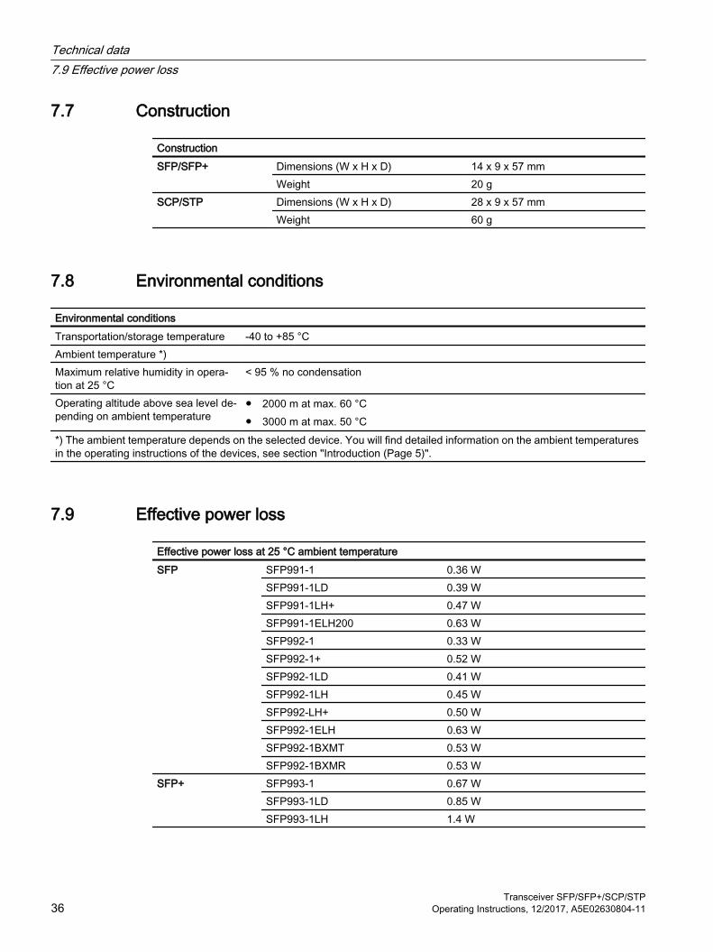
7.7 Construction
ConstructionSFP/SFP+ Dimensions (W x H x D) 14 x 9 x 57 mm
Weight 20 gSCP/STP Dimensions (W x H x D) 28 x 9 x 57 mm
Weight 60 g
7.8 Environmental conditions
Environmental conditionsTransportation/storage temperature -40 to +85 °CAmbient temperature *) Maximum relative humidity in opera‐tion at 25 °C
< 95 % no condensation
Operating altitude above sea level de‐pending on ambient temperature
● 2000 m at max. 60 °C● 3000 m at max. 50 °C
*) The ambient temperature depends on the selected device. You will find detailed information on the ambient temperatures in the operating instructions of the devices, see section "Introduction (Page 5)".
7.9 Effective power loss
Effective power loss at 25 °C ambient temperatureSFP SFP991-1 0.36 W
SFP991-1LD 0.39 WSFP991-1LH+ 0.47 WSFP991-1ELH200 0.63 WSFP992-1 0.33 WSFP992-1+ 0.52 WSFP992-1LD 0.41 WSFP992-1LH 0.45 WSFP992-LH+ 0.50 WSFP992-1ELH 0.63 WSFP992-1BXMT 0.53 WSFP992-1BXMR 0.53 W
SFP+ SFP993-1 0.67 WSFP993-1LD 0.85 WSFP993-1LH 1.4 W
Technical data7.9 Effective power loss
Transceiver SFP/SFP+/SCP/STP36 Operating Instructions, 12/2017, A5E02630804-11

Effective power loss at 25 °C ambient temperatureSCP SCP992-1 0.33 W
SCP992-1LD 0.41 WSTP STP991-1 0.36 W
STP991-1LD 0.39 W
NoteFusing of transceivers
The pluggable transceivers (SFP/SFP+/SCP/STP) do not have fuses. The fuse is in the modular device.
NoteSignaling contact and media modules
The SFP transceivers do not have a signaling contact. The signaling contact is on the modular device.
7.10 MTBF (Mean Time Between Failure)
MTBFSFP SFP991-1 > 490 years
SFP991-1LD > 490 yearsSFP991-1LH+ > 420 yearsSFP991-1ELH200 > 380 yearsSFP992-1 > 670 yearsSFP992-1+ > 227 yearsSFP992-1LD > 600 yearsSFP992-1LH > 490 yearsSFP992-1LH+ > 490 yearsSFP992-1ELH > 430 yearsSFP992-1BXMT > 340 yearsSFP992-1BXMR > 340 years
SFP+ SFP993-1 > 1100 yearsSFP993-1LD > 850 yearsSFP993-1LH > 300 years
SCP SCP992-1 > 670 yearsSCP992-1LD > 600 years
STP STP991-1 > 490 yearsSTP991-1LD > 490 years
Technical data7.10 MTBF (Mean Time Between Failure)
Transceiver SFP/SFP+/SCP/STPOperating Instructions, 12/2017, A5E02630804-11 37

Technical data7.10 MTBF (Mean Time Between Failure)
Transceiver SFP/SFP+/SCP/STP38 Operating Instructions, 12/2017, A5E02630804-11

Dimension drawings 88.1 SFP dimension drawing
Front and top view, side view (left/right) and view from below
57
14
914
Dimensions are specified in mm.
Transceiver SFP/SFP+/SCP/STPOperating Instructions, 12/2017, A5E02630804-11 39

8.2 SFP+ dimension drawing
Front and top view, side view (left/right) and view from below
57
14
14
9
Dimensions are specified in mm.
Dimension drawings8.2 SFP+ dimension drawing
Transceiver SFP/SFP+/SCP/STP40 Operating Instructions, 12/2017, A5E02630804-11

8.3 SCP dimension drawingFront and top view, side view (left/right) and view from below
Dimensions are specified in mm.
Dimension drawings8.3 SCP dimension drawing
Transceiver SFP/SFP+/SCP/STPOperating Instructions, 12/2017, A5E02630804-11 41

8.4 STP dimension drawingFront and top view, side view (left/right) and view from below
Dimensions are specified in mm.
Dimension drawings8.4 STP dimension drawing
Transceiver SFP/SFP+/SCP/STP42 Operating Instructions, 12/2017, A5E02630804-11

Approvals 9The SIMATIC NET products described in these Operating Instructions have the approvals listed below.
NoteIssued approvals on the type plate of the device
The specified approvals apply only when the corresponding mark is printed on the product. You can check which of the following approvals have been granted for your product by the markings on the type plate.
EC directivesSIMATIC NET products meet the requirements and aims of the following EC directives.
EMC directive (electromagnetic compatibility)The SIMATIC NET products described in these operating instructions meet the requirements of EC directive 2004/108/EC "Electromagnetic Compatibility" for the following areas of application:
Field of application RequirementsEmission Immunity to interference
Industry EN 61000-6-4 : 2007 EN 61000-6-2 : 2005
EC declaration of conformityThe SIMATIC NET products described in these operating instructions meet the requirements and safety objectives of the following EC directives and comply with the harmonized European standards (EN) which are published in the official documentation of the European Union.
● 2014/34/EU (ATEX explosion protection directive)Directive of the European Parliament and the Council of 26 February 2014 on the approximation of the laws of the member states concerning equipment and protective systems intended for use in potentially explosive atmospheres, official journal of the EU L96, 29/03/2014, pages. 309-356
● 2014/30/EU (EMC)EMC directive of the European Parliament and of the Council of February 26, 2014 on the approximation of the laws of the member states relating to electromagnetic compatibility; official journal of the EU L96, 29/03/2014, pages. 79-106
● 2011/65/EU (RoHS)Directive of the European Parliament and of the Council of 8 June 2011 on the restriction of the use of certain hazardous substances in electrical and electronic equipment
Transceiver SFP/SFP+/SCP/STPOperating Instructions, 12/2017, A5E02630804-11 43

You will find the EC declaration of conformity for these products on the Internet pages of Siemens Industry Online Support (https://support.industry.siemens.com/cs/ww/en/ps/15273/cert).
The EC Declaration of Conformity is available for all responsible authorities at:
Siemens Aktiengesellschaft
Division Process Industries and DrivesProcess AutomationDE-76181 KarlsruheGermany
Machinery directiveThe product is a component in compliance with the EC Machinery Directive 2006/42//EEC. According to the machinery directive, we are obliged to point out that the product described is intended solely for installation in a machine.
Before the final product can be put into operation, it must be tested to ensure that it conforms with the directive 2006/42/EEC.
NoteNote for the manufacturers of machines
This product is not a machine in the sense of the EC Machinery Directive. There is therefore no declaration of conformity relating to the EC Machinery Directive 2006/42/EEC for this product.
ATEX (explosion protection directive)
WARNING
When using SIMATIC NET products in hazardous area zone 2, make absolutely sure that the associated conditions in the following document are adhered to:
"SIMATIC NET Product Information Use of subasseblies/modules in a Zone 2 Hazardous Area".
You will find this document● on the data medium that ships with some devices.● on the Internet pages of Siemens Industry Online Support (https://
support.industry.siemens.com/cs/ww/en/ps).
Enter the document identification number C234 as the search term.
The SIMATIC NET products meet the requirements of the EC directive 94/9/EC "Equipment and Protective Devices for Use in Potentially Explosive Atmospheres”. and as of 20.04.2016 the EC directive 2014/34/EU.
ATEX classification:
II 3 G Ex nA IIC T4 Gc
Approvals
Transceiver SFP/SFP+/SCP/STP44 Operating Instructions, 12/2017, A5E02630804-11

KEMA 07ATEX0145 X
The products meet the requirements of the following standards:
● EN 60079-15 (electrical apparatus for potentially explosive atmospheres; Type of protection "n")
● EN 60079-0 (Explosive atmospheres - Part 0: Equipment - General requirements)
You will find the current versions of the standards in the currently valid ATEX certificates.
IECExThe SIMATIC NET products meet the requirements of explosion protection according to IECEx.
IECEx classification:
Ex nA IIC T4 Gc
DEK 14.0025X
The products meet the requirements of the following standards:
● IEC 60079-15 (Explosive atmospheres - Part 15: Equipment protection by type of protection "n")
● IEC 60079-0 (Explosive atmospheres - Part 0: Equipment - General requirements)
You will find the current versions of the standards in the currently valid IECEx certificates.
Note
The transceivers do not have a UL listing but a c-UR-us approval (component approval).
RCMThe product meets the requirements of the AS/NZS 2064 standard (Class A).
MSIP 요구사항 ‑ For Korea onlyA급 기기(업무용 방송통신기자재)
이 기기는 업무용(A급) 전자파 적합기기로서 판매자 또는 사용자는 이 점을 주의하시기 바라며, 가정 외의 지역에서 사용하는것을 목적으로 합니다.
Marking for the customs unionEAC (Eurasian Conformity)
Customs union of Russia, Belarus and Kazakhstan
Declaration of the conformity according to the technical regulations of the customs union (TR CU)
Approvals
Transceiver SFP/SFP+/SCP/STPOperating Instructions, 12/2017, A5E02630804-11 45

FDA and IEC marksThe following devices meet the FDA and IEC requirements listed below:
Pluggable transceiv‐er
Type Fulfills FDA and IEC requirements
SFP SFP991-1 CLASS 1 LASER PRODUCTSFP991-1LD CLASS 1 LASER PRODUCTSFP991-1LH+ CLASS 1 LASER PRODUCTSFP991-1ELH200 CLASS 1 LASER PRODUCTSFP992-1 CLASS 1 LASER PRODUCTSFP992-1+ CLASS 1 LASER PRODUCTSFP992-1LD CLASS 1 LASER PRODUCTSFP992-1LH CLASS 1 LASER PRODUCTSFP992-1LH+ CLASS 1 LASER PRODUCTSFP992-1ELH CLASS 1 LASER PRODUCTSFP992-1BXMT CLASS 1 LASER PRODUCTSFP992-1BXMR CLASS 1 LASER PRODUCT
SFP+ SFP993-1 CLASS 1 LASER PRODUCTSFP993-1LD CLASS 1 LASER PRODUCTSFP993-1LH CLASS 1 LASER PRODUCT
SCP SCP992-1 CLASS 1 LASER PRODUCTSCP992-1LD CLASS 1 LASER PRODUCT
STP STP991-1 CLASS 1 LASER PRODUCTSTP991-1LD CLASS 1 LASER PRODUCT
Figure 9-1 FDA and IEC approvals
Approvals
Transceiver SFP/SFP+/SCP/STP46 Operating Instructions, 12/2017, A5E02630804-11

Mechanical stability (in operation)
Pluggable trans‐ceiver
Type IEC 60068-2-6 vibration IEC 60068-2-27 shock5 – 9 Hz: 3.5 mm9 – 150 Hz: 1 g1 octave/min, 20 sweeps
15 g, 11 ms duration6 shocks per axis
SFP SFP991-1 ● ●SFP991-1LD ● ●SFP991-1LH+ ● ●SFP991-1ELH200 ● ●SFP992-1 ● ●SFP992-1+ ● ●SFP992-1LD ● ●SFP992-1LH ● ●SFP992-1LH+ ● ●SFP992-1ELH ● ●SFP992-1BXMT ● ●SFP992-1BXMR ● ●
SFP+ SFP993-1 ● ●SFP993-1LD ● ●SFP993-1LH ● ●
SCP SCP992-1 ● ●SCP992-1LD ● ●
STP STP991-1 ● ●STP991-1LD ● ●
Installation guidelinesThe devices meet the requirements if you adhere to the installation and safety instructions contained in this documentation and in the following documentation when installing and operating the devices.
● "Industrial Ethernet / PROFINET Industrial Ethernet" System Manual (https://support.industry.siemens.com/cs/ww/en/view/84922825)
● "Industrial Ethernet / PROFINET - Passive Network Components" System Manual (https://support.industry.siemens.com/cs/ww/en/view/27069465)
● "EMC Installation Guidelines" configuration manual (https://support.industry.siemens.com/cs/ww/en/view/60612658)
WARNING
Personal injury and property damage can occur
The installation of expansions that are not approved for SIMATIC NET products or their target systems may violate the requirements and regulations for safety and electromagnetic compatibility.
Only use expansions that are approved for the system.
Approvals
Transceiver SFP/SFP+/SCP/STPOperating Instructions, 12/2017, A5E02630804-11 47

Note
The test was performed with a device and a connected communications partner that also meets the requirements of the standards listed above.
When operating the device with a communications partner that does not comply with these standards, adherence to the corresponding values cannot be guaranteed.
Approvals
Transceiver SFP/SFP+/SCP/STP48 Operating Instructions, 12/2017, A5E02630804-11

Index
AArticle number, 12, 13, 14Attenuation, 35Attenuator, 35
FFiber monitoring, 12
GGlossary, 6
PPluggable transceiver
Inserting, 18, 20Notes on deinstallation, 21Removing, 21, 22SCP, 14STP, 14
Pluggable transceiver slot, 21Power supply, 23
SSafety instructions, 9SCP transceiver, 14SCP/STP transceiver
Notes on installation, 18Sealing plug, 21SFP/SFP+ transceivers
Notes on installation, 15SFP+ transceiver, 13SIMATIC NET glossary, 6SIMATIC NET manual, 5STP transceiver, 14System manual, 5, 47
TType designation, 11
Transceiver SFP/SFP+/SCP/STPOperating Instructions, 12/2017, A5E02630804-11 49

Index
Transceiver SFP/SFP+/SCP/STP50 Operating Instructions, 12/2017, A5E02630804-11