safety interlock switches cm series - valinonline.com · expand your system by using the cm-se...
TRANSCRIPT

G
G63 www.sti.com/info
Conforms to EN292, EN60204-1, EN954-1, EN1088, EN60947-5-3, EN947-5-3, EN50081, EN50082, EN61000-6-2, ISO 13849-1 UL and C-UL listed, TUV certified
Most Diverse and Flexible Line of Coded Magnetic Safety Interlock Switches and Controllers • CombinedoorswitchmonitoringandE-stopmonitoringbyusing theCM-S41controller
• MonitorissingleswitchtoCAT4withtheCM-S30controller • MonitormultipleswitchestoCAT3usingCM-S4orCM-S30
controllers • Monitoringmultipleswitchesonindividualchannelscanbe achievedbyusingtheCM-S21orCM-S41controllers.Easily expandyoursystembyusingtheCM-SEexpansionmodule.
• AllCMswitchesareratedIP67 • Stainlesssteelswitchesareavailableforharshenvironments • ARapidDeliveryProduct:Selectmodelsareavailablefor shipmenttodayorwithin3to5days
Safety Interlock Switches
CM Series CM
Description
TheCMseriesofcontrollersandcodedmagneticswitches offersthemostflexibilityandwidestrangeofoptionsavailable. TheCMseriesiscomprisedoftwobasictechnologies.
Controller Technologies 2-Wire Single Channel Controllers TheCM-S41andCM-S21controllersmonitorthe2-wire
magneticallycodedswitches.TheCM-S41andCM-S21control-lersuseapatentedtechnologywhichallowsthemtomonitorthe 2-wireorsinglechannelswitchesuptoCategory3.Theabilityto monitorjustasinglechannelenablestheCM-S41andCM-S21to easilymonitormultipleswitchesandprovideindividualstatusof eachchannel.Bothofthesecontrollersarecompatiblewiththe CM-SEexpansionmodule.
Dual Channel Controllers TheCM-S4andCM-S30controllersaredesignedtomonitor
conventionalread-style,magnetically-codedswitcheswith1N/O +1N/Ccontacts.TheCM-S4controllercanmonitoruptofour switchestocategory3.TheCM-S4controlleroffersstatusindica-tionforeachindividualswitch.TheCM-S30controllercanmonitor oneswitchtocategory4,ortwoswitchestocategory3.TheCM-S30controlunitiscapableofmonitoringupto30conventional readstyleswitchesinseries,butdoesnotconformtocategory3 whenusedwithmorethantwoswitches.
Switch Categories TheCMseriesofswitchesareallmagneticallycoded.
TheCMseriesofswitchesfallintothreemaincategories: 1.2-wireCodedMagnetic 2.ConventionalReadStyle1N/C+1N/Ocontacts 3.UniversalReadStyle2N/C+1N/Ocontacts
The2-wireCodedMagneticSwitchesareonlycompatiblewith theCM-S21,CM-S41andCM-SEcontrolunitsandexpansion module.TheConventionalReadStyleSwitchesarecompatible withtheCM-S4andCM-S30controllers.TheUniversalRead StyleSwitchesareuniqueindesign,allthreecontactsarerated forsafety.ThismeansthatUniversalReadStyleswitchescan beusedwiththeCM-S4orCM-S30Controllers,orconventional safetymonitoringrelayssuchastheG9SA,SR103orG9SX-AD, -BC.ThisallowstheUniversalReadStyleSwitchestoberunin serieswithE-stopswitchesorothermechanicaldoorswitches. Typicallyacategory2ratingwouldbeappliedtoasystemthat incorporatesmultipleswitcheswiredinseriestoastandardsafety monitoringrelay.Ariskassessmentshouldalwaysbeperformed byproperlytrainedandauthorizedpersonnel.
For full product information, visit www.sti.com. Use the SpeedSpec Code or scan the QR Code for quick access to the specific web page.
Select models are available for Rapid Delivery. Visit this product on www.sti.com for details..
R
C US
G
G64 www.sti.com/info
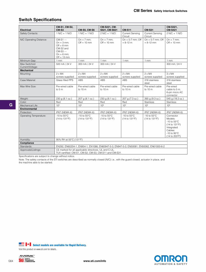
Switch Specifications
Electrical CM-S1, CM-S2, CM-S3 CM-S5, CM-S6
CM-S221, CM-S521, CM-S621 CM-S11 CM-S31
CM-S321, CM-S421
SafetyContacts: 1N/C+1N/O 1N/C+1N/O 2N/C+1N/O CurrentSensing Circuit
CurrentSensing Circuit
2N/C+1N/O
N/COperatingDistance: CM-S1— On = 3 mm; Off = 8 mm CM-S2and CM-S3— On = 6 mm; Off = 13 mm
On = 7 mm; Off = 10 mm
On = 7 mm; Off = 10 mm
On = 5-7 mm; Off = 8-12 m
On = 5-7 mm; Off = 8-12 mm
On = 7 mm; Off = 10 mm
MinimumGap: 1 mm 1 mm 1 mm 1 mm 1 mm 1 mm MaxSwitched Current/Voltage:
500mA/24V 300mA/24V 300mA/24V 300mA/24V
Mechanical Mounting: 2xM4
screwssupplied 2xM4 screwssupplied
2xM4 screwssupplied
2xM4 screwssupplied
2xM4 screwssupplied
3xM4 screwssupplied
CaseMaterial: GlassfilledPPS ABS ABS ABS 316 stainless steel
316 stainless steel
MaxWireSize: Pre-wiredcable to 5 m
Pre-wiredcable to 10 m
Pre-wiredcable to 10 m
Pre-wiredcable to 10 m
Pre-wiredcable to 10 m
Pre-wired cableto5m, 6-pinmicroAC connector
Weight: 230g(8.1oz.) 207g(8.1oz.) 230g(8.1oz.) 207g(7.3oz.) 265g(9.3oz.) 545g(19.2oz.) Color: Red Red Red Red Stainless Stainless MechanicalLife: 106 106 106 106 106 106
Environmental Protection: IP67(NEMA6) IP67(NEMA6) IP67(NEMA6) IP67(NEMA6) IP67(NEMA6) IP67(NEMA6) OperatingTemperature: -10 to 55°C
(14to131°F) -10 to 55°C (14to131°F)
-10 to 55°C (14to131°F)
-10 to 55°C (14to131°F)
-10 to 55°C (14to131°F)
Connector Models: -10 to 55°C (14to131°F) Integrated Cables: -10 to 95°C (14to203°F)
Humidity: 95%RHat55°C(131°F) Compliance Standards: EN292, EN60204-1, EN954-1, EN1088, EN60947-5-3, EN947-5-3, EN50081, EN50082, EN61000-6-2 Approvals/Listings: CEmarkedforallapplicabledirectives,ULandC-UL.
TUVcertified:CM-S1,CM-S2,CM-S3,CM-S11andCM-S31. Specificationsaresubjecttochangewithoutnotice. Note:ThesafetycontactsoftheSTIswitchesaredescribedasnormallyclosed(N/C)i.e.,withtheguardclosed,actuatorinplace,and themachineabletobestarted.
CM Series Safety Interlock Switches
Select models are available for Rapid Delivery. Visit this product on www.sti.com for details..

G
G65 www.sti.com/info
CM Series Safety Interlock Switches
Control Unit Specifications
Electrical CM-S4 CM-S30 CM-S41, CM-S21 & CM-SE PowerSupply: 24VAC/DC±10% 24VAC/DC±10% CM-S41—24VAC/DC,110/230VAC
CM-S21&CM-SE—24VAC/DC
PowerConsumption: 2.4VAtypical,0.25Aquickacting 120mA CM-S41—6VA; CM-S21&CM-SE—3VA
InputFuse: 500mAresetable 750mAresetable 500mAresetable
SafetyInputs: 1N/O+1N/C 1N/O+1N/C CM-S41— 4CM-S11orCM-S31switches CM-S21— 2CM-S11orCM-S31switches CM-SE—5CM-S11orCM-S31switches
MaxCableLength: — — 100m(328ft.) MaxInputResistance: Contactfactory Contactfactory Contactfactory
RelayOutputs: 1N/Osafety+1N/Oaux. 2N/Osafety+1N/Caux. CM-S41&CM-S21—2N/O; CM-SE—N/A
MaxSwitchedCurrent/Voltage: 4A/24VAC/DC 3A/24VAC/DC 4A/230VAC;2A/24VDC(resistive) MinSwitchedCurrent/Voltage: 4mA/12V 4mA/12V 10V/10mA
ImpulseWithstandVoltage: 250 V 250 V 250 V MaxDrop-OutTime: 18 ms 18 ms Deactivationbysensor13mS
MaxOutputFuse: 4Aquickacting 4Aquickacting AC=5A;DC=2.5A;quickacting
ResetMode: Automatic Automatic/Manual,monitored Monitoredmanualorautomatic
ExternalDeviceMonitoring: N/CloopbetweenY1andY2 BetweenY1,Y2,Y3 N/CloopbetweenX1andX2 Mechanical Mounting: 35mm(1.38in.)DINrail 35mm(1.38in.)DINrail 35mm(1.38in.)DINrail CaseMaterial: PolyamidPA6.6 PolyamidPA6.6 Polycarbonate
MaxWireSize: 2x2.5mm2(12AWG) 1x2.5mm2(14AWG) 1x2.5mm2 stranded, 1 x 4 mm2 solid Weight: 240g(8.5oz.) 230g(8.1oz.) CM-S41—575g(20.3oz.)
CM-S21—183g(6.5oz.) CM-SE—135g(4.8oz.)
Color: Grey Red/Grey Red
Indication: U:Green=On OutputsOpen:Red=On OutputsClosed:Green=On D11,D12,D21,D22:Green=Gateclosed D31,D32,D41,D42:Red=Gateopen
Green=PowerOn Green = K1 On Green = K2 On
Power=Red OutputsClosed:Green=On OutputsOpen:NoLight=Off GateClosed:Yellow=On GateOpen:NoLight=Off
MechanicalLife: 3 x 10⁷ 1 x 10⁷ 1 x 10⁶
Environmental Protection: HousingIP40,TerminalsIP20 HousingIP40,TerminalsIP20 HousingIP40,TerminalsIP20
OperatingTemperature: 0to50°C(32to122°F) 0to55°C(32to131°F) 10to55°C(50to131°F) Humidity: 95% 93% 85% Compliance Standards: EN292, EN60204-1, ISO 13849-1, EN1088, EN60947-5-3, EN947-5-3,
EN50081, EN50082, EN61000-6-2 EN292, EN60204-1, EN954-1,EN1088, EN60947-5-3, EN947-5-3, EN50081, EN50082, EN61000-6-2
Approvals/Listings: CEmarkedforallapplicabledirectives,ULandC-UL,TUV(TUVpendingforCM-S30) SafetyCategory: Cat3perEN954-1
(internaloperation) Cat4perISO13894-1 (internaloperation)
Cat3perEN954-1 (internaloperation)
Specificationsaresubjecttochangewithoutnotice. Note:ThesafetycontactsoftheSTIswitchesaredescribedasnormallyclosed(N/C)i.e.,withtheguardclosed,actuatorinplace,andthemachineableto bestarted.
Select models are available for Rapid Delivery. Visit this product on www.sti.com for details..
G
www.sti.com/info
ISIS-4 or ISIS-2CONTROL UNIT
Connect the ISIS-EBus connection to
CM Series Safety Interlock Switches
Applications
2-Wire Single Channel Controllers
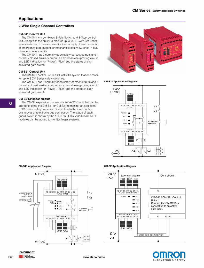
CM-S41 Control Unit TheCM-S41isacombinedSafetySwitchandE-Stopcontrol
unit.Alongwiththeabilitytomonitoruptofour,2-wireCMSeries safetyswitches,itcanalsomonitorthenormallyclosedcontacts ofemergencystopbuttonsormechanicalsafetyswitchesindual channelcontrolcircuits. TheCM-S41has2normallyopensafetycontactoutputsand1
normallyclosedauxiliaryoutput,anexternalreset/provingcircuit andLEDindicationfor“Power”,“Run”andthestatusofeach activatedgateswitch.
CM-S21 Control Unit TheCM-S21controlunitisa24VAC/DCsystemthatcanmoni
torupto2CMSeriessafetyswitches. TheCM-S21has2normallyopensafetycontactoutputsand1 CM-S21 Application Diagram
normallyclosedauxiliaryoutput,anexternalreset/provingcircuit andLEDindicationfor“Power”,“Run”andthestatusofeach activatedgateswitch.
CM-SE Extender Module TheCM-SEexpansionmoduleisa24VAC/DCunitthatcanbe
addedtoeithertheCM-S41orCM-S21tomonitoranadditional 5CMSeriessafetyswtiches.Connectiontothemaincontrol unitisbyasimple2-wirebusconnection.Thestatusofeach guardswitchisshownbytheYELLOWLED’s.AdditionalCMS-E modulescanbeaddedtomonitorlargersystems.
GATE 2
A1 X1 BL DR 31 13 23
A2 X2 BL DR 32 14 24
GATE 1
GS2
GS1
K1 K2
K1
K2
24V (+ve)
0V (-ve)
K1
K2
F1
F2
POWER
IND 1
IND 2
RUN
MANUAL RE-SET
CM-S41 Application Diagram CM-SE Application Diagram
MECHANICAL K1 SAFETY
SWITCHESor K2
EMERGENCY STOP
RUN
POWER
GATE 4 GATE 3
4
3
2
1
GATE 4
GATE 3
GATE 2
DE-SELECT
A1 S13 S23 X1 BL DR BL DR 31 13 23
A2 S14 S24 X2 BL DR BL DR 32 14 24
GATE 2 GATE 1
GS3 GS4
GS1GS2
K1 K2
MANUAL RE-SET
L (+ve)
N (-ve)
K1
K2
F1
F2
A1 BLDR GATE 1
GS1
24 V +ve
0 V -ve
BLDR BLDR GATE 2 GATE 3
GS2 GS3
A2 BLDR GATE 4
GS4
BLDR BLDR GATE 5 BUS
GS5
IND 1
IND 2
IND 3
IND 4
IND 5
2-WIRE BUS CONNECTION
POWER
BL DR A2
A1
Extender Module Control Unit
CM-S41 / CM-S21 Control Units: Connect the CM-SE Bus connection to an active gate input.
G66

G
www.sti.com/info
CM Series Safety Interlock Switches
Applications (continued)
Dual Channel Controllers
CM-S4 Control Unit TheCM-S4controlleriscapableofmonitoringuptofour,
magneticallycodedswitcheswith1N/O+1N/Ccontactsupto category3accordingtoEN954-1.TheCM-S4hasadedicated dualchannelinputforeachswitchandhasLEDstatusindicators foreachchannel.TheCM-S4has1N/Osafetycontactand1N/O Auxcontact.ExternalDeviceMonitoring(EDM)isavailableusing Y1,Y2inputs.
CM-S30 Control Unit TheCM-S30controlleriscapableofmonitoringonemagneti
callycodedswitchwith1N/O+1N/Ccontactsuptocategory 4,ortwoswitchestocategory3accordingtoISO13489-1.The CM-S30controlunitiscapableofmonitoringupto30conventionalreadstyleswitchesinseries,butdoesnotconformtocategory 4whenusedwithmorethantwoswitches.TheCM-S30controller has2N/Osafetycontactsand1N/CAuxillarycontact.External DeviceMonitoring(EDM)isavailableusingY1,Y2inputs.
CM-S4 Application Diagram CM-S30 Application Diagram (Cat 3)
24VAC/DC 24VAC/DC
K1
K1
K2
K2
UB
D12
D12
D11 K1
control logic
READ HEAD 1
CHANNEL 1
CHANNEL 3 CHANNEL 4 FEEEDBACK LOOP
YE
A1 A2 1 2 3 4
GN WH BN
GN
RD
RD
RD
GN
CHANNEL 2
D21
OUT
GN ID
GN
D31 GN
D41 GN
D12
READ HEAD 2
READ HEAD 3 READ HEAD 4
MON
ITOR
ED A
UTO
REST
ART
YE
5 6 7 8
9 10 11 12 15 16 17 18 14 24Y1 Y2
13
GN WH BN
BN WH YE GN BN WH YE GN
N (0 Volt)
K2
K3
K4
23
D42
RDCM-S4
*23-24shouldnotbeusedassafetyoutput.
WH
K1
K1
K1 K2
UB
K1 K1 F2
K2
START/FEEDBACK LOOP
MONITORED AUTO RESTART
K3
CHANNEL 1
CHANNEL 21
BRN
YE
GN
N (0 Volt)
A1 A2 HL1
H73 H74 Y1 Y2 Y3 14 24 32
HL2 H22 13 23 31
WH
BRN
YE
GN
GN
GN GN
CM-S30
CM-S30 Application Diagram (Cat 4)
24VAC/DC
WH
A1 A2 HL1
K1
K1
K1 K2
UB
K1 K1 F2
K2
H73 H74 Y1 Y2 Y3 14 24 32
MONITORED AUTO RESTART
K3
CHANNEL 1
HL2 H22 13 23 31
BRN
YE
GN
READ
HEA
D 1
N (0 Volt)
START/ FEEDBACK LOOPCHANNEL 21
GN
GN GN
CMS-S30
Select models are available for Rapid Delivery. Visit this product on www.sti.com for details..
G67
CM-S11 Switch
CM-S31 SwitchG
G68 www.sti.com/info
CM Series Safety Interlock Switches
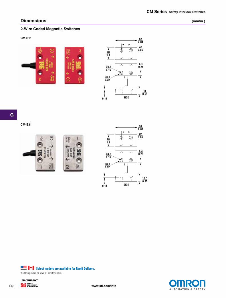
Dimensions (mm/in.)
2-Wire Coded Magnetic Switches
CM-S11
CM-S31
SIDE
Ø4.2 0.16
Ø8.1 0.32
3 0.11
14 0.55
6.4 0.25
28 1.1
52 2.04
22 0.86
SIDE
Ø4.2 0.16
Ø8.1 0.32
3 0.11
13.5 0.53
6.4 0.25
28 1.1
53 2.08
22 0.86
Select models are available for Rapid Delivery. Visit this product on www.sti.com for details..

CM-S3 Switch
CM-S2 Switch
CM-S1 Switch
G
G69 www.sti.com/info
CM Series Safety Interlock Switches
Conventional Read Style Switches
Dimensions (continued) (mm/in.)
CM-S1
CM-S2
CM-S3
1.5 0.06
20 0.79
36 1.42
8 0.310.34
0.013
42 1.65
Ø5.8 0.23
ca.
SW15 30.12
Center Offset m at s =
Son
SW40M30 x
2.5 0.1
2.5 0.1
Active Area Actuator
12 0.47 9.5
0.374
24.5 0.97 6
0.24
Ø5.5 0.22
13 0.51
2.5 0.1
67.5 2.66
87.5 3.44 6
0.24
NOTE: Actuator is same dimension as switch.
Ø5.8 0.23
ca.
0.34 0.013
42 1.65
2.5 0.1
2.5 0.1
3 0.12
Center Offset m at s =Active Area Actuator
Son
78 ± 1 3.07 ± 0.04
8.5 0.334
4.5 in
13 0.51
26.2 1.03
19.2 0.755
5 0.2
Ø5.8 0.23
2.5 0.1
2.5 0.1
3 0.12
0.34 0.013
42 1.65
36 1.42
22 0.87
7 0.28
Son
Center Offset m at s =
Active Area
Actuator
NOTE: Actuator is same dimension as switch.
ca.
Select models are available for Rapid Delivery. Visit this product on www.sti.com for details..

G
www.sti.com/info
CM Series Safety Interlock Switches
Dimensions (continued) (mm/in.)
Conventional Read Style Switches (continued)
CM-S5
CM-S5 and CM-S521
52.0 14.0 3.02.05 0.55 0.1222.0
0.87
28.0 1.10 SIDE VIEW
4.2 0.17 dia.
8.1 0.32 dia.
6.4 0.25
CM-S6
CM-S6 and CM-S621
19.0 4.9 0.75 0.19
82.5 68.0 3.25 2.68
19.0 0.75 4.9
0.19
82.5 3.25
73.0 2.87
19.0 0.75
19.0 0.75
7.2 7.25.05.0 0.28 0.280.200.20
SWITCH ACTUATOR
Select models are available for Rapid Delivery. Visit this product on www.sti.com for details..
G70

CM-S221 Switch
G
G71 www.sti.com/info
CM Series Safety Interlock Switches
Universal Read Style Switches
Dimensions (continued) (mm/in.)
CM-S221
For CM-S521 dimensions, please refer to the CM-S5 dimensions on the previous page. ✎
78.0 3.07
87.5 3.44
78.0 3.07
13.5 0.53
27.2 1.07
9.8 0.39
9.8 0.39
6.6 0.26
Switch
Actuator
13.5 0.53
27.2 1.07
CM-S321/CM-S421
60.0 2.36
79.0 3.11
33.0 1.30 16.0
0.6319.5 0.77
5.3 0.21
9.5 0.37 4.4
0.17
4.0 0.16
79.0 3.11
4.4 0.17
5.3 0.21
60.0 2.36
9.5 0.37
33.0 1.30
19.5 0.77
16.0 0.63
17.8 0.70
4.0 0.16
CM-S321 and CM-S421 Note: The CM-S321 includes a backing plate (not shown).
SWITCH ACTUATOR
with backing plate
17.8 0.70
with backing plate
CM-S521 CM-S621
For CM-S621 dimensions, please refer to the CM-S6 dimensions on the previous page. ✎

752.95
CM-S4
CM-S41
CM-S21/SE
752.95
742.91
742.91
843.3
1194.68
1194.68
22.50.88
22.50.88
843.3
1054.13
351.38
114.74.515
752.95
451.77
CM-S4
CM-S41
CM-S21/SE
For DIN rail
843.3
1194.68
22.50.88
22.50.88
843.3
1054.13
351.38
114.74.515
752.95
752.95
451.77
CM-S4
CM-S41
CM-S21/SE
For DIN rail
752.95
742.91
742.91
1194.68
G
G72 www.sti.com/info
CM Series Safety Interlock Switches
Dimensions (continued) (mm/in.)
Control Units
CM-S4
CM-S41
CM-S21 & CM-SE
105 4.13
35 1.38
114.7 4.515
75 2.95
45 1.77
For DIN rail
75 2.95
75 2.95
74 2.91
74 2.91
119 4.68
84 3.3
119 4.68
22.5 0.88
22.5 0.88
84 3.3
Select models are available for Rapid Delivery. Visit this product on www.sti.com for details..

CM-S30
G
www.sti.com/info
CM Series Safety Interlock Switches
Dimensions (continued) (mm/in.)
Control Units (continued)
CM-S30
DIN RAIL MOUNTING35 1.38
114 4.5
22.5 0.885
99 3.9
Select models are available for Rapid Delivery. Visit this product on www.sti.com for details..
G73

G
G74 www.sti.com/info
CM Series Safety Interlock Switches
Universal Mounting Brackets can be used with this product. See page G193 for details. ✎
Model Switch
Construction Contacts Wiring Entry Part No. Control Units for 2-Wire Switches CM-S21-24(24VAC/DC) 44536-0120 CM-S41-24(24VAC/DC) 44536-0140 CM-S41-110(110VACor230VAC) 44536-0141 CM-SE-24(24VAC/DC) 44536-0170 2-Wire Switches CM-S11-PC3 Plastic 2-wiresystem 3mcable 44536-1100 CM-S11-PC5 Plastic 2-wiresystem 5mcable 44536-1105 CM-S11-PC10 Plastic 2-wiresystem 10mcable 44536-1110 CM-S11-PCC5 Plastic 2-wiresystem connector+5mcable 44536-1159 CM-S31SC3 Stainless Steel 2-wiresystem 3mcable 44536-3100 CM-S31SC5 Stainless Steel 2-wiresystem 5mcable 44536-3105 CM-S31SCC5 Stainless Steel 2-wiresystem connector+5mcable 44536-3159 Control Units for 1 N/C + 1 N/O Reed Style Switches CM-S30(24VAC/DC) 44536-0030 CM-S4(24VAC/DC) 44536-0040 1 N/C + 1 N/O Reed Style Switches CM-S1PC3 Plastic 1N/C+1N/O 3mcable 44536-0100 CM-S1PC5 Plastic 1N/C+1N/O 5mcable 44536-0105 CM-S2PC3 Plastic 1N/C+1N/O 3mcable 44536-0200 CM-S2PC5 Plastic 1N/C+1N/O 5mcable 44536-0205 CM-S3PC3 Plastic 1N/C+1N/O 3mcable 44536-0300 CM-S3PC5 Plastic 1N/C+1N/O 5mcable 44536-0305 CM-S5PC5 Plastic 1N/C+1N/O 5mcable 44536-0505 CM-S5PC10 Plastic 1N/C+1N/O 10mcable 44536-0510 CM-S6PC5 Plastic 1N/C+1N/O 5mcable 44536-0605 CM-S6PC10 Plastic 1N/C+1N/O 10mcable 44536-0610 Universal Reed Style Switches (can be used with safety monitoring relays that accept 1N/C + 1N/O or 2NC switch contacts except the SR203, SR208, SR209) CAUTION! Universal reed switches may be operated with a coded or non-coded actuator when using 2 NC contacts with a safety monitoring relay. CM-S221PC5 Plastic 2N/C+1N/O 5mcable 44536-0221 CM-S221PCC5 Plastic 2N/C+1N/O connector+5mcable 44536-0225 CM-S221PCC Plastic 2N/C+1N/O nocable 44536-0226 CM-S521PC5 Plastic 2N/C+1N/O 5mcable 44536-0521 CM-S521PC10 Plastic 2N/C+1N/O 10mcable 44536-1521 CM-S621PC5 Plastic 2N/C+1N/O 5mcable 44536-0621 CM-S621PC10 Plastic 2N/C+1N/O 10mcable 44536-1621 CM-S321SC5 Stainless Steel 2N/C+1N/O 5mcable 44536-3221
CM-S321SCC5 Stainless Steel, backingplate
2N/C+1N/O M12connector +5mcable
44536-3229
CM-S321SCC Stainless Steel, backingplate
2N/C+1N/O M12connector,
nocable 44536-3220
CM-S421SC5 Stainless Steel, No backingplate
2N/C+1N/O 5mcable 44536-4221
CM-S421SCC5 Stainless Steel, No backingplate
2N/C+1N/O M12connector +5mcable
44536-4229
Recommended Safety Monitoring Relays for Universal Reed Style Switches CM-S4,CM-S30,G9SAseries,G9SX-AD,G9SX-BC,SRseries Spare Actuators/Accessories ReplacementActuatorforCM-S1,RedABSPlastic 44536-0710 ReplacementActuatorforCM-S2,RedABSPlastic 44536-0720 ReplacementActuatorforCM-S3,RedABSPlastic 44536-0730 ReplacementActuatorforCM-S5,CM-S521RedABSPlastic 44536-0750 ReplacementActuatorforCM-S6,CM-S621RedABSPlastic 44536-0760 ReplacementActuatorforCM-S11,RedABSPlastic 44536-0711 ReplacementActuatorforCM-S31,RedABSPlastic 44536-0731 ReplacementActuatorforCM-S221,RedABSPlastic 44536-0721 ReplacementActuatorforCM-S321,StainlessSteel,backingplate 44536-0741 ReplacementActuatorforCM-S421,StainlessSteel,NobackingPlate 44536-0751 MountingBracketforCM-S3 44536-0800
Ordering
Select models are available for Rapid Delivery. Visit this product on www.sti.com for details..