safety first magazine - issue 12 · the airbus safety magazine safety edition january 2013 issue 15...
TRANSCRIPT

The Airbus Safety Magazine
SafetyEdition January 2013
Issue 15
Subscription Form
SafetyContents:q The Golden Rules for Pilots
Moving from PNF to PM
q Airbus Crosswind Development and Certification
q The SMoke/FuMeS/AvNCS SMoke Procedure
q Post-Maintenance Foreign objects Damage (FoD) Prevention
q Corrosion: A Potential Safety Issue

The Airbus Safety Magazine
Subscription Form To be sent back to
AIRBUS FLIGHT SAFETY OFFICEFax: 33 (0)5 61 93 44 29Mail to: [email protected]
Name . . . . . . . . . . . . . . . . . . . . . . . . . . . . . . . . . . . . . . . . . . . . . . . . . . . . . . . . . . . . . . . . . . . . . . . . . . . . . . . . . . . . . . . . .
Surname . . . . . . . . . . . . . . . . . . . . . . . . . . . . . . . . . . . . . . . . . . . . . . . . . . . . . . . . . . . . . . . . . . . . . . . . . . . . . . . . . . . . . . .
Job title/Function. . . . . . . . . . . . . . . . . . . . . . . . . . . . . . . . . . . . . . . . . . . . . . . . . . . . . . . . . . . . . . . . . . . . . . . . . . . . . . . . .
Company/Organization. . . . . . . . . . . . . . . . . . . . . . . . . . . . . . . . . . . . . . . . . . . . . . . . . . . . . . . . . . . . . . . . . . . . . . . . . . . . .
Address . . . . . . . . . . . . . . . . . . . . . . . . . . . . . . . . . . . . . . . . . . . . . . . . . . . . . . . . . . . . . . . . . . . . . . . . . . . . . . . . . . . . . . . .
. . . . . . . . . . . . . . . . . . . . . . . . . . . . . . . . . . . . . . . . . . . . . . . . . . . . . . . . . . . . . . . . . . . . . . . . . . . . . . . . . . . . . . . . . . . . . .
. . . . . . . . . . . . . . . . . . . . . . . . . . . . . . . . . . . . . . . . . . . . . . . . . . . . . . . . . . . . . . . . . . . . . . . . . . . . . . . . . . . . . . . . . . . . . .
Post/Zip Code . . . . . . . . . . . . . . . . . . . . . . . . . . . . . . . . . . . . . . . . . . . . . . . . . . . . . . . . . . . . . . . . . . . . . . . . . . . . . . . . . . .
Country . . . . . . . . . . . . . . . . . . . . . . . . . . . . . . . . . . . . . . . . . . . . . . . . . . . . . . . . . . . . . . . . . . . . . . . . . . . . . . . . . . . . . . . .
Telephone . . . . . . . . . . . . . . . . . . . . . . . . . . . . . . . . . . . . . . . . . . . . . . . . . . . . . . . . . . . . . . . . . . . . . . . . . . . . . . . . . . . . . .
Cell phone . . . . . . . . . . . . . . . . . . . . . . . . . . . . . . . . . . . . . . . . . . . . . . . . . . . . . . . . . . . . . . . . . . . . . . . . . . . . . . . . . . . . . .
Fax . . . . . . . . . . . . . . . . . . . . . . . . . . . . . . . . . . . . . . . . . . . . . . . . . . . . . . . . . . . . . . . . . . . . . . . . . . . . . . . . . . . . . . . . . . .
E-mail . . . . . . . . . . . . . . . . . . . . . . . . . . . . . . . . . . . . . . . . . . . . . . . . . . . . . . . . . . . . . . . . . . . . . . . . . . . . . . . . . . . . . . . . . . . . . . . . . . (Mandatory for both digital and paper copies)
Please send me the digital copy* P
Please send me the paper copy* P (Please note that paper copies will only be forwarded to professional addresses)
* Please tick the appropriate case
Safety
Safety FirstThe Airbus Safety Magazine
For the enhancement of safe flight through
increased knowledge and communications
Safety First is published by the Flight Safety Department of Air-bus. It is a source of specialist safe-ty information for the restricted use of flight and ground crew members who fly and maintain Airbus air-craft. It is also distributed to other selected organisations.
Material for publication is obtained from multiple sources and includes selected informa-tion from the Airbus Flight Safety Confidential Reporting System, incident and accident investiga-tion reports, system tests and flight tests. Material is also ob-tained from sources within the airline industry, studies and re-ports from government agencies and other aviation sources.
All articles in Safety First are present-ed for information only and are not intended to replace ICAO guidelines, standards or recommended practices, operator-mandated requirements or technical orders. The contents do not supersede any requirements mand ated by the State of Registry of the Opera-tor’s aircraft or supersede or amend any Airbus type-specific AFM, AMM, FCOM, MEL documentation or any other approved documentation.
Articles may be reprinted without permission, except where copy-right source is indicated, but with acknowledgement to Airbus. Where Airbus is not the author, the con-tents of the article do not necessarily reflect the views of Airbus, neither do they indicate Company policy.
Contributions, comment and feed-back are welcome. For technical reasons the editors may be required to make editorial changes to manu-scripts, however every effort will be made to preserve the intended meaning of the original. Enquiries related to this publication should be addressed to:
AirbusProduct Safety department (GS)1, rond point Maurice Bellonte31707 Blagnac Cedex - FranceContact: Nils FAYAUDE-mail: [email protected]: +33(0)5 61 93 44 29
Safety First, #15 February 2013. Safety First is published by Airbus S.A.S. - 1, rond point Maurice Bellonte - 31707 Blagnac Cedex/France. Editor: Yannick Malinge, Chief Product Safety Officer, Nils Fayaud, Director Product Safety Information. Concept Design by Airbus Multi Media Support Ref. 20130248. Computer Graphic by Quat’coul. Copyright: GS 420.1329 Issue 15. Photos copyright Airbus. Photos by ExM Company, Baldur Sveinsson. Printed in France by Airbus Print Centre.
© Airbus S.A.S. 2013 – All rights reserved. Proprietary documents.
By taking delivery of this Brochure (hereafter “Brochure”), you accept on behalf of your company to
comply with the following guidelines:
3 No other intellectual property rights are granted by the delivery of this Brochure than the right to read
it, for the sole purpose of information.
3 This Brochure and its content shall not be modified and its illustrations and photos shall not be repro-
duced without prior written consent of Airbus.
3 This Brochure and the materials it contains shall not, in whole or in part, be sold, rented, or licensed
to any third party subject to payment.
This Brochure contains sensitive information that is correct at the time of going to press.
This information involves a number of factors that could change over time, effecting the true public
representation. Airbus assumes no obligation to update any information contained in this document or
with respect to the information described herein.
Airbus S.A.S. shall assume no liability for any damage in connection with the use of this Brochure and
of the materials it contains, even if Airbus S.A.S. has been advised of the likelihood of such damages.
A320 Winter operation in Yakutsk, Siberia
Issue 6, July 2008
– A320: Runway Overrun
– FCTL Check after EFCS Reset on Ground
– A320: Possible Consequence of VMO/MMO Exceedance
– A320: Prevention of Tailstrikes
– Low Fuel Situation Awareness
– Rudder Pedal Jam
– Why do Certain AMM Tasks Require Equipment Resets?
– Slide/raft Improvement
– Cabin Attendant Falling through the Avionics Bay Access Panel in Cockpit
Issue 5, December 2007
– New CFIT Event During Non Precision Approach
– A320: Tail Strike at Takeoff?
– Unreliable Speed
– Compliance to Operational Procedures
– The Future Air Navigation System FANS B
Issue 4, June 2007
– Operations Engineering Bulletin Reminder Function
– Avoiding High Speed Rejected Takeoffs Due to EGT Limit Exceedance
– Do you Know your ATC/TCAS Panel?
– Managing Hailstorms
– Introducing the Maintenance Briefing Notes
– A320: Dual hydraulic Loss
– Terrain Awareness and Warning Systems Operations Based on GPS Data
Issue 3, December 2006
– Dual Side Stick Inputs
– Trimmable Horizontal Stabilizer Damage
– Pitot Probes Obstruction on Ground
– A340: Thrust Reverser Unlocked
– Residual Cabin Pressure
– Cabin Operations Briefing Notes
– Hypoxia: An Invisible Enemy
Issue 2, September 2005
– Tailpipe or Engine Fire
– Managing Severe Turbulence
– Airbus Pilot Transition (ATP)
– Runway Excursions at Takeoff
Issue 1, January 2005
– Go Arounds in Addis-Ababa due to VOR Reception Problems
– The Importance of the Pre-flight Flight Control Check
– A320: In-flight Thrust Reverser Deployment
– Airbus Flight Safety Manager Handbook
– Flight Operations Briefing Notes
Previous Safety First Issues
2 Issue 15 | JANUARY 2013 Safety 23Issue 15 | JANUARY 2013The Airbus Safety Magazine

Editorial
ContentsFirstly, let me wish you all a Happy and Safe New year as we enter into 2013.
Our first magazine of this year presents to you a variety of articles covering a broad range of topics from good maintenance practices through to an insight into the crosswind certification of our aircraft.
It is sometimes true that we get what we hope for. It is even truer that we often get what we work hard to achieve. All industry Safety professionals have been working hard and successfully, to reduce the rate of accidents and major incidents. We have collectively reached the point where it is now difficult to see obvious and clear trends and “easy to fix” things with the tools we use today. Whilst a surface examination looks good, we also know that not far under that surface lie many threats and risks. We simply cannot allow the system to “relax”, nor can we ever afford to become complacent.
So how should we proceed? We must now dig deeper. We must “dig” into the growing volume of data that is available to us through our various data gathering programmes, be they LOSA, FOQA, FDA, FOA, ASIAS or whatever, and seek out the clues and the threads of information that will lead us to being able to prevent a future accident from happening.
Such an approach represents three challenges. Firstly, the ability to col-late, understand and act on so much data across the industry will require dedicated professionals with knowledge and determination to get at the answers. Secondly, and importantly, the industry wide collective challenge to face up to and address issues, which may appear to be minor in them-selves, but that may end up developing into major threats over time or when combined with other “minor” threats. Finally, but not least, even if significant progress has been made over the years, we have to find ways of further improving the sharing of lessons learned across boundaries.
We cannot go backwards, nor can we ease up for even a minute in our joint efforts to drive Safety to the next level.
May I therefore wish you all a successful year in your pursuit of increasing levels of Safety, in your area of our business during 2013.
Yannick MALINGE Chief Product Safety Officer
The Airbus Safety Magazine
Information ..................................................4
The Golden Rules for PilotsMoving from PNF to PM ...............................5 David OWENS
Airbus Crosswind Development and Certification ....................8Frank CHAPMAN
The SMoke/FuMeS/AvNCS SMoke Procedure .......................................12Peimann TOFIGHI-NIAKI
Post-Maintenance Foreign objects Damage (FoD) Prevention .............15François LEFEBVRE
Corrosion: A Potential Safety Issue............18David HILL
Yannick MALINGE Chief Product Safety Officer
3Issue 15 | January 2013The Airbus Safety Magazine

Magazine distribution
If you wish to subscribe to Safety First, please fill out the subscrip-tion form that you will find at the end of this issue.
Please note that the paper copies will only be forwarded to profes-sional addresses.
Your articles
As already said, this magazine is a tool to help share information.
We would appreciate articles from operators, that we can pass to other operators through the magazine.
If you have any inputs then please contact Nils Fayaud at:
e-mail: [email protected] fax : +33 (0) 5 61 93 44 29
The Flight Safety Conference provides an excellent forum for the exchange of information between Airbus and its customers. To ensure that we can have an open dialogue to promote flight safety across the fleet, we are unable to accept outside parties.
The formal invitations with informa-tion regarding registration and logistics, as well as the preliminary agenda have been sent to our customers in December 2012.
Another year has nearly passed since our last Flight Safety Conference in Berlin. All the Airbus people who were present enjoyed very much the oppor-tunity to network with our customers and to share ideas and news. It was the most successful conference yet both in terms of the numbers of people and airlines attending and in the feedback we received.
The 19th Flight Safety Conference will take place in Bangkok, Thailand, from the 18th to the 21st of March 2013.
For any information regarding invita-tions, please contact Mrs. Nuria Soler, email [email protected]
This year we will be looking at several interesting topics including the role of training in leveraging safety, unstable approaches, runway excursions and we will also include some more traditional reminders of issues that simply do not want to go away.
As always, we welcome presentations from our operators. You can participate as a speaker and share your ideas and experience for improving aviation safety.
If you have something you believe will benefit other operators and/or Airbus and if you are interested in being a speaker, please provide us with a brief abstract and a bio or resume at [email protected]
Safety Information on the Airbus websites
On the AirbusWorld website we are building up more safety information for you to use.
The present and previous issues of Safety First can be accessed to in the Flight Operations Community- Safe-ty and Operational Materials portal-, at https://w3.airbusworld.com
Other safety and operational exper-tise publications, like the Getting to Grips with…brochures, e-briefings etc…are regularly released as well in the Flight Operations Commu-nity at the above site.
If you do not yet have access rights, please contact your IT administrator.
Information
SAVE THE DATE19th
Bangkok, 18-21 March 2013
Flight Safety Hotline: +33 (0)6 29 80 86 66E-mail: [email protected]
Nils FAYAudDirector Product Safety Information
News
4 Issue 15 | January 2013 Safety
david OWENS Senior Director Training Policy
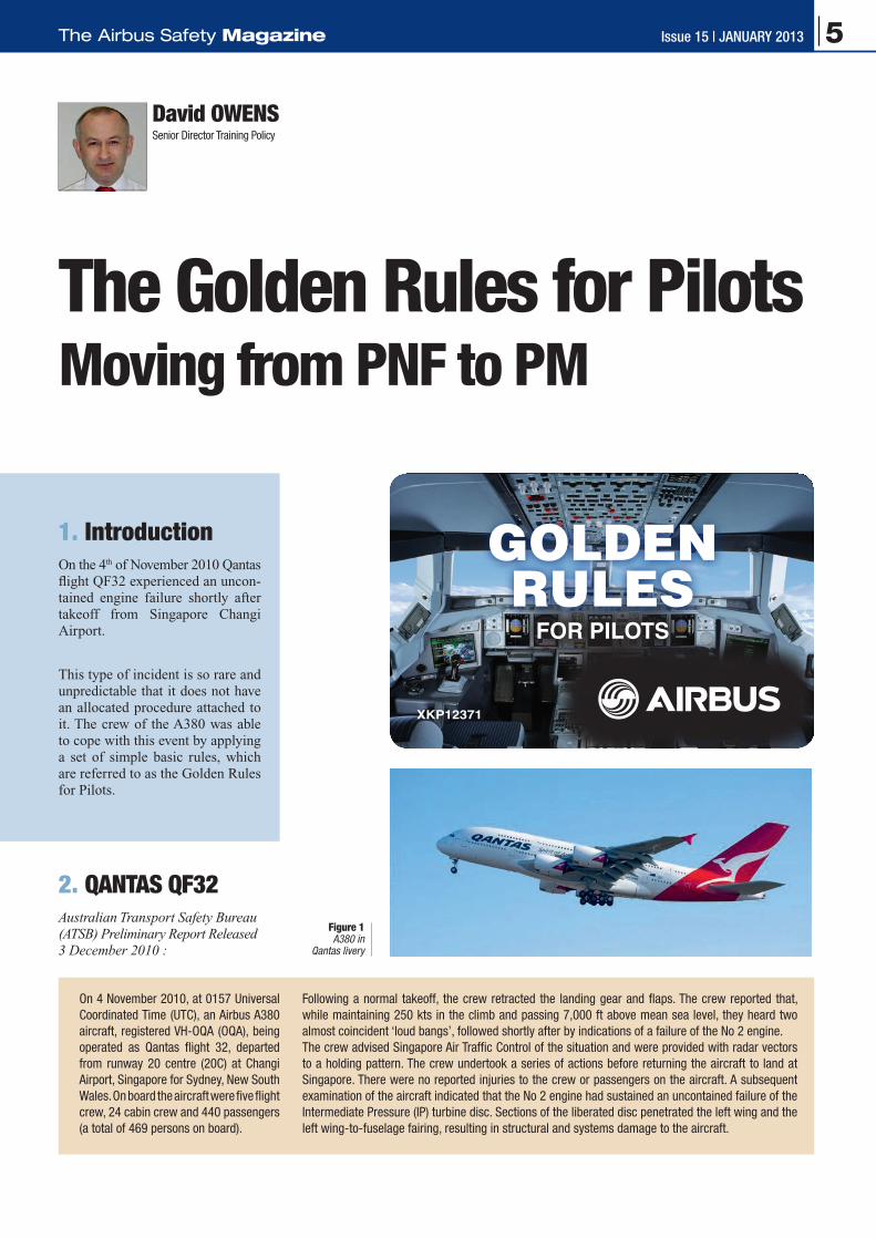
The Golden Rules for Pilots Moving from PNF to PM
1. IntroductionOn the 4th of November 2010 Qantas flight QF32 experienced an uncon-tained engine failure shortly after takeoff from Singapore Changi Airport.
This type of incident is so rare and unpredictable that it does not have an allocated procedure attached to it. The crew of the A380 was able to cope with this event by applying a set of simple basic rules, which are referred to as the Golden Rules for Pilots.
2. QANTAS QF32Australian Transport Safety Bureau (ATSB) Preliminary Report Released 3 December 2010 :
Following a normal takeoff, the crew retracted the landing gear and flaps. The crew reported that, while maintaining 250 kts in the climb and passing 7,000 ft above mean sea level, they heard two almost coincident ‘loud bangs’, followed shortly after by indications of a failure of the No 2 engine.The crew advised Singapore Air Traffic Control of the situation and were provided with radar vectors to a holding pattern. The crew undertook a series of actions before returning the aircraft to land at Singapore. There were no reported injuries to the crew or passengers on the aircraft. A subsequent examination of the aircraft indicated that the No 2 engine had sustained an uncontained failure of the Intermediate Pressure (IP) turbine disc. Sections of the liberated disc penetrated the left wing and the left wing-to-fuselage fairing, resulting in structural and systems damage to the aircraft.
FOR PILOTS
GOLDENRULES
XKP12371
On 4 November 2010, at 0157 Universal Coordinated Time (UTC), an Airbus A380 aircraft, registered VH-OQA (OQA), being operated as Qantas flight 32, departed from runway 20 centre (20C) at Changi Airport, Singapore for Sydney, New South Wales. On board the aircraft were five flight crew, 24 cabin crew and 440 passengers (a total of 469 persons on board).
Figure 1A380 in
Qantas livery
5Issue 15 | January 2013The Airbus Safety Magazine

In various interviews and state-ments the crew recognise that Crew Resource Management (CRM) gave them the ability to manage this chal-lenging event. They have spoken of “Synergy in Action”, the goal of CRM, and effective teamwork. They had plenty of fuel and therefore time and options. They acknowledge the impressive performance of the air-craft and their training and knowl-edge.
Figure 2QF32 n°2 engine after it sustained an uncontained failure of the Intermediate Pressure (IP) turbine disc
3. The Golden RulesOn the flight deck of QF32 that day Captain David Evans:
“From a training point of view it doesn’t matter what aeroplane you are flying, airmanship has to take over. In fact, Airbus has some Golden Rules which we all adhered to on the day – aviate, navigate and communicate – in that order.”
Royal Aeronautical Society, 6 December 2010
So, what are the Golden Rules? When should they be used and why?
The following four Golden Rules for Pilots are applicable to all nor-mal operations and any abnormal or emergency situations:
q Fly, navigate and communicate
q Use the appropriate level of automation at all times
q Understand the FMA at all times
q Take action if things do not go as expected.
3.1 Fly, navigate and communicate In this order and with appropriate tasksharing.
Just as the crew of QF 32 stated, the number one priority in any event and at all times is to fly the aircraft; this is the first Golden Rule.
Tasksharing should be adapted to the prevailing situation (i.e. task-sharing for hand flying or with the Auto Pilot engaged, task sharing for normal operation or for abnormal /emergency conditions) and tasks should be accomplished in accord-ance with the following priorities:
3.1.1 Fly
The Pilot Flying (PF) must focus on flying the aircraft by controlling and / or monitoring the pitch attitude, bank angle, airspeed, thrust, sideslip, heading etc. to capture and maintain the desired vertical and lateral flight path.
The Pilot Not Flying (PNF) must as-sist the Pilot Flying (PF) by actively monitoring all flight parameters and actively directing the attention of the PF to any excessive deviation.
Actively monitoring is a key mes-sage, we want to emphasize the
MONITORING role, which is why Airbus will be changing its docu-mentation over the next year to fully reflect and highlight the importance of Pilot Monitoring (PM). Wherever you see PNF, think PM!
Both pilots must remain focused on their task as PF or PM, not allow any-thing to distract them. This is what we mean by appropriate tasksharing.
Both pilots must maintain their Situ-ational Awareness and immediately resolve any uncertainty as a crew.
3.1.2 Navigate
Navigate can be summarized by the following three statements of situ-ational awareness:
q Know where you are
q Know where you should be
q Know where the weather, terrain and obstacles are.
6 Issue 15 | January 2013 Safety

To sum up:
q Monitor your FMA
q Announce your FMA
q Confirm your FMA
q Understand your FMA.
Finally, if any problems occur, refer to the Golden Gule number 4.
3.4 Take action if things do not go as expectedIf the aircraft does not follow the desired vertical or lateral flight path or the selected target, the crew should react without delay:
q By PF changing the level of automation:
•Frommanagedguidance to selected guidance, or
•Fromselectedguidance to manual flying; or
q By PM taking action, again we want to emphasize the PM func-tion and its essential role in flight safety:
•Questioning,andifthat is not enough
•Challenging,andifthat is still not enough
•Taking-over.
Never assume that any crewmember is aware of a particular threat, error or deviation and remember that inca-pacitation may be subtle; act before it is too late.
3.1.3 Communicate
Effective crew communication in-cludes communication between:
q The PF and the PM
q The flight crew and air traffic control
q The flight crew and the cabin crew or any other crew on-board
q The flight crew and ground crew.
Effective communication enables the sharing of goals and intentions and enhances situational awareness. To ensure positive communication, the flight crew must use standard phraseology and applicable callouts.
3.2 use the appropriate level of automation at all timesTo fly the aircraft the crew must comply with `Golden Rule number 2. On highly automated and inte-grated aircraft, several levels of au-tomation are available to perform a given task. The appropriate level of automation depends on the situation and task; taking into account the forecast or actual weather, any mal-function or crew incapacitation. Pi-lot judgment prevails for the choice of automation level, including the choice to fly manually.
q Understand the implication of the intended level of automation
q Select the intended level
q Confirm the aircraft responds as expected.
This leads us to Golden Rule number 3.
3.3 understand the FMA at all timesAny action on the FCU, or on the MCDU/KCCU, should be confirmed by crosschecking the corresponding annunciation or data on the PFD or ND.
At all times, the PF and PM should be aware of:
q The armed or engaged modes
q The guidance targets set
q The aircraft response in terms of attitude, speed and trajectory, etc
q Any mode transitions or reversions.
4. Conclusion
Apply these Golden Rules, use them always and support each other. The rules have been proven to make a difference. Just like the crew of Qantas QF 32, remember to always…
Fly the Aircraft …….. Fly the Aircraft…… Fly the Aircraft
Fly, navigate and communicate:In this order and with appropriate tasksharing
Use the appropriate level of automation at all times
Understand the FMA at all times
Take action if things do not go as expected
1
2
3
4
7Issue 15 | January 2013The Airbus Safety Magazine

Frank CHAPMANExperimental Test Pilot
Airbus Crosswind Development and Certification
2. HistoryHistorically, there were two methods of computation. For early certifica-tions, ATC tower winds were used to assess the level of crosswind ex-perienced at take-off and landing by flight test crews. This was done with an old fashioned anemometric recording system, registering wind values at a nominal 10 metres above ground level. This method evolved into using aircraft generated cross wind data by calculating the 10 m high wind using the difference be-tween the True Air Speed (TAS) vec-tor and the IRS computed Ground Speed (GS) vector during a 20 sec-ond period (+_10 sec) around take-off and landing. However, as natural IRS drift creates inaccuracy, this had to be taken into account. The drift value had to be periodically meas-ured in order to correct IRS Ground Speed. With the advent of Differen-tial GPS (DGPS) and more recent on-board instrumentation systems, the GS vector is now calculated using highly accurate data and, therefore, this correction is no longer necessary.
In the early days of certification, when using tower winds, the aver-
1. IntroductionThis article is one of a series in which we in Airbus try to create a bridge of information across the gap that exists between the manufacturers world of certification and the operators day to day environment.
At first glance, the issue of cross-wind certification for a large transport aircraft may seem simple. The fol-lowing is an extract from the EASA CS25.237(a) requirements:
A 90 deg cross component of wind velocity, demonstrated to be safe for take-off and landing must be estab-lished for dry runways and must be at least 20 kt or Vs MLW (1 g stall speed at Max Landing Weight) whichever is greater, except that it need not exceed 25 kt.
However, the subject is far more com-plicated than this short sentence may lead you to believe. So how do we deal with crosswinds during flight test and certification and what are the im-plications for operators?
age wind values were taken over the previous two minutes and the gust values over the previous 10 min period. Although ICAO considers wind gusts only if the peak value exceeds the two minute average by 10 kt, some airport weather services provide gust values lower than 10 kt. This method is still used for the broadcast of ATC tower winds. With the new flight test methodology, however, a much more representa-tive assessment of the aircraft capa-bility is achieved.
With the early Airbus certifications, we provided ‘Average plus Gust’ values in our FCOMs. However, it was felt by many that this format complicated the decision making process. Therefore, following a pe-riod of study beginning in 2004 we have now moved to a ‘Single Value, Gust Included’. This effectively means that a direct comparison of the maximum demonstrated value (provided by us, the manufacturer) can be made against the maximum value communicated by the Tower or ATIS, including the gust if an-nounced.
8 Issue 15 | January 2013 Safety

3. Maximum demonstrated Crosswind definitionToday, maximum demonstrated crosswind figuring in the FCOM is derived from the maximum cross-wind that has been encountered during the complete certification process and recorded in a particu-lar manner that has been agreed in conjunction with the authorities. It is not necessarily the maximum aircraft crosswind capability of the aircraft. It is purely based upon data recorded within the aircraft during the period of the certification process. Furthermore, it is often ob-served to be significantly different from the wind provided by ATC.
4. Flight Test MethodologyFirstly, wind data as experienced by the aircraft is collected for a period of +-10 sec either side of the take-off or landing. Then, we need to correlate this data to the established reference height of 10 metres. This is done with a mathematical cor-rection to the data, which varies with height to compensate for the boundary layer type effect near the surface.
A conservative proportion of the gusts observed are then added to the maximum steady crosswind wind value obtained. With this (gust added) value, we check that we have sufficient control authority in an equivalent steady wind case, based upon empirical flight control re-sponse data. If this is validated, we propose the value to the authorities for certification and inclusion in the AFM, for take-off and for landing.
On take-off, however, there is anoth-er effect, which can have a big influ-ence on crosswind limitation and/or take-off procedure: that of engine intake airflow distortion. This is covered in a separate analysis and many tests are carried out to ensure we provide a suitable operating en-velope for our engines during take-
off and landing. However, this may influence the final choice of dem-onstrated crosswind value provided and will almost certainly impact the procedure for applying take-off power. Manufacturers can choose to automatically limit engine regime for certain Ground Speeds if neces-sary, in much the same way that they sometimes automatically avoid cer-tain rpm ranges to avoid fan blade flutter for example. However, there is always a slight compromise, in order to ensure that take-off perfor-mance is not significantly reduced as a result. Limitations are imposed for the A380 and A340 500/600, for example, where the engine limita-tions are more penalizing than the demonstrated crosswind limitation and this is published in the FCOM limitations section.
5. Take-Off TechniqueEngine manufacturers design choice plays a large part in the ini-tial procedural approach to setting take-off thrust and, as mentioned above, may be crosswind limiting. Significant lateral control should be avoided during the take-off run in order to prevent extension of spoil-ers which will have a detrimental effect on performance and may in-duce some directional disturbance. With strong crosswinds there will be a natural tendency for the air-craft to roll away from the wind at lift-off and this can be compensated for by a smooth lateral input as the aircraft becomes airborne.
Figure 1Take-off from Keflavik, Iceland. Note how the wind lifts the right wing. Maximum reported crosswind at the time was 56 kt in gusts
Extract from A330/A340 FCTM information on take-off roll(all Airbus programs share the same philosophy):
For crosswind take-offs, routine use of into wind aileron is not recommended. In strong crosswind conditions, small amounts of lateral control may be used to maintain wings level, but the pilot should avoid using excessive amounts. This causes excessive spoil-er deployment, which increases the aircraft’s tendency to turn into wind, reduces lift, and increases drag. Spoiler deflection starts to become significant with more than half side stick deflection. As the aircraft lifts off, any lateral control applied will result in a roll rate demand. The objective is for the wings to be maintained level.
This philosophy applies to the entire Airbus fleet. Although the lateral stick displacement threshold for spoiler deployment varies a little be-tween types, the objective of avoiding unnecessary spoiler deployment however remains valid.
9Issue 15 | January 2013The Airbus Safety Magazine

6. Landing TechniqueThe wings level technique is rec-ommended. In particularly strong crosswinds kicking off around two third drift as a minimum is nor-mally sufficient to ensure that the lateral stresses are not excessive on the undercarriage at touchdown (max residual drift 5 deg at touch-down), whilst at the same time ensuring minimum risk of a down-wind drift away from the runway centreline. This has been applied to all aircraft from the A300/310, where roll/yaw coupling during
decrab is marked due to the wing-sweep/dihedral effect, through the single aisle and long range Fly By Wire (FBW) aircraft where lateral compensation is similarly required and to the A380 where flight con-trol law compensation provides a pure yaw response to rudder pedal input.
Where small amounts of lateral con-trol are eventually required, avoid excessive bank angles (max bank angle 5 deg). Aim for a positive touchdown and do not be tempted to finesse the touchdown or float for any considerable time. This will inevitably lead to a downwind drift away from the centreline.
Figure 2"Crabbed" final approach to Keflavik, Iceland. Picture taken from the south taxiway with the runway easily visible. Maximum reported crosswind at the time was 56 kt in gusts
Extract from A380 FCTM information on lateral and directional control(all Airbus programs share the same philosophy):
The recommended de-crab technique is to use the following:• The rudder to align the aircraft with the runway heading during the flare• The roll control, if needed, to maintain the aircraft on the runway centerline. The flight crew should counteract any tendency to drift downwind by an appropriate lateral(roll) input on the sidestick.In the case of strong crosswind during the de-crab phase, the PF should be prepared to add small bank angle into the wind to maintain the aircraft on the runway centerline. The flight crew can land the aircraft with a partial de-crab (i.e. a residual crab angle up to about 5 deg) to prevent an excessive bank. This technique prevents wing tip or engine nacelle strike caused by an excessive bank angle. Therefore it is wise to know what the maximum bank angle is during the flare phase for the type you are flying so as to ensure no such strikes.As a consequence, this can result in touching down with some bank angle into the wind, therefore, with the upwind landing gear first.
FINAL APPRoACHIn crosswind conditions, the flight crew should fly a "crabbed" final approach wings level, with the aircraft (cockpit) positioned on the extended runway centerline until the flare.
FLAReThe objectives of the lateral and directional control of the aircraft during the flare are:• To land on the centerline• To minimize the loads on
the main landing gear.
For the A380, and in the near future for the A350 XWB, there is no ap-parent induced roll when kicking off drift in the flare due to flight control law compensation. The flare laws in these two types have been adapted to produce a pure yaw demand when applying rudder to reduce drift prior to touchdown. Of course, the flight control sur-faces are providing the lateral input for you, behind the scenes, in order to prevent the natural lateral stabil-ity of the aircraft from producing the induced rolling effect. How-ever, this is transparent to the pilot who is looking down the runway to ensure he lands his aircraft in the right place without excessive drift.
10 Issue 15 | January 2013 Safety
One further point is worth mention-ing, because we see repeated cases in Flight Operational Quality Assur-ance (FOQA) data in which less than optimum crosswind touchdowns are made: the response to rudder pedal input at the decrab is positive for all our aircraft. However, due to pure aerodynamics and inertia it takes a reasonable time from the input be-ing made to the aircraft reacting. If we were hand-flying in crosswinds every day, we would become very well tuned to the aircraft response and make a perfect crosswind land-ing every time (I wish!). However, there appears to be a tendency, borne out by operational Digital Flight Data Recorder (DFDR) data, towards a late initiation of the decr-ab. This is perhaps natural, since the risks associated with an early decrab are perhaps more severe. However, practice, as always, is the key. Any opportunity in the simulator, even if not truly representative of the fly-ing the real aircraft is invaluable, as the response time to rudder input should be representative.
7. Effect of Thrust ReverseOf course, touchdown is not the complete story, as the roll-out is an equally important phase of the crosswind landing. This is where ground based dynamics come into play, even though there are still varying degrees of aerodynamic controllability during the decelera-tion phase.
When selecting reverse thrust with a given crab angle, the reverse thrust results into two force components:
q A stopping force aligned along the aircraft direction of travel (runway centerline)
q A side force, perpendicular to the runway centerline, which further increases the tendency to skid sideways.
Unequal weight distribution on the main landing gear during touch-down and braking also produces a yawing moment. This can be desta-bilizing should the asymmetric
wheel loading and braking be suf-ficiently high and this can be caused by the crosswind itself or by lateral stick input. Furthermore, autobrake systems do not always provide a useful aid in this regard, as they will apply braking regardless of whether one main-wheel bogie alone has released brake pressure due to an-tiskid operation.
In all cases, brakes and reverse should be applied smoothly. If there is any concern with directional con-trollability then reduce or cancel reverse as necessary and reduce braking until control is regained. Then smoothly re-apply brakes and reverse if necessary.
8. Operational ImplicationsWith the FCOM provided maxi-mum demonstrated crosswind value and the tower provided current wind value, the decision making process is not always easy for the pilot on approach in limiting wind condi-tions. Runway condition is also a factor critical to maintaining lateral control once on the ground and has to be considered. Companies may provide operation recommenda-tions, but the topography around the touchdown zone can sometimes lead to significant variations of actu-al winds experienced. Local knowl-edge is very useful and often incor-porated in specific airfield briefs. It is perhaps natural, therefore, that many pilots glance at the ND wind-speed indication during approach to help them in their decision making process. There is a catch here, how-
ever. As ND wind on A320 Fam-ily/A330/A340 is derived from IRS data, indications may be significant-ly different from reality. This is due to the lack of correction for the IRS drift, mentioned earlier. On A380 (and in the future for A350 XWB), the use of GPS Ground Speed for the ND wind display provides a more reliable additional source of information. Ultimately, it is the Captain who is called upon to use his judgement and skill, based upon all the data and knowledge available to him.
Remember also that if your aircraft has a degraded flight control system through MEL clearance or in flight failure, then a more severe crosswind limitation may apply. Similarly, an engine out condition will imply a limited ability to correct for drift in one direction. Again a more restric-tive limitation may exist.
9. Autoland CertificationCertification of autoland and its as-sociated wind limitations is done based upon a statistical analysis of autolands carried out during flight test and certification. These values should be treated as hard limits for the autoland system. Although, in theory, if the tower winds indicate that you are within the autoland crosswind limit you can continue to make your autoland, common sense would indicate that you take care, as in reality the winds could be beyond the autoland system capability. As always, be ever ready to take over manually should the need occur.
10. ConclusionThe maximum demonstrated cross-wind is just that: a demonstrated value that was observed during certification based upon the weath-er conditions that we were able to find during the flight test campaign. Companies may define their own limitations based upon their own experience. For the line Captain, asking himself whether he can land or take-off in the crosswind condi-
tions of the day, he should take all information available to him in the decision making process. Tower wind may be the starting point, but it is not the whole story. Ultimately the responsibility rests with the Captain and if there is any doubt, discontinue the approach. As al-ways, the anticipation of what is coming is the key to a successful outcome.
11Issue 15 | January 2013The Airbus Safety Magazine

Peimann TOFIGHI-NIAKISenior Engineer, A320 Family/A330/A340 StandardsFlight Operations Support and Safety Enhancement
The SMOKE/FUMES/ AVNCS SMOKE Procedure
2. Procedure developmentThe procedure takes into account three decisive challenges common to non immediately identified sources of smoke:
q The shortage of time
q The difficulty to identify the smoke source
q The need for two ways cockpit/cabin crew communication.
2.1 The Shortage of Time
In a smoke situation, timing is critical. Studies show that a fire may become uncontrollable in as little as 8 minutes and that, in this case, the fight crew may have as little as 15 minutes to bring the aircraft on the ground.
For this reason the SMOKE/FUMES/AVNCS SMOKE ECAM and QRH paper procedures both start
1. IntroductionUntil 2002 the Quick Reference Handbook (QRH) contained six independent smoke procedures. The crew had to decide which one to apply according to the suspected smoke source: CARGO, LAVA-TORY, CREW REST COMPART-MENT, AVIONICS, AIR COND, CABIN EQUIPMENT.
In practice, it is often difficult to discriminate between the last three sources of fire: AVIONICS, AIR COND, CABIN EQUIPMENT.
The procedures applicable to these sources were therefore merged into the single SMOKE/FUMES/AVNCS SMOKE procedure, thus relieving
the crew from having to flip back and forth through the QRH pages and from repeating actions in case of switch to another suspected smoke source.
The first three sources of smoke - CARGO, LAVATORY, CREW REST COMPARTMENT- , which are easier to trace, have kept their own dedicated procedures.
This article will describe how the Airbus SMOKE/FUMES/AVNCS SMOKE procedure was developed. It will then explain its philosophy, thereby providing guidelines into the decision making process from the early stage of the procedure.
with a LAND ASAP message. In the frame of this procedure, the LAND ASAP message requests crews to be prepared for a diversion.
The “Immediate Landing” term, found in the QRH paper procedure, means: “Accept exceptional circum-stances such as a tailwind landing, ditching, off airport landing etc”
2.2 The difficulty to Identify the Smoke Source As stated in the introduction, Air-bus decided to classify the known sources of smoke into two different categories:
q The smoke sources that are easier to locate, because they have an ECAM and/or a local warning, and for which there are available means of fire treatment:
•CARGO
•LAVATORY
•CREWRESTCOMPARTMENT
q The smoke sources that are more difficult to locate, which may, or may not, be covered by an ECAM alert and that are considered more difficult to deal with:
•AVIONICS
•AIRCOND
•CABINEQUIPMENT
12 Issue 15 | January 2013 Safety

2.3 The Need for two Ways Cockpit/Cabin Communication
Establishing good two ways commu-nication with the cabin crew is essen-tial in a smoke situation.
In case of smoke in the cabin, the cabin crew should inform the flight crew of the situation as soon as pos-sible and should follow up on smoke dissipation. Vice versa, in case of smoke in the cockpit, the feedback from the cabin crew may prove use-ful to identify the smoke source.
Communication between cockpit and cabin is important in many situations. However, in a smoke/fire/fumes situa-tion it is so important that Airbus added the CKPT/CABIN COM… ESTAB-LISH action step in the procedure.
3. Procedure Philosophy The trigger of a smoke alert is either an ECAM message, or a visual or olfactory perception of smoke (by ei-ther cabin or cockpit crew). As soon as an alert is triggered, for which there is no dedicated procedure, the flight crew must apply the SMOKE/FUMES/AVNCS SMOKE proce-dure without delay. Both ECAM and QRH paper procedures are totally compatible with one another.
As mentioned in 2.1, the procedure starts with a LAND ASAP message.
In a smoke situation this message alerts the crew to anticipate the di-version.
The procedure is then designed around the following action blocks:
q Immediate Actions
q AT ANY TIME Items
q Diversion Decision
q Troubleshooting.
3.1 Immediate Actions The first action block of the proce-dure is referred to as the “Immedi-ate Actions” (fig. 1).
They have been designed to be quick, simple, and reversible. They are actions that will not make the situation worse, and prevent recir-culation. They protect the crew and ensure communication. Immediate Actions must be applied without de-lay and prior to any further assess-ment from the flight crew.
3.2 AT ANY TIME Items The “AT ANY TIME” items must be applied if the smoke becomes the greatest threat or if the situation becomes unmanageable (fig. 2).
As the name suggests, the flight crew can apply the “AT ANY TIME” items at any stage of the procedure, provided that they have at least completed the immedi-ate actions. These items must be known by memory.
It is important to keep in mind that the smoke removal procedure does not stop the smoke source but rather aims at removing the smoke from the cockpit.
As stated above, these three smoke sources call for the single SMOKE/FUMES/AVNCS SMOKE proce-dure.
note 1The QRH SMOKE/FUMES/AVNCS SMOKE paper procedure is to be ap-plied whenever the source of smoke is suspected to be AVIONICS, AIR COND, CABIN EQUIPMENT or in case of doubt about the smoke origin. If another smoke warning is triggered (e.g. LAVATORY SMOKE), the flight crew must apply the dedicated exist-ing procedure.
SMOKE/FUMES/AVNCS SMOKE
LAND ASAPAPPLY IMMEDIATELYVENT EXTRACT ............................................... OVRDCAB FANS ........................................................... OFFGALLEYS ............................................................ OFFSIGNS ...................................................................ONCKPT/CAB COM ..................................... ESTABLISH
IF REQUIRED:CREW OXY MASKS .................ON/100%/EMERG
"At ANytIME" items
At ANy tIME of the procedure, if smoke/fumes becomes the GREAtESt tHREAt:SMOKE FUMES REMOVAL .................. CONSIDERELEC EMER CONFIG ........................... CONSIDERRefer to the end of procedure to set ELEC EMER CONFIG
At ANy tIME of the procedure, if situation becomes UNMANAGEAbLE:IMMEDIATE LANDING ......................... CONSIDER
Figure 1Immediate Actions
Figure 2At AnytIme items
13Issue 15 | January 2013The Airbus Safety Magazine

The electrical emergency configu-ration aims to shed as much equip-ment as possible. On the A330/A340 Family, it is important to note that in electrical emergency configuration, smoke removal cannot be performed. Therefore if considered necessary, the smoke removal procedure must be applied before the electrical emer-gency configuration is set.
Finally, if the situation becomes un-manageable, if the flight crew is not able to maintain the control of the aircraft until an airfield is reached, then an immediate landing is to be considered.
3.3 Diversion Decision Making The crew should consider the follow-ing two questions, which constitute the core of the SMOKE/FUMES/AVNCS procedure:
q Is the smoke source immediate-ly obvious, accessible and extin-guishable?
q If this is the case, can it be iso-lated?
If the answer to these two questions is YES, then this is the end of the procedure.
On the other hand, if the answer to at least one of the two above questions is NO, then the diversion must be initiated. In case of doubt a diversion should be initiated (fig. 3).
3.4 Troubleshooting Once the diversion is initiated, the troubleshooting may be carried on in an attempt to identify and fight the origin of the smoke. The iden-tification will be undertaken by
isolating different systems and as-sessing smoke dissipation.
The different smoke sources listed for troubleshooting in the procedure appear in the most probable to least probable order.
note 2As mentioned in 2.1, The “Immedi-ate Landing” term, found in the paper SMOKE/FUMES/AVNCS SMOKE pro-cedure, means: “Accept exceptional circumstances such as a tailwind landing, ditching, off airport landing etc”.
Q1YES NO
NO
YES
Q2
ANtICIPAtEDIVERSION
Q2: Was the smoke source isolated?
Q1: is the smoke source immediately obvious, accessible and extinguishable?
ISOLAtE
END OF PROC INItIAtE DIVERSION
tASK SHARING FOR CAbIN CREw
Airbus has developed a precise task shar-ing for cabin crew, which can be found in the Operator’s Cabin Crew Operating Manual (CCOM), or in the “Getting To Grips with Cabin Safety” publication, available on Airbus World. The task sharing identi-fies three main roles within a cabin crew working team, each having a specific task to best prevent any escalation of the event.
4. Conclusion In 2002 the SMOKE/FUMES/AVNCS procedure replaced three different smoke procedures appli-cable to smoke sources that were difficult to locate: AVIONICS, AIR COND, CABIN EQUIPMENT. The other sources of smoke - CARGO, LAVATORY, CREW REST COM-PARTMENT- , which are easier to trace, have kept their own dedicated procedures.
The SMOKE/FUMES/AVNCS pro-cedure had to integrate the need to act quickly, the difficulty to identify the smoke source and the necessity to involve both cockpit and cabin crews. Equally, the challenge was to design a single procedure that would cover the largest number of situations while keeping it as simple as possible.
The SMOKE/FUMES/AVNCS pro-cedure starts with an alert to antici-pate a diversion and is then designed around four action blocks:
q Immediate Actionsq AT ANY TIME Itemsq Diversion Decision Makingq Troubleshooting.
The general action flow calls for the Immediate Actions to be performed first, followed by the decision on whether or not to divert. The trouble-shooting actions are performed last.
As implied by the title, the AT ANY TIME items should be performed immediately whenever the smoke/fumes becomes the greatest threat or whenever the situation becomes un-manageable.
Figure 3Diversion
Decision making
14 Issue 15 | January 2013 Safety

François LEFEBVREHead of Quality Basics and FOD
Post-Maintenance Foreign Objects Damage (FOD) Prevention
2. Examples of FODs There are many ways in which a for-eign object can impair safety: a small metallic part may lead to an electric arc inside an electric cupboard, a plastic sheet may clog a bleed pipe or a fuel pump etc...
Here is an in-service incident, which illustrates the potential ef-
fect of internal foreign objects: on a landing A380, the crew perceived an electrical burning smell. They were then unable to stow an engine and experienced problems with the Auxiliary Power Unit (APU). Then, at power-off, the Ram Air Turbine (RAT) deployed.
1. IntroductionA Foreign Object Damage (FOD) is any damage attributed to an object, referred to as Foreign Object Debris (FOD), that is not part of an aircraft. FODs are usually associated to ex-ternal causes like runway debris or bird strikes, but they can also be caused by foreign objects inside the aircraft, in which case they are re-ferred to as internal FODs.
Internal FODs generally result from maintenance or outstanding work on aircraft, and may be divided into several families:
q Debris (swarfs, chips, paper, rubber, ...)
q Hardware (consumables like rivets, nuts...)
q Aircraft parts
q Personal Objects (phones, pencils, cigarettes, ...)
q Tools (mainly hand tools like screwdrivers, wrenches, lights, drilling tools, ...)
q Protections (plastic, foam, ...).
The common point to all these fam-ilies of objects is that they may all affect the safety of operations, de-pending on where they are located on-board aircraft.
This article will illustrate, through a few examples, how foreign objects may impact safety and will give some recommendations on how to imple-ment an efficient prevention program to minimize FOD occurrences.
Post-flight investigation revealed that the aircraft’s Primary Electrical Power Distribution Centre (PEPDC), located at the rear of the cockpit, was partially burnt.
The root cause for the short circuit was a contact pin, which had migrat-ed through the ventilation grid of the equipment (fig. 1).
Here are three examples of differ-ent foreign objects that were luckily found before any damage could be created:
q Gloves, earplugs, metal clamps and a plastic cap were discovered in the Auxiliary Power Unit (APU) compartment. It was determined that these objects could have lead to an APU shutdown (fig. 2).
Figure 1A short circuit
caused by a contact pin burnt
an A380 power distribution centre
Figure 2Foreign objects found in an APU
compartment
15Issue 15 | January 2013The Airbus Safety Magazine

q A wrench was found in the hori-zontal stabilizer. This FOD could have lead to a blockage of the el-evator servo control (Fig. 3 & 4).
3. FOd Prevention Herewith are six recommendations to implement an efficient FOD pre-vention program:
q Define FOD risk zones
q Introduce housekeeping/ cleanliness rules
q Manage hand tools
q Introduce FOD declaration, recording and feedback
q Train for FOD awareness
q Involve the management.
3.1 definition of FOd Risk Zones An aircraft may be divided into three classes of FOD risk zones:
q Non-sensitive zones: character-ized by a low risk of FOD e.g. primary parts, sections/products without zones closure.
q Sensitive zones: characterized by a moderate FOD risk. The zones are closed, but the impact of for-eign objects is assessed as limited, notably concerning the migration of these foreign objects to other areas e.g. cabin overhead bins.
q Critical zones: characterized by a major FOD risk. The zones are closed and a clear safety impact has been identified. There is a high risk of migration of foreign objects to adjacent areas e.g. avi-onic or electrical bays, tanks, ser-vo-valves or pipes.
Once the zoning has been defined, decisions have to be taken regarding:
q The visual identification of these zones, through standardized FOD logos, ground markings, etc
q The rules to be applied within these zones, linked to access rights, work rules, tool usage and carriage of personal objects.
q The communication channels to be used, to ensure that the rules are widely known and understood by all stakeholders.
3.2 Introduction of Housekeeping and Cleanliness Rules Introducing proper housekeeping and cleanliness rules will help mini-mizing the number of foreign ob-jects. The 5S standard (ref A) has been originally developed by the au-tomotive industry. This international standard calls for a reduction of the number of tools and other objects to be used in the work areas and con-tains simple rules related to house-keeping and cleanliness.
A good practice to avoid FODs, is to install code protected lockers in the vicinity of FOD risky areas, where personnel entering these zones may leave non-useful tools and personal objects like mobile phone, money, keys etc (Fig. 5). A further good prac-tice is to define a dress code includ-ing work-wears without pockets, but with a dedicated belt and bag to carry a limited number of personal objects like a pen or handkerchief (Fig. 6).
Figure 3A320 horizontal stabilizer
Figure 4Wrench left in A320 horizontal stabilizer
Figure 5Code protected l
ockers in the vicinity of FOD risky areas
Figure 6Dedicated dress
code against FODs
16 Issue 15 | January 2013 Safety

3.3 Management of Hand Tools Managing hand tools is key to avoid having screwdrivers, lights, wrench-es, drill bits, etc. remain in the air-craft. Several solutions should be considered:
q Equipping tool boxes/cabinets with shadow boards, one form per tool, allows to easily detect miss-ing tools (Fig. 7).
q Introducing inventory rules at the beginning and end of each shift ensures that no missing tool goes undetected.
q Limiting access to tool cabinets by badge ensures that only the au-thorized user of that cabinet will utilize the enclosed tools.
q Setting RFID chips on individual tools will allow for an efficient tracing.
q Tools kitting consist in having small tools boxes or mallets pre-pared with only the tools needed for a specified job, not more!
q Means should be put in place to declare lost tools and to analyse the data so as to come up with an-swers to reduce these occurrences. These solutions should then be promoted to the shop floor. The implementation of a lost tool pro-cess highlights the message that leaving a tool in an aircraft is not acceptable. The personnel declar-ing a loss is expected to do his/her best to relocate the missing effect.
q Tools identification, through laser etching for example, will ease the missing tool list cross-checking when a tool is found. It will also allow to identify the owner of the tool.
3.4 FOd declaration, Recording and Feedback q The declaration, recording and
communication about lost tools should be broadened to encom-pass all families of foreign objects. All foreign objects should be de-clared and recorded. FOD trends should be analysed to identify why they are left in the aircraft and per-tinent mitigation means should be defined. Last but not least, these mitigation means should then be actively promoted to all stakehold-ers to ensure a good implementa-tion.
3.5 Training for FOd Awareness The training allows to:
q Make people aware that foreign objects left in an aircraft may im-pact safety, thereby obtaining their adherence to FOD mitigation pro-cedures.
q Inform personnel on how to fol-low these procedures.
That training should be given to all the people working on the aircraft, whether direct employees or external staff, as well as to their managers. It would be advisable as well to give people working in support functions, on the ground floor, a basic FOD awareness course.
3.6 Involvement of the Management
The implementation of an efficient FOD prevention program needs the active involvement of the manage-ment at all levels of the hierarchy. This requires a constant effort over time to ensure that habits change du-rably. It is up to the management to clearly indicate that fighting FODs is a priority, and to put in place the needed mitigation measures.
Figure 7 Tool box with shadow boards to easily detect missing tools
4. Conclusion Internal foreign objects may take many forms, but they all poten-tially represent a threat to safe aircraft operation.
This threat should be mitigated by implementing a sound Foreign Object Damage (FOD) program, which calls for:
q The definition of FOD risk zones
q The introduction of house-keeping and cleanliness rules
q The management of hand tools
q The declaration, analysis of recordings and feedback of mitigation means against FODs
q The training for FOD awareness
q The involvement of the management.
All above recommendations are cur-rently being implemented by Airbus on its manufacturing sites.
References A:
q “ 5S for operators: 5 pillars of the visual workplace” Writer: Hiroyuki HIRANO Editions: B&T – ISBN: 978-1563271236
17Issue 15 | January 2013The Airbus Safety Magazine

David HILLHead of Maintenance Programs Engineering - StructuresCustomer Services
Corrosion: A Potential Safety Issue
2. What is Corrosion?Essentially, corrosion is the combination of damaged or missing protective coatings causing exposed metals and fluid ingress or contact between metallic and non metallic structure (e.g. aluminium to carbon fibre). A chemical reac-tion sets up a positive and negative electrical charge (cathode and anode, like a battery) and the subsequent chemical reaction ‘dissolves’ and breaks down the metal.
3. Types of CorrosionThere are several types of corrosion:
q pitting
q galvanic
q crevice
q exfoliation
q intergranular.
3.1 Pitting CorrosionPitting corrosion is a localized form of corrosion by which cavities or "holes" are produced in the material. Pitting corrosion damage is difficult to detect, predict and design against.
Corrosion products often cover the pits. Many small, narrow pits with minimal overall metal loss can lead to degrada-tion of the structural strength and initi-ate cracking.
1. IntroductionCorrosion, if left to propagate, can significantly reduce the strength of the aircraft structure and com-promise safety. Corrosion can also affect the aircraft systems and induce failures in components such as landing gear (corrosion initiated crack propagation) and fuel systems (corroded bonding and electrical connectors, micro-biological con-tamination) to name a few.
To help and enable operators, Air-bus has established a Corrosion Prevention and Control Program (CPCP). The CPCP defines regular
inspections on specific parts of the aircraft. The efficiency of the CPCP is dependent on Operators monitor-ing and reporting findings to en-sure the correct type of inspection and interval are selected to prevent propagation of corrosion.
To reduce corrosion, good main-tenance practices have to be put in place to keep the aircraft clean (in-terior and exterior), to ensure the drain paths are clear and to maintain the surface protections (paint, plat-ing, water repellents, etc).
Damaged / missing protectivetreatment, Paint, Sealant, TPS*, etc.
Aluminium skin Corrosion
Aluminium or non-metallic structure
Fluid ingress Sealant
Figure 1A simplified
illustration of corrosionFigure 2
Example of pitting corrosion*TPS – Temporary Protection System (fluid repellents – Dinitrol, etc)
18 Issue 15 | January 2013 Safety
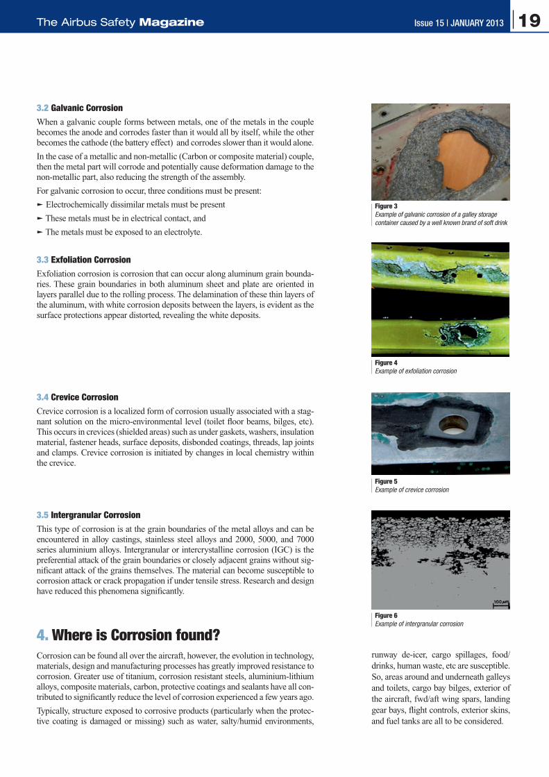
3.2 Galvanic CorrosionWhen a galvanic couple forms between metals, one of the metals in the couple becomes the anode and corrodes faster than it would all by itself, while the other becomes the cathode (the battery effect) and corrodes slower than it would alone.
In the case of a metallic and non-metallic (Carbon or composite material) couple, then the metal part will corrode and potentially cause deformation damage to the non-metallic part, also reducing the strength of the assembly.
For galvanic corrosion to occur, three conditions must be present:
q Electrochemically dissimilar metals must be present
q These metals must be in electrical contact, and
q The metals must be exposed to an electrolyte.
3.3 Exfoliation Corrosion Exfoliation corrosion is corrosion that can occur along aluminum grain bounda-ries. These grain boundaries in both aluminum sheet and plate are oriented in layers parallel due to the rolling process. The delamination of these thin layers of the aluminum, with white corrosion deposits between the layers, is evident as the surface protections appear distorted, revealing the white deposits.
3.4 Crevice CorrosionCrevice corrosion is a localized form of corrosion usually associated with a stag-nant solution on the micro-environmental level (toilet floor beams, bilges, etc). This occurs in crevices (shielded areas) such as under gaskets, washers, insulation material, fastener heads, surface deposits, disbonded coatings, threads, lap joints and clamps. Crevice corrosion is initiated by changes in local chemistry within the crevice.
Figure 4 example of exfoliation corrosion
Figure 5 example of crevice corrosion
Figure 6 example of intergranular corrosion
Figure 3 example of galvanic corrosion of a galley storage container caused by a well known brand of soft drink
3.5 Intergranular CorrosionThis type of corrosion is at the grain boundaries of the metal alloys and can be encountered in alloy castings, stainless steel alloys and 2000, 5000, and 7000 series aluminium alloys. Intergranular or intercrystalline corrosion (IGC) is the preferential attack of the grain boundaries or closely adjacent grains without sig-nificant attack of the grains themselves. The material can become susceptible to corrosion attack or crack propagation if under tensile stress. Research and design have reduced this phenomena significantly.
4. Where is Corrosion found?Corrosion can be found all over the aircraft, however, the evolution in technology, materials, design and manufacturing processes has greatly improved resistance to corrosion. Greater use of titanium, corrosion resistant steels, aluminium-lithium alloys, composite materials, carbon, protective coatings and sealants have all con-tributed to significantly reduce the level of corrosion experienced a few years ago.
Typically, structure exposed to corrosive products (particularly when the protec-tive coating is damaged or missing) such as water, salty/humid environments,
runway de-icer, cargo spillages, food/drinks, human waste, etc are susceptible. So, areas around and underneath galleys and toilets, cargo bay bilges, exterior of the aircraft, fwd/aft wing spars, landing gear bays, flight controls, exterior skins, and fuel tanks are all to be considered.
19Issue 15 | January 2013The Airbus Safety Magazine

5. Possible Consequences of Corrosion
Figure 17 Stress induced corrosion along the fastener holes
Figure 7 Corrosion of a galley foot fitting may lead to the failure of the security of the galley (or toilet) monument and could cause the monument to detach
Figure 8Accumulation of corrosive "products" below a leaking toilet could reduce the thickness of the structure (hence the strength). Aside from the potential health concerns, this may lead to structural failure (decompression)
Figure 9 Corrosion through accumulation of dirt, debris and fluids in the bilge area
Figure 11 Corrosion of electrical bondings, vital for aircraft systems safety (lightening strike, static electricity discharge, etc), could cause them to become ineffective
Figure 10Micro-biological growth in the fuel tanks may lead to bacterial build up in the boundary between the fuel and accumulated water in the tanks. The micro-biological growth could affect the structure and/or block fuel filters/pumps
Figure 12Corrosion between the interlaying surfaces
of aerial connections could lead to loss of communication
Figure 16 Pitting corrosion caused the failure of a landing
gear bogie beam
Figure 18 Cargo bay spillages damaged a cargo floor beam
Figures 13 & 14Missing/damaged protective treatments (Paint,
primer, sealant, plating’s, etc) will all allow ingress of fluids/corrosive products to cause corrosion
damage, hence weakening the structure
Figure 15Water ingress to a landing gear
pin led to pitting corrosion, which attacked the chrome plating and
blocked the lubrication, could lead to the seizure of the landing gear
20 Issue 15 | January 2013 Safety
6. Corrosion Prevention and Control Program (CPCP)Cracks and loss of strength initiated by corrosion and pressurization cycles can lead to major structural failure. After a series of incidents involving old, high flight cycle aircraft, new regulations where introduced by Airworthiness Authori-ties in the early 1990’s requiring manufacturers to develop structural inspections to clearly identify and control corrosion.
To enable operators to do this, Airbus has established a Corrosion Prevention and Control Program (CPCP) for all aircraft maintenance programs. These structural inspections are determined by design analyses, in-service experience and regula-tions. Implementation of these Inspection Programs is mandatory.
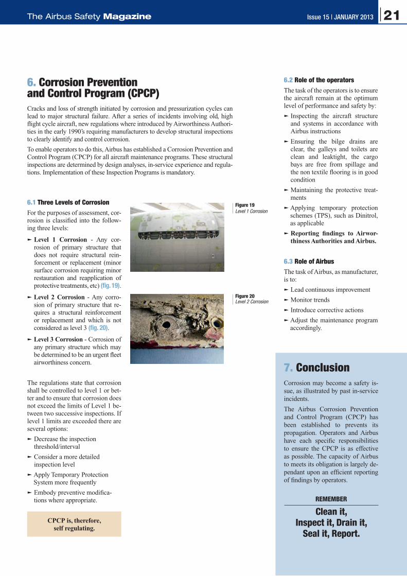
6.1 Three Levels of Corrosion For the purposes of assessment, cor-rosion is classified into the follow-ing three levels:
q Level 1 Corrosion - Any cor-rosion of primary structure that does not require structural rein-forcement or replacement (minor surface corrosion requiring minor restauration and reapplication of protective treatments, etc) (fig. 19).
q Level 2 Corrosion - Any corro-sion of primary structure that re-quires a structural reinforcement or replacement and which is not considered as level 3 (fig. 20).
q Level 3 Corrosion - Corrosion of any primary structure which may be determined to be an urgent fleet airworthiness concern.
The regulations state that corrosion shall be controlled to level 1 or bet-ter and to ensure that corrosion does not exceed the limits of Level 1 be-tween two successive inspections. If level 1 limits are exceeded there are several options:
q Decrease the inspection threshold/interval
q Consider a more detailed inspection level
q Apply Temporary Protection System more frequently
q Embody preventive modifica-tions where appropriate.
CPCP is, therefore, self regulating.
Figure 19 Level 1 Corrosion
Figure 20Level 2 Corrosion
6.2 Role of the operators The task of the operators is to ensure the aircraft remain at the optimum level of performance and safety by:
q Inspecting the aircraft structure and systems in accordance with Airbus instructions
q Ensuring the bilge drains are clear, the galleys and toilets are clean and leaktight, the cargo bays are free from spillage and the non textile flooring is in good condition
q Maintaining the protective treat-ments
q Applying temporary protection schemes (TPS), such as Dinitrol, as applicable
q Reporting findings to Airwor-thiness Authorities and Airbus.
6.3 Role of AirbusThe task of Airbus, as manufacturer, is to:
q Lead continuous improvement
q Monitor trends
q Introduce corrective actions
q Adjust the maintenance program accordingly.
7. Conclusion Corrosion may become a safety is-sue, as illustrated by past in-service incidents.
The Airbus Corrosion Prevention and Control Program (CPCP) has been established to prevents its propagation. Operators and Airbus have each specific responsibilities to ensure the CPCP is as effective as possible. The capacity of Airbus to meets its obligation is largely de-pendant upon an efficient reporting of findings by operators.
REMEMBER
Clean it, Inspect it, Drain it,
Seal it, Report.
21Issue 15 | January 2013The Airbus Safety Magazine

Issue 14, July 2012
– Thrust Reverser Selection Means Full-Stop
– Transient Loss of Communication due to Jammed Push-To-Talk A320 and A330/A340 Families
– A380: Development of the Flight Controls - Part 2
– Preventing Fan Cowl Door Loss
– Do not forget that you are not alone in Maintenance
Issue 13, January 2012
– A320 Family / A330 Prevention and Handling of Dual Bleed Loss
– The Fuel Penalty Factor
– The Airbus TCAS Alert Prevention (TCAP)
– A380: Development of the Flight Controls - Part 1
– Facing the Reality of Everyday Maintenance Operations
Issue 12, July 2011
– Airbus New Operational Landing Distances
– The Go Around Procedure
– The Circling Approach
– VMU Tests on A380
– Automatic Landings in Daily Operation
Issue 11, January 2011
– What is Stall? How a Pilot Should React in Front of a Stall Situation
– Minimum Control Speed Tests on A380
– Radio Altimeter Erroneous Values
– Automatic NAV Engagement at Go Around
Issue 10, August 2010
– A380: Flutter Tests
– Operational Landing Distances: A New Standard for In-flight Landing Distance Assessment
– Go Around Handling
– A320: Landing Gear Downlock
– Situation Awareness and Decision Making
Issue 9, February 2010
– A320 Family: Evolution of Ground Spoiler Logic
– Incorrect Pitch Trim Setting at Takeoff
– Technical Flight Familiarization
– Oxygen Safety
Issue 8, July 2009
– The Runway Overrun Prevention System
– The Take Off Securing Function
– Computer Mixability: An Important Function
– Fuel Spills During Refueling Operations
Issue 7, February 2009
– Airbus AP/FD TCAS Mode: A New Step Towards Safety Improvement
– Braking System Cross Connections
– Upset Recovery Training Aid, Revision 2
– Fuel Pumps Left in OFF Position
– A320: Avoiding Dual Bleed Loss
Articles Published in
22 Issue 15 | January 2013 Safety

The Airbus Safety Magazine
Subscription Form To be sent back to
AIRBUS FLIGHT SAFETY OFFICEFax: 33 (0)5 61 93 44 29Mail to: [email protected]
Name . . . . . . . . . . . . . . . . . . . . . . . . . . . . . . . . . . . . . . . . . . . . . . . . . . . . . . . . . . . . . . . . . . . . . . . . . . . . . . . . . . . . . . . . .
Surname . . . . . . . . . . . . . . . . . . . . . . . . . . . . . . . . . . . . . . . . . . . . . . . . . . . . . . . . . . . . . . . . . . . . . . . . . . . . . . . . . . . . . . .
Job title/Function. . . . . . . . . . . . . . . . . . . . . . . . . . . . . . . . . . . . . . . . . . . . . . . . . . . . . . . . . . . . . . . . . . . . . . . . . . . . . . . . .
Company/Organization. . . . . . . . . . . . . . . . . . . . . . . . . . . . . . . . . . . . . . . . . . . . . . . . . . . . . . . . . . . . . . . . . . . . . . . . . . . . .
Address . . . . . . . . . . . . . . . . . . . . . . . . . . . . . . . . . . . . . . . . . . . . . . . . . . . . . . . . . . . . . . . . . . . . . . . . . . . . . . . . . . . . . . . .
. . . . . . . . . . . . . . . . . . . . . . . . . . . . . . . . . . . . . . . . . . . . . . . . . . . . . . . . . . . . . . . . . . . . . . . . . . . . . . . . . . . . . . . . . . . . . .
. . . . . . . . . . . . . . . . . . . . . . . . . . . . . . . . . . . . . . . . . . . . . . . . . . . . . . . . . . . . . . . . . . . . . . . . . . . . . . . . . . . . . . . . . . . . . .
Post/Zip Code . . . . . . . . . . . . . . . . . . . . . . . . . . . . . . . . . . . . . . . . . . . . . . . . . . . . . . . . . . . . . . . . . . . . . . . . . . . . . . . . . . .
Country . . . . . . . . . . . . . . . . . . . . . . . . . . . . . . . . . . . . . . . . . . . . . . . . . . . . . . . . . . . . . . . . . . . . . . . . . . . . . . . . . . . . . . . .
Telephone . . . . . . . . . . . . . . . . . . . . . . . . . . . . . . . . . . . . . . . . . . . . . . . . . . . . . . . . . . . . . . . . . . . . . . . . . . . . . . . . . . . . . .
Cell phone . . . . . . . . . . . . . . . . . . . . . . . . . . . . . . . . . . . . . . . . . . . . . . . . . . . . . . . . . . . . . . . . . . . . . . . . . . . . . . . . . . . . . .
Fax . . . . . . . . . . . . . . . . . . . . . . . . . . . . . . . . . . . . . . . . . . . . . . . . . . . . . . . . . . . . . . . . . . . . . . . . . . . . . . . . . . . . . . . . . . .
E-mail . . . . . . . . . . . . . . . . . . . . . . . . . . . . . . . . . . . . . . . . . . . . . . . . . . . . . . . . . . . . . . . . . . . . . . . . . . . . . . . . . . . . . . . . . . . . . . . . . . (Mandatory for both digital and paper copies)
Please send me the digital copy* P
Please send me the paper copy* P (Please note that paper copies will only be forwarded to professional addresses)
* Please tick the appropriate case
Safety
Safety FirstThe Airbus Safety Magazine
For the enhancement of safe flight through
increased knowledge and communications
Safety First is published by the Flight Safety Department of Air-bus. It is a source of specialist safe-ty information for the restricted use of flight and ground crew members who fly and maintain Airbus air-craft. It is also distributed to other selected organisations.
Material for publication is obtained from multiple sources and includes selected informa-tion from the Airbus Flight Safety Confidential Reporting System, incident and accident investiga-tion reports, system tests and flight tests. Material is also ob-tained from sources within the airline industry, studies and re-ports from government agencies and other aviation sources.
All articles in Safety First are present-ed for information only and are not intended to replace ICAO guidelines, standards or recommended practices, operator-mandated requirements or technical orders. The contents do not supersede any requirements mand ated by the State of Registry of the Opera-tor’s aircraft or supersede or amend any Airbus type-specific AFM, AMM, FCOM, MEL documentation or any other approved documentation.
Articles may be reprinted without permission, except where copy-right source is indicated, but with acknowledgement to Airbus. Where Airbus is not the author, the con-tents of the article do not necessarily reflect the views of Airbus, neither do they indicate Company policy.
Contributions, comment and feed-back are welcome. For technical reasons the editors may be required to make editorial changes to manu-scripts, however every effort will be made to preserve the intended meaning of the original. Enquiries related to this publication should be addressed to:
AirbusProduct Safety department (GS)1, rond point Maurice Bellonte31707 Blagnac Cedex - FranceContact: Nils FAYAUDE-mail: [email protected]: +33(0)5 61 93 44 29
Safety First, #15 February 2013. Safety First is published by Airbus S.A.S. - 1, rond point Maurice Bellonte - 31707 Blagnac Cedex/France. Editor: Yannick Malinge, Chief Product Safety Officer, Nils Fayaud, Director Product Safety Information. Concept Design by Airbus Multi Media Support Ref. 20130248. Computer Graphic by Quat’coul. Copyright: GS 420.1329 Issue 15. Photos copyright Airbus. Photos by ExM Company, Baldur Sveinsson. Printed in France by Airbus Print Centre.
© Airbus S.A.S. 2013 – All rights reserved. Proprietary documents.
By taking delivery of this Brochure (hereafter “Brochure”), you accept on behalf of your company to
comply with the following guidelines:
3 No other intellectual property rights are granted by the delivery of this Brochure than the right to read
it, for the sole purpose of information.
3 This Brochure and its content shall not be modified and its illustrations and photos shall not be repro-
duced without prior written consent of Airbus.
3 This Brochure and the materials it contains shall not, in whole or in part, be sold, rented, or licensed
to any third party subject to payment.
This Brochure contains sensitive information that is correct at the time of going to press.
This information involves a number of factors that could change over time, effecting the true public
representation. Airbus assumes no obligation to update any information contained in this document or
with respect to the information described herein.
Airbus S.A.S. shall assume no liability for any damage in connection with the use of this Brochure and
of the materials it contains, even if Airbus S.A.S. has been advised of the likelihood of such damages.
A320 Winter operation in Yakutsk, Siberia
Issue 6, July 2008
– A320: Runway Overrun
– FCTL Check after EFCS Reset on Ground
– A320: Possible Consequence of VMO/MMO Exceedance
– A320: Prevention of Tailstrikes
– Low Fuel Situation Awareness
– Rudder Pedal Jam
– Why do Certain AMM Tasks Require Equipment Resets?
– Slide/raft Improvement
– Cabin Attendant Falling through the Avionics Bay Access Panel in Cockpit
Issue 5, December 2007
– New CFIT Event During Non Precision Approach
– A320: Tail Strike at Takeoff?
– Unreliable Speed
– Compliance to Operational Procedures
– The Future Air Navigation System FANS B
Issue 4, June 2007
– Operations Engineering Bulletin Reminder Function
– Avoiding High Speed Rejected Takeoffs Due to EGT Limit Exceedance
– Do you Know your ATC/TCAS Panel?
– Managing Hailstorms
– Introducing the Maintenance Briefing Notes
– A320: Dual hydraulic Loss
– Terrain Awareness and Warning Systems Operations Based on GPS Data
Issue 3, December 2006
– Dual Side Stick Inputs
– Trimmable Horizontal Stabilizer Damage
– Pitot Probes Obstruction on Ground
– A340: Thrust Reverser Unlocked
– Residual Cabin Pressure
– Cabin Operations Briefing Notes
– Hypoxia: An Invisible Enemy
Issue 2, September 2005
– Tailpipe or Engine Fire
– Managing Severe Turbulence
– Airbus Pilot Transition (ATP)
– Runway Excursions at Takeoff
Issue 1, January 2005
– Go Arounds in Addis-Ababa due to VOR Reception Problems
– The Importance of the Pre-flight Flight Control Check
– A320: In-flight Thrust Reverser Deployment
– Airbus Flight Safety Manager Handbook
– Flight Operations Briefing Notes
Previous Safety First Issues
2 Issue 15 | JANUARY 2013 Safety 23Issue 15 | JANUARY 2013The Airbus Safety Magazine

The Airbus Safety Magazine
SafetyEdition January 2013
Issue 15
Subscription Form
SafetyContents:q The Golden Rules for Pilots
Moving from PNF to PM
q Airbus Crosswind Development and Certification
q The SMoke/FuMeS/AvNCS SMoke Procedure
q Post-Maintenance Foreign objects Damage (FoD) Prevention
q Corrosion: A Potential Safety Issue

The Airbus Safety Magazine
Subscription Form To be sent back to
AIRBUS FLIGHT SAFETY OFFICEFax: 33 (0)5 61 93 44 29Mail to: [email protected]
Name . . . . . . . . . . . . . . . . . . . . . . . . . . . . . . . . . . . . . . . . . . . . . . . . . . . . . . . . . . . . . . . . . . . . . . . . . . . . . . . . . . . . . . . . .
Surname . . . . . . . . . . . . . . . . . . . . . . . . . . . . . . . . . . . . . . . . . . . . . . . . . . . . . . . . . . . . . . . . . . . . . . . . . . . . . . . . . . . . . . .
Job title/Function. . . . . . . . . . . . . . . . . . . . . . . . . . . . . . . . . . . . . . . . . . . . . . . . . . . . . . . . . . . . . . . . . . . . . . . . . . . . . . . . .
Company/Organization. . . . . . . . . . . . . . . . . . . . . . . . . . . . . . . . . . . . . . . . . . . . . . . . . . . . . . . . . . . . . . . . . . . . . . . . . . . . .
Address . . . . . . . . . . . . . . . . . . . . . . . . . . . . . . . . . . . . . . . . . . . . . . . . . . . . . . . . . . . . . . . . . . . . . . . . . . . . . . . . . . . . . . . .
. . . . . . . . . . . . . . . . . . . . . . . . . . . . . . . . . . . . . . . . . . . . . . . . . . . . . . . . . . . . . . . . . . . . . . . . . . . . . . . . . . . . . . . . . . . . . .
. . . . . . . . . . . . . . . . . . . . . . . . . . . . . . . . . . . . . . . . . . . . . . . . . . . . . . . . . . . . . . . . . . . . . . . . . . . . . . . . . . . . . . . . . . . . . .
Post/Zip Code . . . . . . . . . . . . . . . . . . . . . . . . . . . . . . . . . . . . . . . . . . . . . . . . . . . . . . . . . . . . . . . . . . . . . . . . . . . . . . . . . . .
Country . . . . . . . . . . . . . . . . . . . . . . . . . . . . . . . . . . . . . . . . . . . . . . . . . . . . . . . . . . . . . . . . . . . . . . . . . . . . . . . . . . . . . . . .
Telephone . . . . . . . . . . . . . . . . . . . . . . . . . . . . . . . . . . . . . . . . . . . . . . . . . . . . . . . . . . . . . . . . . . . . . . . . . . . . . . . . . . . . . .
Cell phone . . . . . . . . . . . . . . . . . . . . . . . . . . . . . . . . . . . . . . . . . . . . . . . . . . . . . . . . . . . . . . . . . . . . . . . . . . . . . . . . . . . . . .
Fax . . . . . . . . . . . . . . . . . . . . . . . . . . . . . . . . . . . . . . . . . . . . . . . . . . . . . . . . . . . . . . . . . . . . . . . . . . . . . . . . . . . . . . . . . . .
E-mail . . . . . . . . . . . . . . . . . . . . . . . . . . . . . . . . . . . . . . . . . . . . . . . . . . . . . . . . . . . . . . . . . . . . . . . . . . . . . . . . . . . . . . . . . . . . . . . . . . (Mandatory for both digital and paper copies)
Please send me the digital copy* P
Please send me the paper copy* P (Please note that paper copies will only be forwarded to professional addresses)
* Please tick the appropriate case
Safety
Safety FirstThe Airbus Safety Magazine
For the enhancement of safe flight through
increased knowledge and communications
Safety First is published by the Flight Safety Department of Air-bus. It is a source of specialist safe-ty information for the restricted use of flight and ground crew members who fly and maintain Airbus air-craft. It is also distributed to other selected organisations.
Material for publication is obtained from multiple sources and includes selected informa-tion from the Airbus Flight Safety Confidential Reporting System, incident and accident investiga-tion reports, system tests and flight tests. Material is also ob-tained from sources within the airline industry, studies and re-ports from government agencies and other aviation sources.
All articles in Safety First are present-ed for information only and are not intended to replace ICAO guidelines, standards or recommended practices, operator-mandated requirements or technical orders. The contents do not supersede any requirements mand ated by the State of Registry of the Opera-tor’s aircraft or supersede or amend any Airbus type-specific AFM, AMM, FCOM, MEL documentation or any other approved documentation.
Articles may be reprinted without permission, except where copy-right source is indicated, but with acknowledgement to Airbus. Where Airbus is not the author, the con-tents of the article do not necessarily reflect the views of Airbus, neither do they indicate Company policy.
Contributions, comment and feed-back are welcome. For technical reasons the editors may be required to make editorial changes to manu-scripts, however every effort will be made to preserve the intended meaning of the original. Enquiries related to this publication should be addressed to:
AirbusProduct Safety department (GS)1, rond point Maurice Bellonte31707 Blagnac Cedex - FranceContact: Nils FAYAuDe-mail: [email protected]: +33(0)5 61 93 44 29
Safety First, #15 January 2013. Safety First is published by Airbus S.A.S. - 1, rond point Maurice Bellonte - 31707 Blagnac Cedex/France. Editor: Yannick Malinge, Chief Product Safety Officer, Nils Fayaud, Director Product Safety Information. Concept Design by Airbus Multi Media Support Ref. 20122260. Computer Graphic by Quat’coul. Copyright: GS 420.1329 Issue 15. Photos copyright Airbus. Photos by ExM Company. Printed in France by Airbus Print Centre.
© Airbus S.A.S. 2013 – All rights reserved. Proprietary documents.
By taking delivery of this Brochure (hereafter “Brochure”), you accept on behalf of your company to
comply with the following guidelines:
3 No other intellectual property rights are granted by the delivery of this Brochure than the right to read
it, for the sole purpose of information.
3 This Brochure and its content shall not be modified and its illustrations and photos shall not be repro-
duced without prior written consent of Airbus.
3 This Brochure and the materials it contains shall not, in whole or in part, be sold, rented, or licensed
to any third party subject to payment.
This Brochure contains sensitive information that is correct at the time of going to press.
This information involves a number of factors that could change over time, effecting the true public
representation. Airbus assumes no obligation to update any information contained in this document or
with respect to the information described herein.
Airbus S.A.S. shall assume no liability for any damage in connection with the use of this Brochure and
of the materials it contains, even if Airbus S.A.S. has been advised of the likelihood of such damages.
A320 Winter operation in Yakutsk, Siberia
Issue 6, July 2008
– A320: Runway Overrun
– FCTL Check after EFCS Reset on Ground
– A320: Possible Consequence of VMO/MMO Exceedance
– A320: Prevention of Tailstrikes
– Low Fuel Situation Awareness
– Rudder Pedal Jam
– Why do Certain AMM Tasks Require Equipment Resets?
– Slide/raft Improvement
– Cabin Attendant Falling through the Avionics Bay Access Panel in Cockpit
Issue 5, December 2007
– New CFIT Event During Non Precision Approach
– A320: Tail Strike at Takeoff?
– U@nreliable Speed
– Compliance to Operational Procedures
– The Future Air Navigation System FANS B
Issue 4, June 2007
– Operations Engineering Bulletin Reminder Function
– Avoiding High Speed Rejected Takeoffs Due to EGT Limit Exceedance
– Do you Know your ATC/TCAS Panel?
– Managing Hailstorms
– Introducing the Maintenance Briefing Notes
– A320: Dual hydraulic Loss
– Terrain Awareness and Warning Systems Operations Based on GPS Data
Issue 3, December 2006
– Dual Side Stick Inputs
– Trimmable Horizontal Stabilizer Damage
– Pitot Probes Obstruction on Ground
– A340: Thrust Reverser Unlocked
– Residual Cabin Pressure
– Cabin Operations Briefing Notes
– Hypoxia: An Invisible Enemy
Issue 2, September 2005
– Tailpipe or Engine Fire
– Managing Severe Turbulence
– Airbus Pilot Transition (ATP)
– Runway Excursions at Takeoff
Issue 1, January 2005
– Go Arounds in Addis-Ababa due to VOR Reception Problems
– The Importance of the Pre-flight Flight Control Check
– A320: In-flight Thrust Reverser Deployment
– Airbus Flight Safety Manager Handbook
– Flight Operations Briefing Notes
Previous Safety First Issues
2 Issue 15 | JANUARY 2013 Safety 23Issue 15 | JANUARY 2013The Airbus Safety Magazine

The Airbus Safety Magazine
SafetyEdition January 2013
Issue 15
Subscription Form
SafetyContents:q The Golden Rules for Pilots
Moving from PNF to PM
q Airbus Crosswind Development and Certification
q The SMoke/FuMeS/AvNCS SMoke Procedure
q Post-Maintenance Foreign objects Damage (FoD) Prevention
q Corrosion: A Potential Safety Issue