safety auditing roundabouts - … · safety auditing roundabouts mark s. lenters, ... 2004 n a t i...
TRANSCRIPT
SAFETY AUDITING ROUNDABOUTS MARK S. LENTERS, P. ENG.,
PREPARED FOR PRESENTATION AT THE 2005
TRANSPORTATION RESEARCH BOARD CONFERENCE ON ROUNDABOUTS
VAIL, COLORADO
SRM Associates
A Member of The Sernas Group Inc. (Sponsors of ROUNDABOUTS CANADA)
110 Scotia Court, Unit 41 Whitby, Ontario L1N 8Y7
roundabouts.ca September, 2004
National R
oundabout Conference 2005 D
RA
FTN
ational Roundabout C
onference 2005 DR
AFT
National R
oundabout Conference 2005 D
RA
FT

a
TABLE OF CONTENTS
PAGE
ABSTRACT....................................................................................................................................................................1 1.0 INTRODUCTION .............................................................................................................................................2 2.0 ROUNDABOUTS – A SOLUTION FOR CANADA’S ROAD SAFETY VISION 2010 .......................................2 3.0 THE ROLE OF FORMAL INTERSECTION SAFETY REVIEWS.....................................................................2 4.0 ROUNDABOUT DESIGN AND OPERATION IS HOLISTIC ............................................................................3 5.0 VISUAL SAFETY AUDIT FINDINGS AND THE NEED FOR FURTHER SAFETY MODELING......................4 6.0 EMPIRICAL CRASH RESEARCH DEFINES ROUNDABOUT AUDITING PRINCIPLES................................4 7.0 BASIC REQUIREMENTS TO ACHIEVING SUCCESS WITH ROUNDABOUT DESIGNS .............................6 8.0 GEOMETRY SAFETY DEFICIENCIES ...........................................................................................................7
8.1 ADEQUACY OF ENTRY PATH DEFLECTION OF ROUNDABOUT APPROACHES ............................7 8.2 ENTRY WIDTH AND DESIGN VEHICLES .............................................................................................9 8.3 EFFECTS OF ENTRY PATH/EXIT PATH OVERLAP ON CRASHES ....................................................8 8.4 RECOGNITION OF CENTRAL ISLAND AND SPLITTER ISLANDS ......................................................9 8.5 HORIZONTAL AND VERTICAL VISIBILITY .........................................................................................10
9.0 PROVISION FOR PEDESTRIANS................................................................................................................11
9.1 RESEARCH INTO THE EFFECTS OF ENTRY PATH CURVATURE ON SPEED AND PEDESTRIAN SAFETY........................................................................................................................12
10.0 SAFETY OF BICYCLISTS.............................................................................................................................13 11.0 SIGNS AND MARKINGS...............................................................................................................................14 12.0 SIGN LAYOUT...............................................................................................................................................14 13.0 ROAD MARKINGS ........................................................................................................................................15 14.0 LIGHTING......................................................................................................................................................16 15.0 TRANSIT .......................................................................................................................................................16 16.0 PAVEMENT AND CROSS-SECTION............................................................................................................16 17.0 PRECONSTRUCTION ON-SITE DESIGN CHECK.......................................................................................17 18.0 SUMMARY ....................................................................................................................................................17 BIBLIOGRAPHY ..........................................................................................................................................................18
National R
oundabout Conference 2005 D
RA
FTN
ational Roundabout C
onference 2005 DR
AFT
National R
oundabout Conference 2005 D
RA
FT

SRM Associates/Roundabouts Canada Safety Auditing Roundabouts Roundabouts Conference May, 2005 1 Vail Colorado .C
ABSTRACT Over the last ten years, roundabouts have spread to North America with good results reported. Except for grade separated interchanges no other type of traffic control exhibits such good safety performance, particularly for high traffic flows at high-speed intersections. Therefore, roundabouts as an engineering initiative can make a significant contribution to a road authority’s safety vision. Intersection safety reviews and safety audits, aimed at improving the physical and operational characteristics of an intersection, are a proven means of facilitating a reduction in crash frequency and crash severity. The process of an in-service safety review requires the assessor to determine what an unfamiliar user would experience as they drive, ride or walk into and out of a roundabout intersection. Although lists of issues affecting safety are identified herein, this document is not a prescription or checklist, but instead points to design principles as the fundamental basis for roundabout safety. Adherence to the principles outlined herein still does not ensure good design; this remains the responsibility of the designer. Although this piece focuses only on safety considerations of roundabout design, the principle that roundabout geometry, signs and markings act holistically must be kept in perspective if roundabouts are to solve both crash prone and highly congested intersections. If not well understood or properly managed, the cumulative effects of poorly managed geometry-safety interactions linked with roundabouts can amount to a significant congestion and/or collision risk. As discussed in this report, the British empirical research into these relationships demonstrates that the separate elements are dependent on the others for their effectiveness. The role of quantifying the potential crash reduction through an examination of the relationship between crashes, traffic flows and geometry represents a significant improvement opportunity in the science of road safety audits of roundabouts not articulated in previous studies. The in-service safety auditor must be aware that even a poorly designed roundabout can operate reasonably well at low traffic flows. A good roundabout design is not proven until the design year flows are experienced because near capacity operations bring out all the design flaws. One hypothesis of this article is that equal consideration should be to both visual and crash model assessment methods in roundabout safety reviews. In particular, there is considerable potential for optimizing safety at the design stage through an understanding of the interactions of geometry and the ability to manipulate these relationships. Through recent study presented herein, knowledge of safety-geometry interactions can be used just as effectively in assessments of in-service roundabouts as in pre-construction design audits. Experience with other types of intersections indicates that there are four basic demands of a safe intersection design. These basic tenets of intersection safety are made practical and gain significance in the safety audit through the range of design elements. Their relationships to the four basic demands on safety can be summarized as follows:
Table 1- Basic Demands of a Safe Intersection Demands of Safe Intersection Design Range of Design Elements
1. Clarity of the situation for approaching drivers Geometric layout; lateral and forward visibility 2. Visibility between road users Lateral and forward visibility
3. Comprehensibility of traffic operations Geometric layout; pedestrians; cyclists; signs and lighting
4. Space for the largest permitted vehicles Geometric layout In this report, the design checks required to attain predicted safety performance and safety enhancements for in-service roundabouts that incorporate the previously established guidelines are presented with examples of design pitfalls and a list of checks to be carried out. This paper provides safety assessment guidelines for all sizes of roundabouts, except mini-roundabouts with fully traversable central islands.
National R
oundabout Conference 2005 D
RA
FTN
ational Roundabout C
onference 2005 DR
AFT
National R
oundabout Conference 2005 D
RA
FT
SRM Associates/Roundabouts Canada Safety Auditing Roundabouts Roundabouts Conference May, 2005 2 Vail Colorado .C
1.0 INTRODUCTION The purposes of this paper are to state the effectiveness of roundabouts in reducing intersection crash frequency and severity, and to provide the basis for understanding the relationships between roundabout safety, geometric design and ancillary design features. This paper is presented with case studies and visual examples of design pitfalls, in order to present principles based guidance for designers. Through discussion and illustrations, an outline of the common problems together with supporting evidence is provided as a basis for good design and safety audits. It is hoped that as more roundabouts are built, a ‘best practice’ for design and safety audits will emerge to uniformly assess safety performance.
The evidence supporting the opinions in this paper are based on an accumulation of public agency research, case studies, area-wide safety audits and the author’s design experience in Canada and the United States.
It is anticipated that the audience for this technical essay are safety auditors and designers who have a cursory understanding of roundabout design and need supplementary advice on safety related problems.
The writer acknowledges the assistance of two mentors who are pioneers in roundabout engineering in North America: Leif Ourston, P.E. of Santa Barbara and Barry Crown of the U.K. Their proven pursuit of empirically based roundabout design and their inspiration to hold science above speculation have greatly influenced the author’s practice. The writer is also grateful to the two recent Ryerson University graduates, Arun Lobo and Mark Jamieson, who volunteered their time to collect speed data to assist in validating the British design practice as applied in a recently constructed roundabout. 2.0 ROUNDABOUTS – A SOLUTION FOR CANADA’S ROAD SAFETY VISION 2010 Modern roundabouts slow down all traffic. Improved safety performance of roundabouts is inherently possible because of the reduced number of user conflicts. A roundabout has less than half the number of conflict points as compared to a stop controlled or signal controlled intersection due to one way circular traffic. Left turn and angle crashes, which produce the most serious injuries at crossroad intersections, are avoided. Lower operating speeds associated with roundabout approaches and circulating traffic in the area of highest conflicts is further basis for improved intersection safety.
Researchers studying crashes and injuries at 24 U.S. intersections before and after construction of roundabouts found a 39 percent overall decrease in crashes and a 76 percent decrease in injury-producing crashes. Collisions involving fatal or incapacitating injuries fell as much as 90 percent.(2) Historically, similar positive results were found in France, Great Britain, Germany and Australia where roundabouts have been in use for over 20 years. Therefore, modern roundabouts as an engineering initiative cannot be ignored for their ability to make a significant contribution to crash reduction at intersections. 3.0 THE ROLE OF FORMAL INTERSECTION SAFETY REVIEWS Intersection safety reviews and safety audits, aimed at improving the physical and operational characteristics of an intersection, are a proven means of facilitating a reduction in crash frequency and crash severity.
Collisions are caused when a failure occurs in the interaction between the road user, the vehicle, and the road environment, and incompatibility between a road’s intended function and the current demands placed upon it can contribute to this failure. Approximately 30 percent of collisions are fully or partially attributed to the road environment. However, many of the collisions that are attributed to road user errors can also be prevented or made less severe by improving the road environment.(3)
National R
oundabout Conference 2005 D
RA
FTN
ational Roundabout C
onference 2005 DR
AFT
National R
oundabout Conference 2005 D
RA
FT

SRM Associates/Roundabouts Canada Safety Auditing Roundabouts Roundabouts Conference May, 2005 3 Vail Colorado .C
Optimizing safety for proposed intersections or improving existing intersections is possible through either safety audits of a re-construction design project or in-service safety reviews. Formal road safety evaluations have been conducted in most jurisdictions on an informal basis. Road safety audits can be applied to a design project and can also be conducted for in-service roads. The major difference is that the in-service safety review evaluates the causes of the exhibited crash characteristics, while the safety audit assesses the crash proneness and predicted safety performance of a design based on knowledge of the relationships and interactions between the geometric elements, the roadside environment and the various users. What makes the audit effective at the design stage is that it is made explicit, as are other aspects of the design such as environmental audits and cost-benefit assessments.
In a safety audit, collision potential is considered at each stage of the design scheme. A formal audit will have four stages:
1. Feasibility/initial design; 2. Preliminary design; 3. Detailed design; and, 4. Construction and pre-opening.
The greatest opportunity to minimize crash proneness through good design is possible at the earliest design stages knowing that the basic geometry influences safety more than any other feature of the roundabout. The reviewer must also be mindful that the review is not just based on checking individual design element conformity, but on considering how the scheme as a whole may affect overall safety, and being able to decide what to do when principles conflict. 4.0 ROUNDABOUT DESIGN AND OPERATION IS HOLISTIC Achieving a balanced design where capacity, safety and minimal cost are optimized is what makes roundabout design complex. Modern roundabout design practice requires a heuristic principle-based approach that recognizes the holistic nature of the way roundabouts should be designed to achieve safe and efficient operations. Understanding the trade-offs of setting priorities among competing objectives of cost, safety and capacity in design is necessary to achieve an optimal balanced design.
For example, it is not difficult to design for a single variable such as safety alone as some European jurisdictions have proved with design practice that has been called ‘continental’; however, exploring the whole design space is necessary to achieve optimal results for intersections with both high speed and high traffic flows. In a traffic circular regarding cyclists and continental design geometry, as published by the U.K. Department for Transport, research into the collateral effects of tight entry and exit radii (continental design), while appearing to improve cyclist safety, result in reduced roundabout capacity for the majority of users, passenger car drivers.(4)
Although this piece focuses only on safety considerations of roundabout design, these prevailing principles must be kept in perspective if roundabouts are to solve both crash prone and highly congested intersections. If not well understood or properly managed, the cumulative effects of poorly managed geometry-safety interactions linked with roundabouts can amount to a significant collision risk. The British empirical research into these relationships demonstrates that the separate elements are dependent on the others for their effectiveness.
The in-service safety reviewer must be aware that even a poorly designed roundabout can operate reasonably well at low traffic flows. A good design is not proven to be so until the design year flows are experienced. Near capacity operations bring out all the design flaws. The influence of traffic signs, intersection lighting and pavement markings on safety performance is not easily quantified, but human factors knowledge and design heuristics facilitates a qualitative assessment of driver task load.
National R
oundabout Conference 2005 D
RA
FTN
ational Roundabout C
onference 2005 DR
AFT
National R
oundabout Conference 2005 D
RA
FT

SRM Associates/Roundabouts Canada Safety Auditing Roundabouts Roundabouts Conference May, 2005 4 Vail Colorado .C
This naturally leads to an assessment of the cumulative effects of positive guidance and navigation features on driver expectancy, a major consideration in roundabout engineering as well as conventional intersection design. Hence the safety performance of all the components of a roundabout intersection can be assessed holistically.
Finally, a prime objective of the safety review is to balance the needs of all users by assessing and comparing the levels of risk. Although it should go without saying, the safety review must also consider financial and design constraints. 5.0 VISUAL SAFETY AUDIT FINDINGS AND THE NEED FOR FURTHER SAFETY
MODELING Following a review of 50 safety audit reports of New Zealand roundabouts, a publication was commissioned to identify the most common problems with roundabouts.(5)
PROBLEM PERCENTAGE Signs 15% New Markings 9% Cyclists 7% Inadequate Deflection 7% Delineation 6% Lane Configuration 6% Pedestrians 6% Visibility 6% Sight Lines 6% Pole Location 5% Lighting 5%
The most common problems with roundabouts were identified by safety auditors as relating to the location, appropriateness, size and quantity of signs. There is a consensus that poor signage can lead to a variety of road safety problems, including poor driver guidance, high approach speeds and poor driver recognition of intersection control. Insufficient or incorrect pavement markings were also cited as a source of driver confusion.
Other key issues raised by the auditors included lack of proper consideration for cyclists and inadequate deflection as motorists approach the intersection. The writer appreciates permission to reproduce the Transfund New Zealand report findings as provided by Ian Appleton, Safety Audit Manager. Apart from the excellent effort put forward by the auditors, they did not report on safety concerns related to geometric design deficiencies with the exception of entry deflection. It is possible, but improbable, that there were few inherent geometric deficiencies to report on. The audit reports appear to have followed visual assessment methods of in-service safety reviews, applying positive guidance techniques without further quantitative investigation of crash performance based on geometry-crash relationships as identified by the British empirical research of Maycock and Hall.(6) The role of quantifying the potential crash reduction through an examination of the relationship between crashes, traffic flows and geometry represents a significant improvement opportunity in the science of road safety audits of roundabouts. 6.0 EMPIRICAL CRASH RESEARCH DEFINES ROUNDABOUT AUDITING
PRINCIPLES People, not cars, drive roundabouts. The UK empirical approach to capacity and accident prediction is based upon observations of at capacity, in-service, operations. Rather than try to mathematically explain one characteristic of
National R
oundabout Conference 2005 D
RA
FTN
ational Roundabout C
onference 2005 DR
AFT
National R
oundabout Conference 2005 D
RA
FT

SRM Associates/Roundabouts Canada Safety Auditing Roundabouts Roundabouts Conference May, 2005 5 Vail Colorado .C
roundabout operations, empirical research encompasses the range of driving behavior and operational mechanisms. This method has proved remarkably successful in Great Britain and is showing early signs of similar success on high volume crash prone intersections in the United States. Links have been established between geometry and injury accidents.(6) Equations have been developed to enable prediction of roundabout crashes for appraisal of existing roundabouts and for use in design. The costly research undertaken in the early 1980’s using four years of data has identified relationships between safety and geometry for a wide range of traffic flows and geometric conditions.
Since it is extremely unlikely that a change, which reduces crashes in the UK, is going to have the reverse effect in North America, the relationships are expected to prove dependable for predicting the major effects of design changes. With the exception of the prediction model for pedestrians, which is a function of entering and exiting traffic flows, the four main accident types dependant on entering flow, circulating flow and roundabout geometry are:
1. Entry/circulating crashes - a vehicle entering the roundabout collides with a circulating vehicle.
2. Approach crashes involving two or more vehicles
approaching the junction. These are sideswipes and rear-end crashes.
3. Single vehicle accidents involving a single
vehicle on an approach colliding with the street furniture or simply leaving the roadway.
4. Other Accidents. This includes motorcyclists or a
variety of other relatively infrequent accidents.
5. Pedestrian related crashes for which no geometric parameters were attributed are a function of the entering and exiting traffic flows.
The most noteworthy features of the empirically researched accident prediction model have been illustrated from the extensive data collected on a four-year sample of 84 four-arm roundabouts in the U.K. as shown on Figure 1.(6) Barry Crown demonstrated the primary crash related geometric features in his paper to the International Symposium “Giratoires 92” in Nantes, France.(7) His extensive experience including recent safety audit work in North America has confirmed what was found in the earlier research, namely that changes in one geometric element reduce the probability of one collision type, but can increase the chances of another. The net effect may increase or decrease accidents as a function of the volume of entering versus circulating traffic. Mr. Crown echoed the importance of empirically derived relationships between several key geometric variables, traffic flows and collision potential previously established through extensive observations as follows:
The Angle Between Arms (θ): Increasing the angle sharply reduces accident frequency. Equally spaced arms are therefore safest. Consequently designs with a reduced number of equally spaced arms may be safer. However this needs to be checked as it may increase the circulating and entry flows on the remaining arms leading to a net increase in accidents.
Figure 1- Definition of Geometric Parameters in the Predictive Relationship (Source: 6 )
Ce = 1/Re E
CID
ICD
National R
oundabout Conference 2005 D
RA
FTN
ational Roundabout C
onference 2005 DR
AFT
National R
oundabout Conference 2005 D
RA
FT

SRM Associates/Roundabouts Canada Safety Auditing Roundabouts Roundabouts Conference May, 2005 6 Vail Colorado .C
The Entry Width (E) - small increases in the Entry Width produce significant increases in accident frequency. Applying entry flaring in combination with moderate entry path curvature can produce both improved capacity and balanced safety performance.
The Approach Curvature (Ca not shown on Figure 1) — This is the reciprocal of the approach radius
and is measured between 165 feet (50 metres) and 1650feet (500 metres) on the approach to the junction. Extreme changes in the Approach Curvature produces quite small changes in accident frequency.
The Circulating Width — Accident frequency increases with small increases in Circulating Width.
The Entry Path Radius (Ce) - This is the minimum radius taken by a straight-ahead vehicle entering the
junction along the fastest possible path. It is measured within 165feet (50 metres) of the junction. Accident frequency varies significantly with Entry Path Radius. Very small values must be avoided. Usually values are large and need to be reduced. The optimum value will depend on the specific entry and circulating flows.
The Half Width (v) - Increasing the Half Width over its whole range produces only a very small reduction
in accidents. In a safety auditor’s report on roundabouts in the County of Warwickshire in the U.K., the investigators cited entry angle as a source of safety problems.(8) The work by Hall and Maycock(6) indicated entry angle, the estimated conflict angle between entering and circulating streams of traffic, was quite effective in statistical terms, but not easy to define or use in a design sense. Thus entry path curvature was chosen to represent deflection based on its usability as a design parameter. Nevertheless, too high an entry angle can prove deceptive to drivers by not providing sufficient guidance to judge the severity of the radius on entering the roundabout. Consequently, high entry angles can contribute to single vehicle loss of control with drivers traveling too fast for the entry radius. Very low entry angles, conversely, can lead to entry-circulating and rear end crashes as demonstrated in the crash histories of old rotaries designed for merging and weaving of entering and circulating traffic.
The UK empirical approach to accident prediction has proved successful for the whole range of roundabout sizes from mini-roundabouts up to three and four lane entries in native instances. In North America there are too few roundabouts covering the range of design and traffic flows suitable for development of a safety model; however, the British research can be used reliably in relative terms because it is unlikely that a change, which reduces crashes in the UK, is going to have the reverse effect in North America. 7.0 BASIC REQUIREMENTS TO ACHIEVING SUCCESS WITH ROUNDABOUT
DESIGNS Experience with other types of intersections indicates that there are four basic demands of a safe intersection design. These basic tenets of intersection safety are made practical and gain significance in the safety audit through the range of design elements. Their relationships to the four basic demands on safety can be summarized as shown on Table 1.
Table 1- Basic Demands of a Safe Intersection Demands of Safe Intersection Design Range of Design Elements
1. Clarity of the situation for approaching drivers Geometric layout; lateral and forward visibility 2. Visibility between road users Lateral and forward visibility
3. Comprehensibility of traffic operations Geometric layout; pedestrian accommodations; cyclists; signs and lighting
4. Space for the largest permitted vehicles Geometric layout
National R
oundabout Conference 2005 D
RA
FTN
ational Roundabout C
onference 2005 DR
AFT
National R
oundabout Conference 2005 D
RA
FT

SRM Associates/Roundabouts Canada Safety Auditing Roundabouts Roundabouts Conference May, 2005 7 Vail Colorado .C
In the following sections, the fundamental design checks required to attain predicted safety performance and safety enhancements for in-service roundabouts that incorporate historically proven guidelines are presented with examples of design pitfalls and a list of checks to be carried out. This paper provides safety assessment guidelines for all sizes of roundabouts except mini-roundabouts with fully traversable central islands. 8.0 GEOMETRY SAFETY DEFICIENCIES Whether considering an in-service roundabout or a scheme yet to be built, changes to geometric layout provide the greatest opportunity to optimize safety. The following is a summary list of investigations the safety practitioner must undertake when assessing the geometry of a roundabout:
Are deflection angles of the approach roads adequate? Is the centre island prominent? Are deflection (splitter) islands prominent and do they ensure adequate vehicle speed reduction through
deflection? Is the roundabout of adequate size for all vehicular movements? Are dedicated lanes necessary? Are the central island, yield line, markings and signs meeting visibility criteria for conspicuity? Is parking allowed near the roundabout?
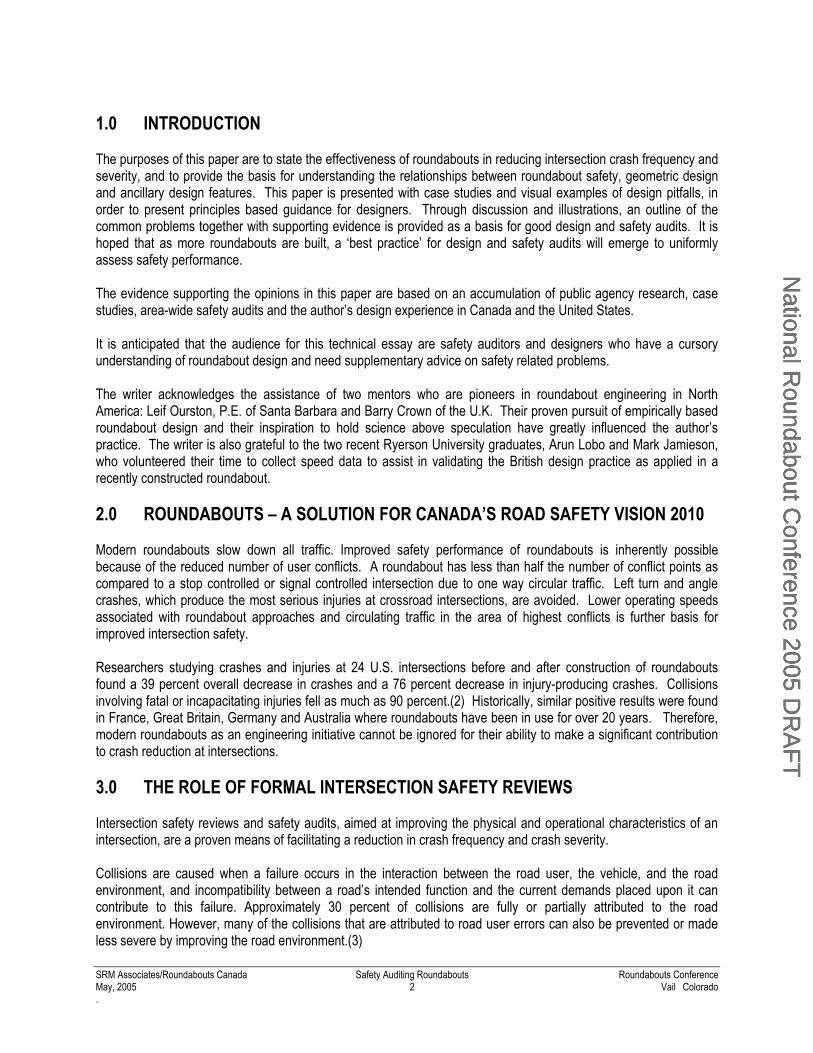
8.1 ADEQUACY OF ENTRY PATH DEFLECTION OF ROUNDABOUT APPROACHES For safety, it is crucial to design in sufficient deflection on the approach. The idea is to slow vehicles down before they reach the give way line, not as they reach it, or even after they have entered. If the entry is overtly tangential, then vehicles tend to arrive at the conflict point too fast, leading to unnecessary crashes between entering and circulating vehicles. Conversely, if the entry path curvature is too tight as with perpendicular or sharply curved entries, then there is a rise in single vehicle crashes resulting from loss of control on the approach to the roundabout. Entry path radius should be less than 230feet (70 metres) for best results in single lane roundabouts and less than 330feet (100 metres) for multi-lane design. Based on the earlier referenced empirical data, when flaring roundabout entries, safety impacts of wider entries can be mitigated with entry path curve values down to 100feet (30 metres). When considering the effects of entry path curvature, it should be recognized that approach related single vehicle type of crashes associated with perpendicular or sharply deflected entries tend to be higher speed and result in more severe injuries. Thus continental design with nearly perpendicular entries is undesirable at high-speed rural intersections where it is important to reduce speed with approach and entry geometry that gives the driver sufficient guidance as to appropriate entry speed in addition to the obvious visual clue of a central island barrier. Entry path curvature is vital to establishing natural paths for multi-lane roundabout entries to prevent overlap of parallel streams of traffic upon entry. The illustrations below depict examples of too much deflection (Figure 2) and insufficient deflection (Figure 3).
National R
oundabout Conference 2005 D
RA
FTN
ational Roundabout C
onference 2005 DR
AFT
National R
oundabout Conference 2005 D
RA
FT
SRM Associates/Roundabouts Canada Safety Auditing Roundabouts Roundabouts Conference May, 2005 8 Vail Colorado .C
Figure 2 - An Over-deflected Entry Figure 3 - Insufficient Entry Path Curvature (This layout also suffers from entry path overlap)
The conditions shown in Figure 2 control speed of entry, but are prone to approach type crashes such as rear end and single vehicle crashes if entering traffic flow is high. This condition can lead to overlap of the paths of two entering vehicles upstream of the entry. Figure 3 depicts a condition that is prone to entry circulating crashes and overlap of the paths of two entering vehicles in the roundabout. Tight entry radii coupled with insufficient entry path curvature produces a combination of crash results.
With wide entries, necessary for high capacities, selection of a central island large enough to ensure that drivers cannot take a straight line across the roundabout is vital; however, the designer cannot rely on central island size alone as entry radius and entry angle are also crucial to avoiding paths that overlap or are too fast, particularly for multi-lane roundabouts.
Entry path curvature must be applied with consideration of the combination of traffic flows on the leg in question and the circulating flows. A high entry flow with low circulating flow can benefit from less entry path curvature (EPC). The key to effectively assessing the safety performance related to entry path curvature is to review the traffic flows and assess the magnitude of conflicts that are created by increasing or decreasing EPC. 8.2 EFFECTS OF ENTRY PATH/EXIT PATH OVERLAP ON CRASHES On multilane roundabouts, the entry and exit streams must not overlap their paths in order to prevent sideswipe crashes. Path overlap occurs where either stream of traffic crosses the path of the other (see Figure 3). Achieving the combination of slowed entry paths, no entry path overlap and accommodating the design vehicle all compete. Experienced designers have shown that it is possible to achieve a balance between all three elements with optimal safety and capacity because the practitioner understands and manipulates the relationship of traffic flows to the design mechanism specific to the entry or exit in question. It is not sufficient to address the principle of natural entry and exit paths apart from the requisite traffic flows because the trade-offs that may be necessary depend on the traffic flow demands of that design. Another form of exit path overlap is attributed to incorrect lane use. Lane designation signs and exit striping are recommended for most multi-lane roundabouts, but again lane designation depends upon lane utilization, which in turn is a function of traffic flows. The designer must be cautious in using lane designation markings and signs since this treatment is usually applied in conjunction with more complex spiral markings.
National R
oundabout Conference 2005 D
RA
FTN
ational Roundabout C
onference 2005 DR
AFT
National R
oundabout Conference 2005 D
RA
FT

SRM Associates/Roundabouts Canada Safety Auditing Roundabouts Roundabouts Conference May, 2005 9 Vail Colorado .C
8.3 ENTRY WIDTH AND DESIGN VEHICLES Entry width is a dominant factor in both the capacity and safety of a roundabout. Wide entry widths expose pedestrians to traffic for longer periods and it is therefore desirable to have narrower entry widths in urban areas. Widening of entries, particularly without additional entry path curvature, leads to an increase in accidents, which is more pronounced for multi-lane roundabouts. The U.K. capacity prediction model uses entry width rather than number of lanes to increase capacity, allowing the designer to add capacity without needing to consider a whole lane increment. Thus promotion of safer design is partly built into the British practice. Narrow lanes cause problems for large vehicles, especially in combination with tight radii as in continental design practice.
Figure 4 - WB-19 Swept Path (130feet (40m) ICD, 18feet (5.5m) Entry/Exit)
As a given design year for roundabouts is often set 20 years ahead to allow for future demands, entries wider than necessary for the early years of operation are unavoidable for initial traffic conditions. Wider entries, for example 15feet to 18feet (4.5 to 5.5m) (see Figure 4), are required for typical heavy trucks and snow ploughs. Since design vehicle requirements are unavoidable, it is usually necessary to pavement mark/hatch out some of the entry width with road markings to narrow the entries for passenger cars. 8.4 RECOGNITION OF CENTRAL ISLAND AND SPLITTER ISLANDS The consequences of an inconspicuous central island and/or splitter islands is mainly loss of control crashes as motorists unfamiliar with the roundabout are not given sufficient visual information to elicit a change in speed and path. The two figures below contrast poor design of the central island and improved design using planting but still missing signs. Maintaining the largest splitter island possible and using vertical curb face is necessary to aid in deflecting traffic on the approach to a roundabout entry as well as providing an adequate refuge for pedestrians. Coupled with the need for a physical interruption of driver sight through the intersection is the need to reinforce the presence of raised curbs in the centre of the roadway using chevrons and lighting.
National R
oundabout Conference 2005 D
RA
FTN
ational Roundabout C
onference 2005 DR
AFT
National R
oundabout Conference 2005 D
RA
FT

SRM Associates/Roundabouts Canada Safety Auditing Roundabouts Roundabouts Conference May, 2005 10 Vail Colorado .C
Figure 5 - An Obscure Central Island Figure 6 - A More Conspicuous Central Island Correct design of the splitter islands ensures good deflection and speed adjustment into the roundabout entry. This is particularly important for multi-lane roundabout operation where natural parallel paths for two or more vehicles entering the roundabout are essential to prevent path overlap. Good ‘body language’ for a roundabout includes splitter island design that discourages left turns against the circulatory flow. The adjacent figure illustrates a corrected splitter island layout reinforced with continuity markings. Attempting to correct a poorly designed splitter island with pavement markings alone will not suffice.
Figure 7 - An Entry Modified to Improve Natural Paths
8.5 HORIZONTAL AND VERTICAL VISIBILITY Drivers must be able to see the yield line together with the centre and splitter islands, in order for them to judge the layout of the roundabout with sufficient time to perceive, react and brake safely. Therefore stopping sight distance related to the operating speed of the approach roads and the circulatory governs vertical sight of the roundabout. If a vertical crest hides a yield line, drivers may not brake in time and will overshoot the entry. In some cases, additional warning signs may be helpful, but these should not be relied upon to completely negate the accident risk of low stopping sight distance.
The design of approach lanes must be such that visibility is sufficient to allow approaching vehicles, cyclists or pedestrians to be clearly seen and in adequate time for appropriate decisions to be made. The safe and efficient movement of traffic generally relies on good unobstructed lines of sight. However, providing visibility to the right beyond 15 metres back from the yield line can encourage drivers to compete for gaps at the roundabout entry. Conversely insufficient sight to the left near the entry can result in entry-circulating crashes. Signs, vegetation and street furniture should not interfere with sight for approaching and circulating traffic.
Both the FHWA Guide and Ourston’s guide (See Figure 8) prescribe horizontal and vertical sight guidelines that are based on approach speeds and circulating traffic speeds. In the Ourston guide, sight to the left is limited to the vehicle at the entry whereas the FHWA guide assumes that the vehicle to the left is 15m behind the yield line. Similarly, clear-view areas to the right require sight of the pedestrian crosswalk across the corner day-lighting which allows the driver making a right turn to view a pedestrian that may enter the crosswalk as a driver makes a right turn.
Visibility To The Left At Entry All Other Visibility
Figure 8 - Vertical Sight Distance Requirements after Ourston(10)
National R
oundabout Conference 2005 D
RA
FTN
ational Roundabout C
onference 2005 DR
AFT
National R
oundabout Conference 2005 D
RA
FT

SRM Associates/Roundabouts Canada Safety Auditing Roundabouts Roundabouts Conference May, 2005 11 Vail Colorado .C
9.0 PROVISION FOR PEDESTRIANS Roundabouts are perceived by some to be less safe for pedestrians; but, compared to traffic signal crosswalks they provide an accurate reading of risk. Crossing of approaches or exits to roundabouts is a simpler process for the pedestrian because the vehicle approaches from one direction and generally in the full view of the pedestrian. Design and marking of crosswalks requires awareness of the potential for unmatched expectancies of pedestrians and drivers. Facilities must be provided as close as possible to the desired pedestrian paths to ensure their effectiveness, and their treatment in terms of visibility and design requires knowledge of the frequency of crossings. The British design guidelines, now translated to North American driving by Ourston(10), prescribe a method of warrants for various levels of pedestrian accommodation ranging from no splitter island refuge to a split traffic signal crosswalk. The variables are vehicular traffic flow and flow of pedestrians, weighting vehicular traffic flow by an exponential proportion to recognize the disproportion. The designer should not simply place markings or assume the need for a higher level of pedestrian accommodation apart from knowledge of the frequency of crossings. Crossing location is fundamental to pedestrian safety, recognizing the driver’s need to look left at the roundabout entry and the need to separate conflict areas. Placing the crosswalk one vehicle length removed from the yield line ensures this separation, but does not create unreasonably long walking distances for the whole intersection. Figure 9 shows a cross walk placed too close to the point of entry, which results in vehicles covering the cross walk. Clear, safe guidance of pedestrians in the crossing area requires clear linkage to the crosswalk, visibility of the refuge area, but not a clear, uninterrupted path from one side of the road to the other (Figure 11). In such cases, bicyclists are tempted to cross without stopping at the refuge area.
Figure 9 - Poorly Located Cross Walk The two figures below show contrasting treatments where the crossing alignment affects the perception of the right-of-way. The angularity of the crossing shown on Figure 10 also minimizes the crossing distance and provides a tactile clue of the refuge.
Figure 10 - Angled Cross Walk with Detectable Treatments Figure 11 - Cross Walk Alignment That Is Too Enticing
National R
oundabout Conference 2005 D
RA
FTN
ational Roundabout C
onference 2005 DR
AFT
National R
oundabout Conference 2005 D
RA
FT

SRM Associates/Roundabouts Canada Safety Auditing Roundabouts Roundabouts Conference May, 2005 12 Vail Colorado .C
Visibility between drivers and pedestrians is prescribed by Ourston(10) and reiterated in the FHWA guidelines.(11) Sight of the first exit crosswalk from the driver’s position, 50feet (15m) upstream of the yield line is mandatory. Plantings and fencing or street furniture must not interfere with this safety provision.
The use of guiderails and fencing to restrict pedestrian crossing areas is commonly used in the U.K. at intersections with high pedestrian volumes. In our North American climate with snow clearing requirements, fencing is impractical unless farther removed from the edge of pavement. Plantings are preferred and perform the same purpose, while providing improved aesthetics. Whether plantings or fencing is used, heights must be restricted to below 3.5feet (1.05m) above the pavement surface. In either case, the need should be established where the risk to pedestrians is high.
Finally, the use of pedestrian crossing warning signs on the approach to a roundabout entry, as indicated in the FHWA guide, is not recommended by the author since these additional signs convey a message to the driver that he/she should expect to yield to pedestrians upon arriving at the crosswalk. Unless the jurisdiction in question has a highway code that provides for pedestrian right-of-way, a mismatch of expectations can result. The appropriate method of crossing treatment ensures that drivers are aware of pedestrians nearby, but that pedestrians do not assume that they have the right-of-way until a driver yields it. 9.1 RESEARCH INTO THE EFFECTS OF ENTRY PATH CURVATURE ON SPEED
AND PEDESTRIAN SAFETY In 2003, Bill Baranowski and Edmund Waddell authored a watershed thesis entitled: “Alternate Design Methods For Pedestrian Safety At Roundabout Entries And Exits”.(12) This paper came about as the result of the authors observing roundabout designers who, in an attempt to slow exiting traffic to protect pedestrians, have constructed roundabouts with excessively tight entry and exit radii. This practice has resulted in roundabouts with unnecessarily low capacity and high vehicle crash rates in some cases. Their paper made a case for the design of high capacity roundabouts that are safe for pedestrians while optimizing flow efficiency for vehicular traffic.
Two separate studies of pedestrian crash incidence indicated the majority of pedestrian-vehicle crashes occur at roundabout entries versus exits(13, 14). These results indirectly point out the need to control entry speed and that by doing so, entry speed will take care of exit speed.
The author of this paper researched the speed curvature relationships for a modern roundabout built at the intersection of Wilson Street (former Highway 2) and Meadowbrook Road, Ancaster, Ontario in 2002. At the author’s request, two Ryerson University students gathered spot speed data on six occasions for two-hour periods each, collecting a total of twelve hours of speed data. Figure 12 shows the conceptual roundabout configuration and the locations of speed data collection. The hypothesis regarding the effects of entry speed on exit speed was the same as Baranowski and Waddell, that the exit radius does not control the exit speed as much as it is controlled by the entry path curvature. The speed data results (see Table 2) provided by Lobo and Jamieson, the two Ryerson graduates, indicate the differential in entry and exit speeds is low, averaging only 4mph (6 km/h) for the 85th percentile speed on the high-speed 50mph (80 km/h) approach, Wilson Road West. The radius on the exit side of the Wilson Street East leg is flatter than some would prefer; suggesting the exit speed, calculated according to radius friction factors should be higher than observed. Because the speed reduction occurring at the entry is sustained through the circulating roadway according to the central island radii, and because the distance from the central island to the exit is too short for excessive acceleration, the exit speed cannot increase as one might expect.
This finding is significant for North American roundabouts because it validates British practice of high capacity roundabouts as being capable of limiting entry and exit speed to the benefit of pedestrians and cyclists.
National R
oundabout Conference 2005 D
RA
FTN
ational Roundabout C
onference 2005 DR
AFT
National R
oundabout Conference 2005 D
RA
FT

SRM Associates/Roundabouts Canada Safety Auditing Roundabouts Roundabouts Conference May, 2005 13 Vail Colorado .C
Figure 12 - Spot Speed Observation Points (Lobo and Jamieson, 2003)
(Note: the as-built roundabout does not have patterned contrasting crosswalk treatments)
Table 2 – Overall Results of Spot Speed Observations [mph(km/h)] Wilson West Meadowbrook Road Wilson West Spot Speed
Statistic Entering Exiting Entering Exiting Entering Exiting Circulating
Mode 16.1(26) 23.6(38) 18.6(30) 22.9(37) 21.7(35) 26.7(43) 17.3(28) Average 16.1(26) 21.7(35) 18.6(30) 22.3(36) 20.5(33) 24.8(40) 17.3(28) Standard Deviation 3.3(5.4) 3.1(5.2) 3.8(6.2) 3.0(4.9) 5.5(8.8) 3.5(5.7) 3.0(4.9)
85th Percentile 19.2(31) 25.4(41) 22.3(36) 25.4(41) 24.2(39) 27.9(45) 20.5(33) Maximum 25.4(41) 29.8(48) 27.9(45) 33.5(54) 28.5(46) 31(55) 27.3(44) Minimum 7.4(12) 10.5(17) 6.8(11) 14.2(23) 7.4(12) 13.6(22) 7.4(12)
10.0 SAFETY OF BICYCLISTS The majority of bicycle related collisions at roundabouts are entry/circulating, with the entering car hitting the circulating bicycle. Very good entry path deflection will slow down entering traffic and minimize bicycle crashes. On small roundabouts, the circulating traffic is much closer to the yield line and the entering driver’s focus is much closer and the bicycle is much more within the driver’s depth of vision and is more easily seen. Unfortunately, on larger roundabouts (ICD’s larger than 200feet (60m)) the circulating traffic is faster and the entering driver focuses on circulating vehicles some distance away and looks past the bicycle about to pass in front of the yield line. Fewer entry lanes are preferred as the bicycle is at risk passing each one on the circulating roadway. Narrow entries and compensating long flare lengths are better for bicycles approaching an entry, particularly because as the bicyclist approaches the roundabout it must take the lane as would a vehicle.
Therefore, designs with increased deflection and small inscribed circles and slower circulating traffic can be expected to be safer for bicycles. This is widely consistent with crash studies. Thus, compact design with small inscribed circles, robust entry deflection, minimal entry width (and circulating width), all controlling vehicle speed, make roundabouts more bicycle friendly.
The FHWA prescribes the use of combined pedestrian/bicycle crossings, with connecting bicycle lanes on the sidewalk to provide a safe route for bicycles separate from the circulating road. Dropping the bicycle lane and directing bicycles onto the sidewalk away from the circulating road is expected to improve cyclist safety; however,
National R
oundabout Conference 2005 D
RA
FTN
ational Roundabout C
onference 2005 DR
AFT
National R
oundabout Conference 2005 D
RA
FT
SRM Associates/Roundabouts Canada Safety Auditing Roundabouts Roundabouts Conference May, 2005 14 Vail Colorado .C
most avid cyclists would prefer to remain on the roadway becoming, a vehicle by highway code definition, once they take up a lane at the roundabout entry.
The key in assessing the safety risks of bicyclists is to know the bicycle volumes. A good design that provides high capacity should be ideal for all users where the overall risks are balanced. Only where bicycle traffic is noticeable would the balance of priorities shift and a roundabout pose a higher risk for overall safety reasons. Continental design with tighter entries can help cyclists, however overall capacity can be considerably reduced as a result. Therefore, context sensitivity is essential to assessing the risk and need to explore the balance between the needs of all users. 11.0 SIGNS AND MARKINGS Inadequate provision and/or poorly located signs and markings contribute to guidance and navigational errors in the driving task. Normally these types of driving task errors do not result in crashes, but in the case of roundabouts, a poor lane choice may result in drivers reaching a point in the circulatory roadway where a sudden lane change is the only way to correct for the preferred exit. Exit crashes can be avoided with proper lane designation and map type advance signs in conjunction with lane markings.
Traffic signs and road markings should be an integral part of the design process for roundabouts since lane designation may be associated with entry flaring, exit design and splitter layout. The questions that should be asked by a designer or peer reviewer are:
Is the signing adequate and easily understood? Is there consistency among signs and markings to provide clarity of approach? Are the appropriate warning signs provided at the correct distance form the hazard? Can the signs be seen over the visibility distance or does landscaping or other signs obscure
visibility? Are the signs appropriate for the design speed? Do the markings clearly define routes and priorities in conjunction with lane designation? Do the markings and letter heights of signs meet standards of visibility and conspicuity?
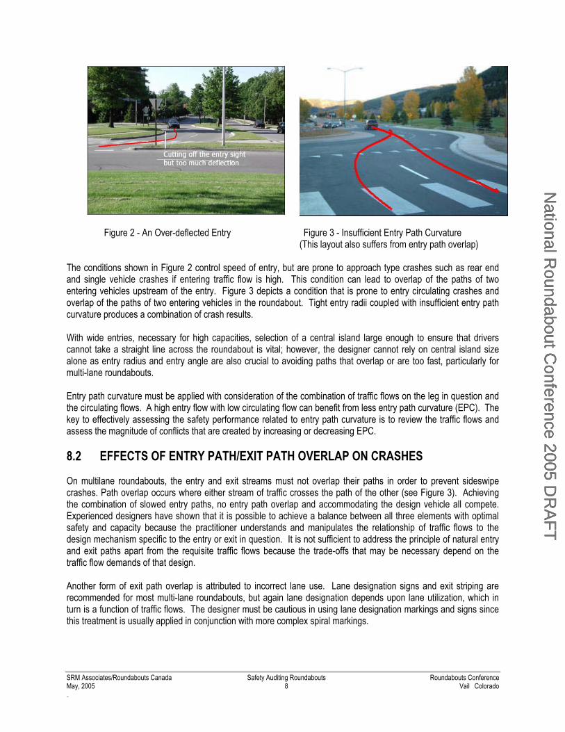
12.0 SIGN LAYOUT The U.K. Traffic Signs Manual(15) describes the signposting for roundabouts that is recommended for use with only minor changes to reflect North American roadway classification and driving. A universal standard signposting for roundabouts should consist of the following in addition to the standard pair of yield signs on each approach:
Advance direction sign (ADS). Used in rural areas, and in urban areas where
possible, this is a map type sign on each approach arm. If stack signs are used in urban areas, there should also be a “roundabout ahead” sign. The provision of good advance signage allows motorists to plan their route in advance of the roundabout, adjust their speed, and select the appropriate lane from which to enter the roundabout.
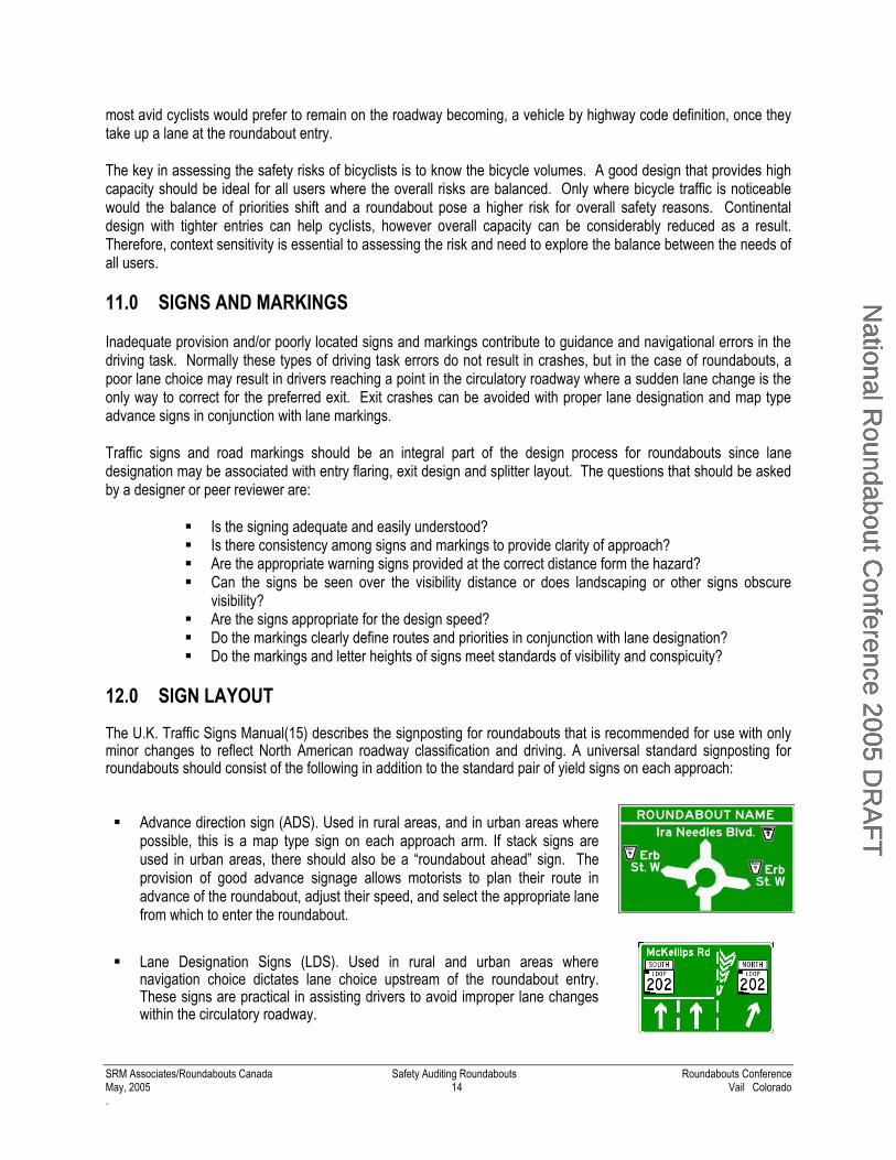
Lane Designation Signs (LDS). Used in rural and urban areas where navigation choice dictates lane choice upstream of the roundabout entry. These signs are practical in assisting drivers to avoid improper lane changes within the circulatory roadway.
National R
oundabout Conference 2005 D
RA
FTN
ational Roundabout C
onference 2005 DR
AFT
National R
oundabout Conference 2005 D
RA
FT

SRM Associates/Roundabouts Canada Safety Auditing Roundabouts Roundabouts Conference May, 2005 15 Vail Colorado .C
Flag type direction sign (DS). Placed at each exit, usually on the deflection
island, as per route information shown on the ADS.
Keep-right illuminated bollards or an RB-25 sign with a WA-33 chevron. These are required to meet regulatory standards and are supplementary to the map type ADS.
A roundabout ahead warning sign with “reduce speed now” plate, used on
high standard roads in addition to the ADS, and sited on both sides of the approach roadway. In North America, the appropriate sign background colour would be black or white instead of red.
White and black chevron arrows on the central island sited opposite the entries to a roundabout, whose size depends on the speed of the road. Currently, a one-way arrow board, implying regulatory requirements, is also being used until such time as it becomes apparent that the one-way sign is redundant.
(Rural example)
Since the United Kingdom has the most extensive experience in roundabouts, and the most comprehensive roundabout signage, in laying out the map-type direction, flag-type exit and lane assignment signs, the U.K. signing manual(15, 16) is the preferred reference until North American standards for roundabout information signing emerge.
The map-type direction signs should be located a minimum distance upstream of the roundabout yield lines in accordance with British Practice (16). The lane assignment signs, in conjunction with lane arrows, located between the map-type signs and the yield lines, are essential for lane conscious North Americans who are as yet not accustomed to multi-lane roundabouts. The recommended configurations are consistent with U.K. practices, and conforms to the use of intersection lane control signs as described in the 2003 Manual of Uniform Traffic Control Devices (MUTCD). 13.0 ROAD MARKINGS Single lane roundabout striping is quite simple and is generally used to outline the splitter islands and to place the yield line. If a truck apron is to be used, there should not be a yellow annular stripe around the edge of the truck apron. Shadowing lines against the splitter islands on large entries and exits is useful to show drivers that only one lane of traffic is allowed, even though the curb to curb width is wide to accommodate large trucks.
The use of yellow bar markings on the approaches to roundabouts is one option for giving drivers advance warning of the junction ahead, if the approach is high speed. These markings may be particularly suitable on rural roundabout approaches where background visual stimuli are lacking but it should only be applied to divided roadways
Figure 13 - Bar Markings for Rural Conditions
National R
oundabout Conference 2005 D
RA
FTN
ational Roundabout C
onference 2005 DR
AFT
National R
oundabout Conference 2005 D
RA
FT

SRM Associates/Roundabouts Canada Safety Auditing Roundabouts Roundabouts Conference May, 2005 16 Vail Colorado .C
Multi-lane roundabout striping is considerably more complex. Concentric circulating roadway stripes should not be used to avoid exit crash problems.(17) The choice of markings depends upon the traffic flows on each individual lane into and out of each leg of the roundabout and whether short lane flaring is in use. Careful judgment is needed to ensure that the capacity is not adversely affected by a poor choice of lane marking assumptions. Therefore, there are no standard lane markings for multi-lane roundabouts apart from a consideration of queuing and lane utilization. 14.0 LIGHTING Illumination of the roundabout intersection should be given considerable attention, as positive contrast lighting and vertical luminance is essential for pedestrian and signage visibility. Poor or inappropriate lighting of a roundabout can lead to motorists entering the intersection with inadequate information, which can lead to driver confusion, emergency braking and/or loss of control night-time accidents, in addition to delays due to poorly illuminated guidance features.
Proper illumination will ensure that all physical elements including splitter islands are clearly lit. The guidelines currently being developed indicate peripheral lighting is preferred over widespread central flood lighting as the former gives improved positive contrast to important visual elements.(18). Pole placements should respect clear zone requirements for a safer roadside as dictated by design speed. The pole placement should give clues to the driver that the through roadway sight at night is interrupted by the change in lighting patterns at the intersection. Figure 14 - Approach Mounted Lighting 8-250W HPS
(Courtesy: DMD Associates Electrical Consultants) 15.0 TRANSIT At traffic signals, the preferred location of bus stops is generally ‘far side’. Stops can be located on either side of a roundabout, but there are advantages to locating it after the roundabout if a lay-by lane is provided. If a bus is likely to block the entry or exit lane, a far side stop is not preferred as blocking the exit may affect more than one approach. If buses are very frequent, then they should be taken into account in the design. 16.0 PAVEMENT AND CROSS-SECTION The central island of a roundabout can be made more prominent by setting the slope of the circulating roadway to drain outwards to the outside diameter. This works especially well in single lane roundabouts, but in multi-lane roundabouts the inner lane should slope inward to aid vehicles on the shorter radius relative to cars on the outside of the circle and trucks tracking the inner radius. British experience has established this practice to balance speeds and to avoid a large pavement surface draining all in one direction. Ourston’s Roundabout Design Guidelines provides a typical cross-section for a rolled crown on a multi-lane roundabout as shown in Figure 15.(10) The effect of lowering the central island is duly compensated for by the placement of regulatory one-way chevrons and conspicuous island plantings.
Figure 15 - Setting the Crossfall For Multi-Lane Roundabouts (10)
National R
oundabout Conference 2005 D
RA
FTN
ational Roundabout C
onference 2005 DR
AFT
National R
oundabout Conference 2005 D
RA
FT

SRM Associates/Roundabouts Canada Safety Auditing Roundabouts Roundabouts Conference May, 2005 17 Vail Colorado .C
A roundabout profile should not be sloped on a grade greater than 4% to avoid tipping trucks. Similarly, truck aprons should not be sloped greater than 2% to prevent truck overturning. The mountable curb height should be approximately 100mm to discourage use of the apron by SUV’s, but not higher so as to affect truck stability. Pavement surface roughness should be maximized for near entry braking and to develop maximum roadway friction in the circulatory roadway. Heavy-duty pavement, e.g. HL1 or DFC, is recommended to minimize rutting and lateral pavement deflection. For in-service conditions, U.K. road authorities have found that one of the most effective crash countermeasures has been to install anti-skid surfacing. One product consists of a thin coat of crushed shells in an epoxy base.
Figure 16 - Shell-coat Skid Treatment 17.0 PRECONSTRUCTION, ON-SITE, DESIGN CHECK While the experienced designer can overcome most of the design challenges with due diligence, even the most skillfully designed roundabout can come undone through the construction process. Therefore, a check of the completed scheme at the stage on construction just prior to placement of curbs provides the essential check of the survey layout points. The designer should visit the construction site with a tape measure to verify entries, exits, circulatory roadway width and the angle of splitter islands at the yield line. An unchecked error in the layout of the splitter island on a multi-lane roundabout can translate to an entry path overlap problem.
Similarly, the designer should attend to the pre-marking work to verify the layout of exit markings and more complicated spiral markings prior to their final application. In some cases, if the designer is not confident of the expected traffic flows, use of temporary or non-durable markings will provide the desired evaluation period at minimal risk. Errors in the placement of these important guidance elements can contribute to unwelcome conflicts.
18.0 SUMMARY The traffic engineer needs design methods that will enable him to get directly from his proposed geometry to realistic estimates of safety and confidence that the design method will give sound, dependable results, even with an unusual layout. There are a several basic requirements to achieving safe design with roundabout designs that have been highlighted in this publication. The Safety Auditor needing to assess the relative benefits of alternatives or combinations of countermeasures should account for benefits in relation to costs. Although not discussed in this paper, The Transportation Association of Canada provides references to guide the economic evaluation step by step using techniques such as net present value.(3) It can be said of design practice that the only thing more difficult than learning by experience is not learning from experience. Some of the identified problems highlighted by safety audits can easily be modified during the design process; however, if a poor design is left unchanged, the necessary alterations to rectify the roundabout design could be costly. If a design is in service and showing signs of crash proneness, it is either due to inexperience on the part of the designer, changes in the operating parameters not anticipated in the original design or lack of peer review. Roundabout designs can benefit from being peer reviewed or audited whether formally or informally to ensure the intended outcomes.
National R
oundabout Conference 2005 D
RA
FTN
ational Roundabout C
onference 2005 DR
AFT
National R
oundabout Conference 2005 D
RA
FT

SRM Associates/Roundabouts Canada Safety Auditing Roundabouts Roundabouts Conference May, 2005 18 Vail Colorado .C
BIBLIOGRAPHY 1. Transport Canada and the Canadian Council of Motor Transport Administrators, (CCMTA), Road Safety Vision
2010, Transport Canada, 2000. 2. Retting, R.A.; Persaud, B.N.; Garder, P.E. and Lord, D. 2001 Crash Reductions Following Installation of
Roundabouts in the United States. American Journal of Public Health 91/4:6128-631 3. The Transportation Association of Canada, The Canadian Guide to In-Service Road Safety Reviews, 2003. 4. TRL Report 285: Cyclists At Roundabouts - The Effect of Continental Design on Predicted Safety and Capacity
and TAL 09/97: Cyclists at Roundabouts: Continental Design Geometry. 5. Traffic Design Group for Transfund New Zealand, The Ins and Outs of Roundabouts - Safety Auditors’
Perspective, 2002. 6. Maycock, G. and Hall, R D., Accidents at 4 Arm Roundabouts. TRRL LR1120, TRRL 1984. 7. Crown, R.B., RODEL An Interactive Model for Predicting the Effect of Detailed Roundabout Geometry on
Accidents, Capacity, Queues and Delays, Highways Department, Staffordshire County Council, England, “Giratoires 92”, Nantes, France.
8. West Midlands Region Road Safety Audit Forum, A Safety Auditor’s View of Roundabout Design, An Update,
Warwickshire County Council, England, April 1997. 9. Standards for Road Safety Audits (DMRB, HD 19/94) and Advice Note for Road Safety Audits (DMRB, HA
42/94), UK Department for Transport. 10. Ourston, L., P.E., Roundabout Design Guidelines, 2000. 11. Roundabouts: An Informational Guide, June 2000, FHWA. 12. Bill Baranowski, P.E. RoundaboutsUSA, and Edmund Waddell, Michigan DOT, Alternate Design Methods for
Pedestrian Safety at Roundabout Entries and Exits: Crash Studies and Design Practices in Australia, France, Great Britain and the USA, 2003.
13. Jordan, P.W.: Pedestrians and Cyclists at Roundabouts, Third National Local Government Engineering
Conference, Institution of Engineers, Melbourne, AU, August 1985. 14. Tumber, C: Review of Pedestrian Safety at Roundabouts, Vic Roads, Road Safety Department Melbourne , AU,
April 1997. 15. The Design of Traffic Signs, Chapter 7, Traffic Signs Manual, U.K. Department for Transport, 2003. 16. The Design and Use of Directional Informatory Signs, Appendix A, Local Transport Note 1/94, U.K. Department
for Transport, July 1994, (see also Ch.6 and DOT, DMRB 8.2 (264)). 17. Design of Road Markings at Roundabouts TA 78/97, UK Department for Transport. 18. Lighting guidelines being developed by DMD Associates, Electrical Consultants, Vancouver, B.C.
National R
oundabout Conference 2005 D
RA
FTN
ational Roundabout C
onference 2005 DR
AFT
National R
oundabout Conference 2005 D
RA
FT