safeguarding and protective measures. legislation, theory...
TRANSCRIPT

Safeguarding and Protective Measures.Legislation, Theory and Practice.

INTRODUCTION
The purpose of this book is to provide discussion, assistance and guidance foranyone concerned with the safety of machinery, especially protective systems,guarding and interlocking. It is intended to be useful for both designers andusers of industrial equipment.
In recent years there have been significant changes within Europe tolegislation with regard to both the design and use of machinery. In order topromote the concept of an open market within the EC and EFTA all membercountries are obliged to enact legislation which lays down common essentialsafety requirements for machinery and its use. Machinery which does notmeet these requirements cannot be sold into or within EC andEFTA countries.
It is important to understand that this legislation is intended to create a levelplaying field based on common safety requirements which encouragescompetition and innovation without compromising safety standards. Users anddesigners of machinery who adopt a positive and pro-active approach willbenefit from a universal and cohesive safety conformity system within Europe.The first step in taking advantage of the situation is to understand the basicstructure of the legislation and associated standards.
1

THE EJA ENGINEERING GROUP
The EJA Engineering group manufactures equipment for the safe operationand control of machinery and processes.
The Group comprises Guardmaster Ltd, Nelsa Ltd, and Sigma Controls Ltd. Italso has subsidiary sales companies in France, Germany and the USA. Inaddition to this, a global distributor network ensures that EJA products andadvice are available worldwide.
Guardmaster LtdGuardmaster produces one of the World’s most comprehensive range ofinterlock switches, emergency stop devices and monitoring equipment.Products include:
Mechanical and non-contact interlock switches.Conditional and non-conditional guard locking switches.Grabwire and push button emergency stop switches.Monitoring safety relay units.Stopped motion detection systems.Timer units.
For more information and a comprehensive catalogue contact Guardmaster.Telephone 01942 255166 Fax 01942 523259.
Nelsa LtdNelsa manufactures guarding systems for machines and production processes.Their products range from “off the shelf” bolt on guards for commonly usedmachines to sophisticated electronic protective systems which can beintegrated with machine control systems to provide full monitored point ofoperation, area and perimeter safeguarding.Products include:
Safety light curtains.Pressure sensitive footmats.Pressure sensitive edges and bumpers.Emergency braking systems.Physical guards and shields.Special purpose guards and systems.
For more information and a comprehensive catalogue contact Nelsa.Telephone 01942 257111 Fax 01942 257177.
86

RISK ASSESSMENT• Determine the machine's operating characteristics and limits.
• Identify the hazards. • Estimate the risk.See: Chapter 4 Safety Strategy.
THE MACHINERY DIRECTIVENew machinery supplied within the EC
must satisfy the Essential Health and Safety Requirements.
See: Chapter 1 Directives & Legislation. Chapter 2 Harmonised European Standards.
THE USE OF WORK EQUIPMENT DIRECTIVE
Employers must ensure that all work equipment provided is suitable and safe.
See: Chapter 1 Directives & Legislation. Chapter 2 Harmonised European Standards.
RISK REDUCTION• Take any measures required to elliminate the hazards or reduce the risk to an
acceptable level.See: Chapter 3 Choice of Protective Measures. Chapter 5 Safety Related Control Systems.
Chapter 6 Further Considerations and Examples. Chapter 7 Interlocking Devices.
TECHNICAL FILE• Ensure the availability of information required to check the conformity of the
machine. See: Chapter 1 Directives & Legislation.
APPROVED BODIES• Where necessary (Annex IV
machines) take appropriate action with an Approved Body.
See: Chapter 1 Directives & Legislation.
DECLARATION• Prepare a Declaration of Conformity
or a Declaration of Incorporation.• Where appropriate affix the CE mark.
See: Chapter 1 Directives & Legislation.
• Employers must ensure that work equipment is safe, maintained in
efficient working order and in good repair.
• Employers must ensure that suitable instruction and training is available together with adequate health and
safety information.
Manufacturers and employers may need to satisfy other EC Directives in addition to those discussed in this book.Affixation of the CE mark is intended to indicate compliance with all relevant EC Directives.
A FAST TRACK GUIDE TO CONTENTS IN RELATION TO MACHINERY SAFETY LEGISLATION
3

USEFUL QUESTIONS FOR THE SELECTION OF INTERLOCK DEVICESThe following questions will assist in the logical selection of the most suitabletype of interlocking device.
Does the machine take time to run down after power isolation?YES = Guard locking with timed delay may be required.
Is the machine stopping time predictable and constant?NO = Conditional guard locking with motion sensing may be required.
Is whole body access required?YES = Key operated guard locking with personnel key may be required.
Can a crash stop cause machine or control system damage?YES = Conditional guard locking may be required.
Will there be guard wear causing misalignment at the interlockdevice?
YES = A non-contact device may be required.
Does the device need to be totally sealed e.g. for hygienecleansing or high humidity environment?
YES = A non-contact device may be required.
Is frequent access required?YES = Control interlocking may be most suitable.
Is it likely that there will be attempts to cheat the interlockdevice?
YES = A device with increased security may be required.
84

There are several other European Directives, either in place or beingprepared, with relevance to industrial safety. Most of them are fairlyspecialised in their application and are therefore left outside the scope of thisbook but it is important to note that, where relevant, their requirements mustbe met. Examples are - The Low Voltage Directive - The EMC Directive - The Prevention of explosion due to hazardous atmospheres Directive.
THE MACHINERY DIRECTIVE 89/392/EEC as amended by 91/368/EECand 93/44/EEC (enacted in UK law as The Supply of Machinery (Safety)Regulations 1992).
Fig. 1This Directive covers the supply of new machinery and other equipmentincluding safety components. In most cases it is an offence to supplymachinery unless it complies with the Directive. This means that it must satisfywide ranging essential safety requirements contained in Annex I of theDirective, a correct conformity assessment must be carried out and a“Declaration of Conformity” must be given.
The Directive came into full force for machinery on 1st January 1995 and forSafety Components on 1st January 1997. Up to these dates a preceding twoyear transition period was allowed whereby either existing nationalregulations could be used or the new Directive regime could be followed.It is the responsibility of the manufacturer, importer or end supplier of theequipment to ensure that equipment supplied is in conformity with theDirective.
5
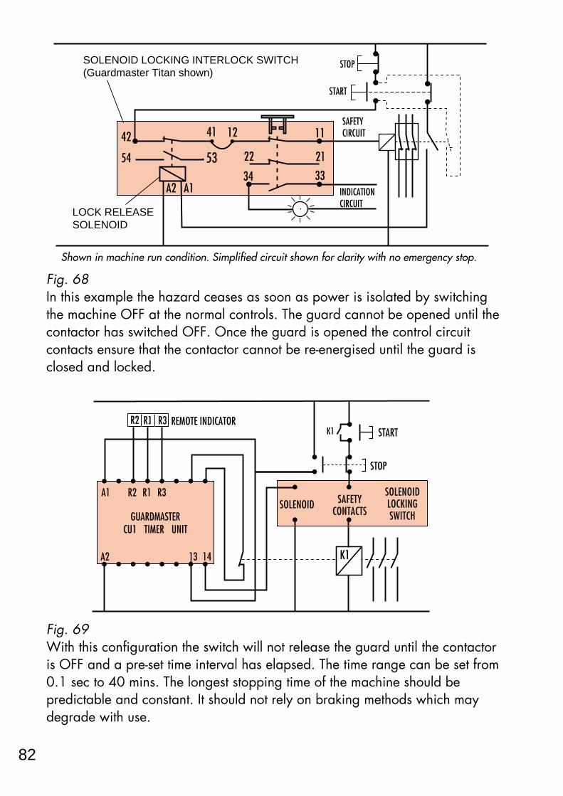
Fig. 68In this example the hazard ceases as soon as power is isolated by switchingthe machine OFF at the normal controls. The guard cannot be opened until thecontactor has switched OFF. Once the guard is opened the control circuitcontacts ensure that the contactor cannot be re-energised until the guard isclosed and locked.
Fig. 69With this configuration the switch will not release the guard until the contactoris OFF and a pre-set time interval has elapsed. The time range can be set from0.1 sec to 40 mins. The longest stopping time of the machine should bepredictable and constant. It should not rely on braking methods which maydegrade with use.
A2 13 14
A1 R2 R1 R3
REMOTE INDICATOR
GUARDMASTERCU1 TIMER UNIT
START
STOP
K1
K1
SOLENOID SAFETYCONTACTS
SOLENOIDLOCKINGSWITCH
R1R2 R3
Shown in machine run condition. Simplified circuit shown for clarity with no emergency stop.
A1A2
42
54
11
21
33
22
3453
41 12
INDICATION CIRCUIT
SAFETY CIRCUIT
START
STOPSOLENOID LOCKING INTERLOCK SWITCH(Guardmaster Titan shown)
LOCK RELEASESOLENOID
82

Guards or protection devices must be used to protect risks such as movingparts. These must be of robust construction and not be easy to by-pass. Fixedguards must be held in place by fixings which can only be undone with tools.Movable guards should be interlocked. Adjustable guards should be readilyadjustable without the use of tools.
Electrical and other energy supply hazards must be prevented. There must beno risk of injury from temperature, explosion, noise, vibration, dust , gasses orradiation. There must be proper provision for maintenance and servicing.Sufficient indication and warning devices must be provided. Machinery shallbe provided with instructions for safe installation, use, adjustment etc.
There are special requirements for agri-foodstuffs, hand-held, wood workingmachines and also lifting and underground equipment.
CONFORMITY ASSESSMENT
Fig. 3The designer or other responsible body must be able to show evidence in theform of a technical file that proves conformity with the EHSRs. This file shouldinclude all relevant information such as test results, drawings, specificationsetc. as shown below.
Where equipment is designed to specified harmonised European standards itsimplifies the task of showing conformity. These standards are not legallycompulsory, however, their use is strongly recommended as provingconformity by alternative methods can be an extremely complex issue.Chapter 2 explains the structure of these standards which are produced byCEN (the European Committee For Standardisation) and CENELEC (theEuropean Committee For Electrotechnical Standardisation) to support theMachinery Directive. Together CEN and CENELEC form the Joint Institute ForStandardisation In Europe.
TEST RESULTS------------------------------------------------------------
STANDARDS
7

Fig. 66On a device such as the Guardmaster CENTURION time delay bolt switch atime delay is imposed. The bolt which locks the guard in place also operatesthe contacts. The bolt is withdrawn by turning the operating knob. The firstfew turns open the contacts but the locking bolt is not fully retracted until theknob is turned many more times (taking up to 20 secs.).The Sigma PROSAFE trapped key system (see power interlocking section) canalso be used to provide unconditional guard locking.Features:These devices are simple to fit and they are extremely rugged and reliable.The time delay bolt switch is suitable mainly for sliding guards.
For consideration:The stopping time of the hazard being guarded must be predictable and itmust not be possible for the bolt to be withdrawn before the hazard hasceased. It must only be possible to extend the bolt into its locked positionwhen the guard is fully closed. This means that it will usually be necessary tofit stops to restrict the travel of the guard door.
Conditional Guard UnlockingWith these devices the guard can only be opened on receipt of a signalshowing that:
- the contactor is OFF.- a pre-set time interval has elapsed or alternatively that dangerous motionhas ceased.
These signals are usually derived from the auxiliary contacts of the contactor
80
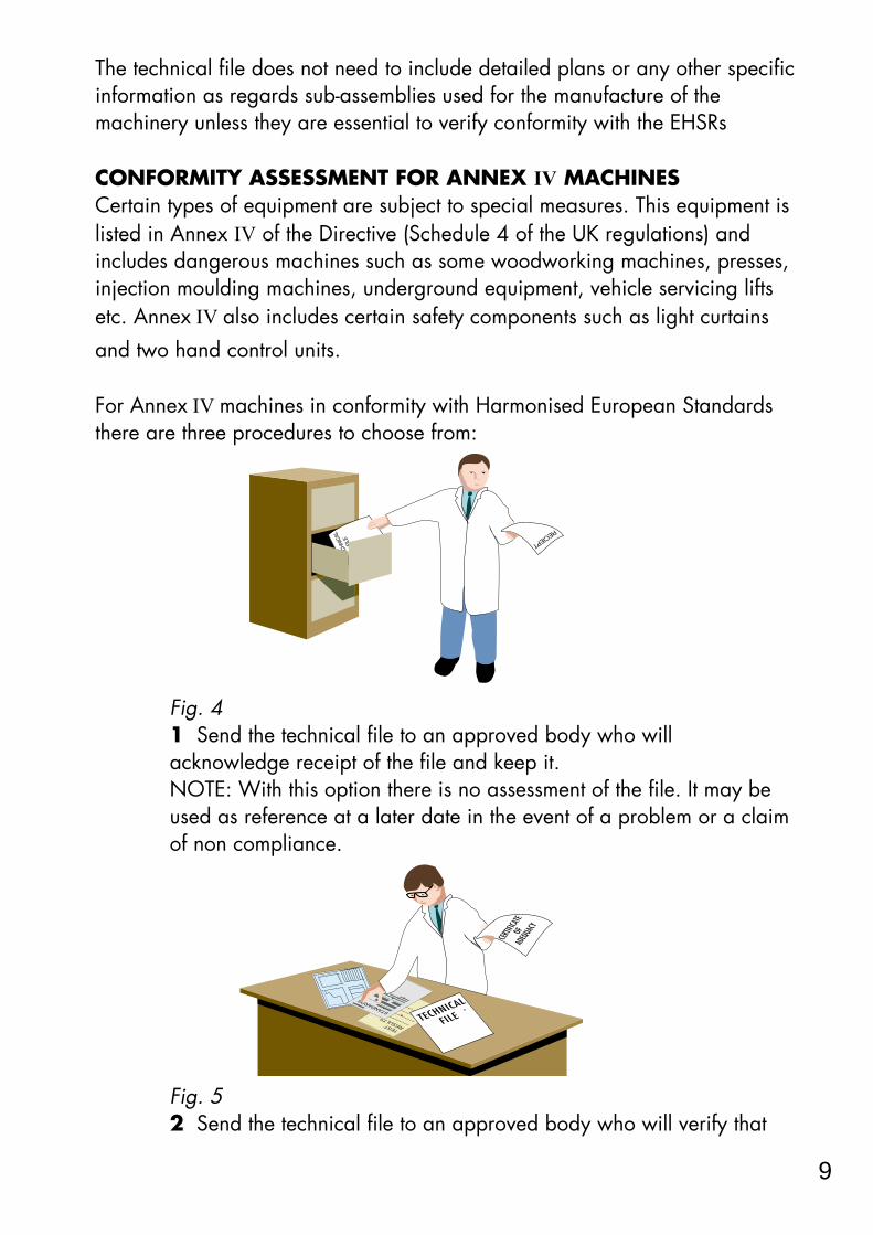
The technical file does not need to include detailed plans or any other specificinformation as regards sub-assemblies used for the manufacture of themachinery unless they are essential to verify conformity with the EHSRs
CONFORMITY ASSESSMENT FOR ANNEX IV MACHINESCertain types of equipment are subject to special measures. This equipment islisted in Annex IV of the Directive (Schedule 4 of the UK regulations) andincludes dangerous machines such as some woodworking machines, presses,injection moulding machines, underground equipment, vehicle servicing liftsetc. Annex IV also includes certain safety components such as light curtainsand two hand control units.
For Annex IV machines in conformity with Harmonised European Standardsthere are three procedures to choose from:
Fig. 41 Send the technical file to an approved body who willacknowledge receipt of the file and keep it.NOTE: With this option there is no assessment of the file. It may beused as reference at a later date in the event of a problem or a claimof non compliance.
Fig. 52 Send the technical file to an approved body who will verify that
TEST RESULTS-----
--------
----------
------
----------
----------
----------
-
STANDARDS
TECHNICAL
FILE
9
device and the reed contacts. Because it is non resettable the switch should beprotected by a suitably rated external fuse.
It is important that the switch is only operated by its intended actuator. Thismeans that ordinary proximity devices which sense ferrous metal for exampleare not appropriate. The switch should be operated by an “active” actuator.
The security can be further improved by coding such as on the GuardmasterFerrotek. This switch uses the same oriented failure mode principle as theFerrogard but has higher security due to its coded actuator and sensor.
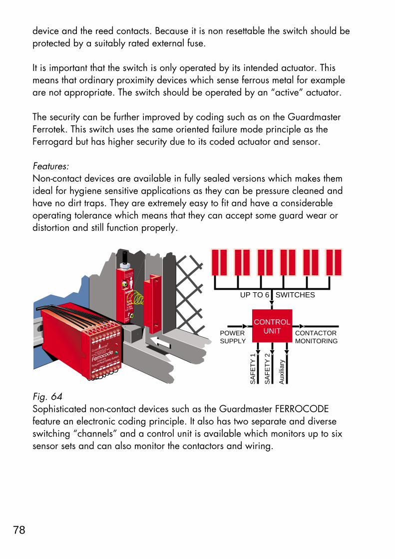
Features:Non-contact devices are available in fully sealed versions which makes themideal for hygiene sensitive applications as they can be pressure cleaned andhave no dirt traps. They are extremely easy to fit and have a considerableoperating tolerance which means that they can accept some guard wear ordistortion and still function properly.
Fig. 64Sophisticated non-contact devices such as the Guardmaster FERROCODEfeature an electronic coding principle. It also has two separate and diverseswitching “channels” and a control unit is available which monitors up to sixsensor sets and can also monitor the contactors and wiring.
Wigan WN2 4HR
0942 55166
Safety
Switch1A 28Vdc
0.5A 120Vac
Made in
England
IP 67
Ferrocode
R
Tamper Proof Safety System
Guardmaster Ltd.
Wigan, England.WN2 4HR
Tel: 0942 55166
Control UnitFerrocode
Aux Safety 1 S
afety 2 Grn Yel
X1 X2 Red Blue Blk Wht
SA
FE
TY
1
SA
FE
TY
2
Aux
iliar
y
UP TO 6 SWITCHES
CONTACTORMONITORING
POWER SUPPLY
CONTROLUNIT
78

EHSRs applicable to it. If the examination is successful an EC typeexamination certificate will be issued. A body which refuses to issue acertificate must inform the other approved bodies.
DECLARATION OF CONFORMITY PROCEDUREThe responsible person must draw up an EC DECLARATION OFCONFORMITY and affix the CE mark to all machines supplied. The machinesshould also be supplied with the Declaration of Conformity. NOTE: Safety components should have a Declaration of Conformity but not aCE mark in respect of the Machinery Directive (although they may be CEmarked with respect of the EMC or Low Voltage Directives).
Fig. 7The CE mark represents self certification but it is an offence to affix the CEmark unless the machine satisfies the EHSRs and it is in fact safe. It is also anoffence to affix a mark to machinery which may be confused with the CEmark.NOTE: The affixing of the CE mark also indicates compliance with any otherEuropean directives to which the machinery may be subject.
11

For consideration:Care must be taken on large wide guard doors as an opening movementof only 3° can still result in a significant gap at the opening edge on verywide guard doors. It is also important to ensure that a heavy guard doesnot put undue strain on the switch actuator shaft.
Cam Operated Actuation
Fig. 61This type of arrangement usually takes the form of a positive mode actinglimit (or position) switch and a linear or rotary cam. It is usually used onsliding guards and when the guard is opened the cam forces the plungerdown to open the control circuit contacts.
Features:The simplicity of the system enables the switch to be both small andreliable.
For consideration:It cannot be used on lift-off guards.It is extremely important that the switch plunger can only extend when theguard is fully closed. This means that it may be necessary to fit stops tolimit the guard movement in both directions.It is necessary to fabricate a suitably profiled cam which must operatewithin defined tolerances. The guard mounted cam must never becomeseparated from the switch as this will cause the switch contacts to close.This system can be prone to failures due to wear especially in thepresence of abrasive materials or with badly profiled cams.
POSITIVE MODE LIMIT SWITCH
76

EC DECLARATION OF INCORPORATIONWhere the equipment is supplied for assembly with other items to form acomplete machine at a later date, the responsible person may issue aDECLARATION OF INCORPORATION with it (instead of a declaration ofconformity). The CE mark should NOT be affixed. The declaration should statethat the equipment must not be put into service until the machine into which ithas been incorporated has be declared in conformity. This option is not available for equipment which can function independently orwhich modifies the function of a machine.
13

T = The overall stopping time of the system. i.e. The total time in (seconds)from the opening of the interlock switch contacts to the cessation of thehazard.
C = An additional distance in millimetres based on possible intrusion towardsthe danger zone. This will depend on whether it is possible to reach over,around or through the guard before the switch contacts are opened. Forexample, the mesh on the guard may allow a finger, a hand or an arm to beextended through the guard. Standards BS EN 294 and prEN 811 providemore information on calculation of reach distances.
The next subdivision for interlocking devices without guard locking is theirdesignation as mechanical actuation or non-contact actuation.
MECHANICALLY ACTUATED DEVICESWith these devices the guard door is linked mechanically to the control circuitcontacts of the switch using positive mode operation. There are three maintypes of mechanical actuation. These are:-
Tongue Operated Actuation
Fig. 59With the Guardmaster CADET switch as shown in Fig. 59 the guardmounted actuator “tongue” opens or closes the contacts via the internalmechanism.
74

THE USE OF WORK EQUIPMENT BY WORKERS AT WORKDIRECTIVE 89/655/EEC
Fig. 10Whereas the Machinery Directive is aimed at suppliers, this Directive is aimedat users of machinery. It covers all industrial sectors and it places generalduties on employers together with minimum requirements for the safety ofwork equipment. All EU countries are enacting their own form of legislation toimplement this Directive. In the U.K. it has been implemented in the form of acollection of numbered regulations entitled The Provision and Use ofWork Equipment Regulations 1992 (often abbreviated toP.U.W.E.R). The form of implementation may vary between countries but theeffect of the Directive is retained.
The Directive was implemented on 1st January 1993 and all new machinesprovided for use from that date must satisfy all the regulations. For existing machines in use before this date regulations 1 to 10 must besatisfied but regulations 11 to 24 will not be fully implemented until 1st January 1997.
REGULATIONS 1 TO 10These regulations give details of which types of equipment and workplacesare covered by the Directive. They also place general duties on employers such as instituting safe systems ofworking and providing suitable and safe equipment which must be properlymaintained. Machine operators must be given proper information and
15

Fig. 561 - Use an interlocking device with guard locking to prevent guard opening
before the hazard has ceased.
Fig. 572 - Install some form of braking device to achieve a fast stop.
Note: The integrity of the braking device needs to be considered both interms of fault resistance and wear characteristics.
D.C.INJECTIONBRAKE
72

Fig. 11
IT MUST ALSO COMPLY WITH REGS 11-24 BY 1/1/97
IT SHOULD COMPLY WITH
THE MACHINERY
DIRECTIVE and therefore it
should comply with PUWER regs 11-24
IT MUST ALSO COMPLY WITH PUWER REGS
11-24 IMMEDIATELY
IS IT NEW?IS IT SECOND HAND, HIRED OR LEASED?
MACHINE INSTALLED BEFORE 1/1/93 (and not modified since)
MACHINE INSTALLED AFTER 1/1/93
ALL MACHINESTHEY MUST COMPLY
WITH REGS 1-10 IMMEDIATELY
Provision and Use of Work Equipment RegulationsFOR MACHINES PROVIDED FOR USE
ON YOUR PREMISES
17

Fig. 53Rotate and remove Key”A” from power isolator. Power is then OFF. To gainaccess through guard doors Key “A” is inserted and rotated in Key ExchangeUnit. Both “B” Keys are then released for guards locks. Key “A” is trappedpreventing power being switched on. Two “C” Keys are released from theguard door locks for use in the next sequence step or as personnel keys.
Fig. 54 Fig. 55
By using double key locking units and keys with different codes together witha key exchange unit, complex systems can be formed. Besides ensuring thatthe power is isolated before access can be gained it is also possible to usethe system to enforce a pre-defined sequence of operation.
Required FeaturesBecause the entire safety of this type of system depends on its mechanicaloperation it is critical that the principles and materials used are suitable forthe expected demand made on them.
If an isolation switch is part of the system it should have positive modeoperation and it should satisfy the requirements of the relevant parts of EN60947.
70

Fig. 12The diagram above shows the satellite type relationship between some of thevarious provisional and finalised European Standards (only a small selectionof each type are shown).The inner orbits comprise A and B Standards The outer orbit represents the C Standards. The content matter of the CStandards is formed under the influence of the A and B Standards.
The following pages list some of the A and B Standards of relevance to thisbook. Where they are prefixed BS EN they are published standards.Where they are prefixed prEN they have not yet reached the final publicationstage at the time of printing of this book.
EN 292General principles
EN 294Safety distances
prEN 954Safety relatedcontrol systems
prEN 1050Risk assessment
EN 60204-1Electrical equipment
prEN 1088Interlocking devices
EN 60947-5-1Mechanical switches
prEN 60947-5-3Proximity deviceswith fault prevention
prEN 61496Light curtains
prEN 1037Unexpected start-up
EN 418Emergency stop
prEN 953Guards
prEN 5742 Hand control
prEN 999The positioningof protectiveequipment
prEN 1760Safety mats
prEN 1114-1Rubber & plastics
machines
prEN 972Tannery machines
prEN692Mechanical presses
prEN1762Food processingmachines
prEN 415Packaging machines
prEN 746Thermoprocessing
machines
prEN693Hydraulic presses
prEN 931Footwear manufacturing
machines
19

Fig. 50The most practicable method of power interlocking is a trapped key systemsuch as the Sigma PROSAFE system (see fig. 50). The power isolation switchis operated by a key which is trapped in position whilst the switch is in theON position. When the key is turned the isolation switch contacts are lockedopen (isolating the power supply) and the key can be withdrawn. The guarddoor is locked closed and the only way to unlock it is by using the key fromthe isolator. When this key is turned to release the guard locking unit it istrapped in position and cannot be removed until the guard is closed andlocked again.Therefore it is impossible to open the guard without first isolating the powersource and it is also impossible to switch on the power without closing andlocking the guard.
This type of system is extremely reliable and has the advantage of notrequiring electrical wiring to the guard. The main disadvantage is thatbecause it requires the transfer of the key every time, it is not suitable if guardaccess is required frequently.
Whenever whole body access is required, the use of a personnel key isrecommended. The Sigma PROSAFE range is available in double key versionsto cater for this requirement.
MACHINE IS RUNNING.ELECTRICAL SUPPLY IS ON.ACCESS DOOR IS LOCKED.
KEY TRAPPED MAIN SUPPLY ON
A
ELECTRICAL SUPPLYLOCKED OFF
MACHINE IS NOW STOPPED AND THE ELECTRICAL SUPPLY HAS BEEN ISOLATED.ACCESS DOOR CAN NOW BE OPENED.WHEN DOOR IS OPEN, KEY IS TRAPPED.
AA
68

prEN 954 - Safety of machinery - Safety related parts of controlsystems - Pt 1: General principles for design.This standard outlines requirements for safety critical parts of machine controlsystems and describes 5 categories of performance “- B, 1, 2, 3 & 4. It is notcertain which number it will eventually carry. In whichever form it is publishedhowever it is important to achieve a working knowledge of this document asits categories are becoming accepted as the common “language” fordescribing the performance of safety related control systems.
prEN 1050 - Safety of machinery - Principles for riskassessment.Outlines the fundamentals of the process of assessing the risks during the lifeof the machinery. It summarises but is not intended to provide a detailedaccount of methods for analysing hazards and estimating risks.
prEN 999 - Safety of machinery - The positioning of protectiveequipment in respect of approach speeds of parts of the humanbody.Provides methods for designers to calculate the minimum safety distances froma hazard for specific safety devices. In particular for electro sensitive devices(eg: light curtains), pressure sensitive mats/floors and two-hand controls. It willreplace some of the information in HSG PM 41. It contains a principle for thepositioning of safety devices based on approach speed and machinestopping time which can reasonably be extrapolated to cover interlockedguard doors without guard locking.
prEN 574 - Safety of machinery -Two hand control devices -Functional aspects - Principles for design.Provides requirements and guidance on the design and selection of two handcontrol devices, including the prevention of defeat and the avoidance offaults.
BS EN 418 - Safety of machinery - Emergency Stop devices,functional aspects - Principles for design.Gives design principles and requirements.
prEN 1921 - Industrial Automation Systems - Safety ofIntegrated Manufacturing Systems - Basic Requirements.This standard specifies safety requirements where two or more machines areinterconnected and operated by a controller capable of being re-programmed
21

Oriented Failure ModeWith simple devices we can use components with an oriented failure mode. Asexplained in BS EN 292-2: 3.7.4. This means using components in which thepredominant failure mode is known in advance and always the same. Thedevice is designed so that anything likely to cause a failure will also cause thedevice to switch off.
An example of a device using this technique is the Guardmaster FERROGARDnon-contact magnetically actuated interlock switch. The contacts are protectedby being in series with an internal non-resettable overcurrent protection device.Any overcurrent situation in the circuit being switched will result in an opencircuit at the protection device which is designed to operate at a current wellbelow that which could endanger the safety related contacts.
Duplication (also referred to as Redundancy) BS EN 292-2: 3.7.5 explains that if components which are not inherently safeare used in the design and they are critical to the safety function, then anacceptable level of safety may be provided by duplication of those componentsor systems. In case of failure of one component, the other one can still performthe function. It is usually necessary to provide monitoring to detect the first failureso that, for example, a dual channel system does not become degraded to asingle channel without anybody being aware of the fact. Attention also needs tobe given to the issue of common cause failures. Any failure which will cause all duplicated components (or channels) to fail atthe same time must be protected against . Suitable measures may include usingdiverse technologies for each channel or ensuring an oriented failure mode.
Galvanic Isolation
Fig. 48On contact blocks with two sets of contacts a galvanic isolation barrier isrequired if it is possible for the contacts to touch each other back to back inthe event of contact weld or sticking.
VOLTAGE CROSSOVER
GALVANIC ISOLATION BARRIER
66

Chapter 3 CHOICE OF PROTECTIVE MEASURES
When the risk assessment shows that a machine or process carries a risk ofinjury the hazard must be eliminated or contained. The manner in which thisis achieved will depend on the nature of the machine and the hazard. Inbasic terms this means preventing any access to the relevant parts whilst theyare in a dangerous condition. The best choice of protective measure is adevice or system that provides the maximum protection with the minimumhindrance to normal machine operation. It is important that all aspects ofmachine use are considered, as experience shows that a system which isdifficult to use is more liable to be removed or by-passed.
To achieve this there is a choice of either:1. Preventing access during dangerous motionor2. Preventing dangerous motion during access.
The following pages of this chapter give a brief overview of the characteristicsof the most commonly used devices.
Preventing access.
Fixed enclosing guards
Fig. 13If the hazard is on a part of the machinery which does not require access itshould be permanently guarded with fixed enclosing guards.
23

the force exerted may not be able to overcome sticking or welded contacts.There is also the possibility that the switch could fail to danger if the springbreaks and there is no other means of opening the contacts.
Fig. 45Fig. 45 shows a typical negative (or non-positive) mode operating system.There is no direct link between the guard door and the safety contacts so thesystem relies entirely on spring pressure to open the contacts. In the event ofspring failure, contact weld or sticking, the system will fail to danger and istherefore unacceptable. This type of system is easily defeated by pushing theplunger whilst the guard is open. Even worse, the switch can be trippedaccidentally by an operator leaning onto or into the machine whilst the guardis open.
NOTE: It may be acceptable in certain applications to use a negative modeoperating switch in conjunction with a positive mode device.
Fig. 46Fig. 46 shows a simple example of positive mode operation giving forceddisconnection of the contacts. A cam is mounted on the door hinge so as to
GUARD DOOR
POSITIVE MODE FORCED DISCONNECTION OVERCOMES CONTACT WELD
GUARD DOOR
STICKING OR WELDED
CONTACTS
64

Two hand controls
Fig. 15There are other ways of preventing access whilst the machine is in adangerous condition. The use of two hand controls (also referred to as bi-manual controls) is a common way on certain types of machinery. Two startbuttons have to be operated at the same time to run the machine. This ensuresthat both hands of the operator are occupied in a safe position (i.e. at thecontrols) and therefore cannot be in the hazard area.
Note: This type of measure only protects the operator and does not giveprotection to other personnel.A two hand control system depends heavily on the integrity of its control andmonitoring system to detect any faults, so it is important that this aspect isdesigned to the correct specification. The physical design should prevent improper operation (e.g. by hand andelbow). The machine should not go from one cycle to another without the releasingand pressing of both buttons. This prevents the possibility of both buttonsbeing blocked, leaving the machine running continuously.Releasing of either button must cause the machine to stop.The use of two hand control should be considered with caution as it usuallyleaves some form of risk exposed.
It is very useful however on applications such as teach mode pendants andinching controls because it can give enhanced levels of protection when usedin conjunction with other protective devices.
25
Chapter 7INTERLOCKING PRINCIPLES & DEVICES
One of the most important types of protective devices is a safety interlockswitch which interlocks a guard door with the power source of the hazard.
When the guard door is opened the power is isolated thus ensuring that themachine is safe when the operator requires access. There are many variations of interlock switches each with their owncharacteristics. It is important to ensure that the type of device chosen is correct for itsapplication. Later in this chapter we shall look at a series of logical decisionsleading to the exact choice of device to be used. First let us familiariseourselves with some of the general features and requirements which makedevices suitable for interlocking duties.
StandardsThe European Standard EN 1088 - “Interlocking devices associated withguards” gives guidance. It is intended to be used in conjunction with EN60947-5-1 for electromechanical switches and an equivalent standard formagnetic and proximity type switches (currently in draft form and probablywill be numbered EN 60947-5-3).
ReliabilityAn interlock switch must operate reliably even under extreme conditions andrough treatment. The operating mechanism should be kept as simple aspossible and all materials used in its manufacturer should be of the highestquality. The design should ensure that component wear is kept to a minimum.The mechanism should be enclosed in a strong sealed case.
SecurityThe security of an interlock switch is dependant on its ability to withstandattempts to “cheat” or defeat the mechanism. An interlock switch should bedesigned so that it cannot be easily defeated. In some circumstances personnel may be tempted to override the switch insome way. Information concerning the use of the machine, gathered at therisk assessment stage, will help to decide whether this is more likely or lesslikely to happen. The more likely it is to happen then the more difficult itshould be to override the switch or system. The level of estimated risk should
62

Pressure sensitive safety mats
Fig. 17These devices are used to provide guarding of a floor area around amachine. A matrix of inter-connected mats is laid around the hazard area andany pressure (e.g. an operator’s footstep) will cause the mat controller unit toswitch off the hazard power source. Pressure sensitive mats are often used within an enclosed area containingseveral machines e.g. flexible manufacturing or robotics cells. When accessmay be required into the cell (for setting or robot “teaching” for example) theyprevent dangerous motion if the operator strays from the safe area.
The size and positioning of the mats should be calculated using the formulaefrom the standard prEN 999 “The positioning of protective equipment inrespect of approach speeds of parts of the human body”.
27

result). When fitting an interlock to existing machinery it is necessary todetermine whether the power control arrangement meets this requirement andtake additional measures if necessary.
Auto/Manual resetOn some types of protective devices, after actuation of the safety function, theoutput will remain off until the device has been reset.Some devices are available in either manual reset or auto-reset versions.
A manual reset depends on a manual switching action after the de-actuation of the device and may also trigger a system integrity check beforethe safety system is reset to render the machine capable of being started. Itwill require the operation of a button or key operated switch which may befitted either on the device, the control unit or at a remote location. Wherever itis, it should provide a good view of the hazard so that the operator can checkthat the area is clear before operation.
Fig. 43In Fig. 43, after the guard has been opened and closed again the Minotaurwill not allow the machine to be restarted until the reset button has beenpressed and released. When this is done the Minotaur checks that bothcontactors are OFF and that both interlock circuits (and therefore the guard)are closed. If these checks are successful the machine can then be restartedfrom the normal controls.
MACHINE CONTROLS
INTERLOCKSWITCH
POWERCONTACTORS
MINOTAUR MSR6RTSAFETY RELAY
MONITORING UNIT
MOMENTARY PUSH RESET BUTTON
60

Emergency stops
Wherever there is a danger of an operator getting into trouble on a machinethere must be a facility for fast access to an emergency stop device.
Emergency stop buttons
Fig. 19The usual way of providing this is in the form of a mushroom headed pushbutton which the operator strikes in the event of an emergency. They must bestrategically placed in sufficient quantity around the machine to ensure thatthere is always one in reach at a hazard point.
Grabwire switches
Fig. 20For machinery such as conveyors etc., it is often more convenient and
29

in accordance with standard pr EN 999.
3 - Programmable System Controlled Guard LockingDevices. (see Fig. 41)This system again provides the high integrity level of hard wiringcombined with the ability to give a correctly sequenced shut down but itis only applicable where the hazard is protected by a guard.
Fig. 41In order to allow opening of the guard door the Guardmaster ATLASsolenoid must receive a release signal from the P.L.C. This signal willonly be given after a stop command sequence has been completed.This ensures there is no tool damage or programme loss. When thesolenoid is energised the door can be opened which causes the controlcircuit contacts on the ATLAS to isolate the machine contactor.In order to overcome machine run-down or spurious release signals itmay be necessary to use a Guardmaster CU1 timed delay unit orCU2 stopped motion detector in conjunction with the P.L.C. (Eitherthe Guardmaster Atlas or Titan switches can be used in thisapplication).
OTHER CONSIDERATIONS
Machine restart - Manual/Auto Reset and Control GuardsIf (for example) an interlocked guard is opened on an operating machine, thesafety interlock switch will stop that machine. In most circumstances it isimperative that the machine does not restart immediately when the guard isclosed. The most common way of achieving this is to rely on a latching
GUARDMASTER ATLASGUARD INTERLOCK SWITCH WITH SOLENOID RELEASE LOCKING
Solenoid release signal
PLC
CONTACTOR
58

Chapter 4SAFETY STRATEGYIncluding Risk Assessment and Risk Reduction
From a purely functional point of view the more efficiently a machine performsits task of processing material then the better it is. Life, however, is not thatsimple and in order for a machine to be viable it must also be safe.Indeed safety must be regarded as a prime consideration, safety of personneland safety of the environment. (Although the environment is outside the scopeof this book the two safety categories are often the same thing).
In order to achieve a proper safety strategy there must be a:1 - RISK ASSESSMENT based on a clear understanding of the machinelimits and functions which must then be analysed to identify which onespose a potential hazard. The degree of risk due to the hazard is thenestimated in order to provide a basis for judgement at later stages. A riskevaluation is then required to determine if existing safety measures aresatisfactory or whether additional measures are required to reduce the risk.2 - RISK REDUCTION is then performed if necessary and safety measuresare selected based on the information derived from the risk assessment stage. After the implementation of these measures the process is repeated todetermine whether safety has in fact been achieved.
The manner in which this is done is the basis of the SAFETY STRATEGY forthe machine.
We need a checklist to follow and ensure that all aspects are considered andthat the overriding principle does not become lost in the detail.
The first step is to ensure that the whole process is documented. Not only willthis ensure a more thorough job but it will also make the results available forchecking by other parties. It can also be included in the technical file whichsupports the Declaration of Conformity for the Machinery Directive. Becausethe process is likely to be repeated, the documenting of the results means thatneedless repetition can be avoided.
It should be noted here that if a machine is designed in conformity with a “C”type standard specific to that machine it should already incorporate all themeasures necessary for its safety. It is strongly recommended however that this
31

components because a high frequency changing of state is possible and doesnot substantially degrade the life of the component. Therefore the category 4approach is often found in self contained “sub-systems” such as light curtains.
P.E.S. (Programmable Electronic Systems)
In the safety related circuits shown above, the protective device is directlyconnected to the contactor(s) using only wiring and simple or fully monitoredelectro-mechanical devices. This is the normally recommended “hard wired”method. Its simplicity means that it is reliable and relatively easy to monitor. Increasingly the normal operational control of machinery is being handled byprogrammable equipment. With the advances in technology, programmableand complex electronic control systems could be regarded as the centralnervous system of many machines. Whatever happens in the control systemwill affect the machine action and conversely whatever happens to themachine action will affect the control system. Stopping one of these machinesby any source other than its control system may result in severe tool andmachine damage as well as programme loss or damage. It is also possiblethat, upon restarting, the machine may behave in an unpredictable mannerdue to “scrambling” of its control command sequence.
Unfortunately most programmable electronic systems have too many failuremodes due to their complexity to allow their use as the only way of stoppingthe machine on command from an guard door interlock or emergency stopbutton.
In other words we can stop it without machine damage OR stop it SAFELYBUT NOT BOTH. So what do we do? Three solutions are given below:-
1 - Safety Related Programmable SystemsIn theory it is possible to design a programmable system which has asafety integrity level high enough for safety related use. In practice thiswould normally be achieved by using special measures such asduplication and diversity with cross monitoring. In some situations thismay be possible but it is important to realise that these special measureswill need to be applied to all aspects including the writing of software. The basic question is, can you prove that there will be no (or sufficientlyfew) failures. A full failure mode analysis for even relatively simpleprogrammable equipment may, at best, be excessively time consuming
56
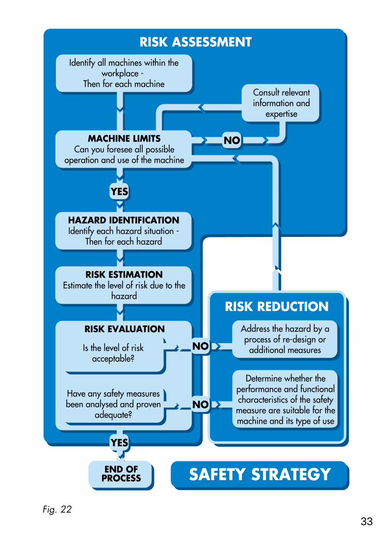
Fig. 22
RISK ASSESSMENT
RISK REDUCTION
NO
YES
END OFPROCESS
MACHINE LIMITSCan you foresee all possible
operation and use of the machine
HAZARD IDENTIFICATIONIdentify each hazard situation -
Then for each hazard
RISK ESTIMATIONEstimate the level of risk due to the
hazard
RISK EVALUATION
Identify all machines within the workplace -
Then for each machine
Have any safety measures been analysed and proven
adequate?
Is the level of risk acceptable?
NO
NO
Determine whether the performance and functional characteristics of the safety measure are suitable for the machine and its type of use
Address the hazard by a process of re-design or
additional measures
Consult relevant information and
expertise
YES
SAFETY STRATEGY
33

routed and protected in a manner which prevents any foreseeable shortcircuits or earth faults. This system will satisfy the requirements of category 1.
Fig. 37CATEGORY 1Fig. 37 shows a slightly more complex circuit. In this case there is arequirement for the interlock device to control more than one contactor, eachbeing on a different power circuit. Its component parts must be given thesame considerations.With a non-safety related circuit an ordinary relay could be used to “split” thesignal but where safety is concerned this would definitely not be acceptableas they can (and sometimes do) stick. Therefore a monitoring safety relay unitsuch as the Guardmaster MINOTAUR MSR5T is used to provide an ensuredswitching action. This system will satisfy the requirements of category 1.
Fig. 38
START STOP
GUARDINTERLOCK SWITCH
MINOTAUR MSR6R (Reset mode)SAFETY RELAY MONITORING UNIT
K1
START STOP
GUARDINTERLOCK SWITCH
MINOTAUR MSR5TSAFETY RELAY MONITORINGUNIT
K1
K2
54

35
together with the types of hazard present. At this stage it is only the identityand type of hazard that concerns us. It is tempting to start estimating thedegree of risk posed by the hazard but this should be dealt with as a separateprocess of risk estimation.
RISK ESTIMATION
This is one of the most fundamental aspects of the safety of machinery. Thereare many ways of tackling this subject and the following pages give a simplebut effective approach and serve to illustrate the basic principles. The methodshould be amended as necessary to suit the requirements of individualsituations. An understanding of both its importance and method is absolutelyessential.
All machinery that contains hazards presents risk. It is important to be able todescribe at which point the risk lies on a relative scale from minimum tomaximum. The following pages provide a practical method for achieving this.It has been shown to be both simple to use and reliable as a guideline to alogical approach. First, let us look at some of the fundamental points.
1- The risk estimation must always be documented.It is tempting to make a purely intuitive judgement. Whilst this may often bebased on experience it almost certainly will not take into account all thenecessary considerations and cannot be easily checked or passed on toothers.You must follow a logical work pattern, write down the results and get otherparties to check it. Remember, it is your evidence that you have shown duediligence in the task.
2 - What is risk?The term risk is often confused with the severity of an accident. Both theseverity of potential harm AND the probability of its occurrence have to betaken into account in order to estimate the amount of risk present.
3 - It must take into account all foreseeable factors.As with the Hazard Identification stage it is important to consider all stages ofthe life of a machine including installation, commissioning, maintenance, de-commissioning, correct use and operation as well as the consequences ofreasonably foreseeable misuse or malfunction.

integrated circuits. More sophisticated types (and hence with more features)may also depend on programmable devices and software.To anticipate and eliminate all dangerous faults in an electronic but non-programmable device would be a huge task and with a programmabledevice it would be virtually impossible. Therefore we must accept that faultswill be possible and the best answer is to detect them and ensure that thenecessary protective action is taken (e.g. locking out to a safe state). So wewould need a device that satisfies the requirements of category 2, 3 or 4.With a simple circuit such as in fig. 35 the light curtain will also monitor thewiring and contactors. As all light curtains are relatively complex, the choiceof categories will usually depend solely on the results of the risk assessment.This does not preclude the fact that it may be possible to work to a differentcategory if a device uses an unconventional but provable approach.
We can see from the last two examples that the same degree of protection isprovided by two types of systems using devices satisfying differentcategories.
Hopefully these examples will encourage a pattern of logic to enable thecorrect decision to be made.
52

37
1 - THE SEVERITY OF POTENTIAL INJURY.For this consideration we are presuming that the accident or incident hashappened. Careful study of the hazard will reveal what is the most severeinjury that can be reasonably envisaged.
Fig. 23Remember: For this consideration we are presuming that an injury isinevitable and we are only concerned with its severity.
The severity of injury should be assessed as:FATALMAJOR - (Normally irreversible) Permanent disability, loss of sight, limb amputation, respiratory damage etc.SERIOUS - (Normally reversible) Loss of consciousness, burns, breakages etcMINOR - Bruising, cuts, light abrasions etc.
Fig. 24 Values are assigned as above.
3 6 101
MINORSERIOUS
MAJORFATAL
In this example most severe injury would be "fatal".
In this example the probable most severe injury would be "serious". With the possibility of bruising, breakage, finger amputation or injury from ejected chuck key etc.
HOWBAD

The wiring which connects the components together must also beconsidered. Undetected short circuit and earth faults could lead to adangerous condition but if it is properly designed and installed usingstandards such as BS EN 60204 for guidance then the chances of failure aregreatly reduced.
This system can provide a significant level of safety which will be adequatefor many situations. You will have noticed however that both the contactorand the wiring are prone to unlikely though theoretically foreseeable faults. Insome cases it may be possible, by taking precautions (e.g. with regard tocable protection and routing) to eliminate all fault possibilities. If this is notfeasible then techniques relevant to categories 2, 3 & 4 such as duplicationand monitoring are usually both more practicable and cost effective.
Fig. 34
Fig. 34 shows a system which fulfils the requirements of category 3. AGuardmaster MINOTAUR MSR6RT safety monitoring relay unit is used tomonitor a two channel control circuit. Any single fault on the wiring orcontactors will be detected by the Minotaur at the next demand on the safetyfunction. NOTE: Although the interlock switch now has double pole contacts itis still a device which fulfils the requirements of category 1 - forming part ofa system which fulfils the requirements of category 3.
This poses the inevitable question of when, and to what degree, do we needto take such measures.
The simple answer is to say that it depends on the results of the riskassessment. This is the correct approach but we must understand that this
MachineControls
InterlockSwitch
PowerContactors
MINOTAURMSR6RTSAFETYRELAY
MONITORINGUNIT
50

39
2b - PROBABILITY OF INJURYYou should assume that the operator is exposed to the hazardous motion orprocess.
Fig. 27By considering the manner in which the operator is involved with the machineand other factors such as speed of start up etc. the probability of injury canbe classed as :UNLIKELYPOSSIBLEPROBABLECERTAIN
Fig. 28 Values are assigned as above.
4 62
1UNLIKELY
POSSIBLEPROBABLE
CERTAIN
HOWLIKELY
In this example the probability of injury could be rated as "certain" because of the amount of body in the hazard area and the speed of machine operation.
In this example the probability of injury may be rated as "possible" as there is minimal contact between the hazard and the operator. There may be time to withdraw from the danger.

So how do you decide on which category you need?
In order to translate these requirements into a system design specificationthere has to be an interpretation of the basic requirements.
First of all let us dispose of one popular misconception. It is a commonly heldbelief that category 1 gives the least protection and category 4 gives the best.This is not the reasoning behind the categories. They are intended asreference points which describe the functional performance of differentmethod types of safety related control system (or their constituent parts).
Category 1 is aimed at the PREVENTION of faults. It is achieved bythe use of suitable design principles, components and materials. Simplicity ofprinciple and design together with the use of materials with stable andpredictable characteristics are the keys to this category.
Categories 2, 3 and 4 require that if faults cannot be preventedthey must be DETECTED (and appropriate action taken). Monitoringand checking are the keys to these categories. The most usual (but not theonly) method of monitoring is to duplicate the safety critical functions (i.e.redundancy) and compare their operation.Perhaps the best way to make further progress is to use examples.
The example in fig. 33 is a simple system comprising a guard door interlockswitch connected in series to the control coil of a power contactor.If we consider that the aim is toward complete reliability with no possibility ofa failure to a dangerous condition, which of the categories is mostappropriate?
The diagram below also shows the location and nature of potential dangerousfaults.
Fig. 33
MachineControls
InterlockSwitch
PowerContactor Short circuit or
earth fault
Contactor sticking fault
48

41
Fig. 30The results of any additional factors are then added to the previous total asshown.
61
6
HIGH
MEDIUM
LOW
Add points equivalent to themaximum frequency factor.
Very long intervals (e.g. 1 year)between access. (There may beprogressive and undetectedfailures particularly in monitoringsystems).
Add 2 points to the total.Operator is unskilled or untrained.

Chapter 5SAFETY RELATED CONTROL SYSTEMS
First of all what is a safety related control system? (often abbreviated toSRCS).
It is that part of the control system of a machine which prevents a hazardouscondition from occurring. It can be a separate dedicated system or it may beintegrated with the normal machine control system. Its complexity will vary from a typical simple system, such as a guard doorinterlock switch and emergency stop switch connected in series to the controlcoil of power contactor, to a compound system comprising both simple andcomplex devices communicating through software and hardware.
In order to provide the safety function the system must continue to operatecorrectly under all foreseeable conditions.
So how do we design a system to achieve this, and when we have done that,how do we show it?
The draft European Standard prEN 954-1 “Safety related parts of controlsystems” deals with these aspects.
It lays down a “language” of five categories for benchmarking and describingthe performance of SRCSs.
Table 32 is a summary of the categories.
46

43
near to dangerous parts (as an alternative to guarding them).
Personal Protection Equipment.- In addition to the above measures itmay also be necessary for the operator to use equipment such as specialgloves, goggles, respirators etc. The machinery designer should specify whatsort of equipment is required. The use of personal protective equipment willnot usually form the primary safeguarding method but will complement themeasures shown above.
Each measure from the hierarchy should be considered in turn starting fromthe top and used where practicable. This may result in a combination ofmeasures being used.
If access is not required to dangerous parts the solution is to protect them bysome type of fixed enclosing guarding.
If access is required then life becomes a little more difficult. It will benecessary to ensure that access can only be gained whilst the machine is safe.Protective measures such as interlocked guard doors and/or trip systems willbe required. The choice of protective device or system should be heavilyinfluenced by the operating characteristics of the machine. This is extremelyimportant as a system which impairs machine efficiency will render itself liableto unauthorised removal or by-passing.
The safety of the machine in this case will depend on the proper applicationand correct operation of the protective system even under fault conditions.The proper application has now been dealt with by the appropriate choice ofgeneral type of protective system. The correct operation of the system must now be considered. Within eachtype there is likely to be a choice of technologies with varying degrees ofperformance of fault monitoring, detection or prevention.
In an ideal world every protective system would be perfect with absolutely nopossibility of failing to a dangerous condition. In the real world however weare constrained by the current limits of knowledge and materials. Anothervery real constraint is, of course, cost. It becomes obvious, because of thesefactors that a sense of proportion is required. Common sense tells us that itwould be ridiculous to insist that the integrity of a safety system on a machinethat may, at the worst case, cause mild bruising to be the same as that

44
required to keep a Jumbo jet in the air. The consequences of failure aredrastically different and therefore we need to have some way of relating theextent of the protective measures to the level of risk obtained at the riskestimation stage.
Whichever type of protective device is chosen It must be remembered that a“safety related system” may comprise many elements including the protectivedevice, wiring, power switching device and sometimes parts of the machine’soperational control system. All these elements of the system (including guards,fixings, wiring etc) should have suitable performance characteristics relevantto their design principle and technology.Draft standard prEN 954-1 outlines various categories for safety related partsof control systems. The next chapter has more information on this subject.
One of the most commonly encountered errors is the belief that a high risklevel always equates directly to a high category level. As we will see in thenext chapter this is not necessarily always the case.
The table shown at fig. 31 is a suggestion for part of a documented processof accounting for all safety aspects of the machinery being used. It acts as aguide for machinery users but the same principle can be used by machinemanufacturers or suppliers. It can be used to confirm that all equipment hasbeen considered and it will act as an index to more detailed reports on riskassessment etc.
It shows that where a machine carries the CE mark it simplifies the process asthe machine hazards have already been considered by the manufacturer andthe necessary measures have been taken. Even with CE marked equipmentthere may still be hazards due to the nature of its application or materialbeing processed which the manufacturer did not foresee.

45
Fig. 31
Com
pany
- M
AY
KIT
WR
IGH
T L
TD
Fac
ility
-
Tool r
oom
- Eas
t Fac
tory.
Dat
e -
29/8
/95
Ope
rato
r pr
ofile
- A
ppren
tice /
Ful
ly sk
illed.
Equip
ment
identi
ty &
date
Blogg
s cen
tre la
the.
Serial
no.
8390
726
Insta
lled
1978
Blogg
s tur
ret h
ead
milli
ng m
/cSer
ial n
o 173
0429
4Ma
nuf 1
995
Insta
lled
May
95
Dire
ctive
Co
nform
ity
None
claim
ed
M/c D
ir.EM
C Di
r
Accid
ent
histor
y
None
None
Notes
Elect
rical
equipm
ent c
ompli
es wi
th BS
EN
6020
4E
stops
fitted
(repl
aced
1989
)
Haza
rd
type
Mech
anica
l En
tangle
ment
Cutti
ng
Toxic
Cutti
ng
Crus
hing
Actio
n re
quire
d
Fit g
uard
inter
lock
switc
h
Chan
ge to
non
txic t
ype
Supp
ly gl
oves
Move
mach
ine t
o give
en
ough
clear
ance
Imple
mente
d &
inspe
cted -
refer
ence
25/1
1/94
J K
ersh
awRe
port
no 9
567
30/1
1/94
J K
ersh
awRe
port
no 9
714
30/1
1/94
J K
ersh
awRe
port
no 9
715
13/4
/95
J Ker
shaw
Repo
rt no
1006
4
Haza
rd
identi
ty
Chuc
k rota
tion
with
guar
d op
en.
Cutti
ng fl
uid
Swar
f clea
ning
Movem
ent o
f bed
(towa
rds w
all)
Risk
As
smnt
Repo
rt no
.
RA30
2
RA41
6

42
RISK REDUCTION and EVALUATION
Now we must consider each machine and its respective risks in turn and takemeasures to address all of its hazards. Section 1.1.2(b) from schedule 3 of the Machinery Directive explains thatthere are three basic methods to be considered and used in the followingorder:-
— Eliminate or reduce risks as far as possible by inherently safe machinery design.
— Take the necessary protection measures in relation to risks that cannot beeliminated.
— Inform users of the residual risks due to the shortcomings of the protectionmeasures adopted, indicate whether any particular training is requiredand specify the need to provide personal protection equipment.
If the machine is still at the design stage it may be possible to eliminate thehazard by a change of approach.
If design methods cannot provide the answer other action needs to be taken.
The types of measures to be considered are given for us in more detail inRegulation 11 (2) HIERARCHY OF MEASURES from P.U.W.E.R. (Provision &use of work equipment regulations 1992) :-
(a) Fixed enclosing guards.
(b) Movable (interlocked) guards or protection devices e.g. light curtains,footmats etc.
(c) Protection appliances (jigs, holders, push sticks etc). - Used to feed aworkpiece whilst keeping the operators body clear of the danger zone. Oftenused in conjunction with guards.
(d) Provision of information, instruction, training and supervision. It is important that operators have the necessary training in the safe workingmethods for a machine. This does not mean that measures (a), (b) or (c) canbe omitted . It is not acceptable merely to tell an operator that he must not go

Table 32Note 1: Category B in itself has no special measures for safety but it forms the base for the other categories. Note 2: Multiple faults caused by a common cause or as inevitable consequences of the first fault shall be counted as asingle fault.Note 3: The fault review may be limited to two faults in combination if it can be justified but complex circuits (e.g.microprocessor circuits) may require more faults in combination to be considered.
CATEGORY B (see note 1)- Safety related parts of machine control systems and/or their protective equipment, as well as their components, shall be designed, constructed, selected, assembled and combined in accordance with relevant standards so that they can withstand the expected influence.
CATEGORY 2- The requirements of category B and the use of well tried safety principles apply.- The safety function(s) shall be checked at machine start-up and periodically by the machine control system. If a fault is detected a safe state shall be initiated or if this is not possible a warning shall be given.
CATEGORY 1- The requirements of category B apply together with the use of well tried safety components and safety principles.
CATEGORY 3 (see notes 2 & 3)- The requirements of category B and the use of well tried safety principles apply.- The system shall be designed so that a single fault in any of its parts does not lead to the loss of safety function.
CATEGORY 4 (see notes 2 & 3)- The requirements of category B and the use of well tried safety principles apply.- The system shall be designed so that a single fault in any of its parts does not lead to the loss of safety function.-The single fault is detected at or before the next demand on the safety function. If this detection is not possible then an accumulation of faults shall not lead to a loss of safety function.
When a fault occurs it can lead to a loss of the safety function.
The loss of safety function is detected by the check.
The occurrence of a fault can lead to the loss of safety function between the checking intervals.
As described for category B but with higher safety related reliability of the safety related function. (The higher the reliability, the less the likelyhood of a fault
When the single fault occurs the safety function is always performed.
Some but not all faults will be detected.
An accumulation of undetected faults can lead to the loss of safety function.
When the faults occur the safety function is always performed.
The faults will be detected in time to prevent the loss of safety functions.
By se
lectio
n of
comp
onen
ts(T
owar
ds P
REVE
NTIO
N of
fault
s)By
stru
cture
(Tow
ards
DET
ECTIO
N of
fault
s)
SUMMARY OF REQUIREMENTS SYSTEM BEHAVIOUR PRINCIPLE
47

40
All headings are assigned a value and they are now added together to givean initial estimate. For example:-
Fig. 29 (Note: This is not based on the previous example pictures).
The next step is to adjust the initial estimate by considering additional factorssuch as those shown below. Often they can only be properly consideredwhen the machine is installed in its operation location. Depending on the type and usage of the machinery there may be otherrelevant factors which should also be listed and considered at this stage.
TYPICAL FACTOR SUGGESTED ACTION
If time spent per access is more than15mins add 1 point to the frequencyfactor.
Protracted time in the danger zonewithout complete power isolation.
Multiply the severity factor by thenumber of people.
More than one person exposed tothe hazard.
61
6

If we refer to table 32 which type of category is the most appropriate? Theprevention of faults or the detection of faults?
The first step is to separate the system into its major components and considertheir modes of potential failure.
In this example the components are:Interlock switch.Contactor.Wiring.
The interlock switch is a mechanical device. The task which it performs isa simple one i.e. opening the contacts when a guard door is opened. It fulfilsthe requirements of category 1 and by the use of correct design principlesand materials it can be proved that, when used within its stated operatingparameters, it will have no failures to a dangerous condition. This is madefeasible by the fact that the device is relatively simple and has predictableand provable characteristics.
The contactor is a slightly more complex device and may have sometheoretical possibilities for failure. Contactors from reputable manufacturersare extremely reliable devices. Statistics show that failures are rare and canusually be attributed to poor installation or maintenance.
Contactors should always have their power contacts protected by anovercurrent cut-out device to prevent welding.
Contactors should be subject to a regular inspection routine to detectexcessive contact pitting or loose connections which can lead to overheatingand distortion.
It should be checked that the contactor complies with relevant standards whichcover the required characteristics and conditions of use.
By attending to these factors it is possible to keep the possibilities of failure toa minimum. But for some situations even this is unacceptable and in order toincrease the level of safety provision we need to use duplication andmonitoring.
49

38
2a - FREQUENCY OF EXPOSURE
Fig. 25The frequency of exposure to hazard can be classed as :
FREQUENT - Several times per day.OCCASIONAL - Daily.SELDOM - Weekly or less.
Fig. 26 Values are assigned as above.
421SELDOM
OCCASIONAL
FREQUENT
HOWOFTEN

includes all factors and not just the level of risk at the hazard point. Forexample, it may be thought that if the risk estimation shows a high level ofrisk, the interlock switch should be doubled up and monitored. But in manycircumstances this device, due to its application, design and simplicity, willnot fail to a danger and there will be no undetected faults to monitor.
Therefore the situation is becoming clear, the type of category used willdepend on both the risk assessment and the nature andcomplexity of the device or system. It is also clear that where a totalsystem meets the requirements of category 3 for example it may includedevices to category 1.
If there are fault possibilities the higher the degree of risk, obtained at therisk estimation, the greater the justification for measures to prevent ordetect them and the type of category should be chosen to give the mostsuitable and efficient method of doing this. Remember, the level of riskestimate is one factor but the nature of the protective device or system and themachine’s operating characteristics must also be taken into account.
Fig. 35
Fig. 35 shows the same basic circuit but the interlock switch is replaced by asafety light curtain.
The safety light curtain is a complex device. Even in its simplest form itwill have a relatively large number of electronic components including
MachineControls
Safety light curtain PowerContactors
SAFETYLIGHT
CURTAINCONTROLSYSTEM
51

36
4 - It is an iterative process but work need not be repeated needlessly.For example: A machine has a guard door with an interlocking system which,during an earlier risk evaluation, has been shown to be satisfactory. Providedthat there are no changes which affect it, during subsequent risk assessmentsno further measures will be required as the risk has been satisfactorilyreduced (or eliminated).But if the machine has never been subjected to a formal risk assessment or itsusage circumstances have altered then it cannot be automatically assumedthat the interlocking system is satisfactory and the risk estimation should berepeated to verify (or otherwise) its suitability.
The suggestion for risk estimation given on the following pages is notadvocated as the definitive method as individual circumstances may dictate adifferent approach. IT IS INTENDED ONLY AS A GENERAL GUIDELINE TOENCOURAGE A METHODICAL AND DOCUMENTED STRUCTURE.It is intended to explain and complement the risk estimation section in draftstandard prEN 1050 “Principles for Risk Assessment” It uses the same wellestablished principles as the standard but has a few minor variations in thedetailed approach. This reflects the fact that it has been strongly influenced bythe need to develop a method which is straightforward and reliable and isspecifically intended for assisting in the selection of protective systems.A series of excellent guidance books are produced by the HSE which dealwith certain types of machines. If the type of machinery in question is coveredby one of these books the relevant recommendations should be followed.
The following factors are taken into account:1 - THE SEVERITY OF POTENTIAL INJURY.2 - THE PROBABILITY OF ITS OCCURRENCE.
The probability of occurrence comprises two factors:a - FREQUENCY OF EXPOSURE.b - PROBABILITY OF INJURY.
Dealing with each factor independently we shall assign values to thesefactors.
Make use of any data and expertise available to you. You are dealing withall stages of machine life so base your decisions on the worst case.Remember, for the purposes of this exercise, you should assume that aprotective system has not been fitted or has failed to danger. Therefore, forexample, the machine power may not be isolated when a guard is opened ormay even start up unexpectedly whilst the guard is open.

Chapter 6FURTHER CONSIDERATIONS AND EXAMPLES
In this section we shall give examples of safety related control circuits withreference to recommended practices and the safety related control systemcategories where appropriate. General requirementsThe system must be capable of withstanding all expected influences. Thesewill include temperature, environment, power loading, frequency of use,airborne interference, vibration etc. The standard BS EN 60204-1 “Safety ofmachinery - Electrical equipment of machines - Specification for generalrequirements” provides detailed guidance on such things as electric shockprotection, wiring practices, insulation, equipotential bonding, equipment,power supplies, control circuits and functions etc. A knowledge of thisstandard is essential for those concerned with the design and maintenance ofsafety related control systems.
Circuits and Monitoring Safety Relay UnitsThe examples given below are based on the use of a control interlockingswitch but the same principle can be applied to other switching device e.g.emergency stop or trip devices.
Fig. 36CATEGORY 1Fig. 36 shows a simple safety related control circuit . The interlock device haspositive mode operation and satisfies the requirements of category 1. Thecontactor is correctly selected for its duty and is designed and manufacturedto specific standards. The part of the system most prone to a fault is theconnecting wiring. In order to overcome this it should be installed inaccordance with the relevant clauses of standard BS EN 60204. It should be
START STOP
GUARDINTERLOCK SWITCH
K1
53

34
RISK ASSESSMENT
Why is a risk assessment necessary?One reason is obvious - it is a legal requirement. Most of the directivesand regulations regarding machinery safety state that a formal risk assessmentshould be carried out. Most of the harmonised European A & B typestandards refer to it and the subject itself has a standard - prEN 1050“Principles for Risk Assessment” (in draft form at the time of printing thisbook). There can be few people concerned with the safety of machinery whodo not realise the importance of risk assessment and as we have established itis an integral part of a safety strategy.
It is wrong to regard risk assessment as a burden. It is a helpful process whichprovides vital information and empowers the user or designer to take logicaldecisions about ways of achieving safety.
MACHINE LIMIT DETERMINATION and HAZARD IDENTIFICATION
A complete list of all machines should be made. Where separate machinesare linked together, either mechanically or by control systems, they should beconsidered as a single machine. Each machine is then considered in turn tosee if it presents any sort of hazard and the list marked accordingly.
It is important to consider all limits and stages of the life of a machineincluding installation, commissioning, maintenance, de-commissioning, correctuse and operation as well as the consequences of reasonably foreseeablemisuse or malfunction.
All types of hazard must be considered including crushing, shearing,entanglement, part ejection, fumes, radiation, toxic substances, heat , noiseetc.
NOTE: If a machine relies on anything other than its intrinsic nature for itssafety it should be indicated as a hazard source. A machine with exposedgears has an obvious and direct hazard. But if the gears are protected by aninterlocked access panel they are a potential hazard which may become anactual hazard in the event of failure of the interlocking system.
Each machine with a hazard should be identified and marked on the list

CATEGORY 2Fig. 38 shows a system which satisfies the requirements of category 2 andtherefore must undergo a test of the safety function before the machine can bestarted. It must also be tested periodically. At initial power up the Minotaurwill not allow switching of power to the contactor until the guard is openedand closed. This initiates a check for any single faults in the circuit from theswitch to the Minotaur. Only when this check is successful will the contactorbe energised. At every subsequent guard operation the circuit will be similarlychecked.
Fig. 39CATEGORY 3Fig. 39 shows a system which satisfies the requirements of category 3 and isoften suitable for applications with higher risk estimations. It is a dual channelsystem which is fully monitored including the two contactors. On opening andclosing the guard, any single dangerous fault will cause the Minotaur to lockoff power to the contactors until the fault is rectified and the Minotaur is reset.
CATEGORY 4Category 4 requires that the safety system function is still provided even withan accumulation of undetected faults (see page 47). The most practicable wayof achieving this is to employ continuous or high frequency monitoringtechniques. This is not feasible with most mechanical or electro-mechanicalcomponents (e.g. mechanical switches, relays, contactors) such as are used ininterlocking and emergency stop systems.These techniques are viable (and often used) to monitor solid state electronic
START STOPGUARDINTERLOCK SWITCH
MINOTAUR MSR6TSAFETY RELAY MONITORING UNIT
K1
K2
CONTACTORS
55

process is still carried out to ensure that everything is considered.
Although this section may only seem to apply to machine manufacturers it isalso relevant to machine users as machines are often used in circumstancesunforeseen by the manufacturer. The user (or employer) has a statuaryrequirement to provide a safe working environment. The P.U.W.E.R.regulation 5 (guidance paragraph 60) makes it clear that the safety of workequipment is addressed from three aspects : (a) its initial integrity (b) the place where it is used (c) the purpose for which it is used.For example, a milling machine used in a school workshop will needadditional considerations to one which is used in an industrial tool room. It should also be remembered that if a user company acquires two ore moreindependent machines and integrates them into one process they are,technically speaking, the manufacturer of the resulting combined machine.
So now let us consider the essential steps on the route to a proper safetystrategy. The following can be applied to an existing factory installation or asingle new machine.
32

and expensive or, at worst, be impossible.The draft standard IEC 1508 deals with this subject in great detail andanyone concerned with safety related programmable systems is advisedto study it when it becomes available.The development costs of these systems are justifiable in applicationswhere they have significant advantages or no other method will work.
2 - Monitoring Unit with Time Delayed Override Command.(see Fig. 40) This system has the high integrity level of hard wiring andalso allows a correctly sequenced shut-down which protects themachine and program.
Fig. 40The Guardmaster MINOTAUR MSR10RD primary outputs are connectedto inputs at the programmable device (e.g. P.L.C.) and the delayedoutputs are connected to the contactor. When the guard interlock switchis actuated, the primary outputs on the Minotaur switch immediately.This signals the programmable system to carry out a correctlysequenced stop. After sufficient time has elapsed to allow this processthe delayed output on the Minotaur switches and isolates the maincontactor.This range of Guardmaster devices can be used with various protectivedevices and is available with other configurations and switchingarrangements to suit the requirements of particular systems.
Note: Any calculations to determine the overall stopping time must takeaccount of the Minotaur output delay period. This is particularlyimportant when using this factor to determine the positioning of devices
GUARDINTERLOCK SWITCH
MINOTAUR MSR10 RD
Timed delay output
PLC
NORMALMACHINE CONTROLS
MAINCONTACTOR
57

effective to use a grabwire device along the hazard area. These devices use asteel wire rope connected to latching pull switches so that pulling on the ropein any direction at any point on its length will operate the switch and cut offthe machine power.
Telescopic trip switchesOther variations include telescopic antenna switches where deflection of theantenna causes the switch to cut off the machine power. These devices aremore commonly used as trip devices on machinery such as pillar drills. Theswitch is mounted on the drill and the antenna is extended down next to thedrill bit. In the event of the operator becoming entangled with the drill he willbe pulled onto the antenna which operates the switch (usually connected to ad.c. injection braking unit as shown below).
Fig. 21d.c. Injection brake units.On some machinery simply cutting the power via an emergency stop devicewill not cause the machine to stop quickly enough to prevent serious injury. Inthis situation there needs to be some form of rapid braking. One of the mosteffective methods for electrically powered machinery is the dc. injectionemergency brake unit. With this method direct current is injected into themotor in a carefully controlled manner to achieve an extremely rapid stop. Assoon has the motor has stopped, all power to it is cut off.
30

contactor start arrangement as shown in fig. 42 (an interlocked guard door isused as an example here but the requirements apply to other protectiondevices and emergency stop systems).
Fig. 42Pressing and releasing the start button momentarily energises the contactorcontrol coil which closes the power contacts. As long as power is flowingthrough the power contacts the control coil is kept energised (electricallylatched) via the contactor’s auxiliary contacts which are mechanically linkedto the power contacts. Any interruption to the main power or control supplyresults in the de-energising of the coil and opening of the main power andauxiliary contacts. The guard interlock is wired into the contactor controlcircuit. This means that restart can only be achieved by closing the guard andthen switching “ON” at the normal start button which resets the contactor andstarts the machine.
The requirement for normal interlocking situations is made clear in BS EN 292part 1 3.22.4 (extract) -When the guard is closed, the hazardous machine functions covered by theguard can operate, but the closure of the guard does not by itself initiate theiroperation.
Many machines already have either single or double contactors whichoperate as described above (or have a system which achieves the same
INTERLOCK SWITCHshown with guard closed
AUXILIARY CONTACTS
POWER CONTACTS
CONTACTOR
CONTACTORCONTROLCOIL
"START"BUTTON
"STOP"BUTTON
DERIVED CONTACTORCONTROLSUPPLY
3 PHASE POWER TO MACHINE MOTOR
NEUTRAL
59

Pressure sensitive edges
Fig. 18These devices are flexible edging strips which can be fixed to the edge of amoving part such as a machine table or powered door where there is a risk ofa crushing or shearing hazard.If the moving part strikes the operator (or vice versa) the flexible sensitiveedge is depressed and will switch off the hazard power source. Sensitiveedges can also be used to guard machinery where there is a risk of operatorentanglement. If an operator becomes caught up and dragged by themachine he will be pulled onto the sensitive edge thereby tripping itsswitching action and causing power to the machine to be cut off.
Light curtains, footmats and sensitive edges can all be classed as “tripdevices”. They do not actually restrict access but only “sense” it. They relyentirely on their ability to both sense and switch for the provision of safetytherefore it is important that their control circuit incorporates self monitoringand fail-safe measures. Also they must only be used in correct applications. Ingeneral they are only suitable on machinery which stops reasonably quicklyafter switching off the power source. Because an operator can walk or reachdirectly into the hazard area it is obviously necessary that the time taken forthe motion to stop is less than that required for the operator to reach thehazard after tripping the device.
28

An auto-reset device does not require a manual switching action but afterde-actuation it will always conduct a system integrity check before resettingthe system.An auto-reset system should not be confused with a device without resetfacilities. In the latter the safety system will be enabled immediately after de-actuation but there will be no system integrity check.
Control GuardsA control guard stops a machine when the guard is opened and directly startsit again when the guard is closed. The use of control guards is only allowed under certain stringent conditionsbecause any unexpected start-up or failure to stop would be extremelydangerous. The interlocking system must have the highest possible reliability (itis often advisable to use guard locking).The use of control guards can ONLY be considered on machinery where thereis NO POSSIBILITY of an operator or part of his body staying in or reachinginto the danger zone whilst the guard is closed.The control guard must be the only access to the hazard area.
61

Preventing dangerous motionWhen frequent access is required physical guarding at the hazard issometimes too restrictive for part loading or adjustment. In this situation adevice is required which prevents dangerous motion whilst allowingunrestricted access by sensing the presence of the operator and isolating thepower source.
Photo electric light curtains
Fig. 16These devices emit a “curtain” of harmless infra red light beams in front of thehazard area. When any of the beams are blocked by intrusion towards thehazard area the light curtain control circuit switches off the hazard powersource. There are many factors which affect the type and positioning of a lightcurtain and these are dealt with in the standard prEN 999 “The positioning ofprotective equipment in respect of approach speeds of parts of the humanbody”. It is strongly recommended that the HSE Guidance Note PM 41 “Theapplication of photo-electric safety systems to machinery” is also studied.
Light curtains are extremely versatile and can guard areas many meters wide.By the use of mirrors the light beams can be diverted round corners to enclosea machine. They are available with different light beam spacings makingthem suitable for many applications ranging from totally enclosing perimeterguards for industrial robots, to point of access guard for certain types ofpresses and guillotines.
26

also be a factor at this stage. Switches are available with various levels ofsecurity ranging from resistance to impulsive tampering, to being virtuallyimpossible to defeat.
It should be noted at this stage that if a high degree of security is required it issometimes more practicable to achieve this by the way in which it is fitted.
Fig. 44For example, if the switch is fitted as in fig. 44 with a covering track, there isno access to the switch with the guard door open. The nature of any“cheating” prevention measures taken at the fitting stage will depend on theoperating principle of the switch.
Positive Mode Operation (also referred to as direct operation)BS EN 292-2 3.5 explains that if a moving mechanical component inevitablymoves another component along with it, either by direct contact or via rigidelements, these components are said to be connected in the positive mode.
With single mechanical type interlocking switches, when the guard is openedthe movement of the guard should be connected in the positive mode to thesafety related contacts of the switch. This ensures that the contacts arephysically pulled apart or “force disconnected” by the movement of theguard.
The switch should NOT rely solely on spring pressure to open the contacts as
63

Movable guards with interlocking switches
Fig. 14If access is required there needs to be a movable (openable) guard which isinterlocked with the power source of the hazard in a manner which ensuresthat whenever the guard door is not closed the hazard power will be switchedoff. This approach involves the use of an interlocking switch fitted to the guarddoor. The control of the power source of the hazard is routed through theswitch section of the unit. The power source is usually electrical but it couldalso be pneumatic or hydraulic. When guard door movement (opening) isdetected the interlocking switch will isolate the hazard power supply eitherdirectly or via a power contactor (or valve).
Some interlocking switches also incorporate a locking device which locks theguard door closed and will not release it until the machine is in a safecondition. For the majority of applications the combination of a movableguard and an interlock switch with or without guard locking is the mostreliable and cost effective solution.
24

directly operate the contacts whenever the guard door is open. Spring pressurecan only close the contacts when the guard is fully closed. Any spring breakagewill only result in a failure to a safe condition.
EnclosureThe positive mode operation principle shown in fig. 46 is used wherever it isrelevant in Guardmaster interlock switches. They also avoid any possible abuseby enclosing the contact block and cam in a strong and secure enclosure. Thismeans that the cam and the contact block cannot become separated and it isimpossible to defeat the switch by cutting another slot in the cam.
Fig. 47The principle is adapted further for tongue operated interlock switches asshown in fig. 47. These devices are widely used as they are simple to fit atthe opening edge of the guard and can be used on sliding, hinged andremovable guard doors. The actuator tongue is mounted on the guard doorand opening the guard causes the tongue to force disconnect the contacts.The switch mechanism is mounted in an enclosure and the tongue actuatingprinciple is designed to resist tampering.
Fitness for PurposeAs a minimum, all designs and materials must be able to withstand theexpected operating stresses and external influences.
Other Safety PrinciplesFor non mechanical devices there is usually no physical contact between theswitch and actuation method. Therefore positive mode operation cannot beused as the way of ensuring the switching action and we need to use othermethods as follows.
FORCED DISCONNECTION
65

for the manufacture of discrete parts or assemblies. It is based on theInternational Standard ISO 11161:1994.
prEN 61496-1&2 - Safety of machinery - Electro sensitiveprotective equipment Pt 1: General requirements and tests.Pt 2: Particular requirements for equipment using active opto-electronic protective devices.Part 1 gives requirements and test procedures for the control and monitoringaspects for electro sensitive protective equipment. Subsequent parts deal withaspects particular to the sensing side of the system.Part 2 gives particular requirements for safety light curtains.
prEN 1760-1 - Safety of machinery - Pressure Sensitive SafetyDevices - Pt 1: Mats & Floors. .Gives requirements and test procedures.
prEN 1760-2 - Safety of machinery - Pressure Sensitive SafetyDevices - Pt 2: Edges & Bars. Gives requirements and test procedures.
prEN 953 - Safety of machinery - General Requirements for theDesign and Construction of Guards.Gives definitions, descriptions and design requirements for fixed and movableguards.
prEN 1037 - Safety of machinery - Isolation and energydissipation - Prevention of unexpected start-up.Defines measures aimed at isolating machines from power supplies anddissipating stored energy to prevent unexpected machine start-up and allowsafe intervention in danger zones.
22

TYPICAL FORMS OF INTERLOCKING DEVICES
Fig. 49
In the broadest terms there are two basic types of electrical interlockingsystems:
Power interlocking - The power source of the hazard is directlyinterrupted due to the opening of the guard.
Control interlocking - The power source of the hazard is interrupted bythe switching of a circuit which controls the power switching device.
The following text deals with the interlocking of electrical power supplies asthis is by far the most common requirement but the same basic principles canbe applied to hydraulic and pneumatic systems.
POWER INTERLOCKINGThe movement of the guard is interlocked with the direct switching of thepower to the hazard. For equipment using low voltage and power most typesof interlock switch can be used for power interlocking. But because mostindustrial machinery uses a relatively high power three phase supply we needpurpose designed power interlocking systems with the power interruptingswitch capable of handling and breaking the load reliably.
CONTROL INTERLOCKING
WITH GUARD LOCKING
POWER INTERLOCKING
WITHOUT GUARD LOCKING
MECHANICALDEVICES
NON-CONTACT DEVICES
UNCONDITIONAL GUARD
UNLOCKING
CONDITIONAL GUARD
UNLOCKING
67

BS EN 292 pts 1&2 - Safety of machinery - Basic concepts,general principles for design. Absolute compulsory reading for all. It is an A standard which outlines all thebasic principles including risk assessment, guarding, interlocking, emergencystops, trip devices, safety distances etc. (and much more). It references out tothe other standards and also includes the essential safety requirements fromthe Machinery Directive.
BS EN 60204-1 - Safety of machinery - Electrical equipment ofmachines - Pt 1 General requirements.This is a very important standard. It gives general and specificrecommendations for safety related aspects of wiring and electrical equipmenton machines.
BS EN 294 - Safety of machinery - Safety distances to preventdanger zones being reached by the upper limbs.Gives data for calculation of safe aperture sizes and positioning for guardsetc.
prEN 811 - Safety of machinery - Safety distances to preventdanger zones being reached by the lower limbs.Gives data for calculation of safe aperture sizes and positioning for guardsetc.
prEN 349 - Safety of machinery - Minimum distances to avoidcrushing parts of the human body.Gives data for calculation of safe gaps between moving parts etc.
prEN 1088 - Safety of machinery - Interlocking devicesassociated with guards - Principles for design and selection.Gives principles for the design and selection of interlocking devicesassociated with guards.In order to verify mechanical switches it refers to BS EN 60947-5-1 - Lowvoltage switchgear - Pt 5: Control circuit devices and switchingelements - Section 1: Electromechanical control circuit devices.In order to verify non-mechanical switches it refers to prEN 60947-5-3 -Particular requirements for proximity devices with faultprevention measures or defined behaviour under faultconditions. (Provisional number and title only).
20

Fig. 51The use of a personnel key ensures that the operator cannot be locked in theguarded area. The key can also be used for robot teach mode switches, inchmode controls etc.
Fig. 52Double access guard doors interlocked with the Power Isolation Switch. Key“A” is trapped in the isolation switch. Both “B” keys are trapped in a KeyExchange Unit. Power is ON and there is no access available to the machinethrough the locked guard doors.
MACHINE IS NOW STOPPED AND THEELECTRICAL SUPPLY HAS BEEN ISOLATED.ACCESS DOOR CAN NOW BE OPENED.WHEN DOOR IS OPEN KEY A IS TRAPPEDKEY B IS TAKEN INTO THE GUARDED AREA TO ENSURE THE DOOR CANNOT BE LOCKED BY A THIRD PARTY.
KEY TRAPPED MAIN SUPPLY ON
A A
ELECTRICAL SUPPLYLOCKED OFF
A
MACHINE IS RUNNING.ELECTRICAL SUPPLY IS ON.ACCESS DOOR IS LOCKED.
69

Chapter 2 HARMONISED EUROPEAN STANDARDS
These standards are common to all EC and EFTA countries and are producedby the European Standardisation bodies CEN and CENELEC . Their use isvoluntary but designing and manufacturing equipment to them is the mostdirect way of demonstrating compliance with the EHSRs. At the time of publication of this book some of the standards are not yetcompleted but as they become available their titles will be published in theOfficial Journal of the European Communities. Details will also be given inpublications such as BSI News. They will have a common prefix of EN and inthe UK they will be prefixed BS EN. When they are published, existingnational standards which have the same scope will be withdrawn.
They are divided into 3 groups: A, B and C standards.A STANDARDS - Cover aspects applicable to all types of machines.B STANDARDS - Subdivided into 2 groups.
B1 STANDARDS - Cover particular safety and ergonomic aspects ofmachinery.B2 STANDARDS - Cover safety components and devices.
C STANDARDS - Cover specific types or groups of machines.
It is important to note that complying with a C Standard gives automaticpresumption of conformity with the EHSRs. In the absence of a suitable CStandard, A and B Standards can be used as part or full proof of EHSRconformity by pointing to compliance with relevant sections.
Agreements have been reached with other world-wide Standardisation Bodiesfor co-operation between CEN/CENELEC and bodies such as IEC and ISO.This should ultimately result in common world-wide standards.
18
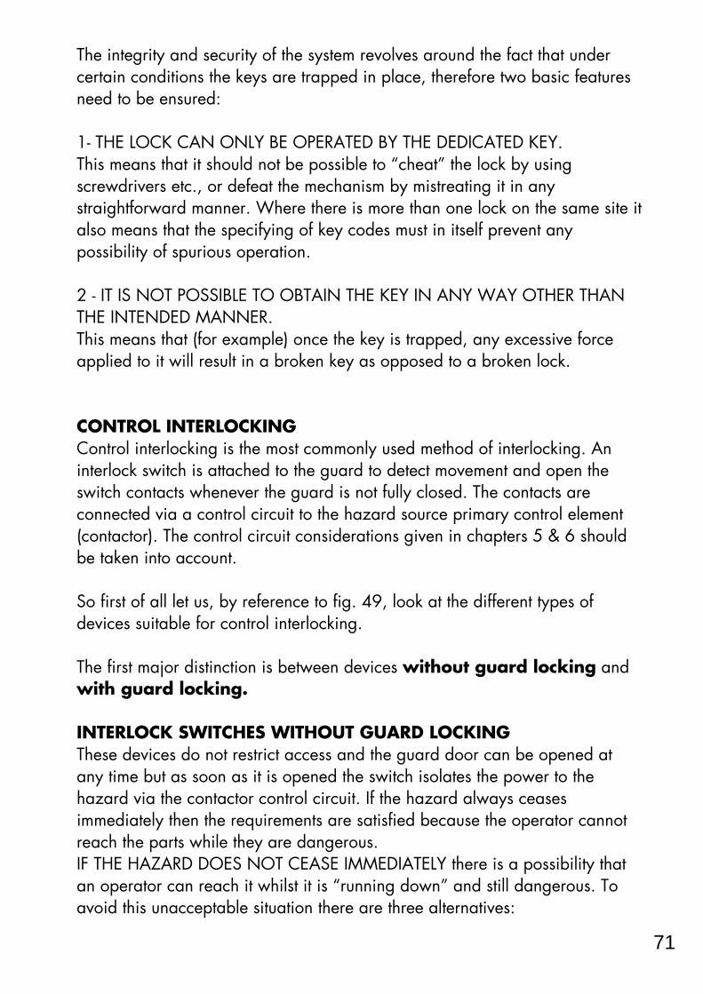
The integrity and security of the system revolves around the fact that undercertain conditions the keys are trapped in place, therefore two basic featuresneed to be ensured:
1- THE LOCK CAN ONLY BE OPERATED BY THE DEDICATED KEY.This means that it should not be possible to “cheat” the lock by usingscrewdrivers etc., or defeat the mechanism by mistreating it in anystraightforward manner. Where there is more than one lock on the same site italso means that the specifying of key codes must in itself prevent anypossibility of spurious operation.
2 - IT IS NOT POSSIBLE TO OBTAIN THE KEY IN ANY WAY OTHER THANTHE INTENDED MANNER.This means that (for example) once the key is trapped, any excessive forceapplied to it will result in a broken key as opposed to a broken lock.
CONTROL INTERLOCKINGControl interlocking is the most commonly used method of interlocking. Aninterlock switch is attached to the guard to detect movement and open theswitch contacts whenever the guard is not fully closed. The contacts areconnected via a control circuit to the hazard source primary control element(contactor). The control circuit considerations given in chapters 5 & 6 shouldbe taken into account.
So first of all let us, by reference to fig. 49, look at the different types ofdevices suitable for control interlocking.
The first major distinction is between devices without guard locking andwith guard locking.
INTERLOCK SWITCHES WITHOUT GUARD LOCKINGThese devices do not restrict access and the guard door can be opened atany time but as soon as it is opened the switch isolates the power to thehazard via the contactor control circuit. If the hazard always ceasesimmediately then the requirements are satisfied because the operator cannotreach the parts while they are dangerous.IF THE HAZARD DOES NOT CEASE IMMEDIATELY there is a possibility thatan operator can reach it whilst it is “running down” and still dangerous. Toavoid this unacceptable situation there are three alternatives:
71

training for the safe use of the machine.New machinery (and second hand machinery from outside the EC or EFTA)provided after 1st January 1993 should satisfy any relevant product directivese.g.. The Machinery Directive (subject to transitional arrangements). Secondhand equipment from within the EC or EFTA provided for the first time in theworkplace must immediately satisfy regulations 11 to 24.NOTE: Existing or second hand machinery which is significantly overhauledor modified will be classed as new equipment so the work carried out on itmust ensure compliance with the Machinery Directive (even if it is for acompany’s own use).
Regulation 5 “Suitability of work equipment” lies at the heart of the directiveand it highlights the employers responsibility (under the Management ofHealth and Safety at Work Regulations 1992) to carry out a proper processof risk assessment.
Regulation 6 “Maintenance” requires machinery to be properly maintained.This will normally mean that there must be a routine and planned preventivemaintenance schedule. It is recommended that a log is compiled and kept upto date. This is especially important in cases where the maintenance andinspection of equipment contributes to the continuing safety integrity of aprotective device or system.
REGULATIONS 11 TO 24These regulations cover specific hazards and protective arrangements onmachines.They will not be fully implemented until 1st January 1997 for existingunmodified machines in use before 1st January 1993. They do applyimmediately to other equipment although if the equipment conforms withrelevant product directives e.g. The Machinery Directive, they willautomatically comply with the corresponding requirements of regulations 11to 24 as they are similar in nature to the EHSRs of that Directive.Of particular interest is Regulation 11 which gives a hierarchy of protectionmeasures. These are:
a Fixed enclosing guards.b Other guards or protection devices.c. Protection appliances (jigs, holders, push sticks etc.).d The provision of information, instruction, supervision and training.
These measures should be applied from the top (a) as far as practical andusually a combination of two or more will be required.
16
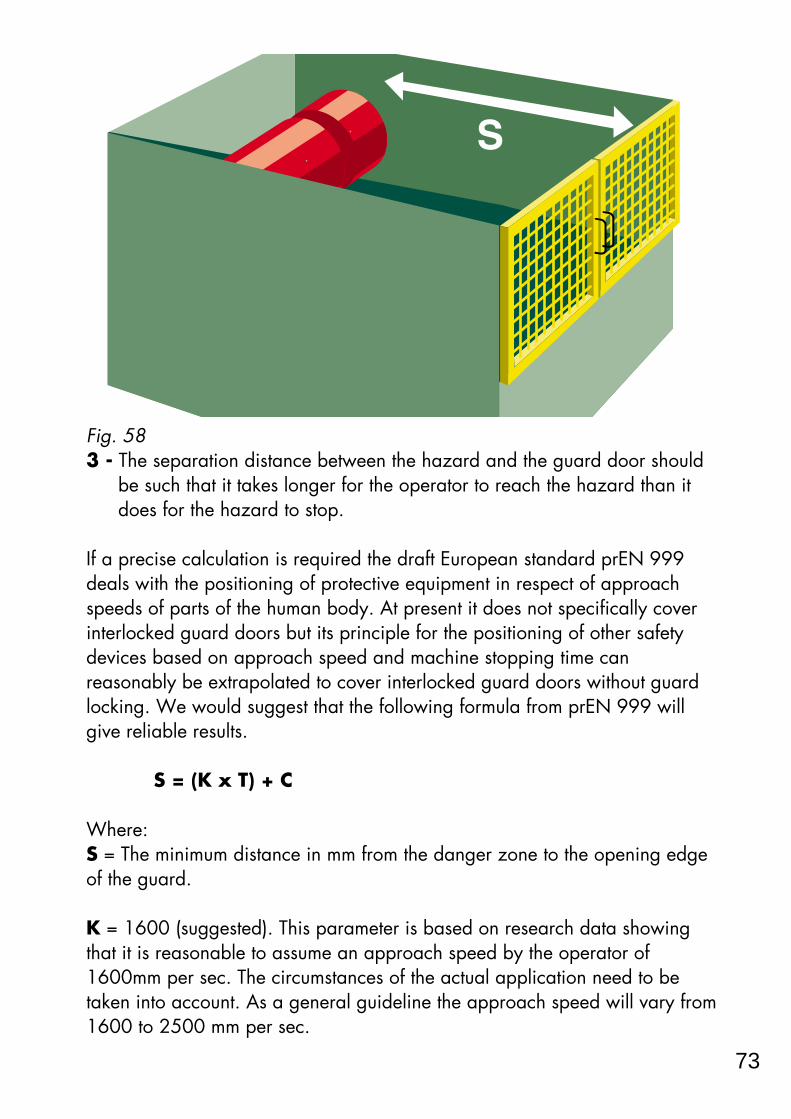
Fig. 583 - The separation distance between the hazard and the guard door should
be such that it takes longer for the operator to reach the hazard than itdoes for the hazard to stop.
If a precise calculation is required the draft European standard prEN 999deals with the positioning of protective equipment in respect of approachspeeds of parts of the human body. At present it does not specifically coverinterlocked guard doors but its principle for the positioning of other safetydevices based on approach speed and machine stopping time canreasonably be extrapolated to cover interlocked guard doors without guardlocking. We would suggest that the following formula from prEN 999 willgive reliable results.
S = (K x T) + C
Where:S = The minimum distance in mm from the danger zone to the opening edgeof the guard.
K = 1600 (suggested). This parameter is based on research data showingthat it is reasonable to assume an approach speed by the operator of1600mm per sec. The circumstances of the actual application need to betaken into account. As a general guideline the approach speed will vary from1600 to 2500 mm per sec.
73
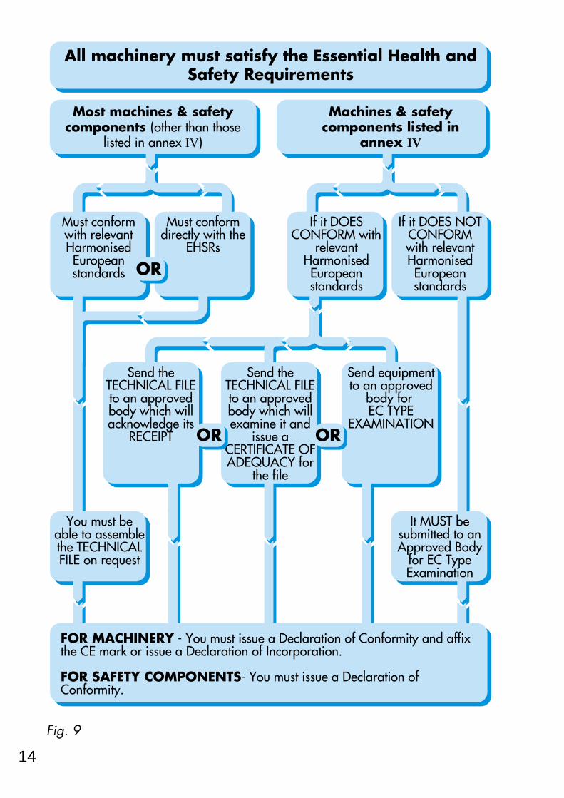
Fig. 9
Must conform directly with the
EHSRs
Most machines & safety components (other than those
listed in annex IV)
All machinery must satisfy the Essential Health and Safety Requirements
Machines & safety components listed in
annex IV
Must conform with relevant Harmonised European standards
If it DOES NOT CONFORM with relevant Harmonised European standards
If it DOES CONFORM with
relevant Harmonised European standards
OR
It MUST be submitted to an Approved Body
for EC Type Examination
FOR MACHINERY - You must issue a Declaration of Conformity and affix the CE mark or issue a Declaration of Incorporation.
FOR SAFETY COMPONENTS- You must issue a Declaration of Conformity.
You must be able to assemble the TECHNICAL FILE on request
Send the TECHNICAL FILE to an approved body which will acknowledge its
RECEIPT
Send equipment to an approved
body for EC TYPE
EXAMINATION
Send the TECHNICAL FILE to an approved body which will examine it and
issue a CERTIFICATE OF ADEQUACY for
the file
OROR
14

Features:The tongue and mechanism are designed to prevent easy cheating of theswitch. These devices are straightforward to install and are very reliable.
They can be used on sliding, hinged and lift-off guards and because oftheir versatility they are one of the most commonly used types of interlockswitches.For consideration:The guard mounted tongue needs to remain reasonably well aligned withthe entry hole in the switch body. Tongue operated switches can bedifficult to clean thoroughly. This may be a problem in industries such asfood manufacturing and pharmaceuticals.
Hinge Operated Actuation
Fig. 60The device is mounted over the hinge-pin of a hinged guard. The openingof the guard is transmitted via a positive mode operating mechanism tothe control circuit contacts.Features:When properly installed these types of switches are ideal for most hingedguard doors where there is access to the hinge centre line. They canisolate the control circuit within 3° of guard movement and they arevirtually impossible to defeat without dismantling the guard.
75

EC DECLARATION OF CONFORMITY
Fig. 8The certificate forming the declaration of conformity must include details ofthe manufacturer and responsible person, details (make serial no. etc.) of themachine, details of the approved body if appropriate, details of anystandards used and the details of the person empowered to sign thedeclaration certificate. It must state conformity with the EHSRs or with theexample of the machinery that underwent EC type examination.
Maykit Wright Ltd.
Declaration of Conformity respect of the following Directives: uropean Machinery Directive (89/392 EEC as ammended by 91/368 EEC and 93/44 EEC).ny other Directives relevant to the machine e.g. the EMC Directive should also be cluded.
ompany:
Machine: Meat Packaging Machine.
ype: Vacustarwrap 7D˚
erial No.: 00516
onforming to standards: All relevant Harmonised European Standards used and, where ppropriate, any national standards and specifications.
the machine is covered by Annex IV (Schedule 4) it would be necessary at this point to nclude either:The name and address of the Approved Body and the number of the Type Examination ertificate.rThe name and address of the Approved Body which has drawn up a Certificate of Adequacy
or the technical file.rThe name and address of the Approved Body to which the technical file has been forwarded.
his is to declare that the above machine conforms with the relevant Essential Health and Safety equirements of the European Machinery Directive (89/392 EEC as ammended by 91/368 EEC and 3/44 EEC).
gned for Maykit Wright Ltd
. V. Wright Managing Director
Issued 18th January 1996
Maykit Wright Ltd.Main StreetAnytown Industrial EstateAnytown, EnglandAB1 2DCTel: 00034 000890. Fax: 00034 000567
G V Wright
12

Fig. 62It is often advisable to use two switches as shown in fig. 62.
Non-Contact (Non-Mechanical) ActuationWith these devices the guard door is linked to the control circuit contacts ofthe switch via a magnetic or electronic field. To make these types of devicessuitable for interlocking duties they must incorporate enhancements to ensuretheir satisfactory operation. Because they do not have the benefit of true mechanical positive modeoperation. They must have other ways of ensuring that they cannot fail to adangerous condition. This is achieved by either “oriented failure mode”principles or by the use of duplication and monitoring.
The Guardmaster FERROGARD uses the principle of oriented failure mode.Due to the use of special components the only safety critical fault likely tooccur would be a welding of the reed contacts due to excessive current beingapplied to the switch.
Fig. 63As shown in fig. 63 This is prevented by the non-resettable overcurrentprotection device. There is a large margin of safety between the rating of this
External fuse suitably rated to protect interlock device
CONFIGURED MAGNETIC ACTUATORIN SEALED CASE
ACTUATION FIELD
SWITCH INSEALED CASE
Non-resettable overcurrent protection device
Specially profiled heavy duty reed contacts
POSITIVE MODE ACTUATED LIMIT SWITCH
NON-POSITIVE MODE ACTUATED LIMIT SWITCH
GUARD CLOSED
77

the Harmonised Standards have been correctly applied and will issuea certificate of adequacy for the file.
Fig. 63 Submit an example of the machinery to an approved body (testhouse) for EC type examination. If it passes, the machine will begiven a EC type examination certificate.
For Annex IV machines not in conformity with a standard or where norelevant Harmonised European Standard exists an example of the machinerymust be submitted to an approved body (test house) for EC typeexamination.
APPROVED BODIESA network of approved bodies who will communicate with each other andwork to common criteria is being set up throughout the EC and EFTAcountries. Details of test houses and laboratories with approved body statuscan be obtained from the United Kingdom Accreditation Service, AudleyHouse, 13 Palace Street, London SW1E 5HS (tel: 0171 233 7111).
EC TYPE EXAMINATIONFor an EC type examination the approved body will require a technical fileand access to the machine to be examined. They will check that the machineis manufactured in accordance with its technical file and that it satisfies the
10

For consideration:
Fig. 67For the simpler actuation types, if security is an important issue, it may benecessary to fit them in as shown in fig. 65 so that they cannot be accessedwhilst the guard is open. It is important, particularly for the non coded typesthat they are not subjected to extraneous interference by fields which are thesame as their operating principle.
INTERLOCKING SWITCHES WITH GUARD LOCKING
These devices are suited to machines with run down characteristics but theycan also provide a significant increase of protection level for most types ofmachines.They provide interlocking of the hazard power source with guard movementand also prevent the opening of the guard until it is safe to do so.
These devices can be divided into two types: Unconditional andconditional guard unlocking.
Unconditional Guard UnlockingThese devices are manually operated and the guard can be opened at anytime. A handle or knob which releases the guard lock also opens the controlcircuit contacts.
HAZARD AREA
SWITCH ACTUATORSTOP
SLIDING GUARD
GUARD OPEN - MACHINE STOPPED - GUARD COVERING SWITCH
79

A thorough documented risk assessment must be conducted to ensure that allhazards at the machine are dealt with (chapter 4 gives more details).
TECHNICAL FILEThe person responsible for a declaration of conformity must ensure that thefollowing documentation will be available on his premises for inspectionpurposes.
A A technical file comprising:- Overall drawings of the equipment together with control circuitdrawings- Full detailed drawings, calculation notes etc. required to check theconformity of the machinery with the EHSRs.- A list of:
1 The EHSRs relevant to the equipment.2 Harmonised European Standards used.3 Other standards used.4 Other technical specifications used in design.
- A description of methods adopted to eliminate hazards presented bythe machinery- If desired, any technical report or certificate obtained from anapproved body (test house) or laboratory.- If conformity is declared with a Harmonised European Standard,any technical report giving test results for it.- A copy of instructions for the machinery.
B For series manufacture, details of internal measures (quality systems etc.) toensure that all machinery produced remains in conformity.
The manufacturer must carry out necessary research or tests oncomponents, fittings or the completed machinery to determine whetherby its design and construction it is capable of being erected and putinto service safely.
The technical file need not exist as a permanent single file but it mustbe possible to assemble it to make it available in a reasonable time. Itmust be available for ten years following production of the last unit.Failure to make it available in response to a substantiated request byan enforcement authority may constitute grounds for doubting theconformity.
8

and either a fail safe timer unit such as the Guardmaster CU1 or a stoppedmotion detection unit such as the Guardmaster CU2.They provide interlocking of the hazard power source with guard movementand also prevent the opening of the guard until it is safe to do so. Because anexternally generated signal is required for lock release it makes themparticularly suitable for use with PLC or other programmable electroniccontrolled machines.
Fig. 67The usual type of interlocking device for these purposes is a solenoid operatedlocking switch such as the Guardmaster TITAN or ATLAS 4.For less frequently accessed applications the Sigma PROSAFE trapped keysystem (see power interlocking section) can be configured to operate in thisway.
LOCK RELEASESOLENOID
GUARD MOUNTEDACTUATOR TONGUE
SAFETY CONTROL AND AUXILIARY CIRCUITS CONTACTS
81

ESSENTIAL HEALTH & SAFETY REQUIREMENTS (referred to as EHSRs)
Fig. 2The Directive gives a list of EHSRs to which machinery must comply whererelevant. The purpose of this list is to ensure that the machinery is safe and isdesigned and constructed so that it can be used, adjusted and maintainedthroughout all phases of its life without putting persons at risk.
It gives a hierarchy of measures for eliminating the risk:
(1) Inherently Safe Design - Where possible the design itself will preventany hazards arising.
Where this is not possible (2) Additional Protection Devices - e.g.Guards with interlocked access points, non material barriers such as lightcurtains, sensing mats etc. should be used.
Any residual risk which cannot be dealt with by the above methods must becontained by (3) Personal Protective Equipment and/or Training. Themachine supplier must specify what is appropriate.
Suitable materials should be used for construction and operation. Adequatelighting and handling facilities should be provided. Controls and controlsystems must be safe and reliable. Machines must not be capable of startingup unexpectedly and should have one or more emergency stop devices fitted.Consideration must be given to complex installations where processesupstream or downstream can effect the safety of a machine. Failure of apower supply or control circuit must not lead to a dangerous situation.Machines must be stable and capable of withstanding foreseeable stresses.They must have no exposed edges or surfaces likely to cause injury.
6

Fig. 70With this configuration the switch will not release the guard until the contactoris OFF and all motion has stopped.
On the systems shown in figs. 69 & 70 the machine is stopped by itsoperational control system either manually or automatically. Therefore thesesystems are especially useful on machines where tool damage or programmeloss could be caused by a crash stop due to inappropriate guard opening.
K1
STOP
K1START
A1X1
P
PN
PN
NX2
A21413
SENSOR
SOLENOID SAFETYCONTACTS
SOLENOIDLOCKINGSWITCH
M SENSOR
GUARDMASTERCU2
MOTIONSENSING
UNIT
83

Chapter 1 DIRECTIVES AND LEGISLATION
The recent developments in machine safety legislation are significant and farreaching. They can, at first glance, seem like just yet another scramble of redtape which compounds the problems of operating in a highly competitiveworld. The truth, however, is far from this. The new legislation is based onexperience and common sense and represents a clearly defined andconsistent message for industry - it must be safe! Any company which hastaken a responsible attitude to safety under their previous national safety lawswill not find the new requirements onerous. In fact the most immediate effectwill be that their more unscrupulous competitors will find life becomingdifficult. The rational behind the framework of measures is to enable a thrivingtrading environment throughout Europe, to eliminate artificial trade barriersand to ensure the safety of individual workers whoever or wherever they maybe.So what do you and the rest of industry do now? What are the specific steps required for conformity with the law? In order to formulate your course to conformity you must have anunderstanding of the basic structure of the legislation and its accompanyingstandards.First of all, what is the law and which regulations are applicable?
There are two European Directives which are general in nature and are ofdirect relevance to the safety of most types of industrial machinery andequipment. These are:1 - The Machinery Directive2 - The Use of Work Equipment by Workers at Work Directive
These two Directives are directly related as the Essential Health & SafetyRequirements (EHSRs) from the Machinery Directive can be used to confirmthe safety of equipment in the Use of Work Equipment Directive.
This book deals with aspects of both of these directives and it is stronglyrecommended that anyone concerned with the design, supply, purchase or useof industrial equipment within the EC and EFTA countries familiarise themselveswith their requirements. It is an inescapable fact that most suppliers and users ofmachinery will simply not be allowed to operate in the EC unless they conformwith these directives so it will pay to get the knowledge to get it right.
4

USEFUL CONTACTS FOR FURTHERINFORMATION
HSE (Health and Safety Executive) Enquiries 01742 892345
HSE Books Tel: 01787 881165Fax: 01787 313995
BSI Sales (UK, European and international standards) Tel: 0181 996 9000
Fax: 0181 996 7001
BSI Standards - Technical Help to Exporters Tel: 0181 996 7111Fax: 0181 996 7048
HMSO bookshops - Publications Centre Tel: 0171 873 9090Fax: 0171 873 8200
DTI Business in Europe Hotline Tel: 0117 944 4888
For complaints regarding products being denied market access within the EC -DTI Single Market Compliance Unit, Department of Trade and Industry, Bay 210, Kingsgate House, 66-74 Victoria Street, London SW1E 6SW
Fax: 0171 215 4489
Details of test houses and laboratories with approved body status can beobtained from the United Kingdom Accreditation Service, Audley House, 13Palace Street, London SW1E 5HS Tel: 0171 233 7111
For enquiries regarding products from the EJA Engineering Group, please seeoverleaf.
85

2
CONTENTS
page
CHAPTER 1 - Directives and Legislation............................... 4The Machinery Directive.............................................. 5
Essential Safety Requirements............................... 6Conformity assessment........................................ 7Technical file..................................................... 8Annex IV machines............................................. 9Declaration procedure and CE marking................. 11
The Use of Work Equipment Directive.................... 15
CHAPTER 2 - Harmonised European Standards................. 18
CHAPTER 3 - Choice of Protective Measures....................... 23Guards and interlocks................................................. 24Two hand controls..................................................... 25Photo electric light curtains........................................... 26Pressure sensitive safety mats....................................... 27Pressure sensitive edges............................................... 28Emergency stops........................................................ 29Trip switches and brakes............................................. 30
CHAPTER 4 - Safety Strategy.................................................. 31Risk assessment.......................................................... 34
Machine limits and hazard identification............... 34Risk estimation.................................................... 35
Risk reduction and evaluation...................................... 42
CHAPTER 5 - Safety Related Control Systems..................... 46Category specifications............................................... 47Choice of categories................................................... 48
CHAPTER 6 - Further Consideration and Examples........... 53Monitoring devices..................................................... 53Programmable electronic systems.................................. 56Machine restart and reset............................................ 58Control guards........................................................... 61
CHAPTER 7 - Interlocking Principles & Devices................... 62Standards and requirements......................................... 62Power interlocking...................................................... 67Control interlocking..................................................... 71Interlocking with guard locking..................................... 79
Useful Contact Addresses.......................... 85
The EJA Engineering Group...................... 86

Sigma Controls LtdSigma Controls manufactures the comprehensive Prosafe trapped keyinterlocking system for machines and process pipeline safety and sequencing.Sigma Controls also has a long established reputation for the production ofswitches and sensors suitable for hazardous atmospheres.Products include:
Trapped key access and bolt locks.Integral trapped key valve interlocks.Isolation switches.Key exchange units.Timer Units.Mechanical Limit switches.Magnetic and inductive proximity switches.EX Proximity and mechanical switches.Valve position indicators.
For more information and a comprehensive catalogue contact Sigma Controls.Telephone 01942 522211 Fax 01942 523111.
87

88
Every care has been taken in preparing this booklet to ensure that the informationgiven is accurate as at the time of publication.
This booklet is intended to assist, advise and guide anyone concerned withmachine safety.
We strongly recommend consultation with regulatory bodies and/or reference tothe current national standards if there is doubt or uncertainty.
Neither Guardmaster Limited, Nelsa Limited, Sigma Controls Limited nor anyassociated company within the EJA Group can accept responsibility for any errors
or any occurrence resulting from such errors in this publication.

GUARDMASTER PRODUCTS – BRIEF LISTINGFor a comprehensive catalogue giving detailed information on the full product rangecontact Guardmaster now. Tel: 01942 255166 Fax: 01942 523259Web site: www.guardmaster.co.uk
MECHANICAL SAFETY INTERLOCK SWITCHESWITHOUT GUARD LOCKINGTrojan Universal tongue operated safety interlock switch.Cadet Compact tongue operated safety interlock switch.Elf Miniature tongue operated safety interlock switch.Isomag Heavy duty tongue operated safety interlock switch.Rotacam Heavy duty hinge operated safety interlock switch.Ensign Compact hinge operated safety interlock switch.Sprite Miniature hinge operated safety interlock switch.WITH GUARD LOCKINGTitan Compact safety interlock switch with solenoid operated
guard locking.Atlas 4 Heavy duty safety interlock switch with solenoid
operated guard locking.Centurion Safety interlock switch with time delay locking bolt. Senator A complete range of positive mode limit switches.Imp Miniature positive mode limit switch.
NON-CONTACT SAFETY INTERLOCK SWITCHESFerrogard A range of magnetically actuated non contact safety
interlock switches.Ferrotek Magnetically coded non contact safety interlock switch.Ferrocode High integrity coded electronic non contact safety
interlock switch.
EMERGENCY STOP AND TRIP DEVICESLifeline A range of grabwire operated emergency stop switches.Protekta Emergency stop switch (mushroom head).Telescopic Telescopic safety trip switch.
CONTROL AND MONITORING DEVICESMinotaur MSR5T Monitoring safety relay unit, single channel input.Minotaur MSR6R/T Monitoring safety relay unit, 2 N/C input.Minotaur MSR9T Monitoring safety relay unit, 1N/C + 1N/O input.Minotaur MSR10R/D Monitoring safety relay unit 8 safety outputs & 1 timed
delay safety output.Minotaur MSR7 Control & monitoring unit for two hand control devices.CU1 Electronic failsafe timer (for Titan or Atlas).CU2 Electronic stop motion detection system (for Titan or Atlas).
A range of explosion proof and pneumatic devices is also available.