safe vehicle fault injection - automotive · pdf filecto - eecc g. fiaccola, f.tronci,...
TRANSCRIPT
CTO - EECC
G. Fiaccola, F.Tronci, M.Ferrato, F.Tagliabò
Safe Vehicle Fault Injection For the validation of automotive systems up to ASIL D
Fault Injection
Milan, 12 November 2015
13th Workshop on Automotive Software & Systems

Index
■ Goal of Fault Injection
■ Freedom from Interference
■ How to decide the injection points
■ Software-based Fault Injection
■ MM Fault injection architecture
2

Fault injection is: 1. Triggering faults into the System Under Test; 2. Logging and analysing some Test Points.
Goal of Fault Injection
3
ECU
Analysis of test points
Fault Injection

The goal of the Fault Injection is to validate the Safety Concept,
i.e. to verify the effectiveness of the applied safety measures and safety mechanisms within the Fault Tolerant Time Interval.
Goal of Fault Injection
4
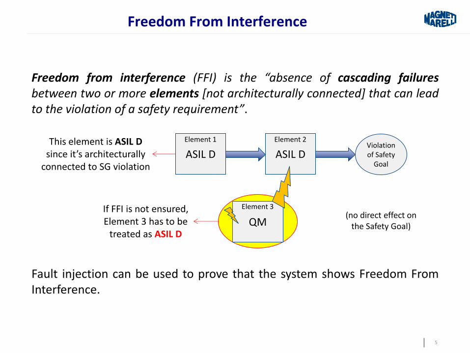
Freedom from interference (FFI) is the “absence of cascading failures between two or more elements [not architecturally connected] that can lead to the violation of a safety requirement”.
Fault injection can be used to prove that the system shows Freedom From Interference.
Freedom From Interference
5
QM
ASIL D
Element 3
Element 2
If FFI is not ensured, Element 3 has to be
treated as ASIL D
Violation of Safety
Goal ASIL D
Element 1 This element is ASIL D since it’s architecturally
connected to SG violation
(no direct effect on the Safety Goal)
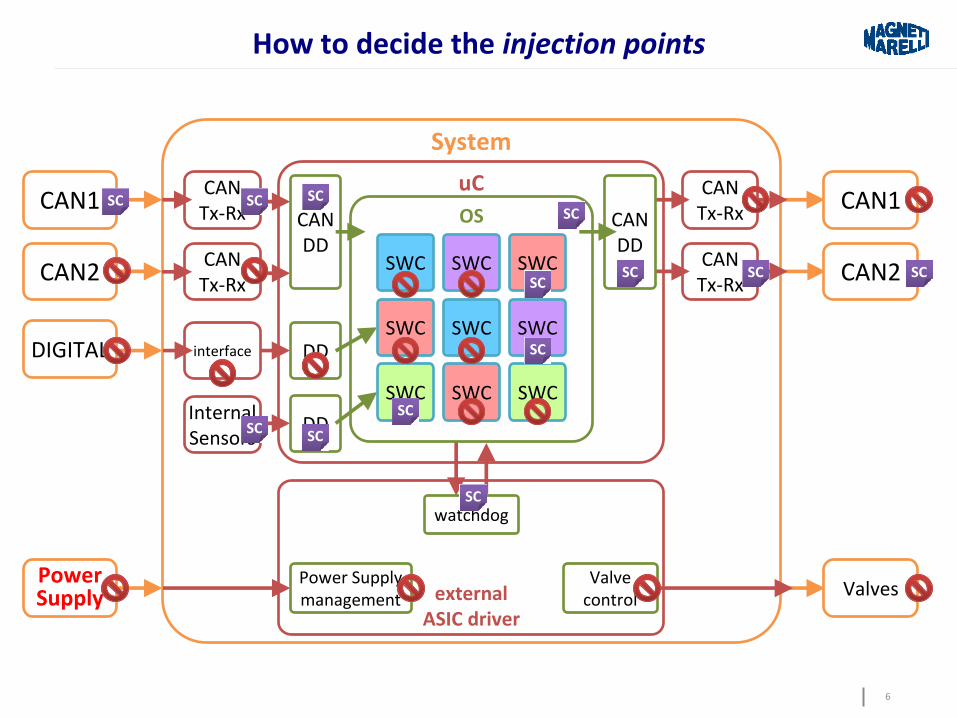
How to decide the injection points
System
CAN1
CAN2
DIGITAL
CAN1
CAN2
Valves Power Supply
CAN Tx-Rx
CAN Tx-Rx
CAN Tx-Rx
CAN Tx-Rx
uC
interface
external ASIC driver
Internal Sensors
CAN DD
CAN DD
DD
OS
DD
Power Supply management
watchdog
Valve control
SWC
SWC
SWC
SWC
SWC
SWC SWC SWC
SWC
SC SC SC
SC SC
SC
SC
SC
SC
SC SC
SC
SC
6
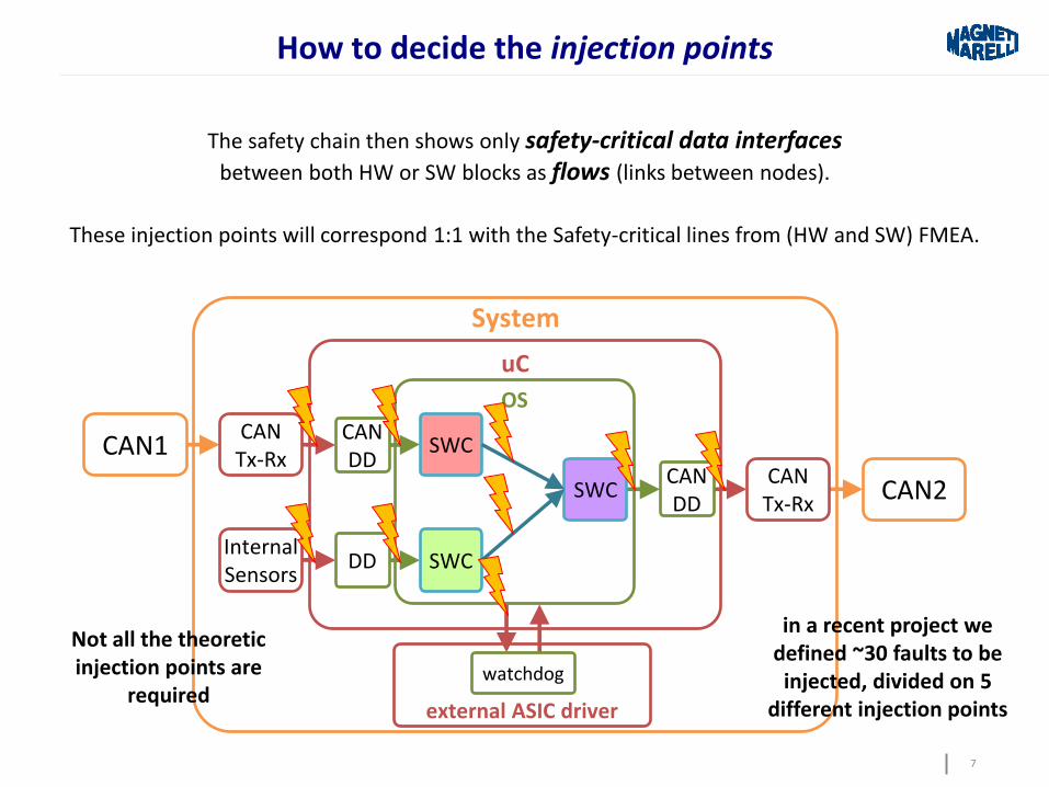
How to decide the injection points
The safety chain then shows only safety-critical data interfaces between both HW or SW blocks as flows (links between nodes).
These injection points will correspond 1:1 with the Safety-critical lines from (HW and SW) FMEA.
System
CAN1
CAN2 CAN Tx-Rx
CAN Tx-Rx
uC
external ASIC driver
Internal Sensors
CAN DD
OS
DD
watchdog
SWC
SWC
SWC CAN DD
7
in a recent project we defined ~30 faults to be injected, divided on 5
different injection points
Not all the theoretic injection points are
required
Software-based Fault Injection
8
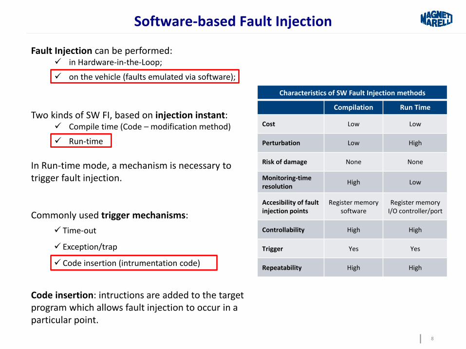
Characteristics of SW Fault Injection methods
Compilation Run Time
Cost Low Low
Perturbation Low High
Risk of damage None None
Monitoring-time resolution
High Low
Accesibility of fault injection points
Register memory software
Register memory I/O controller/port
Controllability High High
Trigger Yes Yes
Repeatability High High
Fault Injection can be performed: in Hardware-in-the-Loop;
on the vehicle (faults emulated via software);
Two kinds of SW FI, based on injection instant:
Compile time (Code – modification method)
Run-time
In Run-time mode, a mechanism is necessary to trigger fault injection. Commonly used trigger mechanisms:
Time-out
Exception/trap
Code insertion (intrumentation code)
Code insertion: intructions are added to the target program which allows fault injection to occur in a particular point.
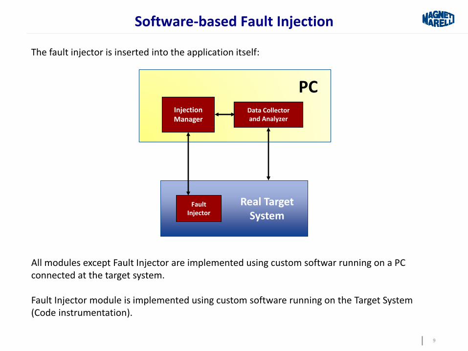
All modules except Fault Injector are implemented using custom softwar running on a PC connected at the target system. Fault Injector module is implemented using custom software running on the Target System (Code instrumentation).
The fault injector is inserted into the application itself:
Injection Manager
Data Collector and Analyzer
Fault Injector
Real Target System
PC
Software-based Fault Injection
9
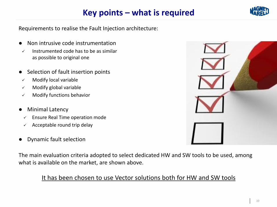
Requirements to realise the Fault Injection architecture: ● Non intrusive code instrumentation
Instrumented code has to be as similar as possible to original one
● Selection of fault insertion points
Modify local variable
Modify global variable
Modify functions behavior
● Minimal Latency
Ensure Real Time operation mode
Acceptable round trip delay
● Dynamic fault selection
The main evaluation criteria adopted to select dedicated HW and SW tools to be used, among what is available on the market, are shown above.
It has been chosen to use Vector solutions both for HW and SW tools
Key points – what is required
10
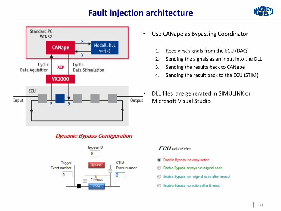
• Use CANape as Bypassing Coordinator
Fault injection architecture
11
1. Receiving signals from the ECU (DAQ)
2. Sending the signals as an input into the DLL
3. Sending the results back to CANape
4. Sending the result back to the ECU (STIM)
• DLL files are generated in SIMULINK or Microsoft Visual Studio

• Additional features and macros to be included in the ECU code Code instrumented following Vector requirements
• Global variables acquired and modified
A2L file to be managed
• Execution of function’s dynamic bypasses
Possibility to execute ECU code or DLL code
• Real time operation is demostrated Studying Round Trip Delay with PC or dedicated HW
Using two twin ECUs on the same vehicle
• Automatic selection of fault injection trigger
Critical point for vehicle dynamic or particular proving ground section
Particular state of ECU input/output
• Manual selection of fault injection trigger Physical start button available for user
Key points – what has been achieved
12
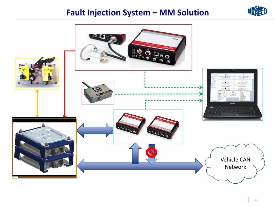
CAN Gateway
PC Data Logger
+ Fault Injection
tool
Vehicle CAN Network
Fault Injection Specific HW
Dummy Sensors & Actuators
GPS
ECU REF
ECU DUT
Fault Injection System – MM Solution
13

• NORMAL OPERATION ECU output is computed and then
sent on CAN network every 10 ms
• FAULT INJECTED A bypass substitutes the value
computed by ECU algorithm with a fixed one before sending it on CAN
• EXPECTED BEHAVIOR ECU signal on CAN is different from
the value computed by the algorithm
ECU REF output [Nm]
ECU DUT output [Nm]
Fault Injection Instant
Focus on
Fault Injection Instant
Results – Fault on CAN output
14
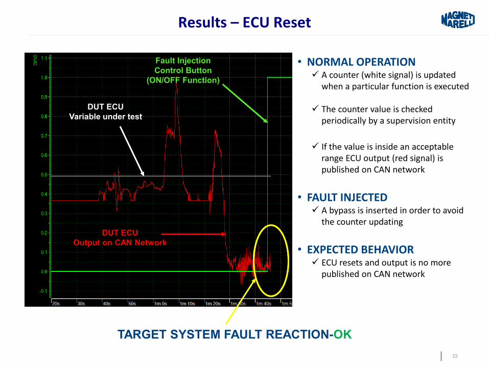
Fault Injection
Control Button
(ON/OFF Function)
DUT ECU
Output on CAN Network
DUT ECU
Variable under test
• NORMAL OPERATION A counter (white signal) is updated
when a particular function is executed The counter value is checked
periodically by a supervision entity
If the value is inside an acceptable
range ECU output (red signal) is published on CAN network
• FAULT INJECTED
A bypass is inserted in order to avoid the counter updating
• EXPECTED BEHAVIOR
ECU resets and output is no more published on CAN network
TARGET SYSTEM FAULT REACTION-OK
15
Results – ECU Reset

16
Conclusions
The defined Fault Injection methodology allows system validation in compliance with ISO 26262, Part 4, Clause 9;
Test pattern definition follows a valid procedure that can validate any element of a system, including HW, FW, SW and Operating Systems;
The MM Fault injection system is effective in implementing Test Patterns, and to check safety mechanisms against timing constraints like the Fault Tolerant Time Interval;
The Fault injection can be conducted on vehicle without exposing the driver to harm, thanks to the “Twin ECUs” structure;
All the described methodology can be applied to any Safety-relevant project.
The Fault injection has also been performed without “Twin ECUs”, on the ECU directly connected to the Vehicle Network, to test driver controllability.
CTO - EECC
Fulvio Tagliabò
Thanks for the attention
For further information please write to
Marco Ferrato
Fabrizio Tronci Gaetano Fiaccola