safe cooperating cyber-physical systems using wireless ... · safe cooperating cyber-physical...
TRANSCRIPT

Safe Cooperating Cyber-Physical Systems using Wireless Communication
Report type Deliverable D3.1
Report name State-of-the-Art on Communication Protocols
Dissemination level PU [CO, PU, CI]
Report status: [First, Draft]
Version number: 1.0
Date of preparation: 2017.03.31
Ref. Ares(2017)1758112 - 02/04/2017

D3.1 JU GA# 692529
© The SafeCOP Consortium 2
Report type Deliverable D3.1
Report name State-of-the-art on Communication Protocols
Dissemination level PU
Report status: Final
Version number: 1.0
Date of preparation: 2017.03.31
Contributors
Instituto Superior de Engenharia do Porto, ISEP, Portugal (leader)
Qamcom Research & Technology AB, QAMCOM, Sweden
GMVIS SKYSOFT SA, GMV, Portugal
Stiftelsen SINTEF, SINTEF, Norway
Università degli Studi di L'Aquila, UNIVAQ, Italy
RO technology S.r.l., ROT, Italy
Finnish Meteorological Institute, FMI, Finland
Mobisoft Oy, MOBISOFT, Finland
Mälardalen University, MDH, Sweden
SICS Västerås AB, SICS, Sweden
DNV GL AS, DNVGL, Norway
Intecs S.p.a., INT, Italy
Technical University of Denmark, DTU, Denmark
Maritime Robotics AS, MARO, Norway
Odense Universitetshospital, OUH, Denmark
D3.1 JU GA# 692529
© The SafeCOP Consortium 3
Revision history
0.1 First draft
0.5 Preparation for submission
1.0 Final

D3.1 JU GA# 692529
© The SafeCOP Consortium 4
1 Table of Contents
1 INTRODUCTION 7
1.1 CONTEXT AND OBJECTIVES 7
1.2 OVERVIEW OF CO-CPS 7
1.3 GENERAL REQUIREMENTS ON WIRELESS COMMUNICATIONS FOR CO-CPS 8
1.3.1 DEPENDABILITY 9
1.3.2 SECURITY 17
1.3.3 PERFORMANCE ASPECTS 25
1.3.3.1 TIMELINESS 25
1.3.3.2 SCALABILITY 27
1.3.3.3 HETEROGENEITY 29
1.4 PARTICULAR REQUIREMENTS OF SAFECOP’S APPLICATION DOMAINS 31
1.4.1 HEALTHCARE APPLICATION DOMAIN 31
1.4.2 MARITIME APPLICATION DOMAIN 35
1.4.3 AUTOMOTIVE APPLICATION DOMAIN 37
2 OVERVIEW OF WIRELESS STANDARDS 44
2.1 WWAN/WMAN PROTOCOLS 44
2.1.1 GPRS 45
2.1.2 3G/4G 45
2.1.3 5G 48
2.2 WLAN 54
2.2.1 IEEE 802.11 B/G/N 54
2.2.2 IEEE 802.11P 56
2.2.3 NEXT GENERATION HAM RADIO PROTOCOL (DNV GL, [email protected], MARO) 61
2.3 WPAN 63
2.3.1 IEEE 802.15.4 63
2.3.2 ZIGBEE 65
2.3.3 6LOWPAN 67
2.3.4 RPL 69
2.3.5 LORAWAN 71
2.3.6 INDUSTRIAL WPAN 74
3 DISCUSSION 86
DESIGN METHODOLOGY 87
3.1 WIRELESS REQUIREMENTS FOR USE CASES 88
3.1.1 USE CASE 1 – COOPERATIVE MOVING OF HOSPITAL BEDS 88
3.1.2 USE CASE 2 – COOPERATIVE BATHYMETRY WITH AUTONOMOUS BOAT PLATOONS 91
3.1.3 USE CASE 3 – VEHICLE CONTROL LOSS WARNING 92

D3.1 JU GA# 692529
© The SafeCOP Consortium 5
3.1.4 USE CASE 4 – VEHICLES AND ROADSIDE UNITS INTERACTION 96
3.1.5 USE CASE 5 – V2I COOPERATION FOR TRAFFIC MANAGEMENT 96
3.1.6 USE CASE 6 – 5G V2X COOPERATIVE COMMUNICATIONS 97
FUTURE RESEARCH DIRECTIONS 98
USE CASE 1 – COOPERATIVE MOVING OF HOSPITAL BEDS 98
USE CASE 2 – COOPERATIVE BATHYMETRY WITH AUTONOMOUS BOAT PLATOONS 100
MARITIME REGULATIONS - IMO REQUIREMENT RELATED TO COMMUNICATION (SHIP-SHIP/SHIP-SHORE) 100
USE CASE 3 – VEHICLE CONTROL LOSS WARNING 100
USE CASE: COOPERATIVE MOBILE ROBOTS 101
3.2 USE CASE: 5G COOPERATIVE SHORT DISTANCE GROUPING (COSDG) USE CASE 101
USE CASE 6 – GENERIC PRINCIPLES: PLATOONING 102
SICS AND MDH CONTRIBUTIONS 102
4 REFERENCES 103
APPENDIX 113
5G 113
THE METIS2020 PROJECT 113
CHANNEL MODEL 115
5G AND 802.11P 115
802.11P 116
IEEE 802.15.4 125
PHYSICAL LAYER 126
MAC LAYER 127
TOPOLOGY 129
ZIGBEE 130
PHYSICAL LAYER AND MAC LAYER 130
NETWORK LAYER (NWK) 130
APPLICATION LAYER 131
TOPOLOGY 132
PERFORMANCES 134
SCALABILITY 139
6LOWPAN 140
NETWORK TOPOLOGY 140
SOFTWARE 141
NETWORK LAYER 141
ADAPTATIVE LAYER 144
TRANSPORT LAYER 146
RPL 147
UPWARD ROUTING 148
DOWNWARD ROUTING 152

D3.1 JU GA# 692529
© The SafeCOP Consortium 6
INTERACTION RPL – 6LOWPAN 155
LORAWAN 156
IEEE 802.15.4E 160

D3.1 JU GA# 692529
© The SafeCOP Consortium 7
1 Introduction
1.1 Context and Objectives
The objective of this deliverable is threefold: first, to carry out a thorough report of the wireless
communication technologies potentially interesting for general CO-CPS; second, to evaluate the adequacy of
these communication standards to the different Use Case (UC) scenarios, by reviewing their appropriateness
in terms of a set of properties, such as timeliness, safety, among others; and finally, to propose extensions
and mechanisms that may solve the identified shortcomings for the target application scenarios. Proposed
future research directions are to be followed in task T3.2 of WP3 and instantiated in the target UCs.
Importantly, several general requirements per UC have been already identified in a previous deliverable
(D1.1). This document extracts the ones mostly concern the wireless perspective and presents real solutions
to support the desired Quality of Service levels in each UC.
1.2 Overview of CO-CPS Modern embedded systems, coupled with advancements in wireless technologies have been enabling a new
generation of systems, tightly interacting with the physical environment via sensing and actuating actions [].
These Cyber Physical Systems (CPS), are characterized by an ever-increasing and unprecedented level of
pervasiveness and ubiquity, relying upon wireless communication technologies to provide seamless services.
Cooperating CPS are systems of systems that collaborate for a common purpose. In this line, Cooperating
Cyber-Physical Systems (CO-CPS) are expected to base important decisions on data gathered from external
sensors and use external actuators to enforce safety critical actions.
These systems however, must be conceived in a way that the Quality of Service (QoS) recognized by their
users (e.g. directly humans or other information systems) is above an acceptable threshold. Traditionally,
QoS is associated with metrics such as bit rate, network throughput, message end-to-end delay and bit error
rate. Nevertheless, these properties alone do not reflect the overall quality of the service provided to the
user/application. According to each application/task requirement, which can be rather diverse [],
computations and communications must be correct, secure, produced before a given deadline and with the
smallest energy consumption. To attain the desired pervasiveness, these systems are expected to be highly
heterogeneous and cost-effective, maintainable and scalable.
Therefore, considering all these aspects, QoS in these systems must be looked at from a holistic perspective,
as a mix of different system quality properties that must be fulfilled to different levels, depending on the
particularities of each application scenario. This all-inclusive definition of QoS takes special importance if we
notice that many of these topics are complex, if not impossible to address together, since some might be
conflicting. For instance, improving timeliness might decrease energy-efficiency. The same applies to
improving scalability, which might impact timeliness due to the introduction of routing delays in the network.
Therefore, considering all of these QoS is quite a complex issue in wireless communications, especially
when additional requirements such as dependability and security come into play. In the next sections we

D3.1 JU GA# 692529
© The SafeCOP Consortium 8
provide a strategy to address the top requirements in SafeCOP, and how these can be integrated in a more
general perspective, to reach an adequate QoS level for each use case in SafeCOP.
1.3 General Requirements on Wireless Communications for Co-CPS
SafeCOP targets safety-related Cooperating Cyber-Physical Systems (CO-CPS) characterized by use of wireless
communication, multiple stakeholders, dynamic system definitions (openness), and unpredictable operating
environments. In this scenario, no single stakeholder has the overall responsibility over the resulted system-
of-systems; safe cooperation relies on the wireless communication; and security is an important concern.
Therefore, it is clear that in these target scenarios dependability and security, are among the top concerns.
Hence, to adequately target such application areas, we must consider a new aspect which traditionally has
been neglected in wireless communications research, i.e. how to efficiently address Dependability and
Security.
We define Dependability as the ability to provide services that can defensibly be trusted within a time-period
[Kumar2015]. This is, from a system’s perspective, a measure of its reliability, maintainability, integrity,
availability and safety.
In addition to Dependability, Security must also be addressed. Security is a composite of the attributes of
confidentiality, integrity, and availability, requiring the concurrent existence of 1) availability for authorized
actions only, 2) confidentiality, and 3) integrity with “improper” meaning “unauthorized.”[Avizienis2004]
Hence, we are now looking towards a tridimensional system of requirements that must be fulfilled to
adequately support safety-related systems with wireless communications (see Figure 1.1). In the first axis we
find the traditional QoS properties that concern the performance of the system, such as timeliness or energy-
efficiency, in the second and third axes we find Dependability and Security.
Figure 1.1. System requirements dimensions
The challenge in these systems in terms of communications is to find the best set of coordinates, i.e. the best
QoS balance, in this tri-dimensional system. Again, on the one hand, considering Dependability alone will

D3.1 JU GA# 692529
© The SafeCOP Consortium 9
probably result in a safe but overall non-functional or extremely limited system. For instance, the use of
redundant communications might impact the performance requirements. The same applies to Security, since
having a secure system does not provide any guarantee in terms of Performance and can sometimes be in
opposition with it due to heavier resource requirements, causing for instance a highly inefficient system in
terms of energy. Considering performance attributes alone, on the other hand, does not provide the
necessary guarantees in terms of functional safety or security to address the kind of systems we are targeting.
Hence, a tradeoff between these different attributes must be reached.
1.3.1 Dependability
We aim at bringing CO-CPS into a set of applications that have been traditionally relying on wired
infrastructures due to the immatureness of wireless technologies in respect to some of the mentioned
attributes. These systems, which fall under the denomination of safety-related systems, are required to
perform a specific safety function or functions to ensure that the risk of failure of a system is at a minimum
or at an accepted level. In such systems, failures and errors lead to hazardous situations, e.g. environmental
damage, injury, or death.
Despite significant progress in proving reliability and robustness to wireless infrastructures these were not
designed with functional safety in mind, thus although several mechanisms are available for improved
reliability in these networks, there is no actual acknowledged standard for wireless communications in safety-
related systems. Nevertheless, applying digital communications to a safety-related system is not new and
has been done since the 1980s via safe bus communications. The principles for the development of safety-
related systems treated in the IEC 61508 are directly applicable for the development of wireless control
systems. The same applies to other standards.
The Safety Life cycle proposed in IEC 61508, or a reduced version of it, should be followed as much as possible
to design a wireless, safe system.
The standard IEC 62061, for instance provides requirements and recommendations to carry out a successful
hazard and risk analysis, containing elements of risk estimation, risk evaluation and risk reduction option
analysis. The primary purpose of hazard analysis is to classify hazards and/or hazardous situations for
appropriate further treatment. It acts as a screening technique reducing the number of specific risks, which
have to undergo the full process of risk estimation. This standard can be applied to the development of a
system with safety concerns, considering wireless communications a small part of it.
Regarding risk estimation and evaluation, for each hazard and activity identified, the risk should be assessed
according to the severity of the hazard, and its probability, as a function of the frequency and duration of the
exposure to the hazard, the probability of occurrence of a hazardous event, and the technical and human
possibilities to avoid or limit the consequences.
Errors are also identified and a number of aspects is considered for each, such as actions to decrease the risk
of harm, and eventual consequences. Such an analysis eventually generates new requirements to be fulfilled
by the system. These will usually be more or less demanding, according to the chosen system SIL level.

D3.1 JU GA# 692529
© The SafeCOP Consortium 10
Figure 1.2. Dependability Diagram
The IEC 61508 standard defines a System Integrity Levels (SIL) from SIL 1 up to SIL 4 (Figure 1.3). The highest
the more severe the requirements, and thus usually more complex and expensive the system becomes. In
addition, the standard also specifies two modes of operation, low demand, or high demand.
Figure 1.3. System Integrity Levels
High demand mode (continuous mode) is used in production engineering, where continuous monitoring of
the working process of the system is required with PFH (Probability of Failure per Hour) values shown to
determine the SIL levels. Low demand mode is used in process industry, where it is required only when the

D3.1 JU GA# 692529
© The SafeCOP Consortium 11
process of the system is out of control (e.g. Emergency Shut Down (ESD) systems) with Probability of Failure
on Demand (PFD) values shown to determine the SIL levels [IEC 61508] , [Siemens AG].
Wireless Communication Risks
While there are a number of advantages in using wireless systems, its higher availability and dependency of
radio communications raises a number of threats that must be addressed.
In [Timo Malm] the authors carry out a risk assessment of general wireless communications. We start by
overviewing a set of threats and their consequences regarding wireless communications.
Basic threats Consequences
The transmission fades because the distance between sender and receiver increases
Signal level is low. Bit error rate increases. Data is corrupted or lost.
The signal fades because of obstacles Signal level is low. Bit error rate increases. Data is corrupted or lost.
Transmission signal fades because of environment conditions
Signal level is low. Bit error rate increases. Data is corrupted or lost.
Transmission signals are reflected from surfaces resulting in echoes and interference, or signal appears because of reflections from long distances
Signal level is low. Bit error rate increases. Data is corrupted or lost. Inserted new messages.
Two or more signals interfere with each other and cause proper signal for another receiver
Bit error rate is high and therefore an acceptable transient signal can be initiated.
Receiver is too sensitive. Signal is generated out from noise. Short message can appear.
Poor capability of a relaying station. The signal can be delayed e.g. due to heavy traffic or extra signal processing in relaying stations.
The nodes understand the network state or configuration differently at the same time.
Consistency and stability problems especially when nodes are moving. Radio B can hear radio C and A, but radio A cannot hear radio C. This may cause confusion
Nearby wireless network is using similar communication protocol.
One node is substituted intentionally or unintentionally with another node
Security; intentional penetration to New messages may be inserted

D3.1 JU GA# 692529
© The SafeCOP Consortium 12
wireless network
Systematic failure, characteristics of wireless communication is not considered
Almost any of the above mentioned consequences may result
Sleeping nodes in low power networks. Some nodes can be ordered to sleep to lower power consumption i.e. longer battery life.
There is no communication through a sleeping node until the node awakes.
These threats can be further classified into four groups of basic threats:
Hardware and software systematic failures - examples: incorrect network dimensioning, small
memory capacity, antenna misalignment;
Hardware permanent stochastic failures - examples: Open or short circuits;
Transient and intermittent failures - examples: interference, environmental disturbances;
Unauthorized modification of messages - examples: malicious attack, rogue nodes.
All these threats potentially lead to transmission failures that can be further classified as:
Repetition - A message is sent repeatedly. Transmitter is unable to send new information or the rate
of information overflows the communication media, disabling any other communications.
Deletion - Transmission media is disturbed in a way that makes it impossible to receive a message.
Also, detected message corruption will usually lead to deletion.
Insertion - A message is received unintentionally, usually because the additional message presents a
valid address.
Incorrect Sequence - Messages are received in incorrect order. There can be several causes, such as
multiple paths.
Message Corruption - The data present in a message is changed, usually due to electromagnetic
interference.
Delay - A message gets received correctly but with a significant delay that hinders the validity of the
message content.
Erroneous Addressing (Masquerading) - This can be caused by a misrouting of a correct message or
by an unauthorized message.
Facing these errors, a safe wireless communication system must be protected against them, considering one
more communication failures can potentially lead to a system fault. Hence, a set of defensive mechanisms

D3.1 JU GA# 692529
© The SafeCOP Consortium 13
against basic, message and system threats must be in place. In what follows, a set of defences against these
threats is enumerated as an example.
Defensive Mechanisms
Defensive mechanisms against basic threats
Basic Threat Defence
Systematic Failure Improved and aided design methods by network planning tools or simulation; Improved safety requirement specification.
Stochastic Failure Use of reliable components, redundancy, overvoltage and overcurrent protection; Use of environmental shielding; Improved preventive maintenance.
Transient and Intermittent Failures Usage of interference free radio frequencies; Signal to noise ratio monitoring; Usage of adequate and reliable communication rates; Electromagnetic shielding; Monitoring of transmission latency in regards to a worst-case response time;
Unauthorized Modification Encryption schemes and error correcting coding; Security enforcing by preventing physical tampering with the system; Restricting physical access (prevents only system unauthorized modification). Software checksums;
Defensive Mechanisms against message threats
Dealing with message threats is fundamental to ensuring safety in wireless communications. Standards such
as the IEC 61508 specify that at least one defensive mechanism against each threat must be in place. In the
following table we show examples of defensive mechanisms against general wireless message threats. In
order for a communication system to be considered safe, at least one defence mechanism against each error
must be supported.
Repetition Deletion Insertion Incorrect sequence
Message Corruption
Delay Masquerading
Sequence number Effective Effective Effective Effective Some Effect

D3.1 JU GA# 692529
© The SafeCOP Consortium 14
Time stamp Effective Effective Effective Effective
Time out Effective
Safety coding Effective Effective
Acknowledgement messaging
Effective Effective Some Effect
Effective Effective Effective
Membership control
Effective
Sender/receiver Id Effective
Replication Some Effect
Some Effect
Some Effect
Some Effect
Time triggered Effective Effective Effective Effective Effective
Traffic differentiation
Some Effect
Encryption Some Effect Effective
Alternating Messaging
Effective Effective Effective Effective Effective
Hamming distance in message parts
Effective Some Effect
Redundancy with cross comparison
Effective Effective Effective Effective
Certain type of defensive method can be effective or poor depending on the chosen effectiveness. Here are
observations of some defensive methods:
● Safety code - The most simple safety code is parity bit it can detect all single bit errors and 50 % of
random messages. It is not sufficient to be used for safety purposes as the only method. Cyclic
redundancy checks (CRC) can detect usually all few bit errors (depending on CRC code and message
length) and probability not to detect random message bit error is for 16 bit CRC 2 -16. In safety-
related communication usually 32 bit CRC or checksum is used. Feedback messages. Feedback
messages may contain many kind of information at it affects the effectiveness of the method. If
feedback message contains time stamp the transmitter will know when it was received and delays
are revealed. If the feedback message contains safety code, the transmitter can calculate if the
message were correctly received.
D3.1 JU GA# 692529
© The SafeCOP Consortium 15
● Message replication - Message can be repeated in order to be sure that the message was correctly
received. The method is often quite slow since the entire message is repeated. Yet, if the same bit is
incorrect in both messages, the information is incorrect.
● Alternating messages - It is possible to convert some or all of the bits in a message. This will reveal
missing or extra message. It is also possible to pick up acceptable messages from a predefined table.
It makes possible to ensure also the integrity of the message, because only certain data is acceptable.
This method is used when the messages are very short.
● Hamming distance in message parts - Hamming distance in message parts means that only certain
predefined identifiers, address codes and messages are allowed. If e.g. one or two bits change in the
message an acceptable message will not appear.
● Timing information - The message may contain time stamp or sequence number, which shows when
the message was sent. If the timestamp is short (e.g. one bit), also the probability of an undetected
error increases. The timing information can also mean simply utilization of the receivers clock
(nothing in the message). If no acceptable messages are received during certain period of time an
error handling sequence is started.
Redundancy with cross comparison [EN 50159-2] - This method tests the redundant data transmission for
correctness in order to overcome retransmission, loss, insertion and wrong sequence errors.
More about the methods are described in “Methods for Verification & Validation of time-triggered
embedded systems” [Hedberg, J].
Defensive Mechanisms against system threats
Not all threats can be avoided completely, nor every error detected, thus implementing defences at the
system level is always a good option. Three defences are hereby proposed in what follows:
Defence Details
Redundancy Parts of the communication system are made redundant, such as different transmission frequencies.
Monitoring The correct functioning behaviour of the system is monitored using Runtime Verification.
Resilience The hardware and software components of the system are designed via a systematic approach
All these safety methods which target basic, message and system threats should be implemented for safety
related systems in a way that it is sufficient to achieve the required SIL levels. As a reference, some wired
Safe Communication Examples
Although fieldbus protocols are widely used for transmitting the data in the factory floor, data is typically not
safe. An independent and separate safety layer is necessary to detect the link connection or device failures

D3.1 JU GA# 692529
© The SafeCOP Consortium 16
and to implement the necessary actions such as an emergency shutdown in order to avoid dangerous
situations. This layer must be able to detect and provide protection against the transmission errors and
erasures, and at least one safety method as presented in previous tables has to be implemented as a defence
against each error. This approach is called “Black Channel” concept, in which an additional safety protocol is
developed with the independent safety methods. This concept has already been developed in railway
industry for communication, signalling and processing systems and the same concept is also implemented by
a number of safety related Field-bus technologies [Piggin, R].
PROFIsafe
Profisafe is designed using the “Black Channel” concept. The additional safety protocol layer is developed on
the top of the Field-bus application layer to reduce the transmission errors and erasures, thereby reducing
the residual error probability. PROFIsafe supports a safety integrity level of SIL3 by relying on this concept.
The implemented safety methods are independent to the error detection and correction methods
implemented at the lower layers of the standard Profibus protocol communication channel.
PROFIsafe protocol mechanisms are based on Finite State Machine (FSM), thus it was possible via a validation
tool for finite state machines to prove mathematically [PROFIsafe] that PROFIsafe works correctly even in
situations where more than two independent errors or failures may occur. Safety certification process of this
protocol is followed according to the standard IEC 61508.
SafetyBUS p
SafetyBUS p was launched in 1999, and it is the most widespread safety related industrial network in use
today. It is based on CAN (Controller Area Network developed by the company Bosch), which is widely utilised
networking technology for agricultural, automotive, embedded machine control, marine, military, rail and
industrial applications. Kuka Roboter GmbH developed a safety system for industrial robots via a safety
related Field-bus i.e. SafetyBUS p, in cooperation with Pilz GmbH. The Electronic Safety Circuit (ESC) coupled
with SafetyBUS p and Pilz Programmable Safety System (PSS) safety controllers are being used by the
company BMW, to achieve a more flexible safety approach for robot processes. It is suitable for use in safety
systems up to EN 954-1 Category 4 and safety integrity level SIL3 applications according to the standard IEC
61508 [Piggin, R].
INTERBUS-Safety
INTERBUS-Safety is a functional extension of INTERBUS system for the transmission of safety related data. As
PROFIsafe, it is also based on the “Black Channel” concept to ensure safe data transmission. The INTERBUS-
Safety system meets the safety functions up to category 4 according to EN 954 and safety integrity level SIL3
according to the standard IEC 61508.
Safe Ethernet
Safe Ethernet [Handermann, F] offers open communication and safe transmission of data via Ethernet,
independently of the transmission medium. To protect data transmission, Safe Ethernet implements at the

D3.1 JU GA# 692529
© The SafeCOP Consortium 17
application of layer 4 (transport layer), protocols with an additional CRC. An example to achieve this is to use
the reliable UDP (RUDP) transport layer protocol that uses IP and combines the advantages of TCP and UDP.
Similar to PROFIsafe, the header of RUDP consists of a sequence number, an acknowledgment, and a CRC in
order to achieve higher error detection capabilities [Handermann, F]. Safe Ethernet is certified in accordance
with the standard IEC 61508 and the protocol achieves a safety integrity level up to SIL3. Both, the safe and
non-safe data are transmitted in parallel to have dual operation with the non-safety related systems existing
on the same network without any restriction.
Concerning wireless, currently, wireless communication technologies are not frequently used for safety
related systems, due to their higher Bit Error Rate (BER) and loss of information. However, there have been
a few works that address these issues such as in [Pendli, 2012], where the author analyses the Bluetooth
wireless technology and extends it for safety related systems to achieve safe communication. Also, in [Ikram,
2013] a SIL 2 gas detection system was developed relying upon the ISA100.11a and PROFISafe using a black-
channel approach.
1.3.2 Security
Safety and security are both very important issues of the overall system dependability, but there are many
subtle interactions and interdependencies among safety, performance and security as introduced in 1.3
“General Requirements on Wireless Communications for Co-CPS”.
In general, security is conflicting with safety and performances, thus requiring to evaluate a quantifiable
trade-offs between the three. In addition, resource constraints may make it infeasible to guarantee
absolute security in all circumstances. The introduction of security requirements into systems tends to
modify the priorities of some other non-functional requirements.
As an example, the authentication and authorisation mechanisms might meet critical real time
requirements in “most” cases, but not always, making it impossible to certify and use the system in a safety
critical environment. Conversely, QoS constraints placed on systems by safety functions could preclude
implementation of adequate security mechanisms.
One of the key issue that allow the trade-offs evaluation is the definition of a metric. Metrics are also
suitable for security assessment of services, applications, as well as user and network nodes.
Standards are not yet consolidated; the most significant work is the one presented by the Center for
Internet Security [CIS2010], but is far to be complete and widely applicable. At the moment, CIS identified
and modelled six business functions that are: Incident Management, Vulnerability Management, Patch
Management, Configuration Management, Change Management, and Application Management. For each
function, the relevant metrics are organised into three hierarchical categories:
Management Metrics that provide information on the performance of business functions, and the
impact on the organization,
Operational Metrics, used to understand and optimize the activities of business functions,
Technical Metrics that provide technical details as well as a foundation for other metrics

D3.1 JU GA# 692529
© The SafeCOP Consortium 18
The work presents, using a relational model, a list of information and attributes that complete the
identification and definition of the metrics, with the indication of possible values, or ranges, each attribute
can assume and the relevant dependencies and relations between different metrics.
The Network Information Security Platform WG3 provided the “State-of-the-Art of secure ICT landscape”
[Kert2014] proposing a complete study of the security strategies, tools and researches, in the context of the
EU Strategy for Cyber Security.
The NIS study span from access control, system integrity, cryptology, audit and monitoring, to hardware,
software, network and mobile security. Then it extends the evaluation to different domain application class
like Clouds and IoT, as well as the transport and mobile communication cases.
Business model evolution The security approach has been focused on the trustiness of the information flowing through the network,
creating security protection mechanism that mainly enforce the network access and utilisation (e.g. user
authentication, message integrity, etc...).
The evolutionary scenario is characterised by: the increasing number of interconnected devices; the IoT and
Big Data analytics; the expansion of virtualisation both for processing (clouds) and networks (SDN, NFV); the
network's heterogeneity integrating a wide type of communication channels and relevant protocols either
for access and transport networks.
These scenarios require a significant improvement of security solutions to manage: the infrastructure; a
multi-vendor environment; differentiated service requirements; isolation of (group of) resources and (group
of) users; mobility and dynamic reallocation of nodes (e.g. BYOD concept); D2D connections, generally
implying latency and throughput constraints (e.g. V2V use cases and LTE proximity service); user privacy.
As a general issue, it is necessary to take in care, in addition to the trustiness of the network nodes, also the
trustiness of users and services nodes, extending the authentication mechanisms, as simplified in the
following Figure 1.4.
Figure 1.4. Authentication mechanisms

D3.1 JU GA# 692529
© The SafeCOP Consortium 19
For the applications and services, security-by-design is a basic concept that needs to be exploit, adopting
strategies, like the ones defined in Multiple Independent Levels of Security (MILS) architecture [Blasum2014],
to assure and to assess the security objectives. Security-as-a-service is another approach that should be used
in a virtual environment following the “anything-as-a-service” principle.
Flexibility and scalability are additional properties that security solutions must meet, specifically in the case
of Co-CPS, where different systems could participate to a cooperative group with different roles and the
group dimension can vary over time, like in vehicular use cases, where a platoon is a high dynamic set of cars
continuously entering and exiting the platoon itself. Vision and details on these items are available in
[Horn2015], [Huawei2015] and [Ericsson2015].
Integrated security approach The presented evolutions and the highlighted challenges must be faced using new paradigms that need to address the security issues globally (i.e. the whole system must be designed to be secure). Three basic steps are recognised, to allow a system to contrast an attack:
Sense: is the ability of a system to predict and detect security threats, before the attack is successful.
Audit, monitoring and data analytics should allow a system to gain early warning of a risk.
Resist: is the ability of a system to contrast any attack with defence countermeasures. This ability is
usually limited by the current knowledge of possible threats.
React: when both sense and resist strategies fail, the system needs to deal with the possible
disruption. The incident must be manages to avoid or limit damages and to collect as much data are
possible to support the breach investigation and learning how to improve resilience.
Some basic actions the previous steps require to be implemented are:
Risk Assessment and Management: allows to mitigate the potential impact of security vulnerabilities
developing protective measures. It consists of: identifying, categorizing, prioritizing, and treating
security risks that could lead to safety and data loss.
Security by Design: enables efficient design and development of reliable systems. It involves the
integration of hardware and software security features during the product development process.
Threat Detection and Protection: Proactive security through the detection of threats, vulnerabilities,
and incidents. Threat detection processes raise awareness of suspicious activity, enabling proactive
remediation and recovery activities.
Incident Response and Recovery: Document how a security threat has been contrasted and witch
recovery actions has been taken for continuous process improvement.
Security for UC domains
Risk assessment Taking in care the proposed use cases, the risk assessment should provide different conclusions for maritime
and health UCs versus automotive UCs.
D3.1 JU GA# 692529
© The SafeCOP Consortium 20
Both maritime and health UCs are built around a “closed” environment, i.e. the cooperating nodes can be
identified at mission configuration time and do not change during the whole mission delivery, simplifying
access controls. The service provided and the communications between nodes can also be “pre-planned”
and follow some predefined schema. Therefore, the isolation concept identified in MILS can be enforced,
limiting the interaction of Co-CPS nodes with the external world. The security cannot be guaranteed 100%
(e.g. radio jamming can result in a DoS) but the risk can be controlled and managed.
At the opposite, the vehicular UCs expose a completely different situation:
the set of nodes participating to a platoon can constantly vary during time
authentication should be completed under severe latency constraint to avoid safety impact, thus
limiting the possibility of strong verifications
communication can be based on heterogeneous networks using different protocols
different services, may be from different service providers, other than the ones related to the specific
Co-CPS vehicular domain, should be active on a participating nodes, exposing the whole system to a
wide variety of attacks
there is no guarantee that a node entering a platooning is not “infected” and there should not be a
priori the possibility to verify the presence of the infection
etc...
In addition, several works demonstrated that, vehicular control systems are far to be intrinsically secure
[Koscher2010] [Miller2015]. In this case the security issues must be carefully evaluated to ensure the security
of the infrastructure and the services and to enforce the protection of the vehicle control system.
Security by design This item represent the major concern of the WP2 research activity, see the relevant deliveries
Threat Detection and incident report
These topics are summarized in the following section that provide a brief summary of the current approach
Security topics The following table summarises the processes to be addressed to secure the network access and communications:
Security process Description
Authentication,
Authorization and Access
control
Access control allows to determine via specific policies the assignment of
distinct roles to different types of nodes/services and their allowed
actions within the system. Authorization establishes what each node is
allowed to do in the network, for example, which types of messages it
can insert in the network, or, more generally, the protocols it is allowed
to execute. The authentication should guarantee the trustiness of the
participating nodes.

D3.1 JU GA# 692529
© The SafeCOP Consortium 21
Accountability The ability to map security related events to system entities and network
nodes
Message authentication
and integrity
Protection against any alteration of the messages exchanged, allowing
the receiver of a message to have evidence of the aliveness and
trustiness of the sender.
Message non-repudiation The sender of a message cannot deny having sent a message
Message confidentiality It keeps the content of a message secret from those nodes not
authorized to access it
Privacy protection It safeguards private information of users. This is a general requirement
that relates to the protection of private information stored offline.
Mainly relevant for automotive use cases where a vehicle or a driver
cannot be tracked
Cryptography
Cryptography is used in mostly all of the security processes listed above as it is the base mechanism used to secure information and communications in a system. According to the distribution of keys in the network, there will have three types of cryptosystem:
● Symmetric: it uses the same key both for encryption and for decryption of data (e.g. AES);
● Asymmetric: the encryption key is different from the decryption key (e.g. RSA);
● Hybrid: it uses the asymmetric model to distribute the symmetric keys, eventually also generated by
a single party or by the parties involved in the scheme. The advantage of hybrid schemes is the ability
to use encryption and decryption algorithms less complex computationally, like appropriate and
desirable in applications in the domain of WSN networks.
Typically symmetric algorithms are characterized by excellent computational performance but have the
problem of having to absolutely protect the key in the exchange phase, because if it was discovered anyone
could reconstruct the plaintext message.
As mentioned above, asymmetric algorithms use different keys for encryption and decryption, taking
advantage of the properties of so-called one-way functions. For the one-way functions the inversion
algorithm is typically of non-polynomial complexity, and then it can be assumed that an attacker cannot
reconstruct the key (and thus the message) in a time comparable with the mean life of the data transmission
session. In mathematical terms, placing K’ as the private key and K as the public key, it is achieved:
K=f(k’), where f() one-way function, extremely complex compute K’ from K.
So it is possible to make public a key, taking advantage of the difficulty to derive the private key. Therefore
you can use the public key of the recipient of a message for the encryption operation, because it can be
assumed that only the recipient knows his own private key to decode the message. The encrypted messages

D3.1 JU GA# 692529
© The SafeCOP Consortium 22
with a given public key can be decrypted only by the person that has the corresponding private key, and this
guarantees confidentiality. The figure below shows a typical example about encryption and decryption
operations (Figure 1.5):
Figure 1.5. Procedures of Encryption and Decryption of messages in asymmetric encryption
In these schemes, it must however take into account that for disclosing the public key typically uses a
Certification Authority (CA), introduced in order to distribute and certify the authenticity of public keys of the
nodes.
Finally, the hybrid cryptography combines symmetrical and asymmetrical schemes to get benefits from both
approaches. A hybrid algorithm typically uses asymmetric cryptography to establish in a cryptographically
secure way a symmetric key between the parties, and then switch to a symmetrical pattern where it will be
used the key you just exchanged for encryption and decryption the message. For this reason, the key is also
called session key, and the hybrid encryption schemes are also called Key Transport Schemes.
Access control
Access control process for Co-CPS should take in care several scenarios where different strategies should be adopted to address several constraints like real-time, privacy, system performance, etc...
The basic: mandatory, discretionary and role-based access control models have been reviewed to take in care privacy and performance issues.
The “attribute-based” and “credential-based” solutions making use of “credentials”, released and certified
by a certification authority. The credential is used to determine the properties, instead of the identity, of the
subject demanding access, i.e. the holder, not necessarily the owner, of the certificate.
A step ahead is based on “pseudonym” solution. A pseudonym, in theory, should guaranteeing the property
of unlinkability to its holder and other pseudonyms used by the same holder. In practice, pseudonymity
provides a compromise between full anonymity and accountability. A user employing a pseudonym engages
in communications and transactions without revealing his identity, but third parties or the holder himself will
provide the linkability for accountability. Giving a user has its own asymmetric private and public key pair, a
pseudonymous certificate, issued by a trusted provider, binds a user's pseudonym to his public key.
Pseudonym must be unique and can be, either centralised or locally generated:

D3.1 JU GA# 692529
© The SafeCOP Consortium 23
● centralised generation allows to create a unique pseudonym issued by a third party that know the linking between the pseudonym and the holder identity;
● locally generated (private) pseudonym are created by the holder himself not propagating linking information, a central authority take in care to associate the private pseudonym to a globally public unique pseudonym.
Access control become critical in high dynamic wireless network environment like in V2V and V2I use cases,
where a significant number of nodes should enter or exits a platoon continuously. Strategies should be
adopted to comply with privacy, performances and functional safety requirements as well as connection
availability that are strictly constraining the interaction with central authorities releasing certificates.
A security credential management system for vehicle-to-vehicle communications has been presented in
[Whyte2016], developed under a Cooperative Agreement with the US Department of Transportation. Privacy
is achieved issuing pseudonym certificates provisioned among multiple organizations, creating a mechanism
to facilitate efficient revocation.
To address the drawback that the centralised management of certificates and pseudonym imply,
[Huang2016] proposed a solution based on Software Defined Network infrastructure defining a hierarchical
structure of central, local and vehicular clouds that share and manage the pseudonyms distributions.
Message Integrity
One of the key issues in sharing information is to guarantee that it is not corrupted when received. That is, it
is necessary to certify the trustiness of the information source (i.e. using digital signature) and to prove the
information content has not changed at the receiving side (i.e. using message authentication code).
The Digital Signature process of a message is equal to encrypt it with the private key of the sender and the
verification process is equivalent to decipher it with the sender's public key. The recipient of a message will
instead be implicitly authenticated by the Certification Authority that provides guarantees of authenticity of
public keys. The figure below shows the Procedure of Digital Signature in the asymmetric scheme:
Figure 1.6 The procedure of Digital Signature in the asymmetric scheme
Integrity checks ensure that the contents of the transmitted messages is not altered during transmission, or
intentionally by malicious nodes or accidentally due to environmental conditions. Support to the integrity is
offered by Message Authentication Codes (MAC), through which it is possible to detect any abnormalities.

D3.1 JU GA# 692529
© The SafeCOP Consortium 24
The functions to compute MAC are hashing functions of the message, such as SHA algorithm used in
combination with a cryptographic key, as in the case of the AES-CMAC-x family functions.
Security threats
The main threats are classified as in the following table:
threat description
Rogue Access Points
and Trusted Third Party
Consist in setting up a rogue access point that is within the range of the
existing wireless LAN, fooling some of the legitimate devices into
associating to this access point over the legitimate ones. Similarly, at
application level, a “trusted” service can be emulated to mistakenly give
information or data (e.g. duplicate SSL certificates as the WoSign Chinese
certificate authority did in the past) able to exploit systems weakness.
Denial of Service It consist in sending a large amount of traffic to a specific target with the aim of saturating communication resources. While DoS or DDoS affect the whole network and system integrity, it should be security related if used to support the Rogue Access Point attack eventually mixed with a Passive Capturing strategy.
Misconfiguration Errors in configuring a transmission device should create potential
vulnerabilities.
Passive capturing Consist in listening and capturing data that can be used for a number of
things including attempting to break existing security settings and
analysing non-secured traffic. Man in the Middle attack is an example of
such kind of attack used both for capturing and tampering data.
Defensive mechanism
The basis of any defence mechanism is the concept of “isolation” as used in MILS architecture: any
node/service, in a secure environment, is isolated from the other nodes; the communications are allowed
and constrained, through secured channels, only through a predefined set of nodes using predefined
protocols.
The following list classify the main defence support currently available:
Environment Protection
Hardware and Operating
platform
Security protection starts from securing the platform over which the
services and applications run. Basically, this is a matter to adopt a secure-
by-design approach, guaranteeing that the platform itself do not expose

D3.1 JU GA# 692529
© The SafeCOP Consortium 25
vulnerability and, vice-versa, it support the MILS architecture, data
protection, secure software updates, etc..
Services and
applications
Anti-viruses is the main defence against malware that should affect
applications installed on a system.
Gateways The interfaces connecting to the external world requires additional
securing mechanism. Firewalls are the means to control the external
interfaces access, the external nodes allowed to communicate and the
protocols to be used; thus, enforcing the domain isolation principle. The
firewalls have also the ability to log and map security related events to
system entities and network nodes
Interfaces Interfaces are the gates through which the attacks are performed and
intrusions can occur. The main protection mechanism make use of strong
encryption and authentication to ensure that the communication is
between trusted entities only and that received data can be trusted as
well.
Network Additional protection against any alteration of the messages exchanged,
can be performed, at different protocol layers, by inspection of message
content. In-deep inspection and intrusion detection allow for detecting
anomalies in the network traffic, see [Marchesani2013].
1.3.3 Performance Aspects
1.3.3.1 Timeliness
The ubiquity and pervasiveness of Cooperating CPS systems will lead to a very tight integration and
interaction between embedded computing devices and the physical environment, via sensing and actuating
actions [J. Stankovic]. Given that the computing entities closely interact with their environment, timeliness is
of increasing importance, which demands a rethinking in the usual computing and networking concepts [A.
Stankovic].
The “timeliness” non-functional property concerns the timing behaviour of a system, including issues such as
network throughput (effective bit rate) and transmission delay.
Some CO-CPS applications, or some specific tasks within an application, might also impose to be finished
within a certain time limit (deadline). In this case, we usually refer to these as “real-time” applications/tasks,
encompassing the need for real-time computation (requiring real-time operating systems and programming
languages) and real-time communications (requiring real-time communication protocols). For instance, in a
CO-CPS there might be a task that is to process a certain event (e.g. gas leak) in a certain region and transmit
that information to a remote sink within 10 seconds (at the latest). Note that the timing behaviour or

D3.1 JU GA# 692529
© The SafeCOP Consortium 26
Cooperating Object hardware, such as sensors/actuators, signal conditioning circuits and analogue-to-digital
converters, must also be considered due to its impact in monitoring/control loops.
Usually, two classes are distinguished, namely hard real-time applications and soft real-time applications.
Hard (or strict) real-time means that missing a deadline leads to a critical or catastrophic failure in the
application domain; hence, temporal constraints must be strictly respected to ensure the reliable operation
of the application. Examples of hard real-time application are the ABS car braking system or the control of a
manufacturing robot. Soft real-time means that the application can survive or tolerate missing some
deadlines, just leading to a “quality degradation”; a typical example would be multimedia streaming over a
network. A soft real-time system tries to minimize the deadline miss ratio, or to provide a probabilistic
guarantee on the deadline miss ratio.
The general principle of real-time systems design is to ensure temporal predictability of the tasks involved in
the application, and in their scheduling. Hard real-time systems require a strict worst-case execution time
(WCET) analysis of the tasks (and the related worst-case transmission times for the communication aspect),
while soft real-time systems can use statistical analysis based on code profiling, simulation or real
experiments.
A fundamental difficulty in designing CO-CPS systems with real-time requirements results from design
principles that are usually antagonist to “traditional” real-time systems. “Traditional” real-time systems
require over-allocation of resources (resulting from the inherent pessimism of the analysis, e.g. WCET),
usually reducing their adequateness to tackle the dynamic behaviour of the physical phenomena. On the
other hand, these systems, which rely mostly on unattended resource-constrained WSN nodes, try to
optimize resource usage, and also depend heavily (by definition) on the dynamic nature of their environment.
An example is tracking the motion and evolution of a fluid (e.g. gas leak), where the computational and
communication demands change in time and space, according to the propagation of that fluid.
As already mentioned, NFPs are usually interdependent. This also applies to timeliness, meaning that, for
instance, to increase network throughput we might opt for increasing the “hardware” bit rate or increasing
the WSN nodes’ duty cycle, which both lead to higher energy consumption. Real-time issues have only
recently drawn attention from the Cooperating Objects and Wireless Sensor Network scientific community.
However, the real-time behaviour of Cooperating Object systems will be of increasing importance for many
applications: real world processes and phenomena often require real-time data acquisition and processing.
Some examples include mission critical applications, such as early warning systems for natural disasters or
contamination (forest fires, earthquakes, tsunamis, radiation, etc.) or support for emergency interventions
(firemen, etc.). Real-time constraints may be even more stringent in applications such factory automation,
health case, ambient assisted living or intelligent transportation systems. In this context, it is crucial that
WdSN resources are predicted in advance, to support the prospective applications with a predefined
timeliness. Thus, it is of paramount importance to have adequate methodologies to dimension network
resources in such a way that the system behaves as expected [A. Stankovic]. However, the provision of
timeliness guarantees has always been considered as very challenging due to the usually severe limitations
of WSN nodes, such as the ones related to their energy, computational and communication capabilities, in

D3.1 JU GA# 692529
© The SafeCOP Consortium 27
addition to the large-scale nature of WSNs. So, adequate mechanisms must be devised for dimensioning WSN
resources so that to guarantee a minimum timeliness performance.
Actually, the evaluation of the performance limits of WSNs is a crucial task, particularly when the network is
expected to operate under worst-case conditions [Zhihua Hu]. For achieving real-time communications over
sensor networks, it is mandatory to rely on deterministic routing and MAC (Medium Access Control)
protocols. Usually, these networks use hierarchical network / topological models such as hexagonal, grid or
cluster-tree (e.g. [Tarek Abdelzaher], [J. Gibson], [P. Jurcik]). Basically, these network models rely on (1) the
use of contention-free MAC protocols (e.g. (I) Time Division Multiple Access (TDMA) or (ii) token passing or
(iii) strictly prioritized MAC protocols and unique priorities [N. Pereira]) to ensure collision-free and
predictable access to the medium, and (2) the ability to perform end-to-end resource reservation. These
represent important advantages of hierarchical topologies when compared to what can be achieved in flat
mesh-like topologies, where contention-based MAC protocols and probabilistic routing protocols are
commonly used, preventing them from providing a deterministic performance (timing and buffer).
There are also mechanisms that try to address timeliness in a more relaxed perspective (i.e. soft real-time).
These proposals usually try to improve the opportunity for message transmission by establishing different
traffic priorities at the MAC layer or in case of time division based MACs, by changing the transmission
schedule to minimize the delay. Regarding traffic differentiation strategies, these usually rely on a priority
toning approach or on the tuning of a set of MAC layer attributes.
Priority toning is used to signal the transmission of a higher priority frames [Tae Hyun], [Tae Hyun Kim],
[Joseph Jeon]. The toning mechanism imposes some changes to the hardware (using a tone signal
transmitter), and this represents a major drawback for these proposals. Other approaches that do not
present such an inconvenient have been proposed in the literature to support service differentiation. These
are usually similar to the strategy implemented in the IEEE 802.11e Hybrid Coordination Function (HCF) by
defining variable parameters such as Arbitrary Interframe Space (AIFS), CWmin and CWmax. This strategy
has been successfully extended to other protocols in [R. Severino], [A. Koubaa],[D. Kipnis]. Other proposals
also address the network layer and focusing on clustered network topologies for instance, proposals such as
[R. Severino] adopt a cross-layer approach, to improve several QoS aspects, namely timeliness.
1.3.3.2 Scalability
A CO-CPS may involve different entities, such as network nodes (for serving as sensors/actuators, routers/
gateways and/or sinks/controllers), machines (e.g. roller belt, mobile robot, fridge, traffic light) or living
beings (plants, animals, humans, bacteria). Depending on characteristics such as the application, the
environment or the users, a CO-CPS scale may dynamically change with time. The term “scale” applies to the
number (fewer or more nodes in the overall system), spatial density (fewer or more nodes in a restricted
region), or geographical region under coverage (smaller or wider, 2D or 3D). The ability of such system to
easily/transparently adapt itself to these dynamic changes in scale is named “scalability”.
Consider an application used for early detection of forest fire which is implemented in a huge forest such as
the Amazons. Depending on the sensing information granularity (more sensor density leads to richer
information, but also to more information to transmit and process) that is required and to the very limited

D3.1 JU GA# 692529
© The SafeCOP Consortium 28
transmission range of WSN nodes (few meters), the network may scale up to thousands nodes in order to
cover the whole area. In such a case, the algorithms running inside the network should scale well in parallel
to the increasing number of nodes in a region, still guaranteeing that the application behaves correctly.
Additionally, the system should adapt itself to these scale changes in a transparent way, i.e. without requiring
user intervention.
Note that while it might be straightforward that scalability is an important issue for “outdoor” applications,
“indoor” applications such as factory automation, security and domotics might also impose a high level of
scalability to the underlying system.
While some ongoing efforts envisage to effectively build WSNs with hundreds/thousands of sensing nodes
(e.g. VigilNet, [T. He]), the ExScal project (Elements of an Extreme Scale Wireless Sensor Network, [A. Arora])
engineered the largest Wireless Sensor Network test-bed so far. A 1000+ node Wireless Sensor Network and
a 200+ node peer-to-peer ad hoc network of 802.11 devices were deployed in a 1.3 km by 300 m remote
area in Florida (USA), late 2004.
Although a very large number of processors and sensors can operate in parallel and hence the processing
and sensing capabilities increase linearly with the number of sensor nodes, the communication capability
does unfortunately not increase linearly with the number of sensor nodes. Consider for example 1 million
WSN nodes densely deployed in a small area. Two nodes sending simultaneously would cause a collision and
hence it is necessary that at most one node sends at a time. With typical WSN nodes today, it takes at least
1 ms to send a message, and hence it takes at least 1000 seconds (approximately 20 minutes) for all nodes
to send their data. In dynamic environments subject to rapid changes with time (which is typically the case
in CO-CPS), this might be unacceptable, or at least undesirable. It is also unacceptable from an energy-
efficiency perspective because all nodes need to be “awake” for all these 20 minutes just to compute an
aggregated quantity (say minimum temperature) from the sensor readings.
Therefore, it is of particular importance that the communication protocol (or protocols) serving as the
networking infrastructure are designed with scalability in mind. For instance, Medium Access Control (MAC)
and routing mechanisms must encompass scalability, otherwise problems such as uncontrolled medium
access/routing delays or routing tables’ buffer overflows may occur. Scalability must also be taken into
consideration for achieving efficient data processing, aggregation, storage and querying in CO-CPS, especially
when large amounts of data are involved. Advancements on wireless dominance-based MAC protocols (like
the one used in the Controller Area Network) provide unprecedented advantages for Wireless Sensor
Networks, namely because aggregate computations can be performed with a complexity that is independent
of the number of sensing nodes [B. Andersson]. Currently the approach is capable of (i) computing the
maximum of sensor readings on all sensing nodes, (ii) computing the minimum of sensor readings on all
sensor nodes, (iii) obtaining an interpolation as an approximate representation of all sensor readings, (iv)
obtaining an estimate of the number of sensing nodes and (v) iteratively search for a hypothesis that is
compatible with the sensor readings that the majority of sensor nodes had.
One strategy towards a better support of network scalability relies on the use of hierarchical (or tiered)
network architectures. Several research works and commercial products propose hierarchical architectural

D3.1 JU GA# 692529
© The SafeCOP Consortium 29
solutions for Wireless Sensor Networks, namely for enabling Internet to get into the “smart objects” level.
The concept of multiple-tiered network architectures has been employed since a long time ago in other
networking domains (e.g. Switched Ethernet over field-bus networks in industrial environments or Internet
(IP) running over different lower level protocols - ATM over Switched Ethernet).
In [Venkata A. Kottapalli] the authors proposed the use of a two-tiered WSN architecture for structural
health monitoring. This is a GSM-like architecture that divides the monitored area into several clusters.
Each cluster is managed by a local master that handles the communication using a TDMA-like protocol
inside the cluster. This approach lacks scalability inside each cluster due to the TDMA inherent limitations.
Also, this architecture is entirely dependent on the presence of a local master to ensure communications,
which is not suitable for WSNs. In fact, for a large-scale network, this architecture is unpractical since the
number of local master’s increases linearly with the number of deployed nodes, resulting in a significant
increase of the overall cost.
It was proposed in [Omprakash Gnawali] to use a gateway as a portal where every Wireless Sensor Network
node is identified by an IP address, allowing direct and individual access. However, there is no mobility
support and the handling of very large networks may become a difficult task. In [Anis Koubaa] and [J. Leal]
propose a multiple-tiered architecture relying on an IEEE 802.11/WiFi-based backbone and an IEEE
802.15.4/ZigBee-based sensor/actuator network. Though there is a concern on supporting QoS in IEEE
802.15.4/ZigBee-based Wireless Sensor Networks, especially on supporting both best-effort and real-time
traffic, there are still lots of open issues to be solved, especially at the backbone network level.
Some commercial solutions rely on IP/Ethernet for their backbone network. These approaches might be
cost effective and reliable for small and static networks but the scalability for the higher tier (IP/Ethernet) is
limited by the need of a physical Ethernet port for every gateway. Additionally, other QoS features (such as
timeliness) are basically neglected.
1.3.3.3 Heterogeneity
CPSs are usually based on very complicated infrastructure of heterogeneous entities that interact with each
other. They tightly couple computation, communication, and control along with physical dynamics, which are
traditionally considered separately. A multitude of models exists for model-based development of CPSs in a
variety of formalisms that capture various aspects of the system design, such as software design, networking
design, physical models, and protocol design.
A multi-view unifying architecture framework was proposed in [Rajhans2014] that treats models as views of
the underlying system structure and uses structural and semantic mappings to ensure consistency and enable
system-level verification in a hierarchical and compositional manner.
Being CPSs heterogeneous in nature, their interoperability is a serious challenge. Accessing these
heterogeneous systems from the Internet is not straightforward without having standard and common
interfaces. To overcome this issue, there is a need to virtualize their resources and expose them as services
to facilitate their integration.
D3.1 JU GA# 692529
© The SafeCOP Consortium 30
In addition, as sensors are used in different areas and applications, they are sources of heterogeneous and
diverse types of collected data, which can be either structured, such as temperature and pressure, or
unstructured such as images, videos and audios. This results in the concept of big data that provides new
opportunities, yet challenges, in what concerns processing and analysis to extract useful information. Indeed,
WSNs provide useful big data that can be analysed and processed to serve human life in several areas.
There are different classifications of data heterogeneity types. In [Jirkovsky 2016], the following types of
heterogeneity are proposed:
● Syntactic heterogeneity — occurs when two data sources are not described in the same knowledge
representation formalism (e.g., F-logic and OWL in the case of integration of ontologies).
● Terminological heterogeneity — means variations in names when referring to the same entity (e.g.,
different natural language).
● Semantic heterogeneity — occurs when different models are used for the same domain of interest
(e.g., utilization of different axioms for defining concepts).
● Semiotic heterogeneity — denotes different interpretation of entities by different people. Let us
point out that usually several heterogeneity types occur together.
The main causes of the semantic heterogeneity among data-sources can be identified as different designer
influences in the developing processes. In other words, a design autonomy includes the following conflicts:
● Difference in coverage — occurs when data-source models describe different data regions (possible
overlapping) at the same level of detail and from the same perspective.
● Difference in perspective — occurs when data-source models describe the same data regions at the
same level of detail, but from different perspective.
● Difference in granularity — occurs when data-source models describe the same data regions from
the same perspective, but at different level of detail.
● Incompatible design specifications — occurs when different specifications of schema are used.
Heterogeneity reduction of CPSs is introduced as a promising solution in [Jirkovsky 2016], by means of shared
ontology which is demonstrated on the Semantic Big Data Historian. The overall contribution of the paper
includes the clarification of the semantic heterogeneity reduction process and facilitation of process usage
within a real application.
CPSs are typically integrated into a more complex system for an improvement of their capabilities. Every
system maintains specific data model, which is derived from the nature of corresponding physical process or
processes. CPSs provide data via an interface to other CPSs or other systems. Reversely, it consumes data
from surrounding systems for an enhancement of physical process control. Furthermore, CPSs can share joint
data storage — local/distributed/in cloud. The integration problem can be divided into two distinct
problems corresponding to various perspectives:
1) Low-level integration — interconnections among components of a CPS. The CPS consists of a physical part
and a cyber part. The physical part involves the physical process and physical objects, which provide
possibility for process controlling. The cyber part can be divided for clarity into two layers — the first layer

D3.1 JU GA# 692529
© The SafeCOP Consortium 31
(Platform Layer) represents a system integration of different devices from various manufacturers and the
second layer (Computational Layer) represents the computational process, which is able to control the
physical process according to an implemented logic. In other words, the physical process is modelled first
with a physical layer abstraction. Then, the corresponding control system is implemented using a
computational (software) layer abstraction. Finally, the control system is deployed on the computation
platform modelled with the platform layer abstraction. The different abstraction layers use typically non-
compatible semantics, which is the cause of semantic heterogeneity.
2) High-level integration — interconnections of various CPSs to form for example IoT.
Nowadays, a common integration of system components relies on ad hoc solutions. These solutions can
provide very effective systems. However, they may bring many drawbacks — difficult system maintenance,
malfunction corrections, adding or adjusting components, re-usability, etc. This approach solves a platform
heterogeneity but does not provide any information about a data meaning.
The integration task consists in the unification of CPS interfaces as well as the unification of corresponding
data models. This integration becomes more difficult in the case of increasing complexity of systems. CPSs
integration process should address two dimensions:
1) System integration — the first step of CPSs integration lies in the platform unification because of different
interfaces provided by various manufacturers.
2) Model integration and semantic integration — model integration covers the identification of
corresponding concepts, relations among concepts and their meaning in given context.
For any system to be widely adopted, there is a crucial requirement to adopt standards to promote
interoperability among heterogeneous systems and provide universal solutions that are vendor-independent
and platform-agnostic. The current status of cyber-physical clearly shows that most of the solutions are
proprietary although some of them rely on open-source platforms [Yoo2016]. However, universal
agreements on networking protocols, data exchange formats, interfaces, etc., are not yet achieved. In other
words, it is important to unify for each technology a set of standard protocols that govern the interaction
between cyber-physical systems, Machine-to-Machine and also their interaction with clients and end-users,
as well as the storage and processing processes, and network interfaces. Several new opportunities for CPSs
raise with the emergence of cloud computing and the Internet- of-Things (IoT), taking advantage of the cloud
resources in different ways. In the survey paper [Chaaria2016], an overview of research efforts on the
integration of cyber-physical systems with cloud computing is proposed, focusing on three major CPSs
namely mobile robots, wireless sensor networks and vehicular networks, which are largely related to SafeCOP
UCs.
1.4 Particular requirements of SafeCOP’s application domains
1.4.1 Healthcare Application Domain

D3.1 JU GA# 692529
© The SafeCOP Consortium 32
System overview
The system consists of the following modules and the diagram below shows the required connections and
interfaces between them.
• 2 Mobile robots
• 2 Modular Link Controllers controlling the high level functionality of the robots
• Scalable number of surveillance modules to assess whether or not an area is safe to enter for the
robots
• Possible external systems that are already in place at the UC area and could provide useful
information.
The 2 mobile robots and controllers will be responsible for synchronizing and coordinating their movement
so they can move the empty hospital bed from point to point without colliding with anything. However, the
on-board sensors of the robot cannot cover the entire robot-bed-robot convoy at all times and external
sensors are needed at areas with poor visibility and tricky geometry in order to ensure safety.
Therefore, surveillance modules will be created that can monitor an area for obstacles and human activity
and indicate to people in the area if the robot convoy is coming. The robots will connect wirelessly to the
surveillance modules and use the information to make decisions on how to proceed into the area covered
by the surveillance module – e.g. slow down due the presence of people or obstacles, park at the nearest
parking spot due to an emergency etc.
Communication
The following communication directions have been identified, but requirements and chosen technologies
might differ for each and have not yet been established/chosen. Points marked with [-] indicate that the
communication link does not exist in a satisfactory manner and input from WPs are needed to choose the
right technology and implementation.
MLC to mobile robot
• Wired Ethernet connection already in place.
• [-] Currently no redundancy if the communication link should fail
This communication channel is wired and currently works satisfactorily. However, it must be investigated if
there needs to be a redundancy in the communication link and if it makes sense to have redundant
communication channels without total hardware and software redundancy on both ends of the
communication link.
MLC to MLC

D3.1 JU GA# 692529
© The SafeCOP Consortium 33
• [-] Real time wireless communication required between the two MLCs on the two robots.
Currently both MLCs connect to the same standard WiFi network and communicate through that. This is
sufficient for task that are not time-critical, but for safely coordinating and synchronizing the movement of
the two mobile robots we need some guaranteed delivery times, latency etc. It is also important to detect if
the communication channel suffers from performance degradation since the robots must take precautions
or stop if the communication is too poor.
[-] MLC to surveillance modules
• Wireless connection between the MLC and surveillance modules.
• Connection to multiple surveillance modules at the same time must be possible.
• Pseudo redundancy if both MLCs connect to the same module and compare the received data
before making a decision.
• The amount of data transmitted is currently thought to be the 4-bits result of the video
surveillance modules. In this way it is sufficient with low bandwidth and low security but there is
still a need for low latency.
Since these surveillance modules are still at a very early idea stage, it is not possible to know the exact
requirements of the communication between the robots and the surveillance modules. However, it must
be possible for the robots to connect to multiple modules and the communication should have error-
detection so faulty information does not get transmitted.
[-] MLC to external systems
Wireless connection to any external system in place at the use case area that could provide useful
information to the robot systems, or that the robot systems can report its own situation to. Likely a
standard WiFi network.
Sec. 1.4.1.3 Requirements
Here are listed and briefly described all the communication requirements that apply to the UC1:
1. Connection establishment delay: Connection establishment delay between nodes must be limited. This
delay has to be under a specific threshold, determined according to applications constraints. Moreover, it
could be useful to distinguish between connection and reconnection establishment delay.
2. Real time communication: Guaranteed latency / delivery time in communication between two nodes.
Also in this case the applications using the wireless channel determine the maximum acceptable latency.
3. Physical link and communication quality: The quality of the link has to be adequate to support the correct
delivery of the messages. The communication quality is an analogue metric, but referred to a higher level in
the nodes protocol stack. Obviously such parameters are tightly correlated to each other. There are several

D3.1 JU GA# 692529
© The SafeCOP Consortium 34
possible metrics to evaluate these qualities, such as for example Received Signal Strength Indication (RSSI),
Signal-to-Interference-plus-Noise Ratio (SINR), Packet Delivery Ratio (PDR), Packet Loss Rate (PLR) and Bit
Error Rate (BER).
4. Detect degradation of link and/or communication quality: Detect degraded physical channel and/or
communication quality so the nodes can take the appropriate actions to face possible missing information
due to poor communication. Obviously it is necessary to detect the degradation as soon as it happens.
Possible metrics are the ratio of correct detection and the delay in the detection, which have to be
respectively maximized and minimized.
5. Communication loss: The unexpected interruption of the communication between two nodes can have
extremely negative impact in the safety assurance. It has to be properly faced, even adopting a certain level
of redundancy in the communication. Possible evaluation metrics for the wireless channel are the number
of communication losses in a certain period and the duration of such losses. Both parameters needs to be
minimized.
6. Detection of communication loss: As for the quality degradation also in case of communication loss is
crucial to detect as soon as it happens. To evaluate the efficiency of the detection mechanism it is possible
to consider the detection rate and the delay in this operation as metrics.
7. Multiple connections / scalability: The nodes must be able to establish and maintain multiple
connections at the same time. The total number of nodes supported by the network, the number of nodes
connected to a single nodes and the number of nodes simultaneously transmitting on the channel are
important characteristics of the wireless network.
8. Communication range: The maximum supported distance between two communicating nodes must be
adequate according to specific applicative scenario. In particular the importance of this requirement
increases when the nodes speed increases. As a matter of fact, the higher is the speed the larger has to be
the communication range to assure to the receiving node a sufficient time to receive the information and
to take the appropriate actions (consider the automotive use case as a significant example).
9. Data security and encryption: Data exchange between nodes must be properly secured due to security
and/or privacy laws and to prevent unauthorized access and alteration of the message content for
malicious purposes.
Communication requirements ID Category Priority
Physical link and communication quality
UC1004 Reliability; Communication;
H
Detect degradation of link and/or communication quality

D3.1 JU GA# 692529
© The SafeCOP Consortium 35
Communication loss
Detection of communication loss
Connection establishment delay UC1007 Timeliness; Communication
M
Real time communication UC1005 Timeliness; Communication
H/M
Data security and encryption UC1009 Security; Communication
M
Multiple connections/scalability UC1010 Scalability; Communication
H
Communication range UC1008 Communication M
1.4.2 Maritime Application Domain
Unmanned Surface Vehicle (USV) system is a risk eliminating and cost saving tool for maritime data
acquisition in the surface zone. The potential applications of such system include geophysical exploration
and environmental monitoring with its long-range capability of acquiring data automatically in a 24/7
operational time-frame.
UC2 defines an application of cooperative bathymetry with a platoon of USVs. For both operation scenarios
considered in UC2, the USV(s) are continuously monitored and/or operated by the operator via Vehicle
Control Station (VCS). The USV(s) regularly transmit the data (e.g. measurement, control messages, etc.) to
the manned vessel. To fulfil both safety and mission requirements, the communication between the USV(s)
and the manned vessel has to be highly reliable and available. Therefore, there are some requirements
which shall be fulfilled when implementing the communication scheme for UC2.
1. Detection of communication loss
Both the manned vessel and USV(s) shall be able to detect loss of communication between the manned
vessel and the USV. Depending on the operational mode of the USV, the time limit of detecting
communication loss may be different.
2. Redundant communication channel
To ensure reliable communication, a redundant communication channel shall be available in case the
communication channel being used is lost.
3. Detection of communication degradation

D3.1 JU GA# 692529
© The SafeCOP Consortium 36
Wireless communication faces the big challenge of signal degradation. The signal strength may impact the
transmission errors accordingly. The connected vessels shall be able to detect degradation of
communication and have the mitigation functionality.
4. Timeliness for different applications/type of traffic
The same channel may be used for transmitting different applications of traffic and control messages. It is
necessary that the timeliness of each type/application of traffic can be fulfilled.
5. Detection of data loss
During data transmission, a packet loss can occur. The probability of packet loss in wireless communication
is even higher due to the error-prone nature of wireless channel. So it is crucial for reliable communication
to provide feedback and acknowledgement scheme to detect packet loss.
6. Communication range
The distance between two communication nodes can significantly impact the signal strength which closely
decides the quality of the communication. Therefore, it is important to appropriately select physical
parameters of the wireless channel to fulfil the data transmission requirements.
7. Security
It is well known that wireless communication is prone to some security issues. To reduce the security risks,
security measures have to be implemented to reduce exploitable weakness and attacks, such as
authentication, authorization, encryption, etc.
8. Data integrity
Packet corruption is another common issue during wireless communication. Integrity of the data
transmitted between the manned vessel and USV(s) has to be assured by employing error detection and
correction schemes.
9. Scalability
As more USVs are connected to the manned vessel, the overall performance will be impacted, such as
packet delay, throughput, packet loss, etc.
Communication requirements
Requirement ID Category Priority
Detection of
communication loss
There is no corresponding requirement ID. But the implementation of UC2 has this functionality.
Dependability H
Redundant
communication channel
There is no corresponding requirement ID. But the implementation of UC2 has this functionality.
Dependability H

D3.1 JU GA# 692529
© The SafeCOP Consortium 37
Detection of
communication
degradation
There is no corresponding requirement ID. But the implementation of UC2 has this functionality.
Dependability M
Timeliness UC2012: Message timeliness Dependability Security Performance
H
Detection of data loss There is no corresponding requirement. Dependability Security
H
Communication range There is no corresponding requirement. Dependability Performance
M
Security UC2010: Message authenticity UC2013: Message sequence
Security H
Data integrity UC2011: Message integrity Dependability Security
H
Scalability There is no corresponding requirement. Performance M
1.4.3 Automotive Application Domain
1.4.3.1 Vehicle Control Loss
Control Loss Warning (CLW) systems are designed to detect and alert about control loss situations. A CLW
system has the ability to monitor system’s status, and trigger alerts if a control loss situation is detected. CLW
mechanisms are particularly useful to monitor individual nodes which work together to create a complex
autonomous system. As these system are appropriate to monitor the status of individual nodes, they can be
applied to a platoon of vehicles travelling along a motorway.
As alerts triggered by one node of the system may influence the behaviour of other nodes, these systems are
identified as safety-critical systems. This use case aims to demonstrate how a safety assurance framework
can be applied to automotive cooperative V2x-based systems.
Considering a scenario where a platoon of vehicles is travelling along a motorway, the CLW system should be
able to detect a control loss warning situation, example: the brakes on one of the cars fails. The CLW system
detects sends a CLW alert to the other elements involved in the process, these elements can be the cars in
the platoon, or police, emergency services, etc.
The CLW mechanism used on the demonstrator will be able to detect when a vehicle in a platoon loses control
and his platooning ability is affected. When this is detected all the vehicles on the platoon and the road
D3.1 JU GA# 692529
© The SafeCOP Consortium 38
infrastructure concessionary are notified of a control loss situation. Since the other vehicles on the platoon
can start an action when a CLW alert is necessary to perform a safety analysis before any action takes place.
Safety-assurance methods and tools, applicable to V2x systems, developed in the project will be used on the
demonstrator. These methods and tools include design and runtime mechanisms for save V2x
communications between cooperative vehicles to ensure overall system safety.
A set of requirements was already identified for UC3 in D1.1. From these, we highlight the ones that apply to
the wireless communications.
UC3002 - Detect loss of communication between nodes (intra and inter-vehicles). The unexpected
interruption of the communication between two nodes can have extremely negative impact in the safety
assurance. A proper defence mechanism against erasure must be in place.
UC3011 - Real-time communications: Communication must support response to ESE and ISE violations on
time (before a deadline). Guaranteed latency / delivery time must be ensured to bound delay. Hence, a
defence mechanism against unbounded delay must be in place.
UC3012 - Scalability: Expect the system is able to support 10 nodes.
UC3013 - Robustness: Must handle an eventual interference or a cyber-attack without loss of main
functionality. Although generic, this requirement aims at guaranteeing that the communication system is
resilient to wireless interference on one hand (accidental or not), and can be robust to cope with an eventual
attack, such as a Denial of Service attack.
UC3014 - Encryption Support: All node’s wireless communications must be encrypted. Data exchange
between nodes must be properly secured to prevent unauthorized access and alteration of the message
content for malicious purposes.
UC3015 - Security: Tolerate n compromised nodes in 3n+1, and still maintain functionality, including in the
compromised nodes.
Communication requirements ID Category Priority
Detect loss of communication UC3002 Dependability; Communications;
H
Real-time communications UC3011 Dependability; Communications;
H

D3.1 JU GA# 692529
© The SafeCOP Consortium 39
System is able to support 10
nodes (inter-vehicle
communication).
UC3012 Scalability; Communications;
M
Handle an eventual interference
or a cyber-attack without loss of
main functionality
UC3013 Dependability; Security; Communications;
H
Encryption Support UC3014 Security; Communications;
H
Tolerate n compromised nodes
in 3n+1
UC3015 Security; Communications;
H
1.4.3.2 Vehicles and roadside units interaction
Road weather stations (RWS) are typically installed to the fixed locations beside the road, collecting different
measurement parameters related to weather and traffic, and delivering this data to a single data collection
point, typically being the road administrator. The data of the whole RWS network is then combined and
delivered to the public via road weather forecasts in TV and radio, as well as online road weather information
web sites. In this use case, we are extending the responsibilities of RWS to also deliver the up-to-date local
road weather information based on its own observations directly to the bypassing vehicles, with wireless
IEEE 802.11p communication, following vehicle-to-infrastructure (V2I) and infrastructure-to-vehicle manners
typical in Vehicular Ad Hoc Networking (VANET). As an exchange, vehicle can also deliver its own
observational information back to RWS, to be consumed as local supporting data in wide-area meteorological
services. The key element of this kind of operation is that the data exchanged between vehicles and roadside
infrastructure can be trusted, and all kind of violation and distortion of the data can be reliably avoided.
In the centre of operations, we have interactive roadside unit (with embedded RWS in this special case),
which is interacting with vehicles passing the station and with the (road weather) service provider, who is
representing here both authority weather service provider and user and evaluator of vehicle oriented data.
When a vehicle with a compatible communication device (special vehicle device, tablet PC or smartphone)
passes the road weather station, it senses the RWS broadcasted beacon signal. It initiates an identification
procedure ensuring the reliability of both RWS and the vehicle itself, and after a successful identification, the
procedure receives the RWS up-to-date local road weather data with the area information RWS has been
receiving from the fixed network. In exchange, the vehicle transmits its own up-to-date road weather
observations, consisting of weather parameters produced by the public/open part of vehicle CAN-bus data,
the data from any special external weather sensors that the vehicle may possess, or the data from special
sensors embedded in the communication device itself, all data labelled with GPS locations of the
observations. RWS forwards this vehicle data to the RWS data collection point, to be used as part of the

D3.1 JU GA# 692529
© The SafeCOP Consortium 40
updated road weather information. RWS can also compare the vehicle sensor measurement data values to
its own, “more reliable” measurements and reject the vehicle sensor data if the value is not within acceptable
error levels. Vehicles may also be informed if their sensors measurement data is too inaccurate. The
interactive system provides a communication link between trusted parties. Intentional hostile violation
attempts to corrupt the delivered data may also occur, but are mitigated by the SafeCOP security enforcing
system.
The interactions are considered in five different scenarios, vehicle interacting directly with RWS, vehicle
interacting through service cloud, vehicle interacting with another vehicle to update data (Vehicle-to-
Vehicle), RWS interacting with Service Provider (SP) and Service Provider delivering up-to-date weather
service data directly to the registered user. From these scenarios, first three (vehicle interacting directly with
RWS, vehicle interacting through service cloud, vehicle interacting with another vehicle to update data) will
be deployed, last two remaining as supplements. Furthermore, vehicle interacting with service cloud is the
primary scenario. The detailed specification of scenarios is presented in Use Case 4 Technical Specification.
A set of requirements was already identified for UC3 in D1.1. From these, we highlight the ones that apply
to the wireless communications.
UC4004 - IEEE 802.11p communication supported
UC4005 - 3G communication supported
UC4006 - Communication may be interference by hostile party, avoid violation and maintain operation
UC4007 - Connection establishment must be quick between moving nodes and stationary RWS
UC4008 - Optional real time communication between the two vehicles
UC4009 - The RWS must be able to have connection to multiple vehicles at the same time
1.4.3.3 V2I cooperation for traffic management
Intelligent Transportation Systems (ITS) optimize the efficiency and improve the safety of transportation,
exploiting the possibilities offered by the state-of-the-art of Information and Communication Technology
(ICT). Two broad types of application are possible:
• Active road safety ITS applications: they decrease the probability of traffic accidents by providing
assistance to drivers (e.g. in order to avoid collisions with other vehicles).
• Efficiency and management ITS applications: they optimize the traffic flow, by coordinating the
vehicles kinematics - speed and route - with respect to the traffic flow.
Both types of applications need a solid (in terms of reliability and response time) communication channel
connecting all transportation actors, the vehicles and the infrastructure: wireless vehicular networks are the

D3.1 JU GA# 692529
© The SafeCOP Consortium 41
most important components of ITS enabling technologies. Vehicle to Infrastructure (V2I) communications
are part of this use case.
Another part of the use case is the Adaptive Traffic Light System (A-TLS), which is an efficiency and
management application. A-TLS changes the traffic lights signalling plan (the duration of red, yellow and
green phases) at least according to time date. A better A-TLS optimizes the signalling plan according to the
changing traffic conditions, usually by extending the green phase on one track when vehicles are still queued
and closely spaced. Currently, the time interval between two consecutive passing vehicles is measured by
inductive loops sensors.
Whilst A-TLS adapts the signalling plan to traffic conditions, another application considered by the use case,
the Green Light Optimal Speed Advisory (GLOSA), tries to adapt the traffic flow to the signalling plan. GLOSA
computes the optimal vehicles speeds that minimize the average (of all vehicles) travel cost (e.g. stop time
at traffic lights and total travel time), for a given traffic lights signalling plan. Then GLOSA informs vehicles
drivers about the optimal speed they should keep, using some communications mean that, currently, consists
of auxiliary roadside signs.
It is worth noticing that, other than to improve driver comfort, efficiency and management ITS applications
bring environmental benefits, because a smooth driving, with limited (de)accelerations and shorter travel
time, reduces fuel consumption and CO2 emissions.
Besides common sensor techniques, such as the use of inductive loop sensors, each vehicle will have an
enabled V2I communication. Also, by applying Video Content Analysis (VCA) techniques, on the installed
video infrastructure, it is possible to detect (and count) the passing vehicles and, in this manner, to contribute
to the traffic management. Moreover, VCA is capable of extracting information about dangerous situations,
such as vehicle queues or vehicles moving along forbidden directions. Other examples include traffic
condition warning (rapid traffic evolution), stationary vehicle warning (disabled vehicles), and wrong way
driving warning (forbidden heading). V2I based efficiency and management applications can be extended in
order to inform vehicles of such traffic anomalies. In this manner, vehicles cooperate through the
infrastructure.
The detailed specification is presented in Use Case 5 Technical Specification.
A set of requirements was already identified for UC5 in D1.1. From these, we highlight the ones that apply to
the wireless communications.
Communication requirements ID Category Priority
WSN IEEE 802.15.4 protocol support UC5001 Communication; Protocol support H
Cryptographic Scheme - Auth UC5002 Communication; Security H
Cryptographic Scheme - Conf UC5003 Communication; Security H

D3.1 JU GA# 692529
© The SafeCOP Consortium 42
Cryptographic Scheme - Int UC5004 Communication; Security H
IDS UC5005 Communication; Security; Safety H
WSN Loss of communications UC5006 Communication; Reliability H
Available bandwidth UC5007 Communication H
Prediction of anomalies (e.g., congestion, cyber-attacks) through machine learning
UC5013 Network reliability M
Accident notification UC5020 Safety, Communication H
Dangerous driving conditions notification UC5021 Security, Communication M
Unique identifier UC5022 Communication H
Communication channel redundancy UC5024 Redundancy, Communication M
Communication loss detection UC5025 Communication, Reliability H
Communication degradation detection UC5026 Communication, Reliability H
Communication encryption UC5029 Communication, Security H
3G/4G communication UC5030 Communication H
IEEE 802.11p communication UC5031 Communication M
1.4.3.4 Cooperative Mobile Robots
There is a good progress towards vehicular communications and control; however, the distributed
communications and control solutions for cyber-physical systems (CPS) have not built a common ground. We
mention below some of the most important vehicular related literature regarding solutions that relies on
wireless communications.
In [Fernandes, 2012] different updating schemes are proposed to communicate between vehicles within the
platoon. These schemes allow to joining and leaving the platoon, if the leader vehicle leaves the platoon then
another vehicle must assume the leadership. A chain of platoons (multi-platooning) that communicates in
both directions using 802.11p and DCF for the inter platoons communication, where vehicles can join/leave
a platoon in terms of the following the same destination it is described in [Abboud, 2015]. Paper [Chuah,
2015] describes a platoon management protocol for CACC vehicles using wireless communication that allows
merge two platoons into one, split one platoon into two new platoons and lane-change. Defines three use
cases: Leader leaving the platoon, followers leaving the platoon and a new vehicle joining the platoon. In
[Tsai, 2016], it is described a use case of a platoon in a traffic jam situation where the leader vehicle
D3.1 JU GA# 692529
© The SafeCOP Consortium 43
generating traffic shock waves by changing its cruising speed every 30 seconds. Simulate by hundreds of
platoon of 20 vehicles each one, but with no inter-platooning communication. The use case of a large number
of platoon’s emergency braking scenario with human-driving vehicles around is defined in [Joerer, 2015].
String stability is an important requirement for the design of controllers for vehicle platoons because it allows
for short inter-vehicle following distances and scalability of the platoon with respect to its length. In [Ploeg,
2014], a decentralized solution without a designated platoon leader approach is proposed. The main purpose
is to compare two algorithms for string stability for 1-vehicle look ahead topology and 2-vehicle look ahead
topology. It is found that two-vehicle look ahead topology provides a benefit with respect to minimum string
stable time headway when communication delay exceeds a certain threshold. According to [Milanes, 2014]
to maintain string stability there are 2 ways to do gap regulation constant spacing or constant time gap.
Through this study, the focus is in constant time gap. The design, implementation and testing of a CACC
system, two controllers gap regulation and gap closing, based on cut in/cut out vehicles and avoiding
manoeuvres is presented. A distributed control protocol, which acts on every vehicle platooning coordinated
motion of groups of vehicles cooperating with each other to reach the same destination with a common
velocity solving string stability is proposed in [Bernardo, 2015]. Another scenario of building controllers for
vehicles/mobile robots is maintaining a formation is examined in [Liu, 2016] and [Sun, 2009]. In [Suh, 2016],
the main idea is to control each robot to track its desired trajectory while synchronizing its motion with those
of other robots to keep relative kinematics relationships as required by the formation (ellipse, triangle).
Further, in [Son, 2015, a distributed formation controller approach is designed by using synchronization,
which enables mobile robots to maintain time varying formations while performing a group task in a
synchronous manner. The proposed model managed to have an upper bound of the sampling period.
On the other hand, the formation control of mobile robots relies on centralized localization technologies or
in other type of solutions rather than using wireless. There is recently an approach to provide solutions
using wireless solutions found in wireless sensor networks (WSNs) as in [Derr, 2013]; however, not a
universal solution that combines the communication capabilities with the control features is provided. The
only proposed solution that provides a system architecture to retain network connectivity for autonomous
teams of robots can be found in [Fink, 2012]. Such an architecture is very useful and necessary for the
future CPS applications, e.g. mobile robots communication, autonomous driving etc.
1.4.3.5 5G Automated Cooperative Driving for Distance Grouping
3GPP Rel.15 in [3GPP, Rel.15] has already defined the Automated Cooperative Driving as a 5G V2X use case
in order to provide ‘tighter’ or lower latency longitudinal control that enables a leader to communicate and
coordinate with a group of vehicles. Such a cooperative solution will be enabled by conceptual framework
that allows innovative use of communications access to support automated vehicle manoeuvres. The
Automated Cooperative Driving requires the following design aspects to be retained:
● Very much lower latency for message exchange.
● Higher reliability of message exchange.
● Higher density of transmitting UEs.

D3.1 JU GA# 692529
© The SafeCOP Consortium 44
● Larger messages exchanged.
Automated driving is actually a use case with high density platooning that requires the creation of closely
spaced multiple-vehicle chains. Such a use case requires cooperation among participating vehicles in order
to form and maintain the platoon in the face of dynamic road situations. High Density Platooning (HDP) will
further reduce the current distance between vehicles down to 1 meter and vehicles within a platoon will
constantly exchange their kinematic state information in real time. Wireless communications will enable
the cooperative automated driving where the vehicle’s behaviour is better adapted to the traffic situation.
2 Overview of Wireless Standards Table 2.1: The main features of the communication methods related to vehicular networking
Communication method Theoretical
data rate
Mobility
support
Architecture Connection
delays
Theoretical
range
Conventional WLAN; IEEE
802.11g
54 Mbps Low Local cells Low 140 m
Conventional WLAN; IEEE
802.11n
600 Mbps Very low ² Local cells Low 250 m
V2V (vehicle-to-vehicle) ¹ 3-54 Mbps Good Local cells Very low 1 km
V2I (vehicle-to-infrastructure.) ¹ 3-54 Mbps Good Local cells Very low 1 km
GPRS cellular data 56–114 kbit/s Good Cellular Moderate unlimited ³
3G cellular data 0.2 Mbps Moderate Cellular Moderate high ³
LTE cellular data 300 Mbps Moderate Cellular Moderate low ³
1 based on IEEE 802.11p networking
2 with maximum data rate mode
3 commercial cellular systems range is not defined as the range of one cell, but the coverage of operational systems in 2013
2.1 WWAN/WMAN Protocols
Mobile phone cellular networks provide (almost) complete geographical coverage, and nowadays they are
also employed with a relatively high data capacity. A new and therefore very densely deployed LTE network
goes up to a theoretical 100 Mbps throughput. The widely deployed 3G cellular networking system allows
data rates up to theoretical 2 Mbps with relatively good coverage, with underlying GPRS communication with
very high coverage and typically around a 100 kbps data rate. However, the mobile phone network, as the
name states, is merely designed for supporting on-demand phone connections rather than continuous
connectivity. This fact evidently leads to an unbearable response time in the case of accident warnings and
related safety services expected to be delivered instantly to the vehicles approaching a brand-new accident
D3.1 JU GA# 692529
© The SafeCOP Consortium 45
location. Upcoming enhancements of mobile networks provide increasingly higher data rates, but as they
move to a higher spectrum, coverage areas are getting smaller and smaller. However, services like WAZE can
be adequately supported by cellular networks.
2.1.1 GPRS
2.1.1.1 Short description of the standard
The General Packet Radio Service (GPRS) has been developed over GSM standards in order to enhance data
transmission capabilities. It is often termed “2.5G” because its capabilities are between those of the standard
GSM (2G) and the UMTS/EDGE Third Generation (3G) ones.
The main difference from GSM is that data are exchanged by packets, and only when needed. Also, the GPRS
has the capability of using multiple time slots (TSs) for each channel, from 2 to 8, as defined by the BS
depending on availability and saturation. Each TS can use one of four different coding schemes, depending
primarily on the distance between the MS and the BS. Each coding scheme has a speed limit (9.05 kbit/s, 13.4
kbit/s, 15.6kbit/s, and 21.4 kbit/s). The maximal attainable data rate is then 171.2 kbit/s (8x21.4 kbit/s).
However, the average data rate is around 50 kbit/s with a typical maximum data rate of 110 kbit/s.
The ability to run GSM and GPRS in parallel depends on the protocol capability of the devices. Class A devices
are able to use both GSM and GPRS, but have to switch automatically from one mode to another. Class C
devices can only use one of GSM or GPRS. GPRS modems are often class C devices.
GPRS is a “best effort” system. It does not guarantee any quality of service nor delivery delay. The resulting
latency can be very high (up to one second), which makes GPRS unsuitable for the real-time data class.
2.1.1.2 Experience of the standard at the different partners
Partners didn’t indicate any experience on GPRS. Likely, even if past experience is available, currently there
is no interest on this technology for SafeCOP scenarios.
2.1.1.3 Appropriateness of the standard with respect to the requirements of SafeCOP
2.1.1.3.1 Timeliness
The lack of mechanisms for delivery delay guarantees makes GPRS unsuitable for the real-time data class.
2.1.1.3.2 Safety
The lack of mechanisms for QoS guarantees makes GPRS unsuitable for safety applications.
2.1.2 3G/4G
2.1.2.1 Short description of the standard
The major contribution for WLAN development has been produced through the IEEE (Institute of Electrical
and Electronics Engineers), and more specifically through its standardization process, known as the IEEE
802.11 standard. The original standard, published in 1997, defines the wireless LAN Medium Access Control

D3.1 JU GA# 692529
© The SafeCOP Consortium 46
(MAC) and physical layer (PHY) specifications. The fundamental access method for the MAC realization is
Carrier Sense Multiple Access with Collision Avoidance (CSMA/CA).
IEEE 802.11b is quite similar to the original 802.11 standard architecture. With this amendment, the name
Wireless Fidelity was adopted to refer IEEE 802.11b and its subsequent amendments. 802.11b is operating
in the same 2.4 GHz frequency band, and has the same MAC, CSMA/CA. It is also backward compatible with
the original standard, therefore supporting 1 Mbps and 2 Mbps data rates. As an extension to the original
standard architecture, 802.11b also provides new data rates, 5.5 Mbps and 11 Mbps, respectively. The CCK
(Complementary Code Keying) modulation method enables the possibility to achieve higher data rates.
Otherwise, the IEEE 802.11b has only minor differences to the original standard architecture. Basically IEEE
802.11b completely replaced the original 802.11 standard, due to the much higher capacity of extension b.
802.11b, which itself had the same destiny when it was later on replaced by IEEE 802.11g, and nowadays the
de-facto standard for Wi-Fi communication is IEEE 802.11n.
As stated before, the following Wi-Fi standard extension was IEEE 802.11g, providing an 802.11a type of
architecture (with the same capacity, up to 54 Mbps), but operating still in the 2.4 GHz frequency. The
extension most commonly used nowadays is the IEEE 802.11n. Its purpose was to significantly improve
network throughput by combining elements of 802.11a and 802.11g. With the use of four spatial streams at
a channel width of 40 MHz with a significant increase in the maximum net data rate from 54 Mbit/s to 600
Mbit/s. This data rate can only be achieved when operating in the 5 GHz bandwidth, adapted from 802.11a.
Therefore, IEEE 802.11n operates in two different bandwidths; in 2.4 GHz the downward compatibility is
maintained with previous amendments but with relatively the same capacity, while in the 5 GHz band the
ultimate improvements of capacity and efficiency are fully gained. Channels operating on a width of 40 MHz
are the key feature incorporated into 802.11n; this doubles the channel width from the 20 MHz in the
previous 802.11 to transmit data, providing a double data rate availability over a single 20 MHz channel. It
can only be enabled in the 5 GHz mode, or within 2.4 GHz if there is knowledge that it will not interfere with
any other 802.11 or non-802.11 (such as Bluetooth) system using the same frequencies.
The Third Generation (3G) of mobile phone standards, defined by the Third Generation Partnership Project
(3GPP), has been designed specifically to support high bandwidth data rates in order to be able to provide
video-related services. The Universal Mobile Telecommunications System (UMTS) is a part of these
standards. UMTS devices use a different coding method from that used by 2G devices, called Wideband Code
Division Multiple Access (WCDMA). This technology is based on a spread-spectrum approach that uses
completely different radio subsystems. UMTS is thus unable to use existing GSM/GPRS radio access, and also
requires the deployment of an enhanced network infrastructure of gateways and service nodes.
WCDMA-FDD and WCDMA-TDD are normally able to provide up to 1.9 Mbit/s throughput, but the available
throughput varies drastically depending on mobile speed and the distance between the MS and the BS. A
distant connection in a high-speed train can reduce the available bandwidth to less than 150 kbit/s.
As with GPRS for GSM, there is specific support for data transfer using UMTS. This takes the form of two
protocols, named High Speed Downlink Packet Access (HSDPA) and High Speed Uplink Packet Access (HSUPA)

D3.1 JU GA# 692529
© The SafeCOP Consortium 47
or Enhanced Up Link (EUL) according to the 3GPP naming. Both HSDPA and HSUPA are asymmetric, and do
not provide the same data rate for both directions.
HSDPA is able to provide a downlink speed of 14.4 Mbit/s in theory (limited to 3.6 Mbit/s in UMTS release 5,
and 7.2 Mbit/s in release 6). The uplink uses the Dedicated Channel (DCH) channel, which limits the speed to
128 kbit/s (384 kbit/s in release 6).
HSDPA does not support a soft handover mechanism. When the MS moves from one cell to another, it
switches into a specific mode (Compressed Mode) with a communication drop that lasts for a few seconds.
During this time, the MS performs measurements to identify the best BS to join. This communication loss can
induce high traffic penalties for fast moving vehicles.
HSUPA provides uplink speeds between 730 kbit/s and 11.5 kbit/s, with a downlink speed of 14 Mbit/s similar
to that of HSDPA.
In March 2008, the International Telecommunications Union-Radio communications sector (ITU-R) specified
a set of requirements for 4G standards, named the International Mobile Telecommunications Advanced
(IMT-Advanced) specification, setting peak speed requirements for 4G service at 100 megabits per second
(Mbit/s) for high mobility communication (such as from trains and cars) and 1 gigabit per second (Gbit/s) for
low mobility communication (such as pedestrians and stationary users) [ITU2008].
4G is the fourth generation of wireless mobile telecommunications technology, succeeding 3G. A 4G system
must provide capabilities defined by ITU in IMT Advanced. Potential and current applications include
amended mobile web access, IP telephony, gaming services, high-definition mobile TV, video conferencing,
and 3D television.
The first-release versions of Mobile WiMAX and LTE are often branded 4G by service providers, but support
much less than 1 Gbit/s peak bit rate, i.e. they are not fully IMT-Advanced compliant. According to operators,
a generation of the network refers to the deployment of a new non-backward-compatible technology. On
December 6, 2010, ITU-R recognized that these two technologies, as well as other beyond-3G technologies
that do not fulfil the IMT-Advanced requirements, could nevertheless be considered "4G", provided they
represent forerunners to IMT-Advanced compliant versions and "a substantial level of improvement in
performance and capabilities with respect to the initial third generation systems now deployed".
Mobile WiMAX Release 2 (also known as WirelessMAN-Advanced or IEEE 802.16m') and LTE Advanced (LTE-
A) are IMT-Advanced compliant backwards compatible versions of the above two systems, standardized
during the spring 2011, and promising speeds in the order of 1 Gbit/s.
As opposed to earlier generations, a 4G system does not support traditional circuit-switched telephony
service, but all-Internet Protocol (IP) based communication such as IP telephony. The spread spectrum radio
technology used in 3G systems, is abandoned in all 4G candidate systems and replaced by OFDMA multi-
carrier transmission and other frequency-domain equalization (FDE) schemes, making it possible to transfer
very high bit rates despite extensive multi-path radio propagation (echoes). The peak bit rate is further
improved by smart antenna arrays for multiple-input multiple-output (MIMO) communications.

D3.1 JU GA# 692529
© The SafeCOP Consortium 48
2.1.2.2 Appropriateness of the standard with respect to the requirements of SafeCOP
2.1.2.2.1 Timeliness
Standards by ETSI dealing with platooning are still in progress, planned to be released on March 2017,
whereas standards related to 5G communication technologies, in particular the LTE-M (machine-to-machine)
are already considered as valuable candidates to play a key role in smart cities applications, including
intelligent transportation systems [ETSI2015]. At page 10 of [ETSI2015] it is specified that: “Intelligent
Transport Systems (ITS) are a specialized subset of machine-to-machine communications in a software driven
and all-connected world.”
There are several advantages in using a mobile communication technology for ITS services, like the extended
coverage, the advanced mobility management (even for high-speed vehicles), authentication and security. It
operates in licensed bands, so its use requires specific agreements with operators or with regulation
authorities. It should be clarified whether specific mechanisms for the selection of M2M channels for the
session can be used by nodes independently from the operator mobile network and if communications may
be established among few nodes without interfering with the mobile operator network. A new business
model relying on specific agreements with mobile operator shall be proposed in this context.
The provided data rates are in the range of medium to high and QoS mechanisms are in place to support real-
time applications, such that the latency is minimised. Hence, timeliness is guaranteed by the 3G and
especially by 4G, even in high mobility scenarios. The drawbacks are the complexity of the technology, the
high power consumption, coverage issues (dependent on the operator) and the licensed nature, which
impose the billing. Currently there are not specific business models for platooning applications requiring
always connected devices. Future M2M and D2D communications could represent a valuable solution.
2.1.2.2.2 Safety
The extended coverage of 3G/4G mobile systems and the provision of QoS for real-time applications and
security make these systems extremely reliable for safety applications. However, refinements in the system
architecture would be necessary to fit the SafeCOP UCs scenarios, where M2M and D2D communications
should be privileged and enhanced to work in high mobility and fast changing topologies like e.g. in
vehicular applications, covering four of the SafeCOP scenarios. Thanks to their extended coverage, 3G/4G
systems could be used in hierarchical topologies, providing a higher network tier for extended connection
and propagation of safety-critical messages.
2.1.3 5G
2.1.3.1 Short description of the standard
2.1.3.1.1 Introduction: vision and roadmap
5G is still being specified, i.e. any implementations are still immature. It is still in its research phase with a
frozen 5G specification expected by the end of this decade, but the first networks trials are already ongoing
and commercial systems are expected in 2020. Therefore, the following presentation aim to highlight how
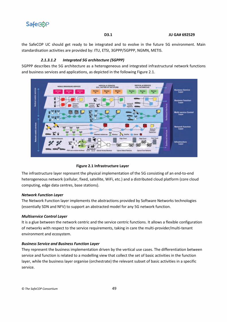
D3.1 JU GA# 692529
© The SafeCOP Consortium 49
the SafeCOP UC should get ready to be integrated and to evolve in the future 5G environment. Main
standardisation activities are provided by: ITU, ETSI, 3GPPP/5GPPP, NGMN, METIS.
2.1.3.1.2 Integrated 5G architecture (5GPPP)
5GPPP describes the 5G architecture as a heterogeneous and integrated infrastructural network functions
and business services and applications, as depicted in the following Figure 2.1.
Figure 2.1 Infrastructure Layer
The infrastructure layer represent the physical implementation of the 5G consisting of an end-to-end
heterogeneous network (cellular, fixed, satellite, WiFi, etc.) and a distributed cloud platform (core cloud
computing, edge data centres, base stations).
Network Function Layer
The Network Function layer implements the abstractions provided by Software Networks technologies
(essentially SDN and NFV) to support an abstracted model for any 5G network function.
Multiservice Control Layer
It is a glue between the network centric and the service centric functions. It allows a flexible configuration
of networks with respect to the service requirements, taking in care the multi-provider/multi-tenant
environment and ecosystem.
Business Service and Business Function Layer
They represent the business implementation driven by the vertical use cases. The differentiation between
service and function is related to a modelling view that collect the set of basic activities in the function
layer, while the business layer organise (orchestrate) the relevant subset of basic activities in a specific
service.

D3.1 JU GA# 692529
© The SafeCOP Consortium 50
Network slices and flexibility
A flexible network enables establishment of slices with all needed capabilities within the overall 5G
infrastructure. Such slice may be used by specific operators to offer ITS related services. The network slices
shall ensure prioritization of services like road safety over other internet traffic. In case network coverage
cannot be guaranteed, Device-to-Device must be available. Further it is possible to use smooth virtual cells.
The UE is dynamically served by one or more coordinated transmission points and the user is always
located at the centre of its virtual cell. Thereby best performance is always achieved and it is an effective
way to deal with mobility and interference issues in network densification.
2.1.3.1.3 5G protocol stack
Taking in account the pure telecommunication aspects, the following picture highlight the correspondence
between ISO and 5G layer organisation [ITU-M.2012], [ETSI302663], [ETSI202663]
Open wireless architecture (OWA)
The OWA is the 5G equivalent to the Physical and Medium Access Control ISO layers. The fundamental
concept of the 5G is how to best leverage existing technology investments in LTE while exploiting new
spectrum (i.e. new bands spanning a wide frequencies range) and new technology capabilities, combine
existing wireless networks (WiFi, 4G LTE, etc..) with capabilities provided by 5G itself. Some issues related to
the radio channel are: Orthogonal frequency division multiplex (OFDM), cooperative MIMO, Carrier
Aggregation, Relay Station, Heterogeneous Network (HetNet).
Network Layer
The network layer will be IPv6. The mobility support is based on the separation of network layer into two
sub-layer: Lower network layer (for each interface) and Upper network layer (for the terminal).

D3.1 JU GA# 692529
© The SafeCOP Consortium 51
Open Transport Protocol Layer (OTP)
It take in care the retransmission of lost or damaged TCP segments considering that losses can be caused not
only by network congestion but due to higher bit error ratio in the radio interface. In addition, different TCP
versions should be targeted to a specific wireless technology installed at the base stations.
Application Layer
It will implement intelligent QoS management over variety of networks providing the algorithms to select the
best wireless connection upon required QoS and personal cost constraints.
2.1.3.2 Experience of the standard at the different partners
The following experience on 5G is available at the different partners:
Qamcom: Experience through participation in other EU and national projects within 5G: FFI-5G,
mmMAGIC. Also technical expertise in beam forming and other signal processing in the air-interface.
Univaq: Research activities on 5G related to CoMP in small cells scenarios and backhaul/fronthaul
aspects.
2.1.3.3 Appropriateness of the standard with respect to the requirements of SafeCOP
2.1.3.3.1 5G technical requirements
The following ITU [ITU-M2002] [ITU-M2083] listed capabilities and the additional ones considered by 5GPPP
[5GPPP2015] can be considered as critical parameters for the different vertical sectors:
Data Rate: Required bit rate for the applications (user experienced data rate defined by ITU).
Maximum values in the order of Gb/s from Media & Entertainment use cases.
Mobility (speed): Maximum relative speed under which the specified reliability should be achieved.
Maximum value in the order of 500 km/h from Automotive use cases
E2E Latency: Maximum tolerable elapsed time between end-to-end transmission both for direct and
infrastructure mode. Minimum values of 100 µs to 10 ms from Factories use cases.
Density (number of devices): Maximum number of devices (vehicles in the case of Automotive) per
unit area. Up to 100/m2 from Factories use cases.
Reliability: Maximum tolerable packet loss rate at the application layer. Up to 99.99999% for eHealth
use cases.
Position Accuracy (Location): Maximum positioning error tolerated by the application. Minimum
values in the order of 0.3 m for Automotive use cases
Coverage: Area (geographic and/or population coverage) within which the application should
function correctly.
Communication range: Maximum distance between source and destination(s) of a radio transmission
within which the application should achieve the specified reliability.
Service Deployment Time: Time for setting up end-to-end logical network slices. Programmable
networks and multi-tenant capability in 5G will ensure speedy deployment of services
D3.1 JU GA# 692529
© The SafeCOP Consortium 52
Data Volume: Quantity of information transferred (downlink and uplink) per time interval over a
dedicated area (targets a maximum of 10 Tb/s/km2)
Autonomy: Time duration for a component to be operational without power being supplied. It relates
to battery lifetime, battery load capacity and energy efficiency.
Security: protection of resources encompassing several dimensions such as authentication, data
confidentiality, data integrity, access control, non-repudiation, etc.…
Identity: Characteristic to identify sources of content and recognise entities in the system.
2.1.3.3.2 Vehicular communication in cellular network
There are two broad categories of potential automotive applications; those based on wide-area
infrastructure-based communications (V2N), and those based on short-range communications (V2V, V2I,
V2P, etc.). Many infrastructure-based applications are likely to require reliable contiguous coverage, and
therefore need mobile bands preferably below a few GHz. Additional spectrum is likely to be required for
shorter range and extreme traffic density.
The following discussion presents the limitations of the current technologies to highlight the research and
improvement area of 5G [5GPPP2015], [ETSI302636], [ETSI302637], [ETSI302800], and [ETSI102637].
LTE
A cellular network like LTE, in contrast to 802.11p, is a scheduled network: transmission rates are granted by
network scheduler, in the LTE case located in E-UTRAN (Evolved Universal Terrestrial Radio Access Network)
Node B (eNB); collisions are avoided and mutual interference is minimized. This is of utmost importance
under high network load, as the scheduler may be able to provide Quality-of-Service (QoS) guarantees (e.g.,
a guaranteed bit rate or delay) to different applications by allocating radio resources based on their priority
and QoS class parameters and by performing admission control.
In contrast, several drawbacks are recognised:
● higher number of users results in increased latency;
● every data packet must do one uplink and one downlink;
● it is not optimized for small amounts of data and not available out of coverage (e.g., in a tunnel,
underground parking lot, rural area, etc...);
● device to device communication or instant time delivery of small messages have not been
prioritized;
● the infrastructure may become a single point of failure (e.g., in case of eNB failure).
Those issues has been addressed by the Proximity Services (ProSe) new feature, being specified within 3GPP
[3GPP2016]. ProSe allows User Equipments (UE) within communication range, regardless of whether they
are in or out of E-UTRAN coverage, to discover and communicate with each other directly without traversing
the network infrastructure.

D3.1 JU GA# 692529
© The SafeCOP Consortium 53
ProSe is enabled by a new E-UTRAN capability known as “sidelink” (SL). Sidelink transmissions occur within a
subset of the uplink time-frequency resources and use the same transmission scheme as uplink
transmissions, i.e., Single Carrier Frequency Division Multiple Access (SC-FDMA). There are two sidelink
transmission modes: in scheduled mode (“mode 1”), only available when in coverage. the eNB determines
the radio resources used for sidelink communication; in autonomous mode (“mode 2”), resources on its own
from a (pre)configured resource pool.
The ProSe specification do not cover the whole V2X requirements (actually, it has been designed with the
requirements of public safety and commercial consumer applications in mind). Enhancements are required
for:
● high speeds (e.g., in highway scenarios),
● guaranteed QoS and
● support for one-to-all (broadcast) as well as one-to- one (unicast) communication.
Some other limitations relate to the sidelink frame structure and synchronization procedures that were
designed only for lower mobility. Further limitations relate to the autonomous resource allocation scheme
that was designed assuming the typical traffic patterns and load of Public Safety communication and
commercial discovery, which differ substantially from the operating conditions of V2X traffic.
2.1.3.3.3 5G research and innovation
5G will most likely integrate in a heterogeneous network the already available communication technologies
like LTE ProSe and IEEE 802.11p and will provide the necessary extensions to enable the future V2X use cases.
5G, as a general objective, will exploit safety, security and privacy support both by the infrastructure and
application point of view.
By application point of view, the 5G integrated architecture will allow news business models characterised
by services and applications ensemble with an increasing interaction, cooperation and complexity level as
well as a great level of flexibility for service tailoring on customers’ demands.
At infrastructure level, as presented in the previous sections, the research aim to satisfy the most vertical use
case requirements, improving and enhancing the current technologies in an evolutionary scenario, thus
solving the foreseen weakness of LTE and ProSe for the vehicular use case.
Summarising the set of the issues that need to be addressed by SafeCOP research the following points are
foreseen:
Redundancy and scalability issues require to be approached at physical, link and network layer supporting
multiple parallel channels and links (e.g. using MIMO) and providing a meshed network schema with multiple
alternative and multi hop routing possibilities.

D3.1 JU GA# 692529
© The SafeCOP Consortium 54
An extended range coverage should also be guarantee depending on the traffic scenarios (e.g. long range for
high speed, high distances vehicles in highway routes vs limited speed, very short distance vehicle for high
dense traffic in downtown streets)
Reliable and robust communication is required especially in critical environmental condition, e.g. controlling
transmission power and channel modulation satisfying also energy optimisation.
Timeliness is another important characteristics for vehicular use case; two major issues are the guaranteed
latency and a fast connection procedure in a highly dynamic network configuration where vehicle (i.e. nodes)
should continuously enter and leave the platooning.
On the other hand the security, in particular the source trustiness, must be guaranteed adopting suitable fast
strategies, as opposite to the current authentication procedures involving central manager supervision.
Another important issue to be considered is the preparation of the new development for the future 5G
migration and support. The 5G integrated architecture must be taken in care. The high virtualized
environment give the means to deploy a flexible service architecture and deployment.
2.2 WLAN
2.2.1 IEEE 802.11 b/g/n
2.2.1.1 Short description of the standard
Wireless Local Area Network (WLAN) is based on IEEE 802.11 standard and is also popular by the name as
Wireless Fidelity (Wi-Fi). The 802.11 standard is divided into various sub-categories. Each of these subsets,
such as 802.11 b, and 802.11 g, 802.11 n represents a different IEEE protocol. The following table shows a
comparison between IEEE 802.11a/b/g/n standards:
Standard Spectrum Compatible with Maximum physical rate
802.11 b 2.4 GHz 802.11 11 Mbps
802.11 g 2.4 GHz 802.11/802.11b 54 Mbps
802.11 n 5 or 2.4 GHz 802.11b/g 300 Mbps(2 streams)
2.2.1.2 Experience of the standard at the different partners
The following experience on IEEE 802.11 is available at the different partners:
● MDH:
○ OMNET simulator
● UNIVAQ: ○ OMNET simulator ○ Ad Hoc Networking

D3.1 JU GA# 692529
© The SafeCOP Consortium 55
2.2.1.3 Appropriateness of the standard with respect to the requirements of SafeCOP
802.11 b/g/n limitations and drawback
The main drawback of the IEEE 802.11 b standard is frequency band become common and interference from
the other networking technology such as cordless phone, Bluetooth and so on. Moreover bit rate is too low
for many emerging applications. On the other hand it is widely deployed and it has higher range.
The IEEE 802.11 g standard has high bit rate in 2.4 GHz spectrum, but the major disadvantage is that
appliances may interfere on the unregulated signal frequency.
The major drawback of the IEEE 802.11 n standard is the difficulty of implementation. Moreover the use of
multiple signals may greatly interfere with nearby 802.11b/g based networks.
Vehicle communication
The main goal in vehicle communication is finding the best trade-off between performance (i.e., maximize
speed) and safety (i.e., avoid collision). This overview addresses the use of the 802.11b/g/n protocols for
vehicle communication.
A new wireless protocol is needed in this context for the following reasons. Traditional WiFi (a/b/g/n/ac) was
designed for mobility but not the speeds vehicles normally attain. Two vehicles traveling toward each other
at 60 mph will have less than 6 seconds to pass messages back and forth if we assume a maximum
communication range of 300 meters. As a result, certain changes had to be made to ensure most of this time
could be used for communication and not wasted on authentication and security features (these functions
can be handled at higher layers). 802.11p removes some of the handshaking requirements and let vehicles
enable faster message exchange. A major reason the new segment of spectrum (and protocol) is needed is
the high volume of traffic that exists on the existing WiFi channels. Many of the messages dedicated to
vehicles are safety related and delays caused by interference are intolerable.
[Ras13] demonstrates experimentally the viability of the wireless technology IEEE 802.11b for inter-vehicle
communications. Although IEEE802.11b was designed for low mobility, indoor scenarios, it shows that is
possible to use it in high-mobility, outdoor scenarios where vehicles reach relative speeds of 260 km/h. In
urban scenarios, however, it measures loss percentages in the 20%-80% range. This let's vehicle platooning
impractical in virtue of the delay introduced by the need of re-transmitting lost packets. This topic is detailed
later in the 802.11p section. The round trip time (RTT) takes into account the time for sending back an
acknowledgement of correct receipt from the destination to the source. Under perfect line of sight
conditions, the measured RTT for interurban scenarios is 8 ms with speed at 140-160 km/h. Every slop in the
road however produces a peak of low connectivity where many packets are lost. In the urban scenario, high
influence of the environment is observed. The numerous buildings that surround the road produced several
signal reflections that increased the packet error rate. This produces an important decrease on the received
throughput and the communication distance. Moreover, an important increase on the delay and jitter is
produced.

D3.1 JU GA# 692529
© The SafeCOP Consortium 56
Comparative performance evaluations [Bil13] show that the IEEE 802.11p achieves higher network
throughput, low end-to-end delay, and higher delivery ratio compared to IEEE 802.11b. The study is based
on real-world measurements and radio propagation models of vehicle networks in different environments,
including highway, rural, and urban areas. The network throughput results of IEEE 802.11p and IEEE 802.11b
can be ordered from higher throughput to lower throughput as the environment switches from rural to urban
and highway areas.
In [Xuw14], IEEE 802.11g is used to analyse the effects of multi-path interference. The communicating nodes
reside on laptop computers and are moved from a short distance of 20 m to 95 m. It is noted that latency
between 100 ms to 600 ms is typical under line of sight between computers. In a field with many trees, the
transmission pathways are obstructed. The communication latency increases significantly to a range of 3.4 s.
2.2.2 IEEE 802.11p
2.2.2.1 Short description of the standard
IEEE 802.11p is derived from the base standard 802.11 with some changes to fit the vehicular environment,
e.g., the access point functionality has been removed. Hence, the network contains no access points or base
stations, and consequently, will never experience coverage problems: if no one is there to communicate with,
no one is there to collide with. This is the main benefit of IEEE 802.11p compared to all other technologies,
that it works in ad hoc mode and does not rely on coverage. An added benefit is also that the ad hoc mode
reduces delay, as messages do not have to take the detour around the access point, or base station.
The MAC algorithm deployed by 802.11p is found in the 802.11-2012 and it is called enhanced distributed
coordination function (EDCA). It is based on the basic DCF but adds QoS attributes. DCF uses CSMA/CA and
was already present already in the first version of 802.11 released in 1997. The EDCA includes some enhanced
features such as prioritized access to the channel by using queues with different arbitration interframe spaces
(AIFS). This will ensure that data traffic with higher priority (e.g., video, IP telephony) has a higher probability
of channel access compared to low priority traffic (e.g., background, best effort). However, the different QoS
classes will not ensure timely channel access and thus, there will still be problems with collisions, especially
during high utilization periods.
The physical layer of 802.11p is OFDM detailed in Clause 18 of IEEE 802.11-2012. There are 52 subcarriers,
where 48 are used for data and 4 are pilot carriers. The OFDM PHY layer supports three different frequency
channel widths; 5 MHz, 10 MHz, and 20 MHz. 802.11p is using 10 MHz channels whereas AP based WLAN
operation is usually using 20 MHz channels. The OFDM symbol duration and subcarrier frequency spacing
are depending on channel widths, i.e., the number of subcarriers is fixed. The duration of one OFDM symbol
in 802.11p is 8 μs including guard interval.
In Europe, ETSI is responsible for developing the whole protocol stack including vehicle-centric road traffic
safety applications, whereas applications orienting towards road traffic efficiency utilizing road infrastructure
are under the responsibility of CEN.

D3.1 JU GA# 692529
© The SafeCOP Consortium 57
In Europe, 30 MHz has been set aside for vehicular communications at 5.875-5.905 GHz, solely intended for
road traffic safety applications. Non-safety related applications are directed to a 20 MHz band at 5.855-5.875
GHz. The dedicated frequency bands have been divided into 10 MHz frequency channels. Due to the
proximity of these bands to the frequency band used for ETC in Europe (5.795-5.805 GHz) ETSI TC ITS must
also develop mitigation techniques to avoid to interfere with the ETC systems. There is no cost associated
with using this frequency band (it is license free). However, the usage of it is regulated in EN 302 571
specifying requirements on output power limits, spectrum masks etc.
2.2.2.2 Appropriateness of the standard with respect to the requirements of SafeCOP
802.11p limitations and drawback
This protocol has been specifically designed for vehicular cooperation, supporting direct communication, also
in absence of network coverage, with low latency and traffic prioritisation. Intermittent network coverage is
still required to support some security features, as well as internet connection. Roadside Units may be used
to extend communication range and network coverage, especially in specific points like at intersections or
close to traffic lights.
Several drawbacks are recognised like: throughput and delay degradation when network load increase; the
“hidden node” problem, lack in spectrum efficiency, etc. detailed in [5GPPP]. These drawbacks are, however,
associated with another type of applications. In contrast, co-CPS typically require a predictable delay, but not
necessarily high throughput. Further, the hidden node problem generally only appears in centralized
networks, i.e., including an access point or base station. In ad hoc networks, especially when broadcast is the
main way of communication, hidden nodes are generally not problematic [
Some of those drawbacks affect security and safety issues:
● the data congestion should affect safety message broadcast repetition time reducing it below
acceptable values;
● the security system uses digital signatures to guarantee the integrity and authenticity of a message,
to generate signatures and allow for verification, private-public-key pairs and certificates are
required, and the latter are retrieved from a Public Key Infrastructure (PKI);
● the privacy of the connected vehicles needs to be preserved to prevent personal data, e.g., location
and driving habits, to be revealed to unauthorized entities. The pseudonym certificates are used
with the active dissemination of revocation information, not fulfilling any future;
● requests for pseudonym certificates;
● the utilisation of a PKI centralized management entity, however, can lead to a large delay to revoke
certificates and, hence, can be harmful to safety applications;
● furthermore, it results in a large overhead for cryptography to be signalled and processed.
Using the cellular network as a trusted entity might help to accelerate revocation of certificates, simplify
update procedures and lower the required overhead.
Vehicle platooning

D3.1 JU GA# 692529
© The SafeCOP Consortium 58
The appropriateness of 802.11p with respect to safety is now addressed. We consider state of the art of
protocol performance under realistic scenarios of vehicle platooning.
The main goal in vehicle platooning is finding the best trade-off between performance (i.e., maximize speed
and minimize vehicles reciprocal distance) and safety (i.e., avoid collision). The topic is of interest because
the largest part of the literature focuses on advanced control schemes, without modelling the
communication medium properly. Delay of communication is typically considered as a fixed delay or through
probabilistic models. This allows the analytical derivation of string stability models [Onc11] under some
hypotheses of the dynamical system, but it may be unreliable under realistic conditions. Two branches are
evident from the literature in this respect: the derivation of simple models of the delay bound that
guarantees safety (see, e.g., section IV.C of [Xuw14]) and brute force simulation with visualization of safety
regions under a reduced set of parameters [Jin14, Seg13]. The rest of the paragraph deals with performance
of the communication medium of vehicle platooning under realistic scenarios.
Inter-vehicle communications can be realized by using infrared, radio, or microwaves waves. In IEEE 802.11p,
a bandwidth 75 MHz is allocated in the 5.9 GHz band for dedicated short range communication (DSRC)
[Haf13]. Signal strength typically decreases inversely proportionally to the cubic of the distance between the
two vehicles. Obstructions such as buildings, bridges, other vehicles are other factors of channel degradation
together with fading, interference from other vehicles, Doppler shifts and weather conditions. The
performance metrics of interest are: loss and delay of the packets. The round trip time (RTT) takes into
account the time for sending back an acknowledgement of correct receipt from the destination to the source.
[Bai10] reports experimental data of IEEE 802.11p DSRC from a team of vehicles driving on certain Michigan
highways. Package Delivery Rates (PDR) is measured under different driving conditions, traffics, and
surroundings. A typical curve is presented below. Hop by hop communication is considered in the example;
it means only consecutive vehicles communicate directly. PDR is highly affected by the modulation rate of
the channel. The topical element affecting performance in the 802.11 protocols is sharing the communication
medium via contention and retransmission. [Bai10] reports that at 6 Mbps of modulation rate, a successful
RTT at the first tentative of channel access implies a delay of 100 ms, but this happens in the 75% of the
cases. Subsequent transmissions, i.e., up to three to achieve a PDR over 98.5% implies a delay of 300 ms. The
situation is even worse with 18 Mpbs of modulation rate. This example may help understand the relevance
of the loss-delay reciprocal influence in the case the medium is shared among the nodes with
retransmissions.

D3.1 JU GA# 692529
© The SafeCOP Consortium 59
Fig. 2.2.2.2_1. Package Delivery Rates of 802.11p DSRC along a highway under 5 hops communication.
[Nee05] shows the detrimental impact of multi-hop communication in a similar highway environment
(picture below). The delay starts from 100 ms in the figure.
Fig. 2.2.2.2_2. Package Delivery Rates of 802.11p DSRC along a highway under hop-by-hop
communication.
In order to help understand the impact of delay on safety, an example is reported from [Xuw14]. Three cars
follow the platoon under the following conditions: two hop communication, strength of the breaking force
added to the content of communication packets and a threshold based (based on distance) breaking force
control is applied. Initial distance and speed are also other facts to be taken into account. The following table
summarizes the distance between the 2nd and 3rd vehicle after the braking event brought all vehicles to stop.
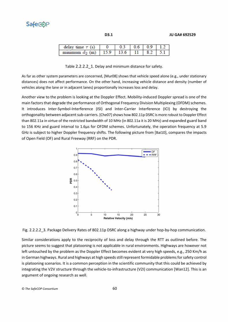
D3.1 JU GA# 692529
© The SafeCOP Consortium 60
Table 2.2.2.2_1. Delay and minimum distance for safety.
As far as other system parameters are concerned, [Mur08] shows that vehicle speed alone (e.g., under stationary
distances) does not affect performance. On the other hand, increasing vehicle distance and density (number of
vehicles along the lane or in adjacent lanes) proportionally increases loss and delay.
Another view to the problem is looking at the Doppler Effect. Mobility-induced Doppler spread is one of the
main factors that degrade the performance of Orthogonal Frequency Division Multiplexing (OFDM) schemes.
It introduces Inter-Symbol-Interference (ISI) and Inter-Carrier Interference (ICI) by destroying the
orthogonality between adjacent sub-carriers. [Che07] shows how 802.11p DSRC is more robust to Doppler Effect
than 802.11a in virtue of the restricted bandwidth of 10 MHz (in 802.11a it is 20 MHz) and expanded guard band
to 156 KHz and guard interval to 1.6μs for OFDM schemes. Unfortunately, the operation frequency at 5.9
GHz is subject to higher Doppler frequency shifts. The following picture from [Bai10], compares the impacts
of Open Field (OF) and Rural Freeway (RRF) on the PDR.
Fig. 2.2.2.2_3. Package Delivery Rates of 802.11p DSRC along a highway under hop-by-hop communication.
Similar considerations apply to the reciprocity of loss and delay through the RTT as outlined before. The
picture seems to suggest that platooning is not applicable in rural environments. Highways are however not
left untouched by the problem as the Doppler Effect becomes evident at very high speeds, e.g., 250 Km/h as
in German highways. Rural and highways at high speeds still represent formidable problems for safety control
is platooning scenarios. It is a common perception in the scientific community that this could be achieved by
integrating the V2V structure through the vehicle-to-infrastructure (V2I) communication [Wan12]. This is an
argument of ongoing research as well.
D3.1 JU GA# 692529
© The SafeCOP Consortium 61
2.2.2.3 Experience of the standard at the different partners
The following experience on IEEE 802.11p is available at the different partners:
● MDH/SICS:
○ Matlab simulator
○ Veins and Plexe simulator platforms (a bidirectional coupled simulators, including
OMNeT++ and SUMO) especially for vehicular scenarios and platooning applications. Veins
couples SUMO and the INET framework from OMNeT++ through a TCP connection.
OMNeT++ is therefore able to send commands to vehicles from the network simulator,
influencing their speed or path. Plexe is an extension of Veins which permits the realistic
simulation of platooning application. It features realistic vehicle dynamics and several
cruise control models, permitting the analysis of control systems, large-scale and mixed
scenario, as well as networking protocols and cooperative manoeuvres.
○ Design and evaluation of several standard-based MAC layer protocols, and extensions
thereof (replacing CSMA with STDMA, or using TDMA on top) for vehicular ad hoc networks
and platooning, where the latter uses TDMA on top and relay assignment for increased
reliability given a deadline
○ Experience from standardization within ETSI TC ITS
● CNR-IEIIT/Impara:
○ Simulation of vehicle platooning under variation of communication (e.g., delay, loss),
environmental (distance, speed) and control (strength of brake force) metrics to build
collision prediction via machine learning
○ Experience from standardization within ETSI BSM
● UNIVAQ: ○ OMNET simulator with VEINS and ARTERY frameworks ○ Experimentations in controlled environment and in the open field with Cohda MK5 On
Board Units ○ Research on congestion mitigation inside the ETSI ITS-G5 ○ Early stage research with the Ettus USRP SDR solution
2.2.3 Next Generation Ham Radio protocol (DNV GL, [email protected], MARO)
2.2.3.1 Short description of the standard
Next Generation Ham Radio (NGHam) protocol is a proprietary protocol for packet based amateur radio
communication developed by Maritime Robotics (MARO). It is a Very High Frequency (VHF) radio protocol
which specifies both physical layer (PHY) and media access control (MAC) layer functions. It is a simple and
light-weight communication protocol while having some desirable features, including it can achieve
robustness by decoding with much lower signal-to-noise ratio (SNR); the throughput can be high because of
the short preamble and high chance of successful packet reception; it can obtain better spectral efficiency
due to the reduced frequency deviation.
The frequency range of NGHam is: Receiver (RX): 136 – 174 MHz; Transmitter (TX) – amateur version: 144 –
148 MHz; TX – professional version: 140 – 165 MHz.

D3.1 JU GA# 692529
© The SafeCOP Consortium 62
The modulation schemes supported by NGHam are 2-GMSK (Gaussian Minimum Shift Keying) and 4-GMSK.
The data rates which NGHam supports are: for a channel with 25 KHz bandwidth, the data rate is 9.6 Kbps if
using 2-GMSK and the data rate is 19.2 Kbps if using 4-GMSK; for a channel with 12.5 KHz bandwidth, the
data rate is 4.8 Kbps if using 2-GMSK and the data rate is 9.6 Kbps if using 4 – GMSK.
NGHam supports carrier sense multiple access (CSMA) and time division multiple access (TDMA) schemes. In
UC2, TDMA is implemented. Depending on the number of connected unmanned surface vehicles (USVs), the
slot time can be manually configured at the vehicle control station (VCS). If a USV connects/disconnects
to/from the VCS, the VCS has to re-calculate the TDMA frame and allocate the time slots to each USV
accordingly.
2.2.3.2 Experience of the standard at the different partners
The following experience on NGHam protocol is available at the different partners:
● MARO
○ Owns NGHam protocol (proprietary protocol)
○ Implements NGHam protocol on various USVs developed by MARO
2.2.3.3 Appropriateness of the standard with respect to the requirements of SafeCOP
2.2.3.3.1 Timeliness
NGHam protocol is mainly used for transmitting small sizes of messages (e.g. telemetries encapsulating mode
status/position/speed of VCS/USV) between the VCS and USVs. In general, it meets the timeliness
requirements for message transmission of UC2 if the configuration is done properly. For instance, the time
slot size of TDMA is configured properly in order to guarantee the messages delivered in a timely manner.
However, as the number of connected USV(s) increases, the waiting delay of a message can be prolonged. In
order to guarantee the timeliness of each type of messages, the worst-case end-to-end delay should be
analysed. This will be a task of UC2 WP3 and will be carried by DNV GL.
2.2.3.3.2 Safety
NGHam protocol can be used to transmit safety-critical control commands from the VCS to USVs. The
protocol adopts Reed Solomon FEC to ensure a certain level transmission reliability and data integrity.
However, the protocol itself does not guarantee the safety-critical control commands transmitted
successfully. E.g., packets which carry safety-critical control commands are corrupted/lost during
transmission. It depends on the implementation and configuration of NGHam protocol, and manual
operation to achieve the successful transmission of safety-critical control commands encapsulated into
NGHam packets. Therefore, the corresponding safety requirements regarding to wireless communication
should be specified and implemented additionally. If the requirements specified in WP1 are not sufficient to
fulfil the safety requirements of communication, the further safety analysis has to be conducted in this WP.

D3.1 JU GA# 692529
© The SafeCOP Consortium 63
2.2.3.3.3 Security
NGHam protocol does not specify any security mechanism. Therefore, security measures/mechanisms have
to be specified as separate requirements and be implemented in addition to the protocol implementation.
WP1 has specified some security requirements regarding to wireless communication. However, it is
necessary to conduct some analysis to understand how the potential security risks (e.g. threats,
vulnerabilities) can impact the safety. This analysis will be done in this WP.
2.3 WPAN
2.3.1 IEEE 802.15.4
2.3.1.1 Short description of the standard
IEEE 802.15.4 was first published in 2003 for WPAN (Wireless Personal Area Networks). The protocol defines
only the physical and data-link layers, a few proposals such as the ZigBee and the RPL protocols have been
complement the communications stack.
In the IEEE 802.15.4 standard, devices can be classified into Fully Functional Devices (FFD) and Reduced
Functional Devices (RFD). The Full Function Devices (FFD) have all the capabilities such as sensing, processing,
memory and communicating. They have the ability to act as a Personal Area Network (PAN) Coordinator. The
PAN coordinator is the principal controller to which other devices may be associated. It is responsible for the
local synchronization in its range. It also serves as a data router to its neighbours. The Reduced Function
Device (RFD) is typically the end node of an IEEE 802.15.4. It is simple and do not have the need to send large
amounts of data and are typically only associated with a single FFD at a time.
IEEE 801.15.4 operates in three different frequency bands: 2.4 GHz (with 16 channels); 915 MHz (with 10
Channels) and 868 MHz (with only one channel). The MAC layer for IEEE 802.15.4 is designed to work both
on a beacon enabled and on a non-beacon enabled mode. The beacon enabled mode is used for supporting
time sensitive applications. The beacon enabled mode is supported by a superframe which has a Contention
Access Period (CAP) and the Contention Free Period (CFP). During the CAP the nodes in the network contend
with each other to access the channel using slotted CSMA/CA. The CFP is composed of 15 Guaranteed Time
Slots (GTS) which are used by nodes that require guaranteed bandwidth. These timeslots are allocated to a
set of nodes so that they do not contend with each other for transmitting in the channel.
2.3.1.2 Experience of the standard at the different partners
The following experience on IEEE 802.15.4 is available at the different partners:
● ROT:
○ Software:
■ TinyOS, MAC TKN15.4.

D3.1 JU GA# 692529
© The SafeCOP Consortium 64
○ Hardware:
■ MEMSIC IRIS mote, MEMSIC Telosb mote.
■ Sensorboard MEMSIC MTS420CC.
● ISEP:
○ Software:
■ ISEP’s Open-ZB framework encompasses several contributions to this protocol:
simulation models (OPNET simulator), protocol stack implementation (beacon-
enabled mode), and diverse network planning tools.
■ TKN15.4 network stack.
■ OS: Extensive work over TInyOS, Contiki, ERIKA and nanoRK operating systems.
○ Hardware:
■ MEMSIC TelosB, MICAz, IRIS and Evidence FLEX boards platforms.
■ Other: Several sensorboard models and network analysers.
● MdH:
○ Evaluation:
■ Analytical evaluations of several extensions to 802.15.4, by using TDMA on top of
commercial transceivers, to meet the requirements of reliability and predictable
delay of co-CPS.
■ OMNeT++
● UNIVAQ:
○ Middleware:
■ Agilla/Agilla2, MoteRunner
○ Software:
■ OSs: TinyOS, Contiki
■ Protocol Stacks: MAC TKN15.4, Atmel MAC 15.4, OpenZB, OpenWSN
■ LabSMILING (SW): remote testbed management
○ Hardware:
■ Sensor nodes and boards: several MEMSIC/ADVANTICSYS/Atmel-based
■ LabSMILING (HW): up to 100 sensor nodes testbed
2.3.1.3 Appropriateness of the standard with respect to the requirements of SafeCOP
2.3.1.3.1 Timeliness
Timeliness guarantee is an important feature of the IEEE 802.15.4 protocol.
IEEE 802.15.4 protocol provides timeliness guarantees when operating in beacon-enabled mode. This mode
offers the possibility of allocating/deallocating time slots in a superframe, called Guaranteed Time Slots
(GTSs), and therefore the possibility of providing predictable minimum service guarantees. Having a
minimum service guarantee, it is possible to predict the worst-case timing performance of the network [1].

D3.1 JU GA# 692529
© The SafeCOP Consortium 65
2.3.1.3.2 Scalability
The IEEE 802.15.4 has a very limited superframe and fixed number of GTS timeslots for determinism based
transmissions. Though the protocol is very effective on determinism for limited number of nodes transmitting
data, it lacks methods to cover a larger geographical span.
2.3.1.3.3 Safety
The cryptographic mechanism in the IEEE 802.15.4 standard is based on symmetric-key cryptography.
This mechanism uses keys provided by higher layer processes and it assumes a secure implementation of
cryptographic operations and secure and authentic storage of keying material.
The cryptographic mechanism provides particular combinations of the following security services:
· Data confidentiality: Assurance that transmitted information is only disclosed to parties for which it is
intended.
· Data authenticity: Assurance of the source of transmitted information (and, hereby, that information was
not modified in transit).
· Replay protection: Assurance that duplicate information is detected.
The actual frame protection provided can be adapted on a frame-by-frame basis and allows for varying levels
of data authenticity (to minimize security overhead in transmitted frames where required) and for optional
data confidentiality. When nontrivial protection is required, replay protection is always provided.
Cryptographic frame protection may use a key shared between two peer devices (link key) or a key shared
among a group of devices (group key), thus allowing some flexibility and application-specific trade-offs
between key storage and key maintenance costs versus the cryptographic protection provided. If a group key
is used for peer-to-peer communication, protection is provided only against outsider devices and not against
potential malicious devices in the key-sharing group [1].
2.3.2 ZigBee
2.3.2.1 Short description of the standard
The ZigBee Alliance has developed the ZigBee protocol over the IEEE 802.15.4 Physical and Media Access
Control layer. The first release was in 2004, where the last one in 2015: ZigBee 3.0 defines and unifies all
ZigBee application standards (Remote control, Heathcare, Light link...); making devices, that provide different
specific services, interoperate seamlessly. The ZigBee technology ensures a potential wide coverage range,
long autonomy of device battery life (several days in TX status, years in idle status), low cost but low data
rate.

D3.1 JU GA# 692529
© The SafeCOP Consortium 66
Figure 2.2 ZigBee Standard
IEEE802.15.4 and ZigBee are complementary protocol.
The IEEE802.15.4 PHY and MAC layer and ZigBee Stack (NWT, SSP, security function API layer, and application
support sub-layer) constitute a compliant platform, while the APL Application profiles are certified products.
Vendor are allowed to create their specific extensions, so one vendor devices may implement multiple
profiles therefore a node potentially comprehends multiple end-points for different fields of application.
Interoperability
The ZigBee technology allows different vendor product, with different proprietary profiles, joining the
network; it also supports both beacon-enabled and not beacon-enabled network.
2.3.2.2 Experience of the standard at the different partners
The following experience on ZigBee is available at the different partners:
● ROT:
○ Software: TinyOS, MAC TKN15.4;
○ Hardware: Iris mote (MEMSIC), Telosb mote (MEMSIC), sensorboard MTS420CC (MEMSIC).
2.3.2.3 Appropriateness of the standard with respect to the requirements of SafeCOP
2.3.2.3.1 Timeliness
ZigBee protocol provides timeliness guarantees when operating in beacon-enabled mode. This mode offers
the possibility of allocating/deallocating time slots in a superframe, called Guaranteed Time Slots (GTSs), and
therefore the possibility of providing predictable minimum service guarantees. Having a minimum service
guarantee, it is possible to predict the worst-case timing performance of the network [1].

D3.1 JU GA# 692529
© The SafeCOP Consortium 67
2.3.2.3.2 Safety
Security services provided for ZigBee include methods for key establishment, key transport, frame protection,
and device management [139]. The ZigBee Alliance describe the security functionalities based on an open
trust model for a device whereby the different layers of the communication stack and all applications running
on a single device trust each.
The ZigBee specifications provide different means to achieve the following security requirements:
● Freshness: ZigBee devices maintain incoming and outgoing freshness counters to maintain data
freshness. These counters are reset every time a new key is created. Devices that communicate once per
second will not overflow their freshness counters for 136 years.
● Message Integrity: ZigBee specifications provide options of providing 0-, 32-, 64- or 128-bit data
integrity for the transmitted messages. The default is 64-bit integrity.
● Authentication: Network level authentication is achieved by using a common network key. This
prevents outsider attacks while adding very little in memory cost. Device level authentication is achieved by
using unique link keys between pairs of devices. This prevents insider and outsider attacks but has higher
memory cost.
● Encryption: ZigBee uses 128-bit AES encryption. Encryption protection is possible at network level or
device level. Network level encryption is achieved by using a common network key. Device level encryption
is achieved by using unique link keys between pairs of devices. Encryption can be turned off without
impacting freshness, integrity, or authentication as some applications may not need any encryption. [1]
2.3.3 6loWPAN
2.3.3.1 Short description of the standard
6loWPAN stands for “IPv6 over Low-power Wireless Personal Area Networks”. Low-power Wireless Personal
Area Networks (LoWPANs) use the 802.15.4 standard. 6loWPAN is a protocol stack that enables nodes to
communicate with each other using IPv6.
The stack of 6loWPAN includes MAC and PHY layers from low energy efficient protocols such as IEEE 802.15.4.
Additionally, it also provides RPL in the network layer in order to ensure effective routing.
Figure 2.3. 6LowPAN Stack

D3.1 JU GA# 692529
© The SafeCOP Consortium 68
6loWPAN is one of the initial cross-layer low power enabled protocols that supports mesh networking.
The uplink to the Internet is handled by an Access Point (AP) which acts as an IPv6 router. Different devices
such as PCs, servers, etc., are connected to the AP. The 6LoWPAN network is connected to the IPv6 network
using an edge oriented router. The edge router performs the following functions: data exchange between
6LoWPAN devices and the Internet; local. The uplink to the Internet through the Access Point (AP) which acts
as an IPv6 router; the generation and maintenance of the radio subnet (the 6LoWPAN network).
2.3.3.2 Experience of the standard at the different partners
The following experience on 6loWPAN is available at the different partners:
● ISEP:
○ Software Y
○
2.3.3.3 Appropriateness of the standard with respect to the requirements of SafeCOP
2.3.3.3.1 Timeliness
Some of 6LoWPANs main features are fragmentation (i.e.) the reassembly of IPv6 packets, compression of
IPv6 and UDP/ICMP headers, mesh routing support, and very low processing costs. The adaptation layer of
6LoWPAN allows IPv6 packets to be carried efficiently within small link layer frames, which are defined by
IEEE 802.15.4. It also provides an auto configuration process in which the devices create their own IPV6
addresses. Combined with routing capabilities of RPL, 6LoWPAN is capable of not only maintain a large
mesh network but also can meet stringent timelines.
2.3.3.3.2 Safety
6LoWPAN is a protocol stack for seamlessly integrating 802.15.4- based wireless sensor networks with IPv6
networks. The security of 6LoWPAN widely depends on the 802.15.4 security sublayer.
Security requirements for 6LoWPAN can be listed as it follow:
● Data Confidentiality;
● Data Authentication;
● Data Integrity;
● Data freshness;
● Availability;
● Robustness;
● Resiliency;
● Resistance;
● Energy efficiency;
● Assurance.
In order to provide security in 6LoWPANs, a robust encryption mechanism must be in place. Only the non-
tamperable keys can provide an encryption infrastructure that is thorough enough to provide a wide range
of security services. [1]

D3.1 JU GA# 692529
© The SafeCOP Consortium 69
2.3.4 RPL
2.3.4.1 Short description of the standard
IPv6 Routing Protocol for Low Power and Lossy Networks (RPL) is a protocol designed for Low power and
Lossy Networks (LLN). It integrates technologies such as IEEE 802.15.4 and IPv6 protocols. In order to ensure
an effective routing in low power, IETF ROLL working group proposed a routing protocol called RPL. RPL
supports both mesh as well as hierarchical topologies. RPL is specifically designed to support networks that
are prone to highly exposed packet losses and limited resources in terms of computation and energy. It
supports point-to-point and point to- multi point traffic.
RPL is a distance vector (DV) source routing protocol and is based on hierarchical Directed Acylic graphs
(DAGs). Contrast to a classical tree, in a DAG a node can associate itself with many parent nodes. The
destination nodes of an RPL is called a sink and the nodes through which a route is provided to internet are
called gateways. RPL organizes these nodes as Destination-Oriented DAGs (DODAGs). Several DODAGs can
be present in a network. Every node in a DODAG has a rank, which is the individual position of a node with
respect to its neighbours in the system. A basic example of an RPL network is shown in Figure below The rank
increases outwards from the DODAG root as shown in Figure. In order to construct a network topology, every
router in the system identifies and associates with a parent in a specific DODAG root. This is done based on
an objective function. Objective function helps in computing the rank of a node(s) and providing them an
optimal routing path using metrics such as latency and power efficiency.
2.3.4.2 Experience of the standard at the different partners
The following experience on RPL is available at the different partners:
● ISEP:
○ Software Y
○
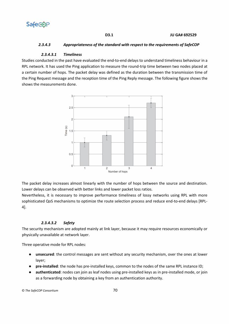
D3.1 JU GA# 692529
© The SafeCOP Consortium 70
2.3.4.3 Appropriateness of the standard with respect to the requirements of SafeCOP
2.3.4.3.1 Timeliness
Studies conducted in the past have evaluated the end-to-end delays to understand timeliness behaviour in a
RPL network. It has used the Ping application to measure the round-trip time between two nodes placed at
a certain number of hops. The packet delay was defined as the duration between the transmission time of
the Ping Request message and the reception time of the Ping Reply message. The following figure shows the
shows the measurements done.
The packet delay increases almost linearly with the number of hops between the source and destination.
Lower delays can be observed with better links and lower packet loss ratios.
Nevertheless, it is necessary to improve performance timeliness of lossy networks using RPL with more
sophisticated QoS mechanisms to optimize the route selection process and reduce end-to-end delays [RPL-
4].
2.3.4.3.2 Safety
The security mechanism are adopted mainly at link layer, because it may require resources economically or
physically unavailable at network layer.
Three operative mode for RPL nodes:
● unsecured: the control messages are sent without any security mechanism, over the ones at lower
layer;
● pre-installed: the node has pre-installed keys, common to the nodes of the same RPL instance ID;
● authenticated: nodes can join as leaf nodes using pre-installed keys as in pre-installed mode, or join
as a forwarding node by obtaining a key from an authentication authority.
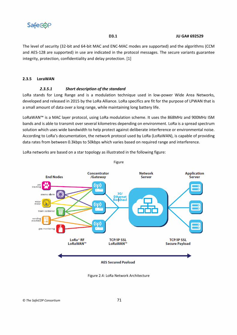
D3.1 JU GA# 692529
© The SafeCOP Consortium 71
The level of security (32-bit and 64-bit MAC and ENC-MAC modes are supported) and the algorithms (CCM
and AES-128 are supported) in use are indicated in the protocol messages. The secure variants guarantee
integrity, protection, confidentiality and delay protection. [1]
2.3.5 LoraWAN
2.3.5.1 Short description of the standard
LoRa stands for Long Range and is a modulation technique used in low-power Wide Area Networks,
developed and released in 2015 by the LoRa Alliance. LoRa specifics are fit for the purpose of LPWAN that is
a small amount of data over a long range, while maintaining long battery life.
LoRaWAN™ is a MAC layer protocol, using LoRa modulation scheme. It uses the 868MHz and 900MHz ISM
bands and is able to transmit over several kilometres depending on environment. LoRa is a spread spectrum
solution which uses wide bandwidth to help protect against deliberate interference or environmental noise.
According to LoRa’s documentation, the network protocol used by LoRa (LoRaWAN), is capable of providing
data rates from between 0.3kbps to 50kbps which varies based on required range and interference.
LoRa networks are based on a star topology as illustrated in the following figure:
Figure
Figure 2.4: LoRa Network Architecture

D3.1 JU GA# 692529
© The SafeCOP Consortium 72
The network is built with many transparent bridges (gateways, GW) that connect the end-devices with a
central node (network server). The end-devices can move across different gateways and have usually reduced
energy resources (battery-powered). They communicate to a gateway through LoRa wireless, then the
connection gateway – Net server is Ethernet or 3G.
End-device are classified like A, B or C node. The class are explained in decrescent order of latency (number
or duration of download windows), but also in crescent order of battery lifetime.
A - Bidirectional end-device;
B – Bidirectional end-device with scheduled receive slots;
C - Bidirectional end-device with maximal receive slots.
2.3.5.2 Experience of the standard at the different partners
The following experience on LoraWAN is available at the different partners:
● ROT:
○ Software
■ LoRa Server, an open-source LoRaWAN network-server written in Go language (
https://github.com/brocaar/loraserver)
■ The Things Network uses the LoRaWAN network technology to provide low power
wireless connectivity over long range. Examples written in Go language
(https://github.com/TheThingsNetwork)
■ LoRa demonstrators available at Semtech’s website (http://iot.semtech.com/) Basic communication protocol between Lora gateway and server written in C language (https://github.com/Lora-net/packet_forwarder)
○ Hardware
■ LoRa wearable end-nodes for nomadic applications, fixed end-nodes for structural
monitoring applications. In addition, ProEsys provides the complete infrastructure
to build a LoRaWAN network, including industrial-grade gateways and network
server. (http://www.proesystech.com).
2.3.5.3 Appropriateness of the standard with respect to the requirements of SafeCOP
2.3.5.3.1 Timeliness
Required response time are not in line with the needs of industrial automation or smart city applications due
to the limit of the ALHOA access ( example: response time needed is 1 to 100 ms while the time-on-air is 40
ms for a packet of 10 Bytes with the lowest SF (7) so with the highest data rate).[Lora-4]

D3.1 JU GA# 692529
© The SafeCOP Consortium 73
2.3.5.3.2 Safety
LoraWAN utilizes two layers of security: one for the network and one for the application. The network
security ensures authenticity of the node in the network, while the application layer of security ensures the
network operator does not have access to the end user’s application data.
As mentioned above, the LoRaWAN adopt the star-of-star topology for simplifying the architecture network
design.
Figure 2.4: LoRa Security Architecture
Two mechanisms are provided to join a LoRa network and give security from an Authentication point-of-
view:
● Over-The-Air-Activation (OTAA): Each Node is deployed with a unique 128-bit app key (AppKey)
which is used when the Node sends a join-request message.
● Activation by Personalisation (ABP): Nodes are shipped with the DevAddr and both session keys
(NwkSKey and AppSKey), which should be unique to the Node.
AES encryption is used with the key exchange utilizing an IEEE EUI64 identifier. The encryption scheme used
is based on the generic algorithm described in IEEE 802.15.4/2006.
The MAC Payload section of messages are signed through a Message Integrity Code (MIC) to prevent
manipulation of the cipher-text, or of other values such as the DevAddr, FCntUp or FCntDown values.

D3.1 JU GA# 692529
© The SafeCOP Consortium 74
2.3.6 Industrial WPAN
2.3.6.1 IEEE 802.15.4e
2.3.6.1.1 Short description of the standard
The IEEE 802.15.4e protocol provides several enhancements over the IEEE 802.15.4 standard MAC
layer to suit various requirements of industrial applications. Some significant enhancements include multi-
channel hopping, low energy, low latency, fast association and group acknowledgement. IEEE 802.15.4e uses
the same physical layer as in the IEEE 802.15.4. The enhancements are provided at the MAC layer level. IEEE
802.15.4e provides 5 different MAC behaviours namely Radio Frequency Identification Blink (RFID),
Asynchronous multi-channel Adaptation (AMCA), Deterministic Synchronous Multichannel Extension
(DSME), Low Latency and Deterministic Networks (LLDN) and Time Synchronous Channel Hopping (TSCH).
RFID and AMCA support only the non-beacon based communication, they mainly focus on small scale
applications where determinism and timeliness are not given much importance, whereas the other three
MAC behaviours focus on achieving rigour Quality of Service (QoS) properties. We will focus on the three
time critical MAC behaviours in what follows:
DSME
DSME uses a very similar superframe structure like that of IEEE 802.15.4. The main enhancement provided
in DSME is the multi-channel access capability. There is a set of 16 channels which is used to provide an
increased bandwidth for communication. The following figure shows the superframe structure of DSME
enabled network with seven timeslots and six channels combinely making 42 guaranteed time slots (GTSs).
In DSME several superframes can be stacked one over the other to form a combined multi-superframe, the
figure depicts two multi-superframes that hold two superframes each.
Figure 2.5: DSME Superframe Structure
TSCH
The concept of superframes used in beacon enabled communication protocols was amended into periodically
repeating slotframes in a TSCH enabled network. Every slotframe is composed of multiple timeslots which
are pre-defined periods of communication. TSCH uses either contention free or contention based
communication, depending on if it is using a reserved or a shared timeslot, to transmit a frame and eventually
an acknowledgement. Multi-channel support is one of the major characteristics of the TSCH MAC behaviour.
There are 16 channels available for hopping in TSCH. ASN is the Absolute Slot Number which increments

D3.1 JU GA# 692529
© The SafeCOP Consortium 75
globally and is used to find the number of elapsed slots since the beginning of the network. The following
figure shows a slotframe with three timeslots. Two devices communicate through 2 channels. In timeslot 1
(Ts1), device A transmits its data to B through channel 1 and during timeslot 2 (Ts2) B transmits to C through
channel 2 and during timeslot 3 (Ts3) the device remains in an idle state. The slot frame repeats periodically.
Figure 2.6: TSCH Superframe Structure
LLDN
LLDN exclusively uses the beacon enabled star topology with a minimal superframe structure called the LL
frame. An LLDN PAN Coordinator uses Low Latency superframes (LL Frames) for transferring data. The beacon
issued by the PAN coordinator at the start of the superframe provides the time synchronization data and the
timing at which the device must enter the sleep state. Following the beacon, an LL frame is composed of a
two management timeslots (one uplink and one downlink), uplink timeslots and bidirectional timeslots. The
management timeslots are used during the setup phases of the network, in which the discovery and
configuration of a new device is done. Following the management timeslots, the uplink timeslots can be used
for unidirectional transmissions (from node to the PAN coordinator). PAN Coordinator can assign a timeslot
for a specific node transmission. Bidirectional timeslots are used to send the data from the PAN Coordinator
to the nodes and vice-versa. The direction of the bidirectional timeslots is set during the setup phase.

D3.1 JU GA# 692529
© The SafeCOP Consortium 76
Figure 2.7: LLDN Superframe Structure
2.3.6.1.2 Experience of the standard at the different partners
The following experience on IEEE 802.15.4e is available at the different partners:
● ISEP:
○ At ISEP, we have developed a Matlab tool to provide the throughput and delay of a
network depending on its size, this calculation is done based on network calculus. The tool
has been implemented for the three time critical MAC behaviours.
○ After the innumerable opportunities ZigBee opened by the joining of RPL and IEEE
802.15.4, a similar approach is being carried out by several researchers to form similar
cross layer protocols, one such example is 6TiScH, which is the combination of RPL and
TSCH MAC behaviour of IEEE 802.15.4e. At ISEP, we follow a similar approach to integrate
RPL with DSME MAC behaviour to unveil the possibilities forthwith.
2.3.6.1.3 Appropriateness of the standard with respect to the requirements of SafeCOP
Three MAC behaviours of the standard IEEE 802.15.4e namely DSME, TSCH and LLDN has some attributes
which can contribute to SafeCOP. The attributes are jotted down as follows:
DSME: DSME aims in providing deterministic communication, with multichannel integrated in it by the
standard, it can occupy a large number of nodes as well as cover a larger geographical area. This can be
helpful in case of integrating several heterogeneous sensors within a same platform. Combining this MAC
behaviour with RPL will help in providing efficient routing paths that will ensure better timeliness and
throughput.
TSCH: With TDMA enabled in a low power network, it completely eliminates the need for contention to
occupy the channel. Also it puts in multi-channel capabilities that further increase the density of nodes that
the network can occupy. With 6TiScH to be standardized by the mid of 2017, we can further look into more
opportunities this MAC behaviour can provide.
LLDN: This MAC behaviour will suit effectively in inter car communication, as it assures a very high reliability
that the other standard MAC behaviours. This MAC behaviour provides separate retransmission timeslots in
order to ensure the transmission.

D3.1 JU GA# 692529
© The SafeCOP Consortium 77
2.3.6.1.3.1 Timeliness
IEEE 802.15.4e provides adequate enhancements to support the timeliness in a network. For instance, the
multichannel access provided in DSME and TSCH will help in parallel transmissions from different radios
and can help save time efficiently. It also provides features like group acknowledgement which helps in
eliminating the association delay in the network. Cross layers can contribute more to the timeliness
property, 6TiScH a cross layer which has been proposed under TSCH was found to provide lesser latency
than legacy TSCH.
2.3.6.1.3.2 Scalability
Multichannel access helps in increasing the scalability of the network to a large scale. MAC behaviours like
DSME and TSCH provide a very high determinism and cover a large geographical area. DSME is capable of
building a mesh network with fully functioning devices. This can be very helpful when consider a platoon of
cars transmitting data within the network.
2.3.6.1.3.3 Safety
The MAC behaviours of IEEE 802.15.4e use the same security layer as that of IEEE 802.1.5.4. All the MAC
behaviours aim at providing larger robustness to the network. For example, LLDN provides exclusive
retransmission timeslots, these timeslots are configured to be uplink timeslots.
The following tables present an overview of the protocol regarding safety.
QoS Attribute Effectively Addressed Partially Addressed Not Addressed
Dependability: Repetition
Supports: Sequence number; some MAC behaviour such as DSME and TSCH support a time-triggered architecture.
Dependability: Deletion
Supports: Sequence number; Acknowledgements;
Replication might be used
Dependability: Insertion
Supports: Sequence number; Acknowledgements; Some MAC behaviour such as DSME and TSCH support a time-triggered architecture.
Replication might be used
Dependability: Incorrect Sequence
Supports: Sequence number;
Replication might be used
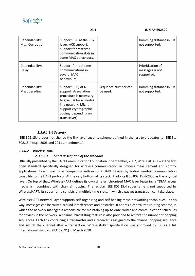
D3.1 JU GA# 692529
© The SafeCOP Consortium 78
Dependability: Msg. Corruption
Support CRC at the PHY layer; ACK support; Support for reserved communication slots in some MAC behaviours.
Hamming distance in IDs not supported.
Dependability: Delay
Support for real-time communications in several MAC behaviours.
Prioritization of messages is not supported.
Dependability: Masquerading
Support CRC; ACK support; Association procedure is necessary to give IDs for all nodes in a network. Might support cryptographic coding (depending on transceiver).
Sequence Number can be used.
Hamming distance in IDs not supported.
2.3.6.1.3.4 Security
IEEE 802.15.4e does not change the link-layer security scheme defined in the last two updates to IEEE Std
802.15.4 (e.g., 2006 and 2011 amendments).
2.3.6.2 WirelessHART
2.3.6.2.1 Short description of the standard
Officially presented by the HART Communication Foundation in September, 2007, WirelessHART was the first
open standard specifically designed for wireless communication in process measurement and control
applications. Its aim was to be compatible with existing HART devices by adding wireless communication
capability to the HART protocol. At the very bottom of its stack, it adopts IEEE 802.15.4-2006 as the physical
layer. On top of that, WirelessHART defines its own time-synchronized MAC layer featuring a TDMA access
mechanism combined with channel hopping. The regular IEEE 802.15.4 superframe is not supported by
WirelessHART. Its superframe consists of multiple time-slots, in which a packet transaction can take place.
WirelessHART network layer supports self-organizing and self-healing mesh networking techniques. In this
way, messages can be routed around interferences and obstacles. It adopts a centralized routing scheme, in
which the network manager is responsible for maintaining up-to-date routes and communication schedules
for devices in the network. A channel blacklisting feature is also provided to restrict the number of hopping
sequences. Each link containing a transmitter and a receiver is assigned to the channel hopping sequence
and switch the channel after a transaction. WirelessHART specification was approved by IEC as a full
international standard (IEC 62591) in March 2010.

D3.1 JU GA# 692529
© The SafeCOP Consortium 79
2.3.6.2.2 Experience of the standard at the different partners
The following experience on WirelessHART is available at the different partners:
● SINTEF:
○ SINTEF has extensive experience from evaluating, testing and piloting WirelessHART
systems and networks for the oil and gas industry in Norway, including laboratory
experiments and offshore installations. SINTEF has also been involved in technology
qualification of WirelessHART for operational use in Statoil.
○ SINTEF has experience with industrial WirelessHART products from Emerson and ABB.
○ SINTEF has access to the following development kits for WirelessHART: Softing (sensors),
Pepperl+Fuchs (industrial Gateway and Network Manager), Nivis (sensors, Gateway and
Network Manager)
2.3.6.2.3 Appropriateness of the standard with respect to the requirements of SafeCOP
2.3.6.2.3.1 Timeliness
In WirelessHART, time-division multiple access (TDMA) is used for channel access. The communication is
divided into distinct timeslots with a duration of 10ms. A collection of timeslots forms a superframe which
repeats in time throughout the entire lifetime of the network. The term frame is used to separate instances
in time of a specific superframe, as illustrated in Figure 2.3.1. One superframe must always be enabled,
although multiple superframes of variable lengths can coexist in a network. Superframes can be added and
removed while the network is operational.
Figure 2.3.1 Basic principle of TDMA
To supervise the communication within a network, two devices are typically assigned to a timeslot, one as a
source (transmitter) and the other as the destination (receiver). An exception to this is broadcast messages
where multiple devices are assigned as receivers in the same timeslot. Within a timeslot, the source device
may transmit a data packet to the destination device. Upon successful reception of a data packet, the
destination device will transmit an acknowledgment packet (ACK) to the source device, as depicted in Figure
2.3.2. If the source device fails to receive an ACK, the data packet will be retransmitted in the next available
timeslot. Note that an ACK is not transmitted upon reception of a broadcast message.
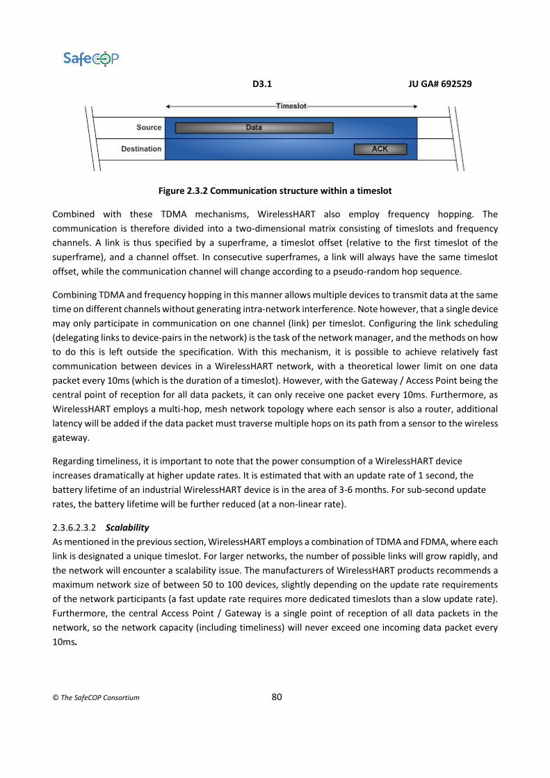
D3.1 JU GA# 692529
© The SafeCOP Consortium 80
Figure 2.3.2 Communication structure within a timeslot
Combined with these TDMA mechanisms, WirelessHART also employ frequency hopping. The
communication is therefore divided into a two-dimensional matrix consisting of timeslots and frequency
channels. A link is thus specified by a superframe, a timeslot offset (relative to the first timeslot of the
superframe), and a channel offset. In consecutive superframes, a link will always have the same timeslot
offset, while the communication channel will change according to a pseudo-random hop sequence.
Combining TDMA and frequency hopping in this manner allows multiple devices to transmit data at the same
time on different channels without generating intra-network interference. Note however, that a single device
may only participate in communication on one channel (link) per timeslot. Configuring the link scheduling
(delegating links to device-pairs in the network) is the task of the network manager, and the methods on how
to do this is left outside the specification. With this mechanism, it is possible to achieve relatively fast
communication between devices in a WirelessHART network, with a theoretical lower limit on one data
packet every 10ms (which is the duration of a timeslot). However, with the Gateway / Access Point being the
central point of reception for all data packets, it can only receive one packet every 10ms. Furthermore, as
WirelessHART employs a multi-hop, mesh network topology where each sensor is also a router, additional
latency will be added if the data packet must traverse multiple hops on its path from a sensor to the wireless
gateway.
Regarding timeliness, it is important to note that the power consumption of a WirelessHART device
increases dramatically at higher update rates. It is estimated that with an update rate of 1 second, the
battery lifetime of an industrial WirelessHART device is in the area of 3-6 months. For sub-second update
rates, the battery lifetime will be further reduced (at a non-linear rate).
2.3.6.2.3.2 Scalability
As mentioned in the previous section, WirelessHART employs a combination of TDMA and FDMA, where each
link is designated a unique timeslot. For larger networks, the number of possible links will grow rapidly, and
the network will encounter a scalability issue. The manufacturers of WirelessHART products recommends a
maximum network size of between 50 to 100 devices, slightly depending on the update rate requirements
of the network participants (a fast update rate requires more dedicated timeslots than a slow update rate).
Furthermore, the central Access Point / Gateway is a single point of reception of all data packets in the
network, so the network capacity (including timeliness) will never exceed one incoming data packet every
10ms.

D3.1 JU GA# 692529
© The SafeCOP Consortium 81
2.3.6.2.3.3 Safety
The WirelessHART Application Layer is limited to a predefined set of HART Commands, as defined by the
HART Field Communication Specification. For safety application where it is necessary with acknowledged
two-way communication between each safety entity, there are limitations in the availability of suitable
HART Commands for such an information exchange. So even though the network features of WirelessHART
should make it capable of addressing safety applications, the limited freedom of operation of the
Application Layer makes this difficult the achieve while maintaining compliance to the WirelessHART
specification. As a result, WirelessHART is not an ideal specification for the safety-related communication in
SafeCOP.
2.3.6.3 ISA100.11
2.3.6.3.1 Short description of the standard
The ISA100 standards committee of ISA aims to deliver a family of standards for wireless systems for
industrial automation. ISA100.11a was the first standard to emerge, being ratified in 2009 and updated in
2011. ISA100.11a is designed for secure and reliable wireless communication for non-critical monitoring and
control applications.
ISA100.11a is based on the IEEE Std. 802.15.4 PHY and MAC, but the MAC has been adopted to allow for
frequency hopping and extended security mechanisms. ISA100.11a only defines operation in the 2.4 GHz
band. TDMA with frequency hopping is used as the channel access mechanism. ISA100.11a supports both
routing and non-routing devices, so network topologies can be either star, star-mesh or full mesh depending
on the configuration and capabilities of the devices in the network.
An ISA100.11a network is able to carry multiple fieldbus protocols, such as Foundation Fieldbus, PROFIBUS
and HART. There is also integrated support for IPv6 traffic and routing in the network layer.
2.3.6.3.2 Experience of the standard at the different partners
The following experience on ISA100.11 is available at the different partners:
● SINTEF:
○ SINTEF has extensive experience from evaluating, testing and piloting ISA100.11a systems
and networks for the oil and gas industry in Norway, including laboratory experiments and
offshore installations. SINTEF has also been involved in technology qualification of
ISA100.11a for operational use in Statoil.
○ SINTEF has been involved in the development of the world's first wireless infrared
hydrocarbon gas detector, which uses ISA100.11a as a part of a SIL2 end-to-end safety
communication solution.
○ SINTEF has experience with industrial ISA100.11a products from Yokogawa.
○ SINTEF has access to the following development kits for ISA100.11a: Nivis (sensors,
Gateway and System Manager), Yokogawa (sensors, Access Point, Management Station).
D3.1 JU GA# 692529
© The SafeCOP Consortium 82
2.3.6.3.3 Appropriateness of the standard with respect to the requirements of SafeCOP
2.3.6.3.3.1 Timeliness
ISA100.11a employs TDMA and FDMA for medium access control, with a configurable timeslot duration
typically set at 10ms (see the section on "WirelessHART" for more information). Like WirelessHART,
configuring the link scheduling (delegating links to device-pairs in the network) is the task of the system
manager, and the methods on how to do this is left outside the specification. With this mechanism, it is
possible to achieve relatively fast communication between devices in an ISA100.11a network, with a
theoretical lower limit on one data packet every 10ms (which is the typical duration of a timeslot). However,
with the Gateway / Access Point being the central point of reception for all data packets, it can only receive
one packet every 10ms. Furthermore, as ISA100.11a typically employs a multi-hop, mesh network topology
where each sensor is also a router, additional latency will be added if the data packet must traverse multiple
hops on its path from a sensor to the wireless gateway.
For low latency applications, ISA100.11a has the flexibility to define a star-mesh network topology where e.g.
a safety sensor can function as an I/O-device with no routing functionality. It will then connect directly to the
wireless gateway, or to any other device with routing capability. This can enable a more deterministic
communication behaviour compared to the uncertainty of routing and paths in a full mesh network.
Regarding timeliness, it is important to note that the power consumption of an ISA100.11a device increases
dramatically at higher update rates. It is estimated that with an update rate of 1 second, the battery
lifetime of an industrial ISA100.11a device is in the area of around 12 months. For sub-second update rates,
the battery lifetime will be further reduced (at a non-linear rate).
2.3.6.3.3.2 Scalability
As mentioned in the previous section, ISA100.11a employs a combination of TDMA and FDMA, where each
link is designated a unique timeslot. For larger networks, the number of possible links will grow rapidly, and
the network will encounter a scalability issue. The manufacturers of ISA100.11a products recommends a
maximum network size of between 50 to 100 devices, slightly depending on the update rate requirements
of the network participants (a fast update rate requires more dedicated timeslots than a slow update rate).
For low latency applications that put a higher demand on the network, even smaller networks are
suggested, e.g. GasSecure (see section below) operates with a limitation of maximum 20 safety gas
detector per network.
2.3.6.3.3.3 Safety
The applicability of ISA100.11a for safety applications has been proven through the development of the GS01
wireless gas detector by GasSecure (now Dräger). It employs an end-to-end safety architecture, where a
safety communication layer has been added at the safety controller and each gas detector. This safety layer
handles the intermittent communication links as "black channels", which in theory can be any
communication protocol, as long as certain performance regarding packet error (PER) rates can be achieved.
The PER of the communication links must be known in order to calculate a proper strength and length of the
safety code (CRC).

D3.1 JU GA# 692529
© The SafeCOP Consortium 83
The GS01 has been certified as SIL2 by implementing PROFISafe on top of PROFINET at the field network
level, and by tunnelling PROFISafe over ISA100.11a over an ISA100.11a wireless network.
2.3.6.4 WIA-PA
2.3.6.4.1 Short description of the standard
WIA-PA is a specification for system architecture and communication protocol. It is built upon the IEEE
802.15.4 PHY and MAC. WIA-PA was developed by the Chinese Industrial Wireless Alliance (CIWA) under the
requirements of the process automation industries. WIA-PA became a Public Available Specification (PAS) of
IEC via IEC voting on October 31, 2008 with number IEC/PAS 62601.
The WIA-PA network topology is formed using cluster heads as essential device types. Each cluster head
forms a local star network. Only devices belonging to the specific cluster head can become cluster members.
The cluster members are typically field devices, i.e. sensors and actuators. Field devices are solely
input/output devices, with no routing capability. As a consequence, network topology is limited to a star-
mesh configuration. Redundancy is achieved at the cluster heads, by adding a redundant cluster heads. In
this manner, the local star network as a whole benefits from redundancy. However, there is no alternative
route for broken links from field device to the cluster head.
2.3.6.4.2 Experience of the standard at the different partners
The following experience on WIA-PA is available at the different partners:
● SINTEF:
○ SINTEF has a theoretical knowledge of the WIA-PA specification, but does not have any
practical experience, as WIA-PA products have limited availability outside of China (at the
time of writing).
2.3.6.4.3 Appropriateness of the standard with respect to the requirements of SafeCOP
2.3.6.4.3.1 Timeliness
WIA-PA employs TDMA and either a static channel or frequency hopping for medium access control, with a
configurable timeslot duration typically set at 10ms (see the section on "WirelessHART" for more
information). WIA-PA is fixed in a star-mesh network topology, where the sensors do not have routing
capability. For low latency applications, this configuration is ideal, with the drawback being a potential lack
in robustness and reliability due to the reliance on a single link between the sensor and cluster head.
Like WirelessHART, configuring the link scheduling (delegating links to device-pairs in the network) is the
task of the system manager, and the methods on how to do this is left outside the specification. With this
mechanism, it is possible to achieve relatively fast communication between devices in a WIA-PA network,
with a theoretical lower limit on one data packet every 10ms (which is the typical duration of a timeslot).
However, with the Gateway / Access Point being the central point of reception for all data packets, it can
only receive one packet every 10ms.

D3.1 JU GA# 692529
© The SafeCOP Consortium 84
2.3.6.4.3.2 Scalability
As mentioned in the previous section, WIA-PA employs a combination of TDMA and FDMA, where each link
is designated a unique timeslot. For larger networks, the number of possible links will grow rapidly, and the
network will encounter a scalability issue. Even though each cluster tree can operate somewhat
independently with a relatively large number of connected sensors, the congestion will be at the
communication between cluster heads and the central gateway. It is expected that the network size for low
latency applications will be similar to the limitations found for WirelessHART and ISA100.11a, i.e. in the area
of 20-100 sensors per network.
2.3.6.4.3.3 Safety
As mentioned in the previous to sections, the timeliness and scalability features of the WIA-PA should support
small networks for applications requiring low latency. In addition, the structure of the WIA-PA application
layer is generic enough to enable tunnelling and transmission of safety related information, e.g. PROFISafe.
The main drawback with WIA-PA is the limited availability of products outside China. It is therefore not
suggested to further pursue WIA-PA as a communication protocol for SafeCOP.
2.3.6.5 DASH7
2.3.6.5.1 Short description of the standard
Contrary to other existing low-power wireless technologies, D7AM defines all the layers of the OSI (Open
Source Interconnect) model, from the physical layer up to the application layer. The goal of D7AM is to handle
bursty, light data and asynchronous and transient usage models. This approach is referred to as BLAST
(bursty, light, asynchronous, stealth and transitive), and this means that it is tuned for dealing with inherently
mobile devices that need to upload small bits of information reliably thanks to its range, low-power and
robustness features.
Regarding the data-link layer, D7AM supports both synchronous and asynchronous communication models.
To support both communication models, the data-link layer is based on two well-known techniques:
preamble sampling (PS) and carrier sense multiple access (CSMA). In addition, all motes in the network share
a common knowledge of time, the tick, which is the smallest amount of time at which events at the MAC
layer can be resolved. However, there is no global network synchronization, as each clock may tick at a
different rate, e.g., due to temperature drift for instance. Nevertheless, it is important to take into account
that D7AM operation does not have the same stringent requirements as TSCH because time synchronization
is ad hoc. That is, synchronization happens every time a network event is triggered and only needs to be
maintained for the duration of such an event, which typically represents a smaller interval than clock drifts
relative to each other.
Using PS, a node can trigger communications with another node or a group of nodes asynchronously. Nodes
execute the channel scan series, which is an ordered list of time events at which nodes wake up and turn on
the radio to receive a background frame. In order to trigger communications, the standard defines a beacon
transmit series, which consists of an ordered list of time events at which the node is expected to wake up
and turn on the radio to transmit a background frame. These include information regarding the time that the
node is expected to wake up and the channel that it has to listen to. Both the channel scan series and the

D3.1 JU GA# 692529
© The SafeCOP Consortium 85
background scan series can be configured depending on the application requirements, e.g., to minimize
latency or maximize battery duration.
The main difference between D7AM and other existing technologies is the query system implemented at the
upper layers of the stack, which is highly integrated with the lowest layers. The query system enables to
restrain the response of nodes to a query based on a set of upper layer parameters. For example, during
synchronization, the initiating node may indicate that the query is only for nodes that have a temperature
sensor. Therefore, all the nodes that do not have a temperature sensor will not synchronize and attempt to
reply to the subsequent queries.
2.3.6.6 IEEE 802.15.5
2.3.6.6.1 Short description of the standard
The IEEE 802.15.5 Task Group aims at enabling mesh capability for high-rate and low-rate Wireless Personal
Area Networks. The IEEE 802.15.4 does not specify how to support multi-hop routing abilities, delegating the
design and development of them to the upper layers. The objective of IEEE 802.15.5 is therefore to solve the
limitations of IEEE 802.15.4, developing basic mesh networking functions and primitives. With this aim, IEEE
802.15.5 provides features such as node discovery, multicast, reliable broadcast, synchronized and
unsynchronized operations, power saving (ON/OFF scheduling strategy), and route tracing, thus taking into
account the strict constraints of the WSN devices. The result is a recommendation, known as the LR-WPAN
mesh standard, which enables a migration from IEEE 802.15.4 to mesh networks.
In order to address energy efficiency, the standard proposes two strategies. In Asynchronous Energy Saving
(AES) it carries out communications in a mesh topology by using a contention-based algorithm, where each
station transmits data only when the physical medium is idle. As a result, the information may reach its
destination suffering high delay variability and achieving low transmission rates.
For supporting stricter timing and lower power requirements than those provided by the AES solution, an
alternative method is proposed. The synchronous communication mechanism called Synchronous Energy
Saving (SES) uses a strict schedule of tasks for all network devices which are synchronized to a unique node,
the mesh coordinator, mainly on static networks. The mesh coordinator is the head device of the tree
topology and it is in charge of starting the synchronization process by sending a message with its clock time
information twice. Each node of the network, child of the mesh coordinator, stores the clock time of the first
message sent by the coordinator and a timestamp (temporal label included in the message header) with its
own clock time. When the second message arrives at the children nodes, they calculate the difference
between both coordinator clock times and the difference between their own current clock and the
timestamp previously stored. The difference between both resulting values is the drift between each one of
the children and the coordinator. If all nodes on the network are not reached by the message of the
coordinator in one-hop, these children retransmit the coordinator’s clock times in multiple hops to the rest
of network nodes, spreading the synchronization along the logical tree.
At the same time as the first synchronization action is spreading, the SES mechanism divides the entire mesh
network into multiple fixed regions, so that some nodes become parents of each one of these regions. Placed
between two regions, the parent nodes are border devices in charge of guaranteeing the global

D3.1 JU GA# 692529
© The SafeCOP Consortium 86
synchronization of the entire mesh network. To achieve this purpose, parent nodes are able to perform a
twofold task simultaneously: (i) to be synchronized with the up-region and (ii) to be responsible for
synchronizing all the children nodes of its own region in one or multiple-hops. This is the reason why these
special nodes (parents) are denoted as Region Synchronizers. The goal is to share the network-wide
synchronization responsibility between the mesh coordinator and the synchronizers of each region for future
synchronization actions. In this context, each one of these actions is triggered by the mesh coordinator, which
synchronizes all the nodes of the first region by means of a synchronization request message, ending its
operation when the synchronization reply message arrives from the most remote node of the first region.
Once the time assigned by the mesh coordinator for the synchronization of the first region expires,
synchronizers belonging to the second region start the same procedure again and so on with the rest of
regions.
2.3.6.6.2 Appropriateness of the standard with respect to the requirements of SafeCOP
2.3.6.6.2.1 Timeliness
The timeliness property of this protocol makes it more suitable for use cases such as 3 and 4.
The exclusive features of IEEE 802.15.5 include
● Multiple beacon operation: in which the whole network is time-slotted through multiple beacons
and will guarantee deadlines
● distributed medium access: Guaranteed bandwidth for transmissions can be provided which
increases the reliability of the network.
● Frequency Reuse: Usage of some extra bandwidth to accommodate more nodes.
● Topology independent: supports mesh and cluster tree networks, this can help in integrating
routing protocols and eventually increasing overall quality of service.
2.3.6.6.2.2 Safety
The standard uses a distributed reservation protocol under which scheduled transmissions through
beacons can be carried out. The medium is reserved by transmitter and also the receiver. When a set of
nodes occupy the medium it is announced through a beacon so that the Neighbours are aware of
transmissions. This eliminates the hidden node problem. Whereas the exposed node problem still remains
as the medium is blocked in a larger area and the capacity degrades with more number of nodes.
3 Discussion Here it is expected to suggest standards and carry out a discussion of the appropriateness of those
standards to each use case, pointing out what is lacking, identifying eventual extensions, pros and cons.
Analyse the adequacy concerning a set of safety related properties
D3.1 JU GA# 692529
© The SafeCOP Consortium 87
Design methodology
In this section we propose a methodology for correctly choosing a wireless standard to support a safe and
secure wireless CPS system, in regards to wireless communications. As mentioned in DEWI_D_311.006-1,
and in section 1 of this deliverable, it is recommended to rely on existing Functional Safety standards as
much as possible, to carry out an effective system development in respect to safety. This is mostly due to
the fact these standards have been proven numerous times and hence are quite valuable in each
application area. Therefore, this process begins with the selection of an appropriate Functional Safety
standard, relevant to the application area. Since, wireless communications present a different and unique
set of challenges, we follow DEWI project proposal of adding an additional risk reduction block concerning
wireless communications. The process is as follows:
1. Chose appropriate Functional Safety Standard (IEC 61508, ISO 26262, EN 50128, DO-178C, other...)
2. Add an additional risk reduction measures for wireless communications involving specification and
realization.
3. Carry out a hazard and risk analysis according to standard focusing on wireless communications.
a. List requirements on wireless communications (Performance, dependability/safety and
security)
b. Chose a wireless communication standard
c. Check performance aspects in regards to system requirements (scalability, delay, energy-
efficiency)
d. Check safety aspects (does it provide the necessary defence mechanisms?)
e. Check security aspects
4. Validate choice and propose additional defence mechanisms to be implemented if needed.
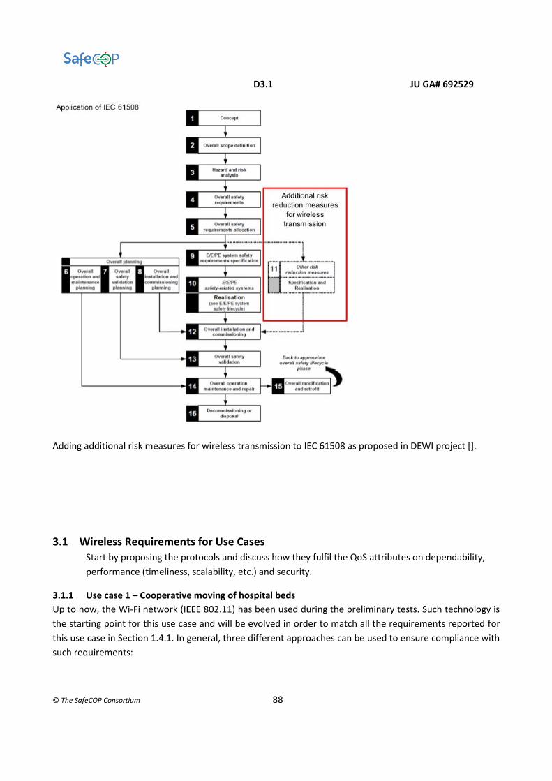
D3.1 JU GA# 692529
© The SafeCOP Consortium 88
Adding additional risk measures for wireless transmission to IEC 61508 as proposed in DEWI project [].
3.1 Wireless Requirements for Use Cases
Start by proposing the protocols and discuss how they fulfil the QoS attributes on dependability,
performance (timeliness, scalability, etc.) and security.
3.1.1 Use case 1 – Cooperative moving of hospital beds
Up to now, the Wi-Fi network (IEEE 802.11) has been used during the preliminary tests. Such technology is
the starting point for this use case and will be evolved in order to match all the requirements reported for
this use case in Section 1.4.1. In general, three different approaches can be used to ensure compliance with
such requirements:

D3.1 JU GA# 692529
© The SafeCOP Consortium 89
1. Wireless technology. Requirements addressed directly by the selected wireless technology (in its
actual status or evolving it with new ad-hoc features).
2. Redundancy. Requirements addressed by an external redundancy, typically adding another
communication channel between source and destination.
3. Upper layers. Requirements addressed by upper layers (e.g. application layer) of the system
architecture.
A single requirement could be addressed by one, two or all the approaches listed above. Table 1 represents
a quick overview of the requirements and the selected approaches to address them. If the actual standard is
not sufficient for a requirement and a modification/improvement is needed, such requirement is marked as
missing [-].
# Requirement Approach to match the requirement
MLC to MLC Cameras (external sensors) to
MLC
#1 Connection establishment delay Wireless technology [-] Wireless technology [-]
#2 Delay Wireless technology [-] Wireless technology [-]
#3 Communication quality Upper layers Upper layers
#4 Detect quality degradation Upper layers Upper layers
#5 Communication loss Redundancy, Upper layers Upper layers
#6 Detect communication loss Upper layers Upper layers
#7 Multiple connections N.A. Wireless technology
#8 Communication range N.A. Wireless technology
#9 Data security and encryption Upper layers Upper layers
Table 1: communication requirements and approaches to ensure compliance with them
The first two requirements need an evolution of the current available standard. As a matter of fact, real-time
communication needs a limitation to the connection (re)establishment delay (#1) and to the latency/delay in

D3.1 JU GA# 692529
© The SafeCOP Consortium 90
the communication (#2). Currently no boundaries are assured by the adopted technology (i.e. the 802.11)
and consequently an extension is needed. These considerations are true for both connections (MLC to MLC
and Cameras/external sensors to MLC).
The wireless 802.11 channel quality (#3) is directly related to the power of the received signal, namely
Received Signal Strength Indicator (RSSI). This parameter is also responsible for communication loss (#5), if
its value is below a certain threshold. To guarantee such requirements no standards extensions are needed
but they must be correctly addressed in the design time, by imposing that the RSSI must be over a minimum
threshold to have a satisfactory link quality and in order to avoid communication loss. It is worth noticing
that in the implementation phase it is not difficult to properly install the wireless access points in order to
cover all the area with and adequate level of RSSI. After that, the Runtime Manager will be in charge to
monitor if this condition is respected when the robots are moving the beds. Moreover in this way the Runtime
Manager is also the logical entity which monitors the status of the connectivity and consequently detect if
there are communication quality degradation (#4) and communication loss (#6). As a consequence such
requirements are constantly monitored by the Runtime Manager, whose architecture, functionalities and
characteristics are out of the scope of this document. Nevertheless it is also important to highlight that such
requirements are not guaranteed directly by the adopted wireless technology but their compliance is ensured
by a higher level in the architecture (e.g. the application layer), where are implemented the RM
functionalities.
A further solution could be adopted to face the communication loss problem: redundancy could be useful
for those links which are critical for the system safety. For example the communication between two MLCs
is crucial to coordinate their movements together, piloting correctly the bed. If this communication is
interrupted the robots cannot move. On contrary if a cameras or another type of external sensor, cannot
communicate with the MLCs they could continue their navigation using only their on board sensors and
taking some precautions, maybe reducing their speed. Safety is still guaranteed even if in a lower mode,
called “safety degraded mode”.
Multiple connections support and communication range (#7 and #8) are two requirements relevant only for
the Cameras to MLC communication. Instead the two MLCs of a single bed are installed at a fixed distance
and communicated in a point to point fashion. Consequently range and scalability are not relevant. In any
case the compliance with such requirements, for the interconnection between MLC and multiple cameras
also simultaneously, is already ensured by the adopted standard, 802.11, which support the multi-
connectivity and a sufficient communication range for the indoor scenario considered in this use case.
Both communications considered have to be secure, as previously reported (#9). This requirement is
guaranteed acting not directly on the wireless technology but in the upper layers. As a matter of fact, info
exchange using wireless channel can be encrypted using appropriated protection system, according to the
desired level of cyber-security. In this way data integrity is guaranteed, allowing access to the data only to
authorized elements.

D3.1 JU GA# 692529
© The SafeCOP Consortium 91
3.1.2 Use case 2 – Cooperative bathymetry with autonomous boat platoons
There are three wireless communication channels utilized in UC2 including one implemented based on the
open source VHF protocol, NGHam developed by MR. However, The following discussion is solely based on
the NGHam channel.
There are some implementation requirements related to wireless communication between the VCS and
USVs.
● Communication loss
Communication loss can be detected if one of the connected system has not received the update message
from another connected system within a time limit. This scheme is independent from the NGHam protocol.
● Communication range
The minimum distances between the manned vessel where the VCS is located and USV can be 10-20 m.
The maximum distance between the manned vessel where the VCS is located and USV can be up to 10 km
(e.g. during transit). As the communication range impacts the signal strength, we need to evaluate the
optimal communication range with the consideration of quality of service requirements.
● Channel redundancy
There are three communication channels between the VCS and the USV, i.e., via e.g. a 3G/4G/GPRS mobile
broadband, via Owl VHF which implements NGHam protocol, and via IP Radio. Only one channel is being
used for controlling the USV, but multiple channels could be connected for switching over once the used
channel is lost. Channel switching over is manually done by the operator.
● Scalability
Theoretically, it is possible to connect unlimited number of USV(s) to a VCS according to NGHam. However,
as the number of USV(s) connected to a VCS increases, the overall performance such as packet delay,
throughput and packet loss may be degraded accordingly. Therefore, depending on the MAC scheme
implemented (TDMA is used in UC2), we have to evaluate the maximum number of USVs can be connected
to the VCS.
● Timeliness
The TDMA scheme is used to decide when the VCS and each USV can access the NGHam channel and
transmit data. How to ensure the timeliness of each type of data depends on the proper configuration of
the time slot size. In order to achieve the timeliness of different types of data, some performance analysis
has to be conducted based on the number of nodes (both the VCS and USVs) connected, the operation
mode of the USV, the types of data transmitted, and the amount of traffic transmitted. This performance
analysis will be one task of WP3 and carried out by DNV GL.
● Security
The NGHam protocol does not specify any authentication scheme. Therefore the USV is not authenticated
when it communicates with the VSC. The NGHam uses Reed Solomon FEC to ensure a certain level of
message integrity during transmission. However, it may not be sufficient if the end devices which

D3.1 JU GA# 692529
© The SafeCOP Consortium 92
transmit/receive data are not authenticated and do not incorporate any security mechanism. The packet
format of NGHam does not specify the field for sequence number. Thus, it is difficult to detect packet loss.
In addition, it would be difficult to reassemble a stream of data in its original form if a data packet is
segmented into more than one NGHam packets during transmission.
3.1.3 Use case 3 – Vehicle control loss warning
Candidate wireless communication protocols
The UC requirements suggest the utilization of two standards, the IEEE 802.11p (UC3008) and IEEE
802.15.4e (UC3009) for inter and intra-vehicle communications respectively. In what follows, we analyse
how these protocols can cope with the particular UC requirements.
Performance Attributes
Timeliness
Although IEEE 802.15.4e in some MAC behaviours can cope with real-time communications, as specified in
UC3011, the IEEE 802.11p communication standard does not provide this kind of support. Timeliness is of
the utmost importance in UC3. It is needed, for instance to guarantee the Control Loss Warning message
has a bound on its latency. Without it, it is not possible to guarantee all the vehicles will receive this
emergency message on time. The same applies for maintaining the platoon under control. The absence of
bounds in message transmission time will result in an unpredictable behaviour of the platooning
application.
This will also support the keep alive mechanism mentioned in UC3010. Without a bound in the keep alive
message, it is impossible to react in time to a sudden loss of communication.
Scalability
Regarding scalability, UC3012 specifies that 10 nodes should be supported in the application. This is not to
say that a higher number of wireless sources will not be operating in the vicinity. Interference is connected
to resilience that is handled by UC3013. This will be analysed later. The scalability requirement presents a
major impact on routing. Most probably, the organization of the vehicles in a straight line (platoon) will
impose the existence of a routing mechanism to reach the vehicles from one end to the other end of the
platoon. Again, this is expected to be carried out within a known time bound.
Dependability
For a communication system to be considered safe, at least one defence mechanism against each message
error (Section 1.3.1) must be in place. The defence mechanisms support for each message threat is
summarized in the table below for IEEE802.15.4e (intra-vehicle communications) and IEEE 802.11p (inter-
vehicle communications).
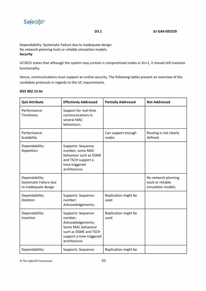
D3.1 JU GA# 692529
© The SafeCOP Consortium 93
Dependability: Systematic Failure due to inadequate design No network planning tools or reliable simulation models. Security
UC3015 states that although the system may contain n compromised nodes in 3n+1, it should still maintain
functionality.
Hence, communications must support an online security. The following tables present an overview of the
candidate protocols in regards to the UC requirements.
IEEE 802.15.4e
QoS Attribute Effectively Addressed Partially Addressed Not Addressed
Performance: Timeliness
Support for real-time communications in several MAC behaviours.
Performance: Scalability
Can support enough nodes.
Routing is not clearly defined.
Dependability: Repetition
Supports: Sequence number; some MAC behaviour such as DSME and TSCH support a time-triggered architecture.
Dependability: Systematic Failure due to inadequate design
No network planning tools or reliable simulation models.
Dependability: Deletion
Supports: Sequence number; Acknowledgements;
Replication might be used
Dependability: Insertion
Supports: Sequence number; Acknowledgements; Some MAC behaviour such as DSME and TSCH support a time-triggered architecture.
Replication might be used
Dependability: Supports: Sequence Replication might be
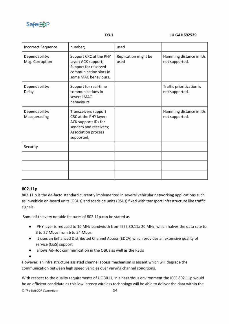
D3.1 JU GA# 692529
© The SafeCOP Consortium 94
Incorrect Sequence number; used
Dependability: Msg. Corruption
Support CRC at the PHY layer; ACK support; Support for reserved communication slots in some MAC behaviours.
Replication might be used
Hamming distance in IDs not supported.
Dependability: Delay
Support for real-time communications in several MAC behaviours.
Traffic prioritization is not supported.
Dependability: Masquerading
Transceivers support CRC at the PHY layer; ACK support; IDs for senders and receivers; Association process supported;
Hamming distance in IDs not supported.
Security
802.11p
802.11 p is the de-facto standard currently implemented in several vehicular networking applications such
as in-vehicle on-board units (OBUs) and roadside units (RSUs) fixed with transport infrastructure like traffic
signals.
Some of the very notable features of 802.11p can be stated as
● PHY layer is reduced to 10 MHz bandwidth from IEEE 80.11a 20 MHz, which halves the data rate to
3 to 27 Mbps from 6 to 54 Mbps.
● It uses an Enhanced Distributed Channel Access (EDCA) which provides an extensive quality of
service (QoS) support
● allows Ad-Hoc communication in the OBUs as well as the RSUs
●
However, an infra structure assisted channel access mechanism is absent which will degrade the
communication between high speed vehicles over varying channel conditions.
With respect to the quality requirements of UC 3011, in a hazardous environment the IEEE 802.11p would
be an efficient candidate as this low latency wireless technology will be able to deliver the data within the

D3.1 JU GA# 692529
© The SafeCOP Consortium 95
specific time critical window. Whereas, uncoordinated medium access mechanism and mobility factors will
result in the degradation of the system performance.
It is currently in deployment in the Portuguese city of Porto, where, it is used as a mesh to provide vehicular
data between public vehicles and WiFi access for its passengers.
QoS Attribute Effectively Addressed Partially Addressed Not Addressed
Performance:
Timeliness
Supports real-time
communication if mobility
parameters are not involved.
better access
mechanisms
are to be yet
defined
Performance:
Scalability
Can support enough nodes. Routing is not
clearly defined.
Dependability:
Repetition
Simulations in literature shows that
it can support very high priority
traffic and provide lesser delays
Dependability:
Systematic
Failure due to
inadequate
design
Access
mechanisms
better than
EDCA must be
explored
Dependability:
Deletion
Dependability:
Insertion
Supports a complete mesh network Replication might be used
Dependability:
Incorrect
Sequence
Dependability:
Msg. Corruption
Support CRC at the PHY layer; ACK
support
Replication might be used Lesser chances
for message
corruption
Dependability:
Delay
Traffic prioritization is supported

D3.1 JU GA# 692529
© The SafeCOP Consortium 96
Dependability:
Masquerading
Transceivers support CRC at the
PHY layer; ACK support; IDs for
senders and receivers; Association
process supported;
Hamming
distance in IDs
not supported.
Security Does not specify the
security layer, The PHY
layer is specially coped up
to avoid any signal echoes
Encryption
techniques can
be developed
3.1.4 Use case 4 – Vehicles and roadside units interaction
3.1.5 Use case 5 – V2I cooperation for traffic management
Traffic management requires the cooperation among a continuously changing set of heterogeneous devices,
connected via wireless and/or broadband mobile connections. Such devices include traffic lights, possibly
enhanced with sensors (cameras, but also environmental monitoring sensors), and on-board units installed
on vehicles. The goals of traffic management is to reduce accidents, decrease traffic, and decrease fuel waste.
While VANET (IEEE 802.11p) solutions are gaining ground, many on-board units are only equipped with 3G/4G
mobile connectivity. From a communication point of view, the goal of the Use Case is to guarantee that
information is gathered from sensors (both on-board and road-side), possibly pre-elaborated locally,
transmitted to the remote Control Centre, where a traffic management decision and/or hazard detection is
performed, and the decision or alert is notified back to the actuators (traffic lights and on-board units) within
a time limit that still allows the notification to be of use for the drivers.
Furthermore, since the on-board actors change rapidly, it is necessary to ensure the trustworthiness of these
actors, which may lead to additional overheads for authentication and/or handover procedures.
The following requirements have been identified to drive the definition of the SafeCOP communication
infrastructure:
● UC5001 WSN IEEE 802.15.4 protocol support
● UC5002 Cryptographic Scheme – Authentication
● UC5003 Cryptographic Scheme – Confidentiality
● UC5004 Cryptographic Scheme – Integrity
● UC5006 WSN Loss of communications
● UC5007 Available bandwidth
● UC5013 Prediction of anomalies (e.g., congestion, cyber-attacks) through machine learning
● UC5024 Communication channel redundancy
● UC5025 Communication loss detection
● UC5026 Communication degradation detection
● UC5029 Communication encryption
● UC5030 3G/4G communication

D3.1 JU GA# 692529
© The SafeCOP Consortium 97
● UC5031 IEEE 802.11p communication
It is worth noting that channel redundancy can be achieved by supporting both IEEE 802.11p and 3G/4G, with
degraded performance on the latter, whereas IEEE 802.15.4 is to be employed for road-side satellite sensors
(e.g., additional cameras to avoid blind spots, or ice detection sensors embedded in the road pavement).
Safety requirements on the communication infrastructure are also imposed, as the system needs to be able
to predict and detect anomalies, in particular loss of communication or degraded communication. Finally,
communications among the actors of the systems should be protected from unauthorized access, ensuring
integrity, confidentiality and authenticity.
3.1.6 Use case 6 – 5G V2X Cooperative Communications
A detailed Automated driving use case within 3GPP Rel.15 [3GPP, Rel.15] can be found with the title
“Cooperative Short Distance Grouping (CoSdG)” that refers to the use case, where the distance between
vehicles such as trucks are extremely small – creating a desirable form of legal tailgating. The gap distance
translated to time can equivalently be as low as 0.3s or even shorter, which at 80km/h leads to almost 6.7m
distance between the vehicles. Driving such closely is made possible by advanced automated cooperative
driving technology, in combination with a highly reliable wireless vehicle-to-vehicle (V2V) communication
system that enables data transmission with low latency. 5G CoSdG is different from current platooning
since the CoSdG envisions closer spacing and lower latency that what can reliably accomplished with
alternative technologies. CoSdG would therefore make a remarkable improvement in string stability,
efficiency, and ultimately safety. 5G CoSdG enables direct control intervention, where messages must be
transmitted reliably and delivered with very low latency. The jitter must be extremely low, as the electronic
control unit operates usually on data provided periodically. Multiple vehicles must be associated to the
leading vehicle using the wireless connection. We can assume that the number of vehicles can exceed
10,000 vehicles in scenarios with multiple lanes and multiple levels and types of roads. Fig.3 conceptualizes
the CoSdG, where the join/leave, sting stability, warning messages and lead vehicle features are retained.
Figure-F3: The 5G Cooperative Short Distance Grouping (CoSdG) use case

D3.1 JU GA# 692529
© The SafeCOP Consortium 98
A list of the most important design requirements for the 5G 3GPP system can be found below [3GPP,
Rel.15]:
● to control the communication range for a message based on the characteristic of the messages
transmitted by a UE supporting V2X application.
● to support in a periodic manner at least 30 message per second broadcast by a UE supporting V2X
application.
● to create/destroy a group for UEs supporting V2X application.
● to support up to 5 UEs for a group of UEs supporting V2X application.
● to add/remove a UE supporting V2X application into a group of UEs supporting V2X application.
● to support 10 ms end-to-end latency for message transfer among a group of UEs supporting V2X
application.
● to support [90] % reliability.
● to support triggered and periodic transmission of small data packets (e.g. 300-400 bytes).
Future Research Directions
Use case 1 – Cooperative moving of hospital beds
Fig.F1 below depicts the CPS architecture proposed for the cooperative communication and control based
on the discussion above. It consists of the following building blocks:
● The state estimation that is supervised using human supervision or through radio communication.
In both cases, a particular CPS profile is built into or received by the robot respectively.
● The state estimation communications to the path routing that calculates the routing directions or
the gap control features, which takes input also from the control policy.
● The coordination plane is built on top of the communication and control infrastructure providing
the required cooperative (i.e. distributed) communication and control protocol.
Our aim for the SafeCop project is to build a cooperative communication and control solution that is a type
of distributed control protocol. The cooperation should be retained with high reliability and low latency.
The corresponding communication protocol and control functionalities need to be investigated and
developed for the next WP3 deliverables and year of the project. In particular, we plan to develop the
followings:
● A context awareness messages (CAM) protocol, where the context will be provided by particular
states specified for particular cooperative manoeuvres.
● Distributed control features development to provide the cooperative control for particular
cooperative manoeuvres.
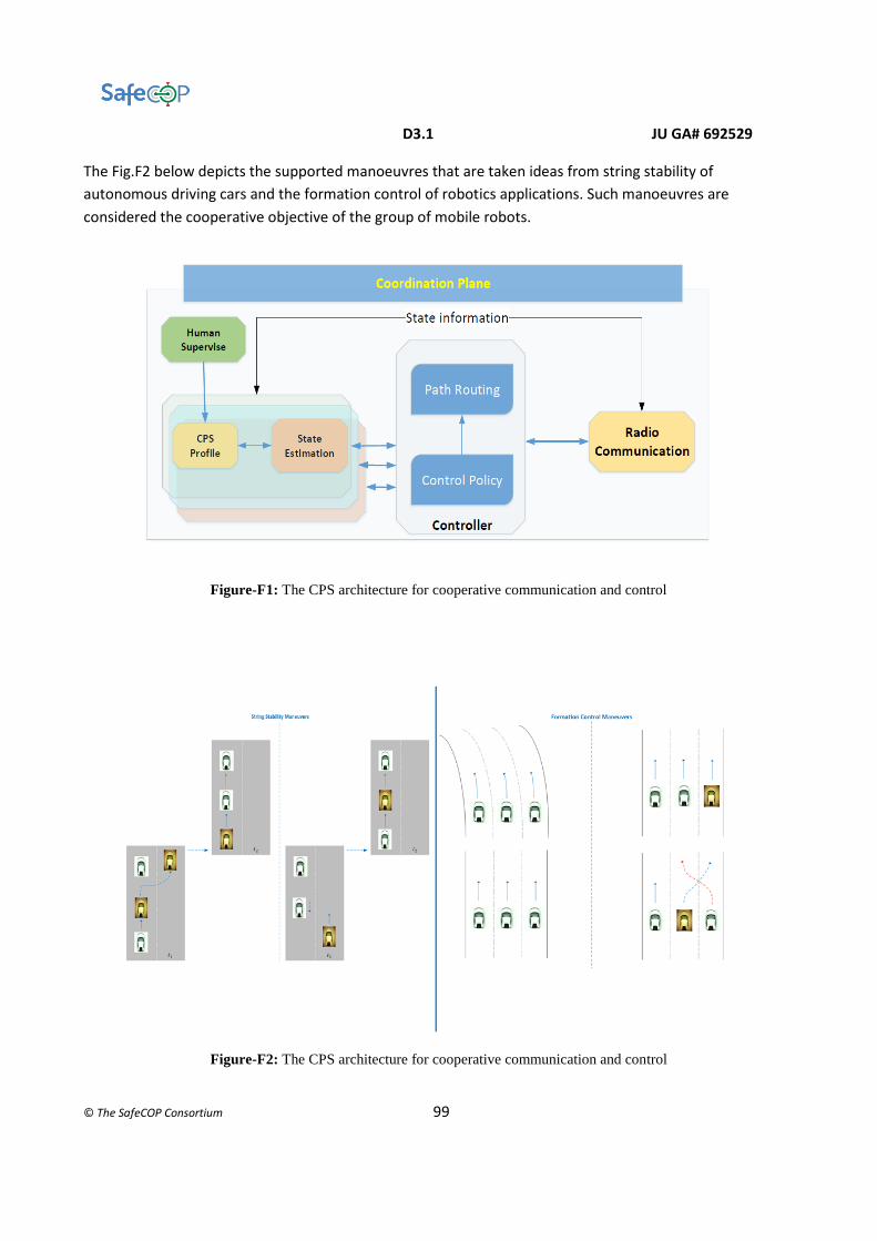
D3.1 JU GA# 692529
© The SafeCOP Consortium 99
The Fig.F2 below depicts the supported manoeuvres that are taken ideas from string stability of
autonomous driving cars and the formation control of robotics applications. Such manoeuvres are
considered the cooperative objective of the group of mobile robots.
Figure-F1: The CPS architecture for cooperative communication and control
Figure-F2: The CPS architecture for cooperative communication and control

D3.1 JU GA# 692529
© The SafeCOP Consortium 100
Use case 2 – Cooperative bathymetry with autonomous boat platoons
Maritime regulations - IMO requirement related to communication (ship-ship/ship-shore)
As unmanned, autonomous ships represent the future of the maritime industry, the relevant stakeholders of
maritime sector have to be involved in the development and operation of autonomous. Particularly, as the
global regulatory body for international shipping, the International Maritime Organization (IMO) needs to
develop new regulatory framework in order to ensure the safety, security and environmental performance
for the future automated global shipping industry. As advances in information and communications
technology and robotics will accelerate changes in the way ships are operated, the IMO has to incorporate
the usage of these advanced technologies into its regulatory framework.
The IMO developed the Global Maritime Distress and Safety System (GMDSS) to provide the communication
support needed to implement the search and rescue plan. The GMDSS enables a ship in distress to send an
alert using various radio systems. In 1988, IMO amended the Safety of Life at Sea (SOLARS) Convention,
requiring ships subject to it fit GMDSS equipment. SOLARS is an international maritime treaty which requires
Signatory flag states to ensure that ships flagged by them comply with minimum safety standards in
construction, equipment and operation. Chapter IV of SOLARS is about radio communications. This chapter
incorporates the GMDSS and requires passenger and cargo ships of 300 gross tonnage and upwards on
international voyages to carry radio equipment, including satellite Emergency Position Indicating Radio
Beacons (EPIRBs) and Search and Rescue Transponders (SARTs) for the location of the ship or survival craft.
GMDSS telecommunications equipment should not be reserved for emergency use only. The IMO encourages
mariner to use GMDSS equipment for routine as well as safety telecommunications.
IMO has not developed any explicit regulations related to wireless communication for autonomous ships. In
UC2, we will define requirements of safely and securely communicating between (unmanned) ships based
on the safety analysis and security analysis of the cooperative system. The results produced from UC2 WP3
may provide some input to help IMO develop new regulations to deal with the safety and security issues of
communications between unmanned ships.
Use case 3 – Vehicle control loss warning
The standards we have taken for the implementation of UC3 are IEEE 802.15.4e and IEEE 802.11p. Both of these standards have the necessary features to be implemented in both inter and intra car communication. IEEE 802.15.4e: The standard though it provides time critical MAC behaviours suitable to support inter car communication, it lacks network planning and the worst case bounds that will help the end developer to have predominant idea about the system. Mathematical methods, for example: using network calculus can be used to implement network models for the system as a whole. Some of the MAC behaviours like DSME that supports a large number of nodes do not have any simulation models for further implementation. Research work can be carried on in this direction to further explore the possibilities of this standards implementation. A cross layer protocol can be implemented using the RPL and scalability supporting MAC layers like DSME. This can help in building a protocol stack that will meet critical deadlines and at the same time not compromising the reliability and scalability aspects.

D3.1 JU GA# 692529
© The SafeCOP Consortium 101
Much work has not been carried out on LLDN in the literature. LLDN supports retransmission uplink that boost the overall reliability of the network. An analytical work has been carried out to make LLDN support multi-channel access. Implementation of such enhanced MAC behaviours can also be effective for our use case. IEEE 802.11p: Despite being a de-facto standard for vehicular communication, this standard has some room for improvement. The standard provides a high reliability by its unique physical layer which has been verified in real-time scenarios. The MAC layer of the standard however, supports uncoordinated medium access mechanism. A MAC layer that supports guaranteed transmission and preferably time constrained MAC layer can be studied and developed for IEEE 802.11p to increase its performance and reliability. Similar to the previously proposed network analysing method, IEEE 802.11p also can be studied using analytical methods to have a reliable quality of service bounds for the overall network.
Use case: Cooperative Mobile Robots
3.2 Use case: 5G Cooperative Short Distance Grouping (CoSdG) use case
Details on the technical challenges (that should be addressed) to provide the 5G CoSdG use case can be
found below. A decentralized solution based on direct communications (dCom) with low latency and high
reliability should be provided with the following features:
● To design the PC5 interface to realize direct information exchange between UEs.
● To provide direct communication is either in-coverage or out-of-coverage.
● Out-of-coverage UEs can become synchronization sources and deliver synchronization
sequences for neighbouring out-of-coverage UEs to synchronize with them.
Group-based direct communication in addition to the other features must be provided:
● All UEs belong to at least one authorized ProSe group.
● The transmitter UE can only deliver data to one destination group in one SA (Scheduling
Assignment) period.
● The SA period can be as long as 40~320 ms, which is configured
Periodic messages and message size must be provided in the following fashion:
● Variable payload size to cover a wide range of service types.
● Direct communication can support variable payload size by delivering a scheduling
assignment before packet transmission.
● ProSe D2D service does not provide solutions about how to support the priority issue.
The design of Critical alarm messages (CAM) and emergency alarm messages (EAM) should be provided
also as follows:

D3.1 JU GA# 692529
© The SafeCOP Consortium 102
● Information is conveyed in cooperative awareness messages (CAMs) exchanged at each
update cycle, regularly initiated by the PL that manages the group of following vehicles, the
platoon members (PMs).
● The cycle duration must be kept in the order of 100 ms or lower and is set by the PL
according to the speed of vehicles, the distance between them, and the size of the platoon.
● Different control strategies (the type of information required by the control algorithm and
the consequently provided stability features) may be considered when designing the CAM
dissemination policy.
We need to define a CAM dissemination policy for the vehicle-platooning scenario.
Use Case 6 – Generic Principles: Platooning
Cooperative Cyber-Physical Systems (CO-CPS) require a tight coordination between different system
components, including sensors, actuators, and controllers. A challenging example is platooning, where
vehicles are driven as a group to reduce the air drag and therefore increase the fuel efficiency. The
challenge arising is to share relevant data among vehicles without much delay, or to be more accurate, with
predictable delay to provide for new services. Also, in case these services fail to deliver the data as
required, safe actions should be taken. The application relies on time-triggered status messages as well as
emergency messages being broadcasted within specific time boundaries, meaning that the platoon can
(autonomously) brake without a crash if necessary (which is challenging if the inter-vehicle distance is short
and the velocity is high). In order to evaluate the various application aspects (like safety risk and fuel
savings) many parameters are to be considered (like velocity, braking capacity and weather conditions).
Platooning is selected as an example of complex cooperative ITS applications to investigate the mutual
dependency of numerous parameters. Furthermore, platooning can be considered equipped with the
required sensors and communication equipment, whereas the heterogeneity of trucks and other vehicles
might be too complex to consider in the beginning.
SICS and MDH contributions
Previously, we have mainly considered timeliness and reliability for platooning [Bohm2013_1],
[Bohm2013_2]. In other words, we have developed protocols that can be used instead of or in conjunction
with existing medium access methods to ensure timely access to the channel [Balador2015],
[Hoang2015_1]. In addition, we have developed algorithms to enhance reliability while keeping the same
real-time deadline [Hoang2015_2], [Hoang2016]. Within SafeCOP, we aim to instead increase the safety
level of platooning, while still being as fuel efficient as possible. This means taking into account timeliness
and reliability as before, but also providing input to when and how safe actions should be taken. We
consider using the concept of safety outage, a state when the communication quality falls below the
required safety levels. To do this we need to work together with the Safety experts within SafeCOP, such
that we can define relevant safety levels, and once this is given, define the maximum duration of a safety
outage that can be tolerated, as well as the highest frequency of occurrence of subsequent safety outages
that can be tolerated. Once this is established, we can develop new (enhancements of) communication
protocols which specifically targets minimizing the number of safety outages within a certain bounded
time, and/or minimizing the duration of each safety outage once it occurs depending on what the specific

D3.1 JU GA# 692529
© The SafeCOP Consortium 103
safety precautions are. Moreover, we planned to investigate how different communication technologies,
such as IEEE 802.11p and LTE/5G can support the identified requirements considering safety, security, and
fuel efficiency.
4 References
"Literature Survey on the Performance of the ZigBee Standard" EE 359 Final Project, Autumn 2015 -Rachel
Luo, [email protected]
[3GPP, Rel.15] 3GPP Rel. 15, Study on Enhancement of 3GPP Support for 5G V2X Services, v.2, Dec. 2016.
[3GPPP2016], 3GPPP TS 23.303. “Proximity-based services (ProSe); Stage 2”, http://www.3gpp.org/,
December 2016
[5GPPP2015] 5GPPP. “5G Automotive Vision”, https://5g-ppp.eu/, October 2015
[6lowpan_Safety-1] IPv6 over Low Power WPAN Security Analysis draft-daniel-6lowpan-security-analysis-05,
https://tools.ietf.org/html/draft-daniel-6lowpan-security-analysis-05#page-15
[802 15.4_Safety - 1] IEEE Standard for Information technology — Telecommunications and information
exchange between systems — Local and metropolitan area networks — Specific requirements Part 15.4:
Wireless Medium Access Control (MAC) and Physical Layer (PHY) Specifications for Low-Rate Wireless
Personal Area Networks (WPANs). September 2006.
[802 15.4_Timeliness - 1] “On the use of IEEE 802.15.4/ZigBee for Time-Sensitive Wireless Sensor Network
Applications”, Ricardo Augusto Rodrigues da Silva Severino, Polytechnic Institute of Porto School of
Engineering ISEP, October 2008
[802.11p-1] “On Achieving Secure and privacy – preserving Vehicular Communications” Pin Han Ho, Univ. of
waterloo, Canada.
[802.11p-2] “The physical Layer of the IEEE 802.11p WAVE Communication Standard: the Specification and
challenges” Abdlgader, Lenan, 2014.
[802.11p-3] “State and Future of Wireless Communications and Networking” Ender Ayanoglu UC Irvine EECS-
CPCC-Calit2 11-14-2012 UCI EECS Colloquium.
[802.11p-4] ”Performance Evaluation of IEEE 802.11p for Vehicular Communication Networks”, Jafari
[802.11p-5] “Evaluation of the IEEE 802.11p MAC method for Vehicle to vehicle communication”, K.Bilstrup,
2008.

D3.1 JU GA# 692529
© The SafeCOP Consortium 104
[802.11p-6] “Comparison in the two clusters merging scenario between the IEEE 802.11p MAC protocol and
STDMA”, José Mª Cerezo Oliva, Technischen Universität Wien, Fakultät für Elektrotechnik und Information
technik, 2012
[802.11p-7] “Wireless Access for Vehicular Environments”, Bo Li, Mahdieh Sadat Mirhashemi, Xavier Laurent,
Jinzi Gao
[A. Arora]; A. Arora, R. Ramnath, E. Ertin, P. Sinha, S. Bapat, V. Naik, V. Kulathumani, Hongwei Zhang, Hui Cao,
M. Sridharan, S. Kumar, N. Seddon, C. Anderson, T. Herman, N. Trivedi, M. Nesterenko, R. Shah, S. Kulkami,
M. Aramugam, Limin Wang, M. Gouda, Young ri Choi, D. Culler, P. Dutta, C. Sharp, G. Tolle, M. Grimmer, B.
Ferriera, and K. Parker. Exscal: Elements of an extreme scale wireless sensor network. In Proceedings of the
11th IEEE International Conference on Embedded and Real-Time Computing Systems and Applications
(RTCSA ’05), pages 102–108, Aug. 2005.
[A. Koubaa]; A. Koubaa, A. Cunha, and M. Alves. A time division beacon scheduling mechanism for IEEE
802.15.4/ZigBee cluster-tree wireless sensor networks. In Real-Time Systems, 2007. ECRTS ’07. 19th
Euromicro Conference on, pages 125–135, 2007.
[A. Stankovic]; A. Stankovic, Tarek F. Abdelzaher, Chenyang Lu, Lui Sha, and J. C. Hou. Real-time
communication and coordination in embedded sensor networks. Proc. of the IEEE, 91(7):1002–1022, 2003.
[Abboud, 2015] K. Abboud H. Zhou H. Zhao W. Zhuang H. Peng, D. Li and X. Shen. Performance analysis of
IEEE 802.11p DCF for Multiplatooning Communications with Autonomous Vehicles. IEEE Globecom, 2015.
[Anis Koubaa]; Anis Koubaa, Mario Alves, and Eduardo Tovar. Modeling and worst-case dimensioning of
cluster-tree wireless sensor networks. In RTSS’06: Proc. of the 27th IEEE Real-Time Systems Symposium,
pages 412–421. IEEEPress, 2006.
[Anis Koubaa]; Anis Koubaa, Mario Alves, and Eduardo Tovar. Modeling and worst-case dimensioning of
cluster-tree wireless sensor networks. In RTSS’06: Proc. of the 27th IEEE Real-Time Systems Symposium,
pages 412–421. IEEEPress, 2006.
[Avizienis2004]A.Avizienis, J.Laprie, B.Randell, and C.Landwehr, “Basic Concepts and Taxonomy of
Dependable and Secure Computing”, IEEE TRANSACTIONS ON DEPENDABLE AND SECURE COMPUTING, VOL.
1, NO. 1, JANUARY-MARCH 2004
[B. Andersson]; B. Andersson, N. Pereira, W. Elmenreich, E. Tovar, F. Pacheco, and N. Cruz. A scalable and
efficient approach for obtaining measurements in CAN-Based control systems. IEEE Transactions on Industrial
Informatics, 4(2):80–91, 2008.
[Bai10] F. Bai, D.D. Stancil, H. Krishnan, Toward understanding characteristics of dedicated short range
communications (DSRC) from a perspective of vehicular network engineers, Proceedings of MobiCom10,
Chicago, IL, USA, pp. 329 - 340, September 20-24, 2010.

D3.1 JU GA# 692529
© The SafeCOP Consortium 105
[Balador2015] A. Balador, A. Böhm, E. Uhlemann, C. T. Calafate and J.-C. Cano, “A reliable token-based MAC
protocol for delay sensitive platooning applications,” in Proc. IEEE Vehicular Technology Conference, Boston,
MA, September 2015, pp. 1-5.
[Bernardo, 2015] Mario di Bernardo, Fellow, IEEE, Alessandro Salvi, Student Member, IEEE, and Stefania
Santini, member IEEE Distributed Consensus Strategy for platooning of vehicles in the presence of time
varying heterogenous communication Delays, IEEE Trans. Veh. Int. Transp., February 2015
[Bil13] B. E. Bilgin and V. C. Gungor, “Performance Comparison of IEEE 802.11p and IEEE 802.11b for Vehicle-
to-Vehicle Communications in Highway, Rural, and Urban Areas,” International Journal of Vehicular
Technology, vol. 2013, Article ID 971684, 10 pages, 2013. doi:10.1155/2013/971684.
[Blasum2014] H.Blasum, S.Tverdyshev, et al. “MILS Architecture”, EURO-MILS: Secure European
Virtualisation for Trustworthy Applications in Critical Domains (FP7/2007-2013), December 2014
[Bohm2013_1] A. Böhm, M. Jonsson and E. Uhlemann, “'Performance comparison of a platooning application
using the IEEE 802.11p MAC on the control channel and a centralized MAC on a service channel,” in Proc.
IEEE International Conference on Wireless and Mobile Computing, Networking and Communications, Lyon,
France, October 2013, pp. 545-552.
[Bohm2013_2] A. Böhm, M. Jonsson and E. Uhlemann, “Co-existing periodic beaconing and hazard warnings
in IEEE 802.11p-based platooning applications,” in Proc. ACM International Workshop on Vehicular Inter-
Networking, Systems, and Applications, Taipei, Taiwan, June 2013, pp. 99-102.
[Bova T.] Bova.T, Krivoruchka, T.; Reliable UDP Protocol; Cisco Systems, 1999.
[Chaaria2016], R. Chaaria, F. Ellouzeb, A. Koubaab, B. Qureshid, N. Pereiraf, H. Youssefe, and E. Tovarf,
“Cyber-physical systems clouds: A survey,” in Computer Networks 108 (2016) 260–278.
[Che07] L. Cheng, B.E. Henry, D.D. Stancil, F. Bai, and P. Mudalige, “Mobile vehicle-to-vehicle narrow-band
channel measurement and characterization of 5.9 GHz dedicated short range communication (DSRC)
frequency band,” IEEE Journal on Selected Areas in Communication, Vol. 25, Issue 8, pp. 1501-1516, October
2007.
[Chuah, 2015] C. Chuah H. Zhang M. Amoozadeh, H. Deng and D. Ghosal. Platoon management with
cooperative adaptive cruise control enabled by VANET, Elsevier Vehicular Communications, 2015.
[CIS2010] The Center for Internet Security (CIS). “The CIS Security Metrics”, November 2010
[D. Kipnis]; D. Kipnis, A. Willig, J. H. Hauer, and N. Karowski. The angel IEEE 802.15.4 enhancement layer:
Coupling priority queueing and service differentiation. In Proceedings of 14th European Wireless Conference,
Prague, pages 1–7, 2008.
[Derr, 2013] K. Derr and M. Manic, Adaptive Control Parameters for Dispersal of Multi-Agent Mobile Ad Hoc
Network (MANET) Swarms, IEEE Trans. On Industrial Informatics, vol. 9, no.4, pp. 1900-1911, Nov. 2013.

D3.1 JU GA# 692529
© The SafeCOP Consortium 106
[EN 50159-2] Safety-related communication in open transmission system, European committee for
electrotechnical standardization, part-2, page 44, 2001.
[Ericsson2015] Ericsson. “5G security”, Ericsson White paper, June 2015
[ETSI2015] ETSI TR 103 290 V1.1.1 (2015-04)
[ETSI102637] ETSI ES 102 637. “Vehicular Communications; Basic Set of Applications; Part 1: Functional
Requirements”, www.etsi.org, September 2009
[ETSI202663] ETSI ES 202 663. “European profile standard for the physical and medium access control layer
of Intelligent Transport Systems operating in the 5 GHz frequency band”, www.etsi.org, November 2009
[ETSI302636] ETSI ES 302 636. “Vehicular Communications; GeoNetworking; Part 4: Geographical addressing
and forwarding for point-to-point and point-to-multipoint communications; Sub-part 1: Media-Independent
Functionality”, www.etsi.org, October 2013
[ETSI302637] ETSI ES 302 637. “Vehicular Communications; Basic Set of Applications; Part 3: Specifications of
Decentralized Environmental Notification Basic Service”, www.etsi.org, November 2014
[ETSI302663] ETSI ES 302 663. “Access layer specification for Intelligent Transport Systems operating in the
5 GHz frequency band“, www.etsi.org, November 2012
[ETSI302665] ETSI ES 302 665. “Intelligent Transport Systems (ITS); Communications Architecture“,
www.etsi.org, September 2010
[ETSI302800] ETSI ES 302 800. “Vehicular Communications; Basic Set of Applications; Local Dynamic Map
(LDM)”, www.etsi.org, September 2014
[Fer16] E. Ferrari, M. Mongelli, M. Muselli, “Platooning: collision prediction by machine learning,” SafeCOP
project, Technical WP workshops @ DTU Compute Copenhagen, Denmark, Nov. 14-15 2016,
https://www.dropbox.com/s/hduco0wyqc9hvoc/Machine%20learning-platooning%20example.pdf?dl=0.
[Fernandes, 2012] P. Fernandes and U. Nunes. Platooning with IVC-Enabled Autonomous Vehicles: Strategies
to Mitigate Communication Delays, Improve Safety and Traffic Flow. IEEE Transactions on intelligent
transportation systems, vol. 13, no. 1, 2012.
[Fink, 2012] J. Fink, A. Ribeiro and V. Kumar, Robust Control for Mobility and Wireless Communication in
Cyber–Physical Systems With Application to Robot Teams, Proceedings of the IEEE, vol. 100, no.1, pp. 164-
178, Jan. 2012.
[Haf13] K.A. Hafeez, L. Zhao, B. Ma, J.W. Mark, Performance analysis and enhancement of the DSRC for
VANET’s safety applications, IEEE Transactions on Vehicular Technology, Vol. 62 , Iss. 7, pp. 3069-3083, 2013.
[Handermann, F] Handermann, F.; Communication with SafeEthernet, Praxis Profiline Industrial Ethernet,
HIMA Paul Brandt GmbH, 2002.
D3.1 JU GA# 692529
© The SafeCOP Consortium 107
[Hedberg, J] Hedberg, J; Söderberg, A.; Malm, T.; Kivipuro, M.; Sivencrona, H. Methods for Verification &
Validation of time-triggered embedded systems. NT Technical report 600, 2005.
[Hoang2015_1] L.-N. Hoang, E. Uhlemann and M. Jonsson, "An Efficient Message Dissemination Technique
in Platooning Applications," IEEE Communications Letters, vol.19, no.6, pp.1017-1020, June 2015.
[Hoang2015_2] L.-N. Hoang, E. Uhlemann and M. Jonsson, "A framework for reliable exchange of periodic
and event-driven messages in platoons," in Proc. IEEE International Conference on Communication
Workshop, London, UK, June 2015, pp.2471-2476.
[Hoang2016] L.-N. Hoang, E. Uhlemann and M. Jonsson, "A novel relaying scheme to guarantee timeliness
and reliability in wireless networks," in Proc. IEEE Globecom Workshops, December 2016, pp. 1-6.
[Horn2015] G.Horn, P.Schneider. "Towards 5G Security", Nokia Networks, 14th IEEE International Conference
on Trust, Security and Privacy in Computing and Communication, August 2015
[Huang2016] X.Huang, R.Yu, et al. "Software Defined Networking with Pseudonym Systems for Secure
Vehicular Clouds", IEEE Access, January 2016
[Huawei2015] Huawei. “5G Security: Forward Thinking”, Huawei White Paper, 2015
[IEC 61508] IEC 61508: functional safety of electrical/ electronic/programmable Safety-related systems; IEC
(2000)
[ITU2008] ITU-R, Report M.2134, “Requirements related to technical performance for IMT-Advanced radio
interface(s),” Approved in November 2008
[ITU-M.2002] ITU-R M.2002. “Objectives, characteristics and functional requirements of wide-area sensor
and/or actuator network (WASN) systems”, www.itu.int, February 2012
[ITU-M.2012] ITU-R M.2012. “Detailed specifications of the terrestrial radio interfaces of International
Mobile Telecommunications-Advanced”, www.itu.int, September 2015
[ITU-M.2083] ITU-R M.2083. “IMT Vision – Framework and overall objectives of the future development of
IMT for 2020 and beyond”, www.itu.int, September 2015
[ITU-M.2376] ITU-R M.2376. “Technical feasibility of IMT in bands above 6 GHz”, www.itu.int, July 2015
[J. Gibson]; J. Gibson, G. Xie, and Y. Xiao. Performance limits of fair-access in sensor networks with linear and
selected grid topologies. In GLOBECOM ’07: 50th IEEE Global Communications Conference Ad Hoc and Sensor
Networking Symposium, 2007.
[J. Leal]; J. Leal, A. Cunha, M. Alves, and A. Koubaa. On a IEEE 802.15.4/ZigBee to IEEE 802.11 gateway for the
ART-WiSe architecture. In ETFA ’07: Work-in-Progress session of the 12th IEEE Conference on Emerging
Technologies and Factory Automation. IEEEPress, 2007.

D3.1 JU GA# 692529
© The SafeCOP Consortium 108
[J. Stankovic], J. Stankovic, I. Lee, A. Mok, and R. Rajkumar. Opportunities and obligations for physical
computing systems. IEEE Computer, 38(11):25–33, 2005.
[Jin14] Jin I. Ge, Gábor Orosz, “Dynamics of connected vehicle systems with delayed acceleration feedback,
Transportation Research Part C: Emerging Technologies,” Volume 46, September 2014, Pages 46-64, ISSN
0968-090X, http://dx.doi.org/10.1016/j.trc.2014.04.014.
[Jirkovsky 2016] V. Jirkovsky , M. Obitko, and V. Marık, “Understanding Data Heterogeneity in the Context of
Cyber-Physical Systems Integration,” in IEEE Transactions on Industrial Informatics, 1551-3203, 2016
[Joerer, 2015] S. Joerer C. Sommer M. Gerla R. Lo Cigno M. Segata, B. Bloessl and F. Dressler. Toward
Communication Strategies for Platooning- Simulative and Experimental Evaluation. IEEE Transactions on
vehicular technology, vol. 64, no. 12, 2015.
[Joseph Jeon]; Joseph Jeon, Jong Wook Lee, Hyung Seok Kim, and Wook Hyun Kwon. Pecap: Priority-based
delay alleviation algorithm for IEEE 802.15.4 beacon-enabled networks. Wirel. Pers. Commun., 43(4):1625–
1631, December 2007.
[K. Shashi Prabh]; K. Shashi Prabh and Tarek Abdelzaher. On scheduling and real-time capacity of hexagonal
wireless sensor networks. In ECRTS ’07: Proc. of the 19th Euromicro Conference on Real-Time Systems, pages
136–145. IEEE Press, Los Alamitos, CA, 2007.
[Kert2014] M.Kert, J.Lopez, E.Markatos, B.Preneel. “State-of-the-Art of secure ICT landscape”, Network
Information Security (NIS) Platform WG3, July 2014
[Koscher2010] K.Koscher, A.Czeskis, et al. "Experimental Security Analysis of a Modern Automobile", IEEE
Symposium on Security and Privacy, 2010
[KTC+09] J. Kåredal, F. Tufvesson, N. Czink, A. Paier, C. Dumard, T. Zemen, C. F. Mecklenbräuker and A. F.
Molisch, "A geometry-based stochastic MIMO model for vehicle-to-vehicle communications", IEEE
Transactions on Wireless Communications, vol. 8, no. 7, pp. 3646-3657, 2009
[Kumar2015] R. Kumar, S. A. Khan and R. A. Khan, Revisiting Software Security: Durability Perspective,
International Journal of Hybrid Information Technology (SERSC) Vol.8, No.2 pp.311-322, 2015.
[Liu, 2016] Zhe Liu, Weidong Chen, Member, IEEE, Junguo Lu, Hesheng Wang, Senior Member, IEEE and
JingchuanWang Formation Control of Mobile Robots Using Distributed Controller With Sampled Data and
Communication Delays, IEEE Trans. Control System Technology, April 2016
[Lora-1] “Low Power WAN Protocols for IoT: IEEE 802.11ah, LoRaWAN”, Prof. Raj Jain, Washington University
of Saint Louis, MO, 2016
[Lora-2]“the dawn of LoRa”, L. Vangelista, A. Zanella, M. Zorzi, 2015
[Lora-3]“Lora for the IoT”, M.Bor, J. Vidler, U. Roedig, 2011

D3.1 JU GA# 692529
© The SafeCOP Consortium 109
[Lora-4] “Understanding the limit of LoRaWAN”, Adelantado, Vilajosana,P. Tuset-Peiro,B. Martinez, J. Melia,
2015
[Marchesani2013] S.Marchesani, L.Pomante, M.Pugliese, F.Santucci. “A Middleware Approach to Provide
Security in IEEE 802.15.4 Wireless Sensor Networks”, International Conference on MOBILe Wireless
MiddleWARE, Operating Systems and Applications, November 2013
[MET13-D11] ICT-317669 METIS, Deliverable 1.1 Version 1 “Scenarios, requirements and KPIs for 5G mobile
and wireless system”, April 2013, Public document
[MET15-D66] ICT-317669-METIS/D6.6: Final report on METIS system concept and technology roadmap.
[METIS2015] ICT-317669-METIS/D6.6. “Final report on the METIS 5G system concept and technology
roadmap”, www.metis2020.com, April 2015
[MET-Web] http://www.metis2020.com/
[Milanes, 2014] Vicente Milanes, Steven E. Shladover, John Spring, Christopher Nowakowski, Hiroshi
Kawazoe, and Masahide Nakamura Cooperative Adaptive Cruise Control in Real Traffic Situations, IEEE Trans.
Veh. Int. Transp., February 2014
[Miller2015] C.Miller, C.Valasek. "Remote Exploitation of an Unaltered Passenger Vehicle", August 2015
[Mur08] T. Murray, M. Cojocari, and H. Fu, “Measuring the Performance of IEEE 802.11p Using NS-2 Simulator
for Vehicular Networks,” in IEEE EIT, Ames, IA, USA, May 2008, pp. 498–503.
[N. Pereira]; N. Pereira, A. Rowe, B. Andersson, and E. Tovar. Static-priority scheduling over wireless networks
with multiple broadcast domains. In RTSS’07: Proc. of the 28th IEEE International Real-Time Systems
Symposium, pages 447–458. IEEEPress, 2007.
[Nee05] M.J. Neely and E. Modiano, “Capacity and delay tradeoffs for Ad-Hoc mobile networks,” IEEE Tran.
on Information Theory, Vol. 51, No. 6, pp. 1917-1936, 2005.
[NGMN2015] R.El Hattachi, J.Erfanian et al. “NGMN 5G White Paper”, NGMN Alliance
https://www.ngmn.org/, February 2015
[Omprakash Gnawali]; Omprakash Gnawali, Ki-Young Jang, Jeongyeup Paek, Marcos Vieira, Ramesh
Govindan, Ben Greenstein, August Joki, Deborah Estrin, and Eddie Kohler. The tenet architecture for tiered
sensor networks. In SenSys ’06: Proceedings of the 4th international conference on Embedded networked
sensor systems, pages 153–166, New York, NY, USA, 2006. ACM.
[Onc11] S. Oncu, N. van de Wouw, and H. Nijmeijer, “Cooperative Adaptive Cruise Control: Tradeoffs
between Control and Network Specifications,” in IEEE ITSC 2011, Washington, DC, USA, Oct 2011, pp. 2051–
2056.
D3.1 JU GA# 692529
© The SafeCOP Consortium 110
[P. Jurcik]; P. Jurcik, R. Severino, A. Koubâa, M. Alves, and E. Tovar. Real-time communications over cluster-
tree sensor networks with mobile sink behaviour. In RTCSA ’08: Proc. of the 14th IEEE International
Conference on Embedded and Real-Time Computing Systems and Applications, 2008.
[Piggin, R] Piggin, R; A new approach to robotic safety: SafetyBUS p at BMW; Industrial Robot: An
International Journal Volume 29, Number 6, 524-529; 2002.
[Piggin, R] Piggin, R.; An introduction to safety; IEEE Computing and control engineering, 2004.
[Ploeg, 2014] Jeroen Ploeg, Dipan P. Shukla, Nathan van de Wouw, and Henk Nijmeijer, fellow, IEEE Controller
Synthesis for String Stability of Vehicle Platoons, IEEE Trans. Veh. Int. Transp., April 2014
[PROFIsafe] PROFIsafe; Test Specification for Safety-Related PROFIBUS DP Slaves, V3.0 2005.
[Pendli, 2012] Pendli, P.K., Schwarz, M., Wacker, H.D., Börcsök, J.; Safe wireless communication for safety
related systems with Bluetooth technology; PSAM 11 & ESREL conference, Helsinki, Finland (June 2012)
[Ikram, 2013] Ikram, W., Jansson, N., Harvei, T., Fismen, B., Svare, J., Aakvaag, N., Petersen, S., and Carlsen,
S., Towards the development of a sil compliant wireless hydrocarbon leakage detection system. In IEEE
18th Conference on Emerging Technologies & Factory Automation (ETFA), pages 1–8, 2013.
[R. Severino] R. Severino, S. Ullah, E. Tovar, A Cross-layer QoS Management Framework for ZigBee Cluster-
Tree Networks, Springer Telecommunications Systems, 60(4), 2015.
[R. Severino]; R. Severino, M. Batsa, M. Alves, A. Koubâa, A Traffic Differentiation Add-On to the IEEE 802.15.4
Protocol: implementation and experimental validation over a real-time operating system, 13th Euromicro
Conference on Digital System Design (DSD’2010), Lille, France, September 2010.
[Rajhans2014] A. Rajhans, A. Bhave, I. Ruchkin, B. H. Krogh, D. Garlan, A. Platzer, and B. Schmerl, “Supporting
Heterogeneity in Cyber-Physical Systems Architectures,” in IEEE Transactions on Automatic Control, vol. 59,
No. 12, 3178-3193, Dec. 2014.
[Ras13] Asim Rasheed, Haleemah Zia, Farhan Hashmi, Umair Hadi, Warda Naim, Sana Ajmal. Fleet & Convoy
Management Using VANET. Journal of Computer Networks. 2013; 1(1):1-9. doi: 10.12691/jcn-1-1-1.
[RPL-1] “RPL: IPv6 Routing Protocol for Low Power and Lossy Networks” - Tsvetko Tsvetkov - 2011
[RPL-2] “RPL: The IP routing protocol designed for low power and lossy networks- Internet Protocol for Smart
Objects” - (IPSO) Alliance – 2011
[RPL-3]”Route-over vs Mesh-under Routing in 6LoWPAN” - Aminul Haque Chowdhury,Muhammad Ikram,
Hyon-Soo Cha,Hassen Redwan, S.M. Saif Shams, Ki-Hyung Kim, Seung-Wha Yoo- Ajoy University, Korea

D3.1 JU GA# 692529
© The SafeCOP Consortium 111
[RPL-4]O. Gaddour and A. Koubaa, “Survey rpl in a nutshell: A survey,” Comput. Netw., vol. 56, no. 14, pp.
3163–3178, Sep. 2012. [Online]. Available: http://dx.doi.org/10.1016/j.comnet.2012.06.016
[Schütze2011] T.Schütze. "Automotive Security: Cryptography for Car2X Communication", Rohde & Schwarz,
March 2011
[Seg13] M. Segata and R. Lo Cigno, "Automatic Emergency Braking: Realistic Analysis of Car Dynamics and
Network Performance," in IEEE Transactions on Vehicular Technology, vol. 62, no. 9, pp. 4150-4161, Nov.
2013. doi: 10.1109/TVT.2013.2277802.
[Siemens AG] Functional Safety (SIL) in Process Instrumentation; Automation and Drives, Karlsruhe (2006)
[Son, 2015] J-H. Son and H-S. Ahn, Formation Coordination for the Propagation of a Group of Mobile Agents
via Self-Mobile Localization, IEEE Systems Journal, vol. 9, no. 4, pp. 1285-1298, Dec. 2015.
[Suh, 2016] J. Suh, S. You, S. Choi and S. Oh, Vision-Based Coordinated Localization for Mobile Sensor
Networks, IEEE Trans. On Automation Science and Engineering, vol. 13, no. 2, pp. 611-620, Apr. 2016.
[Sun, 2009] Dong Sun, Senior Member, IEE, Can Wang, Wen Shang, and Gang Feng, Fellow, IEEE Leader–
Follower Formation and Tracking Control of Mobile Robots Along Straight Paths, IEEE Trans. on Robotics,
October 2009.
[T. He]; T. He, S. Krishnamurthy, J. Stankovic, T. Abdelzaher, L. Luo, R. Stoleru, T. Yan, L. Gu, G. Zhou, J. Hui,
and B. Krogh. VigilNet: An integrated sensor network system for energy-efficient surveillance. ACM
Transactions on Sensor Networks, 2(1):1–38, February 2006
[Tae Hyun Kim]; Tae Hyun Kim and Sunghyun Choi. Priority-based delay mitigation for event-monitoring IEEE
802.15.4 lr-wpans. Communications Letters, IEEE, 10(3):213–215, Mar 2006.
[Tae Hyun]; Tae Hyun, Doo Hwan Lee, Jae Hyun Ahn, and Sunghyun Choi. Priority toning strategy for fast
emergency notification in IEEE 802.15.4 lr-wpan. In Proceedings of the 15th Joint Conference on
Communications & Information (JCCI), 2005.
[Tarek Abdelzaher]; Tarek Abdelzaher, K. Shashi Prabh, and Raghu Kiran. On real-time capacity limits of
multihop wireless sensor networks. In RTSS’ 04: Proc. of the 25th IEEE Real-Time Systems Symposium. IEEE
Press, Los Alamitos, CA, 2004.
[Timo Malm] Timo Malm, Jacques Hérard, Jørgen Bøegh & Maarit Kivipuro, TR605 - Validation of Safety
Related Wireless Machine Control Systems, Nordic Innovation Centre, 2007.
[Tsai, 2016] H. Tsai M. Segata, R. Lo Cigno and F. Dressler. On Platooning Control using IEEE 802.11p in
Conjunction with Visible Light Communications, 12th Annual conference on wireless on-demand network
systems and services (WONS), 2016.

D3.1 JU GA# 692529
© The SafeCOP Consortium 112
[Wan12] Le Yi Wang, Ali Syed, George Yin, Abhilash Pandya, Hongwei Zhang, “Coordinated vehicle platoon
control: weighted and constrained consensus and communication network topologies,” Proceedings of CDC
2012, Hawaii, pp. 4057-4062, Dec. 2012.
[Venkata A. Kottapalli]; Venkata A. Kottapalli, Anne S. Kiremidjian, Jerome P. Lynch, Ed Carryer, Thomas W.
Kenny, Kincho H. Law, and Ying Lei. Two-tiered Wireless Sensor Network architecture for structural health
monitoring. In SPIE ’03: Proc. of 10th Annual International Symposium on Smart Structures and Materials,
pages 8–19, 2003.
[Whyte2014] W. Whyte, A. Weimerskirch, V. Kumar, T. Hehn. “A security credential management system for
V2V communications”, IEEE Xplore, February 2014
[Xuw14] L. Xu, L. Y. Wang, G. Yin and H. Zhang, "Communication Information Structures and Contents for
Enhanced Safety of Highway Vehicle Platoons," in IEEE Transactions on Vehicular Technology, vol. 63, no. 9,
pp. 4206-4220, Nov. 2014. doi: 10.1109/TVT.2014.2311384.
[Yoo2016] Hyunguk Yoo, and Taeshik Shon, “Challenges and research directions for heterogeneous cyber–
physical system based on IEC 61850: Vulnerabilities, security requirements, and security architecture,” in
Future Generation Computer Systems, 61 (2016) 128–136
[Zhihua Hu]; Zhihua Hu and Baochun Li. Fundamental performance limits of wireless sensor networks. In in
Ad Hoc and Sensor. Nova Science Publishers, 2004.
[ZigBee_Safety - 1] “Wireless sensor networks: A survey on the state of the art and the 802.15.4 and ZigBee
standards”, Paolo Baronti, Prashant Pilli, Vince W.C. Chook, Stefano Chessa, Alberto Gotta, Y. Fun Hu.
[ZigBee_Timeliness - 1] “On the use of IEEE 802.15.4/ZigBee for Time-Sensitive Wireless Sensor Network
Applications”, Ricardo Augusto Rodrigues da Silva Severino, Polytechnic Institute of Porto School of
Engineering ISEP, October 2008
[ZigBee-1] « Wireless Sensor Network », Emanuele Goldoni, Università di Padova, 2014
[ZigBee-2] « Protocollo ZigBee e standard IEEE 802.15.4 », Fabrizio Giordano, POLITO
[ZigBee-3] G. Ferrari, P. Medagliani, S. Di Piazza, and M. Martaló. “Wireless Sensor Networks: Performance
Analysis in Indoor Scenarios,” EURASIP Journal on Wireless Communications and Networking, 2007.
[ZigBee-4] M. Di Francesco, G. Anastasi, M. Conti, S.K. Das, and V. Neri. “Reliability and Energy-Efficiency in
IEEE 802.15.4/ZigBee Sensor Networks: An Adaptive and Cross-Layer Approach,” IEEE Journal on Selected
Areas in Communications, 29(8), pp. 1508-24, Sept. 2011.
[ZigBee-5]R. Peng, S. Mao-Heng, and Z. You-min. “ZigBee Routing Selection Strategy Based on Data Services
and Energy-Balanced ZigBee Routing,” APSCC 2006, pp. 400-4, Dec. 2006.
[ZigBee-6] G. Federcostante “Protocollo ZigBee”, RF & Wireless Forum, 14/02/2008

D3.1 JU GA# 692529
© The SafeCOP Consortium 113
Appendix
5G
5G (5th generation mobile networks or 5th generation wireless systems) denotes the proposed next major
phase of mobile telecommunications standards beyond the current 4G/IMT-Advanced standards. Hence,
note that 5G is still being specified, i.e. any implementations are still immature. Rather than faster peak
Internet connection speeds, 5G planning aims at higher capacity than current 4G, allowing higher number
of mobile broadband users per area unit, and allowing consumption of higher or unlimited data quantities
in gigabyte per month and user. This would make it feasible for a large portion of the population to
consume high-quality streaming media many hours per day in their mobile devices, also when out of reach
of WiFi hotspots. 5G research and development also aims at improved support of machine to machine
communication, also known as the Internet of things, aiming at lower cost, lower battery consumption and
lower latency than 4G equipment.
The METIS2020 project METIS was a 2.5 year EU 7FP program that ended in the beginning of 2015. The goal was to substantially
increase the performance of mobile networks while keeping cost and energy consumption at today’s level.
Five scenarios were developed and these were widely cited and referenced. A system concept was
developed to address three generic 5G services (xMBB, uMTC and mMTC) and the concept contains four
main enablers. The project has developed an architecture, a channel model and over 140 technology
components. Two test-beds were used to evaluate technology components and demonstrate the project
outcome. Twelve test cases were developed to evaluate the system concept, the test cases were evaluated
and the goals set in the beginning of the project were met.
The METIS 5G system concept was developed to meet the requirements outlined in the scenarios and test
cases described in the previous section and in the extension to meet the requirements of the 2020
information society. The METIS 5G system concept addresses three generic 5G services and consists of four
main enablers. Further details can be found in [MET15-D66].
Each of the generic 5G services addresses a different subset of requirements and use-cases, and may be
implemented with different air interfaces. The most relevant for SafeCOP is probably Ultra-reliable MTC
(uMTC). This provides ultra-reliable low-latency and/or resilient communication links for network services
with extreme requirements on availability, latency and reliability, e.g. V2X communication and industrial
control applications.
The other two generic services are: Extreme Mobile BroadBand (xMBB), which focusses on extremely high
data rates and low-latency, and Massive Machine-Type Communications (mMTC), which focusses on
connectivity for tens of billions of network-enabled devices, i.e. scalability.
Metis introduced and investigated five different scenarios [MET13-D11]:
● “Amazingly fast” focuses on high data-rates for future mobile broadband users,
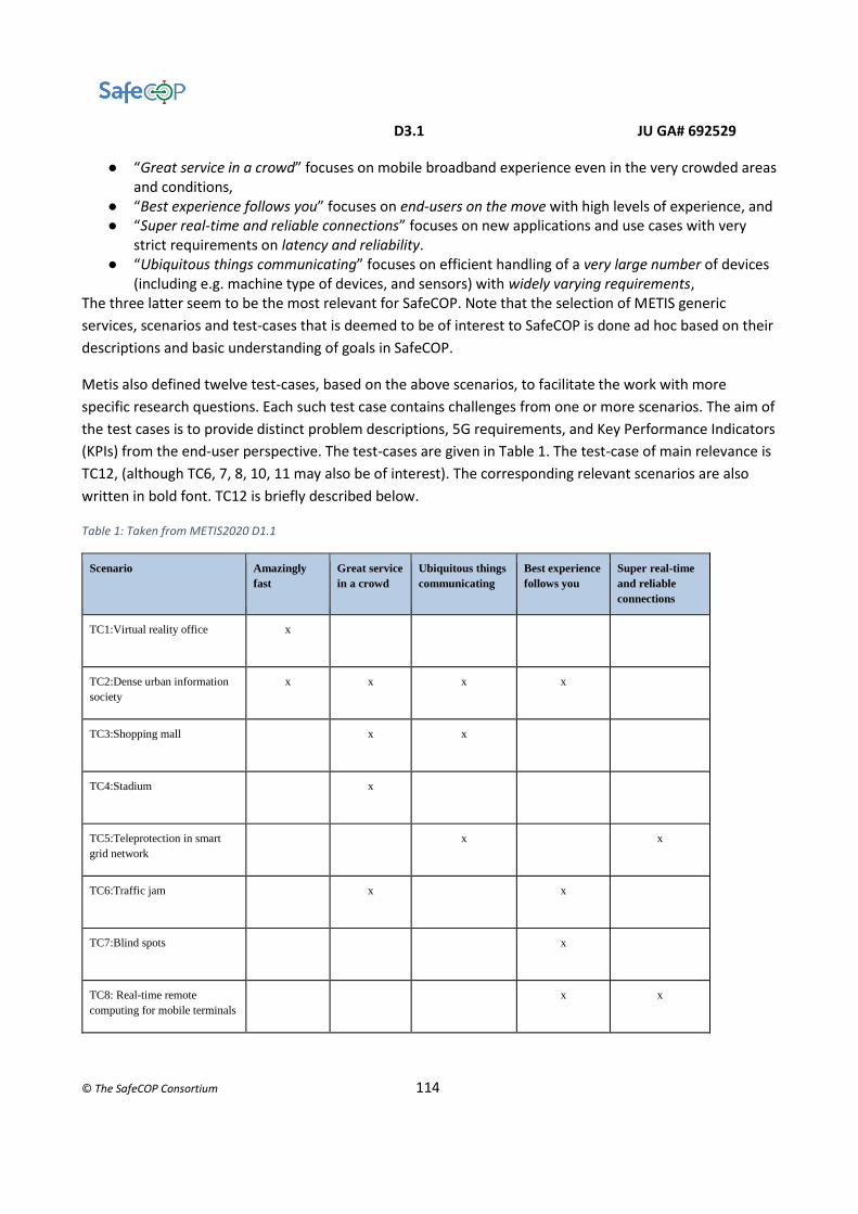
D3.1 JU GA# 692529
© The SafeCOP Consortium 114
● “Great service in a crowd” focuses on mobile broadband experience even in the very crowded areas and conditions,
● “Best experience follows you” focuses on end-users on the move with high levels of experience, and ● “Super real-time and reliable connections” focuses on new applications and use cases with very
strict requirements on latency and reliability. ● “Ubiquitous things communicating” focuses on efficient handling of a very large number of devices
(including e.g. machine type of devices, and sensors) with widely varying requirements, The three latter seem to be the most relevant for SafeCOP. Note that the selection of METIS generic
services, scenarios and test-cases that is deemed to be of interest to SafeCOP is done ad hoc based on their
descriptions and basic understanding of goals in SafeCOP.
Metis also defined twelve test-cases, based on the above scenarios, to facilitate the work with more
specific research questions. Each such test case contains challenges from one or more scenarios. The aim of
the test cases is to provide distinct problem descriptions, 5G requirements, and Key Performance Indicators
(KPIs) from the end-user perspective. The test-cases are given in Table 1. The test-case of main relevance is
TC12, (although TC6, 7, 8, 10, 11 may also be of interest). The corresponding relevant scenarios are also
written in bold font. TC12 is briefly described below.
Table 1: Taken from METIS2020 D1.1
Scenario Amazingly
fast Great service
in a crowd Ubiquitous things
communicating Best experience
follows you Super real-time
and reliable
connections
TC1:Virtual reality office x
TC2:Dense urban information
society x x x x
TC3:Shopping mall x x
TC4:Stadium x
TC5:Teleprotection in smart
grid network x x
TC6:Traffic jam x x
TC7:Blind spots x
TC8: Real-time remote
computing for mobile terminals x x
D3.1 JU GA# 692529
© The SafeCOP Consortium 115
TC9:Open air festival x x
TC10:Emergency
communications x x x
TC11:Massive deployment of
sensors and actuators x x x
TC12:Traffic efficiency and
safety x x
TC12 is centred on Cooperative intelligent traffic systems (C-ITS) and address the challenges of traffic
accidents, improving travel time, fuel consumption and pollution. The communication requirements of
cooperative driving applications, such as platooning (road-trains) and highly automated driving is
addressed. Cooperation between vehicles or between vehicles and infrastructure is required, but also the
cooperation between vehicles and vulnerable road users, e.g. pedestrians and cyclists, through their mobile
devices, such as smartphone and tablets. C-ITS systems rely on timely and reliable exchange of information.
Common to most applications are real-time requirements, and strict requirements on reliability and
availability, especially when considering high mobility and large message sizes. End-to-end latency
requirements of less than 5 ms for message sizes of about 1600 byte need to be guaranteed for 99,999% of
V2X transmissions. Data is sent either event-driven or periodically with a rate of about 10 Hz. Relative
speed of up to 500 km/h are assumed. The detection range is assumed to be up to 1km.
Channel model
A stochastic channel model for vehicle-to-vehicle (V2V) is presented in [KTC+09]. The model is based on
extensive measurements in highway and rural environments at 5.2 GHz which is close enough to the 5.9
GHz band dedicated to V2V communication.
5G and 802.11p
Global development of 5G is outlined in the report [5G development], and also gives some comments on
the relation to IEEE 801.11p. Relevant quotes (see page 9) concerning the coexistence of 5G and ITS-G5
from the report are given below:
“In the case of connected vehicles, it is not envisaged that 5G would simply supersede earlier investments in
ITS-G517 technology, as currently deployed in Europe and in other regions of the world.”
“The main scenario contemplated for the introduction of 5G functionalities is for the provision of additional
services compared to the earlier rolled out technologies, following a hybrid communication approach.”
The last quote concerns “day 1” ITS-service, such as “Road works warning” or “In-vehicle signage”, that are currently being rolled out; using 802.11p.

D3.1 JU GA# 692529
© The SafeCOP Consortium 116
802.11p
IEEE 802.11p standard is known as Wireless Access in Vehicular Environments (WAVE) in the overview of
protocols for DSRC-based operations. Released in 2010, it is especially developed to adapt IEEE 802.11 to
VANETs requirements and support intelligent transport systems (ITS). It defines physical and medium access
control layers of VANETs, while IEEE 1609 protocol family which developed higher layer specification based
on 802.11p.
This protocol consists of four documents:
● IEEE 1609.1: describes resource manager specification
● IEEE 1609.2: defines the formats and processing of secure messages
● IEEE 1609.3: covers network and transport layer services
IEEE 1609.4: specifies improvement to the IEEE 802.11p MAC to support multichannel operation
4.1.1.1 Physical Layer
The main features are [1], [2]:
● 5.9GHz band (5.850 - 5.925) GHz;
● Data Rate: 3 up to 27 Mbps (depending of the modulation schemes, like BPSK, QPSK, 16-QAM, 24-
QAM);
● 7 licensed channels;
● Range: up to 1000m;
● These features makes IEEE 802.11p fit for the purpose of V2I and V2V application fields.

D3.1 JU GA# 692529
© The SafeCOP Consortium 117
Two sub-layers:
PLCP The first one is the Physical Layer Convergence Protocol (PLCP) which is
· responsible for communicating with the MAC layer.
· convergence process that transforms the Packet Data Unit (PDU) arriving from the MAC layer to
compose an OFDM frame (RX).
PDM Physical Medium Access The second sub-layer is the Physical Medium Access (PMD) which is
the interface to the physical transmission medium such as radio channels and fibre links. Its task is
to manage data encoding and perform the modulation
The management functions connected to the physical layer are called Physical Layer Management Entity
(PLME).
Mechanism: OFDM Orthogonal Frequency Division Multiplex.
Because of the peculiar Low SNR Signal To Noise Ratio of IEEE 802.11p, the adoption of OFDM is suitable to
overcome the effect of wireless channel on the signal properties. It may alter the phase and frequency of the
signal by some values, which may affect the demodulation process. These effects often are phase rotation,
Doppler frequency shift, degradation of the amplitude and phase distortion.
All of these effects cause poor SNR. One of the considerable effects is it may alter the place of the frequency
of some subcarriers in an OFDM, which may cause the loss of signals orthogonality characteristic.
Pilot symbols are used for the purpose of channel estimation and transmission error correction.
At the transmitter a well-known symbol (its frequency, amplitude and phase) is inserted among the
subcarriers to carry the effects of the channel.
At the receiver it demodulated and then all the effects are calculated and the received signal is corrected and
estimated according to those calculated amounts.
The number of pilots used in an OFDM system depends on the characteristics of the channel through which
the signal is sent. It employs IFFT and FFT to translate the transmitted message into the frequency domain
and it estimates the frequency response of the channel and equalizes the channel in the frequency domain.
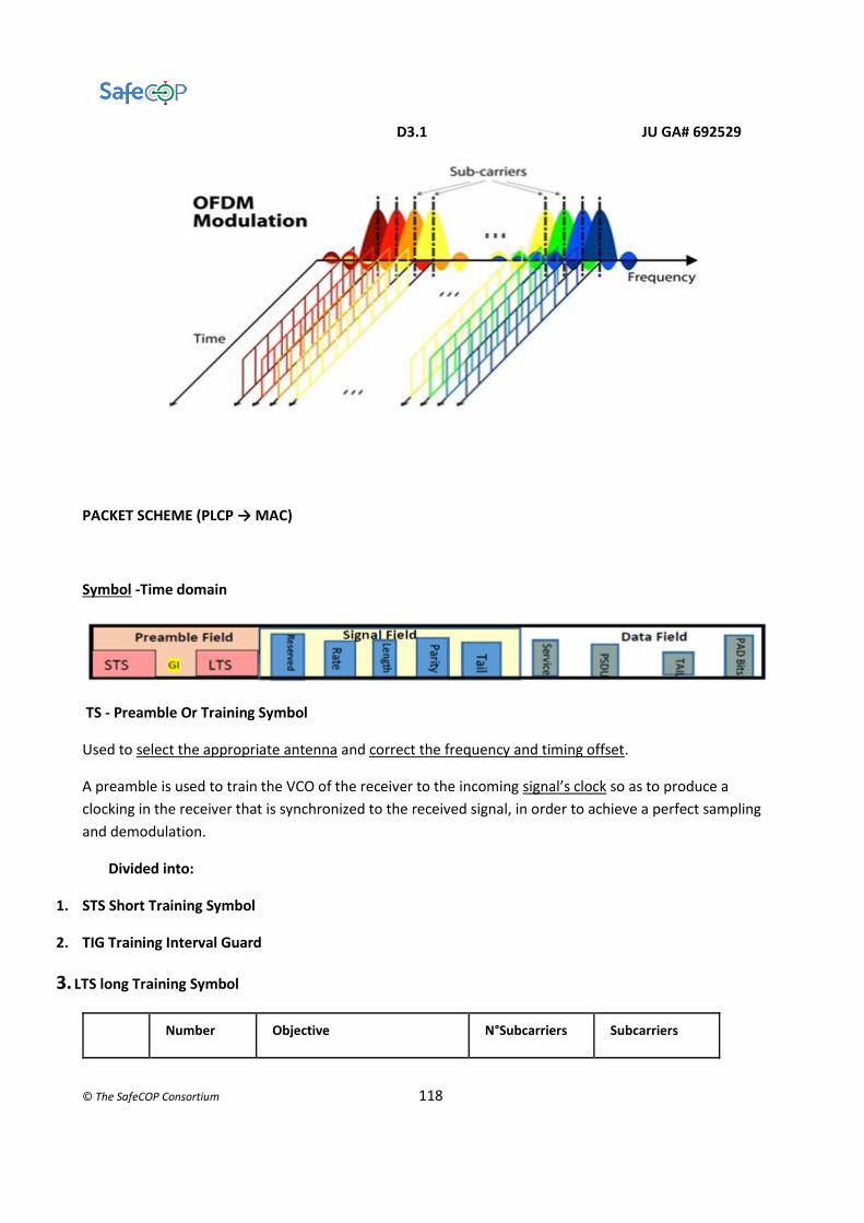
D3.1 JU GA# 692529
© The SafeCOP Consortium 118
PACKET SCHEME (PLCP → MAC)
Symbol -Time domain
TS - Preamble Or Training Symbol
Used to select the appropriate antenna and correct the frequency and timing offset.
A preamble is used to train the VCO of the receiver to the incoming signal’s clock so as to produce a
clocking in the receiver that is synchronized to the received signal, in order to achieve a perfect sampling
and demodulation.
Divided into:
1. STS Short Training Symbol
2. TIG Training Interval Guard
3. LTS long Training Symbol
Number Objective N°Subcarriers Subcarriers

D3.1 JU GA# 692529
© The SafeCOP Consortium 119
STS 10 7 responsible of the signal
detection, automatic gain
control (AGC) and diversity
selection
12 ± (4, 8, 12, 16,
20, and 24)
3 coarse frequency offset and
timing synchronization,
estimation of subcarriers
frequency and channel
estimation
TIG 1 avoid interference between STS
and LTS
LTS 2 channel estimation and fine
frequency acquisition in the
receiver
52+
1(The receiver
uses it for fine-
tuning)
TS Total Duration= T STS + T TIG + T LTS, 32 μs = (10*1, 6) + 3.2 + (2*6.4)
SIG - Signal Field
This field specifies the rate and length information.
BPSK modulated at 6 Mbps and is encoded at a ½ rate
interleaved and mapped
It has pilots inserted in subcarriers –21, –7, 7 and 21.
Not scrambled
divided into five sub fields: the RATE, RESERVED, LENGTH, PARITY and TAIL.
The RATE field is the first 4 bit which conveys information about the type of modulation and the coding
rate used in the rest of the packet. The encoding procedure includes:
*convolutional encoding,
*interleaving,
*modulation mapping processes
*pilot insertion,
*while OFDM modulation used for the transmission of data at a specific rate.
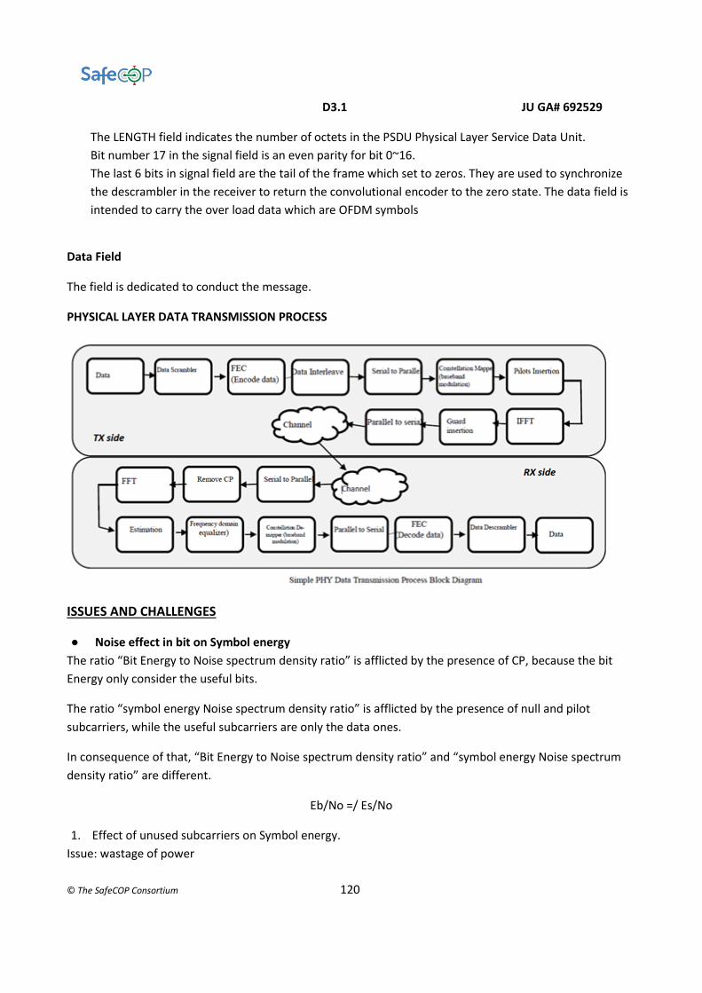
D3.1 JU GA# 692529
© The SafeCOP Consortium 120
The LENGTH field indicates the number of octets in the PSDU Physical Layer Service Data Unit.
Bit number 17 in the signal field is an even parity for bit 0~16.
The last 6 bits in signal field are the tail of the frame which set to zeros. They are used to synchronize
the descrambler in the receiver to return the convolutional encoder to the zero state. The data field is
intended to carry the over load data which are OFDM symbols
Data Field
The field is dedicated to conduct the message.
PHYSICAL LAYER DATA TRANSMISSION PROCESS
ISSUES AND CHALLENGES
● Noise effect in bit on Symbol energy
The ratio “Bit Energy to Noise spectrum density ratio” is afflicted by the presence of CP, because the bit
Energy only consider the useful bits.
The ratio “symbol energy Noise spectrum density ratio” is afflicted by the presence of null and pilot
subcarriers, while the useful subcarriers are only the data ones.
In consequence of that, “Bit Energy to Noise spectrum density ratio” and “symbol energy Noise spectrum
density ratio” are different.
Eb/No =/ Es/No
1. Effect of unused subcarriers on Symbol energy.
Issue: wastage of power
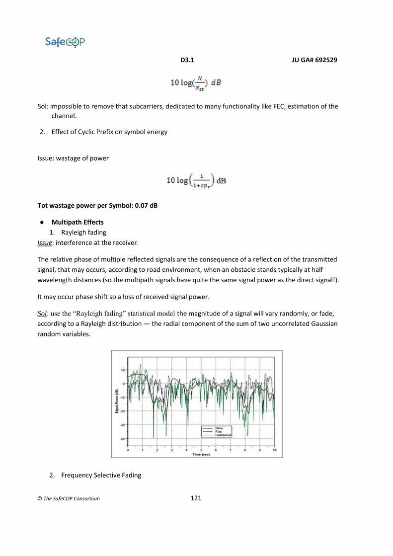
D3.1 JU GA# 692529
© The SafeCOP Consortium 121
Sol: impossible to remove that subcarriers, dedicated to many functionality like FEC, estimation of the
channel.
2. Effect of Cyclic Prefix on symbol energy
Issue: wastage of power
Tot wastage power per Symbol: 0.07 dB
● Multipath Effects
1. Rayleigh fading
Issue: interference at the receiver.
The relative phase of multiple reflected signals are the consequence of a reflection of the transmitted
signal, that may occurs, according to road environment, when an obstacle stands typically at half
wavelength distances (so the multipath signals have quite the same signal power as the direct signal!).
It may occur phase shift so a loss of received signal power.
Sol: use the “Rayleigh fading” statistical model the magnitude of a signal will vary randomly, or fade,
according to a Rayleigh distribution — the radial component of the sum of two uncorrelated Gaussian
random variables.
2. Frequency Selective Fading

D3.1 JU GA# 692529
© The SafeCOP Consortium 122
Selective fading or frequency selective fading is a radio propagation anomaly caused by partial
cancellation of a radio signal by itself as saying that cancellation of certain frequencies at the
receiver— the signal arrives at the receiver by two different paths, and at least one of the paths is
changing (lengthening or shortening). This typically happens in the early evening or early morning
as the various layers in the ionosphere move, separate, and combine.
Issue: Channel effect is cancellation of certain frequency (random phenomena) at the receiver, it
causes Destructive interferences result in “deep nulls”.
In a narrow bandwidth transmission, like in WAVE, if the null frequency coincide with the
transmission frequency, the entire signal is lost!
Sol: OFDM transmission, so the entire signal is divided into many subcarriers , namely the signal is
spread over a wide bandwidth. In that case, the null are likely to affect a small number of
subcarriers.
In any case, the lost carriers could be recovered by using FED techniques.
Drawback: complexity in receiver and transmitter design.
3. Delay Spread
Issue: spread the received energy. The compresence of direct and reflected signals implies multiple
paths and different arrival times at the receiver.
Delay Spread: Delta time is defined as the difference between the last significant multipath signal
time arrival and first multipath signal time arrival.
If delay Spread is higher than 50% of the bit time or Symbol period, than the amount of ISI
increases. This fading occurs when the channel introduces time dispersion and the delay spread is
larger than the symbol period. Frequency-selective fading is difficult to compensate because the
fading characteristics are random and may not be easily predictable.
When there is no dispersion and the delay spread is less than the symbol period, the fading will be
flat, thereby affecting all frequencies in the signal equally. Practically flat fading is easily estimated
and compensated with a simple equalization.
Sol -in WAVE: technique that introduces GI Guard Interval between one symbol and another.
(Alternative sol: CDMA (Code Division Multiple Access) coding scheme, that is tolerant to ISI.
This coding scheme is used in 802.11b [3])
Challenge: find a method/mechanism to contrast the reduction of bit rate, caused by the GI
adoption
● Doppler Shift
Issue: the deviation of the source vehicle frequency at the receiver. (+-7,708 kHz)
Cause: OFDM transmission technique is sensitive to carrier frequency offset.

D3.1 JU GA# 692529
© The SafeCOP Consortium 123
Challenge: mechanism that able to train transmitter or receivers to adjust their frequency
according to given Doppler equations parameters.
● Channel variation and channel estimation
Training Symbol contains the request CSI (Channel State Information).
Issue: The response in reception is variable due to the channel state variation (fast fading and
mobility effects).
Challenge: find an appropriate estimation system that adapt vehicular network and achieve low
BER, high reliability and simple receiver design.
● Network Coverage Range
Issue: More communication distance between vehicles.
In VANETs the use of multi-hop may not be applicable, consequently, a more communication
distance between vehicles is needed.
The maximum coverage area of vehicular network according to WAVE standards is about 1Km,
however 7db is needed for 150m using IEEE802.11p technology.
This means, to increase the coverage, more power is needed.
Challenge: How to increase the coverage area within the maximum allowable power?
● Bit rate enhancement techniques
Issue: High data rate for content (video, audio, images like maps, internet data)
Limitations of PHY layer regard some of vehicular network characteristic exactly mobility: the bit
rate is 27 Mbps (half compared to the 802.111 one).
Objective with the condition of maximizing the utilization of the bandwidth: increase the bit rate,
reduce BER.
Sol: get an improvement in communication techniques (modulation, FEC size, frame size)
4.1.1.2 MAC Layer
The management functions connected to the MAC layer is called MAC Layer Management Entity
(MLME).

D3.1 JU GA# 692529
© The SafeCOP Consortium 124
The fundamental access method of the IEEE 802.11 MAC is a DCF known as Carrier Sense Multiple Access
with Collision Avoidance (CSMA/CA). It is based on the 802.11e EDCA, Enhanced Distributed Channel Access
that is an enhanced version of Distributed coordination function DCF from 802.11. [4]
EDCA mechanism defines four different access categories (AC) for each channel, and each of them has an
independent queue.
The EDCA mechanism provides prioritization by assigning different contention parameters to each access
category. AC3 has the highest priority to access medium, whereas AC0 has the lowest priority.
Each frame is categorized into different access categories, depending on the importance of the message.
Two contention procedures: That internal prioritization leads to an internal contention procedure which
occurs inside each channel between their access categories by using the contention parameters (AIFS,
Arbitration Interframe Space, and CW, Content Window).
After that it happens another contention:
The contention procedure between channels to access the medium supported by different timer settings
based on the internal contention procedure.
The adopted decentralized real-time system is CSMA/CA CARRIER SENSE MULTIPLE ACCESS/COLLISION
AVOIDANCE
Based on the ALOHAnet protocol (1970), this algorithm works as follows: for every sending frame attempt
failed (collision) the binary exponential back off procedure associates a value (a multiple of the slot time, a
parameter of PHY). The retransmission timeout is proportional to an exponential of c, number of collision:

D3.1 JU GA# 692529
© The SafeCOP Consortium 125
after each consequent attempt, the probability of delay increases exponentially, up to a ceiling value (then
the retransmission is aborted).
According to the algorithm, a node sends a RTS frame, request to send, to an AP Access Point to gain the
access instead of other devices. If the channel is idle, the AP sends a CTS frame, clear to send, to this node
and an advertisement frame to other nodes that the channel is busy. This procedure contrasts the hidden
node problem and the exposed node problem.
Due to the decentralized nature of the networks, the communication is broadcast so the back off procedure
run one time and the back off decrement takes place one time (MAC 802.11p protocol is a Stop-and-wait
protocol) and that leads to the problem: only one back off decrement will take place for an eventually
retransmission and the node sender never knows if anyone has received the packet correctly.
In the beacon-enabled network, the adopted version is the slotted version of CSMA-CA.
For the safety application of VANETs, the STDMA has not been implemented in the protocol because it
requires position information to function, meaning that it needs an external party that may suffer from
failure or from loss of coverage; and slot synchronization, that makes it more complex. A drawback is a
potential increase in interference due to the reused slots. Otherwise STDMA has the reducing of packet
drops as an advantage [6]
ISSUES AND CHALLENGES
Real time communication constraints
Issue: Fairness in Channel Access in V2I communications
Sol: Speed Factor on MAC Layer
As shown in the simulation executed in [7]:
Give each node in the network a priority based on the vehicle speed.
According to the gained results we can group nodes into high and low speed and give priority respectively
if the amount of D (deviation from the medium speed in the range of RSU) is high or low, so one node can
have a maximum and a minimum back off contention window size (CWmin and Cwmax). Simulation
outcome is the reduction of retransmission, vehicle collision and packets lost. (The ratio of packet
delivering and fairness has been efficiently gained).
IEEE 802.15.4 The IEEE 802.15 Working Group for Wireless Personal Area Networks has developed a protocol suitable to
the requirements of Low data rate, low power WPAN (LP-WPAN), characterised by a battery life ranging from
months to several years and very low complexity.

D3.1 JU GA# 692529
© The SafeCOP Consortium 126
PHYSICAL LAYER
Intending to operate in unlicensed and international frequency bands, the spectrum allocation is:
● 1 channel at 868 MHz EUROPE, direct sequence spread-spectrum (DSSS),
● 10 channels in the 915 MHz band,
● 16 channels in the 2.4 GHz band.
PHY operation required:
● switching on/off the transceiver;
● defining the receiver sensitivity;
● defining band;
● defining the modulation and spreading;
● ED, Energy Detection, measure the energy received;
● LQD, Link Quality Detection, evaluate a LQI, the indicator representing the link quality, an
evaluation of the packet (collect also the info from ED);
● CCA, Clear Channel Assessment, to provide the upper layer an assessment of the state of the
channel, occupied or not, while receiving a packet; this information is crucial to select the
better channel, transmit and receive. This algorithm has three modes :
○ Energy above threshold;
○ Carrier sense only;
○ Carrier sense with energy above threshold.
Modulation: either MSK or BPSK (depending on the data rate) [EUROPE: BPSK], this standard transmits a
spread spectrum signal;
Access Method: slotted CSMA/CA (suitable for typical infrequent transmission of typical short packets for a
very low duty cycle);

D3.1 JU GA# 692529
© The SafeCOP Consortium 127
Power transceiver: max -3 dB or 0.5 mW (to 20 dB of some available modules);
Receiver sensitivity: -92dBm;
Coverage Area:
● 10-75 m nominally indoor or NLOS (not in line of sight);
● 1000 m outdoor or LOS;
Nominally coverage area is 10 meters, but higher output power and better receiver sensitivity (a larger link
budget) will extend effective range. However, higher transmit power levels will also adversely affect battery
life. Fortunately, most 802.15.4-compliant devices offer a range of register-selectable transmit power levels,
up to about +4 dBm, which provides the flexibility to adjust according to the application.
MAC LAYER
The MAC layer provides an interface between the application layer and the PHY layer; it included in this
standard supports various ad-hoc topologies and guaranteed packet delivery.
The MAC layer provides services to the application layer through two groups:
● MAC Layer Management Entity (MLME), provides the MAC Management Service. The MLME
provides the service interfaces through which layer management functions may be invoked.
The MLME is also responsible for maintaining a database of managed objects pertaining to
the MAC layer. This database is referred to as the MAC layer PAN information base (PIB). The
MLME also has access to MCPS services for data transport.
● MAC Common Part Layer (MCPS), provides the MAC Data Service. The MCPS provides data
transport services between peer MACs.
Hardware support: IRIS, MicaZ, TelosB
The IEEE 802.15.4-2006 protocol supports the following two operational modes:
1. Non beacon-enabled mode: When the coordinator selects the non-beacon enabled mode, there are
neither beacons nor superframes. Medium access is ruled by an unslotted CSMA/CA mechanism.
2. Beacon-enabled mode: In this mode, beacons are periodically sent by the coordinator or router to
synchronize nodes that are associated with it, and to identify the PAN. A beacon frame delimits the
beginning of a superframe defining a time interval during which frames are exchanged between
different nodes in the PAN. Medium access is basically ruled by Slotted CSMA/CA. However, the
beacon-enabled mode also enables the allocation of contention free time slots, called Guaranteed
Time Slots (GTSs) for nodes requiring guaranteed bandwidth.
Superframe Structure
The superframe is defined between two beacon frames and has an active period and an inactive period. The
following figure depicts the IEEE 802.15.4 superframe structure. The active portion of the superframe
structure is composed of three parts, the Beacon, the Contention Access Period (CAP) and the Contention
Free Period (CFP).

D3.1 JU GA# 692529
© The SafeCOP Consortium 128
Beacon: the beacon frame is transmitted at the start of slot 0. It contains the information on the addressing
fields, the superframe specification, the GTS fields, the pending address fields and other PAN related
information.
Contention Access Period (CAP): the CAP starts immediately after the beacon frame and ends before the
beginning of the CFP, if it exists. Otherwise, the CAP ends at the end of the active part of the superframe. The
minimum length of the CAP is fixed at aMinCAPLength = 440 symbols. This minimum length ensures that
MAC commands can still be transmitted when GTSs are being used. A temporary violation of this minimum
may be allowed if additional space is needed to temporarily accommodate an increase in the beacon frame
length, needed to perform GTS management. All transmissions during the CAP are made using the Slotted
CSMA/CA mechanism. However, the acknowledgement frames and any data that immediately
followstheacknowledgementofadatarequestcommandaretransmittedwithoutcontention. If a transmission
cannot be completed before the end of the CAP, it must be deferred until the next superframe.
Contention Free Period (CFP): The CFP starts immediately after the end of the CAP and must complete before
the start of the next beacon frame (if BO equals SO) or the end of the superframe. Transmissions are
contention-free since they use reserved time slots (GTS) that must be previously allocated by the coordinator
or router of each cluster. All the GTSs that may be allocated by the Coordinator are located in the CFP and
must occupy contiguous slots. The CFP may therefore grow or shrink depending on the total length of all
GTSs.
In beacon-enabled mode, each Coordinator defines a superframe structure in aforementioned figure which
is constructed based on the Beacon Interval (BI), which defines the time between two consecutive beacon
frames and the Superframe Duration (SD), which defines the active portion in the BI, and is divided into 16
equally-sized time slots, during which frame transmissions are allowed. BI and SD are determined by two
parameters, the Beacon Order (BO) and the Superframe Order (SO), respectively, as follows:
D3.1 JU GA# 692529
© The SafeCOP Consortium 129
An aBaseSuperframeDuration = 15.36 ms (assuming 250 kbps in the 2.4 GHz frequency band) denotes the
minimum duration of the superframe, corresponding to SO=0. As depicted in Figure 8, low duty cycles can
be configured by setting small values of the SO as compared to BO, resulting in greater sleep (inactive)
periods.
Guaranteed Time Slot (GTS) mechanism
The GTS mechanism allows devices to access the medium without contention, in the CFP. GTSs are allocated
by the Coordinator and are used only for communications between the Coordinator and a device. Each GTS
may contain one or more time slots. The Coordinator may allocate up to seven GTSs in the same superframe,
provided that there is sufficient capacity in the superframe. Each GTS has only one direction: from the device
to the Coordinator (transmit) or from the Coordinator to the device (receive).
The GTS can be deallocated at any time at the discretion of the Coordinator or the device that originally
requested the GTS allocation. A device to which a GTS has been allocated can also transmit during the CAP.
The Coordinator is responsible for performing the GTS management; for each GTS, it stores the starting slot,
length, direction, and associated device address. All these parameters are embedded in the GTS request
command. Only one transmit and/or one receive GTS are allowed for each device. Upon the reception of the
deallocation request the Coordinator updates the GTS.
TOPOLOGY
The protocol allows different topologies: star, cluster tree or mesh, where the participants belong to two
type of node: RDF, Reduced Function Device, and FFD, Full Function Device. The RFDs can only communicate
to or through the FFDs or through an FFD reaching an RFD; so the RFD is the end-device of star topologies,
they are typically battery-powered and low-memory devices; while FFDs are can communicate to both types
of node, so an FFD can act as end-device or router in every topology admitted.
An FFD work as coordinator: initialization the network, managing the nodes and store the topology's
information.

D3.1 JU GA# 692529
© The SafeCOP Consortium 130
ZigBee
PHYSICAL LAYER and MAC LAYER
Allocation spectrum is on unlicensed frequencies that are UHF (868 MHz in Europe) and 915 MHz in America
and ISM (2.4 GHz) worldwide.
The lower layers are IEEE 802.15.4 compliant. All the details are discussed in § IEEE 802.15.4, nevertheless
the main characteristics in effect in Europe are summarized as follows [2]:
● Frequency : 868 MHz – 868,6;
● Channel: 1;
● Bandwidth: 600 kHz;
● Data Rate : 20 kbit/s;
● Modulation: BPSK;
● Access method: slotted CSMA/CA;
● Coverage Range : 10-75 meters indoor, up to 1000 meters outdoor or in LOS (Line-Of-sight) thanks
to multi-hop;
● Latency: 30 ms.
NETWORK LAYER (NWK)
The protocol adopts a multihop routing and imposes an idle interval time to the node in line with the energy
consumption constraint, so the parents have to keep track of messages for sleeping children.

D3.1 JU GA# 692529
© The SafeCOP Consortium 131
The mesh topology provides a redundancy of path, therefore a highly reliable and self-healing network.
The Network Layer provides an interface between the MAC Layer and the Application Layer [6], two entities
are dedicated to provide services:
● Network Layer Data Entity (NLDE). It generates the NPDU, Network Packet Data Unit, and manages
the Data and Command Frame routing and also the transmission security;
● Network Layer Management Entity (NLME). The provided services are: configuration of a new
device, constitution of a new network, association and disassociation, address assignment by the ZC,
individuation of the neighbour nodes, route discovery (best path), and receiver activity control.
APPLICATION LAYER
The structure of the Application Layer [6]:
● APS Application Support sub-layer;
● AF Application Framework;
● ZDO ZigBee Device Object.
The APS is the interface both between NWK layer and AF and between NWK and ZDO. It provides many
services to the tree of them. It stores the Binding tables (in the APS of the source node or of the Primary or
Backup Binding Table Cache Device, usually the router). The binding is the logical link (through end-points)
between the resident application of one device and one or more complementary applications of other
devices if and only if a previous association of both nodes to the network and the successfully match of the
security level have occurred.
The AF contains the application object (APP) and the user application, those ones communicate with the
layer below (APS) through the end-point or APSDE-SAP (APS Service Access Point). At each application object
is assigned one of the 240 end-point (on 256 available). The end-point 255 is the interface used in broadcast
communication to all the application objects. The ZDO is allocated on the end-point 0.
The ZDO it defines the role of the node in the network, accomplishes the discovery, manages the binding
request and establishes secure connection among nodes.
It also is in charge of initializing the APS, NWK and SSP.
The ZigBee application framework comprehends a variety of tailor-made solutions, from home automation
to industrial plant monitoring. Some fields: commercial building automation (Building control, management,
and monitoring), WSN Wireless Sensor Networks (very low power unattended networks).
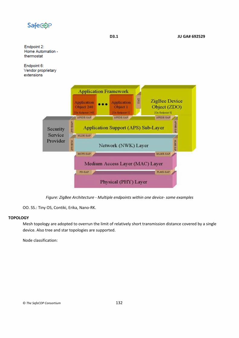
D3.1 JU GA# 692529
© The SafeCOP Consortium 132
Figure: ZigBee Architecture - Multiple endpoints within one device- some examples
OO. SS.: Tiny OS, Contiki, Erika, Nano-RK.
TOPOLOGY
Mesh topology are adopted to overrun the limit of relatively short transmission distance covered by a single
device. Also tree and star topologies are supported.
Node classification:

D3.1 JU GA# 692529
© The SafeCOP Consortium 133
● ZC ZigBee Coordinator, it is the network root (can create a new network and let other nodes join in),
support the NWK address assignment, it can start a route discovery and route repair activity and
optionally the store of network's security keys;
● ZR ZigBee Router, can associate/disassociate to/from a network and can allow other node joining
the network, store the neighbour node list, support the NWK address assignment, it can start a route
discovery and route repair activity, it can send beacon only in tree topology, support the mobility of
nodes;[6]
● ZED ZigBee End Device, basic functionality to communicate with the coordinator, (sending only their
data- no multi-hop and receiving from the parents nodes).Its periodic cycle is wake-poll-sleep. Sensor
node is typically a ZED.
The ZC and ZR have the same hardware, the only distinction is function-based: the ZC is in charge of initializing
the network.
The power consumption is the primary metric to design a sensor node. On an Embedded Sensor Board there
are a sensor detecting some parameters (like speed, acceleration, pollution in the event environment), a CPU
(8 MHz), a reduced capacity memory, a low-power transduct and a battery.
The limited computational load implies the possibility of design a low-cost CPU. [1]

D3.1 JU GA# 692529
© The SafeCOP Consortium 134
PERFORMANCES
The main metrics are throughput, data rate and average delay.
The experimental evaluation of ZigBee performances shows a lower data rate and throughput, and a higher
delay respect to the analytical results. [3]
Fig. Throughput - analytical and experimental result
The experimental trials is repeated 500 times for four different network configuration: some simplified
topology, from "1 coordinator - 1 RFD", passing through crescent number of intermediate routers
configuration, until reaching "1 coordinator-multiple router in line-1 RFD" configuration, furthermore a star
topology with two RFD.
THROUGHPUT
Due to the linear configuration, the channel is always free, so no collision happens. The throughput decrease
because a lower packet length and/or a higher number of hop (in multi-hop connection) occur.

D3.1 JU GA# 692529
© The SafeCOP Consortium 135
Fig. Throughput - two configuration compared
In the "1 coordinator-multiple router in line - 1 RFD" configuration, the experimental results highlight that
the throughput less than halves when the number of hop increase from one to two. It not haves because the
positive contribution of the minimizing path specific of ZigBee protocol (for example: the first router
communicates directly with the coordinator, skipping the second router).
The analytical solution is, instead, built on these relations with the main parameters: the linear increasing
trend between the throughput and the packet length and the inverse proportionality between the
throughput and the number of hops traversed by the packet in the route to the destination.
Moving to a more realistic non-linear configuration, the collision is a new parameter that slightly reduces the
throughput.
AVERAGE DELAY
The delay between two consecutive packets is a function of the packet length L, the transmission rate Rb and
the processing time at the node Tproc, while the propagation delay is reasonably unimportant.
𝐷 ≈ 𝐿/𝑅𝑏 + 𝑇𝑝𝑟𝑜𝑐
The average delay increase with the adding of an intermediate node, but this increasing trend is mitigated
by the growth of the packet length (the delay grows less with the increasing packet length).

D3.1 JU GA# 692529
© The SafeCOP Consortium 136
Figure: Average Delay - comparison between configurations
Packet Error Rate (PER)
Concerning the home application field, the metric tested for examining the performance proprietary
application is the PER, the ratio of the number of erroneous received packets to the total number of
transmitted packets.
When the distance between two consecutive nodes increases (beyond a certain threshold: 20m indoor, e.g.
home application), the connectivity fails and the Packet Error Rate rears up (rapidly increases).
ENERGY EFFICIENCY
Different contributions to the ZigBee protocol are proposed; they have different point-of-view of the issue
but a reduction energy consumption goal in common.
Energy-balancing Algorithm [5], applied to the ZigBee standard, is demonstrated to affect the performances
in reducing the deviation in energy, compared to the constant-cost algorithm.
The aim is balancing the nodes' energy and reducing the energy consumption, (first of all, avoiding the node's
behaviour like a power hog, when a node uses an excessive amount of energy, up to all of the available
power).
This added algorithm help to reach the best path in that perspective, so it has favourable impact on the
routing activity.
The link loss �� is estimated:

D3.1 JU GA# 692529
© The SafeCOP Consortium 137
��=�(�⋅ �(��,��,����)+�⋅ �(
���))
�� energy of the node itself
�� energy of the adjacent node
���� mean area energy
��� Link Quality Indicator
�, � factor desumed by experiments
P(.)
function, it ensures that the link loss remains
between 0 and some developer-defined constant
(7 in this case)
Another contribution is the ADaptive Access Parameters Tuning (ADAPT) [4], an algorithm that does not
require any modification to the ZigBee standard so easily integrated into a diverse set of ZigBee sensor
networks; it acts on tuning the ZigBee MAC protocol according to the required reliability level of the current
application stack.
This approach implies adding a vertical adaptation module to the logical architecture.
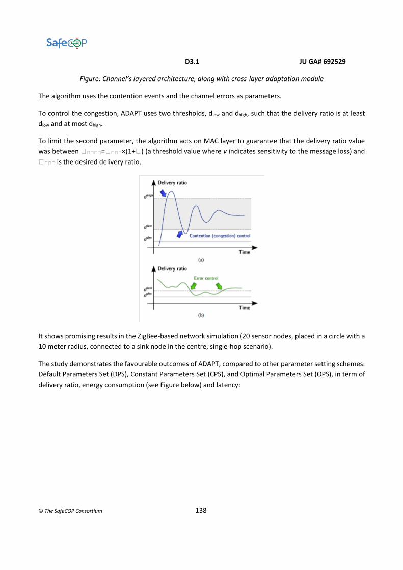
D3.1 JU GA# 692529
© The SafeCOP Consortium 138
Figure: Channel’s layered architecture, along with cross-layer adaptation module
The algorithm uses the contention events and the channel errors as parameters.
To control the congestion, ADAPT uses two thresholds, dlow and dhigh, such that the delivery ratio is at least
dlow and at most dhigh.
To limit the second parameter, the algorithm acts on MAC layer to guarantee that the delivery ratio value
was between �����=����×(1+�) (a threshold value where v indicates sensitivity to the message loss) and
���� is the desired delivery ratio.
It shows promising results in the ZigBee-based network simulation (20 sensor nodes, placed in a circle with a
10 meter radius, connected to a sink node in the centre, single-hop scenario).
The study demonstrates the favourable outcomes of ADAPT, compared to other parameter setting schemes:
Default Parameters Set (DPS), Constant Parameters Set (CPS), and Optimal Parameters Set (OPS), in term of
delivery ratio, energy consumption (see Figure below) and latency:

D3.1 JU GA# 692529
© The SafeCOP Consortium 139
Figure: Energy consumption
SCALABILITY
The presence of an FFD as PAN coordinator and other FFD acting as sub-net coordinator allows the auto-
configuration of a new node. The node's association occurs after the node has receipt a beacon from the
router or coordinator of the network the node want to join.
The maximum number of nodes supported is 65536.
The ZigBee interesting features is the efficient energy consumption adopting a low duty cycle (in sleep
mode, the node consumes less than 1 mA, while 35 mA in TX [2]); this makes ZigBee suitable for energy
supply limited network, like WSNs. [1]
Figure: Data Rate VS Energy Consumption
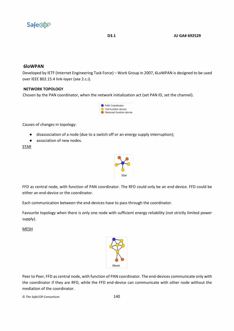
D3.1 JU GA# 692529
© The SafeCOP Consortium 140
6loWPAN
Developed by IETF (Internet Engineering Task Force) – Work Group in 2007, 6LoWPAN is designed to be used
over IEEE 802.15.4 link-layer (see 2.c.i).
NETWORK TOPOLOGY
Chosen by the PAN coordinator, when the network initialization act (set PAN ID, set the channel).
Causes of changes in topology:
● disassociation of a node (due to a switch off or an energy supply interruption);
● association of new nodes.
STAR
FFD as central node, with function of PAN coordinator. The RFD could only be an end-device. FFD could be
either an end-device or the coordinator.
Each communication between the end-devices have to pass through the coordinator.
Favourite topology when there is only one node with sufficient energy reliability (not strictly limited power
supply).
MESH
Peer to Peer, FFD as central node, with function of PAN coordinator. The end-devices communicate only with
the coordinator if they are RFD, while the FFD end-device can communicate with other node without the
mediation of the coordinator.
D3.1 JU GA# 692529
© The SafeCOP Consortium 141
The difference with Star: the path redundancy. The structure is more complex respect to the star topology
structure, the same note could be done on the requested routing algorithm:
SOFTWARE
The software suitable to the LLNs have to satisfy different requirements.
Limited energy supply for hardware imposes the minimizing energy consumption, so the SW has to show an
efficient management of resources and devices.
Due to limited sensor's memory (max 128 Kbyte), it is necessary to minimize the SW size.
The LLNs find application in different fields, so the SW implementation has to take count of different
hardware of the devices. The consequent requirement is a modular architecture to reduce the potential
future modifications, in case of re-implementation, that is adapting the SW to a new hardware.
The dynamic nature of LLNs' topology require a high SW reliability.
TinyOS is an example of Operating System successfully developed to manage the energy consumption of a
sensor node. It has been developed by WEBS group, University of Berkley, it is open source, and it is diffused
in both academic and industrial field.
NETWORK LAYER
The idea of the IETF WG is an Ipv6 protocol adapted to smallest devices' features.
Use of IP protocol to satisfy these requirements:
● the interoperability requirement and fit the size and interconnection features of the WSN.
● the robustness requirement of WSN implies a big amount of nodes (Ipv6 huge addresses space)
● auto-configuration mechanism as a requirement, to identify a new host without a router intervention
(see: Ipv6 link local unicast address).
What comes from IPv6:
IPv6 packet structure:

D3.1 JU GA# 692529
© The SafeCOP Consortium 142
● Basic Header 40 Bytes = 32 for address + 8 for additional field
32 Byte divided into: Source Address (128bit) and Destination Address (128bit)
8 Byte divided into:
4 bit – Version (identify this standard respect to the previous one)
4 bit – Priority (level of priority due to traffic congestion)
24 bit – Flow Label (experimental field)
16 bit – Payload Length (so the payload could be up to 65535 byte)
8 bit – Next header (indicates type of protocol for upper layer, ex: TCP, UDP, ICMPv6)
8 bit – Hop Limit (max number of hop before the discharge of the packet; this field is updated by each
intermediate node in the route to destination)
● Extension Header (optional field; present if request by the Basic Header.)
● Payload (up to 65535 byte)
● Address (Three types)
unicast: identify an interface (statement « an interface can belong only to one node » → one unicast address
can identify only one node → n° node's interfaces = n° unicast address can identify that node)
Classified by the validity:
● link-local , visibility and validity limited by the subnet (can't be used to reach other subnets);
● site-local;
● global.
any cast: identify a group of N interface, one address for each one of the N node (« one node to near »: the
packet send to an any cast address will be sent to the interface that answer the first or that is the nearest)

D3.1 JU GA# 692529
© The SafeCOP Consortium 143
multicast: identify a group of N interface, one for each one of the N node (« one to many », not to all! - the
packet send to a multicast address will be sent to all the interfaces allocated in that address)
In the WSN perspective, one of most relevant Ipv6 limit is that the broadcast communication is not
supported.
Address representation
An octet: each group required 16 bit and contains one to four digits or letters, the groups are separated by
colon.
The « :0000: » could be replaced by « :: » only once in an address. The simplification can be repeated many
times in the same addresser in case of « 0 » or « 0000 » at the beginning (e.g. 0:0:0:0:0:0:0:1 →::1).
Two visions of an address:
A) 128 bit as an all.
B) prefix + IID Interface Identifier.
Prefix obeys to the convention « ipv6_address/prefix_length » to describe which part of the address
belongs to that subnet and the number of bit used for describe the subnet. (subnet: a network
division at logical level, when a group of devices are configured with the same prefix: the logical
boundary is the route that connect this subnet to others).
IID identify the physical network the interface belongs to.
At least, the IID should be unique for the segment of network. It could be globally unique if it
complaints IEEE -EUI-64 standard, 64 bit = 24 bit company id +40 bit product serial number released
by the company.
Two length
Short, 16 bit or Extended, 64 bit (e.g. IEEE EUI-64 bit, EUI is Extended Unique Identifier)
Short: the coordinator of PAN assigns that, the validity is connected only to the validity of the association.
Extended: globally univocal, if IID complaints the IEEE EUI-64 bit.
Limits if Ipv6 and IP in general
Doesn't support broadcast transmission!
Designed for wired net, so it isn't suitable for respecting low data rate and low energy consumption
constraints.

D3.1 JU GA# 692529
© The SafeCOP Consortium 144
Packet Size Constraint. Ipv6 allows the single packet size to be up to 1280 byte that is incompatible with MTU
Maximum Transmission Unit IEEE 802.15.4 → 127 byte (changes between PHY protocols) when a packet has
to be encapsulated and sent to the lower layer.
Overhead reduce the acceptable IPv6 packet size from 127 to 102 (25 byte is the maximum frame overhead)
or even to 81 (optional overhead for security purpose), that is 80% or 63% of MTU.
In the worst case, the transmission efficiency « Ipv6 over IEEE 802.15.4 » is only 50% (The Ipv6 Header is 40
bytes, the packet size in IEEE 802.15.4 is 81 bytes, 63% MTU).
The problems is to overcome trying to reduce the IPv6 header size without losing the semantic value, so the
IETS WG decided to adopt a fragmentation mechanism (contained in the ADAPTATIVE LAYER between MAC
and NET ).
ASSOCIATION TO A PAN: configuration or auto-configuration
From IPv6, the configuration procedure concern these steps: the host sends router solicitation requests and
an IPv6 router responds with a prefix assignment. The host adds the IID to the prefix. In case the IID is short,
use a mechanism that leads to a pseudo-address (48 bit) and then to an address 64 bit (placing 32 bit of zeros
and a fix pattern).
6LoWPAN imposes the common prefix to the hosts of the same subnet. Adding this prefix to the IID build as
above, this protocol allows the broadcast among hosts with the same network prefix. This is the overrun of
the limit of Ipv6 that does not support broadcast communication, while this communication is native in
IEEE 802.15.4.
ADAPTATIVE LAYER
It is a layer between the MAC layer and NET layer.
Header Compression Mechanism
A header compression mechanism is indispensable to use the IPv6 on IEEE 802.15.4 network. It's defined HC-
1 , Header Compression 1, its aim is eliminating the redundant information that are contained in IPv6
addresses (IPv6 Basic Header) and are common for all host of the same 6LoWPAN network:
● version
● traffic classified

D3.1 JU GA# 692529
© The SafeCOP Consortium 145
● flow label
● payload length
Another contribution is adopting link-local address, where the IID is automatically configured, so the prefix
field in IPv6 Header can be eliminated, because the static prefix is in the MAC header, in particular in the
Address Information field.
The compressed IPv6 Basic Header is illustrated below:
At minimum, the IPv6 Header occupies 2 byte (from 40 byte without compression mechanism): one byte
for HD-1, one byte for Hop Limit Field.
The HC1 Encoding byte indicates if the information in the IPv6 header have been compressed, and, in that
case, it indicates which ones.
Setting the bit 0 and 2 equal to 1 means that the source IPv6 prefix and destination IPv6 prefix are
compressed, so it is necessary to extract the addresses from the Link-local. Otherwise the prefix should be
entirely inserted in the header.
UDP HC-1
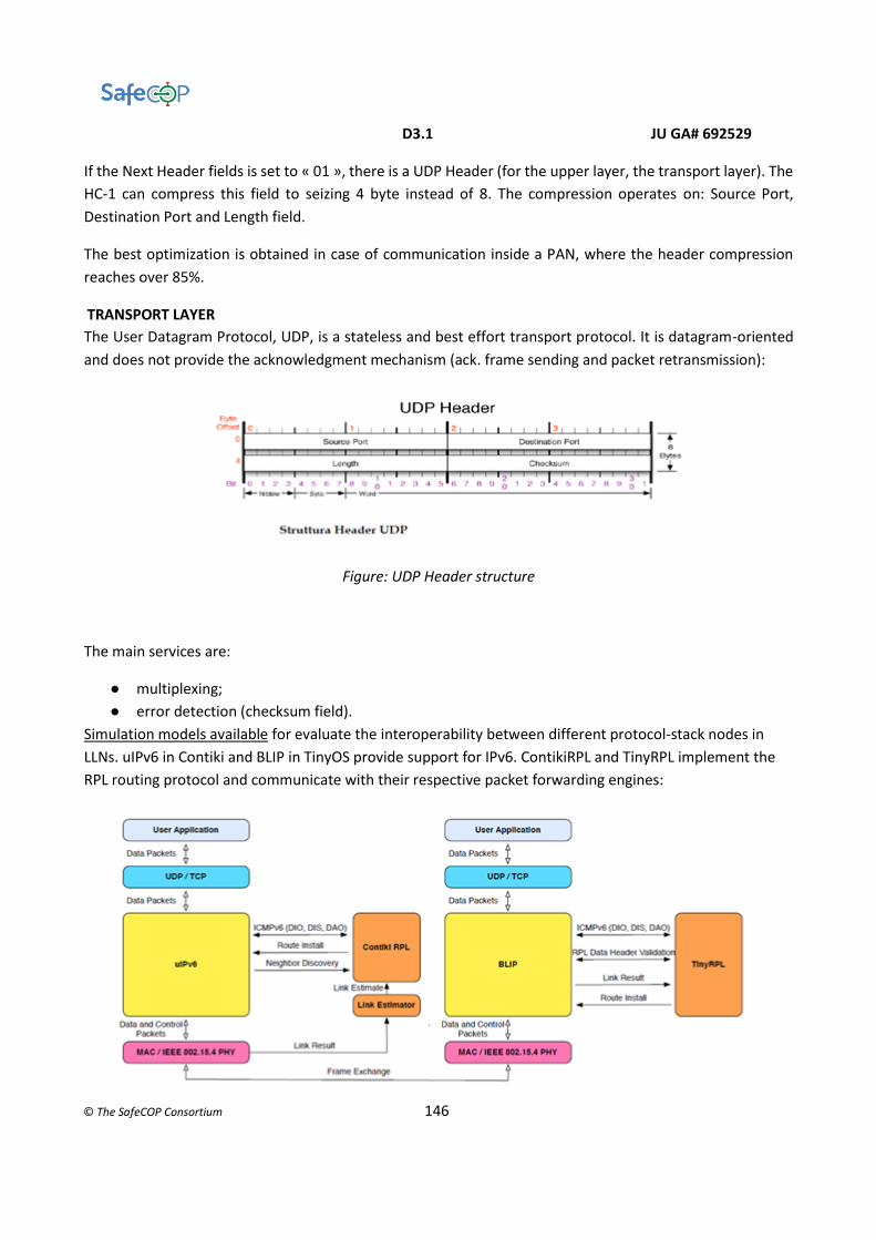
D3.1 JU GA# 692529
© The SafeCOP Consortium 146
If the Next Header fields is set to « 01 », there is a UDP Header (for the upper layer, the transport layer). The
HC-1 can compress this field to seizing 4 byte instead of 8. The compression operates on: Source Port,
Destination Port and Length field.
The best optimization is obtained in case of communication inside a PAN, where the header compression
reaches over 85%.
TRANSPORT LAYER
The User Datagram Protocol, UDP, is a stateless and best effort transport protocol. It is datagram-oriented
and does not provide the acknowledgment mechanism (ack. frame sending and packet retransmission):
Figure: UDP Header structure
The main services are:
● multiplexing;
● error detection (checksum field).
Simulation models available for evaluate the interoperability between different protocol-stack nodes in
LLNs. uIPv6 in Contiki and BLIP in TinyOS provide support for IPv6. ContikiRPL and TinyRPL implement the
RPL routing protocol and communicate with their respective packet forwarding engines:
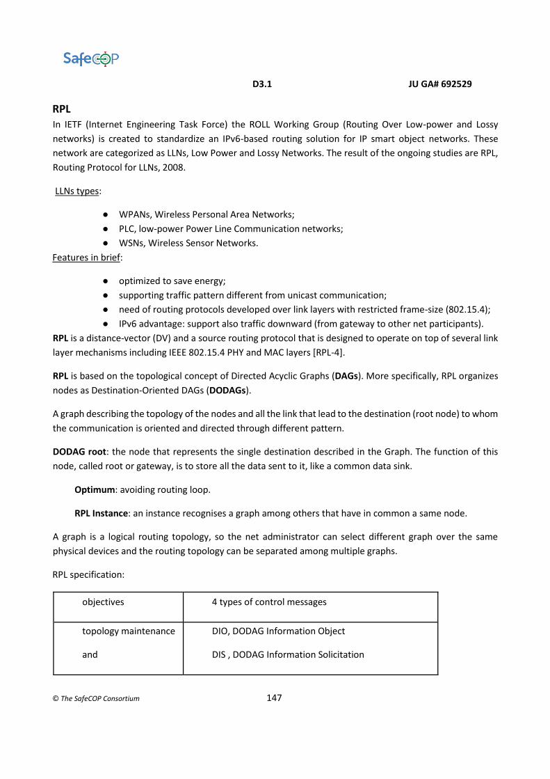
D3.1 JU GA# 692529
© The SafeCOP Consortium 147
RPL
In IETF (Internet Engineering Task Force) the ROLL Working Group (Routing Over Low-power and Lossy
networks) is created to standardize an IPv6-based routing solution for IP smart object networks. These
network are categorized as LLNs, Low Power and Lossy Networks. The result of the ongoing studies are RPL,
Routing Protocol for LLNs, 2008.
LLNs types:
● WPANs, Wireless Personal Area Networks;
● PLC, low-power Power Line Communication networks;
● WSNs, Wireless Sensor Networks.
Features in brief:
● optimized to save energy;
● supporting traffic pattern different from unicast communication;
● need of routing protocols developed over link layers with restricted frame-size (802.15.4);
● IPv6 advantage: support also traffic downward (from gateway to other net participants).
RPL is a distance-vector (DV) and a source routing protocol that is designed to operate on top of several link
layer mechanisms including IEEE 802.15.4 PHY and MAC layers [RPL-4].
RPL is based on the topological concept of Directed Acyclic Graphs (DAGs). More specifically, RPL organizes
nodes as Destination-Oriented DAGs (DODAGs).
A graph describing the topology of the nodes and all the link that lead to the destination (root node) to whom
the communication is oriented and directed through different pattern.
DODAG root: the node that represents the single destination described in the Graph. The function of this
node, called root or gateway, is to store all the data sent to it, like a common data sink.
Optimum: avoiding routing loop.
RPL Instance: an instance recognises a graph among others that have in common a same node.
A graph is a logical routing topology, so the net administrator can select different graph over the same
physical devices and the routing topology can be separated among multiple graphs.
RPL specification:
objectives 4 types of control messages
topology maintenance
and
DIO, DODAG Information Object
DIS , DODAG Information Solicitation

D3.1 JU GA# 692529
© The SafeCOP Consortium 148
information exchange DAO, DODAG Destination Advertisement Object
DAO-ACK
In WSN many devices are battery-powered → constraint: limit the amount of sent ack. over the net → RPL
extends the Trickle algorithm to the sending rate of DIO messages, so that leads to a dynamic sending rate
of control messages. (When the topology often changes, it's necessary to send them more often than in case
of a topology with stable link).
UPWARD ROUTING
Upward Routing or MP2P (Multipoint-to-point) forwarding model is a model where each node of the graph
has reachability toward the graph root [2].
'Up' direction of traffic: from leaf towards root.
DIO messages
DODAG Information Object is the main source of information, essential for the topology construction, it's the
mean by whom a router or a root nodes can advertise topology information to its neighbours.
RPL Types Of Node
1. Low Power and Lossy Border Routers (LBRs)
2. Router
3. Host
Rank
The Rank value of the node within the graph indicates the “coordinates” of the node in the graph hierarchy.
The distance that separates this node from the DODAG root (the root Rank is the minimum value of Rank in
the DODAG Version).

D3.1 JU GA# 692529
© The SafeCOP Consortium 149
How to calculate: 1- single hop-count distances 2- a function of the routing metric 3- other constraints.
TOPOLOGY CONSTRUCTION
The root node send multicast a DIO message.
The node, who receive that, discovers the existence of a DODAG Version: Networking Discovery (it receives
also the same message re-sent by other nodes in the area).So it uses an algorithm (based on the constraints
defined by the Objective Function OF, DAG characteristics, advertised path cost and potentially local policy)
to choose a group of nodes in his range or directly reachable through the wireless mean (the neighbours) and
a sub-group of nodes in the same DODAG and with lower rank respect to the node (parents; among the
parents, the protocol allows the node to elect one or more parents like preferred parents, who have the same
rank of the other parents or higher). In case of different DODAG in the same RPL Instance, a node chooses
the DODAG to join, based on the Prf field. Then each node calculates the value of its Rank; the router nodes
additionally have to send a DIO message to update their Rank to all the neighbours. These nodes repeat the
sending until the message reaches a leaf node or when all the nodes in the range have been received it. [1]
TOPOLOGY PARTITION
Starting for the statement that several root nodes are needed in the common sensor node deployments so
there are several DODAG in the same RPL Instance, the RPL protocol defines a parameter: DODAG Version.
This parameter uniquely identifies a DODAG and contains three value (RPL Instance ID, DODAG ID, DODAG
version number) set by the root node. [1]
Different graph provide paths based on different optimization objectives as specified by the objective
function OF and the routing/constraint metrics; for example a non-critical traffic should follow a path
avoiding battery-powered nodes, while a critical-traffic should follow a path of nodes supporting link
encryption (in case of security constraint) or a path with low latency (in case of safety constraint). A node can
only be associated with a single graph within a specific instance but it can join multiple routing instances. As
the node moves to another graph it has to follow some rules: to abandon its current parent set, re-compute
the new rank based on its new position and do new parent selection. [2]
TOPOLOGY MAINTENANCE

D3.1 JU GA# 692529
© The SafeCOP Consortium 150
The mobility and the failures implicate continuous changes the topology; a few examples of causes: a node
joins or leave the network or a node is damaged or broken, the link is interrupted, a change in the DODAG
parameters, the formation of a loop. When some inconsistencies are detected, an active maintenance for
the topology is needed, the RPL reset the trickle timer to Tmin and send DIO messages more often. Otherwise,
when the links are stable, the time interval is gradually increment up to Tmax (every time the sending timer
expires, the interval is doubled up to Tmax ). In the figure, the correspondence between the minimum peak of
data packet and the maximum peak of control packet are shown, illustrating the occurring of an inconsistent
event. The trickle timer implementation is an advantage of RPL for its function and for its not complex coding.
Loop: a temporary loop occurs when a node picks a new route to the root, after a topology change and lack
of synchronization between nodes, and the new route includes a descendant of the node. According to the
description above, the loops are as undesired as unavoidable.
The link congestion and the packet drops are undesired consequences.
Req of LLNs: Avoiding routing loops (and the consequent energy consumption and waste of bandwidth)→
Loop avoidance strategy in RPL: a RPL nodes does not process a DIO message from nodes deeper (higher
rank) than itself, because such nodes may be its descendant.
Moving limitation within a DODAG Version
Moving down a node within a DODAG Version let a node to increase the number of parents, but at the same
time it shows the risk of creating loop.
A node Rank could move down until its Rank exceed the value of the sum of Rank lowest and Rank MaxInc , where
Rank lowest is the lowest Rank the node has advertised within a DODAG Version, Rank MaxInc is the maximum
increment, a constant received via a DIO.

D3.1 JU GA# 692529
© The SafeCOP Consortium 151
In addition to the avoidance strategy, the RPL provides a Loop Detection Mechanism. It use the information
transported by a RPL Packet Information, placed in the IPv6 Option Field.
RPL Packet Information is divided in 5 control field:
● direction: upward or downward;
● Rank mismatch: present or not; if the sender's Rank (see the dedicated control field) is lower than
the receiver's Rank, a loop occurs. The protocol impose to forward the packet, if it is the first
inconsistency for a packet. Otherwise the packet must be dropped and the trickle timer must be
reset.
● route error: presence of a valid route or absence;
● Rank of the sender: value;
● RPL Instance ID: value.
Upon receiving a packet with the 'down' bit set, if the routing table lookup of the receiving node indicates
that the packet has to be forwarded in the ‘up’ direction, this indicates an inconsistency or a loop and packet
needs to be discarded (a local repair needs to be triggered). Similar other optimizations are possible.
Even if the loop presence are undesired, the duration of the conditions leading to loops suggest to treat
differently the loop with transient conditions compared with loop with more stable cause; in fact under-react
is preferable in term of cost (the re-built action implies an additional control traffic and new parents selection
procedure run by each node) when transient conditions occurs.
(See §Global and Local Repair)
RPL METRIC
The metrics are relevant for the topology maintenance, when a node select the next hop due to current
topology changes.
Some of the possible metric computations, defined by ROLL working Group, for RPL implementation are Node
Energy Consumption and ETX, Expected Number of Transmission.
The main scope is consider the node's status (energy consumption, left energy, CPU usage, available memory)
in the upward routing.

D3.1 JU GA# 692529
© The SafeCOP Consortium 152
Node Energy Consumption
This metric makes the node collect two units of information in order to pick its parents between its
neighbours.
First information is the type of power supply of the neighbour: powered, on battery, scavenger.
If it is a powered node, it shows the maximum EE respect to the other categories, so the node can preferably
pick it as a parent, because the roots are usually connected to a PC and the data collectors are powered
devices.
Second information is EE Energy Estimation. If the neighbour is on battery, the node should compute the EE
as the ratio between the remaining energy and the power estimation (red at the boot up). If it is a scavenger
node (external source: captures, converts and store small amounts of wasted energy), it has to be computed
a rough estimation of energy level, dividing the acquired power and the consumed power.
ETX Expected Number of Transmission
This metric evaluate the quality of a single-hop link, in each direction, between two neighbours.
EXT is the expected number of transmission until a packet reaches the gateway. In the ideal link, EXT is
where PRRdown is the in-quality, PRRup is the out-quality:
DOWNWARD ROUTING
The traffic in 'down' direction may originate from outside the LLN network, at the root or at any intermediate
nodes and destined to a (leaf) node.
Two modes of operation are defined be the RPL specification: Non-Storing Mode and Storing Mode.
Aim: propagate the destination information to upper level, along the DODAG. These information are
necessary to support the down traffic or P2MP (Point-to-MultiPoint) traffic.
The DAO structure:

D3.1 JU GA# 692529
© The SafeCOP Consortium 153
● RPL Instance ID: info learned from a received DIO messages.
● K flag: DAO-ACK is request or not, in response.
● D flag: presence of DODAG ID field or not.
● Flags is not used (experimental field)
● DAO sequence: counter , this number is incremented by the sender for each outgoing DAO
● DODAG ID: the IPv6 address of the root of the DODAG (omit it if there is only one root present)
● Option field: Target Option, Transit Information Option, etc.
○ Target Option: indicate a target IPv6 address, prefix or multicast group that can be reached
via a common prefix.
○ Transit Information Option: indicate the presence or not of the parents addresses, the
maximum number of parents as receiver of a DAO message from a node, the path sequence
and the path lifetime (the validity of a prefix for a destination is an implementation specific).
NON-STORING MODE
The root receives DAO messages through consecutive forward of the nodes, according to a RPL specific: the
delay between two DAO sending has to be proportional to the node's Rank (sending operation occurs more
often in a node far from the root respect to a closer one).
The root use a source routing technique, so it acquires information on the hierarchy and identification of the
participants (IPv6 of each node's parents and other info, from DAO Target Option field and Transit
Information Option field), it pieces the downward routes together and it create the only one routing table
present in the DODAG. The root can send a packet to a specific node, using the IPv6 Source Routing Header.
The multi-hop transmission does not conduct to the destination only if the value in the IPv6 Hop Limit reaches
0.
STORING MODE

D3.1 JU GA# 692529
© The SafeCOP Consortium 154
The DAO message, sending by a leaf node, does not include the parent address info in the Transit Information
Option field, because the address has not required by the lower rank node (gateway), but only the prefix. If
the sender is a router, it must to be filled the DAO Target Option in order to advertise on the prefix.
The DAO message is sent as unicast to all parents nodes (not propagated to the root, as happens in Non-
storing Mode), and its content is stored in a routing table by each intermediate nodes, that receive the DAO
and aggregate the prefix information [2-pg7], up to the root.
Each parent of the DAO sender has a routing table concerning the nodes in his sub-DODAG.
When the complete path to the prefix is setup and the related information are acquired by the root, the
downward process is completed. [2]
If the root would send a packet to a specific node, it has to sending it only to all one-hop neighbours. Through
the table of these neighbours, the packet is routed downward until it reaches the destination node or the
IPv6 Hop Limit reaches 0.
Implementation preference: combination of modes is possible.
The node with memory constraints could be grouped together in a sub-DODAG and operate in non-storing
mode, while the other sub-DODAG, with different RPL Instance ID, may adopt storing or non-storing mode.
GLOBAL AND LOCAL REPAIR
RPL specifies two complimentary techniques: Global and Local Repair, that represent the key feature of this
routing protocol.
When a node has no more available route in 'up' direction, due to an inconsistency like a failure affecting the
neighbours or the link, the Local Repair Mechanism triggers a quickly research, made by the node, of
alternate parent or path, without global implication on the DODAG.
If a Local Repair involves a larger modification of the graph, further from the optimum shape, it may be
necessary a Global Repair Mechanism: re-building the DODAG.
This mechanism can be triggered only by the root and has considerable cost in term of additional DIO traffic
in the network and in term of energy consumption for the nodes that has to re-run the selection algorithm
of neighbours and parents.
APPLICATION IN LLNs
RPL can:
● be optimized for different application scenario and deployments;
● realize a memory overhead reduction on intermediate node, introducing the source routing for
Point-to-MultiPoint communication;
● be use in limited capability hardware (limited memory and energy);

D3.1 JU GA# 692529
© The SafeCOP Consortium 155
● realize a downward communication.
ISSUES AND CHALLENGES
Adapt the RPL to the mobility of nodes (typical requirement of a WSN for SafeCOP) in particular the metric
(EE, EXT).
INTERACTION RPL – 6LoWPAN
A quick overview of the two network architecture, based on the placing of the routing function [3]:
● mesh-under:
This architecture is transitive link. All routing decision are taken in the link layer. Each node send a packet to
a neighbour and then though multiple link layer hop, where each intermediate nodes are identificated by an
address (short or extended EUI 64-bit) included in the 6LoWPAN Header. So the multi-hop at link layer
covered a single IP hop. As a consequence the mesh delivery for any protocol on the adaptation layer is
possible;
● route-over:
All routing decision are taken in the network layer, where nodes acts as IP router, so each link layer hop
appears as an IP hop, so the forward action is decided by the network layer using the additional encapsulated
IP header. After the fragmentation acted at adaptive layer, the packet is send by a node to the next hop,
whose IP is indicated in the routing table of the sender. The receiver verify the integrity of the fragments and
the address of the final destination of the packet. After receiving all fragments successfully the adaptation
layer creates an IP packet from these fragments and pass it to the network layer. The network layer then
forwards or processes the IP packet based on the destination of the packet and the routing table information.

D3.1 JU GA# 692529
© The SafeCOP Consortium 156
The not-transitive link of the route-over architecture implies the need of a multi-hop prefix distribution
mechanism.
LoWPAN is route-over. [2] So in a 6LowPAN, every router need to obtain a fresh set of prefix and context
information. It provided by a multi-hop prefix distribution mechanism:
Applying RPL on 6LoWPAN networks allows the formation of a single cohesive routing graph that does not
suffer from unintended cross-protocol or cross-layer interactions. From an operational perspective, running
a single routing protocol across different link technologies reduces operator burden in having to understand
and manage a routing protocol for each specific link technology. Within a RPL domain, one or more RPL
routers are configured to serve as roots and initiate the graph building process. Other RPL routers participate
in the iterative graph building process and generate DAOs toward the root to advertise reachable prefixes
within their subgraphs. In storing mode, RPL routers maintain state for prefixes within their subgraph.
LoraWAN
As stated before, LoraWAN architecture has three types of end-devices:
Class A device.
The bi-directional communication is allowed: two short downlink receive windows are available only after
the end-device's uplink transmission; therefore any downlink communication from the Net server has to wait
a scheduled uplink communication from the end-device. The end-device select the time of access, except
when random time basis assignment occurs, due to an ALOHA type of protocol. Battery-powered sensor are
typically class A.
Class B device.
Compared to Class A, Class B device can open additional receive windows if and only if it has previously
received a time synchronized Beacon from the gateway. This receipt assures the server that the end-device
is listening. Battery-powered actuators are typically class B.
Class C device.
The end-device closes a receive windows when transmitting, otherwise they can afford to listen continuously.
Main power actuators are typically class C.
The Gateway is a dumb node, it does not provide the data validation over the uplink or downlink, so it implies
a low cost GW.

D3.1 JU GA# 692529
© The SafeCOP Consortium 157
Power
The classification of different nodes make the LoRaWAN suitable to VANETs application, due to the
Vehicular Ad-hoc Networks' peculiarity of mobility of the nodes. The devices are not always in motion,
rather they usually stand, so it is unuseless to be always connected: high latency and low energy efficiency.
So a class A device satisfies the sensor needs, while a class C device does not guarantee an efficient
management of the sensor node's energy supply.
TX power: +14dBm typically, +20dBm max.
Modulation
LoRaWAN modulation is a variation of chirp spread spectrum (CSS) where the rate of frequency
increase/decrease is modulated by symbol, so multiple parallel transmissions with different data rates on
the same frequency are possible (same channel and different SF so different virtual sub-carriers= no
interferences).
A FEC, Forward Error Correction Code, is integrated to CSS.
This robust modulation is suitable for harsh environment (end-devices water meters placed underground
or located in basement), is better than cellular technologies. [1]
Spectrum allocation: SDR860, centred in 868 MHz, that is from 863 MHz to 870 MHz
(In US 915 MHz and 433 MHz)
Bandwidth or BW: 125 kHz (ultra-wide band) or 250 kHz
The wideband solution ensures a multiple access, but implies a low data rates, long period of the symbol
respect to UNB, Ultra Narrow Band (25 kHz), and would suffer from the interference with UNB
technologies. [2]
Data Rate 0.3 to 27 kbps (to 11kbps if BW is 250) multiple for the number of simultaneous transmissions of
different nodes (actual: up to 9 channels)
The Data Rate is a function of robustness, energy consumption, coverage range while keeping a constant
bandwidth.
At MAC Layer, the LoRA NetServers use an Adaptative Data Rate ADR: they change the SF index (Spreading
Factor) of the nodes, so the transmit data rate changes, with the purpose of finding the best trade-off
between energy consumption and link robustness.[2]
Using different SF (from 6 to 12) permits the channel separation and non-destructive concurrent
transmissions (the strongest transmission will be received with the highest probability, when a transmission
at the same time and with the same SF occurs) [3]

D3.1 JU GA# 692529
© The SafeCOP Consortium 158
Those value of Data Rate are sufficient for high frequency of sending messages from end-devices (due to
their mobility characteristic as vehicles).
Range: hundreds of meter indoor, tents of km outdoor
Throughput (packet/hour or packet/sec) [4]
(Throughput, defined as the sum of received data frame bytes at the destinations, averaged over the total
number flows in the network):
It is a function of probability of collision and the duty cycle (that is under specific regulations).
The maximum throughput decreases with the increment of nodes, but the probability of successful
transmissions also decreases, so the network size is limited by the duty cycle.
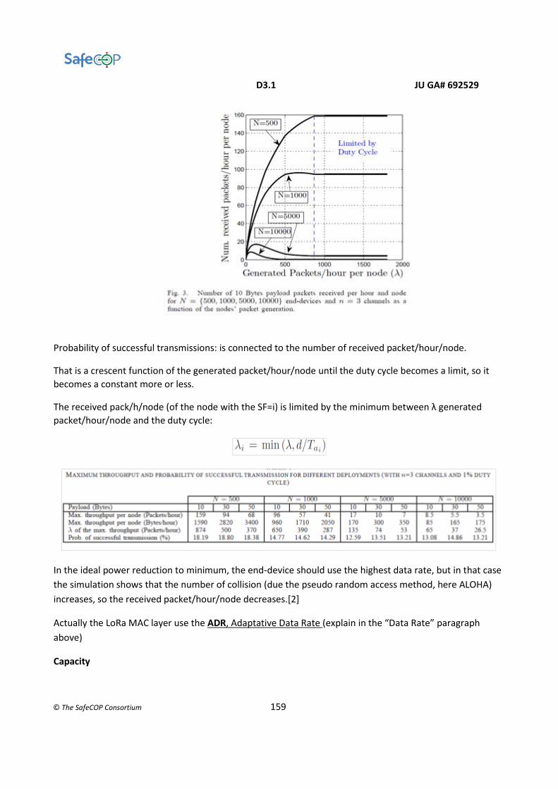
D3.1 JU GA# 692529
© The SafeCOP Consortium 159
Probability of successful transmissions: is connected to the number of received packet/hour/node.
That is a crescent function of the generated packet/hour/node until the duty cycle becomes a limit, so it
becomes a constant more or less.
The received pack/h/node (of the node with the SF=i) is limited by the minimum between λ generated
packet/hour/node and the duty cycle:
In the ideal power reduction to minimum, the end-device should use the highest data rate, but in that case
the simulation shows that the number of collision (due the pseudo random access method, here ALOHA)
increases, so the received packet/hour/node decreases.[2]
Actually the LoRa MAC layer use the ADR, Adaptative Data Rate (explain in the “Data Rate” paragraph
above)
Capacity

D3.1 JU GA# 692529
© The SafeCOP Consortium 160
The capacity of the network is limited by the off-period of ACK frames in the downlink (by the gateway) and
also in the uplink (by the end-devices).
Prospective challenges are:
● minimizing the numbers of ACK frames;
● introducing techniques of fair spectrum sharing between application nodes, due to the congestion of different
vendor application that share the same infrastructure.
IEEE 802.15.4e
DSME also provides additional functionalities like CAP reduction and Group Acknowledgement
(GACK) to improve the QoS delivered to industrial applications. Using CAP reduction, the CAP region of all
the subsequent superframes in the multi-superframe can be replaced with a CFP region. This provides more
GTSs, eventually providing more guaranteed bandwidth and determinism in a larger scale. The following
figure shows the same example depicted before with CAP reduction implemented in it.
Several GTSs transmissions can be acknowledged in DSME using a single GACK. This unique feature helps in
reducing the delay for a packet transmission in a network.