safe bearing capacity evaluation of the bridge site along syafrubesi-rasuwagadhi road, central nepal
TRANSCRIPT
8/8/2019 Safe bearing capacity evaluation of the bridge site along Syafrubesi-Rasuwagadhi road, Central Nepal
http://slidepdf.com/reader/full/safe-bearing-capacity-evaluation-of-the-bridge-site-along-syafrubesi-rasuwagadhi 1/6
INTRODUCTION
The part of this paper is prepared to evaluate the
safe bearing capacity of the soil strata for foundation
of the bridge along the proposed Syafrubesi-
Rasuwagadhi Road in Central Nepal. It lies at an
altitude of 1395 m above mean sea level, at the central
development region of Nepal (Fig.1). The study was
carried out with the detailed exploration of drilling
borehole and necessary field and laboratory tests.
The engineering properties of granular soils from
disturbed samples are correlated with the N valuesobtained from standard penetration test/dynamic cone
penetration test (SPT/DCPT) after necessary
corrections to evaluate the bearing pressure for an
open 6 m size square foundation. A Borehole is drilled
at Chainage K0+159 on the left and right abutments
with depths of 25~30 m. The proposed bridge at this
site lies at steep V-shaped valley formed by the
Bhotekoshi River. There is no influence of
groundwater condition. The ground water level is
existed at 9.60 m and 14.36 m below the ground at
left and right abutments. In addition, the bed rock in
this area is encountered at 33.75 m below the surface.
This delineates that there is no influence of rock on
foundation.
OBJECTIVES AND METHODOLOGIES
The objective of the present study is to determine
the bearing capacity of the strata and recommend the
depth of foundation.
Boreholes were drilled by water flush rotary
drilling method with double tube core barrels. Core
barrels of Nx (2 1/8”-core size) and Bx (1 5/8”-core
size) with respective casings are used. Nx core barrel
is used till it could proceed the drilling smoothly.
Then the borehole size is reduced to Bx size. All the
holes are completed to the size of Bx barrel. Barrels
of 1.5 m length are used for convenient SPT/DCPT
hammering at every 1.5 m depth. The recovered cores
are stored in the standard core boxes of 0.3 m width
Bulletin of the Department of Geology, Tribhuvan University, Kathmandu, Nepal, Vol. 12, 2009, pp. 95–100
Safe bearing capacity evaluation of the bridge site along
Syafrubesi-Rasuwagadhi road, Central Nepal*Suman Manandhar 1, Uttam Bol Shrestha2, Noriyuki Yasufuku1,
Kiyoshi Omine1, and Taizo Kobayashi1
1 Department of Civil and Structural Engineering, Kyushu University, Fukuouka, Japan2 Department of Mines and Geology, Lainchaur, Kathmandu, Nepal
ABSTRACT
The research work was carried out at the proposed bridge site along Syafrubesi-Rasuwagadhi Road, Central Nepal. The study
was based on field SPT/DCPT and laboratory tests. N values were determined from SPT/DCPT test. The index and mechanical
properties of granular soils were computed in laboratory. Then, ultimate and allowable bearing capacities with safety factor 3 for
maximum tolerable limit of 40 mm settlement was estimated by empirical equations provided by Teng (1988) and Terzaghi and
Peck (1978). It is recommended that safe bearing capacity for 6 m size open square foundation at left and right abutments are
suitable within 4.5 to 6 m depth.
*Corresponding author:
E-mail address: [email protected]
Bulletin of the Department of Geology

8/8/2019 Safe bearing capacity evaluation of the bridge site along Syafrubesi-Rasuwagadhi road, Central Nepal
http://slidepdf.com/reader/full/safe-bearing-capacity-evaluation-of-the-bridge-site-along-syafrubesi-rasuwagadhi 2/6
and one metre length with 4 to 5 partition suitable
for Nx and Bx cores, respectively. The recovered soft
and sandy material and collected sludge are placed
in the plastic sample bags before storing in the core
boxes.
Disturbed samples of granular soil were collected
from split spoon sampler obtained during Standard
Penetration Tests. The collected samples were tested
for index and strength properties namely, grading
analysis and hydrometer tests, moist density, dry
density and specific gravity, natural moisture content,
maximum and minimum dry densities, natural angle
of repose, and direct shear tests. Then, soils were
classified according to the Unified Soil Classification
System (USCS) based on Japanese Geotechnical
Standard (JGS). Moist density, dry density and specific
gravity tests of soils were determined on the basis of
Japanese Industrial Standard (JIS) System. Direct
shear tests on soils were tested on the basis of British
Standard (B.S.).
The determined engineering properties of granular
soils from disturbed samples are correlated with the
N values obtained from SPT/DCPT after necessary
corrections. The allowable bearing pressure for an
open square foundation is equal to the ultimate bearing
capacity divided by a factor of safety of 3. The
following empirical equations are used for the open
foundation on granular soils (Teng 1988).
qult = 2N²BR w + 6(100+N²)DR 'w… … … (1)
Where, qult is net ultimate bearing pressure, psf;
N, adjusted standard penetration resistance value; B,
width of footing, ft; D, depth of footing, ft, and Rw
and R'w, correction factor for position of water table.
When water level is below the bottom of footing,
R'w is 1 and when the water level is bottom of footing,
Rw is 0.5 (Fig. 2).
The allowable bearing pressure for open foundation
based on tolerable settlement of 25 mm is given by
the following empirical (Terzaghi and Peck 1978)
relationship.
qa = 720 (N–3) ((B+1)/2B)2 ((B+D)/B)R 'w… (2)
Where, qa is net allowable bearing pressure in psf
for maximum settlement of 25 mm. The allowable
bearing pressure for tolerable settlement of 40 mm
is considered. Therefore,
qa =1.6 x 720 (N–3) ((B+1)/2B)2 ((B+D)/B)R 'w
.........(3)
The bearing capacity of a footing is largely affected
by the characteristics of the volume of soil within a
depth equal to about 1 to 1.5 times the width of the
96
S. Manandhar et al. / Bulletin of the Department of Geology, Vol. 12, 2009, pp. 95–100
Fig. 1 Location map of the study area
0 1 2 Km

8/8/2019 Safe bearing capacity evaluation of the bridge site along Syafrubesi-Rasuwagadhi road, Central Nepal
http://slidepdf.com/reader/full/safe-bearing-capacity-evaluation-of-the-bridge-site-along-syafrubesi-rasuwagadhi 3/6
footing. The bearing capacity of granular soil depends
upon the unit weight and the angle of internal friction
of the soil, both of which vary primarily with the
relative density of the soil. The relative density of granular soils in-situ is generally determined by SPT
or DCPT tests. The dynamic cone resistance is
correlated with the SPT N (Nc) values as given as
1.50 N for depth up to 3.0 m, 1.75 N for depth from
3.0–6.0 m, and 2.0 N for depth greater than 6.0 m.
The relative density of granular soils in-situ is
determined either by standard penetration test or by
dynamic cone penetration test. Because of the extreme
difficulty in obtaining undisturbed samples from
coarse granular soils, the engineering properties of
such soils are determined from disturbed samplesand correlated with the N values obtained from
SPT/CPT after necessary corrections. The correlation
between SPT with the relative density, angle of internal
friction and unit weight of granular soil are shown in
Table 1.
For SPT tests made at shallow depth, the number
of blows is usually too low. At a greater depth, the
same soil with same relative density would give
higher penetration resistance and the weight of
overburden soil on SPT may be approximated by the
following formula.
N = N'(50/(P+10))............(4)
Where, N' and P are actually recorded SPT value
and effective overburden pressure, not exceeding 40
psi respectively.
RESULTS
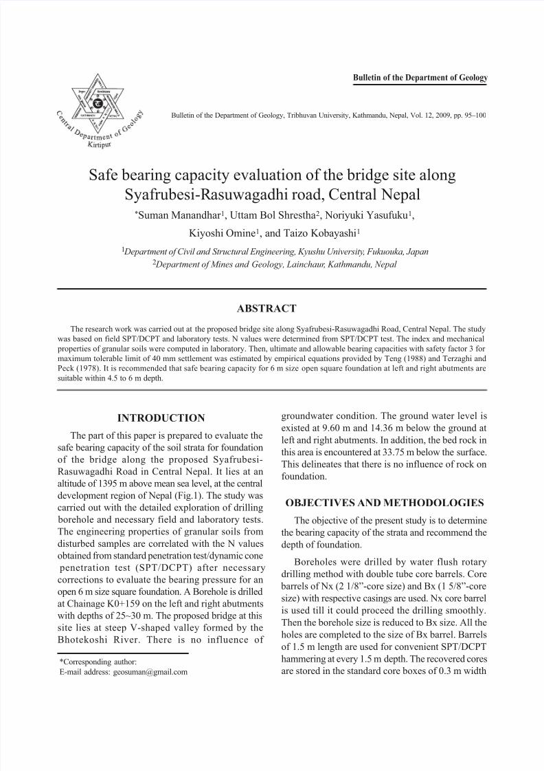
Geotechnical properties at chainage k0+159
The river bank is comprised of alluvial soil,
colluvial soil and mixture of them (Fig. 3). The right
abutment mostly comprises of colluvium, whereas
the left abutment comprises of colluvium underlain
by alluvial terraces of the Bhotekoshi River. Two
boreholes at BHN K0+159 LA and BHN K0+159
RA were drilled at pier location of left and right
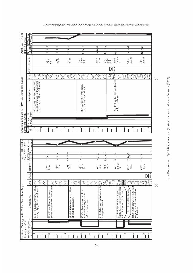
abutments respectively. Fig. 4 (a and b) shows the
borehole log data in order to represent the soil strataas well as N-values.
The borehole BHN K0+159 LA was drilled to a
depth of 30 m where as the borehole BHN K0+159
RA drilled to a depth of 35.75 m. Both boreholes
comprised of boulders and/or cobbles with matrices
of gravel, gravelly sand, and sand. As the depth
increases, the percentage of boulders also increases
on both boreholes. At left abutment, beyond the depth
of 9 m, the boulders dominate the finer materials. At
the right abutment, the stratum of colluvial and alluvial
97
Safe bearing capacity evaluation of the bridge site along Syafrubesi-Rasuwagadhi road, Central Nepal
B
0 0.2 0.4 0.6 0.8 1.0
0.5
1.0
0.6
0.7
0.8
0.9
0.5
1.0
0.6
0.7
0.8
0.9
0 0.2 0.4 0.6 0.8 1.0
Footing
GWL
GWL
d a
d b
h
D
B
(a)
(b) (c)
d a / D d b / B
R w R’w
Fig.2 Correction factor of position of water level: (a) depth of
water level with respect to dimension of footing; (b) water level
above base of footing; (c) water level below base of footing
Table 1 Relationship between Dr, SPT and the Angle of Internal
Friction of Granular Soils (Teng, 1988).
Compact V. Loose Loose Medium Dense V. Dense
Dr , % 0–15 15–35 35–65 65–85 85–100
N/150 blows 0 4 10 30 50
f° 28 30 36 41
1 g t , < 580 550–725 635–750 640–810 > 750kNm-³
2 g
b, < 350 320–375 350–405 380–490 > 435kNm-³
1 g t , moist unit weight,
2 g b , submerged unit weight
8/8/2019 Safe bearing capacity evaluation of the bridge site along Syafrubesi-Rasuwagadhi road, Central Nepal
http://slidepdf.com/reader/full/safe-bearing-capacity-evaluation-of-the-bridge-site-along-syafrubesi-rasuwagadhi 4/6
98
S. Manandhar et al. / Bulletin of the Department of Geology, Vol. 12, 2009, pp. 95–100
mixed soil were found to contain finer material more
than very coarse grained soil. The alluvial soil soil
predominately consists of fine grained soil with some
very coarse grained material. Since, the borehole of
right abutment is located at the hillslope, trenches
have been driven to depth of 4.5 m from the surface
to collect samples. Table 2 summaries the geotechnical
properties of the site.
Bearing capacity analysis of chainage k0+159
Bearing capacity analyses for strata up to 12 m
for left abutment and 13.5 m depth for right abutment
for 6 m size of open square foundation are calculated
for ultimate strength with consideration of 40 mm
allowable settlement. Hence, computed safe bearing
capacities are shown detail in Tables 3 and 4. The
Table 2 Geotechnical Properties of BHN K0+159 LA and BHN K0+159 RA
Depth w r Angle of
(m) (%) t/m³ Repose
rdmax rdmin ° c, N/cm2 °
0.0–1.5 S0Gap graded sandy
gravel0.879 2.67 1.257 1.018 0.924 36.3 - -
3.0–4.5 S0Gap graded sandy
gravel3.816 2.676 1.423 1.253 1.174 37.3 - -
1.5–1.95 S1 Well graded sand(SW)
13.983 2.686 1.6 1.389 1.292 33.7 0 32
10.3–10.65 S2Gap graded
gravelly sand19.857 2.665 1.469 1.287 1.204 33.3 0 33
0.0–1.5 S0Gap graded sandy
gravel3.365 2.67 1.257 1.018 0.924 - - -
3.0–4.5 S0Gap graded sandy
gravel1.135 2.665 1.354 1.24 1.185 - - -
6.0–6.45 S1Gap graded sand
with some fines25.202 2.658 1.43 1.1 0.965 33.7 0 35
10.5–10.95S2
Uniformly graded
sand (SP)29.748 2.682 1.433 1.179 1.08 36.3 0 38
16.5–16.95 S3 Gap graded sand 19.118 2.697 1.481 1.283 1.201 33.7 0 34
30.6–33.35 S4 Gap graded sand 21.738 2.655 1.445 1.165 1.066 35.3 0 34
Borehole
Sample
No.Description G
s
rd Shear
t/m³ Results
B H N K 0 + 1 5 9 L A
B H N K 0 + 1 5 9 R A
f
Fig. 3 A geological map and cross-section
8/8/2019 Safe bearing capacity evaluation of the bridge site along Syafrubesi-Rasuwagadhi road, Central Nepal
http://slidepdf.com/reader/full/safe-bearing-capacity-evaluation-of-the-bridge-site-along-syafrubesi-rasuwagadhi 5/6
99
L
o c a t i o n : C h a i n a g e K 0 + 1 5 9 R A , S y a f r u b e s i ,
N e p a l
E
l e v a t i o n : 1 3 9 5 m
D
e p t h
m
D e p t h : 0 . 0 - 1 4 . 0
m
D a t e : 2 0 0 5 / 1 2 / 0 1
R e c o v e r y %
D e s c r i p t i o n s
L o g G W L S a m p l e
1 5 c m 1 5
1 5
c m c m
S P T N S P T i n T o
t a l
0 1 0
2 0
3 0 4
0 5 0
0
2 0 4 0 6 0
8 0 1 0 0
( 0 - 1 . 5 ) s i l t y s a n d w i t h f e w c o b
b l e s ,
m a i n l y o f p h y l l i t i c r o c k ( c o l l u v
i u m )
( 1 . 5 - 4 . 3 5 ) c o b b l e s w i t h s o m e
g r a v e l l y s a n d a n d s i l t ( c o l l u v i u m )
( 4 . 3 5 - 5 . 6 5 ) b o u l d e r s a n d c o b b l e s
o f p h y l l i t e ( c o l l u v i u m )
( 5 . 6 5 - 8 . 0 ) g r e y , m e d i u m d e n s e
s a n d w i t h s o m e g r a v e l s a n d
c o b b l e s ( c o l l u v i u m )
( 8 - 1 0 . 3 ) b o u l d e r s a n d c o b b l e s
w i t h
l i t t l e g r a v e l l y s a n d
( 1 0 . 4 - 1 1 . 2 ) m e d i u m c o m p a c
t
h i g h l y m i c a c e o u s s i l t y f i n e s a n d
w i t h l i t t l e g r a v e l ( c o l l u v i u m
)
( 1 1 . 2 - 1 1 . 8 ) p h y l l i t i c b o u l d
e r
( 1 1 . 8 - 1 4 . 2 5 ) g r e y , d e n s e s i l t y
s a n d
a n d g r a v e l w i t h s o m e c o b b l e s
( c o l l u v i u m )
S P T
C P T
C P T
S P T
S P T
C P T
S P T
C P T
C P T
0 1 2 3 4 5 6 7 8 9 1 0 1 1 1 2 1 3
1 5 2 0 1 3
1 4 1 8 1 0
R e j - r o c k
1 6 1 8 1 2
1 8 2 1 2 3
R e j - r o c k
1 3 5
7
1 5 R e j - 7
R e j - 1 3
1 4
1 4 . 3 6 m
- - -
1 . 5 m
3 . 0 m
4 . 5 m
6 . 0 m
7 . 5 m
9 . 0 m
1 0 . 5 m
1 2 . 0 m
1 3 . 5 m
S - 1
S - 2
L o c a t i o n : C h a i n a g e K 0 + 1 5 9 L A , S y a f r u b e s i , N e p a l
E l e v a t i o n : 1 3 9 6 m
D e p t h
m
D e p t h :
0 . 0 - 1 4 . 0 m
D a t e : 2 0 0 5 / 1 2 / 0 1
R e c o v e r y %
D e s c r i p t i o n s
L o g G W L S a m p l e
1 5 c m 1 5
1
5
c m c m
S P T N
S P T i n T o t a l
0 1 0
2 0 3 0 4 0 5 0
0
2 0 4 0 6 0 8 0 1 0 0
( 0 - 5 . 4 ) g r e y m e d i u m d e n s e , f i n e t o
m e d i u m g r a i n e d s
a n d w i t h s o m e
g r a v e l s a n d c o b b l e s ( C o l l u v i u m )
( 5 . 4 - 9 . 0 ) c o b b l e s w i t h d e n s e ,
g r a v e l l y s a n d ( c o l l u v i u m )
( 9 . 0 - 1 4 ) b o u l d e r s a n d c o b b l e s w i t h
l i t t l e g r a v e l l y s a n d
S P T
C P T
C P T
C P T
C P T
C P T
C P T
C P T
C P T
0 1 2 3 4 5 6 7 8 9 1 0 1 1 1 2 1 3
1 2 1 5 1 5
1 2 1 8 1 5
R e j - 7
1 3 4 R e j - r o c k
R e j - 1 0
R e j - r o c
k
1 4
9 . 6 5 m
1 . 5 m
S - 1 3
. 0 m
4 . 5 m
6 . 0 m
7 . 5 m
9 . 0 m
R - 1 S - 2
1 0 . 5 m
1 2 . 0 m
1 3 . 5 m
S - 1
S - 2
3 9 1 0 1 5
R e j - 7
R e j - r o c k
Safe bearing capacity evaluation of the bridge site along Syafrubesi-Rasuwagadhi road, Central Nepal
F i g . 4 B o r e h o l e l o g o f ( a ) l e f t a b u
t m e n t a n d ( b ) r i g h t a b u t m e n t r e d r a w n a f t e r A n o n ( 2 0 0 7 )
( a )
( b )

8/8/2019 Safe bearing capacity evaluation of the bridge site along Syafrubesi-Rasuwagadhi road, Central Nepal
http://slidepdf.com/reader/full/safe-bearing-capacity-evaluation-of-the-bridge-site-along-syafrubesi-rasuwagadhi 6/6
100
S. Manandhar et al. / Bulletin of the Department of Geology, Vol. 12, 2009, pp. 95–100
ground levels were encountered at depths of 9.60 m
and 14.3 m respectively. Since, the topography of
right abutment is very steep, only 50 % of the safe
bearing capacity given in Table 4 should be considered
for foundation.
CONCLUSIONS
Since the topography of the area is very steep, the
bearing stratum recommends that only 50% of the
safe bearing capacity should be considered for
foundation given above in the table. In addition, there
are no influences of groundwater and deep seated
rock formation. The study shows that all the strata
below 4.5 m has safe bearing capacity of more than
100 t/m2, the bearing stratum at the depth of 4.5 to
6 m seems to be enough for a load up to 50 t/m 2 at
left abutment. In addition, the bearing capacity of the
strata at 10.5 m has lower bearing capacity of than
the upper strata at right abutment. Therefore, the open
6 m size square foundation is recommended at the
depth of 4.5 to 6 m.
REFERENCES
Anon, 2007. Report on Soil Investigation of Proposed
BridgeSites along Syafrubesi-Rasuwagadhi Road:Submitted to Syafrubesi - Rasuwagadhi Road Project,Department of Roads, Ministry of Physical Planning
and Works Babarmahal, Kathmandu, Nepal(unpublished).
Teng, W.C., 1988. Foundation Design, Prentice Hall of India.
Terzaghi, K. and Peck, R.B., 1978. Soil Mechanics in
Foundation Engineering, John Wiley and Sons Inc.
D qult
5qa` 6q
s
m R w R’ w t/m² t/m² t/m²
3 1.00 1.00 33 184 70 70
4.5 1.00 0.92 25 136 60 60
6 1.00 0.80 50 559 116.70 117
7.5 1.00 0.67 50 578 110.00 110
9 1.00 0.55 50 572 100.30 100
10.5 0.96 0.50 50 591 100.30 100
12 0.90 0.50 50 643 109.40 109
3GWCF 4C-SPT,
N-Value
3GWCF (Ground water correction factor), 4C-SPT (corrected-SPT), 5qa`(Allowable bearing capacity based
on 40 mm settlement), 6qs (Safe bearing capacity)
Table 3: Bearing Capacity of foundation of 6 m size K0+159 LA
Table 4: Bearing Capacity of foundation of 6 m size K0+159 RA
D qult
5qa` 6q
sm R
wR’
wt/m² t/m² t/m²
3 1.00 1.00 19 67.4 37.20 37
4.5 1.00 1.00 50 534.9 127.60 128
6 1.00 1.00 30 250.0 83.80 84
7.5 1.00 1.00 46 668.0 150.00 150
9 1.00 0.88 50 819.0 160.00 160
10.5 100.00 0.82 22 192.0 66.50 66
12 1.00 0.68 50 839.0 148.80 149
13.5 1.00 0.58 50 812.0 137.50 138
3GWCF 4C-SPT,
N-Value