sae j1349 / 71 hp 0.30 - 0.59 m (0.39 - 0.77 yd ) 13,495 ... x-leg type center frame is integrally...
TRANSCRIPT

01
ENGINE
Maker / Model Perkins 854F
Type Water cooled, 4 cycle Diesel,4-cylinders in line, direct injection,turbocharged charger and air cooled.
Rated fl ywheel horse power
SAEJ1995 (gross) 73.6 HP (55 kW) / 2,200 rpm
J1349 (net) 71 HP (53 kW) / 2,200 rpm
Max. torque 43.2 kgf.m (313 lbf.ft) / 1,200 rpm
Bore X stroke 99 x 110 mm (3.89” x 4.33”)
Piston displacement 3,400 cc (207 in3)
Batteries 2 x 12 V x 100 Ah
Starting motor 24 V - 4.5 kW
Alternator 24 V - 65 Amp
HYDRAULIC CYLINDERS
No. of cylinderbore X stroke
Boom: 2-95 x 1,015 mm (3.74” x 40”)
Arm: 1-110 x 1,070 mm (4.3” x 42.1”)
Bucket: 1-100 x 855 mm (3.9” x 33.7”)
Blade: 2-100 x 240 mm (3.9” x 9.4”)
DRIVES & BRAKES
Drive method Fully hydrostatic type
Drive motor Axial piston motor, in-shoe design
Reduction system Planetary reduction gear
Max. drawbar pull 11,400 kgf (25,100 lbf)
Max. travel speed (high / low) 5.5 km/hr (3.4 mph) / 3.3 km/hr (2.1 mph)
Gradeability 35° (70%)
Parking brake Multi wet disc
RELIEF VALVE SETTINGImplement circuits 330 kgf/cm2 (4,690 psi)
Travel 330 kgf/cm2 (4,690 psi)
Power boost (boom, arm, bucket) 360 kgf/cm2 (5,120 psi)
Swing circuit 285 kgf/cm2 (4,050 psi)
Pilot circuit 40 kgf/cm2 (570 psi)
Service valve Installed
CROSS-SENSING AND FUEL-SAVING PUMP SYSTEMHYDRAULIC MOTORS
TravelTwo speed axial pistons motor with brake valve and parking brake
Swing Axial piston motor with automatic brake
HYDRAULIC SYSTEM
MAIN PUMP
TypeVariable displacement tandem axis piston pumps
Max. fl ow 2 x 126 ℓ/min (33.3 US gpm)
Sub-pump for pilot circuit Gear pump
CONTROL
Pilot pressure operated joysticks and pedals with detachable lever provide almost effortless and fatigueless operation.
Pilot controlTwo joysticks with one safety lever(LH): Swing and arm(RH): Boom and bucket (ISO)
Traveling and steering Two levers with pedals
Engine throttle Electric, dial type
SWING SYSTEM
Swing motor Fixed displacement axial piston motor
Swing reduction Planetary gear reduction
Swing bearing lubrication Grease-bathed
Swing brake Multi wet disc
Swing speed 12.6 rpm
SERVICE REFILL CAPACITIES
Re-fi lling liter US gal
Fuel tank 240 63.4
Engine coolant 20 5.3
Engine oil 8.0 2.1
Swing device 2.5 0.7
Final drive (each) 2.3 0.6
Hydraulic system (including tank) 160 42.3
Hydraulic tank 96 25.4
DEF/AdBlue® tank 19 5.0
UNDERCARRIAGE
The X-leg type center frame is integrally welded with reinforced box-section track frames. The undercarriage includes lubricated rollers, idlers, track adjusters with shock absorbing springs and sprockets, and a track chain with double or triple grouser shoes.
Center frame X - leg type
Track frame Pentagonal box type
No. of shoes on each side 43 EA
No. of carrier roller on each side 1 EA
No. of track roller on each side 6 EA
No. of rail guard on each side 1 EA
OPERATING WEIGHT (APPROXIMATE)
Operating weight, including 4,300 mm (14’ 1”) boom, 2,810 mm (9’ 3”) arm, SAE heaped 0.40 m3 (0.52 yd3) bucket, lubricant, coolant, full fuel tank, full hydraulic tank, and all standard equipment.
OPERATING WEIGHT
Shoes Operating weightGround pressure
TypeWidth mm (in)
kg (lb) kgf/cm2 (psi)
Triple grouser
600 (24”)HX130LCR 13,495 (29,750) 0.37 (5.26)
HX130LCR (Dozer type) 14,195 (31,290) 0.39 (5.54)
700 (28”)HX130LCR 13,655 (30,100) 0.32 (4.55)
HX130LCR (Dozer type) 14,355 (31,650) 0.34 (4.83)
HX130LCRTier 4 Final Engine
SPECIFICATIONS Net PowerSAE J1349 / 71 HP (53 kW) at 2,200 rpm
Operating Weight13,495 kg (29,750 lb)
Bucket Range0.30 - 0.59 m3 (0.39 - 0.77 yd3)Standard Bucket0.40 m³ (0.52 yd³)
D
E
B B' C
A
A'
F
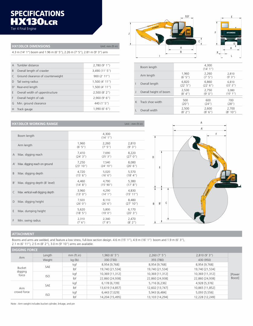
HX130LCR DIMENSIONS Unit: mm (ft·in)
4.3 m (14’ 1”) boom and 1.96 m (6’ 5”), 2.26 m (7’ 5”), 2.81 m (9’ 3”) arm
A
B
D,D'
I
C
J F
E
G
H
LK
HX130LCR
Boom length4,300
(14’ 1”)
Arm length1,960(6’ 5”)
2,260(7’ 5”)
2,810(9’ 3”)
A Max. digging reach 7,410(24’ 3”)
7,690(25’ 3”)
8,220(27’ 0”)
A’ Max. digging reach on ground 7,250(23’ 10”)
7,540(24’ 10”)
8,080(26’ 6”)
B Max. digging depth 4,720(15’ 6”)
5,020(16’ 6”)
5,570(18’ 4”)
B’ Max. digging depth (8' level) 4,460(14’ 8”)
4,790(15’ 90”)
5,380(17’ 8”)
C Max. vertical wall digging depth 3,960(13’ 0”)
4,290(14’ 1”)
4,830(15’ 11”)
D Max. digging height7,920
(26’ 0”)8,110
(26’ 6”)8,480
(27’ 10”)
E Max. dumping height 5,620(18’ 5”)
5,800(19’ 0”)
6,170(20’ 3”)
F Min. swing radius2,310(7’ 6”)
2,340(7’ 8”)
2,470(8’ 2”)
A Tumbler distance 2,780 (9' 1")
B Overall length of crawler 3,490 (11' 5")
C Ground clearance of counterweight 900 (2’ 11”)
D Tail swing radius 1,500 (4’ 11”)
D’ Rear-end length 1,500 (4’ 11”)
E Overall width of upperstructure 2,500 (8’ 2”)
F Overall height of cab 2,900 (9’ 6”)
G Min. ground clearance 440 (1’ 5”)
H Track gauge 1,990 (6’ 6”)
Boom length4,300
(14’ 1”)
Arm length1,960(6’ 5”)
2,260(7’ 5”)
2,810(9’ 3”)
I Overall length6,820
(22’ 5”)6,860
(22’ 6”)6,810
(22’ 2”)
J Overall height of boom2,530(8’ 4”)
2,750(9’ 0”)
3,080(10’ 1”)
K Track shoe width500(20”)
600(24”)
700(28”)
L Overall width2,500(8’ 2”)
2,600(8’ 6”)
2,700(8’ 10”)
ATTACHMENT
Booms and arms are welded, and feature a low stress, full-box section design. 4.6 m (15’ 1”), 4.9 m (16’ 1”) boom and 1.9 m (6’ 3”), 2.1 m (6’ 11”), 2.5 m (8’ 2”), 3.0 m (9’ 10”) arms are available.
DIGGING FORCE
ArmLength mm (ft.in) 1,960 (6’ 5”) 2,260 (7’ 5”) 2,810 (9’ 3”)
[Power Boost]
Weight kg (lb) 330 (730) 355 (780) 430 (950)
Bucketdiggingforce
SAEkgf 8,954 [9,768] 8,954 [9,768] 8,954 [9,768]
lbf 19,740 [21,534] 19,740 [21,534] 19,740 [21,534]
ISOkgf 10,369 [11,312] 10,369 [11,312] 10,369 [11,312]
lbf 22,860 [24,938] 22,860 [24,938] 22,860 [24,938]
Armcrowd force
SAEkgf 6,178 [6,739] 5,716 [6,236] 4,928 [5,376]
lbf 13,619 [14,857] 12,602 [13,747] 10,865 [11,852]
ISOkgf 6,443 [7,029] 5,943 [6,484] 5,093 [5,556]
lbf 14,204 [15,495] 13,103 [14,294] 12,228 [12,249]
Note : Arm weight includes bucket cylinder, linkage, and pin
HX130LCR WORKING RANGE Unit : mm (ft·in)

Load pointheight(m / ft)
Load radius At max. reach
1.5 m (4.9 ft) 3.0 m (9.8 ft) 4.5 m (14.8 ft) 6.0 m (19.7 ft) Capacity Reach
m (ft)
6.0 m kg *2,460 *2,460 *1,760 *1,760 5.36
(20 ft) lb *5,420 *5,420 *3,880 *3,880 (17.6)
4.5 m kg *2,550 *2,550 *2,380 2,280 *1,600 *1,600 6.34
(15 ft) lb *5,620 *5,620 *5,250 5,030 *3,530 *3,530 (20.8)
3.0 m kg *3,820 *3,820 *3,210 *3,210 *2,980 2,230 *1,570 *1,570 6.86
(10 ft) lb *8,420 *8,420 *7,080 *7,080 *6,570 4,920 *3,460 *3,460 (22.5)
1.5 m kg *6,270 6,210 *4,150 3,310 *3,380 2,150 *1,650 *1,650 7.03
(5 ft) lb *13,820 13,690 *9,150 7,300 *7,450 4,740 *3,640 *3,640 (23.1)
Ground kg *7,830 5,830 *4,940 3,140 *3,740 2,080 *1,830 1,710 6.86
Line lb *17,260 12,850 *10,890 6,920 *8,250 4,590 *4,030 3,770 (22.5)
-1.5 m kg *4,170 *4,170 *8,140 5,720 *5,260 3,070 *3,830 2,050 *2,210 1,900 6.34
(-5 ft) lb *9,190 *9,190 *17,950 12,610 *11,600 6,770 *8,440 4,520 *4,870 4,190 (20.8)
-3.0 m kg *7,330 *7,330 *7,430 5,780 *4,880 3,090 *3,140 2,430 5.36
(-10 ft) lb *16,160 *16,160 *16,380 12,740 *10,760 6,810 *6,920 5,360 (17.6)
NOTES:1. Lifting capacities are based on ISO 10567.2. Lifting capacity of the HX Series does not exceed 75% of tipping load with the machine on firm, level ground or 87% of full hydraulic capacity.
3. The Lift-point is bucket pivot mounting pin on the arm (without bucket mass).4. (*) indicates load limited by hydraulic capacity.
Lifting CapacityBoom: 4.3 m (14’ 1”) Capacities based on North American Standard
Configuration in accordance with ISO condition 2 standard.Arm: 2.81 m (9’ 3”)Bucket: 0.40 m3 (0.52 yd³) SAE heaped Rating over frontShoe 500 mm (20”) triple grouser, CWT 2,350 kg (5,181 lb) Rating over side or 360 degree
BUCKETS
All buckets are welded with high-strength steel.
Capacitym3 (yd3)
Widthmm (in) Weight
kg (lb)
Recommendation mm (ft•in)
4,300 (14’ 1”) Boom
SAEHeaped
CECEHeaped
WithoutSide Cutters
WithSide Cutters
1,960 (6’ 5”) Arm 2,260 (7’ 5”) Arm 2,810 (9’ 3”) Arm
0.30 (0.39) 0.27 (0.35) 610 (24.0) 720 (28.3) 360 (790)
0.40 (0.52) 0.44 (0.58) 760 (29.9) 870 (34.3) 410 (900)
0.45 (0.59) 0.40 (0.52) 830 (32.7) 940 (37.0) 430 (950)
0.50 (0.65) 0.45 (0.59) 900 (35.4) 1,010 (39.8) 450 (990)
0.59 (0.77) 0.52 (0.68) 1,020 (40.2) 1,130 (44.5) 490 (1,080) –
SAE Heapedm3 (yd3) 0.30 (0.39) 0.40 (0.52) 0.45 (0.59) 0.50 (0.65) 0.59 (0.77)
: Applicable for materials with density of 2,000 kgf/m3 (3,370 lbf/yd3) or less
: Applicable for materials with density of 1,600 kgf/m3 (2,700 lbf/yd3) or less
: Applicable for materials with density of 1,100 kgf/m3 (1,850 lbf/yd3) or less
HX130LCR

1074-EX-SP_2/2018v18
PLEASE CONTACT
ENGINE STD OPT
Perkins 854F Engine •
HYDRAULIC SYSTEMIntelligent Power Control (IPC)
3-power mode, 2-work mode, user mode •Variable power control •Pump fl ow control •Attachment mode fl ow control •Engine auto idle •Engine auto shutdown control •Electronic fan control •
CAB & INTERIORISO Standard cabin
Rise-up type windshield wiper •Radio/USB player •Handsfree mobile phone system with USB •12 volt power outlet (24 V DC to 12 V DC converter) •Electric horn •All-weather steel cab with 360° visibility •Safety glass windows •Sliding fold-in front window •Sliding side window (LH) •Lockable door •Storage compartment & ashtray •Transparent cabin roof-cover •Sun visor •Door and cab locks, one key •Pilot-operated adjustable joystick •Console box height adjust system •Smart start with key fob •Cabin lights •Cabin front window rain guard •
Automatic climate controlAir conditioner & heater •Defroster •Starting Aid (air grid heater) for cold weather •
Centralized monitoring8" LCD display •Engine speed or trip meter/accelerator •Engine coolant temperature gauge •Max power •Low speed/High speed •Auto idle •Overload •Check engine •Air cleaner clogging •Indicators •ECO gauges •Fuel level gauge •Hydraulic oil temperature gauge •Warnings •Communication error •Low battery •Clock •
CAB & INTERIOR STD OPT
SeatAdjustable air suspension seat with heater •
Cabin FOPS/FOG (ISO/DIS 10262) Level 2FOPS (Falling Object Protective Structure)·ISO 3,449 Level 2 •FOG (Falling Object Guard) •
Cabin ROPS (ISO 12117-2)ROPS (Roll Over Protective Structure) •
SAFETY STD OPT
Battery master switch •Rearview camera •AAVM (All-Around View Monitoring) •Four front working lights (2 boom mounted, 2 front frame mounted) •Travel alarm •Rear work lamp •Beacon lamp LED •Automatic swing brake •Boom holding system •Arm holding system •Safety lock valve for boom cylinder with overload warning device •Safety lock valve for arm cylinder •Swing lock system •Two outside rearview mirror •
Wirenet guard •
OTHERBooms
4.3 m, 14' 1" •Arms
1.96 m, 6' 5" •2.26 m, 7' 5" •2.81 m, 9’ 3” •
Removable clean-out dust net for cooler •Removable reservoir tank •Fuel pre-filter •Self-diagnostics system •
Hi-mate (Remote Management System) Mobile •Satellite •
Batteries (2 x 12 V x 100 Ah) •Fuel filler pump (50 ℓ/min) •Double-acting piping kit (clamshell, etc.) with proportional control •Rotating piping kit with proportional control •Hyundai dual-lock quick coupler with piping •Accumulator for lowering work equipment •Pattern change valve (2 patterns) •Fine swing control system •Heavier counterweight 5,180 lbs/ 2,350 kg •
UNDERCARRIAGELower frame under cover (Normal) •Track shoes
Triple grousers shoes (500 mm, 20") •Triple grousers shoe (600 mm, 24") •Triple grousers shoe (700 mm, 28") •Road liner track shoes (500 mm, 20”) •
* Standard and optional equipment may vary. Contact your Hyundai dealer for more information. The machine may vary according to International standards.* The photos may include attachments and optional equipment that are not available in your area.* Materials and specifications are subject to change without advance notice.* All imperial measurements rounded off to the nearest pound or inch.
www.hceamericas.com6100 Atlantic Blvd., Norcross, GA 30071TEL (678) 823 7777 FAX (678) 823 7778
Made in the U.S.A.
HX130LCR