saas umg 509-pro - janitza electronics · umg 509-pro • continuous monitoring of the power...
TRANSCRIPT
UMG 509-PRO
Alarm management
Power quality
Graphicprogramming
Ethernet connection Ethernet-Modbus gateway
Residual current monitoring
RCM
4 MB
64Channels
FCO
O
Ethernetanschluß Ethernet-Modbus-Gateway
Impulsaus- undImpulseingänge
GridVis®
GridVisReporting AlarmmanagementGraphen
GridVIS
Allgemein E
RCM
PQ
Technische Daten
www
Homepage
Jasic
Jasic
Einsatzgebiete
BACnet
BACnet
MID
MID
Allgemein A
Allgemein B
Allgemein C
Farbiges Grafikdisplay
Benutzerverwaltung
1 2 3
Abmessungen
Ereignisse
Flicker
Class A..-4-30
Class A..-4-30
Spannungsqualität
29. 40. 63.
Oberschwingungen
4Tariffs
7Tariffs
8Tariffs
Tarife
Class0,2 kWh
Class0,5 kWh
Class1,0 kWh
Messgenauigkeit
Modbus
Transienten
32 MB 128 MB 256 MB
Datenspeicher
512 K
14Tariffs
25.
Grenzwertüberwachung
1Tariffs
2Tariffs
CO
Temperatureingang
Emax
®
SaaS
SaaS
M-Bus
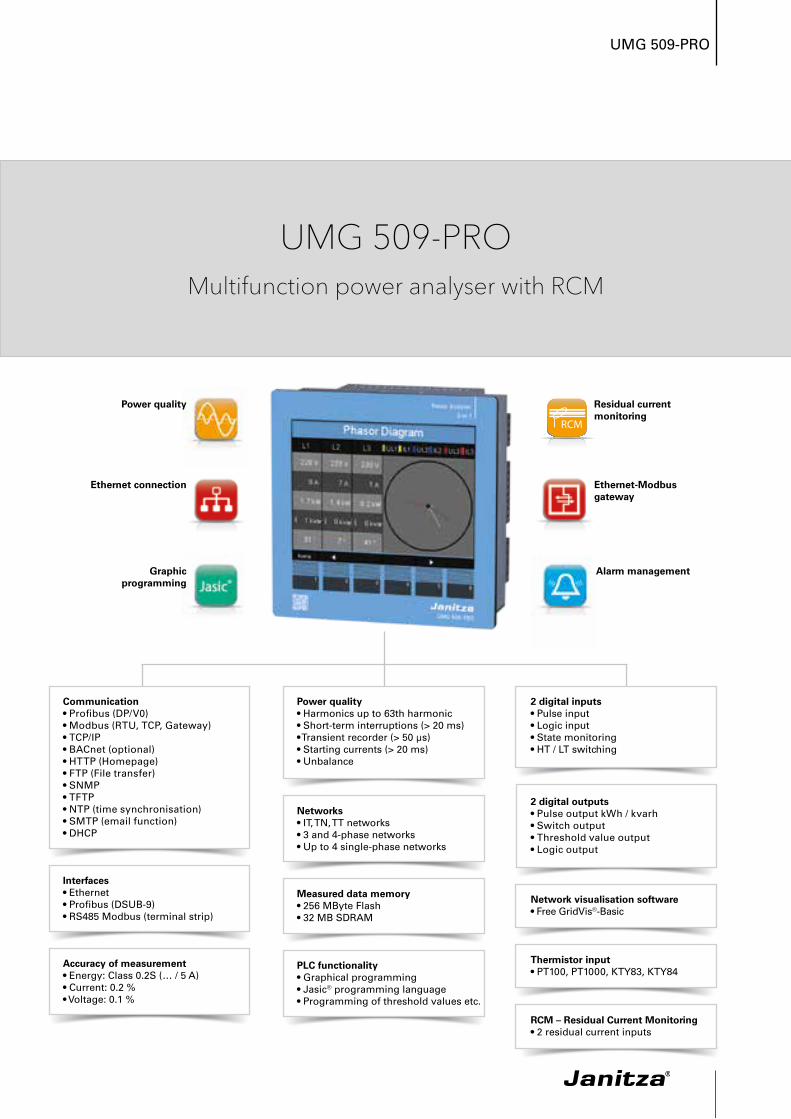
2 digital outputs• Pulse output kWh / kvarh• Switch output• Threshold value output• Logic output
2 digital inputs• Pulse input• Logic input• State monitoring• HT / LT switching
Network visualisation software• Free GridVis®-Basic
Interfaces• Ethernet• Profibus (DSUB-9)• RS485 Modbus (terminal strip)
Communication• Profibus (DP/V0)• Modbus (RTU, TCP, Gateway)• TCP/IP• BACnet (optional)• HTTP (Homepage)• FTP (File transfer)• SNMP• TFTP• NTP (time synchronisation)• SMTP (email function)• DHCP
Accuracy of measurement• Energy: Class 0.2S (… / 5 A)• Current: 0.2 %• Voltage: 0.1 %
Networks• IT, TN, TT networks• 3 and 4-phase networks• Up to 4 single-phase networks
Measured data memory• 256 MByte Flash• 32 MB SDRAM
Power quality • Harmonics up to 63th harmonic• Short-term interruptions (> 20 ms)• Transient recorder (> 50 μs)• Starting currents (> 20 ms)• Unbalance
PLC functionality• Graphical programming• Jasic® programming language• Programming of threshold values etc.
RCM – Residual Current Monitoring• 2 residual current inputs
Thermistor input• PT100, PT1000, KTY83, KTY84
UMG 509-PROMultifunction power analyser with RCM
UMG 509-PRO
• Continuous monitoring of the power quality• Energy management systems (ISO 50001)• Master device with Ethernet gateway for subordinate
measurement points• Visualisation of the energy supply in the LVDB• Analysis of electrical disturbances in the event of
power quality problems• Cost centre analysis• Remote monitoring in the property operation• Use in test fields (e.g. in universities)
Areas of application
Main features
High quality measurement with high sampling rate (20 kHz per channel)
Power quality
• Harmonics analysis up to 63rd harmonic• Acquisition of short-term interruptions• Acquisition of transients• Display of waveforms (current and voltage)• Unbalance• Vector diagram
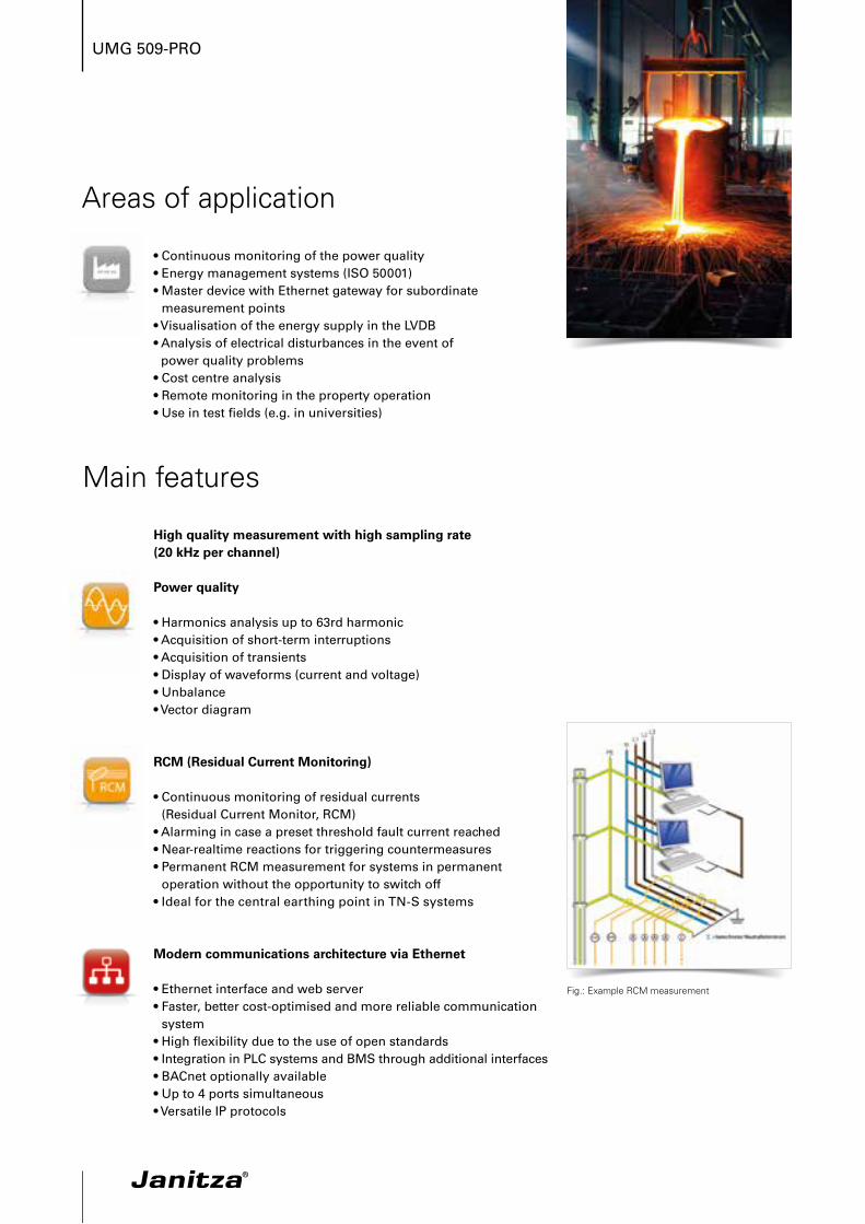
RCM (Residual Current Monitoring)
• Continuous monitoring of residual currents(Residual Current Monitor, RCM)
• Alarming in case a preset threshold fault current reached• Near-realtime reactions for triggering countermeasures• Permanent RCM measurement for systems in permanent
operation without the opportunity to switch off• Ideal for the central earthing point in TN-S systems
Modern communications architecture via Ethernet
• Ethernet interface and web server• Faster, better cost-optimised and more reliable communication
system• High flexibility due to the use of open standards• Integration in PLC systems and BMS through additional interfaces• BACnet optionally available• Up to 4 ports simultaneous• Versatile IP protocols
Fig.: Example RCM measurement
UMG 509-PRO
Modbus Gateway function
• Economical connection of devices without Ethernet interface• Integration of devices with Modbus-RTU interface possible• Data can be scaled and described• Minimised number of IP addresses required
Graphical programming
• Comprehensive programming options (PLC functionality)• Jasic® source code programming• Sustainable functional expansions far beyond pure
measurement• Complete APPs from the Janitza library
Powerful alarm management
• Can be programmed via the graphic programming or Jasic®
source code• All measured values can be used• Can be arbitrarily, mathematically processed• Individual forwarding via email sending, switching of digital
outputs, writing to Modbus addresses etc.• Watchdog APPs• Further alarm management functions via GridVis®-Service alarm
management
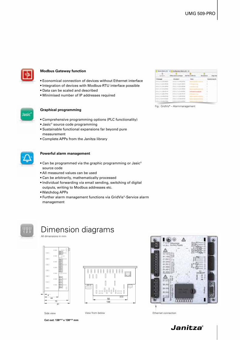
Dimension diagramsAll dimensions in mm
Side view View from below Ethernet connection
Cut out: 138+0,8 x 138+0,8 mm
Fig.: GridVis® – Alarmmanagement
UMG 509-PRO
A +
-
1
PE
N
L1
V1 V2 V3 V4
Spannungsmessung 1-4Voltage Input 1-4
27 28 29 30
L2
Strommessung 1-4Current Input 1-4
S1 S2
S1
S1
S2
S2
S1 S2
S1 S2
I1
19 20S1 S2
I2
21 22S1 S2
I3
23 24S1 S2
I4
25 26
VN
31
L3
HilfsenergieAuxiliary Supply
17 18
L/+ N/-PE
Verb
rauc
her
Load
s
PE
N
L1
RS485
B
8 9 10
Temp.
PT100IPEIDIFF
0-30 mA
4 5 6 7
RCM
I5 I611 12 13
DigitalOutputs
K1
K2
14 15 16
DigitalInputs
2
Ethe
rnet
10/1
00B
ase-
T
RJ4
5 Switch
PCPC
Pro
fibus
DS
UB
-9
SPS
SPS
2 3A B
1
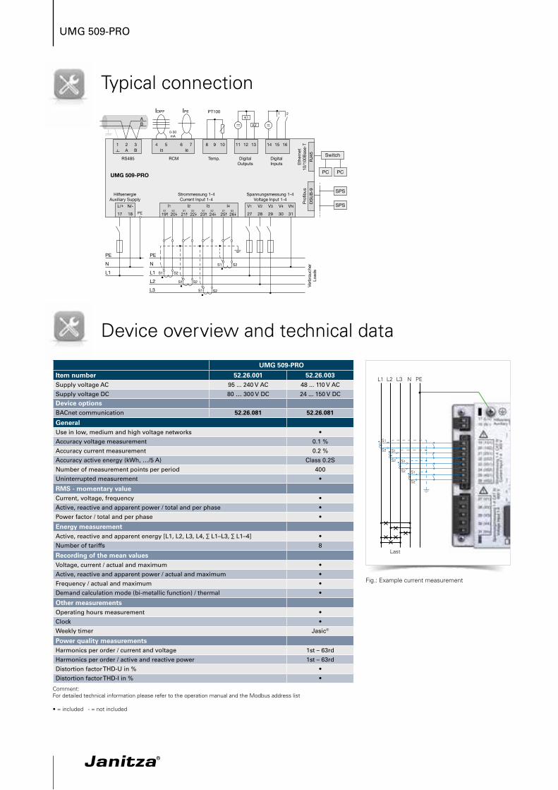
UMG 509-PRO
Typical connection
Device overview and technical data
Fig.: Example current measurement
GeneralUse in low, medium and high voltage networks •Accuracy voltage measurement 0.1 %Accuracy current measurement 0.2 %Accuracy active energy (kWh, …/5 A) Class 0.2SNumber of measurement points per period 400Uninterrupted measurement •
RMS - momentary valueCurrent, voltage, frequency •Active, reactive and apparent power / total and per phase •Power factor / total and per phase •
Energy measurementActive, reactive and apparent energy [L1, L2, L3, L4, ∑ L1–L3, ∑ L1–4] •Number of tariffs 8
Recording of the mean valuesVoltage, current / actual and maximum •Active, reactive and apparent power / actual and maximum •Frequency / actual and maximum •Demand calculation mode (bi-metallic function) / thermal •
Other measurementsOperating hours measurement •Clock •Weekly timer Jasic®
Power quality measurementsHarmonics per order / current and voltage 1st – 63rdHarmonics per order / active and reactive power 1st – 63rdDistortion factor THD-U in % •Distortion factor THD-I in % •
Comment: For detailed technical information please refer to the operation manual and the Modbus address list
• = included - = not included
S1
S2
L1 N PEL3L2
S1
S2 S1
S2 S1
S2
Last
UMG 509-PROItem number 52.26.001 52.26.003Supply voltage AC 95 ... 240 V AC 48 ... 110 V ACSupply voltage DC 80 … 300 V DC 24 ... 150 V DCDevice optionsBACnet communication 52.26.081 52.26.081
UMG 509-PRO
Fig.: Illustration of the full wave effective values for an event (voltage drop)
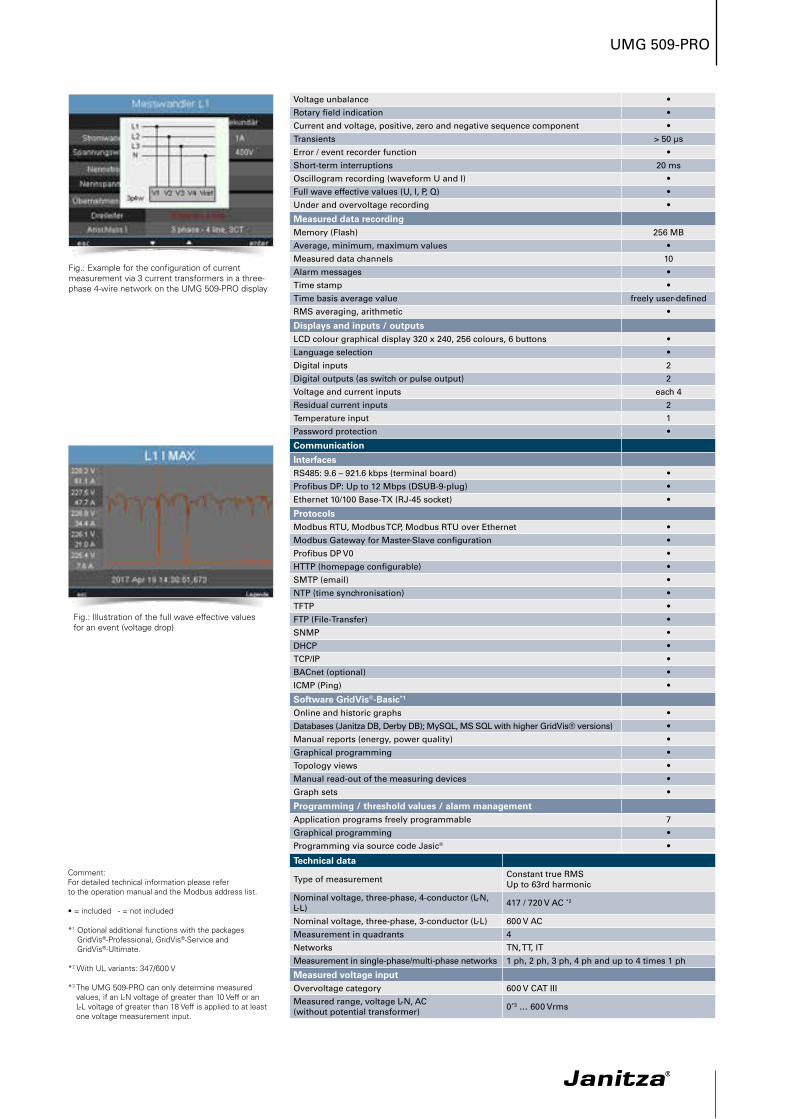
Fig.: Example for the configuration of current measurement via 3 current transformers in a three-phase 4-wire network on the UMG 509-PRO display
Voltage unbalance •Rotary field indication •Current and voltage, positive, zero and negative sequence component •Transients > 50 µsError / event recorder function •Short-term interruptions 20 msOscillogram recording (waveform U and I) •Full wave effective values (U, I, P, Q) •Under and overvoltage recording •
Measured data recordingMemory (Flash) 256 MBAverage, minimum, maximum values •Measured data channels 10Alarm messages •Time stamp •Time basis average value freely user-definedRMS averaging, arithmetic •
Displays and inputs / outputsLCD colour graphical display 320 x 240, 256 colours, 6 buttons •Language selection •Digital inputs 2Digital outputs (as switch or pulse output) 2Voltage and current inputs each 4Residual current inputs 2Temperature input 1Password protection •
CommunicationInterfacesRS485: 9.6 – 921.6 kbps (terminal board) •Profibus DP: Up to 12 Mbps (DSUB-9-plug) •Ethernet 10/100 Base-TX (RJ-45 socket) •
ProtocolsModbus RTU, Modbus TCP, Modbus RTU over Ethernet •Modbus Gateway for Master-Slave configuration •Profibus DP V0 •HTTP (homepage configurable) •SMTP (email) •NTP (time synchronisation) •TFTP •FTP (File-Transfer) •SNMP •DHCP •TCP/IP •BACnet (optional) •ICMP (Ping) •
Software GridVis®-Basic*1
Online and historic graphs •Databases (Janitza DB, Derby DB); MySQL, MS SQL with higher GridVis® versions) •Manual reports (energy, power quality) •Graphical programming •Topology views •Manual read-out of the measuring devices •Graph sets •
Programming / threshold values / alarm managementApplication programs freely programmable 7Graphical programming •Programming via source code Jasic® •
Technical data
Type of measurement Constant true RMS Up to 63rd harmonic
Nominal voltage, three-phase, 4-conductor (L-N, L-L) 417 / 720 V AC *2
Nominal voltage, three-phase, 3-conductor (L-L) 600 V ACMeasurement in quadrants 4Networks TN, TT, ITMeasurement in single-phase/multi-phase networks 1 ph, 2 ph, 3 ph, 4 ph and up to 4 times 1 ph
Measured voltage inputOvervoltage category 600 V CAT IIIMeasured range, voltage L-N, AC (without potential transformer) 0*3 … 600 Vrms
Comment: For detailed technical information please refer to the operation manual and the Modbus address list.
• = included - = not included
*1 Optional additional functions with the packages GridVis®-Professional, GridVis®-Service and GridVis®-Ultimate.
*2 With UL variants: 347/600 V
*3 The UMG 509-PRO can only determine measured values, if an L-N voltage of greater than 10 Veff or an L-L voltage of greater than 18 Veff is applied to at least one voltage measurement input.
UMG 509-PRO
Measured range, voltage L-L, AC (without potential transformer) 0*3 … 1000 Vrms
Resolution 0.01 VImpedance 4 MOhm / phaseFrequency measuring range 40 ... 70 HzPower consumption approx. 0.1 VASampling frequency 20 kHz / phase
Measured current inputRated current 1 / 5 AResolution 0.1 mAMeasurement range 0.005 … 7 AmpsOvervoltage category 300 V CAT IIIMeasurement surge voltage 4 kVPower consumption approx. 0.2 VA (Ri = 5 MOhm)Overload for 1 sec. 120 A (sinusoidal)Sampling frequency 20 kHz
Residual current / Temperature inputsResidual current inputs 2Measurement range, residual current inputs 0,05 ... 30 mATemperature input 1
Digital inputs and outputsNumber of digital inputs 2Maximum counting frequency 20 HzReaction time (Jasic® program) 200 msInput signal present 18 ... 28 V DC (typical 4 mA)Input signal not present 0 ... 5 V DC, current < 0.5 mANumber of digital outputs 2Switching voltage max. 60 V DC, 30 V ACSwitching current max. 50 mA Eff AC / DC Output of voltage dips 20 msPulse output (energy pulse) max. 20 HzMaximum cable length up to 30 m unscreened, from 30 m screened
Mechanical propertiesWeight 1080 gDevice dimensions in mm (H x W x D) 144 x 144 x approx. 81Battery Type CR2450, 3 V, Li-MnProtection class per EN 60529 Front: IP40; Rear: IP20Assembly per IEC EN 60999-1 / DIN EN 50022 Front panel installationConnecting phase (U / I), Single core, multi-core, fine-stranded Terminal pins, core end sheath
0.2 to 2.5 mm²0.2 to 2.5 mm²
Environmental conditionsTemperature range Operation: K55 (-10 ... +55 °C)Relative humidity Operation: 0 ... 75 % RHOperating height 0 ... 2,000 m above sea levelDegree of pollution 2Installation position user-defined
Electromagnetic compatibilityElectromagnetic compatibility of electrical equipment Directive 2004/108/EC
Electrical appliances for application within particular voltage limits Directive 2006/95/EC
Equipment safetySafety requirements for electrical equipment for measurement, regulation, control and laboratory use – Part 1: General requirements
IEC/EN 61010-1
Part 2-030: Particular requirements fortesting and measuring circuits IEC/EN 61010-2-030
Noise immunityClass A: Industrial environment IEC/EN 61326-1Electrostatic discharge IEC/EN 61000-4-2Voltage dips IEC/EN 61000-4-11
EmissionsClass B: Residential environment IEC/EN 61326-1Radio disturbanc voltage strength 30 – 1000 MHz IEC/CISPR11/EN 55011Radiated interference voltage 0.15 – 30 MHz IEC/CISPR11/EN 55011
SafetyEurope CE labellingUSA and Canada UL variants available
Firmware
Firmware update
Update via GridVis® software.Firmware download (free of charge) from the website:http://www.janitza.com
Comment: For detailed technical information please refer to the operation manual and the Modbus address list.
• = included - = not included
*3 The UMG 509-PRO can only determine measured values, if an L-N voltage of greater than 10 Veff or an L-L voltage of greater than 18 Veff is applied to at least one voltage measurement input.
K2
External auxilliary voltage
+
24V DC
-
K1
DC
DC
11
12
13
Digital Ouput 1
Digital Ouput 2
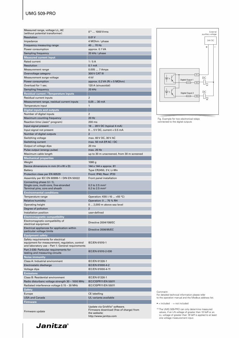
Fig. Example for two electronical relays connected to the digital outputs