sa1e - sys-tek
TRANSCRIPT
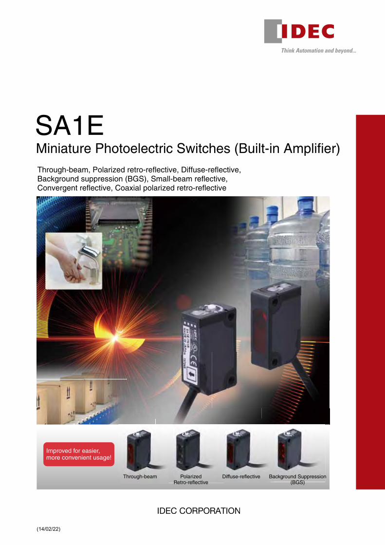
Through-beam PolarizedRetro-reflective
Diffuse-reflective Background Suppression(BGS)
Improved for easier,more convenient usage!
SA1E Miniature Photoelectric Switches (Built-in Amplifier)Through-beam, Polarized retro-reflective, Diffuse-reflective, Background suppression (BGS), Small-beam reflective, Convergent reflective, Coaxial polarized retro-reflective
(14/02/22)

2
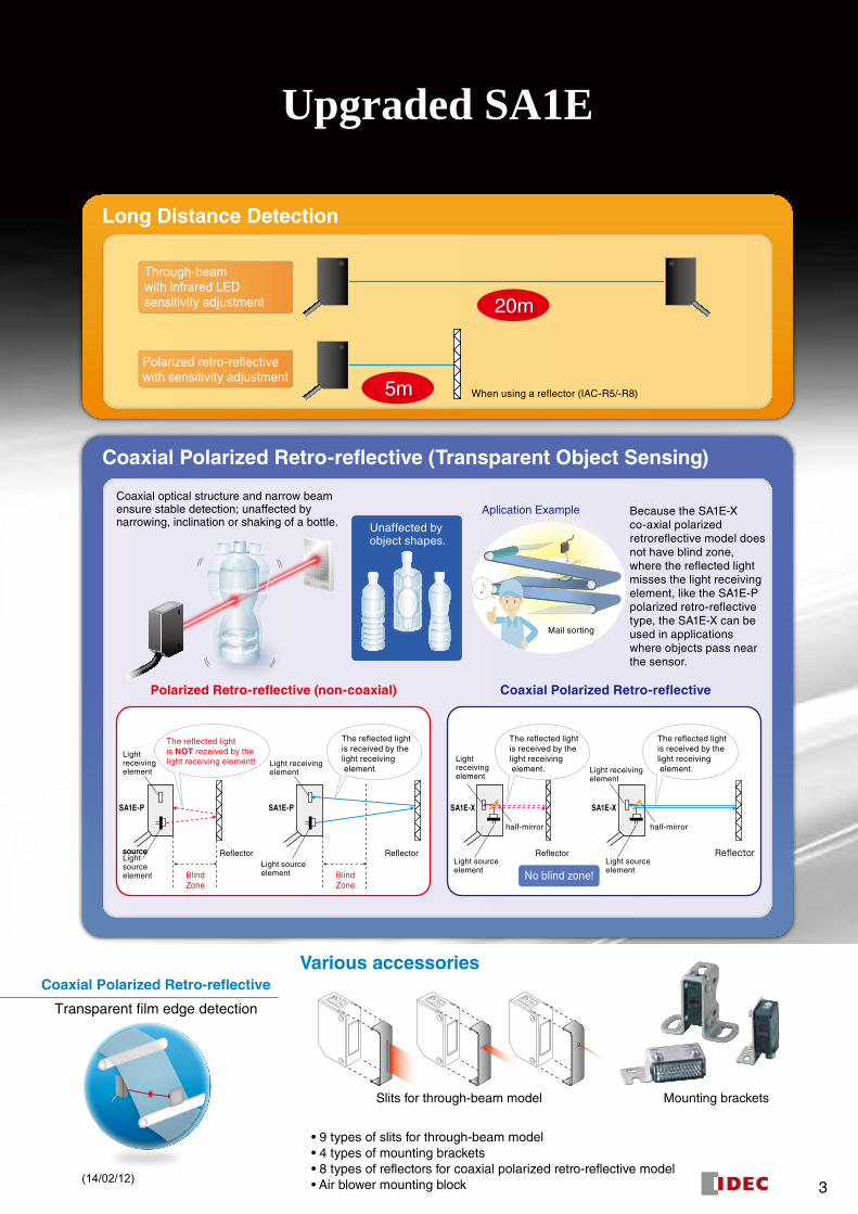
Upgraded SA1E
Various accessories
• 9 types of slits for through-beam model• 4 types of mounting brackets• 8 types of reflectors for coaxial polarized retro-reflective model• Air blower mounting block
SA1ESA1EIgnores the background and detects the objects only. Smaller beammakes it possible to detect small objects and narrow gaps between theobjects. The upgraded model is also less affected by the object colors.
Background Suppression(BGS)
Coaxial Polarized Retro-reflective (Transparent Object Sensing)
Long Distance Detection
Several SA1E models are protected from incorrect wiring:• Through-beam with infrared LED sensitivity adjustment• Polarized retro-reflective with sensitivity adjustment• Diffuse-reflective• Background Suppression (BGS)
The improved sensing ability detects objects of differentcolors such as black and white more accurately.
Output reverse-polarity protection circuit
Detects objects of different colors
Mai
n C
ircui
t
Load+V
OUT
OV
12 to 24V DC
100mA max.
Because the SA1E-X co-axial polarized retroreflective model does not have blind zone, where the reflected light misses the light receiving element, like the SA1E-P polarized retro-reflective type, the SA1E-X can be used in applications where objects pass near the sensor.
Diffuse-reflective Background Suppression (BGS) Background Suppression (BGS)
Through-beamwith infrared LEDsensitivity adjustment
Polarized retro-reflectivewith sensitivity adjustment
♪
Protected!
♪
When using a reflector (IAC-R5/-R8)
20m
5m
Object
Optical AxisSensing Point(machine axis)
Large beamsize
Conventional
Conventional
ON
Object
Smaller beamsize
Detects the objectcloser to the opticalaxis
Upgrade Model
Upgrade Model
Upgrade Model
ON- +
Unaffected by object shapes.
Background Suppression (BGS)
Slits for through-beam model Mounting brackets
♪
Mail sorting
ONON ONOFF
ONOFF ONON
Background Suppression (BGS) Coaxial Polarized Retro-reflective
Application Examples
Transparent film edge detectionMulti-story parking lot
Through-beam
Mirror-like objects
Polarized Retro-reflective
Automatic faucet
Diffuse-reflective
PCB line
Miniature Photoelectric Switches(Built-in Amplifier)
SA1E-P SA1E-XSA1E-P
Reflector
BlindZone
BlindZone
Lightreceivingelement
Lightreceivingelement
Lightsourceelement
Reflector
Light receivingelement
Light sourceelement
The reflected lightis NOT received by thelight receiving element!
The reflected lightis received by thelight receiving element.
Coaxial Polarized Retro-reflectivePolarized Retro-reflective (non-coaxial)
Reflector
No blind zone!
SA1E-X
ReflectorLight sourceelement
Light sourceelement
sourcesource
Light receivingelement
half-mirrorhalf-mirror
The reflected lightis received by thelight receiving element.
The reflected lightis received by thelight receiving element.
Aplication ExampleCoaxial optical structure and narrow beam ensure stable detection; unaffected by narrowing, inclination or shaking of a bottle.
(14/02/12)
3
Upgraded SA1E
Various accessories
• 9 types of slits for through-beam model• 4 types of mounting brackets• 8 types of reflectors for coaxial polarized retro-reflective model• Air blower mounting block
SA1ESA1EIgnores the background and detects the objects only. Smaller beammakes it possible to detect small objects and narrow gaps between theobjects. The upgraded model is also less affected by the object colors.
Background Suppression(BGS)
Coaxial Polarized Retro-reflective (Transparent Object Sensing)
Long Distance Detection
Several SA1E models are protected from incorrect wiring:• Through-beam with infrared LED sensitivity adjustment• Polarized retro-reflective with sensitivity adjustment• Diffuse-reflective• Background Suppression (BGS)
The improved sensing ability detects objects of differentcolors such as black and white more accurately.
Output reverse-polarity protection circuit
Detects objects of different colors
Mai
n C
ircui
t
Load+V
OUT
OV
12 to 24V DC
100mA max.
Because the SA1E-X co-axial polarized retroreflective model does not have blind zone, where the reflected light misses the light receiving element, like the SA1E-P polarized retro-reflective type, the SA1E-X can be used in applications where objects pass near the sensor.
Diffuse-reflective Background Suppression (BGS) Background Suppression (BGS)
Through-beamwith infrared LEDsensitivity adjustment
Polarized retro-reflectivewith sensitivity adjustment
♪
Protected!
♪
When using a reflector (IAC-R5/-R8)
20m
5m
Object
Optical AxisSensing Point(machine axis)
Large beamsize
Conventional
Conventional
ON
Object
Smaller beamsize
Detects the objectcloser to the opticalaxis
Upgrade Model
Upgrade Model
Upgrade Model
ON- +
Unaffected by object shapes.
Background Suppression (BGS)
Slits for through-beam model Mounting brackets
♪
Mail sorting
ONON ONOFF
ONOFF ONON
Background Suppression (BGS) Coaxial Polarized Retro-reflective
Application Examples
Transparent film edge detectionMulti-story parking lot
Through-beam
Mirror-like objects
Polarized Retro-reflective
Automatic faucet
Diffuse-reflective
PCB line
Miniature Photoelectric Switches(Built-in Amplifier)
SA1E-P SA1E-XSA1E-P
Reflector
BlindZone
BlindZone
Lightreceivingelement
Lightreceivingelement
Lightsourceelement
Reflector
Light receivingelement
Light sourceelement
The reflected lightis NOT received by thelight receiving element!
The reflected lightis received by thelight receiving element.
Coaxial Polarized Retro-reflectivePolarized Retro-reflective (non-coaxial)
Reflector
No blind zone!
SA1E-X
ReflectorLight sourceelement
Light sourceelement
sourcesource
Light receivingelement
half-mirrorhalf-mirror
The reflected lightis received by thelight receiving element.
The reflected lightis received by thelight receiving element.
Aplication ExampleCoaxial optical structure and narrow beam ensure stable detection; unaffected by narrowing, inclination or shaking of a bottle.
(14/02/12)

54
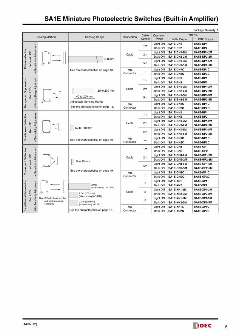
SA1E Miniature Photoelectric Switches (Built-in Amplifier)Simple, compact design for world-wide usage.•Seven sensing methods•Cable model (three cable lengths) and M8 connector models are
available.•NPN output, PNP output, light ON, dark ON can be selected.•Sensing range doubled with SA1E-T through-beam (infrared LED/
with sensitivity adjustment) and SA1E-P polarized retro-reflective models (with sensitivity adjustment).
•Highly stable with excellent resistance against vibration and shock resistance.
•Coaxial polarized retro-reflective model (SA1E-X) ensures stable detection, unaffected by construction, inclination or shaking of the object, and a high-speed response and small beam ensure reliable counting of target objects moving at high speed.
•Air blower mounting block for installing an air blower to clean the lens sur face. Ideal to maintain a clean lens surface and sensor perfor-mance.
•Nine types of slits for through-beam models available. •CE marked, UL listed.
Package Quantity: 1
Sensing Method Sensing Range Connection Cable Length
Operation Mode
Part No.
NPN Output PNP Output
Thr
ough
-bea
m
Infr
ared
LE
D
w/S
ensi
tivity
Adj
ustm
ent
20m
See the characteristics on page 15.
Cable
1mLight ON SA1E-TN1 SA1E-TP1
Dark ON SA1E-TN2 SA1E-TP2
2mLight ON SA1E-TN1-2M SA1E-TP1-2M
Dark ON SA1E-TN2-2M SA1E-TP2-2M
5mLight ON SA1E-TN1-5M SA1E-TP1-5M
Dark ON SA1E-TN2-5M SA1E-TP2-5M
M8 Connector —
Light ON SA1E-TN1C SA1E-TP1C
Dark ON SA1E-TN2C SA1E-TP2C
w/o
Sen
sitiv
ity A
djus
tmen
t
15m
See the characteristics on page 16.
Cable
1mLight ON SA1E-TN1-NA SA1E-TP1-NA
Dark ON SA1E-TN2-NA SA1E-TP2-NA
2mLight ON SA1E-TN1-NA-2M SA1E-TP1-NA-2M
Dark ON SA1E-TN2-NA-2M SA1E-TP2-NA-2M
5mLight ON SA1E-TN1-NA-5M SA1E-TP1-NA-5M
Dark ON SA1E-TN2-NA-5M SA1E-TP2-NA-5M
M8 Connector —
Light ON SA1E-TN1C-NA SA1E-TP1C-NA
Dark ON SA1E-TN2C-NA SA1E-TP2C-NA
Red
LE
D
w/S
ensi
tivity
Adj
ustm
ent
10m
See the characteristics on page 17.
Cable
1mLight ON SA1E-TAN1 SA1E-TAP1
Dark ON SA1E-TAN2 SA1E-TAP2
2mLight ON SA1E-TAN1-2M SA1E-TAP1-2M
Dark ON SA1E-TAN2-2M SA1E-TAP2-2M
5mLight ON SA1E-TAN1-5M SA1E-TAP1-5M
Dark ON SA1E-TAN2-5M SA1E-TAP2-5M
M8 Connector —
Light ON SA1E-TAN1C SA1E-TAP1C
Dark ON SA1E-TAN2C SA1E-TAP2C
Pol
ariz
ed R
etro
-ref
lect
ive
Red
LE
D w/S
ensi
tivity
Adj
ustm
ent 5.0m (50mm)
When using IAC-R5/R8
2.0m (150mm)When using IAC-RS2
3.0m (50mm)When using IAC-R6
1.3m (150mm)When using IAC-RS1
1.6m (100mm)When using IAC-R7
Cable
1mLight ON SA1E-PN1 SA1E-PP1
Dark ON SA1E-PN2 SA1E-PP2
2mLight ON SA1E-PN1-2M SA1E-PP1-2M
Dark ON SA1E-PN2-2M SA1E-PP2-2M
5mLight ON SA1E-PN1-5M SA1E-PP1-5M
Dark ON SA1E-PN2-5M SA1E-PP2-5M
M8 Connector —
Light ON SA1E-PN1C SA1E-PP1C
Dark ON SA1E-PN2C SA1E-PP2C
w/o
Sen
sitiv
ity A
djus
tmen
t
1.4m (150mm)When using IAC-RS2
2.0m (100mm)When using IAC-R6
1.1m (150mm)When using IAC-RS1
1.0m (100mm)When using IAC-R7
3.0m (100mm)When using IAC-R5/R8
Cable
1mLight ON SA1E-PN1-NA SA1E-PP1-NA
Dark ON SA1E-PN2-NA SA1E-PP2-NA
2mLight ON SA1E-PN1-NA-2M SA1E-PP1-NA-2M
Dark ON SA1E-PN2-NA-2M SA1E-PP2-NA-2M
5mLight ON SA1E-PN1-NA-5M SA1E-PP1-NA-5M
Dark ON SA1E-PN2-NA-5M SA1E-PP2-NA-5M
M8 Connector —
Light ON SA1E-PN1C-NA SA1E-PP1C-NA
Dark ON SA1E-PN2C-NA SA1E-PP2C-NA
C US
LISTED
Note: Maintain at least the distance shown in the ( ) between the SA1E photoelectric switch and reflector. Reflectors are not sup plied and must be ordered separately.
See characteristics on page 18.
(Note)
Cable Model
Connector Model
(14/02/12)
54
SA1E Miniature Photoelectric Switches (Built-in Amplifier)
Package Quantity: 1
Sensing Method Sensing Range Connection Cable Length
Operation Mode
Part No.
NPN Output PNP Output
Diff
use-
refle
ctiv
e
Infr
ared
LE
D
w/S
ensi
tivity
Adj
ustm
ent
Cable
1mLight ON SA1E-DN1 SA1E-DP1
Dark ON SA1E-DN2 SA1E-DP2
2mLight ON SA1E-DN1-2M SA1E-DP1-2M
Dark ON SA1E-DN2-2M SA1E-DP2-2M
5mLight ON SA1E-DN1-5M SA1E-DP1-5M
Dark ON SA1E-DN2-5M SA1E-DP2-5M
M8 Connector —
Light ON SA1E-DN1C SA1E-DP1C
Dark ON SA1E-DN2C SA1E-DP2C
Bac
kgro
und
Sup
pres
sion
Red
LE
D
w/S
ensi
ng R
ange
Adj
ustm
ent
Cable
1mLight ON SA1E-BN1 SA1E-BP1
Dark ON SA1E-BN2 SA1E-BP2
2mLight ON SA1E-BN1-2M SA1E-BP1-2M
Dark ON SA1E-BN2-2M SA1E-BP2-2M
5mLight ON SA1E-BN1-5M SA1E-BP1-5M
Dark ON SA1E-BN2-5M SA1E-BP2-5M
M8 Connector —
Light ON SA1E-BN1C SA1E-BP1C
Dark ON SA1E-BN2C SA1E-BP2C
Sm
all-b
eam
Ref
lect
ive
Red
LE
D
w/S
ensi
tivity
Adj
ustm
ent
Cable
1mLight ON SA1E-NN1 SA1E-NP1
Dark ON SA1E-NN2 SA1E-NP2
2mLight ON SA1E-NN1-2M SA1E-NP1-2M
Dark ON SA1E-NN2-2M SA1E-NP2-2M
5mLight ON SA1E-NN1-5M SA1E-NP1-5M
Dark ON SA1E-NN2-5M SA1E-NP2-5M
M8 Connector —
Light ON SA1E-NN1C SA1E-NP1C
Dark ON SA1E-NN2C SA1E-NP2C
Con
verg
ent R
efle
ctiv
e
Infr
ared
LE
D
w/S
ensi
tivity
Adj
ustm
ent
Cable
1mLight ON SA1E-GN1 SA1E-GP1
Dark ON SA1E-GN2 SA1E-GP2
2mLight ON SA1E-GN1-2M SA1E-GP1-2M
Dark ON SA1E-GN2-2M SA1E-GP2-2M
5mLight ON SA1E-GN1-5M SA1E-GP1-5M
Dark ON SA1E-GN2-5M SA1E-GP2-5M
M8 Connector —
Light ON SA1E-GN1C SA1E-GP1C
Dark ON SA1E-GN2C SA1E-GP2C
Coax
ial P
olar
ized
Retro
-refle
ctive
Red
LE
D
With
Sen
sitiv
ity A
djus
tmen
t
Note: Reflector is not supplied and must be ordered separately.
2.0m(when using IAC-R9)
1.0m [100 mm](when using IAC-R10)
1.0m [100 mm](when using IAC-R11)
See the characteristics on page 19.
Cable
1Light ON SA1E-XN1 SA1E-XP1
Dark ON SA1E-XN2 SA1E-XP2
2Light ON SA1E-XN1-2M SA1E-XP1-2M
Dark ON SA1E-XN2-2M SA1E-XP2-2M
5Light ON SA1E-XN1-5M SA1E-XP1-5M
Dark ON SA1E-XN2-5M SA1E-XP2-5M
M8 Connector —
Light ON SA1E-XN1C SA1E-XP1C
Dark ON SA1E-XN2C SA1E-XP2C
700 mm
See the characteristics on page 18.
20 to 200 mm
See the characteristics on page 18.
40 to 200 mm
Adjustable Sensing Range
50 to 150 mm
See the characteristics on page 19.
5 to 35 mm
See the characteristics on page 19.
(14/02/12)

76
SA1E Miniature Photoelectric Switches (Built-in Amplifier)
Slits (for through-beam)
Item Slit Size Part No. Ordering No. Package Quantity
Vertical Slit
0.5 mm × 18 mm SA9Z-S06 SA9Z-S06PN02
2
1.0 mm × 18 mm SA9Z-S07 SA9Z-S07PN02
2.0 mm × 18 mm SA9Z-S08 SA9Z-S08PN02
Horizontal Slit
0.5 mm × 6.5 mm SA9Z-S09 SA9Z-S09PN02
1.0 mm × 6.5 mm SA9Z-S10 SA9Z-S10PN02
2.0 mm × 6.5 mm SA9Z-S11 SA9Z-S11PN02
Round Slit
ø0.5 mm SA9Z-S12 SA9Z-S12PN02
ø1.0 mm SA9Z-S13 SA9Z-S13PN02
ø2.0 mm SA9Z-S14 SA9Z-S14PN02
Reflectors (for polarized retro-reflective)
Item Part No. Package Quantity
Reflector
Standard IAC-R5
1
Small IAC-R6
Large IAC-R8
Narrow (rear/side mounting) IAC-R7M
Narrow (rear mounting) IAC-R7B
Narrow (side mounting) IAC-R7S
Tape Type (40 × 35 mm) IAC-RS1
Tape Type (80 × 70 mm) IAC-RS2
ReflectorMounting Bracket
For IAC-R5 IAC-L2
For IAC-R6 IAC-L3
For IAC-R8 IAC-L5
•See page 13 for dimensions.•The IAC-L2 is not supplied with mounting screws and nuts. Use
commercially available M4 screws and nuts for mounting the IAC-R5 reflector.
•The IAC-L3 is supplied with two mounting screws (M3 × 8 mm sems screws).•The IAC-L5 is supplied with two mounting screws (M4 × 10 mm sems
screws).•The IAC-R7M and IAC-R7S are supplied with two M3 × 8 mm self-tapping
screws, two flat washers, and two spring washers.•The IAC-R7B is supplied with an M3 × 8 mm self-tapping screw, a flat
washer, and a spring washer.
Sensor Mounting Brackets
Item Part No. Package Quantity
Main Unit Mounting Brackets
Vertical Mounting SA9Z-K01
1Horizontal Mounting SA9Z-K02
Cover type SA9Z-K03
Back Mounting SA9Z-K04
•Two mounting screws (M3 × 12 mm sems screws) are supplied with the SA9Z-K01 and SA9Z-K02.
•Two mounting screws (M3 × 14 mm sems screws) are supplied with the SA9Z-K03.
•The through-beam model requires two mounting brackets, one each for the projec tor and the receiver.
•The SA9Z-K02 cannot be used for the connector models.•Contact IDEC about mounting brackets for the connector.
Connector Cable (for M8 connector model)
Number of Core Wires Style & Length Part No. Package
Quantity
4
Straight, 2m SA9Z-CM8K-4S2
1Right angle, 2m SA9Z-CM8K-4L2
Straight, 5m SA9Z-CM8K-4S5
Right angle, 5m SA9Z-CM8K-4L5
Reflectors (used only for coaxial polarized retro-reflective)
Item Part No. Package Quantity
Reflector
Standard IAC-R9
1Small IAC-R10
Ultra-small IAC-R11
Reflector Mounting Bracket For IAC-R9 IAC-L3
Air Blower Mounting BlockItem Part No. Package Quantity
Air Blower Mounting Block SA9Z–A02 1
•Two mounting screws (M3 × 20 mm sems screws), one M5 × 6 mm screw for plugging the air supply port, and one gasket (0.5 mm thick) are supplied.
•The air tube fitting and mounting bracket are not supplied and must be ordered separately (recommended mounting bracket: SA9Z-K01).
•Material: Anodized aluminum surface
Sensitivity Control ScrewdriverItem Part No. Package Quantity
Sensitivity Control ScrewdriverSA9Z-AD01 1
Accessories (optional)
(14/02/12)

76
SA1E Miniature Photoelectric Switches (Built-in Amplifier)
Specifications
Sensing Method
Through-beam Polarized Retro-reflective
Infrared LEDWith sensitivity
adjustment
Red LEDWith sensitivity
adjustment
Infrared LEDWithout sensitivity
adjustment
With sensitivity adjustment
Without sensitivity adjustment
Part No. SA1E-T SA1E-TA SA1E-T -NA SA1E-P SA1E-P -NA
Power Voltage 12 to 24V DC (Operating range: 10 to 30V DC) equipped with reverse-polarity protection
Current Draw Projector: 15 mAReceiver: 20 mA 30 mA
Sensing Range 20m 10m 15m
5.0m (IAC-R5/R8)3.0m (IAC-R6)2.0m (IAC-RS2) 1.3m (IAC-RS1)1.6m (IAC-R7) (Note 1)
3.0m (IAC-R5/R8)2.0m (IAC-R6)1.4m (IAC-RS2) 1.1m (IAC-RS1)1.0m (IAC-R7) (Note 2)
Adjustable Sensing Range —
Detectable Object Opaque Opaque, transparent and mirror-like objects
Hysteresis —
Response Time 1 ms maximum
Sensitivity Adjustment Adjustable using a potentiometer (approx. 240°)Through-beam and polarized retro-reflective models are also available without sensitivity adjustment.
Sensing Range Adjustment —
Light Source Element Infrared LED Red LED Infrared LED Red LED
Operation Mode Light ON/Dark ON
Control Output
NPN open collector or PNP open collector (30V DC, 100 mA maximum, short-circuit protection)
Voltage drop: 2V max. (30V DC, 100 mA max)1.2V max. (30V DC, 10 mA max)With output reverse connection protection control circuit
Voltage drop: 1.2V max.
Voltage drop: 2V max. (30V DC, 100 mA max)1.2V max. (30V DC, 10 mA max)With output reverse connection protection control circuit
Voltage drop: 1.2V max.
LED IndicatorsOperation LED: YellowStable LED: GreenPower LED: Green (Through-beam model projector)
Interference Prevention — Two units can be mounted in close proximity.
Degree of Protection IP67 (IEC 60529)
Extraneous Light Immunity Sunlight: 10,000 lux maximum, Incandescent lamp: 5,000 lux maximum (at receiver)
Operating Temperature –25 to +55°C (no freezing)
Operating Humidity 35 to 85% RH (no condensation)
Storage Temperature –40 to +70°C (no freezing)
Insulation Resistance Between live part and mounting bracket: 20 MΩ maximum (500V DC megger)
Dielectric Strength Between live part and mounting bracket: 1000V AC, 50/60 Hz, 1 minute
Vibration ResistanceDamage limits: 10 to 500 90 Hz, 1 cycle 5 mins, in each of 3 axes
Damage limits: 10 to 55 Hz, double amplitude 0.75 mm, 20 cycles in each of 3 axes
Damage limits: 10 to 500 90 Hz, 1 cycle 5 mins, in each of 3 axes
Damage limits: 10 to 55 Hz, double amplitude 1.5 mm, 20 cycles in each of 3 axes
Shock ResistanceDamage limits: 1000 m/s2, 6 shocks in each of 3 axes Damage limits: 500 m/s2, 10 shocks in each of 3 axes Damage limits: 1000 m/s2,
6 shocks in each of 3 axesDamage limits: 500 m/s2, 10 shocks in each of 3 axes
Material
Case PC/PBT
Lens PMMA PC PMMA
Indicator Model PC
Weight (approx.)
Cable Model Projector: 30g , Receiver: 30g (Note 3)
Connector Model Projector: 10g, Receiver: 10g
Connection Method
Cable Model ø3.5 mm, 3-core, 0.2 mm2 cable (2-core for the projector of through-beam model)
Connector Model M8 connector (4-pin)
Note 1: Maintain at least the distance shown below between the SA1E photoelectric switch and reflector. IAC-R5/R6/R8: 50 mm
IAC-R7: 100 mm IAC-RS1/RS2: 150 mm
The detection distance cannot be guaranteed if the reflector is deformed or the tape type reflector is applied on uneven surface.Note 2: Maintain at least the distance shown below between the SA1E photoelectric switch and reflector.
IAC-R5/R6/R7/R8: 100 mm IAC-RS1/RS2: 150 mm
Note 3: Cable length: 1m (50g when the cable length is 2m. 110g when the cable length is 5m.)
(14/02/12)

98
SA1E Miniature Photoelectric Switches (Built-in Amplifier)
SpecificationsSensing Method Diffuse-reflective Background Suppression
(BGS) Small-beam Reflective Convergent Reflective Coaxial Polarized Retro-reflective
Part No. SA1E-D SA1E-B SA1E-N SA1E-G SA1E-X
Power Voltage 12 to 24V DC (Operating range: 10 to 30V DC), equipped with reverse-polarity protection
Current Draw 30 mA 20 mA
Sensing Range700 mm(using 200 × 200 mm white mat paper)
20 mm to preset (using 200 × 200 mm white mat paper)
50 to 150 mm(using 100 × 100 mm white mat paper)
5 to 35 mm(using 100 × 100 mm white mat paper)
2 m(using IAC-R9)
Adjustable Sensing Range — 40 to 200 mm —
Detectable Object Opaque/Transparent Opaque Opaque/Transparent Opaque, transparent and mirror-like objects
Hysteresis 20% maximum 10% maximum 20% maximum —
Response Time 1 ms maximum 500 μs maximum
Sensitivity AdjustmentAdjustable using a potentiometer (approx. 240°)
— Adjustable using a potentiometer (approx. 240°)
Sensing Range Adjustment — 6-turn control knob —
Light Source Element Infrared LED Red LED Infrared LED Red LED
Operation Mode Light ON/Dark ON
Control Output
NPN open collector or PNP open collector (30V DC, 100 mA maximum with short circuit protection circuit)
Voltage drop: 2V max. (30V DC, 100 mA)1.2V max. (30V DC, 100 mA)Output reverse-polarity protection circuit
Voltage drop: 2V max. (30V DC, 100 mA)Output reverse-polarity protection circuit
Voltage drop: 1.2V max.
LED Indicators Operation LED: YellowStable LED: Green Operation LED: Yellow Operation LED: Yellow
Stable LED: Green Operation LED: Yellow
Interference Prevention Two units can be mounted in close proximity.
Degree of Protection IP67 (IEC 60529)
Extraneous Light Immunity Sunlight: 10,000 lux maximum, Incandescent lamp: 5,000 lux maximum (at receiver)
Operating Temperature –25 to +55°C (no freezing)
Operating Humidity 35 to 85% RH (no condensation)
Storage Temperature –40 to +70°C (no freezing)
Insulation Resistance Between live part and mounting bracket: 20 MΩ maximum (500V DC megger)
Dielectric Strength Between live part and mounting bracket: 1000V AC, 50/60 Hz, 1 minute
Vibration Resistance Damage limits: 10 to 500 Hz, 1 cycle 5 mins in each of 3 axes Damage limits: 10 to 55 Hz, double amplituide 1.5mm, 20 cycles in each of 3 axes
Shock Resistance Damage limits: 1000 m/s2, 6 shocks in each of 3 axes Damage limits: 500 m/s2, 10 shocks in each of 3 axes
Material
Housing PC/PBT
Lens PMMA PC PMMA
Indicator cover PC
Weight (approx.)
Cable Model 30g (Note 1) 35g (Note 2) 30g (Note 1)
Connector Model 10g 25g 10g
Connection Method
Cable Model ø3.5 mm, 3-core, 0.2 mm2 cable
Connector Model M8 connector (4-pin)
Note 1: Cable length: 1m (50g when the cable length is 2m. 110g when the cable length is 5m.)Note 2: Cable length: 1m (55g when the cable length is 2m. 120g when the cable length is 5m.)
(14/02/12)

98
SA1E Miniature Photoelectric Switches (Built-in Amplifier)
+V
OUT
0V
Brown (1)
Black (4)
Load
12V to24V DC
Blue (3)Mai
n C
ircui
t
+VBrown (1)
Load
Black (4)OUT
12V to24V DC
0VBlue (3)M
ain
Circ
uit
+VBrown (1)
Black (4)Load
OUT 12V to24V DC
0VBlue (3)M
ain
Circ
uit
+VBrown (1)
LoadBlack (4)
OUT12V to
24V DC
0VBlue (3)M
ain
Circ
uit
PNP OutputNPN Output
PNP OutputNPN Output
Through-beam Projector
Through-beam Projector
+VBrown (1)
12V to24V DC
0VBlue (3)
Mai
n C
ircui
t
+VBrown (1)
12V to24V DC
0VBlue (3)
Mai
n C
ircui
t
Connector Pin Assignment
➀ (OUT)
➁ (NC)
➂ (0V)
➃ (+V)
Connector Pin Assignment
➀ (OUT)
➁ (NC)
➂ (0V)
➃ (+V)
Connector Pin Assignment
➀ (OUT)
➁ (NC)
➂ (0V)
➃ (+V)
Connector Pin Assignment
➀ (OUT)
➁ (NC)
➂ (0V)
➃ (+V)
➃ (NC)
➁ (NC)
➂ (0V)
➀ (+V)
Connector Pin Assignment
➃ (NC)
➁ (NC)
➂ (0V)
➀ (+V)
Connector Pin Assignment
Through-beam (infrared/red LED without sensitivity adjustment)Polarized reflective (without sensitivity adjustment)Small-beam reflectiveConvergent reflectiveCoaxial polarized retro-reflective
Slit and Sensing RangeA slit, which changes the beam size of through-beam sensors, can easily be attached to the sensing side of the through-beam projector and receiver. Three different slit widths are available.
Slit
w/Sensitivity Adjustment w/o Sensitivity Adjustment
Sensing Range (m)Minimum Detectable Object Width (mm)
(Note 1)Sensing Range (m)
Minimum Detectable Object Width (mm)
(Note 2)
Attached on: Attached on:
Part No. Slit Width: A (see page 14) Receiver Receiver/
Projector Receiver Receiver/Projector Receiver Receiver/
Projector Receiver Receiver/Projector
SA9Z-S06 0.5 mm 2.5 1.0 0.5 0.5 5.0 1.5 7.0 0.5
SA9Z-S07 1.0 mm 3.5 1.5 1.0 1.0 7.0 3.0 7.0 1.0
SA9Z-S08 2.0 mm 6.0 3.5 2.0 2.0 9.0 5.5 7.0 2.0
SA9Z-S09 0.5 mm 2.0 0.7 0.5 0.5 4.0 1.5 7.0 0.5
SA9Z-S10 1.0 mm 3.0 1.5 1.0 1.0 7.0 2.5 7.0 0.8
SA9Z-S11 2.0 mm 5.5 3.0 2.0 2.0 9.0 5.0 7.0 1.5
SA9Z-S12 0.5 mm 0.8 0.08 0.5 0.5 1.3 0.1 5.0 0.5
SA9Z-S13 1.0 mm 1.5 0.3 1.0 1.0 2.5 0.3 5.0 0.6
SA9Z-S14 2.0 mm 2.5 1.2 2.0 2.0 5.5 1.6 5.0 1.7
Note 1: At 1mm from receiver surface.Note 2: At the intermediate point of maximum sensing range between the projector and receiver.•Theslitcanbeinstalledontothefronteasily(seethefigureatright).
Slit(stainless steel)
The slit can be pressed tosnap onto the front easily.
Horizontal slits and round slits have an orientation. Make sure that the TOP marking comes on top of the sensor (LED side).
Output Circuit & Wiring DiagramThrough-beam (infrared LED w/sensitivity adjustment)Polarized reflective (w/sensitivity adjustment)Diffuse-reflectiveBackground suppression
(14/02/12)

1110
SA1E Miniature Photoelectric Switches (Built-in Amplifier)
2.9
19.4
6.7
6.4
0.9
19.5
2-M3
25.4
31.5
10.83.4
7.5
11.0
(Note 6)
(注3)(Note 3)
2−M3
Receiver/Projector
ø3.5
ø3.5
3.419.5
1.2
25.4
31.5
6.510.8
17.4
13.49.0
2.9
10.8
17.4
10.86.5
4.0
17.1
7.1
12.7
8.8
(Note
5)
Operation LED(yellow)
Sensing RangeControl (6 turns)
Stable LED (green) (Note 2)Sensitivity Control(Note 2) (Note 4)
Receiver
Projector
Receiver
Projector
Operation LED (yellow)(Note 1)
17.1 19
.87.8
Projector/Receiver
10.8
31.5
ø3.5
19.5
25.4
3.4
7.2
9.9
7.8
19.8
1.2
8.2
11.7
3.2 Operation LED (yellow)
2-M3
Stable LED(green) (Note 6)
Sensitivity Control
Projector
Receiver
17.2
4.5
ø5.2
14.5
11.0
2.9
10.8
0.9
31.5
25.4
2-M3
Projector/Receiver(coaxial)
19.5
3.4
ø3.5
DimensionsCable Model
Through-beam (infrared LED w/sensitivity adjustment)
Through-beam (infrared LED without/sensitivity adjustment)(red LED with sensitivity adjustment)
Coaxial polarized retro-reflective
Through-beam
Through-beam
Polarized retro-reflectiveDiffuse-reflectiveBackground Suppression (BGS)
Polarized retro-reflectiveSmall-beam reflectiveConvergent reflective
Polarized retro-reflective (with sensitivity adjustment)Diffuse-reflectiveBackground Suppression (BGS)
Polarized retro-reflective (without sensitivity adjustment)Small-beam reflectiveConvergent reflective
(14/02/12)

1110
SA1E Miniature Photoelectric Switches (Built-in Amplifier)
2-M3
M8×1
6.3
10.8
2.9
9.0
13.4
31.5
25.4
1.2
4.5
19.53.4
17.1
4.0
6.510.8
17.4
12.7
7.1
17.4
10.86.5
8.8
(Note 7)
M8×12-M3
19.53.4
2.9
11.07.5
31.5
25.4
0.9
4.5
6.2
10.86.4
6.7
19.4
(Note 7)
10.8
8.2
11.7
3.2
安定表示灯(緑)(注6)
感度調整ボリューム
動作表示灯(黄)
(Note 6)
(注3)(Note 3)
Receiver/Projector
Operation LED(yellow)
Sensing RangeControl (6 turns)
Stable LED (green) (Note 2)Sensitivity Control(Note 2) (Note 4)
Receiver
Projector
Receiver
Projector
Operation LED (yellow)(Note 1)
DimensionsConnector Model
Through-beam (infrared LED w/senistivity adjustment)
Through-beam (infrared LED without sensitivity adjustment)(red LED with sensitivity adjustment)
Coaxial polarized retro-reflective
Polarized retro-reflective (with sensitivity adjustment)Diffuse-reflectiveBackground Suppression (BGS)
Polarized retro-reflective (without sensitivity adjustment)Small-beam reflectiveConvergent reflective
10.8
31.5
4.5
6.3
19.5
25.4
3.4
7.2
9.9
7.8
19.8
1.2
8.2
11.7
3.2
2-M3
17.1
7.8
19.8
Projector/Receiver
Operation LED(yellow)
Stable LED(green) (Note 6)
Sensitivity Control
Projector
Receiver
M8×1
Through-beam Polarized retro-reflectiveDiffuse-reflectiveBackground Suppression (BGS)
Through-beam Polarized retro-reflectiveSmall-beam reflectiveConvergent reflective
17.2
4.5
0.9
31.5
25.4
10.8
2.9 11.0
14.5
M8
4.5
(Not
e 7)
6.3
2-M3
19.5
3.4
ø5.2Projector/Receiver(coaxial)
Note 1: Power ON LED (green) for through-beam projectorNote 2: No sensitivity control and stable LED are attached on the through-beam projector.Note 3: 5.2 mm for polarized retro-reflective modelNote 4: No sensitivity control is installed on the type without sensitivity adjustment.Note 5: Cable length depends on model.Note 6: Stable LED is not provided on the background suppression model.Note 7: The connector length is 18 mm when a right-angle connector cable
(SA9Z-CM8K-4L∗) is attached.
(with right angle connector)
(with right angle connector)
(14/02/12)

1312
SA1E Miniature Photoelectric Switches (Built-in Amplifier)
46
2.5
18
R9.5
253.
2
13
3.2
25
6
ø55ø39
19 29
7
20º
40º
5.5
5.5
ø25
6.2
19
7º14º4
2-R
25
10.813.0
7.2 17
.112
.325
.4
3.2
9.3
31.5
(5.3
)1.
215.0
0.6
(Note 1)(Note 2)
19.529.0(3.2)
ø39
.0ø
55.0
13.010.8
25.4
12.7
12.3
17.1
(18)(55)
(18)(55)
46
2.5
18
R9.5
253.
2
13
3.2
25
6
ø55ø39
19 29
7
20º
40º
5.5
5.5
ø25
6.2
19
7º14º4
2-R
25
10.813.0
7.2 17
.112
.325
.4
3.2
9.3
31.5
(5.3
)1.
215.0
0.6
(Note 1)(Note 2)
19.529.0(3.2)
ø39
.0ø
55.0
13.010.8
25.4
12.7
12.3
17.1
(18)(55)
(18)(55)
1.2
42.5
21.5
7゚13.7
14゚
3.4
3.4
14.0
3.2
12.3
25.4
8.0
9.0 3.04.5
12.3
17.1 25
.442
.5
7.2
9.9
25.0
(Note 1)
(Note 2)
(Note 1)(Note 2)
9.3
31.5
1.2
13.7
0.5 19.5
13.4
6.0
24.8
21.5
10.8
25.0
25.4
12.7
12.3
42.5
17.1
(3.2)1.
2
42.5
21.5
7゚13.7
14゚
3.4
3.4
14.0
3.2
12.3
25.4
8.0
9.0 3.04.5
12.3
17.1 25
.442
.5
7.2
9.9
25.0
(Note 1)
(Note 2)
(Note 1)(Note 2)
9.3
31.5
1.2
13.7
0.5 19.5
13.4
6.0
24.8
21.5
10.8
25.0
25.4
12.7
12.3
42.5
17.1
(3.2)
Dimensions
Mounting Brackets
Vertical Mounting SA9Z-K01
Horizontal Mounting SA9Z-K02
Cover Type SA9Z-K03
Back Mounting SA9Z-K04
With Mounting Bracket
With Mounting Bracket
With Mounting Bracket
With Mounting Bracket
10.8
24.813.4
28.419.51.6
15.3
25.4
21.512.7
1.2
14.6
8.4
34.8
55.0
10.6
14º
4.5
12.0 5.0
4.5
ø3.4
6.0
17.6
15.3
25.4
12.3
31.5
1.2
12.721.5
1.0 19.5
1.28.014.6 (3.2)
10.6
34.8
55.0
7.2
17.1
28.0
1.28.0
14.6 (3.2)
28.0
12.7
17.1
34.8
55.0
10.6
(Note 1)
(Note 1)
(Note 2)
(Note 2)
15.3
25.4
21.512.7
1.2
14.6
8.4
34.8
55.0
10.6
14º
4.5
12.0 5.0
4.5
ø3.4
6.0
17.6
15.3
25.4
12.3
31.5
1.2
12.721.5
1.0 19.5
1.28.014.6 (3.2)
10.6
34.8
55.0
7.2
17.1
28.0
1.28.014.6 (3.2)
28.0
12.7
17.1
34.8
55.0
10.6
(Note 1)
(Note 1)
(Note 2)
(Note 2)
Material: stainless steel
Material: stainless steel
Material: stainless steel
148
3.4
3025
5 7t=1.2
32
77
24 25.4
3.2
Material: Stainless Steel
Note 1: Center of optical axis (through-beam)Note 2: Center of optical axis (polarized retro-reflective,
diffuse reflective, small-beam reflective, and convergent reflective model)
(Note 1)
(Note 1)
(Note 2)
(Note 2)
(14/02/12)

1312
SA1E Miniature Photoelectric Switches (Built-in Amplifier)
Reflectors
3.3
(Effective re�ecting area: 30 × 31)
2-ø3.6
8.335.3
34.3
42.3
8
25
4(2
1)
35
40
Thickness = 0.5 mm
61
(Effective re�ecting area: 47 × 47)
2-ø4.53040
30.4
51.2
51.2
8
IAC-R5 IAC-R6
2-M3 tappingscrew hole(ø2.6 mm,depth 8.6 mm)
Positioning Projection(ø3.0 mm, height 1.0 mm)
11.5
2-7.
3
3.0
12.4
25.4
12.4
33.3
M3 tapping screw hole(ø2.6 mm, depth 7.7 mm)
12.4
2-7.
3
Positioning Projection(ø3.0 mm, height 1.0 mm)
M3 tapping screw hole(ø2.6 mm, depth 7.7 mm)
11.5
12.4
33.3
2-M3 tappingscrew hole(ø2.6 mm,depth 8.6 mm)
25.4
12.4
2-7.
33.0
12.4
33.3
All dimensions in mm.
IAC-RS1IAC-R870
80
Thickness = 0.5 mm
(Effective re�ecting area: 47.2 × 47.2)
2-ø4.3
51
72 60
39
•Effective reflecting area: 8.6 × 29.5 •The mounting plate for reflector must be 0.8 to 2.5 mm in thickness.
IAC-R7M (rear/side mounting) IAC-R7B (rear mounting) IAC-R7S (side mounting)
IAC-RS2
6.13.5
4.4
61.6 5
15
51.640202-R2.2 2-R2.2
(Reflecting surface 47×47.6)
3.16.1
19.4
60 50
2-ø4.4 2-ø7
(Reflecting surface 38.5×16)
23.2
2632
20.2
2-ø3.8
(Reflecting surface 18×18.2)
IAC-R9 IAC-R10 IAC-R11
(14/02/12)
1514
SA1E Miniature Photoelectric Switches (Built-in Amplifier)
ø5.2
28
ø9.6 16.5
➃ Black ➁ White
➂ Blue ➀ Brown
Cable length:2 or 5m
Dimensions
Material: SPCC (zinc chromate plating, black)
42
5.5
19
6
28
3774
113
2
2-ø3.4
4-ø4.4
30
58
70
60
44
20
1.6
25
1610
86
Material: SPCC (zinc plating)
8-M3 × 0.5 holes
254.5
11
10
35
(3)
404.5
10
Material: SPCC (zinc plating)
26
1235
(28)
(3) 20
(2)
61
1615
187
4050
11
8-M3 × 0.7 holes
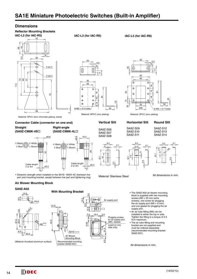
IAC-L2 (for IAC-R5) IAC-L3 (for IAC-R6) IAC-L5 (for IAC-R8)
Reflector Mounting Brackets
Connector Cable (connector on one end)
Straight(SA9Z-CM8K-4S
Right-angle(SA9Z-CM8K-4L
ø5.2
ø9.6
32
➃ Black ➁ White
➂ Blue ➀ Brown
Cable length:2 or 5m
•Dielectric strength when installed on the SA1E: 1000V AC (between live part and mounting bracket, except between live part and tightening ring)
Air Blower Mounting Block
SA9Z-A02
5.8
14.0
8.0
37.0
25.4
25.06.9
M5 P0.8
M5P0.8 42.5
14.0
6.5
31.5
8.0
3.4
10.9
(3.8
)
2.03.5 19.5Plugging screwsfor air supply port(M5), Gasket(used on oneside only)
Air supply port
Air BlowerMounting Block
SA1E-∗∗∗∗
(3.2)
Recommended mountingbracket (SA9Z-K01)
2-ø3
.2
(Material: Anodized aluminum surface)
With Mounting Bracket •The SA9Z-A02 air blower mounting block is supplied with two mounting screws (M3 × 20 mm sems screws), one screw for plugging the air supply port (M5 × 6 mm), and one gasket for plugging the air supply port.
•An air tube fitting (M5) can be installed to either the top or side. Tighten the fitting to a torque of 0.5 N·m maxi mum.
•The air tube fitting and mounting bracket are not supplied and must be ordered separately (recommended mounting bracket: SA9Z-K01).
All dimensions in mm.
Vertical Slit Horizontal Slit Round Slit
SA9Z-S06SA9Z-S07SA9Z-S08
SA9Z-S09SA9Z-S10SA9Z-S11
SA9Z-S12SA9Z-S13SA9Z-S14
18
8.2
32.1
A 6.1
0.3
A
8.2
32.1
6.1
0.3
4.4
6.5øA4.
4
8.2
32.1
6.1
0.3
Material: Stainless Steel All dimensions in mm.
(14/02/12)
1514
SA1E Miniature Photoelectric Switches (Built-in Amplifier)
Characteristics (Typical)1-1. Through-beam SA1E-T (Infrared LED w/sensitivity adjustment)
Excess Gain (Without slit) Lateral Displacement (Without slit) Angle (Without slit)
Excess Gain (With vertical slit) Excess Gain (With horizontal slit) Excess Gain (With round slit)
Lateral Displacement (With 0.5-mm vertical slit) Lateral Displacement (With 1.0-mm vertical slit) Lateral Displacement (With 2.0-mm vertical slit)
Lateral Displacement (With 0.5-mm horizontal slit) Lateral Displacement (With 1.0-mm horizontal slit) Lateral Displacement (With 2.0-mm horizontal slit)
Lateral Displacement (With ø0.5-mm round slit) Lateral Displacement (With ø1.0-mm round slit) Lateral Displacement (With ø2.0-mm round slit)
10
1
100
0 5 10 15 20 25 30
Sensing Distance (m)
Exc
ess
Gai
n
OperationLevel
Sensing Distance X (m)La
tera
l Dis
plac
emen
t Y (
mm
)
0
-800
-400
400
200
-200
-600
600
800
0 5 10 15 20 25 30
X
Y
-90
-60
-30
0
30
60
90
0 5 10 15 20
θ
X
Sensing Distance X (m)
Rec
eive
r Ang
le θ
(°)
Exc
ess
Gai
n
Sensing Distance (m)
1
10
100
0 1 2 3 4 5 6 7 1098
2.0 mmslits onboth sides
1.0 mmslits onboth sides
0.5 mmslits onboth sidesOperation
Level
Sensing Distance (m)
Exc
ess
Gai
n
1
10
100
0 1 2 3 4 5 6 7 1098
1.0 mmslits onboth sides
2.0 mmslits onboth sides
0.5 mmslits onboth sidesOperation
Level
Exc
ess
Gai
n
1
10
100
0 1.0 2.0 5.03.0 4.0
ø0.5mmslits onboth sides ø1.0mm
slits onboth sides
ø2.0mmslits onboth sides
Sensing Distance (m)
OperationLevel
Sensing Distance X (m)
Late
ral D
ispl
acem
ent Y
(m
m)
-250-200-150-100-50
50100150200250
0 1 2 3 4 5 76
0
Y
X
Slits onboth sides
One slit onreceiver
Sensing Distance X (m)
Late
ral D
ispl
acem
ent Y
(m
m)
-300
-200
-100
0
100
200
300
0 2 4 6 108
Y
X
One slit onreceiver
Slits onboth sides
Late
ral D
ispl
acem
ent Y
(m
m)
0
-400
-300
-200
-100
100
200
300
400
0 2 4 6 8 10 12
Y
X
Slits onboth sides
One slit onreceiver
Sensing Distance X (m)
Late
ral D
ispl
acem
ent Y
(m
m)
Sensing Distance X (m)
-250
-150-200
-100-50
050
150200
100
250
0 1 2 3 4 765
Y
X
One slit onreceiver
Slits onboth sides
Late
ral D
ispl
acem
ent Y
(m
m)
Sensing Distance X (m)
-250-200-150-100-50
050
100150200250
0 1 2 3 4 5 6 10987
Y
X
One slit onreceiver
Slits onboth sides
Late
ral D
ispl
acem
ent Y
(m
m)
-400
-300
-200-100
0100
200
300
400
0 2 4 6 8 1210
Y
X
Slits onboth sides
One slit onreceiver
Sensing Distance X (m)
Late
ral D
ispl
acem
ent Y
(m
m)
Sensing Distance X (m)
-50-40-30-20-10
01020304050
0 0.4 0.8 1.2 2.01.6
Y
X
One slit onreceiver
Slits onboth sides
Late
ral D
ispl
acem
ent Y
(m
m)
Sensing Distance X (m)
-100-80-60-40-20
0204060
10080
0 0.5 1.0 1.5 2.0 2.5 3.0 3.5 4.0
Y
X
One slit onreceiver
Slits onboth sides
Late
ral D
ispl
acem
ent Y
(m
m)
Sensing Distance X (m)
0
-160
-80-120
-40
80
40
120
160
0 1 2 3 4 5 6
Y
X
One slit onreceiver
Slits onboth sides
(14/02/12)

1716
SA1E Miniature Photoelectric Switches (Built-in Amplifier)
Characteristics (Typical)1-2. Through-beam SA1E-T-NA (Infrared LED w/o sensitivity adjustment)
Excess Gain (Without slit) Lateral Displacement (Without slit) Angle (Without slit)
Excess Gain (With vertical slit) Excess Gain (With horizontal slit) Excess Gain (With round slit)
Lateral Displacement (With 0.5-mm vertical slit) Lateral Displacement (With 1.0-mm vertical slit) Lateral Displacement (With 2.0-mm vertical slit)
Lateral Displacement (With 0.5-mm horizontal slit) Lateral Displacement (With 1.0-mm horizontal slit) Lateral Displacement (With 2.0-mm horizontal slit)
Lateral Displacement (With ø0.5-mm round slit) Lateral Displacement (With ø1.0-mm round slit) Lateral Displacement (With ø2.0-mm round slit)
100
10
10 5 10 15 20 25 30
Sensing Distance (m)
Exc
ess
Gai
n
OperationLevel
1000800600400200
0-200-400-600-800
-1000 0 5 10 15 20X
Y
Sensing Distance X (m)
Late
ral D
ispl
acem
ent Y
(m
m)
-80
-40
-60
-20
020
40
8060
0 5 10 15 20XX
θ
Sensing Distance X (m)
Rec
eive
r Ang
le θ
(°)
100
10
10 2 4 6 8 10 12
1.0 mmslits onboth sides
0.5 mmslits onboth sides
2.0 mmslits onboth sides
Sensing Distance (m)
Exc
ess
Gai
n
OperationLevel
0 2 4 6 8 10 12
100
10
1
1.0 mmslits onboth sides
0.5 mmslits onboth sides
2.0 mmslits onboth sides
Sensing Distance (m)
Exc
ess
Gai
n
OperationLevel
0 0.5 1.0 1.5 2.0 2.5 3.0
100
10
1
ø1.0 mmslits onboth sides
ø0.5 mmslits onboth sides
ø2.0 mmslits onboth sides
Sensing Distance (m)
Exc
ess
Gai
n
OperationLevel
250200150100
500
2 4 6 8 10
-50-100-150-200-250 0
Slits onboth sides
One sliton receiver
X
Y
Sensing Distance X (m)
Late
ral D
ispl
acem
ent Y
(m
m) 300
200
100
0
-100
-200
-300 0 5 10 15
One sliton receiver
Slit onboth sides
X
Y
Sensing Distance X (m)
Late
ral D
ispl
acem
ent Y
(m
m) 500
400300200100
0-100-200-300-400-500 5 10 15 200
One sliton receiverSlit on
both sides
X
Y
Sensing Distance X (m)
Late
ral D
ispl
acem
ent Y
(m
m)
200
150
100
50
0
-50
-100
-150
-200 0 2 4 6 8 10
One sliton receiver
Slits onboth sides
X
Y
Sensing Distance X (m)
Late
ral D
ispl
acem
ent Y
(m
m) 400
300
200
100
0-100
-200
-300
-400 0 2 4 6 8 10
One sliton receiver
Slits onboth sides
X
Y
Sensing Distance X (m)
Late
ral D
ispl
acem
ent Y
(m
m) 400
300
200
100
0-100
-200
-300
-400 5 10 15 200
One sliton receiver
Slits onboth sides
XY
Sensing Distance X (m)
Late
ral D
ispl
acem
ent Y
(m
m)
0
-20
-40
-60
20
40
60
0 0.5 1.0 1.5 2.0 2.5 3.0
One sliton receiver
Slits onboth sides
X
Y
Sensing Distance X (m)
Late
ral D
ispl
acem
ent Y
(m
m)
0-50
-100
-150
-200
50
100
150
200
0 1 2 3 4 5 6
One sliton receiver
Slits onboth sides
X
Y
Sensing Distance X (m)
Late
ral D
ispl
acem
ent Y
(m
m)
0
-50
-100
-150
-200
50
100
150
200
0 1 2 3 4 5 6
One sliton receiver
Slits onboth sides
X
Y
Sensing Distance X (m)
Late
ral D
ispl
acem
ent Y
(m
m)
(14/02/12)

1716
SA1E Miniature Photoelectric Switches (Built-in Amplifier)
Characteristics (Typical)1-3. Through-beam SA1E-TA (Red LED w/sensitivity adjustment)
Excess Gain (Without slit) Lateral Displacement (Without slit) Angle (Without slit)
Excess Gain (With vertical slit) Excess Gain (With horizontal slit) Excess Gain (With round slit)
Lateral Displacement (With 0.5-mm vertical slit) Lateral Displacement (With 1.0-mm vertical slit) Lateral Displacement (With 2.0-mm vertical slit)
Lateral Displacement (With 0.5-mm horizontal slit) Lateral Displacement (With 1.0-mm horizontal slit) Lateral Displacement (With 2.0-mm horizontal slit)
Lateral Displacement (With ø0.5-mm round slit) Lateral Displacement (With ø1.0-mm round slit) Lateral Displacement (With ø2.0-mm round slit)
0 5 10
10
1
100
15 20Sensing Distance (m)
Exc
ess
Gai
n
OperationLevel
Sensing Distance X (m)La
tera
l Dis
plac
emen
t Y (
mm
)
-600
-400
-200
0
200
400
600
0 5 10 15 20
X
Y
-60
-40
-20
0
20
40
60
0
XX
θ
Sensing Distance X (m)
Rec
eive
r Ang
le θ
(°)
Exc
ess
Gai
n
Sensing Distance (m)
1
10
100
0 1 2 3 4 5 6 7 8
1.0 mmslits onboth sides
2.0 mmslits onboth sides0.5 mm
slits onboth sides
OperationLevel
Sensing Distance (m)
Exc
ess
Gai
n
1
10
100
0 1 2 3 4 5 6 7
2.0 mmslits onboth sides
1.0 mmslits onboth sides
0.5 mmslits onboth sides
OperationLevel
Exc
ess
Gai
n
1
10
100
0 0.5 1.0 1.5 2.0 2.5 3.0
ø2.0mmslits onboth sides
ø0.5mmslits onboth sides
ø1.0mmslits onboth sides
Sensing Distance (m)
OperationLevel
Sensing Distance X (m)
Late
ral D
ispl
acem
ent Y
(m
m)
-20010 2 3 4 5 6
-150
-100
-50
50
0
100
150
200
XX
YY
Slits onboth sides
One slit onreceiver
Sensing Distance X (m)
Late
ral D
ispl
acem
ent Y
(m
m)
-250-200-150-100-50
050
100150200250
0 2 4 6 8XX
YY
One slit onreceiver
Slits onboth sides
Sensing Distance X (m)
Late
ral D
ispl
acem
ent Y
(m
m)
-400-300
-200-100
0
100200300
400
0 2 4 6 8 10 12XX
YY
One slit onreceiver
Slits onboth sides
Late
ral D
ispl
acem
ent Y
(m
m)
Sensing Distance X (m)
-150
-100
-50
0
50
100
150
0 1 2 3 4 5
X
Y
One slit onreceiver
Slits onboth sides
Late
ral D
ispl
acem
ent Y
(m
m)
Sensing Distance X (m)
-200-150
-100-50
050
100150
200
0 1 2 3 4 5 6 7
X
Y
One slit onreceiver
Slits onboth sides
Late
ral D
ispl
acem
ent Y
(m
m)
Sensing Distance X (m)
-250-200-150-100-50
050
100150200250
0 2 4 6 8 10
X
Y
One slit onreceiver
Slits onboth sides
Late
ral D
ispl
acem
ent Y
(m
m)
Sensing Distance X (m)
-50-40-30-20-10
01020304050
0 0.2 0.4 0.6 0.8 1.0 1.2 1.4 1.6
X
Y
One slit onreceiver
Slits onboth sides
Late
ral D
ispl
acem
ent Y
(m
m)
Sensing Distance X (m)
-80-60
-40-20
020
4060
80
0 0.5 1.0 1.5 2.0 2.5 3.0 3.5
X
Y
One slit onreceiver
Slits onboth sides
Late
ral D
ispl
acem
ent Y
(m
m)
Sensing Distance X (m)
-150
-100
-50
0
50
100
150
0 1 2 3 4 5 6
X
Y
One slit onreceiver
Slits onboth sides
(14/02/12)
1918
SA1E Miniature Photoelectric Switches (Built-in Amplifier)
Characteristics (Typical)2-1. Polarized Retro-reflective SA1E-P (Red LED w/sensitivity adjustment)Excess Gain Lateral Displacement Angle (when using IAC-R5/-R8)
2-2. Polarized Retroreflective SA1E-P-NA (Red LED w/o sensitivity adjustment)Excess Gain Lateral Displacement Angle (when using IAC-R5/-R8)
3. Diffuse-Reflective SA1E-D (Infrared LED w/sensitivity adjustment)Excess Gain Lateral Displacement Angle (when using IAC-R5/-R8)
4. Background Suppression SA1E-B (Red LED w/sensitivity adjustment)Lateral Displacement (Preset 100 mm) Lateral Displacement (Preset 200 mm) Light Beam Diameter
Sensing Distance vs. Hysteresis Control Knob vs. Sensing Distance Color Matte Paper and Other Materials
Sensing Distance (m)
Exc
ess
Gai
n
OperationLevel
IAC-R5/8
IAC-R6IAC-RS2
IAC-R7
IAC-RS1
100
10
10 1 2 3 5 874 6
Sensing Distance X (m)La
tera
l Dis
plac
emen
t Y (
mm
)
80
120
40
0
-40
-80
-120
1 2 3 4 85 6 70
IAC-RS1
IAC-RS2
IAC-R7IAC-R6
IAC-R5/8
X
Y
Sensing Distance X (m)
Ref
lect
or A
ngle
θ (
°)
0 1 2 3 5 6 7 84-80-60
-40
-20
2040
80
60
0
IAC-RS1IAC-RS2
IAC-R5/8IAC-R7 IAC-R6
X
θ
Sensing Distance (m)
Exc
ess
Gai
n
OperationLevel
1 2 3 4 50
100
10
1
IAC-R5/8IAC-RS1 IAC-RS2
IAC-R7∗ IAC-R6
Sensing Distance X (m)
Late
ral D
ispl
acem
ent Y
(m
m)
1 2 3 4 50
80
60
40
20
0
-20
-40
-60
-80
X
Y
IAC-RS1IAC-RS2
IAC-R7∗IAC-R6
IAC-R5/8
Sensing Distance X (m)
Ref
lect
or A
ngle
θ (
°)
-60
-40
-20
20
40
60
0
XX
θ
IAC-R6 IAC-R5/8
1 2 3 4 50
IAC-RS1IAC-R7∗ IAC-RS2
Sensing Distance (m)
Exc
ess
Gai
n
OperationLevel
1
10
100
0 300 600 900 1200 1500Sensing Distance X (m)
Late
ral D
ispl
acem
ent Y
(m
m)
-100-80-60-40-20
020406080
100
0 200 400 600 800 12001000 1400
Object: 200 × 200 mmwhite mat paperX
Y
Side Length A (mm)
Sen
sing
Dis
tanc
e X
(m
m)
0
200
400
600
800
1000
1200
1400
0 40 80 120 160 200
X
A
Object: � A mmwhite mat paper
-10
-6-8
-2-4
02468
10
0 4020 60 80 100
X
Y
WhitePaper
BlackPaper
Object: 200 × 200 mmmat paperDistance setting:using white paper
Sensing Distance X (mm)
Late
ral D
ispl
acem
ent Y
(m
m)
-10
-4-6-8
-202468
10
0 40 80 120 160 200
X
YObject: 200 × 200 mmmat paperDistance setting:using white paper
BlackPaper
WhitePaper
Sensing Distance X (mm)
Late
ral D
ispl
acem
ent Y
(m
m)
Sensing Distance (mm)
Ligh
t Bea
m D
iam
eter
(m
m)
02468
1012141618
0 50 100 150 200 250
GrayPaper
6.0
1.0
0.0
2.0
3.0
4.0
5.0
0 50 100 150 200 250
BlackPaper
WhitePaper
Hys
tere
sis
(%)
Sensing Distance (mm)
1000
200300400500600700800900
1000
60 1 2 3 4 5
WhitePaper
GrayPaper
BlackPaper
Sen
sing
Dis
tanc
e (m
m)
Control Knob (turns)Comparison of sensing distance when set to detect white mat paper (200 x 200 mm) at 100 mm
Comparison of sensing distance when set to detect white mat paper (200 x 200 mm) at 200 mm
200160
80120
400
200160
80120
400
Bla
ck
Car
db
oard
Alu
min
um
Sta
inle
ss S
teel
Bra
ss
Ven
eer
Boa
rd
Whi
te
Red
Gre
en
Blu
e
Gra
y
Bla
ck
Car
db
oard
Alu
min
um
Sta
inle
ss S
teel
Bra
ss
Ven
eer
Boa
rd
Whi
te
Red
Gre
en
Blu
e
Gra
y
Dis
tanc
e (m
m)
Dis
tanc
e (m
m)
(14/02/12)

1918
SA1E Miniature Photoelectric Switches (Built-in Amplifier)
5. Small-beam Reflective SA1E-N (Red LED w/sensitivity adjustment)Excess Gain Lateral Displacement Object Size vs Sensing Distance
6. Convergent Reflective SA1E-G (Infrared LED w/sensitivity adjustment)
Excess Gain Lateral Displacement Object Size vs. Sensing Distance
Brightness vs. Sensing Distance
Object: Colour chips of colour standards according to JIS Z8721 (Non Glossy Edition)
Color Matte Paper and Other Materials
•The graph on the left shows the sensing distances for different colors and materials and can be used as a reference when setting the distance. Because sensing distance depends on the object’s size and surface condition, provide a sufficient distance.
•Note that sensing may be affected by reflective object behind the sensing object.
•Referring to the graph on the left, provide a suffi-cient distance between the photoelectric switch and background.
7. Coaxial Polarized Retro-reflective SA1E-X (Infrared LED w/sensitivity adjustment)Excess Gain
Exc
ess
Gai
n
100.0
10.0
1.0IAC-R10
0 0.5 1 1.5 2 2.5 3 3.5 4
IAC-R11 IAC-R9
Sensing Distance X (mm)
Lateral Displacement
Late
rl D
ispl
acem
ent Y
(mm
)
30
20
10
0
-10
-20
-300 0.5 1 1.5 2 2.5 3 3.5 4
IAC-R10
IAC-R11
IAC-R9
X
Y
Distance (mm)
Angle
Ref
lect
or A
ngle
θ (°
)
40
30
20
10
0
-10
-20
-30
-400 0.5 1 1.5 2 2.5 3 3.5 4
X
θ
IAC-R10 IAC-R11
IAC-R9
Sensing Distance X (mm)
Light Beam Diameter
40
35
30
25
20
15
10
5
00 0.2 0.4 0.6 0.8 1 1.2 1.4 1.6 1.8 2
Distance (m)
Ligh
t B
eam
Dia
met
er (m
m)
1
10
100
0 50 100 150 200 250Sensing Distance (mm)
Exc
ess
Gai
n
OperationLevel -15
-10
-5
0
5
10
15
0 50 100 150 200 250
XXY
Object: 100 × 100 mmwhite mat paper
Sensing Distance X (mm)
Late
ral D
ispl
acem
ent Y
(m
m)
0
50
100
150
200
250
300
0 20 40 60 80 100
XXA
Object: c A mmwhite mat paper
Side Length A (mm)
Sen
sing
Dis
tanc
e X
(m
m)
Distance (mm)
Exc
ess
Gai
n
OperationLevel 10 20 30 40 500
100
10
1
Sensing Distance X (mm)
Late
ral D
ispl
acem
ent Y
(m
m)
0 10 20 30 40 50
0
-2
-4
-6
-8
2
4
6
8
XX
Y Object: 100mmwhite mat paper
Side Length A (mm)
Sen
sing
Dis
tanc
e X
(m
m)
20 40 60 800
10
20
30
40
50
0
XXA
Object: � A mmwhite mat paper
Brightness
0
50
N2 N3 N9N4 N5 N6 N7 N8
2025
15105
30354045
Sen
sing
Dis
tanc
e X
(m
m)
Sen
sing
Dis
tanc
e (m
m)
0
10
20
30
40
50
60
70
80
90
100
Whi
te
Gre
en
Red
Blu
e
Gra
y
Bla
ck
Car
db
oard
Alu
min
um
Sta
inle
ss S
teel
Mirr
or
Gal
vani
zed
Stee
l
Bla
ck R
ubbe
r
PC
Boa
rd (b
lack
)
PC
Boa
rd (g
reen
)
Object Size: 50 mm
(14/02/12)

2120
SA1E Miniature Photoelectric Switches (Built-in Amplifier)
1. Indicator and Output Operation (except for background suppression model)
•The operation LED turns on (yellow) when the control output is on. Operation LED (yellow)
Stable LED (green)Sensitivity Control
•The stable LED turns on (green) either at stable incident or stable interruption. Make sure to use the photoelectric switch after the stable operation is ensured.
•In the light ON operation, the output turns on when the receiv-ing light intensity level is 1.0 or over as shown on the right.
•In the dark-ON operation, the output turns on when the receiv-ing light intensity level is 1.0 or less as shown on the right.
Receiving Light Intensity Level
Light Receiving
Status
Stable LED
(green)
Operation LED (yellow)/Control Output
Light ON Dark ON
Operation Level
1.2 and over
Stable Incident ON
ON OFF
1.0
Unstable Incident
OFFUnstable
InterruptionOFF ON
0.8 and below
Stable Interruption ON
2. Optical Axis Alignment (Light ON)
Through-beamFasten the receiver temporarily. Place the projector to face the receiver. Move the projector up, down, right and left to find the range where the operation LED turns on. Fasten the projector in the middle of the range. Next, move the receiver up, down, right and left in the same manner and fasten in the middle of the range where the operation LED turns on. Make sure that stable LED turns on at stable incident and stable interruption.
Polarized retro-reflectiveInstall the reflector perpendicularly to the optical axis. Move the SA1E photoelectric switch up, down, right and left to find the range where the operation LED turns on. Fasten the switch in the middle of the range. Polarized retro-reflective model can be installed also by finding the position where the reflection of projected red light is most intense, while observing the reflection on the reflector from behind the switch. Make sure that stable LED turns on at stable incident and stable interruption.
Diffuse-reflective/Small-beam reflective/ Convergent reflectivePlace the SA1E photoelectric switch where the switch can detect the object. Move the switch up, down, right and left to find the range where the operation LED tuns on. Fasten the switch in the middle of the range. Make sure that stable LED turns on at stable incident and stable interruption. Because the light source element of small-beam reflective model is a red LED, visual inspection is possible as well.
3. Sensitivity AdjustmentReferring to the table at right, adjust the sensitivity of the SA1E photoelectric switch when necessary, in such cases as the through-beam model is used to detect small or translucent objects or the reflective model is affected by background. The table explains the status of operation LED when the operation mode is set to light ON.•After adjusting the sensitivity, make sure that stable LED turns
on at stable incident and stable interruption. For detecting ob-jects too small to turn on the stable LED, use an optional slit.
•Sensitivity is set to the maximum (+) at the factory before ship-ment. When adjusting the sensitivity, use the screwdriver sup-plied with the SA1E photoelectric switch to turn the control as shown below, to a torque of 0.05 N·m maximum.
Step Photoelectric Switch Status
Sensitivity Control Adjusting Procedure
1
Receiving light•Through-beam,
polarized reflective: No object detected
•Diffuse reflective, small-beam reflec-tive, convergent reflective: Object detected
Turn the control counter-clockwise to the mini mum (–). Then turn clock wise (toward +) until the operation LED turns on (turns off with dark ON type) (point A).
2
Light is interrupted•Through-beam,
polarized reflective: Object detected
•Diffuse reflective, small-beam reflec-tive, convergent reflective: No object detected
B
A
At interruption status, turn the control clock wise (toward +) from point A, until the operation LED turns on (turns off with dark ON type) (point B).If the operation LED does not turn on (turn off with dark ON type) even though the control has reached the maxi mum (+), set the maximum position (+) as point B.
3 —
C
B
A
Set the middle point between point A and B as point C.
4. Adjustment of Sensing Range for Background Sup pression (BGS) Model
•When adjusting the sensing range, follow the instruction below.
Step Distance Control Adjusting Procedure
1
Install the photoelectric switch and the object firmly. Turn the control counterclockwise until the operation LED turns off (turns on with dark ON type). From this point, turn the con trol clockwise until the operation LED turns on (turns off with dark ON type) (point A).
2
Remove the object, and confirm that the operation LED turns off (turns on with dark ON type). Turn the control clockwise until the operation LED turns on (detecting the back ground) (turns off with dark ON type) (point B). (Note 1)
3 Set the middle point between point A and B as point C. (Note 2)
Note 1: When the background is far off and not detected, turn the control 360°, and set the point as point C.
Note 2: Because the control is multi-turn, it may take more than one turn to move from point A to point B.
Note 3: Turning the control clockwise lengthens the sensing dis-tance.
Note 4: Background suppression (BGS) model is not provided with a stable LED.
Operation LED (yellow)
(Note 3)Sensing Range Control(6-turn)
(Note 4)
A
A
A
B
A
BC
Instructions
(14/02/12)

2120
SA1E Miniature Photoelectric Switches (Built-in Amplifier)
5. Power Supply and Wiring•Do not use the SA1E photoelectric switch at the transient sta-
tus immediately after turning on the power (approx. 100 ms, back ground suppression model: 200 ms). When the load and switch use different power supplies, make sure to power up the switch first.
•Use a power supply with little noise and inrush current, and use the photoelectric switch within the rated voltage range. Make sure that ripple factor is within the allowable limit. Do not apply AC volt age, otherwise the switch may blow out or burn.
•When using a switching power supply, make sure to ground the FG (frame ground) terminal, otherwise high-frequency noise may affect the photoelectric switch.
•Turn power off before inserting/removing the connector on photo electric switch. Make sure that excessive mechanical force is not applied to the connector. Connect the connector cable to a tight ening torque of 0.5 N·m maximum.
•To ensure the degree of protection, use the applicable con-nector cable for the connector model. Connector cables are ordered sepa rately.
•Avoid parallel wiring with high-voltage or power lines in the same conduit, otherwise noise may cause malfunction and damage. When wiring is long, use a separate conduit for wiring.
•Use a cable of 0.3 mm2 minimum core wires, then the cable can be extended up to 100m.
6. InstallationInstalling the Photoelectric Switch•Do not install the SA1E photoelectric switches in an area where
the switches are subject to the following conditions, otherwise mal function and damage may be caused.
∗ Inductive devices or heat source∗ Extreme vibration or shock∗ Large amount of dust∗ Toxic gases∗ Water, oil, chemicals∗ Outdoor
•Make sure to prevent sunlight, fluorescent light, and especially the fluorescent light of inverters from entering the receiver of the pho toelectric switch directly. Keep the through-beam model receiver away from intense extraneous light.
•Interference prevention allows two SA1E switches to be mount-ed in close proximity. However, the through-beam model is not equipped with interference prevention. Maintain appropriate dis tance between the switches referring to the lateral displace-ment characteristics.
•Because the SA1E photoelectric switches are IP67 waterproof, the SA1E can be exposed to water. However, wipe water drops and smears from the lens and slit using a soft cloth to make sure of the best detecting performance.
•Polycarbonate or acrylic resins are used for optical elements. Do not use ammonia or caustic soda for cleaning, otherwise optical elements will be dissolved. To remove dust and moisture build-up, use soft dry cloth.
•Tighten the mounting screws (M3) to a torque of 0.5 N·m. Do not tighten the mounting screws excessively or hit the switch with a hammer, otherwise the protection degree cannot be maintained.
Installing the Reflector•Use M4 mounting screws for the IAC-R5 and IAC-R8 reflector,
and M3 mount ing screws for the IAC-R6 reflector. Tighten the mounting screws to a tightening torque of 0.5 N·m maximum. Mounting screws are not supplied with the switch.
•Use the M3 self-tapping screw, flat washer, and spring washer to tighten the IAC-R7 reflector to a torque of 0.5 to 0.6 N·m.
•Optional reflector mounting bracket IAC-L2 is not supplied with mounting screws or nuts.
•IAC-L3 and IAC-L5 are supplied with mounting screws for mounting the reflector on the bracket.
•Reflector IAC-RS1 and IAC-RS2 can be installed directly on a flat surface using the adhesive tape attached to the back of the reflec tor. Before attaching the reflector, clean the board surface to ensure secure attachment.
Installing the air blower mounting block SA9Z-A02•When installing the SA9Z-A02 on the SA1E photoelectric
switch, use the attached M3 × 20 mounting screws and tighten to a torque of 0.5 N·m maximum.
•Do not use the mounting screw (M3 × 12) supplied with the mount ing bracket (SA9Z-K01) to mount the SA1E photoelectric switches.
•The SA9Z-A02 cannot be used with the through-beam slits (SA9Z-S06 to S14).
•The air tube fitting (M5) can be installed to either the top or side. The air tube is not supplied.
•Close the unused port using the air supply port plugging screw and gasket (supplied with SA1E) to a tightening torque of 1 to 2 N·m maximum. The recommended air pressure is 0.1 to 0.3 MPa.
Installing the background suppression (BGS) model•This sensor can detect objects correctly when the sensor head
is installed perpendicular to the moving object. Install the sen-sor head as shown below to minimize sensing errors.
Correct
Object Object Object
Correct Incorrect
•If the sensor is used in a place subject to a large variations in the ambient temperature, the characteristics may change de-pending on the target object. Be sure to check the operation under the actual operating conditions.
(14/02/12)
SA1E-L Miniature Laser Photoelectric Switches (Built-in Amplifier)
Through-beamPolarized Retro-reflective
Background Suppression (BGS)
Visible red laser, easy-to-align optical axis, fast response speed, and high precision sensing.
IP67
IP67 structure can be used in environments exposed to dust or water vapor.
Dust and water resistant
Positioning made easyBecause the optical axis can be positioned quickly, the photoelectric switch can be installed on a machine or system easily, even in applications requiring a long sensing range or detection of small objects.
EasyInstallation
RedLaser Because the visible red laser is easy to see in
both short (20 mm) and long (30 m) distances, the detecting position and optical axis can be found quickly. The small beam can detect small objects, and it also enables easy positioning of the sensor in applications where the beam has to pass through narrow spaces.All models are Class 1 laser compliant (JIS, IEC, FDA).
Small red laser beam
Fast250 µs
Detects fast-moving objectsThe 250 µs response speed is the fastest in its class. Closely-spaced objects on a fast-moving conveyor can be detected reliably.IDEC’s Unique Optical Lens Mechanism
Parallel beam to the housing axis makes installation of the photoelectric switch easy.
Housing
Beam is parallelto the housing axis
Optical Lens(positioned to make the beam parallel to the housing axis)
Optical Lens(fixed in the housing)
Laser Diode(fixed in the housing)
Top View
3 detection methods, 24 models
Model
Through-beam
SA1E-LT
Polarized Retroreflective
SA1E-LP
Background Suppression (BGS)
SA1E-LBDetectable Object Opaque Opaque Opaque
Sensing Range 30 m 0.3 to 10 m 20 to 300 mm
Response Time 25 0μs 250 μs 250 μs
NPN Output 4 types 4 types 4 types
PNP Output 4 types 4 types 4 types
IDEC CORPORATION (USA)1175 Elko Drive, Sunnyvale, CA 94089-2209, USATel: +1-408-747-0550 / (800) 262-IDEC (4332) Fax: +1-408-744-9055 / (800) 635-6246E-mail: [email protected]
IDEC CANADA LIMITED3155 Pepper Mill Court, Unit 4Mississauga, Ontario, L5L 4X7, CanadaTel: +1-905-890-8561, Toll Free: (800) 262-IDEC (4332) Fax: +1-905-890-8562E-mail: [email protected]
IDEC AUSTRALIA PTY. LTD.Unit 17, 104 Ferntree Gully Road,Oakleigh, Victoria 3166, AustraliaTel: +61-3-8523-5900, Toll Free: 1800-68-4332Fax: +61-3-8523-5999E-mail: [email protected]
IDEC ELECTRONICS LIMITEDUnit 2, Beechwood, Chineham Business Park, Basingstoke, Hampshire RG24 8WA, UKTel: +44-1256-321000, Fax: +44-1256-327755E-mail: [email protected]
6-64, Nishi-Miyahara 2-Chome, Yodogawa-ku, Osaka 532-0004, JapanTel: +81-6-6398-2527, Fax: +81-6-6398-2547E-mail: [email protected]
Speci�cations and other descriptions in this brochure are subject to change without notice.
Cat. No. EP1491-0 FEBRUARY 2014 PDF
IDEC ELEKTROTECHNIK GmbHWendenstrasse 331, 20537 Hamburg, GermanyTel: +49-40-25 30 54 - 0, Fax: +49-40-25 30 54 - 24E-mail: [email protected]
IDEC (SHANGHAI) CORPORATIONRoom 701-702 Chong Hing Finance Center, No. 288 Nanjing Road West, Shanghai 200003, PRCTel: +86-21-6135-1515 Fax: +86-21-6135-6225 / +86-21-6135-6226E-mail: [email protected]
IDEC (BEIJING) CORPORATIONRoom 211B, Tower B, The Grand Paci�c Building, 8A Guanghua Road, Chaoyang District, Beijing 100026, PRCTel: +86-10-6581-6131, Fax: +86-10-6581-5119
IDEC (SHENZHEN) CORPORATIONUnit AB-3B2, Tian Xiang Building, Tian’an Cyber Park, Fu Tian District, Shenzhen, Guang Dong 518040, PRCTel: +86-755-8356-2977, Fax: +86-755-8356-2944
IDEC IZUMI (H.K.) CO., LTD.Unit G & H, 26/F., MG Tower,No. 133 Hoi Bun Road, Kwun Tong, Kowloon, Hong Kong Tel: +852-2803-8989, Fax: +852-2565-0171E-mail: [email protected]
IDEC TAIWAN CORPORATION8F-1, No. 79, Hsin Tai Wu Road, Sec. 1, Hsi-Chih District, 22101 New Taipei City, Taiwan Tel: +886-2-2698-3929, Fax: +886-2-2698-3931E-mail: [email protected]
IDEC IZUMI ASIA PTE. LTD.No. 31, Tannery Lane #05-01,HB Centre 2, Singapore 347788Tel: +65-6746-1155, Fax: +65-6844-5995E-mail: [email protected]
IDEC ASIA (THAILAND) CO.,LTD.20th Fl., Sorachai Bldg., No.23/78,Soi Sukhumvit 63, Sukhumvit Rd.,Klongton-nua, Wattana, Bangkok 10110Tel: +662-392-9765, Fax: +662-392-9768E-mail: [email protected]
(14/02/12)