s7-softplc plc-416 plc-315 - controlmart · 2011-09-22 · s7-softplc plc-416 plc-315 manual...
TRANSCRIPT

S7-SoftPLC PLC-416 PLC-315
Manual Version 4.x

Page 2 SoftPLC IBHsoftec
S7 for Windows SoftPLC
Information in this document is subject to change without notice and does not represent a commitment on the part of IBH softec GmbH. The software and/or databases, described in this document, are furnished under a license agreement or non-disclosure agreement. The software and/or databases may be used or copied only in accordance with the terms of the agreement. It is against the law to copy the software on any medium except as specifically allowed in the license or non-disclosure agreement. The purchaser may make one copy of the software for backup purposes. No part of this manual and/or databases may be reproduced or transmitted in any form or by any means, (electronic or mechanical, including photocopying, recording, or information storage and retrieval systems), for any purpose other than the purchaser's personal use, without the express written permission of IBH softec GmbH.
© Copyright 1993 - 2007 IBHsoftec GmbH. All rights reserved.
Gesellschaft für Automatisierungstechnik mbH Turmstraße 77 D - 64743 Beerfelden / Odw. Germany Fon +49 60 68 / 30 01 Fax +49 60 68 / 30 74 Internet: www.IBHsoftec.de E-Mail: [email protected] Simatic, Step5, Step7, MicroWin, Graph5, S7-200, S7-300, S7-400 and MPI are registered trademarks of Siemens AG, Berlin and Munich. Windows, ActiveX are registered trademarks of Microsoft Cooperation. Excel is a registered trademark of Microsoft Cooperation in the United States and other countries.

IBHsoftec SoftPLC Page 3
S7 for Windows SoftPLC
Contents
1 IBHsoftec S7-SoftPLC ............................................................................................................ 5
2 Installation ............................................................................................................................... 6 2.1 System requirements ................................................................................................................ 6 2.2 Installing S7-SoftPLC ................................................................................................................ 6 2.3 Uninstalling S7-SoftPLC ........................................................................................................... 6
3 Online ....................................................................................................................................... 7 3.1 S7-SoftPLC online functions ..................................................................................................... 7 3.2 Online with STEP® 7 ................................................................................................................ 8 3.3 Online with S7 for Windows® ................................................................................................... 9 3.4 Visualizations .......................................................................................................................... 10 3.5 Data interface to S7-SoftPLC.................................................................................................. 11
4 Interface and configuration.................................................................................................. 20 4.1 Classic View............................................................................................................................ 20 4.2 Configuration view................................................................................................................... 24 4.3 Menu ....................................................................................................................................... 24 4.3.1 File menu ................................................................................................................................ 25 4.3.2 Edit menu ................................................................................................................................ 26 4.3.3 View menu .............................................................................................................................. 27 4.3.4 Help menu............................................................................................................................... 27 4.4 Toolbar .................................................................................................................................... 28 4.5 I/O monitor .............................................................................................................................. 29
5 Configuration......................................................................................................................... 31 5.1 CPU parameters ..................................................................................................................... 31 5.1.1 User Interface.......................................................................................................................... 31 5.1.2 CPU parameters of S7-SoftPLC ............................................................................................. 34 5.2 Add/remove drivers................................................................................................................. 35 5.2.1 Add/remove drivers... .............................................................................................................. 35 5.2.2 Add/remove drivers to S7-SoftPLC......................................................................................... 36 5.3 Addidata .................................................................................................................................. 37 5.3.1 ADDI-DATA configuration ....................................................................................................... 37 5.3.2 Configuring the ADDI-DATA driver ......................................................................................... 42 5.3.3 ADDI-DATA driver for S7-SoftPLC ......................................................................................... 43 5.4 Beckhoff TwinCAT I/O ............................................................................................................ 44 5.4.1 Beckhoff TwinCAT I/O configuration....................................................................................... 44 5.4.2 Configuring TwinCAT I/O drivers ............................................................................................ 52 5.4.3 Configuring TwinCAT I/O with PLC43.INI............................................................................... 55 5.5 CIF 30/50/60 configuration...................................................................................................... 56 5.5.1 Basic configuration.................................................................................................................. 56 5.5.2 Configuring the CIF-card with the SyCon System Configurator ............................................. 68 5.5.3 CIF 30/50/60 Settings ............................................................................................................. 69 5.5.4 CIF 30/50/60 settings of S7-SoftPLC...................................................................................... 72 5.5.5 Profibus® configuration via S7 for Windows®/Step® 7.......................................................... 73 5.5.6 Profibus configuration via S7 for Windows®/Step® 7 ............................................................ 73 5.5.7 Profibus configuration via S7 for Windows®/Step® 7 ............................................................ 74 5.6 CP343/CP443 emulation ........................................................................................................ 75 5.6.1 Configuring CP343/CP443 emulation..................................................................................... 75 5.6.2 Configure the CP343/CP443 emulation via user interface ..................................................... 77 5.6.3 Configuring CP343/443 emulation in PLC43.INI .................................................................... 79 5.7 I/O Port.................................................................................................................................... 80 5.7.1 Configuring PC hardware ports............................................................................................... 80

Page 4 SoftPLC IBHsoftec
S7 for Windows SoftPLC
5.7.2 Setting PC hardware port with user interface ......................................................................... 80 5.7.3 Setting PC hardware ports with PLC43.INI ............................................................................. 81 5.8 Modbus on TCP ...................................................................................................................... 84 5.8.1 Modbus on TCP configuration................................................................................................. 84 5.8.2 Configuring Modbus on TCP with the user interface .............................................................. 86 5.8.3 Configuring Modbus on TCP with PLC43.INI.......................................................................... 87 5.9 NVRAM configuration.............................................................................................................. 89 5.9.1 NVRAM configuration.............................................................................................................. 89 5.9.2 NVRAM configuration with the user interface ......................................................................... 90 5.9.3 NVRAM configuration with the PLC43.INI............................................................................... 91 5.10 Softnet PN IO .......................................................................................................................... 92 5.10.1 Softnet PN IO configuration .................................................................................................... 92 5.10.2 Configuring SoftNet with the user interface............................................................................. 95 5.10.3 Configuring SoftNet PN IO with PLC43.INI ............................................................................. 96 5.11 User SFC................................................................................................................................. 97 5.11.1 User SFC configuration........................................................................................................... 97 5.11.2 Setting the User SFC's/FC's within the user interface ............................................................ 97 5.11.3 Setting the User SFC's/FC's within the PLC43.INI ................................................................. 99
6 Technical data ..................................................................................................................... 100 6.1 Technical data ....................................................................................................................... 100 6.2 Instruction set ........................................................................................................................ 101 6.3 Diagnostic buffer entries........................................................................................................ 109 6.4 Differences between S7-SoftPLC and Hardware-PLC ......................................................... 112 6.5 AppStarter ............................................................................................................................. 114 6.6 Zero modem cable ................................................................................................................ 116

IBHsoftec SoftPLC Page 5
S7 for Windows SoftPLC
1 IBHsoftec S7-SoftPLC
The IBHsoftec-S7-SoftPLC is a software that emulates a hardware-PLC with real-time behavior. The PLC programm is executed on the same way as it would be on a hardware-PLC. This provides the advantage, that the status of the programm can be displayed directly. Thereby the debugging of a PLC programm is facilitated, since it is possible to determine at any time, which command is executed.
The S7-SoftPLC 315/416 is compatible to a SIEMENS SIMATIC® 315/416 Hardware PLC.
The following additions are implemented to a standard PLC:
• Ethernet-CP 343/443 emulation • Modbus on TCP Server/Client • NVRAM support for retain data • Interface for user configured FC/SFC
Drivers for:
Hilscher CIF-cards AS-Interface-Master, CANopen-Slave/Master, DeviceNet-Slave/Master, InterBus-Slave/Master, PROFIBUS-DP-Slave-DP/FMS-Master,
SERCOS Beckhoff TwinCAT I/O EtherCAT®, Lightbus, PROFIBUS DP/MC, Interbus, CANopen,
SERCOS interface, DeviceNet, Ethernet, PC-Printer-Port, USB, SMB SoftNet PN IO PROFINET
Addi-Data Driver ADDIPACK PC-Hardwareports ISA

Page 6 SoftPLC IBHsoftec
S7 for Windows SoftPLC
2 Installation
The chapter installation is divided in the following sub chapters:
• System requirements • Installation • Uninstalling
2.1 System requirements
The S7-SoftPLC is executable under Windows® NT Version 4.0, Windows® 2000 Windows® XP and Windows® Vista of Microsoft Cooperation. OEM versions for Windows® CE and Windows® XP embedded are available on request.
2.2 Installing S7-SoftPLC
The installation programm executes all necessary steps for the installation of S7-SoftPLC on your hard drive.
To install S7-SoftPLC, the software must be unlocked with your personal PIN. You can find your personal PIN and the serial number on the product ID card attached to the registration card that comes with the installation-CD.
2.3 Uninstalling S7-SoftPLC
To uninstall S7-SoftPLC from your computer, please execute the following steps:
• From the Windows® control panel select "Software" • In the menu „add/remove programs“ choose the S7-SoftPLC from the list of installed
programs. Activate the „Add/Remove“-button.

IBHsoftec SoftPLC Page 7
S7 for Windows SoftPLC
3 Online
In this chapter, multiple options to access S7-SoftPLC online are described.
• General • Step® 7 • S7 for Windows® • Visualisization • Data interface
3.1 S7-SoftPLC online functions
Online functions are available for S7 for Windows® and Siemens SIMATIC® Manager. If the programming system is installed on the same computer as S7-SoftPLC, the data exchange can be done over the internal PC memory. The necessary drivers are installed with S7-SoftPLC. Alternatively the data exchange can be done over a serial port. Therefore the programming unit can be connected via a zero modem cable. A PC adaptor with 38,4 kBaud on the programming unit has to be selected here. Furthermore online functions over TCP/IP Ethernet are provided via the IBHNet driver. The IBHNet driver can be freely downloaded from the IBHsoftec homepage. Via Siemens ISO-On-TCP (RFC1006) protocol online functions are also possible. Therefore the Ethernet CP-343/443 has to be integrated in the configuration.
If a Hilscher CIF30/50/60 Profibus card is used, S7-SoftPLC can be programmed over the connected Profibus. Operator panels can also be connected, if the card driver is configured correctly.

Page 8 SoftPLC IBHsoftec
S7 for Windows SoftPLC
3.2 Online with STEP® 7
Accessing S7-SoftPLC directly with Step® 7
Over Step®7 a direct access is possible. S7-SoftPLC installs its own access point in the dialogue „Set PG/PC interface“.
Accessing S7-SoftPLC over IBHNet with Step® 7
If the IBHNet driver is installed on the PU, S7-SoftPLC can be programmed via Ethernet. The IBHNet protocol is always active on S7-SoftPLC, so that no configuration is necessary. In the IBHNet station, which is configured on the programming unit, only the IP-address of the computer, which is executing S7-SoftPLC, needs to be entered.
Accessing S7-SoftPLC over TCP/IP with Step® 7
The driver cpx43.dll must be integrated in the configuration file PLC43.INI. In the hardware configuration of the SIMATIC® Manager a CP has to be added to the hardware configuration. In the IP-address-field of the CP, the IP address of the computer with S7-SoftPLC must be set.
Accessing S7-SoftPLC over the serial port with Step® 7
The MPI® interface has to be assigned to a COM-port. Therefore you can access the PLC over a zero modem cable. Now the PG/PC-interface has to be set to a PC adapter with 38.400 Baud.
Accessing S7-SoftPLC over Profibus with Step® 7
It is a precondition, like at a hardware PLC, that the Profibus is configured over MPI® first. In the case of S7-SoftPLC this can happen direct, serial or via TCP/IP. If the Profibus is operational, it is possible to activate the option „OnlineDP“ in the driver configuration to allow an access to the PLC via Profibus.

IBHsoftec SoftPLC Page 9
S7 for Windows SoftPLC
3.3 Online with S7 for Windows®
Accessing S7-SoftPLC directly with S7 for Windows®
S7 for Windows® provides the possibility to access S7-SoftPLC directly to transfer progams. All S7 for Windows® online functions are available. The data exchange is carried out extremely fast.
If you own an older version of S7 for Windows® (e.g. < V 4.04), please order an update.
Accessing S7-SoftPLC over IBHNet with S7 for Windows®
Connecting S7 for Windows® via IBHNet with S7-SoftPLC.
Choose the protocol IBH-Net (IBH-Link S7) in the dialogue "Preferences" of S7 for Windows®. After a click on „Select connection“ choose the desired IBHLink connection. With a click on „Select PLC“ a S7 CPU-choice dialogue appears, in which the available MPI®-addresses are displayed. By confirming the dialogue, the PLC is chosen. Now establish the connection by clicking on „Reinitiate connection now“ and close the configuration dialogue by clicking „OK“. The connection to S7-SoftPLC has now been established.
Accessing S7-SoftPLC over TCP/IP with S7 for Windows®
Connecting S7 for Windows® via RFC1006 with S7-SoftPLC.
Choose the TCP/IP protocol in the dialogue „Preferences“ of S7 for Windows®. The dialogue „Select the Station via TCP/IP Network“, which does appear after a click on „Select connection“ allows to enter the IP-address of S7-SoftPLC. Now establish the connection by clicking on „Reinitiate connection now“ and close the configuration dialogue by clicking „OK“.
The connection to S7-SoftPLC has now been established.
Page 10 SoftPLC IBHsoftec
S7 for Windows SoftPLC
Accessing S7-SoftPLC over the serial port with S7 for Windows®
Connecting S7 for Windows® via serial port with S7-SoftPLC.
Choose the protocol MPI® converter cable in the dialogue „settings“ of S7 for Windows®. Choose the serial port that is connected with the computer running S7-SoftPLC and 38400 baud. After a click on the dialogue „Select PLC“, a S7 CPU-choice dialogue appears in which the available MPI®-addresses are displayed. By confirming the dialogue, the PLC is selected. Now establish the connection by clicking on „Reinitiate connection now“ and close the configuration dialogue by clicking „OK“.
The connection to S7-SoftPLC has now been established.
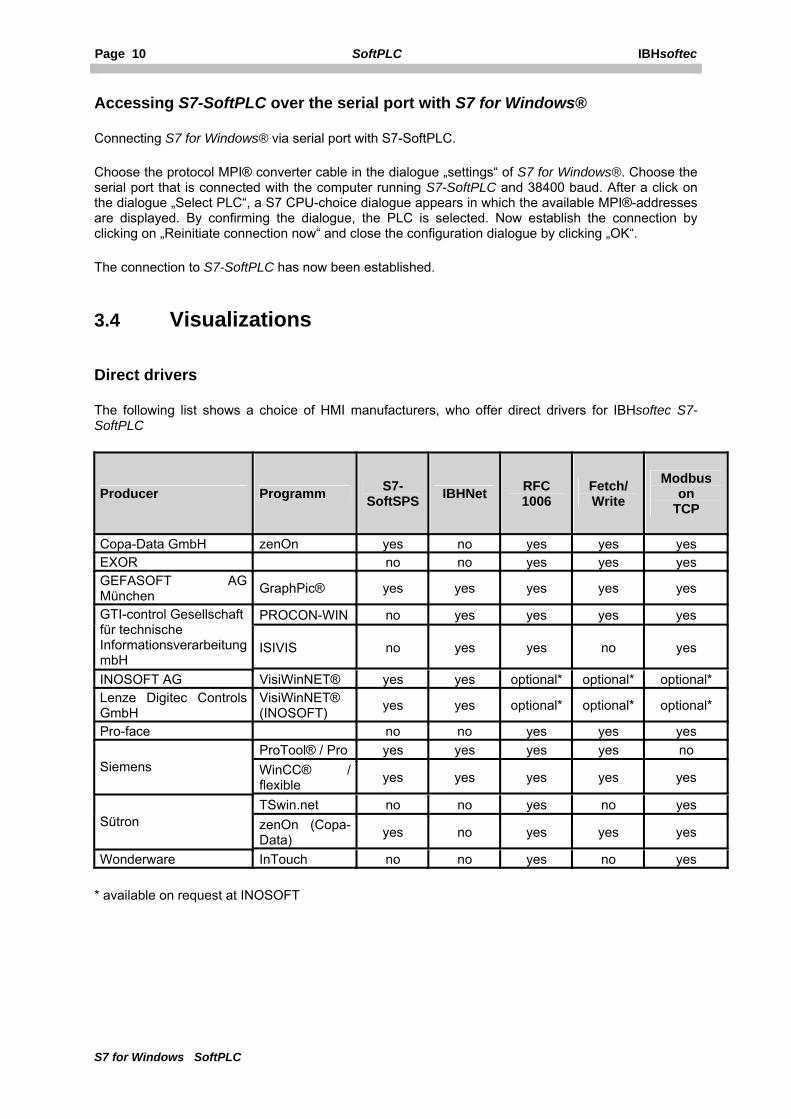
3.4 Visualizations Direct drivers
The following list shows a choice of HMI manufacturers, who offer direct drivers for IBHsoftec S7-SoftPLC
Producer Programm S7-SoftSPS IBHNet RFC
1006 Fetch/ Write
Modbus on
TCP
Copa-Data GmbH zenOn yes no yes yes yes EXOR no no yes yes yes GEFASOFT AG München GraphPic® yes yes yes yes yes
PROCON-WIN no yes yes yes yes GTI-control Gesellschaft für technische Informationsverarbeitung mbH
ISIVIS no yes yes no yes
INOSOFT AG VisiWinNET® yes yes optional* optional* optional*Lenze Digitec Controls GmbH
VisiWinNET® (INOSOFT) yes yes optional* optional* optional*
Pro-face no no yes yes yes ProTool® / Pro yes yes yes yes no
Siemens WinCC® / flexible yes yes yes yes yes
TSwin.net no no yes no yes Sütron zenOn (Copa-
Data) yes no yes yes yes
Wonderware InTouch no no yes no yes
* available on request at INOSOFT

IBHsoftec SoftPLC Page 11
S7 for Windows SoftPLC
IBHNet
The S7-SoftPLC can be accessed via the IBHNet driver, with every visualization software, that supports the IBHNet protocol. The IBHNet driver is available at http://www.ibhsoftec-sps.de/ as free download.
If an HMI package has implemented an own direct driver for the IBHLink S7 (NetLink) protocol, it can access the S7-SoftPLC as well, since this protocol (NL_MPI) is supported by the S7-SoftPLC too.
In addition there is the possibility, that an own visualization (e.g. Visual® BASIC or other high level languages) can establish a communication via the IBHNet-object, which is installed with the IBHNet driver. Details on this are contained in the IBHNet documentation.
RFC1006
To connect a HMI package to S7-SoftPLC via RFC1006 is possible, if the Ethernet CP-343/443 emulation of the S7-SoftPLC has been started.
Accessing S7-SoftPLC over Profibus with operator panels
The use of Hilscher Profibus® Master Cards is required. The Profibus must be configured over MPI® like on an hardware PLC first. In the case of S7-SoftPLC this can happen direct, serial or via TCP/IP. If the Profibus is operational, the option „OnlineDP“ can be activated in the driver configuration, to allow access to the S7-SoftPLC via Profibus.
OPC Server
A connection to S7-SoftPLC from an HMI package with the IBHsoftec OPC server or other OPC servers, which support the mentioned protocols,is possible as well.
3.5 Data interface to S7-SoftPLC
S7-SoftPLC can be accessed directly by various high level languages (e.g. Visual Basic®, Visual C/C++® or Borland C++Builder®). The DLL required for this (PLC32.DLL) is installed with S7-SoftPLC. The PLC32.DLL is a 32 Bit application.
Below the available functions for a data exchange are described.

Page 12 SoftPLC IBHsoftec
S7 for Windows SoftPLC
Data transmitting functions Read a single value
Reads a value from S7-SoftPLC.
unsigned long int DLLexport ReadVal (unsigned long int type,
unsigned long int no,
unsigned long int DBNo,
unsigned long int size,
unsigned long int far * val);
parameter description comment 'I' = input 'Q' = output 'M' = flag 'C'= counter value 16-bit-access only 'T' = timer value 16-bit-access only 'D' = data word or double dataword
depending on size
'B' = data bit, word, double wordon byte address
depending on size
compatible to S7 only
type
'P' = P_Parameter S7 from version 3 only no address Byte address of read in operand DBNo Number of data block 1 16383
Number of bits 0..7 = bit no 0 7 'I', 'Q', 'M' only 8 = 1 byte 16 = 1 wort
size
32 = 1 double word val Read value Pointer to a valid variable in the user applications
address space return 0 on error Error messages
Length of parameter list (Visual-C): 20 bytes.

IBHsoftec SoftPLC Page 13
S7 for Windows SoftPLC
Write a single value
Writes a value in S7-SoftSPS.
unsigned long int DLLexport WriteVal (unsigned long int type,
unsigned long int no,
unsigned long int DBNo,
unsigned long int size,
unsigned long int far * val);
parameter description comment 'I' = input 'Q' = output 'M' = flag 'C' = counter value 16-bit-access only 'T' = timer value 16-bit-access only 'D' = data word or double data word depending on size
'B' = data bit, byte, wort, doppelwort onbyte address
depending on size
compatible to S7 only
type
'P' = P_Parameter S7 from version 3 only no address Byte address of operand to be written DBNo number of data block 1 16383
number of bits 0..7 = bit no 0 7 'I', 'Q', 'M' only 8 = 1 byte 16 = 1 wort
size
32 = 1 double word val value to be written return 0 on error Error messages
Length of parameter list (Visual-C): 20 bytes.

Page 14 SoftPLC IBHsoftec
S7 for Windows SoftPLC
Read multiple values
Reads multiple values from S7-SoftPLC.
unsigned long int DLLexport ReadVals (unsigned long int type,
unsigned long int no,
unsigned long int DBNo,
unsigned long int size,
unsigned char far * vals);
parameter description comment 'I' = input 'Q' = output 'M' = flag 'D' = data word S5 compatible
type
'B' = data byte on byte address compatible to S7 only no address DBNo number of data block 1 16383 size number of data bytes or data words destination size in bytes for type 'I', 'Q', 'M' and 'B',
destination size in data words for 'D' vals Value of byte Pointer to a valid array in the user applications
address space
WARNING: ARRAY HAS TO BE BIG ENOUGH!
return 0 on error Error messages
Length of parameter list (Visual-C): 20 bytes.
WARNING: FOR DATA BLOCKS (TYPE 'D') THE ARRAY HAS TO BE TWICE AS BIG, SINCE 2 BYTES ARE NECESSARY FOR EVERY DATA WORD!

IBHsoftec SoftPLC Page 15
S7 for Windows SoftPLC
Write multiple values
Writes multiple values to S7-SoftPLC.
unsigned long int DLLexport WriteVals (unsigned long int type,
unsigned long int no,
unsigned long int DBNo,
unsigned long int size,
unsigned char far * vals);
parameter description comment 'I' = input 'Q' = output 'M' = flag 'D' = data word S5 compatible
type
'B' = data byte on byte address compatible to S7 only no address DBNo number of data block 1 16383
number of data bytes or data words 'I' Destination size in bytes 'Q' Destination size in bytes 'M' Destination size in bytes 'B' Destination size in bytes
size
'D' Destination size in data words vals value of byte Pointer to a valid array in the user applications
address space
WARNING: ARRAY HAS TO BE BIG ENOUGH!
return 0 on error Error messages
Length of parameter list (Visual-C): 20 bytes.
WARNING: FOR DATA BLOCKS (TYPE = D) THE ARRAY HAS TO BE TWICE AS BIG, SINCE 2 BYTES ARE NECESSARY FOR EVERY DATA WORD!
Page 16 SoftPLC IBHsoftec
S7 for Windows SoftPLC
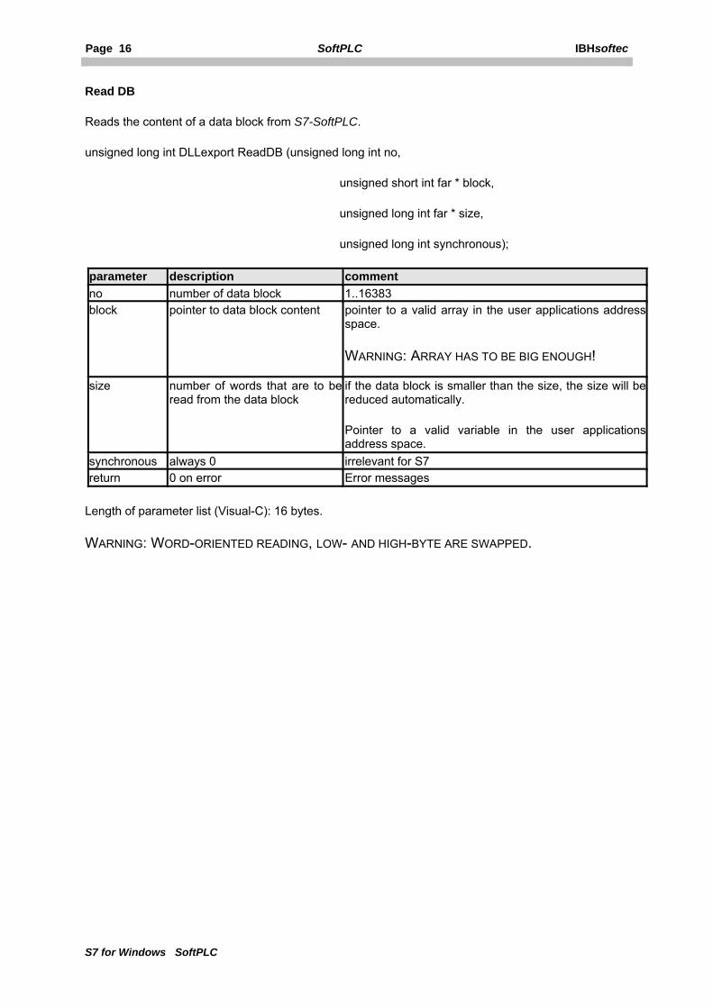
Read DB
Reads the content of a data block from S7-SoftPLC.
unsigned long int DLLexport ReadDB (unsigned long int no,
unsigned short int far * block,
unsigned long int far * size,
unsigned long int synchronous);
parameter description comment no number of data block 1..16383 block pointer to data block content pointer to a valid array in the user applications address
space.
WARNING: ARRAY HAS TO BE BIG ENOUGH!
size number of words that are to be read from the data block
if the data block is smaller than the size, the size will be reduced automatically.
Pointer to a valid variable in the user applications address space.
synchronous always 0 irrelevant for S7 return 0 on error Error messages
Length of parameter list (Visual-C): 16 bytes.
WARNING: WORD-ORIENTED READING, LOW- AND HIGH-BYTE ARE SWAPPED.

IBHsoftec SoftPLC Page 17
S7 for Windows SoftPLC
Write DB
Writes a data block to S7-SoftPLC.
unsigned long int DLLexport WriteDB (unsigned long int no,
unsigned short int far * block,
unsigned long int far * size,
unsigned long int synchronous);
parameter description comment no number of data block 1..16383 block pointer to data block content Pointer to a valid array in the user applications address
space
WARNING: ARRAY HAS TO BE BIG ENOUGH!
size number of words that are to be written into the block
if the data block is smaller than the size, the size will be reduced automatically.
Pointer to a valid variable in the user applications address space.
synchronous always 0 irrelevant for S7 return 0 on error Error messages
Length of parameter list (Visual-C): 16 bytes.
WARNING: WORD-ORIENTED WRITING, LOW- AND HIGH-BYTE ARE SWAPPED.

Page 18 SoftPLC IBHsoftec
S7 for Windows SoftPLC
Read S7 DB
Reads the content of a S7 data block from the PLC (byte oriented).
unsigned long int DLLexport ReadDB_S7 (unsigned long int no,
unsigned char int far * block,
unsigned long int far * size);
parameter description comment no number of data block 1..16383 block pointer to data block content Pointer to a valid array in the user applications address
space
WARNING: ARRAY HAS TO BE BIG ENOUGH!
size number of bytes that are to be read into the block
if the data block is smaller than the size, the size will be reduced automatically.
Pointer to a valid variable in the user applications address space.
return 0 on error Error messages
Length of parameter list (Visual-C): 12 bytes.
Write S7 DB
Writes the content of a S7 data block in the PLC (byte-oriented).
unsigned long int DLLexport WriteDB_S7 (unsigned long int no,
unsigned char int far * block,
unsigned long int far * size);
parameter description comment no number of data block 1..16383 blcok pointer to data block content Pointer to a valid array in the user applications address
space
WARNING: ARRAY HAS TO BE BIG ENOUGH!
size number of bytes that are to be written into the block
if the data block is smaller than the size, the size will be reduced automatically.
Pointer to a valid variable in the user applications address space.
return 0 on error Error messages
Length of parameter list (Visual-C): 12 bytes.

IBHsoftec SoftPLC Page 19
S7 for Windows SoftPLC
Functions for data conversion FloatToMC5
Converts floating point numbers from IBM-PC-format into S7 double words.
void DLLexport FloatToMC5 (float FloatValue,
unsigned long far * MC5Val);
parameter description comment FloatVal floating point number in IEEE- or INTEL-format MC5Val floating point number in Siemens-S7-format
MC5ToFloat
Converts S7 double words into floating point numbers in IBM-PC-format.
void DLLexport MC5ToFloat (unsigned long far * MC5Val,
float FloatVal);
parameter description comment MC5Val floating point number in Siemens-S7-format FloatVal floating point number in IEEE- or INTEL-format Accessing with a web server
If you are intending to access S7-SoftPLC with web applications(IIS), which should have access to the process data, please contact our support for examples. The S7-SoftPLC installs an object, which allows data access from script languages (VB Sript, J Script).

Page 20 SoftPLC IBHsoftec
S7 for Windows SoftPLC
4 Interface and configuration
There are two different views of S7-SoftPLC.
The first, called classic view in the following text, shows cycle times and allows to switch S7-SoftPLC to RUN/STOP.
The second is called configuration interface and allows to choose the used interface driver and to alter S7-SoftPLC settings.
4.1 Classic View
This is the standard view of IBHsoftec S7-SoftPLC. Here the number of cycles, as well as the cycle times and jitter of the actual PLC program can be seen. Available load memory, free load memory, PLC type, serial number, version, name and organization of the user are displayed as well. The classic view provides the possibility to restart, stop or close the S7-SoftPLC. Loading and saving the PLC-program into the installation folder, changing to the configuration view and locking the user interface to prevent unauthorised access is also possible.

IBHsoftec SoftPLC Page 21
S7 for Windows SoftPLC
Warm restart (OB100)
Activating the button „Warm restart“, starts the PLC-program. First the organisation block OB 100 is processed. After this the cyclic program-processing starts with OB1.This is similar to the start-up of a hardware PLC after a voltage-return.
Hot restart (OB101)
Activating the button „Hot restart“, starts the PLC-program. First the organisation block OB 101 is processed. After this the cyclic program-processing starts with OB1. This is similar to the start-up of a hardware PLC after manual switching from STOP to RUN.
PLC Stop
Activating the button „Stop“, stops the cyclic program-processing. In the operating mode "STOP" the PLC-program is not processed. The status of the process images, flags, counters and timers, remain in the current state.
Terminate PLC
Activating the button „Terminate PLC“, terminates the program. A restart of the S7-SoftPLC is possible at any time.
Cycles
The number of program-cycles is displayed here
Cycle times [ms]
The time a program-cycle needs is monitored continuously by S7-SoftPLC.
The minimum, maximum and current cycle time of the current PLC-program are displayed. The resolution of a cycle time-measurement is one millisecond.
The cycle time of a PLC depends on the program structure. At the end of a cycle S7-SoftPLC saves the result of the cycle time-measurement. This is the time, that has past between two OB1 calls.
The time of a cycle (OB1 Cycle time) can be read out with the PLC-program.
OB 1/LW6:
current cycle time in ms
(OB1_PREV_CYCLE)
OB 1/LW8:
maximum cycle time in ms
(OB1_MIN_CYCLE)
OB 1/LW10:
minimum cycle time in ms
(OB1_MAX_CYCLE)
Jitter
Jitter is the variation in the cycle time of the S7-SoftPLC caused by the system itself.
If an output pulse from a timer OB (e.g. OB 10, every 10 ms) is measured, differences may be found. Jitter is the variation in time between the current measurement, relative to the previously measured time. You will see jitter with hardware and software PLC’s.
With S7-SoftPLC the jitter may be caused by programmed program-interrupts such as process alarms and also may occur due to hard disk access, network access, etc (system activities).

Page 22 SoftPLC IBHsoftec
S7 for Windows SoftPLC
The Jitter of the S7-SoftPLC is constantly measured. The maximum jitter and the actual jitter is displayed.
Load memory
The load memory is the maximum size in bytes, that a PLC-programm may use. The free load memory is the size, that is still available and can be used by additional blocks. If to few free load memory is available, the PU can not transmit new blocks to S7-SoftPLC.
Lock settings
A manipulation of S7-SoftPLC by the user can be prevented with a password.
To lock S7-SoftPLC activate the button „Lock settings“.
Now unauthorised access to the S7-SoftPLC is prevented.
NOTE: THE LOCKING HAS NO INFLUENCE ON THE PROGRAM SEQUENCE OF S7-SOFTPLC.
Enable settings
The locked S7-SoftPLC is enabled again.
To unlock S7-SoftPLC activate the button „Enable settings“.
The S7-SoftPLC user interface can now be used to alter S7-SoftPLC configuration.
Change password
Changes the password.
After activating the button „Change password“ a dialogue appears, where the old and two times the new password have to be entered to confirm the change.
The password has now been changed.
Configure
Switches the user interface to configuration mode.
After activating the button „Configure“ the interface changes its display into the configuration view. Here drivers can be chosen and parameterised. Inputs, outputs, flags and data blocks can be observed and basic settings can be altered.
The S7-SoftPLC can now be configured.
Load
The PLC-program currently saved in the file „S7.BIN“ in S7-SoftPLC's installation folder will be loaded into S7-SoftPLC.
Save
The PLC-program currently loaded in S7-SoftPLC will be saved as „S7.BIN“ in the installation folder of S7-SoftPLC.

IBHsoftec SoftPLC Page 23
S7 for Windows SoftPLC
PLC type
Purchase order numbers compatible to S7-SoftSPS:
6ES7 315-1AF01-0AB0 S7-SoftPLC 315 without Profibus 6ES7 315-2AG10-0AB0
S7-SoftPLC 315 with Profibus
6ES7 416-1XJ02-0AB0 S7-SoftPLC 416 without Profibus 6ES7 416-2XK02-0AB0 S7-SoftPLC 416 with Profibus Serial number
The serial number of the installed S7-SoftPLC
Version
Number of version fo the installed S7-SoftPLC
Name
Name of licence owner
Organisation
License owners organization/company name

Page 24 SoftPLC IBHsoftec
S7 for Windows SoftPLC
4.2 Configuration view
In this view the user has the possibility to configure S7-SoftPLC parameters, choose and parameterise drivers and observe inputs, outputs, flags and data blocks.
Menu
The Menu offers the possibility to save and open configuration files. Furthermore the display can be switched back to the „Classic view“ or other setting windows can be displayed. This help file and the IBHsoftec GmbH contact informations are also available over the menu.
Toolbar
The tool bar provides quick access to often used menu item.
Config tree
The config tree shows an overview of selected drivers and the CPU Parameter view.
To get to the desired setting, mark a tree element with the mouse.
The chosen tree entry is now displayed in the setting window.
Setting window
Here the selected element can be edited.
Help window
A short help for the current element is displayed here.
4.3 Menu
The menu is divided into the following four areas:
• File • Edit • View • Help

IBHsoftec SoftPLC Page 25
S7 for Windows SoftPLC
4.3.1 File menu
Open SoftPLC configuration
Shows an „Open file“-dialogue to choose the desired configuration file (PLC43.INI). It will be loaded to the user interface.
Save SoftPLC configuration
Saves the current S7-SoftPLC configuration into the installation folder of S7-SoftPLC.
Save SoftPLC configuration as
Opens a „Save file as“-dialogue to save the configuration file (PLC43.INI) in a different path.
Restart SoftPLC
Closes S7-SoftPLC and restarts it.
Terminate SoftPLC
Terminates S7-SoftPLC.
Exit SoftPLC and configuration
Terminates S7-SoftPLC and the user interface.
Exit configuration
Closes the user interface.
Page 26 SoftPLC IBHsoftec
S7 for Windows SoftPLC
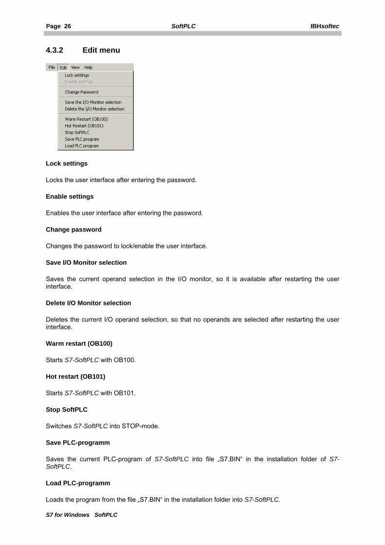
4.3.2 Edit menu
Lock settings
Locks the user interface after entering the password.
Enable settings
Enables the user interface after entering the password.
Change password
Changes the password to lock/enable the user interface.
Save I/O Monitor selection
Saves the current operand selection in the I/O monitor, so it is available after restarting the user interface.
Delete I/O Monitor selection
Deletes the current I/O operand selection, so that no operands are selected after restarting the user interface.
Warm restart (OB100)
Starts S7-SoftPLC with OB100.
Hot restart (OB101)
Starts S7-SoftPLC with OB101.
Stop SoftPLC
Switches S7-SoftPLC into STOP-mode.
Save PLC-programm
Saves the current PLC-program of S7-SoftPLC into file „S7.BIN“ in the installation folder of S7-SoftPLC.
Load PLC-programm
Loads the program from the file „S7.BIN“ in the installation folder into S7-SoftPLC.

IBHsoftec SoftPLC Page 27
S7 for Windows SoftPLC
4.3.3 View menu
Classic view
Switches the interface from „Configuration“ to „Classic“.
The other entries select the view of the respective configuration window.
4.3.4 Help menu
Open manual
Opens the S7-SoftPLC manual.
Info about S7-SoftPLC...
Opens an about box.

Page 28 SoftPLC IBHsoftec
S7 for Windows SoftPLC
4.4 Toolbar
Open SoftPLC configuration
Shows an „Open file“-dialogue to choose the desired configuration file (PLC43.INI). It will be loaded to the user interface.
Save SoftPLC configuration
Saves the current S7-SoftPLC configuration into the installation folder of S7-SoftPLC.
Save SoftPLC configuration as
Opens a „Save file as“-dialogue to save the configuration file (PLC43.INI) in a different path.
Warm restart (OB 100)
Starts S7-SoftPLC with OB100.
Hot restart (OB101)
Starts S7-SoftPLC with OB101.
Stop SoftPLC
Switches S7-SoftPLC into STOP-mode.
Save SoftPLC binary file
Saves the current PLC-program of S7-SoftPLC into file „S7.BIN“ in the installation folder of S7-SoftPLC.
Load SoftPLC binary file
Loads the program from the file „S7.BIN“ in the installation folder into S7-SoftPLC.
Cold restart to accept changes in configuration
Terminates S7-SoftPLC and restarts it.
Open manual
Opens the S7-SoftPLC manual
About
Opens a window in which the number of version of S7-SoftPLC and the IBHsoftec contact information are presented.

IBHsoftec SoftPLC Page 29
S7 for Windows SoftPLC
4.5 I/O monitor
This dialogue allows to observe data areas from S7-SoftPLC.
There are two (2) tabs, IQM for input, outputs, and flags and data blocks.
IQM
The concurrent display of ten (10) byte is possible. By selecting a field, it is assigned to input-byte, output-byte or flag-byte. The checkboxes are to be understood as a switch with lamps. Chekced state indicates, that a byte is set (logical one). The button can be (re)set by the process (user program) or by clicking.

Page 30 SoftPLC IBHsoftec
S7 for Windows SoftPLC
Data Blocks
Dynamic display of a data block and its content. The value of byte, word or double word can be changed decimal or hexadecimal with the button „Change value“.

IBHsoftec SoftPLC Page 31
S7 for Windows SoftPLC
5 Configuration
This chapter describes the S7-SoftPLC configuration.
• CPU parameters • Add/remove driver • Addidata • Beckhoff TwinCAT I/O • CIF30/50/60 • CP343/CP443 emulation • I/O Port • Modbus on TCP • NVRAM • Softnet PN I/O • User SFC
5.1 CPU parameters
Here the basic settings for S7-SoftPLC are performed.
• Configuration with the help of the user interface • Configuration in the PLC43.INI
5.1.1 User Interface
In this window the basic settings of S7-SoftPLC are performed.
Page 32 SoftPLC IBHsoftec
S7 for Windows SoftPLC
Load PLC-program at startup
The currently saved PLC-program, stored in „S7.BIN“ in the S7-SoftPLC installation folder, is loaded into S7-SoftPLC, as soon as it is started. The display of the jitter is reseted.
If the option „Load PLC program at startup“ is selected, the PLC-program saved in the file „S7.BIN“ is loaded into S7-SoftPLC when S7-SoftPLC is started. The starting conforms to the start-up of a hardware-PLC after a voltage-return. Therefor the organisation block OB 101 is processed first. After that the cyclic program-processing starts with OB 1. The signal states of flags(M), timers(T) and counters(C) are restored into S7-SoftPLC, if this is set in the hardware configuration.
If any problems should occur at the next start, delete the file „S7.BIN“ in the installation directory of S7-SoftPLC. Such problems may occur, if the saving process has been disturbed. In such case the PLC-program has to be downloaded again with the programming unit. In such case the flags(M), timers(T) and counters(C) are in their initial state.
Save PLC programm at shutdown
The PLC-programm located in S7-SoftPLC is saved into the file „S7.BIN“ in the S7-SoftPLC installation folder, as soon as S7-SoftPLC is terminated. The signal states of flags(M), timers(T) and counters(C) are saved as well.
Retain M/T/C (Select the areas with the S7-Hardware-Configurator)
The memory is kept remanent for M,T,C. (starting at byte 0 up to the value set with the hardware configuration)
Permit saving in RUN
Permits saving without stoping the PLC.
WARNING: IF THE PROGRAM IS SAVED DURING A RUNNING OPERATION, THE CYCLE TIME CAN RISE.
Single processor mode (also Hyperthreading CPUs)
Sets the single processor mode fixed. With real double or dual-core processors the PLC has got 25% of the possible computing time. This option should be activated with Hyperthreading processors, otherwise the processor capacity and the cycle time can vary.
Key switch position
RUN In this mode S7-SoftPLC processes the PLC-program. RUN-P In this mode S7-SoftPLC processes the PLC-program. The PLC-program can be
modified during operation.

IBHsoftec SoftPLC Page 33
S7 for Windows SoftPLC
Operating system
Selection of used operating system
Language
Selection of user interface language.
MPI via serial interface
The connection to S7-SoftPLC can be established over the selected port.
PLC memory size
The size of the SoftPLC S7-416 load memory. The size of the SoftPLC S7-315 load memory is limited to 256 kbyte.
PLC : Windows processor time (ms)
Partitioning of the PC-CPU processing time between S7-SoftPLC and Windows®.
Default
Restores the default settings.

Page 34 SoftPLC IBHsoftec
S7 for Windows SoftPLC
5.1.2 CPU parameters of S7-SoftPLC
In this section the basic settings of S7-SoftPLC are entered.
keyname values default value
description
OS NT4 / W2K
W2K Used operating system
NT4 = WinNT4, W2K = Win2000/XP LANGUAGE DEU /
ENG DEU user interface language of the S7-SoftPLC
DEU = german, ENG = english MPI 0 .. 4 0 Used port
0 = Internal, 1 = COM1, 2 = COM2, etc... LOAD 0 / 1 0 0 = Do not load PLC program at start-up
1 = Load PLC program from S7.BIN at start-up STORE 0 / 1 0 0 = Do not save PLC program at shut down
1 = Save PLC program in S7.BIN at shut down S7_STORE 50000...
end of PC memory
500000 Size of load memory in bytes
The S7-SoftPLC 315 has a limited load memory of 297225 byte
STORE_NO_STOP 0 / 1 0 1 = Save without stopping the PLC
WARNING: IF THE PROGRAM IS SAVED DURING A RUNNING OPERATION, THE CYCLE TIME CAN RISE.
REM 0 / 1 0 1 = Memory is kept remanent for M,T,C (starting at byte 0 up to the value set with hardware configation).
KEY_SWITCH 1 / 2 2 1 = Signals the PU, that the key switch is set to RUN, no block downloading possible 2 = Signals the PU, that the key switch is set to RUN-P.
NOMP 0 / 1 0 1 = Sets the single processor mode fixed. With real double or dual-core processors the PLC has got 25% computing time. This option should be activated with hyperthreading processors, otherwise the processor load and the cycle time can vary.
WINTIME 1 .. 8 1 Reserved CPU processing time for Windows in ms 3 = 3 ms Windows and 1 ms PLC, which corresponds to 75% processing time for Windows and 25% for S7-SoftPLC.

IBHsoftec SoftPLC Page 35
S7 for Windows SoftPLC
5.2 Add/remove drivers
Here drivers are added or removed from S7-SoftPLC
• Add/remove drivers with the help of user interface • Add/remove drivers in the PLC43.INI
5.2.1 Add/remove drivers...
Here the hardware drivers for S7-SoftPLC can be added/removed.
The available drivers are listed one the left side, the drivers currently assigned to S7-SoftPLC on the right side.
Add drivers
Select a driver for S7-SoftPLC.
Activate the „>>“-button and the highlighted driver moves to the right area (Selected drivers) and is therefore added to S7-SoftPLC.
After a restart of S7-SoftPLC the driver is now available.

Page 36 SoftPLC IBHsoftec
S7 for Windows SoftPLC
Remove drivers
Remove a driver from the S7-SoftPLC configuration.
Activate the „<<“-button and the highlighted driver moves to the left area (Available drivers) and is therefore removed from S7-SoftPLC. The drivers can again be added to S7-SoftPLC at any time.
After a restart of S7-SoftPLC the driver is not available any more.
WARNING: IF A DRIVER WITH NON AVAILABLE HARDWARE IS SELECTED, FAILURES OF S7-SOFTPLC CAN OCCUR.
5.2.2 Add/remove drivers to S7-SoftPLC
In the section [OEM] the necessary hardware driver DLLs are listed. Up to 10 driver DLLs can be loaded.
Key name
Value area Default value
Description
DLL0 CIF30D0.DLL --- When using a Hilscher CIF-card DLL1 CIFCFG.DLL --- The driver CIFCFG.DLL is needed to configure the
Profibus with the Siemens SIMATIC® Manager or S7 for Windows® hardware configuration. This driver provides the online functions via Profibus and DPV1 services as well. The driver can only be used together with the first CIF-card.
DLL2 .. DLL9
--- --- More card drivers
There are 2 possibilities to configure the field bus components:
If a Profibus® master-station is supposed to be configured over the S7 for Windows® hardware configuration or the Step7® hardware configuration, the following driver entries in the section [OEM] are to be selected:
[OEM]
DLL0=CIF30D0.DLL
DLL1=CIFCFG.DLL
These entries assure, that the Profibus® configuration, created with the S7 for Windows® hardware configuration or the Step7® hardware configuration, is analysed and that the CIF module (Profibus® only) is configured automatically during start-up.
If multiple Profibus®-cards are supposed to run in one PC, only the first card can be automatically configured. All other cards must be parameterised with the Hilscher System Configurator SyCon.
If other CIF field bus cards (e.g. Interbus, CAN) are to be used, always the Hilscher System Configurator SyCon has to be used, because the S7 for Windows® hardware configurat
IBHsoftec SoftPLC Page 37
S7 for Windows SoftPLC
ion or the Step7® hardware configuration do not support the other bus systems.
Furthermore the following system parameters have to be set in the System Configurator SyCon under “setup”:
• Controlled release of communication by the application program • Byte addresses • Little Endian (LSB-MSB) • Buffered, host controlled
In the section [OEM] the following has to be selected:
[OEM]
DLL0=CIF30D0.DLL
For compatibility reasons to existing applications, the classic driver cif30x0.dll, as used in version 2.x of S7-SoftPLC for a long time, is still being delivered and installed, but not integrated by default. Applications that did not use the diagnostic blocks SFB210 and SFB252, can change to the driver Cif30D(n).dll without any problems. If this change is too complex, the classic driver can still be used.
5.3 Addidata
With the help of the ADDIPACK driver S7-SoftPLC can access Addidata I/O cards
• Accessing Addidata I/O cards in the PLC-program • Configuring the driver with the help of the user interface • Configuring the driver in the PLC43.INI
5.3.1 ADDI-DATA configuration
The ADDI-DATA-driver allows to access Digital I/O and Analog I/O cards from the PLC-program of S7-SoftPLC. With the ADDI-PACK software the physical IO-cards are mapped into a single virtual card. It can be accessed over functions (FC-blocks), which need to be called from the PLC-program. A cyclic data exchange over the process image does not make sense, due to the ADDI-DATA functions infrastructure.
Requirements
• The interface card has to be installed on the computer. • The adequate drivers of ADDI-DATA have to be installed. • The software ADDIPACK has to be installed and correctly licenced. • The interface card has to be configured in the ADDI-PACK.
(if there are any problems, please contact the ADDI-DATA documentation and/or the ADDI-DATA support.)
• The „ADDI-DATA PC-Card“ driver has to be selected in S7-SoftPLC.
Page 38 SoftPLC IBHsoftec
S7 for Windows SoftPLC
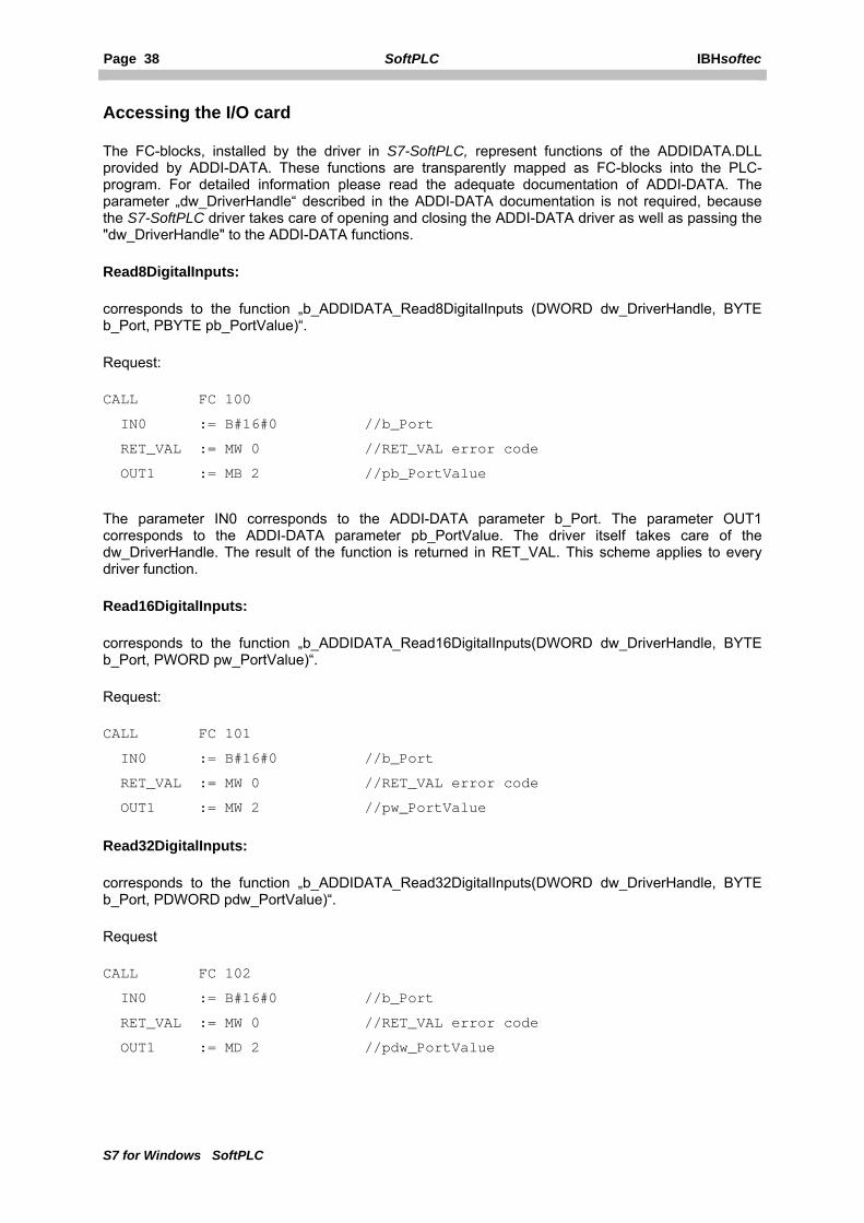
Accessing the I/O card
The FC-blocks, installed by the driver in S7-SoftPLC, represent functions of the ADDIDATA.DLL provided by ADDI-DATA. These functions are transparently mapped as FC-blocks into the PLC-program. For detailed information please read the adequate documentation of ADDI-DATA. The parameter „dw_DriverHandle“ described in the ADDI-DATA documentation is not required, because the S7-SoftPLC driver takes care of opening and closing the ADDI-DATA driver as well as passing the "dw_DriverHandle" to the ADDI-DATA functions.
Read8DigitalInputs:
corresponds to the function „b_ADDIDATA_Read8DigitalInputs (DWORD dw_DriverHandle, BYTE b_Port, PBYTE pb_PortValue)“.
Request:
CALL FC 100
IN0 := B#16#0 //b_Port
RET_VAL := MW 0 //RET_VAL error code
OUT1 := MB 2 //pb_PortValue
The parameter IN0 corresponds to the ADDI-DATA parameter b_Port. The parameter OUT1 corresponds to the ADDI-DATA parameter pb_PortValue. The driver itself takes care of the dw_DriverHandle. The result of the function is returned in RET_VAL. This scheme applies to every driver function.
Read16DigitalInputs:
corresponds to the function „b_ADDIDATA_Read16DigitalInputs(DWORD dw_DriverHandle, BYTE b_Port, PWORD pw_PortValue)“.
Request:
CALL FC 101
IN0 := B#16#0 //b_Port
RET_VAL := MW 0 //RET_VAL error code
OUT1 := MW 2 //pw_PortValue
Read32DigitalInputs:
corresponds to the function „b_ADDIDATA_Read32DigitalInputs(DWORD dw_DriverHandle, BYTE b_Port, PDWORD pdw_PortValue)“.
Request
CALL FC 102
IN0 := B#16#0 //b_Port
RET_VAL := MW 0 //RET_VAL error code
OUT1 := MD 2 //pdw_PortValue

IBHsoftec SoftPLC Page 39
S7 for Windows SoftPLC
Set8DigitalOutputs:
corresponds to the function „b_ADDIDATA_Set8DigitalOutputsOn(DWORD dw_DriverHandle, BYTE b_Port, BYTE b_PortValue)“.
Request:
CALL FC 103
IN0 := B#16#0 //b_Port
IN1 := B#16#0 //b_PortValue
RET_VAL := MW 0 //RET_VAL error code
Set16DigitalOutputs:
corresponds to the function „b_ADDIDATA_Set16DigitalOutputsOn(DWORD dw_DriverHandle, BYTE b_Port, WORD w_PortValue)“.
Request:
CALL FC 104
IN0 := B#16#0 //b_Port
IN1 := W#16#0 //w_PortValue
RET_VAL := MW 0 //RET_VAL error code
Set32DigitalOutputs:
corresponds to the function „b_ADDIDATA_Set32DigitalOutputsOn(DWORD dw_DriverHandle, BYTE b_Port, DWORD dw_PortValue)“.
Request:
CALL FC 105
IN0 := B#16#0 //b_Port
IN1 := DW#16#0 //dw_PortValue
RET_VAL := MW 0 //RET_VAL error code
InitAnalogInput:
corresponds to the function „b_ADDIDATA_InitAnalogInput(DWORD dw_DriverHandle, WORD w_Channel, pstr_InitAnalogInput ps_InitParameters, DWORD dw_StructSize)“.
This function expects a data structure for the initialisation of an input (see card documentation). The structure is passed to the FC with an ANY-pointer of the type byte (ps_InitParameters). A seperate parameter for length of the structure (dw_StructSize) is not neccessary, it is taken from the ANY-pointer.
Request:
CALL FC 106
IN0 := W#16#0 //w_Channel
IN1 := P#M 8.0 BYTE 10 //ANY-pointer to structure
RET_VAL := MW 0 //RET_VAL error code

Page 40 SoftPLC IBHsoftec
S7 for Windows SoftPLC
ReleaseAnalogInput:
corresponds to the function „b_ADDIDATA_ReleaseAnalogInput(DWORD dw_DriverHandle, WORD w_Channel)“.
Request
CALL FC 107
IN0 := W#16#0 //w_Channel
RET_VAL := MW 0 //RET_VAL error code
InitAnalogOutput:
corresponds to the function „b_ADDIDATA_Init1AnalogOutput(DWORD dw_DriverHandle, WORD w_Channel, BYTE b_VoltageMode, BYTE b_Polarity)“.
Request:
CALL FC 108
IN0 := W#16#0 //w_Channel
IN1 := B#16#0 //b_VoltageMode
IN2 := B#16#0 //b_Polarity
RET_VAL := MW 0 //RET_VAL error code
ReadAnalogInput:
corresponds to the function „b_ADDIDATA_Read1AnalogInput(DWORD dw_DriverHandle, WORD w_Channel, DWORD dw_ConvertingTime, BYTE b_ConvertingTimeUnit, BYTE b_InterruptFlag, PDWORD pdw_ChannelValue)“.
The function expects a pointer to the return value (see card documentation). The structure is passed to the FC with an ANY-Pointer of the type dword (pdw_ChannelValue). Please notice, that the ANY-Pointer always has to have the length of DWORD 3 (12 byte).
The parameter b.InterruptFlag is not used, because it runs in Polling-mode only.
Request:
CALL FC 109
IN0 := W#16#0 //w_Channel
IN1 := DW#16#0 //dw_ConvertingTime
IN2 := B#16#0 //b_ConvertingTimeUnit
IN3 := P#M4.0 DWORD 3 //ANY-pointer to result
RET_VAL := MW 0 //RET_VAL error code
WriteAnalogOutput:
corresponds to the function „b_ADDIDATA_Write1AnalogOutput(DWORD dw_DriverHandle, WORD w_Channel, dw_ValueToWrite)“.
Request:

IBHsoftec SoftPLC Page 41
S7 for Windows SoftPLC
CALL FC 110
IN0 := W#16#0 //w_Channel
IN1 := DW#16#0 //dw_ValueToWrite
RET_VAL := MW 0 //RET_VAL error code
Return values:
On success RET_VAL = 0 is returned.
If an error has occurred, the error code from ADDIDATA.DLL is passed through, if possible.
If it should not be possible, the following error codes are returned:
Error code Reason 0x807F DriverHandle not available 0x8042 Error reading input 0x8043 Error writing output 0x8003 Wrong ANY-Pointer type 0x8023 ANY-Pointer does not point to a valid area or does not have the correct length
PLC switches to STOP:
If S7-SoftPLC is switched to STOP by the driver, an error code is inserted into the diagnostic buffer, which can be read out with the programming unit (S7 für Windows®, STEP® 7).
Error code Reason 0xA140 An error has occured at “i_ADDIDATA_OpenWin32Driver”. The error number of
ADDIDATA.DLL is following in the next diagnostic buffer entry.

Page 42 SoftPLC IBHsoftec
S7 for Windows SoftPLC
5.3.2 Configuring the ADDI-DATA driver
Initialise ADDI-DATA driver once (not with every PLC Start/Stop)
Initialise the ADDI-DATA driver at first start of S7-SoftPLC, not at every RUN/STOP transition.
FC-numbers can be assigned to the ADDI-DATA functions. (It must be pointed out, that a unique number is assigned to every FC-block!)
Function "b_ADDIDATA_FunctionName" mapped to FC:
Number of the FC, that corresponds to the ADDIPACK function "b_ADDIDATA_funktion name".
Status:
Shows the ADDI-DATA driver status of the computer.

IBHsoftec SoftPLC Page 43
S7 for Windows SoftPLC
5.3.3 ADDI-DATA driver for S7-SoftPLC
In order to activate the driver, the driver is included in the form dll0=addi_data.dll in the section [OEM].
The driver expects the section [addi_data], in which further parameters can be defined.
Name of parameter Default value Description Read8FC 100 Number of FC Read8DigitalInputs Read16FC 101 Number of FC Read16DigitalInputs Read32FC 102 Number of FC Read32DigitalInputs Set8FC 103 Number of FC Set8DigitalOutputs Set16FC 104 Number of FC Set16DigitalOutputs Set32FC 105 Number of FC Set32DigitalOutputs InitAnaInpFC 106 Number of FC InitAnalogInput RelAnaInpFC 107 Number of FC ReleaseAnalogInput InitAnaOutFC 108 Number of FC InitAnalogOutput ReadAnaInpFC 109 Number of FC ReadAnalogInput WriteAnaOutFC 110 Number of FC WriteAnalogOutput NoStop 0 0 = Driver is initialised at every PLC-
START
1 = Driver is initialised once
It must be pointed out, that a unique number is assigned to every FC-block!
Example:
[OEM]
dll0=addi_data.dll
[addi_data]
Read8FC=100
Read16FC=101
Read32FC=102
Set8FC=103
Set16FC=104
Set32FC=105
InitAnaInpFC=106
RelAnaInpFC=107
InitAnaOutFC=108
ReadAnaInpFC=109
WriteAnaOutFC=110
NoStop=0

Page 44 SoftPLC IBHsoftec
S7 for Windows SoftPLC
5.4 Beckhoff TwinCAT I/O
With the Beckhoff TwinCAT I/O driver, every fieldbus system supported by Beckhoff, can be accessed from S7-SoftPLC.
• Creating a task in the TwinCAT System Manager • Accessing a task (peripherals) from S7-SoftPLC • Configuring driver with the help of the user interface • Configuring driver in the PLC43.INI
5.4.1 Beckhoff TwinCAT I/O configuration
The driver allows to exchange I/O data with S7-SoftPLC via the Beckhoff TwinCAT I/O driver. With the TwinCAT I/O driver every I/O component supported by Beckhoff can be accessed, so that this driver is independent from the used fieldbus.
To access the Beckhoff peripheral components with S7-SoftPLC, the TwinCAT I/O driver from Beckhoff has to be installed and licensed on the computer.
The I/O tasks, that are supposed to be used with S7-SoftPLC, must be configured with the Beckhoff TwinCAT System Manager.
The TwinCatIO.dll maps the process images to the Beckhoff I/O components. Acyclic accesses via peripheral commands are as well possible as the acyclic access with a SFC/FC.
In order to use the driver, the following steps are necessary:
• Inserting a station in TwinCAT System Manager • Creating a task in TwinCAT System Manager • Accessing ADS-functions from the PLC-program

IBHsoftec SoftPLC Page 45
S7 for Windows SoftPLC
Inserting a station in TwinCAT System Manager
With a right-click on I/O Devices >> Scan Devices... a dialogue appears in which an I/O component can be selected (if it is available in the net).
After having selected the desired device, TwinCAT System Manager asks, whether to scan for new boxes.

Page 46 SoftPLC IBHsoftec
S7 for Windows SoftPLC
If agreed, all available I/O components will be scanned. The I/O components are now known to the TwinCAT I/O and can be accessed.
Creating a task in the TwinCAT System Manager
With a right-click on Additional Tasks >> Append Task... a new task is created. The task represents the S7-SoftPLCs process images.
Important task settings
Port: The port with the number 301 normally serves as process image for S7-SoftPLC. It is also accessible over a SFC/FC.
AutoStart: S7-SoftPLC triggers the fieldbus and thus informs the TwinCAT driver, that it is still operational. The option AutoStart normally must not be chosen.
If this option is selected, the TwinCAT I/O driver has to be configured in such a way, that it can independently detect, whether the PLC is still operational, in order to switch the outputs of the I/O components into a defined state, if necessary.
IBHsoftec SoftPLC Page 47
S7 for Windows SoftPLC
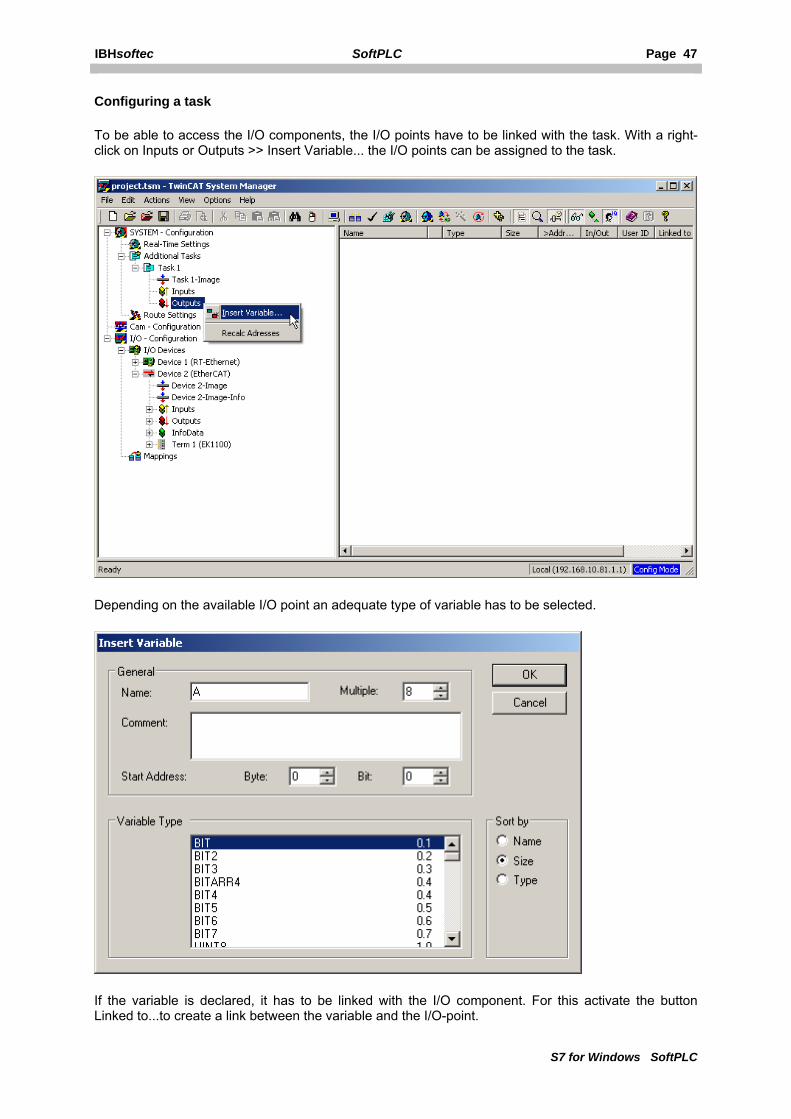
Configuring a task
To be able to access the I/O components, the I/O points have to be linked with the task. With a right-click on Inputs or Outputs >> Insert Variable... the I/O points can be assigned to the task.
Depending on the available I/O point an adequate type of variable has to be selected.
If the variable is declared, it has to be linked with the I/O component. For this activate the button Linked to...to create a link between the variable and the I/O-point.

Page 48 SoftPLC IBHsoftec
S7 for Windows SoftPLC
If the set of variables is linked with the task, the configuration has to be activated. Thereafter the TwinCAT I/O-task is ready for use, as soon as it is switched into Run-Mode.
IBHsoftec SoftPLC Page 49
S7 for Windows SoftPLC
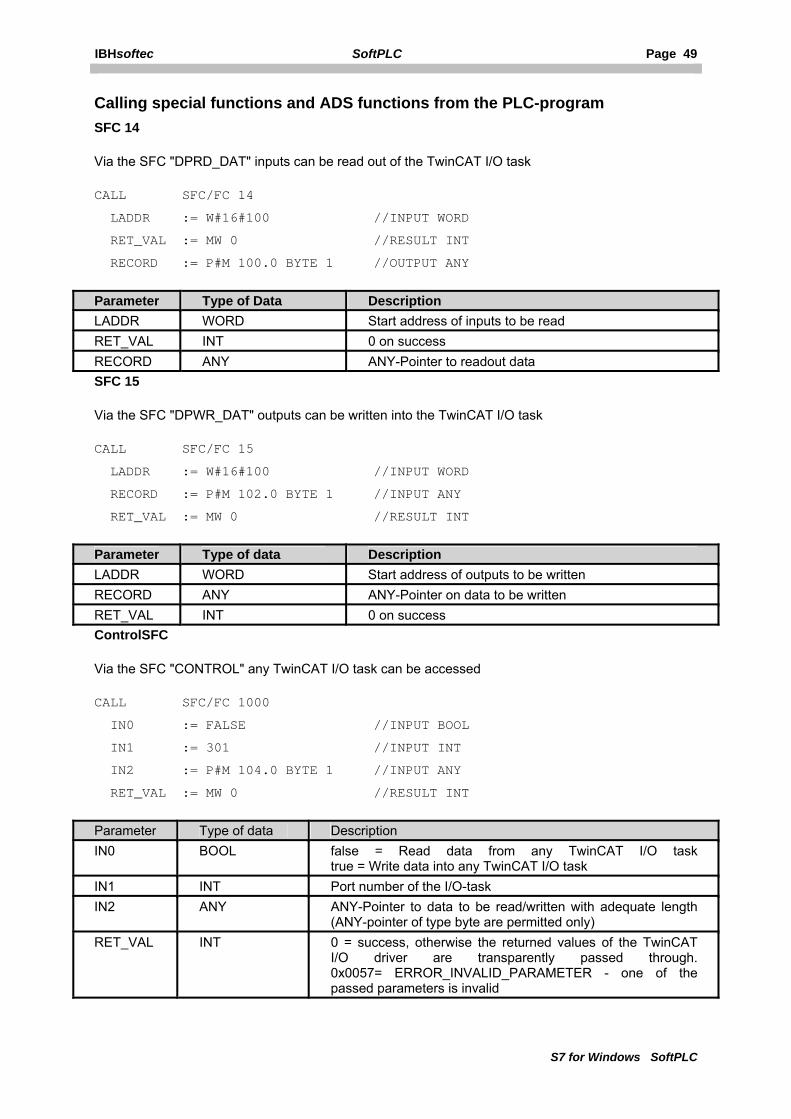
Calling special functions and ADS functions from the PLC-program SFC 14
Via the SFC "DPRD_DAT" inputs can be read out of the TwinCAT I/O task
CALL SFC/FC 14
LADDR := W#16#100 //INPUT WORD
RET_VAL := MW 0 //RESULT INT
RECORD := P#M 100.0 BYTE 1 //OUTPUT ANY
Parameter Type of Data Description LADDR WORD Start address of inputs to be read RET_VAL INT 0 on success RECORD ANY ANY-Pointer to readout data SFC 15
Via the SFC "DPWR_DAT" outputs can be written into the TwinCAT I/O task
CALL SFC/FC 15
LADDR := W#16#100 //INPUT WORD
RECORD := P#M 102.0 BYTE 1 //INPUT ANY
RET_VAL := MW 0 //RESULT INT
Parameter Type of data Description LADDR WORD Start address of outputs to be written RECORD ANY ANY-Pointer on data to be written RET_VAL INT 0 on success ControlSFC
Via the SFC "CONTROL" any TwinCAT I/O task can be accessed
CALL SFC/FC 1000
IN0 := FALSE //INPUT BOOL
IN1 := 301 //INPUT INT
IN2 := P#M 104.0 BYTE 1 //INPUT ANY
RET_VAL := MW 0 //RESULT INT
Parameter Type of data Description IN0 BOOL false = Read data from any TwinCAT I/O task
true = Write data into any TwinCAT I/O task IN1 INT Port number of the I/O-task IN2 ANY ANY-Pointer to data to be read/written with adequate length
(ANY-pointer of type byte are permitted only) RET_VAL INT 0 = success, otherwise the returned values of the TwinCAT
I/O driver are transparently passed through. 0x0057= ERROR_INVALID_PARAMETER - one of the passed parameters is invalid
Page 50 SoftPLC IBHsoftec
S7 for Windows SoftPLC
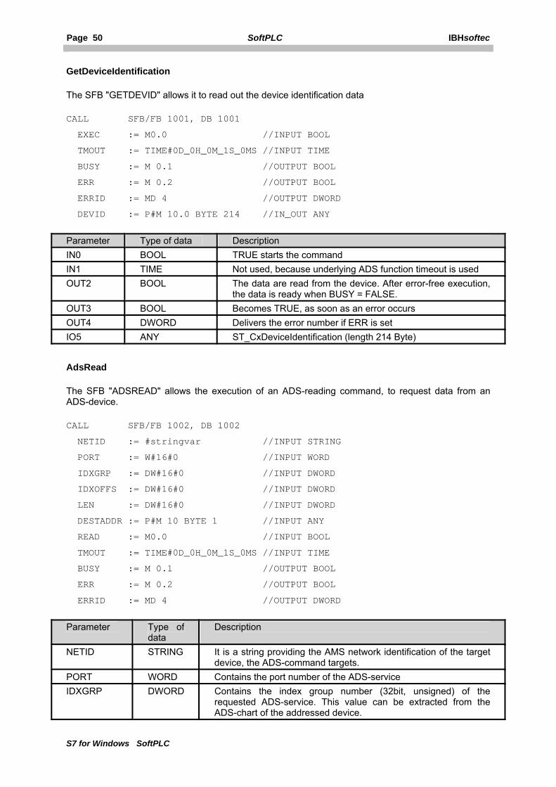
GetDeviceIdentification
The SFB "GETDEVID" allows it to read out the device identification data
CALL SFB/FB 1001, DB 1001
EXEC := M0.0 //INPUT BOOL
TMOUT := TIME#0D_0H_0M_1S_0MS //INPUT TIME
BUSY := M 0.1 //OUTPUT BOOL
ERR := M 0.2 //OUTPUT BOOL
ERRID := MD 4 //OUTPUT DWORD
DEVID := P#M 10.0 BYTE 214 //IN_OUT ANY
Parameter Type of data Description IN0 BOOL TRUE starts the command IN1 TIME Not used, because underlying ADS function timeout is used OUT2 BOOL The data are read from the device. After error-free execution,
the data is ready when BUSY = FALSE. OUT3 BOOL Becomes TRUE, as soon as an error occurs OUT4 DWORD Delivers the error number if ERR is set IO5 ANY ST_CxDeviceIdentification (length 214 Byte)
AdsRead
The SFB "ADSREAD" allows the execution of an ADS-reading command, to request data from an ADS-device.
CALL SFB/FB 1002, DB 1002
NETID := #stringvar //INPUT STRING
PORT := W#16#0 //INPUT WORD
IDXGRP := DW#16#0 //INPUT DWORD
IDXOFFS := DW#16#0 //INPUT DWORD
LEN := DW#16#0 //INPUT DWORD
DESTADDR := P#M 10 BYTE 1 //INPUT ANY
READ := M0.0 //INPUT BOOL
TMOUT := TIME#0D_0H_0M_1S_0MS //INPUT TIME
BUSY := M 0.1 //OUTPUT BOOL
ERR := M 0.2 //OUTPUT BOOL
ERRID := MD 4 //OUTPUT DWORD
Parameter Type of data
Description
NETID STRING It is a string providing the AMS network identification of the target device, the ADS-command targets.
PORT WORD Contains the port number of the ADS-service IDXGRP DWORD Contains the index group number (32bit, unsigned) of the
requested ADS-service. This value can be extracted from the ADS-chart of the addressed device.

IBHsoftec SoftPLC Page 51
S7 for Windows SoftPLC
IDXOFFS DWORD Contains the index offset number (32bit, unsigned) of the requested ADS-service. This value can be extracted from the ADS-chart of the addressed device.
LEN DWORD Contains the number of data to be read in bytes. DESTADDR ANY Pointer to the destination buffer. The buffer needs to be big
enough to record LEN bytes. The buffer can be a single variable, an array or a structure.
READ BOOL On TRUE ADS-command is executed TMOUT TIME Timeout BUSY BOOL This output is TRUE as long as a ADS command is executed.
Resetted by timeout or success. While BUSY=TRUE, no new command is accepted.
ERR BOOL This output is TRUE, if an error has occurred during the execution of an ADS command. The command-specific error code is contained in "ERRID". If a timeout has occured, "ERR" = TRUE and "ERRID" = 1861 (hexadecimal 0x745). A new command resets "ERR".
ERRID DWORD Contains the command-specific error code of the last executed command. A new command resets "ERRID"
AdsWrite
The SFB "ADSWRITE" allows the execution of an ADS-writing command, to transmit data to an ADS-device.
CALL SFB/FB 1003, DB 1003
NETID := #stringvar //INPUT STRING
PORT := W#16#0 //INPUT WORD
IDXGRP := DW#16#0 //INPUT DWORD
IDXOFFS := DW#16#0 //INPUT DWORD
LEN := DW#16#0 //INPUT DWORD
SRCADDR := P#M 10.0 BYTE 1 //INPUT ANY
WRITE := M0.0 //INPUT BOOL
TMOUT := TIME#0D_0H_0M_0S_0MS //INPUT TIME
BUSY := M 0.1 //OUTPUT BOOL
ERR := M 0.2 //OUTPUT BOOL
ERRID := MD 4 //OUTPUT DWORD
Parameter Type of data
Description
NETID STRING It is a string providing the AMS network identification of the target device, the ADS-command targets.
PORT WORD Contains the port number of the ADS-service IDXGRP DWORD Contains the index group number (32bit, unsigned) of the requested
ADS-service. This value can be extracted from the ADS-chart of the addressed device.
IDXOFFS DWORD Contains the index group number (32bit, unsigned) of the requested ADS-service. This value can be extracted from the ADS-chart of the addressed device.
LEN DWORD Contains the number of data to be written in bytes.

Page 52 SoftPLC IBHsoftec
S7 for Windows SoftPLC
SRCADDR ANY Pointer to the source buffer. The buffer needs to be big enough to hold LEN bytes. The buffer can be a single variable, an array or a structure.
WRITE BOOL On TRUE ADS-command is executed TMOUT TIME Timeout BUSY BOOL This output is TRUE as long as a ADS command is executed.
Resetted by timeout or success. While BUSY=TRUE, no new command is accepted.
ERR BOOL This output is TRUE, if an error has occurred during the execution of an ADS command. The command-specific error code is contained in "ERRID". If a timeout has occured, "ERR" = TRUE and "ERRID" = 1861 (hexadecimal 0x745). A new command resets "ERR".
ERRID DWORD Contains the command-specific error code of the last executed command. A new command resets "ERRID"
5.4.2 Configuring TwinCAT I/O drivers
Default
Resets the default values.

IBHsoftec SoftPLC Page 53
S7 for Windows SoftPLC
Don't stop fieldbus on PLC stop (only set outputs to 0)
Instead of stoping the fieldbus at PLC STOP completely, all outputs are set to 0.
Show TwinCAT SFCs as FCs
Defines, whether blocks should be displayed as FCs or SFCs in S7-SoftPLC.
Show SFC 14/15
Shows SFC 14/15.
Port Number (as defined in the Twincat System Manager)
Port number of the TwinCAT I/O task, normally 301.
Control SFC Number (additional Ports)
Block number of the Control SFC to read or write data from/to additional tasks.
FB "GetDeviceIdentification" Number
Block number of the FB "GetDeviceIdentification".
FB "AdsRead" Number
Block number of the FB "AdsRead".
FB "AdsWrite Number
Block number of the FB "AdsWrite".
Load configuration from TwinCAT System Manager
In order to avoid double documentation and to be able to reuse symbols, a converter exits, that allows to covert Step® 7 symbols from symbolic table (*.SEQ) data into I/O-tasks. And to inversely convert symbols from I/O-tasks into symbolic tables.
Existing symbolic tables can be applied to existing tasks with multiple options.
Export symbolic tables out of the symbol editor with Step® 7.
• Open symbolic table in Step® 7 symbol editor. • Select menu item "Table -> export". • Select "Allocation map (*.SEQ)" format in the following dialogue.
Import symbolic tables with Step® 7 symbol editor.
• Open symbolic table in Step® 7 symbol editor. • Select menu item "Table -> import". • Select "Allocation map (*.SEQ)" format in the following dialogue. • S7 for Windows® projects generally work with SEQ files. Therefore a symbol file with the
same name has to be generated only, to be exchanged via the Windows® Explorer.
Page 54 SoftPLC IBHsoftec
S7 for Windows SoftPLC
Existing IO Tasks
In this window, I/O tasks and loaded System Manager files (.tsm) are displayed.
By highlighting an I/O task, it is loaded, so that it can be exported into a symbolic table.
Open System Manager file
Loads a System Manager file (.tsm) into the dialogue, to export the available symbols into a symbolic table.
Export into symbolic table
Exports the loaded I/O task into a symbolic table (.seq).
Open symbolic table
Loads a symbolic table (.seq) into the dialogue, to export the contained symbols into a I/O task.
Apply symbolic table to task
Exports the loaded symbols into a System Manager file (.tsm.).
Content of symbolic table
Shows the loaded symbols of a System Manager file (.tsm) or a symbolic table (.seq).
Using a Beckhoff EtherCAT®->Profibus coupler
The Beckhoff EtherCAT®->Profibus coupler has got a fixed 100ms-KBus-watchdog. Without this fixed setting the Profibus would not clock correctly any more. Minimum cycle is < 100ms, if BKs/KLs are used.
That means there has to be one task, that is quicker than 100ms and has the highest priority, because the task with the highest priority triggers the Profibus®.
IBHsoftec SoftPLC Page 55
S7 for Windows SoftPLC
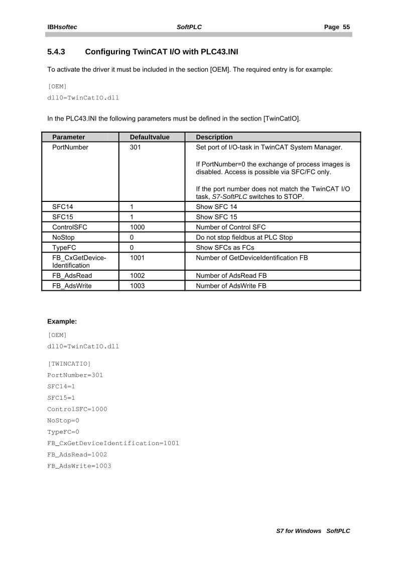
5.4.3 Configuring TwinCAT I/O with PLC43.INI
To activate the driver it must be included in the section [OEM]. The required entry is for example:
[OEM]
dll0=TwinCatIO.dll
In the PLC43.INI the following parameters must be defined in the section [TwinCatIO].
Parameter Defaultvalue Description PortNumber 301 Set port of I/O-task in TwinCAT System Manager.
If PortNumber=0 the exchange of process images is disabled. Access is possible via SFC/FC only.
If the port number does not match the TwinCAT I/O task, S7-SoftPLC switches to STOP.
SFC14 1 Show SFC 14 SFC15 1 Show SFC 15 ControlSFC 1000 Number of Control SFC NoStop 0 Do not stop fieldbus at PLC Stop TypeFC 0 Show SFCs as FCs FB_CxGetDevice-Identification
1001 Number of GetDeviceIdentification FB
FB_AdsRead 1002 Number of AdsRead FB FB_AdsWrite 1003 Number of AdsWrite FB
Example:
[OEM]
dll0=TwinCatIO.dll
[TWINCATIO]
PortNumber=301
SFC14=1
SFC15=1
ControlSFC=1000
NoStop=0
TypeFC=0
FB_CxGetDeviceIdentification=1001
FB_AdsRead=1002
FB_AdsWrite=1003
Page 56 SoftPLC IBHsoftec
S7 for Windows SoftPLC
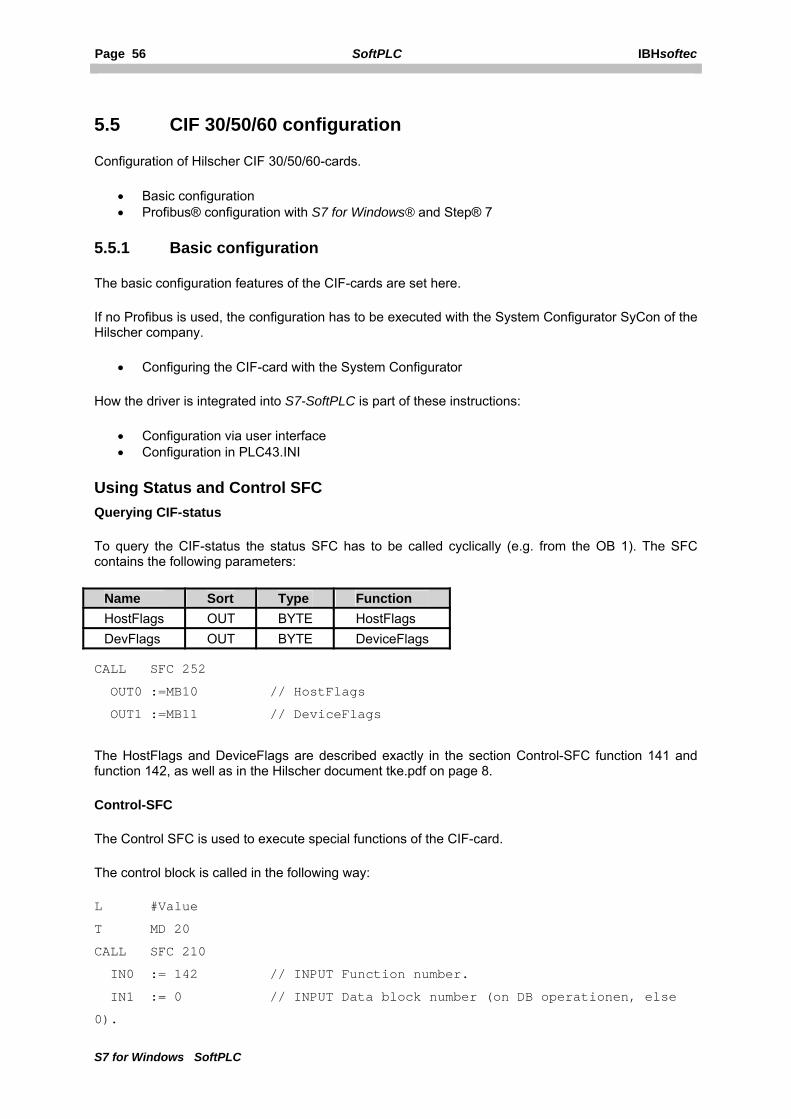
5.5 CIF 30/50/60 configuration
Configuration of Hilscher CIF 30/50/60-cards.
• Basic configuration • Profibus® configuration with S7 for Windows® and Step® 7
5.5.1 Basic configuration
The basic configuration features of the CIF-cards are set here.
If no Profibus is used, the configuration has to be executed with the System Configurator SyCon of the Hilscher company.
• Configuring the CIF-card with the System Configurator
How the driver is integrated into S7-SoftPLC is part of these instructions:
• Configuration via user interface • Configuration in PLC43.INI
Using Status and Control SFC Querying CIF-status
To query the CIF-status the status SFC has to be called cyclically (e.g. from the OB 1). The SFC contains the following parameters:
Name Sort Type Function HostFlags OUT BYTE HostFlags DevFlags OUT BYTE DeviceFlags
CALL SFC 252
OUT0 :=MB10 // HostFlags
OUT1 :=MB11 // DeviceFlags
The HostFlags and DeviceFlags are described exactly in the section Control-SFC function 141 and function 142, as well as in the Hilscher document tke.pdf on page 8.
Control-SFC
The Control SFC is used to execute special functions of the CIF-card.
The control block is called in the following way:
L #Value
T MD 20
CALL SFC 210
IN0 := 142 // INPUT Function number.
IN1 := 0 // INPUT Data block number (on DB operationen, else
0).
IBHsoftec SoftPLC Page 57
S7 for Windows SoftPLC
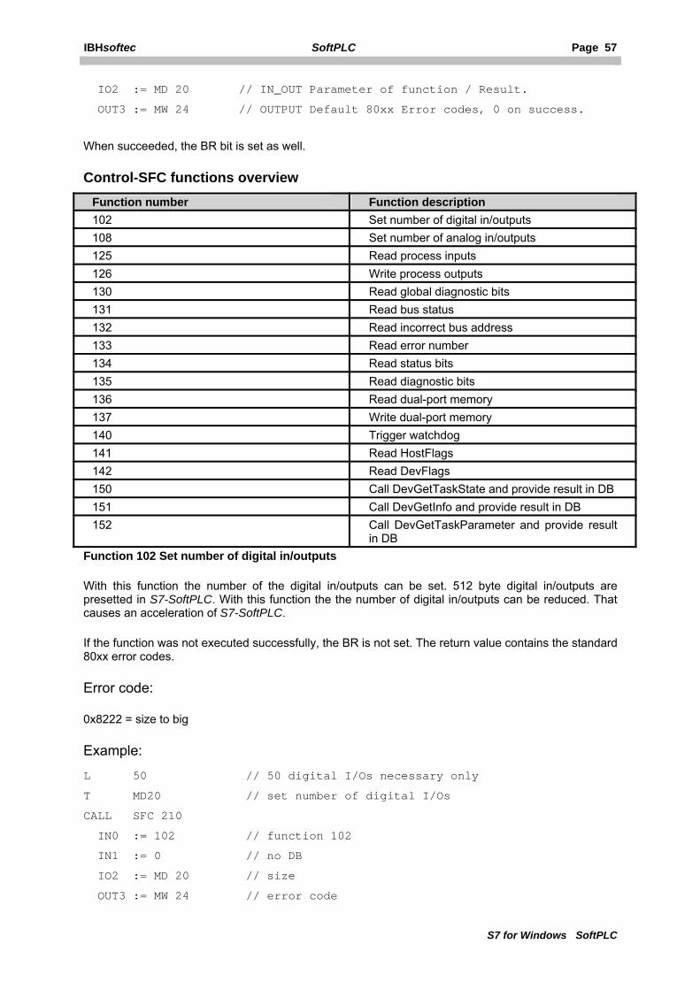
IO2 := MD 20 // IN_OUT Parameter of function / Result.
OUT3 := MW 24 // OUTPUT Default 80xx Error codes, 0 on success.
When succeeded, the BR bit is set as well.
Control-SFC functions overview Function number Function description 102 Set number of digital in/outputs 108 Set number of analog in/outputs 125 Read process inputs 126 Write process outputs 130 Read global diagnostic bits 131 Read bus status 132 Read incorrect bus address 133 Read error number 134 Read status bits 135 Read diagnostic bits 136 Read dual-port memory 137 Write dual-port memory 140 Trigger watchdog 141 Read HostFlags 142 Read DevFlags 150 Call DevGetTaskState and provide result in DB 151 Call DevGetInfo and provide result in DB 152 Call DevGetTaskParameter and provide result
in DB Function 102 Set number of digital in/outputs
With this function the number of the digital in/outputs can be set. 512 byte digital in/outputs are presetted in S7-SoftPLC. With this function the the number of digital in/outputs can be reduced. That causes an acceleration of S7-SoftPLC.
If the function was not executed successfully, the BR is not set. The return value contains the standard 80xx error codes.
Error code:
0x8222 = size to big
Example:
L 50 // 50 digital I/Os necessary only
T MD20 // set number of digital I/Os
CALL SFC 210
IN0 := 102 // function 102
IN1 := 0 // no DB
IO2 := MD 20 // size
OUT3 := MW 24 // error code

Page 58 SoftPLC IBHsoftec
S7 for Windows SoftPLC
Function 108 Set number of analog in/outputs
With this function the number of the analog in/outputs can be set. The maximum size of the dualport RAM, found during the initialization of the card, is presetted in S7-SoftPLC. With this function the number of analog in/outputs can be reduced to the required number. It is counted from byte 0 of the dualport. If the function was not executed successfully, the BR is not set. The return value contains the standard 80xx error codes.
Fehlercode:
0x8222 = Size to big
Example:
L 100 // 100 analog I/Os necessary only
T MD20 // set number of analog I/Os
CALL SFC 210
IN0 := 108 // function 108
IN1 := 0 // no DB
IO2 := MD 20 // size
OUT3 := MW 24 // error code
Function 125 Read process inputs
With this function the process inputs can be read into a data block. Herewith every available peripheral byte can be accessed.
The function writes asynchronous. With word oriented inputs no data consistence exists and the function can only be used with byte oriented inputs.If the function was not executed successfully, the BR is not set. The return value contains the standard 80xx error codes.
Error codes:
0x813A = data block not available
0x8222 = size of data block bigger than size of source area
0x8042 = READY or COM missing
0x807F = internal driver access error
Example:
L W#16#0100 // process input start address
T MD20
CALL SFC 210
IN0 := 125 // function 125
IN1 := 300 // DB 300
IO2 := MD 20 // process input start address
OUT3 := MW 24 // error code
IBHsoftec SoftPLC Page 59
S7 for Windows SoftPLC
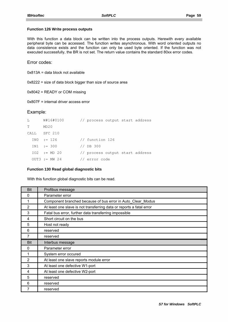
Function 126 Write process outputs
With this function a data block can be written into the process outputs. Herewith every available peripheral byte can be accessed. The function writes asynchronous. With word oriented outputs no data consistence exists and the function can only be used byte oriented. If the function was not executed successfully, the BR is not set. The return value contains the standard 80xx error codes.
Error codes:
0x813A = data block not available
0x8222 = size of data block bigger than size of source area
0x8042 = READY or COM missing
0x807F = internal driver access error
Example:
L W#16#0100 // process output start address
T MD20
CALL SFC 210
IN0 := 126 // function 126
IN1 := 300 // DB 300
IO2 := MD 20 // process output start address
OUT3 := MW 24 // error code
Function 130 Read global diagnostic bits
With this function global diagnostic bits can be read.
Bit Profibus message 0 Parameter error 1 Component branched because of bus error in Auto_Clear_Modus 2 At least one slave is not transferring data or reports a fatal error 3 Fatal bus error, further data transferring impossible 4 Short circuit on the bus 5 Host not ready 6 reserved 7 reserved Bit Interbus message 0 Parameter error 1 System error occured 2 At least one slave reports module error 3 At least one defective W1-port 4 At least one defective W2-port 5 reserved 6 reserved 7 reserved

Page 60 SoftPLC IBHsoftec
S7 for Windows SoftPLC
If the function was not executed successfully, the BR is not set. The return value contains the standard 80xx error codes.
Error codes:
0x807F = Internal driver access error
Example:
CALL SFC 210
IN0 := 130 // function 130
IN1 := 0 // no DB
IO2 := MD 20 // diagnostic bits
OUT3 := MW 24 // error code
Function 131 Read bus status
With this function the bus status can be read.
Bit Interbus message 0 Bus segment turned off 1 reserved 2 reserved 3 reserved 4 reserved 5 reserved 6 reserved 7 reserved
If the function was not executed successfully, the BR is not set. The return value contains the standard 80xx error codes.
Error codes:
0x807F = Internal driver access error
Example:
CALL SFC 210
IN0 := 131 // function 131
IN1 := 0 // no DB
IO2 := MD 20 // bus status
OUT3 := MW 24 // error code
Function 132 Read incorrect bus address
With this function the incorrect bus address can be read. If the function was not executed successfully, the BR is not set. The return value contains the standard 80xx error codes.
Error codes:
0x807F = Internal driver access error

IBHsoftec SoftPLC Page 61
S7 for Windows SoftPLC
Example:
CALL SFC 210
IN0 := 132 // function 132
IN1 := 0 // no DB
IO2 := MD 20 // incorrect bus address
OUT3 := MW 24 // error code
Function 133 Read error number
With this function the error number can be read. If the function was not executed successfully, the BR is not set. The return value contains the standard 80xx error codes.
Error codes:
0x807F = Internal driver access error
Example:
CALL SFC 210
IN0 := 133 // function 133
IN1 := 0 // no DB
IO2 := MD 20 // error number
OUT3 := MW 24 // error code
Function 134 Read status bits
With this function the status bits can be read. Before the call the status byte number (0..15) must be selected. After the function call, the selected status byte is returned. If a bit in status byte is 1, the corresponding slave is active, if it is 0, it is inactive. If the function was not executed successfully, the BR is not set. The return value contains the standard 80xx error codes.
Error codes:
0x807F = Internal driver access error
Example:
L W#16#03 // byte number 3
T MD20
CALL SFC 210
IN0 := 134 // function 134
IN1 := 0 // no DB
IO2 := MD 20 // before calling status byte nummer, after calling
the content of the status byte
OUT3 := MW 24 // error code
Function 135 Read diagnostic bits
With this function the diagnostic bits can be read. Before the call the diagnostic byte number (0..15) must be selected. After the function call, the selected diagnostic byte is returned. If a bit in the diagnostic byte is 1, the status of the corresponding slave has changed (from active to inactive or vice

Page 62 SoftPLC IBHsoftec
S7 for Windows SoftPLC
versa). If the function was not executed successfully, the BR is not set. The return value contains the standard 80xx error codes.
Error codes:
0x807F = Internal driver access error
Example:
L W#16#03 // byte number 3
T MD 20
CALL SFC 210
IN0 := 134 // function 134
IN1 := 0 // no DB
IO2 := MD 20 // before calling diagnostic byte number, after
calling the content of diagnostic byte
OUT3 := MW 24 // error code
Fkt 136 Read dual-port memory
With this function an area from the dual-port memory of the CIF-card can be written into a data block. Basically it begins with the first byte in the data block. The length is passed in the I/O-parameter low word and the relative address in the dual-port memory in the I/O-parameter high word. If the function was not executed successfully, the BR is not set. The return value contains the standard 80xx error codes.
Error codes:
0x813A = data block not available
0x8222 = size of data block to small
0x8224 = range overflow
0x8042 = READY or COM missing
0x807F = Internal driver access error
Example:
L DW#16#0100000A // copy 10 bytes from the relative address 100H
T MD20
CALL SFC 210
IN0 := 136 // function 136
IN1 := 60 // DB 60
IO2 := MD 20 // 10 bytes are read from the relative address
0x100H
OUT3 := MW 24 // error code
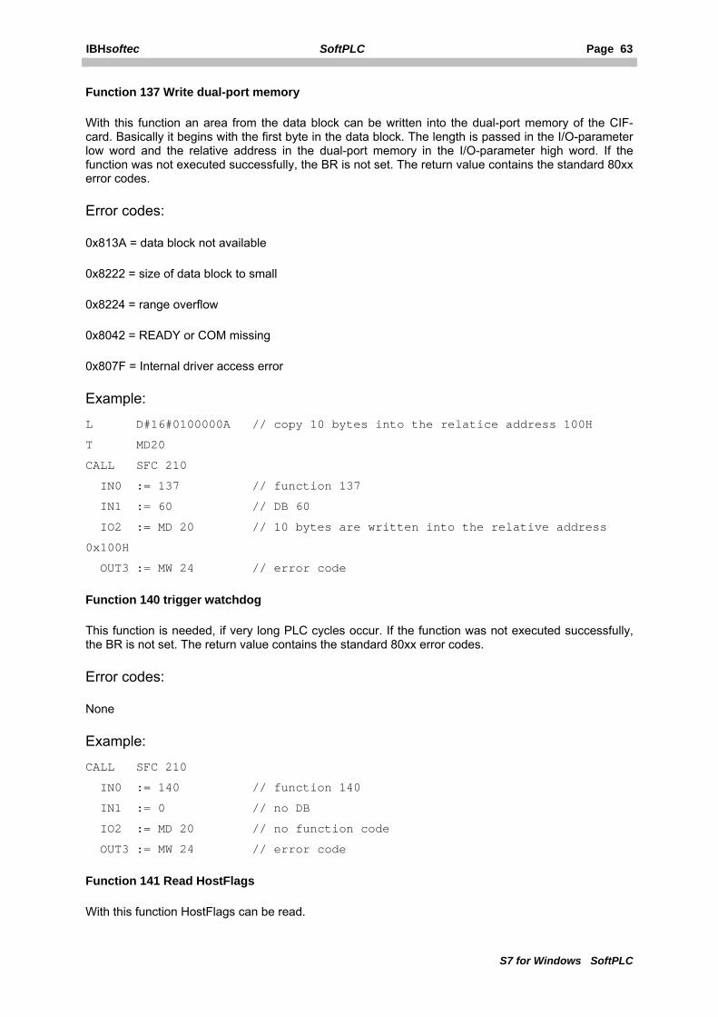
IBHsoftec SoftPLC Page 63
S7 for Windows SoftPLC
Function 137 Write dual-port memory
With this function an area from the data block can be written into the dual-port memory of the CIF-card. Basically it begins with the first byte in the data block. The length is passed in the I/O-parameter low word and the relative address in the dual-port memory in the I/O-parameter high word. If the function was not executed successfully, the BR is not set. The return value contains the standard 80xx error codes.
Error codes:
0x813A = data block not available
0x8222 = size of data block to small
0x8224 = range overflow
0x8042 = READY or COM missing
0x807F = Internal driver access error
Example:
L D#16#0100000A // copy 10 bytes into the relatice address 100H
T MD20
CALL SFC 210
IN0 := 137 // function 137
IN1 := 60 // DB 60
IO2 := MD 20 // 10 bytes are written into the relative address
0x100H
OUT3 := MW 24 // error code
Function 140 trigger watchdog
This function is needed, if very long PLC cycles occur. If the function was not executed successfully, the BR is not set. The return value contains the standard 80xx error codes.
Error codes:
None
Example:
CALL SFC 210
IN0 := 140 // function 140
IN1 := 0 // no DB
IO2 := MD 20 // no function code
OUT3 := MW 24 // error code
Function 141 Read HostFlags
With this function HostFlags can be read.
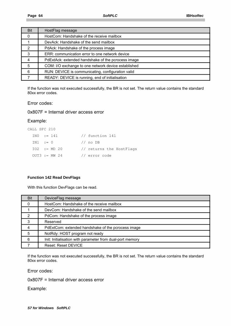
Page 64 SoftPLC IBHsoftec
S7 for Windows SoftPLC
Bit HostFlag message 0 HostCom: Handshake of the receive mailbox 1 DevAck: Handshake of the send mailbox 2 PdAck: Handshake of the process image 3 ERR: communication error to one network device 4 PdExtAck: extended handshake of the pcrocess image 5 COM: I/O exchange to one network device established 6 RUN: DEVICE is communicating, configuration valid 7 READY: DEVICE is running, end of initialisation
If the function was not executed successfully, the BR is not set. The return value contains the standard 80xx error codes.
Error codes:
0x807F = Internal driver access error
Example:
CALL SFC 210
IN0 := 141 // function 141
IN1 := 0 // no DB
IO2 := MD 20 // returns the HostFlags
OUT3 := MW 24 // error code
Function 142 Read DevFlags
With this function DevFlags can be read.
Bit DeviceFlag message 0 HostCom: Handshake of the receive mailbox 1 DevCom: Handshake of the send mailbox 2 PdCom: Handshake of the process image 3 Reserved 4 PdExtCom: extended handshake of the pcrocess image 5 NotRdy: HOST program not ready 6 Init: Initialisation with parameter from dual-port memory 7 Reset: Reset DEVICE
If the function was not executed successfully, the BR is not set. The return value contains the standard 80xx error codes.
Error codes:
0x807F = Internal driver access error
Example:

IBHsoftec SoftPLC Page 65
S7 for Windows SoftPLC
CALL SFC 210
IN0 := 142 // function 142
IN1 := 0 // no DB
IO2 := MD 20 // returns the DevFlags
OUT3 := MW 24 // error code
Function 150 Execute DevGetTaskState
With this function the global diagnostic infomation, reported from the CIF-module, can be read. The structure contains information about the bus condition and the condition of several slaves. The information is stored in bit-fields. In this way information about the master and the condition of the fieldbus is available. Furthermore it can be read, which slaves are configured and in use, which slaves are active and inactive and which slaves contain diagnostic information.
The driver function DevGetTaskState is called internally. The result is written into a DB. To be able to use the function, the information to the function should be extracted from the Hilscher manual dpm_pie.pdf. The DB should correspond to the DPM_DIAGNOSTICS structure described there. If the function was not executed successfully, the BR is not set. The return value contains the standard 80xx error codes.
Error codes:
0x813A = data block not available
0x8222 = size of data block to small
0x8225 = range overflow
0x807F = internal driver access error
Example:
L DW#16#2
T MD20 // task 2
CALL SFC 210
IN0 := 150 // function 150
IN1 := 300 // DB 300
IO2 := MD 20 // task number
OUT3 := MW 24 // error code
Adequate DB example:
DATA_BLOCK DB 300
TITLE=DIAG
VERSION : 0.1
STRUCT
bGlobalBits : BYTE;
bDPM_state : BYTE;
tError : STRUCT
bErr_Rem_Adr : BYTE;
bErr_Event : BYTE;

Page 66 SoftPLC IBHsoftec
S7 for Windows SoftPLC
END_STRUCT;
usBus_Error_Cnt : WORD;
usTime_Out_Cnt : WORD;
abReserved : ARRAY[0..7] OF BYTE;
abSl_cfg : ARRAY[0..15] OF BYTE;
abSl_state : ARRAY[0..15] OF BYTE;
abSl_diag : ARRAY[0..15] OF BYTE;
END_STRUCT;
BEGIN
END_DATA_BLOCK
Function 151 Execute DevGetInfo
With DevGetInfo various information can be read from the dual-port of the CIF-card. These are:
DW#16#1 GET_DRIVER_INFO Driver status information
DW#16#2 GET_VERSION_INFO version information of the CIF
DW#16#3 GET_FIRMWARE_INFO version of the CIF firmware
DW#16#4 GET_TASK_INFO Task information
DW#16#5 GET_RCS_INFO CIF specific operating system information
DW#16#6 GET_DEV_INFO Device information
DW#16#7 GET_IO_INFO Device I/O information
DW#16#8 GET_IO_SEND_DATA Device I/O send data
The driver function DevGetInfo is called internally. The result is written into a DB. To be able to use the function, the information to the function should be extracted from the Hilscher manual devdrv.pdf. The DB should correspond to the structures described there. If the function was not executed successfully, the BR is not set. The return value contains the standard 80xx error codes.
Error codes:
0x813A = data block not available
0x8222 = data block size to small
0x8225 = not an available function number
0x807F = internal driver access error
Example:
L DW#16#1 // function GET_DRIVER_INFO
T MD20
CALL SFC 210
IN0 := 151 // function 151

IBHsoftec SoftPLC Page 67
S7 for Windows SoftPLC
IN1 := 300 // DB 300
IO2 := MD 20 // function number
OUT3 := MW 24 // error code
Function 152 Execute DevGetTaskParameter
With this function the global settings, as for example the transfer rate of the bus, the watchdog time etc. can be read from the CIF-card. The driver function DevGetTaskParameter is called internally. The result is written into a DB. To be able to use the function, the information to the function should be extracted from the Hilscher manual devdrv.pdf. The DB should correspond to the structure described there. If the function was not executed successfully, the BR is not set. The return value contains the standard 80xx error codes.
Error codes:
0x813A = data block not available
0x8222 = data block size to small
0x8225 = not an available function number
0x807F = internal driver access error
Example:
L DW#16#2 // tTask 2
T MD20
CALL SFC 210
IN0 := 152 // function 152
IN1 := 300 // DB 300
IO2 := MD 20 // function number
OUT3 := MW 24 // error code
Function 153 Read slave diagnostics of a specific slave
With this function the standard diagnostic data of a DP-slave can be read. The information is returned in DPM_SLAVE_SINGLE_DIAGNOSTICS format. This function may not be used in conjunction with the driver CIFCFG.DLL (Profibus® with CIF-card). In this case the SFC 13 (as hardware PLC), provided by the driver CIFCGF.DLL, has to be used instead. Details can be extracted from the Hilscher Manual dpm_pie.pdf, section DDLM_Slave_Diag. The DB should correspond to the structure described there. If the function was not executed successfully, the BR is not set. The return value contains the standard 80xx error codes.
Error codes:
0x813A = data block not available
0x8222 = dize of data block to small
0x8225 = range overflow
0x807F = internal driver access error
Example:

Page 68 SoftPLC IBHsoftec
S7 for Windows SoftPLC
L DW#16#2B // Profibus address of the slave (here : 11dec)
T MD20
CALL SFC 210
IN0 := 153 // function 153
IN1 := 300 // DB 300
IO2 := MD 20 // function number
OUT3 := MW 24 // error code
Adequate DB example:
DATA_BLOCK DB 300
TITLE=
VERSION : 0.1
STRUCT
DPM_SLAVE_DIAG : STRUCT
Stationsstatus_1 : BYTE;
Stationstatus_2 : BYTE;
Stationstatus_3 : BYTE;
bMaster_Add : BYTE; // corresponding master address
usIdent_Number : WORD; // ident number, big endian
(motorola format)
abExt_Diag_Data : ARRAY[0..99] OF BYTE; // extended diagnostic field
END_STRUCT;
END_STRUCT;
BEGIN
END_DATA_BLOCK
5.5.2 Configuring the CIF-card with the SyCon System Configurator
Before the field bus components can be accessed, they have to be configured. If no Profibus® is used or the configuration can, because of other reasons, not be created with the S7 for Windows® hardware configuration or the Step® 7 hardware configuration, the CIF configuration must be created with the Hilscher System Configurator. If the default start addresses have not been changed via the special settings, the following assignments are valid.
The addresses of the digital peripheral are located in the CIF-address area of 0..511. Furthermore the following system parameters have to be set in the System Configurator Master Settings:
• Controlled release of communication by the application program
• Byte addresses • Little Endian (LSB-MSB) • Buffered, host controlled

IBHsoftec SoftPLC Page 69
S7 for Windows SoftPLC
5.5.3 CIF 30/50/60 Settings
The dialog consists of two tabs, which configure the driver for the Hilscher CIF-cards.
Preferences
In this window the specific settings for the Hilscher cards (ISA, PCI, PCMCIA) are conducted. If several Hilscher cards are installed in the PC, the according drivers have to be integrated into S7-SoftPLC. Care must be taken, that the areas in the process image of the PLC do not overlap each other. This means, that if multiple CIF-cards are used, the settings for BitStart, BitEnd etc. have to be taken with great care.
Default
Sets all settings back to default values.
Display SFC14
Displays SFC14.
Display SFC15
Displays SFC15.
WARNING: IF MULTIPLE CIF-CARDS ARE RUNNING ON ONE SYSTEM, THE SFC 14 AND 15 OF ONLY ONE CIF-CARD ARE ALLOWED TO BE SHOWN!

Page 70 SoftPLC IBHsoftec
S7 for Windows SoftPLC
Don't stop fieldbus on PLC stop (only for PU functions via DP)
Prevents, that the bus is stopped at PLC Stop by the watchdog. The outputs are programed set to 0. The Hilscher card is initialized when starting the PLC or changing the system data. At RUN/STOP, no further initialization is performed. If online functions are used over Profibus® with S7 for Windows® or Step® 7, this option has to be activated.
Use default values for the process image
End address in the process image in the PLC: 511
End address of the PLC periphery area: 8192
All other values: 0
Show Status and Control SFC as FC
Defines, whether the StatusSFC and the ControlSFC appear as SFC or FC in the block directory. This has the advantage that empty blocks in the PLC-program can be created and the parameters can be given reasonable names. When creating a block header care must be taken, that the data types and the IN/OUT areas are identical with the PLC blocks. When the blocks (FC) are transferred to the PLC via PU, the PLC keeps the internal blocks.
Status SFC Number (CIF Diagnostics)
Defines the number of the Status SFC.
Control SFC Number (CIF Special CIF functions)
Defines the number of the Control SFC.
Process image
To define the values for the process image manually, the option standard values for the process image has to be deactivated.

IBHsoftec SoftPLC Page 71
S7 for Windows SoftPLC
Diagnostics
CIF Information for Board n
Shows type, company version and status of the selected Hilscher card.
Detail information
See documentation for the corresponding Hilscher card.

Page 72 SoftPLC IBHsoftec
S7 for Windows SoftPLC
5.5.4 CIF 30/50/60 settings of S7-SoftPLC
In the section [CIF30Dn] the specific settings of the nth CIF-card (ISA, PCI, PCMCIA) are performed.
Key name Value range Default value Description BoardNumber 0 .. 3 0 Board number reported by the Hilscher „CIF
Device Driver Setup“ 0 = Board 0, 1 = Board 1, etc.
StatusSFC 100 .. 255 252 Defines the number of the Status SFC. ControlSFC 100 .. 255 210 Defines the number of the Control SFC. TypeFC 0 / 1 0 (SFC) Defines, whether the Status SFC and the
Control SFC are shown as SFC or FC in the block directory of the PLC. TypeFC=1 shows the blocks as FC. This has the advantage that empty blocks in the PLC-program can be created and the parameters can be given reasonable names. When creating a block header care must be taken, that the data types and the IN/OUT areas are identical with the PLC blocks. When the blocks (FC) are transferred to the PLC via PU, the PLC keeps the internal blocks.
BitStart 0 .. 511 0 Start address of the process image to be copied
BitEnd 0 .. 511 511 End address of the process image to be copied BitIn 0 .. maximum
dual-port size 0 Offset of the inputs in the dual-port
BitOut 0 .. maximum dual-port size
0 Offset of the outputs in the dual-port
PhStart 0 .. maximum dual-port size
BitStart Start address of the peripheral area
PhEnd 0 .. maximum dual-port size
maximum dual-port size reported by the driver
End address of the peripheral area
PhIn 0 .. maximum dual-port size
BitIn Offset of the peripheral inputs in the dual-port
PhOut 0 .. maximum dual-port size
BitOut Offset of the peripheral outputs in the dual-port
SFC14 0 / 1 1 1=Show SFC14 from this driver diagnostic capabilities = general errors
SFC15 0 / 1 1 1=Show SFC15 from this driver diagnostic capabilities = general errors
NoStop 0 / 1 0 1=Prevents, that the bus is stopped at PLC Stop by the watchdog. The outputs are programed set to 0. The Hilscher card is initialized when starting the PLC or changing the system data. At Run/Stop, no further initialization is performed. Must be enabled when using the driver CIFCFG.DLL in its section as well.
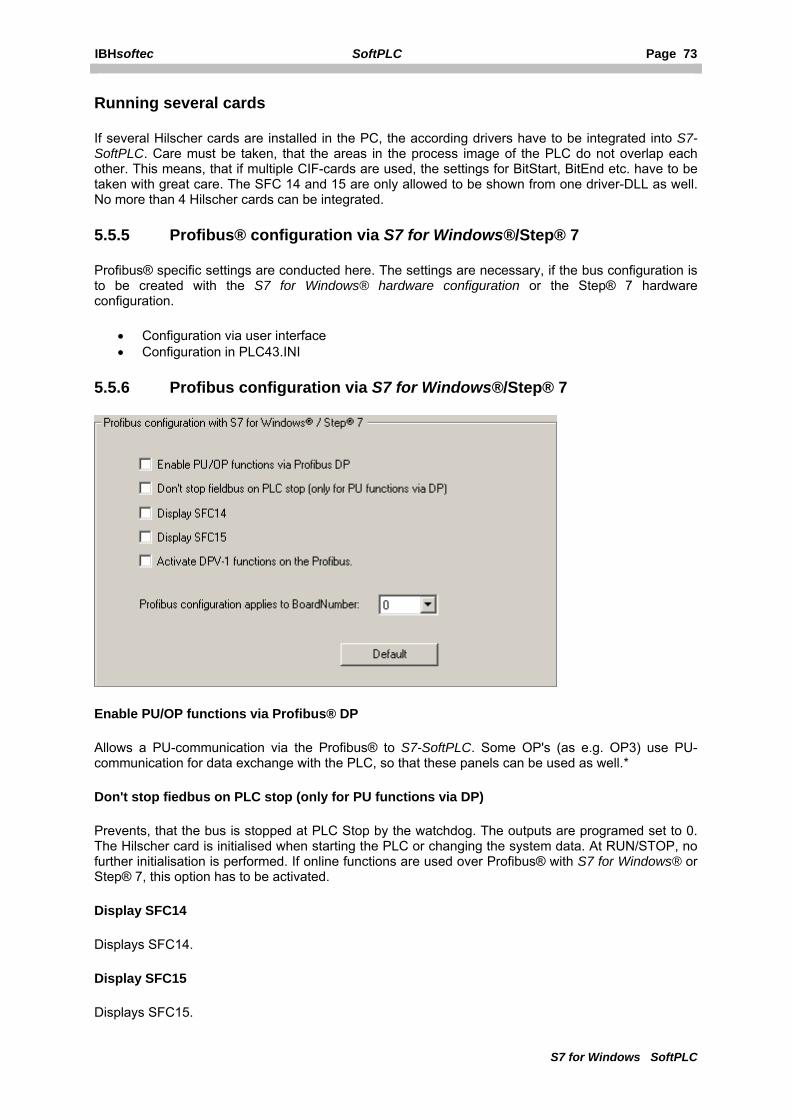
IBHsoftec SoftPLC Page 73
S7 for Windows SoftPLC
Running several cards
If several Hilscher cards are installed in the PC, the according drivers have to be integrated into S7-SoftPLC. Care must be taken, that the areas in the process image of the PLC do not overlap each other. This means, that if multiple CIF-cards are used, the settings for BitStart, BitEnd etc. have to be taken with great care. The SFC 14 and 15 are only allowed to be shown from one driver-DLL as well. No more than 4 Hilscher cards can be integrated.
5.5.5 Profibus® configuration via S7 for Windows®/Step® 7
Profibus® specific settings are conducted here. The settings are necessary, if the bus configuration is to be created with the S7 for Windows® hardware configuration or the Step® 7 hardware configuration.
• Configuration via user interface • Configuration in PLC43.INI
5.5.6 Profibus configuration via S7 for Windows®/Step® 7
Enable PU/OP functions via Profibus® DP
Allows a PU-communication via the Profibus® to S7-SoftPLC. Some OP's (as e.g. OP3) use PU-communication for data exchange with the PLC, so that these panels can be used as well.*
Don't stop fiedbus on PLC stop (only for PU functions via DP)
Prevents, that the bus is stopped at PLC Stop by the watchdog. The outputs are programed set to 0. The Hilscher card is initialised when starting the PLC or changing the system data. At RUN/STOP, no further initialisation is performed. If online functions are used over Profibus® with S7 for Windows® or Step® 7, this option has to be activated.
Display SFC14
Displays SFC14.
Display SFC15
Displays SFC15.

Page 74 SoftPLC IBHsoftec
S7 for Windows SoftPLC
Activate DPV-1 functions on the Profibus
Allows sending and receiving DPV1 functions to DPV1 slaves. SFB52 and SFB53 are available for DPV1 services. *
Profibus® configuration applies to BoardNumber:
The Profibus® configurated system data applies to the CIF card number listed here.
Default
Sets all settings back to their default values.
* The bus configuration has to be created with S7 for Windows® hardware configuration or Step® 7 hardware configuration.
5.5.7 Profibus configuration via S7 for Windows®/Step® 7
In the section [CIFCFG] Profibus® specific settings are conducted. The settings are necessary, if the bus configuration is to be created with the S7 for Windows® hardware configuration or the Step®7 hardware configuration.
Keyname Value range
Default value
Description
BoardNumber 0 .. 3 0 Board number reported by the Hilscher driver
0=Board 0, 1=Board 1 etc. OnlineDP 0 / 1 0 1=Allows a PU-communication via the Profibus® to S7-
SoftPLC. Some OP's (as e.g. OP3) use PU-communication for data exchange with the PLC, so that these panels can be used as well. *
SFC14 0 / 1 0 1=Show SFC14 from this driver
diagnostic capabilities = every slave (detailed diagnostics). *SFC15 0 / 1 0 1=Show SFC14 from this driver
diagnostic capabilities = every slave (detailed diagnostics). *DPV1 0 / 1 0 1=Allows sending and receiving DPV1 functions to DVP1
slaves. SFB52 and SFB53 are available for DPV1 services. *NoStop 0 / 1 0 Prevents, that the bus is stopped at PLC Stop by the
watchdog. The outputs are programed set to 0. At RUN/STOP, no further initialisation is performed. Activating this parameter prevents, that a running PU-connection is disrupted when stopping the PLC. Has to be switched on in CIF30Dn.DLL driver section as well.
* The bus configuration has to be created with S7 for Windows® hardware configuration or Step® 7 hardware configuration.
IBHsoftec SoftPLC Page 75
S7 for Windows SoftPLC
5.6 CP343/CP443 emulation
The settings for the CP343/CP443 emulation are conducted here.
• General • Configuration via user interface • Configuration in PLC43.INI
5.6.1 Configuring CP343/CP443 emulation
The CP functionality of S7-SoftPLC supports the ISO on TCP (RFC 1006; Port 102) protocol for incoming PU connections. Send/Receive functions are supported for the protocols ISO on TCP, TCP/IP and UDP. Via ISO on TCP and TCP/IP Fetch/Write passive is supported as well.
In the hardware configuration of a S7-SoftPLC 416 CP443 with the purchase order number 6GK7 443-1EX11-0XE0 should be chosen , since it supports the TCP/IP protocol only.
The ISO protocol, that is used by 6GK7 443-1EX11-0XE0 for example, would require special ISO network controller drivers. Therefore a connection via ISO protocol can not be established, this is possible via ISO on TCP only. The selection of the network controller of the PU station has to begin with „TCP/IP -> your network controller“.
Operating mode
At the start of S7-SoftPLC a configuration for the CP343/CP443 emulation is searched. The selected blocks for the communication appear in the block list of the PLC.
The following protocols are supported:
Iso-On-TCP PU-channel Iso-On-TCP Send/Receive passive Iso-On-TCP Send/Receive aktive Iso-On-TCP Fetch/Write passive TCP Send/Receive passive TCP Send/Receive aktive TCP Fetch/Write passive UDP Send/Receive
Differences to hardware-PLC
• The local IP-address is taken from the Windows® computer network settings and is not overwritten by system data.
• FC5 and FC50 both behave like FC50 (AG_LSEND) • FC6 and FC60 both behave like FC60 (AG_LRECV) • FC10 only supports the commands NOP, CN_STATUS, CN_STATUS_ALL and
CN_RESET_ALL. • FB55 for configuration via DB must only be called in OB100/OB101.

Page 76 SoftPLC IBHsoftec
S7 for Windows SoftPLC
Modbus on TCP Server
The CP emulation also supports the Modbus on TCP-protocol per default.
The following Modbus functions are supported:
Funktion Datenbereich Erklärung 0x01 Out Read bits 0x02 In Read bits 0x03 Out Read words 0x04 In Read words 0x05 Out Write bit 0x06 Out Write word 0x0F Out Write bits 0x10 Out Write words
The Modbus telegram types, normally accessing the input area, are read from a data block, that can be freely defined by the user.
The Modbus telegram types, normally accessing the output area, are read or written from another data block, that can be freely defined by the user.
That provides the possibility to access the process data of S7-SoftPLC with any HMI or Control Panels, which support the Modbus on TCP-protocol.

IBHsoftec SoftPLC Page 77
S7 for Windows SoftPLC
5.6.2 Configure the CP343/CP443 emulation via user interface
The basic settings of the CP343/CP443 emulation are conducted here.
Start CP343/443 Emulation with the S7-SoftPLC
Starts the CP emulation automatically, if S7-SoftPLC is starting.
Use FB55 (IP_CONFIG)
Shows the FB55 in the block list of S7-SoftPLC.
Use FC5 (AG_SEND)
Shows the FC5 in the block list of S7-SoftPLC.
Use FC6 (AG_RECV)
Shows the FC6 in the block list of S7-SoftPLC.
Use FC7 (AG_LOCK)
Shows the FC7 in the block list of S7-SoftPLC.
Use FC8 (AG_UNLOCK)
Shows the FC8 in the block list of S7-SoftPLC.
Use FC10 (AG_CNTRL)
Shows the FC10 in the block list of S7-SoftPLC.
Use FC50 (AG_LSEND)
Shows the FC50 in the block list of S7-SoftPLC.

Page 78 SoftPLC IBHsoftec
S7 for Windows SoftPLC
Use FC60 (AG_LRECV)
Shows the FC60 in the block list of S7-SoftPLC.
Use FC62 (C_CNTRL)
Shows the FC62 in the block list of S7-SoftPLC.
Send TCP acknowledges (some CPs)
Sends TCP acknowledges.
Start Modbus server
Starts the Modbus Server when starting the CP343/443.
Port
Assigns the defined port to the Modbus Server. A Modbus Server listens to Port 502 per default.
DBIn is Number
Data block number of the In-area.
DBOut is Number
Data block number of the Out-area.
Default
Sets all settings back to their default value.

IBHsoftec SoftPLC Page 79
S7 for Windows SoftPLC
5.6.3 Configuring CP343/443 emulation in PLC43.INI
The basic settings of the CP343/443 emulation are conducted here. S7-SoftPLC expects a section named [CPX43], in which the following keys are being used:
KeyName Defaultwert Beschreibung StartWithPlc 1 Start CP343/443 Emulation with S7-SoftSPS FB55 0 Use FB55 (IP_CONFIG) FC5 0 Use FC5 (AG_SEND) FC6 0 Use FC6 (AG_RECV) FC7 0 Use FC7 (AG_LOCK) FC8 0 Use FC8 (AG_UNLOCK) FC10 0 Use FC10 (AG_CNTRL) FC50 0 Use FC50 (AG_LSEND) FC60 0 Use FC60 (AG_LRECV) FC62 0 Use FC62 (C_CNTRL) SendAcknowledge 0 Send TCP acknowledges (some CPs) ModbusPort 502 Port of the Modbus TCP server
If = 0 Modbus server does not start. ModbusDBIn 501 Data block number of the In-area ModbusDBOut 502 Data block number of the Out-area Example:
Starts the emulation with the PLC and uses FC 50, 60 as well as the Modbus Server.
[CPX43]
StartWithPlc=1
SendAcknowledge=0
FB55=0
FC5=0
FC6=0
FC7=0
FC8=0
FC10=0
FC50=1
FC60=1
FC62=0
ModbusPort=502
ModbusDBIn=501
ModbusDBOut=502

Page 80 SoftPLC IBHsoftec
S7 for Windows SoftPLC
5.7 I/O Port
The computer hardware ports, that should be mapped in the PII/PIQ, are set here.
• Basics • Configuring the I/O Ports via user interface • Configuring the I/O Ports in PLC43.INI
5.7.1 Configuring PC hardware ports
Bytes, words and double words of the process image can be assigned to hardware I/O addresses here. Hardware addresses in the first 64k segment of the PC can be addressed only (ISA-bus). The process image of the inputs is refreshed directly before the OB1 with the values from the input ports. At the end of the OB1 the values of the PIQ are written into the configured output ports. Additionally the peripheral inputs and peripheral outputs can be assigned to ports as well. These are refreshed only, when using these addresses in the PLC-program.
5.7.2 Setting PC hardware port with user interface Configuration
If the I/O configuration is activated, all theoretical possible I/O addresses are searched in the configuration file PLC43.INI of S7-SoftPLC. Because this can take up to 45 seconds, the areas should be limited to the necessary. The outputs can be preset as well with initial values, as with safe values, that are set by the driver at PLC Stop. Bytes, words and double words can be configured. To avoid double assignments the first found entry has priority. If for example an IW4 is found, afterwards there is no search for an IB5, but for an IB6. That applies to double words as well. Overlapping between inputs and peripheral inputs, outputs and peripheral outputs are possible, because inputs and outputs can be, depending on the used hardware, on the same I/O address.
WARNING: PLEASE NOTE, THAT THROUGH FALSE CONFIGURATION, NON-SUITING VALUES CAN BE WRITTEN INTO HARDWARE COMPONENTS. THIS CAN CAUSE DAMAGE TO THE PC HARDWARE. PLEASE NOTE AS WELL, THAT THE HARDWARE PORT ACCESS IS REQUESTED FROM THE OPERATING SYSTEM WHEN STARTING S7-SOFTPLC. THEREFORE THE PORTS HAVE TO BE IN A COHERENT, FREE AREA AND MUST NOT BE IN CONFLICT WITH EXISTING HARDWARE.
IBHsoftec SoftPLC Page 81
S7 for Windows SoftPLC
5.7.3 Setting PC hardware ports with PLC43.INI Installation
The driver DLL IOPORT.DLL must be available in the installation folder of S7-SoftPLC. It has to be entered in the file PLC43.INI, section [OEM], where the drivers of S7-SoftPLC are parameterised.
[OEM]
dll0=ioport.dll
Configuration
If the I/O configuration is activated, all theoretical possible I/O addresses are searched in the configuration file PLC43.INI of S7-SoftPLC. Because this can take up to 45 seconds, the areas should be limited to the necessary. The outputs can be preset as well with initial values, as with safe values, that are set by the driver at PLC Stop. Bytes, words and double words can be configured. To avoid double assignments the first found entry has priority. If for example an IW4 is found, afterwards there is no search for an IB5, but for an IB6. That applies to double words as well. Overlapping between inputs and peripheral inputs, outputs and peripheral outputs are possible, because inputs and outputs can be, depending on the used hardware, on the same I/O address.
Entries
The following section must be contained in the configuration file PLC43.INI:
[ioportdll]
;the following entries are possible (n = consecutive number):
;preset outputs with initial values. Default: 0=No
InitOutputs=0
;set outputs to safe values at Stop. Default: 0=No
SafeOutputs=0
;Outputs only to be written into the hardware when changed. Default: 0=No
BufferOutputs=0
;Limit the area of the entries searched for to reduce scan time.
;area input/output byte from ... Default=0
MinByte=0
;... up to input/output byte. Default=4095
MaxByte=10
;Configuration of the inputs (syntax: start address=I/O Port number):
EBn=Portnumber(Dez)
EWn=Portnumber(Dez)
EDn=Portnumber(Dez)
;Configuration of the peripheral inputs (syntax: start address=I/O Port
number):
PEBn=Portnumber(Dez)

Page 82 SoftPLC IBHsoftec
S7 for Windows SoftPLC
PEWn=Portnumber(Dez)
PEDn=Portnumber(Dez)
;Configuration of the outputs (syntax: output address=I/O Port number):
ABn=Portnumber(Dez)
AWn=Portnumber(Dez)
ADn=Portnumber(Dez)
;initialize I/O Ports with values (at InitOutputs=1)
InitABn=Value(Dez)
InitAWn=Value(Dez)
InitADn=Value(Dez)
;set I/O Ports to safe values at PLC Stop (at SafeOutputs=1)
SafeABn=Value(Dez)
SafeAWn=Value(Dez)
SafeADn=Value(Dez)
;Configuration of peripheral outputs (syntax: peripheral output address=I/O
Port number):
PABn=Portnumber(Dez)
PAWn=Portnumber(Dez)
PADn=Portnumber(Dez)
;initialize I/O Ports with values (at InitOutputs=1)
InitPABn=Value(Dez)
InitPAWn=Value(Dez)
InitPADn=Value(Dez)
;set I/O Ports to safe values at PLC Stop (at SafeOutputs=1)
SafePABn=Value(Dez)
SafePAWn=Value(Dez)
SafePADn=Value(Dez)
WARNING: PLEASE NOTE, THAT THROUGH FALSE CONFIGURATION, NON-SUITING VALUES CAN BE WRITTEN INTO HARDWARE COMPONENTS. THIS CAN CAUSE DAMAGE TO THE PC HARDWARE. PLEASE NOTE AS WELL, THAT THE HARDWARE PORT ACCESS IS REQUESTED FROM THE OPERATING SYSTEM WHEN STARTING S7-SOFTPLC. THEREFORE THE PORTS HAVE TO BE IN A COHERENT, FREE AREA AND MUST NOT BE IN CONFLICT WITH EXISTING HARDWARE.
Example
To demonstrate a possible configuration, the printer port of a PC is mapped to the process image of the PLC. The output port Q (0x378hex = 888dec) is assigned to the QB0, the input port B (0x379hex = 889dec) to the IB0. The output port Q (0x37Ahex = 890dec), from which only five bits are available on the printer port, is assigned to the peripheral input byte PIB10 and the peripheral output byte PQB10. An initialisation is not made.

IBHsoftec SoftPLC Page 83
S7 for Windows SoftPLC
[OEM]
dll0=ioport.dll
[ioportdll]
InitOutputs=0
SafeOutputs=0
BufferOutputs=0
MinByte=0
MaxByte=10
EB0=889
PEB10=890
AB0=888
InitAB0=0
SafeAB0=0
PAB10=890
InitPAB0=0
SafePAB0=0
Changes
If required the source code of this driver is available at our support. Because newer components are normally build on the basis of the PCI bus, these components can not be accessed over this driver. Usually hardware manufacturers deliver drivers and access-DLL's. The source code of the IO-port driver can serve as an example to write an own driver.

Page 84 SoftPLC IBHsoftec
S7 for Windows SoftPLC
5.8 Modbus on TCP
A Modbus on TCP master is configured here, which can cyclically exchange data from I/O modules into the PII/PIQ.
• Calling the Control SFC • Configuring the driver via the user interface • Configuring the driver with PLC43.INI
5.8.1 Modbus on TCP configuration
This driver allows to connect local I/O with the S7-SoftPLC via Ethernet / Modbus on TCP. The driver supports the Modbus on TCP function codes listed in the chart below. If a slave is supposed to run with the S7-SoftPLC, it should be verified, that it supports the listed Modbus functions. If possible the Modbus function Read/Write Registers (0x17) should be used, since it executes reading and writing in one frame. If a slave does not support this funciton, it has to be created as two slaves. The first configuration reads the inputs, the second writes the outputs. Since this isn't very efficient, the function Read/Write should be preferred. Additionally the driver installs a Status SFC/FC, to monitor the status of the Modbus on TCP connection.
Status SFC/FC CALL SFC/FC 193
IN0 := 1 //INPUT INT
RET_VAL := MW 0 //RESULT INT
OUT1 := MW 2 //OUTPUT INT
OUT2 := MD 4 //OUTPUT DWORD
OUT3 := MW 8 //OUTPUT INT
OUT4 := MD 10 //OUTPUT DWORD
Parameter Datentyp Bedeutung
IN0 INT Slave number format: 0,1,2,3,...this corresponds to the slave index number, as configured
RET_VAL INT Returns 0 if a parametrisation does exist.
Otherwise 0x8090
OUT1 INT
Bit 0 = 1 connection established
Bit 1 = 1 Error
Bit 2...7 reserved
Bit 8...15 PLC cycles since last I/O module answer (resetted by Status SFC/FC)
OUT2 DWORD Parametrised IP address OUT3 INT Parametrised port OUT4 DWORD Windows-Error-Code

IBHsoftec SoftPLC Page 85
S7 for Windows SoftPLC
Most important Windows(32-Bit) network-error messages
0x271D / 10013d
Permission denied – Indicates restricted rights or a firewall.
0x2745 / 10053d
Software caused connection abort – Probably defective network connection or no slave available at given address.
0x2746 / 10054d
Connection reset by peer. The slave has disconnected the connection.
0x274C / 10060d
Connection timed out. Timeout on network connection.
0x274D / 10061d
Connection refused. The slave (or a router in-between) has refused the connection.
0x2751 / 10065d
No route to host. The connection to the aimed network can not be established. Network settings and gateway/router settings have to be checked.
Status word
If succeeded the BR of the status word is set, OR, STA and /FC are zero.
If failed the BR, OR, STA and /FC of the status word are zero.

Page 86 SoftPLC IBHsoftec
S7 for Windows SoftPLC
5.8.2 Configuring Modbus on TCP with the user interface
Show Status SFC as FC
Configures whether the Modbus driver installs an FC or a SFC in the block list of S7-SoftPLC.
Status SFC / FC Number
Configures which SFC/FC number is assigned. Care should be taken, that the given number is not already used in the PLC or in the PLC program.
Connect Priority
Sets Connect-Thread priority
Configured Modbus nodes
Configured Modbus devices can be created, configured and removed. The number of parameters, that can be assigned for a Modbus device depends on the used Modbus function.

IBHsoftec SoftPLC Page 87
S7 for Windows SoftPLC
5.8.3 Configuring Modbus on TCP with PLC43.INI Setting the slaves
Syntax for setting the slaves:
01_parameter phrase for the first Modbus slave
02_parameter phrase for the second Modbus slave
...
10_parameter phrase for the tenth and last Modbus slave
The parameter phrases of the slaves must be numbered consecutively, otherwise reading the parameters is stopped at the gap.
Example:
01_IPAdr=192.168.0.80
02_IPAdr=192.168.0.81
06_IPAdr=192.168.0.84
The sequence is stopped at 03_. In this case, only the settings for the slaves from 01_ to 02_ are read.
PLC43.INI parameterisation
The parameterisation fo the PLC43.INI can be conducted manually or with the help of the user inteface.
[OEM]
;Name of I/O driver
DLL0=ilbeth24.dll
[ILBETH24]
;general settings
TypeFC=0 ;create as FC 0= no (SFC), 1 = yes (FC) (default = 0)
StatusSFC=193 ;SFC/FC Number (default = 193)
Prio=251 ;Priority of Connect-Thread (default = 251)
;first Slave
01_IPAdr=192.168.0.21 ;IP address of connection 01
01_Port=502 ;Port of connection 01 (default = 502)
01_ModbusFC=0x17 ;ModbusFunctionCode of connection 01 (default = 0x17)
01_Timeout=2000 ;Timeout of connection in Milliseconds
01_AdrPLC_AW=1 ;output word in process image of the PLC of connection 01
01_AdrI/O_AW=2 ;output word of I/O-module of connection 01
01_Count_AW=1 ;number of output words of connection 01
01_AdrPLC_EW=1 ;input word in process image of the PLC of connection 01

Page 88 SoftPLC IBHsoftec
S7 for Windows SoftPLC
01_AdrI/0_EW=0 ;input word of I/O-module of connection 01
01_Count_EW=1 ;number of output words of connection 01
;second slave
02_IPAdr=192.168.0.22
02_ModbusFC=0x04
02_AdrPLC_EW=0
02_AdrI/O_EW=0
02_Count_EW=10
;third slave
03_IPAdr=192.168.0.23
03_ModbusFC=0x06
03_AdrPLC_AW=10
03_AdrI/O=0
…
The number of parameters, that are to be generated for one slave, depends on the used Modbus function (see chart).
To be able to query the current connection status from the PLC program, the driver installs the SFC 193 (as parameterised in PLC43.INI) into the block list of S7-SoftPLC. This block can be called from the PLC-program, to monitor the hardware status.
IBHsoftec SoftPLC Page 89
S7 for Windows SoftPLC
5.9 NVRAM configuration
Driver to store retain data of S7-SoftPLC. Intended for use with an ADS-TEC PCI-card, a network drive or a hardware simulating a filesystem.
• General and controlling via SFC • Configuration via user interface • Configuration in PLC43.INI
5.9.1 NVRAM configuration
The NVRAM configuration allows a remanent behavior of S7-SoftPLC. The NVRAM configuration builds a file to save the retain data. Depending on the capabilities of your filesystem and the size of the parameterised values, the saving process will take some time, so that the process does not occur in real-time.
It is not possible to store retain data on local hard drives, because Microsoft Windows® writes buffered only and does not store data on the hard drive, because of the high access rates. Thats why the saving of retain data can only be performed on network drives (or similar).
If PC-plug-in cards are being used, that emulate a hard drive via battery buffered RAM, it must be ensured, that the used driver overrides the data buffering of the Microsoft Windows® operating system and that the data is written onto the emulated hard drive immediately.
Remanence checking with STATUS SFC/FC
The STATUS SFC/FC returns two information:
OUT0 (DOWRD) returns the interval of the last saving process.
RET_VAL (INT) see chart:
RET_VAL(INT) Description 0 Everything operational
-1 NVRamDll not longer in memory -2 Unable to open data file -3 No write access -4 Unable to close data file
Calling the STATUS SFC/FC:
CALL SFC 212
OUT0 := MD 0 //OUTPUT DWORD
RET_VAL := MW 4 //RESULT INT
Comment on file systems
It is not possible to store retain data on local hard drives, because Microsoft Windows® writes buffered only and does not store data on the hard drive, because of the high access rates. Thats why the saving of retain data can only be performed on network drives (or similar).
If PC-plug-in cards are being used, that emulate a hard drive via battery buffered RAM, it must be ensured, that the used driver overrides the data buffering of the Microsoft Windows® operating system and that the data is written onto the emulated hard drive immediately.

Page 90 SoftPLC IBHsoftec
S7 for Windows SoftPLC
5.9.2 NVRAM configuration with the user interface
Retain memory type:
Determines whether an ADS-TEC PCI-card or a file system is to be used.
Folder for Retain-File (no local drives):
Path to retain data.
Write inteval (ms):
Sequence, the remanent data is supposed to be saved in.
Priority:
Priority of the thread, that saves the data.
Status SFC Number:
Block number of the Status SFC.
Show Status SFC as FC
Shows Status SFC as FC in S7-SoftPLC.
Remanent areas:
Areas that are being kept remanent.

IBHsoftec SoftPLC Page 91
S7 for Windows SoftPLC
5.9.3 NVRAM configuration with the PLC43.INI
The NVRAM driver allows a remanent behavior of S7-SoftPLC.
The driver creates a file for the retain data. Depending on the capabilities of the used file system and the size of the parameterised values, the saving process will take some time, so that the process does not take place in real-time.
See "comment on file systems" Settings in configuration file PLC43.INI
To activate the driver, the entry DLLn=NVRAMDLL.dll in section [OEM] must be made.
The driver expects the section [IBHNVRAM] where further parameters are defined.
Name of parameters Default value Description RemFolder(required) Full qualified path to retain data WriteInterval(optional) 10 Time interval in milliseconds for the
saving thread WritePrio(optional) THREAD_PRIORITY_IDLE Windows thread priority for the saving
thread ShowFC(optional) 0 Show status block as FC
0 = SFC, 1 = FC. SFCNo(optional) 212 Status block number The sign '#' is a wild-card for a number between 0 an 99 TYP# Remanent type; M=Flag, D=data
block, T=Timer, Z=Counter LEN# Length of data that is kept remanent
starting from address 0 DBNR# Data block number – must be given at
TYP = D only
Example with 1000 flagbytes, 4 counters, 8 timers and 16 bytes from DB10:
[OEM]
dll0=NVRamDll.dll
[IBHNVRAM]
RemFolder=F:\SoftPLC-NVRAM\
TYP0=M
LEN0=1000
TYP1=Z
LEN1=4
TYP2=T
LEN2=8
TYP3=D
LEN3=16
DBNR3=10

Page 92 SoftPLC IBHsoftec
S7 for Windows SoftPLC
5.10 Softnet PN IO
Driver to use Siemens Softnet PN IO from S7-SoftPLC
• General configuration • Configuration via user interface • Configuration with PLC43.INI
5.10.1 Softnet PN IO configuration
To be able to use S7-SoftPLC with PROFINET® IO via SoftNet PN IO 2006, the following steps have to be made.
• SoftNet must be installed and licenced on the computer. • The computer must have a static IP address.
Station Configuration Editor
• In the Station Configuration Editor an application is inserted on index 1.
WARNING: THE STATION NAME MUST BE IDENTICAL WITH THE NAME OF THE COMPUTER.
• On index 3 a component of the type „IE general“ is inserted. In the parameterisation, the network controller for use with PROFINET® has to be selected.
• In the dialog „component properties“ verify the network settings. (The box „Activate ISO protocol only“ must be unchecked.)
Simatic Manager (Step® 7 v5.4 SP1 or better)
• The PG/PC port must be set to TCP/IP. • A SIMATIC PC-station is inserted into the project.
WARNING: THE STATION NAME MUST BE IDENTICAL WITH THE NAME OF THE COMPUTER.
• Start the hardware configuration. • An object is inserted on index 1.
Right-click on index1 >> Insert object >> User application >> Application >> SW V6.3 • An object is inserted on index 3.
Right-click on index 3 >> Insert object >> CP Industrial Ethernet >> IE general >> SW V6.2 SP1...
• In the dialog „Properties – Ethernet port IE general“ the computers static IP must be entered and networked with the new subnet.
• With a right-click on IE general >> Insert PROFINET® I/O system a new PROFINET® network is created.
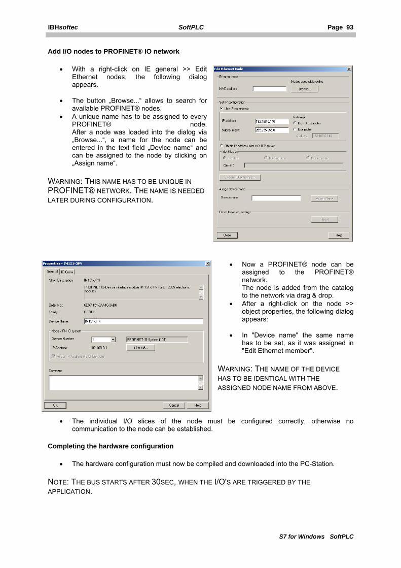
IBHsoftec SoftPLC Page 93
S7 for Windows SoftPLC
Add I/O nodes to PROFINET® IO network
• With a right-click on IE general >> Edit Ethernet nodes, the following dialog appears.
• The button „Browse...“ allows to search for available PROFINET® nodes.
• A unique name has to be assigned to every PROFINET® node. After a node was loaded into the dialog via „Browse...“, a name for the node can be entered in the text field „Device name“ and can be assigned to the node by clicking on „Assign name“.
WARNING: THIS NAME HAS TO BE UNIQUE IN PROFINET® NETWORK. THE NAME IS NEEDED LATER DURING CONFIGURATION.
• Now a PROFINET® node can be assigned to the PROFINET® network. The node is added from the catalog to the network via drag & drop.
• After a right-click on the node >> object properties, the following dialog appears:
• In "Device name" the same name has to be set, as it was assigned in "Edit Ethernet member".
WARNING: THE NAME OF THE DEVICE HAS TO BE IDENTICAL WITH THE ASSIGNED NODE NAME FROM ABOVE.
• The individual I/O slices of the node must be configured correctly, otherwise no communication to the node can be established.
Completing the hardware configuration
• The hardware configuration must now be compiled and downloaded into the PC-Station.
NOTE: THE BUS STARTS AFTER 30SEC, WHEN THE I/O'S ARE TRIGGERED BY THE APPLICATION.

Page 94 SoftPLC IBHsoftec
S7 for Windows SoftPLC
Avoid unnecessary CPU load:
SoftNet PN I/O is a software driver that needs system resources. In order to get the system to high-performance, the following should be noted.
• Close not needed services • Set SIMATIC NET IEPG Help Service to „Deactivated“ from control panel services • Remove the station manager from the StartUp (Start menu)
The service „Simatic Net Station Manager (s7wnsmsk.exe)“ has reserved the port 102 (iso-tsap) for itself, so SoftNet PN IO can not be run in combination with CP343/443 Emulation (Cpx43), because it needs the port 102 as well. If the service "Simatic Net Station Manager (s7wnsmsk.exe)" is deactivated, PROFIBUS® IO will not work anymore.
Typical errors:
• Siemens "Station Configuration Editor" looses the network controller.
Help:
• Start the Station Configuration Editor • Insert the network controller • Close the Station Configuration Editor • Start the Station Configuration Editor again • Remove the network controller (now it knows, that the controller is no longer available) • Insert the network controller again (The controller is ready now) • Close the Station Configuration Editor • Reload the configuration with SIMATIC NCM PC Manager
Using SoftNet PN IO in S7-SoftPLC
SoftNet PN IO can be accessed from the PLC-program via SFC14/15 SFB52/53 only. The parameters LADDR, ID and INDEX do correspond to the PROFINET® address from the hardware configuration.

IBHsoftec SoftPLC Page 95
S7 for Windows SoftPLC
5.10.2 Configuring SoftNet with the user interface
Process data exchange via SFC14/15, Records via SFC52/53
Uses the standard SFC/SFB for data exchange.
Block "Function name" is FC:
Block number of the function "Function name".
Default
Sets all settings back to their default values.

Page 96 SoftPLC IBHsoftec
S7 for Windows SoftPLC
5.10.3 Configuring SoftNet PN IO with PLC43.INI
The driver allows to exchange data from the PLC-program via SFC 14/15 with PROFINET® IO slaves over PROFINET® IO SoftNet®.
Furthermore the SFB 52/53 are available for diagnostic functions as well as reading and writing records to the PROFINET® IO device.
Parameterisation of PnioSn.dll with PLC43.INI
The PnioSn.dll must be integrated in the section [OEM].
[OEM]
dll0=pniosn.dll
Furthermore the PnioSn.dll expects a section [PNIOSN], with the following parameters:
Parameter Default value, possible values Description SlotNumber 3 Port number set in SoftNet TypeFC 0, 1 Use standard SFC/SFB SFC14 14, 1 ... 255 Block DPRD_DAT is FC Nr SFC15 15, 1 ... 255 Block DPWR_DAT is FC Nr SFB52 52, 1 ... 255 Block RDREC is FC Nr SFB53 53, 1 ... 255 Block WRREC is FC Nr
The following example uses the application in the PC-Station on SlotNumber 3, function blocks as FC/FB and uses the FC/FB numbers equivalent to the SFC/SFB numbers:
[PNIOSN]
SlotNumber=3
TypeFC=1
SFC14=14
SFC15=15
SFB52=52
SFB53=53

IBHsoftec SoftPLC Page 97
S7 for Windows SoftPLC
5.11 User SFC
Userdefined SFC's/FC's can be loaded into S7-SoftPLC.
• User SFC's/FC'S basics • Configuration of User SFC's/FC's with the help of the user interface • Configuration of User SFCs/FCs in the PLC43.INI
5.11.1 User SFC configuration
There is the possibility to add user defined SFC's/SFB's to S7-SoftPLC. S7-SoftPLC allows the user to use up to 100 DLLs with user defined system functions (SFC) or functions (FC). Every DLL can contain multiple SFCs or FCs. These SFC/FC can be created by the user in C++, if a certain specification is kept.
By integrating own SFC/FC, the function pool can be expanded by own application specific code parts (technology functions, know-how protection, special hardware components). If the blocks are transferred with the PU to the PLC, the PLC keeps the C++ created internal blocks.
Examples for creating own SFC/FC-DLLs are available at the IBHsoftec support.
5.11.2 Setting the User SFC's/FC's within the user interface

Page 98 SoftPLC IBHsoftec
S7 for Windows SoftPLC
Available SFCs/FCs
The available SFC/FC-DLLs are listed here. SFC/FC-DLLs can be added with the „Search“-button. By activating the „>>“-button, the selected SFC/FC-DLL is moved into the right filed (Selected SFCs/FCs) and therefore added to S7-SoftPLC.
Selected SFCs/FCs
The SFC/FC-DLLs currently assigned to S7-SoftPLC are listed here. By activating the „<<“-button, the selected SFC/FC-DLL is moved into the left field (Available SFCs/FCs) and therefore removed from S7-SoftPLC. The SFC/FC-DLLs can be added to S7-SoftPLC at any time
Search
With the „Search“-button user defined SFC/FC-DLLs can be added to the „Available SFC/FC-DLLs“-field.
Enable I/O Ports with NT4 / Windows 2000 / Windows XP:
If a user SFC/FC accesses a hardware port of the PC directly, it has to be mentioned, that no direct access of the PC hardware is allowed with Windows® NT4, Windows® 2000 and Windows® XP.
To allow direct hardware access, the drivers of S7-SoftPLC can obtain the permission from the operating system.

IBHsoftec SoftPLC Page 99
S7 for Windows SoftPLC
5.11.3 Setting the User SFC's/FC's within the PLC43.INI
In the section [SF] there is the possibility to add user defined SFC's/SFB's to S7-SoftPLC. S7-SoftPLC allows the user to use up to 100 DLLs with user defined system functions (SFC) or functions (FC). Every DLL can contain multiple SFCs or FCs. These SFC/FC can be created by the user in C++, if a certain specification is kept.
By integrating own SFC/FC, the function pool can be expanded by own application specific code parts (technology functions, know-how protection, special hardware components). If the blocks are transferred with the PU to the PLC, the PLC keeps the C++ created internal blocks.
Examples for creating own SFC/FC-DLLs are available at the IBHsoftec support.
Keyname Value area Default value Description SF00 SFCnnn.DLL --- File name of user defined SFC/FC SF01 SFCnnn.DLL --- File name of user defined SFC/FC SF02 SFCnnn.DLL --- File name of user defined SFC/FC .… SF99 SFCnnn.DLL --- File name of user defined SFC/FC
Enable hardware ports
If a user SFC/FC accesses a hardware port of the PC directly, it has to be mentioned, that no direct access of the PC hardware is allowed with Windows® NT4, Windows® 2000 and Windows® XP. To allow direct hardware access, the drivers of S7-SoftPLC can obtain the permission from the operating system. To do so, the section [IO-PORTS] has to be added in the file PLC43.INI.
Below, beginning with the address 0x0378, normally the printer port, 4 ports are enabled for direct port access.
[IO-PORTS]
378=4
For the serial port COM1, normally at address 0x03F8 with a lenght of 8 bytes, the entry would look like this:
[IO-PORTS]
3F8=8
Alternatively the I/O-port driver (ioport.dll) can be used as well.

Page 100 SoftPLC IBHsoftec
S7 for Windows SoftPLC
6 Technical data
This chapter contains the technical data of S7-SoftPLC
• Technical datal • Instruction set • Diagnostic buffer entries • Differences • AppStarter • Zero modem cable
6.1 Technical data Windows NT 4.x/2000/XP
PLC S7 315 PLC S7 416 Load memory 256 kByte adjustable RAM 256 kByte adjustable Blocks 16.384 16.384 Flags (Bit) 16.384 131.072 Timer 256 2048 Counter 256 2048 Digital I/O 1.024 Bit 32.768 Bit Analog I/O 2.048 Byte 8.192 Byte Processing times*) Pentium III 600 MHz 100 µs 100 µs Pentium IV 1,1 GHz 50 µs 50 µs Pentium IV 2,6 GHz 28 µs 28 µs
*) Time setting 50% PLC-time : 50% Windows-time; 1024 mixed instructions (50% binary, 50% digital)

IBHsoftec SoftPLC Page 101
S7 for Windows SoftPLC
6.2 Instruction set
The S7-SoftPLC 315 has the complete instruction set of the Simatic® S7-315 CPU.
The S7-SoftPLC 416 has the complete instruction set of the Simatic® S7-416 CPU.
Bit logic instructions
Instruction Operand Description A AND with a scan to "1" AN AND with a scan to "0" O OR with scan to "1" ON OR with scan to "0" X Exclusive-OR with a scan to "1" XN Exclusive-OR with a scan to "0" I of an input Q of an output M of a memory L of a local data bit T of a timer C of a counter DBX of a data bit DIX of an instant data bit ==0 result equal zero <>0 result unequal zero >0 result greater than zero >=0 result greater or equal zero <0 result less than zero <=0 result less or equal zero UO invalid result OV overflow OS overflow (saving) BR binary result Other boolean logic instructions
Operation Operand Description A( AND left parenthesis AN( AND NOT left parenthesis O( OR left parenthesis ON( OR NOT left parenthesis X( Exclusive OR left parenthesis XN( Exclusive OR NOT left parenthesis ) Right parenthesis O OR-ing AND operations NOT Negate RLO SET Set RLO to "1" CLR Set RLO to "0" SAVE Save RLO to the BR bit

Page 102 SoftPLC IBHsoftec
S7 for Windows SoftPLC
Operation Operand Description = Assign value of RLO S Set R Reset FP Positive edge detection FN Negative edge detection I of an input bit Q of an output bit M of a memory bit L of a local data bit DBX of a data bit DIX of a instance data bit Master Control Relay
Operation Operand Description MCRA Activate MCR MCRD Deactivate MCR MCR( Open MCR zone )MCR Close MCR zone Load / Transfer instructions
Operation Operand Description L Load operand T Transfer operand IB Input byte IW Input word ID Input double word QB Output byte QW Output word QD Pouput double word MB Memory byte MW Memory word MD Memory double word LB Local data byte LW Local data word LD Local data double word DBB Data block byte DBW Data block word DBD Data block double word DIB Instance data block byte DIW Instance data block word DID Instance data block double word STW Status word L Const Load constant value L #Pointer Load pointer L T Timer LC T Timer (BCD coded) L C Counter LC C Counter (BCD coded) L DBNO Data block number L DBLG Data block length L DINO Instance data block number L DILG Instance data block length

IBHsoftec SoftPLC Page 103
S7 for Windows SoftPLC
Peripheral access instructions
Operation Operand Description L PIB Load peripheral input byte L PIW Load peripheral input word L PID Load peripheral input double word T PQB Transfer peripheral output byte T PQW Transfer peripheral output word T PQD Transfer peripheral output double word Accumulator instructions
Operation Operand Description PUSH Push accumulators upwards POP Push accumulators dowwards ENT Push accumulators (without A1) A2->A3, A3->A4 LEAVE Push accumulators (without A1) A4->A3, A3->A2 TAK Change ACCU1 with ACCU2 CAW Change ACCU1 bytes 0 and 1 CAD Change ACCU1 bytes 0 and 3, 1 and 2 Shift and rotating instructions
Operation Operand Description SLW Shift ACCU1-L left (word shift) SLD Shift ACCU1 left (double word shift) SRW Shift ACCU1-L right (word shift) SRD Shift ACCU1 right (double word shift) SSI Shift ACCU1-L right (word shift with sign) SSD Shift ACCU1 right (double word shift with sign) RLD Rotate ACCU1 left (double word) RLDA Rotate ACCU1 left through CC1 RRDA Rotate ACCU1 right through CC1 RRD Rotate ACCU1 right (double word) konst Number of places to shift/rotate - Number of places to shift/rotate located in ACCU2 Timer instructions
Operation Operand Description SP T Start as impulse SE T Start as extendet impulse SD T Start as ON-delay SS T Start as saving ON-delay SF T Start as OFF-delay R T Reset timer FR T Enable timer Counter instructions
Operation Operand Description
CU C Count up (increment) CD C Count down (decrement) S C Set counter R C Reset counter FR C Enable counter
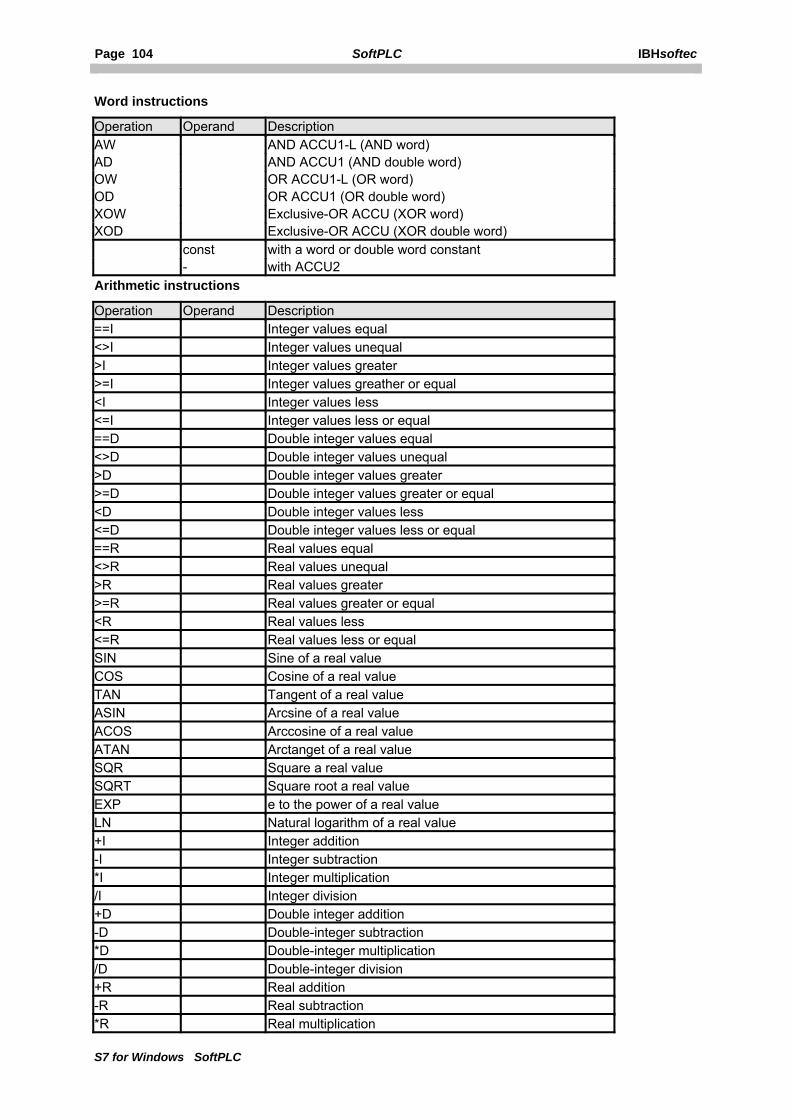
Page 104 SoftPLC IBHsoftec
S7 for Windows SoftPLC
Word instructions
Operation Operand Description AW AND ACCU1-L (AND word) AD AND ACCU1 (AND double word) OW OR ACCU1-L (OR word) OD OR ACCU1 (OR double word) XOW Exclusive-OR ACCU (XOR word) XOD Exclusive-OR ACCU (XOR double word) const with a word or double word constant - with ACCU2 Arithmetic instructions
Operation Operand Description ==I Integer values equal <>I Integer values unequal >I Integer values greater >=I Integer values greather or equal <I Integer values less <=I Integer values less or equal ==D Double integer values equal <>D Double integer values unequal >D Double integer values greater >=D Double integer values greater or equal <D Double integer values less <=D Double integer values less or equal ==R Real values equal <>R Real values unequal >R Real values greater >=R Real values greater or equal <R Real values less <=R Real values less or equal SIN Sine of a real value COS Cosine of a real value TAN Tangent of a real value ASIN Arcsine of a real value ACOS Arccosine of a real value ATAN Arctanget of a real value SQR Square a real value SQRT Square root a real value EXP e to the power of a real value LN Natural logarithm of a real value +I Integer addition -I Integer subtraction *I Integer multiplication /I Integer division +D Double integer addition -D Double-integer subtraction *D Double-integer multiplication /D Double-integer division +R Real addition -R Real subtraction *R Real multiplication

IBHsoftec SoftPLC Page 105
S7 for Windows SoftPLC
/R Real division MOD Double integer dicision (modulo) + const Add a constant +P# const Add a pointer DEC dekrement ACCU1-LL (one byte) INC inkrement ACCU1-LL (one byte) Data type conversion instructions
Operation Operand Description ITD Convert integer to double integer ITB Convert integer to BCD DTB Convert double integer to BCD DTR Convert double integer to real BTI Convert BCD to integer BTD Convert BCD to double integer RND Convert real to double integer (round) RND+ Convert real to double integer (round up) RND- Convert real to double integer (round down) TRUNC Convert reeal to double integer (truncate) INVI Invert ACCU1-L (integer) INVD Invert ACCU1 (double integer) NEGI Negate ACCU1-L (integer) NEGD Negate ACCU1 (double integer) NEGR Negate ACCU1 (real) ABS Absolute value (real) Jump instructions
Operation Operand Description JU Ziel Jump unconditional JC Ziel Jump if RLO = 1 JCB Ziel Jump if RLO = 1 (save RLO) JCN Ziel Jump if RLO = 0 JNB Ziel Jump if RLO = 0 (save RLO) JBI Ziel Jump if BR = 1 JNBI Ziel Jump if BR = 0 JZ Ziel Jump if compare result = 0 JN Ziel Jump if compare result ≠ 0 JP Ziel Jump if compare result > 0 JPZ Ziel Jump if compare result >= 0 JM Ziel Jump if compare result < 0 JMZ Ziel Jump if compare result <= 0 JUO Ziel Jump if compare result "Unordered Math Instruction" JO Ziel Jump on overflow JOS Ziel Jump on saving overflow JL Ziel Jump distributor LOOP Ziel Loop programming (decrement ACCU1-L and jump if ≠ 0

Page 106 SoftPLC IBHsoftec
S7 for Windows SoftPLC
Block call instructions
Operation Operand Funktionsbeschreibung CALL FB Unconditional call of an FB with parameter transfer CALL FC Unconditional call of an FC with parameter transfer CALL SFB Unconditional call of an SFB with parameter transfer CALL SFC Unconditional call of an SFC with parameter transfer UC FB Unconditional call of an FB without parameter transfer CC FB Conditional call of an FB without parameter transfer UC FC Unconditional call of an FC without parameter transfer CC FC Conditional call of an FC without parameter transfer BEU End block unconditionally BEC End block conditionally (RLO = 1) BE End block OPN DB Open data block DI Open instance data block TDB Exchange data block registers Indirect adressing instructions
Operation Operand Description LAR1/LAR2 Load AR1/AR2 MD
LD
DBD
DID
with memory double word
with local data double word
with datablock double word
with instance data block double word LAR1 - Load AR1 with ACCU1 LAR2 - Laod AR2 with ACCU1 LAR1 AR2 Load AR1 with AR2 LAR1 P# Load AR1 with pointer LAR2 P# Load AR2 with pointer
Transfer in AR1/AR2 TAR1/TAR2 MD
LD
DBD
DID
in memory double word
in local data double word
in datablock double word
in instance data block double word TAR1 - Transfer AR1 in ACCU1 TAR2 - Transfer AR2 in ACCU1 TAR1 AR2 Transfer AR1 in AR2 TAR Swap AR1 with AR2 +AR1 Add ACCU1 to AR1 +AR2 Add ACCU1 to AR2 +AR1 P# Add pointer to AR1 +AR2 P# Add pointer to AR2
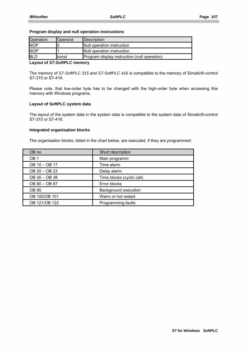
IBHsoftec SoftPLC Page 107
S7 for Windows SoftPLC
Program display and null operation instructions
Operation Operand Description NOP 0 Null operation instruction NOP 1 Null operation instruction BLD konst Program display instruction (null operation) Layout of S7-SoftPLC memory
The memory of S7-SoftPLC 315 and S7-SoftPLC 416 is compatible to the memory of Simatic®-control S7-315 or S7-416.
Please note, that low-order byte has to be changed with the high-order byte when accessing this memory with Windows programs.
Layout of SoftPLC system data
The layout of the system data in the system data is compatible to the system data of Simatic®-control S7-315 or S7-416.
Integrated organisation blocks
The organisation blocks, listed in the chart below, are executed, if they are programmed:
OB no Short description OB 1 Main programm OB 10 – OB 17 Time alarm OB 20 – OB 23 Delay alarm OB 30 – OB 38 Time blocks (cyclic call) OB 80 – OB 87 Error blocks OB 90 Background execution OB 100/OB 101 Warm or hot restart OB 121/OB 122 Programming faults
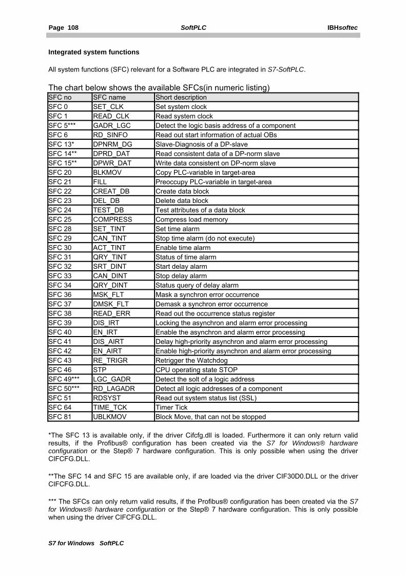
Page 108 SoftPLC IBHsoftec
S7 for Windows SoftPLC
Integrated system functions
All system functions (SFC) relevant for a Software PLC are integrated in S7-SoftPLC.
The chart below shows the available SFCs(in numeric listing) SFC no SFC name Short description SFC 0 SET_CLK Set system clock SFC 1 READ_CLK Read system clock SFC 5*** GADR_LGC Detect the logic basis address of a component SFC 6 RD_SINFO Read out start information of actual OBs SFC 13* DPNRM_DG Slave-Diagnosis of a DP-slave SFC 14** DPRD_DAT Read consistent data of a DP-norm slave SFC 15** DPWR_DAT Write data consistent on DP-norm slave SFC 20 BLKMOV Copy PLC-variable in target-area SFC 21 FILL Preoccupy PLC-variable in target-area SFC 22 CREAT_DB Create data block SFC 23 DEL_DB Delete data block SFC 24 TEST_DB Test attributes of a data block SFC 25 COMPRESS Compress load memory SFC 28 SET_TINT Set time alarm SFC 29 CAN_TINT Stop time alarm (do not execute) SFC 30 ACT_TINT Enable time alarm SFC 31 QRY_TINT Status of time alarm SFC 32 SRT_DINT Start delay alarm SFC 33 CAN_DINT Stop delay alarm SFC 34 QRY_DINT Status query of delay alarm SFC 36 MSK_FLT Mask a synchron error occurrence SFC 37 DMSK_FLT Demask a synchron error occurrence SFC 38 READ_ERR Read out the occurrence status register SFC 39 DIS_IRT Locking the asynchron and alarm error processing SFC 40 EN_IRT Enable the asynchron and alarm error processing SFC 41 DIS_AIRT Delay high-priority asynchron and alarm error processing SFC 42 EN_AIRT Enable high-priority asynchron and alarm error processing SFC 43 RE_TRIGR Retrigger the Watchdog SFC 46 STP CPU operating state STOP SFC 49*** LGC_GADR Detect the solt of a logic address SFC 50*** RD_LAGADR Detect all logic addresses of a component SFC 51 RDSYST Read out system status list (SSL) SFC 64 TIME_TCK Timer Tick SFC 81 UBLKMOV Block Move, that can not be stopped
*The SFC 13 is available only, if the driver Cifcfg.dll is loaded. Furthermore it can only return valid results, if the Profibus® configuration has been created via the S7 for Windows® hardware configuration or the Step® 7 hardware configuration. This is only possible when using the driver CIFCFG.DLL.
**The SFC 14 and SFC 15 are available only, if are loaded via the driver CIF30D0.DLL or the driver CIFCFG.DLL.
*** The SFCs can only return valid results, if the Profibus® configuration has been created via the S7 for Windows® hardware configuration or the Step® 7 hardware configuration. This is only possible when using the driver CIFCFG.DLL.

IBHsoftec SoftPLC Page 109
S7 for Windows SoftPLC
Integrated system blocks
The system blocks (SFB) relevant for a software PLC are integrated in S7-SoftPLC.
The following system function blocks are supported: SFB no SFB name Short description SFB 0 CTU Count up SFB 1 CTD Count down SFB 2 CTUD Count up and down SFB 3 TP Generate pulse SFB 4 TON Generate ON-delay SFB 5 TOF Generate OFF-delay SFB 32 DRUM Implement sequencer SFB 52**** RDREC_DP Read data record SFB 53**** WRREC_DP Write data record
****The SFB 52 and SFB 53 are only available if the driver CIFCFG.DLL is loaded and the entry DPV1=1 is set.
6.3 Diagnostic buffer entries
The chart below shows the differences to S7-hardware PLC diagnostic buffer entries:
Diagnostic buffer entries Driver Description
0xA000 CIF PROFIBUS® CIF-PROFIBUS®-card could not be initialized. 0xA001 CIF PROFIBUS® Timeout during warm start. 0xA002 CIF PROFIBUS® Parameter inappropriate for CIF-Task 0xA003 CIF PROFIBUS® Timeout during hot start 0xA004 CIF PROFIBUS® Error when reading CIF-Firmware info 0xA005 CIF PROFIBUS® Error when reading CIF-driver status 0xA006 CIF PROFIBUS® Error when writing a message into the CIF-card 0xA007 CIF PROFIBUS® Error when writing a message from the CIF-card 0xA008 CIF PROFIBUS® Error at PROFIBUS® Diagnostics (PU) CIF-error code
0xA009 CIF PROFIBUS® Error at PROFIBUS® Diagnostics (SFC/SFB) CIF-error code
0xA010 CIF PROFIBUS® No CIF-driver installed 0xA011 CIF PROFIBUS® CIF-PROFIBUS®-card could not be initialized 0xA012 CIF PROFIBUS® CIF-PROFIBUS®-card not available 0xA013 CIF PROFIBUS® Bus parameters for slaves could not be set
0xA014 CIF PROFIBUS® Parameterisation of the CIF-PROFIBUS®-card with SDB-Daten failed
0xA015 MPI® MPI®-telegramm error 0xA016 CIF PROFIBUS® Error in PU communication via PROFIBUS® 0xA017 CIF PROFIBUS® Error in PU communication via PROFIBUS® 0xA018 CIF PROFIBUS® Error in PU communication via PROFIBUS®
0xA019 CIF PROFIBUS® Timeout in input data exchange with the CIF-card during SFC DPRD_DAT
0xA020 CIF PROFIBUS® Error in input data exchange with the CIF-card during SFC DPRD_DAT

Page 110 SoftPLC IBHsoftec
S7 for Windows SoftPLC
0xA021 CIF PROFIBUS® Timeout in output data exchange with the CIF-card during SFC DPWR_DAT
0xA022 CIF PROFIBUS® Error in output data exchange with the CIF-card during SFC DPWR_DAT
0xA023 CIF PROFIBUS® CIF-PROFIBUS®-card could not be detected 0xA024 CIF PROFIBUS® CIF-PROFIBUS®-card could not be initialized 0xA025 MPI® MPI®-telegramm error 0xA050 CIF 30/50/60 No CIF-driver installed 0xA051 CIF 30/50/60 CIF-card could not be initialized 0xA052 CIF 30/50/60 CIF-card not available 0xA053 CIF 30/50/60 Timeout during warm start
0xA054 CIF 30/50/60 Application could not be set to operational mode "READY"
0xA055 CIF 30/50/60 Error in I/O-data exchange with the CIF-card during PII/PIQ update
0xA056 CIF 30/50/60 Error in input data exchange with the CIF-card during T PI
0xA057 CIF 30/50/60 Error in output data exchange with the CIF-card during T PQ
0xA058 CIF 30/50/60 Error reading CIF-Task-mode 0xA060 CIF 30/50/60 Error reading CIF-Task-mode 0xA061 CIF 30/50/60 Error accessing the watchdog 0xA062 CIF 30/50/60 CIF-driver not in operational mode "COM" 0xA064 CIF 30/50/60 Error reading CIF-driver status 0xA065 CIF 30/50/60 Error reading CIF-driver status
0xA069 CIF 30/50/60 Timeout in I/O-data exchange with the CIF-card during PII/PIQ update
0xA070 CIF 30/50/60 Timeout in input data exchange with the CIF-card during L PI
0xA071 CIF 30/50/60 Timeout in output data exchange with the CIF-card during T PQ
0xA072 CIF 30/50/60 Timeout in input data exchange with the CIF-card during SFC DPRD_DAT
0xA073 CIF 30/50/60 Error in input data exchange with the CIF-card during SFC DPWR_DAT
0xA074 CIF 30/50/60 Timeout in input data exchange with the CIF-card during SFC DPRD_DAT
0xA075 CIF 30/50/60 Error in output data exchange with the CIF-card 0xA080 CIF 30/50/60 CIF-driver not ready 0xA081 CIF 30/50/60 CIF-driver not in mode "RUN" 0xA082 CIF 30/50/60 CIF-driver not in mode "COM"
0xA100 TwinCAT I/O Port number from PLC43.INI, not available in TwinCAT task Subsequent value is returned from TCatIoOpen
0xA101 TwinCAT I/O Error in PLC43.INI Periphery start < byte start
0xA102 TwinCAT I/O PII/PIQ update failed
0xA103 TwinCAT I/O Error in PLC43.INI Periphery < process image
0xA104 TwinCAT I/O Timeout when connecting to TwinCAT driver Subsequent value is returned from the last function

IBHsoftec SoftPLC Page 111
S7 for Windows SoftPLC
0xA105 TwinCAT I/O TwinCAT driver not in RUN Subsequent value is returned from the function TCatGetState()
0xA106 TwinCAT I/O
TwinCAT driver update ClearOutputs failed (driver not in RUN anymore) Subsequent value is returned from the function TCatIoOutputUpdate
0xA107 TwinCAT I/O
TwinCAT driver update PII failed (driver not in RUN anymore) Subsequent value is retured from the function TCatIoInputUpdate
0xA108 TwinCAT I/O
TwinCAT driver update PIQ failed (driver not in RUN anymore) Subsequent value is returned from the function TCatIoOutputUpdate
0xA109 TwinCAT I/O
TwinCAT driver update LoadPI failed (driver not in RUN anymore) Subsequent value is returned from the function TCatIoInputUpdate
0xA110 TwinCAT I/O
TwinCAT driver update StorePQ failed (driver not in RUN anymore) Subsequent value is returned from the function TCatIoOutputUpdate
0xA111 TwinCAT I/O TCatIoGetInputPtr failed 0xA112 TwinCAT I/O TCatIoGetOutputPtr failed
0xA113 TwinCAT I/O
ADS communication thread could not get local address and was closed; No ADS communication possible Next value is returned from the function __AdsGetLocalAddress,if value is 0, then __AdsPortOpen has failed
0xA120 Softnet PN IO Softnet error code of function PNIO_set_mode followed by the Softnet error code
0xA121 Softnet PN IO Softnet error code of function PNIO_controller_open followed by Index of controller, then Softnet error code
0xA122 Softnet PN IO Callback-error code for "mode change confirmation" followed by the Softnet error code
0xA123 Softnet PN IO Callback-error code for "device activate confirmation" followed by the Softnet error code
0xA124 Softnet PN IO Softnet error code of function PNIO_close followed by the Softnet error code
0xA126 Softnet PN IO Error in initialising of the Softnet PN IO driver
0xA127 Softnet PN IO Softnet error code of function PNIO_set_mode operate followed by the Softnet error code
0xA128 Softnet PN IO Driver needs too much time to get into operate mode during initialization
0xA140 ADDI-DATA Addidata error code Subsequent value is returned from an ADDIPACK function
0xA200 I/O Port No I/O Port access permitted by OS

Page 112 SoftPLC IBHsoftec
S7 for Windows SoftPLC
6.4 Differences between S7-SoftPLC and Hardware-PLC
In contrast to a conventional hardware-based control S7-SoftPLC does not have own hardware. It always has to be integrated in an existing computer system with a Windows® operating system.
Since S7-SoftPLC runs within a Windows® operating system, other Windows® applications such as EXCEL® or ACCESS® can access PLC-operands directly and fast without hardware wiring.
In contrast to a hardware-PLC the size of S7-SoftPLC 416 load memory can be changed flexibly (up to the maximum available memory size of the PC).
Differences between S7-SoftPLC 315 and S7-SoftPLC 416
The difference between S7-SoftPLC 315 and S7-SoftPLC 416 is a different number of flags, timers and counters according to the hardware-PLC.
The differences comply to the differences between the Siemens hardware PLC 315 and 416. The load memory of S7-SoftPLC 315 ist limited to 256 kByte, while the load memory of S7-SoftPLC 416 can be configured freely.
Non available features in S7-SoftPLC
Since there are physical differences between a hardware-PLC and a Windows computer, it is not possible to implement every feature of the CPU S7-315 resp. CPU S7-416 in S7-SoftPLC. However, existing programs should be executable on S7-SoftPLC with small changes.
The following organisation blocks are not supported:
• OB 60: multiple processor alarm • OB 40 – OB 47: processor alarm 0 - 7
Time OBs are not terminated by Windows®, which means those OBs are not allowed to have long cycle times(<1ms).
Furthermore SFBs and SFCs, that do not make sense on a PC platform, are not implemented. There is the possibility to extend S7-SoftPLC with user defined SFC's written in C++.
Diagnostic buffer
In addition to normal diagnostic buffer entries, which are recorded within the diagnostic buffer while starting or in the event of programming errors, area transgressions or missing modules, there are additional entries.
Those are created by the hardware-drivers of S7-SoftPLC and giving exact informations about the cause of an eventually occurred problem. Before contacting our support, please save an extract of the diagnostic buffer by using the programming unit. This way an eventual problem can be located easily.

IBHsoftec SoftPLC Page 113
S7 for Windows SoftPLC
Starting S7-SoftPLC as service
In order to prevent accesses of non privileged users, PLC can be started as service. For this purpose S7-SoftPLC must be enlisted in the service list. Therefore open the command line and go to the installation folder of S7-SoftPLC.
Enter the following command in the command line interface:
C:\SoftSPS>plc416.exe –Service
An error message must not appear. S7-SoftPLC is now enlisted in the service list. Via "Control panel - Management - Services" the service "CPUS7" can now be found in the list. The start up can be set to "automatic", so that S7-SoftPLC starts without an user logged in on the computer. It is also possible, that user accounts with limited rights can use S7-SoftPLC.
Delete S7-SoftPLC from the "Control panel - Management - Services", that it can be executed as normal application
C:\SoftSPS>plc416.exe –RegServer
NOTE: ADMINISTRATIVE RIGHTS ARE REQUIRED
UPS operation
The most UPS programs provide the possibility to have certain operations executed before shutting down the PC. In most cases programs or batch files to be executed before the shut-down can be configured.
If the application "PlcStop.exe"(in the S7-SoftPLC installation directory) is configured here, the PLC saves the program and S7-SoftPLC is closed correctly thereafter.
Unauthorised accesses
In order to prevent unauthorized access to the computer, S7-SoftPLC can of course not provide any security mechanisms.
Appropriate actions, customized to the application, have to be taken by the user.
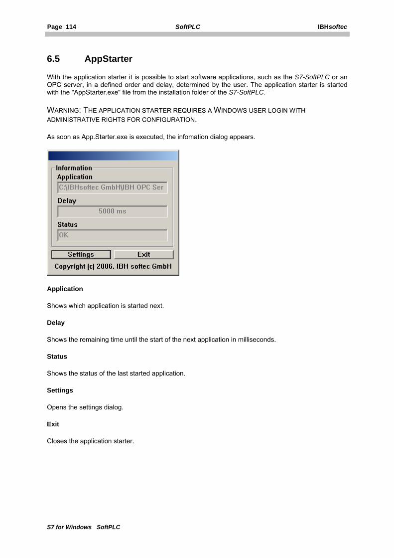
Page 114 SoftPLC IBHsoftec
S7 for Windows SoftPLC
6.5 AppStarter
With the application starter it is possible to start software applications, such as the S7-SoftPLC or an OPC server, in a defined order and delay, determined by the user. The application starter is started with the "AppStarter.exe" file from the installation folder of the S7-SoftPLC.
WARNING: THE APPLICATION STARTER REQUIRES A WINDOWS USER LOGIN WITH ADMINISTRATIVE RIGHTS FOR CONFIGURATION.
As soon as App.Starter.exe is executed, the infomation dialog appears.
Application
Shows which application is started next.
Delay
Shows the remaining time until the start of the next application in milliseconds.
Status
Shows the status of the last started application.
Settings
Opens the settings dialog.
Exit
Closes the application starter.

IBHsoftec SoftPLC Page 115
S7 for Windows SoftPLC
Setting up AppStarter
The application starter is configured in the setting dialog.
Launch sequence
The "Launch sequence" lists the sequence of applications to be started. The applications are started, beginning from top, in the sequence as shown.
Delay [ms]
Time in milliseconds until the start of the application. The time until the start of the first application elapses, as soon as the application starter is started. The time until the start of the next application elapses, as soon as the previous application is started.
Full qualified application path
Full qualified path and file, that is to be executed, in order to start the application.
...
Browsing function for the file, that is to be executed.
OK
Adopts the settings and closes the setting dialog.

Page 116 SoftPLC IBHsoftec
S7 for Windows SoftPLC
Cancel
Discards the changes and closes the setting dialog.
NOTE: "REGISTER IN AUTOSTART“ AND "REMOVE FROM AUTOSTART“ IS PERFORMED DIRECTLY AND INDEPENDENTLY OF OK/CANCEL.
Register in Autostart
The settings are saved in the Windows® registry. After starting Windows, the application starter and therefore the listed applications are started.
Remove from Autostart
The auto start settings are removed from the Windows® registry. The application starter is not automatically executed.
Windows® registry entry:
HKEY_LOCAL_MACHINE\SOFTWARE\Microsoft\Windows\CurrentVersion\Run
6.6 Zero modem cable Sub.-D case Sub.-D case Connector Connector
9 Pin 25 Pin 9 Pin 25 Pin 1 ----- -------- no connection ------- 1 ----- 2 3 ------------------------------------ 3 2 3 2 ------------------------------------ 2 3 4 20 ------------------------------------ 6 6 5 7 ------------------------------------ 5 7 6 6 ------------------------------------ 4 20 7 4 ------------------------------------ 8 5 8 5 ------------------------------------ 7 4 9 ----- -------- no connection ------- 9 -----
housing housing ------------- shield ------------- housing housing