s280-77-1: form 4c recloser control - cooper industries s280-77-4 form 4c recloser control ... both...
TRANSCRIPT

Safety Information . . . . . . . . . . . . . . . . . . . . . . . . . . 2Product Information . . . . . . . . . . . . . . . . . . . . . . . . . 3
Introduction . . . . . . . . . . . . . . . . . . . . . . . . . . . . . . 3ANSI Standards . . . . . . . . . . . . . . . . . . . . . . . . . . . 3Quality Standards . . . . . . . . . . . . . . . . . . . . . . . . . 3Acceptance and Initial Inspection . . . . . . . . . . . . . 3Handling and Storage . . . . . . . . . . . . . . . . . . . . . . 3Control Battery Storage and Charging . . . . . . . . . . 3Control Power . . . . . . . . . . . . . . . . . . . . . . . . . . . . 4Initializing the Control . . . . . . . . . . . . . . . . . . . . . . 4
Description Of Control . . . . . . . . . . . . . . . . . . . . . . . 5Control Operation . . . . . . . . . . . . . . . . . . . . . . . . . 5Control Front Panel . . . . . . . . . . . . . . . . . . . . . . . . 6Keyboard and LCD Display . . . . . . . . . . . . . . . . . . 6Control Panel LCD Indicators . . . . . . . . . . . . . . . . 7Data Port on Control Front Panel . . . . . . . . . . . . . 7Manual Operating Controls . . . . . . . . . . . . . . . . . . 8Battery Meter and Test Panel . . . . . . . . . . . . . . . . . 9Battery Test Procedure . . . . . . . . . . . . . . . . . . . . . 9Battery Charger Operation . . . . . . . . . . . . . . . . . . . 9Battery Charging with Portable Charger . . . . . . . . 10Battery Reference Information . . . . . . . . . . . . . . . . 10Initial Programming Prior to Installation . . . . . . . . . 10Control Security . . . . . . . . . . . . . . . . . . . . . . . . . . . 10Control Back Panel . . . . . . . . . . . . . . . . . . . . . . . . 11Keyboard Functions . . . . . . . . . . . . . . . . . . . . . . . . 12Interpreting the LCD Displays . . . . . . . . . . . . . . . . 13
Installation Procedure . . . . . . . . . . . . . . . . . . . . . . . 14Control/Recloser Compatibility . . . . . . . . . . . . . . . 14Mounting the Control . . . . . . . . . . . . . . . . . . . . . . . 14Control Cable . . . . . . . . . . . . . . . . . . . . . . . . . . . . . 14Grounding the Control . . . . . . . . . . . . . . . . . . . . . . 15Customer Connections for AC Power . . . . . . . . . . 19Customer Connections for Remote andSupervisory Operation . . . . . . . . . . . . . . . . . . . . . . 19Shielding and Surge Protection ofSupervisory Cables . . . . . . . . . . . . . . . . . . . . . . . . 19
Standard Universal I/O Board . . . . . . . . . . . . . . . . . 23Customer Options For The Block of Close Feature . . 24Alternate Minimum Trip Operation . . . . . . . . . . . . . 25Non-Reclosing Operation . . . . . . . . . . . . . . . . . . . . 26Ground Trip Block Operation . . . . . . . . . . . . . . . . . 27Accessories . . . . . . . . . . . . . . . . . . . . . . . . . . . . . . . 28
Optional Universal I/O Board . . . . . . . . . . . . . . . . . 28Hot Line Tag . . . . . . . . . . . . . . . . . . . . . . . . . . . . . . 30Trip On TCC2 . . . . . . . . . . . . . . . . . . . . . . . . . . . . . 32Sensitive Ground/Earth Fault . . . . . . . . . . . . . . . . . 33Switch Mode . . . . . . . . . . . . . . . . . . . . . . . . . . . . . 34
Before Placing Control and Recloser Into Service . . . 35Testing and Troubleshooting . . . . . . . . . . . . . . . . . 36Maintenance Information . . . . . . . . . . . . . . . . . . . . . 47Removal Of Control Front Panel Assembly . . . . . . 48Event Recorder Data Record Sheet . . . . . . . . . . . . 50
1
ReclosersKyle Form 4C Microprocessor-Based RecloserControl Installation and Operation Instructions
Service Information
June 2004 • Supersedes 6/02Printed in USA
Contents
Figure 1. 961066KM
Kyle® Form 4C Microprocessor-Based Recloser Control.
S280-77-1For Serial Number 232001 and above

2
Kyle Form 4C Microprocessor-Based Recloser Control Description, Installation and Operation Instructions
The instructions in this manual are not intended as asubstitute for proper training or adequate experience inthe safe operation of the equipment described. Onlycompetent technicians who are familiar with this equip-ment should install, operate, and service it.
A competent technician has these qualifications:
• Is thoroughly familiar with these instructions.
• Is trained in industry-accepted high- and low-voltagesafe operating practices and procedures.
• Is trained and authorized to energize, de-energize,clear, and ground power distribution equipment.
• Is trained in the care and use of protective equip-ment such as flash clothing, safety glasses, faceshield, hard hat, rubber gloves, hotstick, etc.
Following is important safety information. For safe instal-lation and operation of this equipment, be sure to readand understand all cautions and warnings.
Safety InstructionsFollowing are general caution and warning statementsthat apply to this equipment. Additional statements,related to specific tasks and procedures, are locatedthroughout the manual.
SAFETY INFORMATION
SAFETY FOR LIFECooper Power Systems products meet or exceed all applicable industry standards relating to product safety. We activelypromote safe practices in the use and maintenance of our products through our service literature, instructional trainingprograms, and the continuous efforts of all Cooper Power Systems employees involved in product design, manufacture,marketing, and service.
We strongly urge that you always follow all locally approved safety procedures and safety instructions when workingaround high voltage lines and equipment and support our “Safety For Life” mission.
!SAFETYFOR LIFE
!SAFETYFOR LIFE
WARNING: This equipment is not intended toprotect human life. Follow all locally approved
procedures and safety practices when installing oroperating this equipment. Failure to comply can result indeath, severe personal injury and equipment damage.
G102.1
!
DANGER: Hazardous voltage. Contact withhazardous voltage will cause death or severe
personal injury. Follow all locally approved safety pro-cedures when working around high- and low-voltagelines and equipment. G103.3
!
WARNING: Before installing, operating, main-taining, or testing this equipment, carefully read
and understand the contents of this manual. Improperoperation, handling or maintenance can result in death,severe personal injury, and equipment damage. G101.0
!
WARNING: Power distribution equipment mustbe properly selected for the intended application.
It must be installed and serviced by competent person-nel who have been trained and understand proper safe-ty procedures. These instructions are written for suchpersonnel and are not a substitute for adequate trainingand experience in safety procedures. Failure to proper-ly select, install, or maintain power distribution equip-ment can result in death, severe personal injury, andequipment damage. G122.2
!
This manual may contain four types of hazardstatements:
DANGER: Indicates an imminently haz-ardous situation which, if not avoided, will
result in death or serious injury.
WARNING: Indicates a potentially haz-ardous situation which, if not avoided, could
result in death or serious injury.
CAUTION: Indicates a potentially hazardoussituation which, if not avoided, may result in
minor or moderate injury.
CAUTION: Indicates a potentially hazardous situ-ation which, if not avoided, may result in equip-ment damage only.
!
!
Hazard Statement Definitions
!

IntroductionService Information S280-77-1 provides installation andoperating instructions for the Kyle® Form 4C micro-processor-based recloser control. Refer to Service Infor-mation S280-77-4 Form 4C Recloser ControlProgramming Guide for additional information.
Read this Manual FirstRead and understand the contents of this manual andfollow all locally approved procedures and safety prac-tices before installing or operating this equipment.
Additional InformationThese instructions cannot cover all details or variations inthe equipment, procedures, or process described, nor toprovide directions for meeting every possible contingencyduring installation, operation, or maintenance. For addi-tional information, contact your Cooper Power Systemsrepresentative.
ANSI StandardsKyle® reclosers are designed and tested in accordancewith the following ANSI Standards: C37.60 and C37.85and ANSI Guide C37.61.
Quality StandardsISO 9001:2000 Certified Quality Management System
Acceptance and InitialInspectionEach Form 4C control is completely assembled, tested,and inspected at the factory. It is carefully calibrated,adjusted and in good condition when accepted by thecarrier for shipment.
Upon receipt, inspect the carton for signs of damage.Unpack the control and inspect it thoroughly for damageincurred during shipment. If damage is discovered, file aclaim with the carrier immediately.
Handling and StorageBe careful during handling and storage of the control tominimize the possibility of damage. If the control is tobe stored for any length of time prior to installation, pro-vide a clean, dry storage area. If storage is in a humidatmosphere, make provisions to keep the control circuit-ry energized.
Note: To energize the control, apply ac power to the ac sup-ply input terminal block located in the lower right handcorner of the back panel of the control cabinet. Referto the Customer Connection for AC Power section inthis manual.
Control Battery Storage andChargingTemperature has an effect on battery life. Sealed leadacid batteries should be stored, fully-charged, at roomtemperature. Never store lead acid batteries at tempera-tures exceeding 47°C (117°F).
The 24 Vdc control battery in the Form 4C control is fullycharged prior to shipment and is ready for use. In orderto maintain sufficient charge to operate the control, thesealed lead acid battery should be charged after no morethan three months of storage.
The battery can be kept charged by energizing the con-trol’s built-in charger with ac power applied to the cus-tomer ac supply input terminal block, located in the lowerright hand corner of the control cabinet.
The battery must be fully charged before being removedfrom the control for long term storage. If spare batteriesrequire charging prior to being put into service, a plug-in,bench-type, lead-acid battery charger is available, identi-fied by the following catalog numbers:
KA43ME7001 (120 Vac)
KME4-711-1 (240 Vac)
Note: If ac power is lost to the control, the battery maintainsnormal control operations for a minimum of 48 hours.See Operation Upon Loss of AC Power.
Note: When shipped from the factory, the battery is discon-nected and its output plug is taped to the cabinet.Connect the battery plug into the mating connector tocomplete the battery circuit.
Battery ReplacementIn a typical application, the life expectancy of a lead acidbattery is three to five years. To determine the state ofthe battery, perform a bench battery test. Batteryreplacement is recommended after four years for leadacid batteries or if the battery fails the bench batterytest. Refer to the Battery Test Procedure section of theseinstructions to identify the appropriate replacement batteryand whether a battery replacement kit is necessary.
Battery DisposalDispose expired batteries in an environmentally respon-sible manner. Consult local regulations for proper batterydisposal.
3
S280-77-1!
SAFETYFOR LIFE
PRODUCT INFORMATION
IMPORTANT: Connect the control battery when acpower is connected to the control’s ac Supply Input Ter-minal Block, shown in Figure 9. The battery must bedisconnected prior to shipping or storing the control.
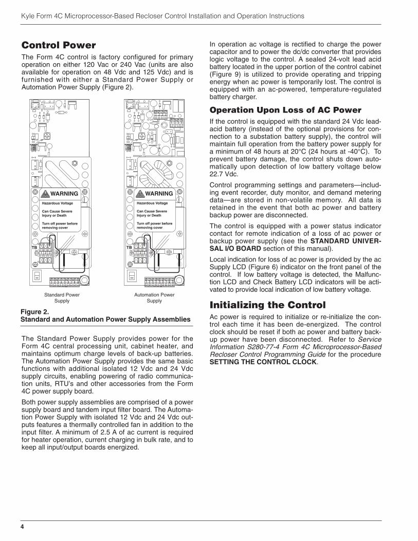
Control PowerThe Form 4C control is factory configured for primaryoperation on either 120 Vac or 240 Vac (units are alsoavailable for operation on 48 Vdc and 125 Vdc) and isfurnished with either a Standard Power Supply orAutomation Power Supply (Figure 2).
The Standard Power Supply provides power for theForm 4C central processing unit, cabinet heater, andmaintains optimum charge levels of back-up batteries.The Automation Power Supply provides the same basicfunctions with additional isolated 12 Vdc and 24 Vdcsupply circuits, enabling powering of radio communica-tion units, RTU’s and other accessories from the Form4C power supply board.
Both power supply assemblies are comprised of a powersupply board and tandem input filter board. The Automa-tion Power Supply with isolated 12 Vdc and 24 Vdc out-puts features a thermally controlled fan in addition to theinput filter. A minimum of 2.5 A of ac current is requiredfor heater operation, current charging in bulk rate, and tokeep all input/output boards energized.
In operation ac voltage is rectified to charge the powercapacitor and to power the dc/dc converter that provideslogic voltage to the control. A sealed 24-volt lead acidbattery located in the upper portion of the control cabinet(Figure 9) is utilized to provide operating and trippingenergy when ac power is temporarily lost. The control isequipped with an ac-powered, temperature-regulatedbattery charger.
Operation Upon Loss of AC PowerIf the control is equipped with the standard 24 Vdc lead-acid battery (instead of the optional provisions for con-nection to a substation battery supply), the control willmaintain full operation from the battery power supply fora minimum of 48 hours at 20°C (24 hours at -40°C). Toprevent battery damage, the control shuts down auto-matically upon detection of low battery voltage below22.7 Vdc.
Control programming settings and parameters—includ-ing event recorder, duty monitor, and demand meteringdata—are stored in non-volatile memory. All data isretained in the event that both ac power and batterybackup power are disconnected.
The control is equipped with a power status indicatorcontact for remote indication of a loss of ac power orbackup power supply (see the STANDARD UNIVER-SAL I/O BOARD section of this manual).
Local indication for loss of ac power is provided by the acSupply LCD (Figure 6) indicator on the front panel of thecontrol. If low battery voltage is detected, the Malfunc-tion LCD and Check Battery LCD indicators will be acti-vated to provide local indication of low battery voltage.
Initializing the ControlAc power is required to initialize or re-initialize the con-trol each time it has been de-energized. The controlclock should be reset if both ac power and battery back-up power have been disconnected. Refer to ServiceInformation S280-77-4 Form 4C Microprocessor-BasedRecloser Control Programming Guide for the procedureSETTING THE CONTROL CLOCK.
4
Kyle Form 4C Microprocessor-Based Recloser Control Installation and Operation Instructions
WARNING
Hazardous Voltage
Can Cause SevereInjury or Death
Turn off power beforeremoving cover
1 2 3
1 2 3 4 5 6 7 8 9
TB
1
23
0
AC MONITOR0--110/2201--120/2402--127/2543--120/240
Standard PowerSupply
Automation PowerSupply
WARNING
Hazardous Voltage
Can Cause SevereInjury or Death
Turn off power beforeremoving cover
1 2 3
1 2 3 4 5 6 7 8 9
TB
1
23
0
AC MONITOR0--110/2201--120/2402--127/2543--120/240
4321
4321
Figure 2.Standard and Automation Power Supply Assemblies

Line current flowing through the recloser is sensed bythree internally mounted bushing-current transformers inthe recloser, one for each phase. When the phase cur-rent or the zero-sequence (ground) current exceeds itsprogrammed minimum-trip value, the Kyle Form 4C con-trol initiates the programmed sequence of recloser-trip-ping and reclosing operations. If the fault is temporary,the control ceases to command recloser operations afterthe successful reclosure, and the control resets to thestart of its operating sequence after a preset time delay.If the fault is permanent, the control performs its com-plete programmed sequence of recloser commands andlocks out with the recloser open. Once locked-out, thecontrol must be reset to the start of its operatingsequence, which closes the recloser.
A functional block diagram of the Form 4C control opera-tion is shown in Figure 3. Line current conditions aremonitored continuously by three bushing-type currenttransformers in the recloser, one for each phase. Outputof these transformers is fed to the control front end whichconsists of isolation transformers and a 4:1 multiplexer.The control’s microprocessor samples the current andcomputes the RMS current for each phase and ground.
When current above the programmed minimum-trip levelis detected in one or more phases, the following chain ofevents will occur for an operating sequence of two fastand two delayed operations:
1. The overcurrent signal is integrated with time on theselected curve for the first trip operation to producethe signal which energizes the trip circuit.
2. Energizing the trip circuit connects the battery andcapacitor to the trip solenoid to open the recloser.
3. Simultaneously, the microprocessor starts timing onthe first reclosing interval-delay time.
4. Upon expiration of this reclosing interval-delay, aclosing signal is issued from the control, closing therecloser and selecting the time-current characteris-tics for the second trip operation.
If current remains above the minimum-trip level, thetripping and reclosing sequence (fast and delayedoperation) is repeated as programmed to lockout.
If the overcurrent is cleared before the operatingsequence reaches lockout, the microprocessor startstiming a reset-delay when the recloser closes intothe line and current is below minimum trip.
5. When the reset-delay times out, the control is resetto the home state and is ready for another pro-grammed operating sequence. If current rises aboveminimum trip prior to the reset-delay timing-out, thetimer is halted and the control continues the operat-ing sequence from where it left off and the accumu-lated reset-delay timing is cleared.
Ground fault tripping is separately programmable andincludes minimum trip, operations to lockout, and num-ber of operations on fast and delayed curves. Recloseand reset intervals are common for phase and groundfault operation.
5
S280-77-1!
SAFETYFOR LIFE
DESCRIPTION OF CONTROL
Control Operation
TripCircuit
CloseCircuit
A/DConverter
Memory
Microprocessor
Front PanelControl Switches
ControlFront End
RecloserMechanism
BCT's
Ø A
Ø B
Ø C
Gnd
Data Port
Keyboard
Display
Figure 3.Functional block diagram of Form 4C Control.
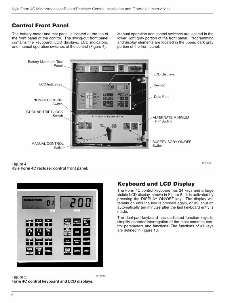
The battery meter and test panel is located at the top ofthe front panel of the control. The swing-out front panelcontains the keyboard, LCD displays, LCD indicators,and manual operation switches of the control (Figure 4).
Manual operation and control switches are located in thelower, light gray portion of the front panel. Programmingand display elements are located in the upper, dark grayportion of the front panel.
Keyboard and LCD DisplayThe Form 4C control keyboard has 24 keys and a largevisible LCD display, shown in Figure 5. It is activated bypressing the DISPLAY ON/OFF key. The display willremain on until the key is pressed again, or will shut offautomatically ten minutes after the last keyboard entry ismade.
The dual-pad keyboard has dedicated function keys tosimplify operator interrogation of the most common con-trol parameters and functions. The functions of all keysare defined in Figure 10.
6
Kyle Form 4C Microprocessor-Based Recloser Control Installation and Operation Instructions
Figure 4.Kyle Form 4C recloser control front panel.
961066KM
LCD Indicators
NON-RECLOSINGSwitch
GROUND TRIP BLOCKSwitch
Battery Meter and TestPanel
Keypad
LCD Displays
Data Port
SUPERVISORY ON/OFFSwitch
ALTERNATE MINIMUMTRIP Switch
MANUAL CONTROLSwitch
Figure 5.Form 4C control keyboard and LCD displays.
901022KM
Control Front Panel

Control Panel LCD IndicatorsTen LCD indicators (Figure 6), located to the left of thekeyboard and display, provide status information on con-trol and recloser functions. The operation of each LCD isdescribed as follows:
RECLOSER OPEN indicates that the recloser contactsare in the open position.
RECLOSER CLOSED indicates that the recloser con-tacts are in the closed position.
CONTROL LOCKOUT indicates that the control hastripped to lockout (no further automatic reclosing)sequence.
CURRENT ABOVE MINIMUM TRIP indicates that linecurrent is above the programmed minimum trip value.
GROUND TRIP BLOCKED indicates whether or notground trip block has been activated by either the frontpanel switch or via supervisory control.
NON-RECLOSING ACTIVE indicates whether or notnon-reclosing has been activated either by the frontpanel switch or via supervisory control.
MALFUNCTION indicates when one or more of the fivefollowing malfunctions is detected:
• Failure to close from a supervisory signal.
• Low/High battery voltage (resets automatically uponrestoration of normal battery voltage).
• Power down in less than 48 hours on battery power.
• Failure to close from the manual control switch.
• Internal diagnostics alarm.
Keyboard interrogation of Access Code 66 will display amalfunction code. Malfunction codes are listed on thelabel inside the cabinet door. To clear the MalfunctionLCD display, press the CLEAR key while Code 66 is dis-played.
ACCESSORY OPERATION identifies special accessoryoperations, where identification will aid in troubleshoot-ing. Access Code 65 will display the code identifying theaccessory:
• High-Current Lockout (Code 1)
• Remote Trip and Lockout (Code 2)
• Supervisory Trip and Lockout (Code 3)
A complete list of access codes, definitions, and para-meters is located in Service Information S280-77-4 Form4C Microprocessor-Based Recloser Control Program-ming Guide.
CHECK BATTERY indicates that the battery voltage islow (below 23.3 volts). The control’s power status indica-tor contact will also operate to provide remote indicationof low battery voltage.
AC SUPPLY indicates the presence of ac power whichis required for normal control operation.
Data Port on Control Front PanelThe Form 4C control is equipped with a data port locat-ed on the control front panel. It is used for temporaryconnection of a Data Reader or personal computer (witha data port-to-RS232 adapter) to the control. The dataport permits the operator or technician to download allthe programming information stored in the control,including operating parameters, event recorder, dutymonitor, demand metering, and load profile monitordata.
The data port also provides a convenient means toupload control parameters compared to manual key-board entry procedures at the control keyboard. SeeService Information S280-77-4 Form 4C Microproces-sor-Based Recloser Control Programming Guide foradditional information.
7
S280-77-1!
SAFETYFOR LIFE
RECLOSEROPEN
CONTROLLOCKOUT
GROUND TRIPBLOCKED
MALFUNCTION(CODE 66)
CHECKBATTERY
RECLOSERCLOSED
CURRENT ABOVEMINIMUM TRIP
NON-RECLOSINGACTIVE
ACCESSORYOPERATION(CODE 65)
ACSUPPLY
Figure 6.Control panel LCD indicators.
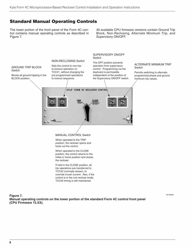
The lower portion of the front panel of the Form 4C con-trol contains manual operating controls as described inFigure 7.
All available CPU firmware versions contain Ground TripBlock, Non-Reclosing, Alternate Minimum Trip, andSupervisory ON/OFF.
8
Kyle Form 4C Microprocessor-Based Recloser Control Installation and Operation Instructions
Figure 7.Manual operating controls on the lower portion of the standard Form 4C control front panel(CPU Firmware 15.XX).
961066KM
GROUND TRIP BLOCKSwitch
Blocks all ground tripping in theBLOCK position.
NON-RECLOSING Switch
Sets the control to one trip-to-lockout operation onTCC#1, without changing thepre-programmed operationsto lockout sequence.
SUPERVISORY ON/OFFSwitch
The OFF position preventsoperation from supervisorycontrol. Programming via thekeyboard is permissibleindependent of the position ofthe Supervisory ON/OFF switch.
ALTERNATE MINIMUM TRIPSwitch
Permits switching to alternateprogrammed phase and groundminimum trip values.
MANUAL CONTROL Switch
When operated to the TRIPposition, the recloser opens andlocks out the control.
When operated to the CLOSEposition, the control returns to theinitial or home position and closesthe recloser.
If held in the CLOSE position, alltrip operations are transferred toTCC#2 (normally slower), tooverride inrush current. Also, if thecontrol is in the non-reclose mode,TCC#2 timing is still maintained.
Standard Manual Operating Controls
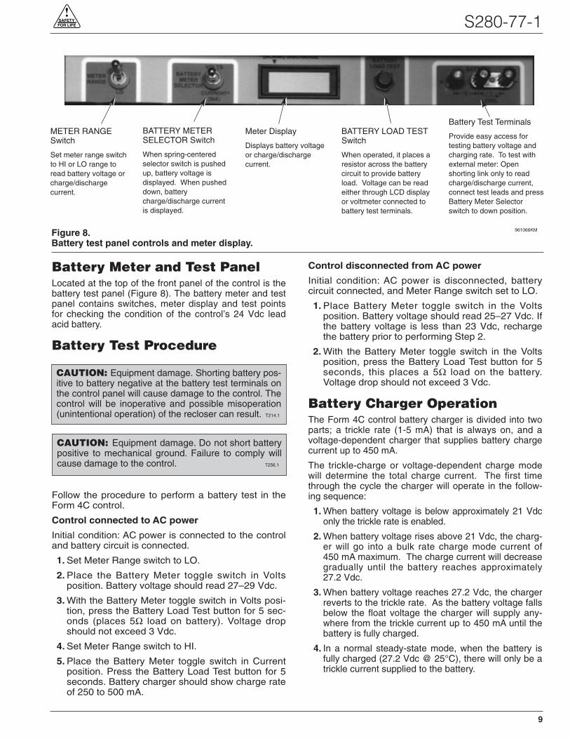
Battery Meter and Test PanelLocated at the top of the front panel of the control is thebattery test panel (Figure 8). The battery meter and testpanel contains switches, meter display and test pointsfor checking the condition of the control’s 24 Vdc leadacid battery.
Battery Test Procedure
Follow the procedure to perform a battery test in theForm 4C control.
Control connected to AC power
Initial condition: AC power is connected to the controland battery circuit is connected.
1. Set Meter Range switch to LO.
2. Place the Battery Meter toggle switch in Voltsposition. Battery voltage should read 27–29 Vdc.
3. With the Battery Meter toggle switch in Volts posi-tion, press the Battery Load Test button for 5 sec-onds (places 5Ω load on battery). Voltage dropshould not exceed 3 Vdc.
4. Set Meter Range switch to HI.
5. Place the Battery Meter toggle switch in Currentposition. Press the Battery Load Test button for 5seconds. Battery charger should show charge rateof 250 to 500 mA.
Control disconnected from AC power
Initial condition: AC power is disconnected, batterycircuit connected, and Meter Range switch set to LO.
1. Place Battery Meter toggle switch in the Voltsposition. Battery voltage should read 25–27 Vdc. Ifthe battery voltage is less than 23 Vdc, rechargethe battery prior to performing Step 2.
2. With the Battery Meter toggle switch in the Voltsposition, press the Battery Load Test button for 5seconds, this places a 5Ω load on the battery.Voltage drop should not exceed 3 Vdc.
Battery Charger OperationThe Form 4C control battery charger is divided into twoparts; a trickle rate (1-5 mA) that is always on, and avoltage-dependent charger that supplies battery chargecurrent up to 450 mA.
The trickle-charge or voltage-dependent charge modewill determine the total charge current. The first timethrough the cycle the charger will operate in the follow-ing sequence:
1. When battery voltage is below approximately 21 Vdconly the trickle rate is enabled.
2. When battery voltage rises above 21 Vdc, the charg-er will go into a bulk rate charge mode current of450 mA maximum. The charge current will decreasegradually until the battery reaches approximately27.2 Vdc.
3. When battery voltage reaches 27.2 Vdc, the chargerreverts to the trickle rate. As the battery voltage fallsbelow the float voltage the charger will supply any-where from the trickle current up to 450 mA until thebattery is fully charged.
4. In a normal steady-state mode, when the battery isfully charged (27.2 Vdc @ 25°C), there will only be atrickle current supplied to the battery.
9
S280-77-1!
SAFETYFOR LIFE
Figure 8.Battery test panel controls and meter display.
961066KM
METER RANGESwitch
Set meter range switchto HI or LO range toread battery voltage orcharge/dischargecurrent.
BATTERY METERSELECTOR Switch
When spring-centeredselector switch is pushedup, battery voltage isdisplayed. When pusheddown, batterycharge/discharge currentis displayed.
Meter Display
Displays battery voltageor charge/dischargecurrent.
BATTERY LOAD TESTSwitch
When operated, it places aresistor across the batterycircuit to provide batteryload. Voltage can be readeither through LCD displayor voltmeter connected tobattery test terminals.
Battery Test Terminals
Provide easy access fortesting battery voltage andcharging rate. To test withexternal meter: Openshorting link only to readcharge/discharge current,connect test leads and pressBattery Meter Selectorswitch to down position.
CAUTION: Equipment damage. Shorting battery pos-itive to battery negative at the battery test terminals onthe control panel will cause damage to the control. Thecontrol will be inoperative and possible misoperation(unintentional operation) of the recloser can result. T214.1
CAUTION: Equipment damage. Do not short batterypositive to mechanical ground. Failure to comply willcause damage to the control. T256.1

Battery Charging with PortableChargerIf it is not possible to charge the battery with the control’sbuilt-in charger, a KA43ME7001 (120 Vac) portablebench type battery charger is available. Refer to S280-79-14 KA43ME7001 Portable Lead Acid Battery ChargerInstructions for additional information.
Charge the battery with a KA43ME7001 (120 Vac)portable charger as applicable:
1. Remove the control from service. Refer to Removethe Control from Service procedure within the Test-ing and Troubleshooting section of this manual.
2. Remove the battery from the control and carefullytransport it to a suitable service facility.
3. Connect the battery directly to the KA43ME7001charger. The charger continuously monitors the bat-tery voltage.
Note: A red LED indicator on the body of the charger illu-minates when charging.
The red LED blinks to indicate the battery hasreached a full charge. This process can take up to 24hours.
Battery Reference InformationBattery: Hawker Cyclon
Catalog Part #: KME4-215
Voltage: 24 Vdc
Type: Lead Acid
Amp/Hour: 8
Bench TestLoad Condition
for 5 seconds: 5Ω, 55 Watt
AcceptableVoltage Drop at
End of Test Load: 3V or Less
Initial Programming Prior toInstallationThe control must be programmed with all necessaryoperating settings and parameters prior to operation withan energized recloser.
Initial programming of the Form 4C control is the respon-sibility of a qualified technician or engineer who is famil-iar with the functions of the control and the programmingparameters required for the specific recloser installation.The control can be programmed from the keyboard, dataport, or a digital communications accessory.
Service Information S280-77-4 Form 4C Microproces-sor-Based Recloser Control Programming Guide lists allaccess codes, program settings, and detailed operatingdescriptions of the code parameters. All control programsettings, parameter descriptions, and programmingaccess codes are also listed on the control informationlabel located inside the cabinet door.
Control SecurityThe Form 4C control has a security system which limitsaccess to only those control functions appropriate to theoperator’s responsibilities, and requires the keyboardentry of a four-digit security code. It prohibits unautho-rized access to programming and operating parameters.Interrogation of the control to display operating parame-ters and read-only functions of the control does notrequire entering a security code.
Service Information S280-77-4 Programming Guide listsall control program settings along with their keyboardaccess codes, and the security level required to makeprogramming changes.
10
Kyle Form 4C Microprocessor-Based Recloser Control Installation and Operation Instructions
CAUTION: Equipment misoperation. Do notconnect this control to an energized recloser
until all control settings have been properly pro-grammed and verified. Refer to the programminginformation for this control. Failure to comply canresult in control and recloser misoperation, equip-ment damage, and personal injury. G110.3
!CAUTION: Recloser misoperation. The controlmust be removed from service before discon-
necting the control battery. Removing the control bat-tery from an in-service control may cause reclosermisoperation (unintentional operation) Failure to com-ply can result in equipment damage or personal injury.
T213.4
!
IMPORTANT: Do not attempt to charge a lead acidbattery below 19 Vdc with the KA43ME7001 charger.Attempting to do so will damage the charger.

Control Back PanelThe control battery, cabinet heater, power supply, Stan-dard Universal I/O board, and Optional Universal I/Oboard, are located inside the control cabinet on the backpanel of the control as shown in Figure 9.
11
S280-77-1!
SAFETYFOR LIFE
Power CapacitorControl Battery
OptionalUniversal I/OBoard
AC Supply InputTerminal Block
WARNING: Hazardous Voltage. Turn off powerbefore removing safety shield. Failure to do so can
result in contact with high voltage which will cause deathor severe personal injury. T261.0
!
Clear Safety Shield
AC Power SupplyAssembly
StandardUniversal I/O
Board
CabinetGround
Block
Figure 9.Inside back panel of Form 4C control shown with Automation Power Supply.
99011KM

12
Kyle Form 4C Microprocessor-Based Recloser Control Installation and Operation Instructions
Interrogates or programs
minimum trip(Phase and
Ground)
"1" numeric value
Interrogates or programs 1st
TCC (Phase and
Ground)
"2" numeric value
Interrogates or programs 2nd
TCC(Phase and
Ground)
"3" numeric value
Interrogates or programs number of trip operations on 1st
TCC(Phase and Ground)
"4" numeric value
Interrogates or programs number of
operations to lock-out (Phase and Ground)
"5" numeric value
Interrogates or programs reset after successful reclose
delay time.
"6" numeric value
Interrogates or programs reclosing
time after 1st trip operation.
"7" numeric value
Interrogates or programs reclosing time after 2nd trip
operation.
"8" numeric value
Interrogates or programs reclosing time after 3rd trip
operation.
"9" numeric value
Toggles between Phase and
Ground Display
Checks LCD operation by displaying all
numeric segments and messages.
"0" numeric value
Permits display of the programmed values of most common control
operating features.
SCROLL
Displays Phase and Ground load current and demand meter
readings.
Turns keyboard and display ON and OFF.
TARGETS
TARGET COUNTERS
CURRENT METERING
DISPLAY ON
OFF
Displays fault target information.
Displays cumulative total of fault current trip
operations for each phase and ground.
(Used with SELECT LOWER FUNCTION
key)
Provides direct entry of access codes
Clears pending keyboard entries; resets
targets, counters and demand drag hand.
OPER. COUNTER
SEQUENCE POSITION
CODE CLEAR
Displays total number of control trip operations.
Displays control operating sequence position. (Used with SELECT LOWER FUNCTION key)
Provides access to Target Counters and Sequence Position
Escape key ignores recent keystroke and
returns to ready (rdY) prompt.
Enters changed parameter into
program.
SELECT LOWER
FUNCTIONESCAPE ENTER
Displays status of individual control
features with programmable values.
Displays individual parameters of
programmable control features and accessories.
Initiates change to programmed parameter.
SELECT ACCESSORY
ACCESSORY SCROLL CHANGE
DISPLAY TEST
0
MINIMUM TRIP
PHASE
GROUND
1
OPER. TO L.O.
5
TCC 1
2
TCC 2
3
OPER 1ST. TCC
4
RESET TIME
6
RECLOSE 1
7
RECLOSE 2
8
RECLOSE 3
9
Figure 10.Keyboard functions.
Keyboard FunctionsPrior to interrogation and programming, the operator should be familiar with the control’s keyboard. Figure 10 showseach key and its description and operation.

During interrogation and programming, the LCD displaysprovide a readout of all keyboard operations (Figure 11).The left display shows the program access code enteredand indicates whether the control is in the EXAMINE,SCROLL, or CHANGE mode. PHASE or GROUND willappear if the parameter has a phase or ground value.The right display will show a parameter value up to fourdigits.
EXAMINE indicates that the displayed access code isbeing interrogated.
SCROLL indicates the SCROLL key can be used toobtain additional information.
CHANGE indicates the displayed access code is beingchanged.
13
S280-77-1!
SAFETYFOR LIFE
Interpreting the LCD Displays
EXAMINE PHASESCROLL CODECHANGE GROUND
CODE VALUE
Display Message
Program Access Code Parameter Value
Indicates a modified TCC
Figure 11.Interpreting the LCD display.
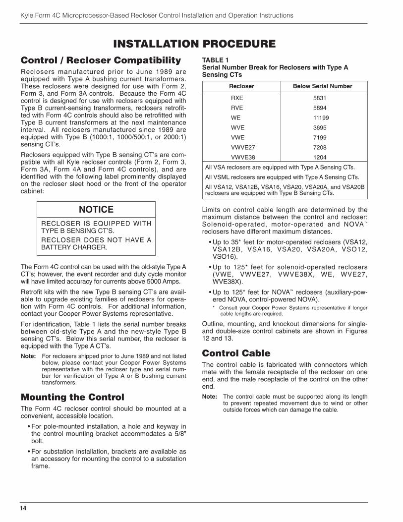
Control / Recloser CompatibilityReclosers manufactured prior to June 1989 areequipped with Type A bushing current transformers.These reclosers were designed for use with Form 2,Form 3, and Form 3A controls. Because the Form 4Ccontrol is designed for use with reclosers equipped withType B current-sensing transformers, reclosers retrofit-ted with Form 4C controls should also be retrofitted withType B current transformers at the next maintenanceinterval. All reclosers manufactured since 1989 areequipped with Type B (1000:1, 1000/500:1, or 2000:1)sensing CT’s.
Reclosers equipped with Type B sensing CT’s are com-patible with all Kyle recloser controls (Form 2, Form 3,Form 3A, Form 4A and Form 4C controls), and areidentified with the following label prominently displayedon the recloser sleet hood or the front of the operatorcabinet:
The Form 4C control can be used with the old-style Type ACT’s; however, the event recorder and duty cycle monitorwill have limited accuracy for currents above 5000 Amps.
Retrofit kits with the new Type B sensing CT’s are avail-able to upgrade existing families of reclosers for opera-tion with Form 4C controls. For additional information,contact your Cooper Power Systems representative.
For identification, Table 1 lists the serial number breaksbetween old-style Type A and the new-style Type Bsensing CT’s. Below this serial number, the recloser isequipped with the Type A CT’s.
Note: For reclosers shipped prior to June 1989 and not listedbelow, please contact your Cooper Power Systemsrepresentative with the recloser type and serial num-ber for verification of Type A or B bushing currenttransformers.
Mounting the ControlThe Form 4C recloser control should be mounted at aconvenient, accessible location.
• For pole-mounted installation, a hole and keyway inthe control mounting bracket accommodates a 5/8”bolt.
• For substation installation, brackets are available asan accessory for mounting the control to a substationframe.
Limits on control cable length are determined by themaximum distance between the control and recloser:Solenoid-operated, motor-operated and NOVA™
reclosers have different maximum distances.
• Up to 35* feet for motor-operated reclosers (VSA12,VSA12B, VSA16, VSA20, VSA20A, VSO12,VSO16).
• Up to 125* feet for solenoid-operated reclosers(VWE, VWVE27, VWVE38X, WE, WVE27,WVE38X).
• Up to 125* feet for NOVA™ reclosers (auxiliary-pow-ered NOVA, control-powered NOVA).* Consult your Cooper Power Systems representative if longer
cable lengths are required.
Outline, mounting, and knockout dimensions for single-and double-size control cabinets are shown in Figures12 and 13.
Control CableThe control cable is fabricated with connectors whichmate with the female receptacle of the recloser on oneend, and the male receptacle of the control on the otherend.
Note: The control cable must be supported along its lengthto prevent repeated movement due to wind or otheroutside forces which can damage the cable.
14
Kyle Form 4C Microprocessor-Based Recloser Control Installation and Operation Instructions
INSTALLATION PROCEDURE
NOTICERECLOSER IS EQUIPPED WITHTYPE B SENSING CT’S.RECLOSER DOES NOT HAVE ABATTERY CHARGER.
TABLE 1Serial Number Break for Reclosers with Type ASensing CTs
Recloser Below Serial Number
RXE 5831
RVE 5894
WE 11199
WVE 3695
VWE 7199
VWVE27 7208
VWVE38 1204
All VSA reclosers are equipped with Type A Sensing CTs.
All VSML reclosers are equipped with Type A Sensing CTs.
All VSA12, VSA12B, VSA16, VSA20, VSA20A, and VSA20Breclosers are equipped with Type B Sensing CTs.

Grounding the Control
The control cabinet must be grounded. A groundingconnector on the underside of the cabinet will accommo-date No. 14 solid through No. 4 stranded conductors.Suggested methods for grounding the control andrecloser are shown in Figures 14, 15 and 16.
It is important for effective surge protection that all con-trol and power conductors for the Form 4C be routedparallel to a corresponding ground path. For example,the ac power supply for the control should be parallel toand equal in length to the transformer ground path. Thecontrol cable should be parallel to and routed close tothe recloser ground path.
15
S280-77-1!
SAFETYFOR LIFE
IMPORTANT: All external inputs to the Form 4C con-trol must be routed within 8 inches of their corre-sponding ground. During a surge, a potential ofapproximately 1.5 kV per foot can develop in the con-ductors. Differences between conductor and groundpath lengths can add additional stress to the controlcomponents in the event of a power surge.
Control Weight 32,66 kg (72 Lbs)
279,4(11.0)
339,9(13.38)
25,4(1.0)
Male Receptaclefor Control Cable
558,8(22.0)
GroundingTerminal Lug
76,2(3.0)
165,1(6.5)
454,
2(1
7.88
)
511,
3(2
0.13
)
Use No. 14 to No. 4Stranded Wire
38,1 (1.5)309,6
(12.19)
28,6 (1.13) Hole inLifting Lug
203,2(8.0)
38,1(1.50)
406,4(16.0)
Mtg Holesfor 16,0 (.63) MaxBolt Dia.*
(16,0) .63 HoleProvided forCustomer Lock
127,0(5.00)
9,5 (.38)
95,2(3.75)
161,9(6.38)
95,2 (3.75)
Vac InputConnection Hole34,1 (1.34)
RemovableCap-Plugs forRemote AndSupervisory Input34,0 (1.34) Dia.
Vent
Vent
Male Receptaclefor Control Cable
19,0 (.75) Holefor Locking Handle
* Customer provided hardware
NOTE: Unless otherwise specified, all dimensions are mm (inches).
Figure 12.Single-size cabinet mounting dimensions.
882,65(34.75)
203,2(8.0)
406,4(16.0)
279,4(11.0)
342,9(13.5)
30,23 (1.19)
Male Receptaclefor Control Cable
991,4(39.03)
939,8(37.0)
309,6(12.19)
(16,0) .63 Dia.Hole Providedfor CustomerLock
Mtg Holes for16,0 (.63) max Bolt Dia.*
38,1 (1.50)
Control Weight 41,7 kg (92 Lbs.)
165,1(6.5)
GroundingTerminal Lug
* Customer provided hardware
NOTE: Unless otherwise specified, all dimensions are mm (inches).
Figure 13.Double-size cabinet mounting dimensions.
WARNING: Hazardous Voltage. Recloser andcontrol must be solidly grounded. Follow all
locally approved procedures and safety practiceswhen grounding this equipment. Improper groundingcan result in contact with high voltage, which willcause death or severe personal injury. G115.1
!

Installation of the control must include the following:
• Protection of the recloser bushings and the supplyingtransformer with lightning arresters
• Grounding of the recloser head
• Grounding of the transformer tank
• Grounding of the control cabinet
• Grounding of the SCADA equipment (if present)
For 4-wire Multi-Grounded Systems
For 3-wire Ungrounded and Impedance GroundedSystems
The use of a grounding mat may be required dependingupon the local safety regulations defining the permissi-ble step and touch potential levels. Consult local regula-tions for proper grounding procedures.
16
Kyle Form 4C Microprocessor-Based Recloser Control Installation and Operation Instructions
SurgeArrester
RecloserHeadGround
Transformer
SurgeArrester
ArresterGround
Recloser
Pole
SupplyVoltage
PoleGround
Form 4CControl
NE
UH
OT
GNDNEUHOT
InputTerminalBlock
ControlCable
Customer Ground Connectionat External Lug
Electrical Connections - Line to Neutralconnected transformer
HOT
NEUTRAL
Form 4C Control
SupplyVoltage
Transformer
Electrical Connections - Line to Line connected transformer
SupplyVoltage
NEUTRAL
HOT
TransformerLine
toLine
Voltage
Input Terminal Block
External Ground Lug
Form 4C Control
Figure 14.Recommended grounding method for Form 4C Control installed on 4-wire multi-grounded, impedancegrounded, or 3-wire ungrounded systems with local supply transformer.
IMPORTANT: In pole-mounted applications, aground connection must be made between the reclos-er, transformer, recloser control, and SCADA equip-ment for proper protection of the equipment. The poleground conductor size (current carrying capacity)should be the same or greater than the primary over-head conductor.
Grounding: 4-wire Multi-Grounded, Impedance Grounded, 3-wire Ungroundedwith Local Supply Transformer

Installation of the control must include the following:
• Protection of the recloser bushings and the supplyingtransformer with lightning arresters
• Grounding of the recloser head
• Grounding of the transformer tank
• Grounding of the control cabinet
• Grounding of the SCADA equipment (if present)
17
S280-77-1!
SAFETYFOR LIFE
Figure 15.Recommended grounding method for Form 4C Control installed on 4-wire multi-grounded, impedancegrounded, or 3-wire ungrounded systems with remote supply voltage transformer.
IMPORTANT: In pole-mounted applications, aground connection must be made between the reclos-er, transformer, recloser control, and SCADA equip-ment for proper protection of the equipment. The poleground conductor size (current carrying capacity)should be the same or greater than the primary over-head conductor.
IMPORTANT: All external inputs to the Form 4C con-trol must be routed within 8 inches of their corre-sponding ground. During a surge, a potential ofapproximately 1.5 kV per foot can develop in the con-ductors. Differences between conductor and groundpath lengths can add additional stress to the controlcomponents in the event of a power surge.
Grounding: 4-wire Multi-grounded, Impedance Grounded, 3-wire Ungrounded with Remote Supply Voltage Transformer
NOTE: Distance between transformer and recloser should be one pole span or less.
RecloserHead Ground
Supply Voltage
Pole Ground
Recloser
Pole
SurgeArrester
Transformer
Form 4C Control
HOTNEUGND
NE
UH
OT
Input TerminalBlock
Control Cable
Surge Arrester
ArresterGround
Customer Ground ConnectionAt External Lug
System
Neutral
Pole
Electrical Connections - Low voltage distribution network using isolation transformer
(typical international connection shown)
115 VacSupply Voltage
HOT
NEUTRAL
Local Isolation Transformer
Customer Supplied Low Voltage
Form 4C Control
Low Voltage Arrester
InputTerminal Block
ExternalGround Lug
Form 4C Control
Electrical Connections -Remote dedicated supply transformer
TransformerHOT
NEUTRAL
Supply Voltage InputTerminal Block
ExternalGround Lug
Installation of the control must include the following:
• Protection of the recloser bushings and the supply-ing transformer with lightning arresters
• Grounding of the recloser head
• Grounding of the transformer tank
• Grounding of the control cabinet
• Grounding of the SCADA equipment (if present)
18
Kyle Form 4C Microprocessor-Based Recloser Control Installation and Operation Instructions
Electrical Connections - Line to Neutral connected transformer
Form 4C Control
SupplyVoltage
Transformer
Input TerminalBlock
External Ground Lug
SurgeArrester
RecloserHeadGround
Recloser
ArresterGround
SupplyVoltage
InputTerminalBlock N
EU
HO
T
PoleGround
ControlCable
Form 4CControl
Customer Ground ConnectionAt External LugControl Height Must Be
a Minimum of 3 Meters (10 ft.) Above Earth
SurgeArrester
GNDNEUHOT
HOT
NEUTRAL
Figure 16.Recommended grounding method for Form 4C Controlinstalled on a 3-wire uni-grounded system.
IMPORTANT: All external inputs to the Form 4C con-trol must be routed within 8 inches of their corre-sponding ground. During a surge, a potential ofapproximately 1.5 kV per foot can develop in the con-ductors. Differences between conductor and groundpath lengths can add additional stress to the controlcomponents in the event of a power surge.
IMPORTANT: In pole-mounted applications, aground connection must be made between the reclos-er, transformer, recloser control, and SCADA equip-ment for proper protection of the equipment. The poleground conductor size (current carrying capacity)should be the same or greater than the primary over-head conductor.
WARNING: Hazardous Voltage. Use locallyapproved operator safety procedures for proper
insulation when maintaining this equipment. High Volt-age step and touch potential is characteristic in uni-ground systems. Failure to comply can cause death orsevere personal injury. T262.0
!
CAUTION: Exported Potential. Do not makedirect electrical connections to remote devices.
All SCADA equipment must be mounted locally or con-nected using the fiber-optic or radio communicationaccessory. Direct connections to remote devices canproduce exported potential causing equipment dam-age or personal injury. T263.0
!
CAUTION: Hazardous Voltage. Do not use ashared low voltage network to power the control
unless specifically designed to withstand maximumground potential rise. Ground faults on a high voltagenetwork can create a rise in ground potential. T264.0
!
Grounding: 3-wire Uni-Grounded

S280-77-1!
SAFETYFOR LIFE
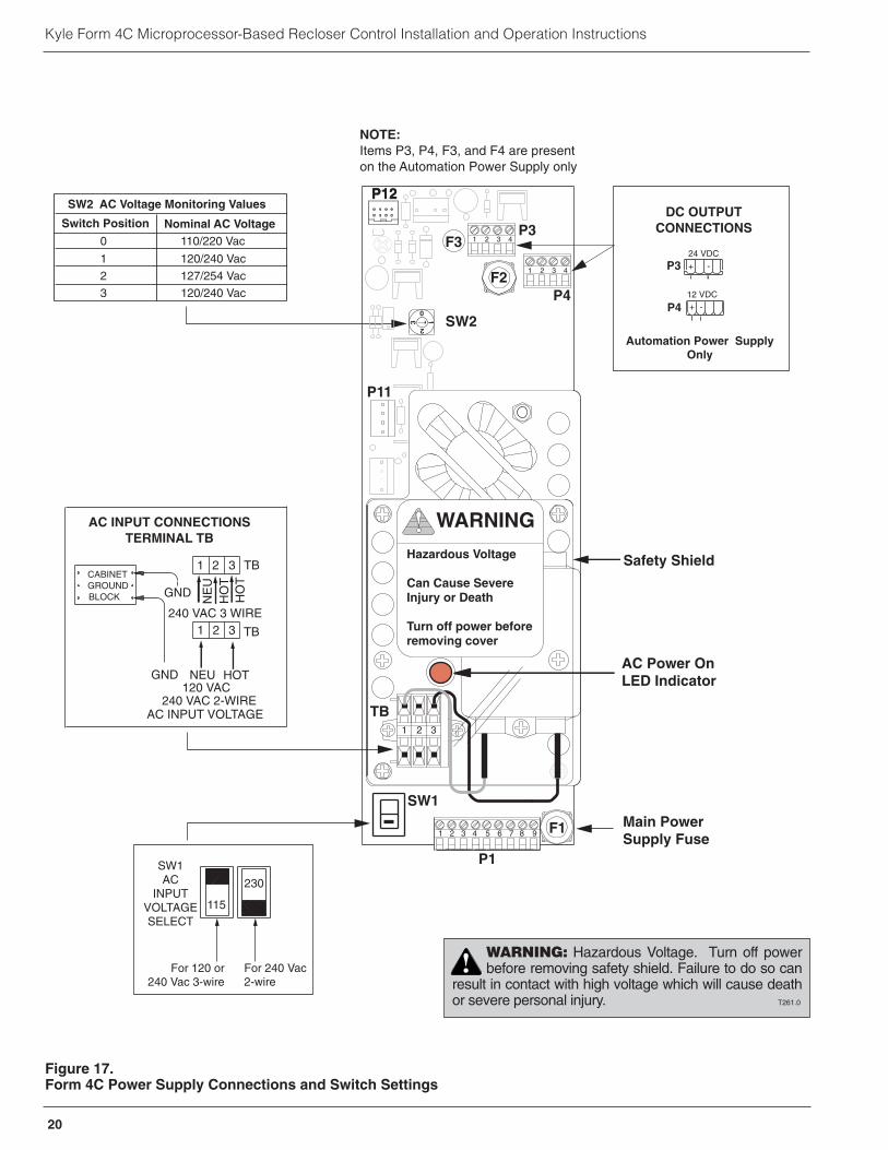
Customer Connections for ACPowerAll Form 4C controls not supplied with a dc-dc supplyadapter require customer-supplied ac power for opera-tion. Ac voltage of 120/240 Vac@50/60 Hz is requiredfor proper operation of the power supply and control.Power to the control is provided via the ac power supplywhich is factory configured for either 120 or 240 voltoperation. The maximum operating current requirementfor the control is approximately 2.5 amps.
Customer furnished ac power leads are brought into thecontrol through a knockout hole in the bottom right sideof the control cabinet. Input leads are terminated at theac input terminal block TB (see Figure 9) of the powersupply located behind the plastic safety shield in thelower right-hand corner of the back panel of the controlcabinet.
The ac power supply input terminal (Figure 17) enablesconnection of either 120 Vac or 240 Vac source voltage.Power supply input voltage selector switch SW-1(Figure17) allows selection of either 115 or 230 Vac input voltages.
Selector switch SW2 (Figure 17) establishes the thresh-old voltage used to monitor and detect the loss of ACline voltage. The threshold reference is approximately80% of the selected nominal voltage. Selectable valuesof 110/220, 120/240 and 127/254 Vac enables monitor-ing of local values common to most domestic and inter-national nominal voltages.
Refer to Figure 17 and 18 for connection diagrams.Ground the control cabinet to the pole through the exter-nal cabinet ground lug (Figure 12).
Note: It is not necessary to use shielded cable if the ac sup-ply path is running next to the transformer groundpath.
Customer Connections forRemote and SupervisoryOperationFigure 18 shows customer connections for the 19-posi-tion Standard Universal I/O terminal block and for the30-position Optional Universal I/O block. The terminalblock connectors will accommodate conductor leads upto 12 AWG maximum. External lead resistance must notexceed 200 ohms.
CAUTION: Equipment damage. Do not drill connec-tion holes into the top of the cabinet. Connection holesin the top of the cabinet will allow moisture to seep intothe control and damage the components or cause con-trol misoperation. Failure to comply will void the con-trol’s factory warranty. T249.0
IMPORTANTShielding and Surge Protectionof Supervisory CablesAll supervisory operation and control monitor leadsmust be protected within shielded cables. For 120 Vaccontrol power, the input voltage COMMON wire mustbe grounded at the source and connected to the Stan-dard Universal I/O Terminal Block at Terminal 18 or 19.A single common wire can be used for multiple inputsif it is jumpered at the I/O board terminals. The cableshield must be grounded at the Form 4C control only,see Figure 19.
All remote operation and monitor leads must be pro-tected with metal oxide varistors (MOV’s) 320 Vac,160 Joules, or equivalent (Figure 19).
19
CAUTION: Equipment damage; misoperation.External leads must be shielded and the shield mustbe grounded at both ends. Terminate each lead witha 320 Vac, 160 Joules metal oxide resistor (MOV),or equivalent, at the remote end. Attach MOVsbetween the leads and ground. Failure to properlyshield and protect leads can result in equipmentdamage and/or unintentional operation. G117.3
20
Kyle Form 4C Microprocessor-Based Recloser Control Installation and Operation Instructions
230
115
SW1AC
INPUTVOLTAGESELECT
AC INPUT CONNECTIONS TERMINAL TB
TB1 2 3
GND
NE
U
HO
TH
OT
CABINETGROUNDBLOCK
240 VAC 3 WIRE1 2 3 TB
GND NEU HOT
240 VAC 2-WIREAC INPUT VOLTAGE
120 VAC
WARNING
Hazardous Voltage
Can Cause SevereInjury or Death
Turn off power beforeremoving cover
1
23
0
F1
1 2 3
P12
SW2
1
P11
2 3 4 5 6 7 8 9
P1
TB
Safety Shield
SW1
AC Power OnLED Indicator
SW2 AC Voltage Monitoring Values
Switch Position Nominal AC Voltage
1 120/240 Vac
2 127/254 Vac
3 120/240 Vac
0 110/220 Vac
Main Power Supply Fuse
For 120 or240 Vac 3-wire
For 240 Vac2-wire
P12
4321
4321F2
F3
P4
P3
NOTE: Items P3, P4, F3, and F4 are present on the Automation Power Supply only
DC OUTPUTCONNECTIONS
P4 + -12 VDC
+ -24 VDC
P3
Automation Power SupplyOnly
Figure 17.Form 4C Power Supply Connections and Switch Settings
WARNING: Hazardous Voltage. Turn off powerbefore removing safety shield. Failure to do so can
result in contact with high voltage which will cause deathor severe personal injury. T261.0
!

S280-77-1!
SAFETYFOR LIFE
Ratings Table For Output Status Contacts
Contact Rating
1 A
2 A
2 A
1 A
0.6 A
Input Voltage
120 Vac
12 Vdc
24 Vdc
48 Vdc
125 Vdc
* Relay Contacts Shown For The Indicated Status
BLOCK OF CLOSE
ACCESSORY120/240 Vac
REMOTE TRIP &
LOCKOUT
CUSTOMER SUPPLIEDVOLTAGE INPUTS
DETAIL "B"STANDARD UNIVERSAL I/O BOARD
TERMINAL BLOCKCUSTOMER SUPPLIED
VOLTAGE INPUTS
SU
PV
. TR
IP &
L.O
.
SU
PV
. CL
OS
E
SU
PV
. CO
MM
ON
SU
PV
. CO
MM
ON
SUPV. SWITCH STATUS
(SUPV. OFF)*
POWERSTATUS
(NORMAL)*RECLOSER
STATUS(RECLOSER CLOSED)*
MALFUNCTIONSTATUS
(NO MALF.) INTERNALCONNECTION
DETAIL "A"OPTIONAL UNIVERSAL I/O BOARD
TERMINAL BLOCK
GRD. TRIP BLOCKSTATUS
(GRD. TRIPNORMAL)*
NON-RECLOSING
STATUS(NORMAL
RECLOSE)*
ALT. MIN.TRIP
STATUS(NORMAL)*
CONTROLLOCKOUTSTATUS
(NOT LOCKOUT)*
FAULTTARGET
1-2 (PHASE)**
FAULTTARGET
3-4(GROUND)**
FAULTTARGET
5-6(SGF) **
CUSTOMER SUPPLIED VOLTAGE INPUTS
SU
PV
. GR
D. T
RIP
BL
OC
K
SU
PV
. NO
N-R
EC
LO
SIN
G †
SU
PV
. AL
T. M
IN. T
RIP
SU
PV
. TR
IP
SU
PV
. OP
T1
SU
PV
. OP
T2
SU
PV
. CO
MM
ON
** Target Designation When Sensitive Ground/Earth Fault Is Enabled (Access Code 120)
OPT2STATUS
(Not Active)
6 7 851 2 43 9 10 11 141312 15 16 17 20 211918 2322 24 25 26 29 302827
OPT1STATUS
(Not Active)
1 2 43 7 865 9 16 17 1918121110 13 14 15
Operating Current Requirements ForRemote Trip And Lockout Input
Nominal CurrentInput Voltage
12 Vdc - 125 Vdc120 Vac - 240 Vac
3 mA
Input Voltage12 Vdc - 125 Vdc120 Vac - 240 Vac
Nominal Current
3 mA
Operating Current Requirements ForStandard And Optional Supervisory Inputs
MinimumOperating Time
0.25 seconds
LTCDSTATUS(Normal)
Ratings Table For LTCD Status
Contact Rating
4 A
0.25 A
4 A
Input Voltage
12 Vdc - 48 Vdc
125 Vdc
120 Vac - 240 Vac
Note: OPT1 and OPT2 are used for optional accessories identified in the ACCESSORIES section of this manual.
† When SWITCH MODE firmware accessory is ON, Supervisory Non-Reclose is replaced by Supervisory Target Reset.
1-11/32" Dia. HolesFor AccessoryOr Customer Input(Caplugs installed)
DigitalCommunicationsBoard Accessory
1-11/32" Dia. HoleFor ac Supply Input
Optional UniversalI/O Board
Terminal BlockSee Detail "A"
Standard UniversalI/O Board
Terminal BlockSee Detail "B"
Control CableReceptacle
6 7 851 2 43 9 10 11 141312 15 16 17 20 211918 2322 24 25 26 29 302827
7 8 9 121110 13 14 15 16 17 19181 2 43 65
Connect ground cable to grounding blockwith supplied hardware.
1 2 3 4 5 6 7 8 9
WARNING
Hazardous Voltage
Can Cause SevereInjury or Death
Turn off Power beforeremoving cover
F1
1 2 3
TB
1
23
0
4321
4321
P4
P3
SW2
SW1
AC INPUTCONNECTIONS
TB1 2 3
GND
NE
U
HO
TH
OT
CABINETGROUNDBLOCK
240 VAC 3 WIRE1 2 3 TB
GND NEU HOT
240 VAC 2-WIREAC INPUT VOLTAGE
230115
SW1INPUT
VOLTAGESELECT
120 VAC
+ -
CONNECTIONSDC OUTPUT
24 VDC
P3 + -12 VDC
P4
Automation Power Supply Only
Figure 18.Form 4C Control Customer Connections Diagram.
21

Kyle Form 4C Microprocessor-Based Recloser Control Installation and Operation Instructions
G
R
FORM 4C CONTROL REMOTE BOX
BLOCK OF CLOSE
REMOTETRIP & L.O.
SUPV. SWITCH.STATUS
POWERSTATUS
RECLOSERSTATUS
MALFUNCTIONSTATUS
SUPV.COMMON
INTERNALCONNECTION
SUPV. CLOSE
SUPV. TRIP & L.O.
OPTIONAL UNIVERSALI/O BOARD
STANDARD UNIVERSAL I/O BOARD
Not All RemoteConnections
Shown
120Vacor 240VacHOT
120Vacor 240VacNEUTRAL
INPUTVOLTAGE
COMMON*
REMOTECONTACTS
INPUTVOLTAGE
COMMON*
REMOTECONTACTS
INPUTVOLTAGE
COMMON*SHIELD
Factory Jumper
* A Single common wire can be used for multiple inputs if it is jumpered at the I/O board terminals
NOTES: Arresters to be metal oxide varistors (MOVs) 320 Vac, 160 Joules or equivalent. External lead resistance must not exceed 200 ohms.
67
85
12
43
910
1114
1312
1516
1720
1918
2123
2224
2526
2930
2827
78
912
1110
1314
1516
1719
181
24
36
5
Figure 19.Shielding and Surge Protection for Supervisory and Remote Cables.
22

The Form 4C control includes a Standard Universal I/O Board for supervisory and remote operation and indication.
The Standard Universal I/O Board requires customerprovided power of 120-240 Vac or 12-125 Vdc for con-trol operation. The Supervisory ON/OFF switch permitssupervisory operation of the control. With the superviso-ry switch in the ON position, the supervisory close andthe supervisory trip and lockout functions are operative.With the supervisory switch in the OFF position, supervi-sory operation is blocked. The control can be tripped orclosed via the manual control switch, regardless of theposition of the supervisory switch.
The supervisory switch can be in the ON or OFF posi-tion when making programming changes from the key-board.
Customer connections to the Standard Universal I/Oboard are made to a 19 position terminal strip shown inFigures 18 and 19.
Block of CloseThe Block of Close feature is used:
• To prevent the recloser from closing when closingpower is lost.
• For supervisory dispersed generation applications.
• To disable closing functions for live-line work.
• Under any condition where the recloser mustremain open even though it is under standard clos-ing conditions.
The control will not reset while Block of Close isenabled, since reset timing begins only after reclosing,and then only if no fault current is present.
This feature is factory-installed and customer activatedwith a 120 or 240 Vac input. The Block of Close featurecan be used to disable closing with 120 or 240 Vacapplied or removed. See the CUSTOMER OPTIONSFOR THE BLOCK OF CLOSE FEATURE section of thismanual for additional information.
Note: This feature is independent of the customer-providedpower used with the Standard Universal I/O board.
Remote Trip and LockoutRemote Trip and Lockout trips the recloser open andlocks out the control. It functions independently of theposition of the Supervisory ON/OFF switch and can beused for tripping from external relays and alarms.
A minimum signal duration of 0.25 second is required forthe event recorder to record a supervisory trip com-mand. The signal can be maintained to prevent closing.
Supervisory Switch StatusIndicatorSupervisory Switch Status provides a closed contactwhen the SUPERVISORY ON/OFF switch is in the ONposition.
Power Status IndicatorPower Status Indicator provides a dry contact to provideremote status indication when either of the following con-ditions exist:
• Low ac input (i.e.; below 90 Vac for 120 Vac).
• Low/high battery voltage (below 23.3 Vdc or above32.4 Vdc).
Recloser Status IndicatorRecloser Status Indicator provides a dry contact thatoperates to indicate open or closed status of the reclos-er contacts.
Malfunction IndicatorMalfunction Indicator provides a dry contact to provideremote status indication when one of the following mal-functions is detected:
• Failure to close from a supervisory signal.
• Low/High battery voltage.
• Power down in less than 48 hours on battery power.
• Failure to close from the manual control switch.
• Internal diagnostics alarm.
Supervisory Trip and LockoutSupervisory Trip and Lockout trips the recloser openand locks out the control. The control remains lockedout until it is closed manually or by the supervisory closefeature. A minimum signal of 0.25 second duration isrequired.
Supervisory CloseSupervisory Close initiates a closing signal to the reclos-er and modifies the operating sequence to one trip tolockout on TCC2 for a selected time interval (AccessCode 12). This is known as Cold-Load pickup. After theadjustable reset time interval has elapsed, the controlreturns to its programmed sequence of operations. Amomentary signal (minimum of 0.25 seconds duration)is required for proper operation.
To disable supervisory cold-load pickup, set AccessCode 12 to zero seconds.
STANDARD UNIVERSAL I/O BOARD
23
S280-77-1!
SAFETYFOR LIFE

24
Kyle Form 4C Microprocessor-Based Recloser Control Installation and Operation Instructions
The Block of Close feature can be used with or without a120 Vac or 240 Vac input. Figure 20 shows the factorywiring for the feature from the Block of Close terminalson the Standard Universal I/O Board to the AC SupplyInput Terminal Block.
120 Vac OperationBlock of Close can be selected with or without 120 Vacenergizing the feature (Figure 20), and is independent ofthe customer-provided power used with the StandardUniversal I/O board.
240 Vac OperationTo use Block of Close with 240 Vac, cut jumper J4 (Fig-ure 20). Procedures for 120 Vac and 240 Vac operationare identical.
Block of Close While De-EnergizedIf the control is in the Block of Close WhileDe-Energized mode, a 120 Vac (or 240 Vac) powersource must be connected to the feature’s voltage inputterminals in order for the recloser to close. Refer to Fig-ure 20 for the factory wiring of the feature.
Block of Close While De-Energized is activated with theBlock of Close switch in the UP position.
Block of Close While EnergizedBlock of Close While Energized is activated with theBlock of Close switch in the DOWN position. The Blockof Close terminals interrupt the closing circuit when120 Vac (or 240 Vac) is applied.
Inactive Block of CloseThe Block of Close feature is inactive with the Block ofClose switch in the CENTER position.
CUSTOMER OPTIONS FOR THE BLOCK OF CLOSE FEATURE
RY2
RY1
1 2 3 4 5 6 7 8 9 10 11 12 13 14 15 16 17 18 19
Standard Universal I/O BoardTerminal Block
Block of CloseTerminals
BLACK
WHITE
Block of CloseSwitch
Block ofClose Relay
(120 Vac required)
J4
Cut for 240 VacOperation of
Block of Close
1 2 3 4 5 6 7 8 9
AC Power SupplyP1 Terminal Block
Figure 20.Wire Connection Diagram for Block of Close feature on the Standard Universal I/O Board.
Block of Close switch shown in UP position toactivate Block of Close While De-Energized.
Block of Close switch shown in DOWN position toactivate Block of Close While Energized.
Block of Close switch shown in CENTER positionfor Inactive Block of Close.
To operate the Block of Close Switch, pull theswitch out and move upward or downward perapplication need.
CAUTION: Equipment dam-age. Jumper J4 must be cutfor 240 Vac operation of Blockof Close. Failure to do so willdamage the Standard Univer-sal I/O Board. T303.0
25
S280-77-1!
SAFETYFOR LIFE
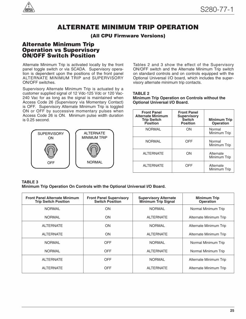
Alternate Minimum Trip is activated locally by the frontpanel toggle switch or via SCADA. Supervisory opera-tion is dependent upon the positions of the front panelALTERNATE MINIMUM TRIP and SUPERVISORYON/OFF switches.
Supervisory Alternate Minimum Trip is actuated by acustomer supplied signal of 12 Vdc-125 Vdc or 120 Vac-240 Vac for as long as the signal is maintained whenAccess Code 26 (Supervisory via Momentary Contact)is OFF. Supervisory Alternate Minimum Trip is toggledON or OFF by successive momentary pulses whenAccess Code 26 is ON. Minimum pulse width durationis 0.25 second.
Tables 2 and 3 show the effect of the SupervisoryON/OFF switch and the Alternate Minimum Trip switchon standard controls and on controls equipped with theOptional Universal I/O board, which includes the super-visory alternate minimum trip contacts.
ALTERNATE MINIMUM TRIP OPERATION(All CPU Firmware Versions)
SUPERVISORYON
OFF
ALTERNATEMINIMUM TRIP
NORMAL
TABLE 2Minimum Trip Operation on Controls without theOptional Universal I/O Board.
Front Panel Front PanelAlternate Minimum Supervisory
Trip Switch Switch Minimum TripPosition Position Operation
NORMAL ON NormalMinimum Trip
NORMAL OFF NormalMinimum Trip
ALTERNATE ON AlternateMinimum Trip
ALTERNATE OFF AlternateMinimum Trip
Front Panel Alternate Minimum Front Panel Supervisory Supervisory Alternate Minimum TripTrip Switch Position Switch Position Minimum Trip Signal Operation
NORMAL ON NORMAL Normal Minimum Trip
NORMAL ON ALTERNATE Alternate Minimum Trip
ALTERNATE ON NORMAL Alternate Minimum Trip
ALTERNATE ON ALTERNATE Alternate Minimum Trip
NORMAL OFF NORMAL Normal Minimum Trip
NORMAL OFF ALTERNATE Normal Minimum Trip
ALTERNATE OFF NORMAL Alternate Minimum Trip
ALTERNATE OFF ALTERNATE Alternate Minimum Trip
TABLE 3Minimum Trip Operation On Controls with the Optional Universal I/O Board.
Alternate Minimum TripOperation vs SupervisoryON/OFF Switch Position

26
Kyle Form 4C Microprocessor-Based Recloser Control Installation and Operation Instructions
Non-Reclosing is activated locally by the front panel tog-gle switch or via SCADA. Supervisory operation isdependent upon the positions of the front panel NON-RECLOSING and SUPERVISORY ON/OFF switches.
Supervisory Non-Reclosing is actuated by a customersupplied signal of 12 Vdc-125 Vdc or 120 Vac-240 Vacfor as long as the signal is maintained when AccessCode 26 (Supervisory via Momentary Contact) is OFF.Supervisory Non-Reclosing is toggled ON or OFF bysuccessive momentary pulses when Access Code 26 isON. Minimum pulse width duration is 0.25 second.
Tables 4 and 5 show the effect of the SupervisoryON/OFF switch and the Non-Reclosing switch on stan-dard controls and on controls equipped with the OptionalUniversal I/O board, which includes the supervisory non-reclosing contacts.
NON-RECLOSING OPERATION(All CPU Firmware Versions)
SUPERVISORYON
OFF
NONRECLOSING
NORMALRECLOSING
TABLE 4Reclosing Operation on Controls without theOptional Universal I/O Board.
Front Panel Front PanelNon-Reclosing Supervisory
Switch Switch ReclosingPosition Position Operation
NORMAL ON NormalRECLOSING Reclosing
NORMAL OFF NormalRECLOSING Reclosing
NON-RECLOSING ON Non-Reclosing
NON-RECLOSING OFF Non-Reclosing
Front Panel Non-Reclosing Front Panel Supervisory Supervisory ReclosingSwitch Position Switch Position Non-Reclosing Signal Operation
NORMAL RECLOSING ON NORMAL RECLOSING Normal Reclosing
NORMAL RECLOSING ON NON-RECLOSING Non-Reclosing
NON-RECLOSING ON NORMAL RECLOSING Non-Reclosing
NON-RECLOSING ON NON-RECLOSING Non-Reclosing
NORMAL RECLOSING OFF NORMAL RECLOSING Normal Reclosing
NORMAL RECLOSING OFF NON-RECLOSING Normal Reclosing
NON-RECLOSING OFF NORMAL RECLOSING Non-Reclosing
NON-RECLOSING OFF NON-RECLOSING Non-Reclosing
TABLE 5Reclosing Operation On Controls with the Optional Universal I/O Board.
Non-Reclosing Operation vsSupervisory ON/OFF SwitchPosition

27
S280-77-1!
SAFETYFOR LIFE
Ground-Trip Block is activated locally by the front paneltoggle switch or via SCADA. Supervisory operation isdependent upon the positions of the front panelGROUND TRIP BLOCK and SUPERVISORY ON/OFFswitches.
Supervisory Ground Trip Block is actuated by a cus-tomer supplied signal of 12 Vdc-125 Vdc or 120 Vac-240 Vac for as long as the signal is maintained whenAccess Code 26 (Supervisory via Momentary Contact)is OFF. Supervisory ground Trip Block is toggled ON orOFF by successive momentary pulses if Access Code26 is ON. Minimum pulse width duration is 0.25 second.
Tables 6 and 7 show the effect of the SupervisoryON/OFF switch and the Ground Trip Block switch onstandard controls and on controls equipped with theOptional Universal I/O board which include the Supervi-sory Ground Trip contacts.
GROUND TRIP BLOCK OPERATION(All CPU Firmware Versions)
SUPERVISORYON
OFF
GROUND TRIPBLOCK
GROUND TRIPNORMAL
TABLE 6Ground Trip Operation on Controls without theOptional Universal I/O Board.
Front Panel Front PanelGround Trip SupervisoryBlock Switch Switch Ground Trip
Position Position Operation
GROUND TRIP ON Ground TripNORMAL Normal
GROUND TRIP OFF Ground TripNORMAL Normal
GROUND TRIP ON Ground TripBLOCK Block
GROUND TRIP OFF Ground TripBLOCK Block
Front Panel Ground Trip Front Panel Supervisory Supervisory Ground Trip Ground TripBlock Switch Position Switch Position Block Signal Operation
GROUND TRIP NORMAL ON GROUND TRIP NORMAL Ground Trip Normal
GROUND TRIP NORMAL ON GROUND TRIP BLOCK Ground Trip Block
GROUND TRIP BLOCK ON GROUND TRIP NORMAL Ground Trip Block
GROUND TRIP BLOCK ON GROUND TRIP BLOCK Ground Trip Block
GROUND TRIP NORMAL OFF GROUND TRIP NORMAL Ground Trip Normal
GROUND TRIP NORMAL OFF GROUND TRIP BLOCK Ground Trip Normal
GROUND TRIP BLOCK OFF GROUND TRIP NORMAL Ground Trip Block
GROUND TRIP BLOCK OFF GROUND TRIP BLOCK Ground Trip Block
TABLE 7Ground Trip Operation On Controls with the Optional Universal I/O Board.
Ground Trip Block Operation vsSupervisory ON/OFF SwitchPosition

Kyle Form 4C Microprocessor-Based Recloser Control Installation and Operation Instructions
Optional Universal I/O BoardThe Optional Universal I/O Board is available for theForm 4C control to extend its supervisory operationcapabilities. The Optional I/O board includes contacts toprovide supervisory control and status indication of fouradditional control and recloser accessories, along withtargets.
The supervisory control functions require customer-pro-vided power of 120-240 Vac or 12-125 Vdc for operationand are controlled by the Supervisory ON/OFF switch.
Customer connections to the Optional Universal I/Oboard are made to the 30 position terminal strip shownin Figure 18, Detail A.
Supervisory status points for accessories available onCPU Firmware version 8.XX through 13.XX are locatedin either the OPT1 or OPT2 locations. Terminals 22through 24 comprise OPT2 and terminals 28 through 30comprise OPT1. Table 8 shows each accessory and itsterminal location based on the CPU firmware.
Note: Terminal 19 is the contact point for supervisory com-mand for OPT1. Terminal 20 is the contact point forsupervisory command for OPT2.
ACCESSORIES
Firmware Accessory CPU Firmware (Access Code 72) Protocol 2179
8.15 9.15 10.15 11.15 12.15 13.15
Hot Line Tag OPT2 OPT2 OPT2
Trip On TCC2 OPT1 OPT2 OPT2
Sensitive Ground/Earth Fault ON/OFF OPT1 OPT2 OPT1
Switch Mode OPT1 OPT1 OPT1
TABLE 8CPU firmware accessories.
28

S280-77-1!
SAFETYFOR LIFE
The Optional Universal l/O board also includes:
Ground Trip Block Status IndicatorThe Ground Trip Block Status indicator provides aclosed, dry contact to provide remote indication whenthe control is placed into the ground trip block modefrom either the front panel Ground Trip Block switch orthrough supervisory control.
Non-Reclosing Status IndicatorThe Non-Reclosing Status indicator provides a closed,dry contact to provide remote indication when the controlis placed into the non-reclosing mode from either thefront panel NON-RECLOSING switch or through supervi-sory control.
Alternate Minimum Trip StatusIndicatorAlternate Minimum Trip Status indicator provides aclosed, dry contact to provide remote indication whenthe control is placed into the alternate minimum tripmode from either the front panel ALTERNATE MINIMUMTRIP switch or through supervisory control.
Control Lockout Status IndicatorThe Control Lockout Status indicator provides a closed,dry contact to provide remote indication of control lockout.
Remote Fault Target IndicatorRemote Fault Target Indicator provides separate drycontacts for remote indication of phase targets for bush-ings 1-2, 3-4 and 5-6. If Sensitive Ground/Earth Fault isON, the contacts will indicate for phase, ground andSensitive Ground/Earth Faults.
Supervisory Ground Trip BlockSupervisory Ground Trip Block provides supervisoryoperation of ground trip block by a remote momentary ormaintained signal. Supervisory operation is dependentupon the positions of the front panel GROUND TRIPBLOCK and SUPERVISORY ON/OFF switches.Momentary (0.25 second minimum) or maintained signalmode is programmable using Access Code 26.
Supervisory Non-ReclosingSupervisory Non-Reclosing provides supervisory non-reclosing input by a remote momentary or maintainedsignal. Supervisory operation is dependent upon frontpanel NON-RECLOSING and SUPERVISORY ON/OFFswitch positions. Momentary (0.25 second minimum) ormaintained signal mode is programmable using AccessCode 26.
Supervisory Alternate Minimum TripSupervisory Alternate Minimum Trip provides selection ofalternate programmed values for phase and ground mini-mum trip. This feature is activated by a remote momen-tary or maintained signal. Supervisory operation isdependent upon front panel ALTERNATE MINIMUMTRIP and SUPERVISORY ON/OFF switch positions.Momentary (0.25 second minimum) or maintained signalmode is programmable using Access Code 26.
Supervisory TripSupervisory Trip provides the ability to trip the recloserfrom a remote signal. Normal reclosing operations willfollow. Operation is permitted only when the SUPERVI-SORY ON/OFF switch is ON. A momentary signal (min-imum of 0.25 second) is required for proper operation.
Load Tap Change Disable (LTCD)Status IndicatorLoad Tap Change Disable allows a regulator to ridethrough a multiple-shot recloser sequence without chang-ing taps in an attempt to react to the recloser sequence.Load Tap Change Disable provides a Form C status con-tact which is activated at a trip signal and will remainactive while in a reclosing sequence. The status contactresets when the control sequences to lockout or after thereset-after-reclose time delay elapses. The status contactis normally open and closes on an activated trip signal.
When a control is in SWITCH MODE (applicable to CPUFirmware version 8.XX, 11.XX, or 12.XX only), andsenses an overcurrent condition, the LTCD status con-tact is activated as long as the overcurrent conditionexists. Additionally, the LTCD status contact will remainactive for the period of time programmed in AccessCode 06 (Reset Time) fol lowing the overcurrentcondition.
29
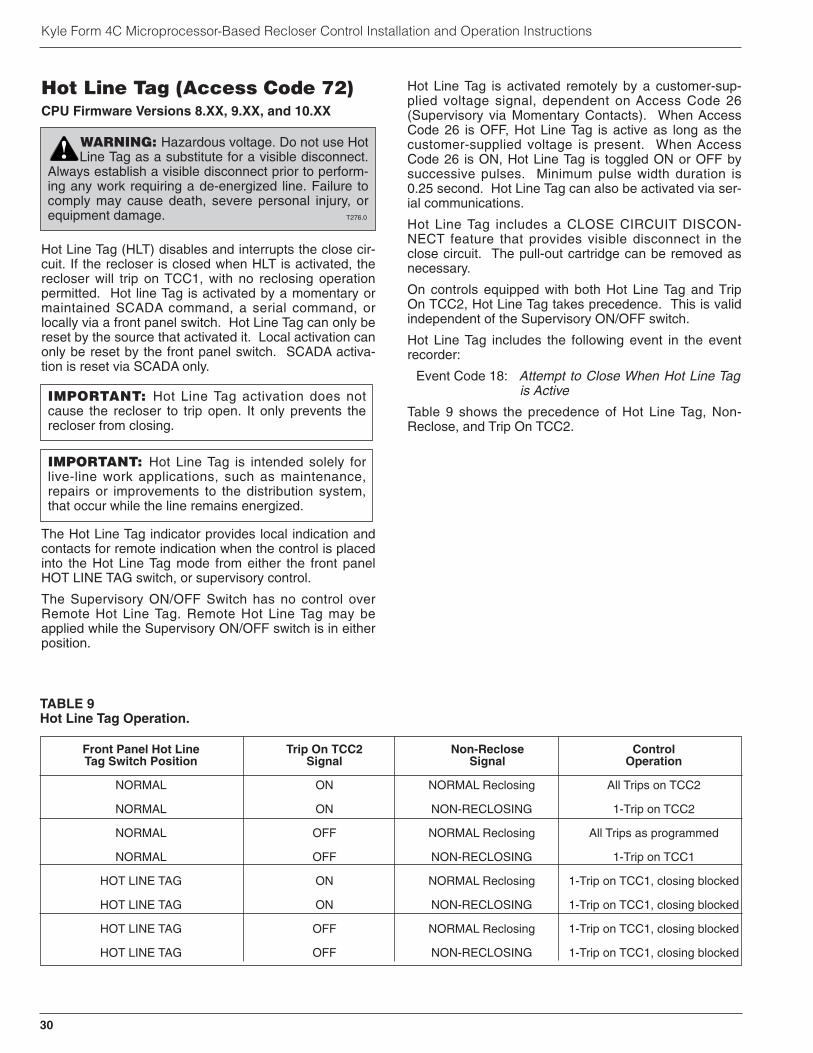
Kyle Form 4C Microprocessor-Based Recloser Control Installation and Operation Instructions
Hot Line Tag (Access Code 72)CPU Firmware Versions 8.XX, 9.XX, and 10.XX
Hot Line Tag (HLT) disables and interrupts the close cir-cuit. If the recloser is closed when HLT is activated, therecloser will trip on TCC1, with no reclosing operationpermitted. Hot line Tag is activated by a momentary ormaintained SCADA command, a serial command, orlocally via a front panel switch. Hot Line Tag can only bereset by the source that activated it. Local activation canonly be reset by the front panel switch. SCADA activa-tion is reset via SCADA only.
The Hot Line Tag indicator provides local indication andcontacts for remote indication when the control is placedinto the Hot Line Tag mode from either the front panelHOT LINE TAG switch, or supervisory control.
The Supervisory ON/OFF Switch has no control overRemote Hot Line Tag. Remote Hot Line Tag may beapplied while the Supervisory ON/OFF switch is in eitherposition.
Hot Line Tag is activated remotely by a customer-sup-plied voltage signal, dependent on Access Code 26(Supervisory via Momentary Contacts). When AccessCode 26 is OFF, Hot Line Tag is active as long as thecustomer-supplied voltage is present. When AccessCode 26 is ON, Hot Line Tag is toggled ON or OFF bysuccessive pulses. Minimum pulse width duration is0.25 second. Hot Line Tag can also be activated via ser-ial communications.
Hot Line Tag includes a CLOSE CIRCUIT DISCON-NECT feature that provides visible disconnect in theclose circuit. The pull-out cartridge can be removed asnecessary.
On controls equipped with both Hot Line Tag and TripOn TCC2, Hot Line Tag takes precedence. This is validindependent of the Supervisory ON/OFF switch.
Hot Line Tag includes the following event in the eventrecorder:
Event Code 18: Attempt to Close When Hot Line Tagis Active
Table 9 shows the precedence of Hot Line Tag, Non-Reclose, and Trip On TCC2.
Front Panel Hot Line Trip On TCC2 Non-Reclose ControlTag Switch Position Signal Signal Operation
NORMAL ON NORMAL Reclosing All Trips on TCC2
NORMAL ON NON-RECLOSING 1-Trip on TCC2
NORMAL OFF NORMAL Reclosing All Trips as programmed
NORMAL OFF NON-RECLOSING 1-Trip on TCC1
HOT LINE TAG ON NORMAL Reclosing 1-Trip on TCC1, closing blocked
HOT LINE TAG ON NON-RECLOSING 1-Trip on TCC1, closing blocked
HOT LINE TAG OFF NORMAL Reclosing 1-Trip on TCC1, closing blocked
HOT LINE TAG OFF NON-RECLOSING 1-Trip on TCC1, closing blocked
TABLE 9Hot Line Tag Operation.
30
WARNING: Hazardous voltage. Do not use HotLine Tag as a substitute for a visible disconnect.
Always establish a visible disconnect prior to perform-ing any work requiring a de-energized line. Failure tocomply may cause death, severe personal injury, orequipment damage. T276.0
!
IMPORTANT: Hot Line Tag is intended solely forlive-line work applications, such as maintenance,repairs or improvements to the distribution system,that occur while the line remains energized.
IMPORTANT: Hot Line Tag activation does notcause the recloser to trip open. It only prevents therecloser from closing.

S280-77-1!
SAFETYFOR LIFE
Testing the Hot Line Tag (HLT) StatusContactNote: Supervisory control must be disabled before testing.
1. Move the Hot Line Tag switch to the HOT LINE TAGposition.
2. Connect ohmmeter probes to terminals 22 and 23.The ohmmeter must indicate a closed contactbetween these terminals.
3. Connect ohmmeter probes to terminals 23 and 24.The ohmmeter must indicate an open contactbetween these terminals.
4. Move the Hot Line Tag switch to the NORMAL position.
5. Connect the ohmmeter probes to terminals 23 and24. The ohmmeter must indicate a closed contactbetween these terminals.
6. Connect the ohmmeter probes to terminals 22 and23. The ohmmeter must indicate an open contactacross these terminals.
CLOSE CIRCUIT
DISCONNECT
HOT LINE TAG
ON
HOT LINE TAG
NORMAL
22 23
NORMAL
HOT LINE TAG
NORMAL
HOT LINE TAG
OPT2*
24 22 23 24
*Applicable to CPU Firmware versions 8.XX, 9.XX, and 10.XX
31
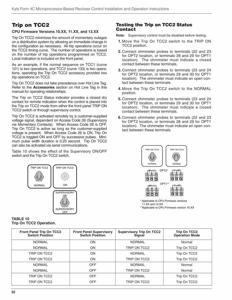
Kyle Form 4C Microprocessor-Based Recloser Control Installation and Operation Instructions
Trip on TCC2CPU Firmware Versions 10.XX, 11.XX, and 13.XX
Trip On TCC2 minimizes the amount of momentary outageson a distribution system by allowing an immediate change inthe configuration as necessary. All trip operations occur onthe TCC2 timing curve. The number of operations is basedon the number of trip operations programmed on TCC2.Local indication is included on the front panel.
As an example, if the normal sequence on TCC1 (curve101) is two operations, and TCC2 (curve 133) is two opera-tions, operating the Trip On TCC2 accessory provides twotrip operations on TCC2.
Trip On TCC2 does not take precedence over Hot Line Tag.Refer to the Accessories section on Hot Line Tag in thismanual for operating relationships.
The Trip on TCC2 Status indicator provides a closed drycontact for remote indication when the control is placed intothe Trip on TCC2 mode from either the front panel TRIP ONTCC2 switch or through supervisory control.
Trip On TCC2 is activated remotely by a customer-suppliedvoltage signal, dependent on Access Code 26 (Supervisoryvia Momentary Contacts). When Access Code 26 is OFF,Trip On TCC2 is active as long as the customer-suppliedvoltage is present. When Access Code 26 is ON, Trip OnTCC2 is toggled ON and OFF by successive pulses. Mini-mum pulse width duration is 0.25 second. Trip On TCC2can also be activated via serial communications.
Table 10 shows the effect of the Supervisory ON/OFFswitch and the Trip On TCC2 switch.
Testing the Trip on TCC2 StatusContactNote: Supervisory control must be disabled before testing.
1. Move the Trip On TCC2 switch to the TRIP ONTCC2 position.
2. Connect ohmmeter probes to terminals (22 and 23for OPT2 location, or terminals 28 and 29 for OPT1location). The ohmmeter must indicate a closedcontact between these terminals.
3. Connect ohmmeter probes to terminals (23 and 24for OPT2 location, or terminals 29 and 30 for OPT1location). The ohmmeter must indicate an open con-tact between these terminals.
4. Move the Trip On TCC2 switch to the NORMALposition.
5. Connect ohmmeter probes to terminals (23 and 24for OPT2 location, or terminals 29 and 30 for OPT1location). The ohmmeter must indicate a closedcontact between these terminals.
6. Connect ohmmeter probes to terminals (22 and 23for OPT2 location, or terminals 28 and 29 for OPT1location). The ohmmeter must indicate an open con-tact between these terminals.
32
TRIP ON TCC2
ON
TRIP ON TCC2
NORMAL
SUPERVISORYON
SUPERVISORYOFF
NORMAL
TRIP ON TCC2
NORMAL
TRIP ON TCC2
OPT2*
OPT1**
22 23 24 22 23 24
28 29 30 28 29 30
* Applicable to CPU Firmware versions 11.XX and 13.XX
**Applicable to CPU Firmware version 10.XX
Front Panel Trip On TCC2 Front Panel Supervisory Supervisory Trip On TCC2 Trip On TCC2Switch Position Switch Position Signal Operation Mode
NORMAL ON NORMAL Normal
NORMAL ON TRIP ON TCC2 Trip On TCC2
TRIP ON TCC2 ON NORMAL Trip On TCC2
TRIP ON TCC2 ON TRIP ON TCC2 Trip On TCC2
NORMAL OFF NORMAL Normal
NORMAL OFF TRIP ON TCC2 Normal
TRIP ON TCC2 OFF NORMAL Trip On TCC2
TRIP ON TCC2 OFF TRIP ON TCC2 Trip On TCC2
TABLE 10Trip On TCC2 Operation.

S280-77-1!
SAFETYFOR LIFE
33
Sensitive Ground/Earth Fault(SGF) ON/OFFCPU Firmware Versions 9.XX, 12.XX, and 13.XX
Sensitive Ground/Earth Fault (SGF) ON/OFF provides thecapability to separate the activation of sensitiveground/earth fault from normal ground sensing. If GroundTrip is activated, SGF may or may not be activated,depending on the specific application. If Ground Trip isblocked, SGF is also blocked.
Sensitive Ground/Earth Fault is activated remotely by acustomer-supplied voltage signal, dependent on AccessCode 26 (Supervisory via Momentary Contacts). WhenAccess Code 26 is OFF, SGF is active as long as the cus-tomer-supplied voltage is present. When Access Code 26is ON, SGF is toggled ON and OFF by successive pulses.Minimum pulse width duration is 0.25 second. SGF canalso be activated via serial communications.
Note: Access Code 120 is an enable/disable feature for SGF. IfAccess Code 120 is OFF, SGF is completely disabled(blocked).
Note: Setting SGF minimum trip or SGF alternate minimumtrip to 100% disables SGF, regardless of the positionof the toggle switch.
Table 11 shows the effect of the Supervisory ON/OFFswitch and the SGF switch.
Testing the SGF Status ContactNote: Supervisory control must be disabled before testing.
1. Move the SGF switch to the ON position.
2. Connect ohmmeter probes to terminals (22 and 23 forOPT2 location, or 28 and 29 for OPT1 location). Theohmmeter must indicate a closed contact betweenthese terminals.
3. Connect ohmmeter probes to terminals (23 and 24 forOPT2 location, or 29 and 30 for OPT1 location). Theohmmeter must indicate an open contact betweenthese terminals.
4. Move the SGF switch to the OFF position.
5. Connect ohmmeter probes to terminals (23 and 24 forOPT2 location, or 29 and 30 for OPT1 location). Theohmmeter must indicate a closed contact betweenthese terminals.
6. Connect ohmmeter probes to terminals (22 and 23 forOPT2 location, or 28 and 29 for OPT1 location). Theohmmeter must indicate an open contact betweenthese terminals.
SGF
ON
SGFON
OFF
SUPERVISORYON
SUPERVISORYOFF
Front Panel SGF Front Panel Supervisory Supervisory SGF Keypad SGFSwitch Position Switch Position Signal (Access Code 120) Operation Mode
ON ON ON ON ONON ON ON OFF OFFON ON OFF ON ONON ON OFF OFF OFFON OFF ON ON ONON OFF ON OFF OFFON OFF OFF ON ONON OFF OFF OFF OFFOFF ON ON ON ONOFF ON ON OFF OFFOFF ON OFF ON OFFOFF ON OFF OFF OFFOFF OFF ON ON OFFOFF OFF ON OFF OFFOFF OFF OFF ON OFFOFF OFF OFF OFF OFF
TABLE 11Sensitive Ground/Earth Fault (SGF) ON/OFF Operation.
OFF
SGFON
OFF
SGFON
OPT2*
OPT1**
22 23 24 22 23 24
28 29 30 28 29 30
* Applicable to CPU Firmware version 12.XX**Applicable to CPU Firmware versions 9.XX
and 13.XX

Kyle Form 4C Microprocessor-Based Recloser Control Installation and Operation Instructions
Switch ModeCPU Firmware Versions 8.XX, 11.XX, and 12.XX
With the Switch Mode accessory, the Form 4C reclosercontrol becomes a switch control providing indication ofovercurrent conditions without issuing a overcurrent tripsignal.
The Switch Mode accessory is a non-tripping, fault indi-cation state initiated from the front panel as well as seri-al or discrete SCADA.
Switch Mode is activated remotely by a customer-suppliedvoltage signal, dependent on Access Code 26 (Superviso-ry via Momentary Contacts). When Access Code 26 isOFF, Switch Mode is active as long as the customer-sup-plied voltage is present. When Access Code 26 is ON,Switch Mode is toggled ON and OFF by successive puls-es. Minimum pulse width duration is 0.25 second. SwitchMode can also be activated via serial communications.
The Switch Mode status indicator provides a closed drycontact for remote indication when the control is placedinto the switch mode from either the front panelRECLOSER MODE/SWITCH MODE switch or throughsupervisory control.
Included as part of the switch mode are the followingevents in the event recorder:
Event Type 14: Fault Target Event - Used in theSwitch Mode when fault exceeds thetime-current curve.
Event Type 15: Switch Mode - Records the currents,date, and time when the control is setto Switch Mode.
Event Type 16: Recloser Mode - Records the cur-rents, date, and time when the con-trol is set to Recloser Mode.
Three access codes have been developed to set bothphase and ground target sensing for normal and alter-nate target sensing, and the selection of TCC1 andTCC2. The TCC modifiers are available in both therecloser or switch mode. Refer to Access Codes 190through 192 in Service Information S280-77-4, Form 4CMicroprocessor-Based Recloser Control ProgrammingGuide.
The auto reset for the target indicators is controlled byAccess Code 21 and the reset time is programmable viaAccess Code 6. They can also be reset via serial com-munications, or via the Optional Universal I/O board uti-lizing the Supervisory Non-Reclose contact.
The Sequence Position (Access Code 38) remains at “1”while in the Switch Mode during a target operation. Thesequence position resets to zero upon reset.
Note: The Non-Reclose status output contact is disabledwhile the control is in the Switch Mode. The Non-Reclose function reverts to its previous state when thecontrol is placed in the Recloser mode.
34
SWITCH MODE
ON
SWITCH MODE(AUTO TRIP OFF)
RECLOSER MODE(AUTO TRIP ON)
SUPERVISORYON
SUPERVISORYOFF
Front Panel Front Panel Supervisory SupervisorySwitch Position ON/OFF Switch Position Position Control Mode
RECLOSER MODE ON RECLOSER MODE Recloser Mode
RECLOSER MODE ON SWITCH MODE Switch Mode
SWITCH MODE ON RECLOSER MODE Switch Mode
SWITCH MODE ON SWITCH MODE Switch Mode
RECLOSER MODE OFF RECLOSER MODE Recloser Mode
RECLOSER MODE OFF SWITCH MODE Recloser Mode
SWITCH MODE OFF RECLOSER MODE Switch Mode
SWITCH MODE OFF SWITCH MODE Switch Mode
TABLE 12Switch Mode Operation On Controls with the Optional Universal I/O Board.
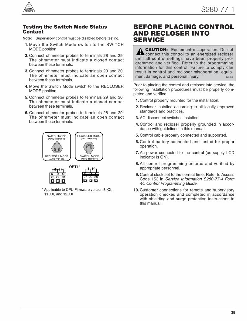
S280-77-1!
SAFETYFOR LIFE
Testing the Switch Mode StatusContactNote: Supervisory control must be disabled before testing.
1. Move the Switch Mode switch to the SWITCHMODE position.
2. Connect ohmmeter probes to terminals 28 and 29.The ohmmeter must indicate a closed contactbetween these terminals.
3. Connect ohmmeter probes to terminals 29 and 30.The ohmmeter must indicate an open contactbetween these terminals.
4. Move the Switch Mode switch to the RECLOSERMODE position.
5. Connect ohmmeter probes to terminals 29 and 30.The ohmmeter must indicate a closed contactbetween these terminals.
6. Connect ohmmeter probes to terminals 28 and 29.The ohmmeter must indicate an open contactbetween these terminals.
Prior to placing the control and recloser into service, thefollowing installation procedures must be properly com-pleted and verified.
1. Control properly mounted for the installation.
2. Recloser installed according to all locally approvedstandards and practices.
3. AC disconnect switches installed.
4. Control and recloser properly grounded in accor-dance with guidelines in this manual.
5. Control cable properly connected and supported.
6. Control battery connected and tested for properoperation.
7. Ac power connected to the control (ac supply LCDindicator is ON).
8. All control programming entered and verified byappropriate personnel.
9. Control clock set to the correct time. Refer to AccessCode 153 in Service Information S280-77-4 Form4C Control Programming Guide.
10. Customer connections for remote and supervisoryoperation checked and completed in accordancewith shielding and surge protection instructions inthis manual.
BEFORE PLACING CONTROLAND RECLOSER INTOSERVICE
RECLOSER MODE(AUTO TRIP ON)
RECLOSER MODE(AUTO TRIP ON)
SWITCH MODE(AUTO TRIP OFF)
SWITCH MODE(AUTO TRIP OFF)
OPT1*
28 29 30 28 29 30
* Applicable to CPU Firmware version 8.XX, 11.XX, and 12.XX
CAUTION: Equipment misoperation. Do notconnect this control to an energized recloser
until all control settings have been properly pro-grammed and verified. Refer to the programminginformation for this control. Failure to comply canresult in control and recloser misoperation, equip-ment damage, and personal injury. G110.3
!
35
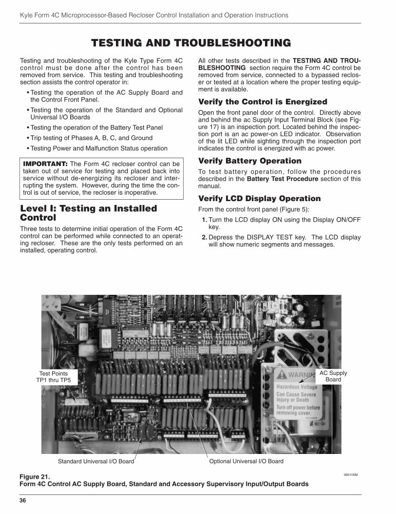
36
Kyle Form 4C Microprocessor-Based Recloser Control Installation and Operation Instructions
Testing and troubleshooting of the Kyle Type Form 4Ccontrol must be done after the control has beenremoved from service. This testing and troubleshootingsection assists the control operator in:
• Testing the operation of the AC Supply Board andthe Control Front Panel.
• Testing the operation of the Standard and OptionalUniversal I/O Boards
• Testing the operation of the Battery Test Panel
• Trip testing of Phases A, B, C, and Ground
• Testing Power and Malfunction Status operation
Level I: Testing an InstalledControlThree tests to determine initial operation of the Form 4Ccontrol can be performed while connected to an operat-ing recloser. These are the only tests performed on aninstalled, operating control.
All other tests described in the TESTING AND TROU-BLESHOOTING section require the Form 4C control beremoved from service, connected to a bypassed reclos-er or tested at a location where the proper testing equip-ment is available.
Verify the Control is EnergizedOpen the front panel door of the control. Directly aboveand behind the ac Supply Input Terminal Block (see Fig-ure 17) is an inspection port. Located behind the inspec-tion port is an ac power-on LED indicator. Observationof the lit LED while sighting through the inspection portindicates the control is energized with ac power.
Verify Battery OperationTo test battery operation, fol low the proceduresdescribed in the Battery Test Procedure section of thismanual.
Verify LCD Display OperationFrom the control front panel (Figure 5):
1. Turn the LCD display ON using the Display ON/OFFkey.
2. Depress the DISPLAY TEST key. The LCD displaywill show numeric segments and messages.
TESTING AND TROUBLESHOOTING
IMPORTANT: The Form 4C recloser control can betaken out of service for testing and placed back intoservice without de-energizing its recloser and inter-rupting the system. However, during the time the con-trol is out of service, the recloser is inoperative.
Figure 21.Form 4C Control AC Supply Board, Standard and Accessory Supervisory Input/Output Boards
99011KM
Optional Universal I/O BoardStandard Universal I/O Board
Test PointsTP1 thru TP5
AC SupplyBoard
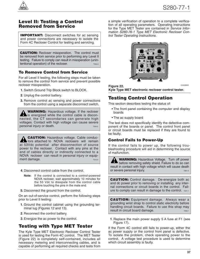
S280-77-1!
SAFETYFOR LIFE
Level II: Testing a ControlRemoved from Service
To Remove Control from ServiceFor all Level II testing, the following steps must be takento remove the control from service and prevent possiblerecloser misoperation.
1. Switch Ground Trip Block switch to BLOCK.
2. Unplug the control battery.
3. Remove control ac sensing and power connectionsfrom the control using a separate disconnect switch.
4. Disconnect control cable from the control.
Note: If the control is connected to a control-poweredNOVA recloser, wait approximately 10 minutes forthe 53 Vdc to dissipate from the control cablebefore touching the pins in the male end.
5. Disconnect the ground from the control.
On an out-of-service control, perform the following stepsprior to Level II testing:
1. Ground the control cabinet using the grounding ter-minal lug (Figures 12 and 13).
2. Reconnect the control battery.
3. Energize the ac power to the control.
Testing with Type MET TesterThe Kyle Type MET Electronic Recloser Control Testeris used for testing the Form 4C control. The MET Tester(Figure 22) is completely self-contained, includes allnecessary metering and interconnecting cables, and iscapable of performing all required checks and tests from
a simple verification of operation to a complete verifica-tion of all operating parameters. Operating instructionsfor the Type MET Tester are contained in Service Infor-mation S280-76-1 Type MET Electronic Recloser Con-trol Tester Operating Instructions.
Testing Control OperationThis section describes testing the status of:
• The front panel containing the computer and displayboards
• The ac supply board
The test does not specifically identify the defective com-ponent of the boards or panel. The control front panelor circuit boards must be replaced if they are found tobe faulty.
Control Fails to Power-UpIf the control fails to power up, the following trou-bleshooting procedure will aid in determining the sourceof malfunction.
1. Replace the main power supply 5 A fuse at F1 (seeFigure 17).
If the Form 4C control still fails to power-up, either theac power supply or the control front panel is defective.To isolate the problem, check operating power to thecontrol. A voltage test procedure is used to determinewhich circuit assembly is faulty.
Figure 22.Kyle Type MET electronic recloser control tester.
010028KM
CAUTION: Control damage. De-energize both acand dc power prior to removing or installing any inter-nal connections or circuit boards in the control. Fail-ure to comply can result in damage to the control. T241.1
CAUTION: Recloser misoperation. The control mustbe removed from service prior to performing any Level IItesting. Failure to comply can result in misoperation (unin-tentional operation) of the recloser. T250.0
CAUTION: Equipment damage. Always wear agrounding wrist strap to control static electricity beforehandling circuit boards. Failure to use this strap mayresult in circuit board damage. T253.1
WARNING: Hazardous Voltage. Turn off powerbefore removing safety shield. Failure to do so can
result in contact with high voltage which will cause deathor severe personal injury. T261.0
37
!
IMPORTANT: Disconnect switches for ac sensingand power connections are necessary to isolate theForm 4C Recloser Control for testing and servicing.
WARNING: Hazardous voltage. If the recloseris energized while the control cable is discon-
nected, the CT secondaries can generate highvoltages. Contact with high voltage can cause severepersonal injury or death. T204.2
!
CAUTION: Hazardous voltage. Cable conduc-tors attached to NOVA reclosers will remain
at 53Vdc potential after disconnection of sourcepower to the recloser. Contact with any pins at theend of cables directly or indirectly connected to aNOVA recloser can result in personal injury or equip-ment damage. T312.0
!

38
Kyle Form 4C Microprocessor-Based Recloser Control Installation and Operation Instructions
Terminal P11, located on the ac supply board, (Figure 23)contains three test points to verify the status of theboard. The proper voltage across each of the three testpoints of P11 is listed below:
Pin 1 (Black wire) Zero (battery ground point)
Pin 3 (Blue wire) >25 Vdc
Pin 4 (Red wire) 24.0 Vdc
To test the voltages of P11 test points:
Pin 1
1. Using a digital multimeter, place the ground probeagainst the aluminum plate of the back panel of thecontrol.
Note: Keep the ground probe in contact with the alu-minum plate for all three dc voltage measurements.
2. Place the positive probe into the pin 1 location(Figure 24).
If Pin 1 does not read zero, the ac supply board isdefective and must be replaced.
Pin 3
3. Disconnect the control battery.
4. With the ground probe against the aluminum plate,place the positive probe into the pin 3 location.
If pin 3 does not measure approximately >25 Vdc, theac supply board is defective and must be replaced.
Pin 4
The computer and display boards, located in the controlfront panel, receive dc power from terminal P11-Pin 4(Red wire). A short circuit in the computer board cancause pin 4 to read a voltage lower than 24 Vdc.
If Pin 4 of P11 is not 24 Vdc, with the control battery dis-connected, follow the instructions below:
5. Disconnect ac power to the control.
6. Disconnect terminal P12 located at the top of the acsupply board (Figure 23).
7. Reconnect ac power.
8. Using a digital multimeter, place the ground probeagainst the aluminum plate of the back panel of thecontrol.
9. Place the positive probe into the Pin 4 location ofP11 (Figure 24).
If the power supply measures 24 Vdc with terminal P12disconnected, the computer board is defective and thecontrol front panel must be replaced.
If the power supply is less than 24 Vdc with terminal P12disconnected, the power supply board is defective andmust be replaced.
The computer board and the display board are locatedunder an aluminum cover on the inside front panel of thecontrol.
P11
Pin 1 (Black)
Pin 3 (Blue)Pin 4 (Red)
Digital MultimeterProbe
Figure 24.Testing voltage of P11-Pin 4 on the AC Power Supplyboard.
IMPORTANT: These boards must have compatiblesoftware versions to operate properly. Therefore, theentire front panel must be replaced if either the com-puter or display boards is defective. Contact yourCooper Power Systems representative for replace-ment information.
Figure 23.Upper portion of AC Power Supply Board.(Automation Power Supply shown).
99014KM
P12
P11
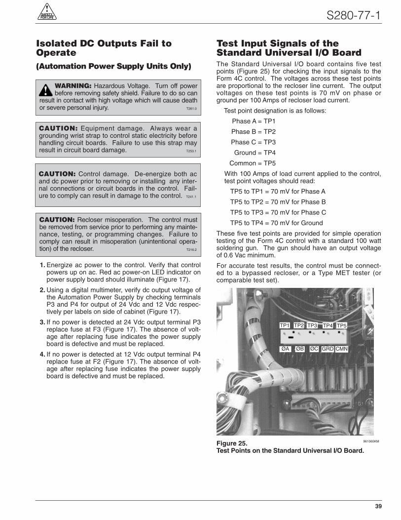
S280-77-1!
SAFETYFOR LIFE
Isolated DC Outputs Fail toOperate(Automation Power Supply Units Only)
1. Energize ac power to the control. Verify that controlpowers up on ac. Red ac power-on LED indicator onpower supply board should illuminate (Figure 17).
2. Using a digital multimeter, verify dc output voltage ofthe Automation Power Supply by checking terminalsP3 and P4 for output of 24 Vdc and 12 Vdc respec-tively per labels on side of cabinet (Figure 17).
3. If no power is detected at 24 Vdc output terminal P3replace fuse at F3 (Figure 17). The absence of volt-age after replacing fuse indicates the power supplyboard is defective and must be replaced.
4. If no power is detected at 12 Vdc output terminal P4replace fuse at F2 (Figure 17). The absence of volt-age after replacing fuse indicates the power supplyboard is defective and must be replaced.
Test Input Signals of theStandard Universal I/O BoardThe Standard Universal I/O board contains five testpoints (Figure 25) for checking the input signals to theForm 4C control. The voltages across these test pointsare proportional to the recloser line current. The outputvoltages on these test points is 70 mV on phase orground per 100 Amps of recloser load current.
Test point designation is as follows:
Phase A = TP1
Phase B = TP2
Phase C = TP3
Ground = TP4
Common = TP5
With 100 Amps of load current applied to the control,test point voltages should read:
TP5 to TP1 = 70 mV for Phase A
TP5 to TP2 = 70 mV for Phase B
TP5 to TP3 = 70 mV for Phase C
TP5 to TP4 = 70 mV for Ground
These five test points are provided for simple operationtesting of the Form 4C control with a standard 100 wattsoldering gun. The gun should have an output voltageof 0.6 Vac minimum.
For accurate test results, the control must be connect-ed to a bypassed recloser, or a Type MET tester (orcomparable test set).
Figure 25.Test Points on the Standard Universal I/O Board.
961065KM
TP1 TP2 TP3 TP4 TP5
ØA ØB ØC GRD CMN
CAUTION: Equipment damage. Always wear agrounding wrist strap to control static electricity beforehandling circuit boards. Failure to use this strap mayresult in circuit board damage. T253.1
CAUTION: Recloser misoperation. The control mustbe removed from service prior to performing any mainte-nance, testing, or programming changes. Failure tocomply can result in misoperation (unintentional opera-tion) of the recloser. T216.2
CAUTION: Control damage. De-energize both acand dc power prior to removing or installing any inter-nal connections or circuit boards in the control. Fail-ure to comply can result in damage to the control. T241.1
WARNING: Hazardous Voltage. Turn off powerbefore removing safety shield. Failure to do so can
result in contact with high voltage which will cause deathor severe personal injury. T261.0
!
39
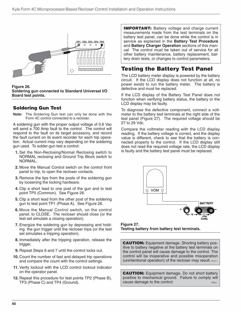
Kyle Form 4C Microprocessor-Based Recloser Control Installation and Operation Instructions
Soldering Gun TestNote: The Soldering Gun test can only be done with the
Form 4C control connected to a recloser.
A soldering gun with the proper output voltage of 0.6 Vacwill send a 700 Amp fault to the control. The control willrespond to the fault on its target accessory, and recordthe fault current on its event recorder for each trip opera-tion. Actual current may vary depending on the solderinggun used. To solder-gun test a control:
1. Set the Non-Reclosing/Normal Reclosing switch toNORMAL reclosing and Ground Trip Block switch toNORMAL.
2. Move the Manual Control switch on the control frontpanel to trip, to open the recloser contacts.
3. Remove the tips from the posts of the soldering gunby loosening the locking hardware.
4. Clip a short lead to one post of the gun and to testpoint TP5 (Common). See Figure 26.
5. Clip a short lead from the other post of the solderinggun to test point TP1 (Phase A). See Figure 26.
6. Move the Manual Control switch, on the controlpanel, to CLOSE. The recloser should close (or thetest set simulate a closing operation).
7. Energize the soldering gun by depressing and hold-ing the gun trigger until the recloser trips (or the testset simulates a tripping operation).
8. Immediately after the tripping operation, release thetrigger.
9. Repeat Steps 6 and 7 until the control locks out.
10. Count the number of fast and delayed trip operationsand compare the count with the control settings.
11. Verify lockout with the LCD control lockout indicatoron the operator panel.
12. Repeat this procedure for test points TP2 (Phase B),TP3 (Phase C) and TP4 (Ground).
Testing the Battery Test PanelThe LCD battery meter display is powered by the batterycircuit. If the LCD display does not function at all, nopower exists to run the battery meter. The battery isdefective and must be replaced.
If the LCD display of the Battery Test Panel does notfunction when verifying battery status, the battery or theLCD display may be faulty.
To diagnose the defective component, connect a volt-meter to the battery test terminals at the right side of thetest panel (Figure 27). The required voltage should be27 to 29 Vdc.
Compare the voltmeter reading with the LCD displayreading. If the battery voltage is correct, and the displayvalue is different, check to see that the battery is con-nected properly to the control. If the LCD display stilldoes not read the required voltage rate, the LCD displayis faulty and the battery test panel must be replaced.
Figure 27.Testing battery from battery test terminals.
VOM
IMPORTANT: Battery voltage and charge currentmeasurements made from the test terminals on thebattery test panel, can be done while the control is inservice as explained in the Battery Test Procedureand Battery Charger Operation sections of this man-ual The control must be taken out of service for allother battery maintenance, battery replacement, bat-tery drain tests, or changes to control parameters.
CAUTION: Equipment damage. Shorting battery pos-itive to battery negative at the battery test terminals onthe control panel will cause damage to the control. Thecontrol will be inoperative and possible misoperation(unintentional operation) of the recloser may result. T214.1
CAUTION: Equipment damage. Do not short batterypositive to mechanical ground. Failure to comply willcause damage to the control. T256.1
TP1 TP2 TP3 TP4 TP5
Figure 26.Soldering gun connected to Standard Universal I/OBoard test points.
40
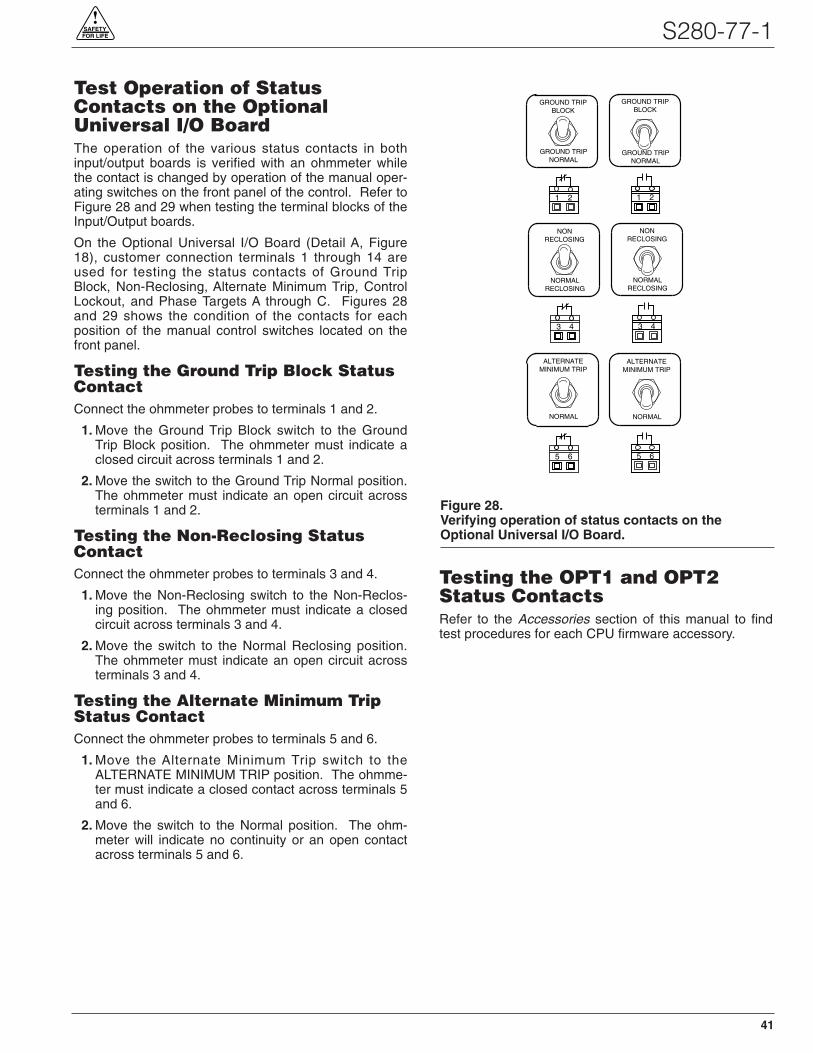
Test Operation of StatusContacts on the OptionalUniversal I/O BoardThe operation of the various status contacts in bothinput/output boards is verified with an ohmmeter whilethe contact is changed by operation of the manual oper-ating switches on the front panel of the control. Refer toFigure 28 and 29 when testing the terminal blocks of theInput/Output boards.
On the Optional Universal I/O Board (Detail A, Figure18), customer connection terminals 1 through 14 areused for testing the status contacts of Ground TripBlock, Non-Reclosing, Alternate Minimum Trip, ControlLockout, and Phase Targets A through C. Figures 28and 29 shows the condition of the contacts for eachposition of the manual control switches located on thefront panel.
Testing the Ground Trip Block StatusContactConnect the ohmmeter probes to terminals 1 and 2.
1. Move the Ground Trip Block switch to the GroundTrip Block position. The ohmmeter must indicate aclosed circuit across terminals 1 and 2.
2. Move the switch to the Ground Trip Normal position.The ohmmeter must indicate an open circuit acrossterminals 1 and 2.
Testing the Non-Reclosing StatusContactConnect the ohmmeter probes to terminals 3 and 4.
1. Move the Non-Reclosing switch to the Non-Reclos-ing position. The ohmmeter must indicate a closedcircuit across terminals 3 and 4.
2. Move the switch to the Normal Reclosing position.The ohmmeter must indicate an open circuit acrossterminals 3 and 4.
Testing the Alternate Minimum TripStatus ContactConnect the ohmmeter probes to terminals 5 and 6.
1. Move the Alternate Minimum Trip switch to theALTERNATE MINIMUM TRIP position. The ohmme-ter must indicate a closed contact across terminals 5and 6.
2. Move the switch to the Normal position. The ohm-meter will indicate no continuity or an open contactacross terminals 5 and 6.
Testing the OPT1 and OPT2Status ContactsRefer to the Accessories section of this manual to findtest procedures for each CPU firmware accessory.
GROUND TRIPBLOCK
1 2
GROUND TRIPNORMAL
GROUND TRIPBLOCK
GROUND TRIPNORMAL
1 2
NONRECLOSING
3 4
NORMALRECLOSING
3 4
NONRECLOSING
NORMALRECLOSING
ALTERNATEMINIMUM TRIP
5 6
NORMAL
5 6
ALTERNATEMINIMUM TRIP
NORMAL
Figure 28.Verifying operation of status contacts on theOptional Universal I/O Board.
41
S280-77-1!
SAFETYFOR LIFE
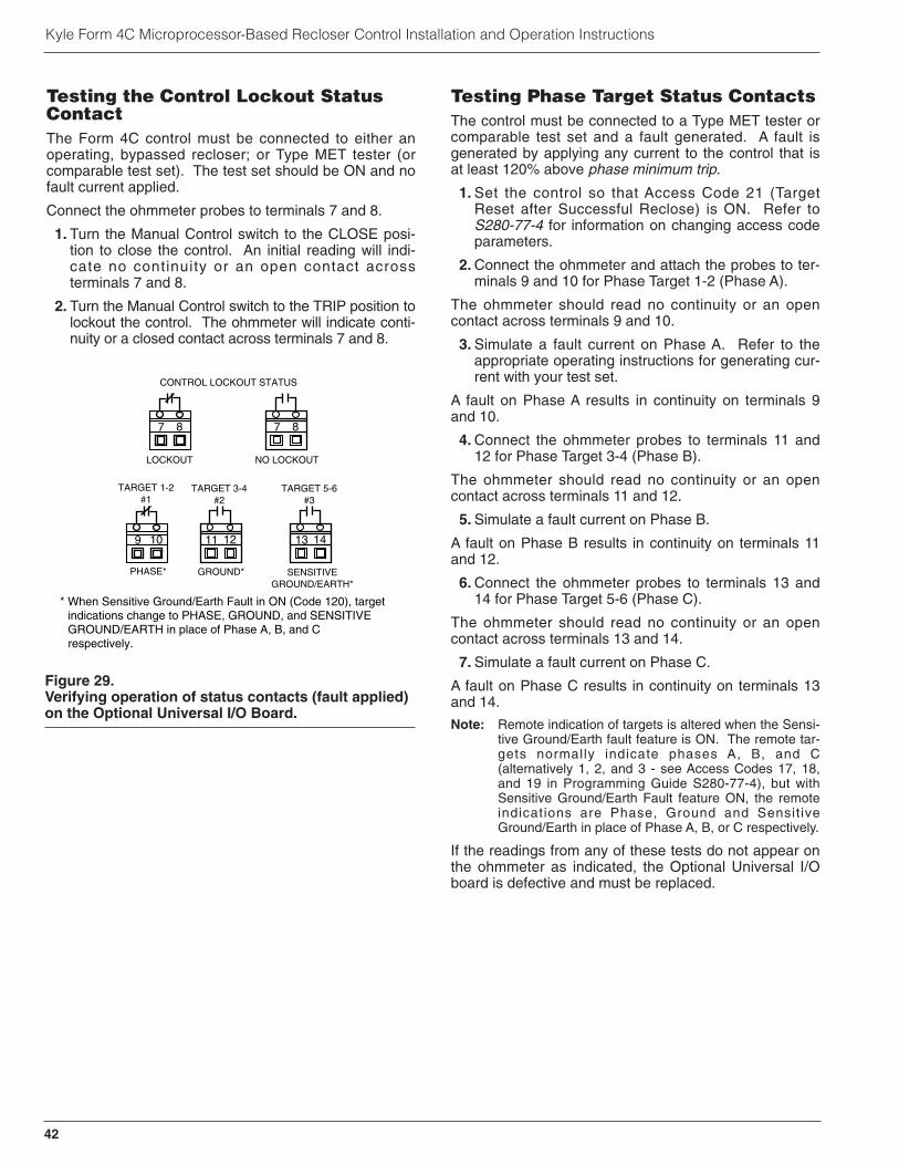
Kyle Form 4C Microprocessor-Based Recloser Control Installation and Operation Instructions
Testing the Control Lockout StatusContactThe Form 4C control must be connected to either anoperating, bypassed recloser; or Type MET tester (orcomparable test set). The test set should be ON and nofault current applied.
Connect the ohmmeter probes to terminals 7 and 8.
1. Turn the Manual Control switch to the CLOSE posi-tion to close the control. An initial reading will indi-cate no continuity or an open contact acrossterminals 7 and 8.
2. Turn the Manual Control switch to the TRIP position tolockout the control. The ohmmeter will indicate conti-nuity or a closed contact across terminals 7 and 8.
Testing Phase Target Status ContactsThe control must be connected to a Type MET tester orcomparable test set and a fault generated. A fault isgenerated by applying any current to the control that isat least 120% above phase minimum trip.
1. Set the control so that Access Code 21 (TargetReset after Successful Reclose) is ON. Refer toS280-77-4 for information on changing access codeparameters.
2. Connect the ohmmeter and attach the probes to ter-minals 9 and 10 for Phase Target 1-2 (Phase A).
The ohmmeter should read no continuity or an opencontact across terminals 9 and 10.
3. Simulate a fault current on Phase A. Refer to theappropriate operating instructions for generating cur-rent with your test set.
A fault on Phase A results in continuity on terminals 9and 10.
4. Connect the ohmmeter probes to terminals 11 and12 for Phase Target 3-4 (Phase B).
The ohmmeter should read no continuity or an opencontact across terminals 11 and 12.
5. Simulate a fault current on Phase B.
A fault on Phase B results in continuity on terminals 11and 12.
6. Connect the ohmmeter probes to terminals 13 and14 for Phase Target 5-6 (Phase C).
The ohmmeter should read no continuity or an opencontact across terminals 13 and 14.
7. Simulate a fault current on Phase C.
A fault on Phase C results in continuity on terminals 13and 14.
Note: Remote indication of targets is altered when the Sensi-tive Ground/Earth fault feature is ON. The remote tar-gets normally indicate phases A, B, and C(alternatively 1, 2, and 3 - see Access Codes 17, 18,and 19 in Programming Guide S280-77-4), but withSensitive Ground/Earth Fault feature ON, the remoteindications are Phase, Ground and Sensit iveGround/Earth in place of Phase A, B, or C respectively.
If the readings from any of these tests do not appear onthe ohmmeter as indicated, the Optional Universal I/Oboard is defective and must be replaced.
CONTROL LOCKOUT STATUS
9 10
TARGET 1-2#1
7 8
LOCKOUT
7 8
NO LOCKOUT
11 12
TARGET 3-4#2
13 14
TARGET 5-6#3
PHASE* GROUND* SENSITIVEGROUND/EARTH*
* When Sensitive Ground/Earth Fault in ON (Code 120), target indications change to PHASE, GROUND, and SENSITIVE GROUND/EARTH in place of Phase A, B, and C respectively.
Figure 29.Verifying operation of status contacts (fault applied)on the Optional Universal I/O Board.
42

S280-77-1!
SAFETYFOR LIFE
Test Operation of StatusContacts on the StandardUniversal I/O BoardOn the Standard Universal I/O board, customer connec-tion terminals 5 through 15 are for testing the status con-tacts of the Supervisory Switch and recloser, as well aspower and malfunction status. Figure 30 shows the con-dition of the contacts of each function.
To test the Supervisory Switch status contacts, con-nect the ohmmeter and attach the black and red probesto terminals 5 and 6 on the Standard Universal I/OBoard.
1. Move the Supervisory switch to the ON position.The ohmmeter will indicate continuity or a closedcontact.
2. Move the switch to the OFF position. The ohmmeterwill indicate no continuity or an open contact.
To test the recloser status contacts, connect the ohm-meter and attach the red and black probes to terminals10 and 11.
1. Turn the Manual Control switch to the CLOSE posi-tion to close the control. The ohmmeter will indicateno continuity or an open contact on terminals 10 and11.
2. Connect the ohmmeter probes to terminals 11 and12. The ohmmeter will indicate continuity or a closedcontact on terminals 11 and 12.
To test the Power status contacts, Connect the ohm-meter and attach the probes to terminals 7 and 8.
1. Energize the recloser control with ac and batterypower.
2. Disconnect the ac power. With no ac power, theohmmeter will indicate continuity or a closed contacton terminals 7 and 8.
3. Connect the probes to terminals 8 and 9. The ohm-meter will indicate no continuity or an open contact onterminals 8 and 9.
To test the Malfunction status contacts, connect theohmmeter and attach the probes to terminals 13 and 14.
1. Disconnect the battery and energize the control withac power.
2. After several seconds the malfunction indicator on thefront panel will show a malfunction. The ohmmeterwill indicate no continuity or an open contact acrossterminals 13 and 14.
3. Place the probes on terminals 14 and 15. The ohm-meter will indicate continuity or a closed contactacross terminals 14 and 15.
If these test readings do not appear on the ohmmeter, theStandard Universal I/O board is defective and must bereplaced.
Closing the Recloser DuringTestingElectrical Closing - Solenoid-OperatedReclosersLine voltage is required for automatic recloser operationduring testing of reclosers equipped with a closing sole-noid (except for reclosers equipped with the low voltageclosing accessory).
For on-line testing, bypass the recloser, open the load-side disconnects and keep the source-side disconnectsclosed. This will remove the recloser from service, butwill keep line voltage supplied to the closing solenoid(Figure 31).
For shop testing, the closing solenoid voltage is sup-plied by back-feeding a transformer with a low-side rat-ing equal to the voltage rating of an available powersource, and a high-side rating equal to the voltage ratingof the recloser (Figure 32). A 75 kVA transformer of theproper voltage rating with an impedence drop of approxi-mately 3% is satisfactory. The ac source must have acomparable impedence drop.
SUPERVISORYON
5 6
OFF
SUPERVISORYON
OFF
5 6
10 11 12
RECLOSER STATUS
7 8 9
POWER STATUS
13 14 15
MALFUNCTION STATUS
CLOSED
NO ac POWER MALFUNCTION
Figure 30.Verifying operation of status contacts on theStandard Universal I/O Board.
WARNING: Hazardous voltage. Interconnectsource leads X and Y and ground solidly to the
recloser tank (Figure 32). Do not connect lead Z toany other phase or mechanical ground. Dangerousvoltages to ground exist on the phase connected tolead Z. Solidly ground all equipment. Failure to com-ply can result in severe personal injury and/or equip-ment damage. T224.1
!
43
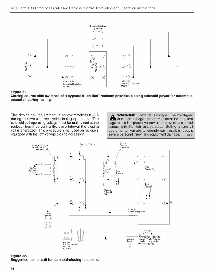
Kyle Form 4C Microprocessor-Based Recloser Control Installation and Operation Instructions
The closing coil requirement is approximately 200 kVAduring the two-to-three cycle closing operation. Thesolenoid coil operating voltage must be maintained at therecloser bushings during the cycle interval the closingcoil is energized. This procedure is not used on reclosersequipped with the low-voltage closing accessory.
3
6
4
T3Y
H
X
Z
Voltage Rating ofRecloser Closing
Solenoid Coil
Sensing CT's (3) ClosingSolenoidContactor
RotarySolenoid
MainContact(s)
G K
A B
E F
To240 or
480 VacSource
To240 VacSource
ClosingSolenoidCoil
TripSolenoid
ControlCable Receptacle
W
ElectronicControl
ToAmmeter and Relay tooperate Cycle Counteror other timing device
120 VacVariableAutotransformer240 Vac20 Amps
T2
1 2
5
J
Figure 32.Suggested test circuit for solenoid-closing reclosers.
WARNING: Hazardous voltage. The switchgearand high voltage transformer must be in a test
cage or similar protective device to prevent accidentalcontact with the high voltage parts. Solidly ground allequipment. Failure to comply can result in death,severe personal injury, and equipment damage. T221.3
!
5 6
3 4
1 2
C
B
A
Bypass Switches(Closed)
Source SideDisconnect Switches(Closed)
Load SideDisconnect Switches(Open)
ClosingC
oil
LOA
D
SO
UR
CES
OU
RC
E
LOA
D
Figure 31.Closing source-side switches of a bypassed “on-line” recloser provides closing solenoid power for automaticoperation during testing.
44

S280-77-1!
SAFETYFOR LIFE
Electrical Closing - Motor-OperatedReclosersHigh-voltage is not required for reclosers utilizing amotor-operated closing mechanism energized from a240 Vac power source. For information on energizingthe recloser, refer to the appropriate motor-operatedrecloser installation manual.
Figure 33 shows a test circuit for motor-operatedreclosers. Since these reclosers require only a 240 Vacsource for closing, high-voltage transformer T3 and itsprotective cage is eliminated. All other equipment is thesame as the test equipment shown in Figure 34.
Electrical Closing – NOVA™ ReclosersType NOVA 3-phase reclosers utilize an interface circuitlocated in the mechanism housing. The electronic inter-face circuit controls the opening and closing signals to themetal actuator.
The control-powered NOVA Recloser is tested with thedc-to-dc converter and 19-pin cable connected to the dcpower supply.
Figure 33.Suggested test circuit for motor-operated reclosers,solenoid closing reclosers with low voltage closing,and NOVA reclosers.
65
43
21
ElectronicControl
J
G K
H
X W
240 VacPowerSupply
ClosingMotor
T1 T2
240 Vac
VariableAutotransformer240 Vac-20 A
120 Vac
To Ammeterand Relayto operatecycle counter orother timingdevice
Sensing CT's (3)
WARNING: Hazardous voltage. Solidlyground all equipment. Failure to comply can
result in death, severe personal injury, and equipmentdamage. T223.2
!
Figure 34.Alternate method of producing variable linecurrent (substitute for T2 and W-X circuit inFigures 32 and 33).
115 Vac
1 2 Clamp-OnAmmeter
VariableAutotransformer (10 Amp)
600:5RecloserBCT ON 600:5 Tap
Note: Use at least 2/0 cable between bushings.
Note: This test circuit can apply over 800 Amps to the recloser.
45

Kyle Form 4C Microprocessor-Based Recloser Control Installation and Operation Instructions
Manual Closing - Solenoid-OperatedReclosersIf high-voltage for operating the closing solenoid is notavailable, manual closing can be substituted for electri-cal closing. However, not all control settings can bechecked since manual closing is not synchronized withthe closing coil control circuit in the control.
To manually close the recloser:
1. Remove the closing tool port cover and gasket fromthe side of the recloser head casting.
2. Insert the tee-handled tool (available as an accesso-ry) into the port, engaging the pin on the closingshaft (Figure 35).
3. Close the recloser by placing the yellow operatinghandle (located under the sleethood) into the up orCLOSED position and turning the closing tool one-quarter turn clockwise.
4. After each trip operation, about 1/2 second elapseswhile the closing solenoid plunger is moving upwardto reset the main toggle latch.
5. After the main toggle latch resets, the recloser canbe closed again by operating the manual closingtool.
6. Replace the gasket and port cover on the recloserhead after testing has been completed.
Return the Control to Service
After the required work is completed, disconnect thecontrol from the test set and follow this procedure toreturn the control to service:
1. While still in service shop, appropriate personnelmust verify that all control settings are correct.
2. Reconnect the ground cable to the control.
3. Control cable properly connected and supported.
4. Plug in the control battery.
Note: The Form 4C control will not power up until acpower is applied.
5. Apply ac power to the control.
6. Switch Ground Trip Block switch to NORMAL.
7. Reset the control clock after ac power has been re-applied. (Refer to the Setting The Control Clocksection of S280-77-4 Form 4C Control ProgrammingGuide.)
Figure 35.Using a manual closing tool to operate the recloser.
82284KMA-F
WARNING: Explosion Hazard. ExcessiveContact Arcing. Do not use the manual closing
tool to close an oil-insulated energized recloser. Clos-ing an energized oil-insulated recloser with a manualclosing tool can cause excessive contact arcing, rapidbuild-up of gas within the equipment, and possibleexplosion that can cause death, severe personal injury,and equipment damage. T203.2
!
CAUTION: Equipment damage. Do not turn themanual closing tool more than one-quarter turn clock-wise. Forcing the tool beyond the mechanism stopmay shear the pin on the closing shaft of the recloser.
T222.0
IMPORTANT: If manual closing is used during triptesting, the Form 4C control’s manual closing must besyncronized with the control‘s close signal.
If the recloser is not manually closed before the Form4C control completes its closing signal, the control willgo into its close-retry mode.
At this point, if the recloser is manually closed, thecontrol will define the recloser contact position as notvalid. The control will trip the recloser and lockout.
46
CAUTION: Equipment misoperation. Do notconnect this control to an energized recloser
until all control settings have been properly pro-grammed and verified. Refer to the programming infor-mation for this control. Failure to comply can result incontrol and recloser misoperation, equipment damage,and personal injury. G110.3
!

47
S280-77-1!
SAFETYFOR LIFE
MAINTENANCE INFORMATION
Replacement KitsReplacement kits for the Kyle Form 4C Control are avail-able through the factory Service Department. To orderthese kits, refer to the Replacement Parts price list forcatalog numbers and pricing. Contact your CooperPower Systems representative for additional informationand ordering procedures.
Factory-Authorized ServiceCentersFactory-authorized service centers are located through-out the continental United States to provide mainte-nance, repair and testing services for Kyle controls andreclosers. For further information, contact your CooperPower Systems representative.
Factory Maintenance ClassesThe factory service department offers a basic testing andtroubleshooting course for the Form 4C Microprocessor-based Control and Reclosers. This course, taught byexperienced service technicians, is held at the factory‘sin-house training facility. For additional information, con-tact your Cooper Power Systems sales representative.
Instructional Video CassetteProgramsForm 4C ControlA video cassette program entitled KSPV9 Form 4CMicroprocessor-Based Control Description and Opera-tion is available as a supplemental training aid for oper-ating and service personnel.
This video program, developed for use in the factorytraining school, is used in conjunction with existing ser-vice literature. For additional information, contact yourCooper Power Systems representative.
Type MET Recloser Control TesterA 30-minute video cassette program, KSPV7 Kyle® TypeMET Electronic Recloser Control Tester Operation andTesting Procedures is available as a supplemental train-ing aid for service personnel.
CAUTION: This equipment requires routineinspection and maintenance to ensure proper
operation. If it is not maintained, it can fail to operateproperly. Improper operation can cause equipmentdamage and possible personal injury. G105.1
!

48
Kyle Form 4C Microprocessor-Based Recloser Control Installation and Operation Instructions
The front panel assembly of the Form 4C recloser con-trol contains all the necessary software for programmingthe control parameters.
To remove the control front panel, refer to Figure 36 andproceed as follows:
1. Remove the control from service. Follow all local-ly approved safety regulations, practices, andprocedures.
A. Set Ground Trip Block switch to BLOCK.
B. Unplug the control battery.
C. Remove control ac sensing and power connectionsfrom the control using a separate disconnect switch.
D. Disconnect control cable from the control.
Note: If the control is connected to a control-poweredNOVA recloser, wait approximately 10 minutesfor the 53 Vdc to dissipate from the control cablebefore touching the pins in the male end.
2. Disconnect the front-panel ground strap by removingthe #8 nut and lockwasher. Retain these parts forlater use.
3. Disconnect the cable plug from socket P7 on theStandard Universal I/O board. Release the cablefrom the tie-wraps and wire clips.
4. Disconnect the cable plug from the power supplyplug P12. Release cable from tie-wraps and wireclips.
5. If control is equipped with the Optional Universal I/Oboard, disconnect cable plug from socket P15.Release the cable from its tie-wraps and wire clips.
6. If control is equipped with the Fiber-Optic DigitalCommunications accessory, disconnect cable plugfrom socket P19.
7. Disconnect the cable plug from socket P2 on the top-right corner, on the back of the front panel assembly.Remove and retain the cable clamp and hardwarefrom the cable.
8. Disconnect the front panel door-stop link. Retain forlater use.
9. Remove the panel by lifting it off the slide hinges.
REMOVAL OF CONTROL FRONT PANEL ASSEMBLY
CAUTION: Equipment damage. Always wear agrounding wrist strap to control static electricity beforehandling circuit boards. Failure to use this strap mayresult in circuit board damage. T253.1
CAUTION: Recloser misoperation. The controlmust be removed from service before discon-
necting the control battery. Disconnecting the controlbattery from an in-service control may cause reclosermisoperation (unintentional operation). Failure tocomply can result in equipment damage and personalinjury. T213.4
!
CAUTION: Control damage. De-energize both acand dc power prior to removing or installing any inter-nal connections or circuit boards in the control. Failureto comply can result in damage to the control. T241.1
IMPORTANT: Disconnect switches for ac sensingand power connections are necessary to isolate theForm 4C Recloser Control for testing and servicing.
WARNING: Hazardous voltage. If the recloseris energized while the control cable is discon-
nected, the CT secondaries can generate high volt-ages. Contact with high voltage can cause severepersonal injury or death. T204.2
!
CAUTION: Hazardous voltage. Cable conduc-tors attached to NOVA reclosers will remain at
53Vdc potential after disconnection of source powerto the recloser. Contact with any pins at the end ofcables directly or indirectly connected to a NOVArecloser can result in personal injury or equipmentdamage. T312.0
!
IMPORTANT: Electro-static discharge. All micro-processor equipment is subject to electrostatic dis-charge (ESD) damage which can affect programmingor result in component degradation or failure.
To prevent possible ESD damage to circuit boards,make sure of the following when removing, handling,or installing circuit boards.
• Make sure the control is grounded.
• Use a grounding wrist strap connected to the con-trol ground connection.
• Always transport and store circuit boards in static-free packaging.
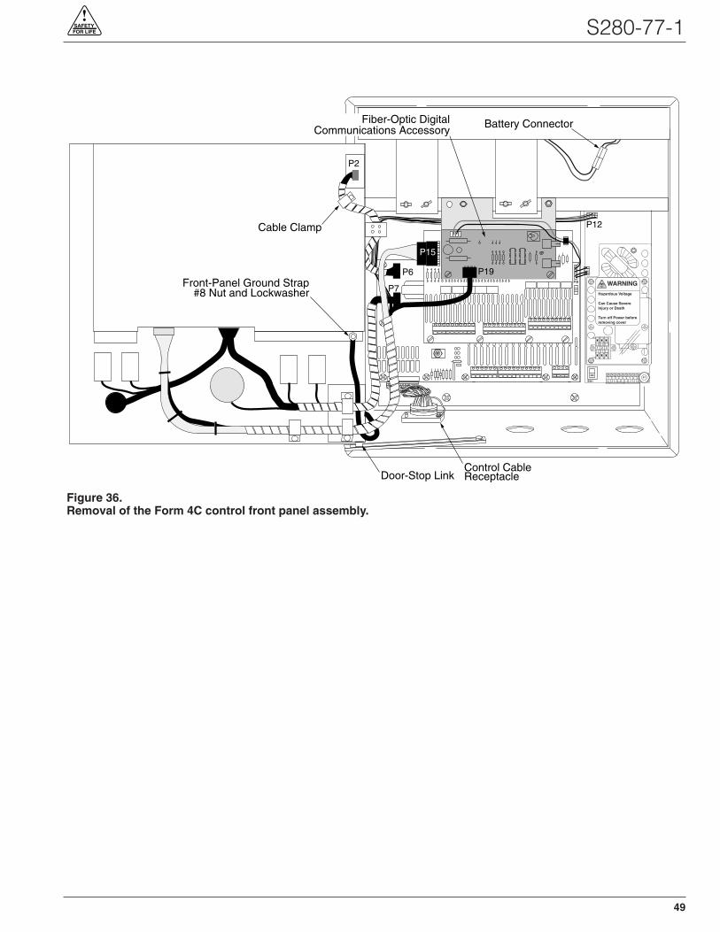
49
S280-77-1!
SAFETYFOR LIFE
Control CableReceptacle
P8
P19
P12
P6
P2
P7
Door-Stop Link
Battery Connector
P15
Front-Panel Ground Strap#8 Nut and Lockwasher
Cable Clamp
Fiber-Optic DigitalCommunications Accessory
1 2 3 4 5 6 7 8 9
WARNING
Hazardous Voltage
Can Cause SevereInjury or Death
Turn off Power beforeremoving cover
F1
1 2 3
SW1
Figure 36.Removal of the Form 4C control front panel assembly.
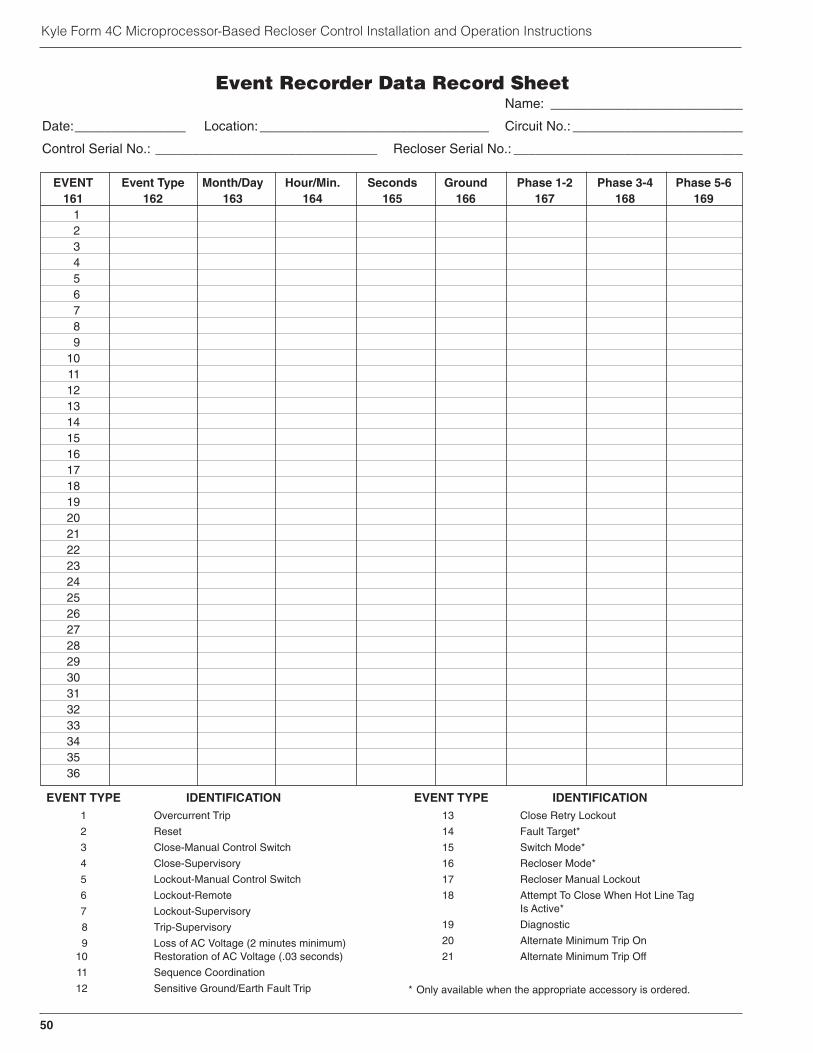
50
Kyle Form 4C Microprocessor-Based Recloser Control Installation and Operation Instructions
EVENT Event Type Month/Day Hour/Min. Seconds Ground Phase 1-2 Phase 3-4 Phase 5-6161 162 163 164 165 166 167 168 169
123456789
101112131415161718192021222324252627282930313233343536
EVENT TYPE IDENTIFICATION1 Overcurrent Trip
2 Reset
3 Close-Manual Control Switch
4 Close-Supervisory
5 Lockout-Manual Control Switch
6 Lockout-Remote
7 Lockout-Supervisory
8 Trip-Supervisory
9 Loss of AC Voltage (2 minutes minimum)10 Restoration of AC Voltage (.03 seconds)
11 Sequence Coordination
12 Sensitive Ground/Earth Fault Trip
EVENT TYPE IDENTIFICATION13 Close Retry Lockout
14 Fault Target*
15 Switch Mode*
16 Recloser Mode*
17 Recloser Manual Lockout
18 Attempt To Close When Hot Line TagIs Active*
19 Diagnostic
20 Alternate Minimum Trip On
21 Alternate Minimum Trip Off
* Only available when the appropriate accessory is ordered.
Event Recorder Data Record SheetName: __________________________
Date:_______________ Location:_______________________________ Circuit No.: _______________________
Control Serial No.: ______________________________ Recloser Serial No.: _______________________________

51
S280-77-1!
SAFETYFOR LIFE

KA2048-434 Rev: 02
Kyle Form 4C Microprocessor-Based Recloser Control Installation and Operation Instructions
KDL9/04
1045 Hickory StreetPewaukee, WI 53072www.cooperpower.com
©2004 Cooper Power Systems, Inc.Kyle® is a registered trademark of Cooper Power Systems or its affiliates.NOVATM is a trademark of Cooper Power Systems or its affiliates.
!SAFETYFOR LIFE