s1r72u06 technical manual - epson corporateglobal.epson.com/products_and_drivers/semicon/pdf/id...2....
TRANSCRIPT

Rev. 1.00
S1R72U06
Technical Manual

NOTICE
No part of this material may be reproduced or duplicated in any form or by any means without the written permission of Seiko Epson. Seiko Epson reserves the right to make changes to this material without notice. Seiko Epson does not assume any liability of any kind arising out of any inaccuracies contained in this material or due to its application or use in any product or circuit and, further, there is no representation that this material is applicable to products requiring high level reliability, such as, medical products. Moreover, no license to any intellectual property rights is granted by implication or otherwise, and there is no representation or warranty that anything made in accordance with this material will be free from any patent or copyright infringement of a third party. This material or portions thereof may contain technology or the subject relating to strategic products under the control of the Foreign Exchange and Foreign Trade Law of Japan and may require an export license from the Ministry of Economy, Trade and Industry or other approval from another government agency.
All other product names mentioned herein are trademarks and/or registered trademarks of their respective companies.
©SEIKO EPSON CORPORATION 2009, All rights reserved.

Scope
This document applies to the S1R72U06 serial (UART/SPI) – USB Host/Device bridge LSI, which supports USB
2.0 FS/LS.

S1R72U06 Technical Manual EPSON i (Rev. 1.00)
Table of Contents
1. Overview ....................................................................................................................... 1
2. Compliance................................................................................................................... 2
3. Terminology .................................................................................................................. 3
4. System Configuration .................................................................................................. 4
4.1 UART – USB Host configuration ............................................................................................. 4
4.2 UART – USB Device configuration.......................................................................................... 4
4.3 SPI – USB Host configuration ................................................................................................. 5
4.4 SPI – USB Device configuration.............................................................................................. 5
5. Functions ...................................................................................................................... 6
6. UART Function ............................................................................................................. 7
6.1 UART Overview......................................................................................................................... 7
6.2 UART settings........................................................................................................................... 8 6.2.1 Initial settings ...................................................................................................................... 8 6.2.2 Communication settings...................................................................................................... 8
6.3 UART event control .................................................................................................................. 9
6.4 UART Status information ....................................................................................................... 10 6.4.1 Buffer Overflow Error ........................................................................................................ 10 6.4.2 Parity Error........................................................................................................................ 10 6.4.3 Framing Error.................................................................................................................... 10 6.4.4 Noise Detection................................................................................................................. 10 6.4.5 Protocol Error.................................................................................................................... 10 6.4.6 Condition........................................................................................................................... 11
6.5 Precautions ............................................................................................................................. 11
7. SPI Function ............................................................................................................... 12
7.1 SPI Overview........................................................................................................................... 12
7.2 SPI settings............................................................................................................................. 13 7.2.1 Initial settings .................................................................................................................... 13 7.2.2 Communication settings.................................................................................................... 13
7.3 SPI event control .................................................................................................................... 13
7.4 SPI Status information ........................................................................................................... 14 7.4.1 Protocol Error.................................................................................................................... 14 7.4.2 Burst RcvShort .................................................................................................................. 14 7.4.3 Condition........................................................................................................................... 14
7.5 SPI short data size information ............................................................................................. 15
7.6 Precautions ............................................................................................................................. 15
8. USB Host Function..................................................................................................... 16
8.1 Host Overview......................................................................................................................... 16 8.1.1 HID Class Host Overview.................................................................................................. 16 8.1.2 MSC Host Overview.......................................................................................................... 16
8.1.2.1 Simple control............................................................................................................... 16

ii EPSON S1R72U06 Technical Manual (Rev. 1.00)
8.1.2.2 Full control.................................................................................................................... 16
8.2 Host initial settings ................................................................................................................ 16
8.3 Host operation setting............................................................................................................ 17 8.3.1 HID Class.......................................................................................................................... 17 8.3.2 MSC.................................................................................................................................. 17
8.4 Host event information........................................................................................................... 18 8.4.1 HID Class.......................................................................................................................... 18
8.4.1.1 Remote Wakeup........................................................................................................... 18
8.4.1.2 Rcv Input Report .......................................................................................................... 18
8.4.1.3 CD Change................................................................................................................... 18
8.4.1.4 CD ................................................................................................................................ 18 8.4.2 MSC.................................................................................................................................. 19
8.4.2.1 Command Through Ended ........................................................................................... 19
8.4.2.2 Remote Wakeup........................................................................................................... 19
8.4.2.3 CD Change................................................................................................................... 19
8.4.2.4 CD ................................................................................................................................ 19 8.4.3 Event Clear ....................................................................................................................... 20
8.4.3.1 UART clear conditions.................................................................................................. 20
8.4.3.2 SPI clear conditions...................................................................................................... 20
8.5 Host error information............................................................................................................ 21 8.5.1 HID Class.......................................................................................................................... 21
8.5.1.1 EI Req Aborted ............................................................................................................. 21
8.5.1.2 Invalid Parameter ......................................................................................................... 21
8.5.1.3 Req Unsupported ......................................................................................................... 21 8.5.2 MSC.................................................................................................................................. 22
8.5.2.1 Media Not Found.......................................................................................................... 22
8.5.2.2 Media Changed............................................................................................................ 22
8.5.2.3 Block Tran Ended ......................................................................................................... 22
8.5.2.4 Block Tran Executing.................................................................................................... 22
8.5.2.5 Device Error ................................................................................................................. 22
8.5.2.6 EI Req Aborted ............................................................................................................. 23
8.5.2.7 Invalid Parameter ......................................................................................................... 23
8.5.2.8 Req Unsupported ......................................................................................................... 23
8.6 VBUS control .......................................................................................................................... 23
8.7 NSF .......................................................................................................................................... 23
8.8 TPL........................................................................................................................................... 23 8.8.1 HID Class TPL .................................................................................................................. 23 8.8.2 MSC TPL .......................................................................................................................... 23
8.9 Precautions ............................................................................................................................. 24 8.9.1 For all Classes .................................................................................................................. 24 8.9.2 HID Class.......................................................................................................................... 24 8.9.3 MSC.................................................................................................................................. 24
9. USB Device Function ................................................................................................. 25
9.1 Device Overview ..................................................................................................................... 25
S1R72U06 Technical Manual EPSON iii (Rev. 1.00)
9.2 Device initial settings............................................................................................................. 25
9.3 Device operation setting........................................................................................................ 26 9.3.1 Descriptor Header ............................................................................................................. 27 9.3.2 Device Descriptor.............................................................................................................. 28 9.3.3 Configuration Descriptor ................................................................................................... 29 9.3.4 Interface Descriptor........................................................................................................... 30 9.3.5 HID Descriptor .................................................................................................................. 31 9.3.6 Endpoint Descriptor........................................................................................................... 32 9.3.7 String Language ID Descriptor .......................................................................................... 33 9.3.8 String Descriptor ............................................................................................................... 33 9.3.9 Report Descriptor .............................................................................................................. 34 9.3.10 Report ID Registration Information.................................................................................... 35
9.4 Device event information....................................................................................................... 36 9.4.1 USB Com Status ............................................................................................................... 36 9.4.2 USB Suspend Status......................................................................................................... 36 9.4.3 Detect Reset ..................................................................................................................... 36 9.4.4 Protocol Mode Change ..................................................................................................... 36 9.4.5 Rcv Feature Report........................................................................................................... 37 9.4.6 Rcv Output Report ............................................................................................................ 37 9.4.7 CD Change ....................................................................................................................... 37 9.4.8 CD..................................................................................................................................... 37 9.4.9 Event Clear ....................................................................................................................... 37
9.4.9.1 UART clear conditions.................................................................................................. 37
9.4.9.2 SPI clear conditions...................................................................................................... 37
9.5 Device error information........................................................................................................ 38 9.5.1 HID Start Failed................................................................................................................. 38 9.5.2 HID Req Failed ................................................................................................................. 38 9.5.3 EI Req Aborted.................................................................................................................. 38 9.5.4 Invalid Parameter .............................................................................................................. 38 9.5.5 Req Unsupported.............................................................................................................. 38
9.6 Precautions ............................................................................................................................. 39
10. Setting Function ....................................................................................................... 40
10.1 SPIxUART................................................................................................................................ 40
10.2 HOSTxDEVICE ........................................................................................................................ 40
10.3 WAKEUP.................................................................................................................................. 40
10.4 INIT_BAUD .............................................................................................................................. 40
11. Notification Function................................................................................................ 41
11.1 SIO_READY............................................................................................................................. 41
11.2 XIRQ_STATUS......................................................................................................................... 41 11.2.1 UART ................................................................................................................................ 41 11.2.2 SPI .................................................................................................................................... 41
11.3 XIRQ_EVENT........................................................................................................................... 42 11.3.1 PROTOCOL EVENT ......................................................................................................... 42
11.3.1.1 UART............................................................................................................................ 42
11.3.1.2 SPI ............................................................................................................................... 42 11.3.2 SLEEP EVENT.................................................................................................................. 42
11.4 TPL........................................................................................................................................... 42
11.5 ManyDev.................................................................................................................................. 42
iv EPSON S1R72U06 Technical Manual (Rev. 1.00)
11.6 ManyHub ................................................................................................................................. 43
11.7 VBUS_Cur ............................................................................................................................... 43
12. Development Support Functions ............................................................................ 44
13. HID Class Overview.................................................................................................. 45
13.1 HID Class transfer system ..................................................................................................... 45
13.2 HID Class time-related regulations ....................................................................................... 45
13.3 HID Class Report ID................................................................................................................ 46 13.3.1 Data using Report ID......................................................................................................... 46 13.3.2 Data not using Report ID................................................................................................... 46
13.4 HID Class protocols ............................................................................................................... 47 13.4.1 Boot Protocol .................................................................................................................... 47 13.4.2 Protocol comparison ......................................................................................................... 48
13.4.2.1 HID Class Host............................................................................................................. 48
13.4.2.2 HID Class Device ......................................................................................................... 48
13.5 Other........................................................................................................................................ 48
14. MSC Overview .......................................................................................................... 49
14.1 MSC transfer system.............................................................................................................. 49
14.2 MSC block transfer................................................................................................................. 49
14.3 Other........................................................................................................................................ 50
Appendix A Descriptor Setting Examples ................................................................. 51
A.1 Descriptor Header .................................................................................................................. 51
A.2 Device Descriptor ................................................................................................................... 51
A.3 Configuration Descriptor ....................................................................................................... 52
A.4 Interface Descriptor................................................................................................................ 52
A.5 HID Descriptor ........................................................................................................................ 53
A.6 Endpoint Descriptor ............................................................................................................... 53
A.7 String Language ID Descriptor.............................................................................................. 53
A.8 String Descriptor .................................................................................................................... 54
A.9 Report Descriptor ................................................................................................................... 55
A.10 Report ID Registration Information....................................................................................... 56
Appendix B UNICODE ................................................................................................. 57
Appendix C Country Code .......................................................................................... 58
Appendix D Report Descriptor Setting Examples..................................................... 59
D.1 Mouse setting examples ........................................................................................................ 59
D.2 Keyboard setting examples ................................................................................................... 60
D.3 Vendor -defined setting examples ........................................................................................ 61
D.4 Report Descriptor notes......................................................................................................... 62 D.4.1 Report ............................................................................................................................... 62 D.4.2 Item Tag ............................................................................................................................ 62
Appendix E Report ID Registration Information Setting Examples......................... 63

S1R72U06 Technical Manual EPSON v (Rev. 1.00)
E.1 Mouse setting examples ........................................................................................................ 63
E.2 Keyboard setting examples ................................................................................................... 63
E.3 Vendor-defined setting examples ......................................................................................... 64
Revision History ............................................................................................................. 65

1. Overview
S1R72U06 Technical Manual EPSON 1 (Rev. 1.00)
1. Overview
This is the Technical Manual for the S1R72U06 serial (UART/SPI) – USB Host/Device bridge LSI (hereinafter referred to as the “LSI”), which supports USB 2.0 FS/LS. This document supplements the hardware information for the LSI and provides the technical details needed to build the product using the S1R72U06 (hereafter referred to as the “system”).
The LSI provides the following related documents.
S1R72U06 Data Sheet ............................................Provides hardware information.
S1R72U06 Application Note..................................Provides the procedures for controlling and operating the LSI.
S1R72U06 UART Interface Manual ......................Provides UART command details.
S1R72U06 SPI Interface Manual ...........................Provides SPI command details.
S1R72U06 Development Support Manual .............Provides information to support system development.
2. Compliance
2 EPSON S1R72U06 Technical Manual (Rev. 1.00)
2. Compliance
The LSI complies with the following USB standards.
Universal Serial Bus Specification Revision 2.0
Speed mode: Supports FS and LS. (HS not supported)
Universal Serial Bus (USB) Device Class Definition for Human Interface Devices (HID) Version 1.11
Universal Serial Bus Mass Storage Class Bulk-Only Transport Revision 1.0
Multi-Media Commands - 5 (MMC - 5) [Supports CD/DVD]
INF - 8070i, INF - 8090i [Supports MO]
SFF - 8020i, SFF - 8080 [Supports CD]
QIC 157 Revision D [Supports tape devices]
SCSI Primary Commands - 3 (SPC-3)
SCSI Block Commands - 3 (SBC-3)
Reduced Block Commands Revision 10a (RBC)
Universal Serial Bus (USB) Language Identifiers (LANGIDs) Version 1.0

3. Terminology
S1R72U06 Technical Manual EPSON 3 (Rev. 1.00)
3. Terminology
SIO........................................... General term for the serial communications user interface.
UART....................................... Asynchronous serial communications.
SPI............................................ Synchronous serial communications.
USB.......................................... General term for products whose operations comply with the USB standard.
USB Host ................................. Product with a Host function that complies with the USB standard.
USB Device ............................. Product with a Device function that complies with the USB standard.
Class......................................... Definition related to control methods specified under the USB standard.
HID .......................................... Human interface device specified under the USB standard.
HID Class................................. Class defined by the USB standard specifically for human interface devices.
Mass Storage............................ Mass storage device specified under the USB standard.
Mass Storage Class (MSC) ...... Class defined by the USB standard specifically for mass storage.
Storage ..................................... Storage device for storing data.
Media ....................................... Storage media used for storage.
SCSI/ATAPI command............ Command for controlling storage Devices. For more information, refer to the standards referenced in “2. Compliance”.
HUB ......................................... HUB device specified under the USB standard.
LUN ......................................... Number assigned to the logical Device (logical area) logically divided within the storage Device.
Enumeration............................. Recognition process between USB Host and Device.
BUS reset ................................. USB BUS reset complying with the USB standard.
Soft reset .................................. Reset command issued via SIO.
Hardware reset ......................... Reset using the XRESET pin on the LSI.
Main CPU ................................ LSI controlling this LSI mounted in the system.
Write ........................................ Transfer from the Main CPU to this LSI.
Read ......................................... Transfer from this LSI to the Main CPU.
Transmit ................................... Transfer from this LSI to the USB.
Receive..................................... Transfer from the USB to this LSI.
EI request ................................. Command for controlling this LSI using SIO. (EPSON Interface)
Burst......................................... Data unit written or read at one time by SPI.
Block transfer........................... MSC data transmission/reception using USB Bulk transfer.
Payload..................................... Actual data involved in writing or reading data by MSC.
Complete .................................. Main CPU or USB processing has ended.
End ........................................... This LSI has ended internal processing. Also includes “end” as defined in standards.
4. System Configuration
4 EPSON S1R72U06 Technical Manual (Rev. 1.00)
4. System Configuration
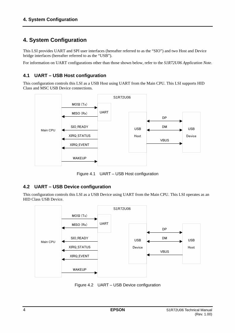
This LSI provides UART and SPI user interfaces (hereafter referred to as the “SIO”) and two Host and Device bridge interfaces (hereafter referred to as the “USB”).
For information on UART configurations other than those shown below, refer to the S1R72U06 Application Note.
4.1 UART – USB Host configuration
This configuration controls this LSI as a USB Host using UART from the Main CPU. This LSI supports HID Class and MSC USB Device connections.
Figure 4.1 UART – USB Host configuration
4.2 UART – USB Device configuration
This configuration controls this LSI as a USB Device using UART from the Main CPU. This LSI operates as an HID Class USB Device.
Figure 4.2 UART – USB Device configuration
MISO (Rx)
MOSI (Tx)
MainCPU
S1R72U06
SIO_READY
XIRQ_STATUS
XIRQ_EVENT
WAKEUP
USB
Device
DP
DM
VBUS
USB
Host
UART
MISO (Rx)
MOSI (Tx)
MainCPU
S1R72U06
SIO_READY
XIRQ_STATUS
XIRQ_EVENT
WAKEUP
USB
Device
DP
DM
VBUS
USB
Host
UART
Main CPU
Main CPU

4. System Configuration
S1R72U06 Technical Manual EPSON 5 (Rev. 1.00)
4.3 SPI – USB Host configuration
This configuration controls this LSI as a USB Host using SPI from the Main CPU. This LSI supports HID Class and MSC USB Device connections.
Figure 4.3 SPI – USB Host configuration
4.4 SPI – USB Device configuration
This configuration controls this LSI as a USB Device using SPI from the Main CPU. This LSI operates as an HID Class USB Device.
Figure 4.4 SPI – USB Device configuration
MISO (Rx)
MOSI (Tx)
MainCPU
S1R72U06
SS
SCK
SIO_READY
XIRQ_STATUS
XIRQ_EVENT
WAKEUP
USB
Device
DP
DM
VBUS
USB
Host
SPI
MISO (Rx)
MOSI (Tx)
MainCPU
S1R72U06
SS
SCK
SIO_READY
XIRQ_STATUS
XIRQ_EVENT
WAKEUP
USB
Device
DP
DM
VBUS
USB
Host
SPI
Main CPU
Main CPU

5. Functions
6 EPSON S1R72U06 Technical Manual (Rev. 1.00)
5. Functions
This LSI enables USB (Host/Device) control using SIO (UART/SPI). USB-compliant operations are controlled by the LSI.
The LSI includes functions for setting LSI operations and for notifying the Main CPU of LSI status.
The LSI also includes functions that support system development.
Items in this document such as “HID START” (10h) refer to the EI request “HID START” and the EI request code (10h). For more information on EI requests, refer to the S1R72U06 UART Interface Manual or S1R72U06 SPI Interface Manual.
Table 5.1 lists the functions provided by this LSI. The USB Device function does not include MSC. Details of each function are given in the subsequent pages of this document.
Table 5.1 Function list
SIO USB
UART SPI
HID Class Host
MSC
HID Class Device
MSC
6. UART Function
S1R72U06 Technical Manual EPSON 7 (Rev. 1.00)
6. UART Function
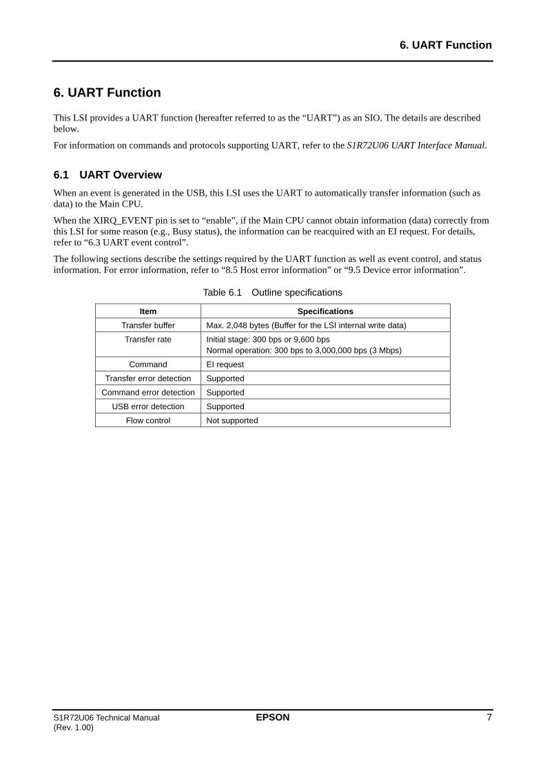
This LSI provides a UART function (hereafter referred to as the “UART”) as an SIO. The details are described below.
For information on commands and protocols supporting UART, refer to the S1R72U06 UART Interface Manual.
6.1 UART Overview
When an event is generated in the USB, this LSI uses the UART to automatically transfer information (such as data) to the Main CPU.
When the XIRQ_EVENT pin is set to “enable”, if the Main CPU cannot obtain information (data) correctly from this LSI for some reason (e.g., Busy status), the information can be reacquired with an EI request. For details, refer to “6.3 UART event control”.
The following sections describe the settings required by the UART function as well as event control, and status information. For error information, refer to “8.5 Host error information” or “9.5 Device error information”.
Table 6.1 Outline specifications
Item Specifications
Transfer buffer Max. 2,048 bytes (Buffer for the LSI internal write data)
Transfer rate Initial stage: 300 bps or 9,600 bps Normal operation: 300 bps to 3,000,000 bps (3 Mbps)
Command EI request
Transfer error detection Supported
Command error detection Supported
USB error detection Supported
Flow control Not supported

6. UART Function
8 EPSON S1R72U06 Technical Manual (Rev. 1.00)
6.2 UART settings
6.2.1 Initial settings
Set the pins shown in Table 6.2 to the initial settings using this LSI’s setting function. For details, refer to “10. Setting Function”.
Table 6.2 Initial settings
Setting item Pin Setting
UART selection SPIxUART Low
Initial baud rate INIT_BAUD Low (300 bps) or High (9,600 bps)
SCK Low Other
SS *
* The setting for this pin can control the MISO pin status. For more information, refer to the S1R72U06 Data Sheet.
6.2.2 Communication settings
Set the UART communication conditions using an EI request. Note that this LSI does not support flow control. Table 6.3 shows the default values. For details, refer to “SERIAL PORT” (F8h) in the S1R72U06 UART Interface Manual.
Table 6.3 Communication settings
Item Default value
Data bit 8 (fixed)
Stop bit 1
Parity None
Flow control None (fixed)

6. UART Function
S1R72U06 Technical Manual EPSON 9 (Rev. 1.00)
6.3 UART event control
Event information is obtained in two ways with UART: directly or via reacquisition following notification by the XIRQ_EVENT pin. How event information is controlled depends on settings. For detailed information on pin settings, refer to “EVENT INT CONTROL” (FFh) in the S1R72U06 UART Interface Manual.
The XIRQ_EVENT pin is set to “disable” in the UART default condition. This means that event information is acquired directly. Refer to Figure 6.1.
When the pin is set to “enable”, event information is transferred concurrently with notification from the XIRQ_EVENT pin. However, since control assumes reacquisition, event information must be reacquired. Refer to Figure 6.2.
For detailed event information, refer to “8.4 Host event information” and “9.4 Device event information”.
Figure 6.1 XIRQ_EVENT pin set to disable (default)
Figure 6.2 XIRQ_EVENT pin set to enable
MOSI (Tx) pin
MISO (Rx) pin
EI request
Event information reacquisition
Event informationEI header Event information is
cleared after transfer.
Event information is retained until GET_EVENT is written.
XIRQ_EVENT pin
MISO (Rx) pin
Event generation
Changes to “Low” during event information transfer.
MOSI (Tx) pin
Event informationEI header
Event information is cleared after transfer.
MISO (Rx) pin Event informationEI header
Event generation
Event information is cleared after transfer.
MOSI (Tx) pin

6. UART Function
10 EPSON S1R72U06 Technical Manual (Rev. 1.00)
6.4 UART Status information
Table 6.4 lists UART status information. The status of Bits 7 to 4 is communicated to the Main CPU on detection. For details, refer to “Notification transfer” in the S1R72U06 UART Interface Manual. Note that information on Bits 3 and 1 to 0 is not sent to the Main CPU if they change and must be obtained using “GET STATUS” (F2h). The error status persists until the next EI request is written.
The status information is the same for both the USB Host and Device.
Table 6.4 Status information
Bit Content Description
7 Buffer Overflow Error 0b: Normal 1b: Error
6 Parity Error 0b: Normal 1b: Error
5 Framing Error 0b: Normal 1b: Error
4 Noise Detection 0b: Normal 1b: Noise Detection
3 Protocol Error 0b: Normal 1b: Error
2 reserved
1-0 Condition 00b: Idle 01b: Busy 10b, 11b: reserved
6.4.1 Buffer Overflow Error
This is generated when an overflow occurs in the UART reception buffer of this LSI. Refer to “12. Development Support Functions”.
6.4.2 Parity Error
This indicates the detection of a parity error during the reception of UART data by this LSI. Refer to “12. Development Support Functions”.
6.4.3 Framing Error
This indicates the detection of a framing error during the reception of UART data by this LSI. Refer to “12. Development Support Functions”.
6.4.4 Noise Detection
This indicates the detection of noise during the reception of UART data by this LSI. This LSI performs multiple sampling operations for one data set; if a mismatch results in sampling results, it is determined to be noise. Refer to “12. Development Support Functions”.
6.4.5 Protocol Error
This indicates a protocol error. For more information on errors, refer to “8.5 Host error information” or “9.5 Device error information”.

6. UART Function
S1R72U06 Technical Manual EPSON 11 (Rev. 1.00)
6.4.6 Condition
This indicates the internal state of the LSI. A change in internal state causes the XIRQ_STATUS pin status to change. For more information, refer to “11.2.1 UART”.
(1) Idle Indicates a standby state.
(2) Busy Indicates a command is being processed.
6.5 Precautions
(1) Care must be taken regarding transfer speed and other factors to prevent overflow from occurring in the Main CPU during data transfer from the LSI.
(2) The LSI does not support reacquisition of transfer data, so design must ensure that data is acquired reliably (using circuit board wiring lengths, measures to prevent noise interference in patterns, etc.).
(3) The LSI is designed for one-to-one connection to the Main CPU, and so does not support multistage connections.
(4) When using MSC Host, using the highest practical transfer speed is recommended.

7. SPI Function
12 EPSON S1R72U06 Technical Manual (Rev. 1.00)
7. SPI Function
This LSI provides an SPI function (hereafter referred to as the “SPI”) as an SIO. Details are described below.
For detailed information on commands and protocols supporting SPI, refer to the S1R72U06 SPI Interface Manual.
7.1 SPI Overview
SPI with this LSI uses “positive pulse, latch first” Mode 0.
The LSI uses the notification function to notify the Main CPU of changes in the USB state. The Main CPU should check the information (data) using SPI. For detailed information on the notification function, refer to “11. Notification Function”.
SPI transfers data in Burst units. For detailed information on Burst size, refer to “7.2.2 Communication settings”.
The following sections discuss settings, event control, status information, and short data size information required by the SPI function. For error information, refer to “8.5 Host error information” or “9.5 Device error information”.
Table 7.1 Outline specifications
Item Specifications
Transfer buffer Max. 2,048 bytes (Buffer for the LSI internal write data)
Transfer frequency Max. 6 MHz
Command Register, EI request
Transfer error detection Not supported
Command error detection Supported
USB error detection Supported
Soft reset Can also be used with HID Class
7. SPI Function
S1R72U06 Technical Manual EPSON 13 (Rev. 1.00)
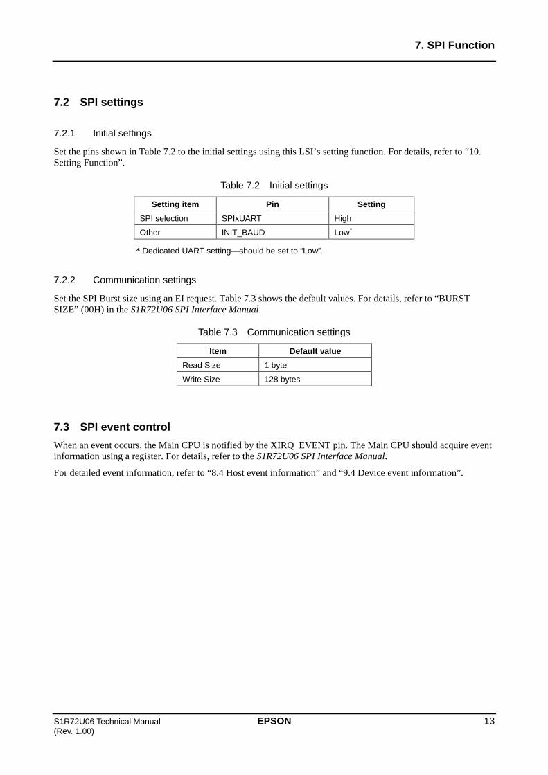
7.2 SPI settings
7.2.1 Initial settings
Set the pins shown in Table 7.2 to the initial settings using this LSI’s setting function. For details, refer to “10. Setting Function”.
Table 7.2 Initial settings
Setting item Pin Setting
SPI selection SPIxUART High
Other INIT_BAUD Low*
* Dedicated UART settingshould be set to “Low”.
7.2.2 Communication settings
Set the SPI Burst size using an EI request. Table 7.3 shows the default values. For details, refer to “BURST SIZE” (00H) in the S1R72U06 SPI Interface Manual.
Table 7.3 Communication settings
Item Default value
Read Size 1 byte
Write Size 128 bytes
7.3 SPI event control
When an event occurs, the Main CPU is notified by the XIRQ_EVENT pin. The Main CPU should acquire event information using a register. For details, refer to the S1R72U06 SPI Interface Manual.
For detailed event information, refer to “8.4 Host event information” and “9.4 Device event information”.

7. SPI Function
14 EPSON S1R72U06 Technical Manual (Rev. 1.00)
7.4 SPI Status information
Table 7.4 lists the SPI status information.
The status information is the same for both the USB Host and Device.
Table 7.4 Status information
Bit Content Description
7-4 reserved
3 Protocol Error 0b: Normal 1b: Error
2 Burst RcvShort 0b: Normal Data 1b: Short Data
1-0 Condition 00b: Idle 01b: Busy 10b: reserved 11b: TranRdy
7.4.1 Protocol Error
This indicates that a protocol error has occurred. It is communicated to the Main CPU by the XIRQ_STATUS pin together with the internal status change in “7.4.3 Condition”. It is retained until the next EI request or “SRST” (47h) is written. For more information on errors, refer to “8.5 Host error information” or “9.5 Device error information”.
7.4.2 Burst RcvShort
This state is enabled when the Main CPU reads data from the LSI. It indicates that data exists less than the Burst size. For more information, refer to “7.5 SPI short data size information”.
7.4.3 Condition
This indicates the internal state of the LSI. A change in internal state causes the XIRQ_STATUS pin status to change. For more information, refer to “11.2.2 SPI”.
(1) Idle Indicates a standby state.
(2) Busy Indicates a command is being processed.
(3) TranRdy Indicates data can be transferred.
7. SPI Function
S1R72U06 Technical Manual EPSON 15 (Rev. 1.00)
7.5 SPI short data size information
Data read from the LSI by the Main CPU is read in Burst size units. However, if the last data unit is smaller than the Burst size, this information must be checked to confirm the valid data size. For detailed information, refer to “ReceiveDataSize” (86h) in the S1R72U06 SPI Interface Manual.
7.6 Precautions
(1) Care must be taken regarding transfer speed and other factors to prevent overflow from occurring in the Main CPU during data transfer from the LSI.
(2) The LSI does not support reacquisition of transfer data, so design must ensure that data is acquired reliably (using circuit board wiring lengths, measures to prevent noise interference in patterns, etc.).
(3) When using MSC Host, using the highest practical transfer speed is recommended.

8. USB Host Function
16 EPSON S1R72U06 Technical Manual (Rev. 1.00)
8. USB Host Function
This LSI incorporates a USB Host function. This function is described in detail below.
8.1 Host Overview
The Host function of this LSI supports HID Class and MSC LS and FS (HS is not supported).
One USB Device at a time can be connected to this LSI.
This LSI handles control processing for USB Devices that comply with the USB standard. By performing initial setting and event processing, the Main CPU can easily provide control processing for USB Devices.
The following sections describe the settings required by the USB Host function as well as event information, error information, VBUS control, NSF, and TPL.
8.1.1 HID Class Host Overview
The LSI supports Devices that comply with the USB HID Class. Refer to “13. HID Class Overview”.
8.1.2 MSC Host Overview
The LSI supports Devices that comply with the USB MSC. Refer to “14. MSC Overview”.
The LSI can recognize only one LUN (LUN0).
The LSI includes the control methods described below. For details, refer to the S1R72U06 Application Note.
8.1.2.1 Simple control
This control method enables USB MSC Devices to be controlled easily without the need for detailed knowledge of SCSI/ATAPI standards.
8.1.2.2 Full control
This control method allows command control in compliance with the SCSI/ATAPI standards. For details of the standards, refer to “2. Compliance”.
Please note that Seiko Epson cannot respond to inquiries related to SCSI/ATAPI. Users not familiar with SCSI/ATAPI are recommended to use “8.1.2.1 Simple control”.
8.2 Host initial settings
Set the pin shown in Table 8.1 to the initial setting using this LSI’s setting function. For detailed information, refer to “10. Setting Function”.
Table 8.1 Initial setting
Setting item Pin Setting
HOST selection HOSTxDEVICE High

8. USB Host Function
S1R72U06 Technical Manual EPSON 17 (Rev. 1.00)
8.3 Host operation setting
For details of the initialization flow, refer to the S1R72U06 Application Note.
8.3.1 HID Class
When using Report Protocol, the Main CPU should acquire the Report Descriptor from the Device connected. Report ID registration information must be set in the LSI using “REPORT ID REGISTRATION” (11h). For detailed information on setting examples, refer to Appendix E “Report ID Registration Information Setting Examples”. No setting is required when using Boot Protocol.
Figure 8.1 illustrates HID Class descriptors. Physical Descriptors are not supported.
For detailed information on descriptors, refer to “9.3 Device operation setting”.
Figure 8.1 HID Class descriptors
8.3.2 MSC
There are no descriptor-related settings.
The Main CPU should acquire storage information from the Device connected. For more information on connection and disconnection, refer to the S1R72U06 Application Note.
Common descriptors
Device Descriptor
Configuration Descriptor
Interface Descriptor
Endpoint Descriptor
String Descriptor
HID Descriptor
Report Descriptor
HID Descriptors

8. USB Host Function
18 EPSON S1R72U06 Technical Manual (Rev. 1.00)
8.4 Host event information
The Main CPU is notified if an event occurs while the Host is running. For more information, refer to “6.3 UART event control” and “7.3 SPI event control”.
8.4.1 HID Class
Table 8.2 lists HID Class event information.
Table 8.2 HID Class event information
Bit Content Description
7-4 reserved
3 Remote Wakeup 0b: Normal 1b: Detect (Event)
2 Rcv Input Report 0b: Normal 1b: Receive (Event)
1 CD Change 0b: Normal 1b: Change (Event)
0 CD (Connection Detect)
0b: Disconnect 1b: Connect
8.4.1.1 Remote Wakeup
This event is generated when a Remote Wakeup occurs in the Device.
8.4.1.2 Rcv Input Report
When the XIRQ_EVENT pin is set to “enable”, an event occurs if data is received via Input Report transfer from a Device. Note that this event does not occur if the XIRQ_EVENT pin is set to “disable”, since data is transferred to the Main CPU when data reception from the Device is complete.
8.4.1.3 CD Change
This event is generated when a change occurs in CD. (Refer to 8.4.1.4)
8.4.1.4 CD
The status changes when a Device is connected to or disconnected from the LSI and USB processing is completed. For more information on connection and disconnection, refer to the S1R72U06 Application Note.
8. USB Host Function
S1R72U06 Technical Manual EPSON 19 (Rev. 1.00)
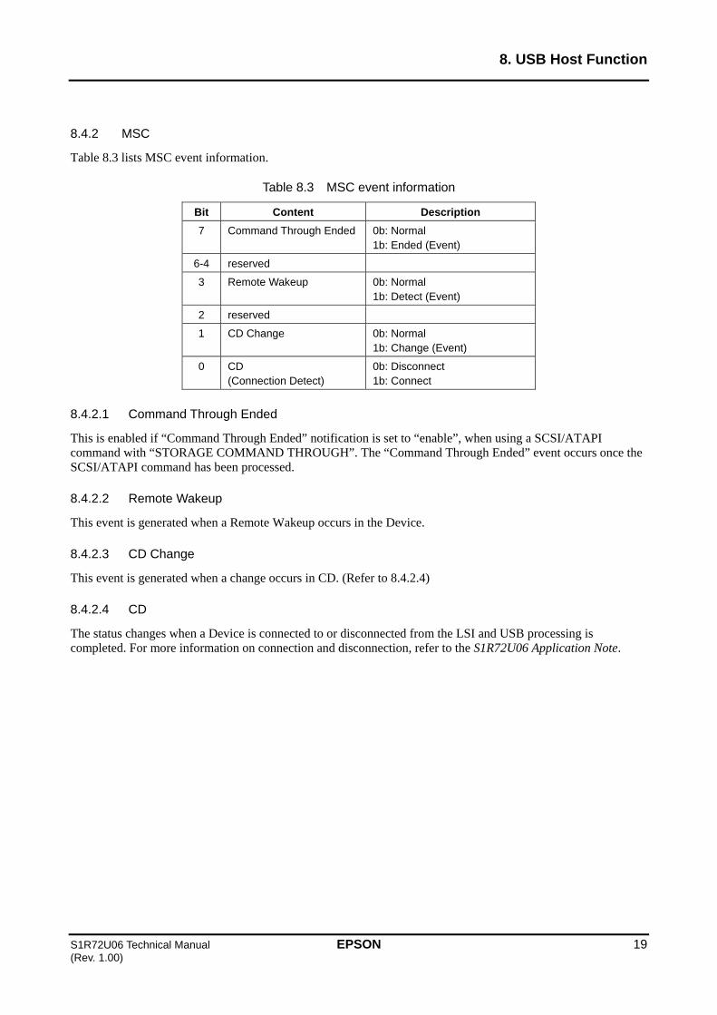
8.4.2 MSC
Table 8.3 lists MSC event information.
Table 8.3 MSC event information
Bit Content Description
7 Command Through Ended 0b: Normal 1b: Ended (Event)
6-4 reserved
3 Remote Wakeup 0b: Normal 1b: Detect (Event)
2 reserved
1 CD Change 0b: Normal 1b: Change (Event)
0 CD (Connection Detect)
0b: Disconnect 1b: Connect
8.4.2.1 Command Through Ended
This is enabled if “Command Through Ended” notification is set to “enable”, when using a SCSI/ATAPI command with “STORAGE COMMAND THROUGH”. The “Command Through Ended” event occurs once the SCSI/ATAPI command has been processed.
8.4.2.2 Remote Wakeup
This event is generated when a Remote Wakeup occurs in the Device.
8.4.2.3 CD Change
This event is generated when a change occurs in CD. (Refer to 8.4.2.4)
8.4.2.4 CD
The status changes when a Device is connected to or disconnected from the LSI and USB processing is completed. For more information on connection and disconnection, refer to the S1R72U06 Application Note.

8. USB Host Function
20 EPSON S1R72U06 Technical Manual (Rev. 1.00)
8.4.3 Event Clear
Refer to the sections below for detailed information on the event clear conditions. For information on the status change of the XIRQ_EVENT pin, refer to S1R72U06 UART Interface Manual or S1R72U06 SPI Interface Manual.
8.4.3.1 UART clear conditions
When the XIRQ_EVENT pin is set to “enable”, event information is cleared when a “GET EVENT” (F0h) EI request is written from the Main CPU. When this pin is set to “disable”, event information is cleared once it is transferred to the Main CPU.
8.4.3.2 SPI clear conditions
When the Main CPU acquires event information “Event” (80h), it is cleared.
8. USB Host Function
S1R72U06 Technical Manual EPSON 21 (Rev. 1.00)
8.5 Host error information
The Main CPU is notified when an error occurs while the Host is running. If this error occurs, the status information described in “6.4.5 Protocol Error” or “7.4.1 Protocol Error” will be “Error”.
The error status persists until the next register access or EI request is written.
8.5.1 HID Class
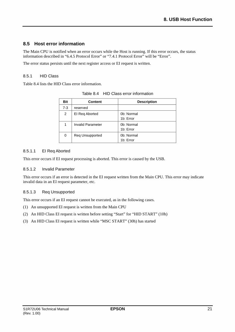
Table 8.4 lists the HID Class error information.
Table 8.4 HID Class error information
Bit Content Description
7-3 reserved
2 EI Req Aborted 0b: Normal 1b: Error
1 Invalid Parameter 0b: Normal 1b: Error
0 Req Unsupported 0b: Normal 1b: Error
8.5.1.1 EI Req Aborted
This error occurs if EI request processing is aborted. This error is caused by the USB.
8.5.1.2 Invalid Parameter
This error occurs if an error is detected in the EI request written from the Main CPU. This error may indicate invalid data in an EI request parameter, etc.
8.5.1.3 Req Unsupported
This error occurs if an EI request cannot be executed, as in the following cases.
(1) An unsupported EI request is written from the Main CPU
(2) An HID Class EI request is written before setting “Start” for “HID START” (10h)
(3) An HID Class EI request is written while “MSC START” (30h) has started

8. USB Host Function
22 EPSON S1R72U06 Technical Manual (Rev. 1.00)
8.5.2 MSC
Table 8.5 lists MSC error information. For more information on the “Block transfers” referenced in the following descriptions, refer to “14. MSC Overview”.
Table 8.5 MSC error information
Bit Content Description
7 Media Not Found 0b: Normal 1b: Error
6 Media Changed 0b: Normal 1b: Error
5 Block Tran Ended 0b: Normal 1b: Error
4 Block Tran Executing 0b: Normal 1b: Error
3 Device Error 0b: Normal 1b: Error
2 EI Req Aborted 0b: Normal 1b: Error
1 Invalid Parameter 0b: Normal 1b: Error
0 Req Unsupported 0b: Normal 1b: Error
8.5.2.1 Media Not Found
This error occurs if no Device Media is detected. No detection is performed when the “STORAGE COMMAND THROUGH” EI request is used.
8.5.2.2 Media Changed
This error occurs if the Device Media has been changed (when the Media was detected). No detection is performed when the “STORAGE COMMAND THROUGH” EI request is used.
8.5.2.3 Block Tran Ended
This error occurs if an EI request that is only valid during block transfers (“BLK WRITE DATA” (3Ah) or “BLK READ DATA” (3Bh)) is detected after the block transfer ends.
8.5.2.4 Block Tran Executing
This error occurs if an EI request that is not valid during block transfers is detected.
8.5.2.5 Device Error
This error occurs if an error caused by USB is detected.
8. USB Host Function
S1R72U06 Technical Manual EPSON 23 (Rev. 1.00)
8.5.2.6 EI Req Aborted
This error occurs if EI request processing is aborted. This error may occur on its own or with any of the errors described in “8.5.2.1 Media Not Found” to “8.5.2.5 Device Error”.
8.5.2.7 Invalid Parameter
This error occurs if an error is detected in the EI request written from the Main CPU. This error may indicate invalid data in an EI request parameter, etc.
8.5.2.8 Req Unsupported
This error occurs when an EI request cannot be executed, as in the following cases.
(1) An unsupported EI request is written from the Main CPU
(2) An MSC EI request is written before setting “Start” for “MSC START” (30h)
(3) An MSC EI request is written while “HID START” (10h) has started
8.6 VBUS control
This LSI incorporates a VBUS supply circuit. It can control a BUS-powered Device provided the current consumed does not exceed the LSI’s supply capacity.
The LSI immediately disconnects the Device if it detects a VBUS overcurrent. Approximately one second after disconnection, the LSI automatically initiates the Device reconnection process. If the VBUS overcurrent remains, the LSI will repeat the disconnection and reconnection process. Note that the VBUS overcurrent detection can be set. Refer to “LSI SETTING” (03h) in the S1R72U06 UART Interface Manual or in the S1R72U06 SPI Interface Manual.
This LSI outputs VBUS when the VBUS control is set to “Start” with the EI request “HID START” (10h) or “MSC START” (30h). This LSI will not output VBUS if VBUS control is set to “Stop”.
8.7 NSF
NSF (No Silent Failures) is a function that notifies the Main CPU of errors detected by the Host. For more information, refer to “11. Notification Function”.
8.8 TPL
TPL (Target Peripheral List) is a list of supported Devices that can be recognized by the Host. Setting TPL renders all Devices unsupported Devices other than those explicitly listed.
A TPL must be created if individual settings are required for the user’s system. For detailed information, refer to the S1R72U06 Development Support Manual.
8.8.1 HID Class TPL
By default, this LSI is set to recognize all HID Class Devices as supported Devices.
8.8.2 MSC TPL
By default, this LSI is set to recognize all bulk-only transport Devices as supported Devices.
8. USB Host Function
24 EPSON S1R72U06 Technical Manual (Rev. 1.00)
8.9 Precautions
8.9.1 For all Classes
(1) Some Devices do not comply with the USB standard or use incorrect descriptor syntax. Such Devices may not be recognized by the LSI.
(2) There may be a risk of VBUS overcurrent occurring when a Device is connected. In particular when using BUS power, the actual current consumed may differ from the descriptor syntax.
(3) Caution is required for the pins described in “10. Setting Function”. Refer to the corresponding section for details.
8.9.2 HID Class
(1) If a Device is disconnected, the LSI clears the Report ID registration information set when the Device was connected. The Report ID registration information must be set each time the Device is connected.
(2) Devices are not supported if the total size for the following descriptors exceeds 512 bytes.
Configuration Descriptor
Interface Descriptor
Endpoint Descriptor
HID Descriptor
8.9.3 MSC
(1) Devices are not supported if the total size for the following descriptors exceeds 512 bytes.
Configuration Descriptor
Interface Descriptor
Endpoint Descriptor
(2) It may not be possible to control MSC Devices that have security functions such as password protection.
(3) The SIO on the LSI also supports HID Class control, and so includes a wide transfer speed (UART) and transfer frequency (SPI) range. It is recommended that the highest practical transfer speed setting be used for the system.

9. USB Device Function
S1R72U06 Technical Manual EPSON 25 (Rev. 1.00)
9. USB Device Function
This LSI incorporates a USB Device function. The details of this function are described below.
9.1 Device Overview
The Device function of this LSI supports HID Class LS and FS (HS not supported).
USB-compliant operations of USB Devices are controlled by the LSI. The Main CPU facilitates control by performing initial setting and event processing.
The following sections describe the settings required by the USB Device function as well as event information, and error information. For information on HID Class, refer to “13. HID Class Overview”.
9.2 Device initial settings
Set the pin shown in Table 9.1 to the initial setting using this LSI’s setting function. For more information, refer to “10. Setting Function”.
Table 9.1 Initial setting
Setting item Pin Setting
DEVICE selection HOSTxDEVICE Low

9. USB Device Function
26 EPSON S1R72U06 Technical Manual (Rev. 1.00)
9.3 Device operation setting
USB Devices define operations and functions using Device information called descriptors. Descriptors may be descriptors for which the format and contents are stipulated by the USB standard and are common for all Devices or may be descriptors specified for an individual Class. This LSI uses HID Descriptor and Report Descriptor for HID Class. The descriptors are shown in Figure 9.1. Physical Descriptors are not supported.
Details such as Device operating conditions should be set in the descriptors. Values indicated as “Fixed” below are specified under the USB standard. For examples of descriptor settings, refer to Appendix A “Descriptor Setting Examples”.
Figure 9.1 Descriptors
This LSI requires Descriptor Header and Report ID Registration Information as special descriptors. Figure 9.2 illustrates the configuration of all descriptors used by the LSI.
Figure 9.2 Descriptor configuration
Common descriptors
Device Descriptor
Configuration Descriptor
Interface Descriptor
Endpoint Descriptor
String Descriptor
HID Descriptor
Report Descriptor
HID Descriptors
Device Descriptor
Configuration Descriptor
Interface Descriptor
Endpoint Descriptor
String Descriptor
HID Descriptor
Report Descriptor
Descriptor Header
Report ID Registration Information
String Language ID Descriptor

9. USB Device Function
S1R72U06 Technical Manual EPSON 27 (Rev. 1.00)
9.3.1 Descriptor Header
Set the header information shown in Table 9.2 for descriptors used with this LSI. Set this Descriptor Header at the beginning of the descriptors. Data (indicated by “xxxxh” in the “Value” column) that needs to be set individually must be entered manually.
wTotalSize: Limit descriptor size to 1,012 bytes or less.
wOffsetForDescriptorInfo: Set the value of the offset from the beginning.
wOffsetForClassPeculiarInfo1: Same as above
wOffsetForClassPeculiarInfo2: Same as above
Note that an error will occur if the settings contain an error when “DOWNLOAD” (02h) is executed.
Table 9.2 Descriptor Header
Content Size
(Byte) Value Description
wTotalSize 2 xxxxh Total size of descriptors including wTotalSize
wDescriptorInfo 2 Fixed Device Descriptor data
wOffsetForDescriptorInfo 2 xxxxh Offset value of Device Descriptor (from wTotalSize to beginning of Device Descriptor)
wClassPeculiarInfo1 2 Fixed Report Descriptor data
wOffsetForClassPeculiarInfo1 2 xxxxh Offset value of Report Descriptor (from wTotalSize to beginning of Report Descriptor)
wClassPeculiarInfo2 2 Fixed Report ID Registration Information data
wOffsetForClassPeculiarInfo2 2 xxxxh Offset value of Report ID Registration Information (from wTotalSize to beginning of Report ID Registration Information)
9. USB Device Function
28 EPSON S1R72U06 Technical Manual (Rev. 1.00)
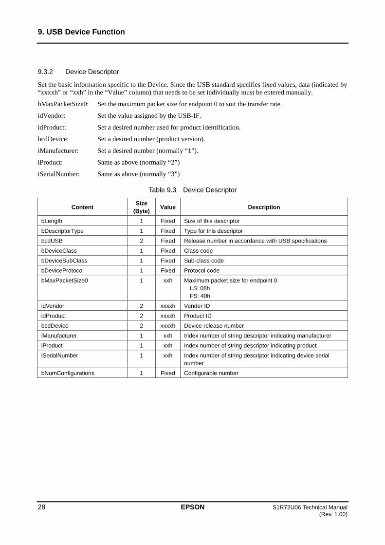
9.3.2 Device Descriptor
Set the basic information specific to the Device. Since the USB standard specifies fixed values, data (indicated by “xxxxh” or “xxh” in the “Value” column) that needs to be set individually must be entered manually.
bMaxPacketSize0: Set the maximum packet size for endpoint 0 to suit the transfer rate.
idVendor: Set the value assigned by the USB-IF.
idProduct: Set a desired number used for product identification.
bcdDevice: Set a desired number (product version).
iManufacturer: Set a desired number (normally “1”).
iProduct: Same as above (normally “2”)
iSerialNumber: Same as above (normally “3”)
Table 9.3 Device Descriptor
Content Size
(Byte) Value Description
bLength 1 Fixed Size of this descriptor
bDescriptorType 1 Fixed Type for this descriptor
bcdUSB 2 Fixed Release number in accordance with USB specifications
bDeviceClass 1 Fixed Class code
bDeviceSubClass 1 Fixed Sub-class code
bDeviceProtocol 1 Fixed Protocol code
bMaxPacketSize0 1 xxh Maximum packet size for endpoint 0 LS: 08h FS: 40h
idVendor 2 xxxxh Vender ID
idProduct 2 xxxxh Product ID
bcdDevice 2 xxxxh Device release number
iManufacturer 1 xxh Index number of string descriptor indicating manufacturer
iProduct 1 xxh Index number of string descriptor indicating product
iSerialNumber 1 xxh Index number of string descriptor indicating device serial number
bNumConfigurations 1 Fixed Configurable number
9. USB Device Function
S1R72U06 Technical Manual EPSON 29 (Rev. 1.00)
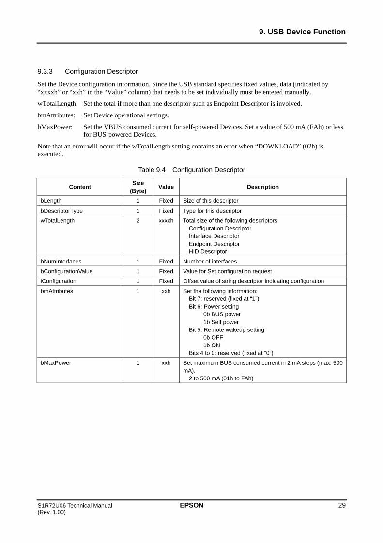
9.3.3 Configuration Descriptor
Set the Device configuration information. Since the USB standard specifies fixed values, data (indicated by “xxxxh” or “xxh” in the “Value” column) that needs to be set individually must be entered manually.
wTotalLength: Set the total if more than one descriptor such as Endpoint Descriptor is involved.
bmAttributes: Set Device operational settings.
bMaxPower: Set the VBUS consumed current for self-powered Devices. Set a value of 500 mA (FAh) or less for BUS-powered Devices.
Note that an error will occur if the wTotalLength setting contains an error when “DOWNLOAD” (02h) is executed.
Table 9.4 Configuration Descriptor
Content Size
(Byte) Value Description
bLength 1 Fixed Size of this descriptor
bDescriptorType 1 Fixed Type for this descriptor
wTotalLength 2 xxxxh Total size of the following descriptors Configuration Descriptor Interface Descriptor Endpoint Descriptor HID Descriptor
bNumInterfaces 1 Fixed Number of interfaces
bConfigurationValue 1 Fixed Value for Set configuration request
iConfiguration 1 Fixed Offset value of string descriptor indicating configuration
bmAttributes 1 xxh Set the following information: Bit 7: reserved (fixed at “1”) Bit 6: Power setting 0b BUS power 1b Self power Bit 5: Remote wakeup setting
0b OFF 1b ON
Bits 4 to 0: reserved (fixed at “0”)
bMaxPower 1 xxh Set maximum BUS consumed current in 2 mA steps (max. 500 mA).
2 to 500 mA (01h to FAh)
9. USB Device Function
30 EPSON S1R72U06 Technical Manual (Rev. 1.00)
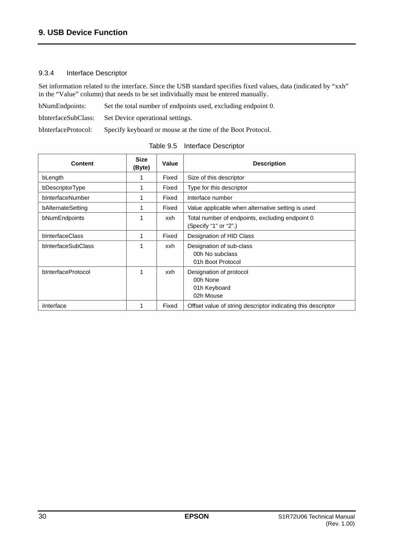
9.3.4 Interface Descriptor
Set information related to the interface. Since the USB standard specifies fixed values, data (indicated by “xxh” in the “Value” column) that needs to be set individually must be entered manually.
bNumEndpoints: Set the total number of endpoints used, excluding endpoint 0.
bInterfaceSubClass: Set Device operational settings.
bInterfaceProtocol: Specify keyboard or mouse at the time of the Boot Protocol.
Table 9.5 Interface Descriptor
Content Size
(Byte) Value Description
bLength 1 Fixed Size of this descriptor
bDescriptorType 1 Fixed Type for this descriptor
bInterfaceNumber 1 Fixed Interface number
bAlternateSetting 1 Fixed Value applicable when alternative setting is used
bNumEndpoints 1 xxh Total number of endpoints, excluding endpoint 0 (Specify “1” or “2”.)
bInterfaceClass 1 Fixed Designation of HID Class
bInterfaceSubClass 1 xxh Designation of sub-class 00h No subclass 01h Boot Protocol
bInterfaceProtocol 1 xxh Designation of protocol 00h None 01h Keyboard 02h Mouse
iInterface 1 Fixed Offset value of string descriptor indicating this descriptor

9. USB Device Function
S1R72U06 Technical Manual EPSON 31 (Rev. 1.00)
9.3.5 HID Descriptor
Set HID Class information. Since the USB standard specifies fixed values, data (indicated by “xxxxh” or “xxh” in the “Value” column) that needs to be set individually must be entered manually.
bCountryCode: Set a code identifying the country, if necessary. For more information on country codes, refer to Appendix C “Country Code”.
wDescriptorLength: Set the Report Descriptor size.
Note that an error will occur if the wDescriptorLength setting differs from the Report Descriptor size when “DOWNLOAD” (02h) is executed.
Table 9.6 HID Descriptor
Content Size
(Byte) Value Description
bLength 1 Fixed Size of this descriptor
bDescriptorType 1 Fixed Type for this descriptor
bcdHID 2 Fixed Release No. depending on HID Class specifications
bCountryCode 1 xxh Country code
bNumDescriptors 1 Fixed Number of Report descriptors
bDescriptorType 1 Fixed Report descriptor type
wDescriptorLength 2 xxxxh Report descriptor size
9. USB Device Function
32 EPSON S1R72U06 Technical Manual (Rev. 1.00)
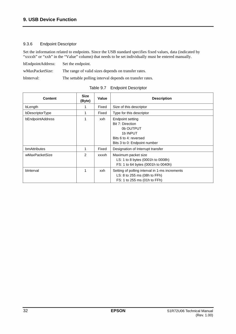
9.3.6 Endpoint Descriptor
Set the information related to endpoints. Since the USB standard specifies fixed values, data (indicated by “xxxxh” or “xxh” in the “Value” column) that needs to be set individually must be entered manually.
bEndpointAddress: Set the endpoint.
wMaxPacketSize: The range of valid sizes depends on transfer rates.
bInterval: The settable polling interval depends on transfer rates.
Table 9.7 Endpoint Descriptor
Content Size
(Byte) Value Description
bLength 1 Fixed Size of this descriptor
bDescriptorType 1 Fixed Type for this descriptor
bEndpointAddress 1 xxh Endpoint setting Bit 7: Direction
0b OUTPUT 1b INPUT
Bits 6 to 4: reversed Bits 3 to 0: Endpoint number
bmAttributes 1 Fixed Designation of Interrupt transfer
wMaxPacketSize 2 xxxxh Maximum packet size LS: 1 to 8 bytes (0001h to 0008h) FS: 1 to 64 bytes (0001h to 0040h)
bInterval 1 xxh Setting of polling interval in 1-ms increments LS: 8 to 255 ms (08h to FFh) FS: 1 to 255 ms (01h to FFh)

9. USB Device Function
S1R72U06 Technical Manual EPSON 33 (Rev. 1.00)
9.3.7 String Language ID Descriptor
Set the language code to be used for String Descriptors. This setting applies to all String Descriptors. Since the USB standard specifies fixed values, data (indicated by “xxxxh” in the “Value” column) that needs to be set individually must be entered manually.
For more information on UNICODE language codes, refer to “2. Compliance”.
Table 9.8 String Language ID Descriptor
Content Size
(Byte) Value Description
bLength 1 Fixed Size of this descriptor
bDescriptorType 1 Fixed Type for this descriptor
wLangID 2 xxxxh UNICODE language code
9.3.8 String Descriptor
Set the string. Since the USB standard specifies fixed values, data (indicated by “xxh” in the “Value” column) that needs to be set individually must be entered manually.
For examples of UNICODE text strings, refer to Appendix B “UNICODE”.
This descriptor is the String Descriptor independently specified by “iManufacturer”, “iProduct”, and “iSerialNumber” described in “9.3.2 Device Descriptor”.
Table 9.9 String Descriptor
Content Size
(Byte) Value Description
bLength 1 xxh Size of this descriptor
bDescriptorType 1 Fixed Type for this descriptor
bString [0] 1 xxh UNICODE character string
...
bString [n] 1 xxh UNICODE character string

9. USB Device Function
34 EPSON S1R72U06 Technical Manual (Rev. 1.00)
9.3.9 Report Descriptor
Set information related to the HID Class Report. The following Item Tags must be set; the other Item Tags are optional. For examples of settings, refer to Appendix D “Report Descriptor Setting Examples”.
USAGE, USAGE_PAGE: Used for HID Class control and for acquiring information by combining USAGE with USAGE_PAGE and using USAGE to access Report.
REPORT_COUNT: Set the number of Reports.
REPORT_SIZE: Set the size of the Reports in bits.
LOGICAL_MINIMUM: Set the minimum value of the Report.
LOGICAL_MAXIMUM: Set the maximum value of the Report.
INPUT (OUTPUT or FEATURE): The Item Tag defined before INPUT determines the INPUT property.
Table 9.10 Report Descriptor
Item Tag Value (Bit)*
Description
USAGE_PAGE 0000 01nn Specify the Usage page.
USAGE 0000 10nn Specify the Usage.
COLLECTION 1010 00nn Grouping of Item Tags defined during END_COLLECTION. COLLECTION may become nested.
USAGE 0000 10nn Specify the Usage. This Usage is correlated with INPUT (OUTPUT, FEATURE) defined thereafter. If the UASGE is a sequential number, it can be defined using USAGE_MINIMUM and USAGE_MAXIMUM.
USAGE_PAGE 0000 01nn Specify the Usage page.
USAGE_MINIMUM 0001 10nn Minimum value of Usage
USAGE_MAXIMUM 0010 10nn Maximum value of Usage
REPORT_ID 1000 01nn Define when using multiple Reports of the same type. For example, when an 8-byte INPUT Report (keyboard) and 4-byte INPUT Report (mouse) are transferred using the same endpoint, this is used to distinguish the data.
REPORT_COUNT 1001 01nn Number of Reports
REPORT_SIZE 0111 01nn Report size
LOGICAL_MINIMUM 0001 01nn Logical minimum value of Report
LOGICAL_MAXIMUM 0010 01nn Logical maximum value of Report
INPUT 1000 00nn Definition of INPUT Report INPUT, OUTPUT, or FEATURE Report can be defined continuously.
OUTPUT 1001 00nn Definition of OUTPUT Report
FEATURE 1011 00nn Definition of FEATURE Report
END_COLLECTION 1100 00nn End of COLLECTION
* Specify the data size of each Item Tag in “nn”.

9. USB Device Function
S1R72U06 Technical Manual EPSON 35 (Rev. 1.00)
9.3.10 Report ID Registration Information
Set Report ID registration information. Data (indicated by “xxxxh” or “xxh” in the “Value” column) that needs to be set individually must be entered manually.
When using multiple Reports, set “bReportType” to “wReportLen” for each Report. The maximum number of Reports is 32 (“bNumInitReports” value). The maximum size for all Report data is 544 bytes (“wReportLen” total).
bNumInitReports: Set the total number of Reports used.
bReportType: Set the Report type.
bReportID: Set the Report ID number (01h to FFh). Set “00h” when this is not used. “00h” cannot be used for Report numbers.
wReportLen: Set the Report data size. When using multiple Report IDs, the size must include a 1-byte Report ID. For more information, refer to “13.3 HID Class Report ID”.
Table 9.11 Report ID Registration Information
Content Size
(Byte) Value Description
bNumHID_Interfaces 1 Fixed Number of interfaces
bInterfaceNo 1 Fixed Interface number
bNumInitReports 1 xxh Total number of Reports (max. 32)
bReserve 1 Fixed reserved
bReportType 1 xxh Report type 00h: reserved 01h: Input Report 02h: Output Report 03h: Feature Report 04h to FFh: reserved
bReportID 1 xxh Report ID number 00h: Not used 01h to FFh: ID number
wReportLen 2 xxxxh Size of Report data (max. 257 bytes) 1 to 257 bytes (0001h to 0101h)

9. USB Device Function
36 EPSON S1R72U06 Technical Manual (Rev. 1.00)
9.4 Device event information
The Main CPU is notified if an event occurs during Device operations. Table 9.12 lists the event information issued by the LSI. For more information, refer to “6.3 UART event control” and “7.3 SPI event control”.
Table 9.12 Device event information
Bit Content Description
7 USB Com Status 0b: Inactive 1b: Active
6 USB Suspend Status 0b: Resume (Event) 1b: Suspend (Event)
5 Detect Reset 0b: Normal 1b: Detect (Event)
4 Protocol Mode Change 0b: Normal 1b: Receive (Event)
3 Rcv Feature Report 0b: Normal 1b: Receive (Event)
2 Rcv Output Report 0b: Normal 1b: Receive (Event)
1 CD Change 0b: Normal 1b: Change (Event)
0 CD (Connection Detect)
0b: Disconnect 1b: Connect
9.4.1 USB Com Status
This indicates that this LSI is connected to or disconnected from a Host. “Active” for this status indicates a physical connection.
9.4.2 USB Suspend Status
An event occurs when the USB state changes from “Resume Suspend” or from “Suspend Resume”. This event is not cleared in the manner described in “9.4.9 Event Clear”, and the USB BUS state for the time at which the event information was read is indicated. Note that “Resume” indicates an “Active” state after the event occurs.
9.4.3 Detect Reset
This event is generated when USB BUS reset is detected while CD (refer to “9.4.8 CD”) is at “Connect”.
9.4.4 Protocol Mode Change
This event is generated when protocol mode settings are received from the Host. The Main CPU should check the protocol using the “GET PROTOCOL MODE” (25h) EI request.
9. USB Device Function
S1R72U06 Technical Manual EPSON 37 (Rev. 1.00)
9.4.5 Rcv Feature Report
This event is generated when data is received from the Host via Feature Report transfer. When the XIRQ_EVENT pin is set to “disable”, this event is not generated, since data is transferred to the Main CPU as soon as reception of data from the Host is complete.
9.4.6 Rcv Output Report
This event is generated when data is received from the Host via Output Report transfer. As described in “9.4.5 Rcv Feature Report”, this event is not generated when the XIRQ_EVENT pin is set to “disable”.
9.4.7 CD Change
This event is generated when the CD status (refer to “9.4.8 CD”) changes.
9.4.8 CD
The status changes when this LSI is connected to or disconnected from the Host and USB processing is completed. For more information on connection and disconnection, refer to the S1R72U06 Application Note.
9.4.9 Event Clear
For detailed information on event clear conditions, refer to the sections below. For information on the status change of the XIRQ_EVENT pin, refer to the S1R72U06 UART Interface Manual or S1R72U06 SPI Interface Manual.
9.4.9.1 UART clear conditions
When the XIRQ_EVENT pin is set to “enable”, event information is cleared when a “GET EVENT” (F0h) EI request is written from the Main CPU. When the pin is set to “disable”, event information is cleared once it is transferred to the Main CPU.
9.4.9.2 SPI clear conditions
When the Main CPU acquires event information “Event” (80h), it is cleared.

9. USB Device Function
38 EPSON S1R72U06 Technical Manual (Rev. 1.00)
9.5 Device error information
The Main CPU is notified when an error occurs while the Device is running. Table 9.13 lists the error information issued by the LSI. If this error occurs, the status information described in “6.4.5 Protocol Error” or “7.4.1 Protocol Error” will be “Error”.
The error status persists until the next register access or EI request is written.
Table 9.13 Device error information
Bit Content Description
7 HID Start Failed 0b: Normal 1b: Error
6 HID Req Failed 0b: Normal 1b: Error
5-3 reserved
2 EI Req Aborted 0b: Normal 1b: Error
1 Invalid Parameter 0b: Normal 1b: Error
0 Req Unsupported 0b: Normal 1b: Error
9.5.1 HID Start Failed
This error occurs when “Start” processing for “HID START” (10h) cannot be executed. This error may indicate that the descriptor setting or Report information initial setting is invalid.
9.5.2 HID Req Failed
This error occurs when data transfer processing with the Host cannot be executed. This error may indicate that the USB is in a Suspend state.
9.5.3 EI Req Aborted
This error occurs if EI request processing is aborted. This error is caused by the USB.
9.5.4 Invalid Parameter
This error occurs if an error is detected in the EI request written from the Main CPU. This error may indicate invalid data in an EI request parameter, etc.
9.5.5 Req Unsupported
This error occurs if an EI request cannot be executed, as in the following cases.
(1) An unsupported EI request is written from the Main CPU.
(2) An HID Class EI request is written before setting “Start” for “HID START” (10h).
9. USB Device Function
S1R72U06 Technical Manual EPSON 39 (Rev. 1.00)
9.6 Precautions
(1) If not recognized or recognized as an “unknown device” when connected to the Host, this is likely to be due to a descriptor syntax error. The descriptor syntax may also differ from the control settings (LS is specified by “HID START” when set to FS by descriptor).
(2) When controlling Devices complying with the USB standard, they may be suspended by the Host. If a Suspend event occurs, the Main CPU should process as described in “13.2 HID Class time-related regulations”.
(3) The USB standard stipulates that resetting from Suspend should be performed using Resume processing, but some Hosts may use BUS resetting. To support such Hosts, disconnection and connection processing is used for reconnection.
(4) Caution is required for the pins described in “10. Setting Function”. Refer to the corresponding section for details.

10. Setting Function
40 EPSON S1R72U06 Technical Manual (Rev. 1.00)
10. Setting Function
This LSI uses the setting function to enter initial settings and control operations. Refer to the following table for detailed information.
Table 10.1 Setting function
Pin Content Description
SPIxUART Low: UART High: SPI
Cannot be changed while power is on.
HOSTxDEVICE Low: DEVICE High: HOST
A hardware reset occurs if the setting changes while power is being supplied.
WAKEUP Low High: WAKEUP Wakeup occurs at the rising edge of the change from Low to High.
INIT_BAUD Low: 300 bps High: 9,600 bps
Changes in this setting are not possible while power is being supplied.
10.1 SPIxUART
Set the SIO function UART or SPI. For detailed information, refer to “6. UART Function” or “7. SPI Function”.
10.2 HOSTxDEVICE
Set the USB function Host or Device. If this setting changes while power is supplied, a forced hardware reset is generated. Be careful to minimize the effects of external noise and other factors. For detailed information on the USB function, refer to “8. USB Host Function” or “9. USB Device Function”.
10.3 WAKEUP
This is used to change the status of this LSI from SLEEP to ACTIVE. Since this pin is activated by a rising edge, set to “Low High Low”. Keep at “Low” during normal use. If this pin is set to “Low High Low” while in the ACTIVE state and this LSI is set to SLEEP, the rising edge is retained; thus, the LSI status will not change to SLEEP. Be careful to minimize the effects of external noise and other factors.
For information on using this pin, refer to “Power management” in the S1R72U06 Application Note.
10.4 INIT_BAUD
Set the UART initial baud rate to 9,600 or 300 bps.
This pin setting applies to UART only and should be set to “Low” for SPI.

11. Notification Function
S1R72U06 Technical Manual EPSON 41 (Rev. 1.00)
11. Notification Function
The notification function is used to notify the Main CPU of the LSI status and the USB NSF (notification function enabled for USB Host only). Details are given below.
Table 11.1 Notification function
Pin Content Description
SIO_READY Low: Not Ready High: Ready
Indicates the SIO status.
UART Low: Busy High: Idle
Indicates the LSI status. XIRQ_STATUS
SPI Low: Change High: Not Change
Indicates the LSI status change.
XIRQ_EVENT Low: EVENT High: Normal
Indicates the event status.
TPL Low: Normal High: Error
NSF: Unsupported Device
ManyDev Low: Normal High: Error
NSF: Too Many Devices
ManyHub Low: Normal High: Error
NSF: Too Many Hubs
VBUS_Cur Low: Normal High: Error
NSF: VBUS Over Current
11.1 SIO_READY
This switches to “High” when SIO transfer is possible. It is “Low” in states in which SIO transfer is not possiblefor example, before a hardware reset or in the Sleep state.
11.2 XIRQ_STATUS
Specifics of this pin depend on the SIO used.
11.2.1 UART
Changes to “Low” if the internal state of the LSI changes to “Busy”. Changes to “High” for “Idle”. For more information, refer to “6.4.6 Condition”.
11.2.2 SPI
Indicates LSI state changes. For more information, refer to “7.4.3 Condition”.
(1) Changes to “Low” if the state changes from “Busy Idle” or from “Busy TranRdy”.
(2) Changes to “High” when status information is acquired by the Main CPU. “High” is maintained if no state change occurs.

11. Notification Function
42 EPSON S1R72U06 Technical Manual (Rev. 1.00)
11.3 XIRQ_EVENT
This LSI includes two types of events: protocol events and Sleep state events.
11.3.1 PROTOCOL EVENT
PROTOCOL EVENTS are the events described in S1R72U06 UART Interface Manual or S1R72U06 SPI Interface Manual. Note that the details will vary for this pin depending on the SIO used.
11.3.1.1 UART
The pin output can be set to either “enable” or “disable”. When set to “enable”, the pin changes to “Low” if an event occurs and to “High” if the “GET EVENT” (F0h) EI request is written from the Main CPU. For detailed information, refer to “6.3 UART event control”.
11.3.1.2 SPI
The pin changes to “Low” if an event occurs and to “High” if the Main CPU acquires event information “Event” (80h). For detailed information, refer to “7.3 SPI event control”.
11.3.2 SLEEP EVENT
Events in the Sleep state change the pin to “Low” under the following conditions. The status changes to “High” if the LSI is Wakeup.
USB Host
- When a Device is connected
- When a Device is disconnected
- When a Device Remote Wakeup is detected
USB Device
- When connected to the Host
- When disconnected from a Host or when USB BUS reset or resume has been detected
11.4 TPL
“Error” is issued if an unsupported Device is detected. The status reverts to “Normal” when the unsupported Device is disconnected.
11.5 ManyDev
“Error” is issued if two or more Devices are detected. The status reverts to “Normal” when one or no Device is connected.
11. Notification Function
S1R72U06 Technical Manual EPSON 43 (Rev. 1.00)
11.6 ManyHub
“Error” is issued if two or more Devices with a built-in HUB are detected. The status reverts to “Normal” when one or no Device is connected.
11.7 VBUS_Cur
“Error” is issued if a VBUS overcurrent condition is detected. For detailed information, refer to “8.6 VBUS control”.
12. Development Support Functions
44 EPSON S1R72U06 Technical Manual (Rev. 1.00)
12. Development Support Functions
This LSI incorporates functions to confirm operating conditions and to support the USB authentication and download function. For detailed information, refer to the S1R72U06 Development Support Manual.
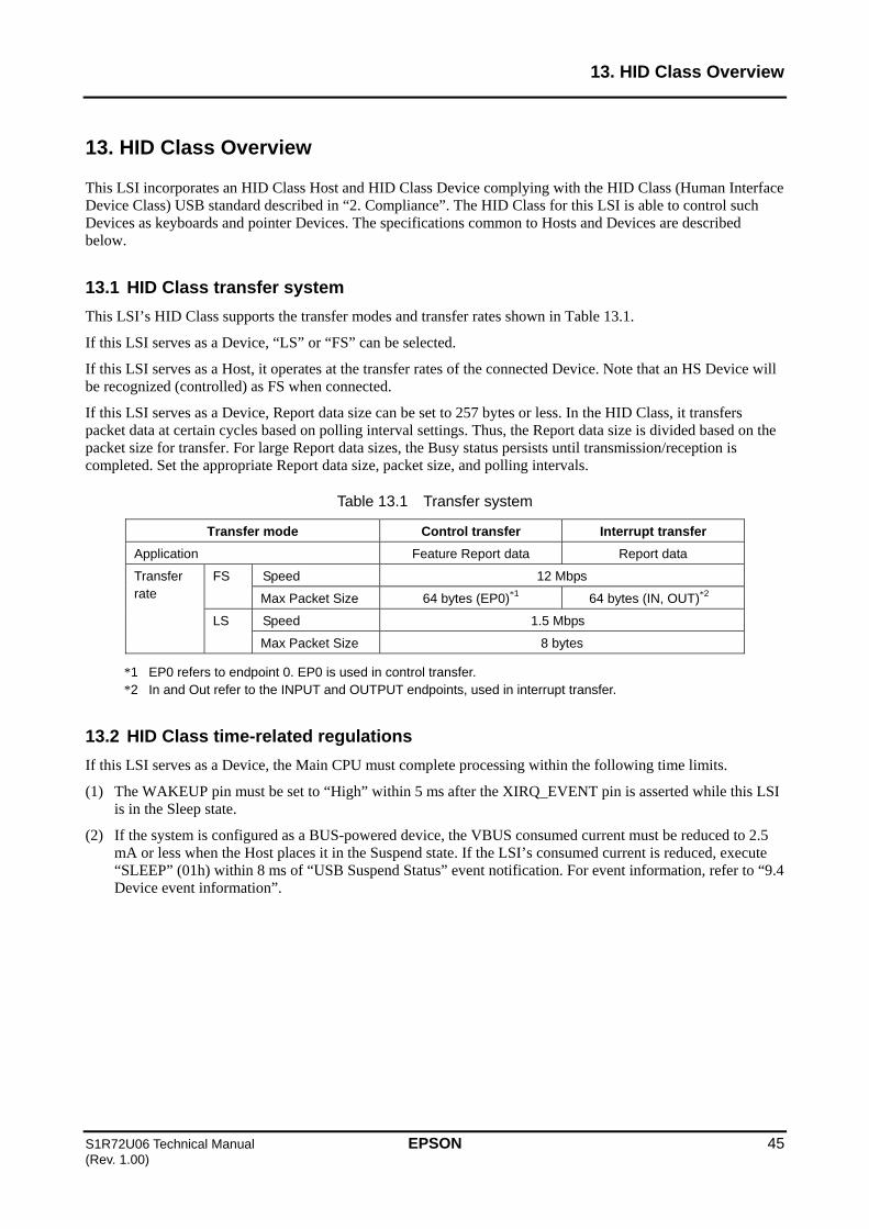
13. HID Class Overview
S1R72U06 Technical Manual EPSON 45 (Rev. 1.00)
13. HID Class Overview
This LSI incorporates an HID Class Host and HID Class Device complying with the HID Class (Human Interface Device Class) USB standard described in “2. Compliance”. The HID Class for this LSI is able to control such Devices as keyboards and pointer Devices. The specifications common to Hosts and Devices are described below.
13.1 HID Class transfer system
This LSI’s HID Class supports the transfer modes and transfer rates shown in Table 13.1.
If this LSI serves as a Device, “LS” or “FS” can be selected.
If this LSI serves as a Host, it operates at the transfer rates of the connected Device. Note that an HS Device will be recognized (controlled) as FS when connected.
If this LSI serves as a Device, Report data size can be set to 257 bytes or less. In the HID Class, it transfers packet data at certain cycles based on polling interval settings. Thus, the Report data size is divided based on the packet size for transfer. For large Report data sizes, the Busy status persists until transmission/reception is completed. Set the appropriate Report data size, packet size, and polling intervals.
Table 13.1 Transfer system
Transfer mode Control transfer Interrupt transfer
Application Feature Report data Report data
Speed 12 Mbps FS
Max Packet Size 64 bytes (EP0)*1 64 bytes (IN, OUT)*2
Speed 1.5 Mbps
Transfer rate
LS
Max Packet Size 8 bytes
*1 EP0 refers to endpoint 0. EP0 is used in control transfer. *2 In and Out refer to the INPUT and OUTPUT endpoints, used in interrupt transfer.
13.2 HID Class time-related regulations
If this LSI serves as a Device, the Main CPU must complete processing within the following time limits.
(1) The WAKEUP pin must be set to “High” within 5 ms after the XIRQ_EVENT pin is asserted while this LSI is in the Sleep state.
(2) If the system is configured as a BUS-powered device, the VBUS consumed current must be reduced to 2.5 mA or less when the Host places it in the Suspend state. If the LSI’s consumed current is reduced, execute “SLEEP” (01h) within 8 ms of “USB Suspend Status” event notification. For event information, refer to “9.4 Device event information”.

13. HID Class Overview
46 EPSON S1R72U06 Technical Manual (Rev. 1.00)
13.3 HID Class Report ID
ID can be set to distinguish the Feature Report/Report data used in the HID Class. ID allows control of a keyboard and mouse with a single endpoint.
13.3.1 Data using Report ID
When Report ID is used, a 1-byte Report ID is added to the beginning of the data. The data size must include the 1-byte Report ID. For more information on data size, refer to “9.3.10 Report ID Registration Information”.
The Main CPU should add a 1-byte Report ID to the data to be written.
Data read by the Main CPU has a 1-byte Report ID added by the USB.
Figure 13.1 shows data using Report ID.
Figure 13.1 Data using Report ID
13.3.2 Data not using Report ID
Only the data is used when no Report ID is used.
Figure 13.2 shows data lacking a Report ID.
Figure 13.2 Data not using Report ID
… datan
Data size
ReportID
data0
data1
… datan
Data size
data0
data1

13. HID Class Overview
S1R72U06 Technical Manual EPSON 47 (Rev. 1.00)
13.4 HID Class protocols
13.4.1 Boot Protocol
Boot Protocol is a protocol specified by the USB standard. When using Boot Protocol, “SEND REPORT” (22h) should be written or “RECV REPORT” (23h) should be read using the data format described below.
Figures 13.3 and 13.4 show the keyboard data format.
Byte
Name
7
K6
6
K5
5
K4
4
K3
3
K2
2
K1
1
R
8
M
1-key input: Sets value to K12-key input: Sets values to K1 and K2...
6-key input: Sets values to K1 to K6
00h (fixed)
Bit7: Right GUI (windows) KeyBit6: Right Alt KeyBit5: Right Shift KeyBit4: Right Control KeyBit3: Left GUI (windows) KeyBit2: Left Alt KeyBit1: Left Shift KeyBit0: Left Control Key
Figure 13.3 Keyboard Input
Figure 13.4 Keyboard Output
Figure 13.5 shows the mouse data format.
Figure 13.5 Mouse Input
Byte
Name
1
LED
Bit 7-5: 000b (fixed)Bit 4: Kana LEDBit 3: Compose LEDBit 2: Scroll Lock LEDBit 1: Caps Lock LEDBit 0: Num Lock LED
Byte
Name
32
Y
1
XB
Y-axis relative movement
X-axis relative movement
Bit 7-3: 00000b (fixed) Bit 2: Button3 Bit 1: Button2 Bit 0: Button1
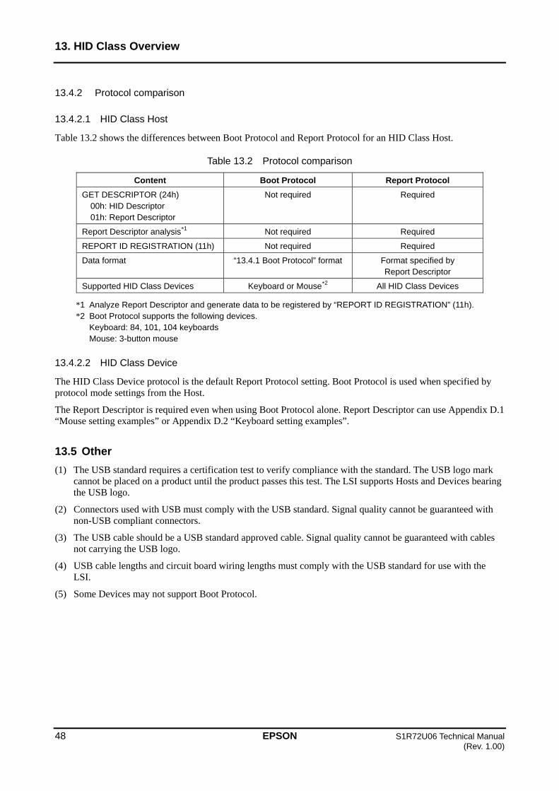
13. HID Class Overview
48 EPSON S1R72U06 Technical Manual (Rev. 1.00)
13.4.2 Protocol comparison
13.4.2.1 HID Class Host
Table 13.2 shows the differences between Boot Protocol and Report Protocol for an HID Class Host.
Table 13.2 Protocol comparison
Content Boot Protocol Report Protocol
GET DESCRIPTOR (24h) 00h: HID Descriptor 01h: Report Descriptor
Not required Required
Report Descriptor analysis*1 Not required Required
REPORT ID REGISTRATION (11h) Not required Required
Data format “13.4.1 Boot Protocol” format Format specified by Report Descriptor
Supported HID Class Devices Keyboard or Mouse*2 All HID Class Devices
*1 Analyze Report Descriptor and generate data to be registered by “REPORT ID REGISTRATION” (11h). *2 Boot Protocol supports the following devices.
Keyboard: 84, 101, 104 keyboards Mouse: 3-button mouse
13.4.2.2 HID Class Device
The HID Class Device protocol is the default Report Protocol setting. Boot Protocol is used when specified by protocol mode settings from the Host.
The Report Descriptor is required even when using Boot Protocol alone. Report Descriptor can use Appendix D.1 “Mouse setting examples” or Appendix D.2 “Keyboard setting examples”.
13.5 Other
(1) The USB standard requires a certification test to verify compliance with the standard. The USB logo mark cannot be placed on a product until the product passes this test. The LSI supports Hosts and Devices bearing the USB logo.
(2) Connectors used with USB must comply with the USB standard. Signal quality cannot be guaranteed with non-USB compliant connectors.
(3) The USB cable should be a USB standard approved cable. Signal quality cannot be guaranteed with cables not carrying the USB logo.
(4) USB cable lengths and circuit board wiring lengths must comply with the USB standard for use with the LSI.
(5) Some Devices may not support Boot Protocol.
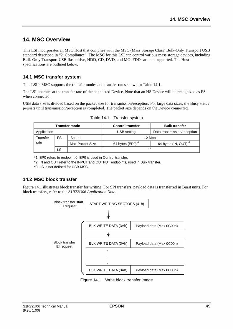
14. MSC Overview
S1R72U06 Technical Manual EPSON 49 (Rev. 1.00)
14. MSC Overview
This LSI incorporates an MSC Host that complies with the MSC (Mass Storage Class) Bulk-Only Transport USB standard described in “2. Compliance”. The MSC for this LSI can control various mass storage devices, including Bulk-Only Transport USB flash drive, HDD, CD, DVD, and MO. FDDs are not supported. The Host specifications are outlined below.
14.1 MSC transfer system
This LSI’s MSC supports the transfer modes and transfer rates shown in Table 14.1.
The LSI operates at the transfer rate of the connected Device. Note that an HS Device will be recognized as FS when connected.
USB data size is divided based on the packet size for transmission/reception. For large data sizes, the Busy status persists until transmission/reception is completed. The packet size depends on the Device connected.
Table 14.1 Transfer system
Transfer mode Control transfer Bulk transfer
Application USB setting Data transmission/reception
Speed 12 Mbps FS
Max Packet Size 64 bytes (EP0)*1 64 bytes (IN, OUT)*2
Transfer rate
LS *3
*1 EP0 refers to endpoint 0. EP0 is used in Control transfer. *2 IN and OUT refer to the INPUT and OUTPUT endpoints, used in Bulk transfer. *3 LS is not defined for USB MSC.
14.2 MSC block transfer
Figure 14.1 illustrates block transfer for writing. For SPI transfers, payload data is transferred in Burst units. For block transfers, refer to the S1R72U06 Application Note.
Figure 14.1 Write block transfer image
START WRITING SECTORS (41h)Block transfer start EI request
BLK WRITE DATA (3Ah)
BLK WRITE DATA (3Ah)
.
.
.
BLK WRITE DATA (3Ah) Payload data (Max 0C00h)
Block transfer EI request
Payload data (Max 0C00h)
Payload data (Max 0C00h)
14. MSC Overview
50 EPSON S1R72U06 Technical Manual (Rev. 1.00)
14.3 Other
(1) The USB standard includes certification tests for verifying compliance with the standard, and Devices that pass these tests are allowed to carry the USB logo. The LSI supports Hosts and Devices that carry the USB logo.
(2) Connectors used with USB must comply with the USB standard. Signal quality cannot be guaranteed with non-USB compliant connectors.
(3) The USB cable should be a USB standard approved cable. Signal quality cannot be guaranteed with cables not carrying the USB logo.
(4) USB cable lengths and circuit board wiring lengths must comply with the USB standard for use with the LSI.
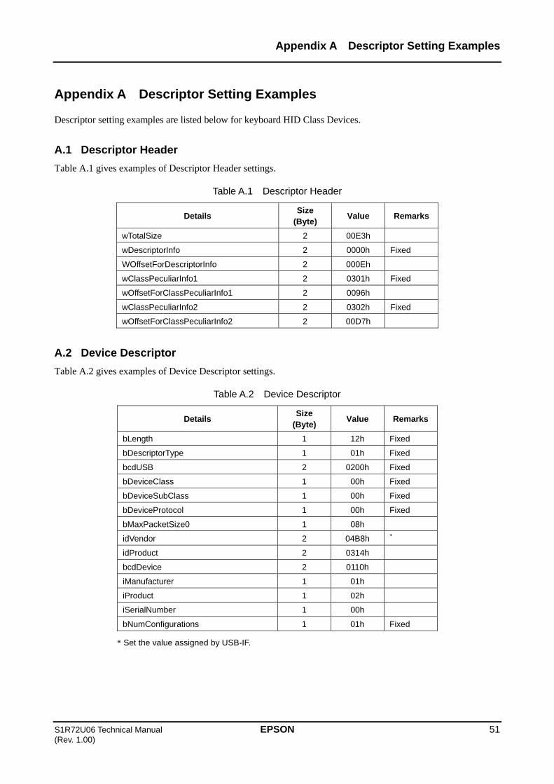
Appendix A Descriptor Setting Examples
S1R72U06 Technical Manual EPSON 51 (Rev. 1.00)
Appendix A Descriptor Setting Examples
Descriptor setting examples are listed below for keyboard HID Class Devices.
A.1 Descriptor Header
Table A.1 gives examples of Descriptor Header settings.
Table A.1 Descriptor Header
Details Size
(Byte) Value Remarks
wTotalSize 2 00E3h
wDescriptorInfo 2 0000h Fixed
WOffsetForDescriptorInfo 2 000Eh
wClassPeculiarInfo1 2 0301h Fixed
wOffsetForClassPeculiarInfo1 2 0096h
wClassPeculiarInfo2 2 0302h Fixed
wOffsetForClassPeculiarInfo2 2 00D7h
A.2 Device Descriptor
Table A.2 gives examples of Device Descriptor settings.
Table A.2 Device Descriptor
Details Size
(Byte) Value Remarks
bLength 1 12h Fixed
bDescriptorType 1 01h Fixed
bcdUSB 2 0200h Fixed
bDeviceClass 1 00h Fixed
bDeviceSubClass 1 00h Fixed
bDeviceProtocol 1 00h Fixed
bMaxPacketSize0 1 08h
idVendor 2 04B8h *
idProduct 2 0314h
bcdDevice 2 0110h
iManufacturer 1 01h
iProduct 1 02h
iSerialNumber 1 00h
bNumConfigurations 1 01h Fixed
* Set the value assigned by USB-IF.

Appendix A Descriptor Setting Examples
52 EPSON S1R72U06 Technical Manual (Rev. 1.00)
A.3 Configuration Descriptor
Table A.3 gives examples of Configuration Descriptor settings.
Table A.3 Configuration Descriptor
Details Size
(Byte) Value Remarks
bLength 1 09h Fixed
bDescriptorType 1 02h Fixed
wTotalLength 2 0022h
bNumInterfaces 1 01h Fixed
bConfigurationValue 1 01h Fixed
iConfiguration 1 00h Fixed
bmAttributes 1 E0h
bMaxPower 1 31h
A.4 Interface Descriptor
Table A.4 gives examples of Interface Descriptor settings.
Table A.4 Interface Descriptor
Details Size
(Byte) Value Remarks
bLength 1 09h Fixed
bDescriptorType 1 04h Fixed
bInterfaceNumber 1 00h Fixed
bAlternateSetting 1 00h Fixed
bNumEndpoints 1 01h
bInterfaceClass 1 03h Fixed
bInterfaceSubClass 1 01h
bInterfaceProtocol 1 01h
iInterface 1 00h Fixed
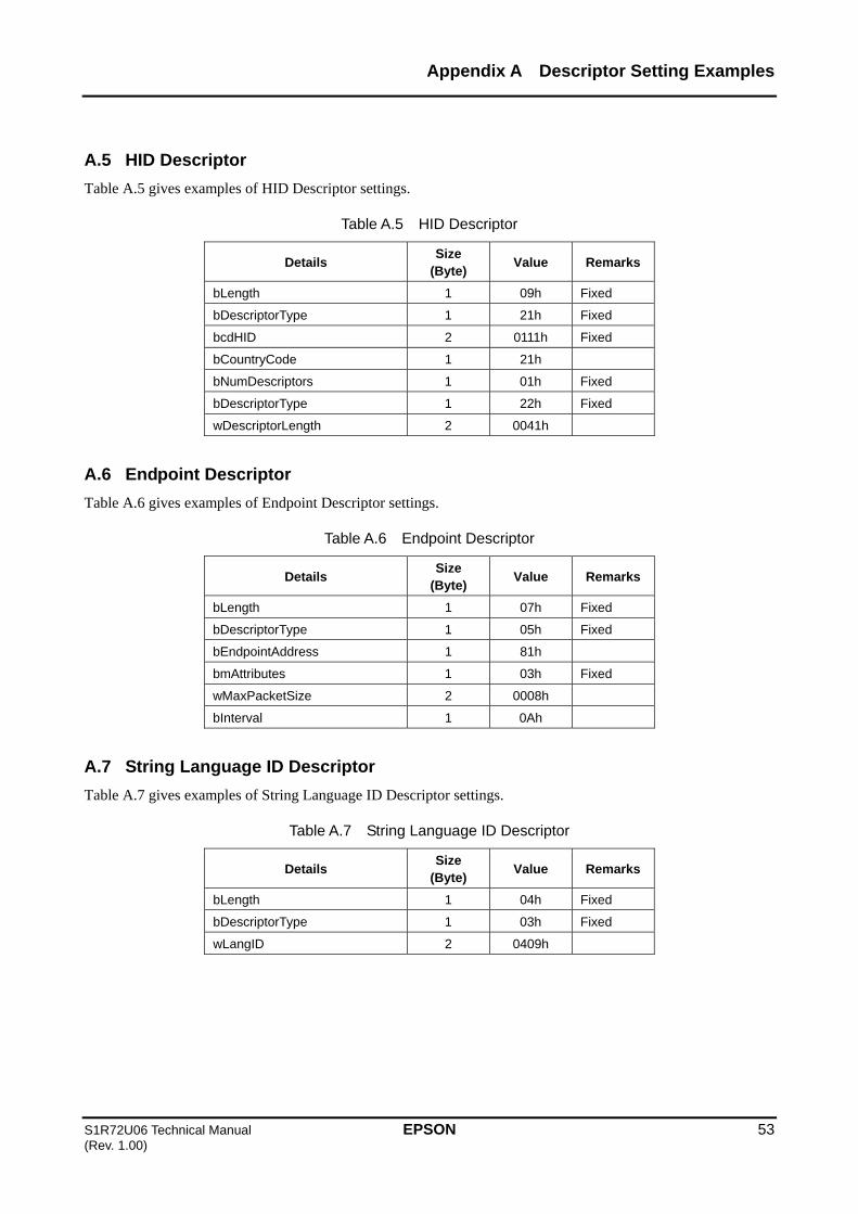
Appendix A Descriptor Setting Examples
S1R72U06 Technical Manual EPSON 53 (Rev. 1.00)
A.5 HID Descriptor
Table A.5 gives examples of HID Descriptor settings.
Table A.5 HID Descriptor
Details Size
(Byte) Value Remarks
bLength 1 09h Fixed
bDescriptorType 1 21h Fixed
bcdHID 2 0111h Fixed
bCountryCode 1 21h
bNumDescriptors 1 01h Fixed
bDescriptorType 1 22h Fixed
wDescriptorLength 2 0041h
A.6 Endpoint Descriptor
Table A.6 gives examples of Endpoint Descriptor settings.
Table A.6 Endpoint Descriptor
Details Size
(Byte) Value Remarks
bLength 1 07h Fixed
bDescriptorType 1 05h Fixed
bEndpointAddress 1 81h
bmAttributes 1 03h Fixed
wMaxPacketSize 2 0008h
bInterval 1 0Ah
A.7 String Language ID Descriptor
Table A.7 gives examples of String Language ID Descriptor settings.
Table A.7 String Language ID Descriptor
Details Size
(Byte) Value Remarks
bLength 1 04h Fixed
bDescriptorType 1 03h Fixed
wLangID 2 0409h

Appendix A Descriptor Setting Examples
54 EPSON S1R72U06 Technical Manual (Rev. 1.00)
A.8 String Descriptor
Tables A.8 and A.9 give examples of String Descriptor settings.
Table A.8 String Descriptor
Details Size
(Byte) Value Remarks
bLength 1 24h
bDescriptorType 1 03h Fixed
bString [0] 1 53h
bString [1] 1 00h
...
bString [32] 1 2Eh
bString [33] 1 00h
Table A.9 String Descriptor
Details Size
(Byte) Value Remarks
bLength 1 2Ch
bDescriptorType 1 03h Fixed
bString [0] 1 53h
bString [1] 1 00h
...
bString [40] 1 64h
bString [41] 1 00h

Appendix A Descriptor Setting Examples
S1R72U06 Technical Manual EPSON 55 (Rev. 1.00)
A.9 Report Descriptor
Table A.10 gives examples of Report Descriptor settings.
Table A.10 Report Descriptor
Item Tag Size
(Byte) Value Remarks
USAGE_PAGE 2 05h, 01h
USAGE 2 09h, 06h
COLLECTION 2 A1h, 01h
USAGE 2 05h, 07h
USAGE_MINIMUM 2 19h, E0h
USAGE_MAXIMUM 2 29h, E7h
LOGICAL_MINIMUM 2 15h, 00h
LOGICAL_MAXIMUM 2 25h, 01h
REPORT_SIZE 2 75h, 01h
REPORT_COUNT 2 95h, 08h
INPUT 2 81h, 02h
REPORT_COUNT 2 95h, 01h
REPORT_SIZE 2 75h, 08h
INPUT 2 81h, 01h
REPORT_COUNT 2 95h, 03h
REPORT_SIZE 2 75h, 01h
USAGE PAGE 2 05h, 08h
USAGE_MINIMUM 2 19h, 01h
USAGE_MAXIMUM 2 29h, 03h
OUTPUT 2 91h, 02h
REPORT_COUNT 2 95h, 05h
REPORT_SIZE 2 75h, 01h
OUTPUT 2 91h, 01h
REPORT_COUNT 2 95h, 06h
REPORT_SIZE 2 75h, 08h
LOGICAL_MINIMUM 2 15h, 00h
LOGICAL_MAXIMUM 3 26h, FFh, 00h
USAGE PAGE 2 05h, 07h
USAGE_MINIMUM 2 19h, 00h
USAGE_MAXIMUM 3 2A, FFh, 00h
INPUT 2 81h, 00h
END_COLLECTION 1 C0h
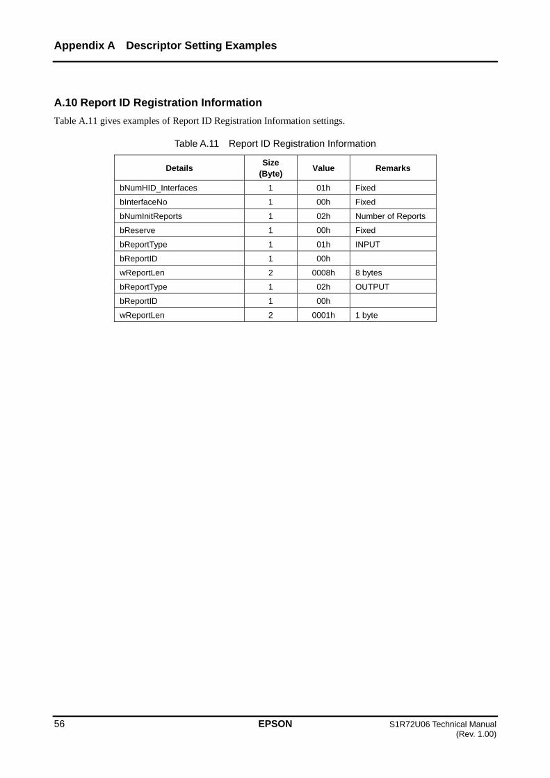
Appendix A Descriptor Setting Examples
56 EPSON S1R72U06 Technical Manual (Rev. 1.00)
A.10 Report ID Registration Information
Table A.11 gives examples of Report ID Registration Information settings.
Table A.11 Report ID Registration Information
Details Size
(Byte) Value Remarks
bNumHID_Interfaces 1 01h Fixed
bInterfaceNo 1 00h Fixed
bNumInitReports 1 02h Number of Reports
bReserve 1 00h Fixed
bReportType 1 01h INPUT
bReportID 1 00h
wReportLen 2 0008h 8 bytes
bReportType 1 02h OUTPUT
bReportID 1 00h
wReportLen 2 0001h 1 byte
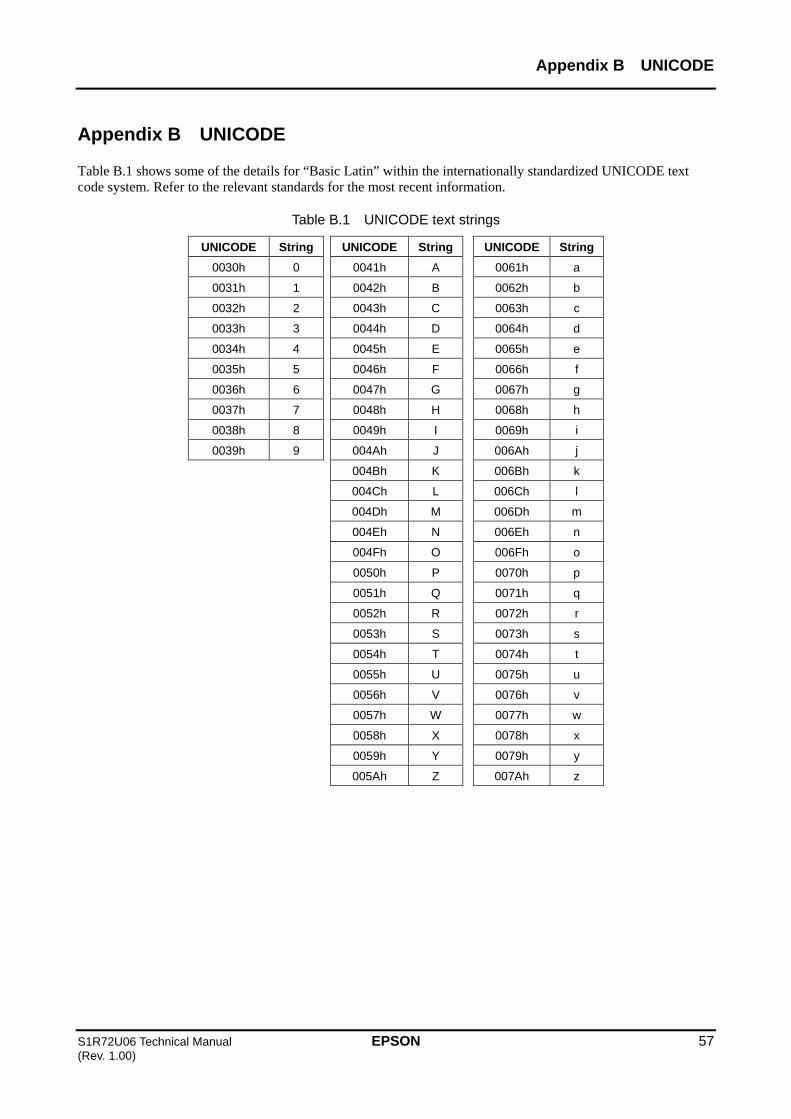
Appendix B UNICODE
S1R72U06 Technical Manual EPSON 57 (Rev. 1.00)
Appendix B UNICODE
Table B.1 shows some of the details for “Basic Latin” within the internationally standardized UNICODE text code system. Refer to the relevant standards for the most recent information.
Table B.1 UNICODE text strings
UNICODE String UNICODE String UNICODE String
0030h 0 0041h A 0061h a
0031h 1 0042h B 0062h b
0032h 2 0043h C 0063h c
0033h 3 0044h D 0064h d
0034h 4 0045h E 0065h e
0035h 5 0046h F 0066h f
0036h 6 0047h G 0067h g
0037h 7 0048h H 0068h h
0038h 8 0049h I 0069h i
0039h 9 004Ah J 006Ah j
004Bh K 006Bh k
004Ch L 006Ch l
004Dh M 006Dh m
004Eh N 006Eh n
004Fh O 006Fh o
0050h P 0070h p
0051h Q 0071h q
0052h R 0072h r
0053h S 0073h s
0054h T 0074h t
0055h U 0075h u
0056h V 0076h v
0057h W 0077h w
0058h X 0078h x
0059h Y 0079h y
005Ah Z 007Ah z

Appendix C Country Code
58 EPSON S1R72U06 Technical Manual (Rev. 1.00)
Appendix C Country Code
Table C.1 lists HID Descriptor country codes for reference. Refer to the USB standard for the most recent information.
Table C.1 Country Code
Code Country Code Country Code Country
00h Not Supported 10h Korean 20h UK
01h Arabic 11h Latin American 21h US
02h Belgian 12h Netherlands/Dutch 22h Yugoslavia
03h Canadian-Bilingual 13h Norwegian 23h Turkish-F
04h Canadian-French 14h Persian (Farsi) 24h-FFh Reserved
05h Czech Republic 15h Poland
06h Danish 16h Portuguese
07h Finnish 17h Russia
08h French 18h Slovakia
09h German 19h Spanish
0Ah Greek 1Ah Swedish
0Bh Hebrew 1Bh Swiss/French
0Ch Hungary 1Ch Swiss/German
0Dh International (ISO) 1Dh Switzerland
0Eh Italian 1Eh Taiwan
0Fh Japan (Katakana)
1Fh Turkish-Q

Appendix D Report Descriptor Setting Examples
S1R72U06 Technical Manual EPSON 59 (Rev. 1.00)
Appendix D Report Descriptor Setting Examples
The following sections describe various examples of Report Descriptor settings for a mouse, keyboard, and vendor-defined HID Class. Precise specifications are not provided for certain Report Descriptor settings to ensure flexibility even within the USB standard. Refer to the setting examples for more information.
D.1 Mouse setting examples
Table D.1 lists examples of mouse Report Descriptor settings. The “Group” column refers to the group setting for each Item Tag.
Table D.1 Mouse Report Descriptor
Item Tag Size
(Byte) Value Description Group
USAGE_PAGE 2 05h, 01h Generic Desktop Controls
USAGE 2 09h, 02h Mouse
A
COLLECTION 2 A1h, 01h Application B
USAGE 2 09h, 01h Pointer C
COLLECTION 2 A1h, 00h Physical D
REPORT_COUNT 2 95h, 03h Report count = 3
REPORT_SIZE 2 75h, 01h Report size = 1 bit
USAGE_PAGE 2 05h, 09h Button
USAGE_MINIMUM 2 19h, 01h Usage minimum value = 1 (Button 1)
USAGE_MAXIMUM 2 29h, 03h Usage maximum value = 3 (Button 3)
LOGICAL_MINIMUM 2 15h, 00h Report logical minimum value = 0
LOGICAL_MAXIMUM 2 25h, 01h Report logical maximum value = 1
INPUT 2 81h, 02h Input Report (Data, Variable, Absolute)
E
REPORT_COUNT 2 95h, 01h Report count = 1
REPORT_SIZE 2 75h, 05h Report size = 5 bits
INPUT 2 81h, 01h Input Report (Constant) 5-bit padding
F
REPORT_SIZE 2 75h, 08h Report size = 8 bits
REPORT_COUNT 2 95h, 03h Report count = 3*1
USAGE_PAGE 2 05h, 01h Generic Desktop Controls
USAGE 2 09h, 30h X direction
USAGE 2 09h, 31h Y direction
USAGE 2 09h, 38h Wheel*2
LOGICAL_MINIMUM 2 15h, 81h Report logical minimum value = -127
LOGICAL_MAXIMUM 2 25h, 7Fh Report logical maximum value = 127
INPUT 2 81h, 06h Input Report (Data, Variable, Relative)
G
END_COLLECTION 1 C0h COLLECTION (Physical) end D
END_COLLECTION 1 C0h COLLECTION (Application) end B
Change as follows when only Boot Protocol is used. *1 “95h”, “02h” *2 Delete item
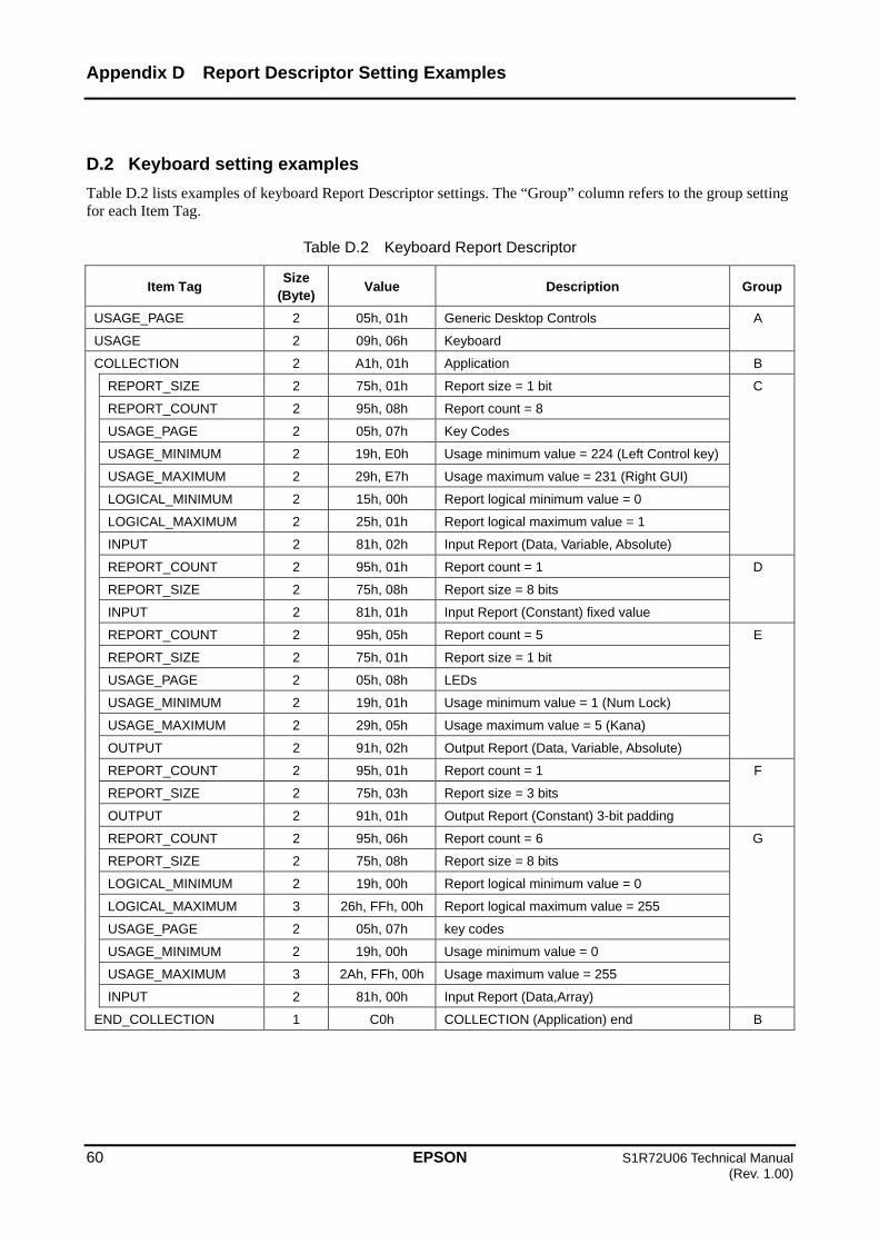
Appendix D Report Descriptor Setting Examples
60 EPSON S1R72U06 Technical Manual (Rev. 1.00)
D.2 Keyboard setting examples
Table D.2 lists examples of keyboard Report Descriptor settings. The “Group” column refers to the group setting for each Item Tag.
Table D.2 Keyboard Report Descriptor
Item Tag Size
(Byte) Value Description Group
USAGE_PAGE 2 05h, 01h Generic Desktop Controls
USAGE 2 09h, 06h Keyboard
A
COLLECTION 2 A1h, 01h Application B
REPORT_SIZE 2 75h, 01h Report size = 1 bit
REPORT_COUNT 2 95h, 08h Report count = 8
USAGE_PAGE 2 05h, 07h Key Codes
USAGE_MINIMUM 2 19h, E0h Usage minimum value = 224 (Left Control key)
USAGE_MAXIMUM 2 29h, E7h Usage maximum value = 231 (Right GUI)
LOGICAL_MINIMUM 2 15h, 00h Report logical minimum value = 0
LOGICAL_MAXIMUM 2 25h, 01h Report logical maximum value = 1
INPUT 2 81h, 02h Input Report (Data, Variable, Absolute)
C
REPORT_COUNT 2 95h, 01h Report count = 1
REPORT_SIZE 2 75h, 08h Report size = 8 bits
INPUT 2 81h, 01h Input Report (Constant) fixed value
D
REPORT_COUNT 2 95h, 05h Report count = 5
REPORT_SIZE 2 75h, 01h Report size = 1 bit
USAGE_PAGE 2 05h, 08h LEDs
USAGE_MINIMUM 2 19h, 01h Usage minimum value = 1 (Num Lock)
USAGE_MAXIMUM 2 29h, 05h Usage maximum value = 5 (Kana)
OUTPUT 2 91h, 02h Output Report (Data, Variable, Absolute)
E
REPORT_COUNT 2 95h, 01h Report count = 1
REPORT_SIZE 2 75h, 03h Report size = 3 bits
OUTPUT 2 91h, 01h Output Report (Constant) 3-bit padding
F
REPORT_COUNT 2 95h, 06h Report count = 6
REPORT_SIZE 2 75h, 08h Report size = 8 bits
LOGICAL_MINIMUM 2 19h, 00h Report logical minimum value = 0
LOGICAL_MAXIMUM 3 26h, FFh, 00h Report logical maximum value = 255
USAGE_PAGE 2 05h, 07h key codes
USAGE_MINIMUM 2 19h, 00h Usage minimum value = 0
USAGE_MAXIMUM 3 2Ah, FFh, 00h Usage maximum value = 255
INPUT 2 81h, 00h Input Report (Data,Array)
G
END_COLLECTION 1 C0h COLLECTION (Application) end B
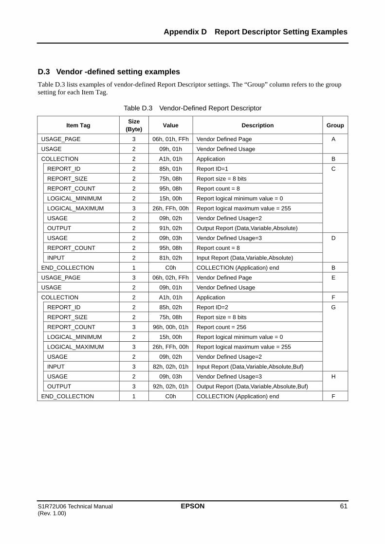
Appendix D Report Descriptor Setting Examples
S1R72U06 Technical Manual EPSON 61 (Rev. 1.00)
D.3 Vendor -defined setting examples
Table D.3 lists examples of vendor-defined Report Descriptor settings. The “Group” column refers to the group setting for each Item Tag.
Table D.3 Vendor-Defined Report Descriptor
Item Tag Size
(Byte) Value Description Group
USAGE_PAGE 3 06h, 01h, FFh Vendor Defined Page
USAGE 2 09h, 01h Vendor Defined Usage
A
COLLECTION 2 A1h, 01h Application B
REPORT_ID 2 85h, 01h Report ID=1
REPORT_SIZE 2 75h, 08h Report size = 8 bits
REPORT_COUNT 2 95h, 08h Report count = 8
LOGICAL_MINIMUM 2 15h, 00h Report logical minimum value = 0
LOGICAL_MAXIMUM 3 26h, FFh, 00h Report logical maximum value = 255
USAGE 2 09h, 02h Vendor Defined Usage=2
OUTPUT 2 91h, 02h Output Report (Data,Variable,Absolute)
C
USAGE 2 09h, 03h Vendor Defined Usage=3
REPORT_COUNT 2 95h, 08h Report count = 8
INPUT 2 81h, 02h Input Report (Data,Variable,Absolute)
D
END_COLLECTION 1 C0h COLLECTION (Application) end B
USAGE_PAGE 3 06h, 02h, FFh Vendor Defined Page
USAGE 2 09h, 01h Vendor Defined Usage
E
COLLECTION 2 A1h, 01h Application F
REPORT_ID 2 85h, 02h Report ID=2
REPORT_SIZE 2 75h, 08h Report size = 8 bits
REPORT_COUNT 3 96h, 00h, 01h Report count = 256
LOGICAL_MINIMUM 2 15h, 00h Report logical minimum value = 0
LOGICAL_MAXIMUM 3 26h, FFh, 00h Report logical maximum value = 255
USAGE 2 09h, 02h Vendor Defined Usage=2
INPUT 3 82h, 02h, 01h Input Report (Data,Variable,Absolute,Buf)
G
USAGE 2 09h, 03h Vendor Defined Usage=3
OUTPUT 3 92h, 02h, 01h Output Report (Data,Variable,Absolute,Buf)
H
END_COLLECTION 1 C0h COLLECTION (Application) end F

Appendix D Report Descriptor Setting Examples
62 EPSON S1R72U06 Technical Manual (Rev. 1.00)
D.4 Report Descriptor notes
This section provides additional information on the Report Descriptor. For detailed information, refer to the USB standard.
D.4.1 Report
(1) Reports may exist as INPUT, OUTPUT, or FEATURE Reports.
(2) Report IDs are defined only when used.
(3) Report size is specified by REPORT_COUNT and REPORT_SIZE. REPORT_SIZE is set in bits.
(4) COLLECTION and END COLLECTION group data within a Report.
(5) Report size is calculated for each Report within the range specified by COLLECTION. Using Report ID enables a different Report size to be defined even for the same type.
(6) The details included before INPUT (OUTPUT, FEATURE) are inherited. Some details such as REPORT_COUNT or REPORT_SIZE may be omitted.
D.4.2 Item Tag
(1) Report Descriptor sets the data as required after the Item Tag in “9.3.9 Report Descriptor”.
(2) The Item Tag types are listed in Table D.4. (Not a comprehensive list)
Table D.4 Item Tags
Main Item Tag Global Item Tag Local Item Tag
INPUT USAGE PAGE USAGE
OUTPUT LOGICAL MINIMUM USAGE MINIMUM
FEATURE LOGICAL MAXIMUM USAGE MAXIMUM
COLLECTION REPORT COUNT STRING INDEX
END COLLECTION REPORT SIZE STRING MINIMUM
REPORT ID STRING MAXIMUM
UNIT DELIMITER
UNIT EXPONENT
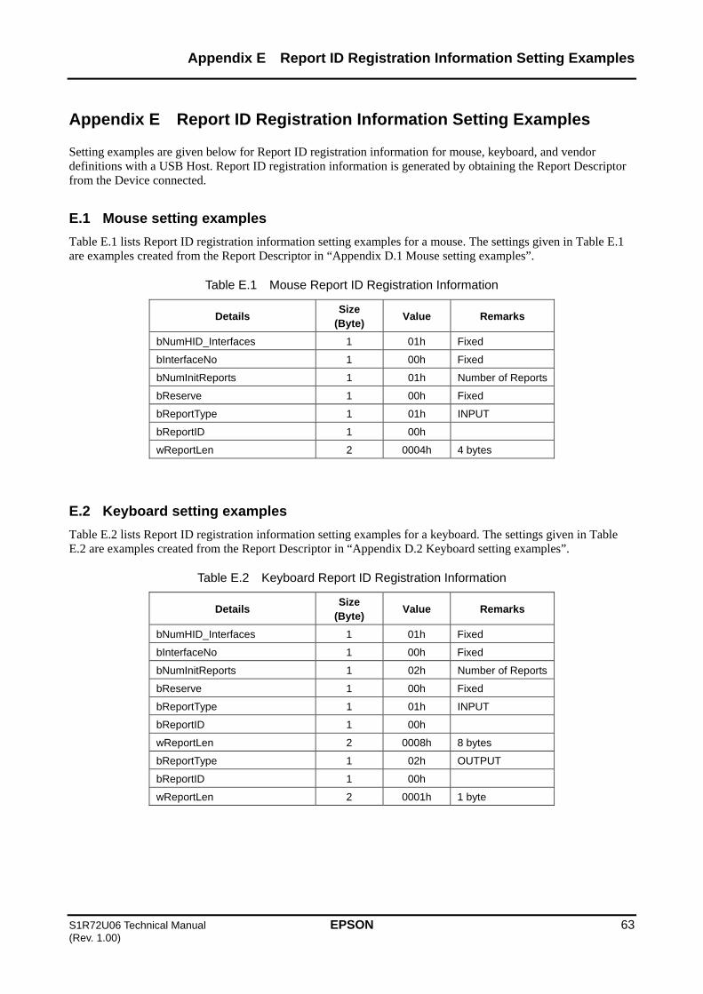
Appendix E Report ID Registration Information Setting Examples
S1R72U06 Technical Manual EPSON 63 (Rev. 1.00)
Appendix E Report ID Registration Information Setting Examples
Setting examples are given below for Report ID registration information for mouse, keyboard, and vendor definitions with a USB Host. Report ID registration information is generated by obtaining the Report Descriptor from the Device connected.
E.1 Mouse setting examples
Table E.1 lists Report ID registration information setting examples for a mouse. The settings given in Table E.1 are examples created from the Report Descriptor in “Appendix D.1 Mouse setting examples”.
Table E.1 Mouse Report ID Registration Information
Details Size
(Byte) Value Remarks
bNumHID_Interfaces 1 01h Fixed
bInterfaceNo 1 00h Fixed
bNumInitReports 1 01h Number of Reports
bReserve 1 00h Fixed
bReportType 1 01h INPUT
bReportID 1 00h
wReportLen 2 0004h 4 bytes
E.2 Keyboard setting examples
Table E.2 lists Report ID registration information setting examples for a keyboard. The settings given in Table E.2 are examples created from the Report Descriptor in “Appendix D.2 Keyboard setting examples”.
Table E.2 Keyboard Report ID Registration Information
Details Size
(Byte) Value Remarks
bNumHID_Interfaces 1 01h Fixed
bInterfaceNo 1 00h Fixed
bNumInitReports 1 02h Number of Reports
bReserve 1 00h Fixed
bReportType 1 01h INPUT
bReportID 1 00h
wReportLen 2 0008h 8 bytes
bReportType 1 02h OUTPUT
bReportID 1 00h
wReportLen 2 0001h 1 byte

Appendix E Report ID Registration Information Setting Examples
64 EPSON S1R72U06 Technical Manual (Rev. 1.00)
E.3 Vendor-defined setting examples
Table E.3 lists vendor-defined Report ID registration information setting examples. The settings given in Table E.3 are examples created from the Report Descriptor in Appendix D.3 “Vendor-defined setting examples”.
Table E.3 Vendor-Defined Report ID Registration Information
Details Size
(Byte) Value Remarks
bNumHID_Interfaces 1 01h Fixed
bInterfaceNo 1 00h Fixed
bNumInitReports 1 04h Number of Reports
bReserve 1 00h Fixed
bReportType 1 02h OUTPUT
bReportID 1 01h
wReportLen 2 0009h 9 bytes
bReportType 1 01h INPUT
bReportID 1 01h
wReportLen 2 0009h 9 bytes
bReportType 1 01h INPUT
bReportID 1 02h
wReportLen 2 0101h 257 bytes
bReportType 1 02h OUTPUT
bReportID 1 02h
wReportLen 2 0101h 257 bytes

Revision History
S1R72U06 Technical Manual EPSON 65 (Rev. 1.00)
Revision History
Attachment-1 Rev. No. Date Page Category Revision details and reason Rev. 1.00 4/6/2009 All New Newly established

International Sales Operations
AMERICA
EPSON ELECTRONICS AMERICA, INC. 2580 Orchard Parkway,
San Jose, CA 95131, USA
Phone: +1-800-228-3964 FAX: +1-408-922-0238
EUROPE
EPSON EUROPE ELECTRONICS GmbH Riesstrasse 15, 80992 Munich,
GERMANY
Phone: +49-89-14005-0 FAX: +49-89-14005-110
ASIA
EPSON (CHINA) CO., LTD. 7F, Jinbao Bldg., No.89 Jinbao St., Dongcheng District, Beijing 100005, CHINA Phone: +86-10-6410-6655 FAX: +86-10-6410-7320
SHANGHAI BRANCH 7F, Block B, Hi-Tech Bldg., 900 Yishan Road, Shanghai 200233, CHINA Phone: +86-21-5423-5522 FAX: +86-21-5423-5512
SHENZHEN BRANCH 12F, Dawning Mansion, Keji South 12th Road, Hi-Tech Park, Shenzhen 518057, CHINA Phone: +86-755-2699-3828 FAX: +86-755-2699-3838 EPSON HONG KONG LTD. 20/F, Harbour Centre, 25 Harbour Road, Wanchai, Hong Kong Phone: +852-2585-4600 FAX: +852-2827-4346 Telex: 65542 EPSCO HX EPSON TAIWAN TECHNOLOGY & TRADING LTD. 14F, No. 7, Song Ren Road, Taipei 110, TAIWAN Phone: +886-2-8786-6688 FAX: +886-2-8786-6660 EPSON SINGAPORE PTE., LTD. 1 HarbourFront Place,
#03-02 HarbourFront Tower One, Singapore 098633 Phone: +65-6586-5500 FAX: +65-6271-3182 SEIKO EPSON CORP. KOREA OFFICE 50F, KLI 63 Bldg., 60 Yoido-dong, Youngdeungpo-Ku, Seoul 150-763, KOREA Phone: +82-2-784-6027 FAX: +82-2-767-3677
SEIKO EPSON CORP. SEMICONDUCTOR OPERATIONS DIVISION IC Sales Dept. IC International Sales Group 421-8, Hino, Hino-shi, Tokyo 191-8501, JAPAN Phone: +81-42-587-5814 FAX: +81-42-587-5117
Document Code: 411665101 First Issue April 2009 in JAPAN D