s1' series stainless steel shaft drive propellers installation
TRANSCRIPT
‘S1’ Series Stainless Steel Shaft Drive Propellers
INSTALLATION AND OPERATING INSTRUCTIONS

Index
Index . . . . . . . . . . . . . . . . . . . . . . . . . . . . . . . . . . . . . . . . . . . . . . . . . . . . .1Foreword . . . . . . . . . . . . . . . . . . . . . . . . . . . . . . . . . . . . . . . . . . . . . . . . . .1Getting to Know Your Propeller Parts . . . . . . . . . . . . . . . . . . . . . . . . . . . .2Pre-installation check . . . . . . . . . . . . . . . . . . . . . . . . . . . . . . . . . . . . . . . .3Fitting your AUTOSTREAM propeller . . . . . . . . . . . . . . . . . . . . . . . . . . . .4Anti fouling the propeller . . . . . . . . . . . . . . . . . . . . . . . . . . . . . . . . . . . . . .7Operating instructions . . . . . . . . . . . . . . . . . . . . . . . . . . . . . . . . . . . . . . . .8Sea Trials & Pitch Adjustment . . . . . . . . . . . . . . . . . . . . . . . . . . . . . . . . . .8Shaft Generators and Electric Motor Regeneration . . . . . . . . . . . . . . . .10Recommended Greases . . . . . . . . . . . . . . . . . . . . . . . . . . . . . . . . . . . . .10Recommended Propeller Nut Torque Wrench Settings . . . . . . . . . . . . . .10Machining the Taper . . . . . . . . . . . . . . . . . . . . . . . . . . . . . . . . . . . . . . . .10Removal of Propeller . . . . . . . . . . . . . . . . . . . . . . . . . . . . . . . . . . . . . . . . 11Servicing . . . . . . . . . . . . . . . . . . . . . . . . . . . . . . . . . . . . . . . . . . . . . . . . . 11Replacing the Zinc Anode . . . . . . . . . . . . . . . . . . . . . . . . . . . . . . . . . . . .12Replacing the Blade Bearings and/or O-ring Seals . . . . . . . . . . . . . . . .12Contact Details . . . . . . . . . . . . . . . . . . . . . . . . . . . . . . Inside Back Cover
Foreword
At first glance it may appear that installation is complex, this is not the case . These instructions are very detailed to assist a person without any trade skills to successfully fit & adjust our propellers .
Please read and follow these instructions carefully, Failure to do so may result in unsatisfactory performance, vibration, additional slipping/ haul out costs, loss of propeller or voiding your 5 year warranty .
Our experience has shown most problems stem from not following these instructions . Avoid potential frustration and read on . . .
1
2
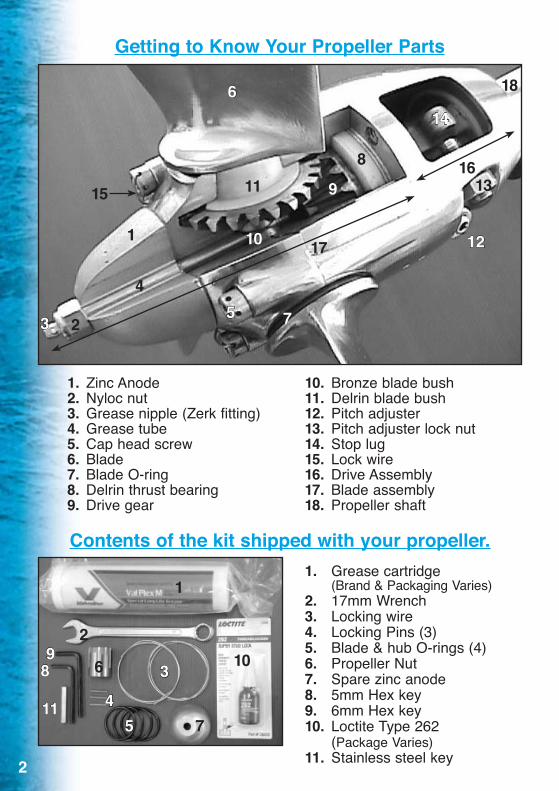
Getting to Know Your Propeller Parts
1. Zinc Anode 10. Bronze blade bush2. Nyloc nut 11. Delrin blade bush3. Grease nipple (Zerk fitting) 12. Pitch adjuster4. Grease tube 13. Pitch adjuster lock nut5. Cap head screw 14. Stop lug6. Blade 15. Lock wire7. Blade O-ring 16. Drive Assembly8. Delrin thrust bearing 17. Blade assembly9. Drive gear 18. Propeller shaft
Contents of the kit shipped with your propeller. 1. Grease cartridge (Brand & Packaging Varies) 2. 17mm Wrench 3. Locking wire 4. Locking Pins (3) 5. Blade & hub O-rings (4) 6. Propeller Nut 7. Spare zinc anode 8. 5mm Hex key 9. 6mm Hex key 10. Loctite Type 262 (Package Varies) 11. Stainless steel key
12
14
1316
17
75
10
4
1
1115
6
9
8
18
23
1
2
3
45
6
7
10
11
89
3
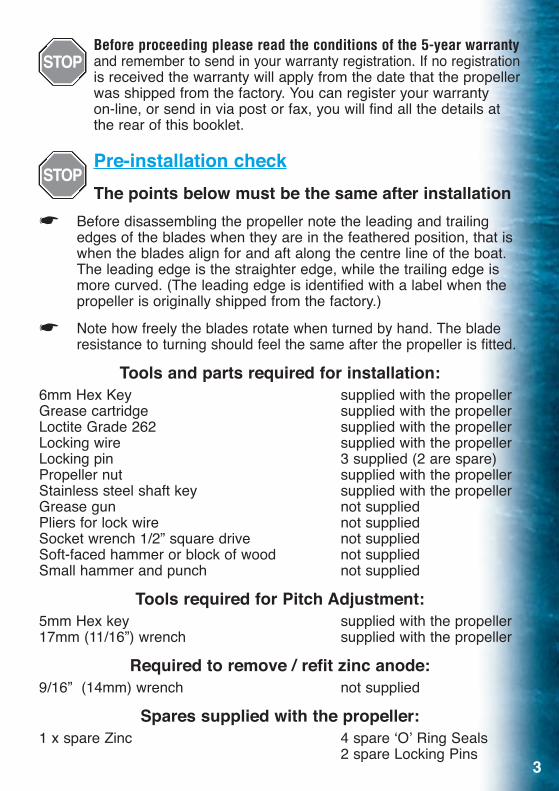
Before proceeding please read the conditions of the 5-year warranty and remember to send in your warranty registration . If no registration is received the warranty will apply from the date that the propeller was shipped from the factory . You can register your warranty on-line, or send in via post or fax, you will find all the details at the rear of this booklet .
Pre-installation checkThe points below must be the same after installation
☛ Before disassembling the propeller note the leading and trailing edges of the blades when they are in the feathered position, that is when the blades align for and aft along the centre line of the boat . The leading edge is the straighter edge, while the trailing edge is more curved . (The leading edge is identified with a label when the propeller is originally shipped from the factory .)
☛ Note how freely the blades rotate when turned by hand . The blade resistance to turning should feel the same after the propeller is fitted .
Tools and parts required for installation:6mm Hex Key supplied with the propellerGrease cartridge supplied with the propellerLoctite Grade 262 supplied with the propellerLocking wire supplied with the propellerLocking pin 3 supplied (2 are spare)Propeller nut supplied with the propellerStainless steel shaft key supplied with the propellerGrease gun not suppliedPliers for lock wire not suppliedSocket wrench 1/2” square drive not suppliedSoft-faced hammer or block of wood not suppliedSmall hammer and punch not supplied
Tools required for Pitch Adjustment:5mm Hex key supplied with the propeller17mm (11/16”) wrench supplied with the propeller
Required to remove / refit zinc anode:9/16” (14mm) wrench not supplied
Spares supplied with the propeller:1 x spare Zinc 4 spare ‘O’ Ring Seals 2 spare Locking Pins
4
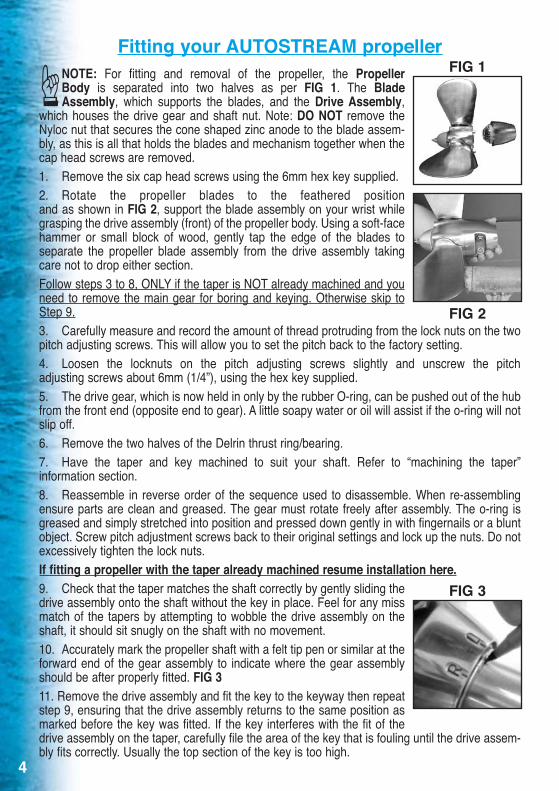
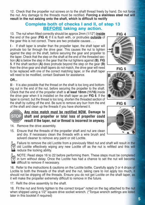
Fitting your AUTOSTREAM propeller NOTE: For fitting and removal of the propeller, the Propeller Body is separated into two halves as per FIG 1 . The Blade Assembly, which supports the blades, and the Drive Assembly, which houses the drive gear and shaft nut . Note: DO NOT remove the Nyloc nut that secures the cone shaped zinc anode to the blade assem-bly, as this is all that holds the blades and mechanism together when the cap head screws are removed .1 . Remove the six cap head screws using the 6mm hex key supplied .2 . Rotate the propeller blades to the feathered position and as shown in FIG 2, support the blade assembly on your wrist while grasping the drive assembly (front) of the propeller body . Using a soft-face hammer or small block of wood, gently tap the edge of the blades to separate the propeller blade assembly from the drive assembly taking care not to drop either section .Follow steps 3 to 8, ONLY if the taper is NOT already machined and you need to remove the main gear for boring and keying . Otherwise skip to Step 9 .3 . Carefully measure and record the amount of thread protruding from the lock nuts on the two pitch adjusting screws . This will allow you to set the pitch back to the factory setting .4 . Loosen the locknuts on the pitch adjusting screws slightly and unscrew the pitch adjusting screws about 6mm (1/4”), using the hex key supplied .5 . The drive gear, which is now held in only by the rubber O-ring, can be pushed out of the hub from the front end (opposite end to gear) . A little soapy water or oil will assist if the o-ring will not slip off .6 . Remove the two halves of the Delrin thrust ring/bearing .7 . Have the taper and key machined to suit your shaft . Refer to “machining the taper” information section .8 . Reassemble in reverse order of the sequence used to disassemble . When re-assembling ensure parts are clean and greased . The gear must rotate freely after assembly . The o-ring is greased and simply stretched into position and pressed down gently in with fingernails or a blunt object . Screw pitch adjustment screws back to their original settings and lock up the nuts . Do not excessively tighten the lock nuts .If fitting a propeller with the taper already machined resume installation here.9 . Check that the taper matches the shaft correctly by gently sliding the drive assembly onto the shaft without the key in place . Feel for any miss match of the tapers by attempting to wobble the drive assembly on the shaft, it should sit snugly on the shaft with no movement .10 . Accurately mark the propeller shaft with a felt tip pen or similar at the forward end of the gear assembly to indicate where the gear assembly should be after properly fitted . FIG 311 . Remove the drive assembly and fit the key to the keyway then repeat step 9, ensuring that the drive assembly returns to the same position as marked before the key was fitted . If the key interferes with the fit of the drive assembly on the taper, carefully file the area of the key that is fouling until the drive assem-bly fits correctly . Usually the top section of the key is too high .
FIG 1☞
FIG 2
FIG 3
5
12 . Check that the propeller nut screws on to the shaft thread freely by hand . Do not force the nut . Any damage to the threads must be rectified . Forcing a stainless steel nut will result in the nut seizing onto the shaft, which is difficult to rectify
Complete both of checks I and II, of step 13 BEFORE taking any action.
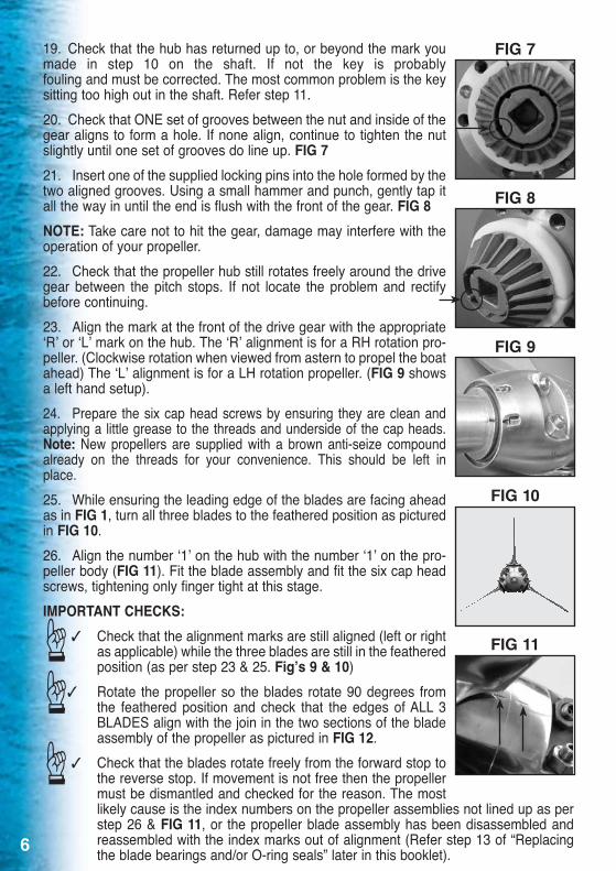
13 . The nut when fitted correctly should be approx 2mm (1/12”) inside the end of the gear (FIG 4) If it is flush with, or protrudes outside of the gear this is not correct . There are two probable causes . . .I - If shaft taper is smaller than the propeller taper, the shaft taper will protrude too far through the drive gear . This causes the nut to tighten against the step on the shaft, before securing the gear and propeller to the taper . Check that the step on the shaft at the end of the threaded sec-tion (A) is below the step in the gear that the nut tightens against (B) . FIG 5 . If the shaft section (A) does protrude beyond the step on the gear (B) then the drive gear and shaft tapers do not match, the drive gear will need to be replaced with one of the correct matching taper, or the shaft taper will need to be modified, contact Seahawk for assistance .OR...II - It is also possible that the thread on the shaft is too long and bottom-ing out in the end of the nut, before securing the propeller to the shaft . Check that the end of the propeller shaft is at least 18mm (11/16) inside the drive gear when it is installed on the shaft taper as per FIG 6 . If the taper is correct, but the thread is too long, shorten the threaded section of the shaft by cutting off the end . Be sure to remove any burr from the end of the shaft and clean up the threads if you have shortened it .
Any miss match must be rectified NOW. Damage to shaft and propeller or total loss of propeller could result if the taper, nut or thread is incorrect in anyway.
14 . Remove the drive assembly .15 . Ensure that the threads of the propeller shaft and nut are clean and dry . If necessary clean the threads with a wire brush and solvent cleaner to remove any paint or old Loctite .
Failure to remove the old Loctite from a previously fitted nut and shaft will result in the old Loctite effectively wiping any new Loctite off as the nut is refitted and this will reduce the locking ability .NOTE: Read steps 16 to 22 before performing them . These steps must be completed in turn without delay . Once the Loctite has had a chance to set the nut will become difficult to remove if necessary .
16 . Refer to the instructions & cautions on the Loctite bottle . Carefully apply 3 or 4 drops of Loctite to both the threads of the shaft and the nut, taking care to not apply too much, it should not be dripping off the threads . Ensure you do not get Loctite on the shaft taper, as it will make the propeller extremely difficult to remove in the future .17 . Refit the drive assembly to the shaft .18 . Fit the nut and firmly tighten to the correct torque* noted on the tag attached to the nut when shipped using a 1/2” square drive socket wrench . (*Torque wrench settings are listed later in this booklet if required)
FIG 4
FIG 5
FIG 6
B A
☞☞
6
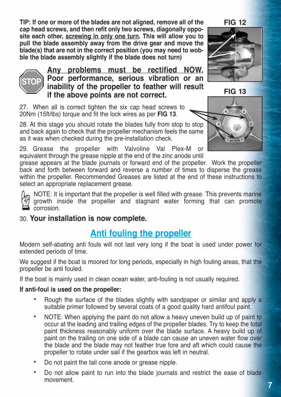
19 . Check that the hub has returned up to, or beyond the mark you made in step 10 on the shaft . If not the key is probably fouling and must be corrected . The most common problem is the key sitting too high out in the shaft . Refer step 11 . 20 . Check that ONE set of grooves between the nut and inside of the gear aligns to form a hole . If none align, continue to tighten the nut slightly until one set of grooves do line up . FIG 721 . Insert one of the supplied locking pins into the hole formed by the two aligned grooves . Using a small hammer and punch, gently tap it all the way in until the end is flush with the front of the gear . FIG 8NOTE: Take care not to hit the gear, damage may interfere with the operation of your propeller . 22 . Check that the propeller hub still rotates freely around the drive gear between the pitch stops . If not locate the problem and rectify before continuing . 23 . Align the mark at the front of the drive gear with the appropriate ‘R’ or ‘L’ mark on the hub . The ‘R’ alignment is for a RH rotation pro-peller . (Clockwise rotation when viewed from astern to propel the boat ahead) The ‘L’ alignment is for a LH rotation propeller . (FIG 9 shows a left hand setup) .24 . Prepare the six cap head screws by ensuring they are clean and applying a little grease to the threads and underside of the cap heads . Note: New propellers are supplied with a brown anti-seize compound already on the threads for your convenience . This should be left in place .25 . While ensuring the leading edge of the blades are facing ahead as in FIG 1, turn all three blades to the feathered position as pictured in FIG 10 .26 . Align the number ‘1’ on the hub with the number ‘1’ on the pro-peller body (FIG 11) . Fit the blade assembly and fit the six cap head screws, tightening only finger tight at this stage .IMPORTANT CHECKS: ✓ Check that the alignment marks are still aligned (left or right
as applicable) while the three blades are still in the feathered position (as per step 23 & 25 . Fig’s 9 & 10)
✓ Rotate the propeller so the blades rotate 90 degrees from the feathered position and check that the edges of ALL 3 BLADES align with the join in the two sections of the blade assembly of the propeller as pictured in FIG 12 .
✓ Check that the blades rotate freely from the forward stop to the reverse stop . If movement is not free then the propeller must be dismantled and checked for the reason . The most likely cause is the index numbers on the propeller assemblies not lined up as per step 26 & FIG 11, or the propeller blade assembly has been disassembled and reassembled with the index marks out of alignment (Refer step 13 of “Replacing the blade bearings and/or O-ring seals” later in this booklet) .
FIG 7
FIG 8
FIG 9
FIG 10
FIG 11☞☞
☞
7
TIP: If one or more of the blades are not aligned, remove all of the cap head screws, and then refit only two screws, diagonally oppo-site each other, screwing in only one turn. This will allow you to pull the blade assembly away from the drive gear and move the blade(s) that are not in the correct position (you may need to wob-ble the blade assembly slightly if the blade does not turn)
Any problems must be rectified NOW. Poor performance, serious vibration or an inability of the propeller to feather will result if the above points are not correct.
27 . When all is correct tighten the six cap head screws to 20Nm 20Nm (15ft/lbs) torque and fit the lock wires as per FIG 13 .28 . At this stage you should rotate the blades fully from stop to stop and back again to check that the propeller mechanism feels the same as it was when checked during the pre-installation check .29 . Grease the propeller with Valvoline Val Plex-M or equivalent through the grease nipple at the end of the zinc anode until grease appears at the blade journals or forward end of the propeller . Work the propeller back and forth between forward and reverse a number of times to disperse the grease within the propeller . Recommended Greases are listed at the end of these instructions to select an appropriate replacement grease .
NOTE: It is important that the propeller is well filled with grease . This prevents marine growth inside the propeller and stagnant water forming that can promote corrosion .
30 . Your installation is now complete.
Anti fouling the propellerModern self-abating anti fouls will not last very long if the boat is used under power for extended periods of time .We suggest if the boat is moored for long periods, especially in high fouling areas, that the propeller be anti fouled .If the boat is mainly used in clean ocean water, anti-fouling is not usually required .If anti-foul is used on the propeller: • Rough the surface of the blades slightly with sandpaper or similar and apply a
suitable primer followed by several coats of a good quality hard antifoul paint . • NOTE: When applying the paint do not allow a heavy uneven build up of paint to
occur at the leading and trailing edges of the propeller blades . Try to keep the total paint thickness reasonably uniform over the blade surface . A heavy build up of paint on the trailing on one side of a blade can cause an uneven water flow over the blade and the blade may not feather true fore and aft which could cause the propeller to rotate under sail if the gearbox was left in neutral .
• Do not paint the tail cone anode or grease nipple . • Do not allow paint to run into the blade journals and restrict the ease of blade
movement .
☞
FIG 13
FIG 12
8
Operating instructionsOperation under engine power:Operate your sailboat under power as though it has a fixed blade propeller .The propeller blades will orientate automatically when the engine is engaged in either forward or reverse .The propeller will go into reverse at high speed if required for emergency stopping . It will not damage the propeller but continued high-speed direction changes will accelerate the wear on both the propeller and your drive train .CAUTION: Autostream propellers are much more efficient in reverse than other types of propellers, take care reversing in confined areas as you may be doing 3 to 4 times the speed for the same rpm that you were with your old propeller .Feathering the propeller: To feather the propeller, drive ahead at a speed slightly greater than the speed the boat is currently sailing at, this will ensure the propeller is in the ahead position so it will feather correctly .Switch off the engine whilst still engaged in forward gear .After the engine has stopped, momentarily engage reverse gear - this will prevent the propeller shaft rotating and the propeller will feather .To check if the propeller is feathered, put the gear lever in neutral, the propeller shaft should not rotate .If it does then the propeller is not feathered and the procedure should be repeated .Once feathered the gear lever can be left in any position and the propeller will not come out of the feathered position until the propeller shaft is rotated by the engine .This procedure is affective for both hydraulic and mechanical transmissions.NOTE: When first filled with grease the movement of the propeller blades will be a little stiff until the grease is dispersed inside the propeller body . Until this happens the time it takes for the propeller to feather may be a little longer .Going from forward to reverse at idle about 10 times will help disperse the grease quicker .NOTE: The propeller will only feather from the ahead position.Note for high speed use: Autostream propellers have been regularly tested at speeds over 25 knots and have been proven to stay feathered under normal conditions. It is highly recommended when sailing at high speeds that the gearbox is left in neutral. This will prevent potential engine damage should the propeller be forced out of the feathered position by a foreign object in the water.
Sea Trials & Pitch AdjustmentThe propeller pitch is generally preset using the information supplied when your propeller was ordered . However, fine-tuning will achieve optimum performance .The pitch is correct when the engine just reaches the engine manufacturers maximum continuous rated rpm, under flat-water conditions .Over revving is not enough pitch, while black smoke or ‘lugging’ is too much pitch .Half a turn of the pitch adjusting screw will make about 150 rpm alteration on most installations .
9
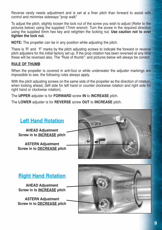
Reverse rarely needs adjustment and is set at a finer pitch than forward to assist with control and minimise sideways “prop walk”To adjust the pitch, slightly loosen the lock nut of the screw you wish to adjust (Refer to the pictures below) using the supplied 17mm wrench . Turn the screw in the required direction using the supplied 5mm hex key and retighten the locking nut . Use caution not to over tighten the lock nut.NOTE: The propeller can be in any position while adjusting the pitch .There is ‘R’ and ‘F’ marks by the pitch adjusting screws to indicate the forward or reverse pitch adjusters for the initial factory set up . If the prop rotation has been reversed at any time these will be reversed also . The “Rule of thumb”: and pictures below will always be correct .RULE OF THUMBWhen the propeller is covered in anti-foul or while underwater the adjuster markings are impossible to see, the following rules always apply .With the pitch adjusting screws on the same side of the propeller as the direction of rotation, when looking ahead, (left side for left hand or counter clockwise rotation and right side for right hand or clockwise rotation) . The UPPER adjuster is for FORWARD screw IN to INCREASE pitch .The LOWER adjuster is for REVERSE screw OUT to INCREASE pitch .
Left Hand RotationAHEAD Adjustment
Screw in to INCREASE pitch
ASTERN Adjustment Screw in to DECREASE pitch
Right Hand RotationAHEAD Adjustment
Screw in to INCREASE pitch
ASTERN Adjustment Screw in to DECREASE pitch
10
Shaft Generators and Electric Motor Regeneration:As the propeller will not feather from the reverse position, this feature can be utilized to drive the shaft for power generation .To engage the propeller, start the engine and briefly reverse as you begin to sail off, then select neutral and shut down the engine . The propeller blades will now stay in the reverse position and rotate the shaft . To feather the propeller when required simply follow the normal procedure for feathering as described previously .
Recommended GreasesAny light multi-purpose, lithium based grease, particularly if labelled as suitable for marine use, is suitable for use in your AUTOSTREAM Propeller . Extreme pressure grease can be used but is not required .A few alternatives are . . .Valvoline Val Plex M grease, Mobil Mobilgrease XHP, Castrol LMX,Spheerol AP or LMM, Total Lubmarine EPEXZ .
NOTE: It is important that the propeller is well filled with grease . This prevents marine growth forming inside the propeller and stagnant water forming that can promote corrosion .
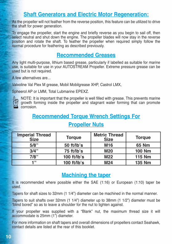
Recommended Torque Wrench Settings ForPropeller Nuts
Machining the taperIt is recommended where possible either the SAE (1:16) or European (1:10) taper be used . Tapers for shaft sizes to 32mm (1 1/4”) diameter can be machined in the normal manner .Tapers to suit shafts over 32mm (1 1/4”) diameter up to 38mm (1 1/2”) diameter must be “blind bored” so as to leave a shoulder for the nut to tighten against .If your propeller was supplied with a “Blank” nut, the maximum thread size it will accommodate is 25mm (1”) diameter .For more information on shaft tapers and overall dimensions of propellers contact Seahawk, contact details are listed at the rear of this booklet .
Imperial ThreadSize5/8”3/4”7/8”1”
Metric ThreadSizeM16M20M22M24
Torque50 ft/lb’s75 ft/lb’s100 ft/lb’s100 ft/lb’s
Torque65 Nm100 Nm115 Nm135 Nm
☞
11
Removal of PropellerRemoval of the propeller is basically the reverse of installation . 1 . Turn the propeller blades to the feathered position . 2 . Cut the locking wire and remove from the six cap head screws . 3 . Using a soft face hammer or small block of wood knock the blades gently to remove
the blade assembly, taking care not to drop it . 4 . Firmly secure the propeller shaft . 5 . Using a 1/2” drive socket wrench apply firm pressure to undo the propeller nut . You will
need to overcome the locking ability of the Loctite and shear the locking pin (brass tube) . Once the pin shears and the Loctite “lets go” the nut can be unscrewed normally . USE CARE - THE SHARDS OF THE SHEARED PIN ARE VERY SHARP
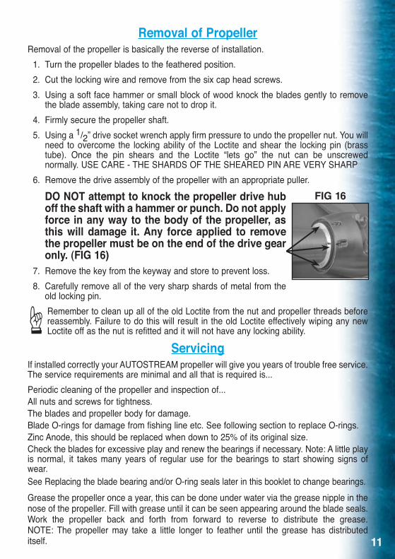
6 . Remove the drive assembly of the propeller with an appropriate puller .
DO NOT attempt to knock the propeller drive hub off the shaft with a hammer or punch. Do not apply force in any way to the body of the propeller, as this will damage it. Any force applied to remove the propeller must be on the end of the drive gear only. (FIG 16)
7 . Remove the key from the keyway and store to prevent loss . 8 . Carefully remove all of the very sharp shards of metal from the
old locking pin . Remember to clean up all of the old Loctite from the nut and propeller threads before reassembly . Failure to do this will result in the old Loctite effectively wiping any new Loctite off as the nut is refitted and it will not have any locking ability .
ServicingIf installed correctly your AUTOSTREAM propeller will give you years of trouble free service . The service requirements are minimal and all that is required is . . .Periodic cleaning of the propeller and inspection of . . .All nuts and screws for tightness .The blades and propeller body for damage .Blade O-rings for damage from fishing line etc . See following section to replace O-rings .Zinc Anode, this should be replaced when down to 25% of its original size .Check the blades for excessive play and renew the bearings if necessary . Note: A little play is normal, it takes many years of regular use for the bearings to start showing signs of wear . See Replacing the blade bearing and/or O-ring seals later in this booklet to change bearings .Grease the propeller once a year, this can be done under water via the grease nipple in the nose of the propeller . Fill with grease until it can be seen appearing around the blade seals . Work the propeller back and forth from forward to reverse to distribute the grease . NOTE: The propeller may take a little longer to feather until the grease has distributed itself .
FIG 16
☞
12
Replacing the Zinc AnodeThe zinc anode should be replaced when eroded down to approximately 25% of its original size, this can be done while still in the water . In normal use the zinc anode should last between 6 & 18 months . If your zinc anode is lasting less than six months have your boat checked for an electrical leakage problem .Undo the 14mm (9/16”) Nyloc nut at the grease nipple and slide the anode off .Clean the area where the zinc anode is mounted with sandpaper or a wire brush .Fit the new zinc anode and tighten the Nyloc nut 14mm (9/16”) wrench required .NOTE: We recommend that you still use a shaft anode to protect the shaft and the propeller hub .
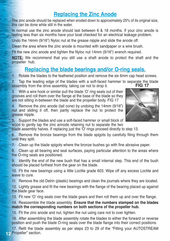
Replacing the blade bearings and/or O-ring seals.1 . Rotate the blades to the feathered position and remove the six 6mm cap head screws .2 . Tap the leading edge of the blades with a soft-faced hammer to separate the blade assembly from the drive assembly, taking car not to drop it .3 . With a wire hook or similar pull the blade ‘O’ ring seals out of their grooves and roll them over the flange at the base of the blade so they are not sitting in-between the blade and the propeller body . FIG 174 . Remove the zinc anode (tail cone) by undoing the 14mm (9/16”) nut and sliding it off, then partly replace the nut to protect the grease nipple .5 . Support the blades and use a soft-faced hammer or small block of wood to gently tap the zinc annode retaining nut to separate the two blade assembly halves . If replacing just the 'O' rings proceed directly to step 13 .6 . Remove the bronze bearings from the blade spigots by carefully filing through them until they split .7 . Clean up the blade spigots where the bronze bushes go with fine abrasive paper .8 . Clean up all bearing and seal surfaces, paying particular attention to the areas where the O-ring seals are positioned .9 . Identify the end of the new bush that has a small internal step . This end of the bush should be placed furthest from the gear on the blade .10 . Fit the new bearings using a little Loctite grade 603 . Wipe off any excess Loctite and leave to cure .11 . Remove the old Delrin (plastic) bearings and clean the journals where they are located .12 . Lightly grease and fit the new bearings with the flange of the bearing placed up against the blade gear face .13 . Fit new ‘O’ ring seals over the blade gears and then roll them up and over the flange .14 . Reassemble the blade assembly . Ensure that the numbers stamped on the blades match the corresponding numbers on both sections of the propeller hub.15 . Fit the zinc anode and nut, tighten the nut using care not to over tighten .16 . After assembling the blade assembly rotate the blades to either the forward or reverse position and push the blade O-ring seals over the blade flange into their correct positions .17 . Refit the blade assembly as per steps 23 to 29 of the “Fitting your AUTOSTREAM Propeller” section .
FIG 17

Notes and Important DataPropeller serial number . . . . . . . . . . . . . . . . . . . . . . . . . . . . . . . . . Nut size & thread . . . . . . . . . . . . . . . . . . . . . . . . . . . . . . . . . . . . . . . . . . . .
Shaft Size & Taper . . . . . . . . . . . . . . . . . . . . . . . . . . . . . . . . . . . . . . . . Purchase Date . . . . . . . . . . . . . . . . . . . . . . . . . . . . . . . . . . . . . . . . . . . . . . .
Purchased from . . . . . . . . . . . . . . . . . . . . . . . . . . . . . . . . . . . . . . . . . . . . . . . . . . . . . . . . . . . . . . . . . . . . . . . . . . . . . . . . . . . . . . . . . . . . . . . . . . . . . . . . . . . . . . . . . . . . . .
Notes: . . . . . . . . . . . . . . . . . . . . . . . . . . . . . . . . . . . . . . . . . . . . . . . . . . . . . . . . . . . . . . . . . . . . . . . . . . . . . . . . . . . . . . . . . . . . . . . . . . . . . . . . . . . . . . . . . . . . . . . . . . . . . . . . . . . . .
. . . . . . . . . . . . . . . . . . . . . . . . . . . . . . . . . . . . . . . . . . . . . . . . . . . . . . . . . . . . . . . . . . . . . . . . . . . . . . . . . . . . . . . . . . . . . . . . . . . . . . . . . . . . . . . . . . . . . . . . . . . . . . . . . . . . . . . . . . . . . . . .
. . . . . . . . . . . . . . . . . . . . . . . . . . . . . . . . . . . . . . . . . . . . . . . . . . . . . . . . . . . . . . . . . . . . . . . . . . . . . . . . . . . . . . . . . . . . . . . . . . . . . . . . . . . . . . . . . . . . . . . . . . . . . . . . . . . . . . . . . . . . . . . .
. . . . . . . . . . . . . . . . . . . . . . . . . . . . . . . . . . . . . . . . . . . . . . . . . . . . . . . . . . . . . . . . . . . . . . . . . . . . . . . . . . . . . . . . . . . . . . . . . . . . . . . . . . . . . . . . . . . . . . . . . . . . . . . . . . . . . . . . . . . . . . . .
. . . . . . . . . . . . . . . . . . . . . . . . . . . . . . . . . . . . . . . . . . . . . . . . . . . . . . . . . . . . . . . . . . . . . . . . . . . . . . . . . . . . . . . . . . . . . . . . . . . . . . . . . . . . . . . . . . . . . . . . . . . . . . . . . . . . . . . . . . . . . . . .
. . . . . . . . . . . . . . . . . . . . . . . . . . . . . . . . . . . . . . . . . . . . . . . . . . . . . . . . . . . . . . . . . . . . . . . . . . . . . . . . . . . . . . . . . . . . . . . . . . . . . . . . . . . . . . . . . . . . . . . . . . . . . . . . . . . . . . . . . . . . . . . .
. . . . . . . . . . . . . . . . . . . . . . . . . . . . . . . . . . . . . . . . . . . . . . . . . . . . . . . . . . . . . . . . . . . . . . . . . . . . . . . . . . . . . . . . . . . . . . . . . . . . . . . . . . . . . . . . . . . . . . . . . . . . . . . . . . . . . . . . . . . . . . . .
. . . . . . . . . . . . . . . . . . . . . . . . . . . . . . . . . . . . . . . . . . . . . . . . . . . . . . . . . . . . . . . . . . . . . . . . . . . . . . . . . . . . . . . . . . . . . . . . . . . . . . . . . . . . . . . . . . . . . . . . . . . . . . . . . . . . . . . . . . . . . . . .
. . . . . . . . . . . . . . . . . . . . . . . . . . . . . . . . . . . . . . . . . . . . . . . . . . . . . . . . . . . . . . . . . . . . . . . . . . . . . . . . . . . . . . . . . . . . . . . . . . . . . . . . . . . . . . . . . . . . . . . . . . . . . . . . . . . . . . . . . . . . . . . .
. . . . . . . . . . . . . . . . . . . . . . . . . . . . . . . . . . . . . . . . . . . . . . . . . . . . . . . . . . . . . . . . . . . . . . . . . . . . . . . . . . . . . . . . . . . . . . . . . . . . . . . . . . . . . . . . . . . . . . . . . . . . . . . . . . . . . . . . . . . . . . . .
. . . . . . . . . . . . . . . . . . . . . . . . . . . . . . . . . . . . . . . . . . . . . . . . . . . . . . . . . . . . . . . . . . . . . . . . . . . . . . . . . . . . . . . . . . . . . . . . . . . . . . . . . . . . . . . . . . . . . . . . . . . . . . . . . . . . . . . . . . . . . . . .
Contact Details
The team at SEAHAWK would like to thank you for purchasing your AUTOSTREAM propeller and wish you many years of happy and trouble free sailing .
If we can help you in anyway, if you would like some clarification on these instructions or if you would like some advice, please do not hesitate to contact us . We also invite you to comment on your experiences with your AUTOSTREAM propeller once you have spent some time using it .
Seahawk Pty Ltd www .seahawk .com .au 41 London Drive, info@seahawk .com .au Bayswater, Vic, 3153 Phone +61 (3) 9761 1633 AUSTRALIA Fax +61 (3) 9761 0727