s u p e r c h a r g e r s - paxton auto ford 4.6l mustang gt (3-valve) charge cooler upgrade ... d....
TRANSCRIPT

DP/N: 4809656 - v1.0 09/13/05
S U P E R C H A R G E R S
Owner’s Installation Guide for the
Paxton Automotive2005 Ford 4.6L Mustang GT (3-Valve)
Charge Cooler UpgradeP/N: 1300005
Paxton Automotive . 1300 Beacon Place . Oxnard CA 93033805 604-1336 . FAX • 805 604-1337

P/N: 4809656© 2005 Paxton AutomotiveAll Rights Reserved, Intl. Copr. Secured.13SEP05v1.0(4809656v1.0)ChrgClrUpgrd ii
FOREWORD
Proper installation of this supercharger kit requires generalautomotive mechanic knowledge and experience. Pleasebrowse through each step of this instruction manual prior to
beginning the installation to determine if you should refer the jobto a professional installer/technician. Please call PaxtonAutomotive for installers in your area.
© 2005 PAXTON AUTOMOTIVEAll rights reserved. No part of this publication may be reproduced, transmitted, transcribed,or translated into another language in any form, by any means without written permission
of PAXTON AUTOMOTIVE.

P/N: 4809656© 2005 Paxton Automotive
All Rights Reserved, Intl. Copr. Secured.13SEP05v1.0(4809656v1.0)ChrgClrUpgrdiii
TABLE OF CONTENTS
FOREWORD . . . . . . . . . . . . . . . . . . . . . . . . . . . . . . . . . . . . . . . . . . . . . . . . . . . . . . . . . . .ii
TABLE OF CONTENTS . . . . . . . . . . . . . . . . . . . . . . . . . . . . . . . . . . . . . . . . . . . . . . . . .iii
NOTICES . . . . . . . . . . . . . . . . . . . . . . . . . . . . . . . . . . . . . . . . . . . . . . . . . . . . . . . . . . . . .iv
TOOL & SUPPLY REQUIREMENTS . . . . . . . . . . . . . . . . . . . . . . . . . . . . . . . . . . . . . .v
PARTS LIST (2005 Mustang GT, Charge cooler upgrade) . . . . . . . . . . . . . . . . . . . . . . . .vi
1. PREPARATION AND REMOVAL . . . . . . . . . . . . . . . . . . . . . . . . . . . . . . . . . . . . . . .1-1
2. SUPERCHARGER RECLOCKING AND REINSTALLATION . . . . . . . . . . . . . . . . .2-1
3. CHARGE AIR COOLER INSTALLATION . . . . . . . . . . . . . . . . . . . . . . . . . . . . . . .3-1
A. BUMPER COVER AND SPLASH PAN . . . . . . . . . . . . . . . . . . . . . . . . . . . . .3-1
B. CHARGE AIR COOLER ASSEMBLY . . . . . . . . . . . . . . . . . . . . . . . . . . . . . . .3-4
C. COMPRESSOR BYPASS VALVE ASSEMBLY INSTALLATION . . . . . . . . .3-6
D. WIRING HARNESS RELOCATION . . . . . . . . . . . . . . . . . . . . . . . . . . . . . . .3-10
E. ENGINE COOLANT RESERVOIR INSTALLATION . . . . . . . . . . . . . . . . . .3-11
4. AIR INLET ASSEMBLY . . . . . . . . . . . . . . . . . . . . . . . . . . . . . . . . . . . . . . . . . . . . .4-1
5. FINAL CHECK . . . . . . . . . . . . . . . . . . . . . . . . . . . . . . . . . . . . . . . . . . . . . . . . . . . . .5-1
P/N: 4809656© 2005 Paxton AutomotiveAll Rights Reserved, Intl. Copr. Secured.13SEP05v1.0(4809656v1.0)ChrgClrUpgrd iv
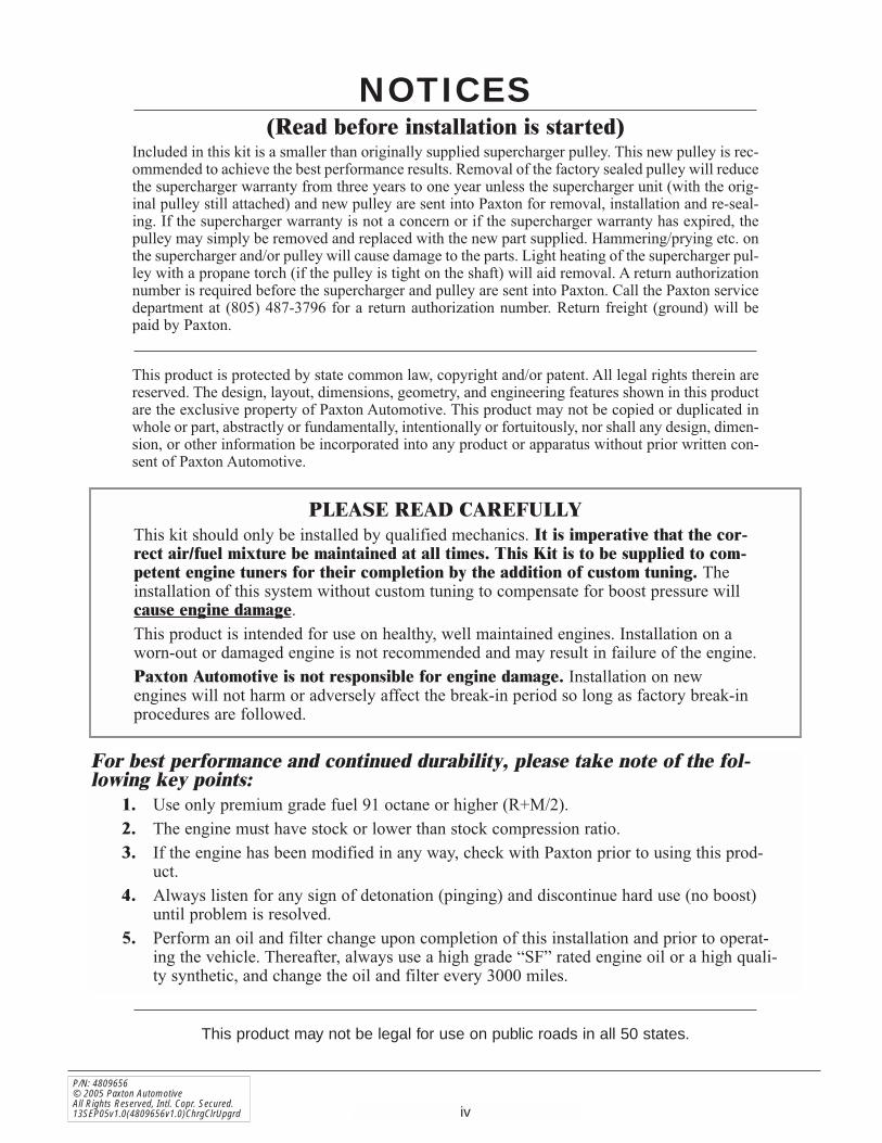
This product may not be legal for use on public roads in all 50 states.
NOTICES(Read before installation is started)
Included in this kit is a smaller than originally supplied supercharger pulley. This new pulley is rec-ommended to achieve the best performance results. Removal of the factory sealed pulley will reducethe supercharger warranty from three years to one year unless the supercharger unit (with the orig-inal pulley still attached) and new pulley are sent into Paxton for removal, installation and re-seal-ing. If the supercharger warranty is not a concern or if the supercharger warranty has expired, thepulley may simply be removed and replaced with the new part supplied. Hammering/prying etc. onthe supercharger and/or pulley will cause damage to the parts. Light heating of the supercharger pul-ley with a propane torch (if the pulley is tight on the shaft) will aid removal. A return authorizationnumber is required before the supercharger and pulley are sent into Paxton. Call the Paxton servicedepartment at (805) 487-3796 for a return authorization number. Return freight (ground) will bepaid by Paxton.
This product is protected by state common law, copyright and/or patent. All legal rights therein arereserved. The design, layout, dimensions, geometry, and engineering features shown in this productare the exclusive property of Paxton Automotive. This product may not be copied or duplicated inwhole or part, abstractly or fundamentally, intentionally or fortuitously, nor shall any design, dimen-sion, or other information be incorporated into any product or apparatus without prior written con-sent of Paxton Automotive.
PLEASE READ CAREFULLYThis kit should only be installed by qualified mechanics. It is imperative that the cor-rect air/fuel mixture be maintained at all times. This Kit is to be supplied to com-petent engine tuners for their completion by the addition of custom tuning. Theinstallation of this system without custom tuning to compensate for boost pressure willcause engine damage.This product is intended for use on healthy, well maintained engines. Installation on aworn-out or damaged engine is not recommended and may result in failure of the engine. Paxton Automotive is not responsible for engine damage. Installation on newengines will not harm or adversely affect the break-in period so long as factory break-inprocedures are followed.
For best performance and continued durability, please take note of the fol-lowing key points:
1. Use only premium grade fuel 91 octane or higher (R+M/2).2. The engine must have stock or lower than stock compression ratio.3. If the engine has been modified in any way, check with Paxton prior to using this prod-
uct.4. Always listen for any sign of detonation (pinging) and discontinue hard use (no boost)
until problem is resolved.5. Perform an oil and filter change upon completion of this installation and prior to operat-
ing the vehicle. Thereafter, always use a high grade “SF” rated engine oil or a high quali-ty synthetic, and change the oil and filter every 3000 miles.

P/N: 4809656© 2005 Paxton Automotive
All Rights Reserved, Intl. Copr. Secured.13SEP05v1.0(4809656v1.0)ChrgClrUpgrdv
PAXTON CHARGE COOLER Installation Instructions
2005 Ford 4.6 Mustang GT (3-Valve)
Before beginning this installation,please read through this entire instruction booklet
This Paxton Air/Air Charge Cooler system was designed as a street/strip oriented chargecooler, specifically for use on 2005 Ford 4.6 Mustang vehicles equipped with a Paxtonsupercharger.
As with any power enhancing product, this system is intended for use on healthy, well-maintained engines. Paxton Automotive is not responsible for engine damage. Installationon new vehicles will not harm or adversely affect the break-in period so long as factorybreak-in procedures are followed.
TOOL & SUPPLY REQUIREMENTS:
• Open End Wrenches: SAE and Metric• Allen Wrenches: SAE• Flat #2 Screwdriver• Phillips #2 Screwdriver• Wire Cutters, Strippers and Crimpers• Tape Measure• Pipe Tape (Teflon)• Adjustable Wrench• 7/8" Hole Saw• Tap - 5/16-18• 1/2" Drive Ratchet• 3/8" Drive and Socket Set: SAE and Metric• 9/16" Box end Ratchet Wrench (highly recommended)

P/N: 4809656© 2005 Paxton AutomotiveAll Rights Reserved, Intl. Copr. Secured.13SEP05v1.0(4809656v1.0)ChrgClrUpgrd vi
PART NO. DESCRIPTION QTY. PART NUMBER DESCRIPTION QTY.
IMPORTANT: Before beginning installation, verify that all parts are included in the kit. Report any shortages or damaged parts immediately.
2005 Mustang GT, H.O. UpgradePart No. 1300005
PARTS LISTS U P E R C H A R G E R S
2A036-348 S/C PULLEY 3.48" 6-GROOVE 15A001-025 DIABLE MAFia, '05 MUS 18R101-001 PULLEY RETAINER ASY 6-RIB 1
2A040-011 PULLEY RETAINER S/C 17B372-110 3/8-24 x 1" GRADE 8 HXHD 17K375-040 3/8"AN960 FLAT WASHER PLATED 17U100-070 KEY, 3/16" SQUARE x 7/8" LONG 1
4809655 MANUAL, H.0. UPGRADE 18PN201-050 CAC ASSY, '05 GT AIR/AIR 1
8PN101-050 WELDED CORE ASSY, '05 MUS GT 14PFU012-021 DISCH DUCT, T/B '05 MUSTANG 14PFU012-030 CAC TUBE, “A” '05 MUS GT 14PFU012-040 CAC TUBE, “B” '05 MUS GT 14PFU012-050 CAC TUBE, “C” '05 MUS GT 14PFU012-060 CAC TUBE, “D” '05 MUS GT 14PFU012-070 CAC TUBE, “E” '05 MUS GT 17PS300-301 BUMP HOSE, Ø3.00" x 3.00"L 37PS300-300 SLEEVE, BLACK, Ø3.00" x 3.00"L 27R002-048 #48 SAE TYPE “F” SS HOSE CLAMP 147R002-072 #72 SAE TYPE “F” SS HOSE CLAMP 27S300-003 RUBBER ELBOW 3" MODIFIED 27PS450-200 SLEEVE, BLACK Ø4.5" x 2.0"L 12A017-036 SPACER, PLTBRGHSG, 0186" 47C080-035 M8 x 125 x 35 BLT CL88 47F008-020 NUT, M8 x 125 47J312-000 5/16" FLAT WASHER-SAE 107R002-044 #44 SAE TYPE “F” SS HOSE CLAMP 17A312-050 5/16-18 x 1/2" HXHD GR5, ZINC 28PN010-030 SUPPRT, '05 MUST COOLR DUCT, ZN 27R002-016 #16 SAE TYPE “F” SS HOSE CLAMP 87P156-082 5/32" TEE 27U030-046 5/32" VACUUM LINE 8'8D001-001 STD COMPRESS BYPASS VALVE 27U133-100 HOSE, ELBOW, 90°, 1"ID, MOLDED 17U034-016 1" GS HEATER HOSE 25'7P750-100 3/4"NPT x 1" HOSE FITTING 17P218-156 VAC TEE, 7/32", 7/32", 5/32" 17U100-055 TIE-WRAP, 7.5" NYLON 4
7P750-100 3/4"NPT x 1" HOSE FITTING 18N155-080 COOLANT RES RELOC, '05 MUST 1
8N055-080 TANK, RAD OVERFLOW, '05 MUST 14FU010-051 MTG BRKT “A”, RES RELOC '05 MUST 14FU010-061 BRKT “B”, COOL RES RELOC '05 MUST 17A250-051 1/4-20 x 50 HHCS ZINC PLTD 47P250-045 1/4" MALE NPT x 3/8" MALE BARB 17J006-093 6mm WASHER, PLATED 47R002-010 #10 SAE TYPE “F” SS HOSE CLAMP 17P375-050 3/8" HOSE UNION, BRASS 17U030-056 3/8" PCV/VAC RUBBER HOSE 2.5'7R004-002 STEPLESS CLAMP, 170-70 37C060-020 M6 x 10 x 20mm HHCS ZN 37J006-093 6mm WASHER, PLATED 3
7PS275-100 SLEEVE, 2.75"ID x 1" 1

1-1
P/N: 4809656© 2005 Paxton Automotive
All Rights Reserved, Intl. Copr. Secured.13SEP05v1.0(4809656v1.0)ChrgClrUpgrd
A. Disconnect the battery.B. Remove the six nylon clips retaining the
upper radiator core support cover. (See Fig. 1-a.)
C. Loosen the four hose clamps securing thesupercharger discharge tube from the super-charger to the throttle body. Disconnect theby-pass valve hoses where they connect to theinlet and discharge tubes. Disconnect the by-pass valve vacuum line where it connects atthe fuel rail. Set the by-pass valve aside to bereinstalled in a later step. Remove the dis-charge tube and set it aside. It will not bereused.
D. Unplug the MAF connection from the meter.Loosen the hose clamps securing the inletducts to the supercharger and inlet duct sup-port bracket. Remove the inlet duct assemblyand set it aside to be reinstalled in a later step
E. Disconnect the oil feed and oil drain lines.
*** NOTE ***Temporarily cap the oil lines to protect yourengine from foreign particles.
F. Using a 1/2" ratchet wrench loosen the acces-sory belt tensioner and remove the belt fromthe supercharger pulley only. Tie the belt backaway from the supercharger temporarily.
G. Remove the five 9/16" headed screws secur-ing the supercharger to its mounting plate.
*** NOTE ***A 9/16" ratchet wrench will greatly aid in this step.
H. Remove the supercharger from the vehicle.
Fig. 1-a
NYLON CLIPS
1. PREPARATION AND REMOVAL
Section 1PREPARATION AND REMOVAL

1-2
P/N: 4809656© 2005 Paxton AutomotiveAll Rights Reserved, Intl. Copr. Secured.13SEP05v1.0(4809656v1.0)ChrgClrUpgrd
Fig. 1-b
Fig. 1-c
8mm HEADED BOLTS
COOLANTOVERFLOW HOSE
TWO UPPERRADIATOR HOSES
HOSE TOTHERMOSTAT
I. Locate the coolant drain plug on the passen-ger side of the radiator. Next drain the coolantinto a clean container. This coolant will bereused in a later step.
J. Remove the two 8mm headed bolts securingthe coolant overflow reservoir to the plasticfan shroud. (See Fig. 1-b.)
K. Disconnect the small overflow hose (runningacross the top of the radiator) from the over-flow reservoir. (See Fig. 1-b.)
*** NOTE ***Retain only the fill cap for reuse.
L. Remove the large hose connecting the thermo-stat hose to the bottom of the overflow reser-voir. The hose and overflow reservoir will notbe reused. (See Fig. 1-c.)

2-1
P/N: 4809656© 2005 Paxton Automotive
All Rights Reserved, Intl. Copr. Secured.13SEP05v1.0(4809656v1.0)ChrgClrUpgrd
Fig. 2-a
A. Place the supercharger on a clean flat surfacewith the drive pulley facing up.
B. Loosen and remove the six 1/4-20 cap screwsand retaining plates that hold the compressorhousing to the gearcase.
C. Carefully rotate the supercharger volute to thespecified location as shown. (See Fig. 2-a.)
D. Evenly retighten the six (6) cap screws, torqueto 60 in/lbs (5ft/lbs).
E. Remove original 3.80" supercharger pulleyfrom the supercharger and install the supplied3.48" pulley.
*** NOTE ***Included in this kit is a smaller than originallysupplied supercharger pulley. This new pulley isrecommended to achieve best performanceresults. Removal of the factory sealed pulley willreduce the supercharger warranty from threeyears to one year unless the supercharger unit(with the original pulley still attached) and newpulley are sent into Paxton for removal, installa-tion and re-sealing. If supercharger warranty isnot a concern or if the supercharger warranty hasexpired, the pulley may simply be removed andreplaced with the new part supplied.Hammering/prying etc. on the superchargerand/or pulley will cause damage to the parts.Light heating of the supercharger pulley with apropane torch (if the pulley is tight on the shaft)will aid removal. A return authorization number isrequired before the supercharger and pulley aresent into Paxton. Call the Paxton service depart-ment at (805) 604-1336 for return authorizationnumber. Return freight (ground) will be paid byPaxton.
*** NOTE ***If the compressor housing does not rotate freelyrelative to the gearcase, DO NOT FORCE IT. SERI-OUS SUPERCHARGER DAMAGE MAY OCCUR. Themachined mating surfaces are designed to preventpressurized air from escaping and have minimaltolerances. If the housing will not move or is verytight, contact Paxton Automotive immediately at(805) 604-1336 and ask for our service departmentfor further assistance.
2. SUPERCHARGER RECLOCKING ANDREINSTALLATION
Section 2SUPERCHARGER RECLOCKING AND REINSTALLATION

2-2
P/N: 4809656© 2005 Paxton AutomotiveAll Rights Reserved, Intl. Copr. Secured.13SEP05v1.0(4809656v1.0)ChrgClrUpgrd
F. Remove the 3.5" plastic idler, retainer andwasher. Carefully reposition the idler and itstwo spacers to the lower mounting hole justbelow its current position. Reinstall the retain-er previously removed and tighten. (See Fig.2-b.)
G. Install the five 3/8-16 x 1.0" bolts and wash-ers through the back side of the mountingplate. (See Fig. 2-b.)
H. Secure the supercharger assembly to themounting plate using the previously installedhardware. A 9/16" ratcheting end wrench willgreatly aid this step.
I. Secure the oil drain hose to the installed brassfitting in the oil pan, making sure to route in asmooth downward manner away from movingor hot objects.
*** NOTE ***Any dips, “uphill” sections, kinks or restrictionsmay cause drainage problems and possiblesupercharger failure.
J. Attach the -4 oil feed hose to the straight -4fitting installed in the supercharger. Secureaway from moving or hot objects.
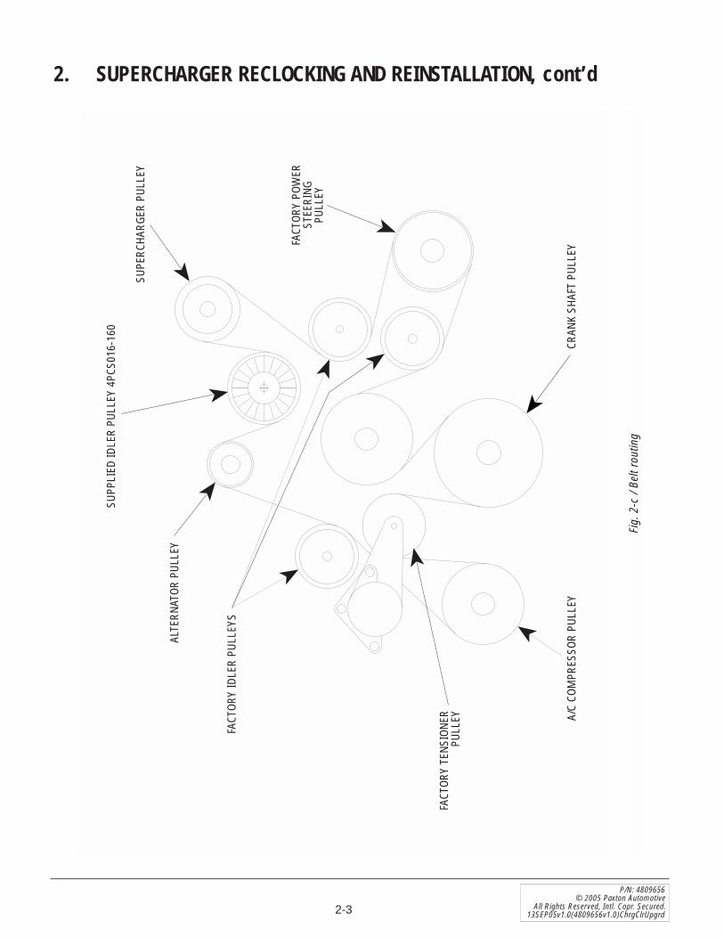
K. Using a 1/2" ratchet, rotate the factory springtensioner clockwise and install the accessorydrive belt. Refer to Fig. 2-c for proper beltrouting.
2. SUPERCHARGER RECLOCKING AND REINSTALLATION, cont’d
Fig. 2-b
SUPERCHARGER HARDWARE
IDLER RETAINERMOVE IDLERTO LOWER
MOUNTING HOLE
2-3
P/N: 4809656© 2005 Paxton Automotive
All Rights Reserved, Intl. Copr. Secured.13SEP05v1.0(4809656v1.0)ChrgClrUpgrd
Fig.
2-c
/ Be
lt ro
utin
g
A/C
COM
PRES
SOR
PULL
EY
FACT
ORY
TENS
IONE
RPU
LLEY
ALTE
RNAT
OR P
ULLE
Y
SUPP
LIED
IDLE
R PU
LLEY
4PC
S016
-160
FACT
ORY
POW
ERST
EERI
NGPU
LLEY
CRAN
K SH
AFT
PULL
EY
FACT
ORY
IDLE
R PU
LLEY
S
SUPE
RCHA
RGER
PUL
LEY
2. SUPERCHARGER RECLOCKING AND REINSTALLATION, cont’d

2-4
P/N: 4809656© 2005 Paxton AutomotiveAll Rights Reserved, Intl. Copr. Secured.13SEP05v1.0(4809656v1.0)ChrgClrUpgrd
This Page Left Intentionally Blank

3-1
P/N: 4809656© 2005 Paxton Automotive
All Rights Reserved, Intl. Copr. Secured.13SEP05v1.0(4809656v1.0)ChrgClrUpgrd
*** NOTE ***For non-cooled kits skip this section and proceedto Section 9.
A. BUMPER COVER AND SPLASH PAN
1. Raise the vehicle with a floor jack and seton jack stands.
2. Remove the seven 5.5mm headed screwsretaining the lower splash panel. (See Fig.3A-a.)
3. Remove the six Phillips-head screws (3each side) on the lower portions of theplastic inner fender liners. (See Fig. 3A-b.)
4. Remove the five plastic clips securing thefront portion of the fender liner. Both sidesneed to be removed. (See Fig. 3A-c.)
5. Remove the four 10mm nuts (2 each side)retaining the bumper cover to the fenders.(See Fig. 3A-d.)
3. CHARGE AIR COOLER INSTALLA-TION
Fig. 3A-a
Fig. 3A-b
Fig. 3A.c
Section 3CHARGE AIR COOLER INSTALLATION
Fig. 3A-d
10mm HEADEDBOLTS
PHILLIPS-HEAD SCREWS
SPLASHPANELS

6. Disconnect the connectors on the parkingand the lower fog lights. (See Fig. 3A-e.)
7. Remove the six nylon clips retaining theupper radiator core support cover. (SeeFig. 3A-f.)
8. Remove the two 10mm headed bolts (1each side upper portion of grill). (See Fig.3A-g.)
Fig. 3A-e
Fig. 3A-g
Fig. 3-f
NYLON CLIPS
10mm HEADED BOLT
LIGHT CONNECTIONS
10. Pull out on the bumper cover11. Remove the connectors to the driving
lights in the grill. (See Fig. 3A-h.)12. Remove the bumper cover and set aside.
(See Fig. 3A-i.)
9. Lift up on the tabs releasing them from theclips. (See Fig. 3A-h.)
Fig. 3A-h
DRIVING LIGHTCONNECTOR
3-2
P/N: 4809656© 2005 Paxton AutomotiveAll Rights Reserved, Intl. Copr. Secured.13SEP05v1.0(4809656v1.0)ChrgClrUpgrd
3. CHARGE AIR COOLER INSTALLA-TION, cont’d

3-3
P/N: 4809656© 2005 Paxton Automotive
All Rights Reserved, Intl. Copr. Secured.13SEP05v1.0(4809656v1.0)ChrgClrUpgrd
3. CHARGE AIR COOLER INSTALLA-TION, cont’d
Fig. 3A-i
Fig. 3A-j
Fig. 3A-k
13mm HEADED BOLTS
NYLON PUSH PINS
15. Replace the bolts previously removedwith the four 8mm x 1.25" x 35mm longbolts and washers provided.
16. Install the four 2A017-036 spacers (twoeach side) to the bolts. (See Fig. 3A-l.)
14. Remove four inner bolts of eight 13mmheaded bolts retaining the metal bumpersupport. (See Fig. 3A-k.)
13. Remove four nylon push pins from thestyrofoam bumper support and set thesupport and the pins aside to be rein-stalled. (See Fig. 3A-j.)
Fig. 3A-l
SPACERSPROVIDED
17. Replace the styrofoam bumper support usingthe factory retainers.

3-4
P/N: 4809656© 2005 Paxton AutomotiveAll Rights Reserved, Intl. Copr. Secured.13SEP05v1.0(4809656v1.0)ChrgClrUpgrd
3. Using a 3" x 3" bump sleeve, 2.75"ID x1" long sleeve. and two #48 hose clamps,loosely attach tube “A” to the supercharg-er discharge.
*** NOTE ***The 2.75"ID x 1" long sleeve should be placed onthe supercharger discharge first, then attach the3" x 3" bump sleeve.
*** NOTE ***The by-pass port should be facing the driver’sside
4. Attach tube “B” using a second 3" x 3"bump sleeve and the provided #48 hoseclamps to the open end of tube “A”.
*** NOTE ***For better duct clearance, rotate the power steer-ing return fitting so that it points to the front ofthe vehicle. Use care not to damage the fitting orhose. If necessary, rotate the power steering linefrom the rack to the radiator closer to the frame.(See Fig. 3B-d.)
B. CHARGE AIR COOLER ASSEMBLY
3. CHARGE AIR COOLER INSTALLA-TION, cont’d
Fig. 3B-c
Fig. 3B-d
SHORT ENDS OF 90°ELBOWS PROVIDED
FITTING ROTATED TOWARDFRONT OF VEHICLE
*** NOTE ***Use Fig. 3B-a to aid in the next few steps
1. Locate the Charge Air Cooler assembly.Place the cooler onto the previouslyinstalled hardware, making sure the fourspacers remain in place. Align the top ofthe cooler flush with the top of the styro-foam bumper support. Secure the coolerusing the nuts and washers provided. (SeeFig. 3-b.)
2. Loosely install the short ends of the two90° rubber elbows onto each end of thecharge cooler using the supplied #48 hoseclamps. (See Fig. 3B-c.)
Fig. 3B-a
Fig. 3B-b
TUBE “A”
TUBE “B”
TUBE “C” TUBE “D”
TUBE “E”
DISCHARGE DUCT CHARGE COOLER
FLUSH WITH TOP

3-5
P/N: 4809656© 2005 Paxton Automotive
All Rights Reserved, Intl. Copr. Secured.13SEP05v1.0(4809656v1.0)ChrgClrUpgrd
3. CHARGE AIR COOLER INSTALLA-TION, cont’d
Fig. 3B-e | Driver’s side Fig. 3B-g | Passenger’s side
Fig. 3B-f
Fig. 3B-h
5. Install the provided 3" x 3" sleeve and#48 hose clamps onto the open end oftube “B”.
6. Using a 5/16-18 tap, tap the lower hole onthe driver’s and passenger’s side core sup-port. Locate the tube support brackets,5/16-18 x 1/2" screws and washers.Loosely attach the tube support bracketsto the core support. (See Fig. 3B-e, 3B-g.)
7. Install tube “C” between the 90° rubberelbow and the 3" x 3" sleeve previouslyinstalled on tube “B”. Attach tube “C” to itssupport bracket using the #44 hose clamp.Tighten the clamp and bracket. Secure allhose connections to this point using the #48hose clamps provided adjusting for best fitand clearance.
8. Install the short end of tube “D” into theopen end of the passenger’s side 90° rubberelbow previously install. (See Fig. 3B-f.)
9. Attach a 3" x 3" sleeve and #48 hoseclamps to the open end of tube “D”.
10. Install the short end of tube “E” into thesleeve attached to tube “D”. Secure thetube support bracket using the previouslyinstalled #48 hose clamp. (See Fig. 3B-g.)
*** NOTE ***For better fit, the transmission cooler lines (ifequipped) will need to be pushed upward slightlyso that tube “E” will fit between them and the A/Ccompressor. (See Fig. 3B-g.)
11. Attach the cast discharge duct to the throt-tle body using the supplied 4.5" sleeveand #72 hose clamps.
12. Using the remaining 3" x 3" bump sleeveand #48 hose clamps, connect the longend of tube “E” to the cast discharge tube.(See Fig. 3B-h.)
13. Secure all hose connections at this time,adjusting for best fit and clearance.
TUBE “C”
UPPERHOLE
LOWER HOLE TAPPEDWITH BRACKET INSTALLED
TUBE “D”TUBE “E”
DISCHARGE DUCT
TUBESUPPORTBRACKET
SHORT ENDOF TUBE “E”

3-6
P/N: 4809656© 2005 Paxton AutomotiveAll Rights Reserved, Intl. Copr. Secured.13SEP05v1.0(4809656v1.0)ChrgClrUpgrd
3. CHARGE AIR COOLER INSTALLA-TION, cont’d
C. COMPRESSOR BYPASS VALVE ASSEMBLYINSTALLATION
1. Bypass valve #1:a. Cut a piece of the provided 1" heater
hose approximately 3" long andsecure it to the by-pass valve inlet(opposite the vacuum port) using the#16 hose clamps provided.
b. Locate the 1" molded rubber 90°elbow and cut approximately 6" fromthe long end and 1" from the shortend. Attach the long end to the by-pass valve discharge and secure usingthe #16 hose clamps provided. (SeeFig. 3C-a, 3C-d.)
c. Attach the open end of the 3" longhose to the by-pass port on tube “A”and secure using a #16 hose clamp.The open end of the 90° hose will beconnected to the inlet duct in a laterstep. See Fig. 3C-d.)
Fig. 3C-a
3" x Ø1" HOSE (TRIM TO FIT)TO DISCHARGE TUBE “A” BY-PASS VALVE (TRIM TO APPROX. 5.75")
(TRIM TOAPPROX. 4")
7U133-100 MOLDED 90° HOSETRIM TO FIT
TO INLET DUCT

3-7
P/N: 4809656© 2005 Paxton Automotive
All Rights Reserved, Intl. Copr. Secured.13SEP05v1.0(4809656v1.0)ChrgClrUpgrd
Fig. 3C-b
3. CHARGE AIR COOLER INSTALLA-TION, cont’d
2. Bypass valve #2:a. Cut a piece of the supplied 1" heater
hose 4.5" long and a piece 15" long.b. Attach the 4.5" piece of hose to the
inlet of the by-pass valve, securing itwith a #16 hose clamp.
4.5" x Ø1" HOSE(TRIM TO FIT)
TO DISCHARGETUBE AT THE
THROTTLE BODY
15" x Ø1" HOSE(TRIM TO FIT)
TO MANIFOLD PRESSURE/VACUUM
#16 HOSE CLAMPS
BYPASSVALVE
TO INLETDUCT
c. Secure the 15" piece to the by-passvalve discharge using a #16 hoseclamp.
d. Attach the open end of the 4.5" hoseto the by-pass port on the cast dis-charge duct and secure using a #16hose clamp. The open end of the 15"long hose will be attached to the inletduct in a later step. (See Fig. 3C-b,3C-d.)

3-8
P/N: 4809656© 2005 Paxton AutomotiveAll Rights Reserved, Intl. Copr. Secured.13SEP05v1.0(4809656v1.0)ChrgClrUpgrd
3. CHARGE AIR COOLER INSTALLA-TION, cont’d
e. Attach a length of 5/32" vacuum hoseto bypass valve #2 and route to thevacuum port of the fuel rail sensor.
f. Cut a section of the factory hose andinstall the vacuum TEE that is provid-ed. (See Fig. 3C-c.)
g. Attach the vacuum hose from thebypass valve to the TEE.
h. Attach a length of 5/32" vacuum hoseto the previously installed bypassvalve #1. Connect the open end to thepreviously installed vacuum line run-ning to the fuel rail from bypass #2using the TEE provided. (See Fig.3C-d.)
Fig. 3C-c
VACUUM TEE
VACUUM HOSE

3-9
P/N: 4809656© 2005 Paxton Automotive
All Rights Reserved, Intl. Copr. Secured.13SEP05v1.0(4809656v1.0)ChrgClrUpgrd
3. CHARGE AIR COOLER INSTALLA-TION, cont’d
BYPA
SSVA
LVE
VIEW
FRO
M F
RONT
OF
VEHI
CLE
#16
HOSE
CLAM
PS O
N AL
LHO
SE E
NDS
PO
RT
ON
THR
OTT
LEB
OD
Y D
UC
T
4.5"
LEN
GTH
OF H
OSE
15" L
ENGT
H OF
HOS
E
VACU
UM T
EE A
TFU
EL R
EGUL
ATOR
3" L
ENGT
H OF
HOS
EBY
-PAS
SVA
LVE
TO 9
0° R
UBBE
R HO
SEAP
PROX
.5.
75"
VACU
UM T
EE
APPR
OX. 4
"
TO S
TRAI
GHT
FITT
ING
ONIN
LET
DUCT
7U13
3-10
0 M
OLDE
D90
° HOS
E
TUBE
“A”
Fig.
3C-
d

3-10
P/N: 4809656© 2005 Paxton AutomotiveAll Rights Reserved, Intl. Copr. Secured.13SEP05v1.0(4809656v1.0)ChrgClrUpgrd
Fig. 3D-c
2. Detach the wiring harness from the retain-ing clips and move the harness to theshock tower. Secure the harness to the A/Cline with wire ties. (See Fig. 3D-b.)
3. Remove the small clip retaining the smallwiring harness to the shock tower. (SeeFig. 3D-b.)
4. Attach the small harness to the large har-ness with wire ties.
5. To gain clearance for the coolant reservoirthe A/C line will need to be bent slightlytowards the passenger’s side fender. (SeeFig. 3D-b.)
6. Remove the 10mm headed screw retainingthe ground strap to the bracket on the struttower. (See Fig. 3D-c.)
Fig. 3D-b
3. CHARGE AIR COOLER INSTALLA-TION, cont’d
D. WIRING HARNESS RELOCATION
1. On the passenger’s side of the engine,attached to the valve cover, is a large wireharness. The harness will have to be relo-cated to gain clearance for the radiatoroverflow reservoir. (See Fig. 3D-a.)
Fig. 3D-a
SECURE HARNESSWITH WIRE-TIES
BENT A/C LINE

3-11
P/N: 4809656© 2005 Paxton Automotive
All Rights Reserved, Intl. Copr. Secured.13SEP05v1.0(4809656v1.0)ChrgClrUpgrd
4. Locate and install 1/4"NPT x 3/8" barbedfitting in the tapped hole just above thepreviously installed mounting bracket.This hole may have to be opened using theappropriate drill bit. (See Fig. 3E-c.)
Fig. 3E-c
Fig. 3E-b
Fig. 3E-a
E. ENGINE COOLANT RESERVOIR INSTALLA-TION
1. Locate assembly 8N155-080.2. Attach the rear reservoir mounting bracket
4FU010-051 to the reservoir with the 1/4-20 x 3/4" long bolts and washers provided.(See Fig. 3E-a.)
3. CHARGE AIR COOLER INSTALLA-TION, cont’d
3. Attach bracket 4FU010-061 to the front ofthe reservoir with the hardware provided.(See Fig. 3E-b.)
BRACKET
3/8" BARBEDFITTING
3-12
P/N: 4809656© 2005 Paxton AutomotiveAll Rights Reserved, Intl. Copr. Secured.13SEP05v1.0(4809656v1.0)ChrgClrUpgrd
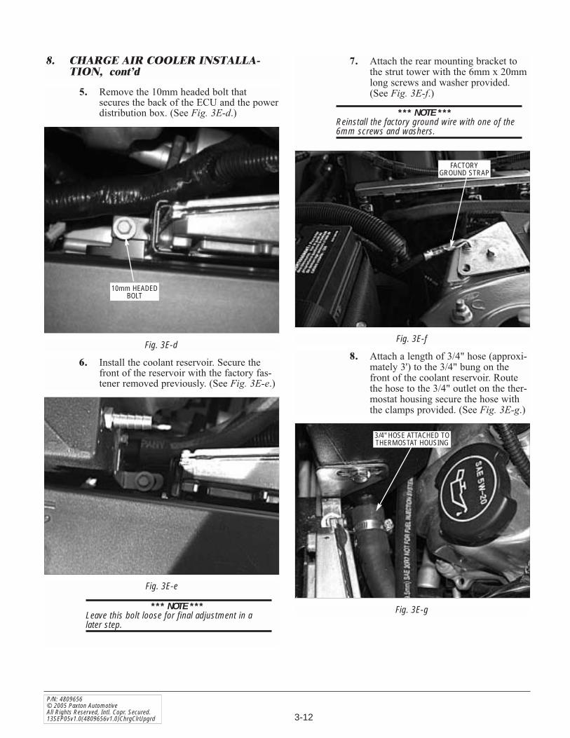
5. Remove the 10mm headed bolt thatsecures the back of the ECU and the powerdistribution box. (See Fig. 3E-d.)
6. Install the coolant reservoir. Secure thefront of the reservoir with the factory fas-tener removed previously. (See Fig. 3E-e.)
*** NOTE ***Leave this bolt loose for final adjustment in alater step.
Fig. 3E-d
Fig. 3E-e
7. Attach the rear mounting bracket tothe strut tower with the 6mm x 20mmlong screws and washer provided.(See Fig. 3E-f.)
*** NOTE ***Reinstall the factory ground wire with one of the6mm screws and washers.
8. Attach a length of 3/4" hose (approxi-mately 3') to the 3/4" bung on thefront of the coolant reservoir. Routethe hose to the 3/4" outlet on the ther-mostat housing secure the hose withthe clamps provided. (See Fig. 3E-g.)
10mm HEADEDBOLT
8. CHARGE AIR COOLER INSTALLA-TION, cont’d
Fig. 3E-f
FACTORYGROUND STRAP
Fig. 3E-g
3/4" HOSE ATTACHED TOTHERMOSTAT HOUSING

3-13
P/N: 4809656© 2005 Paxton Automotive
All Rights Reserved, Intl. Copr. Secured.13SEP05v1.0(4809656v1.0)ChrgClrUpgrd
3. CHARGE AIR COOLER INSTALLA-TION, cont’d
Fig. 3E-i
Fig. 3E-j
9. Modify the small hose removed from thefactory coolant overflow reservoir. By cut-ting the “S” bend off the hose end. (SeeFig. 3E-h.)
10. Install a 3/8" union and a #17 steplessclamp. Secure the clamp. Using a length of3/8" (approximately 30" long) hose that isprovided, secure the hose to the union witha #17 stepless clamp. (See Fig. 3E-i.)
11. Route the overflow hose across the radia-tor and under the radiator retaining bracketto the 1/4"NPT x 3/8" hose barb fitting inthe coolant reservoir securing with aclamp. (See Fig. 3E-j.)
12. Check to see that all hose connections aresecure.
13. Refill the coolant system using the factorycoolant (if in good condition). Use the fac-tory radiator cap saved during a previousstep.
14. Reinstall the front bumper assemblyincluding the foam inner bumper, all plas-tic splash panels and light connections inthe reverse order removed.
Fig. 3E-h
TRIM FAN SHROUDAS NEEDED FOR
HOSE CLEARANCE
FACTORYCOOLANT HOSE

3-14
P/N: 4809656© 2005 Paxton AutomotiveAll Rights Reserved, Intl. Copr. Secured.13SEP05v1.0(4809656v1.0)ChrgClrUpgrd
This Page Left Intentionally Blank

4-1
P/N: 4809656© 2005 Paxton Automotive
All Rights Reserved, Intl. Copr. Secured.13SEP05v1.0(4809656v1.0)ChrgClrUpgrd
4. AIR INLET ASSEMBLY
Section 4AIR INLET ASSEMBLY
A. Remove two of the 3/8-16 x 1" bolts securingthe supercharger in place. Install the air inletsupport bracket and secure with the 3/8" boltsremoved from the supercharger mounting plate.(See Fig. 4-a.)
B. Attach the 4.0 x 3.5 reducer sleeve to the inletduct. Secure the sleeves with the clamps pro-vided. (See Fig. 4-c.)
C. Using a 7/8" hole saw, drill the secondary by-pass provision. Be careful not to damage theplastic threads.
D. Apply a small amount of pipe sealant to thesupplied 3/4"NPT to 1" straight barb fitting.Install the fitting in the previously drilled hole.(See Fig. 4-b.)
E. Attach the open end of the previoulsy installed1" x 90° hose to the 1" straight barb fitting andsecure with a #16 hose clamp provided.
Fig. 4-a
Fig. 4-c
Fig. 4-b
3/4"NPT x 1" x 90°BARBED FITTING
3/4"NPTTO 1" BARB
1/4"NPT x 3/8" x 90°HOSE BARBED FITTING

4-2
P/N: 4809656© 2005 Paxton AutomotiveAll Rights Reserved, Intl. Copr. Secured.13SEP05v1.0(4809656v1.0)ChrgClrUpgrd
F. Attach the 1" bypass outlet hose to the 90°plastic fitting and secure the hose with a # 16hose clamp.
G. Re-attach the 3/8" hose to the 1/4"NPT x 3/8"hose x 90° fitting installed in the inlet duct.
H. Re-install the duct to the inlet of the super-charger and secure in place with the clampspreviously removed
I. Install the 180° duct and the MAF sensor withfilter to the inlet duct leading to theSupercharger.(See Figs. 4-d, 4-e.) Clock theMAF exactly as shown in the figure.
J. Secure the rear clamp at the inlet duct unionto the previously installed support bracket.(See Fig. 4-e.). Fig. 4-e
Fig. 4-d
AIR INLETSUPPORT BRACKET
4. AIR INLET ASSEMBLY, cont’d
K. MAF Interface Adapter Installation.1. If in the event you have received a MAF
Interface Adapter that is not a “plug in”unit, it will be necessary to modify theadapter as outlined in steps 2 & 3 below.Otherwise, plug the MAF interfaceadapter between the factory MAF and theMAF harness connector and ignore steps2 & 3 below.
2. Remove the connector that is attached tothe MAF Interface Adapter leave approxi-mately 2-3" of wire measured from theplug end.
3. Remove the factory MAF sensor plugfrom the car leaving an adequate length ofwire to be soldered to the wires of theMAF Interface Adapter. (Approximately2-3".)
*** NOTE ***It is strongly recommended that the wires be sol-dered. Temporary solderless connectors havebeen provided in case you are unable to solder.

4-3
P/N: 4809656© 2005 Paxton Automotive
All Rights Reserved, Intl. Copr. Secured.13SEP05v1.0(4809656v1.0)ChrgClrUpgrd
Fig. 4-f c(FOR H.O. Kits Only — Hard wire schematic for MAF Interface Adapter.)
4. AIR INLET ASSEMBLY, cont’d
4. Install the MAF Interface Adapter to thewires of the factory harness.
5. Install the factory MAF sensor connectorto the MAF adapter in place of the origi-nal MAF adapter connector.
6. Refer to the diagram provided for wirecolors and there locations.
7. Remove the small red cover in the middleof the supplied MAF Interface Adapterbox.
8. Verify that the MAF Interface Adapterbox is set on number “2”.
RED
GREYGREY/BLACKBLACK/WHITETAN/GREENBLUE/RED
PURPLE/TAN
GREYGREY/BLACKBLACK/WHITETAN/GREENBLUE/RED
FACTORYWIRE
HARNESS
MAFINTERFACEADAPTER
NOTE: SOME VEHICLES MAY HAVE A RED WIRE IN PLACE OF THE PURPLE/TAN WIRE.
FACTORY MAFSENSOR PLUG
MAF INTERFACE PLUG TO BE REMOVED FACTORY MAF SENSOR PLUG TO BE REMOVED
RED
GREYGREY/BLACKBLACK/WHITETAN/GREENBLUE/RED
PURPLE/TAN
GREYGREY/BLACKBLACK/WHITETAN/GREENBLUE/RED
MAF INTERFACE ADAPTER PLUG REMOVEDFROM MAF INTERFACE HARNESS
9. If you find that the MAF InterfaceAdapter box in not set, use the tool that isprovided with the MAF Interface Adapterbox and set to number “2”.
10. Replace the cover and secure the MAFInterface Adapter box away from hot ormoving parts with nylon ties.
*** NOTE ***It is critical that the MAF Interface Adapter boxbe set on number “2”, The calibration that is pro-vided with this kit has been created to work atthis setting. Any change to the MAF InterfaceAdapter box by setting it to a higher or lowernumber could cause damage to the engine.

4-4
P/N: 4809656© 2005 Paxton AutomotiveAll Rights Reserved, Intl. Copr. Secured.13SEP05v1.0(4809656v1.0)ChrgClrUpgrd
This Page Left Intentionally Blank

5-1
P/N: 4809656© 2005 Paxton Automotive
All Rights Reserved, Intl. Copr. Secured.13SEP05v1.0(4809656v1.0)ChrgClrUpgrd
Section 5FINAL CHECK
5. FINAL CHECK
*** NOTE ***Do not attempt to operate the vehicle until ALLcomponents are installed and ALL operations arecompleted including the final check.
A. Check all fittings, hose and clamps for tight-ness and leaks. Make sure all wires and linesare properly secure with clamps or tie-wraps.
B. Make sure all wires and hoses are routedaway from hot, moving or sharp objects.
C. Custom Tuning: This kit requires customECM calibration before the vehicle is to bedriven at any throttle opening greater than50%. Calibration by a competent tuner with awide band 02 sensor and timing monitoringequipment is required.
D. Test drive the vehicle.E. Always listen carefully for engine detonation.
Discontinue heavy throttle usage if detonationis heard.

DP/N: 4809656 - v1.0 09/13/05
S U P E R C H A R G E R SPaxton Automotive . 1300 Beacon Place . Oxnard CA 93033
805 604-1336 . FAX • 805 604-1337