s pecial dition aper - jreast.co.jp · s pecial dition aper ... than 20 years, so disadvantages...
TRANSCRIPT

47JR EAST Technical Review-No.34
Special edition paper
JR East has built and operated a condition monitoring system for monitoring signal equipment. However, more than 20 years have passed since the start of operation of the system, and now stable operation, transmission of more detailed information, easy construction, easy maintenance, and the like need to be handled. To achieve a new method that can handle those demands and be put into operation even in the severe wayside environment and meet those needs, we conducted a study on a wireless condition monitoring.
1.1 Signal Equipment and Condition Monitoring SystemThere are many types of signal equipment, including signals, level crossing protection devices, ATS, motor point machines, track circuits, and interlocking devices, most of which are directly related to safe and stable operation of trains. If a failure occurs or might occur with any of those, the maintenance depot or other office in charge has to take immediate actions. The condition monitoring system (Fig. 1) supports such actions.
The condition monitoring system transmits information on the condition of signal equipment. More specifically, the system obtains failure information (contact point information) and operation information (analog data on voltage, current, etc.) of individual equipment by polling and transmits that information to a central unit. The system has a tree structure network hierarchy, so information is gathered by each level, and each component transmits the information by a procedure specified in advance.
1.2 Aiming for Wireless Condition MonitoringThe current condition monitoring system has been used for more than 20 years, so disadvantages such as slow communication speed and serious impact on the total system in the event of a defect of a component are becoming apparent. We therefore
Introduction1decided to develop a new condition monitoring system that uses radio communications. A major advantage of radio communications is that labor for installation and maintenance can be reduced, but there is concern about reliability of radio communications compared with cable communications. As the condition of signal equipment needs to be constantly monitored, we investigated the viability of condition monitoring by radio communications.
There are different standards for radio communications, and we adopted the ZigBee* (IEEE802.15.4) standard for short-range radio networks in this study because it seemed highly applicable from the perspective of aspects such as communication range and maximum number of connections. While transmission speed with ZigBee is relatively low, it allows hopping of data between terminals over a dynamic network. We found that this feature of ZigBee would work well with railway facilities where components are dotted along long lines. In terms of security, it is characterized by exclusive control of connection between terminals being possible using IDs and by AES128 being employed for data encryption.
Basic Tests and Development of Devices for the System2
For the ZigBee standard we selected, we verified applicability of general-purpose communication terminals, and then we developed new communication terminals for specific signal equipment.
2.1 Basic Tests and Development of Duplex ZigBeeFor the basic tests, we carried out hopping tests (data relayed between terminals), stress tests (simultaneous data transmission from terminals), interval tests (varied data transmission intervals from a terminal), and shielding penetration tests (whether or not radio waves penetrate shielding of metal, concrete, casting, or other material).
In those tests, we carried out measurements while varying volume of data to be transmitted, number of terminals, and transmission intervals, and we found that transmission speed remarkably drops when hopping more than 10 times and as volume of data to transmit becomes larger. Radio waves could penetrate shielding and allow transmission to some extent;
New System for Railway Signal Equipment Monitoring by Radio Communications
•Keywords: Condition monitoring, Signal equipment, Simultaneous communications, Radio, ZigBee, Duplexing
JR East has been operating a monitoring system for signal equipment. Hence, condition of signal equipment can be easily monitored at maintenance depots. But since this system was developed over 20 years ago, today it has some disadvantages. To achieve “stable operation”, “broadband data transfer” and “easy construction and easy maintenance”, we studied a new monitoring method using radio communications, especially focusing on ZigBee. We subsequently developed a new mechanism using two different radio bands simultaneously as a basic function. Finally, we developed several types of terminals, repeaters and base units and carried out field tests with them. Eventually, we obtained good results.
*Technical Center, Research and Development Center of JR East Group
Takumi Kobayashi*Yoshiyasu Kudo*Masahiko Suzuki*
Maintenance center
Dispatcher's office
Equipment room
Equipment cabinet
Motor pointmachine
Signal
Track circuit device
Level crossing equipment<Current, voltage, etc.>
Equipment room
Equipment cabinet
Fig. 1 Image of a Condition Monitoring System for Signal Equipment
48 JR EAST Technical Review-No.34
Special edition paper
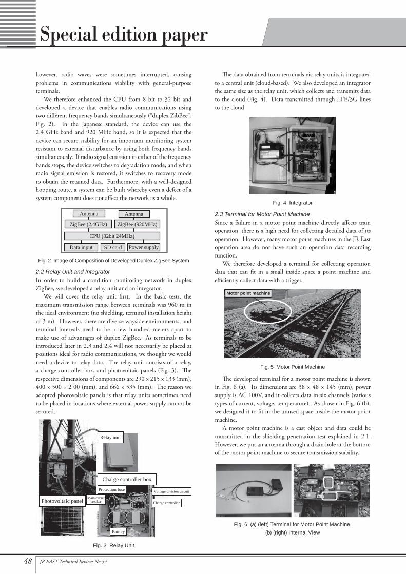
The data obtained from terminals via relay units is integrated to a central unit (cloud-based). We also developed an integrator the same size as the relay unit, which collects and transmits data to the cloud (Fig. 4). Data transmitted through LTE/3G lines to the cloud.
2.3 Terminal for Motor Point MachineSince a failure in a motor point machine directly affects train operation, there is a high need for collecting detailed data of its operation. However, many motor point machines in the JR East operation area do not have such an operation data recording function.
We therefore developed a terminal for collecting operation data that can fit in a small inside space a point machine and efficiently collect data with a trigger.
The developed terminal for a motor point machine is shown in Fig. 6 (a). Its dimensions are 38 × 48 × 145 (mm), power supply is AC 100V, and it collects data in six channels (various types of current, voltage, temperature). As shown in Fig. 6 (b), we designed it to fit in the unused space inside the motor point machine.
A motor point machine is a cast object and data could be transmitted in the shielding penetration test explained in 2.1. However, we put an antenna through a drain hole at the bottom of the motor point machine to secure transmission stability.
however, radio waves were sometimes interrupted, causing problems in communications viability with general-purpose terminals.
We therefore enhanced the CPU from 8 bit to 32 bit and developed a device that enables radio communications using two different frequency bands simultaneously (“duplex ZibBee”, Fig. 2). In the Japanese standard, the device can use the 2.4 GHz band and 920 MHz band, so it is expected that the device can secure stability for an important monitoring system resistant to external disturbance by using both frequency bands simultaneously. If radio signal emission in either of the frequency bands stops, the device switches to degradation mode, and when radio signal emission is restored, it switches to recovery mode to obtain the retained data. Furthermore, with a well-designed hopping route, a system can be built whereby even a defect of a system component does not affect the network as a whole.
2.2 Relay Unit and IntegratorIn order to build a condition monitoring network in duplex ZigBee, we developed a relay unit and an integrator.
We will cover the relay unit first. In the basic tests, the maximum transmission range between terminals was 960 m in the ideal environment (no shielding, terminal installation height of 3 m). However, there are diverse wayside environments, and terminal intervals need to be a few hundred meters apart to make use of advantages of duplex ZigBee. As terminals to be introduced later in 2.3 and 2.4 will not necessarily be placed at positions ideal for radio communications, we thought we would need a device to relay data. The relay unit consists of a relay, a charge controller box, and photovoltaic panels (Fig. 3). The respective dimensions of components are 290 × 215 × 133 (mm), 400 × 500 × 2 00 (mm), and 666 × 535 (mm). The reason we adopted photovoltaic panels is that relay units sometimes need to be placed in locations where external power supply cannot be secured.
Main circuitbreaker
Voltage division circuit
Charge controllerPhotovoltaic panel
Charge controller box
Relay unit
Battery
Protection fuse
Fig. 4 Integrator
Motor point machine
Fig. 5 Motor Point Machine
CPU (32bit 24MHz)
Power supply
ZigBee (2.4GHz) ZigBee (920MHz)
Data input SD card
Antenna Antenna
Fig. 2 Image of Composition of Developed Duplex ZigBee System
Fig. 3 Relay Unit
Fig. 6 (a) (left) Terminal for Motor Point Machine, (b) (right) Internal View

49JR EAST Technical Review-No.34
Special edition paper
2.4 Terminal for Level Crossing Operation RecorderA level crossing (Fig. 7 (a)) is an important node of roads and railways. In order to prevent accidents there, level crossing protection devices such as a controller, alarms, and automatic barrier machines are installed (Fig. 7 (b)).
Operation of the level crossing must be checked in the event of trouble such as level crossing operation failure, so an operation recorder is equipped to most level crossings. However, to collect the data saved in the recorder, we currently have to visit the level crossing. Obtaining the data at an office or other place distant from level crossings may allow us to make more prompt and labor-saving response to failures.
The developed terminal for a level crossing operation recorder (Fig. 8 (a)) is 270 × 56 × 140 (mm) in size and uses AC 100V power supply. It can obtain and transmit all the data collected in the recorder and be installed in a level crossing equipment cabinet as shown in Fig. 8 (b).
Field Tests with the Developed Devices3
We carried out field tests with the aforementioned devices with the aim of finding issues in putting them into practical use.
3.1 Field Tests of Terminal for Motor Point MachineWe carried out field tests of the terminal for a motor point machine at the Research and Development Center of JR East Group and at a training center where trains are operated for training purposes. During the test period of approx. one month, data obtained at switching only was efficiently transmitted; however, the issue of transmission range remained. Due to limitations in installation of wayside equipment, the height of the antenna had to be less than the height of the point machine (Fig. 9), and the body casting blocked communications too. As a result, we could not extend transmission range far enough. Further investigation on how to install the antenna is needed.
3.2 Field Tests of Terminal for Level Crossing Operation Recorder
We carried out long-term field tests of the terminal for a level crossing operation recorder with it connected to a level crossing on a commercial line.
3.2.1 Overview of Field TestsConsidering that different transmission situations could be tested and that the terminal could be connected to different types of level crossing operation recorders, we selected a location where the components could be placed at the intervals shown in Fig. 10. The test system configuration was as shown in Fig. 11. The configuration allowed real-time display of the information of the level crossing operation recorders on the monitoring terminal in the office via a relay unit, an integrator, and the cloud.
3.2.2 Field Test ResultsDuring the test period of approx. two months, the availability rate of the communication network was 99%. The remaining 1% was when power was interrupted for the relay units due to lack of sunshine and temporary operation suspension of the integrator. After going through recovery mode, the data collection rate was 100%. The data collected was processed on the cloud for easy viewing and displayed as shown in Fig. 12 on terminals that
approx. 620 m
Level crossingequipment
cabinet
Relay unit Relay unit Relay unitSignal
equipment room
Level crossingequipment
cabinet
Fig. 10 Placement of Test System DevicesFig. 8 (a) (left) Terminal for Level Crossing Operation Recorder,
(b) (right) Installation
(moved to here)
(moved to here)
920 MHz band antenna
2.4 GHz band antenna
Fig. 9 Installation of Antennas of Terminal for Motor Point Machine
Fig. 7 (a) (left) Road with Level Crossing, (b) (right) Example of Level Crossing Protection Devices
Levelcrossing A
Recorder
Equipment cabinet Signal post RH
Recorder
Relay unit Integrator Cloudserver
Cloudserver
(Web ap)
Internet
Duplex radiocommunications
Mobile phonenetwork (3G)
Monitoringterminal
Levelcrossing B
Monitoringterminal
Tablet/PC
Fig. 11 Field Test System Configuration
50 JR EAST Technical Review-No.34
Special edition paper
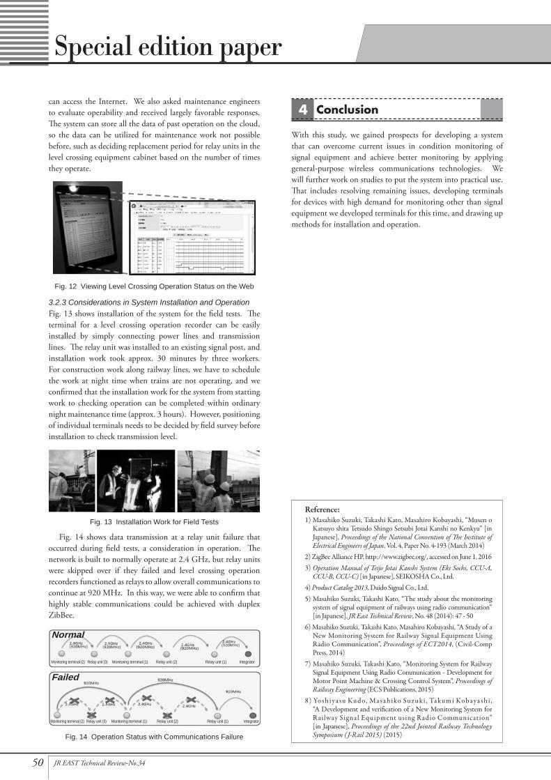
can access the Internet. We also asked maintenance engineers to evaluate operability and received largely favorable responses. The system can store all the data of past operation on the cloud, so the data can be utilized for maintenance work not possible before, such as deciding replacement period for relay units in the level crossing equipment cabinet based on the number of times they operate.
3.2.3 Considerations in System Installation and Operation Fig. 13 shows installation of the system for the field tests. The terminal for a level crossing operation recorder can be easily installed by simply connecting power lines and transmission lines. The relay unit was installed to an existing signal post, and installation work took approx. 30 minutes by three workers. For construction work along railway lines, we have to schedule the work at night time when trains are not operating, and we confirmed that the installation work for the system from starting work to checking operation can be completed within ordinary night maintenance time (approx. 3 hours). However, positioning of individual terminals needs to be decided by field survey before installation to check transmission level.
Fig. 14 shows data transmission at a relay unit failure that occurred during field tests, a consideration in operation. The network is built to normally operate at 2.4 GHz, but relay units were skipped over if they failed and level crossing operation recorders functioned as relays to allow overall communications to continue at 920 MHz. In this way, we were able to confirm that highly stable communications could be achieved with duplex ZibBee.
Conclusion4
With this study, we gained prospects for developing a system that can overcome current issues in condition monitoring of signal equipment and achieve better monitoring by applying general-purpose wireless communications technologies. We will further work on studies to put the system into practical use. That includes resolving remaining issues, developing terminals for devices with high demand for monitoring other than signal equipment we developed terminals for this time, and drawing up methods for installation and operation.
Reference:1) Masahiko Suzuki, Takashi Kato, Masahiro Kobayashi, “Musen o
Katsuyo shita Tetsudo Shingo Setsubi Jotai Kanshi no Kenkyu” [in Japanese], Proceedings of the National Convention of The Institute of Electrical Engineers of Japan, Vol. 4, Paper No. 4-193 (March 2014)
2) ZigBee Alliance HP, http://www.zigbee.org/, accessed on June 1, 20163) Operation Manual of Teijo Jotai Kanshi System (Eki Sochi, CCU-A,
CCU-B, CCU-C) [in Japanese], SEIKOSHA Co., Ltd.4) Product Catalog 2013, Daido Signal Co., Ltd.5) Masahiko Suzuki, Takashi Kato, “The study about the monitoring
system of signal equipment of railways using radio communication” [in Japanese], JR East Technical Review, No. 48 (2014): 47 - 50
6) Masahiko Suzuki, Takashi Kato, Masahiro Kobayashi, “A Study of a New Monitoring System for Railway Signal Equipment Using Radio Communication”, Proceedings of ECT2014, (Civil-Comp Press, 2014)
7) Masahiko Suzuki, Takashi Kato, “Monitoring System for Railway Signal Equipment Using Radio Communication - Development for Motor Point Machine & Crossing Control System”, Proceedings of Railway Engineering (ECS Publications, 2015)
8) Yosh iya su Kudo, Ma sa h iko Suzu ki , Ta kum i Ko b aya sh i , “A Development and verification of a New Monitoring System for Railway Signal Equipment using Radio Communication” [in Japanese], Proceedings of the 22nd Jointed Railway Technology Symposium (J-Rail 2015) (2015)
Monitoring terminal (2) Relay unit (3) Monitoring terminal (1) IntegratorRelay unit (2) Relay unit (1)
Monitoring terminal (2) Relay unit (3) Monitoring terminal (1) IntegratorRelay unit (2) Relay unit (1)
Normal
Failed
Fig. 14 Operation Status with Communications Failure
Fig. 12 Viewing Level Crossing Operation Status on the Web
Fig. 13 Installation Work for Field Tests